Zhejiang Flashforge 3D Technology GUIDERIIS 3D Printer User Manual
Zhejiang Flashforge 3D Technology CO., Ltd. 3D Printer
UserManual.wiki
>
Zhejiang Flashforge 3D Technology
>
GUIDERIIS User Manual
User Manual
Navigation menu
Upload a User Manual
Namespaces
Wiki Guide
HTML
PDF
Info
Views
User Manual
Discussion / Help
Navigation
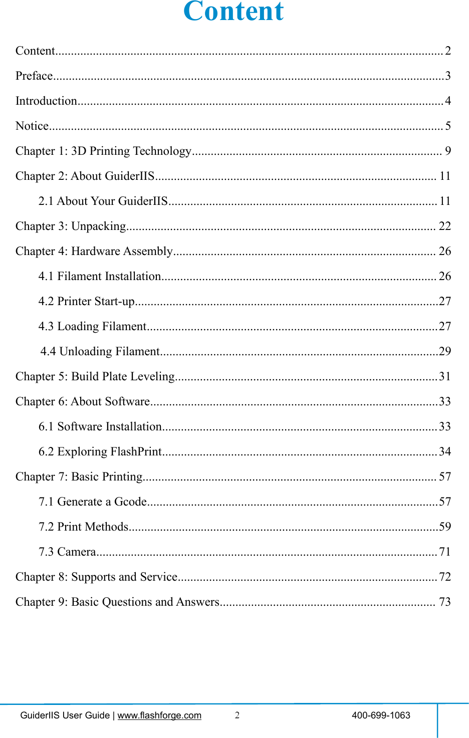

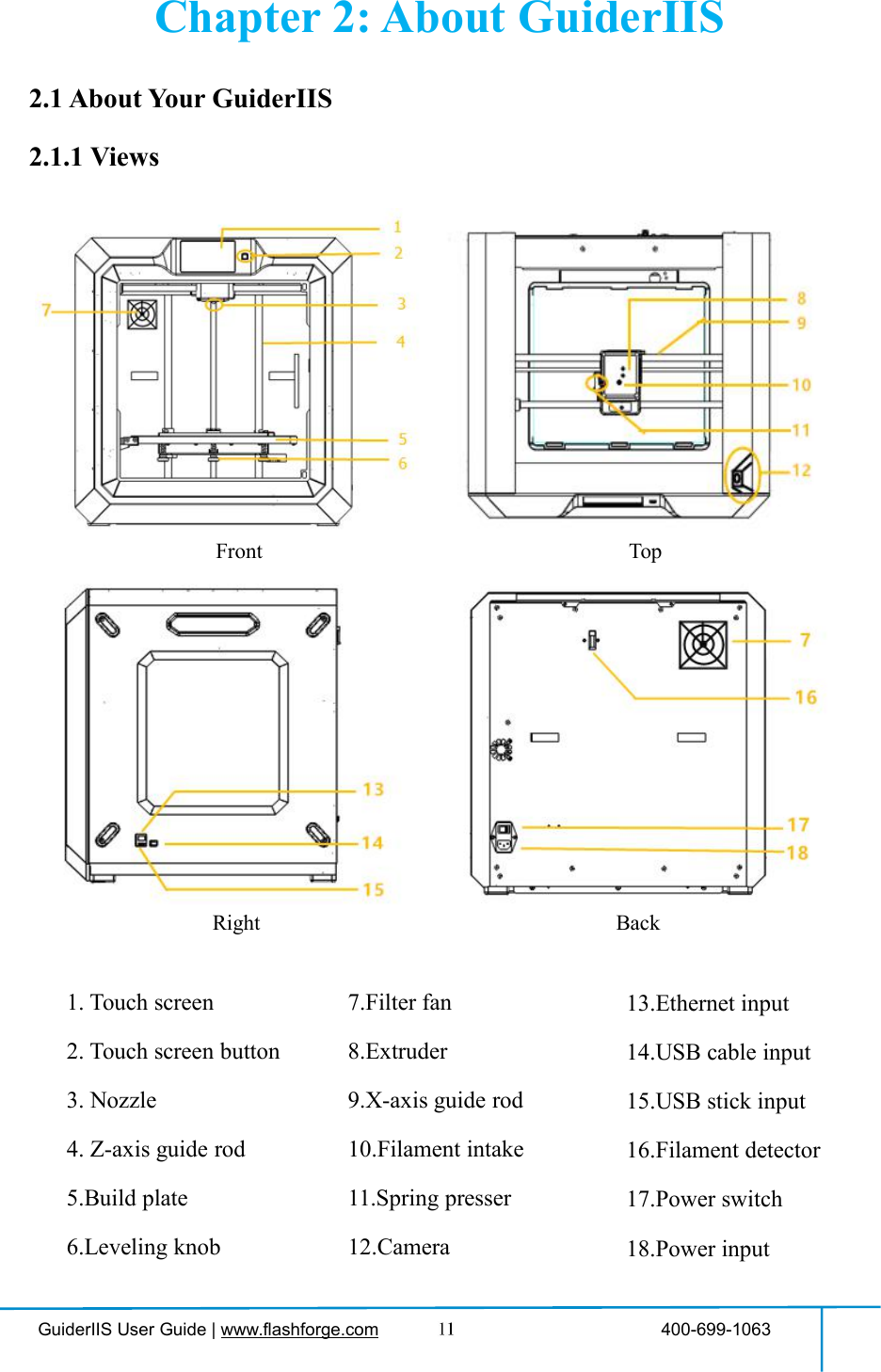
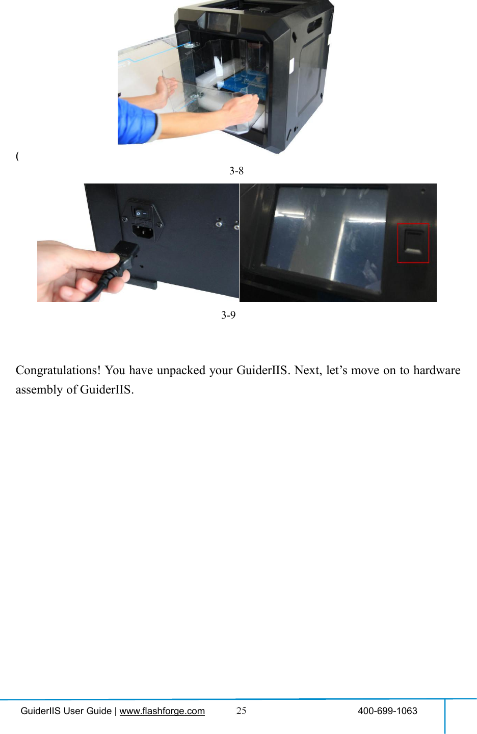
![GuiderIIS User Guide | www.flashforge.com 400-699-1063To set extruder temperature during printing:After extruder temperature has reachedtarget temperature, temperature figure willbe underlined in print interface,Tap [Yes] to save the setting while tap [No]to cancel the setting.Tools in print interfacePrinting speed: To change printing speedduring printing by tapping the underlinedspeed figure.Light bulb: To turn on/off the light.Filament: To change filament duringprinting. (Note: You need to suspend theprinting operation first)Cancel: To end the tool orders and returnto the print interface.To set the printing speed during printingTap [Yes] to save the setting while tap [No]to cancel the setting.Preheat](https://usermanual.wiki/Zhejiang-Flashforge-3D-Technology/GUIDERIIS/User-Guide-3850542-Page-15.png)
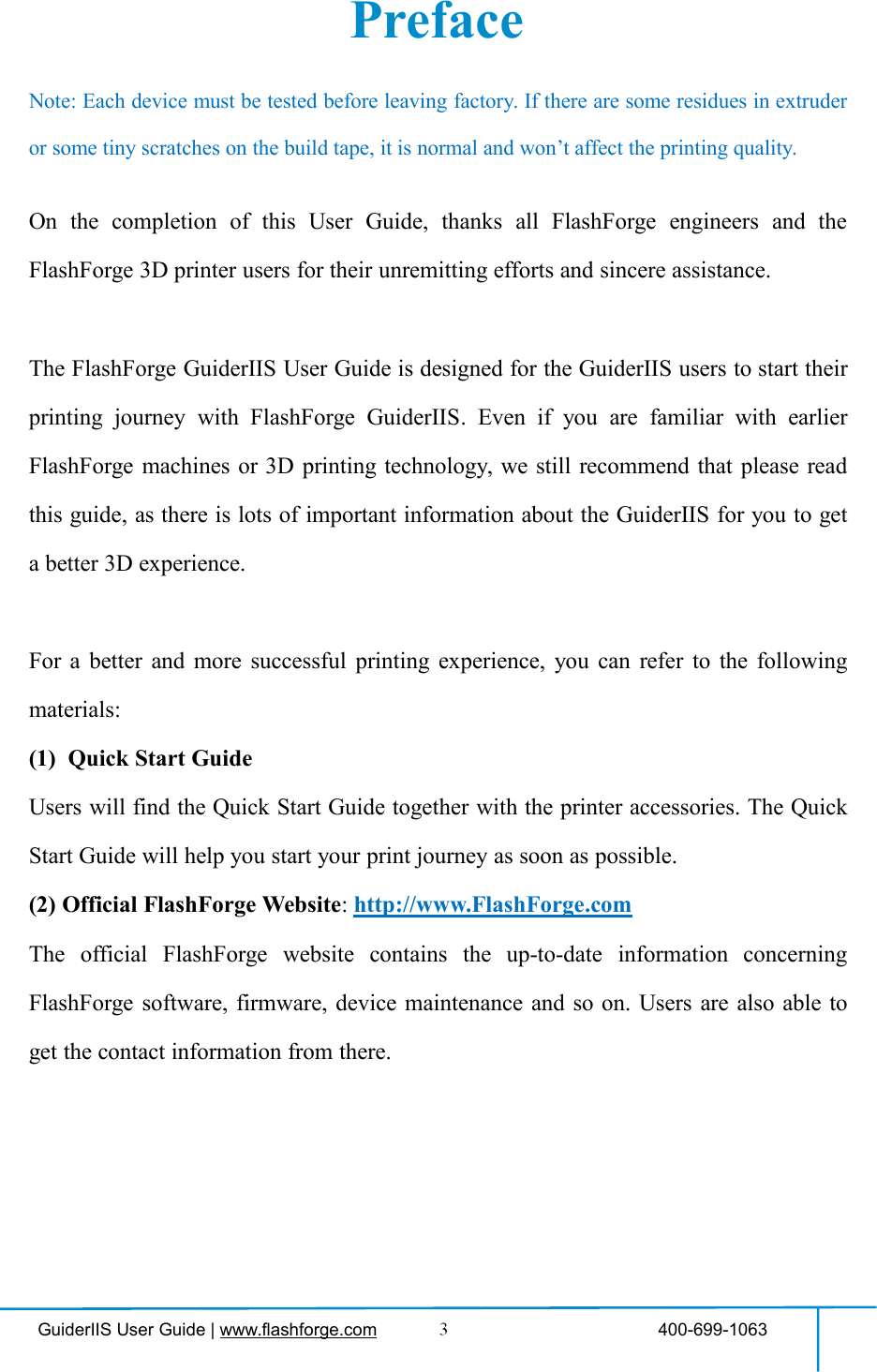
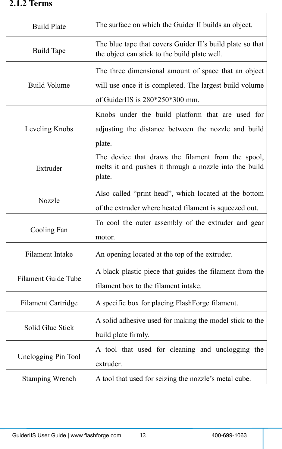
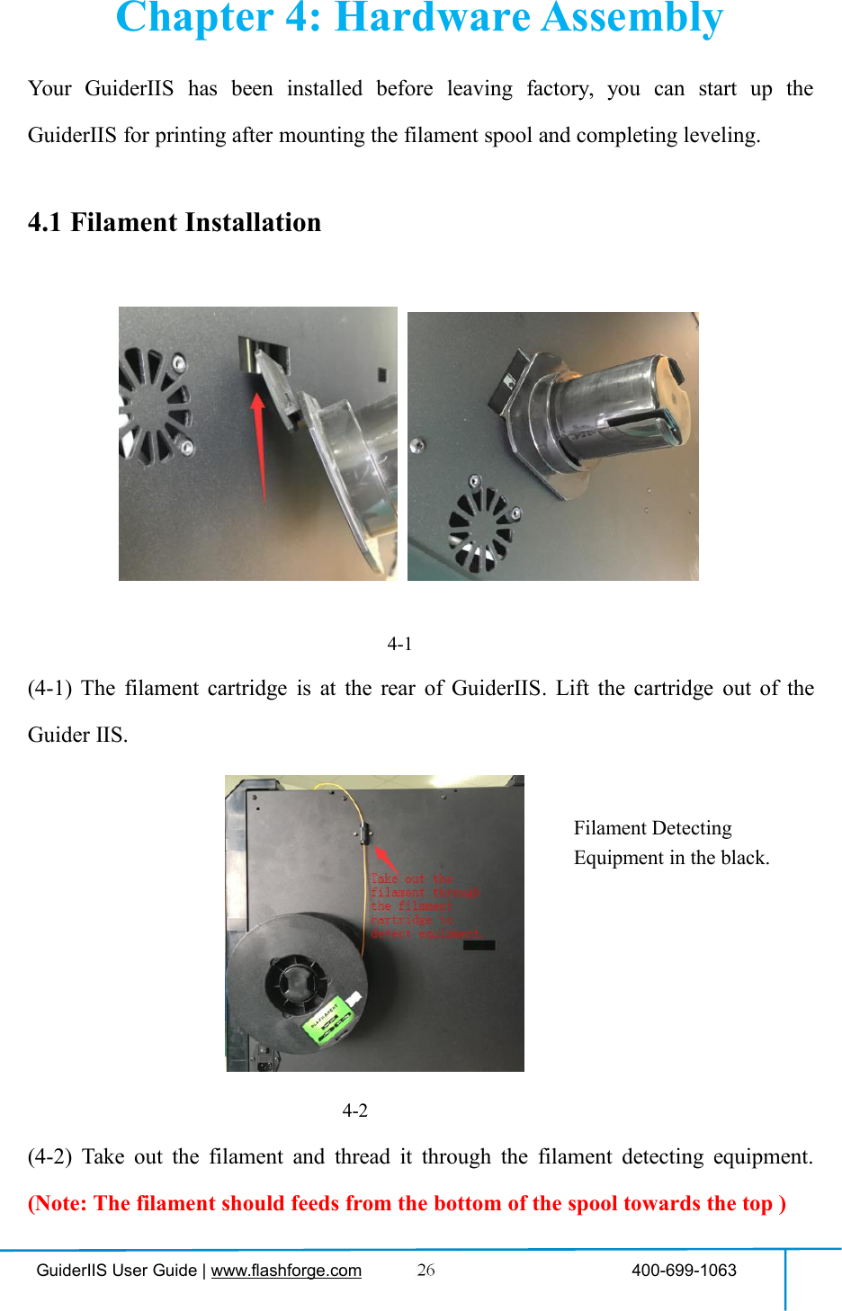
![GuiderIIS User Guide | www.flashforge.com 400-699-1063Tap the [Preheat] button to enter thepreheat interface. Tap the [Start] button toheat up to the setting temperature.The default temperature is 220℃.Tap the temperature display bar to set thetemperature.To set the preheat temperature.Tap [Yes] to save the setting while tap [No]to cancel the setting.The picture displays the preheat interface. Itshows the actual temperature and the targettemperature. Tap the [Abort] button to abortthe preheat job.ToolsTap [Tools] to enter tool options.Filament: To load/unload the filament.Level: To adjust the build plate.Home: To make the X, Y and Z axes backto the zero point.Manual: To manually adjust the positionsof X, Y and Z axes.Setting: To implement relevant functionsetups.Status: The check the real-time status ofthe printer.About: Information about the printer.Back](https://usermanual.wiki/Zhejiang-Flashforge-3D-Technology/GUIDERIIS/User-Guide-3850542-Page-16.png)
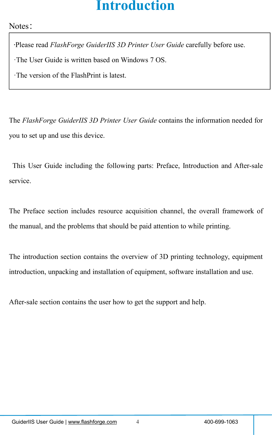
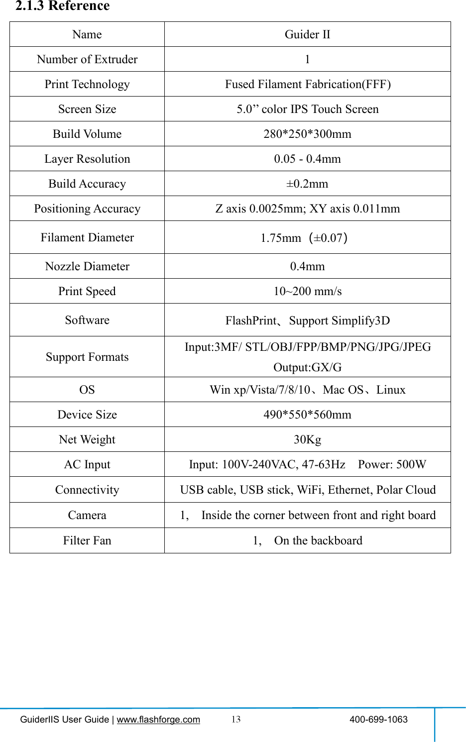
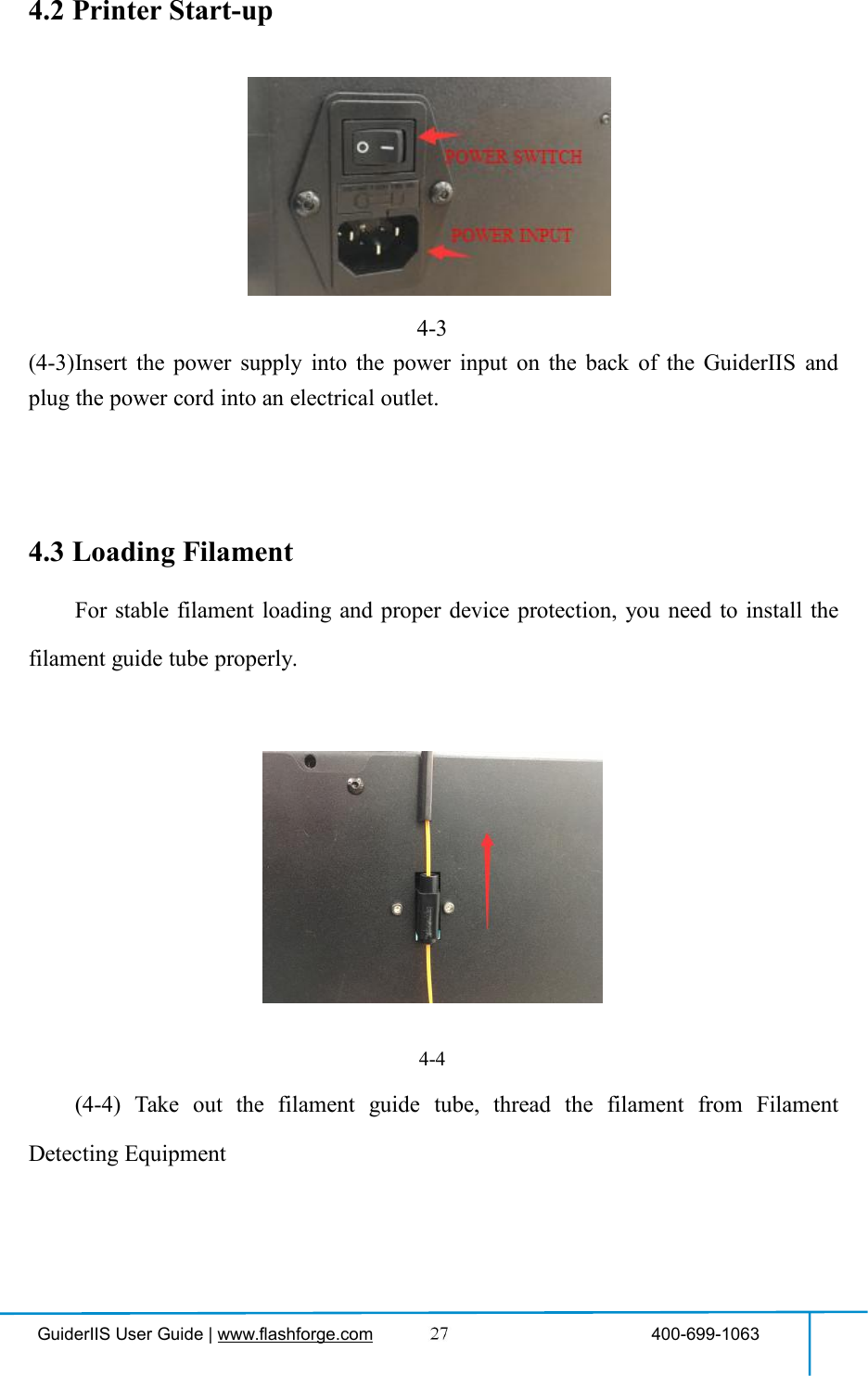
![GuiderIIS User Guide | www.flashforge.com 400-699-1063Manual adjustmentY+: The extruder moves to the zero point,that is, the back of the machineY-: The extruder moves to the directionopposite to the Y+.X+: The extruder moves to the zeropoints, that is, to the right directionX-: The extruder moves to the directionopposite to the X+.Z+: The build plate elevates.Z-: The build plate descends.BackTap [Setting] to enter the setting interfaceLanguage: To set the display languageResume Print: Resume print afterrestarting Guider IISWiFi: To turn on/off the WiFiWLan hotspot: To turn on/off the WLanhotspot.Polar Cloud Connection: To turn on/offthe Polar Cloud Connection.Extruder Calibration: To adjust the initialdistance between the extruder and the buildplate.Startup Sound: To turn on/off the StartupSound.Filament Check: To turn on/off thefilament checkLight Bar Control: To turn on/off thelight bar control.Light Bar Brightness: To adjust the lightbar brightness.Factory Reset: Return to factory settingUpdate: To update the firmware version.Back](https://usermanual.wiki/Zhejiang-Flashforge-3D-Technology/GUIDERIIS/User-Guide-3850542-Page-17.png)
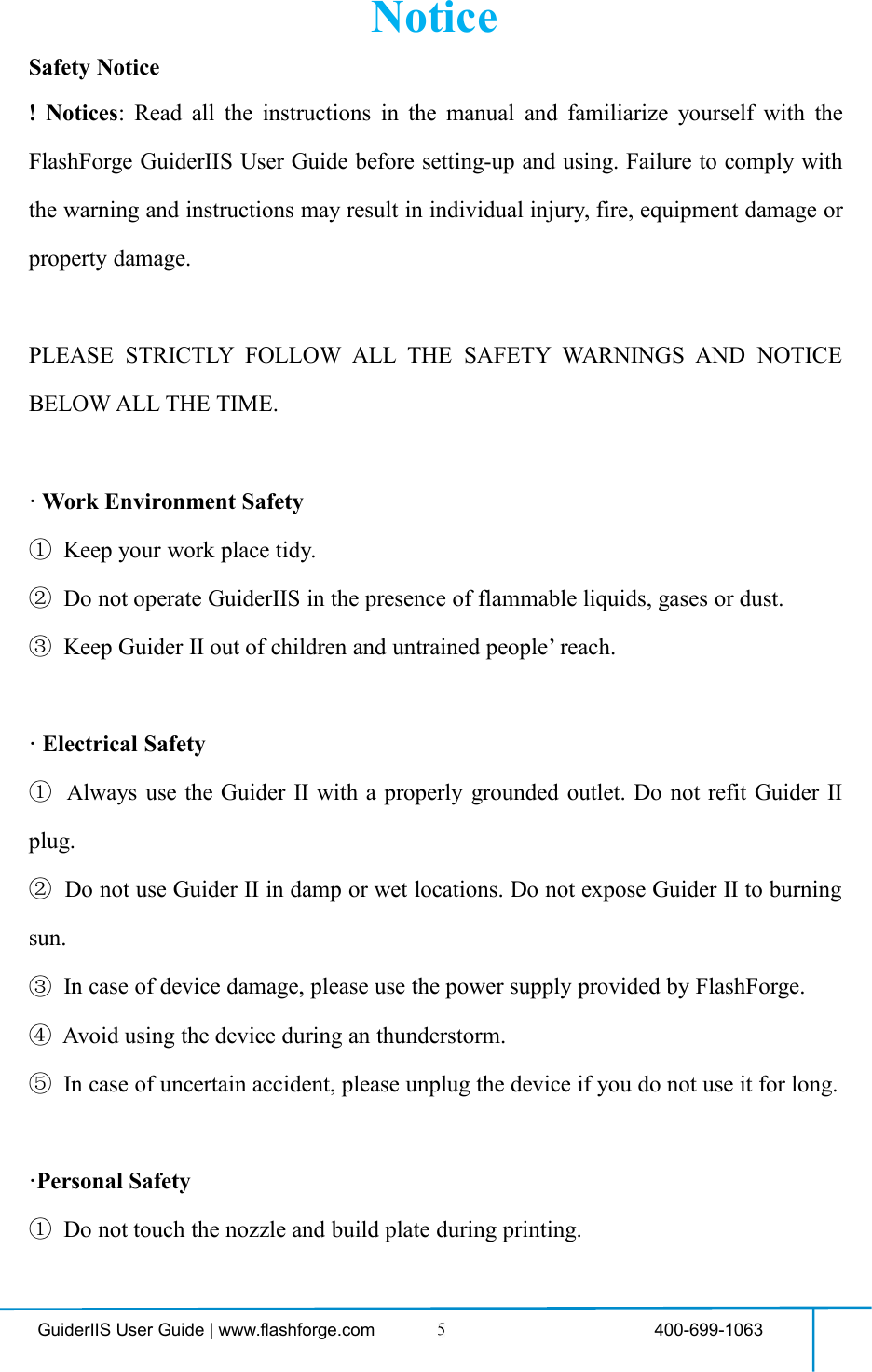
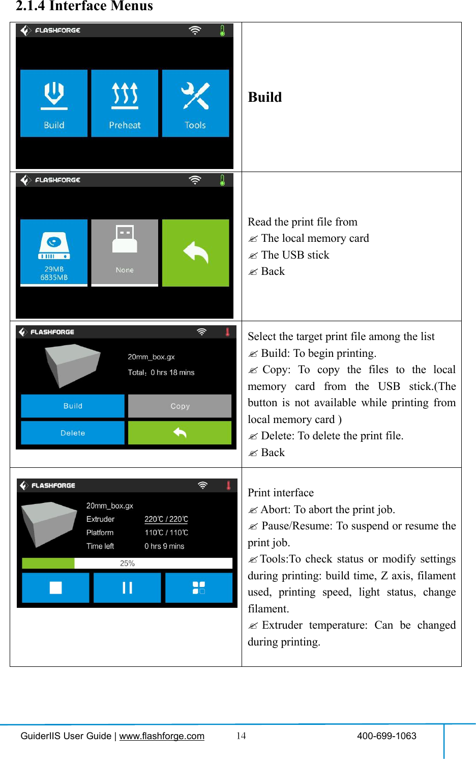
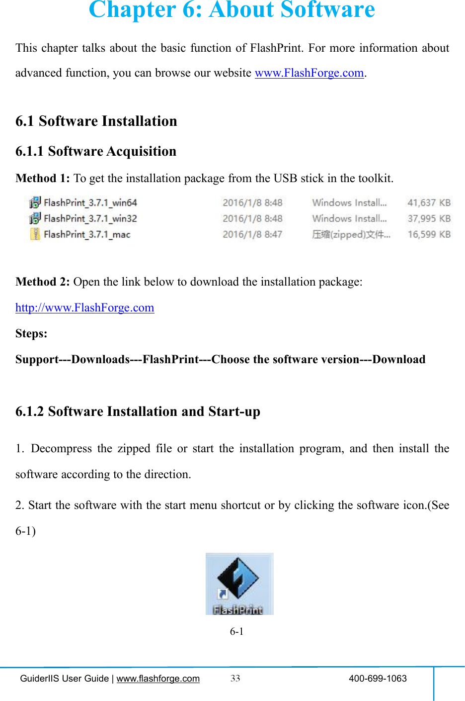
![GuiderIIS User Guide | www.flashforge.com 400-699-1063Turn on [Resume Print]Left picture showed is the [Resume Print]turned on status. If the printer is turned offwhen current print job has not finished yet,printer will continue and resume previousprinting job after restarted.(Note: If [Resume Print] is turned off, thisfunction will not apply. )WiFi:Turn on WiFi: Turn on the WiFi, releasethe WiFi hotspot and set the WiFi oncomputerBackWLan hotspotOFF/On: To turn on/off the Wlan hotspot.Setup Wlan hotspot: To set the SSID andpassword.SSID: The name of hotspot.Password: The password of hotspot.Save: To save the setting.Back](https://usermanual.wiki/Zhejiang-Flashforge-3D-Technology/GUIDERIIS/User-Guide-3850542-Page-18.png)
![GuiderIIS User Guide | www.flashforge.com 400-699-1063Polar Cloud Connection:Cloud Connection: To turn on/off the polarcloud connection.Setup Cloud Connection: To set cloudconnection ID and PIN which have alreadybeen registered on: https://polar3d.comID: The email address of your Cloudaccount.PIN: The PIN code of your Cloud account.Save: To save the setting.Back(Note: To use polar cloud printing function,you need to connect the printer to internetwith WiFi or Ethernet Cable first)Extruder Calibration:(not recommended for customers to operate)To adjust the initial distance between theextruder and the build plate by tapping[-]and[+]. The proper distance may be oneordinary paper’s thickness.Turn on [Filament Check]:Left picture showed is the [FilamentCheck] turned on status.Filament abnormal status will be detectedwhen filament is used up or suspended.[Filament Check] function should be usedwith filament in the filament cartridge.Thisfunction is invalid if using filament out ofthe cartridge.](https://usermanual.wiki/Zhejiang-Flashforge-3D-Technology/GUIDERIIS/User-Guide-3850542-Page-19.png)
![GuiderIIS User Guide | www.flashforge.com 400-699-1063Turn off [Filament Check]:Left picture showed is the [FilamentCheck] turned off status.Filament abnormal status won’t be detectedwhen filament is used up or suspended.Turn on/off [Startup Sound]:Tap to turn on/off the sound when restartthe printer.Light Bar Control: To turn on/off thelight bar control.Light Bar Brightness: To click and selectdifferent light bar brightness.Factory Reset: Return to factory settingUpdate: To update the firmware version.BackLight Bar Brightness: To click and selectdifferent light bar brightness.Status:It displays the real-time status of theextruder temperature and other details.About:It displays the basic information about thedevice.](https://usermanual.wiki/Zhejiang-Flashforge-3D-Technology/GUIDERIIS/User-Guide-3850542-Page-20.png)
![GuiderIIS User Guide | www.flashforge.com 400-699-10634-5(4-5) Insert the filament from the filament guide tube into the filament intake.Next, we will load the FlashForge filament.(Note: Please lower the build plate toincrease the distance between the nozzle and build plate to 50mm at least foravoiding nozzle jam.)(4-7) Tap [Tool].图4-64-84-7](https://usermanual.wiki/Zhejiang-Flashforge-3D-Technology/GUIDERIIS/User-Guide-3850542-Page-28.png)
![GuiderIIS User Guide | www.flashforge.com 400-699-1063(4-8) Tap [Filament]--[Load]4-9(4-9)After the extruder’s temperature reaches 220℃, the printer will sound a beep toprompt you to load the filament into the extruder.4-10(4-10)Insert the filament into the extruder at an upright angle. Then the filament willbe drawn through the extruder. Do not tap [Cancel] until the filament load the extrudersteadily.4.4 Unloading Filament4-11](https://usermanual.wiki/Zhejiang-Flashforge-3D-Technology/GUIDERIIS/User-Guide-3850542-Page-29.png)
![GuiderIIS User Guide | www.flashforge.com 400-699-1063(4-11) Tap [Tool]-[Unload] and the extruder starts heating up.4-12(4-12) After the extruder reaches 220℃, the printer will sound a beep to prompt you tounload the filament from the extruder. Press the spring presser, press down thefilament for about three seconds and gently pull the filament out.Note: Do not pull out the filament with force as it will damage the gears. If themelted filament has cooled down in the extruder, please repeat the steps above.](https://usermanual.wiki/Zhejiang-Flashforge-3D-Technology/GUIDERIIS/User-Guide-3850542-Page-30.png)
![GuiderIIS User Guide | www.flashforge.com 400-699-1063Chapter 5: Build Plate LevelingGuiderIIS creatively adopts three-point intelligent leveling system, which will giveclear and comprehensive feedback to users. There are three spring-loaded knobs underthe build platform. The distance between the plate and nozzle increases whiletightening the knobs. On the contrary, the distance reduces.(5-1) Tap [Tools] - [Level] on your GuiderIIS touch screen. Please wait while theextruder and platform finish initial movements. After that, operate according to theguide on the touch screen.5-2(5-2) After tapping [Yes], the extruder starts to move towards the first point and theplate moves up and down to verify the distance between nozzle and plate.5-1](https://usermanual.wiki/Zhejiang-Flashforge-3D-Technology/GUIDERIIS/User-Guide-3850542-Page-31.png)
![GuiderIIS User Guide | www.flashforge.com 400-699-10635-3(5-3) When it shows that the distance is too big, please unscrew all three nuts underplatform clockwise for the same rounds until hearing a steady beep and the [Verify]button appears.5-4(5-4) If the distance is appropriate, tap [OK] to second point leveling. If still not,please follow the prompts to adjust the first point screw again till you see [OK] button.5-5(5-5) Repeat steps according to the prompts on the touch screen to complete secondand third points leveling and then finally Tap [Finish] to exit.Leveling operating has completed!](https://usermanual.wiki/Zhejiang-Flashforge-3D-Technology/GUIDERIIS/User-Guide-3850542-Page-32.png)
![GuiderIIS User Guide | www.flashforge.com 400-699-10636.2 Exploring FlashPrint6. 2.1 Machine Type Selection! After starting FlashPrint, you need to select the target machine type first.When you start FlashPrint, a dialog box will pop up. Just select FlashForge Guider ⅡSin the machine type list and click [OK]. You can also change the machine type viaclicking [Print]--[Machine type]. See graphic 6-2:6-26.2.2 Software Introduction](https://usermanual.wiki/Zhejiang-Flashforge-3D-Technology/GUIDERIIS/User-Guide-3850542-Page-34.png)
![GuiderIIS User Guide | www.flashforge.com 400-699-1063Load files.Enter the support edit modePrint it directly with your GuiderIIS or export to your USB StickView FlashPrint home screen from one of six viewing anglesMove model around on XY-plane; shift+click to move along Z axisTurn and rotate your modelScale the size of your objectCut model into several parts6.2.3 LoadingYou can load a model file or Gcode file into your FlashPrint by the following sixmethods:Method 1: Click the [Load] icon on the main interface. Then select theobject file.Method 2: Select the file for loading and drag the file to the main interface of thesoftware.Method 3: Click [File]--[Load File]. Then select the object file for loading.Method 4: Click [File]--[Examples]to load the example filesMethod 5: Click [File]--[Recent Files]to load the files opened recently.Method 6: Select and drag the target file to the icon of FlashPrint.](https://usermanual.wiki/Zhejiang-Flashforge-3D-Technology/GUIDERIIS/User-Guide-3850542-Page-35.png)
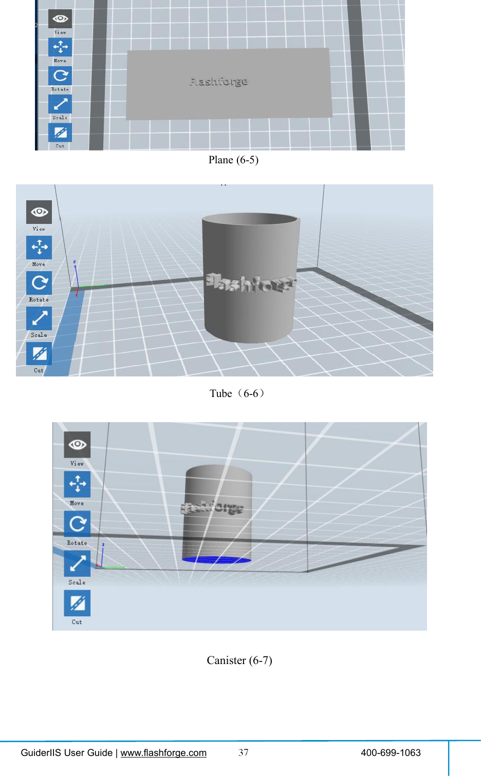
![GuiderIIS User Guide | www.flashforge.com 400-699-1063Lamp (6-8)Seal (6-9)6.2.4 Views①Changing viewsChange model views by moving, rotating, scaling.●DragClick the [View] icon and then you can move the object by the following threemethods:Method 1: Hold down the left mouse button and drag.](https://usermanual.wiki/Zhejiang-Flashforge-3D-Technology/GUIDERIIS/User-Guide-3850542-Page-38.png)
![GuiderIIS User Guide | www.flashforge.com 400-699-1063Method 2: Hold down the mouse wheel and scroll up and down.Method 3: Hold down the Shift key, hold down the right mouse button and drag.●RotateClick the [View] icon and then you can rotate the object by the following twomethods:Method 1. Hold down the right mouse button and drag.Method 2. Hold down the Shift key, hold down the left mouse button and drag.●ScaleRotate the mouse wheel to enlarge or shrink the build plate.②Set ViewAllow users to view the object on the build plate. Six views are under the view menu,that is, bottom view, top view, front view, back view, left view and right view.Method 1: Click the the [View] button, there are six views in the drop- down listMethod 2: Click the the [Look] icon on the left, click it again and a submenuwill appear with six views for selecting.③Reset ViewAllow users to reset views by the following two methods:Method 1: Click the [View] menu and select [Home View]Method 2: Click the [View]button on the left, click it again and you will see theviewing options, you can click [Reset].④Show Model OutlineClick [View]--[Show Model Outline], it will highlight the yellow border of the object](https://usermanual.wiki/Zhejiang-Flashforge-3D-Technology/GUIDERIIS/User-Guide-3850542-Page-39.png)
![GuiderIIS User Guide | www.flashforge.com 400-699-1063⑤Show Steep OverhangClick [View]--[Show Steep Overhang]. When the intersection angle between themodel surface and horizontal line is within the overhang threshold value, the surfacehas steep overhang and it becomes red in the software. Overhang threshold valuecould be set as needed. The default value is 45 degree.6.2.5 MoveSelect the object and move the object by the following two methods:Method 1: Click the [Move] icon on the left, hold down the left mouse button anddrag to adjust the location of the model in XY direction. Hold down the Shift key,hold down the left mouse button and drag to adjust the location of the model in Zdirection. The distance and the direction of the movement shall be displayed.Method 2: Click the [Move]button on the left and then enter the distance value. Click[Reset]to reset distance values.Note: Users shall click [Center] and [On Platform] after the location adjustment toensure the model(s) be within the build area and on the build platform. If a specifiedposition is needed, only click [On Platform].6.2.6 RotateSelect the target object and rotate the object by the following two methods:Method 1: Click the [Rotate] icon on the left and three mutually perpendicular ringsappear around the object Click one ring and rotate on the present axis, you will see therotation angle and direction in the center of circle. In this way, you could make themodel rotate on X/Y/Z axis.Method 2: Click the [Rotate] icon on the left, and then enter into rotating angelvalues in X/Y/Z axes positioning. Click [Reset] to reset rotating angel values.](https://usermanual.wiki/Zhejiang-Flashforge-3D-Technology/GUIDERIIS/User-Guide-3850542-Page-40.png)
![GuiderIIS User Guide | www.flashforge.com 400-699-10636.2.7 ScaleSelect the target object and scale the object by the following two methods:Method 1: Click the [Scale] icon on the left, hold down the left mouse button andscale the model. The corresponding values will display near the object.Method 2: Click the [Scale] icon on the left and then enter into scale values in X/Y/Zaxes positioning. Click the [Maximum] button to get largest size possible for building.Click [Reset] to reset the size of model.Note: If the [Uniform Scaling] radio button is clicked, it will scale the model in equalproportion when changing value in any positioning of the model. Otherwise it willonly change the value of the corresponding positioning.6.2.8 CutLeft-click on the model to select it and double-click on the [Cut] icon to set the cutplane. The direction and position are available for setting.①Draw with Mouse②X Plane](https://usermanual.wiki/Zhejiang-Flashforge-3D-Technology/GUIDERIIS/User-Guide-3850542-Page-41.png)
![GuiderIIS User Guide | www.flashforge.com 400-699-1063③Y Plane④Z Plane6.2.9 SupportsAfter loading the model, click [Edit]--[Supports]or click the Supports icon directly,then you will enter the support edit mode (as shown in the picture below). Click [Back]to exit when you finish editing.6-10](https://usermanual.wiki/Zhejiang-Flashforge-3D-Technology/GUIDERIIS/User-Guide-3850542-Page-42.png)
![GuiderIIS User Guide | www.flashforge.com 400-699-1063①Support OptionsClick the Support Options, an option box will appear, supports options include“treelike” and “linear”, when choose “treelike”, click [OK], then it will generatetreelike structure; when choose “linear”, click [OK], then it will generate linearstructure; if it is a model with supports, when you choose one of the supports options,software will judge whether existing supports need to be deleted or not on the basis ofthe type of existing support, and will pop up the corresponding prompt to let you makethe choice.②Auto SupportsClick the [Auto Supports] button, the software will judge the position where supportsare needed and generate corresponding treelike or linear supports. If it is a model withsupports, the existing supports will be deleted and new supports will be generated.③Add SupportsSupports will be added once clicking the [Add]button. Move the cursor to theposition where supports needed, left-click to choose the starting point of supports, holddown the left mouse button and drag the mouse the supports preview will show up (ifsupport surface doesn’t need support or the support column angle is too large, will6-11](https://usermanual.wiki/Zhejiang-Flashforge-3D-Technology/GUIDERIIS/User-Guide-3850542-Page-43.png)
![GuiderIIS User Guide | www.flashforge.com 400-699-1063highlight the support review). Loosen the left mouse button, if support column doesn’tmeet with model, then support will be generated on origin and terminal point (thehighlighted preview support won’t generate support structure )④Clear SupportsClick [Clear Supports], all supports will be deleted. The operation can be repealedvia clicking [Undo]or pressing the shortcut key Ctrl+Z.⑤Delete SupportsSupports will be deleted once clicking the [Delete]button. Move the cursor to thesupports needed deleting, current supports and its subnode support will be highlighted,click the left mouse button to delete these highlighted support.6.2.10 Print①Preview: Choose to enter preview interface or not②Print when slice done: Print or not when slice done③Material type: Choose according to the type of model④Supports: When print suspended structure models, support is necessary. Click[supports] to create support part for the printing.](https://usermanual.wiki/Zhejiang-Flashforge-3D-Technology/GUIDERIIS/User-Guide-3850542-Page-44.png)
![GuiderIIS User Guide | www.flashforge.com 400-699-1063⑤Raft: This function will help the model to stick well on the platform.⑥Wall: During dual color printing, this function will help to clear the leakingfilament of another extruder.⑦Brim: Expand the outline of model’s bottom layers to a Brim which helps anchorthe edges of the model to the plate to avoid warping.⑧Resolution:You have three resolution solutions (with default setting)to choose from,high resolution is corresponding with slow printing speed, opposite for the lowresolution. For PLA printing, an extra solution “Hyper” is available.⑨More options: Click [More options] to set for layer, shell, infill, speed andtemperature. Different resolution solution is corresponding to different defaults, click[Restore Defaults] to back to default setting.●Layera. Layer: Layer thickness of the printing model. With a small value, the surfaceof the model will be smoother.b. First Layer Height: This is the first layer of the model, which will affect thesticking performance between the model and platform. Maximum is 0.4mm, usuallythe default is OK.c. Shell: Contains the outside shell value, capping layer value (under vase pattern,top solid layer setting is invalid.)● Perimeter Shells: Maximum is 10a. Top Solid Layer: Maximum is 30, minimum is 1.b. Bottom Solid Layer: Maximum is 30, minimum is 1.● Infilla. Fill Density means fill rate.b. Fill Pattern is the pattern of filling shape which effects printing duration.](https://usermanual.wiki/Zhejiang-Flashforge-3D-Technology/GUIDERIIS/User-Guide-3850542-Page-45.png)
![GuiderIIS User Guide | www.flashforge.com 400-699-1063c. Combine Infill: You can select the layers for combining according to the layerthickness. The combined thickness should not exceed 0.4mm. “Every N layers” is for all theinfills while “Every N inner layers” is only for inner infills, which generally can save printtime.6-13● Speeda. Print Speed is the moving speed of the extruder. Generally, the lower speed is,the better print you will get. For PLA printing, 80 is recommended.b. Travel Speed is to control the moving speed of the extruder undernon-printing Status during work. For PLA printing, 100 is recommended.Note: Modify parameters settings to get better prints as different models need differentparameters.● TemperatureExtruder Temperature: Recommended extruder temperature is 220℃.Note: Different temperatures have subtle influences in prints. Please adjust thetemperature according to the condition in order to get a good print.Platform Temperature: To set the temperature of Platform.● OthersCooling Fan Control: Set up the time to turn on the cooling fan. You canpre-set the height and make the cooling fan begin to work at the point.Pause At Heights: Allows users to pre-set a height in which the print willsuspend automatically. The function usually applied when you want to change thefilament at a certain point. (6-14) Click [Edit], then you can add or remove a height.](https://usermanual.wiki/Zhejiang-Flashforge-3D-Technology/GUIDERIIS/User-Guide-3850542-Page-46.png)
![GuiderIIS User Guide | www.flashforge.com 400-699-10636.2.11 File Menus①New ProjectClick [File]--[New Project]can build a blank project. If there is an unsavedmodification on previous project, then it will inform you whether the modificationneeds to be saved or not. Click [Yes]will save the modification, while click [No]willabandon it. If click [Cancel]or close tool tip, then will cancel the new project.②SavingAfter finishing the model edit and adjustment, there are two ways below to save allmodels in the scene.Method 1:Click [File]--[Save Project] in the menu bar to save the file as a project file with the“.fpp” suffix, all models in the scene (include support) are independent. Afterreloading the files, extruder configuration information and model position will be thesame as the configuration during saving.Method 2:6-156-14](https://usermanual.wiki/Zhejiang-Flashforge-3D-Technology/GUIDERIIS/User-Guide-3850542-Page-47.png)
![GuiderIIS User Guide | www.flashforge.com 400-699-1063Click on [File]--[Save as...] to save the model as project file .fpp or .stl and .obj.For .stl and .boj, models are integrated as one(include support part). If load it again,only the position of the model was saved, not included the printing parameters.③PreferencesClick [File]--[Preferences], you can choose language and if needs detecting updatewhen start●Language: The software supports several languages, namely, Chinese (simplifiedChinese and traditional Chinese), English, French, Korean, Japanese and so on.●Font Size: Set the font size.●Auto layout newly-imported model: Set Yes or No.●Printing Window Type: Including Base Mode and Expert Mode●Check for Update after start up: It is used to preset if it is necessary to activate theonline automatic update function, if choose yes, every time when you open software, itcan online detect if it is a new version software, once new version found, it willreminds users to download and install new version firmware.6.2.12 Edit Menus①UndoAllows users to undo the recent edits by the following two methods:Method 1: Click [Edit]--[Undo].Method 2: Press the shortcut Ctrl+Z.②Redo6-16](https://usermanual.wiki/Zhejiang-Flashforge-3D-Technology/GUIDERIIS/User-Guide-3850542-Page-48.png)
![GuiderIIS User Guide | www.flashforge.com 400-699-1063Allows users to redo the most recent edit you have undone to your model file by thefollowing two methodsMethod 1: Click [Edit]--[Redo]Method 2: Press the shortcut Ctrl+Y.③Empty Undo-stackTo clean up the recorded operating steps so as to release the memory.④Select AllBy the following two methods, you could select all models in the scene. (Whenmodels are too small to be seen or out of viewing scope, please click [Center] and[Scale] buttons to adjust the model.)Method 1: Click [Edit]--[Select All].Method 2: Press the shortcut Ctrl+A.⑤DuplicateSelect the object and duplicate the object through the following two methods:Method 1: Click [Edit]--[Duplicate]Method 2: Press the shortcut Ctrl+D⑥DeleteSelect the object and delete the object through the following two methods:Method 1: Click [Edit]--[Delete]Method 2: Press the shortcut Delete⑦Auto Layout AllClick [Edit]--[Auto Layout All]after loading one or more than one models, allmodels will be placed automatically as automatic placement rule.⑧Repair Models](https://usermanual.wiki/Zhejiang-Flashforge-3D-Technology/GUIDERIIS/User-Guide-3850542-Page-49.png)
![GuiderIIS User Guide | www.flashforge.com 400-699-1063Click [Edit]--[Repair Models] to repair models.⑨SupportsClick [Edit]--[Supports] to enter supports setting interface.6.2.13 Print Menus①Connect MachineYou can connect the Guider ⅡS with your PC via USB cable or WiFi or Ethernet Cable.Note: The machine icon on the bottom right displays the connection status:ConnectedDisconnectedMethod 1:Connect Via USB Cablea. Connect your GuiderIIS with your PC via an USB cable.b. Turn on your GuiderIIS and start FlashPrint.c. Click [Print]--[Connect Machine],then select USB in the [Connection Mode]option and select machine you want to connect in [Select Machine] option. If you cannot find your machine, click the [Rescan] button to scan your machine and select it.Finally click [Connect] button to connect to the printer. If you still can not find yourmachine after rescan, it means you haven’t installed the driver in the software.](https://usermanual.wiki/Zhejiang-Flashforge-3D-Technology/GUIDERIIS/User-Guide-3850542-Page-50.png)
![GuiderIIS User Guide | www.flashforge.com 400-699-1063Method 2:Connect Via WiFi①Connect Guider ⅡS with your PC under AP modea.Turn on your Guider ⅡSb. Tap [Tools]-[Setting]-[WLan hotspot]-[WLan hotspot ON].c. Click on the wireless network setting in your computer, and find the wirelesssignal-“Guider ⅡS”. Click [Connect] to connect your computer with Guider ⅡS viaWlan hotspot.d. Click [Print]-[Connect Machine] on FlashPrint. Then the following dialogbox pops up. You need to select “Wi-Fi” in Connect Mode. Enter into the IP Addressshown on the interface and then click [Connect].If successfully connected, you will see the following mark on the right corner.②Connect Guider ⅡS with your PC under STA modea. Tap [Tools]-[Setting]-[WiFi]-[WiFi ON] to turn on the WiFi of Guider IIS and](https://usermanual.wiki/Zhejiang-Flashforge-3D-Technology/GUIDERIIS/User-Guide-3850542-Page-51.png)
![GuiderIIS User Guide | www.flashforge.com 400-699-1063connect your computer and Guider IIS with the same WiFi signal.b. Click [Print]-[Connect Machine] on FlashPrint. Then the following dialogbox pops up. You need to select “Wi-Fi” in Connect Mode. Enter into the IP Addressshown on the interface and then click [Connect].If successfully connected, you will see the following mark on the right corner.Disconnect GuiderIISClick [Print]--[Disconnect] to disconnect your PC and GuiderIIS.Method 3:Connect Via Etherneta. Connect your GuiderIIS with your PC via an Ethernet cable.b. Turn on your GuiderIIS and start FlashPrint.b. Click [Print]-[Connect Machine] on FlashPrint. Then the following dialogbox pops up. You need to select “Ethernet” in Connect Mode. Enter into the IPAddress shown on the interface and then click [Connect].](https://usermanual.wiki/Zhejiang-Flashforge-3D-Technology/GUIDERIIS/User-Guide-3850542-Page-52.png)
![GuiderIIS User Guide | www.flashforge.com 400-699-10636.2.14 Tool Menus①Control PanelAfter connecting PC with GuiderIIS, click [Tools]--[Control Panel] to open thecontrol panel.●Jog Controlsa. Jog Mode:Select the distance that extruder/ build plate move a single time (that is,](https://usermanual.wiki/Zhejiang-Flashforge-3D-Technology/GUIDERIIS/User-Guide-3850542-Page-53.png)
![GuiderIIS User Guide | www.flashforge.com 400-699-1063the distance extruder/ build plate move upon your single click).b. Six blue arrow direction buttons: Control the move along X/Y/Z axis. X/Y axisbutton control extruder move, Z axis button control build plate move. Click X-,extruder will move leftward a specified distance; Click X+, extruder will move aspecified distance rightward. Click Y-, extruder will move forward a specified distance;Click Y-, extruder will move backward a specified distance. Click Z-, build plate willmove upward a specified distance; Click Z-, build plate will move downward aspecified distance. (Specified distance refers to the move distance you set in JogMode.c. Stop: Click the [Stop] button to abort the current movement.d. XYZ coordinate frame on the right side: Show the current position ofextruder/build plate.e. Make Current Position Zero button: Set the current position of theextruder/build plate as (0, 0, 0). (NOTE: X, Y, and Z boxes are for display purposes.Changing the value in the boxes will not affect anything.f. Center X/Y/Z button: Extruder and build platform will back to the zero (0, 0, 0)you set last time.g. X/Y Speed and Z Speed: Set the move speed of extruder/ build platform.●Limit Switch: In order to protect your GuiderIIS, three limit switches are equippedto control the maximum position, and the three limit switches corresponding to X/Y/Zaxis limit switch. It has two statuses:a. Not Triggered: If the extruder/build plate don’t move to its maximum, X/Y/Z axislimit switch is not triggered, and shows “Not Triggered”.b. Triggered: If the extruder/build plate moves to its maximum, X/Y/Z axis limitswitch is triggered, and shows “Triggered”.●Stepper Motor Controls: Allows users to control to stepper motor. Click [Enable],and lock the motor so it does not allow any movement; click [Disable], and unlock the](https://usermanual.wiki/Zhejiang-Flashforge-3D-Technology/GUIDERIIS/User-Guide-3850542-Page-54.png)
![GuiderIIS User Guide | www.flashforge.com 400-699-1063motor to be controlled manually.●LED Color: Allow users to change the LED color of GuiderIIS.●Extruder Controls: You can set the value of “Motor Speed (RPM)”, which cancontrol the rotation speed of filament feeding wheel. The motor rotation time can becontrolled via setting the value of “Extruder Duration”. Generally we suggest theusers choose option of continuous time 60 seconds. The filament must be loaded in theextruder before motor starts. Therefore, do not start rotation operation until theextruder temperature reaches to the printing temperature of filament. For PLAfilament, the extruder temperature should reach 200℃, after reaching the extrudertemperature, click the [Forward]/[Reverse] rotation button to control filament loadand filament unload. Furthermore, if you want to stop filament load and unload, youcan click [Stop].●Temperature Control: Input the temperature you want to get in the left frame, click[Apply], the printer will automatically heat the corresponding part, the right sideshows the current actual temperature of corresponding part. After starting heating, thebelow curve of temperature form will start to change, different color corresponddifferent parts’ temperatures②Update FirmwareNOTE!Please update firmware under instructions of Flashforge engineer, Do notrecommend updating on your own.Every time when you start FlashPrint, it will automatically detect and download theup-to-date firmware. If any update is available, a dialog box will pop up for remindingthe users to update.Step 1: Click [Tools]--[Update firmware]. It needs to cut off connection beforeupdating firmware. If software and printer are already in connection, it reminds youcutting off the connection, and then choose [Yes] and go on to the next step.](https://usermanual.wiki/Zhejiang-Flashforge-3D-Technology/GUIDERIIS/User-Guide-3850542-Page-55.png)
![GuiderIIS User Guide | www.flashforge.com 400-699-1063Step 2: Choose corresponding printer type and firmware version and click [OK] in thefirmware updating box. After confirming the printer is in free state, the software willautomatically update the firmwareStep 3:Reboot you Guider Ⅱ and wait for 4-5 seconds, then you can see the updateprocess bar. When the update finishes, it will go back to the main interface.Step 4:Tap [Tools]--[About] to check whether the updated version is right.③On Board PreferencesWhen the computer and printer are in connection, click [Tools]--[On BoardPreferences], you can check the printer name.④Machine informationWhen the computer and printer are in connection state, click [Tools]--[Machineinformation], you can check the machine type, machine name and firmware etc.6.2.15 Help Menus①First Run Wizard②Help Contents:Click [Help]--[Help Contents], you can read the help contents.③Check for Updates :Click [Help]--[Check for Update] to detect the availableupdates online.④About FlashPrint :Click [Help]--[About FlashPrint], the software informationbox will pop up. The contents include the current software version and copyrightinformation.](https://usermanual.wiki/Zhejiang-Flashforge-3D-Technology/GUIDERIIS/User-Guide-3850542-Page-56.png)
![GuiderIIS User Guide | www.flashforge.com 400-699-1063Chapter 7: Basic PrintingThis chapter will provide a step-by-step guide on turning a 3D model into a physicalreality. Before proceeding, it is recommended that you’d better go over prior chapterson loading/unloading filament, leveling the build platform, and the functions andcapabilities of FlashPrint.7.1 Generate a Gcode(7-1)Double-click the icon of FlashPrint to start the software.7-1(7-2)Click [Print]--[Machine Type] to select FlashForge GuiderIIS7-2(7-3)Click the [Load] icon to load a .stl model file and the object will display on thebuild area.7-3(7-4)Click [Edit]--[Surface to Platform] to make your model perfectly positioned34](https://usermanual.wiki/Zhejiang-Flashforge-3D-Technology/GUIDERIIS/User-Guide-3850542-Page-57.png)
![GuiderIIS User Guide | www.flashforge.com 400-699-1063on the build area. Click [Back] and double-click the Move icon again, then click [Onthe Platform] and [Center] to ensure the model be on the platform.7-4Note:If you’ve place your model in a right place, you can skip the step above.(7-5) Click the [Print] icon on the top, you should make some setups for your printjob.Preview: If you check the [Preview] box, you can preview your model after slicing is](https://usermanual.wiki/Zhejiang-Flashforge-3D-Technology/GUIDERIIS/User-Guide-3850542-Page-58.png)
![GuiderIIS User Guide | www.flashforge.com 400-699-1063done.Print When Slice Done: If you print via USB cable, you can check the box, while ifyou print via USB, you should not check the box.Machine Type: FlashForge Guider ⅡSSupports: If you print a model with supports, you should click the inverted triangleand select [Enable].Raft: You are suggested to select [Enable].Resolution: You are suggested to select [Standard]More Options: You are suggested to keep them default.Click [OK] to select the path to save the Gcode file. You can rename the file as youlike and save it as a .g or .gx file, click [Save] to generate a Gcode file.Note: .gx files are available for preview while the .g files are not. They are displayingas follows:g. Files gx. Files7-7Next, we are going to print the model.7.2 Print MethodsAfter generating the Gcode file, you can transfer it to your Guider ⅡS. You cantransfer the file through USB cable ,USB stick,WiFi , and Ethernet cable.7.2.1 Print from Computer (USB cable connection)①Connect your GuiderIIS with your PC via a USB cable.(Please refer to 6.2.13 )②Turn on your Guider ⅡS, level the build plate and load the filament.](https://usermanual.wiki/Zhejiang-Flashforge-3D-Technology/GUIDERIIS/User-Guide-3850542-Page-59.png)
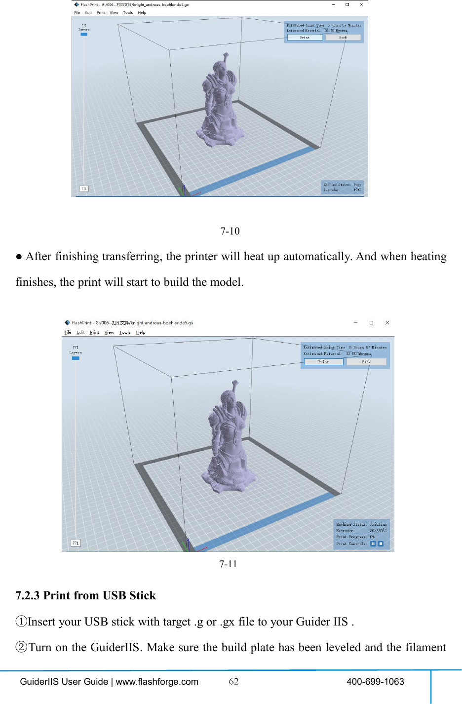
![GuiderIIS User Guide | www.flashforge.com 400-699-1063③Click [Print]and transfer your Gcode file to your Guider ⅡS. After completingtransference, the printer will heat up automatically. And when heating finishes, theprint will start to build the model.④When your PC connects with FlashPrint successfully. The status box on thebottom right displays the real-time nozzle temperature. After finishing preheating,your Guider Ⅱ starts the print job directly.7.2.2 Print from Computer (WiFi connection)①Connect your GuiderⅡS with your PC via WiFi. (2 WiFi connection methods,Please refer to 6.2.13 )Enter into the IP Address shown on your GuiderIIS interface and then click[Connect].](https://usermanual.wiki/Zhejiang-Flashforge-3D-Technology/GUIDERIIS/User-Guide-3850542-Page-60.png)
![GuiderIIS User Guide | www.flashforge.com 400-699-1063②Turn on your Guider ⅡS, level the build plate and load the filament.③Click [Print]and transfer your Gcode file to your Guider ⅡS. Aftercompleting transference, the printer will heat up automatically. And when heatingfinishes, the printer will start to build the model.If you want to print a Gcode from a local folder, you just need to load the file intoFlashPrint at the status of USB connection or WiFi connection or Ethernet connection,then click the [Print] button on the top-right.●Load the target Gcode file into FlashPrint.7-9●Click the [Print] button, the PC will transfer the Gcode file to the printer.](https://usermanual.wiki/Zhejiang-Flashforge-3D-Technology/GUIDERIIS/User-Guide-3850542-Page-61.png)
![GuiderIIS User Guide | www.flashforge.com 400-699-1063is loaded.③Tap [Print] and then tap the USB Stick icon in the middle. The file(s) will bedisplayed on the screen. Select the file you want to print and tap [Print]. The file willbe transferred to the printer.⑥And the printer will heat up the nozzle automatically and start to print after thenozzle reaches the aimed temperature.,Abort:To stop heating and printing. Once you tap [Abort], the process is irreversible.Pause:To suspend the print job, you can tap it again to resume it. You can use thisfunction when you want to change the filament halfway.7.2.4 Print from Computer (Ethernet Cable connection)①Connect your GuiderIIS with your PC via an Ethernet cable.(Please refer to 6.2.13 )Enter the IP Address shown on your GuiderIIS interface and then click [Connect].](https://usermanual.wiki/Zhejiang-Flashforge-3D-Technology/GUIDERIIS/User-Guide-3850542-Page-63.png)
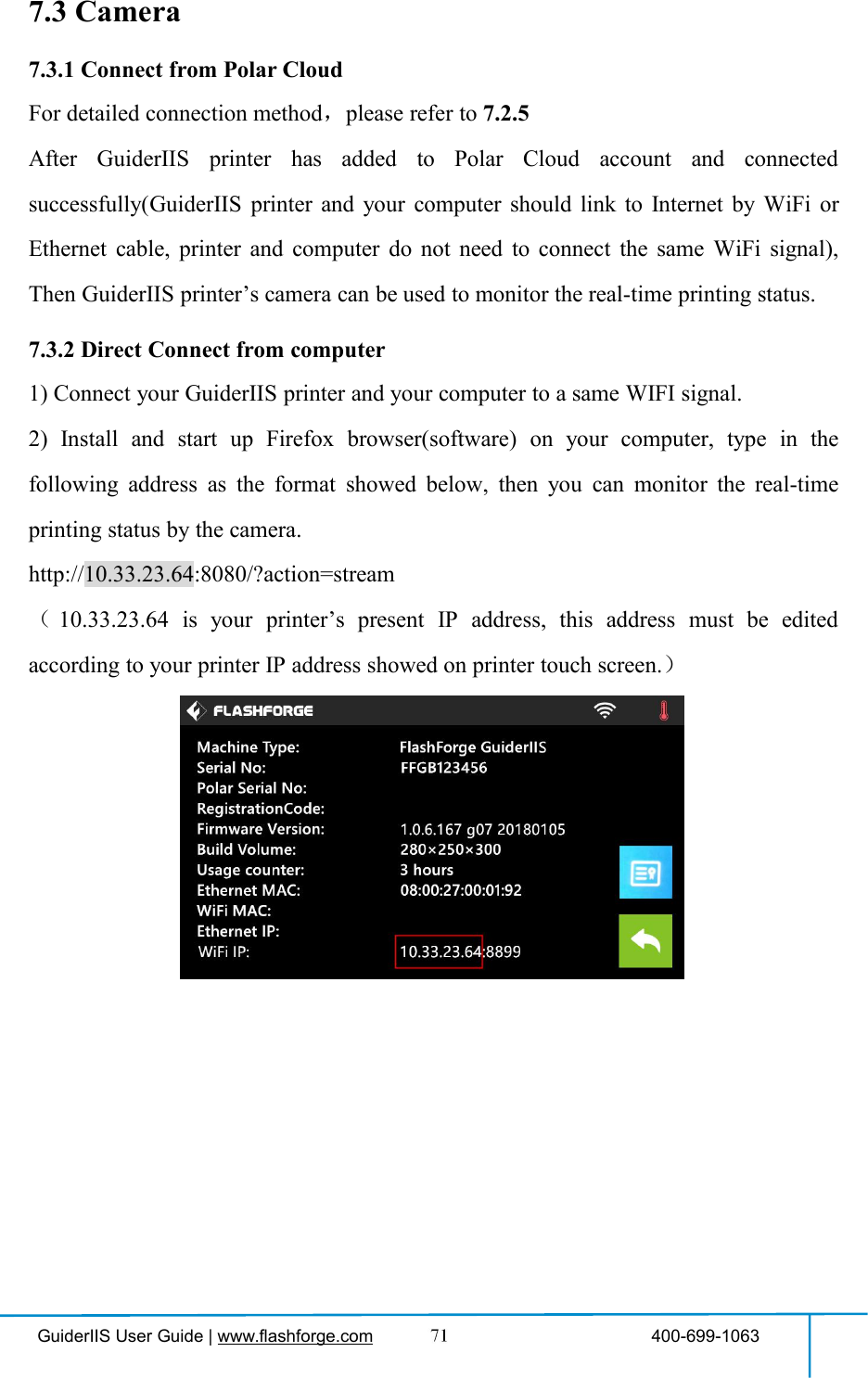
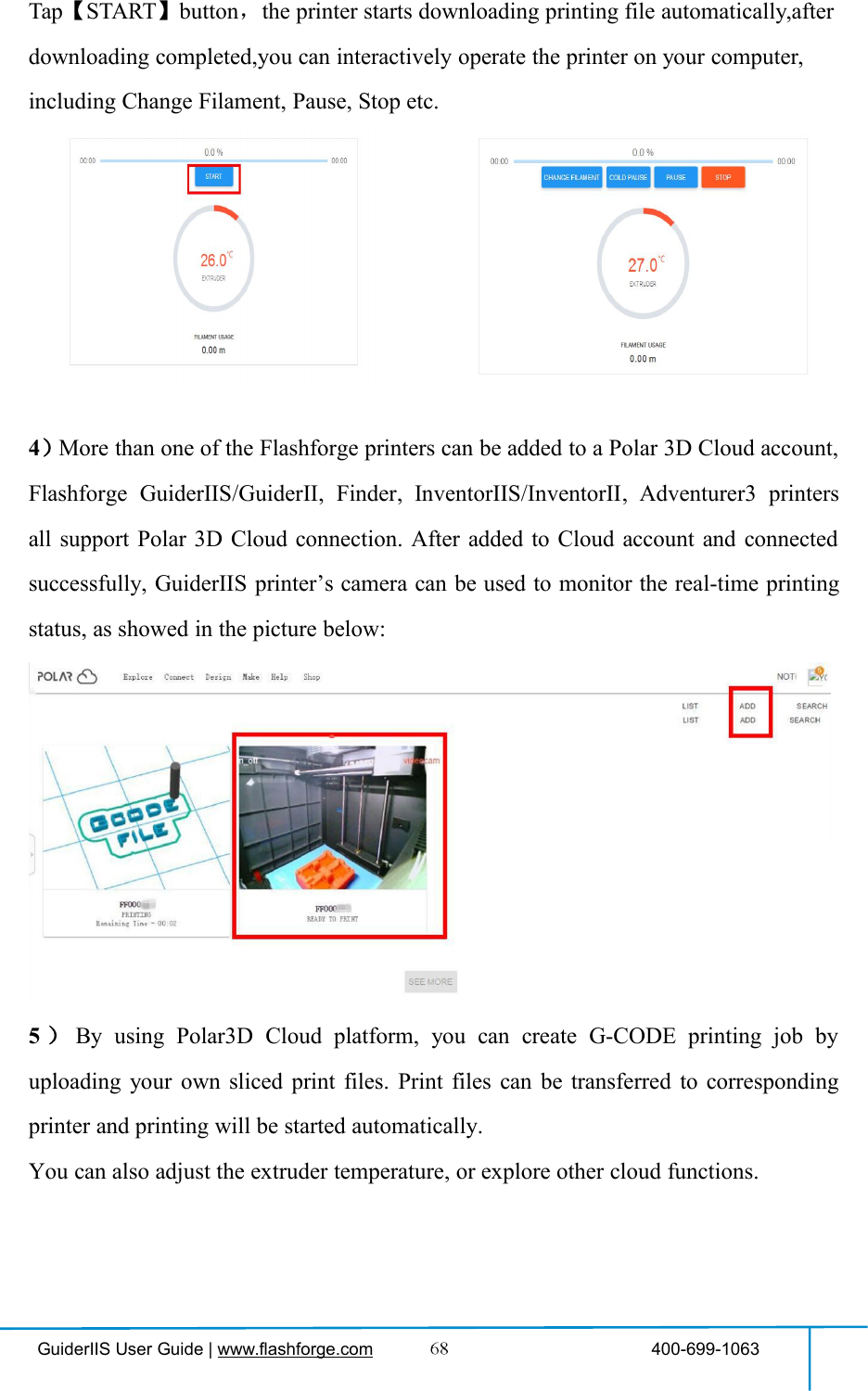
![GuiderIIS User Guide | www.flashforge.com 400-699-1063②Turn on your Guider ⅡS, level the build plate and load the filament.③Click [Print]and transfer your Gcode file to your Guider ⅡS. After completingtransference, the printer will heat up automatically. And when heating finishes, theprint will start to build the model.7.2.5 Print from Polar Cloud connection1)Register a Polar Cloud account with your computer, on website:https://polar3d.com/Register your account using one of the four following options, take the third microsoftlive option as an example, create your new Polar Cloud account.](https://usermanual.wiki/Zhejiang-Flashforge-3D-Technology/GUIDERIIS/User-Guide-3850542-Page-64.png)
![GuiderIIS User Guide | www.flashforge.com 400-699-10632)Enter the Polar Cloud homepage after you create your Polar Cloud account. Tapthe red icon(on the right upper corner showed in the picture below), then Tap [settings],drag down the page to bottom, copy down your Email address and your PIN Code.](https://usermanual.wiki/Zhejiang-Flashforge-3D-Technology/GUIDERIIS/User-Guide-3850542-Page-65.png)
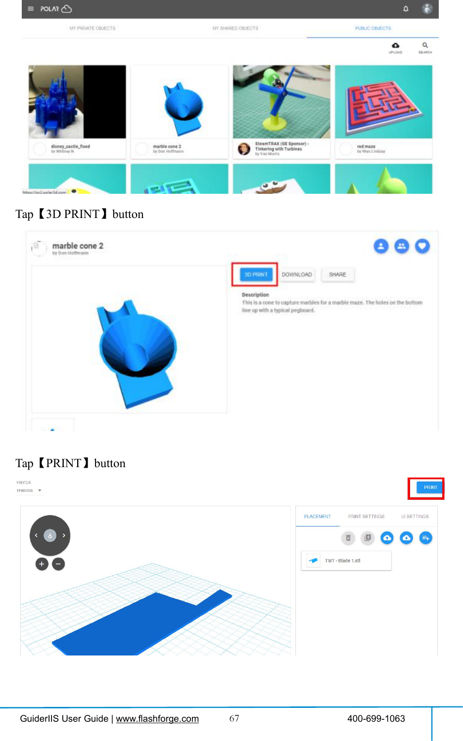
![GuiderIIS User Guide | www.flashforge.com 400-699-1063Connect the printer to internet with WiFi or Ethernet Cable;Tap [Tools]-[Settings]-[Polar Cloud connection] on printer’s touch screen;Input your polar 3D cloud account’s Email address(as ID) and PIN Code, Tap[save] .3)Enter the Polar Cloud homepage with your computer again. Tap [Explore] on theleft upper corner showed in the picture below, then Tap [Objects]Enter the objects page, choose a model you are going to print.](https://usermanual.wiki/Zhejiang-Flashforge-3D-Technology/GUIDERIIS/User-Guide-3850542-Page-66.png)
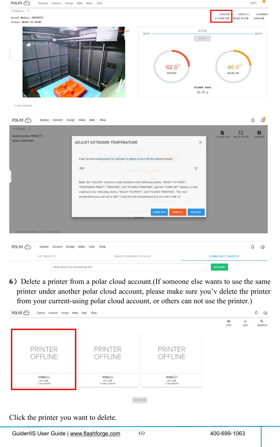
![GuiderIIS User Guide | www.flashforge.com 400-699-1063Click [MANAGE] button on the right upper position of this printer’s details webpage.Then click [SETTINGS] button on the right upper position of the next webpage.Finally, drag the next page to bottom down, click [DELETE PRINTER] button.After you’v completed the above delete steps, this printer can now be used by othersunder his own polar cloud account.](https://usermanual.wiki/Zhejiang-Flashforge-3D-Technology/GUIDERIIS/User-Guide-3850542-Page-70.png)