Zhejiang Flashforge 3D Technology GUIDERIIS 3D Printer User Manual
Zhejiang Flashforge 3D Technology CO., Ltd. 3D Printer
User Manual
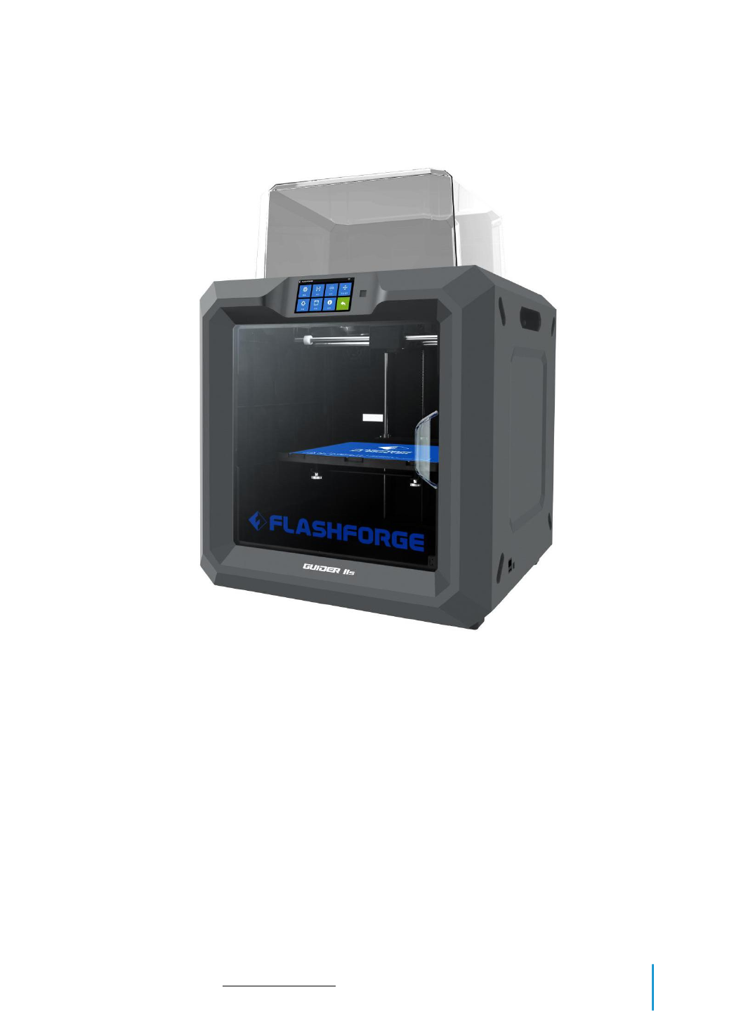

GuiderIIS User Guide | www.flashforge.com 400-699-1063
Content
Content............................................................................................................................ 2
Preface.............................................................................................................................3
Introduction.....................................................................................................................4
Notice.............................................................................................................................. 5
Chapter 1: 3D Printing Technology................................................................................ 9
Chapter 2: About GuiderIIS.......................................................................................... 11
2.1 About Your GuiderIIS...................................................................................... 11
Chapter 3: Unpacking................................................................................................... 22
Chapter 4: Hardware Assembly.................................................................................... 26
4.1 Filament Installation........................................................................................ 26
4.2 Printer Start-up.................................................................................................27
4.3 Loading Filament.............................................................................................27
4.4 Unloading Filament.........................................................................................29
Chapter 5: Build Plate Leveling....................................................................................31
Chapter 6: About Software............................................................................................33
6.1 Software Installation........................................................................................33
6.2 Exploring FlashPrint........................................................................................34
Chapter 7: Basic Printing.............................................................................................. 57
7.1 Generate a Gcode.............................................................................................57
7.2 Print Methods...................................................................................................59
7.3 Camera.............................................................................................................71
Chapter 8: Supports and Service...................................................................................72
Chapter 9: Basic Questions and Answers..................................................................... 73

GuiderIIS User Guide | www.flashforge.com 400-699-1063
Preface
Note: Each device must be tested before leaving factory. If there are some residues in extruder
or some tiny scratches on the build tape, it is normal and won’t affect the printing quality.
On the completion of this User Guide, thanks all FlashForge engineers and the
FlashForge 3D printer users for their unremitting efforts and sincere assistance.
The FlashForge GuiderIIS User Guide is designed for the GuiderIIS users to start their
printing journey with FlashForge GuiderIIS. Even if you are familiar with earlier
FlashForge machines or 3D printing technology, we still recommend that please read
this guide, as there is lots of important information about the GuiderIIS for you to get
a better 3D experience.
For a better and more successful printing experience, you can refer to the following
materials:
(1) Quick Start Guide
Users will find the Quick Start Guide together with the printer accessories. The Quick
Start Guide will help you start your print journey as soon as possible.
(2) Official FlashForge Website:http://www.FlashForge.com
The official FlashForge website contains the up-to-date information concerning
FlashForge software, firmware, device maintenance and so on. Users are also able to
get the contact information from there.

GuiderIIS User Guide | www.flashforge.com 400-699-1063
Introduction
Notes:
The FlashForge GuiderIIS 3D Printer User Guide contains the information needed for
you to set up and use this device.
This User Guide including the following parts: Preface, Introduction and After-sale
service.
The Preface section includes resource acquisition channel, the overall framework of
the manual, and the problems that should be paid attention to while printing.
The introduction section contains the overview of 3D printing technology, equipment
introduction, unpacking and installation of equipment, software installation and use.
After-sale section contains the user how to get the support and help.
·Please read FlashForge GuiderIIS 3D Printer User Guide carefully before use.
·The User Guide is written based on Windows 7 OS.
·The version of the FlashPrint is latest.

GuiderIIS User Guide | www.flashforge.com 400-699-1063
Notice
Safety Notice
! Notices: Read all the instructions in the manual and familiarize yourself with the
FlashForge GuiderIIS User Guide before setting-up and using. Failure to comply with
the warning and instructions may result in individual injury, fire, equipment damage or
property damage.
PLEASE STRICTLY FOLLOW ALL THE SAFETY WARNINGS AND NOTICE
BELOW ALL THE TIME.
· Work Environment Safety
①Keep your work place tidy.
②Do not operate GuiderIIS in the presence of flammable liquids, gases or dust.
③Keep Guider Ⅱ out of children and untrained people’ reach.
· Electrical Safety
①Always use the Guider Ⅱ with a properly grounded outlet. Do not refit Guider Ⅱ
plug.
②Do not use Guider Ⅱ in damp or wet locations. Do not expose Guider Ⅱ to burning
sun.
③In case of device damage, please use the power supply provided by FlashForge.
④Avoid using the device during an thunderstorm.
⑤In case of uncertain accident, please unplug the device if you do not use it for long.
·Personal Safety
①Do not touch the nozzle and build plate during printing.

GuiderIIS User Guide | www.flashforge.com 400-699-1063
②Do not touch the nozzle after finishing printing.
③Dress properly. Do not wear loose clothing or jewelry. Keep your hair, clothing
and gloves away from moving parts.
④Do not operate the device while you are tired or under the influence of drugs,
alcohol or medication.
· Cautions
①Do not leave the device unattended for long.
②Do not make any modifications to the device.
③To lower the build plate before loading/unloading filament. (The distance between
the nozzle and build plate should be kept for at least 50mm)
④Operate the device in a well-ventilated environment.
⑤Never use the device for illegal activities.
⑥Never use the device to make any food storage vessels.
⑦Never use the device to make any electrical appliance.
⑧Never put the model into your mouth.
⑨Do not remove the models with force.
⑩Never connect the device with network cable longer than 3m.
· Environment Requirements
Temperature: RT 15-30℃
Moisture: 20%-70%
· Place Requirements
The device must be placed in a dry and ventilated environment. The distances of the
left, right and back side space should be at least 20cm, and the distance of the front
side space should be at least 35cm.

GuiderIIS User Guide | www.flashforge.com 400-699-1063
· Filament Requirements
Do not abuse the filament. Please make sure you use the FlashForge filament or the
filament from the brands accepted by FlashForge.
· Filament Storage
All polymers degrade with time. Do not unpack until filament is needed. Filament
should be stored at clean and dry conditions.
Legal Notice
All the information in this document is subject to any amendment or change without
the official authorization from FlashForge.
FLASHFORGE CORPORATION MAKES NO WARRANTY OF ANY KIND WITH
REGARD TO THIS DOCUMENT, INCLUDING, BUT NOT LIMITED TO, THE
IMPLIED WARRATIES OF MERCHANTABILITY AND FITNESS FOR A
PARTICULAR PURPOSE.
FlashForge shall not be liable for errors contained herein for incidental consequential
damages in connection with furnishing, performance or use of this material
FCC STATEMENT:
This device complies with Part 15 of the FCC Rules. Operation is subject to the
following two conditions:
(1) This device may not cause harmful interference,
(2) This device must accept any interference received, including interference that may
cause undesired operation.
Warning: Changes or modifications not expressly approved by the party responsible

GuiderIIS User Guide | www.flashforge.com 400-699-1063
for compliance could void the user's authority to operate the equipment.
This equipment has been tested and found to comply with the limits for a Class B
digital device, pursuant to Part 15 of the FCC Rules. These limits are designed to
provide reasonable protection against harmful interference in a residential installation.
This equipment generates uses and can radiate radio frequency energy and, if not
installed and used in accordance with the instructions, may cause harmful interference
to radio communications. However, there is no guarantee that interference will not
occur in a particular installation. If this equipment does cause harmful interference to
radio or television reception, which can be determined by turning the equipment off
and on, the user is encouraged to try to correct the interference by one or more of the
following measures:
Reorient or relocate the receiving antenna.
Increase the separation between the equipment and receiver.
Connect the equipment into an outlet on a circuit different from that to which the
receiver is connected.
Consult the dealer or an experienced radio/TV technician for help.
This document contains proprietary information protected by copyright.
Copyright © 2018 FlashForge Corp. All Rights Reserved

GuiderIIS User Guide | www.flashforge.com 400-699-1063
Chapter 1: 3D Printing Technology
3D printing refers to transforming three-dimensional models into physical objects that
you can hold and touch. It is also called additive manufacturing because the 3D model
is created by “adding” layers upon layers of material until the object is fully formed.
Fused Filament Fabrication (FFF) is the most common method of 3D printing. It is
also the method that the GuiderIIS uses. It works by melting plastic material called
filament onto a print surface in high temperature. The filament solidifies after it cools
down, which happens instantaneously after it is extruded from the nozzle. 3D objects
are formed with the filament laying down multiple layers.
1.1 Process
3D printing involves three steps:
1.) Make or download a 3D model
2.) Slice and export the 3D model
3.) Build the 3D model
1.1.1 Make a 3D Model:
Currently, there are three ways to creating a 3D model.
·Designing From Scratch You can use free CAD (computer-aided design) software
such as 3DTADA, AutoCAD, SolidWorks, Pro-E, and our own software Happy 3D to
design your own 3D model.
·3D Scanners An alternative method to creating a 3D model is to scan an object. 3D
scanners work by digitizing a physical object, collecting its geometric data, and saving
it to a file on your PC. There are also apps that can turn a mobile device into a 3D
scanner.
GuiderIIS User Guide | www.flashforge.com 400-699-1063
·From the Cloud The most popular way of obtaining a 3D model is to download it
from websites that allow users to upload 3D models that they designed.
E.g. : www. thingiverse.com
1.1.2 Slice and Export the 3D Model:
Slice software is the software that prepares 3D models for printing and turns them into
instructions for the 3D printers. FlashPrint is the slicing software used for the
FlashForge GuiderIIS.
Using FlashPrint, you can turn .stl files into .g or .gx files for printing. Then the files
can be transferred to your GuiderIIS via USB cable, USB stick ,Wi-Fi or Ethernet
cable.
GuiderIIS support Simplify3D software, software not developed by FlashForge may
need register or charge extra fee, please choose to use(or not) according to your needs.
1.1.3 Build the 3D Model:
Once the output file has been transferred to your GuiderIIS, it will start to turn the 3D
model into a physical object by laying down layers of filament.
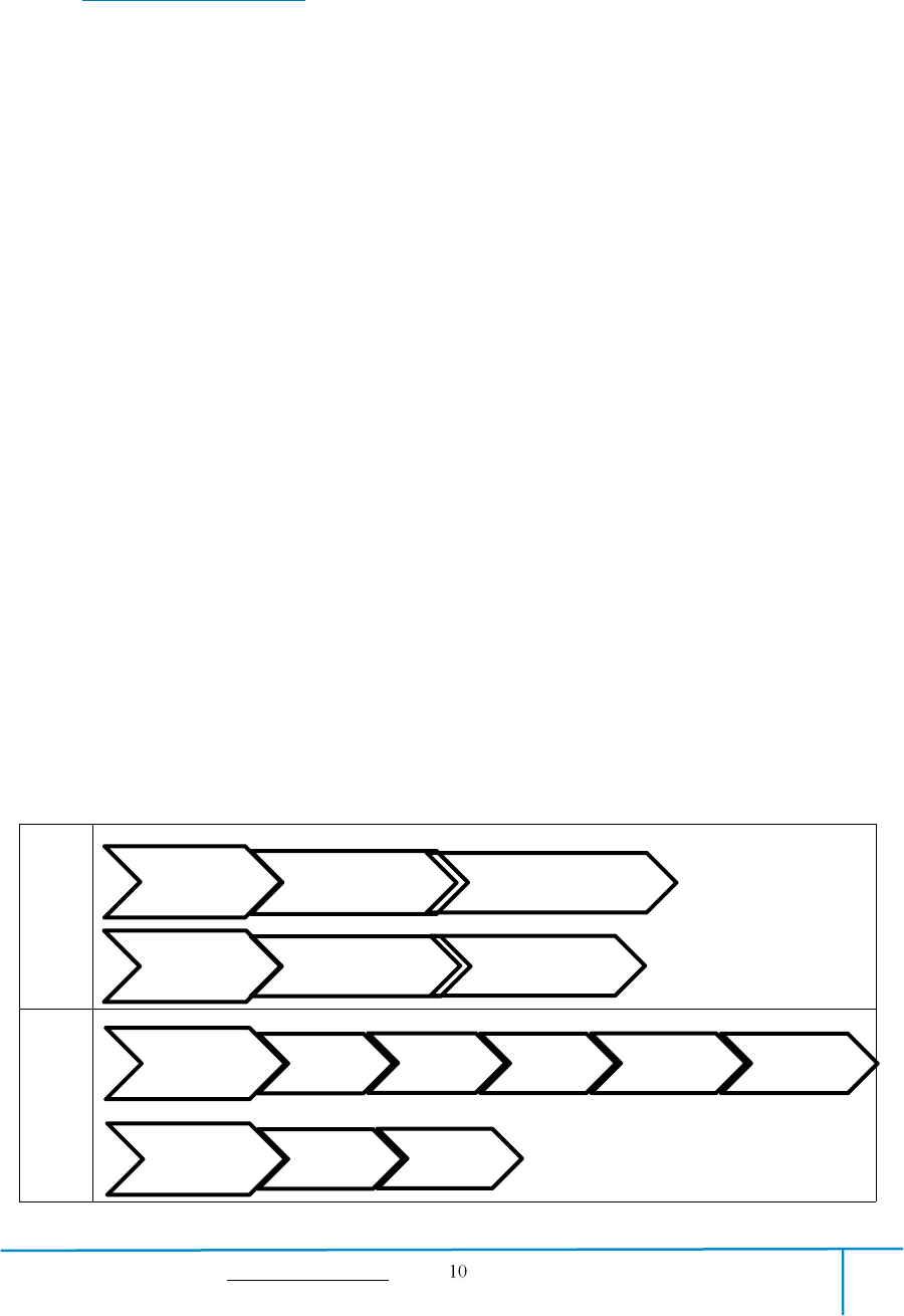
1.1.4 Basic 3D Printing Process:
First
Print
Daily
Print
Install printer
Printer Unboxing
Accessories check
Filament Loading
Install software
Install software
Start software
Distribute
print jobs
Print model
Acquire
model
Load in
model
Adjust
model
Set printing
parameters
After print
Processing
Remove
supports
Take down
model
GuiderIIS User Guide | www.flashforge.com 400-699-1063
Chapter 2: About GuiderIIS
2.1 About Your GuiderIIS
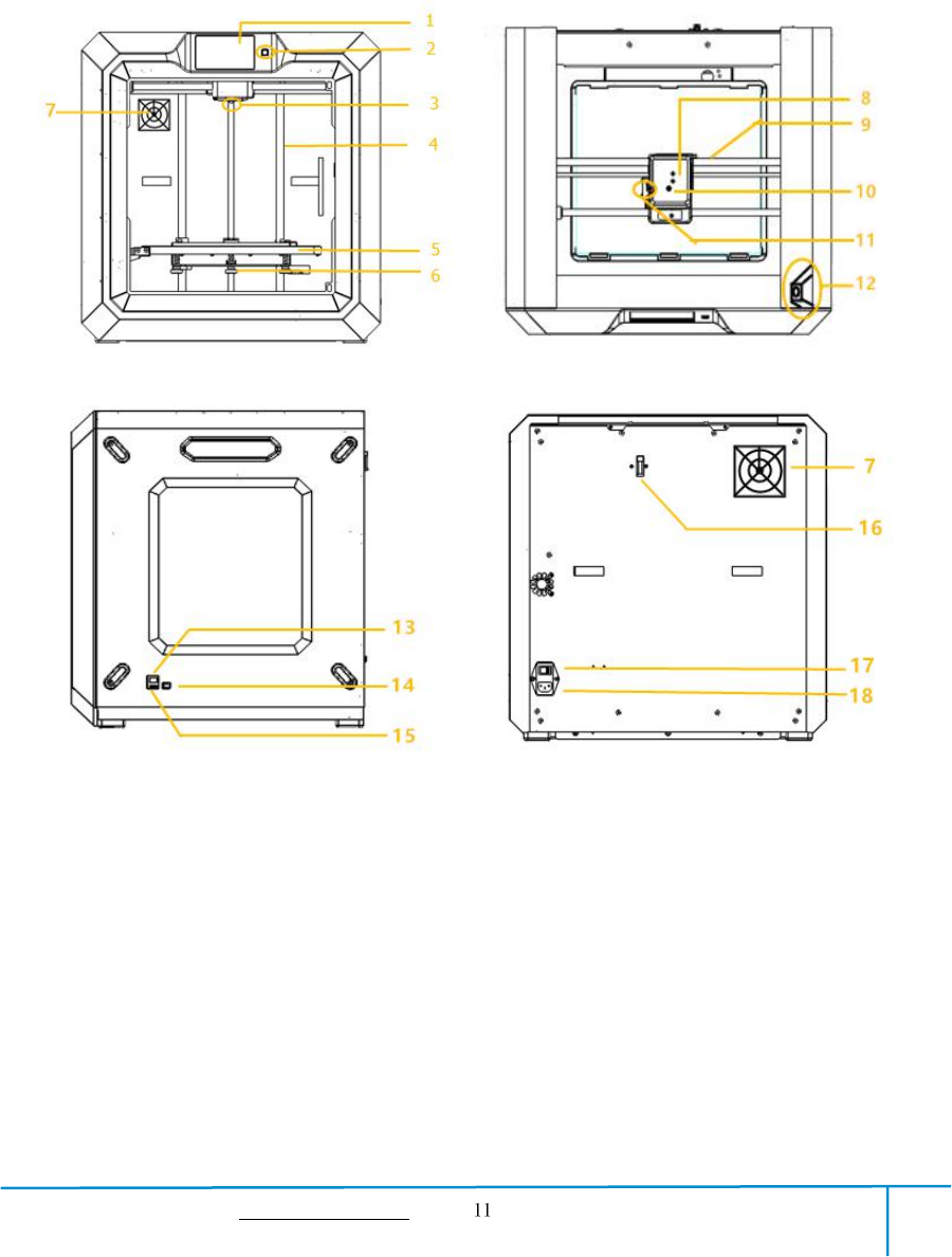
2.1.1 Views
Front Top
Right Back
1. Touch screen
2. Touch screen button
3. Nozzle
4. Z-axis guide rod
5.Build plate
6.Leveling knob
13.Ethernet input
14.USB cable input
15.USB stick input
16.Filament detector
17.Power switch
18.Power input
7.Filter fan
8.Extruder
9.X-axis guide rod
10.Filament intake
11.Spring presser
12.Camera

GuiderIIS User Guide | www.flashforge.com 400-699-1063
2.1.2 Terms
Build Plate
The surface on which the Guider Ⅱ builds an object.
Build Tape
The blue tape that covers Guider Ⅱ’s build plate so that
the object can stick to the build plate well.
Build Volume
The three dimensional amount of space that an object
will use once it is completed. The largest build volume
of GuiderIIS is 280*250*300 mm.
Leveling Knobs
Knobs under the build platform that are used for
adjusting the distance between the nozzle and build
plate.
Extruder
The device that draws the filament from the spool,
melts it and pushes it through a nozzle into the build
plate.
Nozzle
Also called “print head”, which located at the bottom
of the extruder where heated filament is squeezed out.
Cooling Fan
To cool the outer assembly of the extruder and gear
motor.
Filament Intake
An opening located at the top of the extruder.
Filament Guide Tube
A black plastic piece that guides the filament from the
filament box to the filament intake.
Filament Cartridge
A specific box for placing FlashForge filament.
Solid Glue Stick
A solid adhesive used for making the model stick to the
build plate firmly.
Unclogging Pin Tool
A tool that used for cleaning and unclogging the
extruder.
Stamping Wrench
A tool that used for seizing the nozzle’s metal cube.

GuiderIIS User Guide | www.flashforge.com 400-699-1063
2.1.3 Reference
Name
Guider Ⅱ
Number of Extruder
1
Print Technology
Fused Filament Fabrication(FFF)
Screen Size
5.0’’ color IPS Touch Screen
Build Volume
280*250*300mm
Layer Resolution
0.05 - 0.4mm
Build Accuracy
±0.2mm
Positioning Accuracy
Z axis 0.0025mm; XY axis 0.011mm
Filament Diameter
1.75mm(±0.07)
Nozzle Diameter
0.4mm
Print Speed
10~200 mm/s
Software
FlashPrint、Support Simplify3D
Support Formats
Input:3MF/ STL/OBJ/FPP/BMP/PNG/JPG/JPEG
Output:GX/G
OS
Win xp/Vista/7/8/10、Mac OS、Linux
Device Size
490*550*560mm
Net Weight
30Kg
AC Input
Input: 100V-240VAC, 47-63Hz Power: 500W
Connectivity
USB cable, USB stick, WiFi, Ethernet, Polar Cloud
Camera
1, Inside the corner between front and right board
Filter Fan
1, On the backboard
GuiderIIS User Guide | www.flashforge.com 400-699-1063
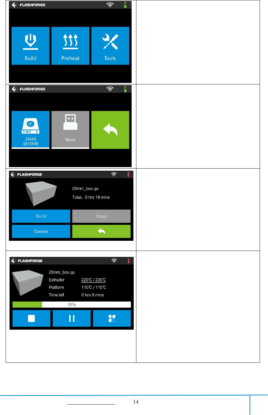
2.1.4 Interface Menus
Build
Read the print file from
The local memory card
The USB stick
Back
Select the target print file among the list
Build: To begin printing.
Copy: To copy the files to the local
memory card from the USB stick.(The
button is not available while printing from
local memory card )
Delete: To delete the print file.
Back
Print interface
Abort: To abort the print job.
Pause/Resume: To suspend or resume the
print job.
Tools:To check status or modify settings
during printing: build time, Z axis, filament
used, printing speed, light status, change
filament.
Extruder temperature: Can be changed
during printing.
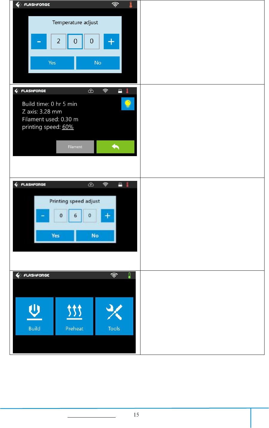
GuiderIIS User Guide | www.flashforge.com 400-699-1063
To set extruder temperature during printing:
After extruder temperature has reached
target temperature, temperature figure will
be underlined in print interface,
Tap [Yes] to save the setting while tap [No]
to cancel the setting.
Tools in print interface
Printing speed: To change printing speed
during printing by tapping the underlined
speed figure.
Light bulb: To turn on/off the light.
Filament: To change filament during
printing. (Note: You need to suspend the
printing operation first)
Cancel: To end the tool orders and return
to the print interface.
To set the printing speed during printing
Tap [Yes] to save the setting while tap [No]
to cancel the setting.
Preheat
GuiderIIS User Guide | www.flashforge.com 400-699-1063
Tap the [Preheat] button to enter the
preheat interface. Tap the [Start] button to
heat up to the setting temperature.
The default temperature is 220℃.
Tap the temperature display bar to set the
temperature.
To set the preheat temperature.
Tap [Yes] to save the setting while tap [No]
to cancel the setting.
The picture displays the preheat interface. It
shows the actual temperature and the target
temperature. Tap the [Abort] button to abort
the preheat job.
Tools
Tap [Tools] to enter tool options.
Filament: To load/unload the filament.
Level: To adjust the build plate.
Home: To make the X, Y and Z axes back
to the zero point.
Manual: To manually adjust the positions
of X, Y and Z axes.
Setting: To implement relevant function
setups.
Status: The check the real-time status of
the printer.
About: Information about the printer.
Back
GuiderIIS User Guide | www.flashforge.com 400-699-1063
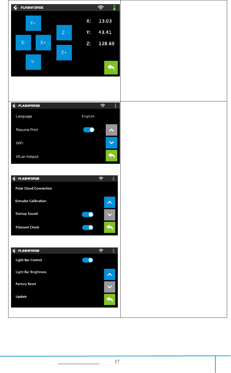
Manual adjustment
Y+: The extruder moves to the zero point,
that is, the back of the machine
Y-: The extruder moves to the direction
opposite to the Y+.
X+: The extruder moves to the zero
points, that is, to the right direction
X-: The extruder moves to the direction
opposite to the X+.
Z+: The build plate elevates.
Z-: The build plate descends.
Back
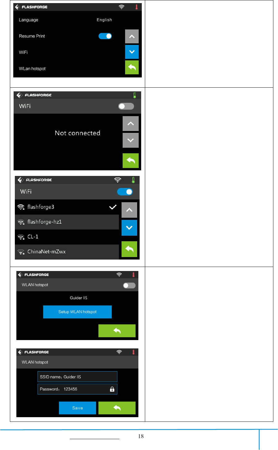
Tap [Setting] to enter the setting interface
Language: To set the display language
Resume Print: Resume print after
restarting Guider IIS
WiFi: To turn on/off the WiFi
WLan hotspot: To turn on/off the WLan
hotspot.
Polar Cloud Connection: To turn on/off
the Polar Cloud Connection.
Extruder Calibration: To adjust the initial
distance between the extruder and the build
plate.
Startup Sound: To turn on/off the Startup
Sound.
Filament Check: To turn on/off the
filament check
Light Bar Control: To turn on/off the
light bar control.
Light Bar Brightness: To adjust the light
bar brightness.
Factory Reset: Return to factory setting
Update: To update the firmware version.
Back
GuiderIIS User Guide | www.flashforge.com 400-699-1063
Turn on [Resume Print]
Left picture showed is the [Resume Print]
turned on status. If the printer is turned off
when current print job has not finished yet,
printer will continue and resume previous
printing job after restarted.
(Note: If [Resume Print] is turned off, this
function will not apply. )
WiFi:
Turn on WiFi: Turn on the WiFi, release
the WiFi hotspot and set the WiFi on
computer
Back
WLan hotspot
OFF/On: To turn on/off the Wlan hotspot.
Setup Wlan hotspot: To set the SSID and
password.
SSID: The name of hotspot.
Password: The password of hotspot.
Save: To save the setting.
Back
GuiderIIS User Guide | www.flashforge.com 400-699-1063
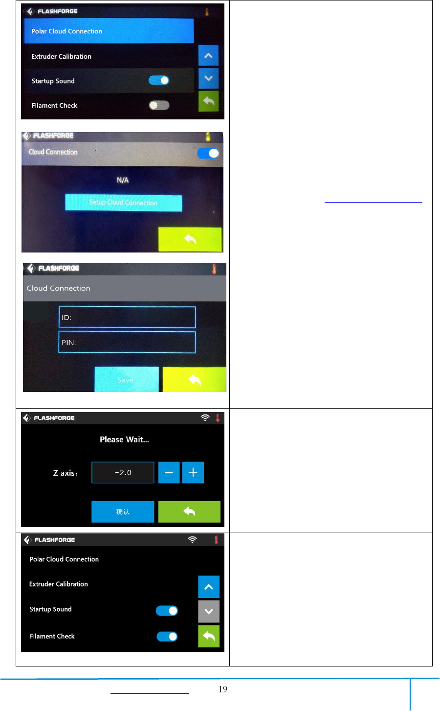
Polar Cloud Connection:
Cloud Connection: To turn on/off the polar
cloud connection.
Setup Cloud Connection: To set cloud
connection ID and PIN which have already
been registered on: https://polar3d.com
ID: The email address of your Cloud
account.
PIN: The PIN code of your Cloud account.
Save: To save the setting.
Back
(Note: To use polar cloud printing function,
you need to connect the printer to internet
with WiFi or Ethernet Cable first)
Extruder Calibration:
(not recommended for customers to operate)
To adjust the initial distance between the
extruder and the build plate by tapping
[-]and[+]. The proper distance may be one
ordinary paper’s thickness.
Turn on [Filament Check]:
Left picture showed is the [Filament
Check] turned on status.
Filament abnormal status will be detected
when filament is used up or suspended.
[Filament Check] function should be used
with filament in the filament cartridge.This
function is invalid if using filament out of
the cartridge.
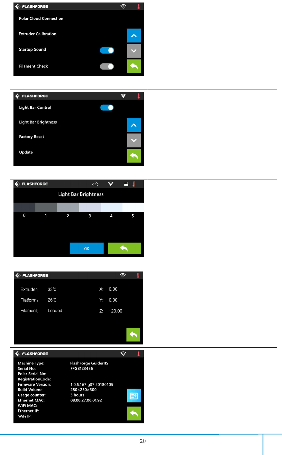
GuiderIIS User Guide | www.flashforge.com 400-699-1063
Turn off [Filament Check]:
Left picture showed is the [Filament
Check] turned off status.
Filament abnormal status won’t be detected
when filament is used up or suspended.
Turn on/off [Startup Sound]:
Tap to turn on/off the sound when restart
the printer.
Light Bar Control: To turn on/off the
light bar control.
Light Bar Brightness: To click and select
different light bar brightness.
Factory Reset: Return to factory setting
Update: To update the firmware version.
Back
Light Bar Brightness: To click and select
different light bar brightness.
Status:
It displays the real-time status of the
extruder temperature and other details.
About:
It displays the basic information about the
device.
GuiderIIS User Guide | www.flashforge.com 400-699-1063
Chapter 3:Unpacking
(reference video:Unpacking)
This chapter will present you the whole unpacking procedure of GuiderIIS 3D
printer.(Note: Make sure you read the whole unpacking guide)
3-1
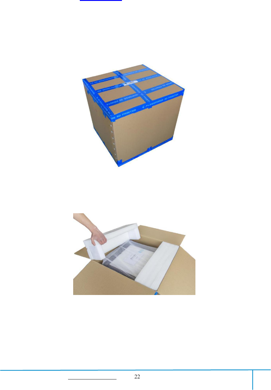
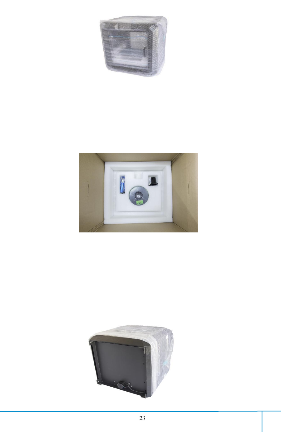
(3-1) Place the packaging box on a clean work surface.
(3-2)Open the box, take out the two foams and then lift your Guider ⅡS out of the
box.
3-2
GuiderIIS User Guide | www.flashforge.com 400-699-1063
(3-3) Your Guider ⅡS is wrapped by packaging materials, remove these materials step
by step.
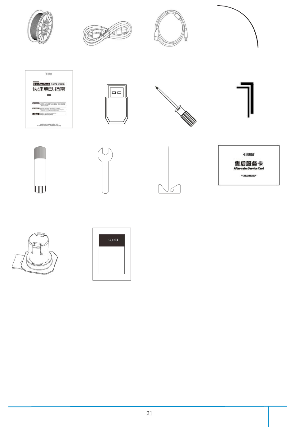
(3-4) In the bottom of the carton , you can see a spool of filament, a spool holder, a
Power Cable, a USB Cable, one Filament Guide Tube, a glue stick and a tool
bag( USB stick*1, Allen wrenches*2, stamping wrench*1, unclogging pin tool*1,
grease*1 and screwdriver*1).
3-3
3-4
GuiderIIS User Guide | www.flashforge.com 400-699-1063
Remove the side protective foam sheets.
(3-5) Remove the bag to unveil the Guider ⅡS
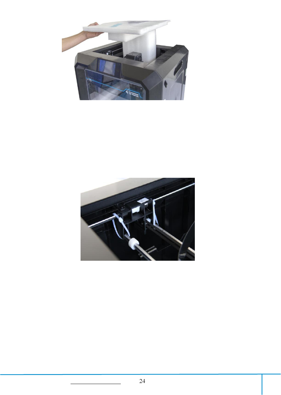
(3-6)Take out the top foam from the printer, on the top foam sheet, you can see one
Quick Start Guide and a After-sales service card.
(3-7)Cut off four ribbons that used for fixing the guide rod. Then slide the extruder
to make sure the extruder is in good condition.
3-6
3-7
GuiderIIS User Guide | www.flashforge.com 400-699-1063
Chapter 4: Hardware Assembly
Your GuiderIIS has been installed before leaving factory, you can start up the
GuiderIIS for printing after mounting the filament spool and completing leveling.
4.1 Filament Installation
4-1
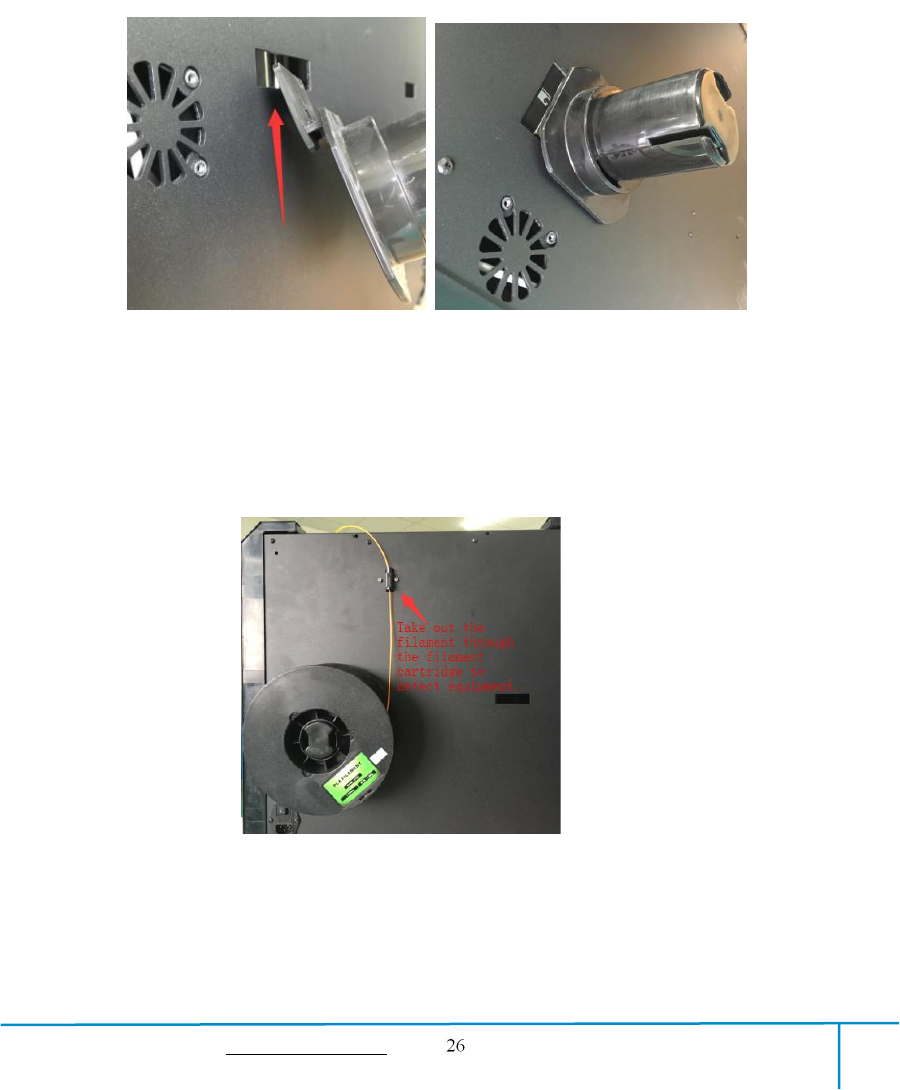
(4-1) The filament cartridge is at the rear of GuiderIIS. Lift the cartridge out of the
Guider ⅡS.
4-2
(4-2) Take out the filament and thread it through the filament detecting equipment.
(Note: The filament should feeds from the bottom of the spool towards the top )
Filament Detecting
Equipment in the black.
GuiderIIS User Guide | www.flashforge.com 400-699-1063
4.2 Printer Start-up
4-3
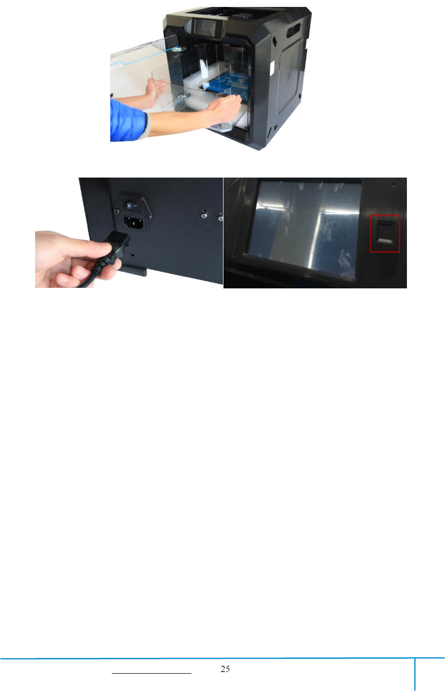
(4-3)Insert the power supply into the power input on the back of the GuiderIIS and
plug the power cord into an electrical outlet.
4.3 Loading Filament
For stable filament loading and proper device protection, you need to install the
filament guide tube properly.
4-4
(4-4) Take out the filament guide tube, thread the filament from Filament
Detecting Equipment
GuiderIIS User Guide | www.flashforge.com 400-699-1063
4-5
(4-5) Insert the filament from the filament guide tube into the filament intake.
Next, we will load the FlashForge filament.(Note: Please lower the build plate to
increase the distance between the nozzle and build plate to 50mm at least for
avoiding nozzle jam.)
(4-7) Tap [Tool].
图4-6
4-8
4-7
GuiderIIS User Guide | www.flashforge.com 400-699-1063
(4-8) Tap [Filament]--[Load]
4-9
(4-9)
After the extruder’s temperature reaches 220℃, the printer will sound a beep to
prompt you to load the filament into the extruder.
4-10
(4-10)
Insert the filament into the extruder at an upright angle. Then the filament will
be drawn through the extruder. Do not tap [Cancel] until the filament load the extruder
steadily.
4.4 Unloading Filament
4-11
GuiderIIS User Guide | www.flashforge.com 400-699-1063
(4-11) Tap [Tool]-[Unload] and the extruder starts heating up.
4-12
(4-12) After the extruder reaches 220℃, the printer will sound a beep to prompt you to
unload the filament from the extruder. Press the spring presser, press down the
filament for about three seconds and gently pull the filament out.
Note: Do not pull out the filament with force as it will damage the gears. If the
melted filament has cooled down in the extruder, please repeat the steps above.
GuiderIIS User Guide | www.flashforge.com 400-699-1063
Chapter 5: Build Plate Leveling
GuiderIIS creatively adopts three-point intelligent leveling system, which will give
clear and comprehensive feedback to users. There are three spring-loaded knobs under
the build platform. The distance between the plate and nozzle increases while
tightening the knobs. On the contrary, the distance reduces.
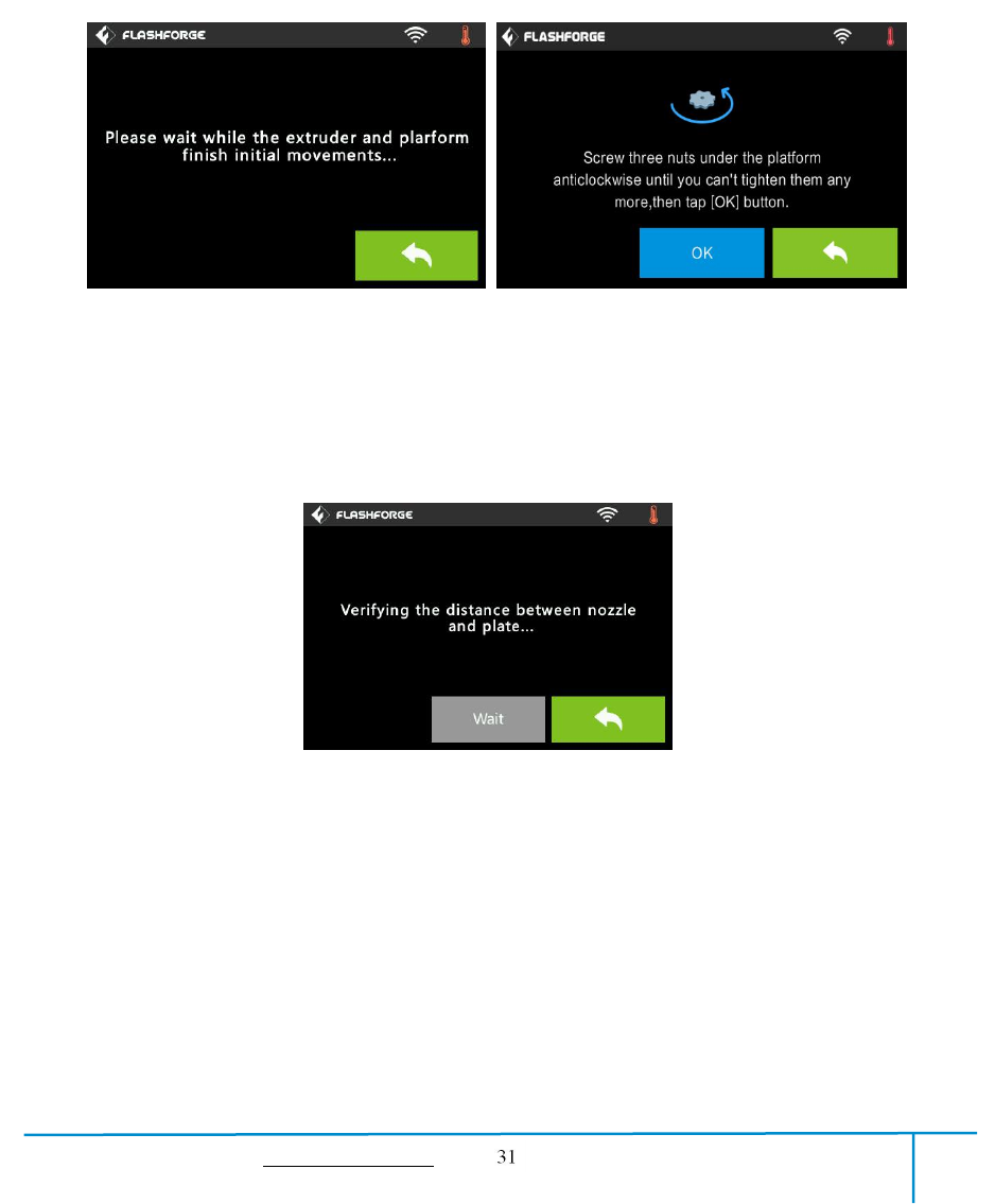
(5-1) Tap [Tools] - [Level] on your GuiderIIS touch screen. Please wait while the
extruder and platform finish initial movements. After that, operate according to the
guide on the touch screen.
5-2
(5-2) After tapping [Yes], the extruder starts to move towards the first point and the
plate moves up and down to verify the distance between nozzle and plate.
5-1
GuiderIIS User Guide | www.flashforge.com 400-699-1063
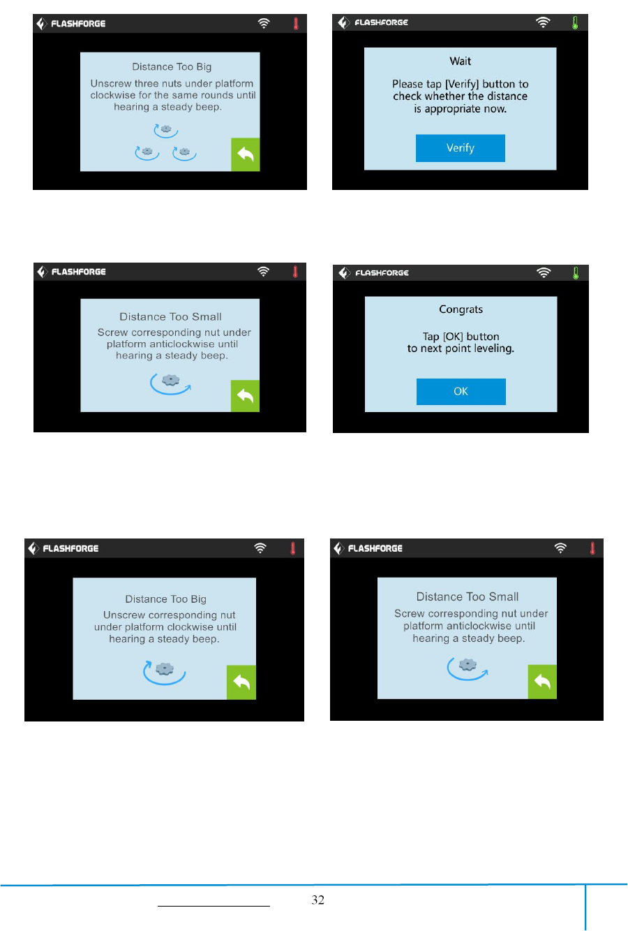
5-3
(5-3) When it shows that the distance is too big, please unscrew all three nuts under
platform clockwise for the same rounds until hearing a steady beep and the [Verify]
button appears.
5-4
(5-4) If the distance is appropriate, tap [OK] to second point leveling. If still not,
please follow the prompts to adjust the first point screw again till you see [OK] button.
5-5
(5-5) Repeat steps according to the prompts on the touch screen to complete second
and third points leveling and then finally Tap [Finish] to exit.
Leveling operating has completed!
GuiderIIS User Guide | www.flashforge.com 400-699-1063
Chapter 6: About Software
This chapter talks about the basic function of FlashPrint. For more information about
advanced function, you can browse our website www.FlashForge.com.
6.1 Software Installation
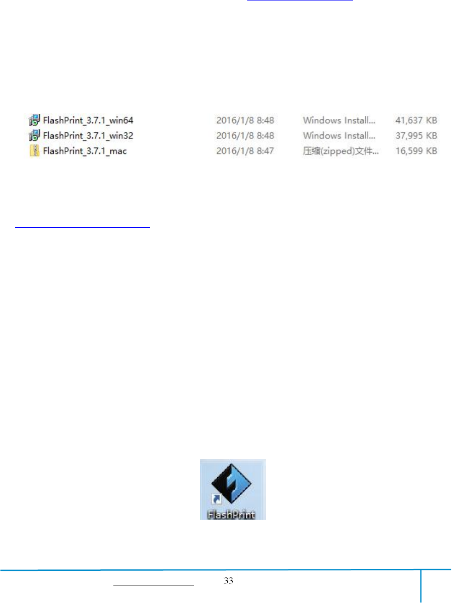
6.1.1 Software Acquisition
Method 1: To get the installation package from the USB stick in the toolkit.
Method 2: Open the link below to download the installation package:
http://www.FlashForge.com
Steps:
Support---Downloads---FlashPrint---Choose the software version---Download
6.1.2 Software Installation and Start-up
1. Decompress the zipped file or start the installation program, and then install the
software according to the direction.
2. Start the software with the start menu shortcut or by clicking the software icon.(See
6-1)
6-1
GuiderIIS User Guide | www.flashforge.com 400-699-1063
6.2 Exploring FlashPrint
6. 2.1 Machine Type Selection
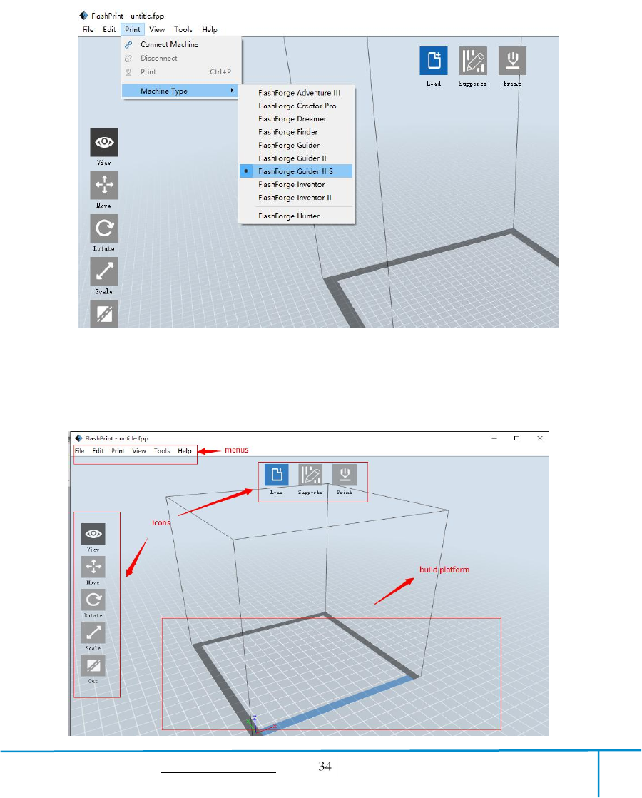
! After starting FlashPrint, you need to select the target machine type first.
When you start FlashPrint, a dialog box will pop up. Just select FlashForge Guider ⅡS
in the machine type list and click [OK]. You can also change the machine type via
clicking [Print]--[Machine type]. See graphic 6-2:
6-2
6.2.2 Software Introduction
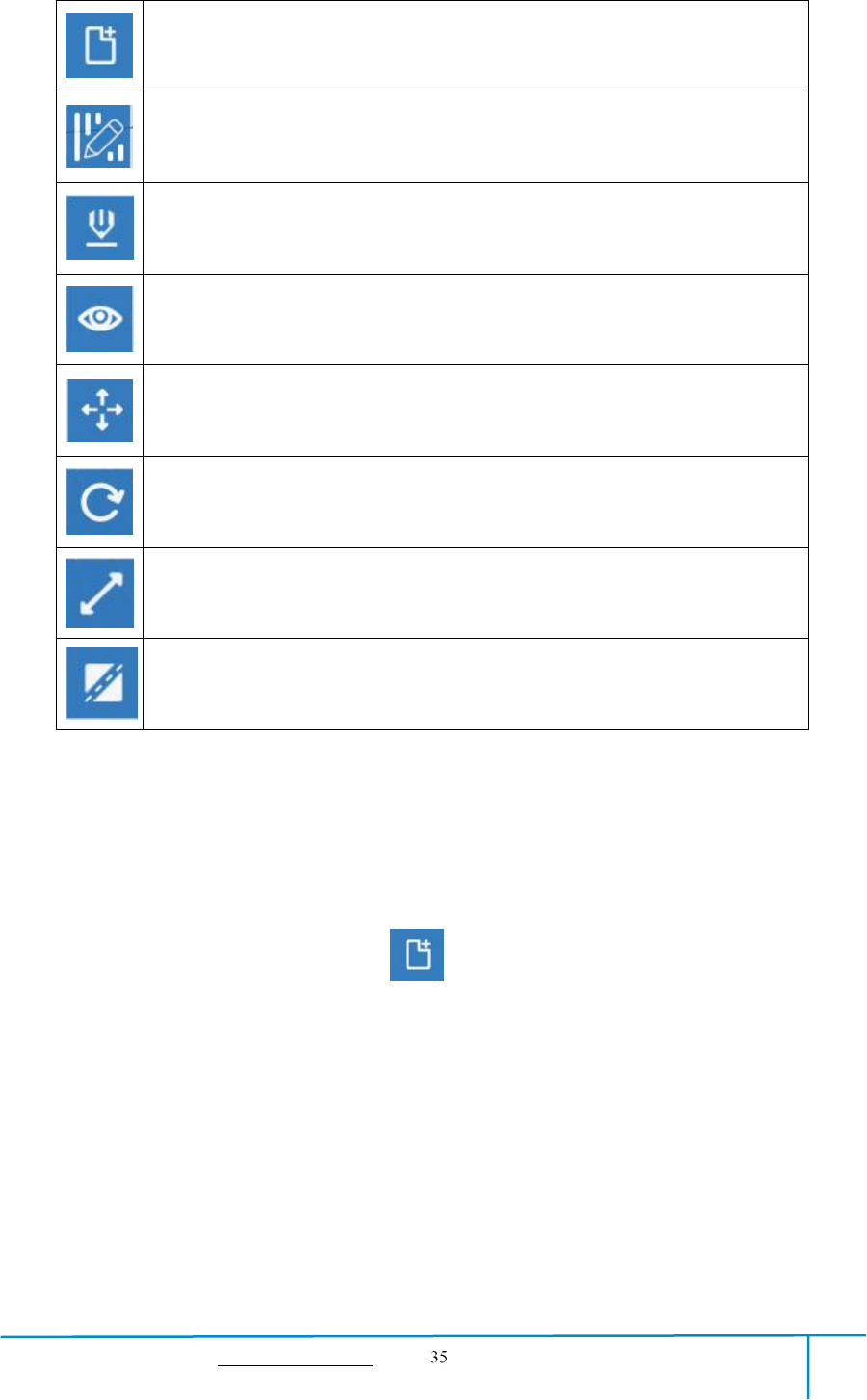
GuiderIIS User Guide | www.flashforge.com 400-699-1063
Load files.
Enter the support edit mode
Print it directly with your GuiderIIS or export to your USB Stick
View FlashPrint home screen from one of six viewing angles
Move model around on XY-plane; shift+click to move along Z axis
Turn and rotate your model
Scale the size of your object
Cut model into several parts
6.2.3 Loading
You can load a model file or Gcode file into your FlashPrint by the following six
methods:
Method 1: Click the [Load] icon on the main interface. Then select the
object file.
Method 2: Select the file for loading and drag the file to the main interface of the
software.
Method 3: Click [File]--[Load File]. Then select the object file for loading.
Method 4: Click [File]--[Examples]to load the example files
Method 5: Click [File]--[Recent Files]to load the files opened recently.
Method 6: Select and drag the target file to the icon of FlashPrint.
GuiderIIS User Guide | www.flashforge.com 400-699-1063
Note: .STL, .OBJ, and .FPP,ways to store 3D models, are supported by FlashPrint
for editing.
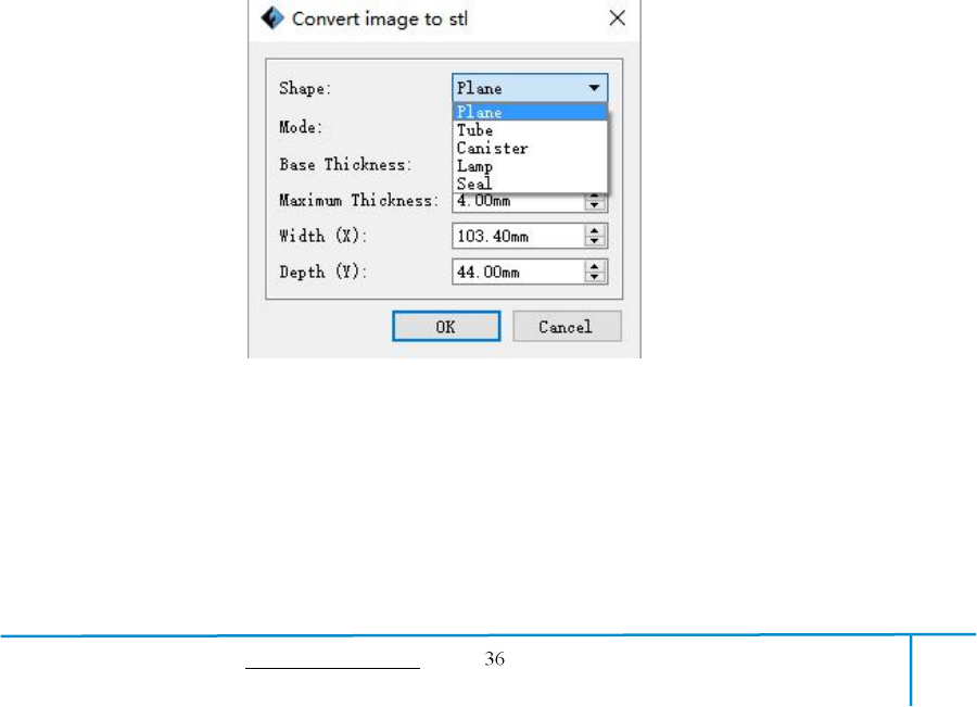
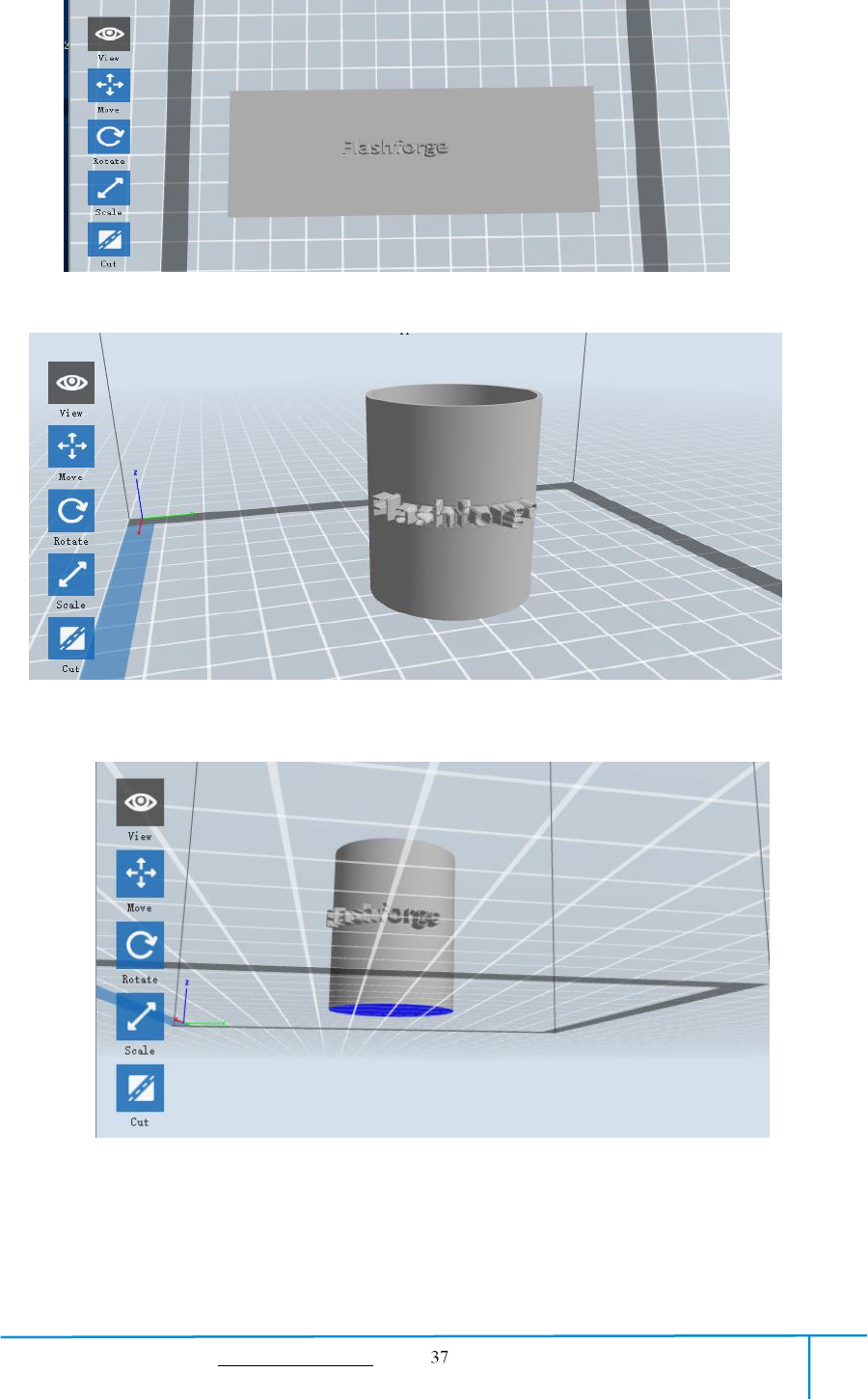
Generating Rilievo
Load a png, jpg, jpeg, bmp picture file into the FlashPrint. And the following dialogue
box (6-3) will pop up. The setting box includes settings for shape, mode, maximum
thickness, base thickness, bottom thickness, width, height, top diameter and bottom
diameter.
Shape: including plane, tube, canister and lamp.
Mode: including “darker is higher” and “lighter is higher”.
Maximum thickness: Z value of the model
Base thickness: The minimum raft thickness and the default value is 0.5mm
Width: X value of the model
Depth: Y value of the model
Bottom thickness: For tube, canister and lamp to set up bottom thickness
Top diameter: For tube, canister lamp and seal to set up the top diameter
Bottom diameter: For tube, canister, lamp and seal to set up the bottom diameter
6-4

GuiderIIS User Guide | www.flashforge.com 400-699-1063
Method 2: Hold down the mouse wheel and scroll up and down.
Method 3: Hold down the Shift key, hold down the right mouse button and drag.
●Rotate
Click the [View] icon and then you can rotate the object by the following two
methods:
Method 1. Hold down the right mouse button and drag.
Method 2. Hold down the Shift key, hold down the left mouse button and drag.
●Scale
Rotate the mouse wheel to enlarge or shrink the build plate.
②Set View
Allow users to view the object on the build plate. Six views are under the view menu,
that is, bottom view, top view, front view, back view, left view and right view.
Method 1: Click the the [View] button, there are six views in the drop- down list
Method 2: Click the the [Look] icon on the left, click it again and a submenu
will appear with six views for selecting.
③Reset View
Allow users to reset views by the following two methods:
Method 1: Click the [View] menu and select [Home View]
Method 2: Click the [View]button on the left, click it again and you will see the
viewing options, you can click [Reset].
④Show Model Outline
Click [View]--[Show Model Outline], it will highlight the yellow border of the object

GuiderIIS User Guide | www.flashforge.com 400-699-1063
⑤Show Steep Overhang
Click [View]--[Show Steep Overhang]. When the intersection angle between the
model surface and horizontal line is within the overhang threshold value, the surface
has steep overhang and it becomes red in the software. Overhang threshold value
could be set as needed. The default value is 45 degree.
6.2.5 Move
Select the object and move the object by the following two methods:
Method 1: Click the [Move] icon on the left, hold down the left mouse button and
drag to adjust the location of the model in XY direction. Hold down the Shift key,
hold down the left mouse button and drag to adjust the location of the model in Z
direction. The distance and the direction of the movement shall be displayed.
Method 2: Click the [Move]button on the left and then enter the distance value. Click
[Reset]to reset distance values.
Note: Users shall click [Center] and [On Platform] after the location adjustment to
ensure the model(s) be within the build area and on the build platform. If a specified
position is needed, only click [On Platform].
6.2.6 Rotate
Select the target object and rotate the object by the following two methods:
Method 1: Click the [Rotate] icon on the left and three mutually perpendicular rings
appear around the object Click one ring and rotate on the present axis, you will see the
rotation angle and direction in the center of circle. In this way, you could make the
model rotate on X/Y/Z axis.
Method 2: Click the [Rotate] icon on the left, and then enter into rotating angel
values in X/Y/Z axes positioning. Click [Reset] to reset rotating angel values.
GuiderIIS User Guide | www.flashforge.com 400-699-1063
6.2.7 Scale
Select the target object and scale the object by the following two methods:
Method 1: Click the [Scale] icon on the left, hold down the left mouse button and
scale the model. The corresponding values will display near the object.
Method 2: Click the [Scale] icon on the left and then enter into scale values in X/Y/Z
axes positioning. Click the [Maximum] button to get largest size possible for building.
Click [Reset] to reset the size of model.
Note: If the [Uniform Scaling] radio button is clicked, it will scale the model in equal
proportion when changing value in any positioning of the model. Otherwise it will
only change the value of the corresponding positioning.
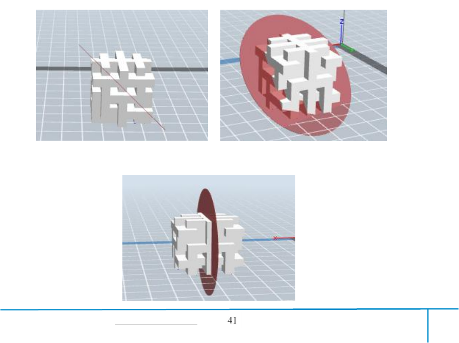
6.2.8 Cut
Left-click on the model to select it and double-click on the [Cut] icon to set the cut
plane. The direction and position are available for setting.
①Draw with Mouse
②X Plane
GuiderIIS User Guide | www.flashforge.com 400-699-1063
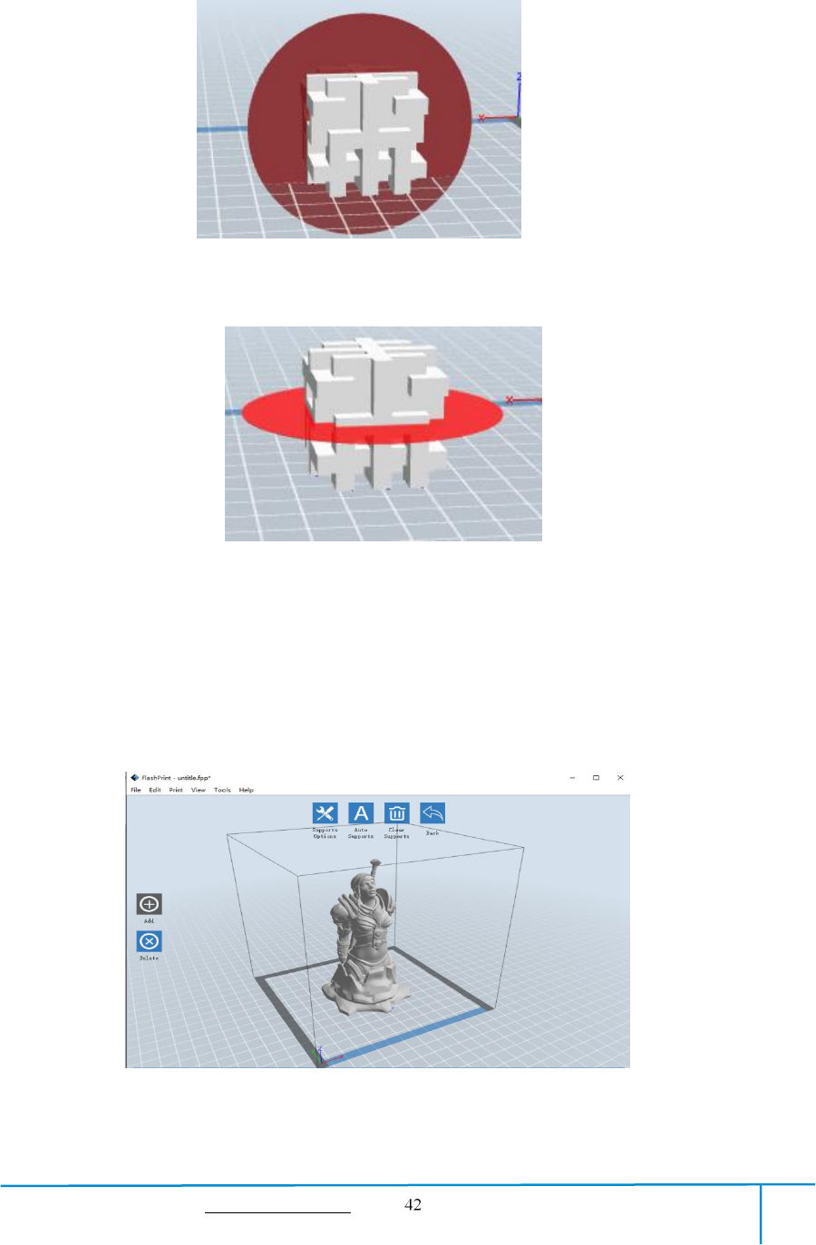
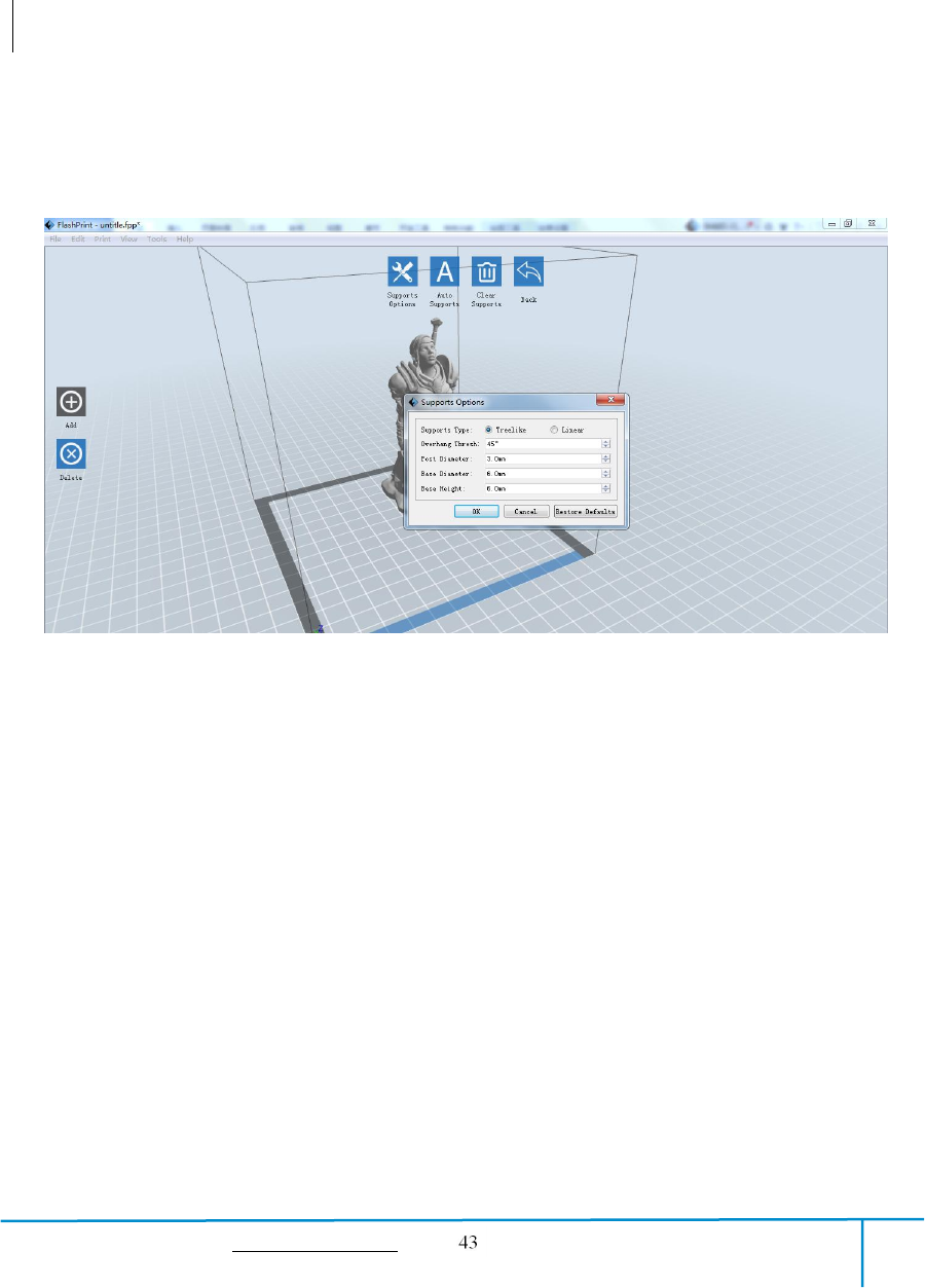
①Support Options
Click the Support Options, an option box will appear, supports options include
“treelike” and “linear”, when choose “treelike”, click [OK], then it will generate
treelike structure; when choose “linear”, click [OK], then it will generate linear
structure; if it is a model with supports, when you choose one of the supports options,
software will judge whether existing supports need to be deleted or not on the basis of
the type of existing support, and will pop up the corresponding prompt to let you make
the choice.
②Auto Supports
Click the [Auto Supports] button, the software will judge the position where supports
are needed and generate corresponding treelike or linear supports. If it is a model with
supports, the existing supports will be deleted and new supports will be generated.
③Add Supports
Supports will be added once clicking the [Add]button. Move the cursor to the
position where supports needed, left-click to choose the starting point of supports, hold
down the left mouse button and drag the mouse the supports preview will show up (if
support surface doesn’t need support or the support column angle is too large, will
6-11
GuiderIIS User Guide | www.flashforge.com 400-699-1063
highlight the support review). Loosen the left mouse button, if support column doesn’t
meet with model, then support will be generated on origin and terminal point (the
highlighted preview support won’t generate support structure )
④Clear Supports
Click [Clear Supports], all supports will be deleted. The operation can be repealed
via clicking [Undo]or pressing the shortcut key Ctrl+Z.
⑤Delete Supports
Supports will be deleted once clicking the [Delete]button. Move the cursor to the
supports needed deleting, current supports and its subnode support will be highlighted,
click the left mouse button to delete these highlighted support.
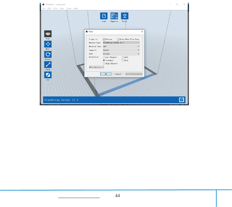
6.2.10 Print
①Preview: Choose to enter preview interface or not
②Print when slice done: Print or not when slice done
③Material type: Choose according to the type of model
④Supports: When print suspended structure models, support is necessary. Click
[supports] to create support part for the printing.

GuiderIIS User Guide | www.flashforge.com 400-699-1063
⑤Raft: This function will help the model to stick well on the platform.
⑥Wall: During dual color printing, this function will help to clear the leaking
filament of another extruder.
⑦Brim: Expand the outline of model’s bottom layers to a Brim which helps anchor
the edges of the model to the plate to avoid warping.
⑧Resolution:You have three resolution solutions (with default setting)to choose from,
high resolution is corresponding with slow printing speed, opposite for the low
resolution. For PLA printing, an extra solution “Hyper” is available.
⑨More options: Click [More options] to set for layer, shell, infill, speed and
temperature. Different resolution solution is corresponding to different defaults, click
[Restore Defaults] to back to default setting.
●Layer
a. Layer: Layer thickness of the printing model. With a small value, the surface
of the model will be smoother.
b. First Layer Height: This is the first layer of the model, which will affect the
sticking performance between the model and platform. Maximum is 0.4mm, usually
the default is OK.
c. Shell: Contains the outside shell value, capping layer value (under vase pattern,
top solid layer setting is invalid.)
● Perimeter Shells: Maximum is 10
a. Top Solid Layer: Maximum is 30, minimum is 1.
b. Bottom Solid Layer: Maximum is 30, minimum is 1.
● Infill
a. Fill Density means fill rate.
b. Fill Pattern is the pattern of filling shape which effects printing duration.

GuiderIIS User Guide | www.flashforge.com 400-699-1063
c. Combine Infill: You can select the layers for combining according to the layer
thickness. The combined thickness should not exceed 0.4mm. “Every N layers” is for all the
infills while “Every N inner layers” is only for inner infills, which generally can save print
time.
6-13
● Speed
a. Print Speed is the moving speed of the extruder. Generally, the lower speed is,
the better print you will get. For PLA printing, 80 is recommended.
b. Travel Speed is to control the moving speed of the extruder under
non-printing Status during work. For PLA printing, 100 is recommended.
Note: Modify parameters settings to get better prints as different models need different
parameters.
● Temperature
Extruder Temperature: Recommended extruder temperature is 220℃.
Note: Different temperatures have subtle influences in prints. Please adjust the
temperature according to the condition in order to get a good print.
Platform Temperature: To set the temperature of Platform.
● Others
Cooling Fan Control: Set up the time to turn on the cooling fan. You can
pre-set the height and make the cooling fan begin to work at the point.
Pause At Heights: Allows users to pre-set a height in which the print will
suspend automatically. The function usually applied when you want to change the
filament at a certain point. (6-14) Click [Edit], then you can add or remove a height.
GuiderIIS User Guide | www.flashforge.com 400-699-1063
6.2.11 File Menus
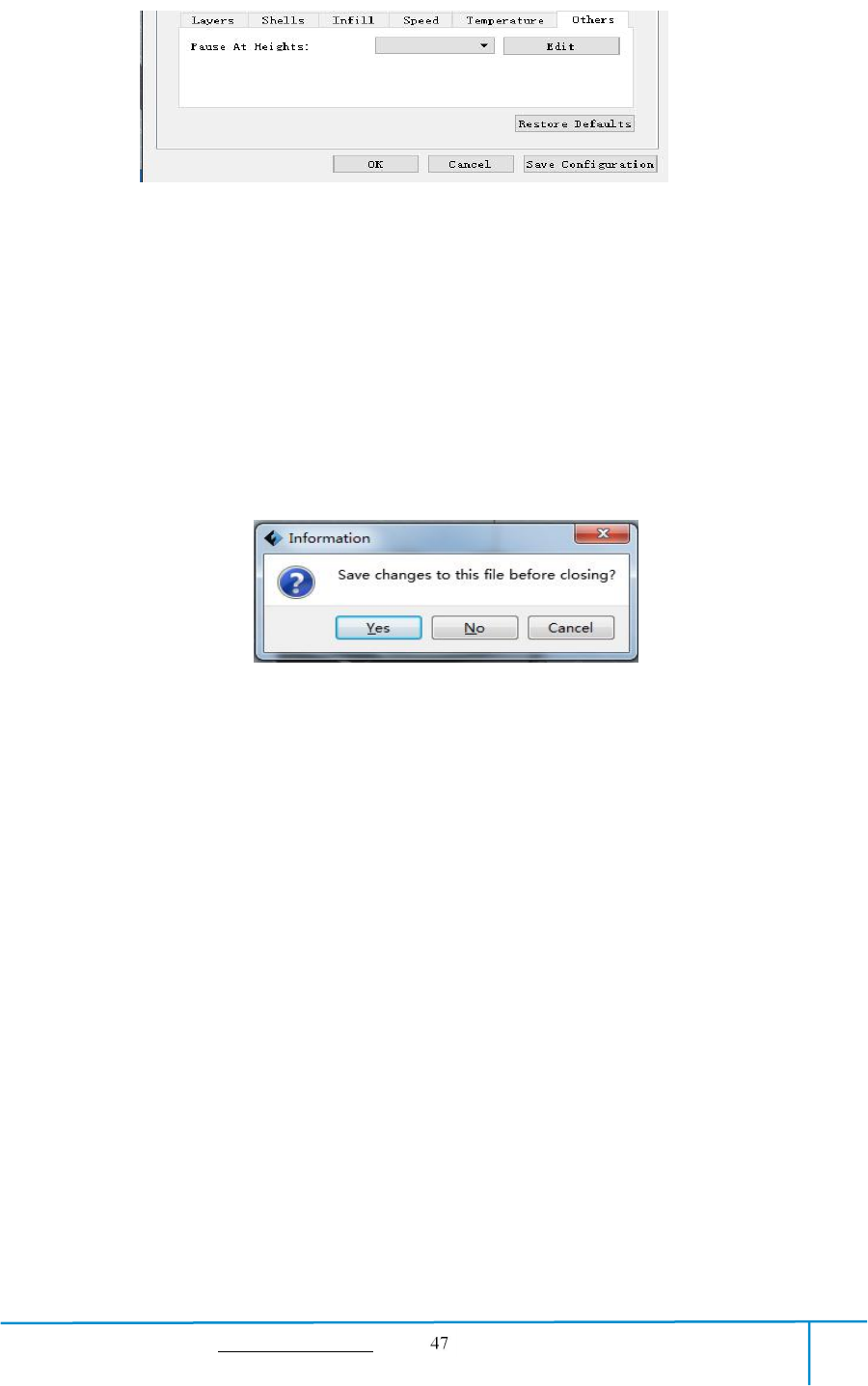
①New Project
Click [File]--[New Project]can build a blank project. If there is an unsaved
modification on previous project, then it will inform you whether the modification
needs to be saved or not. Click [Yes]will save the modification, while click [No]will
abandon it. If click [Cancel]or close tool tip, then will cancel the new project.
②Saving
After finishing the model edit and adjustment, there are two ways below to save all
models in the scene.
Method 1:
Click [File]--[Save Project] in the menu bar to save the file as a project file with the
“.fpp” suffix, all models in the scene (include support) are independent. After
reloading the files, extruder configuration information and model position will be the
same as the configuration during saving.
Method 2:
6-15
6-14
GuiderIIS User Guide | www.flashforge.com 400-699-1063
Click on [File]--[Save as...] to save the model as project file .fpp or .stl and .obj.
For .stl and .boj, models are integrated as one(include support part). If load it again,
only the position of the model was saved, not included the printing parameters.
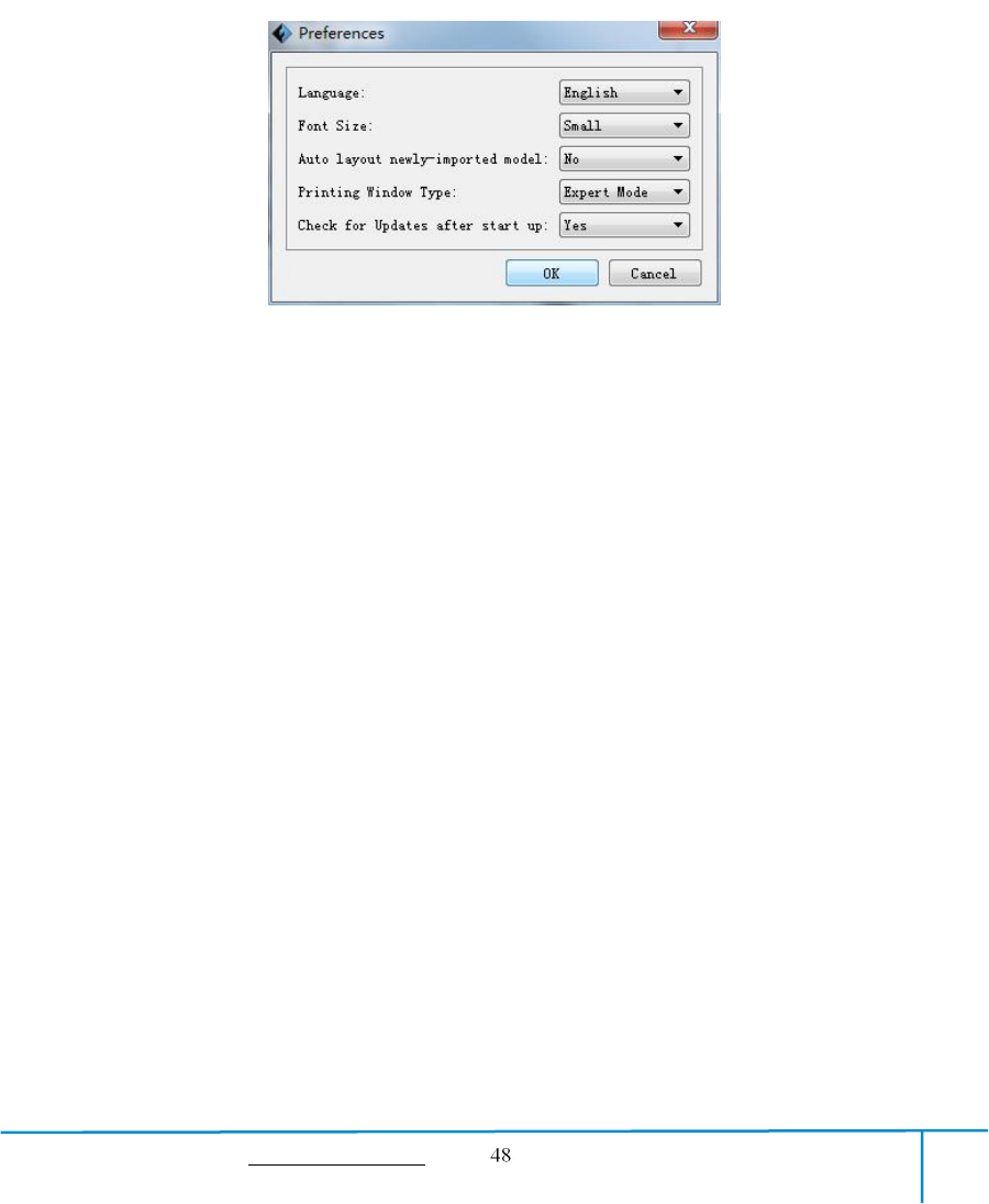
③Preferences
Click [File]--[Preferences], you can choose language and if needs detecting update
when start
●Language: The software supports several languages, namely, Chinese (simplified
Chinese and traditional Chinese), English, French, Korean, Japanese and so on.
●Font Size: Set the font size.
●Auto layout newly-imported model: Set Yes or No.
●Printing Window Type: Including Base Mode and Expert Mode
●Check for Update after start up: It is used to preset if it is necessary to activate the
online automatic update function, if choose yes, every time when you open software, it
can online detect if it is a new version software, once new version found, it will
reminds users to download and install new version firmware.
6.2.12 Edit Menus
①Undo
Allows users to undo the recent edits by the following two methods:
Method 1: Click [Edit]--[Undo].
Method 2: Press the shortcut Ctrl+Z.
②Redo
6-16

GuiderIIS User Guide | www.flashforge.com 400-699-1063
Allows users to redo the most recent edit you have undone to your model file by the
following two methods
Method 1: Click [Edit]--[Redo]
Method 2: Press the shortcut Ctrl+Y.
③Empty Undo-stack
To clean up the recorded operating steps so as to release the memory.
④Select All
By the following two methods, you could select all models in the scene. (When
models are too small to be seen or out of viewing scope, please click [Center] and
[Scale] buttons to adjust the model.)
Method 1: Click [Edit]--[Select All].
Method 2: Press the shortcut Ctrl+A.
⑤Duplicate
Select the object and duplicate the object through the following two methods:
Method 1: Click [Edit]--[Duplicate]
Method 2: Press the shortcut Ctrl+D
⑥Delete
Select the object and delete the object through the following two methods:
Method 1: Click [Edit]--[Delete]
Method 2: Press the shortcut Delete
⑦Auto Layout All
Click [Edit]--[Auto Layout All]after loading one or more than one models, all
models will be placed automatically as automatic placement rule.
⑧Repair Models
GuiderIIS User Guide | www.flashforge.com 400-699-1063
Click [Edit]--[Repair Models] to repair models.
⑨Supports
Click [Edit]--[Supports] to enter supports setting interface.
6.2.13 Print Menus
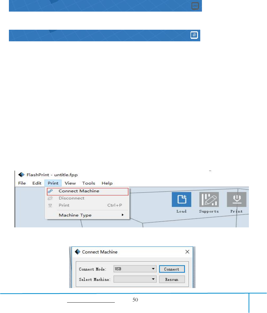
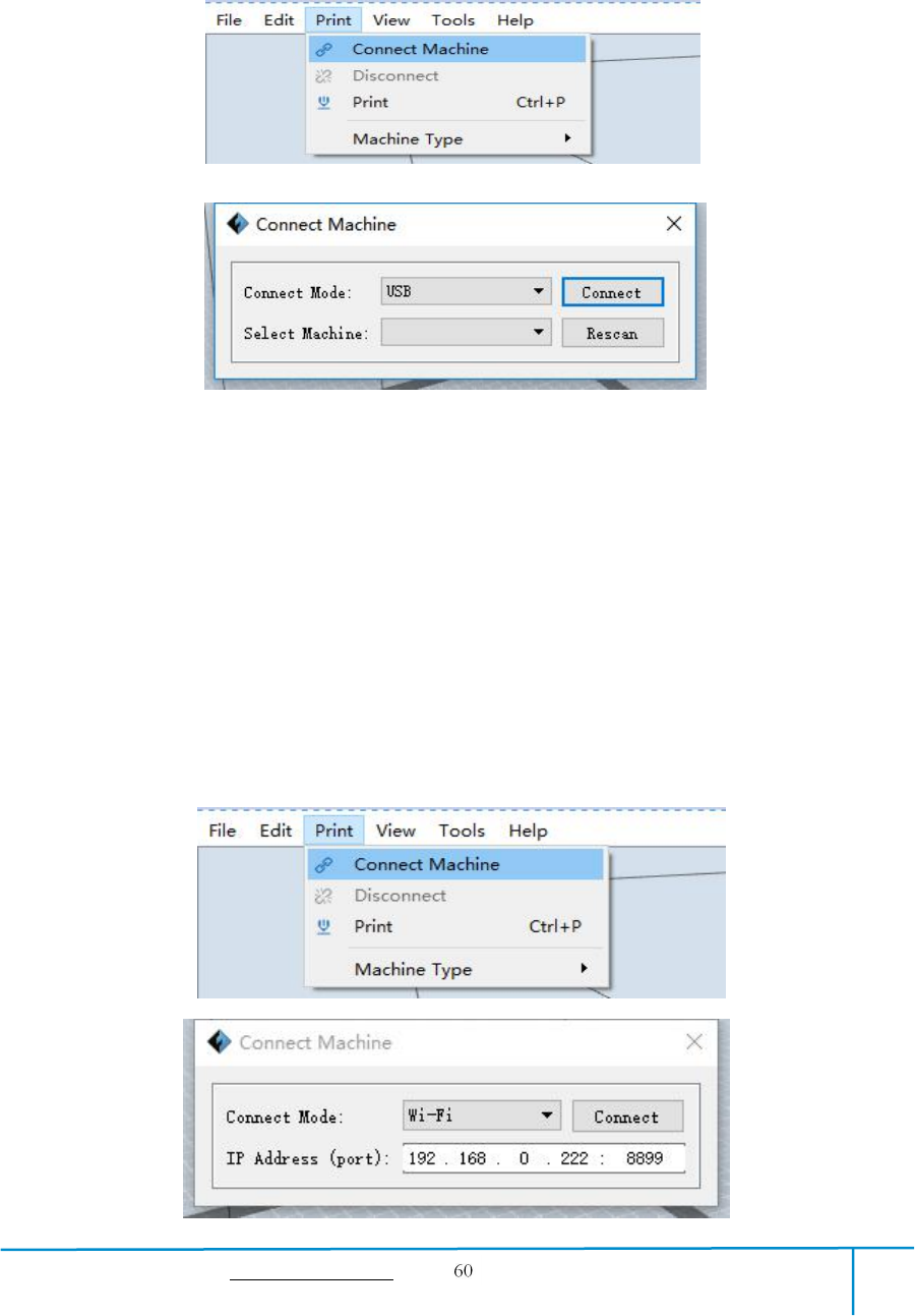
①Connect Machine
You can connect the Guider ⅡS with your PC via USB cable or WiFi or Ethernet Cable.
Note: The machine icon on the bottom right displays the connection status:
Connected
Disconnected
Method 1:Connect Via USB Cable
a. Connect your GuiderIIS with your PC via an USB cable.
b. Turn on your GuiderIIS and start FlashPrint.
c. Click [Print]--[Connect Machine],then select USB in the [Connection Mode]
option and select machine you want to connect in [Select Machine] option. If you can
not find your machine, click the [Rescan] button to scan your machine and select it.
Finally click [Connect] button to connect to the printer. If you still can not find your
machine after rescan, it means you haven’t installed the driver in the software.
GuiderIIS User Guide | www.flashforge.com 400-699-1063
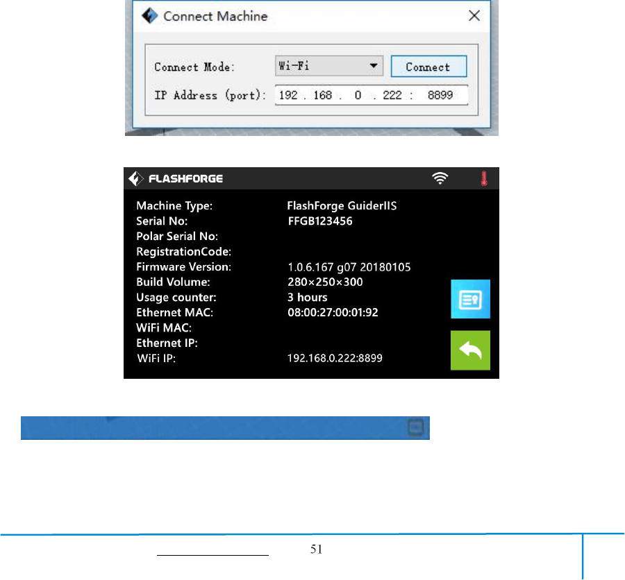
Method 2:Connect Via WiFi
①Connect Guider ⅡS with your PC under AP mode
a.Turn on your Guider ⅡS
b. Tap [Tools]-[Setting]-[WLan hotspot]-[WLan hotspot ON].
c. Click on the wireless network setting in your computer, and find the wireless
signal-“Guider ⅡS”. Click [Connect] to connect your computer with Guider ⅡS via
Wlan hotspot.
d. Click [Print]-[Connect Machine] on FlashPrint. Then the following dialog
box pops up. You need to select “Wi-Fi” in Connect Mode. Enter into the IP Address
shown on the interface and then click [Connect].
If successfully connected, you will see the following mark on the right corner.
②Connect Guider ⅡS with your PC under STA mode
a. Tap [Tools]-[Setting]-[WiFi]-[WiFi ON] to turn on the WiFi of Guider IIS and
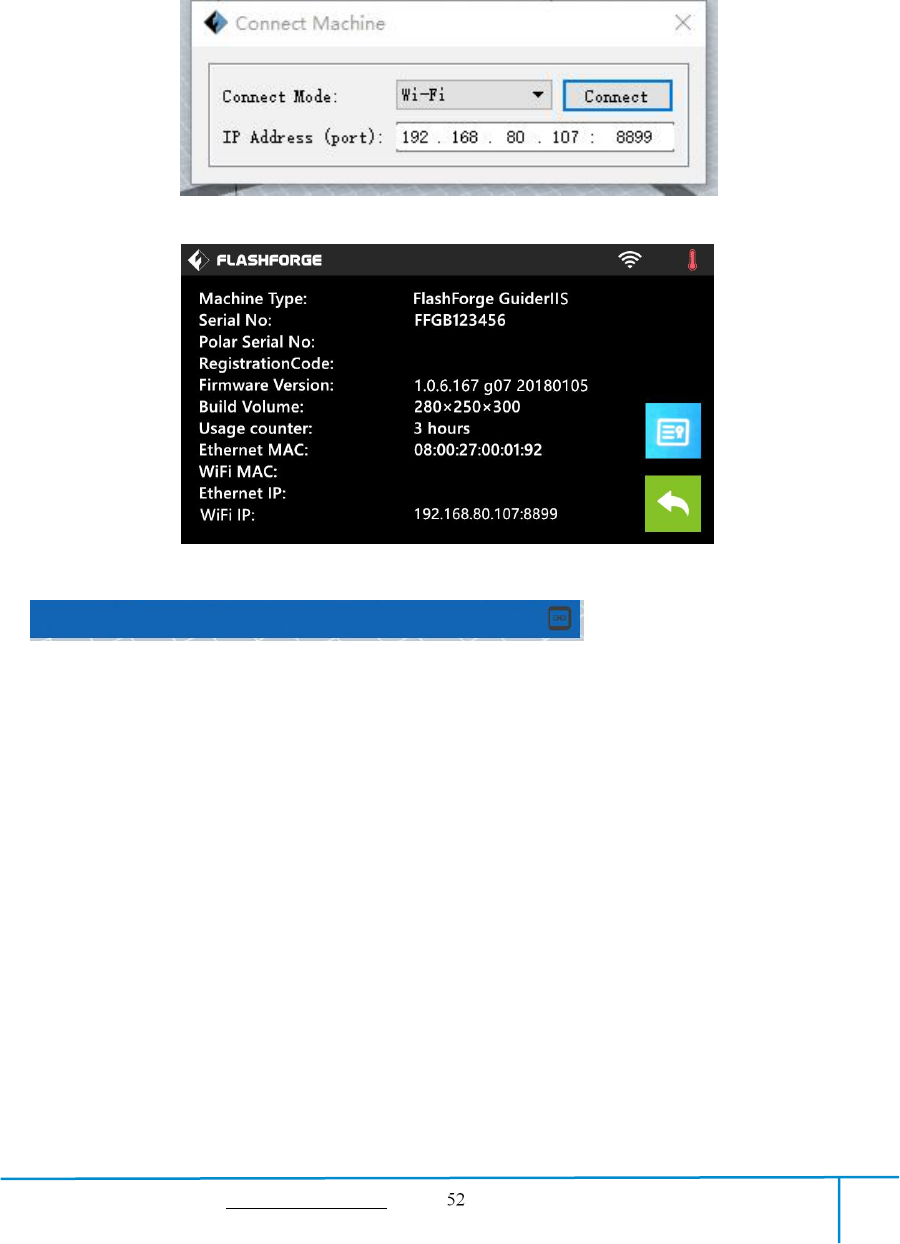
GuiderIIS User Guide | www.flashforge.com 400-699-1063
connect your computer and Guider IIS with the same WiFi signal.
b. Click [Print]-[Connect Machine] on FlashPrint. Then the following dialog
box pops up. You need to select “Wi-Fi” in Connect Mode. Enter into the IP Address
shown on the interface and then click [Connect].
If successfully connected, you will see the following mark on the right corner.
Disconnect GuiderIIS
Click [Print]--[Disconnect] to disconnect your PC and GuiderIIS.
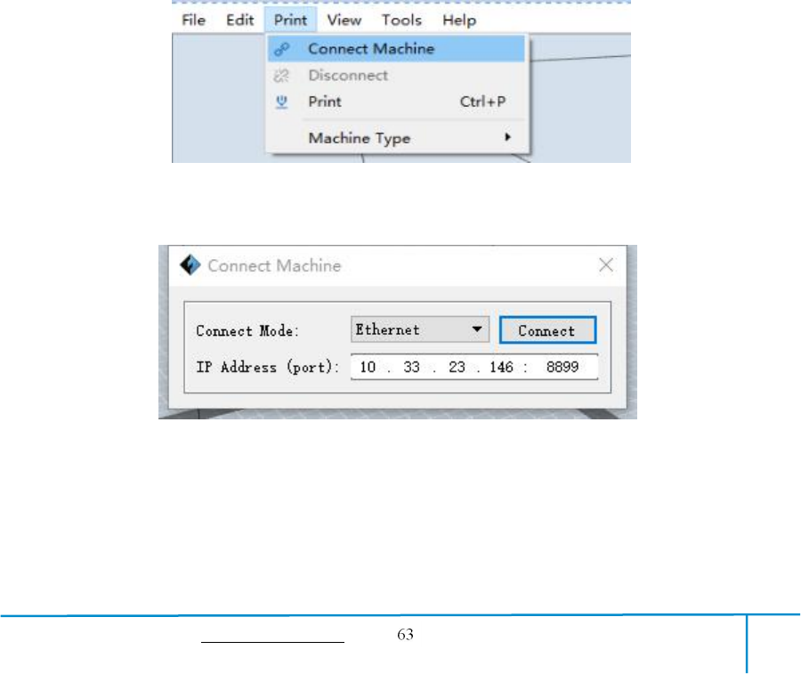
Method 3:Connect Via Ethernet
a. Connect your GuiderIIS with your PC via an Ethernet cable.
b. Turn on your GuiderIIS and start FlashPrint.
b. Click [Print]-[Connect Machine] on FlashPrint. Then the following dialog
box pops up. You need to select “Ethernet” in Connect Mode. Enter into the IP
Address shown on the interface and then click [Connect].
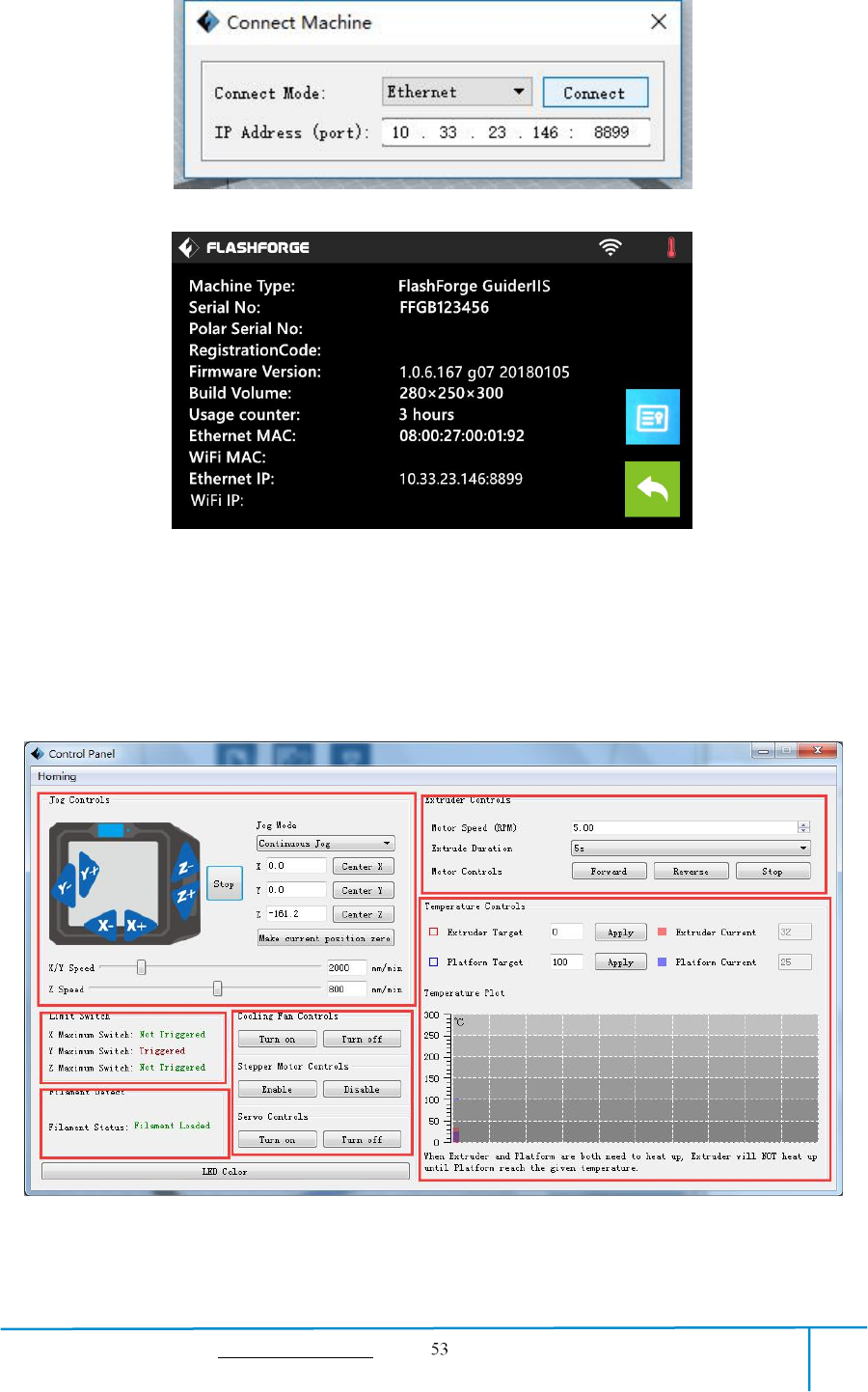

GuiderIIS User Guide | www.flashforge.com 400-699-1063
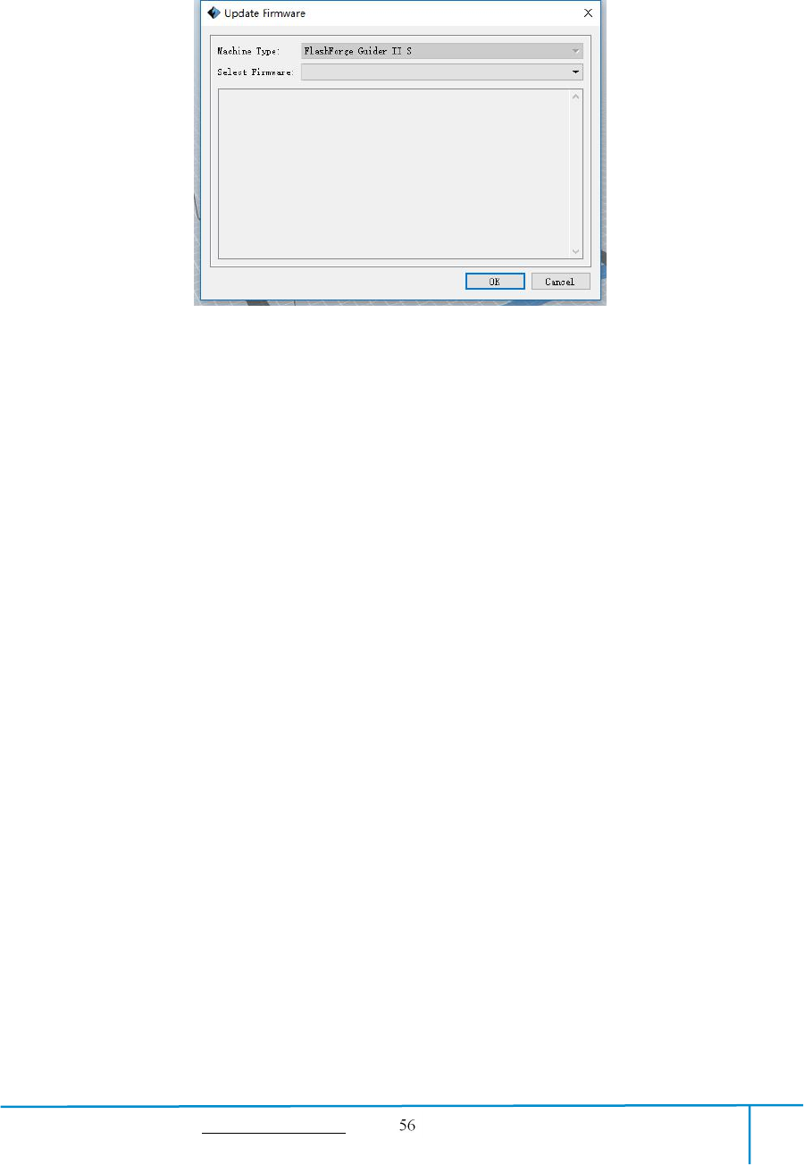
the distance extruder/ build plate move upon your single click).
b. Six blue arrow direction buttons: Control the move along X/Y/Z axis. X/Y axis
button control extruder move, Z axis button control build plate move. Click X-,
extruder will move leftward a specified distance; Click X+, extruder will move a
specified distance rightward. Click Y-, extruder will move forward a specified distance;
Click Y-, extruder will move backward a specified distance. Click Z-, build plate will
move upward a specified distance; Click Z-, build plate will move downward a
specified distance. (Specified distance refers to the move distance you set in Jog
Mode.
c. Stop: Click the [Stop] button to abort the current movement.
d. XYZ coordinate frame on the right side: Show the current position of
extruder/build plate.
e. Make Current Position Zero button: Set the current position of the
extruder/build plate as (0, 0, 0). (NOTE: X, Y, and Z boxes are for display purposes.
Changing the value in the boxes will not affect anything.
f. Center X/Y/Z button: Extruder and build platform will back to the zero (0, 0, 0)
you set last time.
g. X/Y Speed and Z Speed: Set the move speed of extruder/ build platform.
●Limit Switch: In order to protect your GuiderIIS, three limit switches are equipped
to control the maximum position, and the three limit switches corresponding to X/Y/Z
axis limit switch. It has two statuses:
a. Not Triggered: If the extruder/build plate don’t move to its maximum, X/Y/Z axis
limit switch is not triggered, and shows “Not Triggered”.
b. Triggered: If the extruder/build plate moves to its maximum, X/Y/Z axis limit
switch is triggered, and shows “Triggered”.
●Stepper Motor Controls: Allows users to control to stepper motor. Click [Enable],
and lock the motor so it does not allow any movement; click [Disable], and unlock the

GuiderIIS User Guide | www.flashforge.com 400-699-1063
motor to be controlled manually.
●LED Color: Allow users to change the LED color of GuiderIIS.
●Extruder Controls: You can set the value of “Motor Speed (RPM)”, which can
control the rotation speed of filament feeding wheel. The motor rotation time can be
controlled via setting the value of “Extruder Duration”. Generally we suggest the
users choose option of continuous time 60 seconds. The filament must be loaded in the
extruder before motor starts. Therefore, do not start rotation operation until the
extruder temperature reaches to the printing temperature of filament. For PLA
filament, the extruder temperature should reach 200℃, after reaching the extruder
temperature, click the [Forward]/[Reverse] rotation button to control filament load
and filament unload. Furthermore, if you want to stop filament load and unload, you
can click [Stop].
●Temperature Control: Input the temperature you want to get in the left frame, click
[Apply], the printer will automatically heat the corresponding part, the right side
shows the current actual temperature of corresponding part. After starting heating, the
below curve of temperature form will start to change, different color correspond
different parts’ temperatures
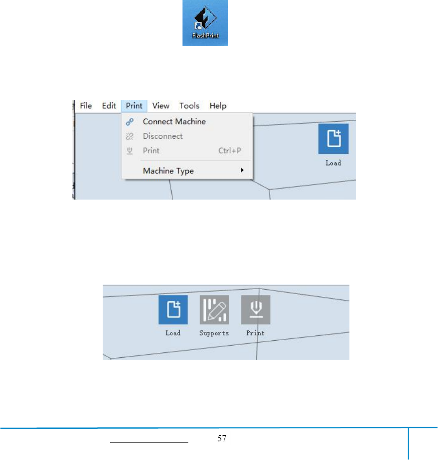
②Update Firmware
NOTE!Please update firmware under instructions of Flashforge engineer, Do not
recommend updating on your own.
Every time when you start FlashPrint, it will automatically detect and download the
up-to-date firmware. If any update is available, a dialog box will pop up for reminding
the users to update.
Step 1: Click [Tools]--[Update firmware]. It needs to cut off connection before
updating firmware. If software and printer are already in connection, it reminds you
cutting off the connection, and then choose [Yes] and go on to the next step.
GuiderIIS User Guide | www.flashforge.com 400-699-1063
Step 2: Choose corresponding printer type and firmware version and click [OK] in the
firmware updating box. After confirming the printer is in free state, the software will
automatically update the firmware
Step 3:Reboot you Guider Ⅱ and wait for 4-5 seconds, then you can see the update
process bar. When the update finishes, it will go back to the main interface.
Step 4:Tap [Tools]--[About] to check whether the updated version is right.
③On Board Preferences
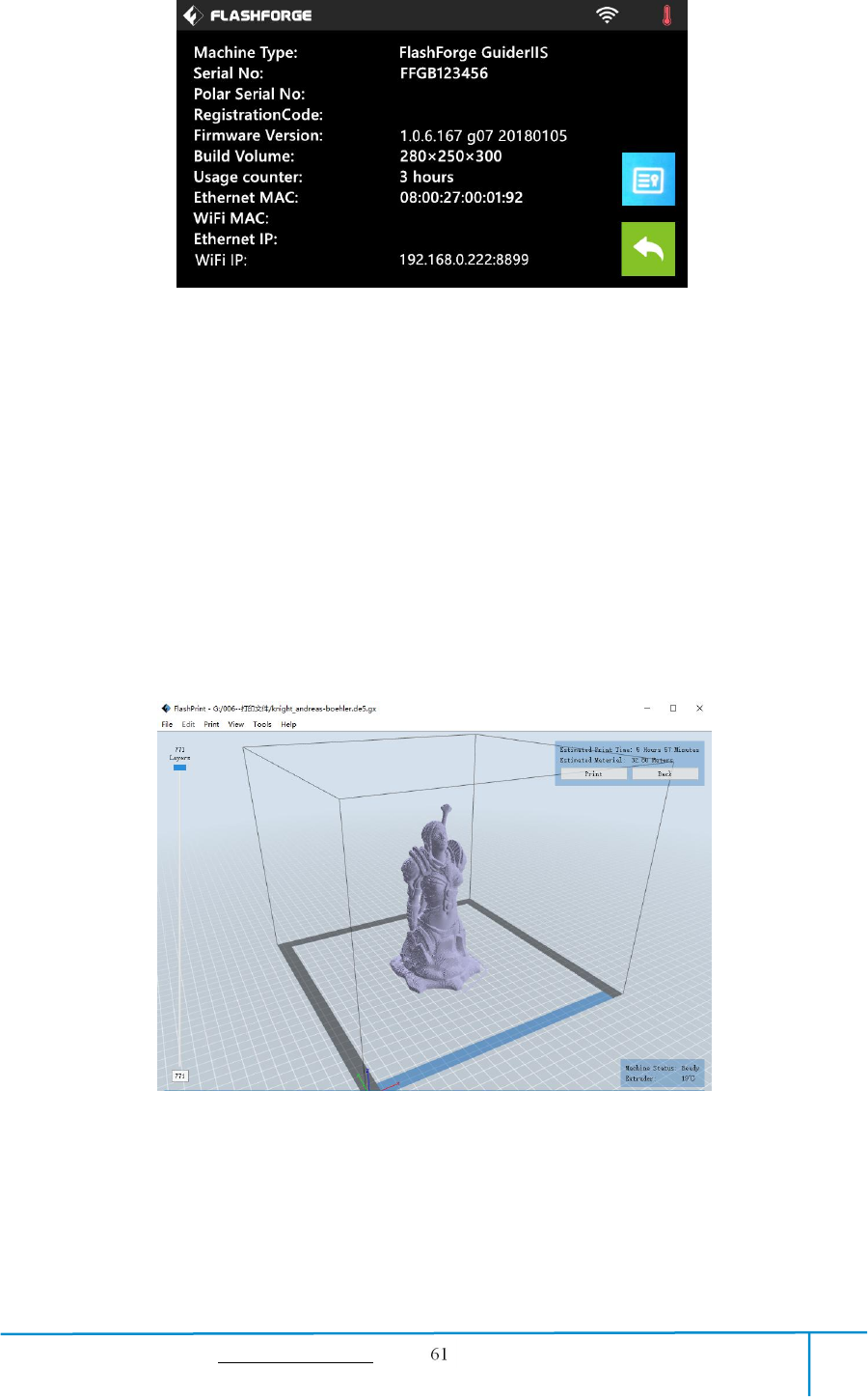
When the computer and printer are in connection, click [Tools]--[On Board
Preferences], you can check the printer name.
④Machine information
When the computer and printer are in connection state, click [Tools]--[Machine
information], you can check the machine type, machine name and firmware etc.
6.2.15 Help Menus
①First Run Wizard
②Help Contents:Click [Help]--[Help Contents], you can read the help contents.
③Check for Updates :Click [Help]--[Check for Update] to detect the available
updates online.
④About FlashPrint :Click [Help]--[About FlashPrint], the software information
box will pop up. The contents include the current software version and copyright
information.
GuiderIIS User Guide | www.flashforge.com 400-699-1063
Chapter 7: Basic Printing
This chapter will provide a step-by-step guide on turning a 3D model into a physical
reality. Before proceeding, it is recommended that you’d better go over prior chapters
on loading/unloading filament, leveling the build platform, and the functions and
capabilities of FlashPrint.
7.1 Generate a Gcode
(7-1)Double-click the icon of FlashPrint to start the software.
7-1
(7-2)Click [Print]--[Machine Type] to select FlashForge GuiderIIS
7-2
(7-3)Click the [Load] icon to load a .stl model file and the object will display on the
build area.
7-3
(7-4)Click [Edit]--[Surface to Platform] to make your model perfectly positioned
34
GuiderIIS User Guide | www.flashforge.com 400-699-1063
on the build area. Click [Back] and double-click the Move icon again, then click [On
the Platform] and [Center] to ensure the model be on the platform.
7-4
Note:If you’ve place your model in a right place, you can skip the step above.
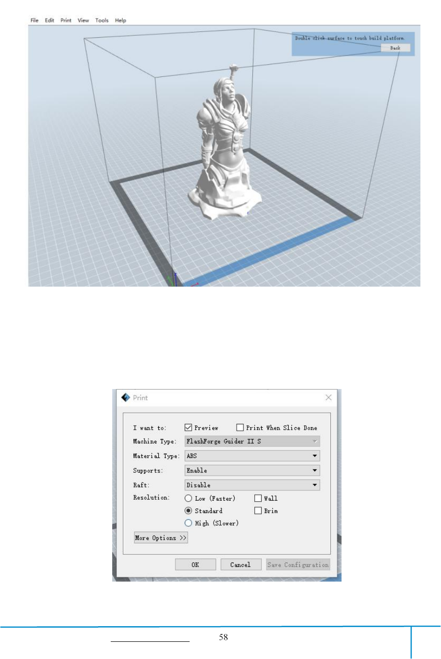
(7-5) Click the [Print] icon on the top, you should make some setups for your print
job.
Preview: If you check the [Preview] box, you can preview your model after slicing is
GuiderIIS User Guide | www.flashforge.com 400-699-1063
done.
Print When Slice Done: If you print via USB cable, you can check the box, while if
you print via USB, you should not check the box.
Machine Type: FlashForge Guider ⅡS
Supports: If you print a model with supports, you should click the inverted triangle
and select [Enable].
Raft: You are suggested to select [Enable].
Resolution: You are suggested to select [Standard]
More Options: You are suggested to keep them default.
Click [OK] to select the path to save the Gcode file. You can rename the file as you
like and save it as a .g or .gx file, click [Save] to generate a Gcode file.
Note: .gx files are available for preview while the .g files are not. They are displaying
as follows:
g. Files gx. Files
7-7
Next, we are going to print the model.
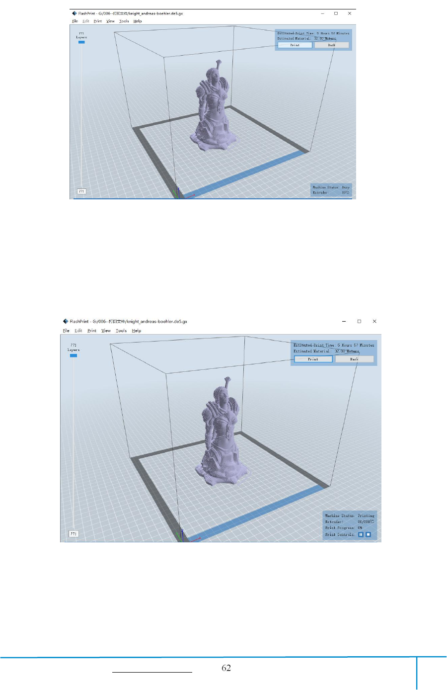
7.2 Print Methods
After generating the Gcode file, you can transfer it to your Guider ⅡS. You can
transfer the file through USB cable ,USB stick,WiFi , and Ethernet cable.
7.2.1 Print from Computer (USB cable connection)
①Connect your GuiderIIS with your PC via a USB cable.(Please refer to 6.2.13 )
②Turn on your Guider ⅡS, level the build plate and load the filament.
GuiderIIS User Guide | www.flashforge.com 400-699-1063
③Click [Print]and transfer your Gcode file to your Guider ⅡS. After completing
transference, the printer will heat up automatically. And when heating finishes, the
print will start to build the model.
④When your PC connects with FlashPrint successfully. The status box on the
bottom right displays the real-time nozzle temperature. After finishing preheating,
your Guider Ⅱ starts the print job directly.
7.2.2 Print from Computer (WiFi connection)
①Connect your GuiderⅡS with your PC via WiFi. (2 WiFi connection methods,
Please refer to 6.2.13 )
Enter into the IP Address shown on your GuiderIIS interface and then click
[Connect].
GuiderIIS User Guide | www.flashforge.com 400-699-1063
②Turn on your Guider ⅡS, level the build plate and load the filament.
③Click [Print]and transfer your Gcode file to your Guider ⅡS. After
completing transference, the printer will heat up automatically. And when heating
finishes, the printer will start to build the model.
If you want to print a Gcode from a local folder, you just need to load the file into
FlashPrint at the status of USB connection or WiFi connection or Ethernet connection,
then click the [Print] button on the top-right.
●Load the target Gcode file into FlashPrint.
7-9
●Click the [Print] button, the PC will transfer the Gcode file to the printer.
GuiderIIS User Guide | www.flashforge.com 400-699-1063
7-10
● After finishing transferring, the printer will heat up automatically. And when heating
finishes, the print will start to build the model.
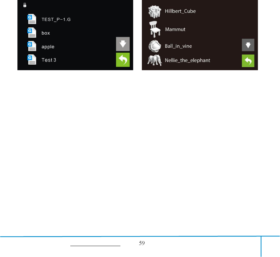
7.2.3 Print from USB Stick
①Insert your USB stick with target .g or .gx file to your Guider ⅡS .
②Turn on the GuiderIIS. Make sure the build plate has been leveled and the filament
7-11
GuiderIIS User Guide | www.flashforge.com 400-699-1063
is loaded.
③Tap [Print] and then tap the USB Stick icon in the middle. The file(s) will be
displayed on the screen. Select the file you want to print and tap [Print]. The file will
be transferred to the printer.
⑥And the printer will heat up the nozzle automatically and start to print after the
nozzle reaches the aimed temperature.,
Abort:To stop heating and printing. Once you tap [Abort], the process is irreversible.
Pause:To suspend the print job, you can tap it again to resume it. You can use this
function when you want to change the filament halfway.
7.2.4 Print from Computer (Ethernet Cable connection)
①Connect your GuiderIIS with your PC via an Ethernet cable.(Please refer to 6.2.13 )
Enter the IP Address shown on your GuiderIIS interface and then click [Connect].
GuiderIIS User Guide | www.flashforge.com 400-699-1063
②Turn on your Guider ⅡS, level the build plate and load the filament.
③Click [Print]and transfer your Gcode file to your Guider ⅡS. After completing
transference, the printer will heat up automatically. And when heating finishes, the
print will start to build the model.
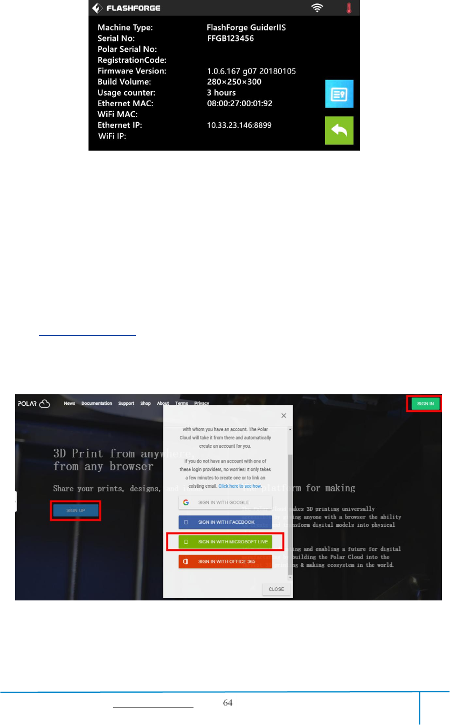
7.2.5 Print from Polar Cloud connection
1)Register a Polar Cloud account with your computer, on website:
https://polar3d.com/
Register your account using one of the four following options, take the third microsoft
live option as an example, create your new Polar Cloud account.
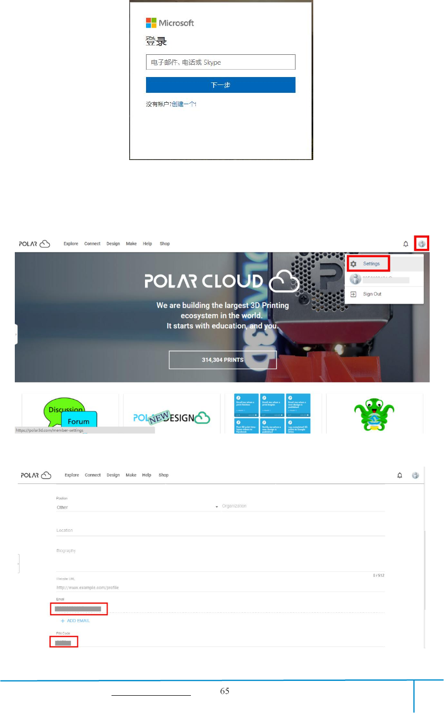
GuiderIIS User Guide | www.flashforge.com 400-699-1063
Connect the printer to internet with WiFi or Ethernet Cable;
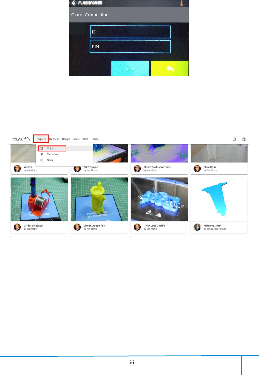
Tap [Tools]-[Settings]-[Polar Cloud connection] on printer’s touch screen;
Input your polar 3D cloud account’s Email address(as ID) and PIN Code, Tap[save] .
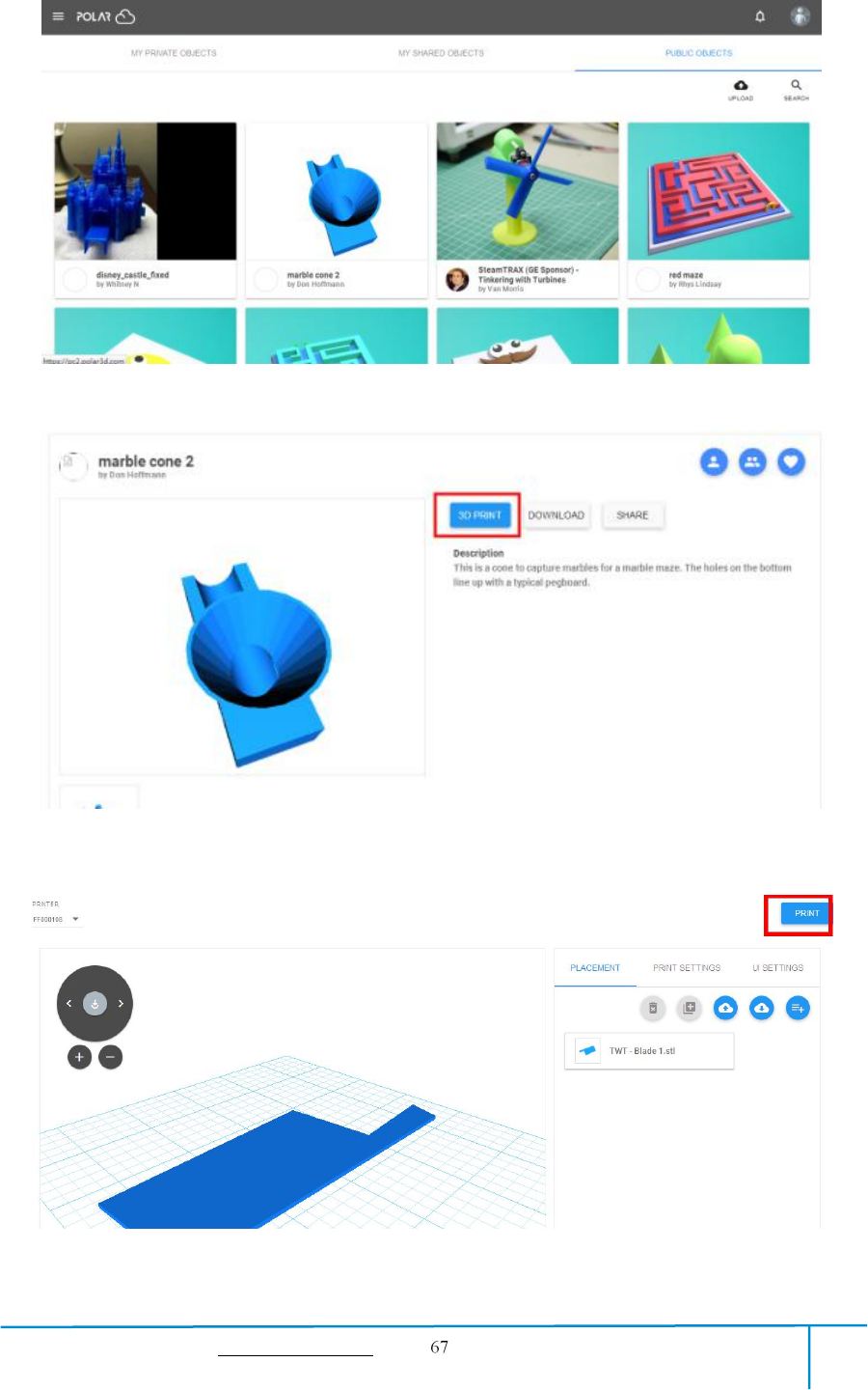
3)Enter the Polar Cloud homepage with your computer again. Tap [Explore] on the
left upper corner showed in the picture below, then Tap [Objects]
Enter the objects page, choose a model you are going to print.
GuiderIIS User Guide | www.flashforge.com 400-699-1063
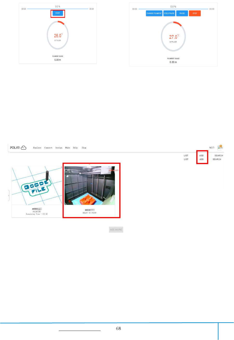
Tap【START】button,the printer starts downloading printing file automatically,after
downloading completed,you can interactively operate the printer on your computer,
including Change Filament, Pause, Stop etc.
4)More than one of the Flashforge printers can be added to a Polar 3D Cloud account,
Flashforge GuiderIIS/GuiderII, Finder, InventorIIS/InventorII, Adventurer3 printers
all support Polar 3D Cloud connection. After added to Cloud account and connected
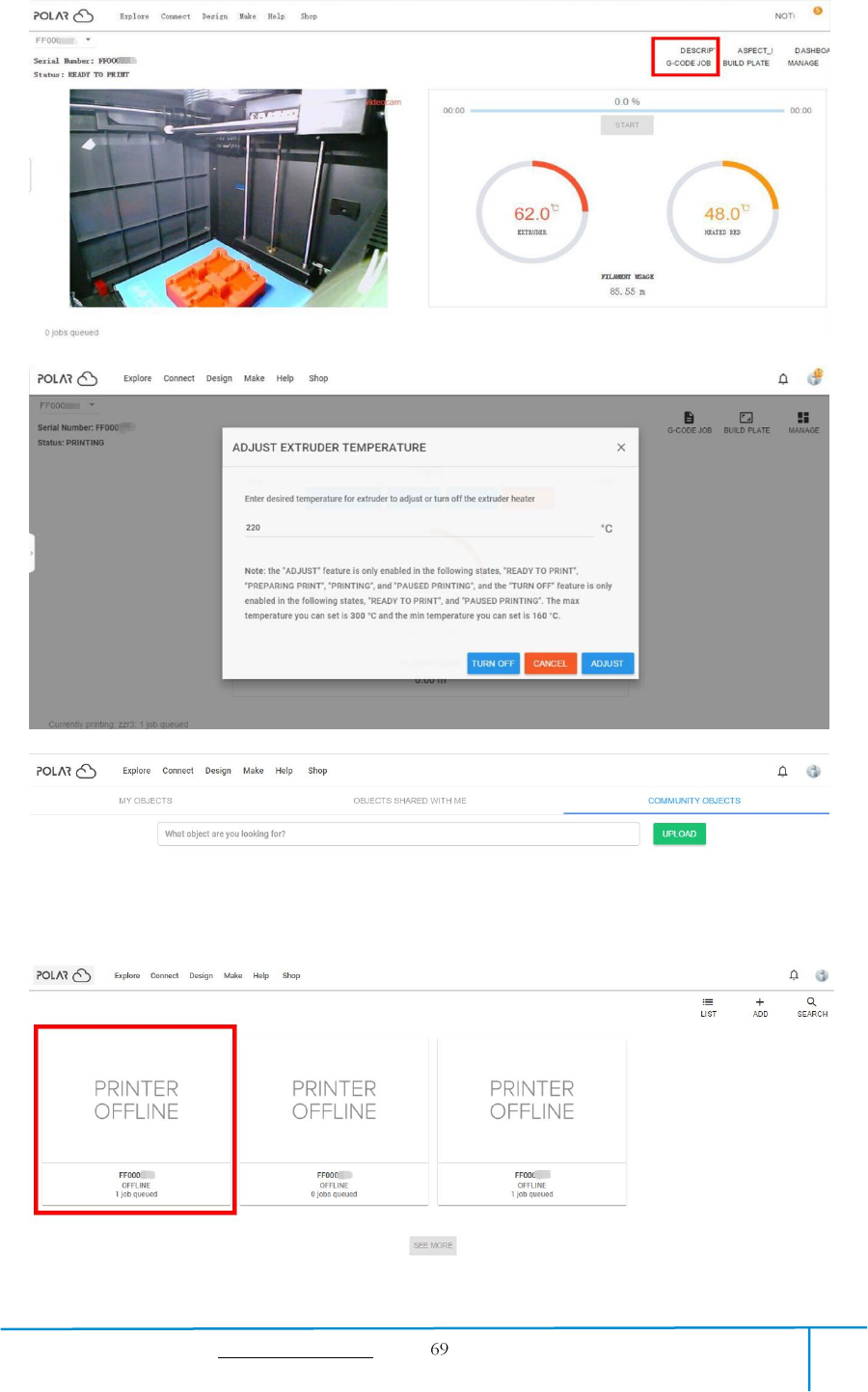
successfully, GuiderIIS printer’s camera can be used to monitor the real-time printing
status, as showed in the picture below:
5)By using Polar3D Cloud platform, you can create G-CODE printing job by
uploading your own sliced print files. Print files can be transferred to corresponding
printer and printing will be started automatically.
You can also adjust the extruder temperature, or explore other cloud functions.
GuiderIIS User Guide | www.flashforge.com 400-699-1063
6)Delete a printer from a polar cloud account.(If someone else wants to use the same
printer under another polar cloud account, please make sure you’v delete the printer
from your current-using polar cloud account, or others can not use the printer.)
Click the printer you want to delete.
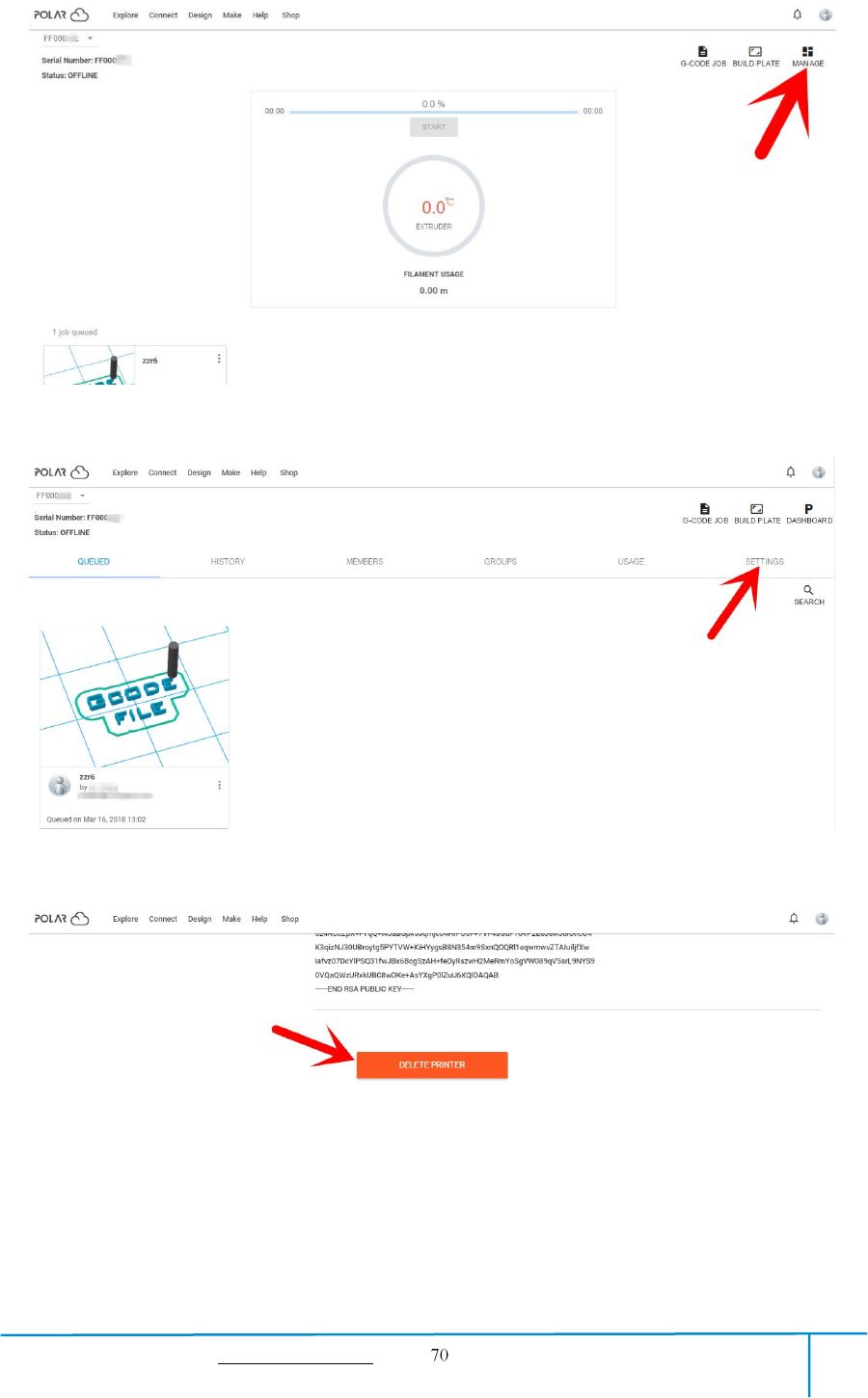
GuiderIIS User Guide | www.flashforge.com 400-699-1063
Click [MANAGE] button on the right upper position of this printer’s details webpage.
Then click [SETTINGS] button on the right upper position of the next webpage.
Finally, drag the next page to bottom down, click [DELETE PRINTER] button.
After you’v completed the above delete steps, this printer can now be used by others
under his own polar cloud account.
GuiderIIS User Guide | www.flashforge.com 400-699-1063
7.3 Camera
7.3.1 Connect from Polar Cloud
For detailed connection method,please refer to 7.2.5
After GuiderIIS printer has added to Polar Cloud account and connected
successfully(GuiderIIS printer and your computer should link to Internet by WiFi or
Ethernet cable, printer and computer do not need to connect the same WiFi signal),
Then GuiderIIS printer’s camera can be used to monitor the real-time printing status.
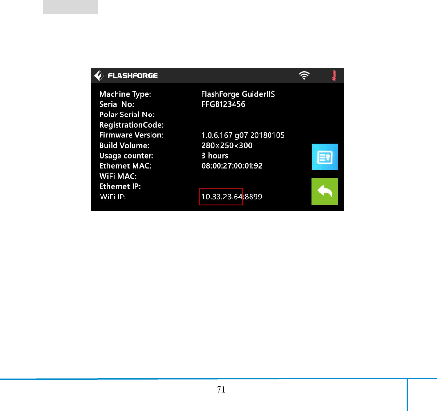
7.3.2 Direct Connect from computer
1) Connect your GuiderIIS printer and your computer to a same WIFI signal.
2) Install and start up Firefox browser(software) on your computer, type in the
following address as the format showed below, then you can monitor the real-time
printing status by the camera.
http://10.33.23.64:8080/?action=stream
(10.33.23.64 is your printer’s present IP address, this address must be edited
according to your printer IP address showed on printer touch screen.)

GuiderIIS User Guide | www.flashforge.com 400-699-1063
Chapter 8: Supports and Service
FlashForge team is on standby and ready to help you with any challenges you may
have with your Guider ⅡS. If the issues or questions are not covered in this User
Guide, you can seek for solutions on our official website or contact us via telephone.
There are solutions and instructions to common issues that can be found in our
knowledge base. Have a look first as most basic questions are answered there.
http://www.FlashForge.com
The FlashForge support team can be reached by e-mail or phone between the working
hours of 8:00 a.m. to 5:00 p.m. PST Monday through Saturday. In case you contact us
during off-duty time, your inquiry will be answered the following business day.
Note: Because of changing different filament the extruder maybe blockaded. It’s
not owing to quality issue, and outside the scope of 400 hours life. If users
encounter this problem, please contact our after-sale department and finish clean
work according to their instruction.
Tel:400-699-1063
QQ:2850862986 2850863000 2853382161
Email:support@ff3dp.com
ADD:No. 518, Xianyuan Road, Jinhua, Zhejiang
*When contacting support, please have your serial number ready. The
serial number is a bar code on the back of your GuiderIIS.”

GuiderIIS User Guide | www.flashforge.com 400-699-1063
Chapter 9:Basic Questions and Answers
Note! Do not disassemble the printer for maintenance on your own without
authorization, or it may cause unnecessary loss! Please contact Flashforge
after-sale engineers and use correct instruction and method to maintain.
9.1 Extruder shakes from left and right when printing.
Step 1. X-Axis motor cable has loose contact: Reconnect the X-Axis motor cable to
check, if problem remains, replace with new X-Axis motor cable.
Step 2. If Step1 not solving, X-Axis driver board has problem: Replace with new
X-Axis driver board.
9.2 “1025” extruder temperature showed on printer’s touch
screen when heating or printing.
Step 1. Extruder thermocouple has loose contact or has problem: Reconnect the
extruder thermocouple to check, if problem remains, replace with new extruder
thermocouple.
9.3 Extruder temperature does not go up when preheating or
loading filament.
Step 1. Heating pipe joint is disconnected with heating pipe: Reconnect these two parts
back.
Step 2. If Step1 not solving, heating pipe joint is disconnected from the exchange
board: Weld the heating pipe joint back if you are experienced in welding, or please
replace with new exchange board.
9.4 Extruder is moving to the right side without stop when
printing.
Step 1. X-Axis sensor wire has loose contact or has problem: Reconnect the X-Axis

GuiderIIS User Guide | www.flashforge.com 400-699-1063
sensor wire, if problem remains, replace with new X-Axis sensor wire.
Step 2. If Step1 not solving, trigger iron piece of the X-Axis sensor has dropped off or
has problem: Replace with new X-Axis sensor.
9.5 Print result is ellipse when we set to print perfect
roundness, and print result is rhombus when we set to print
rectangle.
Step 1. X-Axis is not vertical to Y-Axis: Check the verticality between X-Axis and
Y-Axis,adjust the X-Axis vertical to the Y-Axis.
9.6 Filament can not come out from extruder when printing
the first layer and extruder is rubbing the platform.
Step 1. Distance between extruder and platform is too small: Re-do the build plate
leveling according to Chapter 5.
9.7 Extruder is clogged, filament is jammed in the metal
throat tube or teflon tube.
Step 1. Clear and unclog the extruder.
Referring operating video: FLASHFORGE GuiderIIS Unclogging Extruder
https://www.youtube.com/watch?v=ePZgmtLxLZU&t=22s
9.8(1) Extruder motor rotates normally but filament comes
out from extruder not continuously(off and on).
(2)Extruder motor rotates normally but filament does not
come out from extruder, and new filament can not be loaded
into extruder or squeezed out.
1.Other brands filament is used in printer,inferior filament has impurities or bubbles
inside: Please use Flashforge filament and make sure filament be stored at clean and

GuiderIIS User Guide | www.flashforge.com 400-699-1063
dry conditions.
2. Filament diameter is too large,causing filament jammed inside teflon tube: Make
sure filament diameter is within 1.75±0.1mm. Replace with new filament if not fit.
3. Part of the filament is cracked inside the throat tube or teflon tube when plugging
out the filament after print finished or change filament:
Disassemble the extruder,clear and unclog the whole parts including teflon tube,throat
tube,extruder motor and nozzle.
4.False operation —directly insert the filament into extruder without cutting off the
melted tip part when reload in filament:Clear out the jammed filament fragment by
heating extruder and pushing the pin tool,replace the new filament,making sure
filament tip is smooth,not deformed or twisted.
5.Teflon tube is totally out of shape or the nozzle is totally jammed, these parts can not
be used any more: Replace with new teflon tube or new nozzle.
Referring operating video:
https://www.youtube.com/watch?v=sPYaoRWAp2o&t=28s
FlashForge-Guider IIS- Replacement of Nozzle and teflon Tube
9.9 Wave-like lines appear on the surface of models.
1. Apply some lubricate grease on the Z-Axis.
2. Z-Axis guide rods and Z-Axis bearings do not coordinate, or Z-Axis(motor axis)
and the copper sleeve do not coordinate: Check these parts, disassemble and
re-assemble these parts to check again, Replace corresponding problem parts with new
parts.
3.Z-Axis driver board has problem: Replace the Z-Axis driver board with the normal
X-Axis driver board or normal Y-Axis driver board (mind driver boards’ directions) , if
the problem is solved, replace the new Z-Axis driver board,if the problem is not solved,
replace the new Z-Axis motor.
9.10(1)One of the axis motor is not working or rotating.
1. Check to see whether something is blocked or other problems in the direction of
this moving axis: Clear out and fix these blocking problems.

GuiderIIS User Guide | www.flashforge.com 400-699-1063
2. Replace the malfunction motor’s driver board with normal axis motor’s driver
board, if the problem is solved, replace the new axis driver board, if the problem is not
solved, replace the new axis motor.
(2)Axis motor rotates only in one direction:
1. Refer to the steps in 9.10(1),but do not replace new axis motor.
2. Check the corresponding axis limit switch, plug out the joint of the limit switch.
9.11 Touch function on the touch screen does not work well.
Fastening screws behind the touch screen are too tightly screwed: Adjust the tightness
of these fastening screws, if not solving, replace a new touch screen.
9.12 Files sliced by Flashprint and transferred by USB stick
can not be identified by printer, or printer prompts: file is
not matched.
1.Restart the printer and re-plug out and re-plug in the USB stick.
2.Check to see whether the correct printer type GuiderIIS is selected in Flashprint.
3.Check to see whether the model size has exceeded limit printing size of GuiderIIS in
Flashprint.
4.USB stick has its own problems, copy the files to printer’s internal memory and start
print again, or use a new USB stick.
9.13 Print results shift along the direction of X-Axis.
1. X-Axis timing belt is loosened: Fasten the X-Axis timing belt.
2. X-Axis motor wire has loose contact or broken down: Reconnect the X-Axis motor
wire, if not solving, replace the new motor wire.
3. X-Axis driver board is broken down(step1 and step2 is gradually shifting, step3 and
step4 is whole-part shifting together with abnormal noise): Replace the new X-Axis
driver board.
4.Printing speed is too fast: Lower the printing speed.(Recommended basic printing

GuiderIIS User Guide | www.flashforge.com 400-699-1063
speed:40—60mm/s, travel speed:60—80mm/s)
9.14 When doing build plate leveling, touch screen prompts
“Please tighten knobs under the platform” when the knobs
have already been mostly tightened: Re-do the printer’s
extruder calibration and then do the build plate leveling
again.
Referring operating video: Extruder calibration
https://www.youtube.com/watch?v=VvjT3Y31IAw
FCC STATEMENT :
This device complies with Part 15 of the FCC Rules. Operation is subject to the following
two conditions:
(1) This device may not cause harmful interference, and (2) This device must accept any
interference received, including interference that may cause undesired operation.
Warning: Changes or modifications not expressly approved by the party responsible for
compliance could void the user's authority to operate the equipment.
NOTE: This equipment has been tested and found to comply with the limits for a Class B
digital device, pursuant to Part 15 of the FCC Rules. These limits are designed to provide
reasonable protection against harmful interference in a residential installation. This
equipment generates uses and can radiate radio frequency energy and, if not installed
and used in accordance with the instructions, may cause harmful interference to radio
communications. However, there is no guarantee that interference will not occur in a
particular installation. If this equipment does cause harmful interference to radio or
television reception, which can be determined by turning the equipment off and on, the
user is encouraged to try to correct the interference by one or more of the following
measures:
Reorient or relocate the receiving an tenna.
Increase the separation between the equipment and receiver.
Connect the equipment into an outlet on a circuit different from that to which the
receiver is connected.
Consult the dealer or an experienced radio/TV technician for help.
FCC Radiation Exposure Statement:
This equipment complies with FCC radiation exposure limits set forth for an uncontrolled
environment. This equipment should be installed and operated with minimum distance
20cm between the radiator & your body.