Zhejiang Flashforge 3D Technology INVENTOR2 InventorII (3D printer) User Manual Inventor2 Englishx
Zhejiang Flashforge 3D Technology CO., Ltd. InventorII (3D printer) Inventor2 Englishx
UserManual.wiki
>
Zhejiang Flashforge 3D Technology
>
INVENTOR2 User Manual
Manual
Navigation menu
Upload a User Manual
Namespaces
Wiki Guide
HTML
PDF
Info
Views
User Manual
Discussion / Help
Navigation

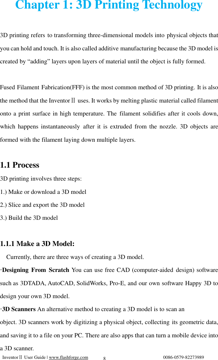
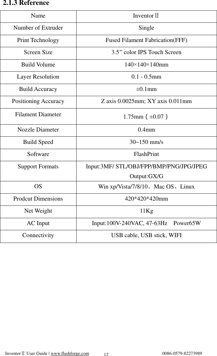
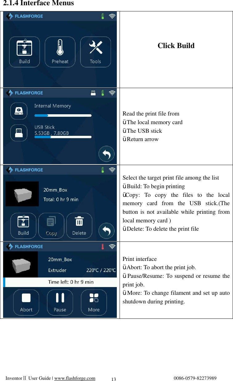
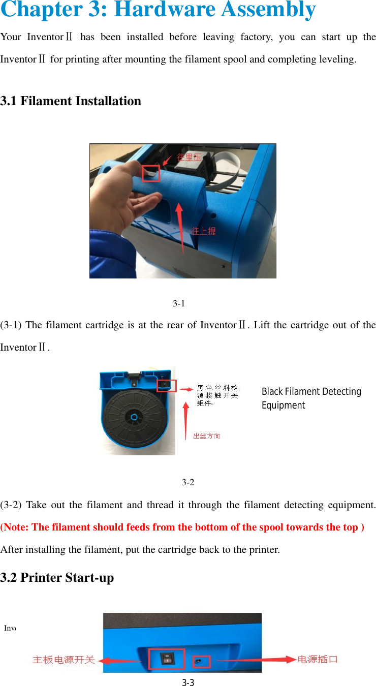
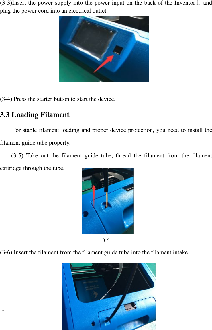
![InventorⅡ InventorⅡ User Guide | User Guide | www.flashforge.comlashforge.com 14 Tools in print interfaceŸFilament: To change filament during printing. (Note: You need to suspend the operation first)Ÿ FinishŸ Cancel: To end the tool orders and to the print interface. Tap the [Preheat] button to enter the preheat interface. Tap the [Start] button to heat up to the setting temperature.The default temperature is 220.℃Tap the temperature display bar to set the temperature. To set the preheat temperature. Tap [Yes] to save the setting while tap [No] to cancel the setting. Tools in print interfaceFilament: To change filament during printing. (Note: You need to suspend the operation first) Finish-Shut: To start auto shutdownCancel: To end the tool orders and to the print interface.Tap the [Preheat] button to enter the preheat interface. Tap the [Start] button to heat up to the setting temperature.The default temperature is 220.℃Tap the temperature display bar to set the temperature. To set the preheat temperature. Tap [Yes] to save the setting while tap [No] to cancel the setting. 0086-0579Tools in print interface Filament: To change filament during (Note: You need to suspend the operation Shut: To start auto shutdownCancel: To end the tool orders and to the print interface. Preheat Tap the [Preheat] button to enter the preheat interface. Tap the [Start] button to heat up to the setting temperature. The default temperature is 220.℃Tap the temperature display bar to set the To set the preheat temperature. Tap [Yes] to save the setting while tap [No] to cancel the setting. 0579-82273989 Filament: To change filament during (Note: You need to suspend the operation Shut: To start auto shutdown Cancel: To end the tool orders and return Preheat Tap the [Preheat] button to enter the preheat interface. Tap the [Start] button to heat up to The default temperature is 220.℃ Tap the temperature display bar to set the To set the preheat temperature. Tap [Yes] to save the setting while tap [No] Filament: To change filament during (Note: You need to suspend the operation return Tap the [Preheat] button to enter the preheat interface. Tap the [Start] button to heat up to Tap the temperature display bar to set the Tap [Yes] to save the setting while tap [No]](https://usermanual.wiki/Zhejiang-Flashforge-3D-Technology/INVENTOR2/User-Guide-3270333-Page-14.png)
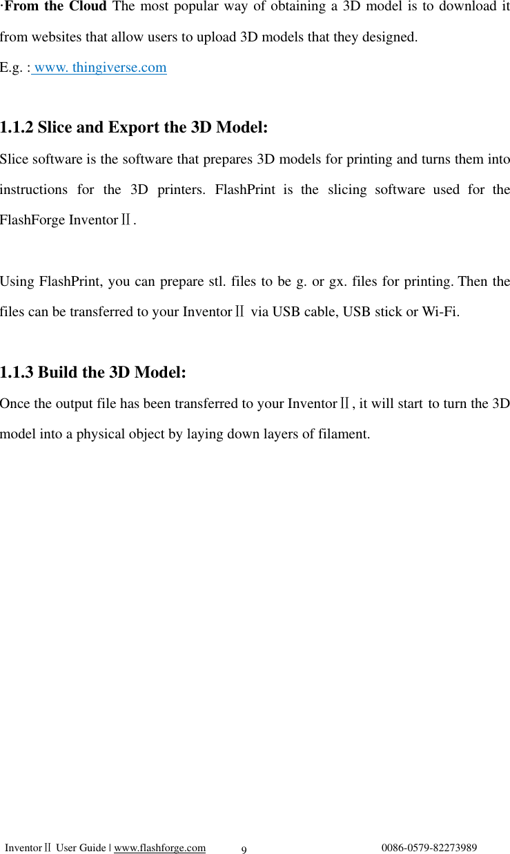
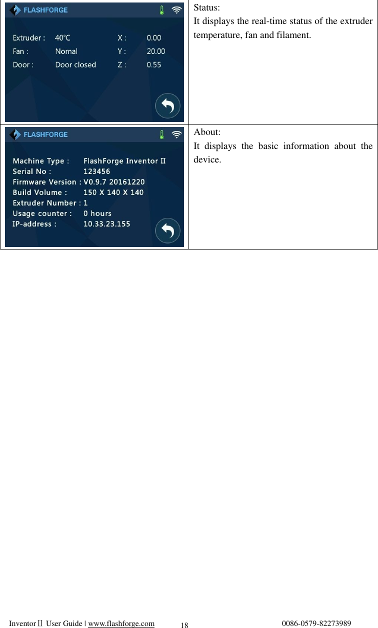
![InventorⅡ User Guide | www.flashforge.com 0086-0579-82273989 15 The picture displays the preheat interface. It shows the actual temperature and the target temperature. Tap the [Abort] button to abort the preheat job. Tools Tap [Tools] to enter tool options. Ÿ Filament: To load/unload the filament. Ÿ Level: To adjust the build plate. Ÿ Home: To make the X, Y and Z axes back to the zero point. Ÿ Manual: To manually adjust the positions of X, Y and Z axes. ŸSetting: To implement relevant function setups. ŸStatus: The check the real-time status of the printer. Ÿ About: Information about the printer. Ÿ Return arrow Manual adjustment Ÿ Y+: The extruder moves to the zero point, that is, the back of the machine Ÿ Y-: The extruder moves to the direction opposite to the Y+. Ÿ X+: The extruder moves to the zero points, that is, to the right direction ŸX-: The extruder moves to the direction opposite to the X+. Ÿ Z+: The build plate elevates. Ÿ Z-: The build plate descends. Ÿ Return arrow](https://usermanual.wiki/Zhejiang-Flashforge-3D-Technology/INVENTOR2/User-Guide-3270333-Page-15.png)
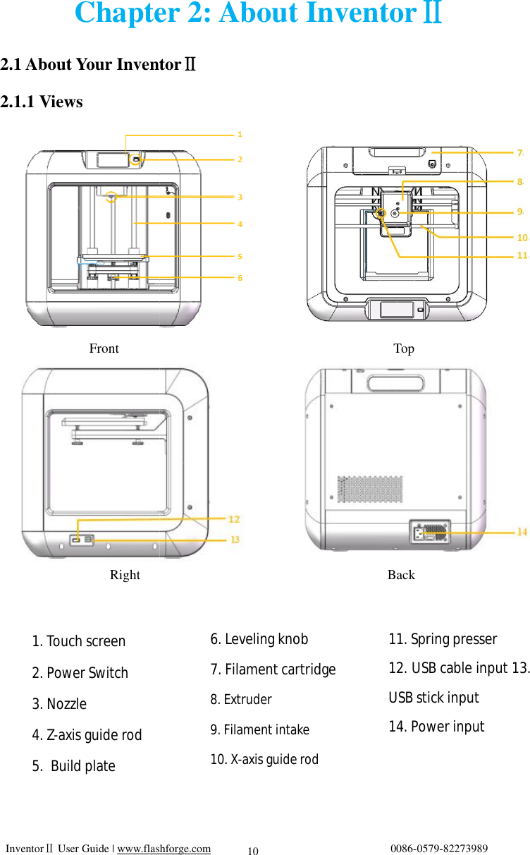
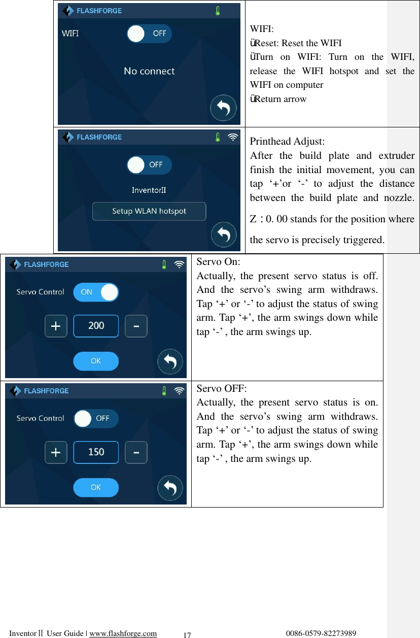
![InventorⅡ InventorⅡ User Guide | User Guide | www.flashforge.comlashforge.com 16 Tap [Setting] to enter the setting interfaceŸ Language: To set the display languageŸ TP Adjust: Adjust the touch screenŸ WIFI: To turn on/down the WIFIŸ Servo on: To turn on/down the servoŸPrinthead Adjust:distance between the extruder and the build plateŸFilament Check Off: To turn on/off the filament checkŸ Factory ResetŸ Return arrow TP AdjustTo tap the “+” on the touch screen to adjust the touch 0086-0579Tap [Setting] to enter the setting interfaceLanguage: To set the display languageTP Adjust: Adjust the touch screenWIFI: To turn on/down the WIFIServo on: To turn on/down the servoPrinthead Adjust:distance between the extruder and the build plate Filament Check Off: To turn on/off the filament check Factory Reset:Return arrow TP Adjust To tap the “+” on the touch screen to adjust the touch 0579-82273989 Tap [Setting] to enter the setting interfaceLanguage: To set the display languageTP Adjust: Adjust the touch screenWIFI: To turn on/down the WIFIServo on: To turn on/down the servoPrinthead Adjust: To adjust the initial distance between the extruder and the Filament Check Off: To turn on/off the :return to factory setting To tap the “+” on the touch screen to adjust the touch screen. Tap [Setting] to enter the setting interfaceLanguage: To set the display language TP Adjust: Adjust the touch screen WIFI: To turn on/down the WIFI Servo on: To turn on/down the servo To adjust the initial distance between the extruder and the Filament Check Off: To turn on/off the return to factory settingTo tap the “+” on the touch screen to Tap [Setting] to enter the setting interface To adjust the initial distance between the extruder and the Filament Check Off: To turn on/off the return to factory setting To tap the “+” on the touch screen to](https://usermanual.wiki/Zhejiang-Flashforge-3D-Technology/INVENTOR2/User-Guide-3270333-Page-16.png)
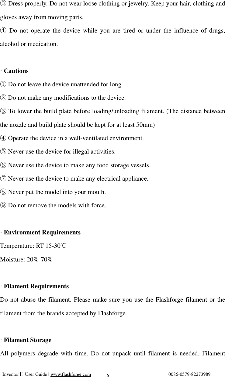
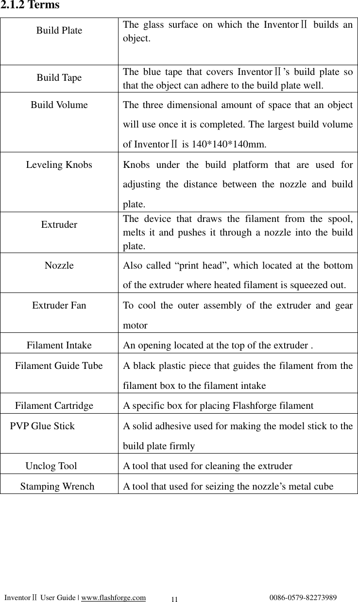
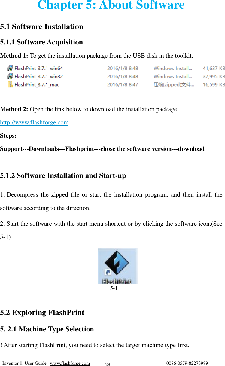
![InventorⅡ User Guide | www.flashforge.com 0086-0579-82273989 21 Next, we will load the Flashforge filament.(Note: Please lower the build plate to increase the distance between the nozzle and build plate to 50mm at least for avoiding nozzle jam.) (3-7) Tap [Tool]. 3-8 (3-8) Tap [Filament]--[Load] 3-9 (3-9)After the extruder’s temperature reaches 220, the printer will sound a beep to℃ 3-7](https://usermanual.wiki/Zhejiang-Flashforge-3D-Technology/INVENTOR2/User-Guide-3270333-Page-21.png)
![InventorⅡ User Guide | www.flashforge.com 0086-0579-82273989 22 prompt you to load the filament into the extruder. 3-10 (3-10)Insert the filament into the extruder at an upright angle. Then the filament will be drawn through the extruder. Do not tap [Cancel] until the filament load the extruder steadily. 3.4 Unloading Filament 3-11 (3-11) Tap [Tool]-[Unload] and the extruder starts heating up.](https://usermanual.wiki/Zhejiang-Flashforge-3D-Technology/INVENTOR2/User-Guide-3270333-Page-22.png)

![InventorⅡ User Guide | www.flashforge.com 0086-0579-82273989 24 Chapter 4: Build Plate Leveling InventorⅡ creatively adopts three-point intelligent leveling system, which will give clear and comprehensive feedback to users. There are three spring-loaded knobs under the build platform. The distance between the plate and nozzle increases while tightening the knobs. On the contrary, the distance reduces. (4-1) Tap [Tools] - [Level] on your InventorⅡ touch screen. Please wait while the extruder and platform finish initial movements. After that, operate according to the guide on the touch screen. 4-1 (4-2) After tapping [Yes], the extruder starts to move towards the first point and the plate moves up and down to verify the distance between nozzle and plate.](https://usermanual.wiki/Zhejiang-Flashforge-3D-Technology/INVENTOR2/User-Guide-3270333-Page-24.png)
![InventorⅡ User Guide | www.flashforge.com 0086-0579-82273989 25 4-2 (4-3) When it shows that the distance is too big, please unscrew corresponding nut under platform clockwise until hearing a steady beep and the [Verify] button appears. 5-4 4-3 (4-4) If the distance is appropriate, tap [OK] to second point leveling. If still not, please follow the prompts to adjust again till you see [OK] button. 4-5 (4-5) Repeat steps 2 through 4 above to complete second and third points leveling and then Tap [Finish] to exit.](https://usermanual.wiki/Zhejiang-Flashforge-3D-Technology/INVENTOR2/User-Guide-3270333-Page-25.png)
![InventorⅡ User Guide | www.flashforge.com 0086-0579-82273989 26 Leveling Emergency Plan: Some leveling spare parts may be damaged after being used for a period of time. Now users could adopt the emergency plan for leveling. (1)Insert the USB stick to the USB port. (2)Tighten each of the three knobs underneath the build platform until they go no further (3)Tap [Build] on the touch screen, tap the USB icon and then select Leveling.g file. (4)Tap [Build], then the build plate and the extruder start moving. (5)After they stop moving, you can adjust the distance between the build plate and the nozzle manually. Move the extruder to the position right over the front-left knob, and adjust the knob individually. Use a A4 paper to check the distance. As you adjust the knob, make sure the paper just slides between the nozzle and build plate. There will be somewhat friction on the paper but still can easily pass the paper between the plate and the nozzle without tearing or damaging the paper. (6)Then move to the positions right over the right-front and rear knobs successively, and then adjust the distance according to the descriptions above. (7)Then move to the center of the build plate for a check. Confirm that the paper slides between the nozzle and build with a moderate amount friction.](https://usermanual.wiki/Zhejiang-Flashforge-3D-Technology/INVENTOR2/User-Guide-3270333-Page-26.png)

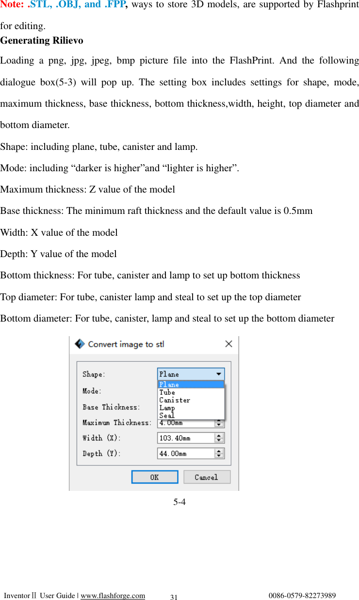
![InventorⅡ User Guide | www.flashforge.com 0086-0579-82273989 29 When you start FlashPrint, a dialog box will pop up. Just select Flashforge InventorⅡ in the machine type list and click [OK]. You can also change the machine type via clicking [Print]--[Machine type]. See graphic 5-2: 5-2 5.2.2 Software Introduction 5-3](https://usermanual.wiki/Zhejiang-Flashforge-3D-Technology/INVENTOR2/User-Guide-3270333-Page-29.png)
![InventorⅡ User Guide | www.flashforge.com 0086-0579-82273989 30 Load one or multiple files. Enter the support edit mode Print it directly with your InventorⅡ or export to your USB Stick View FlashPrint home screen from one of six viewing angles Move model around on xy-plane; shift+click to move along z axis Turn and rotate your model Scale the size of your object Cut model into several parts 5.2.3 Loading You can load a model file or Gcode file into your Flashprint by the following six methods: Method 1: Click the Load icon on the main interface. Then select the object file. Method 2: Select the file for loading and drag the file to the main interface of the software. Method 3: Click [File]--[Load File]. Then select the object file for loading. Method 4: Click [File]--[Examples] to load the example files Method 5: Click [File]--[Recent Files] to load the files opened recently. Method 6: Select and drag the target file to the icon of Flashprint.](https://usermanual.wiki/Zhejiang-Flashforge-3D-Technology/INVENTOR2/User-Guide-3270333-Page-30.png)
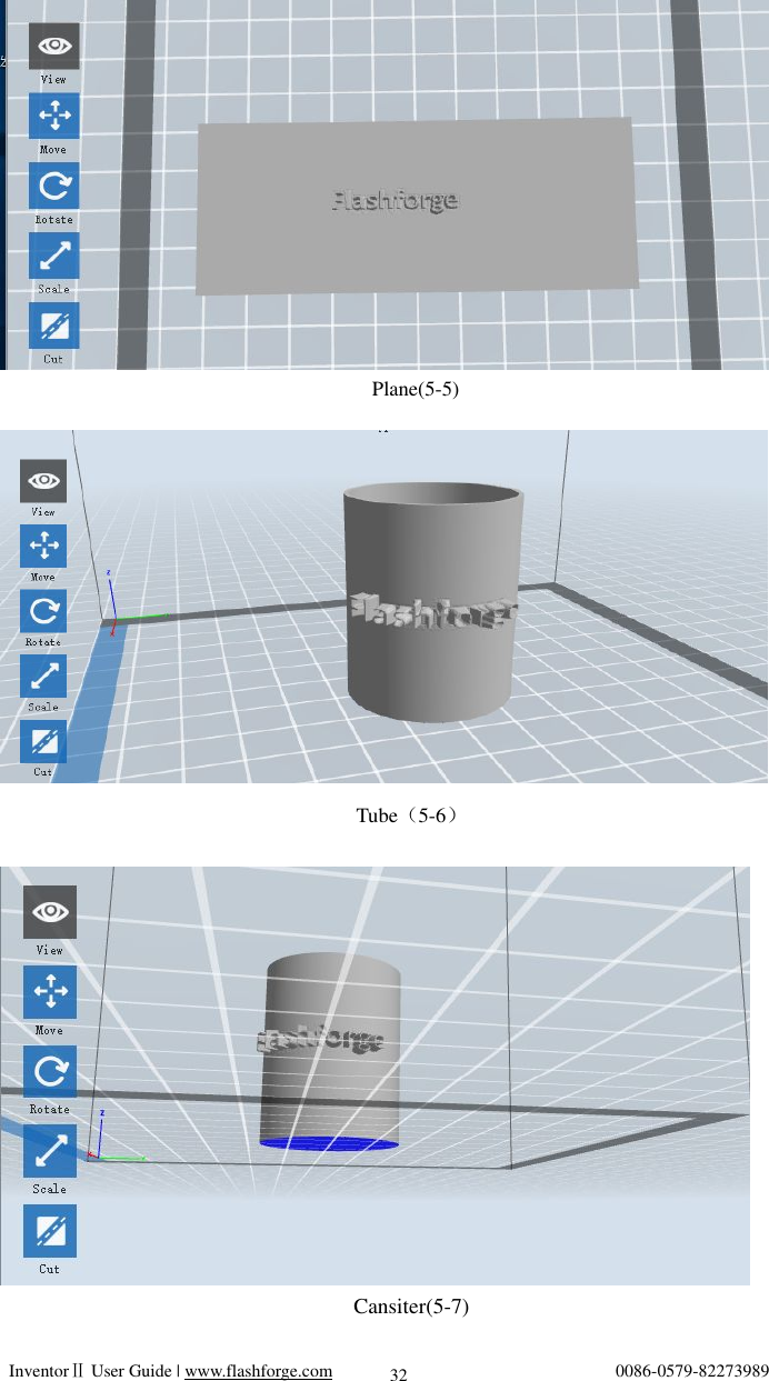
![InventorⅡ User Guide | www.flashforge.com 0086-0579-82273989 33 Lamp(5-8) Seal(5-9) 5.2.4 Views Changing views① Change model views by moving, rotating, scaling. ● Drag Click the [View] icon and then you can move the object by the following three methods: Method 1: Hold down the left mouse button and drag. Method 2: Hold down the middle mouse button and drag.](https://usermanual.wiki/Zhejiang-Flashforge-3D-Technology/INVENTOR2/User-Guide-3270333-Page-33.png)
![InventorⅡ User Guide | www.flashforge.com 0086-0579-82273989 34 Method 3: Hold down the Shift key, hold down the right mouse button and drag. ● Rotate Click the [View] icon and then you can rotate the object by the following two methods: Method 1. Hold down the right mouse button and drag. Method 2. Hold down the Shift key, hold down the left mouse button and drag. ● Scale Rotate the mouse wheel to enlarge or shrink the build plate. ②Set View Allows users to view the object on the build plate. Six views are under the view menu, that is, home view, bottom view, top view, front view, back view, left view and right view. Method 1: Click the the [View] button, there are six views in the drop- down list Method 2: Click the the [Look] icon on the left, click it again and a submenu will appear with six views for selecting. ③Reset View Allow users to reset views by the following two methods: Method 1: Click the [View] menu and select [Home View] Method 2: Click the [View] button on the left, click it again and you will see the viewing options, you can click [Reset]. ④Show Model Outline Click [View]--[Show Model Outline], it will highlight the yellow border of the object](https://usermanual.wiki/Zhejiang-Flashforge-3D-Technology/INVENTOR2/User-Guide-3270333-Page-34.png)
![InventorⅡ User Guide | www.flashforge.com 0086-0579-82273989 35 ⑤Show Steep Overhang Click [View]--[Show Steep Overhang]. When the intersection angle between the model surface and horizontal line is within the overhang threshold value, the surface has steep overhang and it becomes red in the software. Overhang threshold value could be set as needed. The default value is 45 degree. 5.2.5 Move Select the object and move the object by the following two methods: Method 1: Click the [Move] icon on the left, hold down the left mouse button and drag to adjust the location of the model in XY direction. Hold down the Shift key, hold down the left mouse button and drag to adjust the location of the model in Z direction. The distance and the direction of the movement shall be displayed. Method 2: Click the [Move] button on the left and then enter the distance value. Click [Reset] to reset distance values. Note: Users shall click [Center] and [On Platform] after the location adjustment to ensure the model(s) be within the build area and on the build platform. If a specified position is needed, only to click [On Platform]. 5.2.6 Rotate Select the target object and rotate the object by the following two methods: Method 1: Click the [Rotate] icon on the left and three mutually perpendicular rings appear around the object Click one ring and rotate on the present axis, you will see the rotation angle and direction in the center of circle. In this way, you could make the model rotate on X/Y/Z axis. Method 2: Click the [Rotate] icon on the left, and then enter into rotating angel values in X/Y/Z axes positioning. Click [Reset] to reset rotating angel values.](https://usermanual.wiki/Zhejiang-Flashforge-3D-Technology/INVENTOR2/User-Guide-3270333-Page-35.png)
![InventorⅡ User Guide | www.flashforge.com 0086-0579-82273989 36 5.2.7 Scale Select the target object and scale the object by the following two methods: Method 1: Click the [Scale] icon on the left, hold down the left mouse button and scale the model. The corresponding values will display near the object. Method 2: Click the [Scale] icon on the left and then enter into scale values in X/Y/Z axes positioning. Click the [Maximum] button to get largest size possible for building. Click [Reset] to reset the size of model. Note: If the [Uniform Scaling] radio button is clicked, it will scale the model in equal proportion when changing value in any positioning of the model. Otherwise it will only change the value of the corresponding positioning. 5.2.8 Cut Left-click on the model to select it and double-click on the Cut icon to set the cut plane. The direction and position are available for setting. Draw with Mouse① X Plane②](https://usermanual.wiki/Zhejiang-Flashforge-3D-Technology/INVENTOR2/User-Guide-3270333-Page-36.png)
![InventorⅡ User Guide | www.flashforge.com 0086-0579-82273989 37 Y③ Plane Z Plane④ 5.2.9 Supports After loading the model, click [Edit]--[Supports] or click the Supports icon directly, then you will enter the support edit mode(as shown in the picture below). Click [Back] to exit when you finish editing. 5-10 Support Options①](https://usermanual.wiki/Zhejiang-Flashforge-3D-Technology/INVENTOR2/User-Guide-3270333-Page-37.png)
![InventorⅡ User Guide | www.flashforge.com 0086-0579-82273989 38 Click the Support Options, an option box will appear, supports options include “treelike”and “linear”, when choose “treelike”, click [OK], then it will generate treelike structure; when choose “linear”, click [OK], then it will generate linear structure; if it is a model with supports, when you choose one of the supports options, software will judge whether existing supports need to be deleted or not on the basis of the type of existing support, and will pop up the corresponding prompt to let you make the choice. ②Auto Supports Click the [Auto Supports] button, the software will judge the position where supports are needed and generate corresponding treelike or linear supports. If it is a model with supports, the existing supports will be deleted and new supports will be generated. ③Add Supports Supports will be added once clicking the [Add] button. Move the cursor to the position where supports needed, left-click to choose the starting point of supports, hold down the left mouse button and drag the mouse the supports preview will show up(if support surface doesn’t need support or the support column angle is too large, will highlight the support review ). Loosen the left mouse button, if support column doesn’t meet with model, then support will be generated on origin and terminal 5-11](https://usermanual.wiki/Zhejiang-Flashforge-3D-Technology/INVENTOR2/User-Guide-3270333-Page-38.png)
![InventorⅡ User Guide | www.flashforge.com 0086-0579-82273989 39 point(the highlighted preview support won’t generate support structure ) ④ Clear Supports Click [Clear Supports], all supports will be deleted. The operation can be repealed via clicking [Undo] or pressing the shortcut key Ctrl+Z. ⑤Delete Supports Supports will be deleted once clicking the [Delete] button. Move the cursor to the supports needed deleting, current supports and its subnode support will be highlighted, click the left mouse button to delete these highlighted support. 5.2.10 Print Preview:① Choose to enter preview interface or not Print when slice done: ②Print or not when slice done 5-12](https://usermanual.wiki/Zhejiang-Flashforge-3D-Technology/INVENTOR2/User-Guide-3270333-Page-39.png)
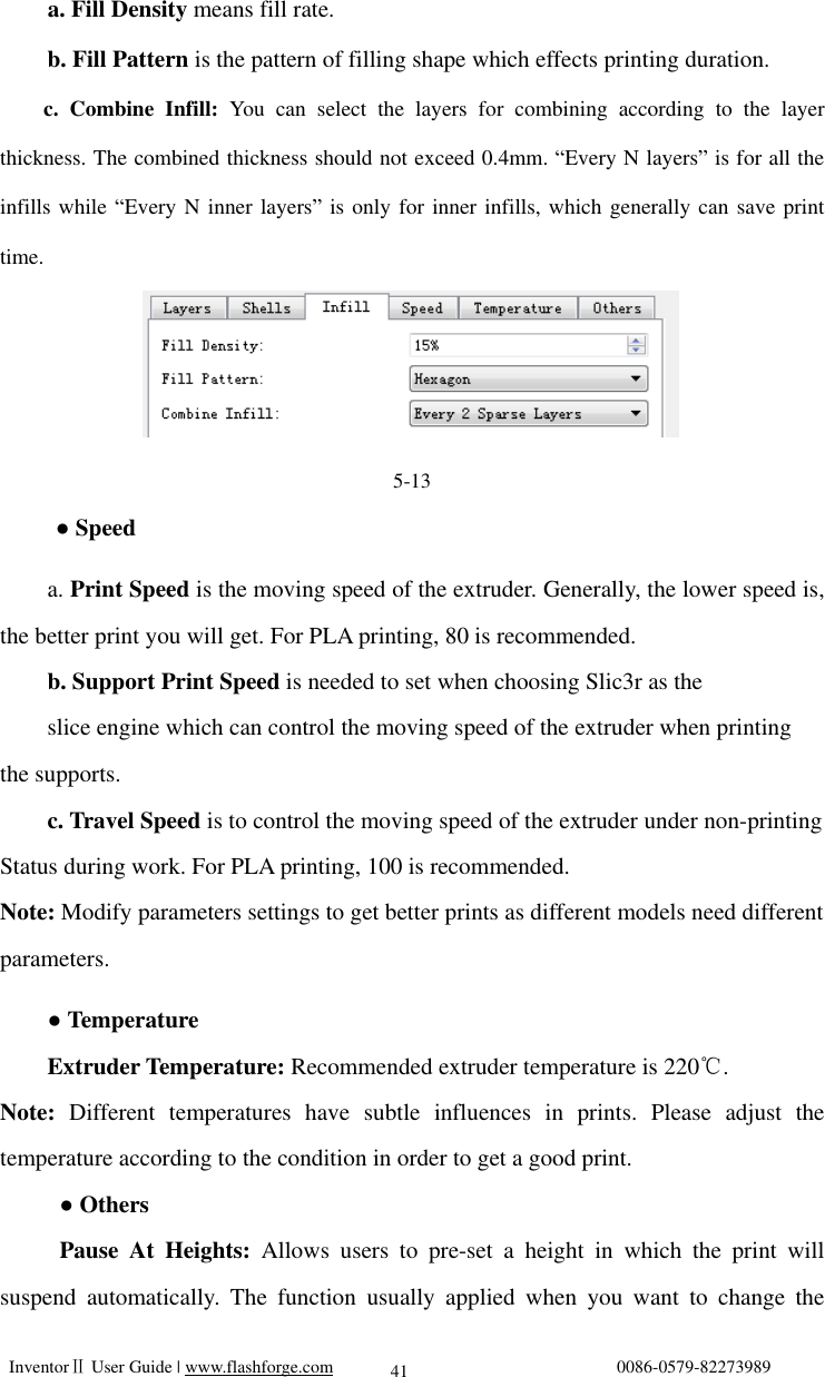
![InventorⅡ User Guide | www.flashforge.com 0086-0579-82273989 40 Material type:③ Choose according to the type of model Supports:④ When print suspended structure models, support is necessary. Click [supports] to create support part for the printing. Raft:⑤ This function will help the model to stick well on the platform. Wall:⑥ During dual color printing, this function will help to clear the leaking filament of another extruder. Vase Mode: ⑦No capping for the model Resolution⑧:You have three resolution solution(with default setting)to choose from, high resolution is corresponding with slow printing speed, opposite for the low resolution. For PLA printing, an extra solution “Hyper” is available. More options:⑨ Click [More options] to set for layer, shell, infill, speed and temperature. Different resolution solution is corresponding to different defaults, click [Restore Defaults] to back to default setting. ●Layer a. Layer: Layer thickness of the printing model. With a small value, the surface of the model will be more smooth. b. First Layer Height: This is the first layer of the model, which will affect the sticking performance between the model and platform. Maximize is 0.4mm, usually the default is ok. c. Shell: Contains the outside shell value, capping layer value (under vase pattern, top solid layer setting is invalid.) ● Primeter Shells: Maximize is 10 a. Top Solid Layer: Maximize is 10, minimum is 1. b. Bottom Solid Layer: Maximize is 10, minimum is 1. ● Infill](https://usermanual.wiki/Zhejiang-Flashforge-3D-Technology/INVENTOR2/User-Guide-3270333-Page-40.png)
![InventorⅡ User Guide | www.flashforge.com 0086-0579-82273989 42 filament at a certain point. (5-13) Click[Edit], then you can add or remove a height. 5.2.11 File Menus ①New Project Click [File]--[New Project] can build a blank project. If there is an unsaved modification on previous project, then it will inform you whether the modification needs to be saved or not. Click [Yes] will save the modification, click [No] will abandon it. If click [Cancel] or close tool tip, then will cancel the new project. ②Saving After finishing the model edit and adjustment, there are two ways below to save all models in the scene. Method 1: Click [File]--[Save Project] in the menu bar to save the file as a project file with the “.fpp”suffix, all models in the scene (include support) are independent . After reloading the files, extruder configuration information and model position will be the same as the configuration during saving. 5-15 5-14](https://usermanual.wiki/Zhejiang-Flashforge-3D-Technology/INVENTOR2/User-Guide-3270333-Page-42.png)
![InventorⅡ User Guide | www.flashforge.com 0086-0579-82273989 43 Method 2: Click on [File]--[Save as...] to save the model as project file .fpp or .stl and .obj. For .stl and .boj, models are integrated as one(include support part). If load it again, only the position of the model was saved, not included the printing parameters. ③Preferences Click [File]--[Preferences], you can choose language and if needs detecting update when start ● Language: The software supports six languages, namely, Chinese(simplified Chinese and traditional Chinese), English, French, Korean, Japanese and Russian. ● Printing Window Type: Including Base Mode and Expert Mode ● Check for Update after start up: It is used to preset if it is necessary to activate the online automatic update function, if choose yes, every time when you open software, it can online detect if it is a new version software, once new version found, it will reminds users to download and install new version firmware. 5.2.12 Edit Menus ①Undo Allows users to undo the recent edits by the following two methods: Method 1: Click [Edit]--[Undo]. 5-16](https://usermanual.wiki/Zhejiang-Flashforge-3D-Technology/INVENTOR2/User-Guide-3270333-Page-43.png)
![InventorⅡ User Guide | www.flashforge.com 0086-0579-82273989 44 Method 2: Press the shortcut Ctrl+Z. ② Redo Allows users to redo the most recent edit you have undone to your model file by the following two methods Method 1: Click [Edit]--[Redo] Method 2: Press the shortcut Ctrl+Y. ③Empty Undo-stack To clean up the recorded operating steps so as to release the memory. ④Select All By the following two methods, you could select all models in the scene. (When models are too small to be seen or out of viewing scope, please click [Center] and [Scale] buttons to adjust the model.) Method 1: Click [Edit]--[Select All]. Method 2: Press the shortcut Ctrl+A. ⑤Duplicate Select the object and duplicate the object through the following two methods: Method 1: Click [Edit]--[Duplicate] Method 2: Press the shortcut Ctrl+D ⑥ Delete Select the object and delete the object through the following two methods: Method 1: Click [Edit]--[Delete] Method 2: Press the shortcut Delete ⑦ Surface to Platform After selecting the model, you can make the model surface to platform via the](https://usermanual.wiki/Zhejiang-Flashforge-3D-Technology/INVENTOR2/User-Guide-3270333-Page-44.png)
![InventorⅡ User Guide | www.flashforge.com 0086-0579-82273989 45 following operation. Click [Edit]--[Surface to Platform] into surface to platform mode(As shown in the picture) (Surface to Platform) ⑧Auto Layout All Click [Edit]--[Auto Layout All] after loading one or more than one models, all models will be placed automatically as automatic placement rule. 5.2.13 Print Menus Connect Machine① You can connect the InventorⅡ with your PC via a USB cable or WIFI. Note: The machine icon on the bottom right displays the connection status: Connected Disconnected 5-17](https://usermanual.wiki/Zhejiang-Flashforge-3D-Technology/INVENTOR2/User-Guide-3270333-Page-45.png)
![InventorⅡ User Guide | www.flashforge.com 0086-0579-82273989 46 Method 1:Connect Via USB Cable a. Connect your InventorⅡ with your PC via an USB cable. b. Turn on your InventorⅡ and start Flashprint. c.Click [Print]--[Connect Machine], then select USB in the [Connection Mode] option and select machine you want to connect in [Select Machine] option. If you can not find your machine, click the [Rescan] button to scan your machine and select it. Finally click [Connect] button to connect to the printer. If you still can not find your machine after rescan, it means you haven’t installed the driver in the software. 5-18 Method 2: Connect Via WIFI Connect ①InventorⅡ with your PC under AP mode a.Turn on your InventorⅡ b.Tap [Tools]-[Setting]-[WIFI]-[WIFI ON] c. Click on the wireless network on the left bottom, and find the wireless signal-“InventorⅡ”. Click [Connect] to finish network connection. d. Click[Print]-[Connect Machine] on Flashprint. Then the following dialog box pops up. You need to select “Wi-Fi” in Connect Mode. Enter into the IP Address shown on the interface and then click [Connect].](https://usermanual.wiki/Zhejiang-Flashforge-3D-Technology/INVENTOR2/User-Guide-3270333-Page-46.png)
![InventorⅡ User Guide | www.flashforge.com 0086-0579-82273989 47 5-19 If successfully connected, you will see the following red mark. Connect ②InventorⅡ with your PC under STA mode a. Turn on the WIFI of InventorⅡ and connect your PC with InventorⅡ via the WIFI. Press [ Tools ], [ Setting ], [ WIFI ], and [ WIFI ON]. b.“InventorⅡ” continuous signal will be found available on the network list. c. Once your PC is connected with your InventorⅡ. Open the Internet browser and enter “10.10.100.254” and enter the default user name(admin) and password(admin). 5-20 ƒ You will enter the WIFI setting panel, it displays as follows:](https://usermanual.wiki/Zhejiang-Flashforge-3D-Technology/INVENTOR2/User-Guide-3270333-Page-47.png)
![InventorⅡ User Guide | www.flashforge.com 0086-0579-82273989 48 5-21 d. Select WIFI mode as STA mode, and then complete the corresponding setups, you can change the SSID(the WIFI’s name) and the password, select [Enable] in DHCP auto get IP, then click [Save]. The following interface will appear. 5-22 e. Click the [Restart] button. You need to restart your InventorⅡ’s WIFI. And then your InventorⅡ will connect with your computer via the WIFI that you’ve set up. Disconnect ②InventorⅡ Click [Print]--[Disconnect] to disconnect your PC and InventorⅡ.](https://usermanual.wiki/Zhejiang-Flashforge-3D-Technology/INVENTOR2/User-Guide-3270333-Page-48.png)
![InventorⅡ User Guide | www.flashforge.com 0086-0579-82273989 49 5.2.14 Tool Menus ①Control Panel After connecting PC with InventorⅡ, click [Tools]--[Control Panel] to open the control panel. 5-23 ● Jog Controls a. Jog Mode:Select the distance that extruder/ build plate move a single time (that is, the distance extruder/ build plate move upon your single click). b. Six blue arrow direction button: Control the move along X/Y/Z axis. X/Y axis button control extruder move, Z axis button control build plate move. Click X-, extruder will move leftward a specified distance; Click X+, extruder will move a specified distance rightward. Click Y-, extruder will move forward a specified distance; Click Y-, extruder will move backward a specified distance. Click Z-, build plate will move upward a specified distance; Click Z-, build plate will move downward a specified distance. (Specified distance refers to the move distance you set in Jog Mode. c. Stop: Click the [stop] button to abort the current movement. d. XYZ coordinate frame on the right side: Show the current position of extruder/build plate.](https://usermanual.wiki/Zhejiang-Flashforge-3D-Technology/INVENTOR2/User-Guide-3270333-Page-49.png)
![InventorⅡ User Guide | www.flashforge.com 0086-0579-82273989 50 e. Make Current Position Zero button: Set the current position of the extruder/build plate as (0, 0, 0). (NOTE: X, Y, and Z boxes are for display purposes. Changing the value in the boxes will not affect anything. f. Center X/Y/Z button: Extruder and build platform will back to the zero (0, 0, 0) you set last time. g. X/Y Speed and Z Speed: Set the move speed of extruder/ build platform. ● Limit Switch: In order to protect your InventorⅡ, three limit switches are equipped to control the maximum position, and the three limit switches corresponding to X/Y/Z axis limit switch. It has two status: a. Not Triggered: If the extruder/build plate don’t move to its maximum, X/Y/Z axis limit switch is not triggered, and shows “Not Triggered”. b. Triggered: If the extruder/build plate moves to its maximum, X/Y/Z axis limit switch is triggered, and shows “Triggered”. ● Stepper Motor Controls: Allows users to control to stepper motor. Click [Enable], and lock the motor so it does not allow any movement; click [Disable], and unlock the motor to be controlled manually. ● LED Color: Allows users to change the LED color of InventorⅡ. ● Extruder Controls: You can set the value of “Motor Speed(RPM)”, which can control the rotation speed of filament feeding wheel. The motor rotation time can be controlled via setting the value of “Extruder Duration”.Generally we suggest the users choose option of continuous time 60 seconds. The filament must loaded in the extruder before motor starts. Therefore, do not start rotation operation until the extruder temperature reaches to the printing temperature of filament. For PLA filament, the extruder temperature should reach 200, after reaching the extruder ℃temperature, click the [Forward]/[Reverse] rotation button to control filament load and filament unload. Furthermore, if you want to stop filament load and unload, you can click [Stop].](https://usermanual.wiki/Zhejiang-Flashforge-3D-Technology/INVENTOR2/User-Guide-3270333-Page-50.png)
![InventorⅡ User Guide | www.flashforge.com 0086-0579-82273989 51 ● Temperature Control: Input the temperature you want to get in the left frame, click [Apply], the printer will automatically heat the corresponding part, the right side shows the current actual temperature of corresponding part. After starting heating, the below curve of temperature form will start to change, different color correspond different parts’ temperatures ②Update Firmware Every time when you start Flashprint, it will automatically detect and download the up-to-date firmware. If any update is available, a dialog box will pop up for reminding the users to update. Step 1: Click [Tools]--[Update firmware]. It needs to cut off connection before updating firmware. If software and printer are already in connection, it reminds you cutting off the connection, choose [Yes] and go on to the next step. Step 2: Choose corresponding printer type and firmware version and click [OK] in the firmware updating box. After confirming the printer is in free state, the software will automatically update the firmware 5-24 Step 3:Reboot you InventorⅡ and wait for 4-5 seconds, then you can see the update process bar. When the update finishes, it will go back to the main interface. Step 4:Tap[Tools]--[About] to check] to check whether the updated version is right.](https://usermanual.wiki/Zhejiang-Flashforge-3D-Technology/INVENTOR2/User-Guide-3270333-Page-51.png)
![InventorⅡ User Guide | www.flashforge.com 0086-0579-82273989 52 ③On Board Preferences When the computer and printer are in connection, click [Tools]--[On Board Preferences], you can check the printer name. ④Machine information When the computer and printer are in connection state, click [Tools]--[Machine information], you can check the machine type, machine name and firmware etc. 5.2.15 Help Menus Help Contents①:Click [Help]--[Help Contents], you can read the help contents. Check for Updates②:Click [Help]--[Check for Update] to detect the available updates online. About FlashPrint③:Click [Help]--[About Flashprint], the software information box will pop up. The contents include the current software version and copyright information. 5-25](https://usermanual.wiki/Zhejiang-Flashforge-3D-Technology/INVENTOR2/User-Guide-3270333-Page-52.png)
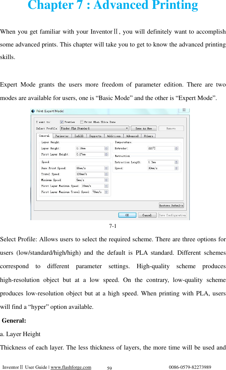
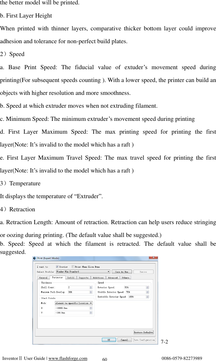
![InventorⅡ User Guide | www.flashforge.com 0086-0579-82273989 53 Chapter 6: Basic Printing This chapter will provide a step-by-step guide on turning a 3D model into a physical reality. Before proceeding, it is recommended that you’d better go over prior chapters on loading/unloading filament, leveling the build platform, and the functions and capabilities of FlashPrint. 6.1 Generate a Gcode (6-1)Double-click the icon of Flashprint to start the software. 6-1 (6-2)Click[Print]--[Machine Type] to select Flashforge InventorⅡ 6-2 (6-3)Click the [Load] icon to load a .stl model file and the object will display on the build area. 6-3 (6-4)Click [Edit]--[Surface to Platform] to make your model perfectly positioned on the build area. Click [Back] and double-click the Move icon again, then click [On the Platform] and [Center] to ensure the model be on the platform. 34](https://usermanual.wiki/Zhejiang-Flashforge-3D-Technology/INVENTOR2/User-Guide-3270333-Page-53.png)
![InventorⅡ User Guide | www.flashforge.com 0086-0579-82273989 54 6-4 Note:If you’ve place your model in a right place, you can skip the step above. (6-5) Click the Print icon on the top, you should make some setups for your print job. Preview: If you check the [Preview] box, you can preview your model after slicing is done. Print When Slice Done: If you print via USB cable, you can check the box, while if you print via USB, you should not check the box. Machine Type: Flashforge InventorⅡ 6-5](https://usermanual.wiki/Zhejiang-Flashforge-3D-Technology/INVENTOR2/User-Guide-3270333-Page-54.png)
![InventorⅡ User Guide | www.flashforge.com 0086-0579-82273989 55 Supports: If you print a model with supports, you should click the inverted triangle and select [Enable]. Raft: You are suggested to select [Enable]. Resolution: You are suggested to select [Standard] More Options: You are suggested to keep them default. Click [OK] to select the path to save the Gcode file. You can rename the file as you like and save it as a .g or .gx file, click [Save] to generate a Gcode file. 6-6 Note: .gx files are available for preview while the .g files are not. They are displaying as follows: g. Files gx. Files 6-7 Next, we are going to print the model.](https://usermanual.wiki/Zhejiang-Flashforge-3D-Technology/INVENTOR2/User-Guide-3270333-Page-55.png)
![InventorⅡ User Guide | www.flashforge.com 0086-0579-82273989 56 6.2 Print Methods After generating the Gcode file, you can transfer it to your InventorⅡ. You can transfer the file through USB cable and USB stick. 6.2.1 Print from Computer (USB connection) Connect your ①InventorⅡ with your PC via a USB cable. Turn on your ②InventorⅡ, level the build plate and load the filament. ③ Click [Print] and transfer your Gcode file to your InventorⅡ. After completing transference, the printer will heat up automatically. And when heating finishes, the print will start to build the model. 6-8 6-8 ④When your PC connects with FlashPrint successfully. The status box on the bottom right displays the real-time nozzle temperature. After finishing preheating, your InventorⅡ starts the print job directly. 6.2.2 Print from Computer (WIFI connection) ① Connect your InventorⅡ with your PC via WIFI. ② Turn on your InventorⅡ, level the build plate and load the filament. ③ Click [Print] and transfer your Gcode file to your InventorⅡ. After completing transference, the printer will heat up automatically. And when heating finishes, the printer will start to build the model.](https://usermanual.wiki/Zhejiang-Flashforge-3D-Technology/INVENTOR2/User-Guide-3270333-Page-56.png)
![InventorⅡ User Guide | www.flashforge.com 0086-0579-82273989 57 If you want to print a Gcode from a local folder, you just need to load the file into Flashprint at the status of USB connection or WIFI connection, then click the [Print] button on the top-right. ● Load the target Gcode file into FlashPrint. 6-9 ● Click the [Print] button, the PC will transfer the Gcode file to the printer. 7-10 ● After finishing transferring, the printer will heat up automatically. And when heating finishes, the print will start to build the model.](https://usermanual.wiki/Zhejiang-Flashforge-3D-Technology/INVENTOR2/User-Guide-3270333-Page-57.png)
![InventorⅡ User Guide | www.flashforge.com 0086-0579-82273989 58 6.2.3 Print from USB Flash Disk ①Insert your USB flash disk with target .g or .gx file to your InventorⅡ. ②Turn on the InventorⅡ. Make sure the build plate has been leveled and the filament is loaded. ③Tap [Print] and then tap the SD Card icon in the middle. The file(s) will be displayed on the screen. Select the file you want to print and tap [Print]. The file will be transferred to the printer. ⑥And the printer will heat up the nozzle automatically and start to print after the nozzle reaches the aimed temperature., Abort:To stop heating and printing. Once you tap [Abort], the process is irreversible. Pause:To suspend the print job, you can tap it again to resume it. You can use this function when you want to change the filament halfway.](https://usermanual.wiki/Zhejiang-Flashforge-3D-Technology/INVENTOR2/User-Guide-3270333-Page-58.png)
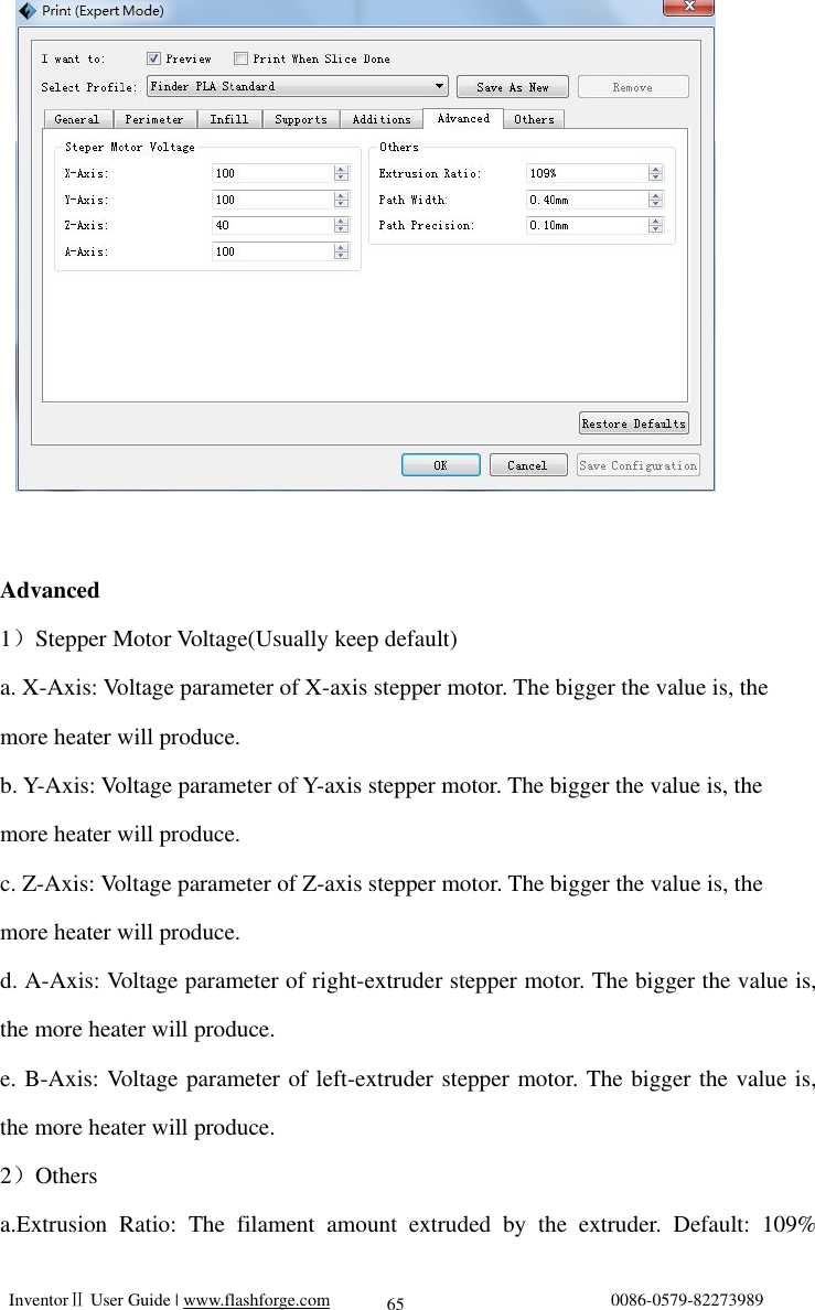
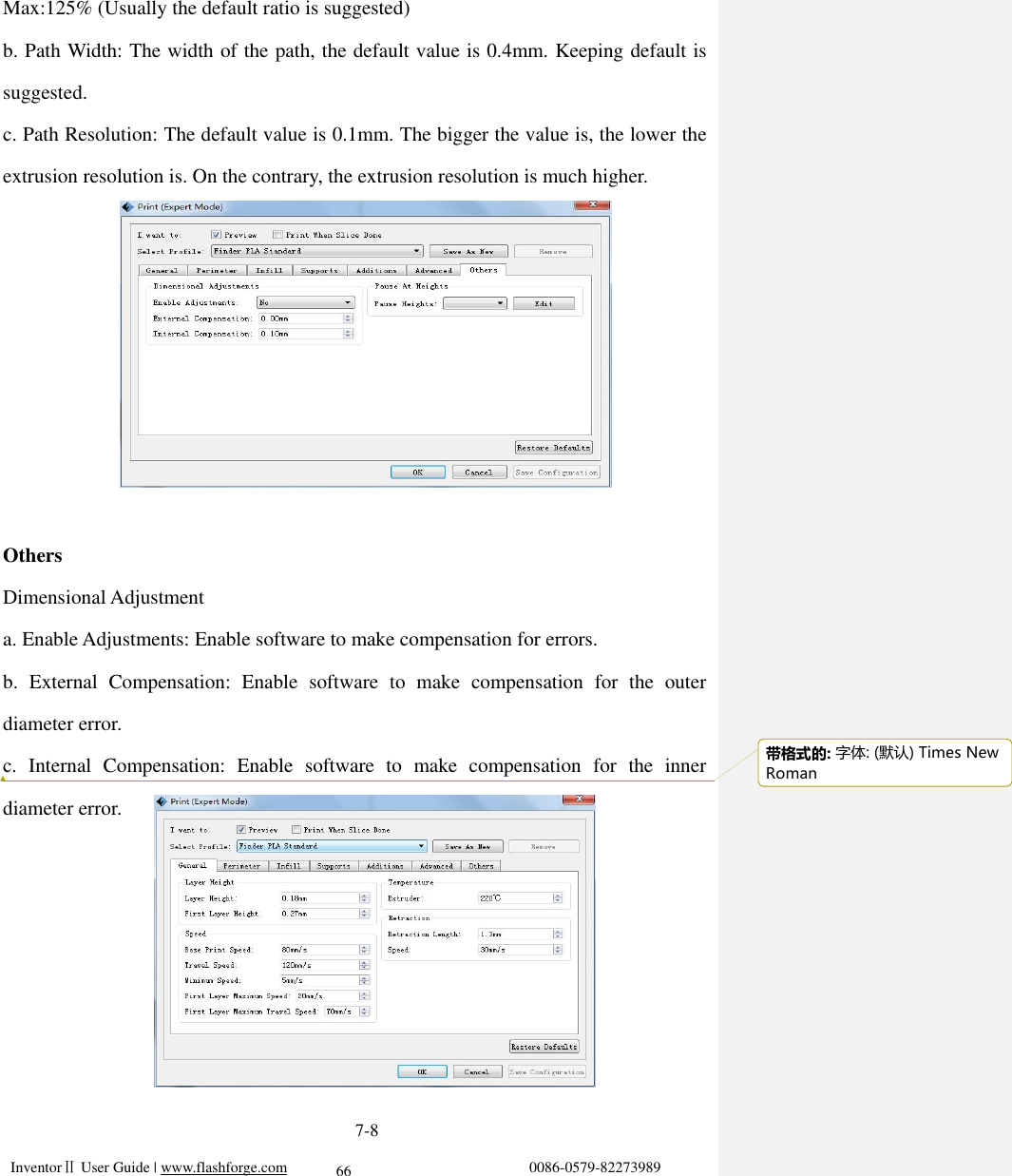
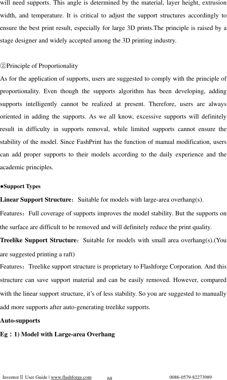
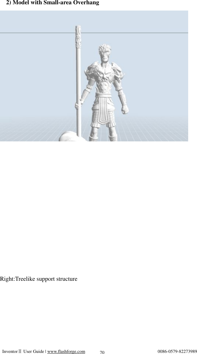
![InventorⅡ User Guide | www.flashforge.com 0086-0579-82273989 67 Save as new Allows users to save the model as a new file after parameter modification. How to do? After getting all the required parameters modified, click [Save as new], then a dialogue box will pop up. Users need to enter the file name into the box, then click [OK]. Click the drop-down menu of [Select Profile], the new added scheme can be found in the list. Remove Allows the users to delete the added scheme(s). Select one of the added schemes, click [Remove] and a dialogue box will pop up for confirmation. Click [Yes] to remove it or click [No] to cancel the current operation. Restore Default: Allows users to restore to the default settings. Save Configuration: Allows users to save the present configuration. 7.1 Skills on Supports (Reference Video:Skills on Supports) Support structures enable the printing of models with steep overhangs and cantilevered sections. The InventorⅡ 3D printer utilizes Fused Filament Fabrication (FFF) technology, which works on the additive manufacturing principle of heating and laying down material layer by layer to create an object. Many sophisticated 3D print designs require materials to be deposited on a layer where there was not a previous layer, or the designs have steep angles which might cause undesired drooping during the print. In these cases, support structures are needed to ensure objects integrity and print quality. Principle of 45 Degrees① Generally speaking, if the 3D model has an overhang of more than 45 degrees, you](https://usermanual.wiki/Zhejiang-Flashforge-3D-Technology/INVENTOR2/User-Guide-3270333-Page-67.png)
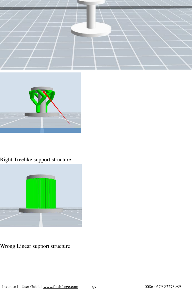
![InventorⅡ User Guide | www.flashforge.com 0086-0579-82273989 71 Wrong:Linear support structure Manual Modification 7-9 For the experienced 3D printer users, the [Add] and [Delete] buttons are suggested using for manually adding or deleting supports.](https://usermanual.wiki/Zhejiang-Flashforge-3D-Technology/INVENTOR2/User-Guide-3270333-Page-71.png)
![InventorⅡ User Guide | www.flashforge.com 0086-0579-82273989 72 1)Manual Add 7-10 You can add the support structure manually to according to the actual shape of the model. Left click [Add] on the left, and then click on the position when support structure is](https://usermanual.wiki/Zhejiang-Flashforge-3D-Technology/INVENTOR2/User-Guide-3270333-Page-72.png)
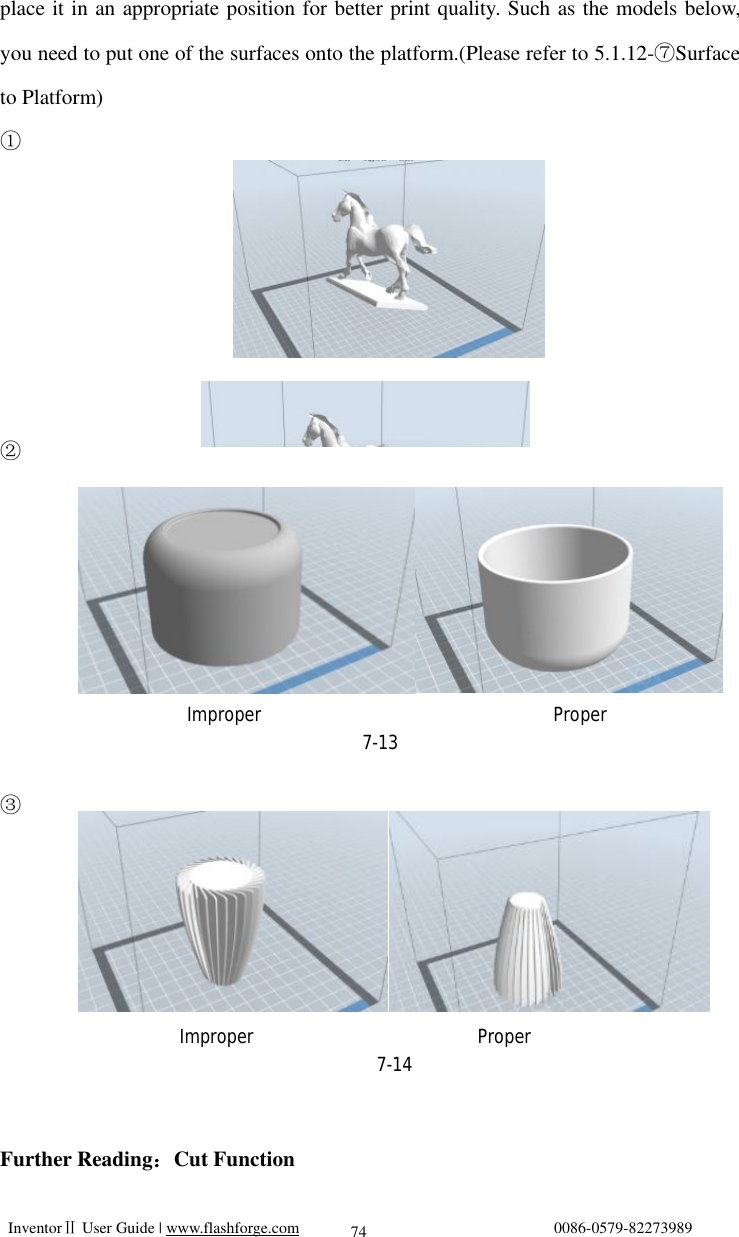
![InventorⅡ User Guide | www.flashforge.com 0086-0579-82273989 73 needed. Press down the left mouse button and drag to generate the support. 2)Manual Delete 7-11 Like the picture above, a hole inside the model doesn’t need any supports. Left click the [Delete] button and then left click the supports needed deleting. And the support will be deleted. 7.2 Control over Printing Quality Enhance the build plate adhesiveness① ● Leveling the build plate ● Keeping the build plate smooth and tidy ● Using the build tape or glue Adjusting the printing speed② ● Low (Fast) (Print Speed 80mm/s Travel Speed 100mm/s) ● Standard (Print Speed 60mm/s Travel Speed 80mm/s) ● High (Slow) (Print Speed 50mm/s Travel Speed 70mm/s) ● Hyper (Print Speed 50mm/s Travel Speed 70mm/s) 7.3 Skills of Model Placement Not all the models are in the right positions after being loaded. Therefore, you need to](https://usermanual.wiki/Zhejiang-Flashforge-3D-Technology/INVENTOR2/User-Guide-3270333-Page-73.png)
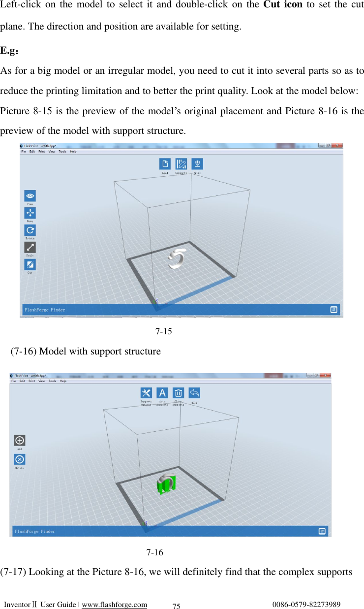
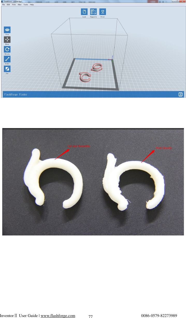
![InventorⅡ User Guide | www.flashforge.com 0086-0579-82273989 76 will influence the smoothness of the model. By analyzing the model’s feature, cutting from the Y plane will be suitable. 7-17 (7-18) The model preview after cutting. 7-18 (7-19) Click [Edit]--[Surface to Platform] to put the flat surfaces onto the platform.](https://usermanual.wiki/Zhejiang-Flashforge-3D-Technology/INVENTOR2/User-Guide-3270333-Page-76.png)