Zhejiang Flashforge 3D Technology POLAR3D20 POLAR 3D PRINTER User Manual part 2
Zhejiang Flashforge 3D Technology CO., Ltd. POLAR 3D PRINTER part 2
Contents
- 1. user manual part 1
- 2. user manual part 2
user manual part 2
CHAPTER 4. THE POLAR CLOUD 140
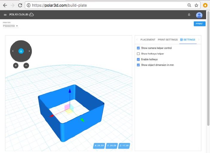
Figure 4.81: Polar Cloud build plate UI SETTINGS
4.6.1.1 The build plate screen: adding or extracting objects
You may load multiple objects to the build plate, adding objects
from other print jobs you have queued, or adding objects acces-
sible to you in the Polar Cloud, via the “Load Objects from
the Cloud”or“Load Objects from the Queue” icon buttons,
respectively.
When the build plate has multiple objects on it, stored in
separate files, you may also select particular such objects to copy
into your private collection of objects in the Polar Cloud: you
may extract such particular objects to store in the Polar Cloud.
See the “Upload Objects to the Cloud” icon button.
CHAPTER 4. THE POLAR CLOUD 141
4.6.2 Submit your print job to a printer and begin
printing
From the build plate screen, clicking the blue “PRINT” button
(at the upper right of the screen) submits your print job to
the currently selected printer (as shown in the upper left of the
build plate screen); see for instance Figure 4.81 (or for additional
discussion of build plate screen features, refer to Figure 4.78 in
Section 4.6.1).
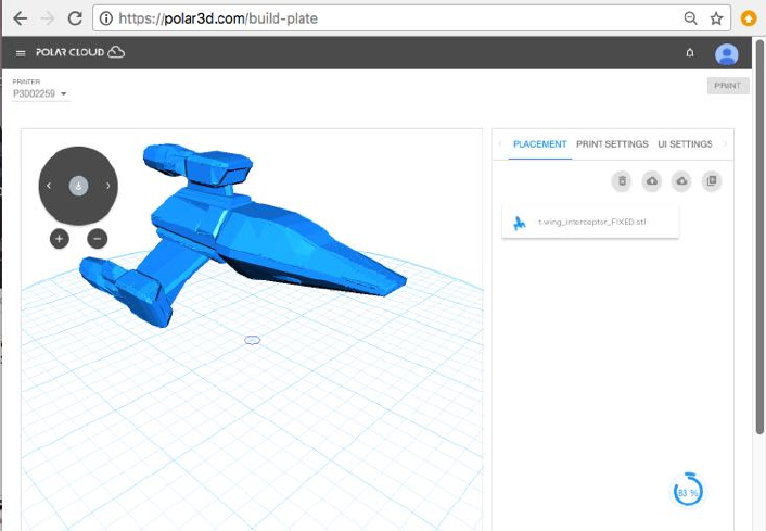
Especially if your object(s) have large .stl files,youmay
see a swirling blue icon (with a numeric progress value) towards
the lower left of the build plate screen after clicking “PRINT”,
as the job is submitted to the printer; the numeric value and
inner blue arc indicate how far the load has progressed, while
the swirl of the outer blue arc shows progress occurring; see
Figure 4.82.
Once your job is completely submitted, you will automati-
cally be taken to the printer dashboard screen, where you will
now see your job (as well as possibly other, previously submit-
ted, jobs) in the print queue; refer to Figure 4.86.
To actually begin the print of your ob ject, or whichever ob ject
is first in the queue, the printer owner or a printer manager (or
amember of a group with control access to the printer)must
click the “START” button on the printer dashboard screen (a
blue button, towards the upper right); Section 4.6.3 will further
discuss the printer dashboard control buttons such as “START”
and “STOP”. Of course, first you may want or need to perform
some preparation tasks such as: remove any previously printed
completed object o↵the build plate, touch-up the hair spray on
CHAPTER 4. THE POLAR CLOUD 142
Figure 4.82: Polar Cloud build plate screen: progress loading job to printer
the build plate,load or change filament,etc.
Before your print job begins printing, you may also choose
to modify it. And if you are a printer manager or have control
access to the printer, you may modify the queued jobs of other
members, perhaps shu✏ing the order of jobs, or merging jobs;
Section 4.6.4 will further discuss such print queue management
operations.
4.6.3 Printer dashboard control buttons
By default, the control buttons on the printer dashboard screen
are only active for the printer owner and any additional printer
managers, while members instead see these control buttons grayed-
out. For such printers, only the printer owner and any additional
CHAPTER 4. THE POLAR CLOUD 143
printer managers can trigger the actual start of a queued print
job (or pause or stop a job that is currently printing).
However, when a printer is shared with a group, there is
a group setting to allow members of the group to control the
printer. When that switch has been set ON,thenallmembersof
the group sharing the printer can also make use of the control
buttons.
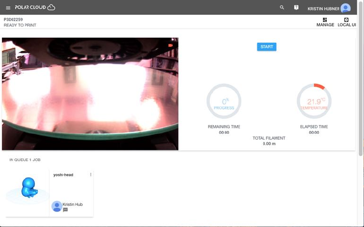
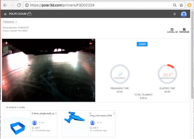
To trigger the start of the job at the head of the print queue,
click the “START” button on the printer dashboard screen; see
Figure 4.83.
Figure 4.83: Printer dashboard: job submitted and START button active
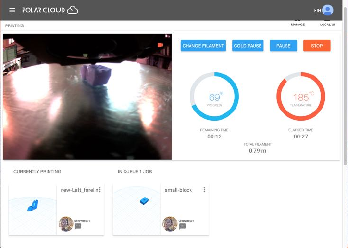
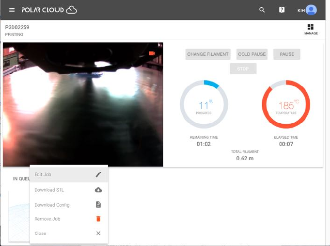
Once a job is printing, the control buttons “CHANGE FILAMENT”,
“COLD PAUSE”, “PAUSE”, and “STOP” appear; see Figure 4.84.
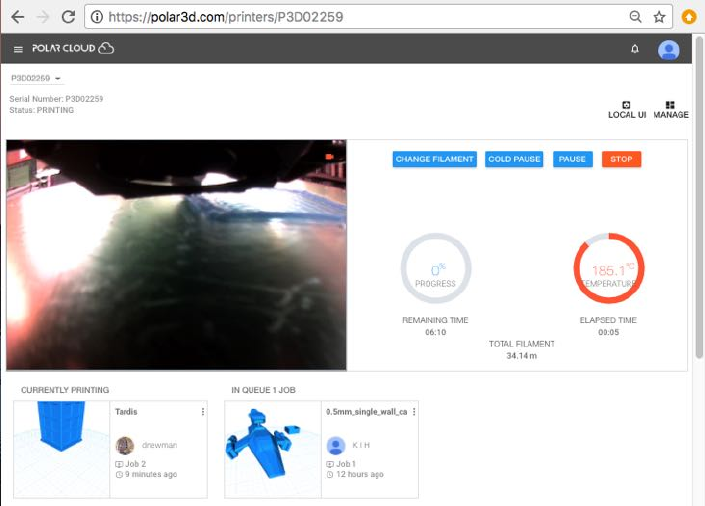
CHAPTER 4. THE POLAR CLOUD 144
Figure 4.84: Printer dashboard: control buttons active during job print
The “CHANGE FILAMENT” button pauses the print (performs
a “warm” pause), and backs out the current filament.
The “COLD PAUSE” button pauses the print, turning o↵the
heating element in the extruder. A “cold pause” is appropri-
ate when you do not wish to abort a partially printed object,
but you need some significant time to check (or fix) something
with the printer, or perhaps you need some time to obtain more
filament.
The “PAUSE” button performs a “warm” pause: it pauses
printing but keeps the heater(s) on and does not back out the
filament. As such, a “PAUSE” is appropriate when you want
to quickly check (or fix) something. But leaving the printer in
a “warm” pause for an extended period is not recommended:
CHAPTER 4. THE POLAR CLOUD 145
since the filament remains in the still hot extruder, during an
extended “warm” pause, melted filament may begin leaking onto
your build plate.
The “STOP” button cancels the print job: printing of the
current job stops, and all heaters are turned on. Note that the
print job is left in the queue (should you later wish to make a
fresh start on the print); if, however, you do not plan to ever
re-attempt this print job, you should delete the job from the
queue.
After performing a “CHANGE FILAMENT”, “COLD PAUSE",or
“PAUSE”, the control buttons that become available are “RESUME”
(to resume printing) and “STOP” (if you wish to turn your tem-
porary pause into a permanent cancel of the print job).
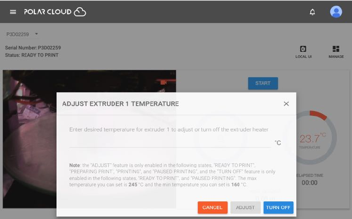
Figure 4.85: Polar Cloud printer dashboard ADJUST EXTRUDER TEMPERATURE
screen
CHAPTER 4. THE POLAR CLOUD 146
In addition to the control buttons, the printer dashboard also
allows controlling the printer temperature. Clicking on the tem-
perature dial will bring up a screen with an option to adjust the
printer temperature; see Figure 4.85.
4.6.4 Print queues in the Polar Cloud
The Polar Cloud maintains a print queue for each printer, allow-
ing multiple members (those Polar Cloud members authorized
to use that printer; see Section 4.5.5) to submit print jobs to
a printer; the Polar Cloud will submit each job in turn to the
actual printer.
From the printer management screen, see Figure 4.60, clicking
on “QUEUE” will show a display of jobs on the print queue. The
owner or a manager of a printer will see all jobs; similarly, a
member of a group configured to have printer control of any
shared printers will also see all jobs. But a Polar Cloud member
who is allowed to use the printer but who is neither the owner nor
a manager, (nor a member of a group configured to have control
of shared printers), will only see his or her own jobs.
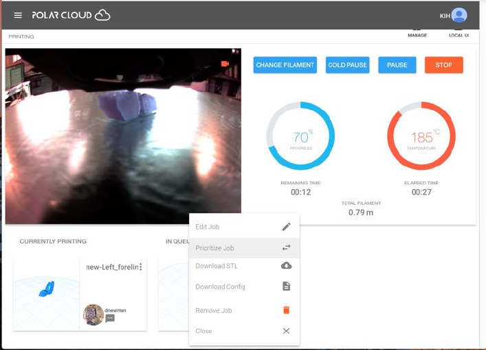
Note that the printer manager(s) may view all jobs in a print
queue, including jobs of other members; see Figure 4.86.The
printer manager(s) may also modify jobs in a print queue, in-
cluding those of other members; for instance, a printer manager
may delete jobs from the print queue, or rearrange the order of
the jobs in the queue. Clicking on the three vertical dots at the
top right of the icon for a job will bring up the menu of available
modifications; see for instance Figure 4.87.
CHAPTER 4. THE POLAR CLOUD 147
Figure 4.86: Printer dashboard: printer owner’s view of job queue
APolarCloudmember(whoisnot the owner nor a manager
of the printer, nor a member of a group with control access to
the printer)canseeandmodifyonlythoseprintjobsheorshe
submitted to the printer’s job queue, as well as seeing through
the printer dashboard a live view of whatever the printer is cur-
rently doing (which may be printing another member’s job).
Figure 4.88 shows an example of the printer dashboard screen
presented to a member who has one queued print job of their
own, waiting for another member’s print job to finish.
CHAPTER 4. THE POLAR CLOUD 148
Figure 4.87: Printer dashboard: printer owner’s job modification menu
CHAPTER 4. THE POLAR CLOUD 149
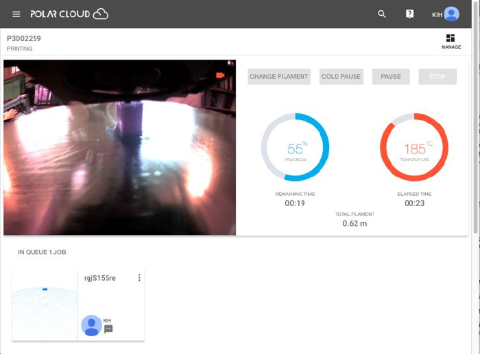
Figure 4.88: Printer dashboard: a member queued job waiting while another
member’s job prints
Note that the control buttons (towards the top right of the
screen) are all grayed-out when a member is viewing the printer
dashboard of a printer the member neither owns nor manages
(nor has control access permitted through group membership):
such a member cannot interrupt the printer’s current job. Nor
can such a member see what other jobs may be queued to the
printer before his or her own job(s); the member can only per-
form operations on their own print jobs (before they begin print-
ing), such as removing one of their own queued jobs, or edit-
ting/combining print jobs. Clicking on the three vertical dots
towards the upper right of the queued job icon (see Figure 4.88)
will bring up the options for modifying a queued job (see Figure
4.89).
CHAPTER 4. THE POLAR CLOUD 150
Figure 4.89: Printer dashboard: member options for editting their own
queued job
The Polar Cloud also maintains a history list of what has
been printed on the printer. From the printer summary dis-
play screen, see Figure 4.60,clickingon“HISTORY” will show
the history of what has been printed on the printer; see Figure
4.69.
4.6.4.1 Merging print queue jobs
Sometimes it may be convenient to merge multiple print jobs
– that is, to have the printer work on printing multiple objects
at once. Especially for small objects, printing multiple objects
at once (thus with built-in cooling time) may even yield bet-
ter results. And for printers accessed by multiple Polar Cloud
CHAPTER 4. THE POLAR CLOUD 151
members, printing multiple objects at the same time may lessen
wait time and contention for the printer.
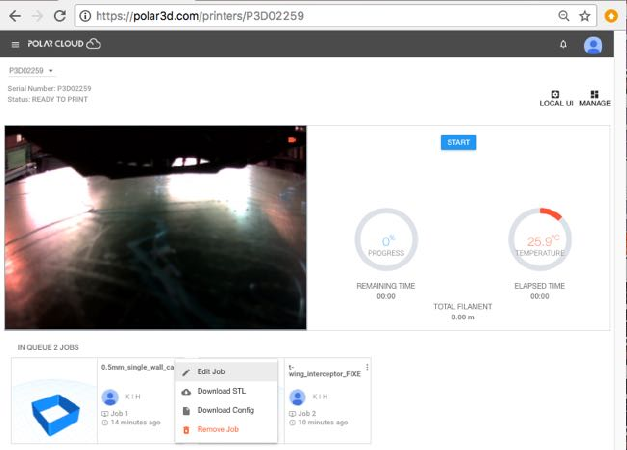
Suppose the print queue has multiple jobs queued; see Figure
4.90.
Figure 4.90: Two jobs in the print queue
Click on the three dots at the upper right of the first job, and
select “Edit Job”; see Figure 4.91.
CHAPTER 4. THE POLAR CLOUD 154
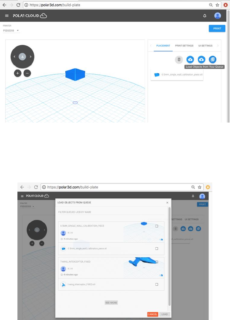
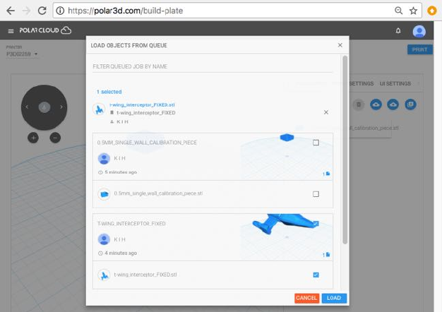
Check the box(es) for the jobs you wish to merge into the job
you’re editting, and then click the blue “LOAD” button (towards
the lower right); see Figure 4.94.
Figure 4.94: Selecting which objects to load from the print queue
The additional object(s) will now also be loaded to the build
plate; see Figure 4.95.
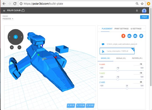
CHAPTER 4. THE POLAR CLOUD 155
Figure 4.95: Build plate: additional queued object loaded
Click the “PRINT” button (towards the upper right) to submit
this merged job to the printer; a pop-up “SAVE PRINT JOB”
screen will ask whether you wish to “SAVE TO EXISTING PRINT
JOB” (replacing the print job you originally chose to edit) or
“CREATE NEW PRINT JOB” (submit a newly created print job in
addition to your original print jobs); see Figure 4.96.
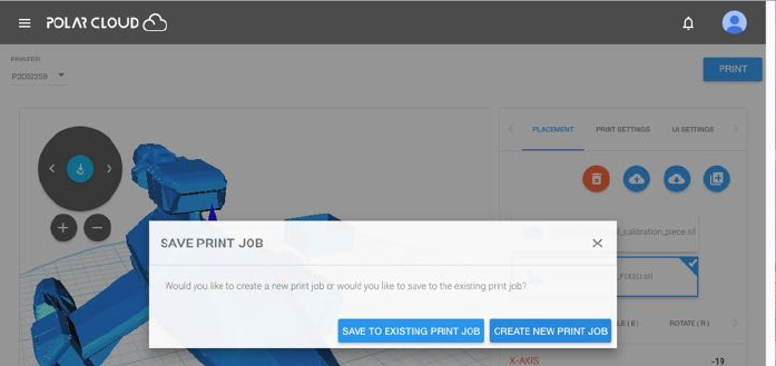
CHAPTER 4. THE POLAR CLOUD 156
Figure 4.96: Build plate: choose whether merged job replaces original job or
becomes a new job
If you click “CREATE NEW PRINT JOB”, then at the printer
dashboard you will now see three queued jobs, the two original
jobs plus a third job which has both objects; see Figure 4.97.If
you wish, you may now remove either or both of the original two
print jobs: click on their three dots and select “Remove Job”;
see Figure 4.98.
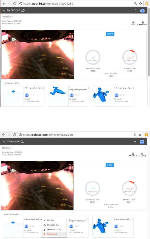
CHAPTER 4. THE POLAR CLOUD 157
Figure 4.97: Merged job present in print queue
Figure 4.98: Remove redundant jobs from the print queue
CHAPTER 4. THE POLAR CLOUD 158
4.6.4.2 Move a print job to a di↵erent printer
If you have access to multiple printers, then a print job that is
pending in one printer’s print queue may be moved to a di↵erent
printer. To do this, go to the printer dashboard, click the three
dots at the upper right of the print job icon, and click “Edit
Job” to return to the build plate screen for the print job. Then
select the desired printer from the printer drop-down menu (to-
wards the upper left of the build plate screen) and click “PRINT”
to resubmit the print job to the newly chosen printer.
Moving a print job is most often performed just for con-
venience and efficiency of managing printer use: e.g.,adif-
ferent printer might be currently unused and ready to print,
or might already have desired filament loaded. However, an-
other case that can arise is when the printer local web interface
“Reset Printer on the Polar Cloud” tab has been used to
obsolete a prior use of the printer. When a printer has been
obsoleted in the Polar Cloud, any print jobs that had been
pending in its print queue remain in the Polar Cloud, not ac-
tively printing but instead assigned to the “obsolete” printer
(re)named ‘P3Dserial-digits -deleted-date ,sothatifde-
sired, such print jobs may be editted to reassign them to a dif-
ferent printer.
4.6.5 Real-time video or updated snapshots of jobs in-
progress
When you submit an object to be printed (press “PRINT”onthe
“3D PRINT” screen), the Polar Cloud display will automatically
CHAPTER 4. THE POLAR CLOUD 159
go to the dashboard screen for your selected printer,showing
what the printer is currently doing.
If you are connected to the same local network to which the
printer is connected, the printer dashboard will show live video
of what the printer is currently doing. If you are connected to the
Polar Cloud through a di↵erent local network, the printer dash-
board will instead display frequently updated (updated about
every five seconds) still snapshots of what the printer is cur-
rently doing.
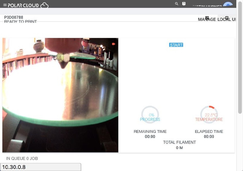
If your job is at the head of the printer’s job queue,you
will see your job printing. Once your job has begun printing,
a“STOP” button will appear; you may press that button if you
wish to stop (abort) the print job.
If you are the owner or a manager of the printer, you will see
on the printer dashboard “START” button; press that button to
begin your print.
Note that time-lapse video of the print job is also available
later in the printer history; see Section 4.5.7.
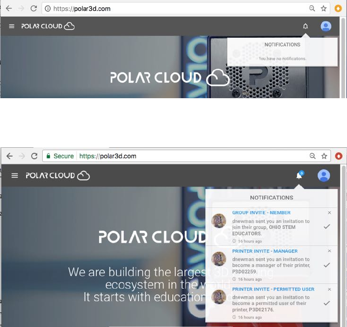
4.7 Notifications in the Polar Cloud
Hovering over the bell icon, towards the upper right of a Po-
lar Cloud screen, will display a summary of any notifications
(such as invitations to access a printer or join a group)thatyou
may have. When a number appears on the bell, it represents
how many pending notifications are awaiting your attention; see
Figure 4.100.
CHAPTER 4. THE POLAR CLOUD 160
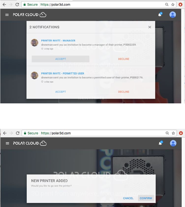
Figure 4.99: Polar Cloud notifications
Figure 4.100: Polar Cloud notifications: three pending
When you invite a fellow Polar Cloud member to become a
member of one of your groups,orinvite a fellow Polar Cloud
member to become a user or manager of a printer that you own
or manage, that Polar Cloud member will receive an invitation
notification.
CHAPTER 4. THE POLAR CLOUD 161
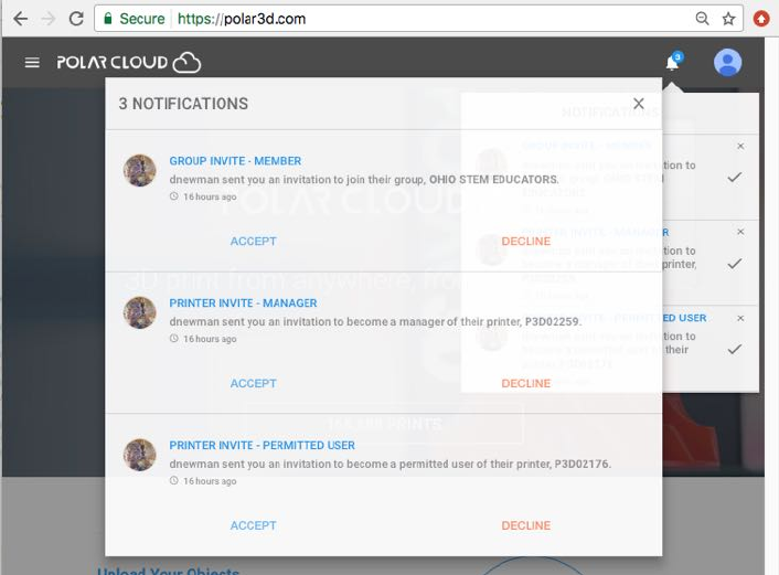
Figure 4.101: Polar Cloud invitations
4.7.1 Responding to an invitation notification
Clicking on the bell icon, towards the upper right of a Polar
Cloud screen, will display the list of notifications awaiting your
attention; see Figure 4.101.
Figure 4.101 shows a range of the possible types of invitations:
an invitation to join a group, an invitation to become a manager
of a printer, and an invitation to become a user of a printer.
Note that the issuer of an invitation is not explicitly informed
of your action on the invitation (in particular, no response no-
tification back to the invitation issuer is generated when you
“DECLINE” an invitation), though if you do “ACCEPT” an invita-
tion, the issuer will thenceforth see, when looking at a group or
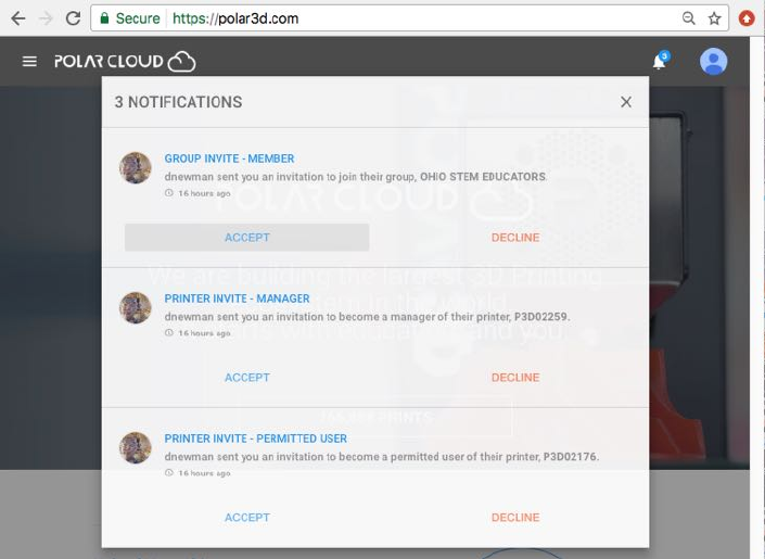
CHAPTER 4. THE POLAR CLOUD 162
printer, that you are a member of the group or have access to
the printer.
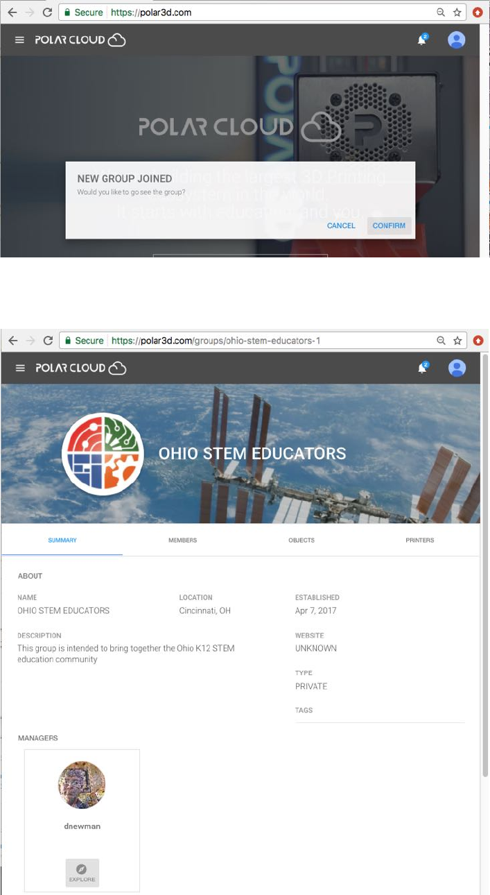
When you “ACCEPT” an invitation to join a group, see Figure
4.102, a confirmation that you joined will appear and you will
have the opportunity to go see the group; see Figure 4.103.
Figure 4.102: Polar Cloud ACCEPT a group invitation
Clicking on the “CONFIRM” button in Figure 4.103 will take
you to the group’s SUMMARY display page, as shown in Figure
4.104.
CHAPTER 4. THE POLAR CLOUD 163
Figure 4.103: Polar Cloud confirmation of joining a group
Figure 4.104: Polar Cloud SUMMARY display of group upon accepting invita-
tion to join
CHAPTER 4. THE POLAR CLOUD 164
When you “ACCEPT” a printer access invitation, whether that
invitation is to become a manager (see Figure 4.105)orauser,
a confirmation that you may now access the printer will appear
and you will have an opportunity to go directly to that printer’s
dashboard; see Figure 4.106.
Figure 4.105: Polar Cloud: invitation to manage a printer
Figure 4.106: Polar Cloud confirmation of printer access
CHAPTER 4. THE POLAR CLOUD 165
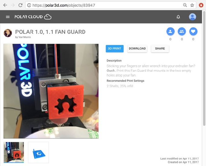
Figure 4.107: Polar Cloud object detail, by Van Morris
4.8 Viewing other Polar Cloud members
Clicking on the icon of a Polar Cloud member, whether that
icon appears on an object detail page (e.g.,seetheupperleftof
Figure 4.107), group member list, printer member list, or in the
activity list for your account (so a user of a printer of yours),
will take you to a Polar Cloud member page for that member,
such as shown in Figure 4.108.
Note that student Polar Cloud members are typically mem-
bers of “PRIVATE”or“MODERATED” class groups. Therefore, un-
less a student has posted (that is, shared) a “PUBLIC OBJECT”,
students typically are not visible to general Polar Cloud mem-
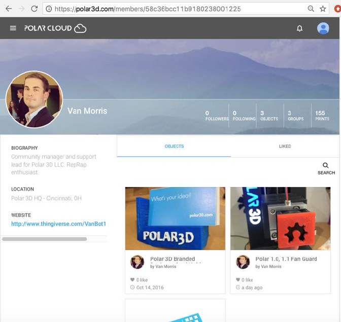
CHAPTER 4. THE POLAR CLOUD 166
Figure 4.108: Polar Cloud member Van Morris
CHAPTER 4. THE POLAR CLOUD 167
bers; students are typically visible only to other members of
their own class groups and their class groups’ managers (typi-
cally their own teacher(s)).
4.9 Collaborating through the Polar Cloud
You may share ob jects you have created or printed through the
Polar Cloud, either with all Polar Cloud members, or with mem-
bers in particular groups, or only with specific other Polar Cloud
members. To share an object simply click the “SHARE” but-
ton (under “OBJECTS”, “MY PRIVATE OBJECTS”or“MY SHARED
OBJECTS”, the object itself), and then choose with whom to
share the object; see Section 4.2.2 or Section 4.10. An alterna-
tive, more group-centric, way to share objects with a group is
also discussed in Section 4.4.5.
Note that your descriptions of objects and any printing rec-
ommendations or tips you wish to provide, and possibly photos
of your printed object, see Section 4.2.4, may be particularly
useful to other members when you share objects.
You may also search for and find and use objects that others
have shared within the Polar Cloud; see Section 4.2.2. (Note how
it is useful when other members provide detailed descriptions
and helpful printing tips for their objects!)
You may allow others to access your printer(s) – share your
printer(s) – through the Polar Cloud. To make your printer ac-
cessible to particular, specified Polar Cloud members, see Sec-
tion 4.5.5;toallowaccesstoyourprintertoallmembersin
specified groups, see Section 4.4.6.
CHAPTER 4. THE POLAR CLOUD 168
If others have made their printer(s) accessible to you, you can
use others’ printers. Accessible printers will show up in the list of
printers displayed by selecting “PRINTERS” from the Polar Cloud
left-hand top menu; see Figure 4.55 (or Figure 4.110).
You may create groups of Polar Cloud members with a shared
characteristic (e.g.,studentsinaclass)orsharedinterests. A
group is a particularly convenient way to share objects and share
(access to) printers. See Section 4.4.
You may “LIKE” the objects of other members, and they may
“LIKE” your objects; see Section 4.2.6.“LIKE”s are tallied and
displayed along with the object (both in the icon displays of lists
of objects, and on the object’s screen).
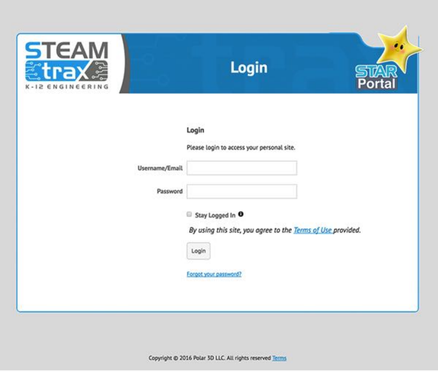
4.10 Navigating through the Polar Cloud user
interface
Go to http://polar3d.com and you will see the login screen, as
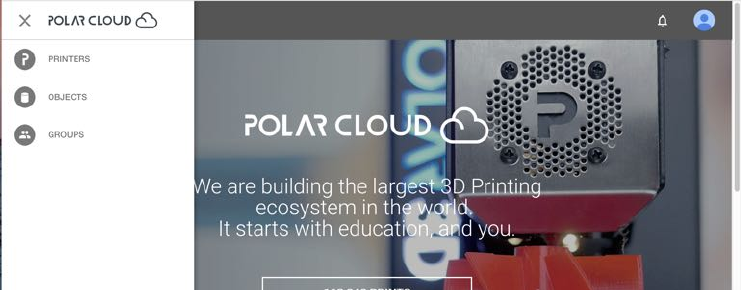
shown in Figure 4.2.Onceyouhaveloggedin,themainscreen
has an expandable menu icon at the upper left, with choices
“PRINTERS”, “OBJECTS”, and “GROUPS”; see Figure 4.109.
CHAPTER 4. THE POLAR CLOUD 169
Figure 4.109: Polar Cloud top menu
The main screen also has a drop down menu under the ac-
count name at the upper far right, with choices “Settings”,
your account email, and “Sign Out”; see Figure 4.1. And just
to the left of the account drop down menu is a bell icon, for
notifications.
You can return to the main screen from other Polar Cloud
screens by clicking on the cloud icon towards the upper left.
4.10.1 Navigating the printers
Under “PRINTERS” will appear a list of printers (which can either
be displayed via photos or via names – the icons for switching
between views), a tab to “ADD”aprinter,andatabto“SEARCH”
for a printer (relevant if you have many accessible printers).
For an example of the thumbnail view, see Figure 4.55;foran
example of the list view, see Figure 4.110.
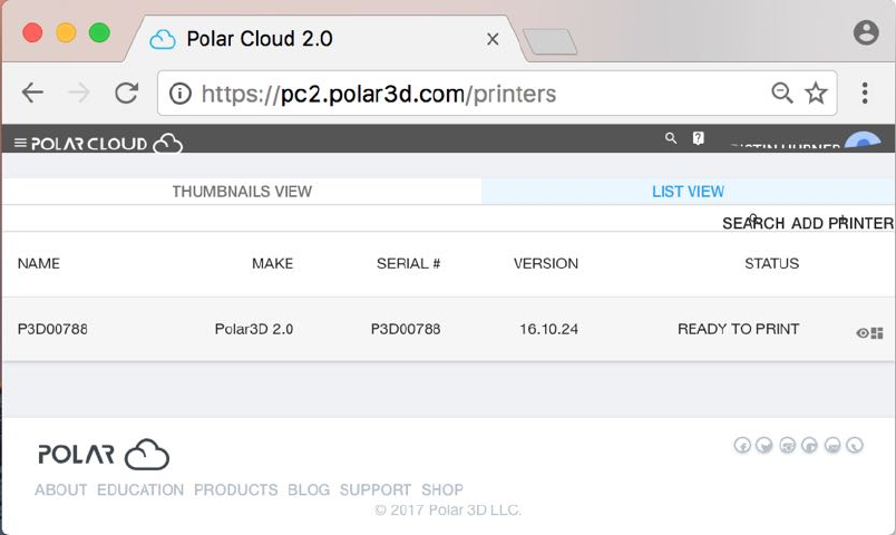
CHAPTER 4. THE POLAR CLOUD 170
Figure 4.110: Polar Cloud PRINTERS list view screen
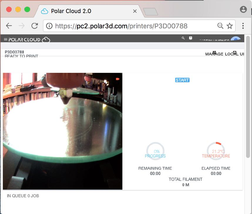
Clicking on a specific printer from the “THUMBNAIL VIEW”
(or clicking on the eye icon on that printer’s line in the “LIST
VIEW”) will take you to the printer’s dashboard screen, such as
shown in Figure 4.111.
Clicking on the “MANAGE” tab from the printer dashboard (or
on the squares icon on that printer’s line in the “LIST VIEW”)
will take you to the printer management screen, such as shown
in Figure 4.112. On the printer management screen are tabs
“QUEUE” (display the current queue of jobs submitted to the
printer), “HISTORY” (display the recent jobs printed on that
printer), and “MEMBERS” (control which members may use the
printer, and which members are considered managers of the
printer).
(Note that “DASHBOARD”and“MANAGE”takeyoubackand
CHAPTER 4. THE POLAR CLOUD 171
Figure 4.111: Polar Cloud printer DASHBOARD screen
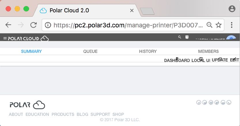
CHAPTER 4. THE POLAR CLOUD 172
Figure 4.112: Polar Cloud printer management screen
forth between the printer dashboard screen and the printer man-
agement screen.) On either the dashboard or management
screen, clicking the “LOCAL UI” tab will cause the Polar Cloud
to attempt to connect back (over the Internet) to the printer’s
local interface (via its local IP address); see Section 4.5.9 and
Chapter 5.
4.10.2 Navigating the objects
Expanding the Polar Cloud main screen’s top left-hand menu
and clicking “OBJECTS” (see Figure 4.8)willtakeyoutothe
OBJECTS screen (Figure 4.9)withtabsforcategoriesofobjects:
“MY PRIVATE OBJECTS”, “MY SHARED OBJECTS”, and “PUBLIC
OBJECTS”. Under each of these tabs, you may select (click on)
any available object, or click a tab to “UPLOAD”or“SEARCH”for
an object.
CHAPTER 4. THE POLAR CLOUD 173
Clicking on the icon for an object itself will take you to a
screen where (for one of your private objects) you may “3D
PRINT”, “DOWNLOAD”, or “SHARE” your object, or “EDIT”the
object’s text description; see Figure 4.10.Forsharedobjects,
you have similar choices “3D PRINT”, “DOWNLOAD”, or “SHARE”
(with “EDIT” the object text description not available for shared
objects).
For any ob ject, you may also “LIKE” the object by click-
ing on the heart icon (towards the upper right of the object
screen).
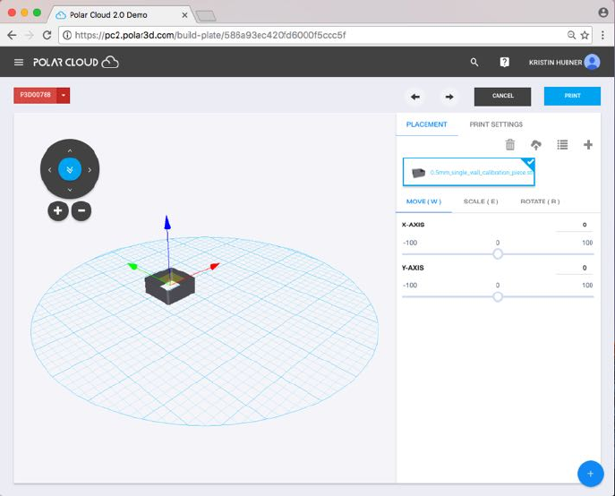
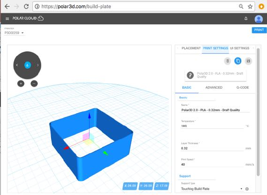
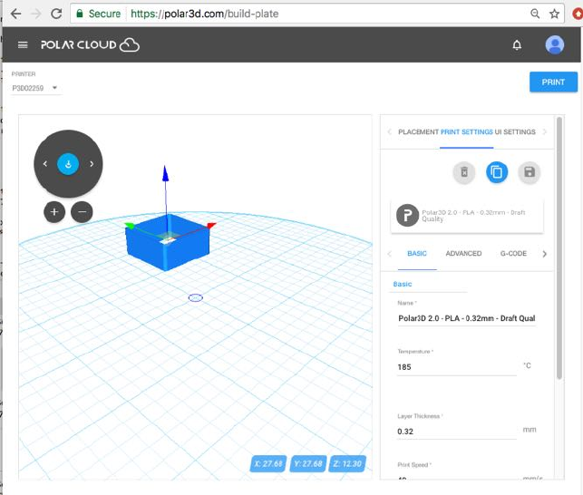
Clicking on “3D PRINT” takes you to a screen where you may
adjust “PLACEMENT” (position on the build plate) and “PRINT
SETTINGS”, or click the “PRINT” button when you are ready to
print; see Figure 4.78.
Under “PLACEMENT”, you may “MOVE”, “SCALE”, and “ROTATE”
the object:
CHAPTER 4. THE POLAR CLOUD 174
In the left hand side of the window, the object is schematically
pictured on the build plate, with three colored axes (red for the
x-axis, green for the y-axis, and blue for the z-axis), a “+”and
“-” button, and a dial with four arrows around the outside and a
central “restore” double arrow. The “+”and“-” buttons zoom
in and zoom out, respectively, your view of the object, and the
dial rotates your view of the object. The colored axes may be
used to reposition the object on the build plate: position your
cursor over an axis and drag the object along that axis.
In the right hand side of the window, you may select “MOVE”,
“SCALE”, or “ROTATE”.
When “MOVE” is selected, as an alternative to dragging the
object on the build plate, you may instead move the object on
CHAPTER 4. THE POLAR CLOUD 175
the build plate via the “X-AXIS”and“Y-AXIS” sliders under
“MOVE” in the right hand side of the window
When “SCALE” is selected, you may change the size of the
object via any of the “X-AXIS”, “Y-AXIS”, or “Z-AXIS” sliders
under “SCALE” in the right hand side of the window.
When “ROTATE” is selected, you may rotate the object via
the “X-AXIS”, “Y-AXIS”, and “Z-AXIS” sliders under “ROTATE”
in the right hand side of the window.
Under “PRINT SETTINGS”:
1. You may adjust “BASIC” settings relating to: “Basic” set-
tings such as extruder “Temperature” (a fundamental set-
ting that must be aligned with the type of filament you
are printing), “Layer Thickness”, and “Print Speed”; or
“Support” settings such as “Support Type” (where if your
object is not actually touching the build plate, you may
wish to add a type of support), or “Platform Adhesion
Type” (which is where you may add a brim,raft,orskirt).
CHAPTER 4. THE POLAR CLOUD 176
2. You may adjust “ADVANCED” settings relating to: “Fill”
(infill) such as “Infill Speed,“Infill Overlap”, and
“Infill Amount”; “Filament”suchas“Diameter”and
“Flow”; “Retraction”suchas“Amount Extruder Switch”
(the amount to retract or raise the extruder when switching
between extruders on a dual-extrusion 3D printer), “Speed”
(the speed at which to perform the retraction –tooquicka
speed may “yank” up just-extruded filament whereas very
slow retraction simply wastes time), “Amount” (the height
by which to raise the extruder); “Quality” (which might
be more alternately described as thickness of the exterior
of the print object) such as “Initial Layer Thickness”,
“Extrusion Width”, “Wall Thickness”, “Bottom Layer
Count”, and “Top Layer Count”; “Speed (which goes into
more detail than the basic “Speed” setting under “BASIC
options) including among other things “Initial Layer Speed”
(as printing the initial layer ; and “Cool”suchas“Minimal
Layer Time”and“Cooling Fan” (only relevant if your
printer has a cooling fan).
3. You may adjust via the “G-CODE” tab the actual starting
and ending Gcode that will be sent to the printer.
4.10.3 Navigating the groups
From the Polar Cloud’s main screen left-hand menu, clicking
“GROUPS” will take you to the GROUPS screen with its main
tabs for “MY GROUPS”and“PUBLIC GROUPS”, as shown in Fig-
ure 4.33. When “MY GROUPS” is active, tabs to “SEARCH”and
“CREATE” a group are available; when “PUBLIC GROUPS”isac-
tive, only “SEARCH” is available.
Chapter 5
The printer local web
interface
If you are controlling your printer directly through its local WiFi
(see Section C.1) rather than going through the Polar Cloud,
then the printer’s local web interface will be your main con-
trol interface. From a device on your local network (computer,
tablet, or phone), simply open a browser window connecting to
the printer’s local IP address and you will be at the printer local
web interface.
If you connect your printer to the Polar Cloud, then after
performing its initial connection (see Chapter 1), you likely will
seldom have a need or interest in connecting directly to the
printer’s local web interface. However, the printer’s local web
interface is still accessible. If you are on the same local network
as the printer, you may simply open up a browser window and
connect to its local IP address without going through the Polar
Cloud. Or from within the Polar Cloud, navigate from the main
menu to your list of printers, then click on the printer itself, and
then click on the LOCAL UI tab (settings dial towards the upper
177
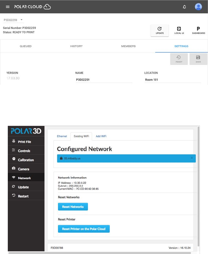
CHAPTER 5. THE PRINTER LOCAL WEB INTERFACE 178
Figure 5.1: Polar Cloud printer dashboard shows LOCAL UI tab
right), shown in Figure 5.1
The Polar Cloud will then attempt itself to connect to what
it knows as the printer’s local IP address. If your local network
permits access to the printer’s local IP address from the Inter-
net (which some local networks may not), this will open a new
window onto the printer local web interface, as shown in Figure
5.2.
(If your local network does not permit such access from the
Internet, then you may still connect to the printer’s local web
interface more manually, by simply connecting directly to its
local IP address, as previously mentioned.)
CHAPTER 5. THE PRINTER LOCAL WEB INTERFACE 179
Figure 5.2: Printer local web interface as viewed from Polar Cloud
CHAPTER 5. THE PRINTER LOCAL WEB INTERFACE 180
5.1 Navigating through the printer local web
interface
Connecting to the printer’s local IP address will put you at the
network screen. This is the same screen you would see if you
selected the networking icon on the left menu; see 6.
The tabs/icons at the left of the screen select additional
screens:
1. POLAR3D – the default (network) screen.
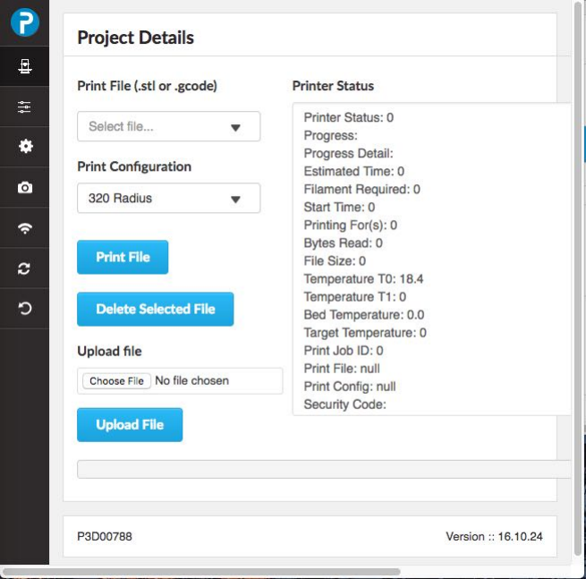
2. The printer icon (“Print File”) selects the “Project Details”
screen, where you may upload a file to print, or select an
already available file to print (as the Polar3D printer’s user
interface ships with several test .stl files), and then initi-
ate printing. This screen also displays, on the right hand
side under “Printer Status”, various status information
regarding the printer.
CHAPTER 5. THE PRINTER LOCAL WEB INTERFACE 181
Figure 5.3: Printer local web interface Print File (Project Details)
screen
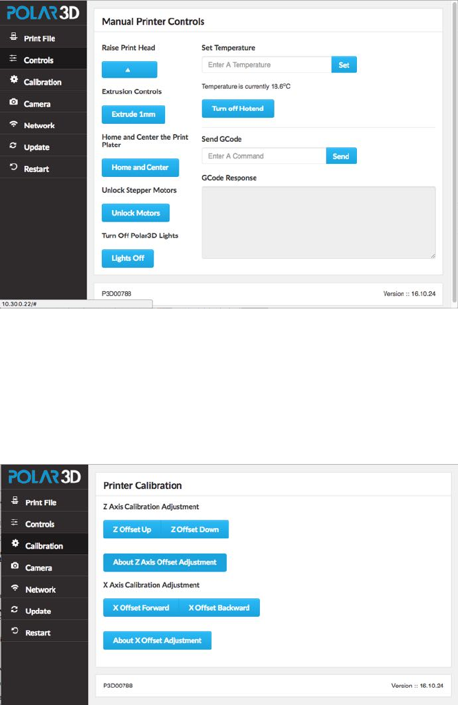
3. The lines-with-boxes icon (Controls). At this screen, you
may manually direct the printer; e.g., raise the print head,
set the temperature, extrude a millimeter of filament, turn
on/o↵the printer’s LED lights, unlock the stepper mo-
tors (so that the print head and build plate shuttle may
be moved manually), etc.
CHAPTER 5. THE PRINTER LOCAL WEB INTERFACE 182
Figure 5.4: Printer local web interface Controls screen
4. The dial/gear icon (Calibration)willtakeyoutothe“Calibration”
screen, where you may perform Z axis (Zrod)andXaxis
(build plate shuttle) calibration.
Figure 5.5: Printer local web interface Calibration screen
CHAPTER 5. THE PRINTER LOCAL WEB INTERFACE 183
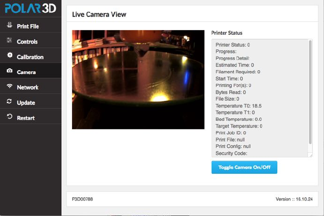
5. The camera icon (Camera)takesyoutoascreenshowing
live camera feed from the printer, and various printer status
details.
Figure 5.6: Printer local web interface Camera screen
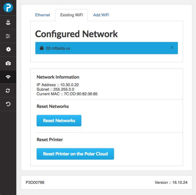
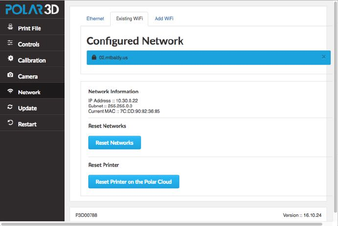
6. The network icon (Network)iconwilltakeyoutothe“Configured
Network” screen, where you may see what network the
printer is on currently and the printer’s own IP address
on that network, and even switch to a di↵erent network.
CHAPTER 5. THE PRINTER LOCAL WEB INTERFACE 184
Figure 5.7: Printer local web interface Network screen
Note that the Reset Networks button will remove any
configured network profiles, resetting the printer’s network
knowledge back to factory defaults. Thus you would not
normally want to click this button except when perma-
nently transferring the printer to an entirely new location
(entirely di↵erent network milieu) or owner! (If you are
merely temporarily moving your own printer to another
network, it is more convenient to instead add the new WiFi
network or plug in the Ethernet cable, and then use the
“Restart” tab on the left pane to have the printer recon-
nect using the newly added network; see step 7 in Section
1.1.Thenyoucanswitchbacktotheoriginalnetwork
later, by selecting that network and then again clicking
“Restart”, without having to entirely redo the network
profile.)
CHAPTER 5. THE PRINTER LOCAL WEB INTERFACE 185
Note that the “Reset Printer on the Polar Cloud” but-
ton on the “Configured Network” screen will obsolete any
existing ownership of this printer in the Polar Cloud. That
is, any Polar Cloud members who had formerly been the
owner of or been allowed access to this printer will now
no longer see the P3Dserial-number printer, and instead
will see a reference to P3Dserial-number -deleted-date .
(Such members may wish to move any queued jobs that
had been on that printer to some other printer.) Thus you
would not normally want to click this button except when
transferring ownership of the printer to some other per-
son (some other Polar Cloud member). After clicking this
button, the printer will need to be re-registered to some Po-
lar Cloud account in order to be used by any Polar Cloud
members; see step 10 of Section 1.1.
Thus both the buttons Reset Networks and even more so
Reset Printer on the Polar Cloud are primarily of in-
terest when transferring the printer to another owner.
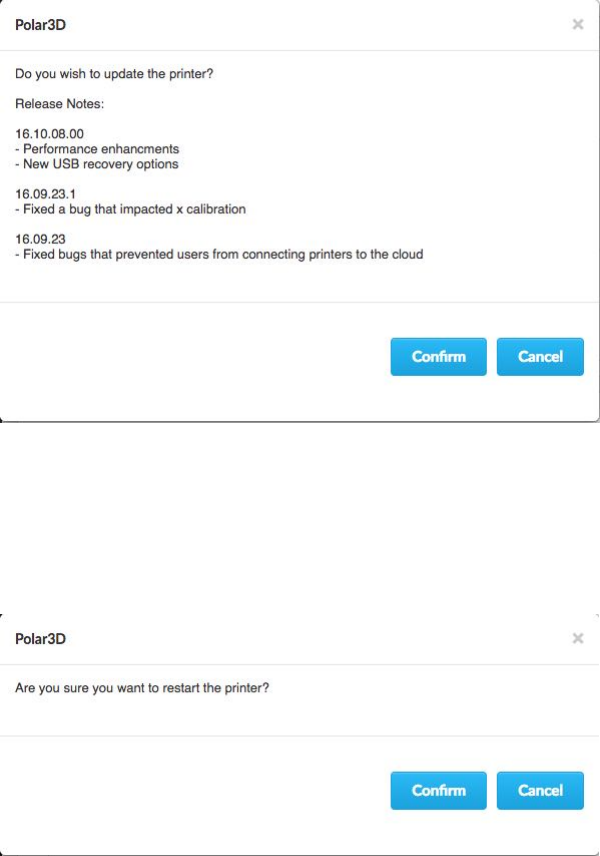
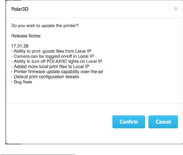
7. The update icon (Update)ifclickedwillshowyouasum-
mary of any current update, and ask if you wish to apply
that update:
CHAPTER 5. THE PRINTER LOCAL WEB INTERFACE 186
Figure 5.8: Printer local web interface Update screen
8. The restart icon (Restart)willaskifyouwishtorestart
the printer:
Figure 5.9: Printer local web interface Restart screen
Chapter 6
CAD software – create your
own objects
There are many computer-aided design (CAD) software pack-
ages available; for 3D printing, you will just need a package
that can save object files in .stl file format.
The Polar Cloud itself provides access to some convenient
CAD software you can access and use – see Section 4.3. Alter-
natively, if you prefer you may use many popular CAD packages
of your choice to generate .stl files.
For younger designers or beginners, we recommend Tinker-
cad.Itisabrowser-baseddesignprogramsonosoftwareneeds
to be installed locally. This makes it a great solution for Chrome-
books.
Sketchup is another good solution for designing 3D parts.
Make sure to install the STL plugin so you can export your
design for 3D printing.
Autodesk Fusion 360 is higher-level CAD software provided
187
CHAPTER 6. CAD SOFTWARE – CREATE YOUR OWN OBJECTS188
on a cloud platform, available free to students and hobbyists,
and available for Mac or PC.
Autodesk 123D Design,OnShape,andMorphi are good apps
for iPad users. They have free versions (123D) or free for educa-
tion versions (OnShape), or free with limitations (Morphi) and
you can pay to unlock all the features. Morphi o↵ers discount
pricing for schools based on the number of seats purchased.
Blender is an open-source design package that can also be
used for 3D animation, so time spent learning this tool means
students can do more than just create models for printing.
OpenSCAD is open-source software for creating 3D CAD ob-
jects, with a focus on programming and engineering.
Sculptris is focussed on art, and in particular, virtual sculpt-
ing.
Note that AutoDesk o↵ers several professional design soft-
ware packages that are for free to students and teachers. Some
have already been listed above, but to list a few more with com-
parisons:
1. Autodesk 123D Design is a good intermediate design tool.
2. Autodesk Fusion 360 is higher-level CAD software provided
on a cloud platform.
3. Autodesk Maya is an animation package that can be used
for 3D modeling.
4. Autodesk Inventor is a mechanical design and 3D CAD
software package that o↵ers professional-grade 3D mechan-
ical design, documentation, and product simulation tools.
This is good for advanced users who need exact tolerances
CHAPTER 6. CAD SOFTWARE – CREATE YOUR OWN OBJECTS189
in designs that they are creating.
Chapter 7
STEAMtrax curriculum
STEAMtrax is an innovative new curriculum that integrates en-
gineering and 3D printing technology with core academic knowl-
edge in science, math, language arts, social studies, and art. In
the true spirit of the Framework for 21st Century Learning skills,
students are engaged in relevant learning scenarios that encour-
age the essential skills of problem solving, collaboration, commu-
nication, clear and critical thinking as well as developing core
academic knowledge. Each lesson imbeds 3D design, printing
and scanning technology as an integral part of the STEAMtrax
Engineering Process.
STEAMtrax curriculum module features include:
1. Problem-based, thematic storylines make learning relevant
and fun.
2. Hands-on, constructivist learning stations to clarity science
concepts.
3. Integration of 3D design, printing, and scanning built into
each module.
190
CHAPTER 7. STEAMTRAX CURRICULUM 191
4. Engineering Project Design Process encourages critical think-
ing.
5. A variety of formative and summative assessments, includ-
ing rubrics.
6. Flexible modules easily align to NGSS or state standards.
7. Available in digital or print form.
8. Hands-on science kits are available for each module.
9. Modules available for grades K-12.
To see a current list of available STEAMtrax modules, go
to:
http://www.polar3d.com/curriculum
7.1 STEAMtrax Star Portal
STEAMtrax modules are available in print form, if desired. But
more often, teachers and students will wish to access STEAM-
trax modules through the STEAMtrax Star Portal, at:
http://build.steamtrax.com
In addition to including access to all the print materials,
the STEAMtrax Star Portal also includes an interactive teacher
dashboard for each teacher, and an interactive student dash-
board for each student.
CHAPTER 7. STEAMTRAX CURRICULUM 192
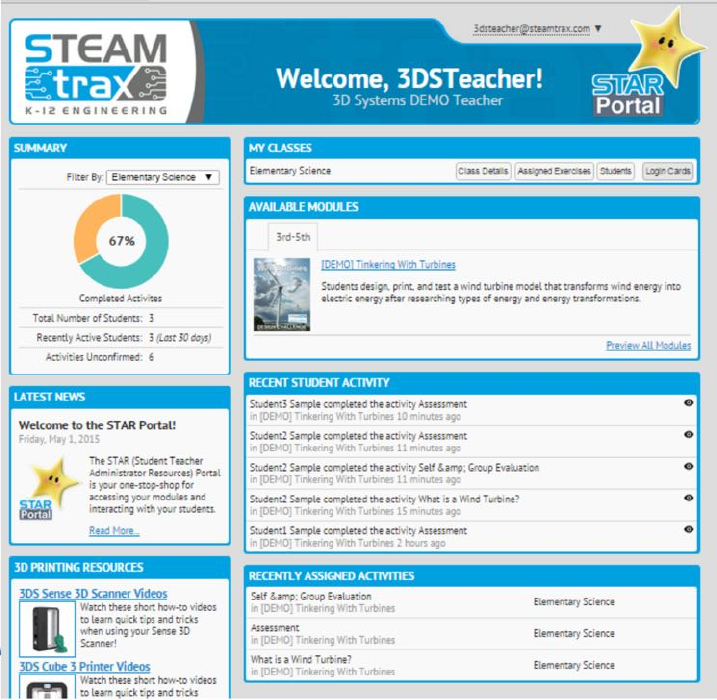
7.1.1 STEAMtrax Star Portal teacher dashboard
The teacher dashboard includes nine panels:
1. SUMMARY – A per-class (for cases where a teacher has
more than one class using STEAMtrax) summary of the
percent of activities (assignments) completed, the total num-
ber of students, the number of students recently active (last
30 days), and the number of activities which are uncon-
firmed (not yet checked by the teacher).
2. MY CLASSES – Access to class information including the
CHAPTER 7. STEAMTRAX CURRICULUM 193
name of the class, the students in the class and the as-
signments for each student, the assigned exercises for the
class and the total number of students who have been as-
signed/completed/confirmed for each such assignment, and
the login data for each student. (The class and student data
is customized for each teacher by STEAMtrax; see Section
7.2 for details on this process.)
3. LATEST NEWS – STEAMtrax news for teachers.
4. 3D PRINTING RESOURCES – How-to videos on print-
ers, software, and scanners, as well as other helpful tips for
teachers.
5. ENGINEERS TODAY – News on engineering. (Student
dashboards also have this panel.)
6. 3D PRINTING ZONE – 3D printing news, resources, and
interesting .stl files. (Student dashboards also have this
panel.)
7. RECENT STUDENT ACTIVITY – A running list of re-
cent student activity. The teacher can review a student
activity/assignment submission by clicking a preview icon
next to the submission item. Within the preview, the
teacher can decide to “Confirm Assignment Completion”
or “Reassign to Student”. This is a way for the teacher
to track which assignments he or she has reviewed, and to
provide feedback to students by reassigning when the sub-
mission needs re-working.
8. RECENTLY ASSIGNED ACTIVITIES – A running list of
the class assignments for this class.

CHAPTER 7. STEAMTRAX CURRICULUM 194
9. AVAILABLE MODULES – Teacher-level access to mod-
ules. All purchased modules, organized by grade band, can
be accessed from this panel.
7.1.2 STEAMtrax module teacher view
Every engineering module is organized with four sections.
Within each section, material visible only to teachers is labelled
in green on the dashboard, while material also visible to students
is labelled in red on the dashboard.
1. Module Preparation – Pre-Lesson Instructions. Teacher-
CHAPTER 7. STEAMTRAX CURRICULUM 195
visible materials under Module Preparation typically in-
clude:
(a) Welcome – Outlines for the teacher the four key sec-
tions of the module.
(b) Targeted concepts & skills – Outlines for the teacher
how the module aligns to standards.
(c) Teacher background – Introduction for the teacher to
background science and math concepts that will be
taught in the module.
(d) Setup-Up and Management – Guidance to teachers on
what should be printed out ahead of time, and how to
set-up the learning stations.
(e) Materials Needed – A complete list for the teacher of
all the hands-on materials needed to run the module.
(Note that pre-packaged, hands-on, Engineering Kits of
everything needed may optionally be purchased along
with the STEAMtrax module.)
(f) Parent letter – A letter, customized for each module,
for the teacher to send home with students. (The stu-
dent module view also has access to this letter.)
(Note that in print delivery format, any setup and man-
agement instructions, list of materials needed, background
concepts for the teacher, targeted concepts and skills out-
lining how the module aligns to standards, and the parent
letter are all collected into a “Teacher Guide”.)
2. Classroom Guide – A Facilitation Guide to orient the teacher
and guide the teacher through the module, a Classroom
CHAPTER 7. STEAMTRAX CURRICULUM 196
Guide to use in the classroom, and 3D printing file(s) and
instructions as a starting point for use and reference.
(a) Facilitation Guide – A detailed resource including pac-
ing, facilitation questions, objectives, and overall step-
by-step guidance to run the module. It is recommended
that the teacher print this out ahead of time to under-
stand the module flow, and jot down any notes.
(b) Classroom Guide – A detailed resource for teachers to
use in the classroom. Every module follows the En-
gineering Design Process, and the classroom guide re-
source is built to guide teachers and students through
the process. The Class Guide EDP may include pop-up
slides for the teacher to project on a screen or electronic
white board to guide students through the process of
the module.
(c) 3D Printing Files – Sample .stl file(s) and step-by-
step CAD instructions for the teacher and students to
use and reference. (The student module view also has
access to this section.)
3. Student Activities – Activities for the students, and down-
loadable materials.
(a) Activities may include readings, videos to watch, as-
signments to print 3D objects, etc.
(b) Lesson downloads always includes at a minimum a Stu-
dent Notebook,inwhichstudentsaretorecordtheir
observations and conclusions.
4. Student Assessments – Evaluation form, rubric, and an as-
CHAPTER 7. STEAMTRAX CURRICULUM 197
sessment, as well as a (teacher-only visible) assessment key.
(a) Evaluation Rubric – Downloadable, and provided as an
example rubric for students, as well as the teacher, to
reference. (The student module view has access to this
also.)
(b) Self & Group Evaluation – Students also have a copy
of this form in their Student Notebooks. The teacher
can choose whether to have students fill it out in their
Student Notebooks, or whether (if the teacher clicks an
“Assign to Students” button on this evaluation section)
to have it also show up in the students’ Star Portal as
an assignment to be completed online.
(c) Assessment – The assessment is not visible to students
until the teacher assigns it (by clicking an “Assign to
Students” button); at that point, once assigned, it be-
comes visible to the students.
(d) Teacher Answer Key – Assessment answer key for teacher
reference.
CHAPTER 7. STEAMTRAX CURRICULUM 198
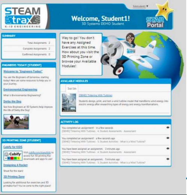
7.1.3 STEAMtrax Star Portal student dashboard
The student dashboard includes five main panels:
1. SUMMARY – Total assignments, Complete assignments,
Confirmed assignments. (Confirmed assignments are those
that the teacher has reviewed and checked o↵.)
2. ACTIVITY LOG – A record of what the student has been
CHAPTER 7. STEAMTRAX CURRICULUM 199
assigned, when it was assigned, and (if completed) when it
was completed.
3. ENGINEERS TODAY – Updates on engineering.
4. 3D PRINTING ZONE – 3D printing news, resources, and
interesting .stl files.
5. AVAILABLE MODULES – Student-level access to mod-
ules.
In addition, for K-8 students a “Stacy STEAMtrax” char-
acter icon displays a blurb guiding the student to any new as-
signment or confirming to the student that all assignments have
been completed.
7.1.4 STEAMtrax module student view
Just like teachers, students can access a module by clicking on
the module link under the AVAILABLE MODULES panel in
their student dashboard; (see Section ??). And (again like teach-
ers) the students see four main sections in each module in the
student module view. However, students do not see also the
teacher-only visible background and guidance material within
the sections. Instead, in the student module view, what appears
may typically be something like:
1. Module Preparation
(a) Parent letter
2. Classroom Guide
(a) 3D Printing Files
CHAPTER 7. STEAMTRAX CURRICULUM 200
3. Student Activitities
(a) Activities
(b) Lesson downloads – Includes at a minimum a Student
Notebook.
4. Student Assessments
(a) Evaluation Rubric
(b) Self & Group Evaluation
(c) Assessment – Only becomes visible to students once
the teacher assigns it.
7.2 STEAMtrax user import
STEAMtrax is accessed through its Star Portal at
http://build.steamtrax.com
So that STEAMtrax will be ready to use the first time a
teacher logs in at that portal, STEAMtrax has a process for
entering general information regarding the teacher and class that
will be using STEAMtrax. The instructions for importing the
teacher and general class data may be found at:
https://polar3d.freshdesk.com/support/solutions/articles/9000096273-
user-import-instructions
Please contact Polar 3D if you have any questions or difficul-
ties entering the class data.
CHAPTER 7. STEAMTRAX CURRICULUM 201
7.3 STEAMtrax user password management
The teacher and each student using STEAMtrax will each have
their own password.
With a busy lesson plan and a short period, there’s nothing
worse than lost class time; retrieving lost student passwords can
be a huge time waster! Because we know that keeping a class on
topic and engaged is the bedrock of classroom management, the
STEAMtrax Star Portal includes a simple mechanism to make
it easy to retrieve lost student passwords and to prevent student
passwords from being lost in the first place:
1. Log in to the teacher’s STEAMtrax portal at
http://build.steamtrax.com
CHAPTER 7. STEAMTRAX CURRICULUM 202
2. Locate the student’s class in the MY CLASSES panel.
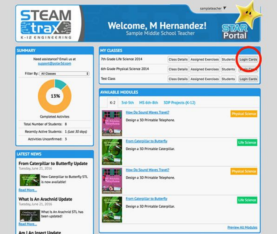
CHAPTER 7. STEAMTRAX CURRICULUM 203
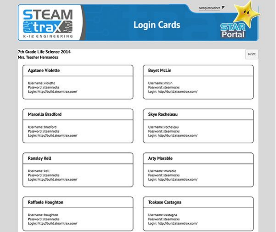
3. Click on the Login Cards button associated with that class.
CHAPTER 7. STEAMTRAX CURRICULUM 204
The screen will then display a list of all students, including
their user names and passwords. This list is updated every
time a student changes his/her password, so you always
have easy access to the most up-to-date login information
for each and every one of your students.
4. Note the Print button in the upper righthand corner of
the Login Cards screen. By printing this Login Cards page
on a sheet of 8.5 X 11 Avery label paper, you can create
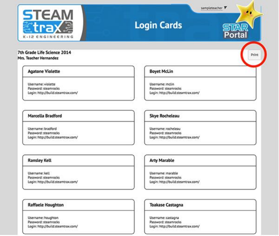
CHAPTER 7. STEAMTRAX CURRICULUM 205
an adhesive label for each student that can be attached
to the inside of a binder, folder or adhered to the back of
the student’s STEAMtrax Student Notebook. This allows
the students to easily manage his/her own password by
referring to this label.
For additional discussion, see:
Polar 3D support: My student forgot his/her password!
Chapter 8
Operational tips
1. Good adhesion of objects to the build plate improves build
quality, and reduces the frustration of objects coming loose
partway through a build.
2. Good positioning of object(s) on the build plate can im-
prove speed and quality of prints.
3. Know the characteristics of your filament.
4. Perform periodic maintenance on the printer, as discussed
in Chapter 10.
8.1 Positioning objects
Thoughtful positioning of your object on the build plate can
improve print speed and quality:
1. For faster print completion, position objects towards the
edge of the build plate.
206
CHAPTER 8. OPERATIONAL TIPS 207
2. Print multiple small objects at once; this can actually im-
prove the quality of objects (as well as production speed).
3. Avoid straight-line extrusion runs through the center of the
build plate.
8.1.1 Position objects towards the edge of the build
plate
In consequence of the Polar3D printer’s underlying polar coor-
dinates architecture, note that objects may print faster if you
position them towards the edge of the build plate, rather than
at the center. Positioning an object towards the edge of the
build plate won’t e↵ect the speed of extrusion; but when the
printer needs to spin the build plate to achieve a non-extrusion
move, the same angular spin results in a longer arc length (faster
movement) towards the edge of the build plate.
8.1.2 Print multiple small objects at once
When printing a small object, especially a small and tall object,
the printer may print so quickly that successive layers are de-
posited while lower layers are still hot and malleable, resulting
in a “smooshed” or “melted” e↵ect on the print: a less than
optimal print outcome.
One approach is to slow down the print, for instance by in-
serting Gcode for a delay after each layer. Another approach is
to point a small fan at the build plate, to speed up the cooling
process, so that even small, quickly-printed layers get cool be-
fore the printer gets to the next layer. A third approach is to
CHAPTER 8. OPERATIONAL TIPS 208
consider printing multiple objects: the time the printer spends
moving to another section of the build plate, and then printing a
layer of another object, is likely to suffice to let the first object’s
layer cool.
See Section 4.6.1 and Section 4.6.1.1 for a discussion of adding
an object or objects to the build plate.
8.1.3 Avoid straight-line extrusion runs through the
center of the build plate
The Polar3D printer’s underlying polar coordinates architec-
ture means that in order to perform a “straight-line” extrusion
through the very center of the build plate,theprintermust
pause extruding when it reaches the center of the build plate
and perform a 180°spin, before resuming printing. This makes
this a point where if your printer’s calibration is less than per-
fect, it may be more apparent here (straight-line extrusion runs
through the center point of the build plate) than anywhere else:
with less than perfect callibration, you might see a jog in the
output, a bit of a blob at the exact center, a slight bend in the
line, etc.
So if the appearance of an exact, smooth, straight line is an
important part of the object you are printing, try to position
the object so that (visible) such straight lines of material don’t
have to go through the exact center of the build plate – or else
be very careful with your callibration.
CHAPTER 8. OPERATIONAL TIPS 209
8.2 Adhesion and adhesion problems
Sometimes during a print an object will come loose from the
build plate, usually resulting in the print being ruined.
The first layer of the print needs to stick to the build plate.
Preparing the build plate properly, to be sticky so that that first
layer adheres, can aid in avoiding this occurrence.
It is also important that the initial layer print at the correct
height above the build plate: just a little “squished” so that it
adheres, not too high so that it doesn’t adhere, nor too low so
that it is overly “squished” or dragged by the print nozzle.
If the printer has just been turned on and heated up, it is
also important that the extruder is consistently emitted melted
plastic during the entire first layer, rather than “burping” and
failing to emit melted filament at spots in the first layer. This
does not tend to be a problem with the Polar3D printer – but if
you do encounter a problem consistently extruding melted fila-
ment when the printer first begins extruding, consider printing
afewskirt loops to establish a smooth flow of filament, before
printing the actual object.
And printing at the proper temperature for your filament is
important for adhesion.
Some objects, however, will need extra assistance for adhe-
sion. In those cases, printing a brim or raft may aid in keeping
the object in place.
CHAPTER 8. OPERATIONAL TIPS 210
8.2.1 Making the build plate sticky
You should ensure that the build plate is a bit “sticky”. What
sort of stickiness works best depends a bit on what type of fil-
ament you are using. The filament that Polar 3D sells is PLA
(PolyLactic Acid) filament, which sticks well to certain brands
of hair spray, to the glue in many common glue sticks, or to
ordinary blue painter’s tape.
Hair spray is particularly quick and easy to apply. Aqua
Net Extra Hold works well; or look for any other hair spray
containing VA/crotonates/vinyl neodecanate copolymer. After
applying a generous layer to a new or freshly cleaned build plate,
you need only lightly “touch up” the hair spray for additional
prints; for a video demonstration, see:
https://www.instagram.com/p/BJBaWwrjCwF/
As the hair spray will tend to build up over time, every so
often, (every few weeks, depending on how heavily used the
printer is), clean the build plate with hot water and paper towels,
and then reapply a fresh generous layer of hair spray.
But if glue sticks are more convenient for your classroom, they
work too, though they may result in an object sticking too well
if a heavy layer is applied – try to apply a very thin, even coat to
the build plate. Any PVA (Polyvinyl acetate) based glue stick,
including Elmer’s washable glue sticks/Purple Disappearing glue
sticks, or Scotch glue sticks, should work.
A layer of blue painter’s tape on the build surface is another
way to achieve an adhesive surface, though applying it is liable
to take a bit more time. (Also, sometimes an object will start
CHAPTER 8. OPERATIONAL TIPS 211
pulling the tape o↵, at which point the rest of the build will
likely be warped.) Lay down a uniform layer of tape, with no
gaps and no overlapping of the edges of the strips of tape. The
painter’s tape will need to be replaced when its surface becomes
less adhesive, typically after about five to ten prints at the same
location.
For ABS filament, the above build plate preparation approaches
(hair spray, glue stick, or painter’s tape) work; in addition, ABS
will also stick to PEI sheets, PET sheets, or Kapton tape, or
the build plate may be spread with “ABS juice” – a slurry made
from ABS and acetone (which dissolves ABS).
8.2.2 First layer height calibration
For proper adhesion, as well as a smooth base layer, it is im-
portant that the initial layer of the object print at the correct
height above the build plate: just a little “smooshed” so that it
adheres. When the Z height of the first layer is well-calibrated,
the lines of the first layer should be slightly touching. If there
are gaps in the first layer between the lines of material, then
the Z height is too high; if the lines of material are overlap-
ping and aren’t forming a smooth surface (or material is getting
dragged or smeared by the print nozzle), then the Z height is
too low.
To adjust the calibration, connect to your printer’s local
web interface (e.g.,connecttoyourprinter’slocalIPaddress–
see Chapter 5), select “Calibration”, and click on “Z offset
down”. This action will lower the Z home by 0.05mm (about 1/2
the thickness of a sheet of paper). Continue to lower the gantry
CHAPTER 8. OPERATIONAL TIPS 212
until the tip of the extruder is just touching the build plate.
When you are at the correct height, click the “Just Right”
button.
Also, though unlikely: check that the build plate is maintain-
ing a consistent height from the extruder nozzle over the build
plate shuttle’s range of motion (since if the height isn’t consis-
tent, that first layer may not be getting consistent “smooshing”).
Check the Z height with the extruder at the middle of the build
plate; then slide the build plate shuttle forward so that the ex-
truder is at the edge of the build plate and confirm that the Z
height hasn’t changed. If the Z height is changing from middle
to edge of build plate, then see Section 10.6 for a discussion of
checking and correcting build plate shuttle alignment.
8.2.3 First layer print speed and thickness
“PRINT SETTINGS” (in the Polar Cloud, specified under “Object”,
the object in question, “3D Print”) has a couple of settings that
may a↵ect the printing of the first layer and therefore its ad-
hesion properties. See in particular the “ADVANCED” setting of
“Speed”, “First Layer Speed”, and the “ADVANCED” setting of
“Quality”, “Initial Layer Thickness”.
8.2.4 Temperature and adhesion
With PLA filament, if you print at too high of a temperature,
the PLA will curl slightly when it cools along the edges, which
might pull the edges up o↵the build plate over time. If you’re
using Polar 3D filament, we recommend 185°C. PLA filament
CHAPTER 8. OPERATIONAL TIPS 213
from other manufacturers may need to be printed at a slightly
di↵erent temperature; check any information from the manufac-
turer of the filament.
Note that ABS filament is quite prone to curling as it cools,
which is one reason why we don’t recommend ABS filament for
beginners; PLA filament is much more forgiving (if printing at
the proper temperature).
8.2.5 Brims, rafts, and skirts
Sometimes, especially when printing an object with a small foot-
print on the build plate,anextraadhesionfeaturesuchasabrim
may be helpful.
Abrim is extra material, typically only one or two layers tall
and several outlines wide, printed around the perimeter of the
object touching the object, extending outward, to stabilize the
object. A brim tends to be helpful with small or isolated parts
of a model, e.g., hooves of an animal, to aid with adhesion of
the small area of the object to the build plate by extending the
area.
Araft is a few extra layers of material, printed as a horizontal
latticework, extending under the entire object. Besides helping
with adhesion, it can also provide a strong foundation for the
rest of the print. The number of layers in the raft controls
the height (and to some degree the strength) of the raft; the
raft o↵set controls how far beyond the main object the raft will
extend; the raft separation determines the distance between the
raft and the object itself – typical distances range from 0.14–
0.2mm – where you want to aim for a close enough distance to
CHAPTER 8. OPERATIONAL TIPS 214
give adequate adhesion during the build, but not so close that
it becomes very difficult to remove the raft from the object once
the print has finished; the raft infill controls the density of the
interior of the raft, where you want enough material to support
the bottom of your main object but not so much that the raft
is so solid that it bonds too tightly to the bottom of your main
object.
Askirt is an outline of extra material printed surrounding
the perimeter of the object, but not touching it, typically o↵set
3 or 4 millimeters from the object; it is thus similar to a brim
that has been moved farther from the object itself. However,
unlike a brim, sometimes a skirt might be quite tall – even the
height of the object itself – rather than, like a brim, being only
a few layers high. This is because a skirt is sometimes used
to shield the object from drafts; as such, they tend to be used
more with filament such as ABS where uneven cooling can cause
warping.
Including a brim around small or isolated parts of a model
object may aid in adhesion and stability of that portion of the
build. Including a raft under a model object may aid in adhesion
of model objects that have small footprints on the build plate, as
well as adding stability and a solid foundation for the rest of the
build, especially if the overall object is relatively large compared
to its small footprint on the build plate. Building a skirt along
with an object may help establish smooth nozzle flow, or may
be used to shield especially thermal-sensitive filament material
from thermal drafts during the print.
Only brims tend to be of much interest when using PLA
filament, such as that shipped with the Polar3D printer and sold
CHAPTER 8. OPERATIONAL TIPS 215
by Polar 3D. Rafts and skirts, in contrast, may be of interest
with other filament materials, such as ABS.
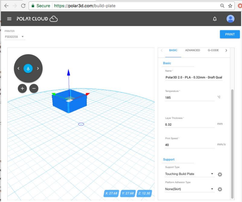
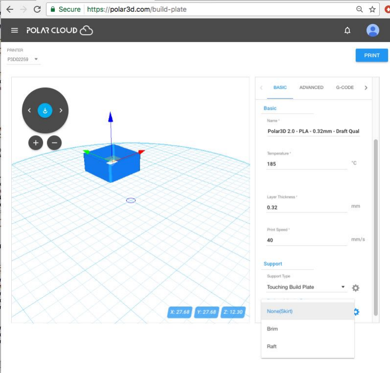
Figure 8.1: Polar Cloud build plate PRINT SETTINGS
The Polar 3D Cloud 2.0 has a feature whereby you can ask
to add a brim, raft, or skirt to your object. Once you have
selected an object and clicked “3D PRINT” to get ready to print
it, then go to “PRINT SETTINGS”, (see Figure 8.1), and under
“BASIC” settings scroll down to Support, (see Figure 8.2). Then
under “Platform Adhesion Type” use the drop-down menu to
select “None(Skirt),“Brim”, or “Raft”, as desired; see Figure
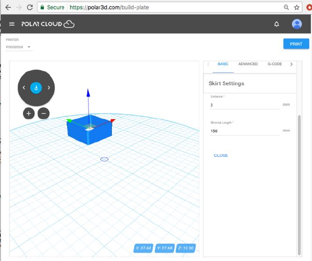
8.3.Thenclickthegearicontoadjusttheparameters(layers,
outlines, raft infill,etc.) as desired; see Figure 8.4.
CHAPTER 8. OPERATIONAL TIPS 216
Figure 8.2: Polar Cloud build plate Support
CHAPTER 8. OPERATIONAL TIPS 217
Figure 8.3: Polar Cloud build plate Platform Adhesion Type
CHAPTER 8. OPERATIONAL TIPS 218
Figure 8.4: Polar Cloud build plate Skirt Settings
8.3 Removing objects from the build plate
Cooling a printed object, still on the build plate, briefly in the
refrigerator or freezer may make it easier to remove from the
build plate. Remove the build plate,withfreshlyprintedobject
still attached, from the 3D printer and place it in the refrigerator
or freezer: four or five minutes in the freezer may suffice.
Aspatulamaybeusefultoaidinremovingobjectsfromthe
build plate.
Note that while an object may be less “stuck” to the build
plate while still slightly warm, delicate or fragile details may
CHAPTER 8. OPERATIONAL TIPS 219
benefit from thoroughly cooling before you attempt to remove
an object.
For some ob jects, printing with a raft may better allow re-
moval from the build plate without damage to the bottom of
the object.
After removing an object, check whether it is time to clean
the build plate and/or apply more hair spray (or other adhesion
aid).
8.4 Filament
If you have a Polar3D printer and have filament from a previous
3D printer, you are in luck! Polar3D does not use proprietary
filament. This means that as long as you have 1.75mm diameter
filament, your Polar3D printer can print it.
Note that we strongly recommend use of PLA filament in the
classroom as it: (1) is easier for beginners, and (2) does not
require ventilation.
Our other suggestion is that when it comes to filament, cheaper
is not always the best choice. An extra cheap roll of filament
may not have the same print quality as the Polar 3D filament,
or other standard brands of filament. For instance, you may
find particles within the filament cause jams in the 3D printer,
making it an annoyance to keep cleaning it out; (see Section
10.3). Or filament whose diameter does not remain consistent
may result in lower quality prints.
Especially if you’re using filament from a supplier other than
CHAPTER 8. OPERATIONAL TIPS 220
Polar 3D, measure precisely the diameter of your filament with
a caliper. And know what temperature is best for your fila-
ment, and be sure to set the printer extruder temperature ac-
cordingly. See Polar Cloud PRINT SETTINGS to adjust for a
di↵erent filament diameter (under “ADVANCED”) or temperature
(under “BASIC”).
8.4.1 Types of filament
Note that while there any many di↵erent and interesting types of
filament, di↵erent types of filament have di↵erent requirements
for printing: know your filament’s characteristics.
Just a sample...
For instance, glow-in-the-dark PLA filament is fun for stu-
dents. But be aware that it is typically: (a) fairly abrasive
on the extruder nozzle – be prepared to replace your extruder
nozzle if you perform much glow-in-the-dark printing, (b) more
expensive than regular PLA,and(c)greenandblueglowe↵ects
are generally more satisfactory than other colors. Some users
recommend that best glow e↵ects result from objects that are
fairly hollow but with thicker walls, so consider slicing objects
using no (or very little) infill while adding a few more shells than
usual.
Similarly, color-changing PLA filament – changing color in
response to temperature or, for some brands, in response to
UV light – can be fun for students. It also tends to be more
expensive than regular PLA, but unlike the glow-in-the-dark
PLA, does not tend to be especially abrasive.
CHAPTER 8. OPERATIONAL TIPS 221
Wood filament (PLA infused with woo d dust/wo od fibers)
results in objects with the look and feel of wood. A number
of di↵erent brands, incorporating di↵erent types of woods, are
available. Note that it’s moderately difficult to work with (as
opposed to plain PLA which is relatively easy): it tends to be
more finicky about print temperature (which typically needs to
be a bit higher than that for Polar 3D PLA), is subject to some
shrinking during printing, and may not adhere as easily as plain
PLA.
Conductive PLA is PLA infused with conductive carbon. It
allows printing low-voltage electronics. It tends to need to print
at a slightly higher temperature than plain PLA, and while it
is considered fairly easy to print, and is not reported to be par-
ticularly abrasive on the extruder nozzle, it is a little harder to
get it to adhere (even to itself); also, it tends to be expensive
compared to regular PLA.
Carbon Fiber PLA is PLA mixed with small, chopped carbon
fibers. It results in strong objects, much stronger than regular
PLA, but is extremely abrasive on the extruder nozzle; expect
to have to replace your extruder nozzle after printing only 550g
(half a regular spool) of carbon fiber PLA .
Metal PLA is PLA combined with fine metallic power, such
as bronze powder, brass powder, copper powder, aluminum pow-
der, or steel powder. Objects 3D printed using metal PLA fil-
ament will look and feel as if they were made of metal, can be
polished like metal, and will be denser (heavier) than regular
plastic objects, hefting more like metal. However, metal PLA
is quite abrasive on the extruder nozzle, especially when the
incorporated metal is a harder metal than the brass of the ex-
CHAPTER 8. OPERATIONAL TIPS 222
truder nozzle. Metal PLA filament is considered quite a difficult
filament to get printing well, so be ready for a challenge!
ABS filament is second only to PLA filament in terms of
popularity for general 3D printer use. However, it is not usually
recommended for use in the classroom, due to the intense fumes
it generates during printing which can be dangerous for those
with breathing difficulties; when printing ABS, the 3D printer
must be placed in a well-ventilated area, and you must avoid
breathing in the fumes when it is in use. Also, ABS shrinks
while cooling, so it is very prone to curling, and pulling up from
the build plate. Due to ABS’s thermal issues, it prints best on
printers that incorporate both a heated build plate (to lessen
the temperature di↵erential between the bottom and top of the
object while printing) and an enclosure around the print area
(to lessen the e↵ect of cooling drafts); neither feature is part of
the Polar3D printer. However, by extra attention to issues of
adhesion and thermal insulation, it is possible to print ABS on
a Polar3D printer: use of Elmer’s Xtreme glue stick on the build
plate (to glue down the object even as it attempts to cool and
shrink) and adding a tall skirt around the main object (to shield
it from drafts) are techniques that can be used.
PET (PolyEthylene Terephthalate) filament and PETG (a
blend of PET with Glycerol) filament are very versatile, reason-
ably easy to work with, newer filaments, with PETG being a
version better adapted for 3D printing. However, PETG does
tend to be more expensive than regular PLA.
There are many more types of filament, with new kinds con-
tinuing to come out. While some types produce fumes requiring
ventilation (thus being less suitable for the classroom), or need
CHAPTER 8. OPERATIONAL TIPS 223
or benefit from a heated build plate (not a feature of the Po-
lar3D printer), or are distinctly more challenging to use than
regular PLA, and exotic types tend to be more expensive, still
other types may be of interest to you.
For some further discussion of these and additional filament
types, see:
Polar 3D youtube video: WWBD – The Di↵erent Types of
Filaments
8.4.2 Loading and unloading (and changing) filament
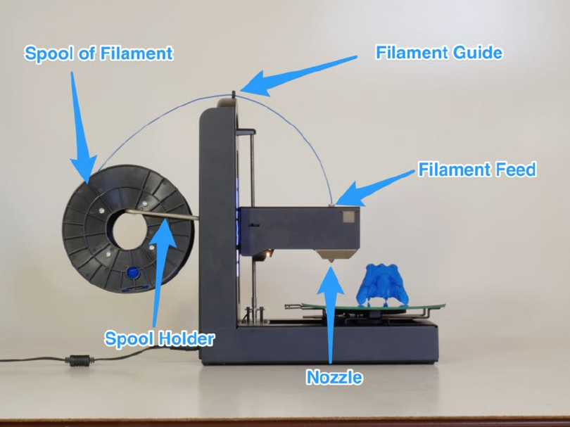
Figure 8.5: Loading filament onto the Polar3D printer
CHAPTER 8. OPERATIONAL TIPS 224
The Polar 3D support site has detailed discussions of loading
and unloading filament on Polar3D printers.
For Polar3D printers with serial numbers P3D02150 and higher,
see:
Polar 3D support document “Loading and Unloading Fila-
ment”
For Polar3D printers with serial numbers P3D02000 -P3D02150,
see:
Polar 3D support document “Loading and Unloading Fila-
ment”
For Polar3D printers with serial numbers P3D00000 -P3D02000,
see:
Polar 3D support document “Loading and Unloading Fila-
ment”
8.4.2.1 Loading filament
Refer to Figure B.1 and especially to Figure 8.5.
1. Take the spool of filament and hook it onto the spool holder.
2. Find the end of the string of filament.
3. If the end of the string of filament is blobby or thin (some-
thing to check if this spool has been previously used, so that
the filament end got a bit melted previously) or kinked (e.g.,
from being pinched in the spool holder), consider snipping
the end o↵– perhaps snip an inch or two o↵– so that you
have a “clean” end to feed into the printer.

CHAPTER 8. OPERATIONAL TIPS 225
4. Feed the filament through the filament guide (the hole at
the top of the Polar3D printer). (Having the filament prop-
erly guided keeps the filament from flopping wildly from the
spool to the print head.)
5. Stick the end of the filament into the feed hole at the top of
the print head.The“feel”ofthistakesabitofgettingused
to: when sticking the filament into the feed, you must push
past some initial resistance: you must push the filament in
far enough to engage with the filament drive gear inside the
print head.
6. If you want to check whether the filament is all the way in,
raise the temperature of the printer to 180°C,1and slowly
hand feed the filament through. Seeing a string of molten
plastic get extruded tells you you’re ready to print!
8.4.2.2 Unloading filament
If the filament is still warm, you should be able to simply pull
the filament straight up and out of the print head.
If the filament is stuck, raise the extruder temperature to
200°C.2Once the filament has softened, you should now be able
to pull the filament straight up out of the print head.
1To set the temperature of the printer, you may use the Polar Cloud printer dash-
board’s temperature dial. Alternatively, you may use the “Controls”screenof the printer
local web interface. If you are using a direct cable connection to the printer and Repetier-
Host to control the printer, under Repetier-Host’s “Your Printer”, use the controls on
the “Manual Control” screen to set the extruder temperature.
2Printer extruder temperature can be controlled at the Polar Cloud printer dashboard’s
temperature dial or at the printer local web interface’s “Controls”screen.Ifusinga
direct cable connection with Repetier-Host to control the printer, under Repetier-Host’s
“Your Printer”, use the controls on the “Manual Control”screentosettheextruder
temperature.
Chapter 9
Updating the printer
Occasionally, an update to the printer firmware will be available.
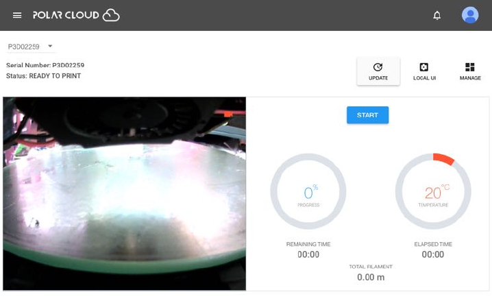
When an update is available, you will see an update button
visible in three locations:
Figure 9.1: Polar Cloud printer dashboard UPDATE button
226
CHAPTER 9. UPDATING THE PRINTER 227
1. On the printer dashboard screen within the Polar Cloud;
Figure 9.1.
2. On the printer manage screen within the Polar Cloud; Fig-
ure 9.2.
Figure 9.2: Polar Cloud printer management screen UPDATE button
3. On the printer’s local web interface; Figure 9.3.
Figure 9.3: Printer local web interface shows Update tab
CHAPTER 9. UPDATING THE PRINTER 228
Clicking the UPDATE button or Update tab in any of these
respective locations will cause the update to be performed.
Alternatively, you can force an update as follows. From a
device (computer, tablet, phone) on your local network, open a
browser window and go to the location:
http://localip /update
where localip is your printer’s local IP address1.
Figure 9.4: Printer update description and confirmation screen
1If you need a reminder of just what your printer’s local IP address is, note that from
within the Polar Cloud, selecting the LOCAL UI tab while viewing a printer dashboard
screen will show you what the Polar Cloud believes to be the printer’s IP address.

CHAPTER 9. UPDATING THE PRINTER 229
Whichever of the three approaches above you use to request
an update, you will be presented with a screen describing the
update which asks you to confirm that you truly wish to update
the printer; an example is shown in Figure 9.4.Click‘Confirm”
to perform the update.
Note that when the printer is performing an update, the LED
lights along the left-hand side of the printer will go through a
color change: the LED lights towards the bottom (3D) will turn
green, POLAR3D , and then the green color will gradually move
up until all the lights are green, POLAR3D , indicating that
the update is complete, before the lights return to their normal
colors (blue over white, POLAR3D ,foraprinterconnectedto
the Polar Cloud).
Chapter 10
Printer maintenance
The Polar3D printer’s polar coordinates-based design means a
simpler machine with fewer moving parts, so fewer maintenance
issues. But as with any machine, there are a few parts that
benefit from some occasional maintenance attention.
10.1 Cleaning your build plate
Something you will need to do fairly regularly is to clean your
build plate.
Remove the build plate from the printer, and wash it with
warm water. If bits of filament are still a bit stuck, rub it lightly
with a fingernail or green scrubber (but do not scrub hard).
Then dry the build plate thoroughly, both top and bottom, be-
fore replacing it on the printer.
For a video demonstration, see:
Polar 3D youtube video: WWBD – Cleaning your Build
230
CHAPTER 10. PRINTER MAINTENANCE 231
Plate
10.2 Lubrication
There are five spots which can benefit from occasional lubrica-
tion: the bottom of the threaded Zrod, and around the bush-
ings on each of the four steel rods (two rods for the build plate
shuttle, and two rods for the gantry); see Figure B.1.Werecom-
mend Tri-Flow lubricant (often used on bicycle chains), which
is a “dry” lubricant. Put a drop of the lubricant at the bottom
of the threaded Z rod, and a drop both in front of and behind
each bushing on each rod.
In addition, if you are hearing any squeaking from the printer,
you may wish to apply a drop of lubricant at the top of the
threaded Zrod, and on the drive pinion.
For a video demonstration see:
Polar 3D youtube video: WWBD – Care and Maintenance
10.3 Clean filament drive gear
Over time, small particles of filament may start clogging up the
filament drive gear in the print head.Afilamentjaminthe
nozzle, or low quality (flaky) filament, or frequent changes of
filament (pushing filament in or pulling it out) may accelerate
this. So occasionally you should remove the block from over the
filament drive gear, clear out any accumulated filament dust or
particles, and reinstall the block.
CHAPTER 10. PRINTER MAINTENANCE 232
For a video demonstration, see:
Polar 3D youtube video: WWBD – How to Unclog a Nozzle
and Clear a Leaky Nozzle
10.4 Replace the nozzle on the extruder
Every so often, sooner if you print with abrasive filaments (see
Section 8.4), or not for a long while if you stick with regular PLA
filament, you may need to replace the extruder nozzle.
Polar 3D support solutions: How do I replace the nozzle on
the extruder of my Polar 3D printer?
10.5 Replace a corrupted SD card
SD cards are fragile, and relatively easily corrupted by static dis-
charges, or sudden power failures. So while it’s rare, sometimes
unfortunately an SD card will need replacing. Please contact
Polar 3D support if you need a new SD card.
If you have had an SD card fail, and now have a new SD card
from Polar 3D to install, for directions on replacing the SD card
see:
Polar 3D support solutions: How to replace the SD card
or
Polar 3D support solutions: Replacing the SD card
CHAPTER 10. PRINTER MAINTENANCE 233
10.6 Printer calibration
One of the advantages of the Polar3D printer’s underlying polar
coordinates architecture, and minimal number of moving parts,
is that the Polar3D printer doesn’t tend to require frequent cal-
ibration. However, occasionally you may want to check and
adjust its calibration.
There are two general types of calibration: (1) the zheight
of the extruder,and(2)theconsistentlevelnessofthebuild
plate.
1. If the zheight of the extruder is slightly high, the first print
layer (first layer of material extruded) may only be lightly
touching the build plate, instead of being “smooshed” so
that it adheres to the build plate. If the zheight is too
low, filament either may not be able to come out at all, or
may come out too “smooshed” and actually flattened.
To calibrate the zheight of the extruder, from within the
Polar Cloud, click on the printer, and then click on the set-
tings (dial icon); or when communicating directly with the
printer, from your device (computer/tablet/phone), con-
nect to the printer’s local IP. At this point you should be
seeing the printer’s local interface:
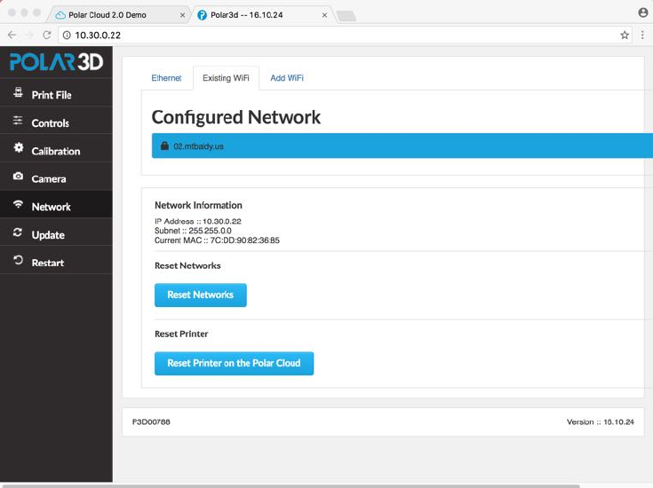
CHAPTER 10. PRINTER MAINTENANCE 234
Select “Calibration” from the stacked tabs on the left,
and click “Z offset down or “Z offset up”, as desired.
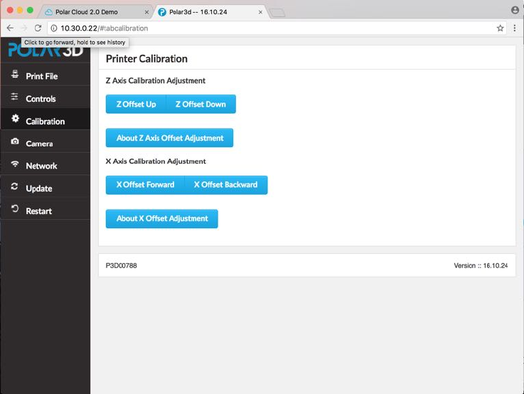
CHAPTER 10. PRINTER MAINTENANCE 235
Each click will lower (or raise) the zhome of the print head
(and hence the extruder)by0.05 millimeters (about 1/2the
thickness of a sheet of paper). Adjust the zheight until the
tip of the extruder is just touching the build plate. When
you are at the correct height, select the “Just Right” but-
ton.
2. The build plate, when sliding forward or back, should re-
main at a consistent height relative to the extruder tip.
Check the zheight with the extruder at the middle of the
build plate; then slide the build plate forward so that the
extruder is at the edge of the build plate and confirm that
the zheight hasn’t changed. If the zheight is changing
from middle to edge of build plate, then:
CHAPTER 10. PRINTER MAINTENANCE 236
(a) The build plate shuttle arms in the back of the printer
(near the Zrod)maybebentdownwards. Pushthese
arms up gently until the extruder nozzle stays at the
same height across the entire radius of the build plate.
(b) The pads that the build plate mirror rests upon may
be slightly o↵. This is normally checked at our factory
when the printer is assembled, but something might
have happened to throw o↵this alignment after leaving
the factory, so it is worth checking to confirm that the
mirror is still properly aligned.

Chapter 11
Troubleshooting
The Polar3D support website has a number of articles and videos
discussing commonly encountered issues. You can also open a
support ticket at that site.
11.1 Printer LED lights
In addition to the small, white lights around the camera under-
neath the print head which are the very first lights to turn on
when the printer is plugged in, the Polar3D printer has LED
lights running vertically on the left hand side, with “POLAR”
showing in blue when the printer is turned on (plugged in), and
with the color of “3D” being an indication of the state of the
printer.
A summary of the meaning of the LED lights on these Po-
lar3D printer is:
1. POLAR3D (BLUE over BLUE): The printer has finished
turning on, but is not connected to a network, and has
237

CHAPTER 11. TROUBLESHOOTING 238
stood up its own wireless network.
2. POLAR3D (BLUE over RED): The printer has been con-
figured to connect to a network, but that network has not
yet, or could not, be found. (The LED lights will only re-
main BLUE over RED for a short time: then the lights
will either return to BLUE over BLUE if the network could
not be found, or progress to BLUE over YELLOW if the
network is found.)
3. POLAR3D (BLUE over YELLOW): The printer found a
network to which it could connect, but the printer has not
connected.
4. POLAR3D (BLUE over WHITE): The printer is connected
through the local network and the Internet to the Polar
Cloud.
5. POLAR3D (BLUE over GREEN): The printer has begun
an update.1
6. POLAR3D (BLUE over GREEN): The printer is partway
through an update.
7. POLAR3D (GREEN): The printer has just completed an
update. (The LED lights will only remain solid GREEN
for a short time; then the LED lights will return to their
prior color(s), e.g., BLUE over WHITE if the printer is
connected to the Polar Cloud.)
See also the Polar3D support discussion: Polar3D Support:
What do the di↵erent LED lights mean?
1The green color will move gradually upwards in the letters, until all the LED lights
are green as the update completes, after which the LED lights will return to their normal
color from before the update.
CHAPTER 11. TROUBLESHOOTING 239
And the Polar3D video:
Youtube Polar3D channel: WWBD - LED Light Explained
11.2 Clogged or leaky nozzle
See:
Polar 3D youtube video: WWBD – How to Unclog a Nozzle
and Clear a Leaky Nozzle
11.3 Flaws in printed objects
1. If an object appears warped due to coming partially or fully
loose from the build plate during the print, take steps to
improve adhesion; see Section 8.2 for some ideas.
2. If objects are printing with rough surfaces, or with lay-
ers that don’t seem fully stuck together, so that the ob-
ject can pull apart, the temperature of the extruder may
have been too low; try increasing the temperature by 5°C
and try again. In particular, if printing through the Po-
lar Cloud, under “PRINT SETTINGS”, “BASIC”, adjust the
“Temperature”.
3. If individual layers, and especially the top layer, look bad,
another possibility besides too low a temperature (men-
tioned above in item 2), is that the filament is not feeding
smoothly and hence not extruding smoothly. Make sure
that the spool of filament is feeding easily and smoothly,
CHAPTER 11. TROUBLESHOOTING 240
(see Figure 2.1), and consider cleaning the filament drive
gear, (see Section 11.2).
4. If strings of unintended extrusion are occurring between
separate parts of your print, then either the temperature
may be a bit too high – try decreasing the temperature
by 5°Candtryagain–orelseyoumayhaveabatchof
filament that is simply rather runny even at lower tem-
peratures – try increasing the retraction a few millimeters
(3 or 4 millimeters). For adjusting the retraction if print-
ing through the Polar Cloud, under ““PRINT SETTINGS”,
“ADVANCED”, “Retraction”, adjust the “Amount” (and per-
haps the “Speed” of the retraction).
5. If corners are messy or blurry or (unintentionally) rounded
rather than sharp, or if there are ripple patterns (corner
ringing) visible on vertical surfaces near direction changes
(corners), the print speed may need to be slowed down. To
slow down the entire print, if printing through the Polar
Cloud, under “PRINT SETTINGS”, “BASIC”, adjust “Print
Speed”.
6. If surfaces have blemishes where the interior print mate-
rial shows through or penetrates (telegraphing), the exte-
rior shell of material may be too thin: modify the print
to have a thicker exterior (use more shells). In partic-
ular, if printing through the Polar Cloud, under “PRINT
SETTINGS”,“ADVANCED”, “Quality”, adjust as relevant the
“Wall Thickness”, “Bottom Layer Thickness”, and/or
“Top Layer Count”.
7. If tall and narrow sections of the print look squished or
melted, the print may be happening so fast, with one layer
CHAPTER 11. TROUBLESHOOTING 241
on top of another, that the material is not cooling suffi-
ciently between the layers. Slow down the print speed,or
point a small fan at the printer, or print multiple objects
(thereby forcing more movement and printing at each layer,
hence forcing more time before returning to print another
layer) to aid in cooling.
8. If you see a jog in the material output, or a slight bend
in what should be a straight line, or a bit of a blob of
material right where an intended straight line of output
material crosses the exact center of the build plate, check
the calibration of the printer and try to reposition your
object so that any visually “important” straight lines are
not positioned exactly across the center of the build plate;
see Section 8.1.3.
9. if the object consistently appears to have skimpy lines of
material being extruded (under-extrusion), or contrarily
consistently appears to have excessive amounts of mate-
rial being extruded (over-extrusion), this may indicate that
the filament you are using has a diameter di↵erent from
what the slicer expected. Measure your filament’s diameter
carefully, and then if appropriate adjust the slicer’s expec-
tation accordingly. In particular, when printing through
the Polar Cloud, under an object’s “3D PRINT” screen’s
“PRINT SETTINGS”, “ADVANCED”, “Filament”, adjust the
“Diameter”.
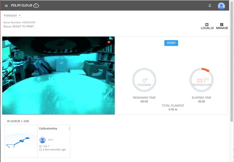
CHAPTER 11. TROUBLESHOOTING 242
11.4 Camera color balance
The camera in the Polar3D printer attempts to perform auto-
matic color balancing. However, occasionally its color balancing
algorithm may yield strange results, where the camera picture
appears to have a strange overall tinge. (In particular, this may
happen if the printer is left on in dark surroundings, such as
overnight; when the lights get brighter, as in the morning, the
color balancing may not readjust properly.) See for instance
Figure 11.1, where the image has a blue cast.
Figure 11.1: Printer camera color balance gets strange
Power-cycling the printer (unplugging it and then plugging
it back in) may reset the camera so that a correct color balance
CHAPTER 11. TROUBLESHOOTING 243
is restored.
Appendix A
Polar3D printer specification
sheet
244
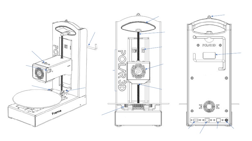
Appendix B
Polar3D printer diagram
X Y Sensor
Shuttle Arm
Build Plate
Filament Loading Hole
Z Threaded
Rod
Serial
Number
Filament Guide
Carrying Handle
Indicating
LED Logo
Fan Grill Holes
Press Fit for
Fan Guard
Build Plate
Gear
0.4mm
Brass Nozzle
USB A
Ethernet
USB B - to PC 12 V
Power In
Raspberry Pi
Indicator
Lights
Spool
Holder
Figure B.1: Polar3D printer diagram
245
Appendix C
Connecting the printer directly
to your device
The Polar3D printer supports direct, non-Internet-enabled, print-
ing; in such modes, the features of the Polar Cloud are not avail-
able, but direct printing may be useful when Internet access is
not available yet you need to print an object. (When Inter-
net access is available, see instead Chapter 1for a discussion of
connecting the printer to the Polar Cloud.)
If this is a brand new Polar3D printer, which you are just
unpacking from its shipping box, begin by performing steps 1
through 4 of Section 1.1; namely:
1. Spray the build plate generously with AquaNet hairspray;
for a video demonstration, see:
https:/www.instagram.com/p/BJBaWwrjCwF/
2. Twist the threaded Zrodclockwise to raise the print head
enough (1” to 2”) to install the build plate.
After you have unpacked the build plate and prepared its
246

APPENDIX C. CONNECTING THE PRINTER DIRECTLY TO YOUR DEVICE247
surface by applying a coat of hair spray (see above), and
raised the print head to make room for installing the build
plate, you are ready to install the build plate on the printer
build plate shuttle.
The bottom center of the build plate has a gear affixed.
Place the build plate so that the center of the gear seats
over the bearing on the build plate shuttle, and the gear
teeth engage with the geared axle of the printer build plate
shuttle.
3. Insert the power cord into the adapter, and insert the adapter
plug into your Polar3D printer. Do not force the adapter
plug; it will not be flush with the printer.
4. Plug in to a power outlet; the Polar3D printer’s LED lights
should turn blue over blue:POLAR3D .
Then there are two ways to connect the printer directly to
your device: wireless (WiFi) – see Section C.1, or via direct USB
cable – see Section C.2.
C.1 Wireless direct connection and printing
For wireless (WiFi) direct connection and printing,youwilluse
the printer’s own hotspot and the printer’s user interface to com-
municate directly with the printer from your device (computer,
tablet, phone), and will be able to print object files stored on
your device.

APPENDIX C. CONNECTING THE PRINTER DIRECTLY TO YOUR DEVICE248
C.1.1 Wireless direct connection
For this type of connection, you will connect to the printer’s
hotspot directly. (Thus this process starts out rather similarly
to configuring the printer to connect via WiFi to a local net-
work, as discussed in Section 1.1, but instead of merely using
the printer’s own hotspot to configure the printer’s connection to
a local network, you will instead stay connected to the printer’s
hotspot and communicate directly with the printer, rather than
using the Polar Cloud interface.)
1. Connect to the printer’s hot spot.
The printer should already be plugged in and all its LED
lights blue:POLAR3D . From your device (computer,
tablet, or phone), select WiFi network. From the list of net-
works, select the P3D network named after your printer’s
serial number, as found on the back of the printer; for ex-
ample, “P3D00526-WIFI”. You will be prompted for a pass-
word, which will be the 8-character serial number consisting
of P3D and five digits: in this example, “P3D00526”.
Note: Your device will not allow itself to be connected to
two WiFi networks simultaneously. If your device is already
connected to a WiFi network, you will need to (temporar-
ily) disconnect from that network and then connect to the
printer hotspot.
2. Connect to the printer.
In your browser (Chrome, Internet Explorer, Safari, etc.)
enter 192.168.0.1 into the navigation bar. (On the printer’s
hotspot, that is, on the private P3D network which is named
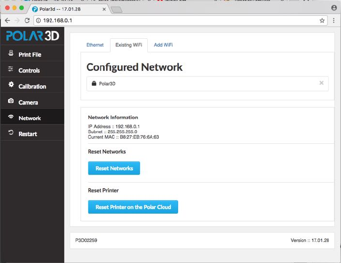
APPENDIX C. CONNECTING THE PRINTER DIRECTLY TO YOUR DEVICE249
Figure C.1: Printer local web interface network status
after your printer’s serial number and which the printer
stood up itself, 192.168.0.1 will be the address of the
printer.) You are now connected to the printer and should
see the printer’s local web interface, as shown in Figure
C.1;(theprinterlocalwebinterfaceisdiscussedindetail
in Chapter 5).
At this stage, in the printer local web interface, note that
there is no blue highlighted network shown under Configured
Network, meaning that the printer is not connected to any
local WiFi, but rather is in HotSpot mode.
APPENDIX C. CONNECTING THE PRINTER DIRECTLY TO YOUR DEVICE250
C.1.2 Wireless direct printing
The steps below describe the full process for uploading and
printing an arbitrary .stl file. (However, note that the Po-
lar3D printer ships with several .stl files, suitable for an initial
test of the printer, already onboard the printer user interface; for
your very first print, you may wish to print one of them rather
than uploading your own file.)
1. On the printer’s user interface, click the Print File button
(top choice in the column on the lefthand side of the win-
dow). This will take you to the Project Details screen,
as shown in Figure C.2.
2. Upload a file to print. (If this is your very first print on
this printer, you may prefer to skip this step, of finding and
uploading an arbitrary .stl file,andinsteadgotostep3
to print one of the files shipped as test print files.)
(a) Under Upload File,selectChoose File.
(b) Find the file, select the file, and click Open.
(c) Click the Upload File button.
3. Select and print the file.
(a) Click the Select file... drop down menu under
Print File (.stl or .gcode).
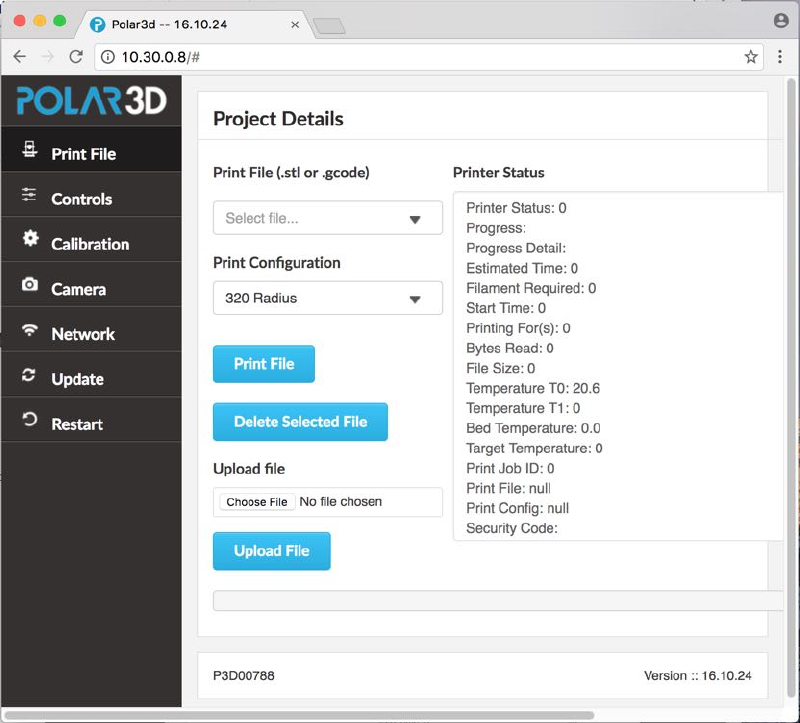
APPENDIX C. CONNECTING THE PRINTER DIRECTLY TO YOUR DEVICE251
Figure C.2: Printer local web interface Project Details screen

APPENDIX C. CONNECTING THE PRINTER DIRECTLY TO YOUR DEVICE252
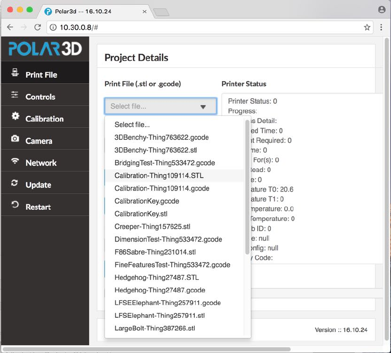

APPENDIX C. CONNECTING THE PRINTER DIRECTLY TO YOUR DEVICE254
4. Click the Print File button.
C.2 Cable direct connection and printing
With the cable direct method of connection and printing,since
you won’t be able to access either the Polar Cloud user interface,
or the Polar3D printer’s own onboard web user interface, you will
need to run third-party printer control software on your device
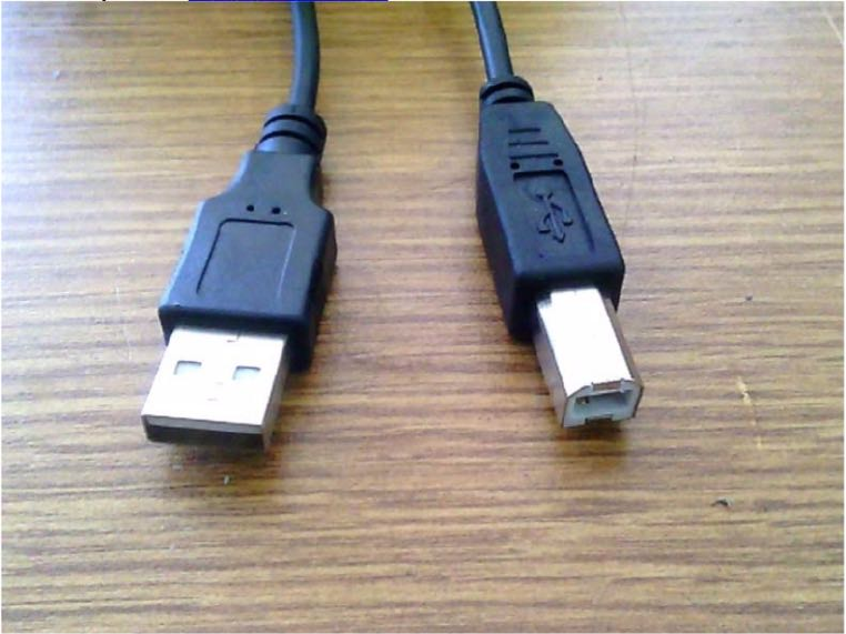
APPENDIX C. CONNECTING THE PRINTER DIRECTLY TO YOUR DEVICE255
(typically your computer) that can control the printer. In par-
ticular, Repetier-Host is free software which can be downloaded
and installed on your computer for this purpose.
You will also need an appropriate cable to connect your printer
with your computer, such as a type-A-male-to-type-B-male USB
cable to connect to your printer.
The proper type of USB cable looks like:
If you do not already have such a USB cable, you may pur-
chase one from Amazon:
https://www.amazon.com/AmazonBasics-USB-2-0-Cable–Male/dp/B00NH11KIK
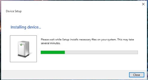
APPENDIX C. CONNECTING THE PRINTER DIRECTLY TO YOUR DEVICE256
C.2.1 Cable direct connection
1. Obtain an appropriate cable, either a type-A-male-to-type-
B-male USB cable of the type described above in Section
C.2,oranEthernetcable.
2. Plug the cable into the printer and into your computer. A
window should pop up that says it is installing drivers. Do
not close that window!
3. Now, download and install Repetier-Host.
4. Start up Repetier-Host. This is what you should see:
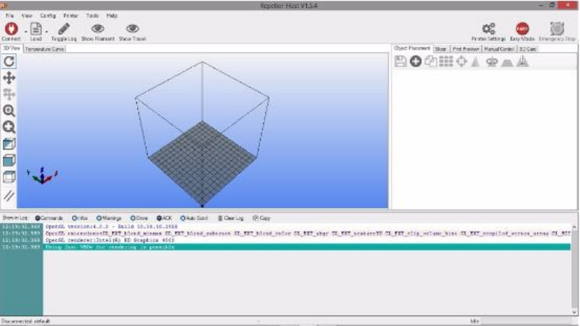
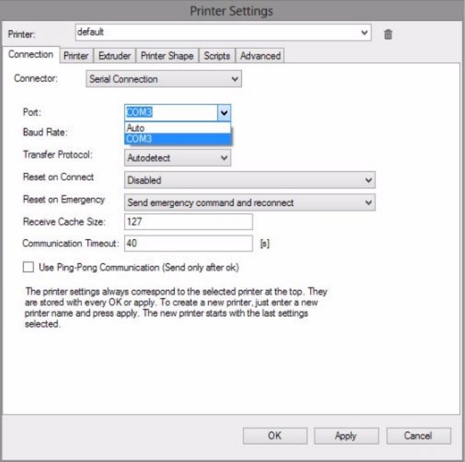
APPENDIX C. CONNECTING THE PRINTER DIRECTLY TO YOUR DEVICE258
First, set the Baud Rate to 115200.
Next, click on the down arrow in the box labelled “Port”
and make a note of the values shown in the dropdown
menu. This will show you what ports you currently have
on the device and will help you determine the port used by
the Polar3D printer. Click “Cancel” to close the Printer
Settings window.
6. Plug your printer back in. Open Printer Settings again.
Select the new value in the drop down menu. In the exam-
ple shown below, that new value is COM13, but the actual
new value may vary.
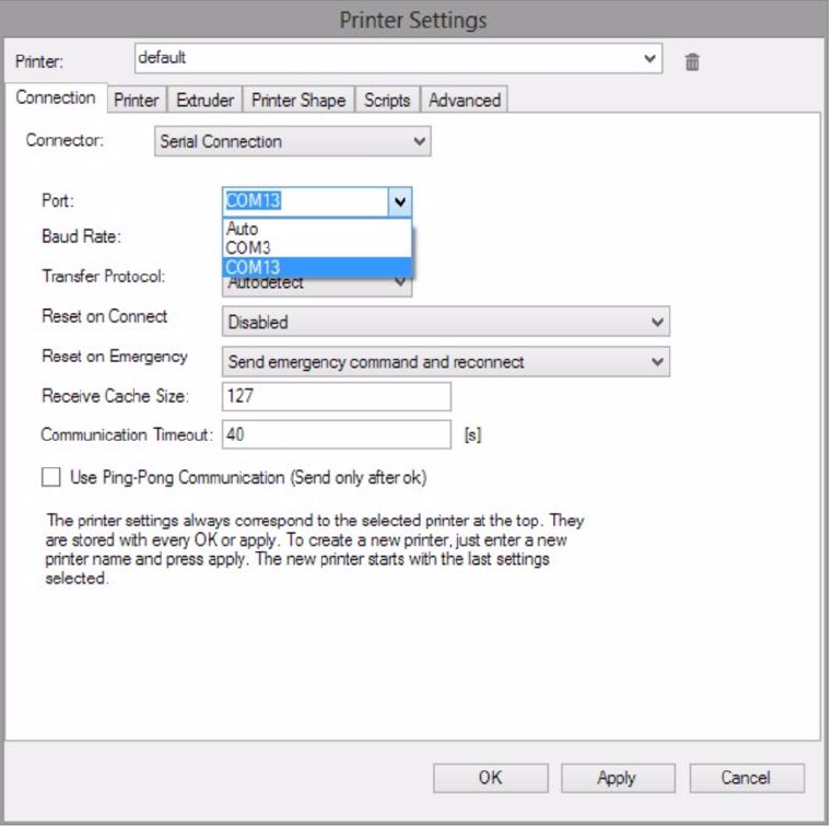
APPENDIX C. CONNECTING THE PRINTER DIRECTLY TO YOUR DEVICE259
Click the “Ok” button to save the changes.
7. Click the red “Connect button (towards the top left of the
Repetier-Host window). If it turns green, that means you
are connected!
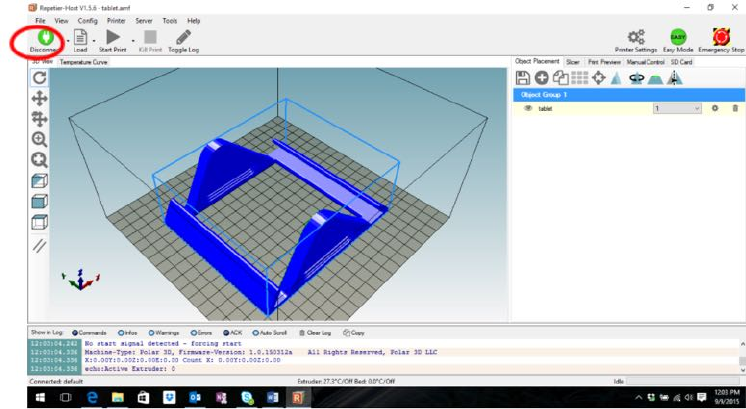
APPENDIX C. CONNECTING THE PRINTER DIRECTLY TO YOUR DEVICE260
8. Now, configure Repetier-Host to work with your Polar3D
printer. Under “Printer Settings”, enter the values shown
in the figure below:
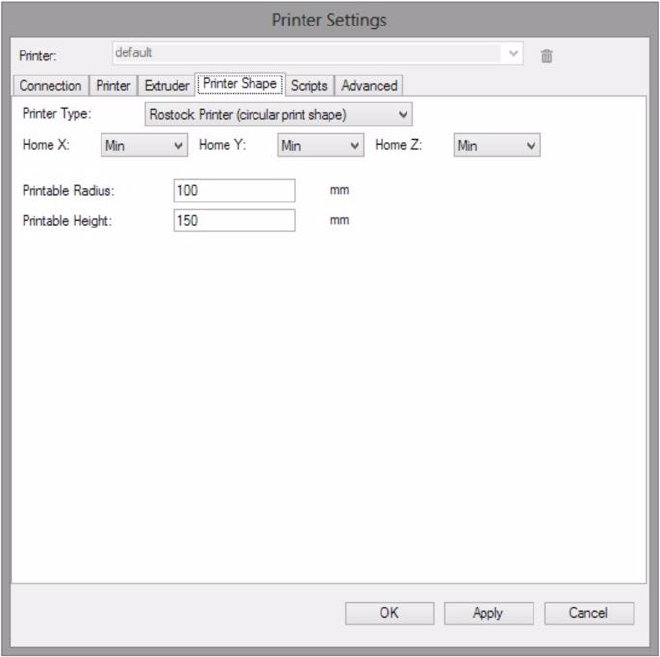
APPENDIX C. CONNECTING THE PRINTER DIRECTLY TO YOUR DEVICE261
Click the “Ok” button to save these settings.
9. Now, configure the CuraEngine slicer settings. (CuraEngine
is the slicer program that converts the 3D model – the .stl
file –toGcode that the printer can read.) Click on the tab
that says “Slicer”, towards the right of the window.
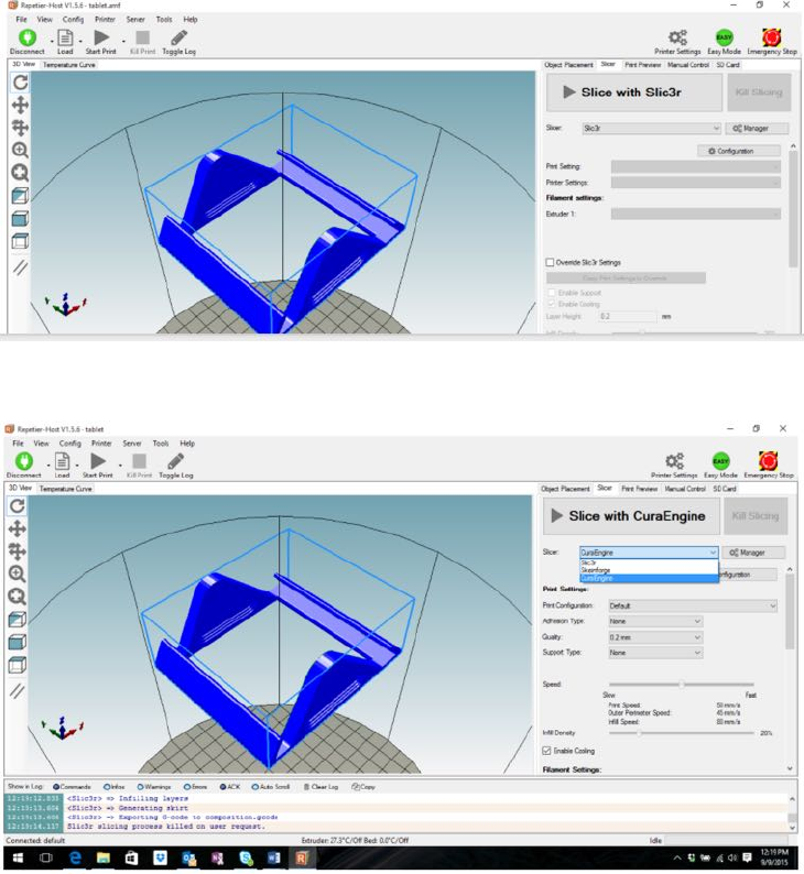
APPENDIX C. CONNECTING THE PRINTER DIRECTLY TO YOUR DEVICE262
10. Make sure that the Slicer choice is set to CuraEngine:
Then click the“Configuration” button:
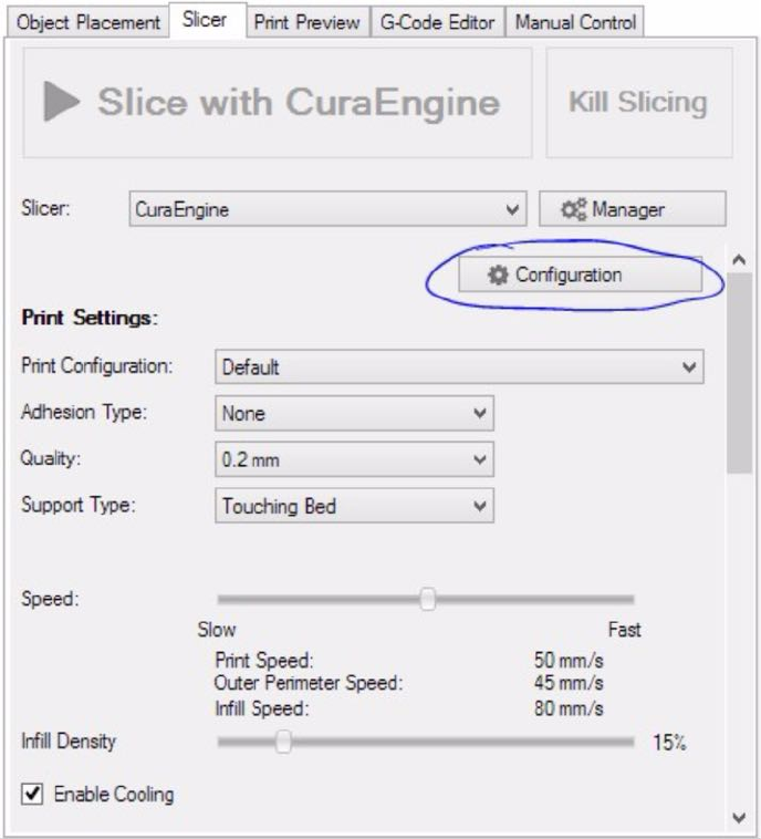
APPENDIX C. CONNECTING THE PRINTER DIRECTLY TO YOUR DEVICE263
11. You will need to download two files from the Polar 3D sup-
port page. The files to download are named “Polar Cura
Settings.rcp”and“Polar PLA Settings.rcf”. They
are available at the Polar 3D support website:
Polar 3D support: Repetier-Host/USB printing
Save the two files to your desktop.
12. Still under the CuraEngine “Configuration” window from
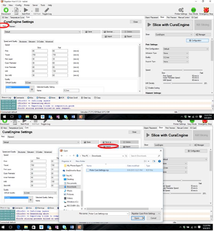
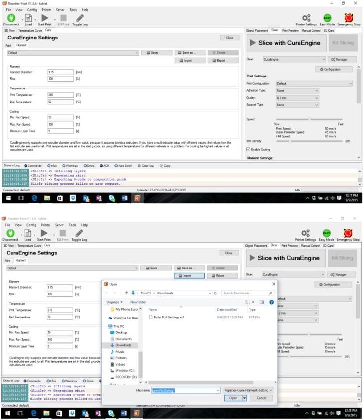
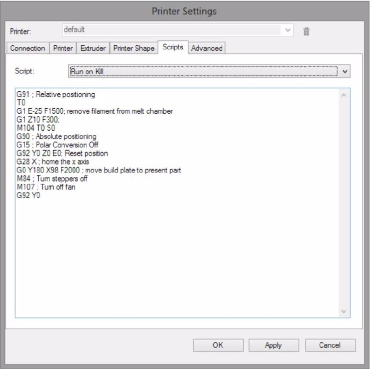
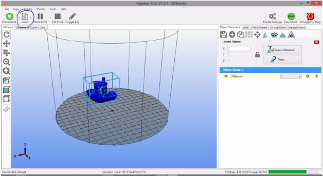
APPENDIX C. CONNECTING THE PRINTER DIRECTLY TO YOUR DEVICE267
C.2.2 Cable direct printing
Once you have connected your printer via USB cable directly
to your computer, and configured the printer controller software
on your computer (e.g., Repetier-Host), as described in Section
C.2.1,youarereadytoprintanobject!
1. Obtain an .stl file to print. (From your computer, you
may want to look for an interesting file on the Polar Cloud,
download it to your computer, and then you will be able to
upload it from your computer to the printer.) But if this is
your first print and you don’t have something else you want
to print, then for your convenience the Polar 3D support
website has a sample .stl file along with the .rcp and
.rcf files you already downloaded during the configuration
in Section C.2.1.GobacktothePolar3Dsupportwebsite
and download the 3DBenchy.stl file to your computer:
Polar 3D support: Repetier-Host/USB printing
2. Use the Repetier-Host “Load” button (towards the upper
left of the Repetier-Host main screen) to load an .stl file:
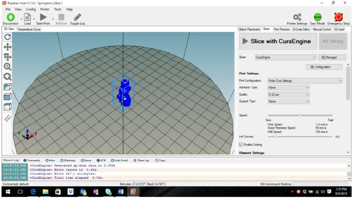
APPENDIX C. CONNECTING THE PRINTER DIRECTLY TO YOUR DEVICE268
3. You may want to change the position of the ob ject on the
build plate. You will generally to position the object so
that it is not at the center of the build plate, and instead is
near the edge of the build plate – this will tend to increase
the speed of the print. (See Section 8.1 for additional dis-
cussion of operational tips regarding positioning objects.)
To move the ob ject, right click on the ob ject and drag it
– for instance, towards the edgeof the build plate. You
can also scale and rotate the object by utilizing the Object
Placement tab on the right of the Repetier-Host screen.
4. Once you are satisfied with the placement of your object,
click the “Slicer” tab, and then click “Slice with CuraEngine”:
5. When the slicing completes, click “Start Print”.
That’s it!
Glossary
3D printer
The Polar3D printer melts plastic filament and deposits
in layers or “slices” to additively build up a solid, three-
dimensional object. More generally, there are a variety of
forms of “3D printing”; see http://www.3dhubs.com/what-
is-3d-printing for an overview.
Plastic filament 3D printers are relatively inexpensive, and
accessible to students. Students may find it interesting to
consider how the sorts of thinking and skills developed using
a plastic filament 3D printer could transfer to alternate
forms of 3D printing.
ABS
ABS (Acrylonitrile-Butadiene Styrene) is an oil-based plas-
tic. If not quite as environmentally friendly as PLA, it is
a bit tougher material, and besides its use as 3D printer
filament, it is also used in making plastic objects for every-
day use, including Lego bricks. 211,213–215,222,See also
filament &PLA
269
Glossary 270
brim
To promote adhesion of the ob ject b eing printed, some-
times an extra ring of material may be printed encircling
the object; this is referred to as a “brim”.
build plate
For 3D printers in general, the build plate is the platform
on which objects are printed. For the Polar3D printer, the
build plate is a round mirror with a toothed gear on the
underside, that meshes with a gear on the build plate shut-
tle. 1,4,208,213,218,230,233,235,239,246,See also
build plate shuttle
build plate shuttle
For the Polar3D printer, the build plate shuttle consists of
the carriage underneath the build plate: the shuttle arms
and pads, and the gear, on which the build plate rests. The
build plate shuttle slides along two support rods (in the x
axis of movement) and rotates (the ✓polar coordinate) the
build plate via its gear. See Figure B.1.4,5,181,182,212,
231,236,247,See also build plate &polar coordinates
CAD
Computer Aided Design is the use of computer systems to
aid in design. CAD output is often in the form of electronic
files; for 3D printing, the industry de-facto standard is .stl
files. 47,49,84,196,See also .stl file
Glossary 271
captive portal
Acaptiveportalisa“landing”webpagethatausermust
view, and at which a user typically must accept prescribed
conditions for access, before access is permitted. Free WiFi
hotspots at business centers, airports, co↵ee shops, etc.,
typically permit access by means of a captive portal, where
after a user accepts the conditions, the MAC address of the
user’s device is permitted access for some period of time. In
the context of Polar3D printers, note that a Polar3D printer
cannot navigate itself through a captive portal; so for a Po-
lar3D printer to get on a local network, the local network
must allow access to the Polar3D printer (perhaps involv-
ing local network configuration to recognize the printer’s
MAC address)without requiring the Polar3D printer to do
an extra step of “viewing” or “agreeing to” some access
agreement. This is the same sort of situation for any hard-
ware device that needs to get on a local network. 8,20,see
MAC address
Cartesian coordinates
Cartesian coordinates are rectilinear coordinates, describ-
ing the position of a point in two-dimensional space via x
and ycoordinates, or in three-dimensional space via x,y,
and zcoordinates. Cartesian coordinates are named after
the 17th century mathematician Ren´e Descartes who devel-
oped them; compare with polar coordinates. See also polar
coordinates
Glossary 272
corner ringing
This is a type of print defect characterized by a ripple pat-
tern which quickly dampens and is seen on the vertical faces
of prints, particularly after a direction change in the sur-
face.
cylindrical coordinates
Cylindrical coordinates are one way of extending polar co-
ordinates to three-dimensional space: cylindrical coordi-
nates use the rand ✓of polar coordinates, plus a zheight.
See polar coordinates
DHCP
DHCP (Dynamic Host Configuration Protocol) is a client/server
protocol that automatically provides an IP host (such as
your 3D printer) with its IP address and other related net-
working parameters such as the IP subnet mask and de-
fault gateway IP address. In the absence of a DHCP server
on a local network, each network device (such as your 3D
printer) will need to have a statically (i.e., manually) as-
signed IP address.
extruder
The extruder, or extruder nozzle, of a 3D printer is the
nozzle at the bottom of the print head, that is extruding
the melted filament. 144,145,176,220,225,232,233,235,
See filament &print head
Glossary 273
filament
In the 3D printing context, filament generally refers to the
plastic filament that the printer melts and prints; PLA and
ABS are two of the most common materials for 3D printer
filament. 37,See also ABS &PLA
Gcode
Gcode, sometimes written as “G-code”, is a numerical con-
trol programming language used to control the operation of
machine tools such as 3D printers. While there is an inter-
national standard for Gcode, the 3D printing community
loosely adheres to it. For example, di↵erent 3D printers ac-
cept di↵erent variations of Gcode. The specific Gcodes pro-
duced by di↵erent slicers and accepted by di↵erent printers
are often not well specified. 139,176,207,261,See also
slicer
infill
Each model to be printed is comprised of an exterior and an
interior. While the exterior is typically printed solid with
no holes or gaps, the interior may range anywhere from
completely empty to completely solid. The plastic printed
in the interior is known as “infill” and its solidity is the
“infill percentage”. For example, 0% infill means the print
is completely hollow and 100% infill means it is fully solid.
Printing time is reduced and plastic is saved by printing
with infill percentages significantly less than 100%. The
amount of infill you should use depends upon the nature of
the piece being printed and its intended usage.
Glossary 274
MAC address
A MAC address (Media Access Control address) of a net-
work device is a unique identifier assigned for network data
layer communications purposes. MAC address are typi-
cally assigned by the manufacturer of a network device, en-
coding the manufacturer’s registered identification number,
and are stored in the device’s read-only memory or other
firmware. Among other uses, a device’s MAC address is a
way of identifying the device for network access purposes.
Mcode
Gcode can contain “miscellaneous” function codes known
as “Mcodes” and which begin with the letter “M”. See
Gcode
MSDS sheet
Material Safety Data Sheets are a widely used system for
cataloging information on chemicals, chemical compounds,
and chemical mixtures – so for instance, the plastic of 3D
printing filament. Note that 3D printing filament, espe-
cially PLA filament, is about as safe as plastic can get; but
for those who need an MSDS document in their environ-
ment, Polar 3D has MSDS sheets available for the printing
filament available from Polar 3D; see the Polar 3D support
document Polar Filament MSDS Sheet.See also filament
&PLA
NGSS
Next Generation Science Standards, released in 2013, were
developed by a consortium of 26 states, the National Sci-
Glossary 275
ence Teachers Association, the American Association for
the Advancement of Science, the National Research Coun-
cil, and the nonprofit organization Achieve. For details, see
http://www.nextgenscience.org.
over-extrusion
When the extruder outputs a surplus of plastic, over-ex-
trusion results. Over and under-extrusion are caused by a
mismatch between the slicer’s expectations and reality: the
slicer expects that when a millimeter of raw filament is fed
into the extruder, a specific volume Veof plastic will then
be extruded — output by the extruder. When the actual
volume of plastic output, Va,exceedsVe,over-extrusionre-
sults; when Vais less than Ve, under-extrusion results.
There are a number of causes of such a mismatch of plastic
extruded, but it generally is the result of the input fila-
ment diameter not matching what the slicer expected, or
the steps per mm for the extruder being incorrect. By care-
fully measuring your filament diameter, and then checking
that that value is properly entered in the slicer – for a
Polar3D printer, this means properly entered under the ob-
ject’s “PRINT SETTINGS”,“ADVANCED”, “Filament”, “Diameter”
– you can generally prevent over- and under-extrusion from
occurring. (But note that poor quality filament whose di-
ameter varies can cause intermittent over-extrusion and
under-extrusion.) 241,See also filament,slicer &under-
extrusion
Glossary 276
PLA
PLA (PolyLactic Acid) is a biodegradable plastic, typically
made from renewable raw materials such as cornstarch or
sugarcane. Besides 3D printing filament, other common
uses are for plastic cups and plastic water bottles. 1,42,
210,212,214,219,220,232,See also filament
polar coordinates
Polar coordinates describe two-dimensional location via ra-
dius, r, and angle, ✓. Compare with Cartesian coordinates,
which instead describe two-dimensional location via xand
ycoordinates. The Polar3D printer uses polar coordinates
at the hardware level, which has several advantages; see the
Polar 3D video “WWBD - Polar is Better”.
Does this mean that you or your students need to use or
understand polar coordinates? No! The Polar3D printer
expects industry-standard .stl files, which describe loca-
tion in the more familiar Cartesian x,y,andzcoordinates;
the Polar3D printer’s firmware automatically converts from
the Cartesian coordinates describing an object to the polar
coordinates (technically, cylindrical coordinates) that the
printer’s hardware uses.
However, if you have students who are learning about polar
coordinates in their math class – see Common Core stan-
dard http://www.corestandards.org/Math/Content/HSN/CN/B/4/
– you may wish to draw such students’ attention to the un-
derlying polar operation of the Polar3D printer, both to
help motivate them as to why one might want to learn
about polar coordinates, and to help them visualize the
Glossary 277
relationship between polar coordinates and Cartesian coor-
dinates.
Also, a couple of printer operational tips will be more in-
tuitive if you are conscious that the printer is operating,
at the hardware level, in polar coordinates. 207,208,230,
233,see also Cartesian coordinates
print head
The print head is the assembly including the heating ele-
ment and the filament extruder. It moves up and down the
Z rod. See Figure B.1.1,4,29,181,225,231,235,237,
246,247,See also extruder &Zrod
raft
To promote better build plate adhesion or to accommodate
an uneven build surface, most slicers can add to your print
a thick series of layers which can later be removed once the
print is finished. These layers — referred to as a raft —
are printed slowly so as to promote better adhesion to the
build plate as well as to level out the printing surface. 139,
175,209,213,219,See also slicer
retraction
In the context of 3D printing, retraction typically refers to
the amount by which the extruder nozzle is raised when
performing non-extrusion moves between sections of the
print. That is, during printing there are normally extru-
sion moves, during which filament is being extruded, and
non-extrusion moves, during which the extruder nozzle is
retracted (raised) and moved without extruding melted fil-
Glossary 278
ament to some other portion of the build plate where ex-
trusion will be resumed. Retracting (raising) the extruder
nozzle for non-extrusion moves helps keep the extruder noz-
zle from dragging or smearing extruded material while it is
being moved to its new position. 139,176,240,See ex-
truder
SD card
An SD card is specific type of memory flash card and is
used to convey print files to your printer without using a
USB or network connection. SD cards come in a variety of
sizes, ranging from a fraction of a gigabyte to upwards of
256 gigabytes or more. The term “SD” is an acronym for
“Secure Digital”.
shell
When a model is prepared for printing by a slicer, the slicer
generates commands to print a solid exterior. The exterior
is typically printed by following the model’s perimeter. The
perimeter may be printed multiple times per layer, each
time inset from the prior pass. The final result can be
thought of as a series of nested shells, one inside the other,
from which arises the term “shell”. With some slicers, you
control the thickness of the solid exterior by specifying the
number of shells to generate. 220,240,See also slicer
skirt
A skirt is an extra outline of material surrounding, but not
touching, the perimeter of a print object. A skirt is some-
times used to shield the main object from thermal drafts,
Glossary 279
especially when printing using ABS filament, or to estab-
lish a smooth flow of filament. 139,175,209,214,222,See
also ABS
slicer
The process of turning a 3D model into printing instruc-
tions — Gcode — is referred to as “slicing”. That name
derives from the fact that the process takes slices of the
model and determines the necessary “tool paths” (extruder
paths) to print that slice. The slice is a “layer” of the print.
As the process is referred to as slicing, the software which
implements the process is often called a “slicer”. For a
Polar3D printer, slicer settings are set in the Polar Cloud
under “PRINT SETTINGS”. (If using a direct connection to
the Polar3D printer via a cable, and hence third-party soft-
ware to control the printer, then the slicer is controlled by
that other software; for instance, Repetier-Host uses the
CuraEngine slicer.) 125,139,241,261,See also extruder,
Gcode &tool
slicing profile
Most slicers have a mechanism whereby you collect together
a number of configuration settings used by that slicer when
preparing a model for printing. Such a collection of settings
is here referred to as a “slicing profile”. A given slicer may
use a di↵erent name (e.g., a “factory” in Simplify3D). See
slicer
stepper motor
A stepper motor is a brushless DC (direct current) electric
motor that divides a full rotation into a number of equal
Glossary 280
steps. In a 3D printer, stepper motors are typically used
to move the extruder and build plate. In particular, in a
Polar3D printer, there are three stepper motors: one con-
trols the movement of the print head up and down the Z
rod (zaxis), one controls the movement of the build plate
shuttle (xaxis), and one controls the rotation of the build
plate (✓rotation). 181,See also build plate shuttle,polar
coordinates,print head &Zrod
.stl file
STL originally stood for the STereo Lithography file format
native to CAD software created by 3D Systems, describing
the surface geometry of a three-dimensional object. It does
not include features such as color or texture, nor does it
specify a fixed size; it solely represents the shape. It has
become the de-facto standard format used in 3D printing.
32,36,43,47,49,52,61,63,65,66,70,80,82,84,123,
125,134,136,141,180,187,193,196,199,250,253,261,
267,See also CAD
telegraphing
A print defect caused by too thin of an exterior shell through
which interior printing penetrates leaving visible surface
blemishes. 240,See also shell
tool
In Gcode parlance, an extruder is a “tool” which is con-
trolled by the printer. That is, a “tool” is another name
for an extruder. If your printer has a single extruder, than
that extruder may be referred to as “tool 0”. If your printer
Glossary 281
has two extruders, then the right extruder is “tool 0” and
the left extruder is “tool 1”. To further confuse matters,
in Gcode motion commands for the right extruder may use
the prefix “A” while the left extruder the prefix “B”. See
also extruder &Gcode
under-extrusion
When the extruder outputs a deficit of plastic, under-extrusion
results. 241,See also over-extrusion
Zrod
On a Polar3D printer, the Z rod or Z threaded rod is the
tall, threaded rod towards the back of the printer on which
the print head (the printer extruder assembly) moves up
and down; see Figure B.1.4,182,231,236,246,See also
extruder &print head
Index
138
Aqua Net hair spray
Important ingredient in, 210
Spraying on build plate, 4
Demo video, 4,246
Light touch-up for additional
prints, 210
Brim
Adding
Polar Cloud PRINT SETTINGS,
139,175,215
Adhesion aid, 213
CAD software, 187
Autodesk 123D Design, 188
Autodesk Fusion 360, 187
Autodesk Inventor, 188
Autodesk Maya, 188
Blender, 188
Morphi, 188
OnShape, 188
OpenSCAD, 188
Polar Cloud access to, 84
Sculptris, 188
Sketchup, 187
Tinkercad, 187
Clubs, see Polar Cloud, Groups
CuraEngine slicer
Repetier-Host configuration,
261
Using with Repetier-Host, 268
Direct printing (not through Po-
lar Cloud)
.stl files pre-supplied in printer
local interface, 253
File upload via Repetier-Host,
267
File upload via WiFi, 180,
250
Object position via Repetier-
Host, 267
Via cable connection, 267
Upload file via Repetier-
Host, 267
Via WiFi, 250
Upload file via local web
interface, 180
Engineering Design Process
282
INDEX 283
Polar Cloud, 48
STEAMtrax curriculumn, 196
Filament, 219
ABS, 222
Adhesion issues and solu-
tions, 222
Curls as cools, 213,222
Skirt as draft shield, 214,
222
Ventilation required, 222
Changing, 144,223
Diameter
Over-extrusion, 241
Polar Cloud PRINT SETTINGS,
139,219
Under-extrusion, 241
Loading, 28,224
Manually extrude, 30
PET, 222
PETG, 222
PLA
Adhesion a↵ected by print
temperature, 212
Carbon Fiber, 221
Color-changing, 220
Conductive, 221
Glow-in-the-dark, 220
Metallic, 221
Recommended for classroom,
219
Temperature, 42
Wood-infused, 220
Snip o↵ugly end, 28,224
Unloading, 223,225
Video discussion of, 223
Wood, 220
G-code
Delay after each layer, 207
Modifying for print in Polar
Cloud, 139,176
Polar Cloud PRINT SETTINGS,
139,176
Printer local web interface
Controls screen, 181
Repetier-Host Run on Kill
script, 265
Groups, see Polar Cloud, Groups
Network
Configure printer for local con-
nection, 8
Ethernet, 20
Printer configuration for lo-
cal WiFi, 8
Printer WiFi hotspot, 5
Remove network profile from
printer, 114,184
Troubleshooting, 20
Captive portal access not
supported, 20
INDEX 284
Configured Network screen
of local web interface, 183
DHCP, 21
Internet connection, 26
MAC address of printer, 23
Outgoing HTTP port ac-
cess, 20,24
Static IP address, 21
Notifications, see Polar Cloud,
Notifications
Operational tips, 206
Adhesion, 209
ABS juice, 211
Brims, 213
First layer height, 211
First layer print speed, 212
Glue stick, 210
Hair spray, 210
Kapton tape, 211
Painter’s tape, 210
Rafts, 213
Skirts, 213
Temperature, 212
Filament, 219
Skirt to avoid burps at start
of print, 209
Types, 220
Multiple small objects, 207
Object placement
Issues at center of build plate,
208
Towards edge of build plate
recommended, 207
Removing objects from the
build plate, 218
Polar Cloud, 51
Account, 52
Activity, 60
ACTIVITY screen, 59–61
ADMINISTRATOR position, 57
Banner, 59
Creating, 12,53
Display name, 57,71
EDUCATOR position, 57
Groups created, 61
Groups joined, 61
HISTORY screen, 61
LIKED screen, 61
Linked to Google, Facebook,
or Microsoft Live account,
12,53
Manage, 52
Objects LIKED,61
Objects printed, 61
Objects QUEUED,61
Objects shared, 61
OTHER position, 57
Photo (background banner),
59
Photo (self), 58
INDEX 285
Position menu, 57
Print jobs, 61
Printer added to account,
61
Printer managers added, 61
Printer managers removed,
61
Printer removed from ac-
count, 61
Profile photo, 58
QUEUED screen, 61
Settings screen, 56
Sign Out, 53
STUDENT position, 57
Add a printer, 14,111
Background banner for ac-
count, 59
Build plate (3D PRINT)screen,
36,69,135
Adding objects to, 140
Delete Selected Object
icon, 137
Extracting objects from, 140
List of objects on build plate,
136
Load Objects from the Cloud
icon, 137
Load Objects from Your
Queue icon, 152
Load Objects from your
Queue icon, 137
Loading object to build plate,
134
Loading object to printer,
141
Merge jobs, 152,154
MOVE object, 38,137
Object image, 136
PLACEMENT tab, 136
PRINT button, 36,43,135,
141,155
PRINT SETTINGS,see Po-
lar Cloud, PRINT SETTINGS
Printer drop-down menu,
135
ROTATE object, 138
Rotate view dial, 41,136
SCALE object, 40,138
UI SETTINGS,139
Upload Selected Objects
to the Cloud icon, 137
Zoom view in or out, 41,
136
CAD software access, 84
Classroom permissions screen,
13,54
Groups, 85
ACCEPT an invitation to join,
162
CONTROL PRINTERS,91,104
INDEX 286
Create, 86
CREATE A GROUP screen, 86,
87
DESCRIPTION field, 86,87
Invitation to join, 162
INVITE MEMBERS screen, 94
Invite Polar Cloud mem-
ber to join, 92
JOIN button, 98,106
Join code, 97,98,108
LOCATION field, 86,87
Members, 92
MEMBERS screen, 93
Membership visibility, 90
MODERATED, Joining, 98
MY GROUPS screen, 85,87
Object sharing, 73,74,98,
168
Object sharing, UNSHARE,
77
Printer control, 91
Printer sharing, 91,102,168
Privacy of, 88
PRIVATE,88
PUBLIC,88
PUBLIC, Joining, 98
Requesting to join, 106
Searching for, 86,88,106
SETTINGS,88
Sharing objects, 73,74,98,
168
Sharing objects, UNSHARE,
77
Sharing printers, 91,102,
168
SUMMARY screen, 92,98
TAGS field, 87
Text description of, 86
Type of privacy, 88
WEBSITE field, 87
Home page, 14,54
Returning to, 54,169
LIKE an object, 82,168,173
LIKED screen of account,
61
Members
Account (your own), 52
Privacy, 57,71,73,88,106,
165
Viewing, 165
Navigation, 168
Account, 56
Groups, 176
Objects, 172
Printers, 169
Notifications, 159
Accept or decline, 161
Format of, 161
Invitation to access printer,
119,161
INDEX 287
Invitation to join group, 96,
161
Request to join MODERATED
group, 98
Objects, 61
Add .stl files, 80
Delete .stl files, 80
Delete object from Polar
Cloud, 82
Description of, 80,172
Detail screen, 34,63,82
Download, 65,70,125,149
EDIT screen, 80
LIKE,61,82,168,173
List of, 62,172
List of LIKED,61
List of, Newest to oldest,
62
MY PRIVATE OBJECTS screen,
66,70
MY SHARED OBJECTS tab, 78
Photo snapshot of completed
job, 126
Photos of, 80,126
Placement on build plate,
37,137,138,173
Print recommendations, 80
Printing, see Polar Cloud,
Printing via
Public, 173
PUBLIC OBJECTS screen, 33,
62,77
Public sharing of, 71
Public, Can not be deleted,
82
Public, Can not be unshared,
77
Public, Sharing with groups,
73
Removing from build plate,
218
Scaling, 40
Search, 77
Search those public, 33,77
Search those shared with
group, 78
Search those shared with
you, 78
SHARE button, 71
SHARE WITH GROUPS screen,
74
SHARE WITH MEMBERS screen,
71
Shared, 173
Sharing, 71,167
Sharing with all Polar Cloud
members, 71
Sharing with groups, 73,
74
Sharing with specific Po-
INDEX 288
lar Cloud members, 71
Size, 40
Top menu tab, 61
UNSHARE,77
Upload, 65,125
UPLOAD FILES screen, 66–
68
Obsoleting printer ownership,
114,184
PRINT button on 3D PRINT
screen, 43,135
Merging jobs, 155
Print jobs
After printer ownership change,
114
DETAILS screen, 126
Filament change, 144
History, 60,150,170
History of object screen, 127
HISTORY screen of account,
61
HISTORY screen of printer,
126
List in print queue, 146
Merge, 125,150
Modifying in queue, 124,
149
Move to di↵erent printer,
158
Photo snapshot of completed
job, 126
QUEUED screen of account,
61
Rearrange order of, 125,146
SNAPSHOT photo, 127
Start and stop, 142
Stop, 159
Temperature, 42,145
TIME LAPSE video, 128
Video (time-lapse) of com-
pleted job, 126
Video of, 158
Print queues, 121
After printer ownership change,
114
CHANGE FILAMENT button,
144
COLD PAUSE button, 144
Dashboard control buttons,
142
Download Config tab, 125
Download STL tab, 125
Edit Job tab, 124,151,158
Job edit menu, 123
LOAD OBJECTS FROM QUEUE
screen, 153,154
Merge jobs, 150,156
Move job to di↵erent printer,
158
PAUSE button, 144
INDEX 289
Printer dashboard, 151
Prioritize Job tab, 125
Remove Job tab, 125,157
RESUME button, 145
Start and stop jobs, 142
START button, 123,143
STOP button, 145,159
PRINT SETTINGS,139,175,
215
ADVANCED,139
BASIC,139
Bottom and top layers, 175
Bottom Layer Thickness,
240
Brim, 175,215
Cooling Fan, 175
Downloading, 125
Filament diameter, 175,219,
241
First layer adhesion e↵ects,
212
First Layer Speed, 212
G-CODE,139,176
Infill, 175
Initial layer print speed, 175
Initial Layer Thickness, 212
Layer thickness, 175
Platform Adhesion Type,
175,216
Print Speed,175,240
Quality, 212
Raft, 175,215
Retraction, 175,240
Screen, 138
Skirt, 175,215
Skirt Settings,217
Speed, 212
Support,175,215
Temperature, 42,139,175,
219,239
Top Layer Count, 240
Wall Thickness, 240
Printers
Access by group members,
91
Access by other Polar Cloud
members, 118
ADD A PRINTER screen, 15
ADD MANAGER button, 119,
120
ADD USER button, 119,120
Adding to account, 14,111
ADJUST EXTRUDER TEMPERATURE
screen, 145
CHANGE OWNER button, 112
Changing ownership, 112,
184
Connecting, 11
Dashboard control buttons,
142
INDEX 290
Dashboard screen, 43,44,
110,121,123,151,158,
170
Dashboard screen UPDATE
button, 129,226
DESCRIPTION field, 115,116
DESCRIPTION field, Search-
ing by, 118
HISTORY screen of printer,
126
INVITE button, 119
INVITE MEMBERS screen, 119,
120
Job history, 150
Job queue, 146
List in LIST VIEW,169
List in THUMBNAILS VIEW,
15,109,169
LOCAL UI tab, 172
Local web interface, 131,
172,177
Local web interface, Access
by group members, 91
LOCATION field, 115,116
LOCATION field, Searching
by, 118
MANAGE screen, 115
MANAGE screen UPDATE but-
ton, 129,227
MANAGE tab, 170
Manager-type control by group
members, 91
Managers, 118
MEMBERS screen, 112,119
NAME field, 115,116
NAME field, Searching by, 118
Owner, 111,114
P3Dserial-digits ,15,116
P3Dserial-digits -deleted-date ,
158,184
PROMOTE PRINTER MEMBERS
screen, 113
QUEUE screen, 115,121
Search for, 118
Serial number, Add printer
to account, 15,114
Serial number, After obso-
leting ownership, 184
Serial number, Default name
of printer, 15,116
Serial number, Searching
by, 118
SETTINGS screen, 116
Status COMPLETING PRINT
JOB,45
Status FINISHING PRINTING,
45
Status OFFLINE,130
Status PREPARING PRINT,
44
INDEX 291
Status PRINTING,44
Status READY TO PRINT,45
Status UPDATING PRINTER,
129,130
Status WAITING FOR RESPONSE,
44,130
Temperature, 145
UPDATE button, 129
UPDATE PRINTER confirma-
tion screen, 130
Updating, 129,226
Printing via, 132,141
Account activity, 60
Account history, 60
Build plate (3D PRINT)screen,
see Polar Cloud, Build plate
(3D PRINT)screen
First print, 27
Job history, 146
Job queue, 146
Modifying the print, 135
Snapshots of jobs completed,
126
Snapshots of jobs running,
158
Video (time-lapse) of com-
pleted jobs, 128
Video of running jobs, 158
SAVE PRINT JOB screen
CREATE NEW PRINT JOB but-
ton, 155
SAVE TO EXISTING PRINT
JOB button, 155
Video (time-lapse) of com-
pleted jobs, 128
Video of jobs in-progress, 158
Ports
Outgoing HTTP must be open
to printer, 24
Used by Repetier-Host, 258
Printer
Access by other Polar Cloud
members, 118
Build plate
Cleaning, 230
Homing via local web in-
terface, 181
Installing, 4,246
Spray with hair spray, 4,
246
Build plate adhesion, 209
ABS juice, 211
Brims and rafts, 213
First layer height, 211
First layer print speed, 212
Glue stick, 210
Hair spray, 210
Kapton tape, 211
Painter’s tape, 210
Build plate cleaning, 210
INDEX 292
Build plate shuttle
Calibration for proper first
layer height, 212
Calibration via local web
interface, 182
Lubricating the rods, 231
Unlock stepper motors to
move manually, 181
Calibration, 233
Build plate shuttle, 212,235
Local web interface, 182
Operational tips, 211
Xaxis,182,212
Zaxis,182,211,233
Camera
Color balance, 242
Lights, 237
Local web interface, 182
Polar Cloud, 158
Turn on or o↵via Camera
screen of local web inter-
face, 182
Clogged nozzle, 239
Connect or reconnect to Po-
lar Cloud, 11
Diagram, 245
Direct printing (not through
Polar Cloud), see Direct
printing (not through Po-
lar Cloud)
Ethernet vs. WiFi
Network screen of local web
interface, 183
Extruder head
Raise via local web inter-
face, 181
Unlock stepper motors to
move manually, 181
Filament extrusion
Local web interface, 30,181
Manual control of, 30
Filament feed hole, 28,29,
245
Filament guide hole, 28,29,
223,224,245
Filament loading, 28,224
Checking, 30
Diagram, 223
Filament unloading, 225
Gcode
Send manually through lo-
cal web interface, 181
Homing
At start of print job, 45
Triggered via printer local
web interface, 181
IP address
DHCP in Ethernet Settings
under Network screen of
local web interface, 183
INDEX 293
Finding, 183,228
Network screen of local web
interface, 183
Static, 21
Static in Ethernet Settings
under Network screen of
local web interface, 183
Leaky nozzle, 239
LED lights
Meaning of, 237
Meaning of during update,
131,229
Network connectivity prob-
lems, 25
Security check, 17
Turn on or o↵via local web
interface, 181
Live video feed
Camera screen of local web
interface, 182
Polar Cloud printer dash-
board, 158
Local web interface, 177
Access by Polar Cloud group
members, 91
Calibration tab, 182
Camera tab, 182
Configured Network screen,
183,233
Connect or reconnect to Po-
lar Cloud, 11
Controls tab, 181
IP address, 183
Manual Printer Controls
screen, 30
Manually extrude filament,
30
Navigation through, 180
Network tab, 183
Obsoleting printer owner-
ship in Polar Cloud, 114,
184
Polar Cloud access to, 131,
177
Print File tab, 180
Printer Calibration screen,
234
Project Details screen,
180,250,252
Project Details screen,
Print File button, 254
Reset Networks button, 114,
184
Reset Printer on the Polar
Cloud button, 114,184
Restart tab, 11,186
Update, 227
Update tab, 185,227
MAC address, 23
Network screen of local web
INDEX 294
interface, 183
Solving network connectiv-
ity problems, 25
Maintenance, 230
Build plate cleaning, 210,
230
Calibration, 233
Filament drive gear clean-
ing, 231
Filament drive gear clean-
ing and poor quality fil-
ament, 219
Lubricate, 231
Nozzle replacement, 232
Nozzle replacement and abra-
sive filaments, 220
Nozzle replacement and car-
bon fiber PLA filament,
221
Nozzle replacement and glow-
in-the-dark PLA filament,
220
Nozzle replacement and metal-
lic PLA filament, 221
SD card replacement, 232
Manual controls
Local web interface, 181
Nozzle problems
Clogged or leaky, 231,239
Operational tips, see Oper-
ational tips
Polar Cloud view of, see Po-
lar Cloud, Printers
Power on, 5,247
Camera lights, 237
Print head
Unlock stepper motors to
move manually, 181
Remove objects, 218
Restart
Local web interface, 186
Serial number, 5,245
Registering printer in Po-
lar Cloud, 15,114
WiFi hotspot name, 7
WiFi hotspot password, 5
Setup, see Printer setup
Specifications, 244
Spool holder, 6,28,223,224,
245
Squeaking
Lubricate, 231
Status
Local user interface Camera
screen, 182
Local user interface Project
Details screen, 180
Polar Cloud printer dash-
board screen, 158
Status (network)
INDEX 295
Local user interface Configured
Network screen, 183
Stepper motors
Unlock manually via local
web interface, 181
Temperature
Camera screen of local web
interface, 182
Load filament, 30,225
Polar Cloud PRINT SETTINGS,
139
Polar Cloud printer dash-
board, 145
Polar PLA Settings.rcf
file, 264
Project Details screen of
local web interface, 180
Repetier-Host, 225,264
Set manually via local web
interface, 181
Unload filament, 225
Updating, 226
Confirmation screen, 228
LED light color change, 131,
229,238
Local web interface approach,
185,227
Manually force, 228
Polar Cloud approach, 129,
226
WiFi
Changing WiFi network via
Network screen of local
web interface, 183
WiFi vs. Ethernet
Network screen of local web
interface, 183
Zrod
Calibration via local web
interface, 182
Lubricating, 231
Printer setup, 1
Add printer to Polar Cloud
account, 111
Ethernet connection, 20
WiFi connection, 14
Baud rate
USB cable direct connec-
tion, 258
Change network, 8,184
Connect to Polar Cloud, 11
Description of printer in Po-
lar Cloud, 115
Direct connection, 246
Direct connection via USB
cable or Ethernet cable,
254
Baud rate, 258
Printing, 267
Repetier-Host software, 254
INDEX 296
Type A male to type B male
USB cable, 255
Direct connection via WiFi,
247,248
Printer hotspot network name,
248
Printer hotspot password,
248
Printer serial number, 248
Printing, 250
Ethernet connection to In-
ternet, 19
Filament loading, 28
Checking, 30
Install build plate on printer
shuttle, 4,246
LED lights
Meaning of, 237
Network connectivity prob-
lems, 20,25
Security check, 17
Location text of printer in
Polar Cloud, 115
MAC address, 23
Name of printer in Polar Cloud,
15,114,115
Network connectivity prob-
lems, 25
Outgoing HTTP port ac-
cess, 24
Power adapter, 5,247
Power on, 5
LED lights blue over blue,
5,247
Raise print head, 4,246
Security light check, 114
WiFi connection to Inter-
net, 17
Serial number, 15,114
WiFi hotspot network name,
7,248
WiFi hotspot password, 5
Spray build plate, 4,246
Static IP address, 21
WiFi connection to Internet,
3
Connect to printer’s user
interface, 7
Connect to printer’s WiFi
local hotspot, 5
Internet connection, 8
LED lights blue over white,
12
Local network connection,
8
Local network name, 8
Local network password, 8
Serial number, 5
Printing, see Polar Cloud, Print-
ing via, see also Direct
INDEX 297
printing (not through Po-
lar Cloud)
Raft
Adding
Polar Cloud PRINT SETTINGS,
139,175,215
Adhesion aid, 213
Foundation for build, 213
Repetier-Host software
Connect button, 259
CuraEngine
Configuring, 261
Polar Cura Settings.rcp
file, 263
Using, 268
Filament settings configura-
tion, 264
File upload, 267
Installation, 256
Polar Cura Settings.rcp
file, 263
Polar PLA Settings.rcf file,
263
Printer Settings, 257
Baud Rate, 258
Port, 258
Printer Shape, 260
Run on Kill script, 265
Scripts, 265
Slicer
Configuring, 261
Using, 268
Startup screen, 256
Use with direct USB cable
connection to printer, 254
Skirt
Adding
Polar Cloud PRINT SETTINGS,
215
Draft shield, 214
ABS filament, 222
Smooth flow of filament at
start of print, 209
STEAMtrax, 190
Modules
Student view, 199
Teacher view, 194
Password recovery, 201
Stacy STEAMtrax charac-
ter, 199
Star Portal, 191,200
Student dashboard, 198
Teacher dashboard, 192
User import, 200
Tri-Flow lubricant, 231
Troubleshooting, 237
Filament
Clogged in nozzle, 231,239
Diameter, 241
INDEX 298
Diameter variation, 219
Feeding poorly, 239
Leaking from nozzle, 231,
239
Leaking from nozzle dur-
ing PAUSE,144
Over-extrusion, 241
Poor quality of, 219
Skirt to avoid burps at start
of print, 209
Strings between separate parts,
240
Temperature, 212,240
Temperature for conductive
PLA, 221
Temperature for wood-infused
PLA, 220
Under-extrusion, 241
LED lights, 20
Network connectivity prob-
lems, 20,237
Object, 239
Adhesion of first layer, 233
Blemish at center of build
plate, 208,241
Came loose of build plate,
239
Corners blurred, 240
First layer problems, 211,
233
Glow-in-the-dark, 220
Layers pull apart, 239
Rough surfaces, 239
Shell too thin, 240
Small parts squished, 207
Strings between separate parts,
240
Surface blemishes, 240
Tall or narrow parts squished,
240
Telegraphing of interior ma-
terial through shell, 240
Top layer bad, 239
Warped, 239
Printer
Calibration, 233
Camera color balance, 242
LED lights, 237
Network connectivity prob-
lems, 20,25
Nozzle clogged, 231,239
Nozzle leaking, 231,239
Outgoing HTTP ports, 24
Power failure aftermath, 232
SD card, 232
Squeaking, 231
Updating printer, 226
Confirmation screen, 228
Local web interface approach,
185,227
This device complies with part 15 of the FCC Rules. Operation is subject to the
following two conditions: (1) This device may not cause harmful interference,
and (2) this device must accept any interference received, including
interference that may cause undesired operation.
Any Changes or modifications not expressly approved by the party responsible
for compliance could void the user's authority to operate the equipment.
Note: This equipment has been tested and found to comply with the limits for a
Class B digital device, pursuant to part 15 of the FCC Rules. These limits are
designed to provide reasonable protection against harmful interference in a
residential installation. This equipment generates uses and can radiate radio
frequency energy and, if not installed and used in accordance with the
instructions, may cause harmful interference to radio communications.
However, there is no guarantee that interference will not occur in a particular
installation. If this equipment does cause harmful interference to radio or
television reception, which can be determined by turning the equipment off and
on, the user is encouraged to try to correct the interference by one or more of
the following measures:
-Reorient or relocate the receiving antenna.
-Increase the separation between the equipment and receiver.
-Connect the equipment into an outlet on a circuit different from that to which
the receiver is connected.
-Consult the dealer or an experienced radio/TV technician for help.
This equipment complies with FCC radiation exposure limits set forth for an
uncontrolled environment. This equipment should be installed and operated
with minimum distance 20cm between the radiator & your body.