Zhuhai Unitech Power Technology UT-059B-UL Key Management Cabinet User Manual UT 059B UL
Zhuhai Unitech Power Technology Co., Ltd. Key Management Cabinet UT 059B UL
UserManual.wiki
>
Zhuhai Unitech Power Technology
>
UT 059B UL User Manual
Users Manual
Navigation menu
Upload a User Manual
Namespaces
Wiki Guide
HTML
PDF
Info
Views
User Manual
Discussion / Help
Navigation
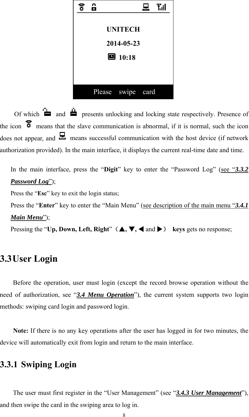
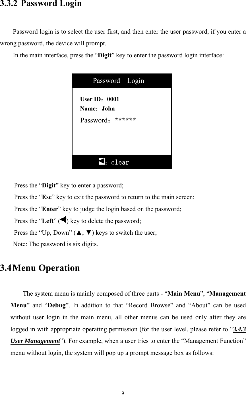
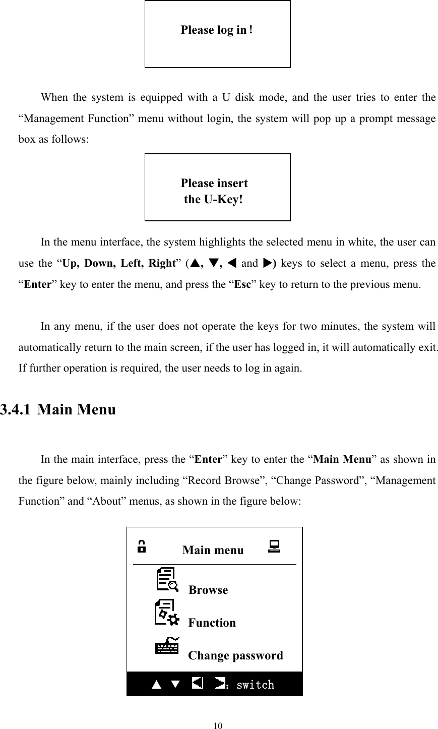
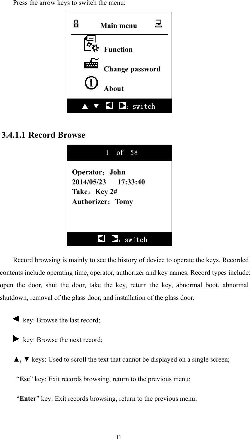
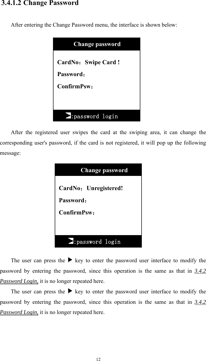
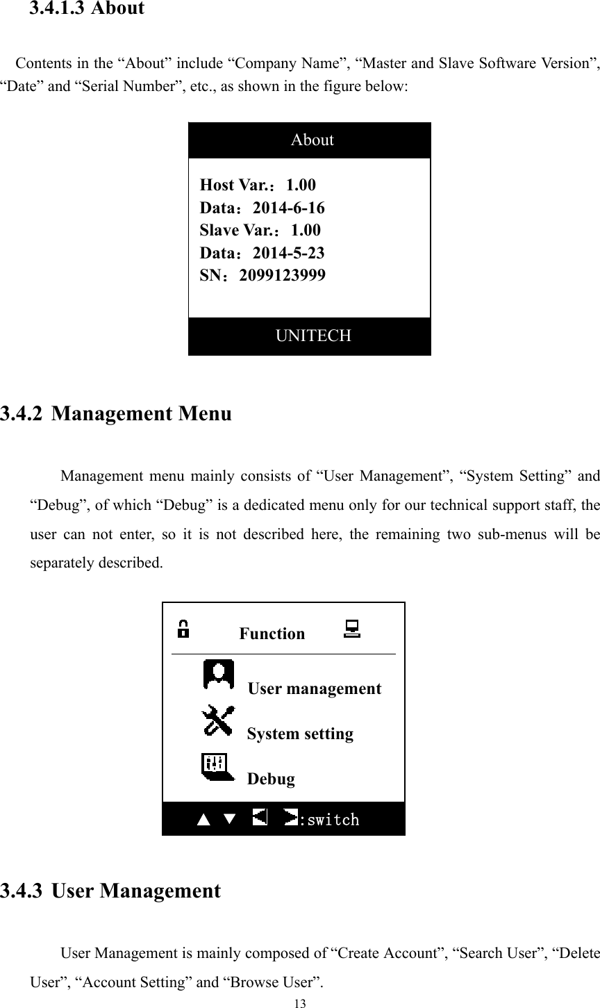
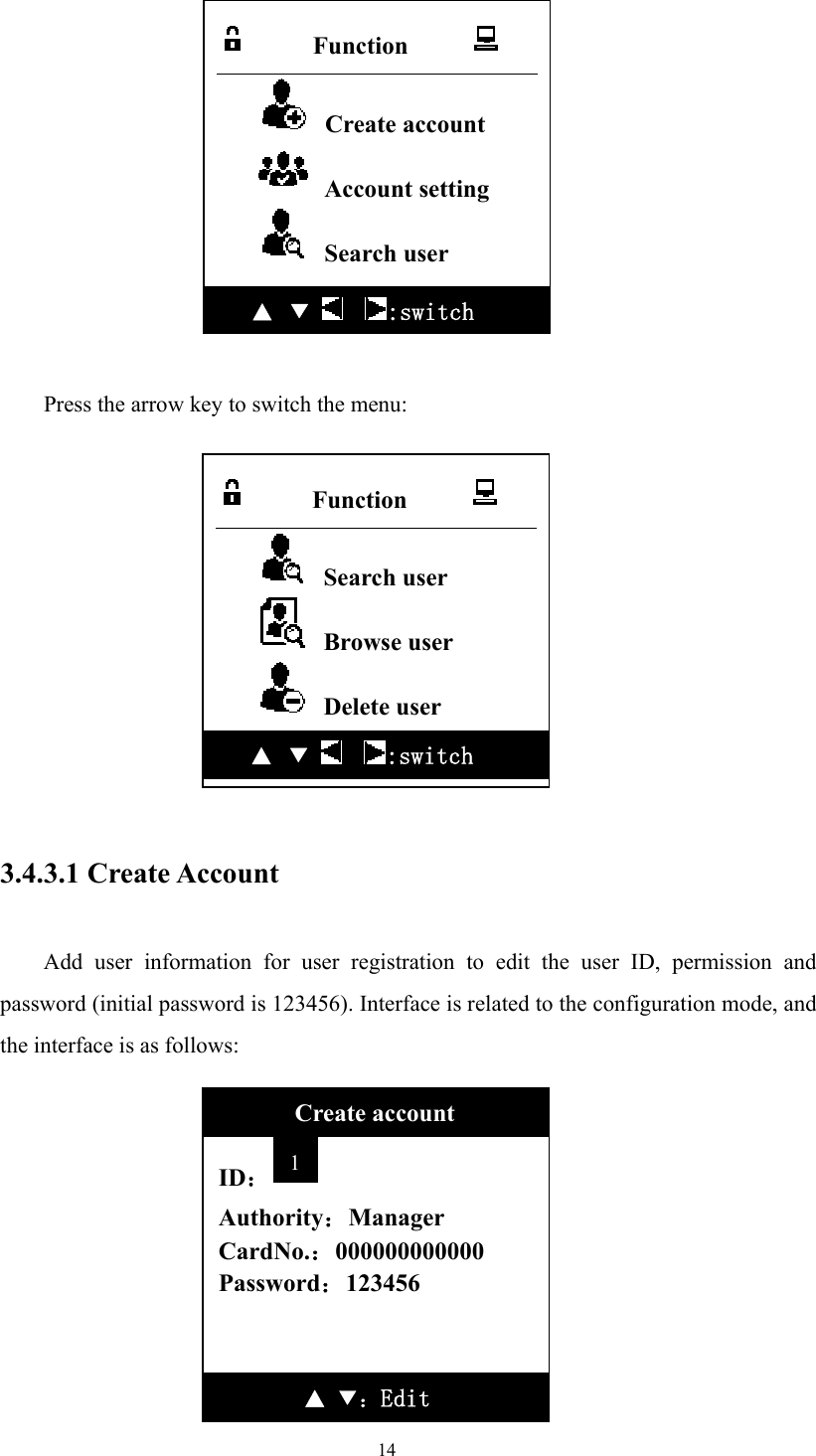
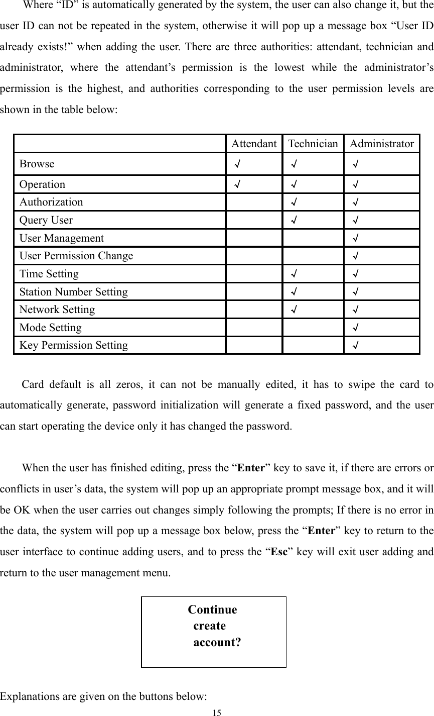
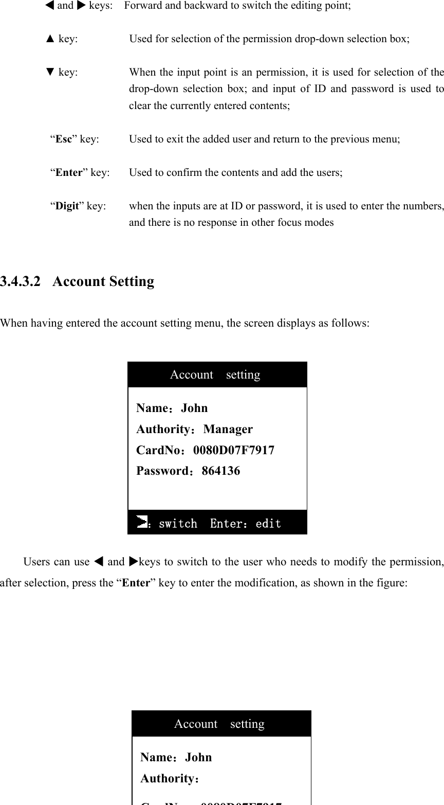
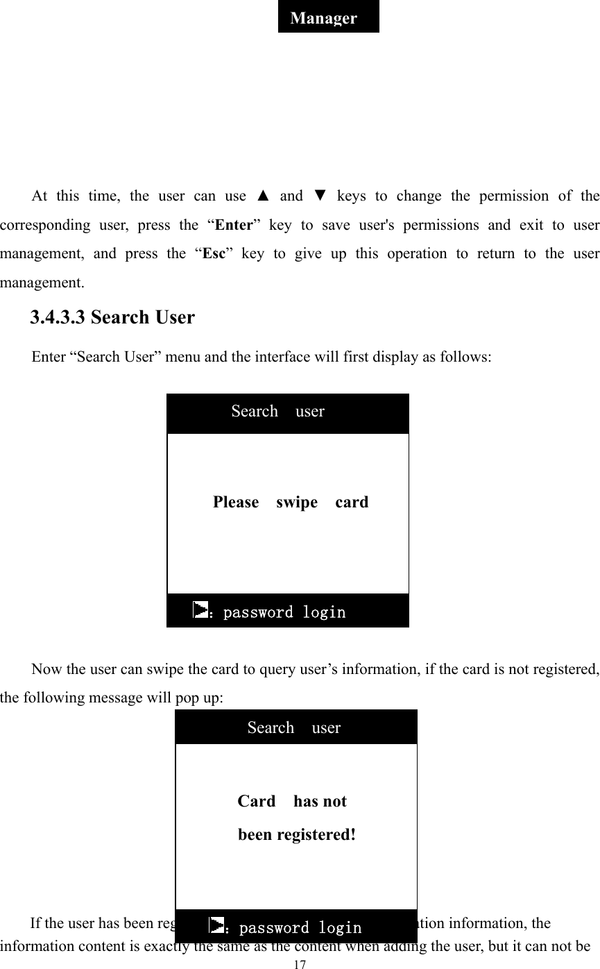
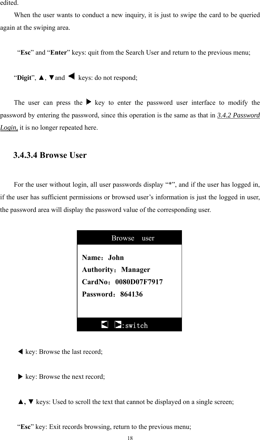
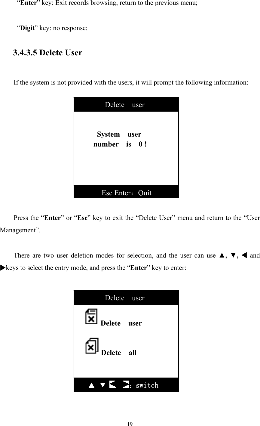
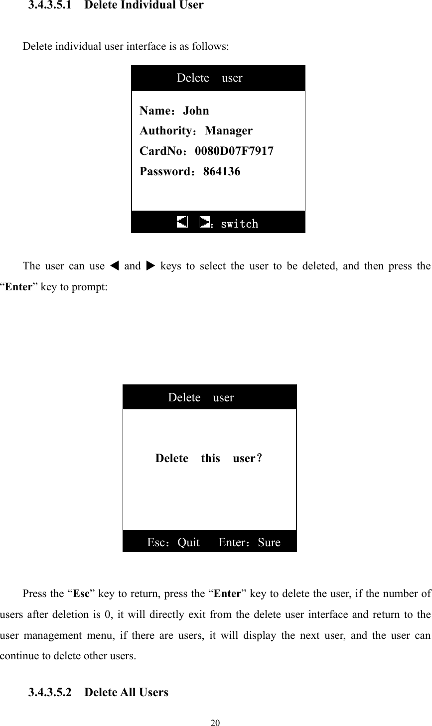
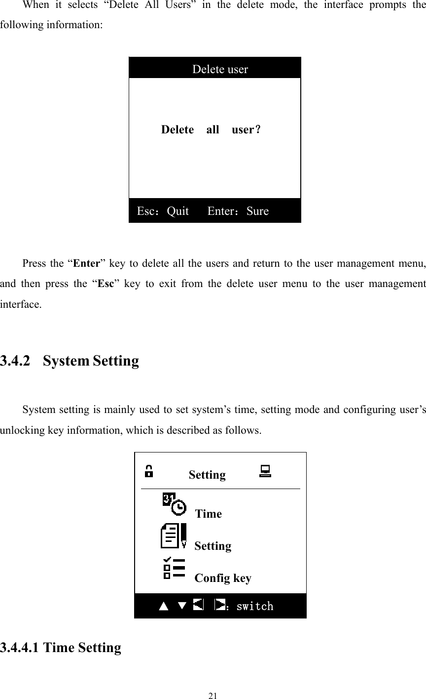
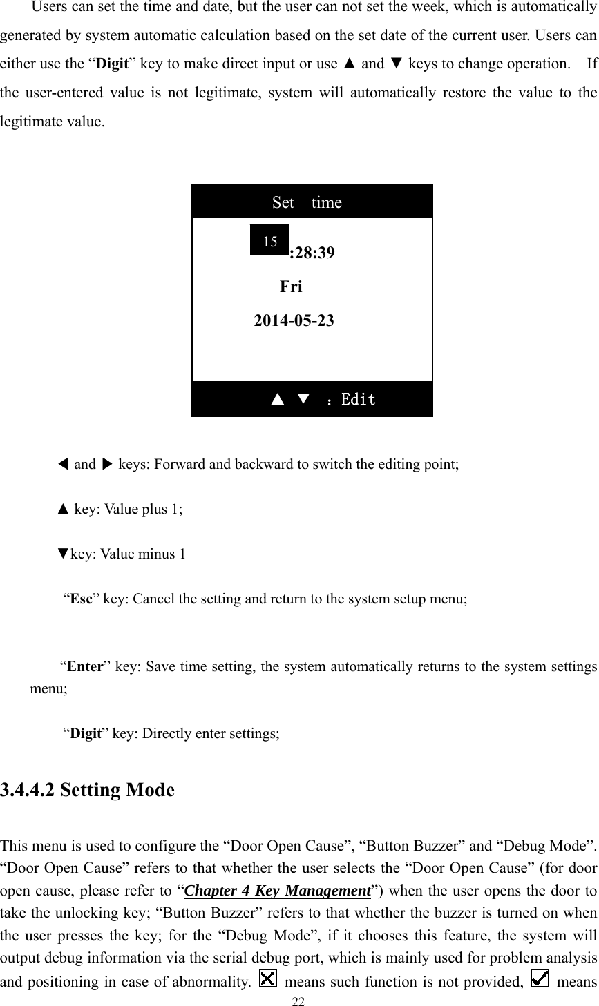
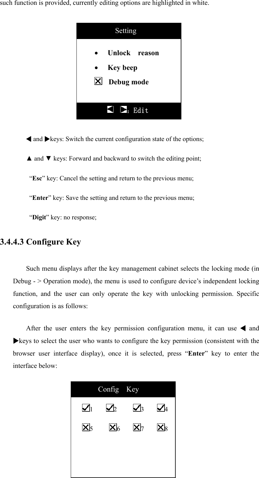
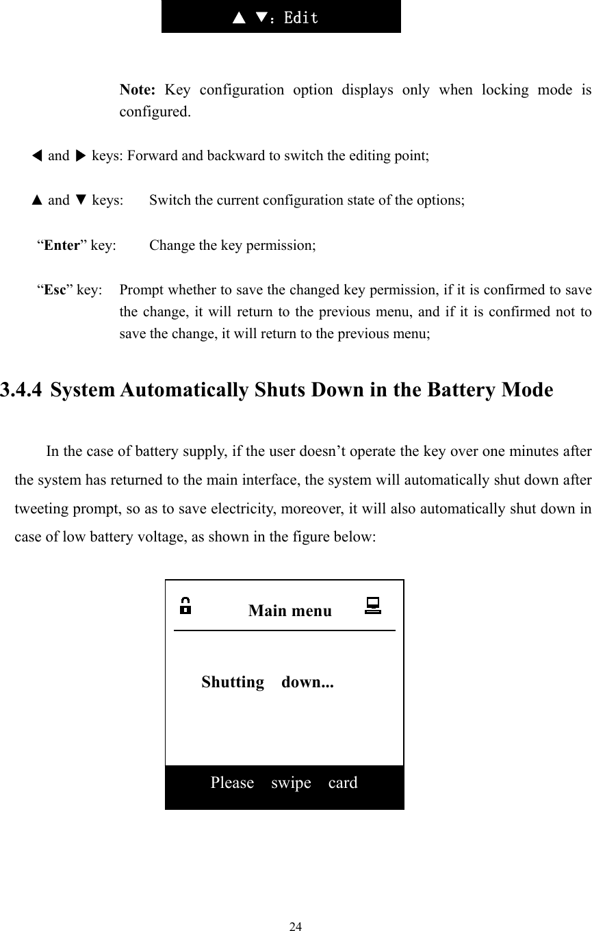
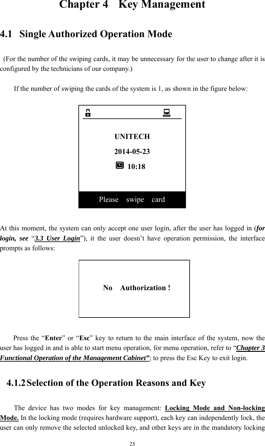
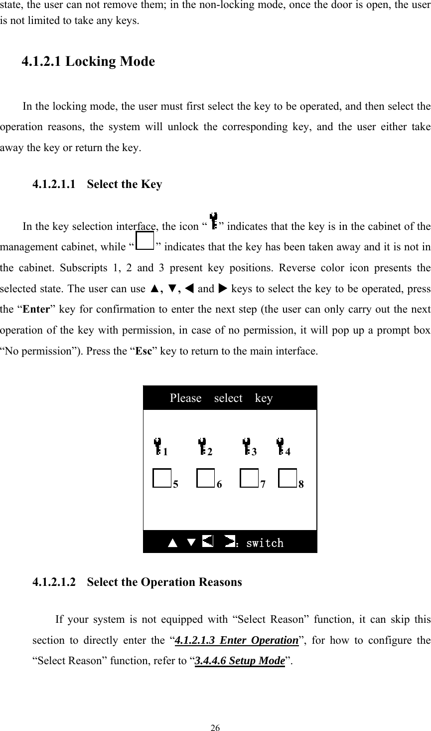
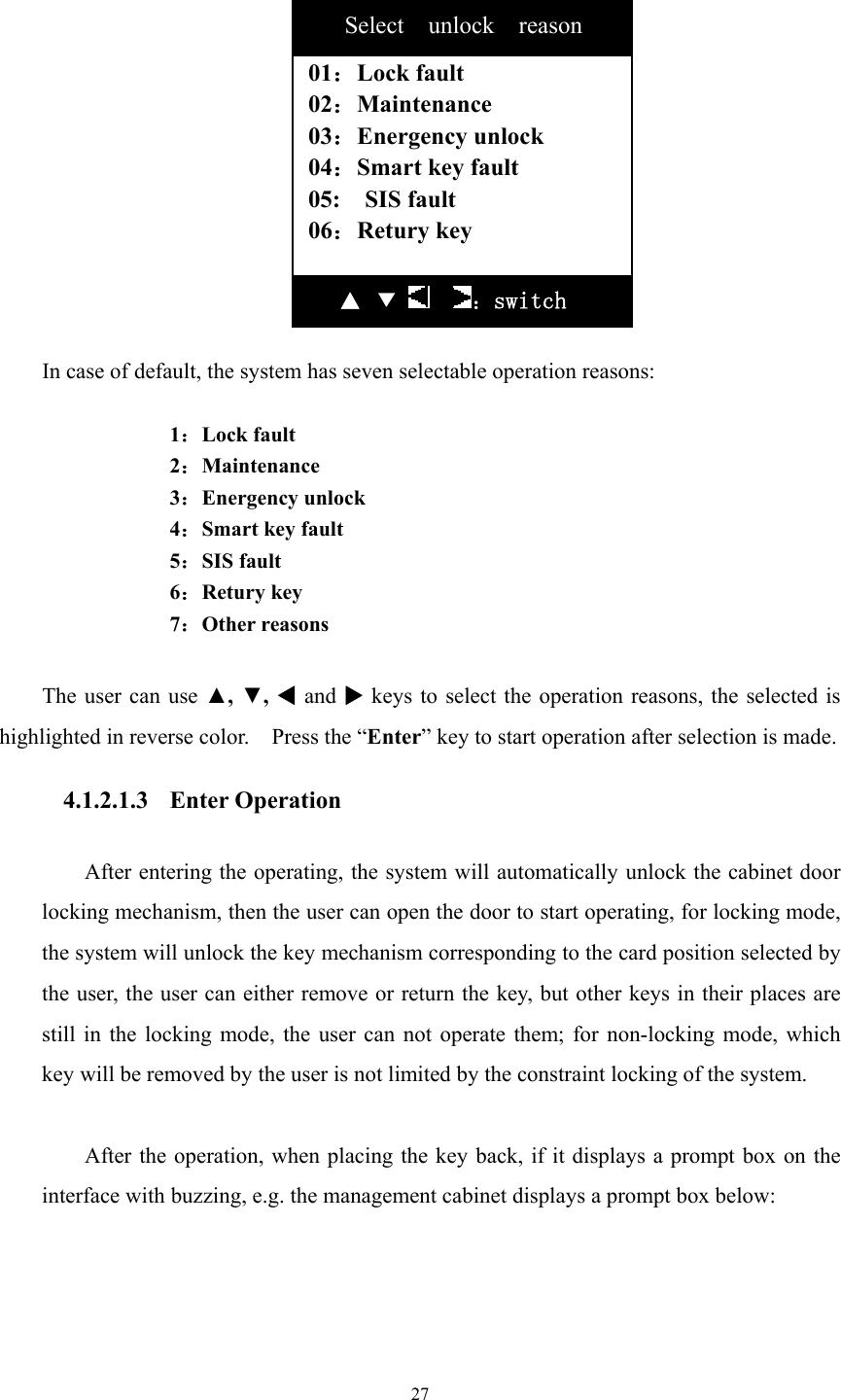
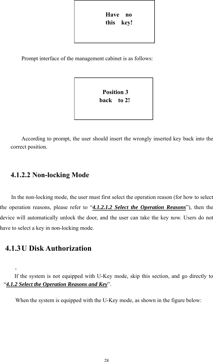
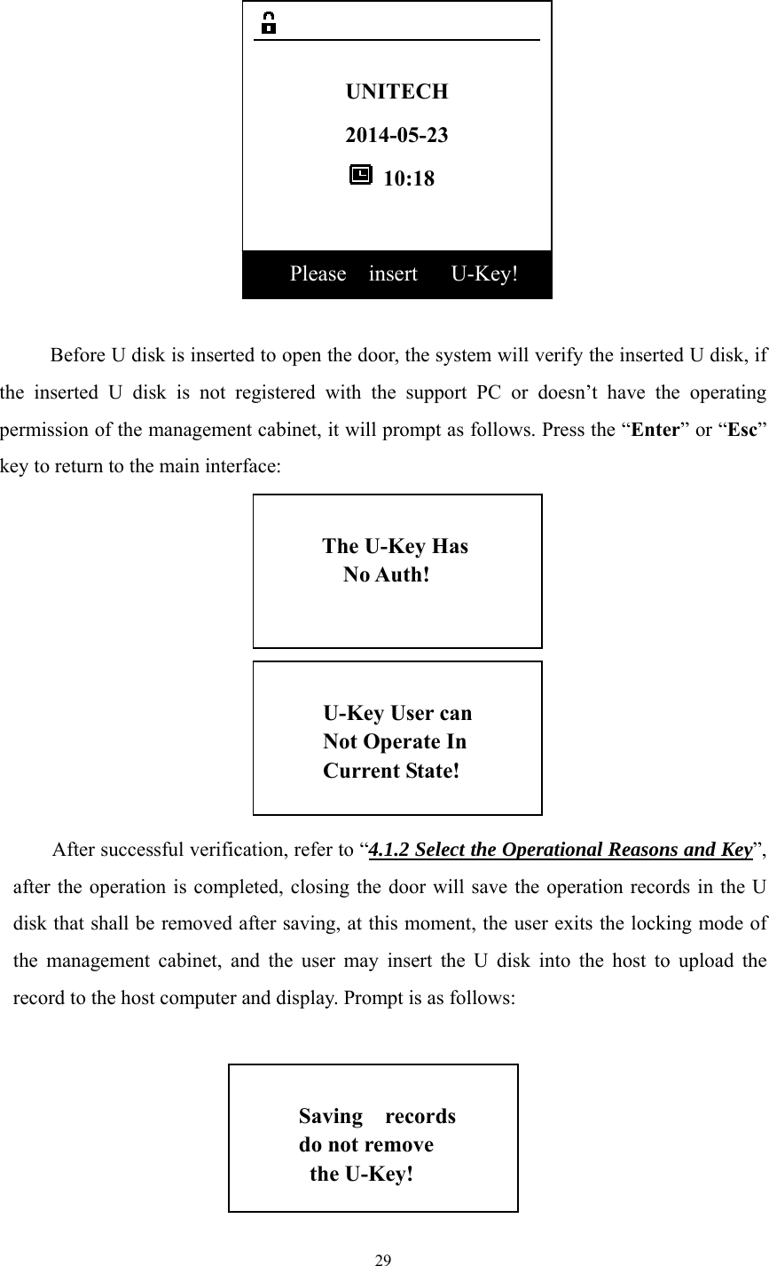
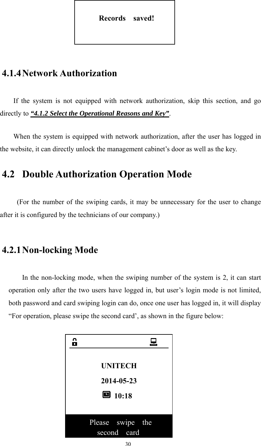
![iv Reading Guide Manual Target: This manual aims at providing operating instructions for UT-059B_UL key management cabinet provided by Zhuhai Unitech Power Technology Co., Ltd., which will enable the users to basically understand product functions, performance and features, and to master the device usages and maintenance methods. Readers: This manual is prepared for the users of UT-059B_UL key management cabinet, main contents cover installation, maintenance and operation of the device, and main role is to provide the installation and operation personnel with installation guidelines and operating procedure descriptions. Manual Composition: This manual is mainly composed by the “Overview”, “System Description”, “Management cabinet Function Operation”, “Key Management” and “Common Questions Handling”. Manual Convention: [Note] This document is subject to change without notice due to the product version upgrades or other reasons. Unless otherwise agreed, this document only serves as a guide, and all statements, information and recommendations in this document do not constitute any express or implied warranty.](https://usermanual.wiki/Zhuhai-Unitech-Power-Technology/UT-059B-UL/User-Guide-2340699-Page-4.png)