Zhuhai Unitech Power Technology UT-059B-UL Key Management Cabinet User Manual UT 059B UL
Zhuhai Unitech Power Technology Co., Ltd. Key Management Cabinet UT 059B UL
Users Manual

i
Data No.:
Version No.:
UT-059B_UL Key Management Cabinet
Operating Manual
Total 37 page(s)
Zhuhai Unitech Power Technology Co., Ltd.
May 23, 2014

ii
Document Revision History
Date Ver si on Revised contents Reviser Approver
05-23-2014 V1.0 Initial version Zhang Le

iii
Copyright
Copyright of the “UT-059B_UL Key Management Cabinet Operating Manual” belongs to
Zhuhai Unitech Power Technology Co., Ltd. Without the written permission of Zhuhai Unitech
Power Technology Co., Ltd., any part of this manual shall not be reproduced or distributed in any
form, by any means (electronic or mechanical, including photocopying or recording), or for any
purpose.
(c) Copyright 2014, Zhuhai Unitech Power Technology Co., Ltd., all rights reserved,
any reproduction will be investigated.
Registered by Zhuhai Unitech Power Technology Co., Ltd.

iv
Reading Guide
Manual Target:
This manual aims at providing operating instructions for UT-059B_UL key
management cabinet provided by Zhuhai Unitech Power Technology Co., Ltd., which
will enable the users to basically understand product functions, performance and features,
and to master the device usages and maintenance methods.
Readers:
This manual is prepared for the users of UT-059B_UL key management cabinet,
main contents cover installation, maintenance and operation of the device, and main role
is to provide the installation and operation personnel with installation guidelines and
operating procedure descriptions.
Manual Composition:
This manual is mainly composed by the “Overview”, “System Description”,
“Management cabinet Function Operation”, “Key Management” and “Common
Questions Handling”.
Manual Convention:
[Note] This document is subject to change without notice due to the product
version upgrades or other reasons. Unless otherwise agreed, this document only serves as
a guide, and all statements, information and recommendations in this document do not
constitute any express or implied warranty.
v
Table of Contents
Chapter 1 Overview .................................................................... 1
1.1 Technical Features ........................................................................................... 2
1.2 System Technical Parameters ........................................................................... 3
Chapter 2 System Description .................................................... 4
2.1 Dimensions ...................................................................................................... 4
2.2 Installation Dimensions ................................................................................... 4
2.3 Wiring Socket Instructions ............................................................................... 5
2.4 Indicator Description ....................................................................................... 6
2.5 Backup Battery ................................................................................................. 6
Chapter 3 Functional Operation of the Control Device ........... 7
3.1 System Start ..................................................................................................... 7
3.2 The Main Interface ........................................................................................... 7
3.3 User Login ....................................................................................................... 8
3.3.1 Swiping Login ................................................................................... 8
3.3.2 Password Login ................................................................................. 9
3.4 Menu Operation ............................................................................................... 9
3.4.1 Main Menu ...................................................................................... 10
3.4.1.1 Record Browse ......................................................................................... 11
3.4.1.2 Change Password ..................................................................................... 12
3.4.1.3 About ........................................................................................................ 13
3.4.2 Management Menu .......................................................................... 13
3.4.3 User Management ............................................................................ 13
3.4.3.1 Adding Users ............................................................................................ 14
3.4.3.2 Configuration Permission ......................................................................... 16
3.4.3.3 Query User ............................................................................................... 17
3.4.3.4 Users Browse ........................................................................................... 18
3.4.3.5 Delete User ............................................................................................... 19
3.4.3.5.1 Delete Individual User .................................................................. 20
3.4.3.5.2 Delete All Users ............................................................................ 20
3.4.2 System Setting ................................................................................. 21
3.4.4.1 Time Setting ............................................................................................. 21
3.4.4.2 Setting Mode ............................................................................................ 22
3.4.4.3 Configure Keys ........................................................................................ 23
3.4.4 System Automatically Shuts Down in the Battery Mode ................ 24
Chapter 4 Key Management .................................................... 25
vi
4.1 Single Authorized Operation Mode ............................................................... 25
4.1.2 Selection of the Operation Reasons and Key .................................. 25
4.1.2.1 Locking Mode .......................................................................................... 26
4.1.2.1.1 Select the Key................................................................................ 26
4.1.2.1.2 Select the Operation Reasons ........................................................ 26
4.1.2.1.3 Enter Operation ............................................................................. 27
4.1.2.2 Non-locking Mode ................................................................................... 28
4.1.3 U Disk Authorization ....................................................................... 28
4.1.4 Network Authorization .................................................................... 30
4.2 Double authorization Operation Mode .......................................................... 30
4.2.1 Locking Mode ................................................................................. 30
4.2.2 Locking Mode ................................................................................. 31
4.3 MultiplayerAuthorization Operation Mode ................................................... 34
4.5 Operation in Case of Emergency ................................................................... 34
Chapter 5 Remedy of the Common Problems ........................ 35

1
Chapter 1 Overview
Currently, many substations and power plants introduce microcomputer safety interlock devices,
and those devices have provided the safe operation of the power production with strong guarantee.
However, it is short of effective and feasible methods to manage some special unlocking keys used by
these devices, thereby directly affecting the safe production of power system. To this end our
company has developed UT-059B_UL key management cabinet that can better resolve this problem.
UT-059B_UL key management cabinet is a microcomputer-controlled management device,
which can not only manage electric unlocking key, jumping key and mechanical unlocking key, but
also manage various door keys, computer keys and even mobile phones and wallets. UT-059B_UL
key management cabinet uses non-contact IC card, network authorization and SMS authorization; by
use of the advanced RFID detection technology, when a user takes away from or return the unlocking
key to the key management cabinet, the management cabinet will exactly record the specific date to
take away from or return the unlocking key to the management cabinet, records are detailed and
accurate, so it can greatly reduce troubles resulted from the manual management of these locks. A
full Chinese LCD display is designed, the entire menu interface is simple and friendly, so it greatly
improves automation management of the power plant.
UT-059B_UL model key management cabinet is a FCC certified product, which current model is
not support the SMS function.
FCC Caution
§ 15.19 Labelling requirements.
This device complies with part 15 of the FCC Rules. Operation is subject to the following
two conditions: (1) This device may not cause harmful interference, and (2) this device must
accept any interference received, including interference that may cause undesired operation.
§ 15.21 Information to user.
Any Changes or modifications not expressly approved by the party responsible for
compliance could void the user's authority to operate the equipment.
§ 15.105 Information to the user.
Note: This equipment has been tested and found to comply with the limits for a Class B
digital device, pursuant to part 15 of the FCC Rules. These limits are designed to provide
reasonable protection against harmful interference in a residential installation. This
equipment generates uses and can radiate radio frequency energy and, if not installed and
used in accordance with the instructions, may cause harmful interference to radio
communications. However, there is no guarantee that interference will not occur in a
particular installation. If this equipment does cause harmful interference to radio or television
reception, which can be determined by turning the equipment off and on, the user is
encouraged to try to correct the interference by one or more of the following measures:
-Reorient or relocate the receiving antenna.
-Increase the separation between theequipment and receiver.
-Connect the equipment into an outlet on a circuit different from that to which the receiver is
2
connected.
-Consult the dealer or an experienced radio/TV technician for help.
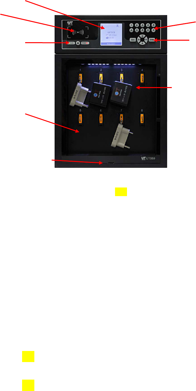
Fig. 1-1 External view of UT-059B_UL key management cabinet
1.1 Technical Features
High basic frequency ARM 7 industrial grade host machine is the core of the system;
160*160 monochrome display, grayscale adjustable;
RFID identification technology;
IC card authorization, manage users’ different permissions;
WEB management, it can use a browser to monitor relevant information of the management
cabinet and configure relevant parameters of the system;
With perfect record function, supporting up to 6,000 messages;
Support ethernet communication;
UT-059B_UL supports USB interface, facilitate the operation and control of the device
through a U disk, thus achieving operation data import and export;
UT-059B_UL structured case design, wall mounted or desktop installation modes;
Cabinet
door
Organic glass,
removable in case
of emergency
Swiping
area
Power button,
power supply,
running indicator
Display
Digital input
area
Operating
button
Key storage
area

3
Support both locking and non-locking modes;
With lighting function;
Provides rechargeable battery as a backup power supply, operational in case of a blackout
condition.
1.2 System Technical Parameters
Ambient temperature: -20℃~+70℃
Relative humidity: Daily average ≤ 95%, monthly average ≤ 90%
Quiescent current: UT-059B_UL≤200mA
Internal memory capacity: FLASH≥4MB,RAM≥1MB,DataFlash ≥2MB
Dielectric strength: ≥2000V
RFI strength: ≥50dB(uV/m)
Anti-power terminal transmission interference strength:≥70dd(uV)
Impact strength: ≥10g
Mean trouble free time (MTBF): ≥50000h
Data minimum storage: 10 years
Maximum saved records: 6000
Input voltage range: 85~265VAC,110~330VDC
4
Chapter 2 System Description
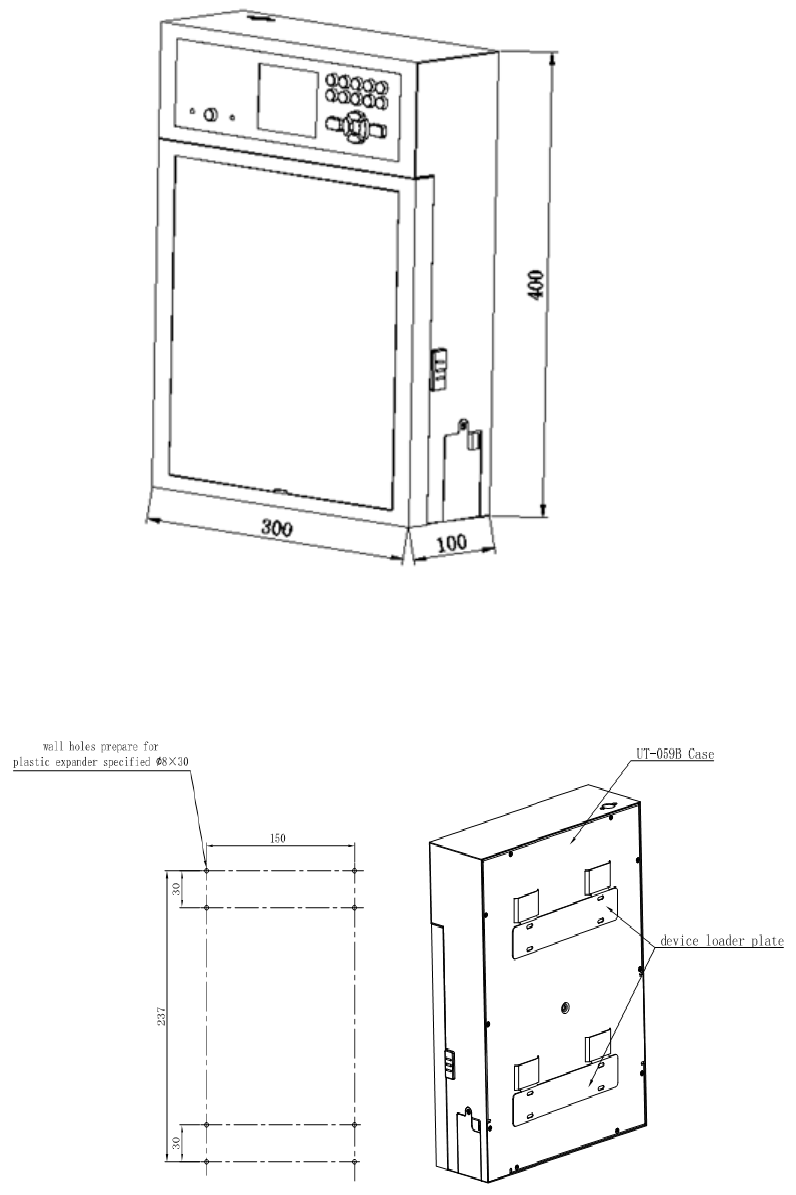
2.1 Dimensions
Fig. 2-1 UT-059B_UL dimensions
2.2 Installation Dimensions
Fig. 2-2 UT-059B_UL installation and holing sizes Fig. 2-3 UT-059B_UL wall installation
5
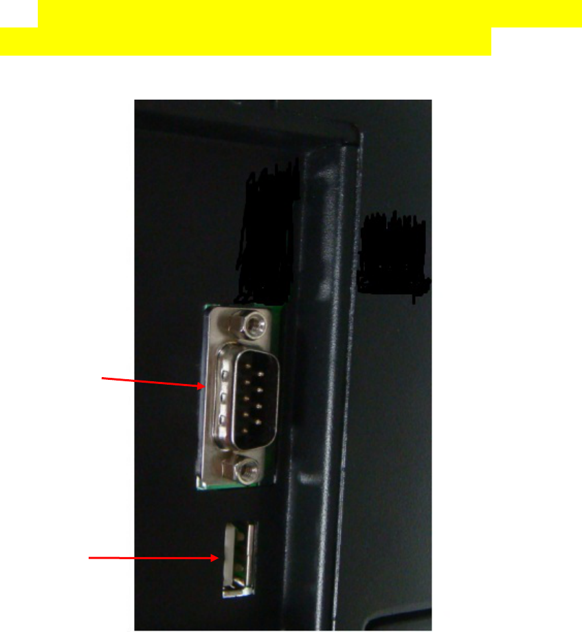
2.3 Wiring Socket Instructions
UT-059B_UL key management cabinet have multi-interface, Serial port and USB port
are located on the top side of the left of the device, As shown in the figure below:
Fig. 2-4 debugging port and USB interface
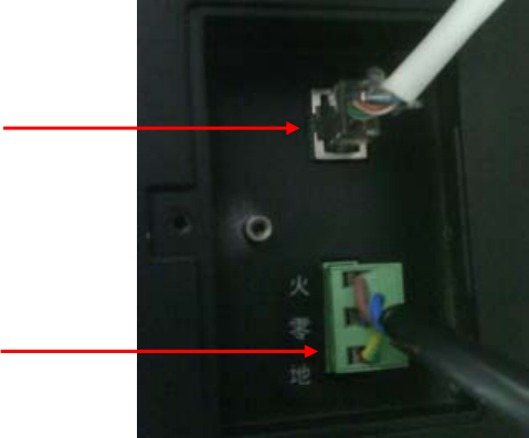
Ethernet port and power socket is located at the lower right side of the device, as shown in Fig.
below:
USB
interface
Debugging
port
6
Fig. 2-5 UT-059B_UL ethernet port and power socket
2.4 Indicator Description
There are two indicators on the system panel: one power indicator and one running indicator.
After the power is turned on, if the power indicator remains red, it means that it is using external
AC220 to supply the power, if the power indicator becomes green, it indicates that the current power
is supplied by the battery; and the running indicator is green and flashes once per second.
2.5 Backup Battery
Backup battery of the system will automatically be charged after the power is below a certain
level, it is unnecessary for users to intervene, the device can automatically detect and identify the
current power supply mode and make internal and external power supply switching. In the case of
fully charged battery, the UT-059B_UL device is continuously powered by the battery for about 12
hours. In the case of battery power supply, when the system returns to the main interface, if there is
no operation over one minute, the system will automatically shut down to save electricity. After the
device is automatically shut down in the case of the battery supply, if the external AC220V supplies
the power, the device will automatically turn on to start working.
Power
socket
Network

7
Chapter 3 Functional Operation of the Management
Cabinet
The following is an introduction of the operating methods of the UT-059B_UL key
management cabinet (hereinafter referred to as the “device”).
3.1 System Start
It shall turn on the system power supply, then press the power button for about two
seconds to start the system, in case of an unexpected blackout, if the power is turned on, the
device will automatic start, and without external power but with battery power, to press the
power button about two seconds can also start the device. After the power is turned on about 2
seconds, the LCD display enters the boot interface, and screenshot is shown below:
(1) In the boot interface, if the user does not carry out any operation, the system will
automatically enter the main interface after 10 seconds.
(2) In the boot interface, in the case of any key operation or swiping card, the system will
immediately enter the main interface.
3.2 The Main Interface
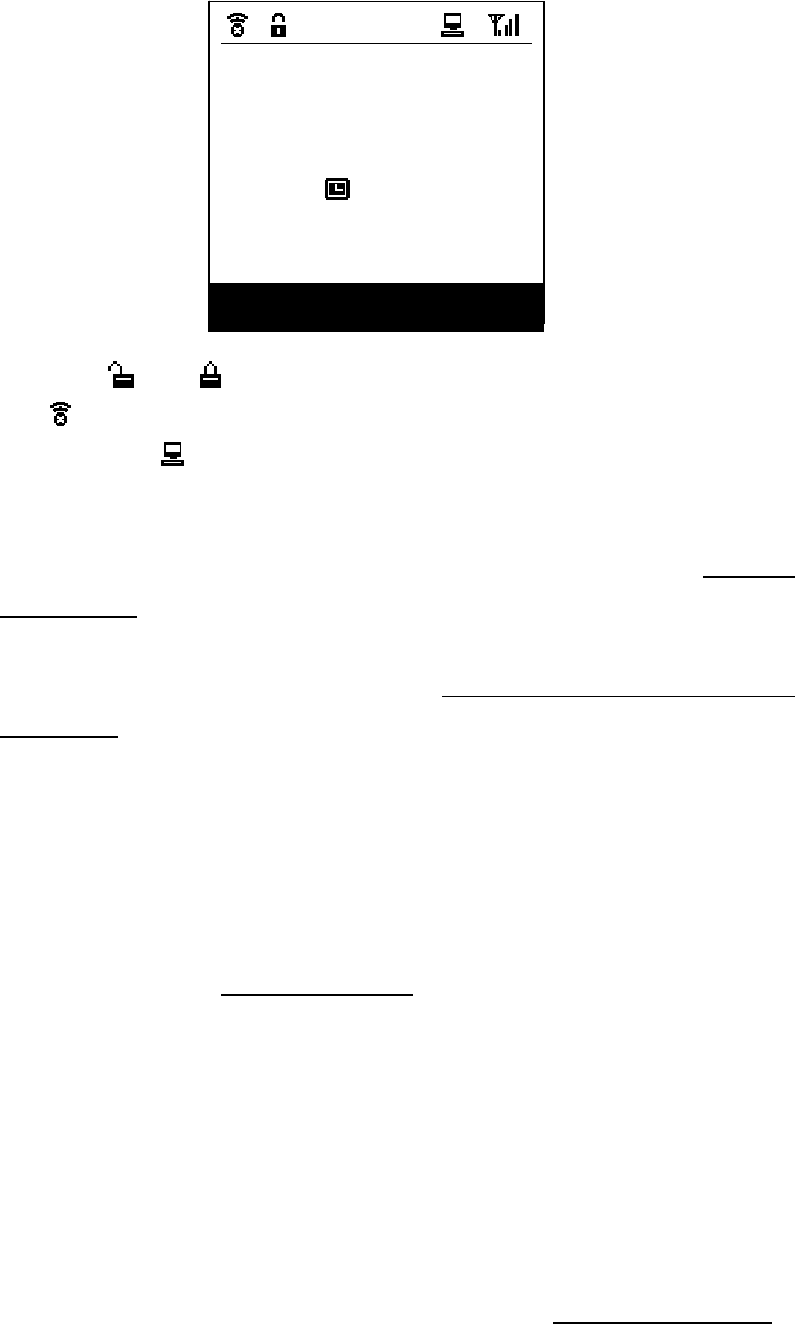
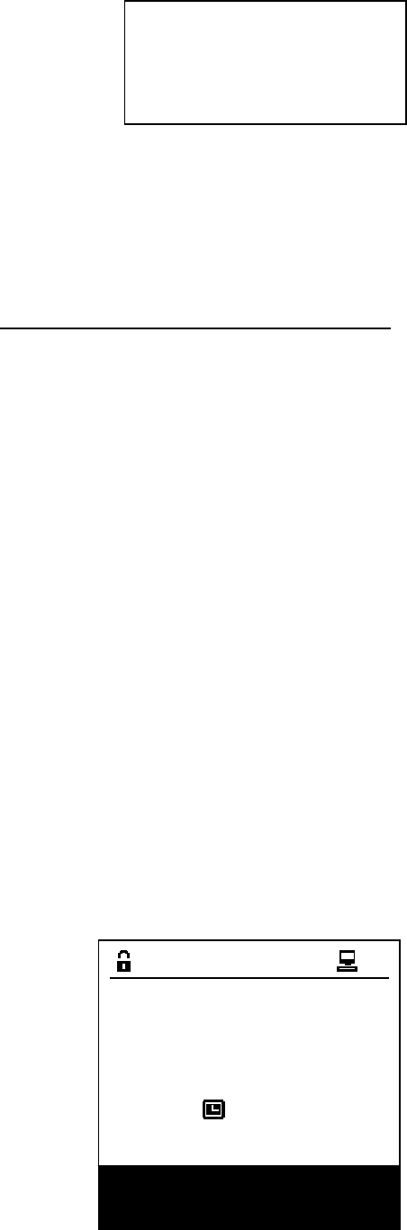
The figure below is a typical main interface equipped with the network authorization:
8
Of which and presents unlocking and locking state respectively. Presence of
the icon means that the slave communication is abnormal, if it is normal, such the icon
does not appear, and means successful communication with the host device (if network
authorization provided). In the main interface, it displays the current real-time date and time.
In the main interface, press the “Digit” key to enter the “Password Log” (see “3.3.2
Password Log”);
Press the “Esc” key to exit the login status;
Press the “Enter” key to enter the “Main Menu” (see description of the main menu “3.4.1
Main Menu”);
Pressing the “Up, Down, Left, Right”(, , and ) keys gets no response;
3.3 User Login
Before the operation, user must login (except the record browse operation without the
need of authorization, see “3.4 Menu Operation”), the current system supports two login
methods: swiping card login and password login.
Note: If there is no any key operations after the user has logged in for two minutes, the
device will automatically exit from login and return to the main interface.
3.3.1 Swiping Login
The user must first register in the “User Management” (see “3.4.3 User Management”),
and then swipe the card in the swiping area to log in.
UNITECH
2014-05-23
10:18
Please swipe card
9
3.3.2 Password Login
Password login is to select the user first, and then enter the user password, if you enter a
wrong password, the device will prompt.
In the main interface, press the “Digit” key to enter the password login interface:
Press the “Digit” key to enter a password;
Press the “Esc” key to exit the password to return to the main screen;
Press the “Enter” key to judge the login based on the password;
Press the “Left” ( ) key to delete the password;
Press the “Up, Down” (▲, ▼) keys to switch the user;
Note: The password is six digits.
3.4 Menu Operation
The system menu is mainly composed of three parts - “Main Menu”, “Management
Menu” and “Debug”. In addition to that “Record Browse” and “About” can be used
without user login in the main menu, all other menus can be used only after they are
logged in with appropriate operating permission (for the user level, please refer to “3.4.3
User Management”). For example, when a user tries to enter the “Management Function”
menu without login, the system will pop up a prompt message box as follows:
User ID:0001
Name:John
Password:******
Password Login
:clear
10
When the system is equipped with a U disk mode, and the user tries to enter the
“Management Function” menu without login, the system will pop up a prompt message
box as follows:
In the menu interface, the system highlights the selected menu in white, the user can
use the “Up, Down, Left, Right” (, , and ) keys to select a menu, press the
“Enter” key to enter the menu, and press the “Esc” key to return to the previous menu.
In any menu, if the user does not operate the keys for two minutes, the system will
automatically return to the main screen, if the user has logged in, it will automatically exit.
If further operation is required, the user needs to log in again.
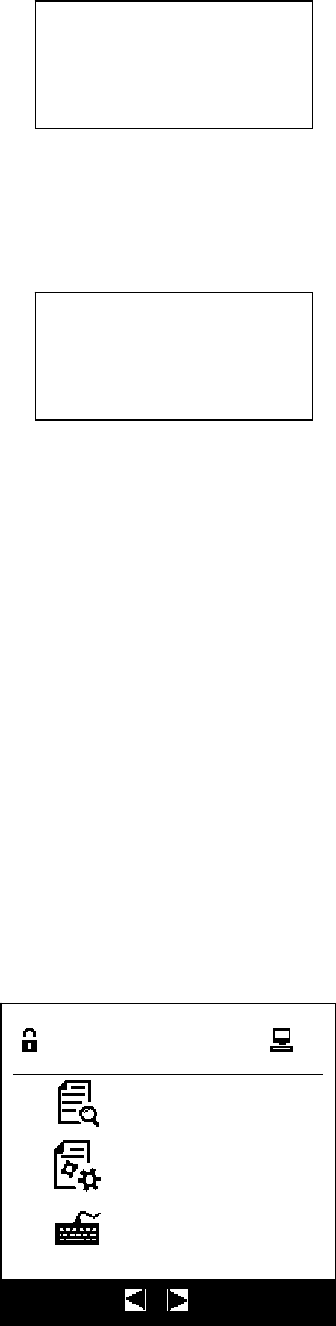
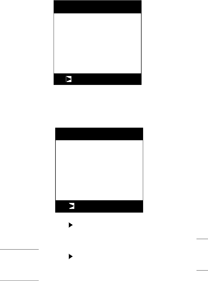
3.4.1 Main Menu
In the main interface, press the “Enter” key to enter the “Main Menu” as shown in
the figure below, mainly including “Record Browse”, “Change Password”, “Management
Function” and “About” menus, as shown in the figure below:
Main menu
Browse
Function
Change password
▲ ▼ :switch
Please log in!
Please insert
the U-Key!
11
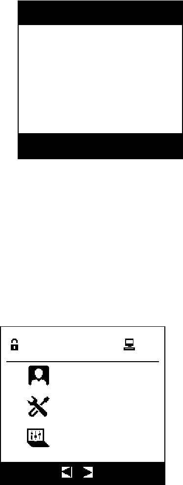
Press the arrow keys to switch the menu:
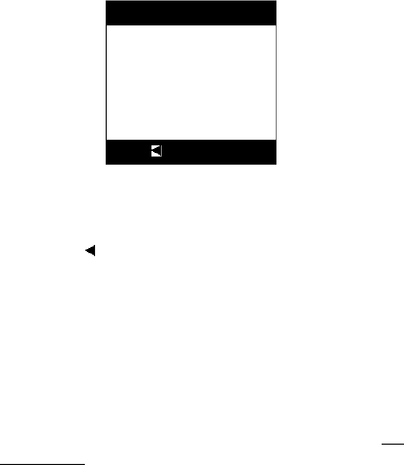
3.4.1.1 Record Browse
Record browsing is mainly to see the history of device to operate the keys. Recorded
contents include operating time, operator, authorizer and key names. Record types include:
open the door, shut the door, take the key, return the key, abnormal boot, abnormal
shutdown, removal of the glass door, and installation of the glass door.
key: Browse the last record;
key: Browse the next record;
▲, ▼ keys: Used to scroll the text that cannot be displayed on a single screen;
“Esc” key: Exit records browsing, return to the previous menu;
“Enter” key: Exit records browsing, return to the previous menu;
Operator:John
2014/05/23 17:33:40
Take:Key 2#
Authorizer:Tomy
1 of 58
:switch
Main menu
Function
Change password
About
▲ ▼ :switch
12
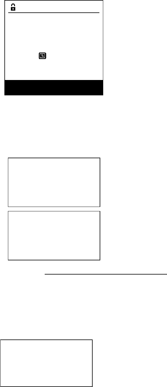
3.4.1.2 Change Password
After entering the Change Password menu, the interface is shown below:
After the registered user swipes the card at the swiping area, it can change the
corresponding user's password, if the card is not registered, it will pop up the following
message:
The user can press the key to enter the password user interface to modify the
password by entering the password, since this operation is the same as that in 3.4.2
Password Login, it is no longer repeated here.
The user can press the key to enter the password user interface to modify the
password by entering the password, since this operation is the same as that in 3.4.2
Password Login, it is no longer repeated here.
CardNo:Swipe Card !
Password:
ConfirmPsw:
:
p
assword lo
g
in
Change password
CardNo:Unregistered!
Password:
ConfirmPsw:
Change password
:password login
13
3.4.1.3 About
Contents in the “About” include “Company Name”, “Master and Slave Software Version”,
“Date” and “Serial Number”, etc., as shown in the figure below:
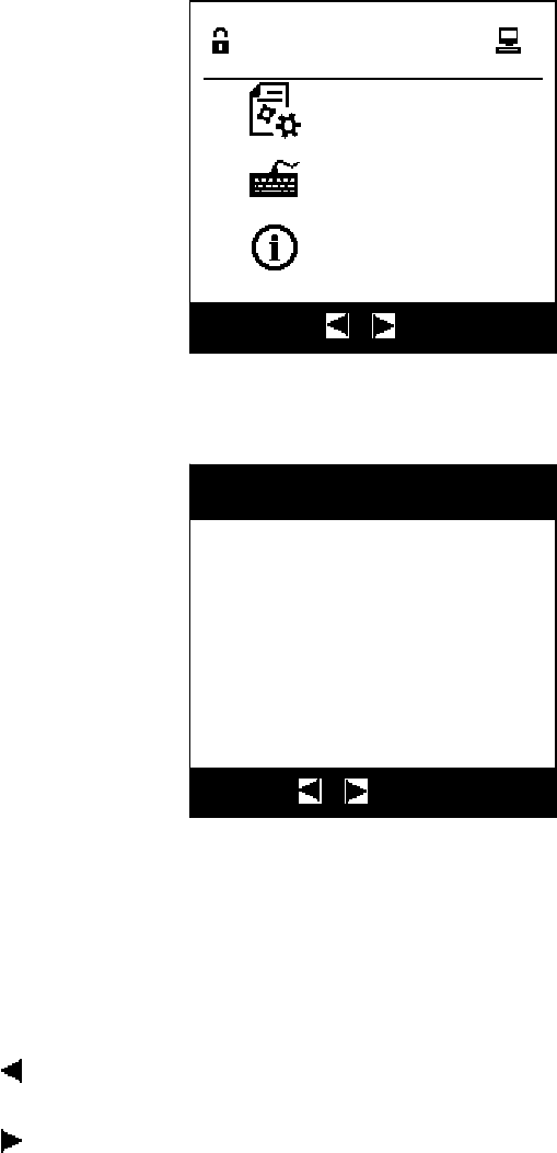
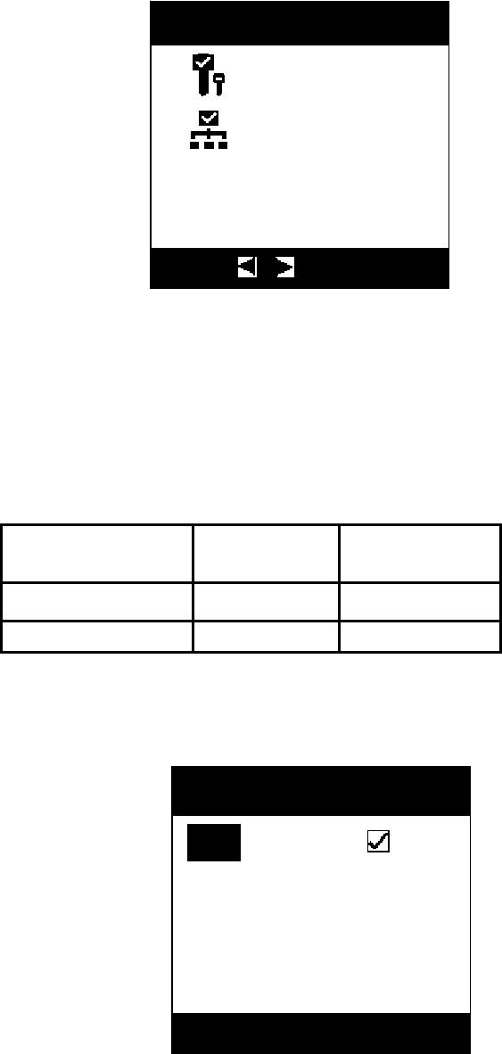
3.4.2 Management Menu
Management menu mainly consists of “User Management”, “System Setting” and
“Debug”, of which “Debug” is a dedicated menu only for our technical support staff, the
user can not enter, so it is not described here, the remaining two sub-menus will be
separately described.
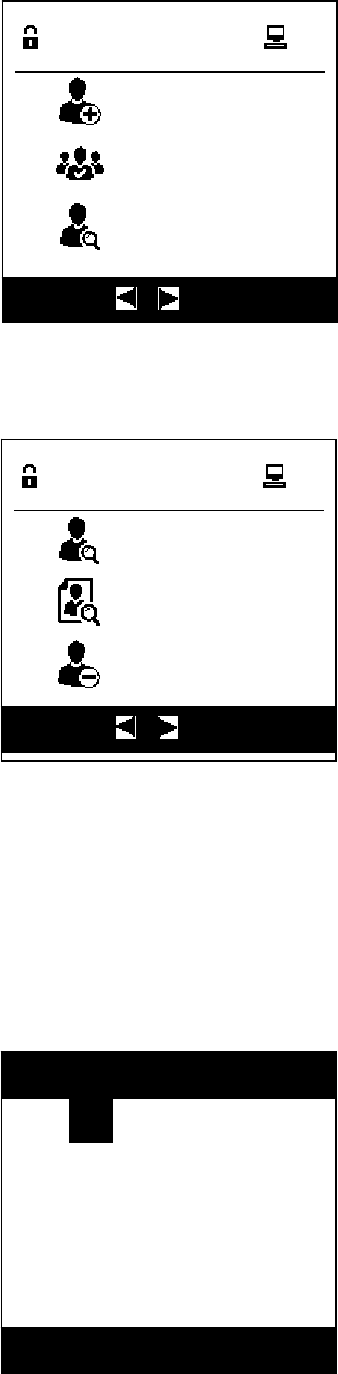
3.4.3 User Management
User Management is mainly composed of “Create Account”, “Search User”, “Delete
User”, “Account Setting” and “Browse User”.
Host Var.:1.00
Data:2014-6-16
Slave Var.:1.00
Data:2014-5-23
SN:2099123999
About
UNITECH
Function
User management
System setting
Debug
▲ ▼ :switch
14
Press the arrow key to switch the menu:
3.4.3.1 Create Account
Add user information for user registration to edit the user ID, permission and
password (initial password is 123456). Interface is related to the configuration mode, and
the interface is as follows:
Function
Create account
Account setting
Search user
▲ ▼ :switch
ID:
Authority:Manager
CardNo.:000000000000
Password:123456
Create account
▲ ▼:Edit
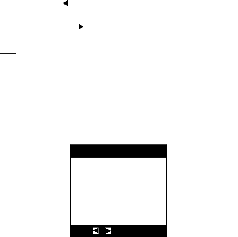
Function
Search user
Browse user
Delete user
▲ ▼ :switch
1

15
Where “ID” is automatically generated by the system, the user can also change it, but the
user ID can not be repeated in the system, otherwise it will pop up a message box “User ID
already exists!” when adding the user. There are three authorities: attendant, technician and
administrator, where the attendant’s permission is the lowest while the administrator’s
permission is the highest, and authorities corresponding to the user permission levels are
shown in the table below:
Attendant Technician Administrator
Browse √ √ √
Operation √ √ √
Authorization √ √
Query User √ √
User Management √
User Permission Change √
Time Setting √ √
Station Number Setting √ √
Network Setting √ √
Mode Setting √
Key Permission Setting √
Card default is all zeros, it can not be manually edited, it has to swipe the card to
automatically generate, password initialization will generate a fixed password, and the user
can start operating the device only it has changed the password.
When the user has finished editing, press the “Enter” key to save it, if there are errors or
conflicts in user’s data, the system will pop up an appropriate prompt message box, and it will
be OK when the user carries out changes simply following the prompts; If there is no error in
the data, the system will pop up a message box below, press the “Enter” key to return to the
user interface to continue adding users, and to press the “Esc” key will exit user adding and
return to the user management menu.
Explanations are given on the buttons below:
Continue
create
account?

16
and keys: Forward and backward to switch the editing point;
▲ key: Used for selection of the permission drop-down selection box;
▼ key: When the input point is an permission, it is used for selection of the
drop-down selection box; and input of ID and password is used to
clear the currently entered contents;
“Esc” key: Used to exit the added user and return to the previous menu;
“Enter” key: Used to confirm the contents and add the users;
“Digit” key: when the inputs are at ID or password, it is used to enter the numbers,
and there is no response in other focus modes
3.4.3.2 Account Setting
When having entered the account setting menu, the screen displays as follows:
Users can use and keys to switch to the user who needs to modify the permission,
after selection, press the “Enter” key to enter the modification, as shown in the figure:
Name:John
Authority:Manager
CardNo:0080D07F7917
Password:864136
Account setting
:switch Enter:edit
Name:John
Authority:
CdN
0080D07F7917
Account setting

17
At this time, the user can use ▲ and ▼ keys to change the permission of the
corresponding user, press the “Enter” key to save user's permissions and exit to user
management, and press the “Esc” key to give up this operation to return to the user
management.
3.4.3.3 Search User
Enter “Search User” menu and the interface will first display as follows:
Now the user can swipe the card to query user’s information, if the card is not registered,
the following message will pop up:
If the user has been registered, it will pop up user’s configuration information, the
information content is exactly the same as the content when adding the user, but it can not be
Mana
g
er
Please swipe card
Search user
:password login
Card has not
been registered!
Search user
:password login
18
edited.
When the user wants to conduct a new inquiry, it is just to swipe the card to be queried
again at the swiping area.
“Esc” and “Enter” keys: quit from the Search User and return to the previous menu;
“Digit”, ▲, ▼and keys: do not respond;
The user can press the key to enter the password user interface to modify the
password by entering the password, since this operation is the same as that in 3.4.2 Password
Login, it is no longer repeated here.
3.4.3.4 Browse User
For the user without login, all user passwords display “*”, and if the user has logged in,
if the user has sufficient permissions or browsed user’s information is just the logged in user,
the password area will display the password value of the corresponding user.
◀ key: Browse the last record;
▶ key: Browse the next record;
▲, ▼ keys: Used to scroll the text that cannot be displayed on a single screen;
“Esc” key: Exit records browsing, return to the previous menu;
Name:John
Name:John
Authority:Manager
CardNo:0080D07F7917
Password:864136
Browse use
r
:switch

19
“Enter” key: Exit records browsing, return to the previous menu;
“Digit” key: no response;
3.4.3.5 Delete User
If the system is not provided with the users, it will prompt the following information:
Press the “Enter” or “Esc” key to exit the “Delete User” menu and return to the “User
Management”.
There are two user deletion modes for selection, and the user can use ▲, ▼, and
keys to select the entry mode, and press the “Enter” key to enter:
System user
number is 0 !
Delete use
r
Esc Ente
r
:
Q
uit
Delete user
Delete all
Delete user
▲ ▼ :switch

20
3.4.3.5.1 Delete Individual User
Delete individual user interface is as follows:
The user can use and keys to select the user to be deleted, and then press the
“Enter” key to prompt:
Press the “Esc” key to return, press the “Enter” key to delete the user, if the number of
users after deletion is 0, it will directly exit from the delete user interface and return to the
user management menu, if there are users, it will display the next user, and the user can
continue to delete other users.
3.4.3.5.2 Delete All Users
Name:John
Authority:Manager
CardNo:0080D07F7917
Password:864136
Delete user
:switch
Delete this user?
Delete user
Esc:
Q
uit Ente
r
:Sure

21
When it selects “Delete All Users” in the delete mode, the interface prompts the
following information:
Press the “Enter” key to delete all the users and return to the user management menu,
and then press the “Esc” key to exit from the delete user menu to the user management
interface.
3.4.2 System Setting
System setting is mainly used to set system’s time, setting mode and configuring user’s
unlocking key information, which is described as follows.
3.4.4.1 Time Setting
Delete all user?
D
e
l
ete
user
Esc:Quit Ente
r
:Sure
Setting
Time
Setting
Config key
▲ ▼ :switch

22
Users can set the time and date, but the user can not set the week, which is automatically
generated by system automatic calculation based on the set date of the current user. Users can
either use the “Digit” key to make direct input or use ▲ and ▼ keys to change operation. If
the user-entered value is not legitimate, system will automatically restore the value to the
legitimate value.
◀ and ▶ keys: Forward and backward to switch the editing point;
▲ key: Value plus 1;
▼key: Value minus 1
“Esc” key: Cancel the setting and return to the system setup menu;
“Enter” key: Save time setting, the system automatically returns to the system settings
menu;
“Digit” key: Directly enter settings;
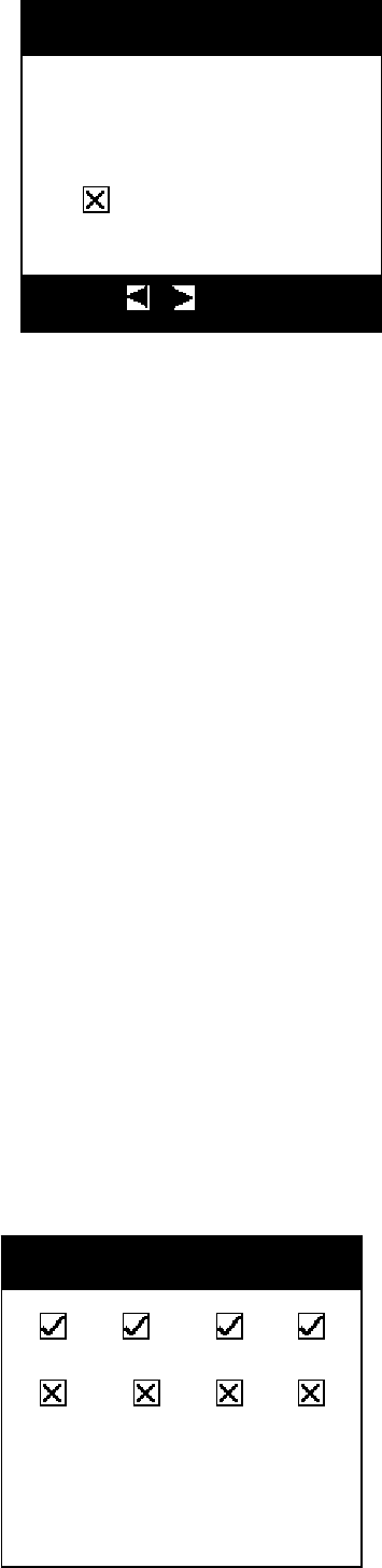
3.4.4.2 Setting Mode
This menu is used to configure the “Door Open Cause”, “Button Buzzer” and “Debug Mode”.
“Door Open Cause” refers to that whether the user selects the “Door Open Cause” (for door
open cause, please refer to “Chapter 4 Key Management”) when the user opens the door to
take the unlocking key; “Button Buzzer” refers to that whether the buzzer is turned on when
the user presses the key; for the “Debug Mode”, if it chooses this feature, the system will
output debug information via the serial debug port, which is mainly used for problem analysis
and positioning in case of abnormality. means such function is not provided, means
:28:39
Fri
2014-05-23
Set time
15
▲ ▼ :Edit
23
such function is provided, currently editing options are highlighted in white.
and keys: Switch the current configuration state of the options;
▲ and ▼ keys: Forward and backward to switch the editing point;
“Esc” key: Cancel the setting and return to the previous menu;
“Enter” key: Save the setting and return to the previous menu;
“Digit” key: no response;
3.4.4.3 Configure Key
Such menu displays after the key management cabinet selects the locking mode (in
Debug - > Operation mode), the menu is used to configure device’s independent locking
function, and the user can only operate the key with unlocking permission. Specific
configuration is as follows:
After the user enters the key permission configuration menu, it can use and
keys to select the user who wants to configure the key permission (consistent with the
browser user interface display), once it is selected, press “Enter” key to enter the
interface below:
1 2 3 4
5 6 7 8
Config Key
Unlock reason
Key beep
Debug mode
Setting
:Edit

24
Note: Key configuration option displays only when locking mode is
configured.
◀ and ▶ keys: Forward and backward to switch the editing point;
▲ and ▼ keys: Switch the current configuration state of the options;
“Enter” key: Change the key permission;
“Esc” key: Prompt whether to save the changed key permission, if it is confirmed to save
the change, it will return to the previous menu, and if it is confirmed not to
save the change, it will return to the previous menu;
3.4.4 System Automatically Shuts Down in the Battery Mode
In the case of battery supply, if the user doesn’t operate the key over one minutes after
the system has returned to the main interface, the system will automatically shut down after
tweeting prompt, so as to save electricity, moreover, it will also automatically shut down in
case of low battery voltage, as shown in the figure below:
▲ ▼:Edit
Main menu
Shutting down...
Please swipe card
25
Chapter 4 Key Management
4.1 Single Authorized Operation Mode
(For the number of the swiping cards, it may be unnecessary for the user to change after it is
configured by the technicians of our company.)
If the number of swiping the cards of the system is 1, as shown in the figure below:
At this moment, the system can only accept one user login, after the user has logged in (for
login, see “3.3 User Login”), it the user doesn’t have operation permission, the interface
prompts as follows:
Press the “Enter” or “Esc” key to return to the main interface of the system, now the
user has logged in and is able to start menu operation, for menu operation, refer to “Chapter 3
Functional Operation of the Management Cabinet”; to press the Esc Key to exit login.
4.1.2 Selection of the Operation Reasons and Key
The device has two modes for key management: Locking Mode and Non-locking
Mode. In the locking mode (requires hardware support), each key can independently lock, the
user can only remove the selected unlocked key, and other keys are in the mandatory locking
UNITECH
2014-05-23
10:18
Please swipe card
No Authorization !
26
state, the user can not remove them; in the non-locking mode, once the door is open, the user
is not limited to take any keys.
4.1.2.1 Locking Mode
In the locking mode, the user must first select the key to be operated, and then select the
operation reasons, the system will unlock the corresponding key, and the user either take
away the key or return the key.
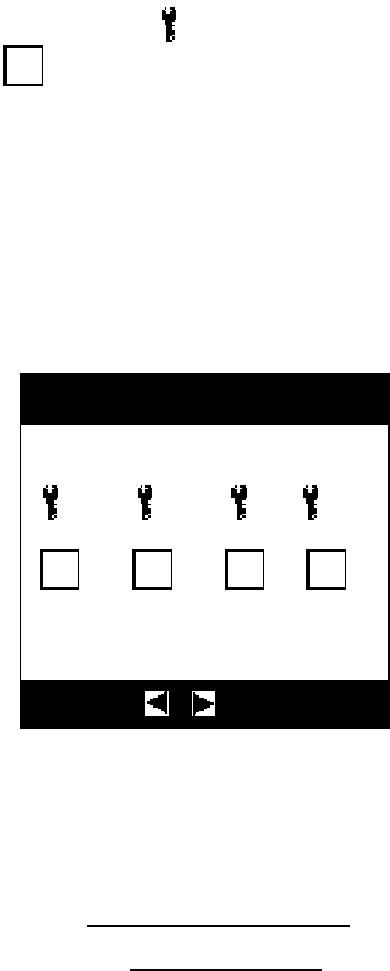
4.1.2.1.1 Select the Key
In the key selection interface, the icon “ ” indicates that the key is in the cabinet of the
management cabinet, while “ ” indicates that the key has been taken away and it is not in
the cabinet. Subscripts 1, 2 and 3 present key positions. Reverse color icon presents the
selected state. The user can use ▲, ▼, and keys to select the key to be operated, press
the “Enter” key for confirmation to enter the next step (the user can only carry out the next
operation of the key with permission, in case of no permission, it will pop up a prompt box
“No permission”). Press the “Esc” key to return to the main interface.
4.1.2.1.2 Select the Operation Reasons
If your system is not equipped with “Select Reason” function, it can skip this
section to directly enter the “4.1.2.1.3 Enter Operation”, for how to configure the
“Select Reason” function, refer to “3.4.4.6 Setup Mode”.
1 2 3 4
5 6 7 8
Please select key
▲ ▼ :switch

27
In case of default, the system has seven selectable operation reasons:
1:Lock fault
2:Maintenance
3:Energency unlock
4:Smart key fault
5:SIS fault
6:Retury key
7:Other reasons
The user can use ▲, ▼, and keys to select the operation reasons, the selected is
highlighted in reverse color. Press the “Enter” key to start operation after selection is made.
4.1.2.1.3 Enter Operation
After entering the operating, the system will automatically unlock the cabinet door
locking mechanism, then the user can open the door to start operating, for locking mode,
the system will unlock the key mechanism corresponding to the card position selected by
the user, the user can either remove or return the key, but other keys in their places are
still in the locking mode, the user can not operate them; for non-locking mode, which
key will be removed by the user is not limited by the constraint locking of the system.
After the operation, when placing the key back, if it displays a prompt box on the
interface with buzzing, e.g. the management cabinet displays a prompt box below:
01:Lock fault
02:Maintenance
03:Energency unlock
04:Smart key fault
05: SIS fault
06:Retury key
Select unlock reason
▲ ▼ :switch

28
Prompt interface of the management cabinet is as follows:
According to prompt, the user should insert the wrongly inserted key back into the
correct position.
4.1.2.2 Non-locking Mode
In the non-locking mode, the user must first select the operation reason (for how to select
the operation reasons, please refer to “4.1.2.1.2 Select the Operation Reasons”), then the
device will automatically unlock the door, and the user can take the key now. Users do not
have to select a key in non-locking mode.
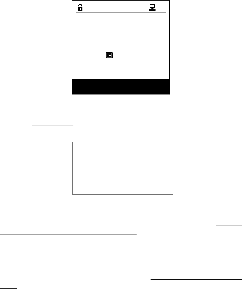
4.1.3 U Disk Authorization
。
If the system is not equipped with U-Key mode, skip this section, and go directly to
“4.1.2 Select the Operation Reasons and Key”.
When the system is equipped with the U-Key mode, as shown in the figure below:
Have no
this key!
Position 3
back to 2!
29
Before U disk is inserted to open the door, the system will verify the inserted U disk, if
the inserted U disk is not registered with the support PC or doesn’t have the operating
permission of the management cabinet, it will prompt as follows. Press the “Enter” or “Esc”
key to return to the main interface:
After successful verification, refer to “4.1.2 Select the Operational Reasons and Key”,
after the operation is completed, closing the door will save the operation records in the U
disk that shall be removed after saving, at this moment, the user exits the locking mode of
the management cabinet, and the user may insert the U disk into the host to upload the
record to the host computer and display. Prompt is as follows:
请插入 U盘开门
UNITECH
2014-05-23
10:18
Please insert U-Key!
The U-Key Has
No Auth!
U-Key User can
Not Operate In
Current State!
Saving records
do not remove
the U-Key!
30
4.1.4 Network Authorization
If the system is not equipped with network authorization, skip this section, and go
directly to “4.1.2 Select the Operational Reasons and Key”.
When the system is equipped with network authorization, after the user has logged in
the website, it can directly unlock the management cabinet’s door as well as the key.
4.2 Double Authorization Operation Mode
(For the number of the swiping cards, it may be unnecessary for the user to change
after it is configured by the technicians of our company.)
4.2.1 Non-locking Mode
In the non-locking mode, when the swiping number of the system is 2, it can start
operation only after the two users have logged in, but user’s login mode is not limited,
both password and card swiping login can do, once one user has logged in, it will display
“For operation, please swipe the second card’, as shown in the figure below:
UNITECH
2014-05-23
10:18
Please swipe the
second card
Records saved!

31
Note: The login user must have an operating permission while the other
should have an authorized permission.
a) If the user has no operating permission, the interface prompts as follows:
Press the “Enter” or “Esc” key to return to the main interface of the system, the user has
logged in and can start menu operation, for menu operation, refer to the “3.4 Menu
Operation”.
b) When one user has operating permission, but the other has no authorized permission,
the system prompts as follows:
Press the “Enter” or “Esc” key to return to the main interface of the system, the user has
logged in and can start menu operation, for menu operation, refer to the “Chapter 3
Functional Operation of the Management Cabinet
c) When one user has operating permission, but the other has authorized permission,
then it will be deemed that this operation is authorized, if door-open reason is provided, it
will enter the “select the operating reasons and the key” process that is the same as that
equipped with card number 1, for specific details, refer to “4.1.2 Select the Operation
Reasons and Key”, so it is not reiterated here.
4.2.2 Locking Mode
In the locking mode, when the card swiping number of the system is 2, it requires
No Authorization !
Unauthorized User !
32
the user to select the authorization mode (authorization modes depend on the
configuration in the operation mode), such as for selecting the network authorization, it
should swipe the first card to open the door, and then enter the interface for selecting
authorization mode:
Authorization modes have two kinds: card swiping authorization and network
authorization, of which card swiping authorization is a basic authorization, other
authorization will become valid only appropriate authorization is selected. The table
below shows the authorization mode corresponding to the relevant option
configured in the UT-059B operation mode:
Card swiping
authorization
Network
authorization
Swiping card number √
Network mode √ √
After the user has selected the authorization mode, it displays key selection
interface:
Swipe mode
Net mode
Select Mode
:switch
Key #4
01 02 03 04
You selected 4 key
Please select key
04
▲ ▼:Edit

33
◀ and ▶ keys: Forward and backward to switch the editing point;
▲ and▼ keys: Function keys, represents whether it is selected, and an appropriate key is
selected;
“Enter” key: Prompt whether it needs to save the key number that needs to apply for
unlocking;
“Digit” key: Response, when the entering is beyond the limit, it displays user’s first key
number with the unlocking permission;
“Esc” key: Prompt whether to exit from this interface, it is verified to return to the main
interface, if not, it will not exit.
a)Card Swiping authorization
In the card swiping authorization mode, after the key to be applied for unlocking is selected,
it enters the main interface to wait for other users to have card swiping authorization, and similar
to unlocking in the non-locking mode, it may refer to “4.2.1 Non-locking Mode”, so it is not
reiterated here.
b) Network authorization
In the network authorization mode, if the key to be applied for unlocking is selected, and hen
press the “Ok” key, it will display “Network application for unlocking key information has been
sent, please wait ...”, if the network communication failed, it will prompt “Network not connected,
please check ... ”.
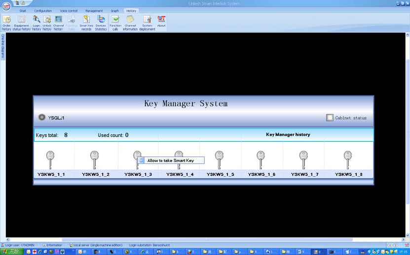
It shall click the corresponding key card position to unlock on the key management system
interface.
34
Note: If the principal computer successfully communicates with the management cabinet, the
small dot on the upper left corner shown in the figure becomes red, otherwise it is gray.
4.3 Multiplayer Authorization Operation Mode
For a system equipped with a swiping card number of 3, in addition it can be
operated only after three users have logged in, other conditions and configurations are
the same as those of the swiping card number of 2, so it is not reiterated here.
4.5 Operation in Case of Emergency
In case of emergency, door shall be removable, and the specific methods are as
follows:
a) Insert the tip of a sharp tool into the bottom gap of the management cabinet glass
window to pry it open with tilt force.
b) Remove the glass window and take the desired key.
c) After completion of using the key, re-swipe the card to open the door, press the
pin at the bottom of the inner side of the cabinet door to install the door slowly with
force.

35
Chapter 5 Remedy of the Common Problems
No. Symptom Cause Remedy
1
No start when
pressing the power
b
utton in the case of
an external power
failure
Backup rechargeable battery is
exhausted, no electricity
Recharge the battery after the external
power is restored
2
3
4