Zhuhai Unitech Power Technology WJBS7E-2HC Transmission Adaptor User Manual
Zhuhai Unitech Power Technology Co., Ltd. Transmission Adaptor Users Manual
Users Manual

1
Document No.: UM- WJBS7E_2HC -001
Version No.: V1.0
WJBS-7E_2HC
Transmission Adaptor
Instruction manual
Compiler: Liang Jiawen, Yang Shaohua, Zhang Qian
Approved by: Yang Shaohua Li Baofu
Reviewed by: Yu Yongqiang
Countersigned by: Mo Yiting
Zhuhai UNITECH Power Technology Co., Ltd.
March 10, 2014

ii
Revision History
Date Version Summary of Revision Revised by Approved
by
2014-03-10 V1.0 Initial version Yang
Shaohua Li Baofu
i
Contents
CHAPTER 1 GENERAL DESCRIPTION ................................................................ 1
1.1.Overview ............................................................................................................................................ 1
1.2. FCC Statement ................................................................................................................................. 1
CHAPTER 2 APPEARANCE ..................................................................................... 2
CHAPTER 3 DESCRIPTION OF INTERFACES AND INDICATORS ................ 3
3.1. Description of External Interfaces ................................................................................................. 3
3.2.Description of Indicators .................................................................................................................. 4
CHAPTER 4 INSTRUCTIONS .................................................................................. 7
4.1. Charge .............................................................................................................................................. 7
4.2. Data Transmission ........................................................................................................................... 7
4.3. GUI Display and Operations .......................................................................................................... 7
1
Chapter 1 General Description
1.1. Overview
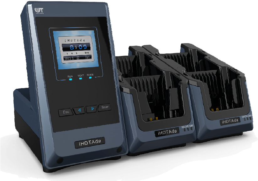
The WJBS-7E_2HC Transmission Adaptor can be configured with some slave machines flexibly (one host machine
supports up to five slave machines), and the handheld devices supported by each slave machine can be
independently configured to meet different requirements on site. Between the WJBS-7E_2HC Transmission Adaptor
and the upper computer, multiple communication interfaces are supported, including: serial, USB (2.0 full speed),
and Ethernet (supporting simultaneous communication of up to four ports). Between the WJBS-7E_2HC
Transmission Adaptor and a handheld device, the infrared communication interface (IrDA) is supported. The
JBS-7E_2HC Transmission Adaptor uses a TFT 65,536 Color LCD and a 4-button simple style, the man-machine
interface is friendly and easy to operate, and it displays an accurate calendar.
1.2. FCC Caution
§ 15.19 Labelling requirements.
This device complies with part 15 of the FCC Rules. Operation is subject to the following two
conditions: (1) This device may not cause harmful interference, and (2) this device must accept any
interference received, including interference that may cause undesired operation.
§ 15.21 Information to user.
Any Changes or modifications not expressly approved by the party responsible for compliance could
void the user's authority to operate the equipment.
§ 15.105 Information to the user.
Note: This equipment has been tested and found to comply with the limits for a Class B digital device,
pursuant to part 15 of the FCC Rules. These limits are designed to provide reasonable protection
against harmful interference in a residential installation. This equipment generates uses and can
radiate radio frequency energy and, if not installed and used in accordance with the instructions, may
cause harmful interference to radio communications. However, there is no guarantee that
interference will not occur in a particular installation. If this equipment does cause harmful
interference to radio or television reception, which can be determined by turning the equipment off
and on, the user is encouraged to try to correct the interference by one or more of the following
measures:
-Reorient or relocate the receiving antenna.
-Increase the separation between theequipment and receiver.
-Connect the equipment into an outlet on a circuit different from that to which the receiver is
connected.
-Consult the dealer or an experienced radio/TV technician for help.
2
Chapter 2 Appearance
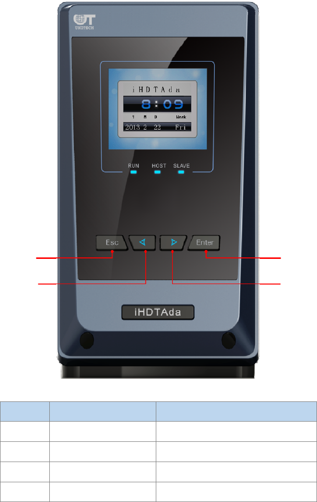
Front view:
The buttons on the host machine are described as follows:
3
No. Button Definition Function
1 ESC Exit
2 < Select (left)
3 > Select (right)
4 Enter Confirm
Chapter 3 Description of Interfaces and Indicators
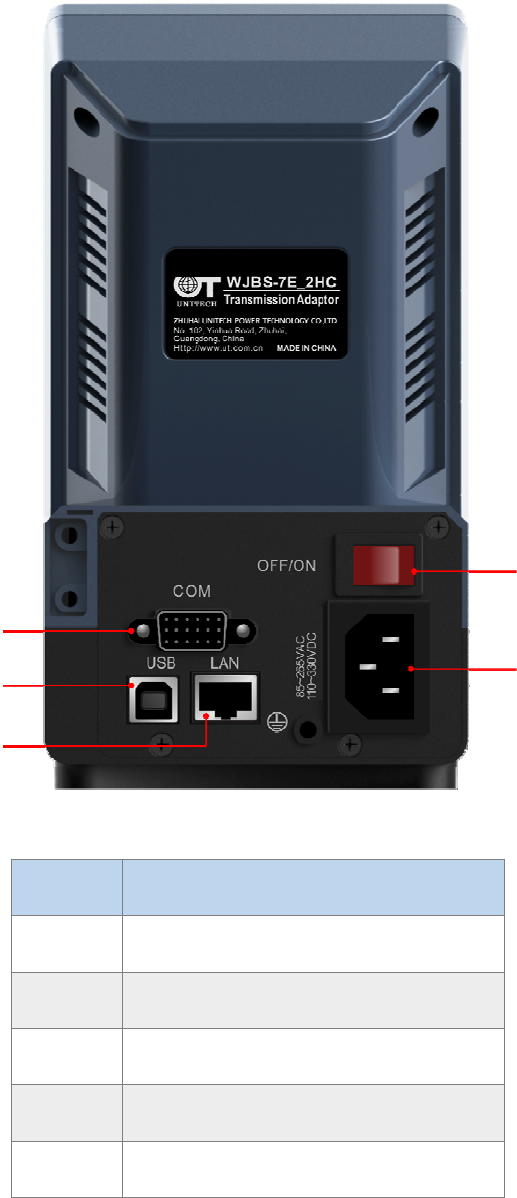
3.1. Description of External Interfaces
The rear view of the host machine is as shown below:
1
2
4
3
4
No. Function
1 OFF/ON power switch
2 External power supply interface
3 USB interface
4 RS232 interface
5 Ethernet interface
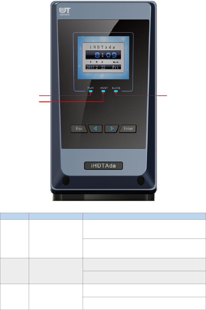
3.2. Description of Indicators
The indicators on the host machine panel are described as follows:
1
2
5
3
4
5
No. Indicator Definition Function
1 RUN
It quickly flashes twice every 3 seconds: This
indicates that the host machine is in BOOT status
(for software upgrade and factory configuration).
It quickly flashes once every 3 seconds: This
indicates that the host machine is in APP status
(normal operation status).
2 HOST
The red light flashes: This indicates that the host
machine is receiving data from the upper computer.
The green light flashes: This indicates that the host
machine is sending data to the upper computer.
3 SLAVE
The red light flashes: This indicates that the host
machine is receiving data from a slave machine.
The green light flashes: This indicates that the host
machine is sending data to a slave machine.
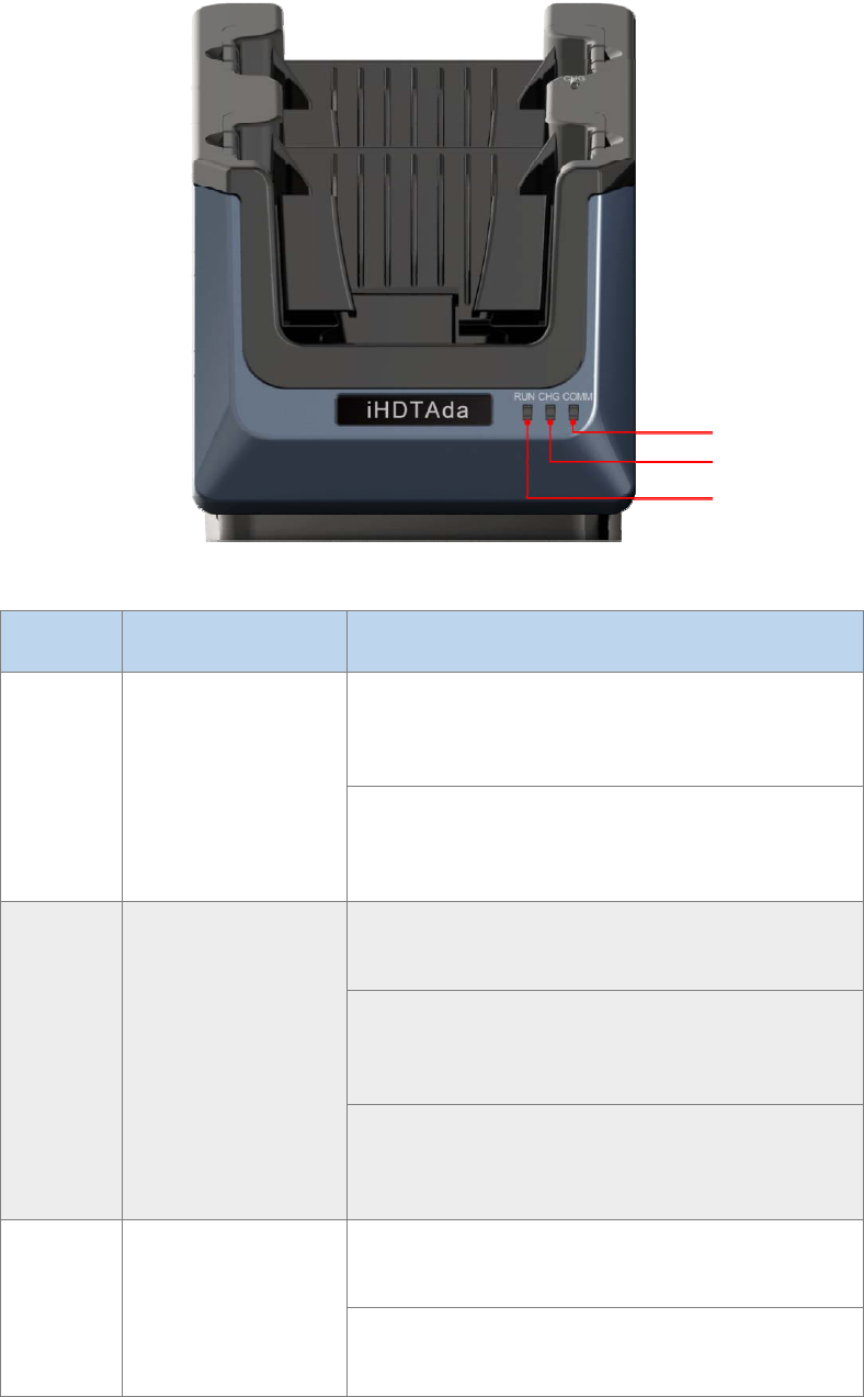
The indicators on a slave machine are described as follows:
1
2
3
6
No. Indicator Definition Function
1 RUN
It quickly flashes three times every 3 seconds: This
indicates that the slave machine is in BOOT status
(for software upgrade only).
It quickly flashes once every 1 second: This indicates
that the slave machine is in APP status (normal
operation status).
2 CHG
The light is off: This indicates that there is no
handheld device in the slave machine.
The red light is always on: This indicates that the
handheld device in the slave machine is placed
incorrectly.
The green light is always on: This indicates that the
handheld device in the slave machine is placed
properly.
3 COMM
The red light flashes: This indicates that the slave
machine is receiving data from the host machine.
The green light flashes: This indicates that the slave
machine is sending data to the host machine.
3
2
1

7
Chapter 4 Instructions
4.1. Charge
After the WJBS-7E_2HC Transmission Adaptor is connected to the power supply, a Smart Key can be placed in a
holder of a slave machine for automatic charging. The charging progress can be seen from the display of the Smart
Key.
4.2. Data Transmission
The WJBS-7E_2HC Transmission Adaptor is connected to the upper computer through RS232, USB, or Ethernet,
and transfers the data of the upper computer to the Smart Key through the infrared interface at the bottom of the
slave machine.
4.3. GUI Display and Operations
(Standby Interface)
After the WJBS-7E_2HC Transmission Adaptor is powered on or enters the idle status, the standby interface is
displayed, to enter the main menu interface, press all the four buttons simultaneously in standby status.
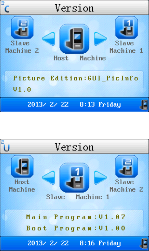
4.3.1 View the software version:
After the adapter is powered on and enters normal operation mode, select "Help"→"Version", as shown below:
8
(View the version information of the host machine's main program and BOOT program)
(View the version information of the slave machine's main program and BOOT program)
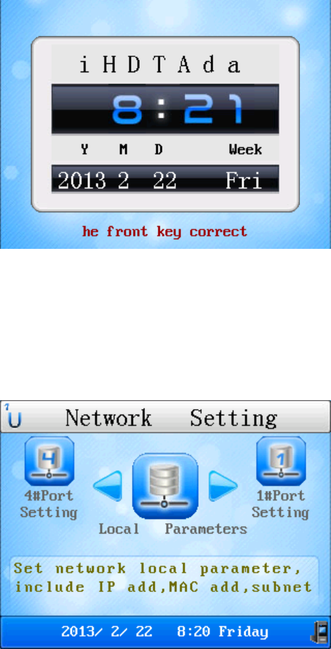
4.3.2 A prompt is cyclically displayed when the key is placed incorrectly:
When the key is placed incorrectly, the buzzer generates a warning every 30 seconds, and the prompt "Please place
the front (rear) key correctly" is displayed cyclically on the host machine's LCD.
9
(Cyclically displayed prompt "Please place the front key correctly")
4.3.3 NIC configuration:
(Note: After the NIC configuration is modified, you need to restart the machine to make the new configuration
valid.)
(Configure NIC basic parameters and four ports)
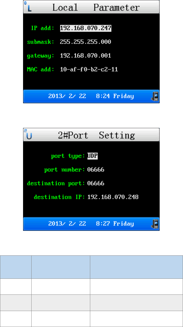
10
(Configure the local parameters, pressing Left/Right for selection and pressing Enter for revision)
(Configure the port parameters, pressing Left/Right for selection and pressing Enter for revision)
No. Configuration
Option Function
1 Port number Port number of the adapter
2 Destination port Port number of the upper computer
3 Destination IP IP address of the upper computer
4.3.4 Set the system time:

11
(Set the system time of the machine, pressing Left/Right for selection, pressing Enter for revision, and pressing ESC
for saving and exiting)
4.3.5 Set the brightness of the backlight:
(Set the brightness of the backlight, pressing Left/Right for adjustment (range: 1-8) and pressing Enter or ESC for
saving and exiting)
4.3.6 Change the background:
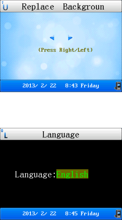
12
(Set the background, pressing Left/Right for selection and pressing Enter or ESC for saving and exiting)
4.3.7 Set the language:
(Set the language, pressing Left/Right for selection and pressing Enter or ESC for saving and exiting)
4.3.8 Communication interface:
The WJBS-7E_2HC Transmission Adaptor supports simultaneous communication of up to four slave machines, if
more than 4 slave machines communicate simultaneously, the last slave machine shall wait until the previous one
ends communication.
The buttons become invalid during communication. Simultaneous communication of four slave machines is as
shown below:
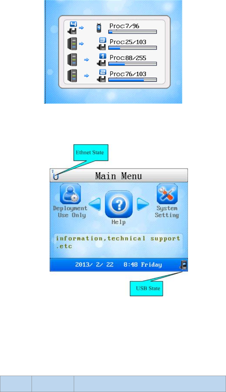
13
(The WJBS-7E_2HC Transmission Adaptor supports simultaneous communication of up to four slave machines)
4.3.9 Main Interface:
Description of main interface icons
● Description of Ethernet state icon (Take port 0 as an example, the icon is the same for the other ports.)
This icon cyclically displays the current status of each of the four Ethernet ports, the icon for each status is
described as follows:
No. Icon Function
14
1
The port is not enabled.
2
The TCP connection of the port is disconnected.
3
The port is in transition status, and does not respond to TCP
connection requests.
4
The port is in Server mode and listening to the Client end,
in this case, it can respond to TCP connection requests.
5
The TCP connection of the port is established successfully,
and data transmission is ready.
6
The port is in UDP status, and data transmission is ready.
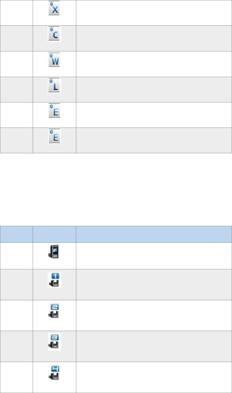
● Description of USB connection status icon
This icon indicates the physical connection status of the internal circuit of the USB port at the back of the host
machine, the icon for each status is described as follows:
No. Icon Function
1
The internal USB circuit is connected to the host machine.
2
The internal USB circuit is connected to the handheld
device in slave machine 1, that means, this handheld device
is directly connected to the computer through a USB cable.
3
The internal USB circuit is connected to the handheld
device in slave machine 2, that means, this handheld device
is directly connected to the computer through a USB cable.
4
The internal USB circuit is connected to the handheld
device in slave machine 3, that means, this handheld device
is directly connected to the computer through a USB cable.
5
The internal USB circuit is connected to the handheld
device in slave machine 4, that means, this handheld device
is directly connected to the computer through a USB cable.

15
6
The internal USB circuit is connected to the handheld
device in slave machine 5, that means, this handheld device
is directly connected to the computer through a USB cable.
7 (No icon) The internal USB circuit is disconnected.