Ziehl Abegg SE EMW RF Module MOSI09B User Manual
Ziehl-Abegg AG RF Module MOSI09B Users Manual
Contents
- 1. Installation Instruction
- 2. Operating Instruction
Operating Instruction
AM-PREMIUM / AM-PREMIUM-W
Part.-No. 349046 / 349051
Universal control module for ECblue fans
Operating Instructions
Software version: D1727A / D2263A from version 4.00
L-BAL-E095-GB 1203 Index 004 Part.-No.
english

Content
1 General notes . . . . . . . . . . . . . . . . . . . . . . . . . . . . . . . . . . . . . . . . . . . . . . . . . . . . . . . . . . . . . 5
1.1 Structure of the operating instructions . . . . . . . . . . . . . . . . . . . . . . . . . . . . . . . . . . . . . 5
1.2 Exclusion of liability . . . . . . . . . . . . . . . . . . . . . . . . . . . . . . . . . . . . . . . . . . . . . . . . . . . 5
2 Safety instructions . . . . . . . . . . . . . . . . . . . . . . . . . . . . . . . . . . . . . . . . . . . . . . . . . . . . . . . . . 5
3 General description . . . . . . . . . . . . . . . . . . . . . . . . . . . . . . . . . . . . . . . . . . . . . . . . . . . . . . . . 5
3.1 Operational area . . . . . . . . . . . . . . . . . . . . . . . . . . . . . . . . . . . . . . . . . . . . . . . . . . . . . . 5
3.2 Function . . . . . . . . . . . . . . . . . . . . . . . . . . . . . . . . . . . . . . . . . . . . . . . . . . . . . . . . . . . . 5
3.3 Transport . . . . . . . . . . . . . . . . . . . . . . . . . . . . . . . . . . . . . . . . . . . . . . . . . . . . . . . . . . . 5
3.4 Storage . . . . . . . . . . . . . . . . . . . . . . . . . . . . . . . . . . . . . . . . . . . . . . . . . . . . . . . . . . . . . 5
3.5 Disposal / recycling . . . . . . . . . . . . . . . . . . . . . . . . . . . . . . . . . . . . . . . . . . . . . . . . . . . 5
4 Mounting . . . . . . . . . . . . . . . . . . . . . . . . . . . . . . . . . . . . . . . . . . . . . . . . . . . . . . . . . . . . . . . . . 6
5 Electrical installation . . . . . . . . . . . . . . . . . . . . . . . . . . . . . . . . . . . . . . . . . . . . . . . . . . . . . . . 7
5.1 Safety precautions . . . . . . . . . . . . . . . . . . . . . . . . . . . . . . . . . . . . . . . . . . . . . . . . . . . . 7
5.2 Signal connection or sensor connection to analog inputs (Analog In 2, Analog In 3) . . 7
5.3 Output voltage 0 - 10 V (Analog Out) . . . . . . . . . . . . . . . . . . . . . . . . . . . . . . . . . . . . . . 7
5.4 Voltage supply for external devices (+24V, GND) . . . . . . . . . . . . . . . . . . . . . . . . . . . . . 7
5.5 Connection external terminal type A-G-247NW or AXG-1A(E) . . . . . . . . . . . . . . . . . . . 8
5.6 Digital inputs (D1, E1 = D2) . . . . . . . . . . . . . . . . . . . . . . . . . . . . . . . . . . . . . . . . . . . . . 9
5.7 Relay output (K1) . . . . . . . . . . . . . . . . . . . . . . . . . . . . . . . . . . . . . . . . . . . . . . . . . . . . . 9
5.8 Communication . . . . . . . . . . . . . . . . . . . . . . . . . . . . . . . . . . . . . . . . . . . . . . . . . . . . . . . 9
5.8.1 Networking via MODBUS-RTU . . . . . . . . . . . . . . . . . . . . . . . . . . . . . . . . . . . . . . 9
5.8.2 RS-485 - network design and interface parameter . . . . . . . . . . . . . . . . . . . . . . . . 9
5.8.3 AM-PREMIUM-W Wireless Communication . . . . . . . . . . . . . . . . . . . . . . . . . . . . . 11
5.9 Potential at control voltage connections . . . . . . . . . . . . . . . . . . . . . . . . . . . . . . . . . . . . 11
6 Operating by terminal . . . . . . . . . . . . . . . . . . . . . . . . . . . . . . . . . . . . . . . . . . . . . . . . . . . . . . 12
6.1 Hand held terminal type A-G-247-NW for several members . . . . . . . . . . . . . . . . . . . . . 12
6.1.1 Display and operating elements of the terminal . . . . . . . . . . . . . . . . . . . . . . . . . . 12
6.1.2 Establish connection to member . . . . . . . . . . . . . . . . . . . . . . . . . . . . . . . . . . . . . 13
6.2 Terminal type AXG-1A(E) for one member . . . . . . . . . . . . . . . . . . . . . . . . . . . . . . . . . . 14
6.3 Menu operation . . . . . . . . . . . . . . . . . . . . . . . . . . . . . . . . . . . . . . . . . . . . . . . . . . . . . . 14
6.4 Menu structure . . . . . . . . . . . . . . . . . . . . . . . . . . . . . . . . . . . . . . . . . . . . . . . . . . . . . . . 15
6.5 Example for programming mode 2.01 in “Base setup” . . . . . . . . . . . . . . . . . . . . . . . . 15
7 Base setup . . . . . . . . . . . . . . . . . . . . . . . . . . . . . . . . . . . . . . . . . . . . . . . . . . . . . . . . . . . . . . . 16
7.1 Select operation mode . . . . . . . . . . . . . . . . . . . . . . . . . . . . . . . . . . . . . . . . . . . . . . . . . 16
7.2 External Setpoint / External speed setting in manual operation . . . . . . . . . . . . . . . . . . 17
8 Start-up . . . . . . . . . . . . . . . . . . . . . . . . . . . . . . . . . . . . . . . . . . . . . . . . . . . . . . . . . . . . . . . . . . 18
8.1 Prerequisites for commissioning . . . . . . . . . . . . . . . . . . . . . . . . . . . . . . . . . . . . . . . . . . 18
8.2 Procedure for commissioning . . . . . . . . . . . . . . . . . . . . . . . . . . . . . . . . . . . . . . . . . . . . 18
8.3 Menu Mode 1.01 . . . . . . . . . . . . . . . . . . . . . . . . . . . . . . . . . . . . . . . . . . . . . . . . . . . . . 18
9 Programming . . . . . . . . . . . . . . . . . . . . . . . . . . . . . . . . . . . . . . . . . . . . . . . . . . . . . . . . . . . . . 19
9.1 Speed controller 1.01 . . . . . . . . . . . . . . . . . . . . . . . . . . . . . . . . . . . . . . . . . . . . . . . . . 19
9.1.1 Base setup 1.01 ............................................... 19
9.1.2 Setting for operation 1.01 ......................................... 19
9.2 Temperature control 2.01 ... 2.05 . . . . . . . . . . . . . . . . . . . . . . . . . . . . . . . . . . . . . . . . . 20
9.2.1 Basic setting 2.01 ... 2.05 ......................................... 20
9.2.2 Settings for operation modes 2.01 ... 2.05 . . . . . . . . . . . . . . . . . . . . . . . . . . . . . 21
9.2.3 Functional diagrams temperature control . . . . . . . . . . . . . . . . . . . . . . . . . . . . . . . 22
Operating Instructions AM-PREMIUM / AM-PREMIUM-W – model series
L-BAL-E095-GB 1203 Index 004 Part.-No.
2/68

9.2.4 Additional for mode 2.03 : Signal output 0 - 10 V . . . . . . . . . . . . . . . . . . . . . . . . . 23
9.2.5 For mode 2.03 : Relay output for Heating or Cooling . . . . . . . . . . . . . . . . . . . . . . 24
9.2.6 For mode 2.03 Relay output for temperature monitoring . . . . . . . . . . . . . . . . . . . . 25
9.3 Pressure control for condensers refrigeration 3.01 ... 3.04 . . . . . . . . . . . . . . . . . . . . . 26
9.3.1 Base setup 3.01 ... 3.04 .......................................... 26
9.3.2 Setting for operation modes 3.01 ... 3.02 .............................. 27
9.3.3 Functional diagrams pressure control condensers . . . . . . . . . . . . . . . . . . . . . . . . . 28
9.4 Pressure control airconditioning 4.01 ... 4.03 . . . . . . . . . . . . . . . . . . . . . . . . . . . . . . . 29
9.4.1 Base setup 4.01 ... 4.03 .......................................... 29
9.4.2 Setting for operation modes 4.01 ... 4.03 .............................. 30
9.5 Volume control 5.01 ... 5.02 . . . . . . . . . . . . . . . . . . . . . . . . . . . . . . . . . . . . . . . . . . . . . 32
9.5.1 Basic setting 5.01 and 5.02 ....................................... 32
9.5.2 Setting for operation modes 5.01 ... 5.02 ............................... 32
9.6 Air velocity control 6.01 . . . . . . . . . . . . . . . . . . . . . . . . . . . . . . . . . . . . . . . . . . . . . . . . 34
9.6.1 Base setup 6.01 ............................................... 34
9.6.2 Settings for operation modes 6.01 ................................... 35
9.7 Menu group Start . . . . . . . . . . . . . . . . . . . . . . . . . . . . . . . . . . . . . . . . . . . . . . . . . . . . . 36
9.8 Menu group Info . . . . . . . . . . . . . . . . . . . . . . . . . . . . . . . . . . . . . . . . . . . . . . . . . . . . . . 37
9.9 Controller Setup . . . . . . . . . . . . . . . . . . . . . . . . . . . . . . . . . . . . . . . . . . . . . . . . . . . . . . 38
9.9.1 PIN protection activate, PIN 0010 . . . . . . . . . . . . . . . . . . . . . . . . . . . . . . . . . . . . 38
9.9.2 PIN protection activate, PIN 1234 . . . . . . . . . . . . . . . . . . . . . . . . . . . . . . . . . . . . 38
9.9.3 Save user settings restore with PIN 9090 . . . . . . . . . . . . . . . . . . . . . . . . . . . . . . 38
9.9.4 Sensor Alarm ON / OFF . . . . . . . . . . . . . . . . . . . . . . . . . . . . . . . . . . . . . . . . . . 38
9.9.5 Limit . . . . . . . . . . . . . . . . . . . . . . . . . . . . . . . . . . . . . . . . . . . . . . . . . . . . . . . . 39
9.9.6 Minimum speed cut off . . . . . . . . . . . . . . . . . . . . . . . . . . . . . . . . . . . . . . . . . . . 39
9.9.7 Second Group . . . . . . . . . . . . . . . . . . . . . . . . . . . . . . . . . . . . . . . . . . . . . . . . . 40
9.9.8 Reverse action of the control function . . . . . . . . . . . . . . . . . . . . . . . . . . . . . . . . . 40
9.9.9 Controller configuration . . . . . . . . . . . . . . . . . . . . . . . . . . . . . . . . . . . . . . . . . . . 41
9.9.10 Data on the total control deviation . . . . . . . . . . . . . . . . . . . . . . . . . . . . . . . . . . . 41
9.9.11 LED Mode . . . . . . . . . . . . . . . . . . . . . . . . . . . . . . . . . . . . . . . . . . . . . . . . . . . . 41
9.10 IO Setup . . . . . . . . . . . . . . . . . . . . . . . . . . . . . . . . . . . . . . . . . . . . . . . . . . . . . . . . . . . . 42
9.10.1 Analog-Output “A” ............................................... 42
9.10.2 Digital inputs “D1” / “D2” (E1) . . . . . . . . . . . . . . . . . . . . . . . . . . . . . . . . . . . . . . 43
9.10.2.1 Menu overview . . . . . . . . . . . . . . . . . . . . . . . . . . . . . . . . . . . . . . . . 43
9.10.2.2 Enable ON/OFF function
|
1D
|
. . . . . . . . . . . . . . . . . . . . . . . . . . . . . 44
9.10.2.3 External fault Function
|
2D
|
............................... 44
9.10.2.4 Limit ON / OFF, Function
|
3D
|
. . . . . . . . . . . . . . . . . . . . . . . . . . . . . 45
9.10.2.5 Switch over Input signal “E2” / “E3”, Function
|
4D
|
. . . . . . . . . . . . . . . 45
9.10.2.6 Set 1/2 or Setpoint 1/2, Function
|
5D
|
. . . . . . . . . . . . . . . . . . . . . . . . 45
9.10.2.7 Intern / Extern Function
|
6D
|
.............................. 46
9.10.2.8 Automatic control / speed manual, Function
|
7D
|
(mode 2.01 ) . . . . . . . 47
9.10.2.9 Reverse action of control function ( 2.01 ), Function
|
8D
|
. . . . . . . . . . . 47
9.10.2.10 Reset, Function
|
10D
|
................................... 47
9.10.2.11 Setting Max. Speed ON / OFF function
|
11D
|
. . . . . . . . . . . . . . . . . . . 48
9.10.2.12 Direction of rotation, Function
|
13D
|
. . . . . . . . . . . . . . . . . . . . . . . . . 48
9.10.2.13 “Freeze function” = maintain momentary modulation value, Function
|
14D
|
48
9.10.3 Configuration of analog inputs “E1”and “E3” . . . . . . . . . . . . . . . . . . . . . . . . . . . . . 49
9.10.3.1 Signal adaption E2 and E3 . . . . . . . . . . . . . . . . . . . . . . . . . . . . . . . . 49
9.10.3.2 Inverting analog inputs “E2” / “E3” . . . . . . . . . . . . . . . . . . . . . . . . . . . 50
9.10.4 Function and inverting for relay outputs “K1” ............................ 51
9.10.5 Networking via MODBUS . . . . . . . . . . . . . . . . . . . . . . . . . . . . . . . . . . . . . . . . . 52
9.11 Limits . . . . . . . . . . . . . . . . . . . . . . . . . . . . . . . . . . . . . . . . . . . . . . . . . . . . . . . . . . . . . . 52
9.11.1 Limit indication depending on modulation . . . . . . . . . . . . . . . . . . . . . . . . . . . . . . 53
9.11.2 Limit indication depending on setting or sensor signal . . . . . . . . . . . . . . . . . . . . . . 53
9.11.3 Limit indication depending on (offset) to Setpoint . . . . . . . . . . . . . . . . . . . . . . . . . 55
9.12 Motor Setup . . . . . . . . . . . . . . . . . . . . . . . . . . . . . . . . . . . . . . . . . . . . . . . . . . . . . . . . . 56
9.12.1 Setting for Rampup time and Rampdown time . . . . . . . . . . . . . . . . . . . . . . . . . . . 56
9.12.2 Suppression of speeds . . . . . . . . . . . . . . . . . . . . . . . . . . . . . . . . . . . . . . . . . . . 57
Operating Instructions AM-PREMIUM / AM-PREMIUM-W – model series
L-BAL-E095-GB 1203 Index 004 Part.-No.
3/68

10 Menu tables . . . . . . . . . . . . . . . . . . . . . . . . . . . . . . . . . . . . . . . . . . . . . . . . . . . . . . . . . . . . . . 58
10.1 Menues of operating modes . . . . . . . . . . . . . . . . . . . . . . . . . . . . . . . . . . . . . . . . . . . . . 58
10.2 Possible allocation of the IOs, PINs . . . . . . . . . . . . . . . . . . . . . . . . . . . . . . . . . . . . . . . 62
11 Diagnostics menu . . . . . . . . . . . . . . . . . . . . . . . . . . . . . . . . . . . . . . . . . . . . . . . . . . . . . . . . . 65
12 Enclosure . . . . . . . . . . . . . . . . . . . . . . . . . . . . . . . . . . . . . . . . . . . . . . . . . . . . . . . . . . . . . . . . 66
12.1 Connection diagram . . . . . . . . . . . . . . . . . . . . . . . . . . . . . . . . . . . . . . . . . . . . . . . . . . . 66
12.2 Index . . . . . . . . . . . . . . . . . . . . . . . . . . . . . . . . . . . . . . . . . . . . . . . . . . . . . . . . . . . . . . 67
12.3 Manufacturer reference . . . . . . . . . . . . . . . . . . . . . . . . . . . . . . . . . . . . . . . . . . . . . . . . 68
12.4 Service information . . . . . . . . . . . . . . . . . . . . . . . . . . . . . . . . . . . . . . . . . . . . . . . . . . . . 68
Operating Instructions AM-PREMIUM / AM-PREMIUM-W – model series
L-BAL-E095-GB 1203 Index 004 Part.-No.
4/68

1.3 FCC / IC Statements
FCC Compliance (US)
This device complies with Part 15 of the FCC Rules. Operation is subject to the following
two conditions: (1) this device may not cause harmful interference, and (2) this device must
accept any interference received, including interference that may cause undesired
operation.
Note: This equipment has been tested band found to comply with the limits for a Class A
digital device, pursuant to part 15 of the FCC Rules. These limits are designed to provide
reasonable protection against harmful interference when the equipment is operated in a
commercial environment. This equipment generates, uses, and can radiate radio frequency
energy and, if not installed and used in accordance with the instruction manual, may cause
harmful interference to radio communications. Operation of this equipment in a residential
area is likely to cause harmful interference in which case the user will be required to correct
the interference at his own expense.
FCC Warning
Changes or modifications not expressly approved by the party responsible for compliance
could void the user's authority to operate the equipment.
IC Compliance (Canada)
This device complies with Industry Canada licence-exempt RSS standard(s). Operation is
subject to the following two conditions: (1) this device may not cause interference, and (2)
this device must accept any interference, including interference that may cause undesired
operation of the device.
Le présent appareil est conforme aux CNR d'Industrie Canada applicables aux appareils
radio exempts de licence. L'exploitation est autorisée aux deux conditions suivantes : (1)
l'appareil ne doit pas produire de brouillage, et (2) l'utilisateur de l'appareil doit accepter
tout brouillage radioélectrique subi, même si le brouillage est susceptible d'en
compromettre le fonctionnement.
This Class A digital apparatus complies with Canadian ICES-003.
Cet appareil numérique de la classe A est conforme à la norme NMB-003 du Canada.
(for AM-PREMIUM-W Modules only)
The FCC / IC warnings and statements are valid only for the AM-PREMIUM-W modules,
because they have only installed the integrated submodule EM-W, that enhances the AM-
PREMIUM module with the radio communication function to allow communication over
radio frequencies with other Ziehl-Abegg devices (only).
Note: Only the submodule EM-W installed in the AM-PREMIUM-W module is tested for
compliancy according to the relevant FCC and IC standards (for more information see
installation instruction of EM-W).

Note: The AM-PREMIUM-W module is strictly limited for the integration
and usage in host devices (fans and converters) of Ziehl-Abegg AG.
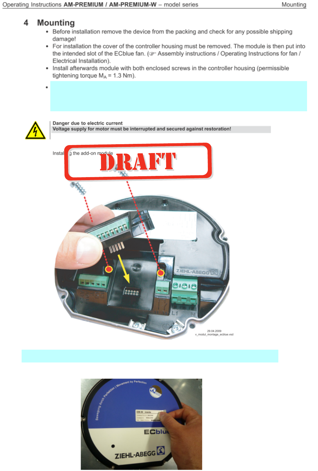
When the AM-PREMIUM-W will be mounted in a fan or an converter of
Ziehl-Abegg AG, the FCC/IC label (EM-W inside) has to be stick on the
housing of the fan or converter.
Sticking the FCC/IC label (EM-W inside) on the
housing of the fan.
Sticking the FCC/IC label (EM-W inside) on the housing of the fan.
When the AM-Premium-W module will be mounted in a fan or converter of
Ziehl-Abegg AG, the FCC/IC label (EM-W inside) has to be stick on the
housing of the converter

5 Electrical installation
5.1 Safety precautions
Danger due to electric current
•Work on electric components may only be carried out by trained electricians or by
persons instructed in electricity under the supervision of an electrician in accordance
with electrical engineering regulations.
•It is forbidden to carry out work on electrically live parts.
5.2 Signal connection or sensor connection to analog inputs (Analog In 2, Analog In 3)
The unit has two analog inputs: Analog In 2
|
E2
|
and Analog In 3
|
E3
|
The connection is independent of the programmed operating mode and from the sensor signal
employed.
•When connecting passive temperature sensorsTF.. (KTY81-210) or PT1000 at terminals “E2 /
T2” and/or “E3 / T3” must be paid attention to no polarity.
For a high interference immunity a capacitor must be connected directly to the sensor (1 nF
parallel). With Ziehl-Abegg temperature sensors type TF.. (KTY81-210) the capacitor is inte-
grated.
•When connecting aktive sensors at the terminals “E2 / GND” and/or “E3 / GND” attention must
be paid to correct polarity, a 24 V DC power supply is integrated.
• For sensors in two-wire-technology (4 - 20 mA signal), the connection is made on the “E1 / 24
V” and/or “E3 / 24 V”, “GND” terminal is omitted.
Attention!
Never apply line voltage to analog inputs!
5.3 Output voltage 0 - 10 V (Analog Out)
The analogoutputs 0 - 10 V can be allocated with various functions (
IO Setup: Analog output “A”).
Connection to terminal “A” - “GND” = “Analog Out” (I
max
10 mA).
It is not permissible to connect outputs of several devices to each other!
5.4 Voltage supply for external devices (+24V, GND)
There is an integrated power supply for external devices, e.g. a sensor. Terminal +24 V, output voltage
tolerance +/- 20%. Max. load current 70 mA.
It is not permissible to connect outputs of several devices to each other!
In case of overload or short circuit (24 V – GND), the external power supply is shut down (multi-fuse).
The device performs a “Reset” and continues operation.
Operating Instructions AM-PREMIUM / AM-PREMIUM-W – model series Electrical installation
L-BAL-E095-GB 1203 Index 004 Part.-No.
7/68
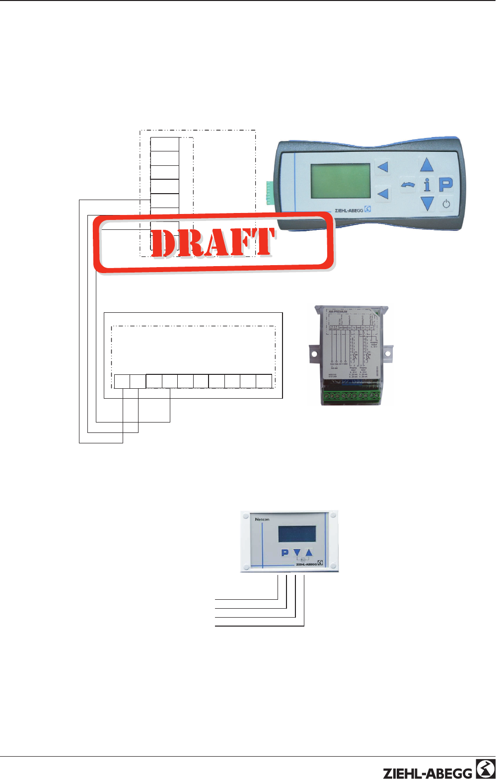
5.5 Connection external terminal type A-G-247NW or AXG-1A(E)
If necessary an external terminal can be connected. This can be e.g. necessary to adapt the pre-
setting during start-up. For information about the current operating condition a terminal can be
permanent attached.
•The connection is made via a 4-strand line at the terminals (D-, D+ and GND).
•e.g., telephone flex e.g. J-Y (St) Y 2x2x0.6 (or similar), maximum line length ca. 250 m.
•Signal “D+” and “D-” (RS 485)
•Type A-G-247NW, Part.-No. 380070, handheld terminal
15.09.2010
v_prem_modul_link_terminal.vsd
AM-PREMIUM
24V GND E2 T2 GND E3 T3 A1
A-G-247NW
+ 3,3 V
IRDA-RXD
IRDA-TXD
IRDA-SD
A
(D+)
B
(D-)
GND
+ 5 V
A
(D+)
B
(D-)
The voltage supply of the terminal is made by the accumulators inserted there or the plug power supply unit.
•Model AXG-1A, Part-No. 349034 for wall mounting
•Model AXG-1AE, Part-No. 349008 for panel mounting
D-
D+
GND
+24 V
13.07.2007
v_terminal_anschluss.vsd
Voltage supply: Terminal “24 V”, “GND”, (I
max
, for terminal approx. 50 mA)
Operating Instructions AM-PREMIUM / AM-PREMIUM-W – model series Electrical installation
L-BAL-E095-GB 1203 Index 004 Part.-No.
8/68
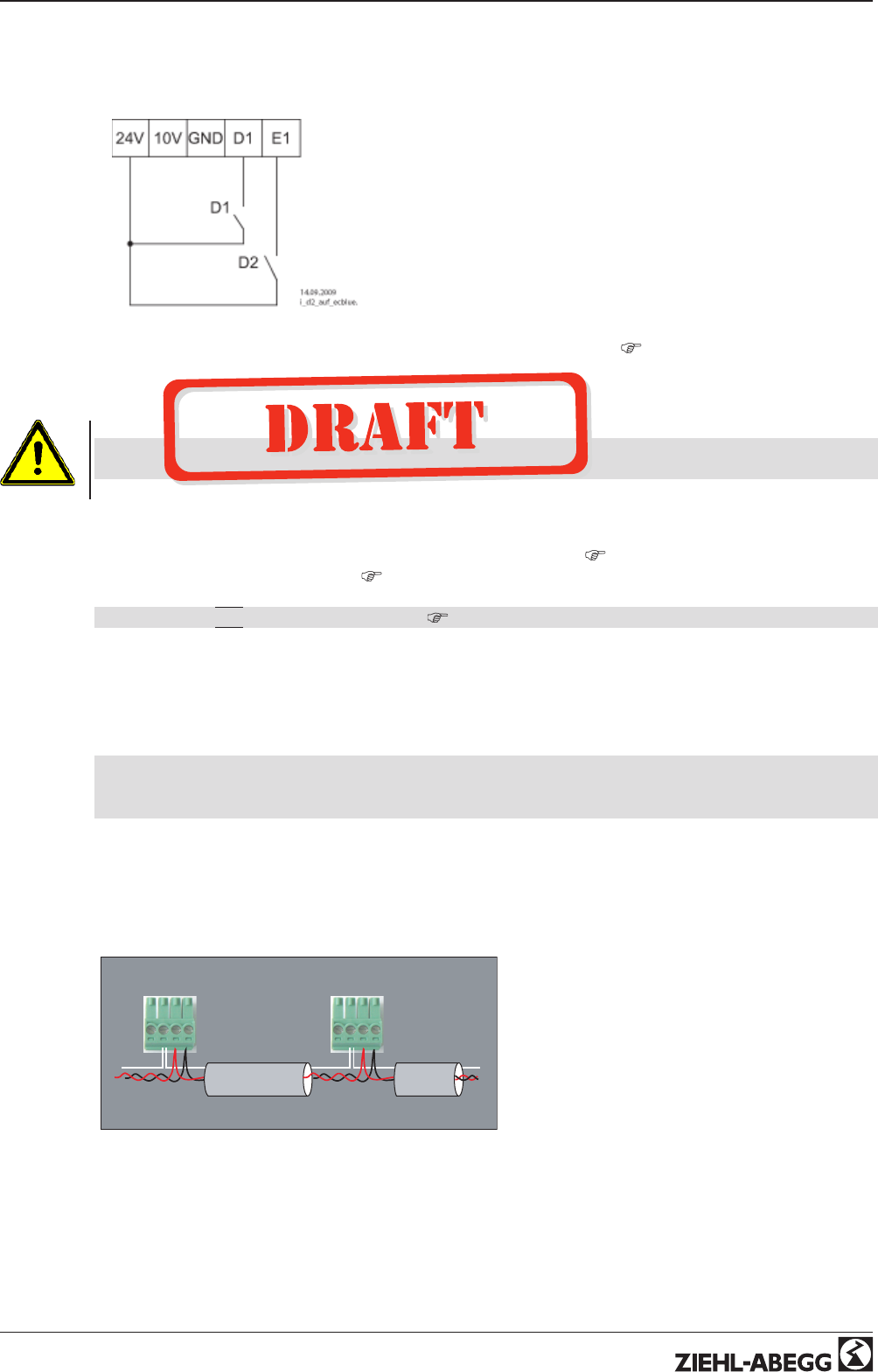
5.6 Digital inputs (D1, E1 = D2)
In the case of use of the module AM-PREMIUM two digital inputs can be programmed. When inserting
the module the analog input “E1” becomes automatically to the second digital input “D2”.
D1: contact at Terminals “D1” - “24 V”
D2: contact at Terminals “E1” - “24 V”
Various functions can be allocated to the digital inputs “D1”and “D2” (
IO Setup: Functions summary
of the digital inputs). Activation via floating contacts (a low voltage of ca. 24 V DC is connected).
Attention!
Never apply line voltage to the digital input!
It is not permissible to connect inputs of several devices to each other!
5.7 Relay output (K1)
The relay output “K1”can have different functions assigned to it (
IO Setup: Function and inversion
of relay output). Max. contact load
ECblue: Technical data and connection diagram.
Connection of the floating contacts of relay “K1” to the terminals 11, 14.
factory setting
|
1K
|
= Operating indication (
IO Setup).
5.8 Communication
5.8.1 Networking via MODBUS-RTU
The device comes equipped with a RS-485 interface for networking via MODBUS. Conntection at: “A
(D+)”, “B (D-)” and “GND”.
A maximum of 64 members can be directly connected to one another, and another 63 members
via a repeater.
The address must be set in the “IO Setup” menu.
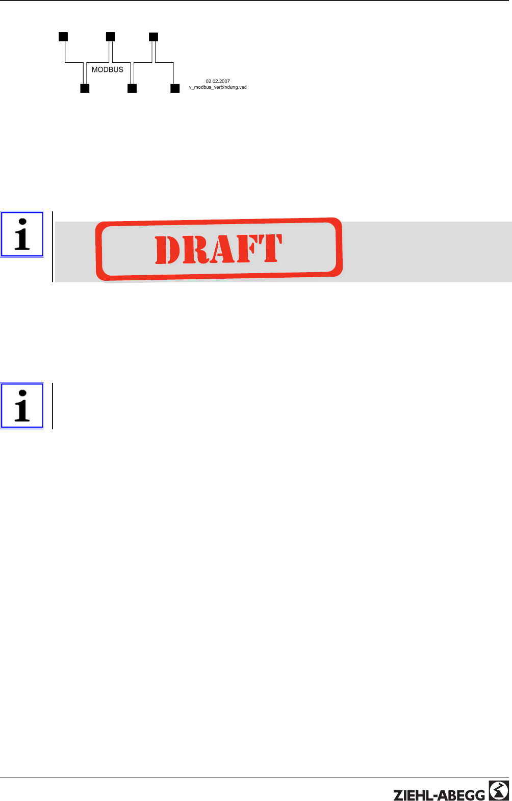
5.8.2 RS-485 - network design and interface parameter
Please ensure the correct connection; i.e. "A (D+)" must always be connected to "A (D+)" of the
next devices. The same applies to "B (D-)" .
In addition, a "GND" connection must be established, as dissimilar potential (over 10 V!) will lead to
the destruction of the RS-485 interface (e.g. lightning).
GND
D+
D-
GND
D+
D-
16.04.200 8
v_m odbus_geraete_ an sch luss.vs d
general example for MODBUS device connection
The data line must be connected from one device to the next. No other type of wiring is allowed!
Always use only two wires of one lead (twisted pair) for the connection.
Operating Instructions AM-PREMIUM / AM-PREMIUM-W – model series Electrical installation
L-BAL-E095-GB 1203 Index 004 Part.-No.
9/68
Examples for MODBUS connection
Recommended wire types
1. CAT5 / CAT7 cables
2. J-Y (St) 2x2x0.6 (telephone wire)
3. AWG22 (2x2 twisted pair)
When using telephone flex with four cable cores, we recommend the following allocation:
“A (D+)” = red, “B (D-)” = black, “GND” = white
Information
•Pay attention to sufficient distance from powerlines and motor wires (min. 20 cm)
•Do not use wire shield
•Except the data link "A (D+)", "B (D-)" and "GND"- connection may no further cable cores
of the data line be used.
•Max. allowed wire length 1000 m (CAT5/7 500 m)
Default interface parameter
Baudrate = 19200
Bits = 8
Patity = Even (None, exception of devices agriculture)
Stop bits = 1
Handshake = none
Information
If any matters are unclear, please contact our V-STE support department for control systems -
ventilation technology. The information sheet "Network structure of MODBUS" R-TIL08_01 contains
detailed information about "MODBUS".
Operating Instructions AM-PREMIUM / AM-PREMIUM-W – model series Electrical installation
L-BAL-E095-GB 1203 Index 004 Part.-No.
10/68

5.8.3 AM-PREMIUM-W Wireless Communication
The type A-G-247NW hand-held terminal can communicate wireless with the type AM-PREMIUM-W
communications module.
In a hard-wired system, wireless communication is primarily designed in order to have a second
interface for communicating with the device (e.g., for configuration and diagnostics).
In the A-G-247NW, for wireless communication with an EC fan type ECblue Basic use the
|
AM-
PREMIUM-W
|
menu item.
Wireless communication is also used by the MODBUS protocol, so it is necessary to assign an
address. Wireless and hard-wired communications use the same address. The address can be
hard-wire assigned via an RS-485.
For pure, wireless communication, it is recommended to assign the address manually.
•Switch on the device you want to re-address and establish a connection with address 247.
•In “IO Setup”, change the address and then switch this device off again.
•Apply the same procedure to the next device.
Radio control key (0 - 9999)
Different from RS-485 communication, wireless communication also has a radio control key (0 -
9999). This radio control key is used to encode the messages and ensures that several networks can
be operated in mutually overlapping radio ranges.
For that reason, every wireless MODBUS network should have its own radio control key if there is
another wireless MODBUS network in the vicinity.
The factory setting is
|
9999
|
.
A radio control key with the value
|
0
|
switches off encoding.
The ECblue must be switched off to save the new radio control key.
The radio control key must be assigned in the same manner as the assignment of the MODBUS
address. The radio control key can be found in the ECblue basic menu in the “IO Setup” menu item.
Technical data for wireless Communication:
Radio communication
standard:
IEEE 802.15.4
Frequency: 2.4 GHz (not licensed wireless band, like WLAN, Bluethooth)
16 wireless channels, default wierless channel 0
Communications range: Short-distance radio, within buildings max. 8 m typically 3 - 5m, free field to 25 m,
generally strongly dependent on interferences
Type of communication: Bi-directional, half dublex
Application protocol: MODBUS-RTU (max. protocol length 125 Bytes and/or 50 register)
Coding: Proprietary through 4-digit number
Network structure: Point - to - point or point - to- mulit point - communication
5.9 Potential at control voltage connections
The control voltage connections (< 50 V) relate to the joint GND potential (Exception: Relay contacts
are potential free). There is a potential separation between the control voltage connections and the
protective earth. It must be ensured that the maximum external voltage at the control voltage
connections cannot exceed 50V (between “GND” terminals and “PE” protective earth). If necessary, a
connection to the protective earth potential can be established, install bridge between “GND” terminal
and the “PE” connection (terminal for screening).
Operating Instructions AM-PREMIUM / AM-PREMIUM-W – model series Electrical installation
L-BAL-E095-GB 1203 Index 004 Part.-No.
11/68

6 Operating by terminal
6.1 Hand held terminal type A-G-247-NW for several members
6.1.1 Display and operating elements of the terminal
Hand held terminal type A-G-247NW
15.09.2010
v_bed_men_a-g-247nw_2nd.vsd
1
2
3
56
4
8
10
ECblue
AXG Mode
USB Filetransfer
A-G-247NW Setup
Mainmenu >>> IXI
9
OFF
7
ON
1 Switch on terminal
2 Program key and open menu
3 Menu selection, increase value
4 Menu selection, reduce value
5 From each menu (member) directly back to the display for “Speed”
6 Escape = exit menu for settings (user), cancel input
7 - Select type of user
- back to selection of user (exit application)
- Switch off terminal (keep key pressed for a few seconds)
8 "Main menu" = momentarily active menu level (
|
>>>
|
= batteries being charged,
|
====-
|
= full)
9 Selection option of the sub-menu (display in menu language English)
10 Key not assigned (soft key, program-dependent function)
Explanation of display (menu User)
04.05.2009
v_display_erkl_A-G-247NW.vsd
11
1
2 3 4 5 6 7 8 9 10
12
13
1. Numeric display 5 digit
2. Moon-Symbol for set point 2
3. Current derating active
4. Alarm-symbol (
list of fault indications)
5. Brake motor or motor heating active
6. Fire-Symbol (heating operation)
7. temperature managment active (power reduction)
8. No connection to Modul (only AM-MODBUS)
9. not used
10. STOP-Symbol (enable)
11. Bargraph Fanlevel
12. Text line 3 figures (display unit, etc.)
13. Text line 16 figures (display text menu.)
Operating Instructions AM-PREMIUM / AM-PREMIUM-W – model series Operating by terminal
L-BAL-E095-GB 1203 Index 004 Part.-No.
12/68
6.1.2 Establish connection to member
1. Open drop-down menu
|
ECblue
|
with the P key.
2. Select type of user with the ▼ + ▲ keys and confirm with the P key.
Setting kind of member
Display Explanation
Main menu IXI P
ECblue
ECblue Apps Setting kind of member
AM-MODBUS
ECblue fan with integrated communication module.
Type AM-MODBUS, Part.-no. 349045
Communication via cable.
AM-MODBUS-W
ECblue fan with integrated communication module.
Type AM-MODBUS-W, Part.-no. 349050
Communication wireless.
AM-PREMIUM
ECblue fan with integrated universal control module.
Type AM-PREMIUM, Part.-no. 349046
Communication via cable.
AM-PREMIUM-W
ECblue fan with integrated universal control module.
Type AM-PREMIUM-W, Part.-no. 349051
Communication wireless.
Confirm address
Netzwerkschlüs-
sel
IXI ◄
9999 For communication wireless:
Set network key an confirm withP-key.
Select device IXI ◄
247
The device address (Device-ID) of the members is factory set to the highest available MODBUS
address: 247
Set address with the ▼ + ▲ keys and confirm this with the P key to establish the first connection.
ZATerminal support ◄
ECblue-247 IXI
☻Successful connection!
ECblue-246 IXI
?
No connection!
Settings are not possible!
In the display the two symbols for alarm and antenna appear (only for AM-MODBUS).
Cause: wrong address, no connection via wire and/or radio (only AM-MODBUS-W).
Operating Instructions AM-PREMIUM / AM-PREMIUM-W – model series Operating by terminal
L-BAL-E095-GB 1203 Index 004 Part.-No.
13/68
6.2 Terminal type AXG-1A(E) for one member
With terminal type AXG-1A(E) connection only to one member possible.
16.09.2009
v_terminal_axg.vsd
explaining display
terminal A-G-247NW
PProgram key and open menu
▼Menu selection, reduce value
▲Menu selection, increase value
▼ + ▲ESC-key combination, Escape = leave menu
6.3 Menu operation
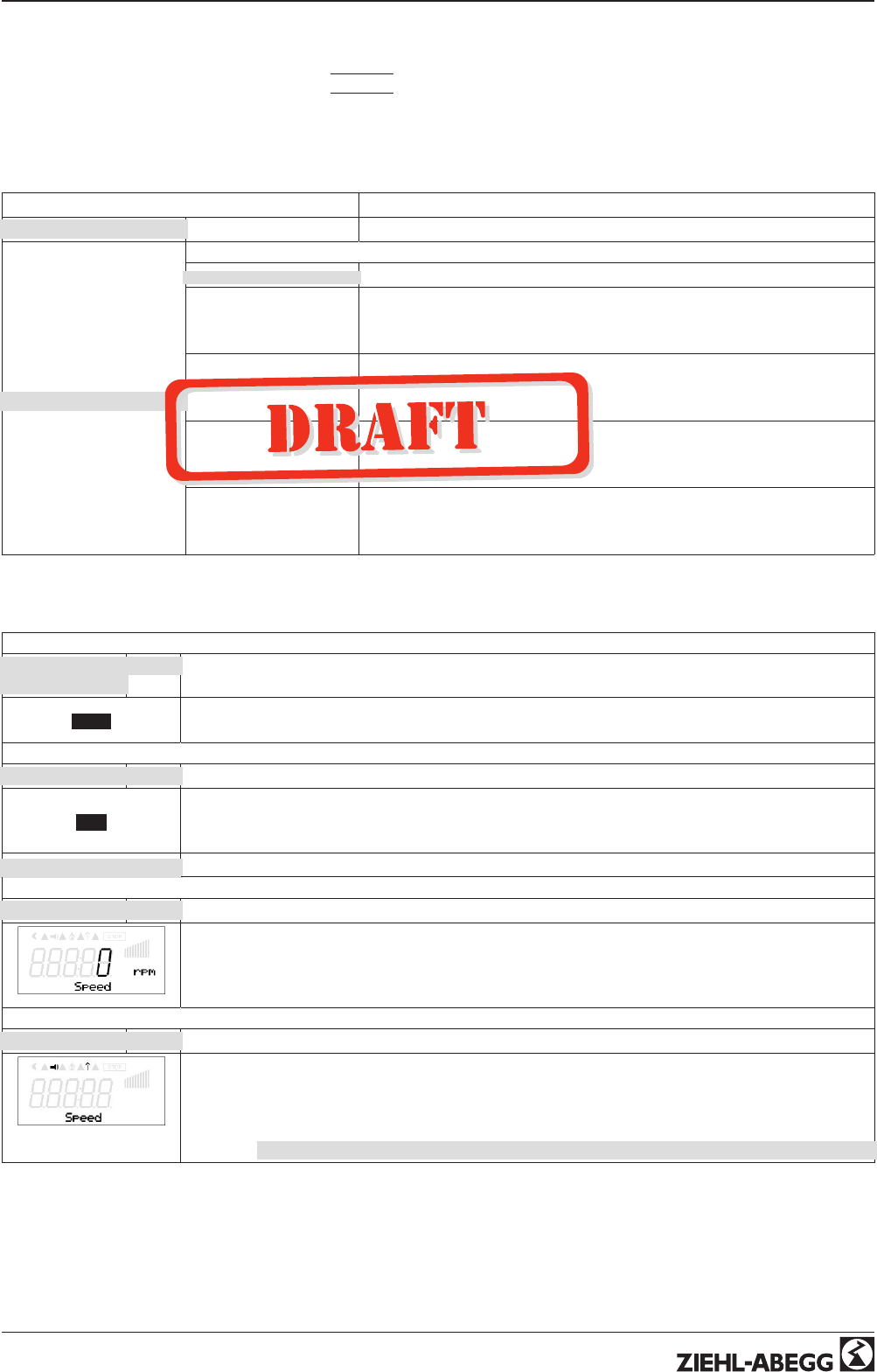
Display after turning on the mains voltage.
description for menu language English = “GB” (delivery status).
Switch over between “Start” and *Actual value with Escape
|
Esc
|
.
Example for mode 1.01 (speed controller).
*actual value depending device type:
- "Speed" / rpm,- "Frequency" / Hz, - "Fanlevel" / %
By pushing the P key one reaches the menu item “START”.P↓ ↑ ESC
▲ ▼One moves up and down within the menu group using the arrow keys.
In the menu point “Language” display language can be selected.
One returns to the menu group “Start” using the ESC (▼ + ▲) shortcut keys.
Operating Instructions AM-PREMIUM / AM-PREMIUM-W – model series Operating by terminal
L-BAL-E095-GB 1203 Index 004 Part.-No.
14/68
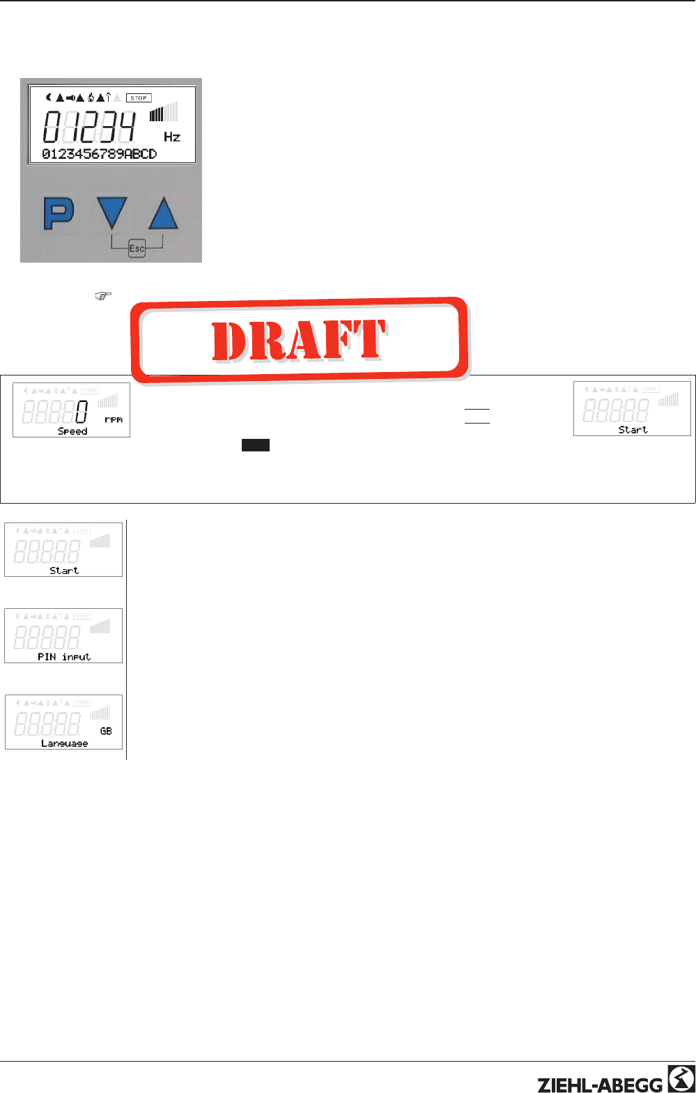
6.4 Menu structure
PIN 0010
STOP
← ← ← ← User Service → → → →
Start
▼
▲Info
▼
▲Setting
▼
▲Events
▼
▲Base setup
P↓ ↑ ESC P↓ ↑ ESC P↓ ↑ ESC P↓ ↑ ESC P↓ ↑ ESC
PIN input Frequency Set Intern1 Motor fault Mode
▲ ▼ ▲ ▼ ▲ ▼ ▲ ▼ ▲ ▼
Language Set external1 Set Intern2 E1 Analog In
Menu dependent on device type
Selection of the menu group (e.g. Base setup) to the right through the ▼-key, to the left through the
▼-key.
You can go to the menu items in the menu groups (e.g. mode of operation) by using the P key. Use
the arrow keys to move up and down within the menu group.
The menu groups consist of one area for the user (user menu) and one area for installation (service).
The service area can be protected against unauthorized access by using a PIN.
In order to simplify the initial start-up operation, the service level is enabled at first (i.e., not protected
by the PIN 0010 (
see Controller Setup, PIN protection = OFF). If PIN protection is activated (ON),
the service menu remains enabled after input of PIN 0010 as long as one is pressing keys. If no keys
are pressed for ca. 15 minutes, the PIN is automatically erased, i.e. the service level is blocked.
To make adjustments, press the P key after selecting the menu item. If the previously set value starts
to ash, it can be adjusted with the ▼ + ▲ keys and then saved with the P key. To exit the menu
without making any changes, use the “Esc” short-key, i.e., the originally set values remain.
Information
After installation of the device has been carried out, PIN protection should be activated (
Controller
Setup)!
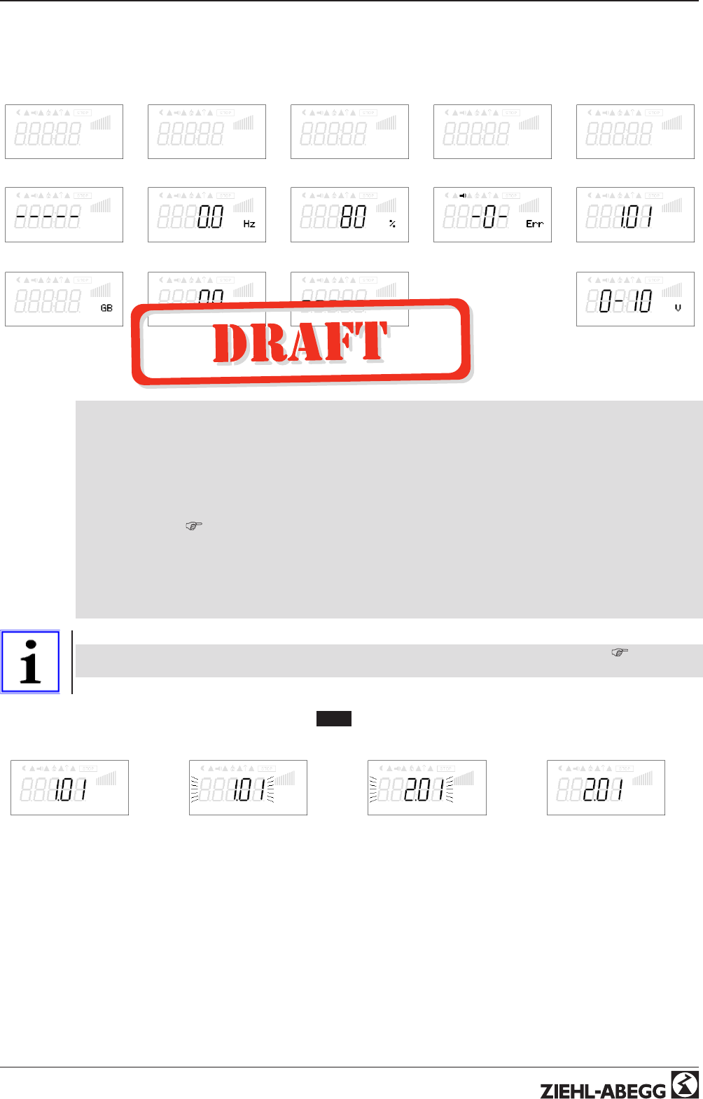
6.5 Example for programming mode 2.01 in “Base setup”
1 2 3 4567
Mode
P
Mode
▲
Mode
P
Mode
Operating Instructions AM-PREMIUM / AM-PREMIUM-W – model series Operating by terminal
L-BAL-E095-GB 1203 Index 004 Part.-No.
15/68
7 Base setup
7.1 Select operation mode
Information
Simple installation is possible through the selection of the preprogrammed mode of operation.
This determines the basic function of the device; factory setting 1.01 = speed controller
(activation via 0 - 10 V signal). The controller configuration is automatically carried out during
selection of the application related mode of operation. The factory presets in accordance with
the mode of operation are based on many years of experience, which is suitable for many
applications. Under special circumstances, these can be individually adapted (
Controller
Setup: “Controller Configuration”).
The purpose of the device is to reach and maintain the target values set. To accomplish this, the
measured actual value (sensor value) is compared with the adjusted target value, and the controlled
value (modulation) is deduced from this.
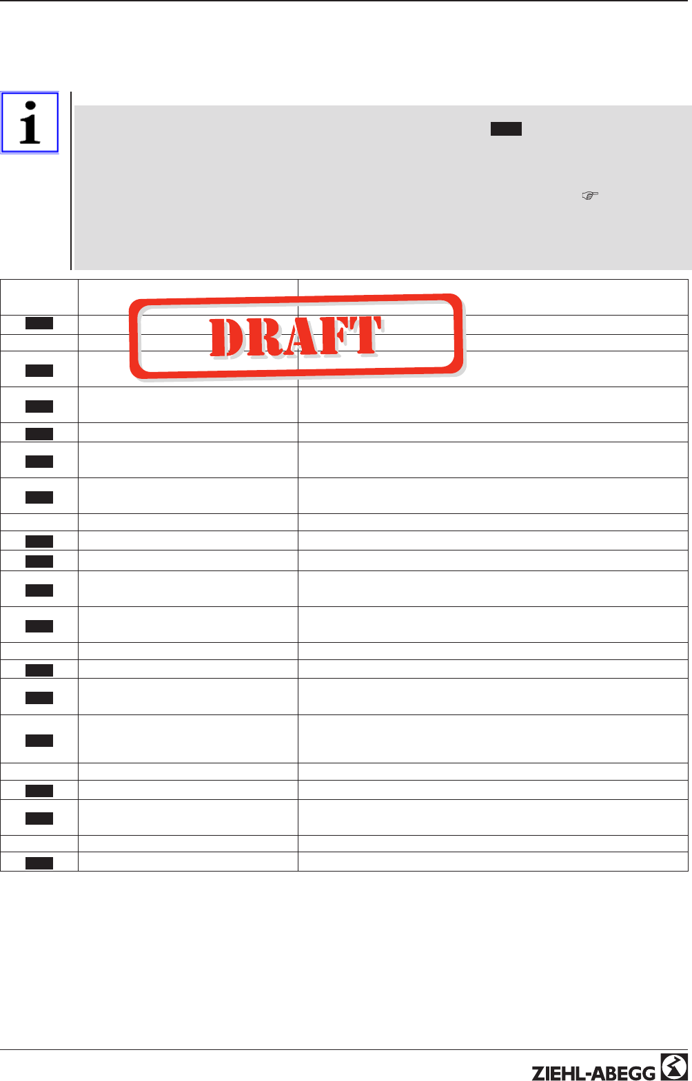
Mode Signal or Sensor
(input) Function
1.01 Signal 0 - 10 V Speed controller, two step operation (factory setting)
2.01 Sensor KTY81-210 / PT1000 (E2) Temperature control airconditioning and refrigeration.
(preset set-point 20.0 °C, P-band 5.0 K)
2.02 Sensor KTY81-210 / PT1000 (E3) Temperature control depending on outdoor temperature
(preset set-point 5.0 °C, - P-band 20.0 K)
2.03 Sensor KTY81-210 / PT1000 (E2) Temperature control with additional functions (shutter and heating)
2.04 1x Sensor KTY81-210 / PT1000 (E2)
1x Sensor KTY81-210 / PT1000 (E3)
Temperature control with two sensors, comparison or average
2.05 1x Sensor KTY81-210 / PT1000 (E2)
1x Sensor KTY81-210 / PT1000 (E3)
Temperature control with two sensors differential temperature
3.01 Sensor MBG.. (E2) Pressure control condensers (refrigeration)
3.02 Sensor MBG..(E2) Pressure control for condensers with input for refrigerant
3.03 1x Sensor MBG..(E2)
1x Sensor MBG..(E3)
Pressure control for two circuit condensers
3.04 1x Sensor MBG..(E2)
1x Sensor MBG..(E3)
Pressure control for two circuit condensers with input for refrigerant
4.01 Sensor DSG.. / MPG.. (E2) Pressure control for ventilation systems
4.02 1x Sensor DSG.. / MPG.. (E2)
1x Sensor KTY81-210 / PT1000 (E3)
Pressure control depending on outdoor temperature
4.03
1x Sensor DSG.. / MPG.. (E2)
1x BUS RS 485
Pressure control depending on outdoor temperature, MODBUS for out-
door temperature and remote control by central operating device type
AXE-200AX
5.01 Sensor DSG.. / MPG.. (E2) Volume control (constant) for ventilation systems
5.02 1x Sensor DSG.. / MPG.. (E2)
1x Sensor KTY81-210 / PT1000 (E3)
Volume control with setpoint depending on outdoor temperature
6.01 Sensor MAL..(E2) Air velocity control e.g. clean room
Operating Instructions AM-PREMIUM / AM-PREMIUM-W – model series Base setup
L-BAL-E095-GB 1203 Index 004 Part.-No.
16/68
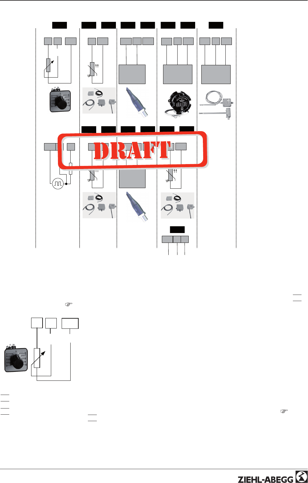
Mode and Signal to E1, E3
16.01.2012
v_e2_e3_signal_sensor_pwm.vsd
A1 E2 GND
0-10 V
10 k
0 - 10 V TF..
24V E2 GND
DSG 0 - 10 V
YE
DSG.. / MPG..
(0 - 10 V)
WHBN
24V E2 GND
MAL 0 - 10 V
3
MAL1/10
(0 - 10 V)
21
31
BN GN
MBG..-I
24V E2
MBG..
(4 - 20 mA)
E2 T2
KTY81-210
PT 1000
GND
1.01 2.01 2.03
.. 3.01 3.02
+6.014.01 5.01
+
2.04 2.05
+
TF..
E3 T3
TF..
KTY81-210
PT 1000
Rext
10 V PWM
f = 1...10 kHz @ Rext = 1 k2
f = 1 kHz @ Rext = 10 k2
t = 0...100 %
GND E2 A1
31
BN GN
MBG..-I
24V E3
MBG..
(4 - 20 mA)
GND
3.03 3.04
+4.02 5.02
+
TF..
E3 T3
TF..
KTY81-210
PT 1000
4.03
D+GND D-
Data
RS-485
7.2 External Setpoint / External speed setting in manual operation
External setpoint setting or external manual operation are possible using a 0 - 10 V (0 - 20 mA, 4 - 20 mA) signal at the “E3” and
“GND” terminals. Configure “E3” in Base setup. For potentiometers, program Analog Out 1 (terminal “A1”) to the function
|
1A
|
=
“+10 V” (as factory setting
IO Setup).
E3 Analog In = factory setting 0 - 10 V
A1 E3 GND
Signal 0-10 V
10 k
16.01.2012
v_extern_poti_e3.vsd
External Setpoint via external signal instead of “Setpoint 1”. The “external Setpoint” function must be activated in base setup
|
1E
|
for “E3 function”. The active external Setpoint value is displayed in the “info” menu group.
External speed setting in manual operation. The “external manual operation” function must be activated in the basic settings
|
2E
|
for “E3 function”. Switchover between settings on the device and external manual operation via the digital input (
IO
Setup: “Control / manual operation”
|
7D
|
).
Operating Instructions AM-PREMIUM / AM-PREMIUM-W – model series Base setup
L-BAL-E095-GB 1203 Index 004 Part.-No.
17/68
8 Start-up
8.1 Prerequisites for commissioning
Attention!
1. You must mount and connect the device in accordance with the operating instructions.
2. Double check that all connections are correct.
3. Make sure that no persons or objects are in the fan's hazardous area.
8.2 Procedure for commissioning
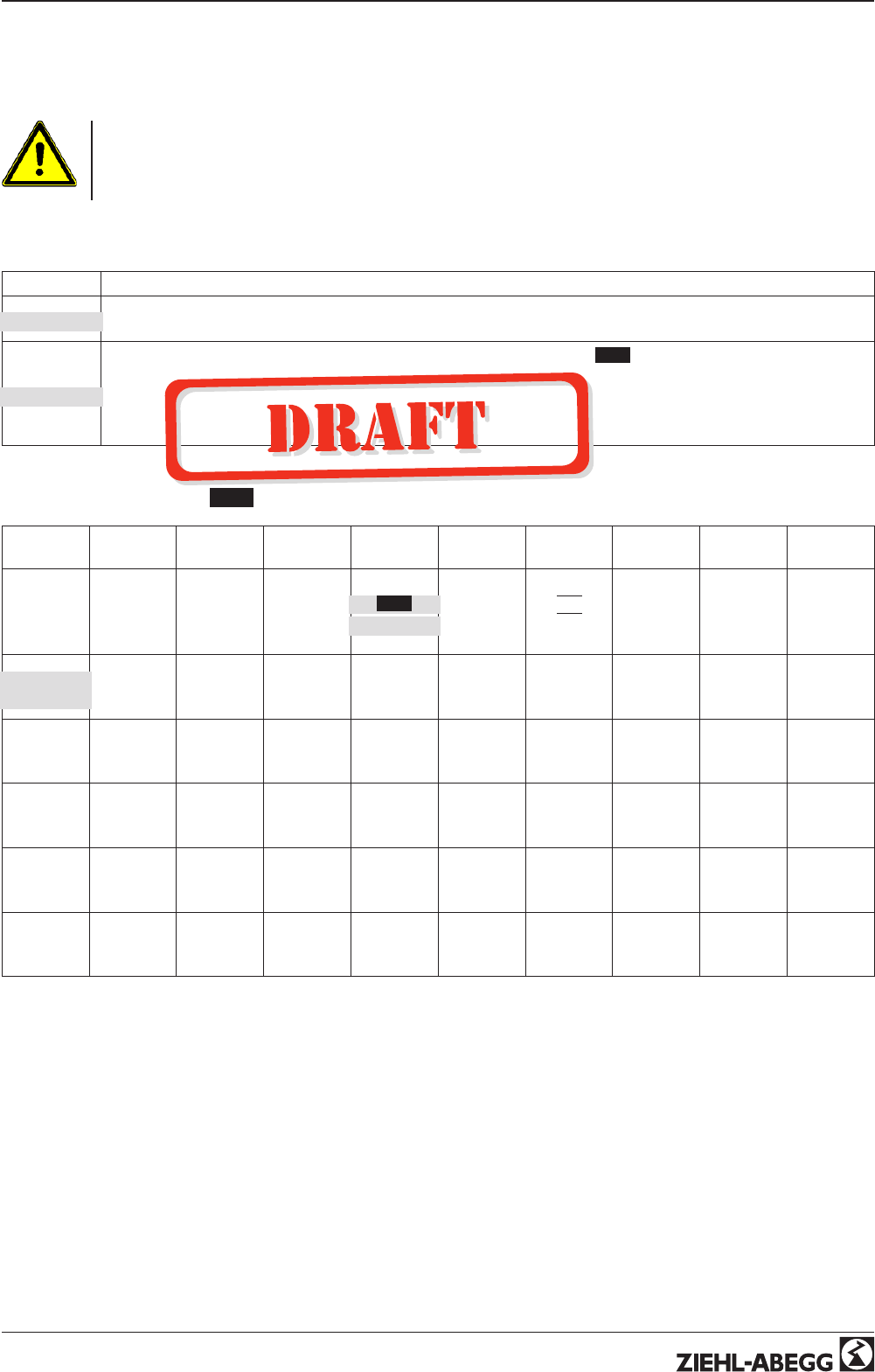
Sequence Setting
1If necessary, set the menu language in Menu group “Start”.
(Factory setting Englisch: “Language GB”)
2
Set the operating mode in the Base setup menu group (factory settings 1.01 = speed controllers).
Attention!
When saving the operating mode, the respective preset factory operating-mode setting is loaded. That means,
the settings you have made, e.g., in “Motor Setup” are lost. An exception: the menu language setting remains
preserved.
8.3 Menu Mode 1.01
Start Info Setting Events Base
setup
Controller
Setup IO Setup Limits Motor
Setup Diagnostic
- - - -
PIN input
0 rpm
Speed
200 rpm
Set Intern1
-0-
Factory
sett.
1.01
Mode
OFF
PIN Protec-
tion
|
1A
|
A Function
OFF
Level.
Function
20 sec
Rampup
time
OTC
00012:56:-
15
GB Lan-
guage
0.0 A
Motor cur-
rent
- - - - -
Set Intern2
-1-
Sensor 1
0 - 10 V
E2 Analog
In
OFF
Set protec-
tion
0.0 V
A min.
- - - - -
Level min
20 sec
Rampdown
time
OTM
00010:56:-
11
OFF
Reset
0 rpm
Set exter-
nal1
0 rpm
Min. Speed
-3-
ext. Fault
OFF
E3 Func-
tion
OFF
Save User
Setup
10.0 V
A max.
- - - - -
Level max.
OFF
Suppres-
sion1
585 V
DC-Voltage
1.01
Mode
1800 rpm
Max.
Speed
- - - - -
E3 Analog
In
- - - - -
Limit
OFF
A Inverting
- - - - -
Level Delay
- - - - -
Range1
min.
244 V
Line volt-
age
4.00
ECblue
Premium
ON
Set exter-
nal1
- - - - -
Group 2
ON value
OFF
D1 Func-
tion
OFF
Lmt E2
Function
- - - - -
Range1
max.
29.5 °C
Heatsink
1.01
Basic Ver-
sion
- - - - -
nmin at
Group2
- - - - - -
D1 Invert-
ing
- - - - -
Lmt E2 min
OFF
Suppres-
sion1
29.5 °C
Capacitor
Operating Instructions AM-PREMIUM / AM-PREMIUM-W – model series Start-up
L-BAL-E095-GB 1203 Index 004 Part.-No.
18/68
9 Programming
9.1 Speed controller 1.01
9.1.1 Base setup 1.01
Base setup
Base setup
Mode
Mode
Factory setting Mode: 1.01
E2 Analog In
E2 Analog In
Selection: 0 - 20 mA, 4 - 20 mA, Bus (Inverting
IO Setup)
Factory setting: 0 - 10 V
E3 Function
E3 Function (only for special applications)
Analog input 2 “E3 function”factory set at “OFF”.
For operation with a second signal and switch over via floating contact set function for
“E3” to
|
1E
|
(
IO Setup: function
|
4D
|
).
For operation with a second signal and automatic control at the higher level. Set “E3”
Function to
|
4E
|
.
E3 Analog In
E3 Analog In
As long as no allocation has been carried out display:
|
- - - - -
|
Selection: 0 - 20 mA, 4 - 20 mA, Bus (Inverting
IO Setup)
Factory setting: 0 - 10 V
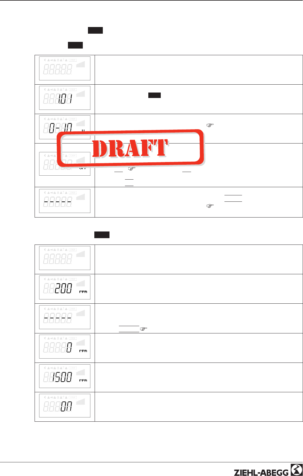
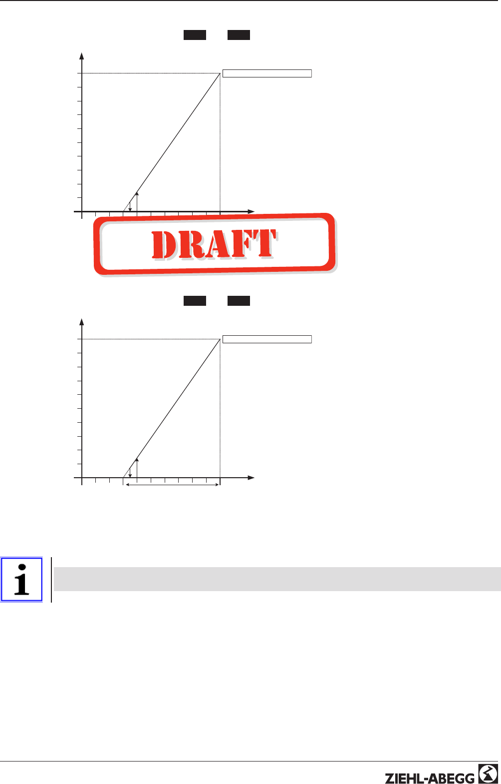
9.1.2 Setting for operation 1.01
Setting
Setting
Set Intern1
Set Intern1
Setting range manual speed setting: 0 rpm... “Max. Speed”
Factory setting: 200 rpm
Set Intern2
Set Intern2
Setting “Set Intern 2” e.g. reduced value for night operation.
Switch over intern 1/2 by external contact (as long as no allocation is carried out:
Display:
|
- - - - -
|
IO Setup).
Min. Speed
Min. Speed
Setting range: 0 rpm... “Max. Speed”
Factory setting: 0 rpm
Max. Speed
Max. Speed
Setting range: Rated speed...0 rpm (takes priority over setting “Min. Speed”)
Factory setting: Rated speed
Set external1
Set external1
“ON” (factory setting) = speed setting by external Signal
“OFF” = Setting “Set Intern1”
Operating Instructions AM-PREMIUM / AM-PREMIUM-W – model series Programming
L-BAL-E095-GB 1203 Index 004 Part.-No.
19/68
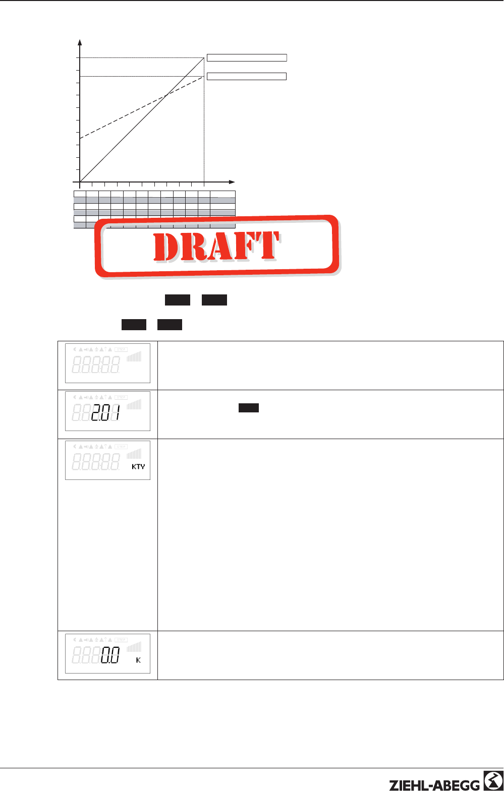
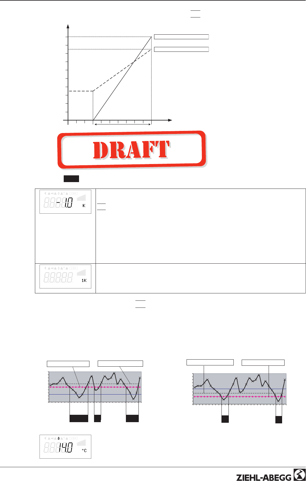
Diagram setting signal and output voltage (Idealized principle diagram)
nM
50 %
100 %
0 1 2 3 4 5 6 7 8 9 10
10 9 8 7 6 5 4 3 2 1 0
0 2 4 6 8 10 12 14 16 18 20
20 18 16 14 12 10 8 6 4 2 0
4 5,6 7,2 8,8 10,4 12 13,6 15,2 16,8 18,4 20
20 18,4 16,8 15,2 13,6 12 10,4 8,8 7,2 5,6 4
0 – 10 V
10 – 0 V
0 – 20 mA
20 – 0 mA
4 – 20 mA
20 – 4 mA
Min.
Min. 0 % Max. = 100 %
Min. 35 % Max. = 85 %
09.05.2007
v_nmotor_101.vsd
Si
100 % = Rated speed
nM Motor speed
Si Signal
9.2 Temperature control 2.01 ... 2.05
9.2.1 Basic setting 2.01 ... 2.05
Base setup
Base setup
Mode
Mode
Mode selection e.g. 2.01
E2 Analog In
E2 Analog In
In all group 2 operating modes (2.01, 2.02, 2.03, ....)
“E2 Analog In” factory set to “KTY” (sensors type TF..) at terminals “E2” and “T2”
(measuring range: -50.0...+140 °C).
Alternative selection sensor
•PT1000 to Terminals “E2” and “T2” (Measuring range -50.0...+140 °C)
•MTG-120V active sensor with 0 - 10 V output at terminals “E2” and “GND”
(measuring range: -10...+120 °C)
Alternative selection signal at terminals “E2” and “GND”: 0 - 10 V, 0 - 20 mA, 4 - 20 mA.
The sensor measurement range must be entered in order to display the actual value
correctly.
Example with a 0 - 10 V sensor and 0 - 100 °C measurement range:
E2 Analog In = 0 - 10 V, E2 Min. = 0.0 °C, E2 Max. = 100.0 °C, E2 Decimally = 1, E2
Unit = °C
E2 Offset
E2 Offset
Sensor calibration with calibrated comparison device
Operating Instructions AM-PREMIUM / AM-PREMIUM-W – model series Programming
L-BAL-E095-GB 1203 Index 004 Part.-No.
20/68
E3 Function
E3 Function (only for special applications)
•Function
|
1E
|
= External Setpoint e.g. via external signal (0 - 10 V) instead of
“Setpoint1”
–For sensor type “E2 Analog In” = “KTY or PT1000”: 0 - 10 V
-50.0...+140
°C.
–For sensors with active signal: 0 - 10 V
0 - 100 % sensor measuring range.
•Function
|
2E
|
= External manual operation via external signal (0 - 10 V). Switch
over between settings on the device and external manual operation via digital
input (
IO Setup: function
|
7D
|
).
•Function
|
7E
|
Measurement value = Measurement value e.g. for limit indication,
display in Info menu “E3 Actual”.
Modes with two sensors
The function is automatically jointly programmed in operating modes using 2 sensors.
The second analog input is thus allocated and additional function allocations are not
possible.
•2.04 E3 Function at
|
4E
|
preprogrammed = comparison value with control to
higher temperature. Alternative: average of 2 measuring points for this must be
reprogrammed on function
|
3E
|
preprogrammed sensor type “KTY”.
•2.05 E3 Function at
|
5E
|
preprogrammed = regulation on difference temper-
ature between sensor 1 and sensor 2. Preprogrammed sensor type “KTY”.
E3 Analog In
9.2.2 Settings for operation modes 2.01 ... 2.05
2.01 Temperature control simple
2.02 Temperature control depending on outdoor temperature (Special function: Sensor connection at “E3”,
display and setting under “E2”).
2.03 Temperature control with pre-programmed additional functions (heating, shutter, temperature monitoring).
2.04 Temperature control with 2 sensors
Comparison with control to higher value “E3 Function” set to comparison
|
4E
|
. Display during operation:
“Control value ”
Alternative: Average calculation of 2 measuring places “E3 Function” set to
|
3E
|
. Display during oper-
ation: “Average E2 / E3 ”
2.05 Temperature control with 2 sensors, regulation on difference temperature.
Display during operation: “Value of E2 - E3” in K, “E2” = reference temperatur, “E3” causes positiv (E3 <
E2) or negative (E3 >E2) difference.
Setting
Setting
Setpoint1
Setpoint1
Setting range: with passive sensor type “KTY”, “PT1000” : -50.0...150.0 °C
Factory setting: 2.01 , 2.03 , 2.04 : 20.0 °C
at 2.02 : 5.0 °C
at 2.05 : 0.0 °C
Setting range: at active sensor type “MTG-120V”: -10.0...+120.0 °C
Factory setting: 2.01 - 2.05 : 55.0 °C
Setpoint2
Setpoint2
Setting “Setpoint 2” e.g. reduced value for night operation.
Switch over Setpoint 1/2 by external contact (as long as no allocation is carried out:
Display:
|
- - - - -
|
IOSetup).
Operating Instructions AM-PREMIUM / AM-PREMIUM-W – model series Programming
L-BAL-E095-GB 1203 Index 004 Part.-No.
21/68
Pband
Pband
Narrow control range = Short control times
Wide control range = Longer control times and more stable control
Passive sensor type “KTY”, “PT1000”
Setting range: 0 - 200.0 K (Kelvin)
Factory setting: 5.0 K, (at 2.02 : 20.0 K)
active Sensor type “MTG-120V”
Setting range: 0.0...+130.0 K
Factory setting: 65.0 K
Min. Speed
Min. Speed
Setting range: 0 rpm... “Max. Speed”
Factory setting: 0 rpm
Max. Speed
Max. Speed
Setting range: Rated speed...0 rpm (takes priority over setting “Min. Speed”)
Factory setting: Rated speed
Manual mode
Manual mode
“OFF” = automatic control as function of the set parameters (Factory setting)
“ON” = automatic control without function, speed setting in menu “Speed manual”
Speed man.
Speed Manual mode
Manual speed setting without influence by the external signal.
Activation by menu “Manual mode” or external contact at digital input (
IO Setup).
Setting range: 0 rpm...Rated speed, Factory setting: 200 rpm
For information about deactivated regulation the adjusted value for manual speed is
indicated alternating with the actual value.
9.2.3 Functional diagrams temperature control
Example 1: Temperature control in factory setting “Cooling function” (Idealized principle diagram)
nM
50 %
100 %
I
Min.
Min. 0 % Max. = 100 %
Min. 35 % Max. = 85 %
20 °C
S
10 K
R
30 °C 09.05.2007
v_tempcontrol_cool_nmotor.vsd
(Controller Setup: “Val > Set = n+” to “ON”)
nM Motor speed
S Setpoint
R Pband
I Actual value
Operating Instructions AM-PREMIUM / AM-PREMIUM-W – model series Programming
L-BAL-E095-GB 1203 Index 004 Part.-No.
22/68
Example 2: Temperature control in “Heating function” (Idealized principle diagram)
nM
50 %
100 %
I
Min.
Min. 0 % Max. = 100 %
Min. 35 % Max. = 85 %
20 °C
S
10 K
R
10 °C
Max.
09.05.2007
v_tempcontrol_heat_nmotor.vsd
(Controller Setup: “Val > Set = n+” to “OFF”)
nM Motor speed
S Setpoint
R Pband
I Actual value
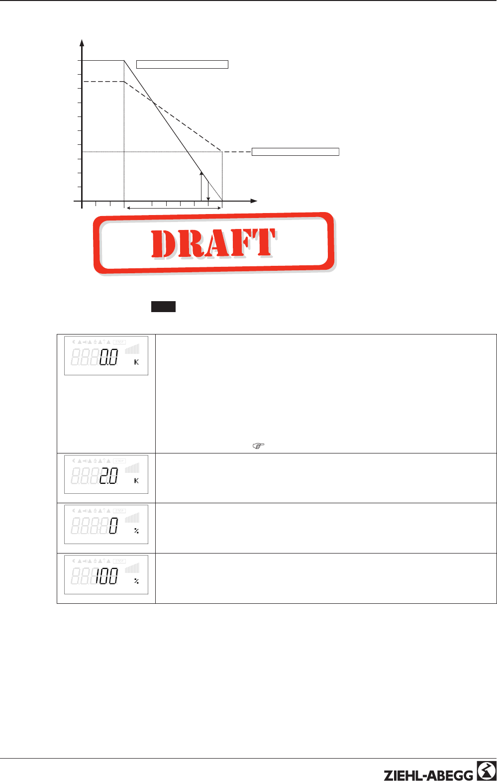
9.2.4 Additional for mode 2.03 : Signal output 0 - 10 V
The 0 - 10 V output signal can, e.g., be used for triggering a shutter or heating.
Offset AnalogOut
Offset AnalogOut
The target value for this output is the target value (Setpoint) for the ventilation “offset”
setting.
Adjustment: range +/- 10 K relative to the active Setpoint.
Example for triggering a shutter servomotor:
At factory setting “0 K” = synchronous operation.
The analog output is factory set to increasing activation during increasing temperature.
Reprogramming to “Heating function”, i.e., increasing modulation during decreasing
temperature is possible (
IO Setup).
Pband AnalogOut
Pband AnalogOut
Pband AnalogOut = separately adjustable range of control (P-band) for 0 - 10 V output
Setting range: 0...102.0 K
Factory setting: 2.0 K
Min. AnalogOut
Min. AnalogOut
Min. AnalogOut = Minimal output voltage
Setting range: 0...100 % = 0 - 10 V
Factory setting: 0 %
Max. AnalogOut
Max. AnalogOut
Max. AnalogOut = Maximal output voltage,
Setting range: 100...0 % = 10 - 0 V
Factory setting: 0.0 K
Operating Instructions AM-PREMIUM / AM-PREMIUM-W – model series Programming
L-BAL-E095-GB 1203 Index 004 Part.-No.
23/68
Example for signal out 0 - 10 V (IO Setup: “A function” =
|
6A
|
)
Max. Analog Out
10 V
50 %
100 %
I
Min. Analog Out
Min. 0 % Max. = 100 %
Min. 35 % Max. = 85 %
20 °C
S
10 K
R
30 °C 09.05.2007
v_signal_ausgang_0_10_v.vsd
Example: Setpoint ventilation 25.0°C, Offset -5.0 K, Pband 10.0 K
S Setpoint Ventilation +/- Offset
R Pband
I Actual value
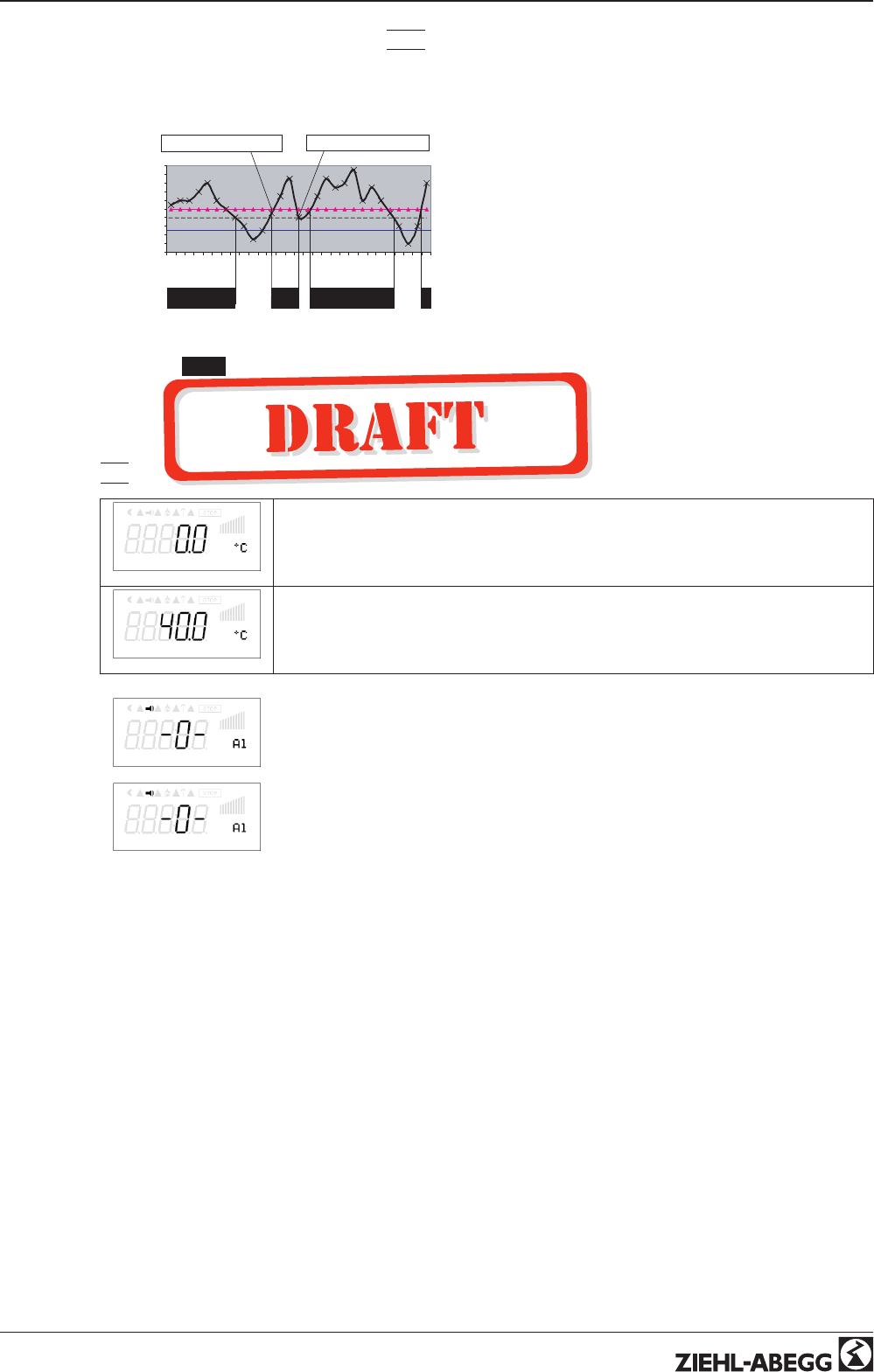
9.2.5 For mode 2.03 : Relay output for Heating or Cooling
OffsetDigitalOut
OffsetDigitalOut
Offset Digital Out = Offset for relay output (“K1” has to be reprogrammed to function
|
9K
|
).
The relay operating point deviates by the adjusted offset of the Setpoint of the ventila-
tion.
Setting range: -10.0...+10.0 K
Factory setting: -1.0 K
•“0.0 K” set, i.e. heating “ON” when: actual value = Setpoint
•During negative offset value heating “ON” when: actual value = Setpoint - offset
•During positive offset value heating “ON” when: actual value = Setpoint + offset
Hyst.DigitalOut
Hyst.DigitalOut
Switching hysteresis of the relay
Setting range: 0...10 K, Factory setting: 1.0 K (Kelvin)
Temperature variation with setting
|
9K
|
for K1 function in IO Setup e. g. for controlling a
Heating.
If the ambient temperature is lower than the set operating point, the heating remains switched on. If
the ambient temperature exceeds the set operating point of the heating by 2 K (Kelvin), the heating is
switched off. I.e., the release point is situated at the hysteresis value over the operating point.
Example:
Setpoint 15.0 °C, Offset +5.0 K, Hysteresis 2.0 K
Example:
Setpoint 20.0 °C, Offset -5.0 K, Hysteresis 2.0 K
10
12
14
16
18
20
22
24
26
28
30
1 3 5 7 9 11 13 15 17 19 21 23 25 27 29
[min]
[°C]
ON ON ON
ON = 15°C + 5 K = 20 °C OFF = 20°C + 2 K = 22 °C
16.03.2007
v_relais_heizen_9k_pos_offset.vsd
10
12
14
16
18
20
22
24
26
28
30
1 3 5 7 9 11 13 15 17 19 21 23 25 27 29
[min]
[°C]
ON
OFF = 15°C + 2 K = 17 °C ON = 20°C - 5K = 15 °C
ON
16.03.2007
v_relais_heizen_9k_neg_offset.vsd
E2 Actual
The activated heating is indicated over the fire symbol in the display.
Operating Instructions AM-PREMIUM / AM-PREMIUM-W – model series Programming
L-BAL-E095-GB 1203 Index 004 Part.-No.
24/68
Temperature variation with setting
|
10K
|
for “K1” function in IO Setup e. g. for activation of the
cooling.
Example:
Setpoint 15.0 °C, Offset +5.0 K, Hysteresis 2.0 K
10
12
14
16
18
20
22
24
26
28
30
1 3 5 7 9 11 13 15 17 19 21 23 25 27 29
[min]
[°C]
ON ON ON
ON = 15°C + 5 K = 20 °C OFF = 20°C - 2 K = 18 °C
16.03.2007
v_relais_kuehlen_10k_pos_offset.vsd
If the ambient temperature is higher than the set operat-
ing point, the cooling remains switched on. If the ambient
temperature falls below the set operating point of the
cooling by 2 K (Kelvin), it is switched off. I.e., the OFF
point is situated at the hysteresis value under the ON
point.
9.2.6 For mode 2.03 Relay output for temperature monitoring
If the set value for the “minimum alarm” is not reached or the set value for the “maximum alarm” is
exceeded, a message is generated via the alarm symbol in the display. In addition, „Lmt E1 min“ is
displayed alternately with the actual value for the minimum alarm and Lmt E1 max for the „Maximum
alarm“. An external message follows via the factory-assigned “K1” relay. (IO Setup: K1 function =
|
2K
|
).
Alarm Minimum
Alarm Minimum
Setting range: OFF / -26.9...75.0 °C
Factory setting: 0.0 °C
Alarm Maximum
Alarm Maximum
Setting range: OFF / -26.9...75.0 °C
Factory setting: 40.0 °C
Lmt E2 min.
Example for display if falling below setting “Alarm Minimum” alternating to the actual
value display.
Relay “K1” disengages (if not inverted).
Lmt E2 max.
Example for display if exceeding setting “Alarm Maximum” alternating to the actual
value display
Relay “K1” disengages (if not inverted).
Operating Instructions AM-PREMIUM / AM-PREMIUM-W – model series Programming
L-BAL-E095-GB 1203 Index 004 Part.-No.
25/68
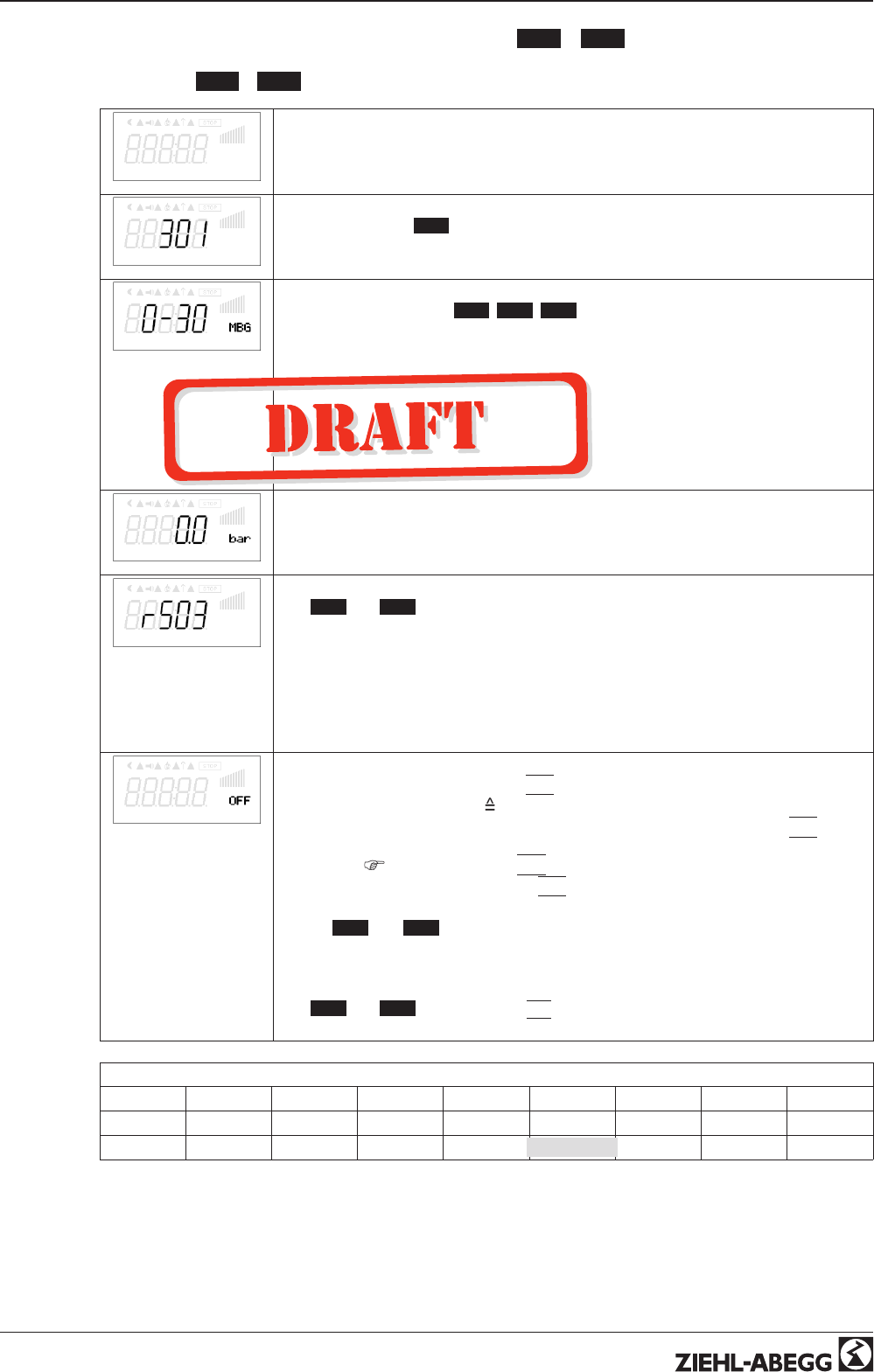
9.3 Pressure control for condensers refrigeration 3.01 ... 3.04
9.3.1 Base setup 3.01 ... 3.04
Base setup
Base setup
Mode
Mode
Mode selection e.g. 3.01
E2 Analog In
E2 Analog In
For all Modes in Group 3 ( 3.01 , 3.02 , 3.03 , ...)
“E2 Analog In” factory setting to “MBG-30I”.
(measuring range 0..30 bar) proportional output 4 - 20 mA
Selection sensor: MBG-30I, MBG-50I, DSF2-25
Alternative selection signal: 0 - 10 V, 4 - 20 mA. The sensor measurement range must
be entered in order to display the actual value correctly.
Example 0 - 10 V sensor and measuring range 0 - 20 bar:
E2 Analog In = 0 - 10 V, E2 Min. = 0.0 bar, E2 Max. = 20.0 bar, E2 Decimals = 1, E2
Unit = bar
E2 Offset
E2 Offset
Sensor calibration with calibrated comparison device
E2 Refrigerant
E2 Refrigerant
With 3.02 and 3.04 operating modes with input of the refrigerant, the device automati-
cally calculates the corresponding temperature for the measured pressure. The set-
tings for offset, target value and the controlling range are then carried out in °C or K.
Calculation for relative pressure (differential measurement of pressure relative to am-
bient pressure). No further settings are necessary for pressure sensors model e.g.
“MBG-30I” or “MBG-50I” (measurement range 0 - 30 bar or 0 - 50 bar). In the case of
sensors with other measurement ranges, the “E2 Min. value” and the “E2 Max. Value”.
Setting in “bar” although unit display is in “°C”!
E3 Function
E3 Function (only for special applications)
•External setpoint = Function
|
1E
|
by external signal (0 - 10 V) instead of
“Setpoint 1”. 0 - 10 V
0 - 100 % sensor measuring range.
•External manual operation via external signal (0 - 10 V) = Function
|
2E
|
Switch
over between settings on the device and external manual operation via digital
input (
IO Setup: fuction
|
7D
|
).
•Measurement value = function
|
7E
|
e.g. for limit indication, display in Info menu
“E3 Actual”.
Modes 3.03 and 3.04 with two sensors
The function is automatically jointly programmed in operating modes using 2 sensors.
The second analog input is thus allocated and additional function allocations are not
possible.
With 3.03 and 3.04 E3 Function at
|
4E
|
preprogrammed = comparison value with
control to higher value (two circuit condensers).
Selection of the refrigerants:
R12 R13 R13b1 R22 R23 R32 R114 R134a R142B
R227 R401 R401A R401B R402 R402A R402B R404A R407A
R407B R407C R410A R500 R502 R503 R507 R717
Operating Instructions AM-PREMIUM / AM-PREMIUM-W – model series Programming
L-BAL-E095-GB 1203 Index 004 Part.-No.
26/68
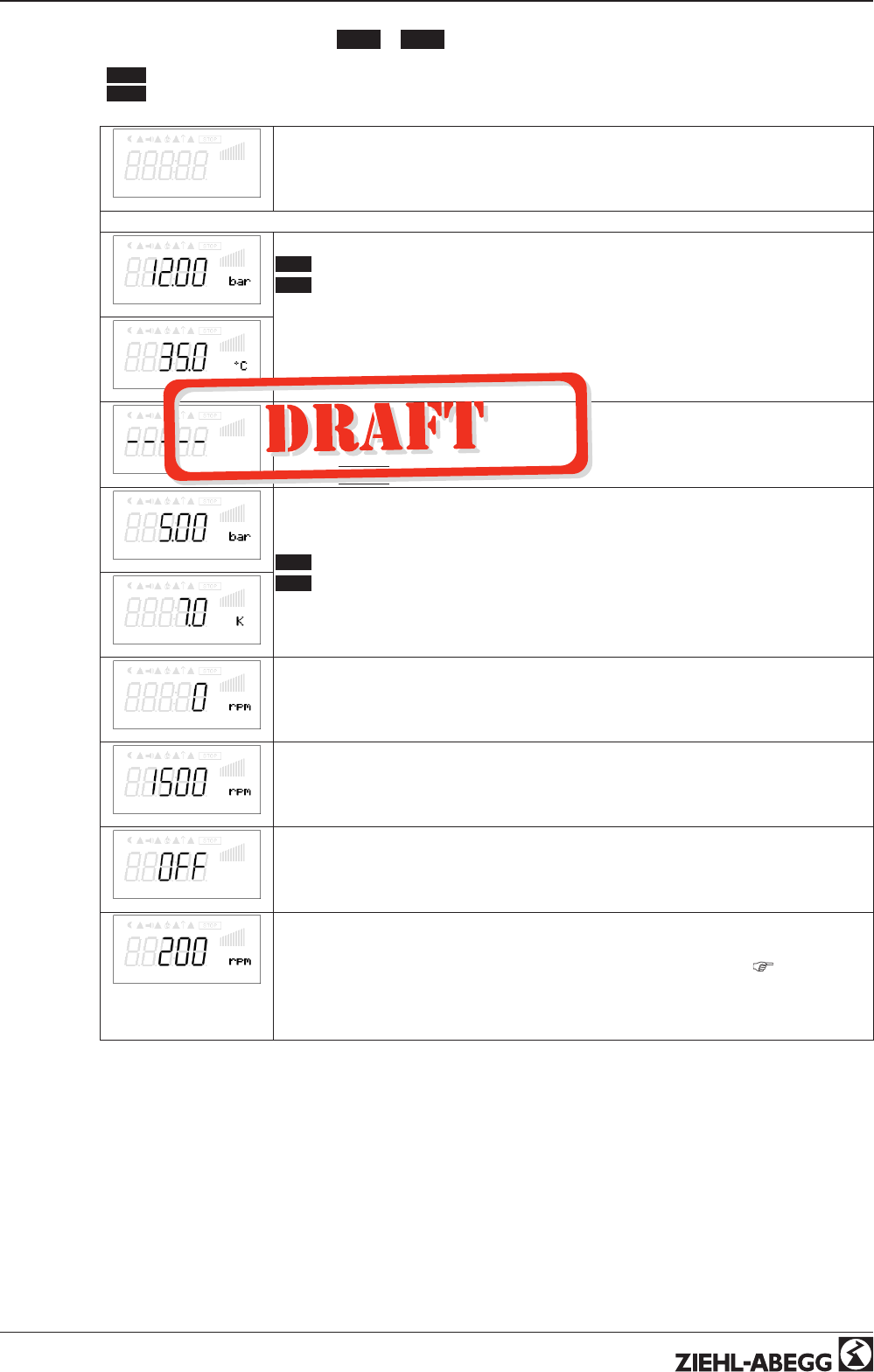
9.3.2 Setting for operation modes 3.01 ... 3.02
3.01 Pressure control condensers, setting Setpoint in bar
3.02 Pressure control for condensers with input for refrigerant, Setpoint in °C
Setting
Setting
Setpoint1
Setpoint1
3.01 Setting range: in measuring range of sensor, factory setting: 12.0 bar
3.02 Setting range: dependent on the selected refrigerant, factory setting: 35.0 °C
Setpoint1
Setpoint2
Setpoint2
Setting “Setpoint 2” e.g. reduced value for night operation.
Switch over Setpoint 1/2 by external contact (as long as no allocation is carried out:
Display:
|
- - - - -
|
IOSetup).
Pband
Pband
Narrow control range = Short control times
Wide control range = Longer control times and more stable control
3.01 Setting range: in measuring range of sensor, factory setting: 5.0 bar
3.02 Setting range: dependent on the selected refrigerant and in measuring range of
sensor, factory setting 7.0 K
Pband
Min. Speed
Min. Speed
Setting range: 0 rpm... “Max. Speed”
Factory setting: 0 rpm
Max. Speed
Max. Speed
Setting range: Rated speed...0 rpm (takes priority over setting “Min. Speed”)
Factory setting: Rated speed
Manual mode
Manual mode
“OFF” = automatic control as function of the set parameters (Factory setting)
“ON” = automatic control without function, speed setting in menu “Speed manual”
Speed man.
Speed Manual mode
Manual speed setting without influence by the external signal.
Activation by menu “Manual mode” or external contact at digital input (
IO Setup).
Setting range: 0 rpm...Rated speed, Factory setting: 200 rpm
For information about deactivated regulation the adjusted value for manual speed is
indicated alternating with the actual value.
Operating Instructions AM-PREMIUM / AM-PREMIUM-W – model series Programming
L-BAL-E095-GB 1203 Index 004 Part.-No.
27/68
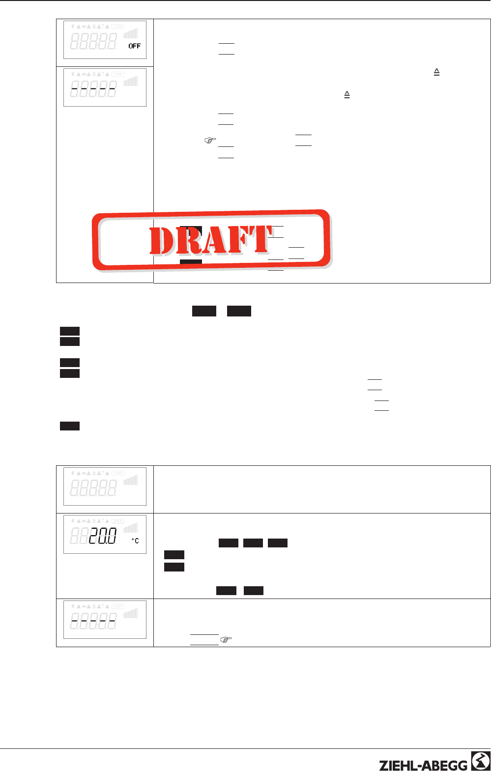
9.3.3 Functional diagrams pressure control condensers
Functional diagram for Mode 3.01 and 3.03 (Idealized principle diagram)
nM
50 %
100 %
I
Min.
Min. 0 % Max. = 100 %
12 bar
S
5 bar
R
17 bar 09.05.2007
v_diagramm_301_303_bar.vsd
nM Motor speed
S Setpoint
R Pband
I Actual value
Functional diagram for Mode 3.02 and 3.04 (Idealized principle diagram)
nM
50 %
100 %
I
Min. 0 % Max. = 100 %
35 °C
S
7 K
R
42 °C 09.05.2007
v_diagramm_302_304_c.vsd
nM Motor speed
S Setpoint
R Pband
I Actual value
Information
The factory default presets must be adapted to match the system conditions by a competent
person.
Operating Instructions AM-PREMIUM / AM-PREMIUM-W – model series Programming
L-BAL-E095-GB 1203 Index 004 Part.-No.
28/68
9.4 Pressure control airconditioning 4.01 ... 4.03
9.4.1 Base setup 4.01 ... 4.03
Base setup
Base setup
Mode
Mode
Mode selection e.g. 4.01
E2 Analog In
E2 Analog In
In all group 2 operating modes 4 ( 4.01 , 4.02 , 4.03 , ....) “E2 Analog In” factory setting
“DSG200 ”.
Selection sensor type: “DSG 50”, “DSG100*”, “DSG200”, “DSG300”*, “DSG500”,
“DSG1000”, “DSG2000”, “DSG4000”, “DSG6000 ”
(* no standard type).
With the use of not pre-programmed sensor types further settings are necessary.
Example with a 0 - 10 V sensor and 0 - 400 Pa measurement range (proportional
output signal):
E2 Analog In = 0 - 10 V, E2 Min. = 0.0 Pa, E2 Max. = 400 Pa, E2 Dezimal = 1, E2
Einheit = Pa
E2 Offset
E2 Offset
Sensor calibration with calibrated comparison device
E3 Function
E3 Function (only for special applications)
•External setpoint = Function
|
1E
|
by external signal (0 - 10 V) instead of
“Setpoint 1”. 0 - 10 V
0 - 100 % sensor measuring range.
•External manual operation via external signal (0 - 10 V) = Function
|
2E
|
Switch
over between settings on the device and external manual operation via digital
input (
IO Setup: fuction
|
7D
|
).
•Measurement value = function
|
7E
|
e.g. for limit indication, display in Info menu
“E3 Actual.”
Modes 4.02 and 4.03 with two sensors
The function is automatically jointly programmed in operating modes using 2 sensors.
The second analog input is thus allocated and additional function allocations are not
possible.
For 4.02 E3 Function at
|
6E
|
preprogrammed = sensor for setpoint lowering. Preprog-
rammed sensor type “KTY ”
For 4.03
|
E3
|
Function at
|
6E
|
preprogrammed = sensor for setpoint lowering.
- preprogrammed sensor type “BUS”
- measuring range -35.0...+65.0 °C
In “IO Setup”:
For enable “ON” / “OFF” via Bus:
- D1 function =
|
1D
|
- D1 Busmode = “ON”
For switch over setpoint 1 /2 via Bus:
- D2 function =
|
5D
|
,
- D2 Busmode = “ON”
Operating Instructions AM-PREMIUM / AM-PREMIUM-W – model series Programming
L-BAL-E095-GB 1203 Index 004 Part.-No.
29/68
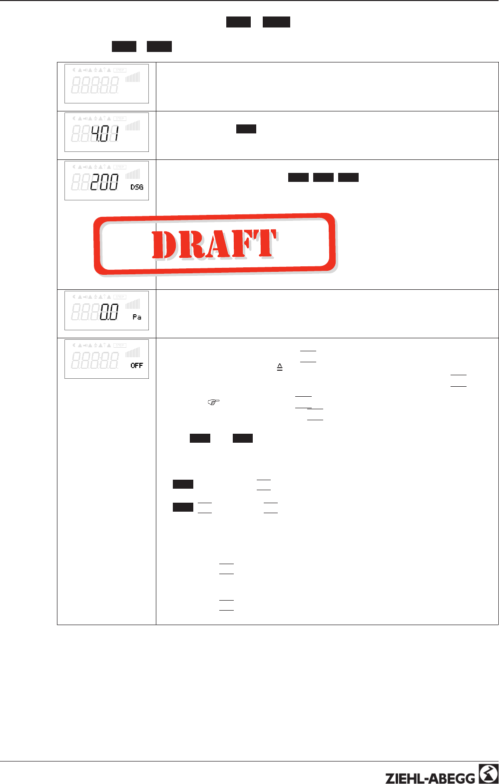
9.4.2 Setting for operation modes 4.01 ... 4.03
•4.01 pressure control, setpoint in Pa
•4.02 and 4.03 Pressure control for ventilation systems setpoint depending on outdoor temper-
ature
Setting
Setting
Setpoint1
Setpoint1
Setting range: in measuring range of sensor
Factory setting: 100 Pa
Setpoint2
Setpoint2
Setting “Setpoint 2” e.g. reduced value for night operation.
Switch over Setpoint 1/2 by external contact (as long as no allocation is carried out:
Display:
|
- - - - -
|
IO Setup).
Pband
Pband
Narrow control range = Short control times
Wide control range = Longer control times and more stable control
Setting range: in measuring range of sensor
Factory setting: 100 Pa
Min. Speed
Min. Speed
Setting range: 0 rpm... “Max. Speed”
Factory setting: 0 rpm
Max. Speed
Max. Speed
Setting range: Rated speed...0 rpm (takes priority over setting “Min. Speed”)
Factory setting: Rated speed
Manual mode
Manual mode
“OFF” = automatic control as function of the set parameters (Factory setting)
“ON” = automatic control without function, speed setting in menu “Speed manual”
Speed man.
Speed Manual mode
Manual speed setting without influence by the external signal.
Activation by menu “Manual mode” or external contact at digital input (
IO Setup).
Setting range: 0 rpm...Rated speed, Factory setting: 200 rpm
For information about deactivated regulation the adjusted value for manual speed is
indicated alternating with the actual value.
Operating Instructions AM-PREMIUM / AM-PREMIUM-W – model series Programming
L-BAL-E095-GB 1203 Index 004 Part.-No.
30/68
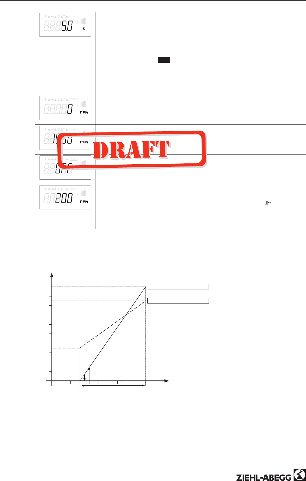
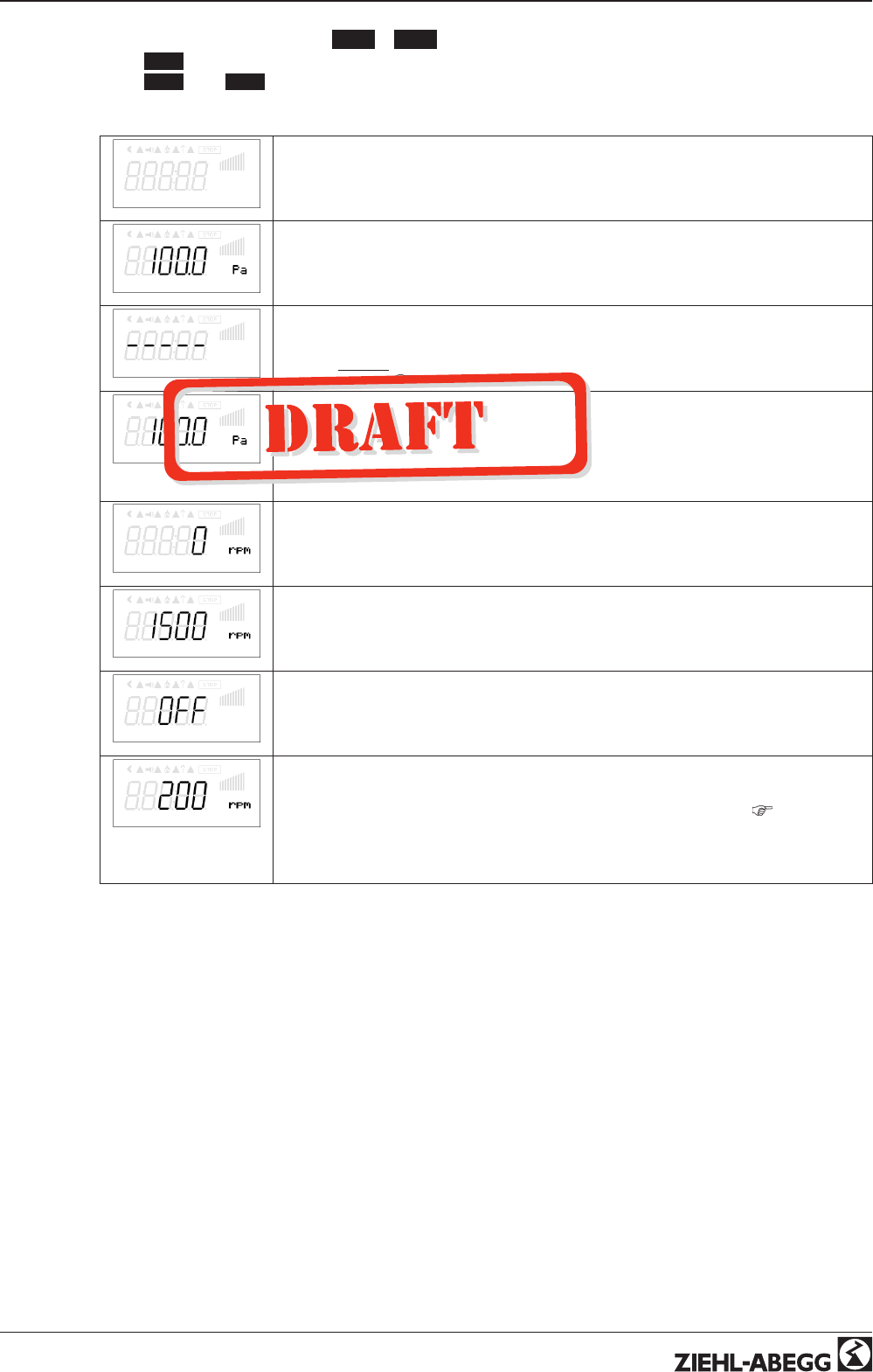
Additional menu item for mode 4.02 and 4.03 with outside-temperature dependent target-
setpoint.
Outside-temperature dependent target-setpoint
Außentemperatur
P-min SA
[Pa]
-15 °C
min. Temperatur
30 °C
T-Start
Sollwert 1
[Pa]
Sollwert 2
[Pa]
07.02.2007
v_sollwert_aussentemp_abhaengig_pa.vsd
S1 Setpoint1
S2 Setpoint2
P-Min SA Minimum pressure
T-min Minimum temperature
T-Start Setpoint reducing will start below this outside temperature
AT Outdoor temperature
An outside temperature compensation can be
activated (sensor connection “E2” = “Analog In
2”) when being operated as a pressure regula-
tion device.
An optimal building climate, e.g., can be
achieved through this. Through this function,
the set and active “Setpoint 1” or “Setpoint 2” is
automatically changed proportional to the
measured outside temperature (
Info: “Set-
point control”).
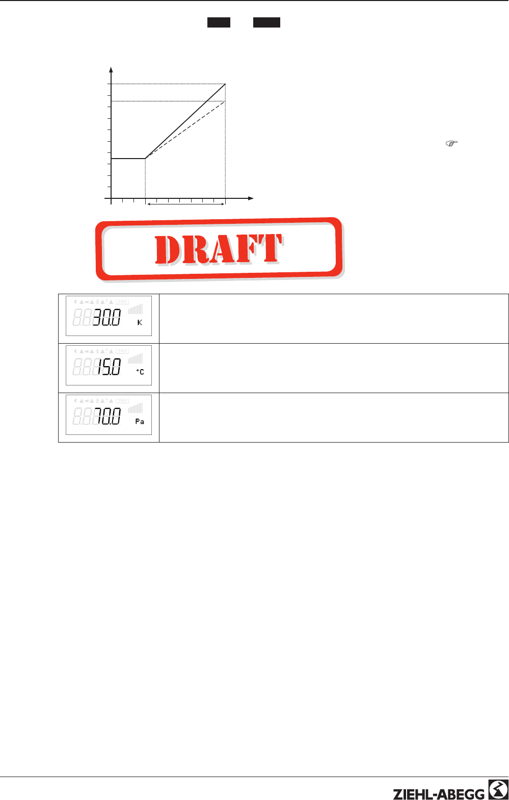
T-Band SA
T-Band SA
Temperature range in which the setpoint change continiously with outside temperature
T-Start SA
T-Start SA
Setpoint reducing will start below this outside temperature
P-Min SA
P-Min SA
Minimum pressure for very low outside temperature
Operating Instructions AM-PREMIUM / AM-PREMIUM-W – model series Programming
L-BAL-E095-GB 1203 Index 004 Part.-No.
31/68
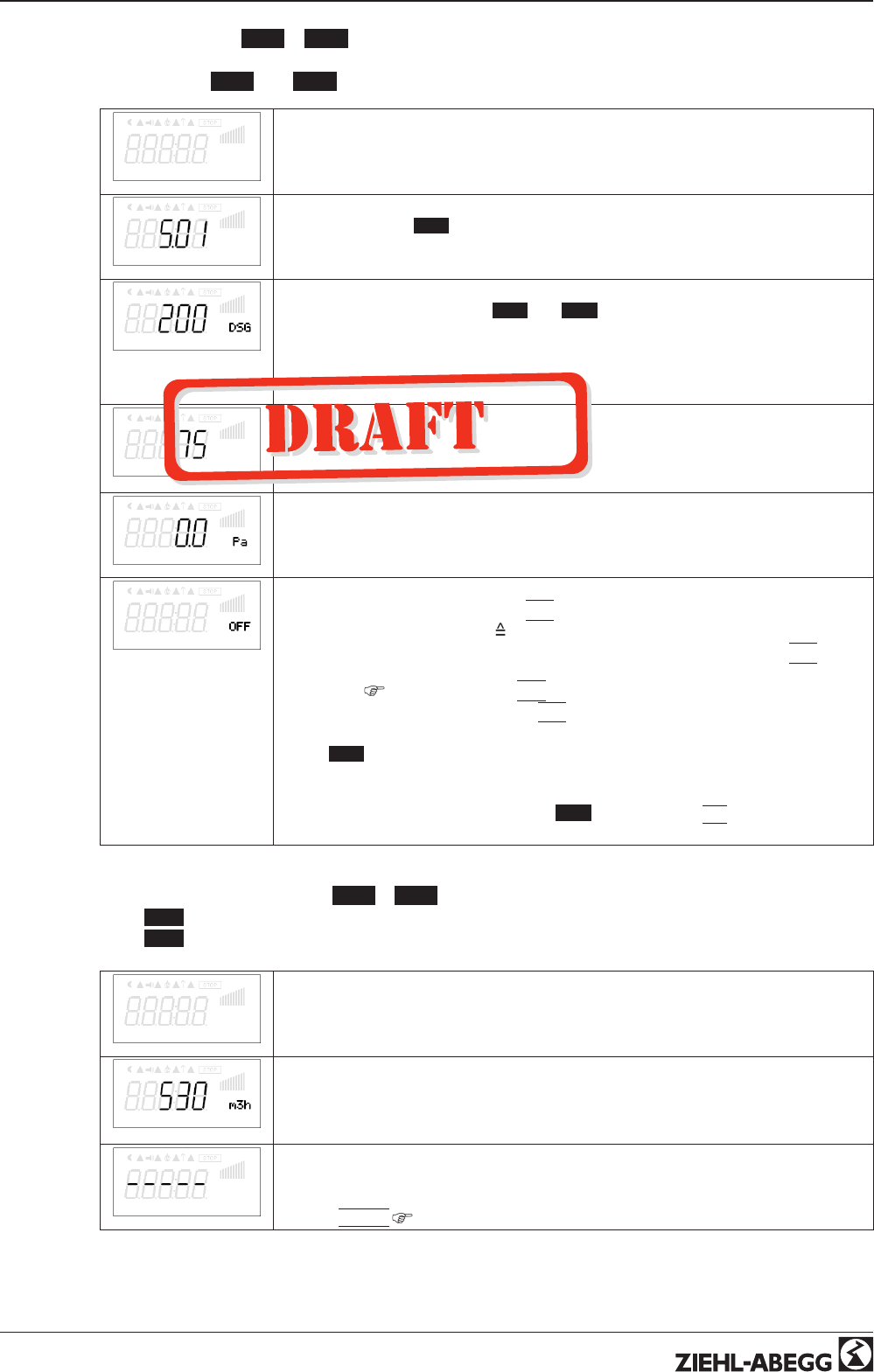
9.5 Volume control 5.01 ... 5.02
9.5.1 Basic setting 5.01 and 5.02
Setting
Base setup
Base setup
Mode
Mode selection e.g. 5.01
E2 Analog In
E2 Analog In
In all group operating modes 5 ( 5.01 and 5.02 ) “E2 Analog In” factory setting
“DSG200.”
Selection sensor measuring range: “DSG 50”, * “DSG100”, “DSG200”, * “DSG300”,
“DSG500”, “DSG1000”, “DSG2000”, “DSG4000”, “DSG6000”
(* no standard type).
K Factor
K Factor
Input of the “K factor” dependent on the fan (inlet duct).
setting range: 0...7.000
Factory setting: 75
E2 Offset
E2 Offset
Sensor calibration with calibrated comparison device
E3 Function
E3 Function (only for special applications)
•External setpoint = Function
|
1E
|
by external signal (0 - 10 V) instead of
“Setpoint 1”. 0 - 10 V
0 - 100 % setting range
•External manual operation via external signal (0 - 10 V) = Function
|
2E
|
Switch
over between settings on the device and external manual operation via digital
input (
IO Setup: fuction
|
7D
|
).
•Measurement value = function
|
7E
|
e.g. for limit indication, display in Info menu
“E2 Actual”
Modes 5.02 with two sensors
Modes with two sensors The function is automatically jointly programmed in operating
modes using 2 sensors. The second analog input is thus allocated and additional
function allocations are not possible. For 5.02 E3 Function at
|
6E
|
preprogrammed =
sensor for setpoint lowering. Pre-programmed sensor type “KTY”.
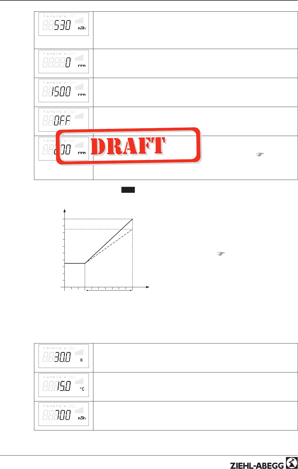
9.5.2 Setting for operation modes 5.01 ... 5.02
•5.01 Volume control, Setpoint in m
3
/h
•5.02 Volume control for ventilation systems setpoint depending on outdoor temperature.
Setting
Setting
Setpoint1
Setpoint1
Setpoint in m
3
/h (m
3
/s)
Setting range: depending on measuring range of sensor and “K factor”
Factory setting: 530 m
3
/h
Setpoint2
Setpoint2
Setting “Setpoint 2” e.g. reduced value for night operation.
Switch over Setpoint 1/2 by external contact (as long as no allocation is carried out:
Display:
|
- - - - -
|
IO Setup).
Operating Instructions AM-PREMIUM / AM-PREMIUM-W – model series Programming
L-BAL-E095-GB 1203 Index 004 Part.-No.
32/68
Pband
Pband
Narrow control range = Short control times
Wide control range = Longer control times and more stable control
Setting range: depending on measuring range of sensor and “K factor”
Factory setting: 530 m
3
/h
Min. Speed
Min. Speed
Setting range: 0 rpm... “Max. Speed”
Factory setting: 0 rpm
Max. Speed
Max. Speed
Setting range: Rated speed...0 rpm (takes priority over setting “Min. Speed”)
Factory setting: Rated speed
Manual mode
Manual mode
“OFF” = automatic control as function of the set parameters (Factory setting)
“ON” = automatic control without function, speed setting in menu “Speed manual”
Speed man.
Speed Manual mode
Manual speed setting without influence by the external signal.
Activation by menu “Manual mode” or external contact at digital input (
IO Setup).
Setting range: 0 rpm...Rated speed, Factory setting: 200 rpm
For information about deactivated regulation the adjusted value for manual speed is
indicated alternating with the actual value.
Additional menu item for mode 5.02 with outside-temperature dependent target-setpoint
Outside-temperature dependent target-setpoint
Außentemperatur
P-min SA
[m3/h]
-15 °C
min. Temperatur
30 °C
T-Start
Sollwert 1
[m3/h]
Sollwert 2
[m3/h]
07.02.2007
v_sollwert_aussentemp_abhaengig_m3h.vsd
S1 Setpoint1
S2 Setpoint2
P-Min SA Minimum air volume
T-min Minimum temperature
T-Start Setpoint reducing will start below this outside temperature
AT Outdoor temperature
An outside temperature compensation can be
activated (sensor connection “E2” to “Analog In
2”) when being operated as a air volume regu-
lation device.
An optimal building climate, e.g., can be
achieved through this. Through this function,
the set and active Setpoint 1/2 is automatically
changed proportional to the measured outside
temperature (
Info: “Setpoint control”).
T-Band SA
T-Band SA
Temperature range in which the setpoint change continiously with outside temperature
T-Start SA
T-Start SA
Setpoint reducing will start below this outside temperature
P-Min SA
P-Min SA
Minimum pressure for very low outside temperature
Operating Instructions AM-PREMIUM / AM-PREMIUM-W – model series Programming
L-BAL-E095-GB 1203 Index 004 Part.-No.
33/68
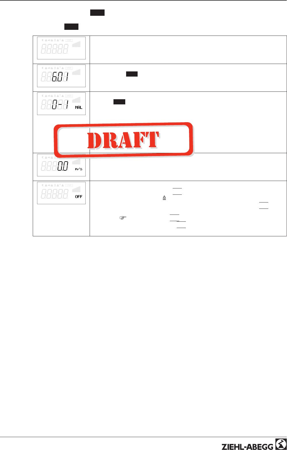
9.6 Air velocity control 6.01
9.6.1 Base setup 6.01
Base setup
Base setup
Mode
Mode
Mode selection 6.01
E2 Analog In
E2 Analog In
For mode 6.01 “E2 Analog In” factory setting to “MAL1”
Selection sensor measuring range: MAL1, MAL10
Alternative selection signal: 0 - 10 V, 0 - 20 mA, 4 - 20 mA.
The sensor measurement range must be entered in order to display the actual value
correctly. Example with a 0 - 10 V sensor and 0 - 5 m/s measurement range (propor-
tional output signal).
E2 Analog In = 0 - 10 V, E2 Min. = 0.0 m/s, E2 Max. = 5.0 m/s, E2 Decimals = 1, E2
Unit = m/s
E2 Offset
Sensor calibration with calibrated comparison device
E3 Function
E3 Function (only for special applications)
•External setpoint = Function
|
1E
|
by external signal (0 - 10 V) instead of
“Setpoint 1”. 0 - 10 V
0 - 100 % setting range
•External manual operation via external signal (0 - 10 V) = Function
|
2E
|
Switch
over between settings on the device and external manual operation via digital
input (
IO Setup: fuction
|
7D
|
).
•Measurement value = function
|
7E
|
e.g. for limit indication, display in Info menu
“E3 Actual.”
Operating Instructions AM-PREMIUM / AM-PREMIUM-W – model series Programming
L-BAL-E095-GB 1203 Index 004 Part.-No.
34/68
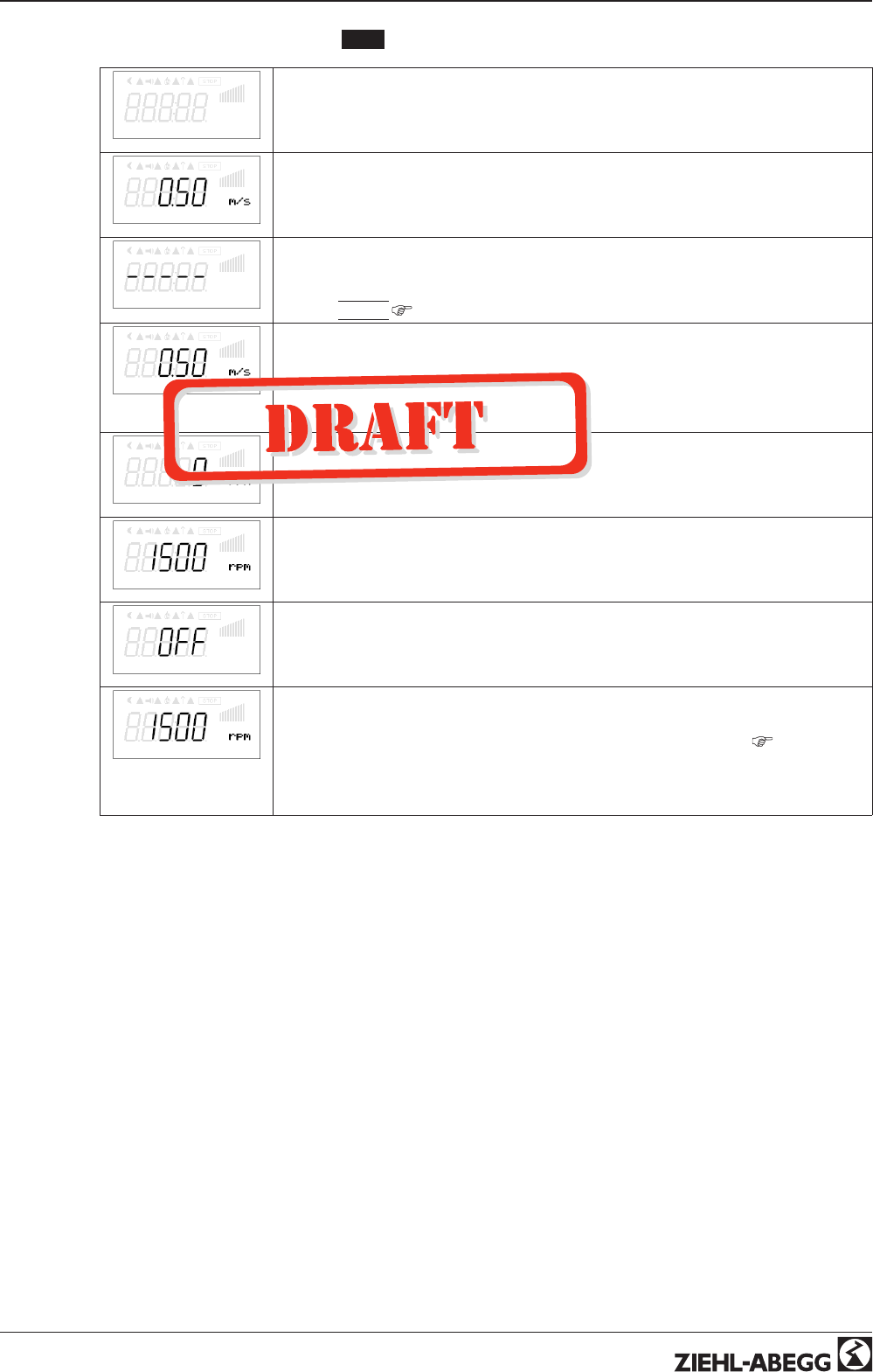
9.6.2 Settings for operation modes 6.01
Setting
Setting
Setpoint1
Setpoint1
Setting range: in measuring range of sensor
Factory setting: 0.50 m/s
Setpoint2
Setpoint2
Setting “Setpoint 2” e.g. reduced value for night operation.
Switch over Setpoint 1/2 by external contact (as long as no allocation is carried out:
Display:
|
- - - - -
|
IOSetup).
Pband
Pband
Narrow control range = Short control times
Wide control range = Longer control times and more stable control
Setting range: in measuring range of sensor
Factory setting: 0.50 m/s
Min. Speed
Min. Speed
Setting range: 0 rpm... “Max. Speed”
Factory setting: 0 rpm
Max. Speed
Max. Speed
Setting range: Rated speed...0 rpm (takes priority over setting “Min. Speed”)
Factory setting: Rated speed
Manual mode
Manual mode
“OFF” = automatic control as function of the set parameters (Factory setting)
“ON” = automatic control without function, speed setting in menu “Speed manual”
Speed man.
Speed Manual mode
Manual speed setting without influence by the external signal.
Activation by menu “Manual mode” or external contact at digital input (
IO Setup).
Setting range: 0...100 %, Factory setting: 100 %
For information about deactivated regulation the adjusted value for manual speed is
indicated alternating with the actual value.
Operating Instructions AM-PREMIUM / AM-PREMIUM-W – model series Programming
L-BAL-E095-GB 1203 Index 004 Part.-No.
35/68
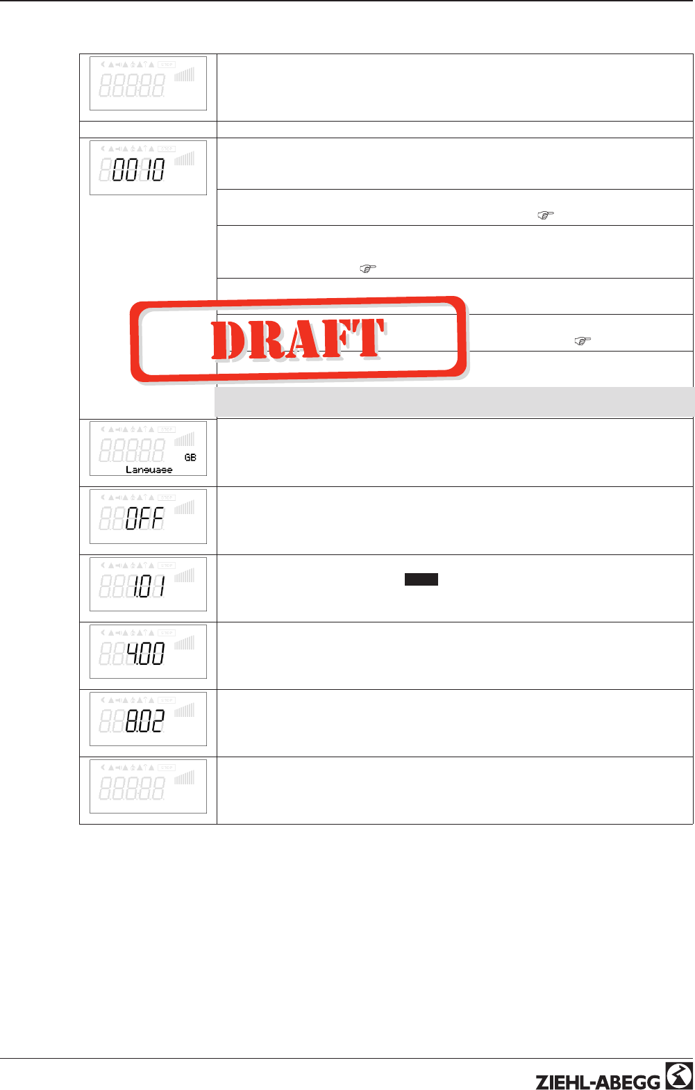
9.7 Menu group Start
Start
Start
PIN input
PIN input
The service menu for the installation can be protected against unintentional changes
by a pin code. With further pin codes putting back to pre-setting is possible.
PIN 0010
Opening “service menu”, if PIN-protection activated Menu (
menu structure).
PIN 1234
Opening “setting”.
if “set protection” = “ON” (
Controller Setup).
PIN 9090
Restore user setting.
PIN 9091
Save user setting (corresponds function “Save user setup” = “ON”
Controller Setup).
PIN 9095
Restore factory setting = delivery status.
Exception, the following parameters are not set back: Min. Speed, Max. Speed, all
settings in Motor Setup.
Language
Menu language by the factory set to English.
In this menu different national languages can be selected (GB = English, D = German
...).
Reset
Reset
Complete re-start of the device.
Mode
Mode
Query of the operating mode (e.g. 1.01 for speed controller).
ECblue Premium
ECblue Premium
Software version Modul.
Basic Version
Basic Version
software version motorcontroller.
SN: 09303459d336
Individual unit number.
Operating Instructions AM-PREMIUM / AM-PREMIUM-W – model series Programming
L-BAL-E095-GB 1203 Index 004 Part.-No.
36/68
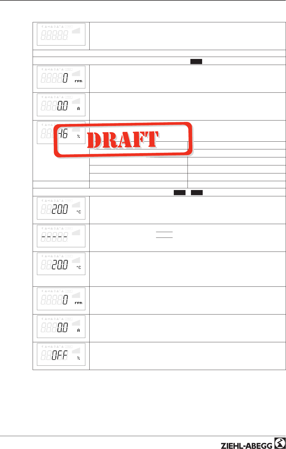
9.8 Menu group Info
Info
Menu group Info
Info for mode speed controller 1.01
Speed
Speed
Motor current
Display of motor current, different from the input current (metering precision approx.
+/-10%)
Set external1
The percentage corresponds to the internal actuation of the power component under
consideration of the settings “Min. speed” and “Max. speed”.
0 - 100 %
0 - 10 V, 10 - 0 V, 0 - 20 mA, 20 - 0 mA, 4 - 20 mA, 20 - 4 mA
Display: The device operates at:
Set “external1”Signal to “E2” / “GND”
Set “External2”Signal to “E3” / “GND”
Set “Intern1”Menu “Set Intern1”
Set “Intern2”Menu “Set Intern2”
Info for mode controller 2.01 ... 6.01
E2 Actual
Current actual value measured on the sensor 1.
Depending sensor-type in: mbr, m
3
/s, m/s, Pa, %, bar, m
3
/h, °C, V, mA, etc.
E3 Actual
For operation with two sensors display for “2 actual”.
If function not active, display
|
- - - - -
|
Setpoint1
Display of the active target value at which the device operates.
“Setpoint1” Menu “Setting”
“Setpoint2” Menu “Setting”
“Ext. Setpoint” = setting by external signal 0 - 10 V. With activated manual mode the
display constantly changes between actual value and value for manual mode.
Speed
Speed
Motor current
Motor current (deviating to input current)
Min. speed cut off
Momentarily status for minimum speed cut off
“ON” = switch off, if Setpoint (+/- “Min. speed cut off”) is reached.
“OFF” = no switch off that means operation with minimum rate of air.
Operating Instructions AM-PREMIUM / AM-PREMIUM-W – model series Programming
L-BAL-E095-GB 1203 Index 004 Part.-No.
37/68
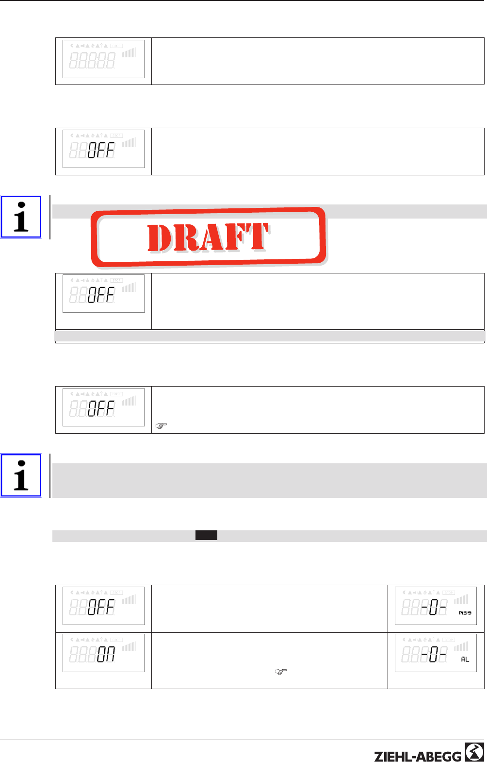
9.9 Controller Setup
Controller Setup
Controller Setup
9.9.1 PIN protection activate, PIN 0010
PIN Protection
The adjustments for the installation in the service level can be protected against
unintentional modifications. To do this, activate the “PIN protection” = “ON”.
In order to simplify the initial start-up operation, the service level in the factory setting is
free = “OFF” i.e. accessible without PIN 0010.
Information
After installation of the device has been carried out, “PIN-Protection” should be activated = “ON”
9.9.2 PIN protection activate, PIN 1234
Set protection
The “Settings” menu for the user’s basic settings (Setpoint, default value, min, max ..)
are freely accessible when using the factory settings (i.e. without “PIN”).
If necessary, these can also be protected against unauthorized modifications by using
a “PIN 1234” . For this, the settings protection must be programmed to “ON”. The
settings menu is then no longer visible without inputting a PIN!
Function only in combination with activated PIN-Protection!
9.9.3 Save user settings restore with PIN 9090
Save User Setup
The individually made device configurations (User Settings) can be saved and, with the
corresponding PIN input (9091), can be reestablished.
By entering PIN 9090 the individually made device configurations can be reestablished
(
Start - PIN Input).
Information
By entering “PIN 9095” in the “PIN” menu in the “start” menu-group, the device is entirely
reset to the pre-delivery condition.
Any changes that have been made to the settings are thus lost!
9.9.4 Sensor Alarm ON / OFF
Function only in controller mode ( 2.01 )!
For “E2 Analog In” and if activated for sensor 2 “E3 Analog In”.
In case of an interruption or short-circuit in the sensor conductor, or in case of measured values that
lie outside of the device’s measurement range, a time-delayed fault indication takes place.
Alarm sensors
With “Alarm Sensors” = “OFF” (factory setting). Indicated
sensor disturbances are displayed as “Message” alternating
to the actual value and stored in the menu of “Events”.
Sensor 1
Alarm sensors
With “AlarmSensors” = “ON” areindicated sensor disturban-
ces as “Alarm” alternating to the actual value and stored in
the menu of “Events”.
Indication via relays is possible (
IO Setup / function relay
outputs).
Sensor 1
Operating Instructions AM-PREMIUM / AM-PREMIUM-W – model series Programming
L-BAL-E095-GB 1203 Index 004 Part.-No.
38/68
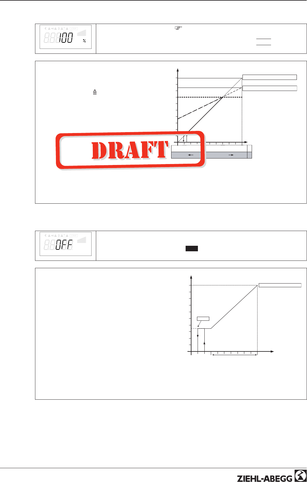
9.9.5 Limit
Limit
After allocation of a digital input (
IO Setup) an adjustable limitation of the modulation
can be activated via a digital input (“D1”, “D2”, ..).
As long as no allocation has been carried out “IO Setup”. Display:
|
- - - -
|
“Limit value” = max. possible modulation (e.g.
speed reduction during night operation by
time switch).
Setting range: “Limit” = “n-max” up to “n-min”.
Factory setting: 100 %
max. modulation, i.
e. no limit.
Setting depending on device tye in: % or rpm.
nM
50 %
100 %
D
P
Min.
L= 70% Min.= 0 % Max. = 100 %
50 %
R
0 %
I
S
100 %
I
L
L = 70% Min. = 35 % Max. = 85 %
10.05.2007
v_limit.vsd
Limit (idealized principle diagram)
nM Motor speed
L Limit
S Setpoint
R Pband
D Speed controller: setting signal
P P-controller: control deviation
9.9.6 Minimum speed cut off
Min. speed cut off
This function is primarily significant for installation of the device as a pure P Controller
in refrigeration and air-conditioning technology.
For operation mode speed controller 1.01 without function!
Msco = OFF (factory setting)
If no “Min. speed” is adjusted, the fan stops with
reaching the desired value.
If “Min. speed” is adjusted (e.g. 20%), then no dis-
connection of the fan takes place. I.e., always a
minimum ventilation is ensured (fan does not go
under setting “Min. speed”).
Msco. e.g. -2.0 K
It takes place a disconnection from setting “Min.
speed”to “0”, if the given difference is reached re-
lated to the desired value.
At a plus value (+) before reaching the desired value
At a minus value (-) after falling below the desired
value.
nM
50 %
100 %
I
Min.
Min. 35 % Max. = 100 %
20 °C
S
7 K
R
27 °C
-2.0 K
10.05.2007
v_min_luft_abschalt.vsd
Minimum speed cut off (idealized principle diagram)
nM Motor speed
S Setpoint
R Pband
I Actual value
Operating Instructions AM-PREMIUM / AM-PREMIUM-W – model series Programming
L-BAL-E095-GB 1203 Index 004 Part.-No.
39/68
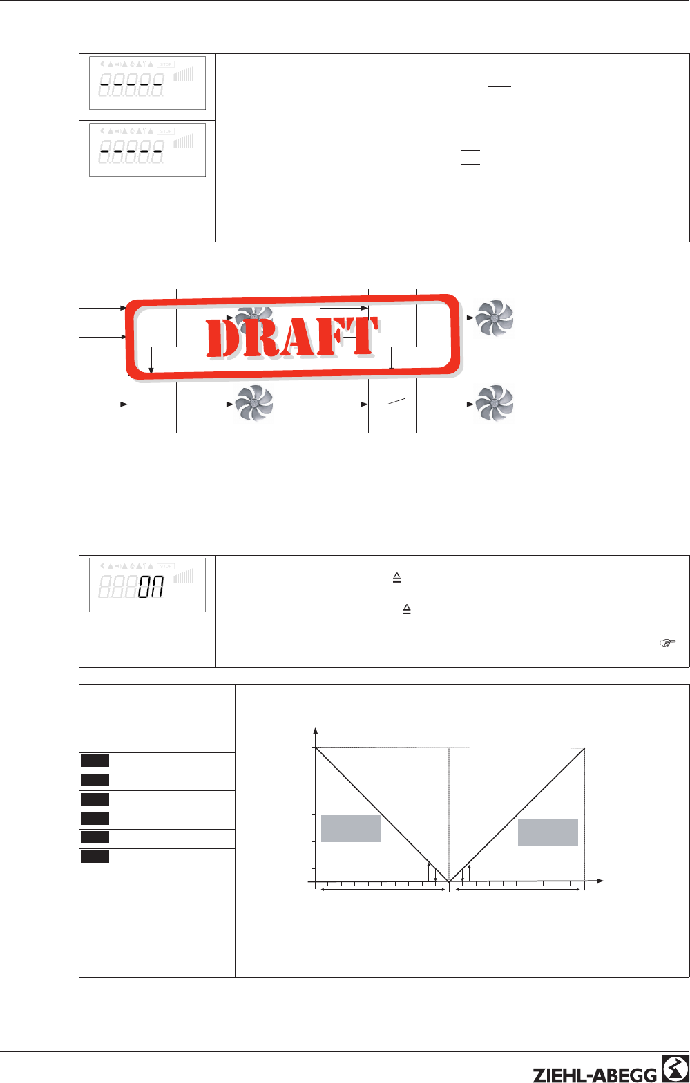
9.9.7 Second Group
Group 2 ON value
Second group “indirectly controlled” (picture A)
Analog output “AnalogOut 1” in IO Setup function
|
5 A
|
= group control is programmed.
This output is employed as the default signal for a speed controller. If the default signal
or the regulation deviation exceeds the group 2 switch-on point, group 1 is reduced to
“n-min group 2”. Starting here, both groups run parallel at maximum power.
Second group “100 % energized” (picture B)
Relay output (K1 or K2) in IO Setup function
|
8K
|
= group control is programmed. A
contactor is triggered via this relay contact, which directly switches the fans of the
second group to mains voltage. If the default signal or the regulation deviation exceeds
the “Group 2 ON value” switch-on point, the relay for the second group switches on and
the speed of the first group is lowered to an adjustable minimum value. After that, the
speed of the first group increases back up to maximum.
nmin at Group2
Controller
Master
N
Si/ Se
A
Controller
Slave
Si 0-10 V
N
0 .. 100 %
1
2
0 .. 100 % Controller
Master
N
Si/ Se
B
C
ON / OFF
N
0 / 100 %
1
2
0 .. 100 %
10.05.2007
v_zweite_gruppe.vsd
N Line
Si Signal
Se Sensor
C Contactor
9.9.8 Reverse action of the control function
Val>Set=n+
For the effect of the regulation there are two functions:
•ON for “Val > Set = n+”
increasing Fanlevel for increasing actual value over
Setpoint.
•OFF for “Val > Set = n+”
increasing Fanlevel for decreasing actual value
below Setpoint.
For special applications an external switch over of the control function is possible (
IO Setup).
Factory setting depending
on selected mode
Example for temperature control (Idealized principle diagram)
Mode Controller
function
nM
100 %
I
SR
R
OFF ON
10.05.2007
v_umkehr_regelfunktion.vsd
nM Motor speed
R Pband
S Setpoint
I Actual value
OFF for Val > Set = n+ = heating function
ON for Val > Set = n+ = cooling function
1.01 non
2.01 ... ON
3.01 ... ON
4.01 ... OFF
5.01 ... OFF
6.01 ... OFF
Operating Instructions AM-PREMIUM / AM-PREMIUM-W – model series Programming
L-BAL-E095-GB 1203 Index 004 Part.-No.
40/68
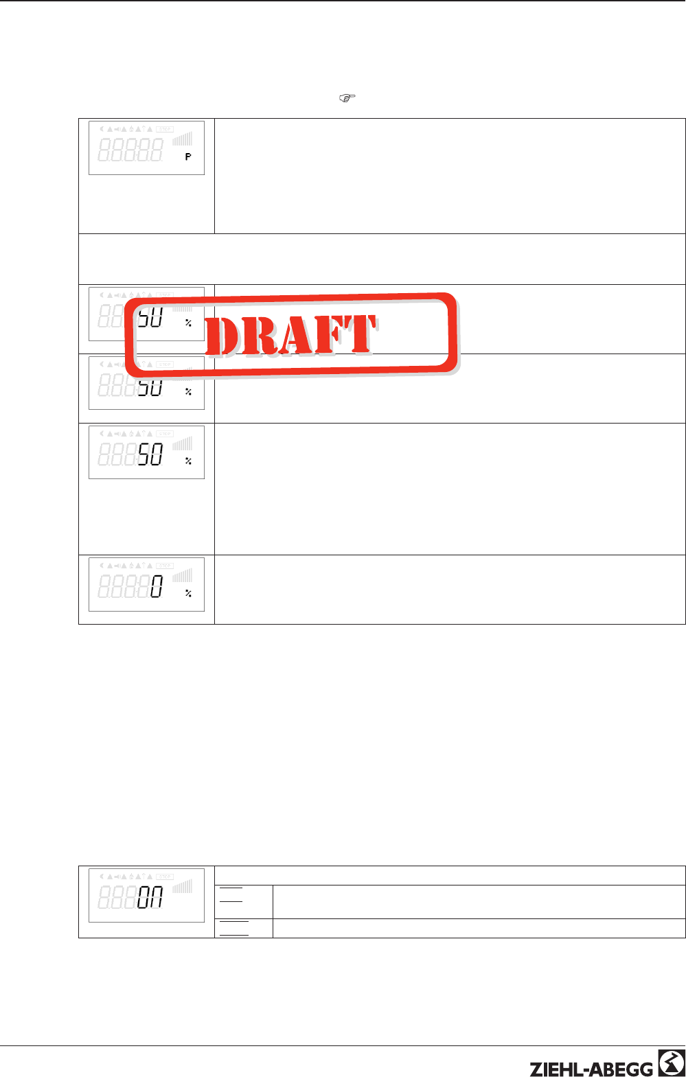
9.9.9 Controller configuration
The “controller configuration” is automatically carried out during selection of the application related
mode of operation (Base setup). The factory presets in accordance with the mode of operation are
based on many years of experience, which is suitable for many applications. Under special circum-
stances, these can be individually adapted (
Menu group “setting”).
Type of control
The type of control determines the method with which the controlled value behaves in
case of a difference between the target and current values. For this, the control
technology has standard algorithms, which consist of a combination of three methods:
Selection P, PID:
•P control (Proportional component, proportion of the absolute deviation)
•I control (Integral component, proportion of the sum of all deviations)
•D control (Differential component, proportion of the last difference)
With pure P controllers (controller type P), the following described settings do not have any function.
If needed, the most suitable combination for the respective control system can be determined from these
proportions.
KP
P-component = reaction time
Setting range: 0 - 200 %
smaller = more slowly
bigger = faster
KI
I-component = accuracy, correction time
Setting range: 0 - 200 %
bigger = faster
smaller = more slowly
KD
D-component
More “D-component” causes more stability by a clean actual value signal with shorter
correction times
By a actual value signal with a superposition should be done to attitude without “D-
component” → 0 %
Setting range: 0 - 200 %
value smaller = less “D-component”
value higher = more “D-component”
TI
Integration time = correction time
Setting range: 0 - 200 %
smaller = faster
bigger = more slowly
9.9.10 Data on the total control deviation
The total control deviation is comprised of the sum of the control deviations for performance quantities
and work quantities combined and refers to the specified areas.
In direct reference to the acquired input and controlled variables, the maximum deviation to the target
value is < ± 5 %. By activating the menu-assisted adjustment, the total control deviation can be
reduced to a value of < ± 1 %.
For indirect reference of the acquired input value to the controlled variable, i.e., two physical variables
still need to be converted, the deviation can be reduced to < ± 5 % through adjustment.
In the case of an internal default value through the integrated or external terminal, the control deviation
remains at < ±0.5%.
9.9.11 LED Mode
LED Mode
For motor sizes “D” and “G” there is a status LED in the cover of the controller housing.
|
ON
|
Status LED in ECblue active i.e. operating conditions are indicated by flash
code (factory setting).
|
OFF
|
Status LED not active, i.e. always OFF.
Operating Instructions AM-PREMIUM / AM-PREMIUM-W – model series Programming
L-BAL-E095-GB 1203 Index 004 Part.-No.
41/68
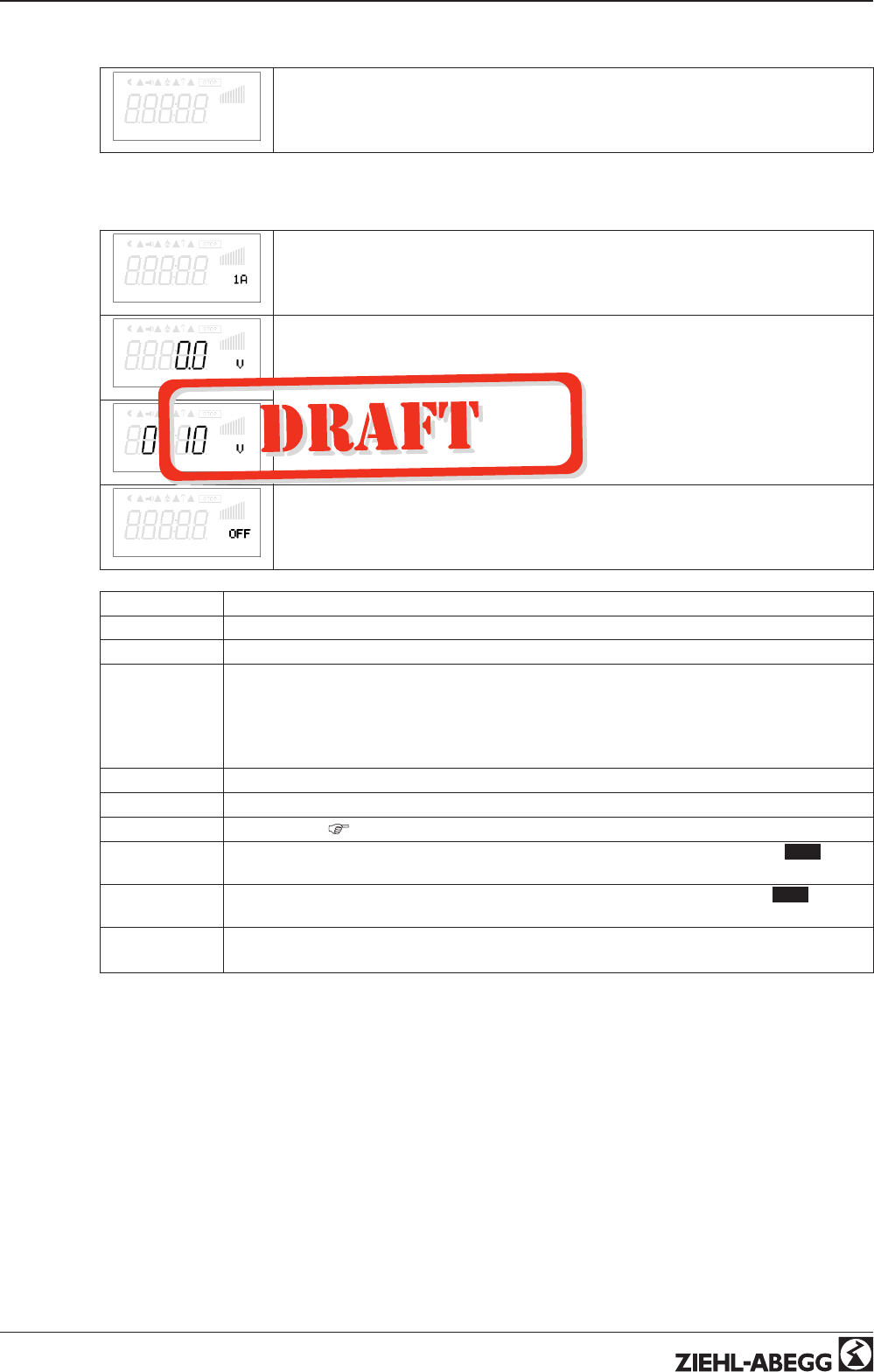
9.10 IO Setup
IO Setup
IO Setup
9.10.1 Analog-Output “A”
A Function
The analog outputs 0 - 10 V can be allocated with various functions.
Terminals “A” - “GND” = Analog Out (I
max
10 mA)
A min.
With the attitudes “A min” and “A max” the characteristic of the output voltage can be
adapted.
Setting range: “A min.” = 0 - 5 V, “A max.” = 10 - 5 V
Factory setting: “A min.” = 0 V, “A max.” = 10 V
A max.
A Inverting
With the attitudes “A Inverting” the output voltage can inverted.
Factory setting: “A Inverting” = “OFF”
Function Description
OFF without function
1A Constant voltage +10 V (factory setting)
2A Proportional the internal control of modulation with consideration “Min. speed” and “Max.
speed” setting.
•for enable “OFF” it goes back to 0 V
•for motor fault the output signal remains for a slave controller (“Master-Slave”
combination).
3A proportional input “E2”
4A proportional input “E3”
5A Group control (
Controller Setup - second group)
6A Control output 2 increasing modulation at actual value > Set = cooling (only mode 2.03
temperature controller with additional functions).
7A Control output 2 incresing modulation at actual value < Set (Heating) only mode 2.03 temper-
ature controller with additional functions).
9A Output speed
ratio: actual speed / rated speed (for 10 V actual speed = rated speed)
Operating Instructions AM-PREMIUM / AM-PREMIUM-W – model series Programming
L-BAL-E095-GB 1203 Index 004 Part.-No.
42/68
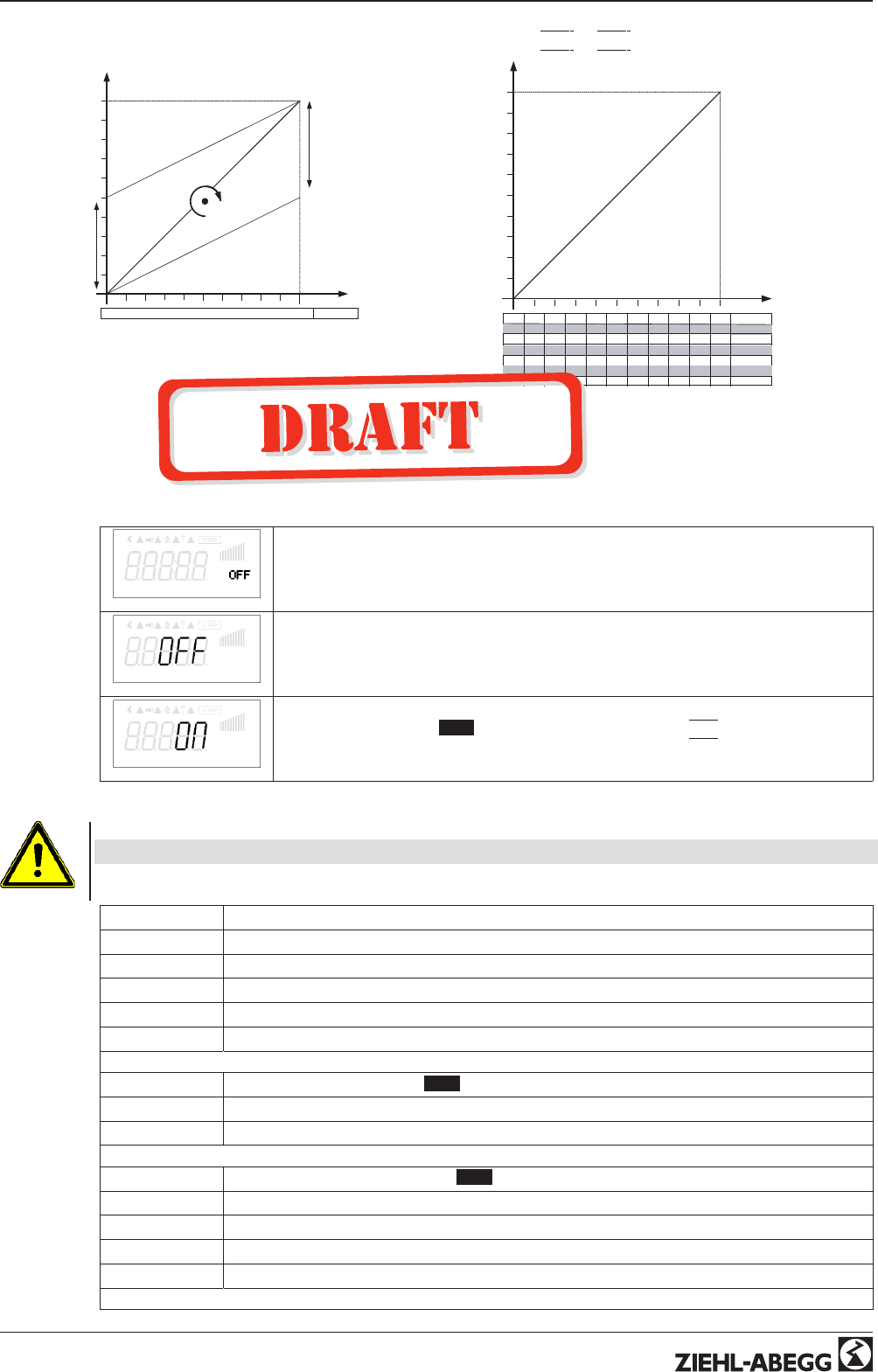
A1 Function “A min.” and “A max.”
Analog
Out
5 V
10 V
Funktion
0 50 100 0 -100 %
A max: 10 – 5V
A min: 0 – 5V
16.03.2007
v_a1_funktion_amin_amax.vsd
A1 Function
|
3A
|
/
|
4A
|
5 V
10 V
Signal
0 1 2 3 4 5 6 7 8 9 10
10 9 8 7 6 5 4 3 2 1 0
0 2 4 6 8 10 12 14 16 18 20
20 18 16 14 12 10 8 6 4 2 0
4 5,6 7,2 8,8 10,4 12 13,6 15,2 16,8 18,4 20
20 18,4 16,8 15,2 13,6 12 10,4 8,8 7,2 5,6 4
0 – 10 V
10 – 0 V
0 – 20 mA
20 – 0 mA
4 – 20 mA
20 – 4 mA
-27 -16.8 -6.6 3.6 13.8 24 34,2 44.4 54.6 64.8 +75 TF.. (KTY)
16.03.2007
v_a1_funktion_3a_4a.vsd
9.10.2 Digital inputs “D1” / “D2” (E1)
9.10.2.1 Menu overview
D1 Function
The digital inputs Digital In 1 (D1) and Digital In 2 (D2) can be allocated with various
functions.
Activation via floating contacts (a low voltage of approx. 24 V DC is connected).
D1 Inverting
Inverting “D1” and “D2” possible
D1 Busmode
With networking the digital inputs can be replaced by control over bus.
With mode of operation 4.03 pre-setting of “D1” and “D2” is
|
ON
|
.
Attention!
Never apply line voltage to the digital input!
Function Description
OFF No function
1D Enable (remote control) “ON” / “OFF”
2D External error
3D “Limit” ON / OFF
4D Switch over “E1” / “E3”
For mode speed controller 1.01
5D Switch over “Setpoint Intern1” / “Setpoint Intern2”
6D Switch over “Intern” / “Extern”
For modes as controller higher 2.01
5D Switch over “Setpoint1” / “Setpoint2”
6D Switch over “Intern” / “Extern”
7D Switch over “automatic control” / “Speed manual”
8D Switch over control function (e.g. “heating” / “cooling”)
Operating Instructions AM-PREMIUM / AM-PREMIUM-W – model series Programming
L-BAL-E095-GB 1203 Index 004 Part.-No.
43/68
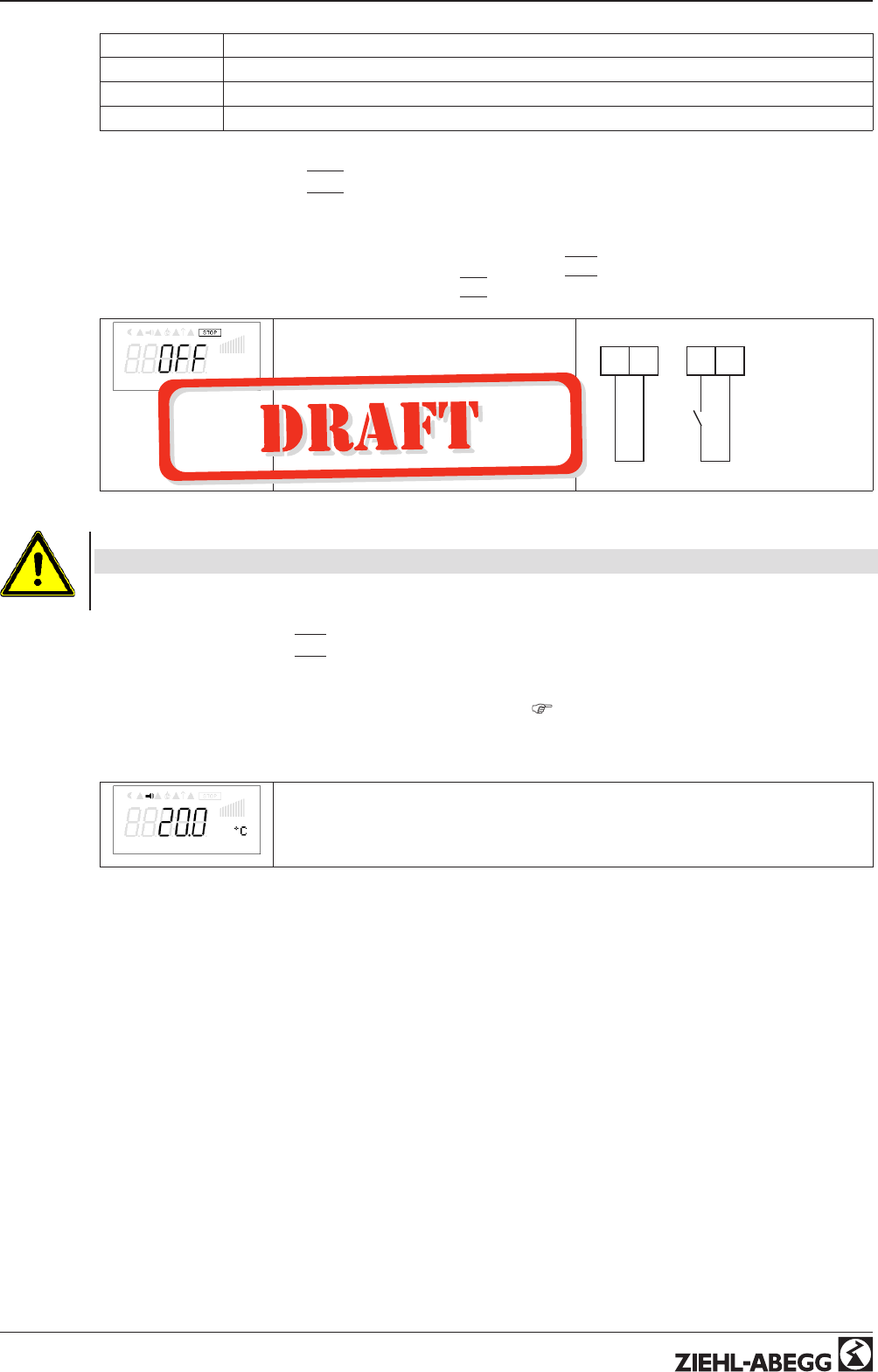
10D “Reset”
11D Setting Max. Speed “ON” / “OFF”
13D Switch over direction of rotation “right” / “ left”
14D “Freeze function” = maintain momentary modulation value
9.10.2.2 Enable ON/OFF function
|
1D
|
Remote ON/OFF (electronic disconnection) and Reset after a motor malfunction via floating contact.
The power section is electronically disconnected. Operation of the device is still possible after
pressing the “ESC” hotkey combination in switched-off condition. Signal- in and outputs remain active.
•A programmed alarm relay (factory set “K1 function” =
|
2 K
|
) does not report the switch-off.
•A programmed operation indicator relay (
|
1K
|
) reports the switch-off.
Display STOP for switch OFF
•Controller “ON” for closed contact
(factory setting).
•Controller “OFF” with opened con-
tact
When inverting in reverse i.e. equipment
“OFF” with closed contact.
24V D1 24V D1
Digital IN 1 Digital IN 1
ON
25.06.2007
v_1d_24v_freigabe.vsd
OFF
Attention!
No disconnection (isolation) when turned off, in accordance with VBG4 §6)!
9.10.2.3 External fault Function
|
2D
|
Connecting an external alarm indication (via floating contact). The device continues to work un-
changed during an external indication to the digital input; the alarm symbol appears in the display.
This indication can be issued via the relay contacts (K1) (
IO Setup function K1).
•Indication during closed contact (factory setting): “D1 Inverting” = “OFF ”
•Indication during opened contact: “D1 Inverting” = “ON ”
Actual value
Alarm symbol for indication “External fault”
Operating Instructions AM-PREMIUM / AM-PREMIUM-W – model series Programming
L-BAL-E095-GB 1203 Index 004 Part.-No.
44/68
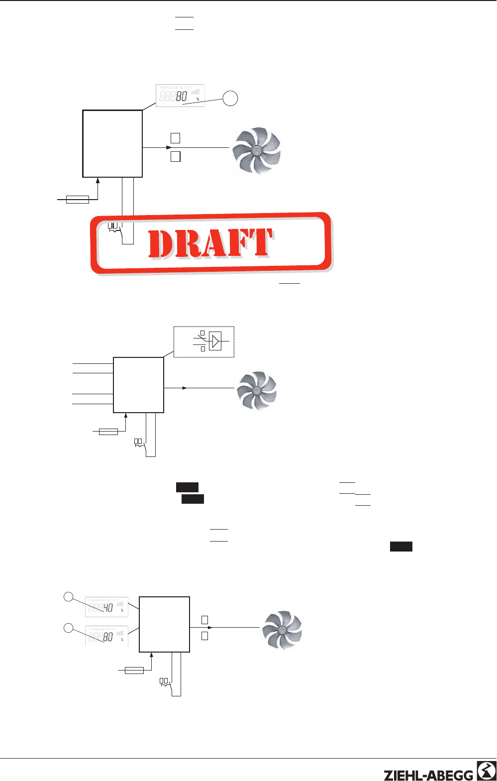
9.10.2.4 Limit ON / OFF, Function
|
3D
|
The value for “Limit” adjusted in the Controller Setup, is activated over a digital input.
Contact e.g. at ditgital input “Digital In 1” (depending on device type at terminals “D1” - “D1”or “D1” -
“24 V”).
For “D1” Inverting“OFF”, limitation active at closed contact.
Controller
24V
D1 D1
10
n = 0- 80 %
1
0
- - - - -
n = 0- 100 %
10.05.2007
v_3d_limit.vsd
1
1 Setting “Limit” (depending on device type in: %, Hz, rpm)
9.10.2.5 Switch over Input signal “E2” / “E3”, Function
|
4D
|
Switch over between Input signal 1 (Analog In 1 terminal “E2”) and input signal 2 (Analog In 3 terminal
“E3”).
Contact at digital input e.g. “Digital In 1”= terminals “D1” - “24 V”
10
n = 0- 100 %
0
1
Si 1
Si 2
E2
GND
E3
GND
Si 1
Si 2
17.09.2009
v_4d_umschaltung_e2_e3.vsd
Controller
24V D1
Si 1 Signal 1
Si 2 Signal 2
For mode speed controller ( 1.01 ) Base setup for “E3 Analog In”:
|
1E
|
necessary.
For modes controller (higher 2.01 ..) Base setup for “E3 Analog In”:
|
7E
|
necessary (as far as
otherwise does not occupy).
9.10.2.6 Set 1/2 or Setpoint 1/2, Function
|
5D
|
Switch over between “Set Intern1” and “Set Intern2” (for speed controller 1.01 )
Contact e.g. at ditgital input “Digital In 1” (depending on device type at terminals “D1” - “D1”or “D1” -
“24 V”).
Controller
24V
D1 D1
10
n = 40 %
1
n = 80 %
0
- - - - -
- - - - -
11.05.2007
v_5d_vorgabe_intern_1_2.vsd
2
1
1 Setting “Set Intern1” (depending on device type in: %, Hz, rpm)
2 Setting “Set Intern2” (depending on device type in: %, Hz, rpm)
•“D1 Inverting” = “OFF”: “Set Intern1” at
opened contact / “Set Intern2” at closed
contact.
•“D1 Inverting” = “ON”: “Set Intern1” at
closed contact / “Set Intern2” at opened
contact.
Operating Instructions AM-PREMIUM / AM-PREMIUM-W – model series Programming
L-BAL-E095-GB 1203 Index 004 Part.-No.
45/68
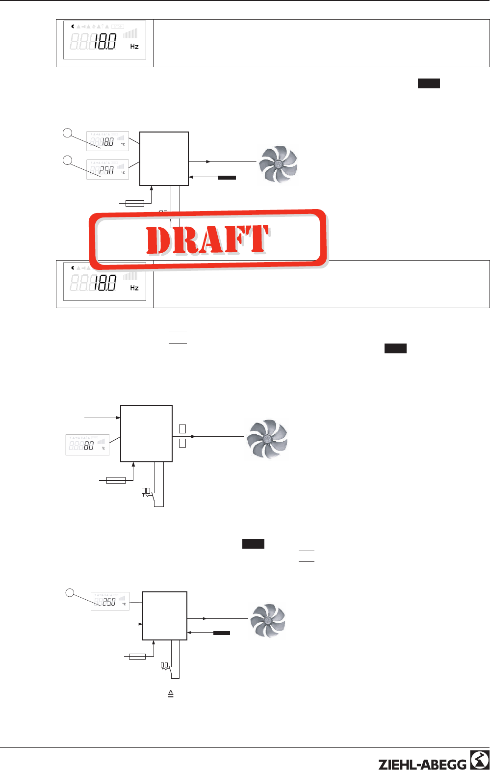
Frequency
Operation with “Set Intern2” is signalized by the moon symbol for reduced operation.
“Set extern1” under “settings” must be programmed to “OFF”.
Switch over between “Setpoint1” and “Setpoint2” (for modes as controller higher 2.01 )
Contact e.g. at ditgital input “Digital In 1” (depending on device type at terminals “D1” - “D1”or “D1” -
“24 V”).
Controller
10
n = 0 – 100 %
- - - - -
- - - - -
Sensor
11.05.2007
v_5d_sollwert_1_2.vsd
2
1
24V
D1 D1
1 Setting “Setpoint1”
2 Setting “Setpoint2”
•“D1 Inverting” = “OFF”: “Setpoint1” =
18 °C at opened contact / “Setpoint2” =
25 °C at closed contact.
•“D1 Inverting” = “ON”: “Setpoint1” = 18
°C at closed contact / “Setpoint2” = 25
°C at opened contact.
E1 Actual
Operation with “Setpoint2” is signalized by the moon symbol for reduced operation.
9.10.2.7 Intern / Extern Function
|
6D
|
Switch over between Set Intern and Set Extern (for mode speed controller 1.01 ). “Set extern1”
under settings must be programmed to “OFF”.
Contact e.g. at ditgital input “Digital In 1” (depending on device type at terminals “D1” - “D1”or “D1” -
“24 V”).
Controller
24V
D1 D1
10
n = 40 %
n = 80 %
Si 40 %
- - - - -
E2
16.11.2009
v_6d_vorgabe_intern_extern_e2.vsd
1
0
Si Signal
1 Setting “Set Intern1” (depending on device type in: %, Hz, rpm)
•“D1 Inverting” = “OFF”: “Set Intern1” at
opened contact / “Setting Extern” at
closed contact.
•“D1 Inverting” = “ON”: “Set Intern1” at
closed contact / “Set Extern” at opened
contact.
“Setpoint1” / “external Setpoint” (modes 2.01 )
Under Base setup “E3 function” programmed to function
|
1E
|
for “external setpoint” .
Contact at digital input e. g. “Digital In 1” = “D1” - “24 V”
Controller
24 V D1
10
n = 0 – 100 %
- - - - -
Se
ES E3
16.09.2009
v_6d_sollwert1_externer_sollwert_e3.vsd
1
1 Setting “Setpoint1”
ES External Setpoint e.g. 5 V
23.8°C
Se Sensor
•“D1 Inverting” = “ON”: Setting at the unit
at opened contact / Signal Extern at
closed contact
•“D1 Inverting” = “OFF”: Setting at the
unit at closed contact / Signal Extern at
opened contact
Operating Instructions AM-PREMIUM / AM-PREMIUM-W – model series Programming
L-BAL-E095-GB 1203 Index 004 Part.-No.
46/68
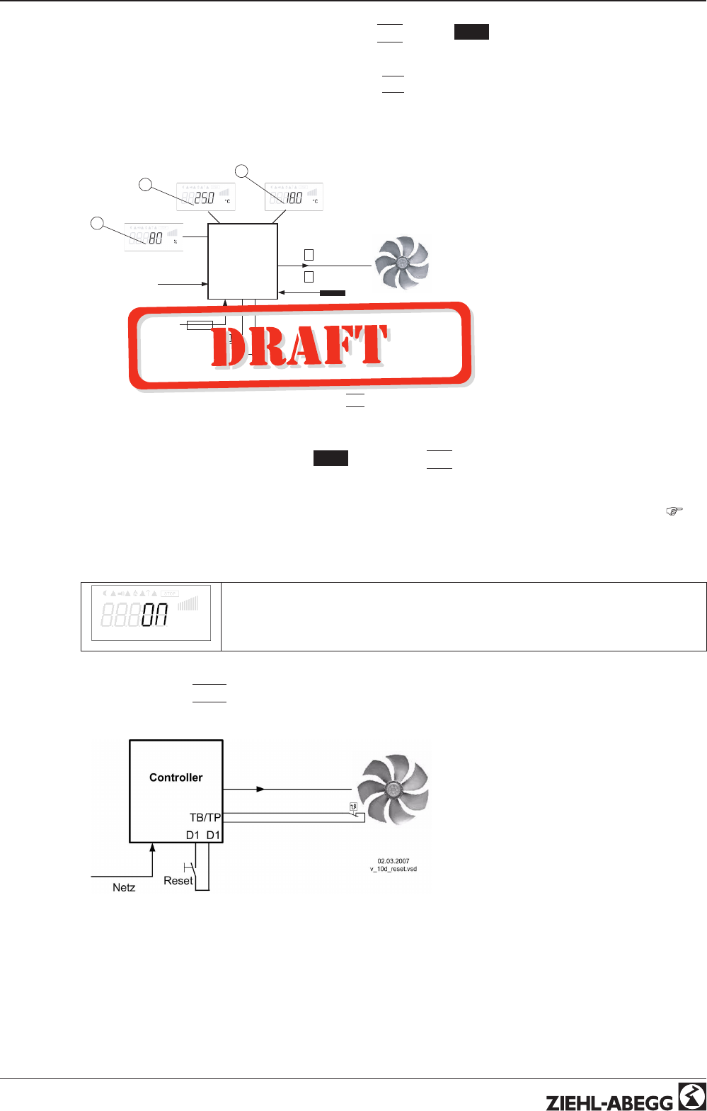
9.10.2.8 Automatic control / speed manual, Function
|
7D
|
(mode 2.01 )
Switch over between automatic control to set target value (depending on the activation: “Setpoint1”,
“Setpoint2”) and the default for “manual operation” set at the device.
If for Analog In 2 “E3 function” is programmed to
|
2E
|
switch over between “Setpoint1” or “Setpoint2”
and external manual operation. With activated manual mode the display constantly changes between
“actual value” and value for “manual mode”.
Contact at digital input e.g. “Digital In 1”
Controller
24 V D1
10
n = 0 -100 %
1
n = 80 %
0
- - - - -
- - - - - - - - - -
Se
E2
ES E3
16.09.2009
v_7d_regelung_hand_e2_e3.vsd
3
2
1
1 Setting “Setpoint1”
2 Setting “Setpoint2”
3 Setting “Speed manual” (depending on device type in: %, Hz, rpm)
EH Signal for Manual mode extern, E3 Function =
|
2E
|
Se Sensor
•“D1 Inverting” = “OFF” Automatic
control at opened contact / manual
operation at closed contact.
•“D1 Inverting” = “ON”: Automatic control
at closed contact / manual operation at
opened contact.
9.10.2.9 Reverse action of control function ( 2.01 ), Function
|
8D
|
Switchover between: Increasing modulation during increasing actual-value and increasing modulation
during sinking actual-value.
The factory presets for the “Control function” are dependent on the selected mode of operation (
Controller Setup - reverse operation of the control function).
When switching over via a digital input, the device works with the opposite function than the one set
there!
Val>Set=n+
Settings in Controller Setup
9.10.2.10 Reset, Function
|
10D
|
Complete re-start of the device.
Contact at digital input e.g. “Digital In 1”
•For “D1 Inverting” = “OFF” both
terminals “D1”- “24 V” in normal
operation interrupted. Reset after fault by
short close.(For “Inverting” = “ON”
reverse function).
Operating Instructions AM-PREMIUM / AM-PREMIUM-W – model series Programming
L-BAL-E095-GB 1203 Index 004 Part.-No.
47/68
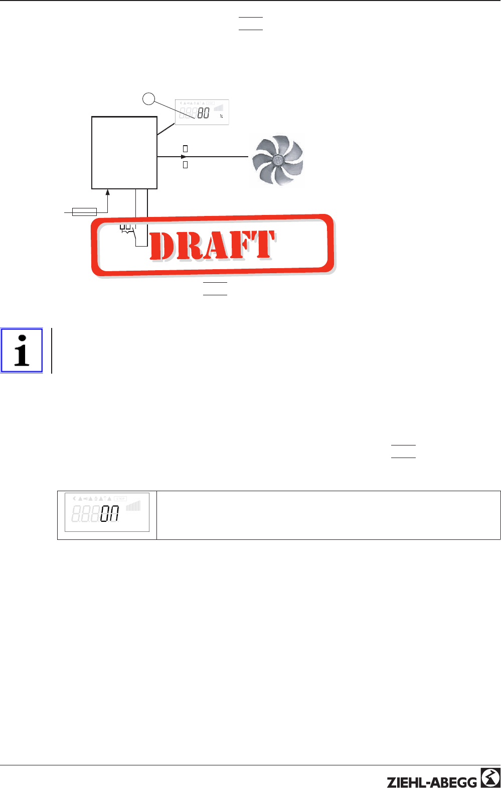
9.10.2.11 Setting Max. Speed ON / OFF function
|
11D
|
The value for “Max Speed” adjusted in menu “Settings”, is activated over a digital input. I.e. the unit
works independently of the controller function firm with this value.
Contact e.g. at ditgital input “Digital In 1” (depending on device type at terminals “D1” - “D1”or “D1” -
“24 V”).
15.05.2009
v_11d_max_drehzahl.vsd
Controller
24V
D1 D1
= 80 %
10
- - - - -
1
0
= 0 .. 100 %
1
1 Setting “Max. Speed” (depending on device type in: %, Hz, rpm)
•“D1 Inverting” = “OFF”: “Max. Speed”
active at closed contact
•“D1 Inverting” = “ON”: “Max. Speed”
active at opened contact
9.10.2.12 Direction of rotation, Function
|
13D
|
Switch over “clockwise” rotation and “counterclockwise” rotation. When switching over via a digital
input, the device works with the opposite function than the one set in motorsetup.
Information
If the rotary direction is reversed with an available modulation, it is initially reduced to “0”
(disconnected) and subsequently increased back to the default value.
Contact e.g. by digital input “Digital In 1” for factory setting “ clockwise rotation.”
•“D1 Invertierung” = “OFF”: “Clockwise” at opened contact / “Counterclockwise” at closed
contact.
•“D1 Invertierung” = “ON ”: “Counterclockwise” at opened contact / “Clockwise” at closed contact.
9.10.2.13 “Freeze function” = maintain momentary modulation value, Function
|
14D
|
The device continues to work so long independently of the controller function with the momentary
value of the modulation and / or speed as activated over the digital input.
Freeze
Message indicated alternating with the active value “Freeze Function”
Contact at digital input e.g. “Digital In 1”
“D1 Inverting” = “OFF”: “Freeze function” at closed contact activ
“D1 Inverting” = “ON”: “Freeze function” at opened contact activ
Operating Instructions AM-PREMIUM / AM-PREMIUM-W – model series Programming
L-BAL-E095-GB 1203 Index 004 Part.-No.
48/68
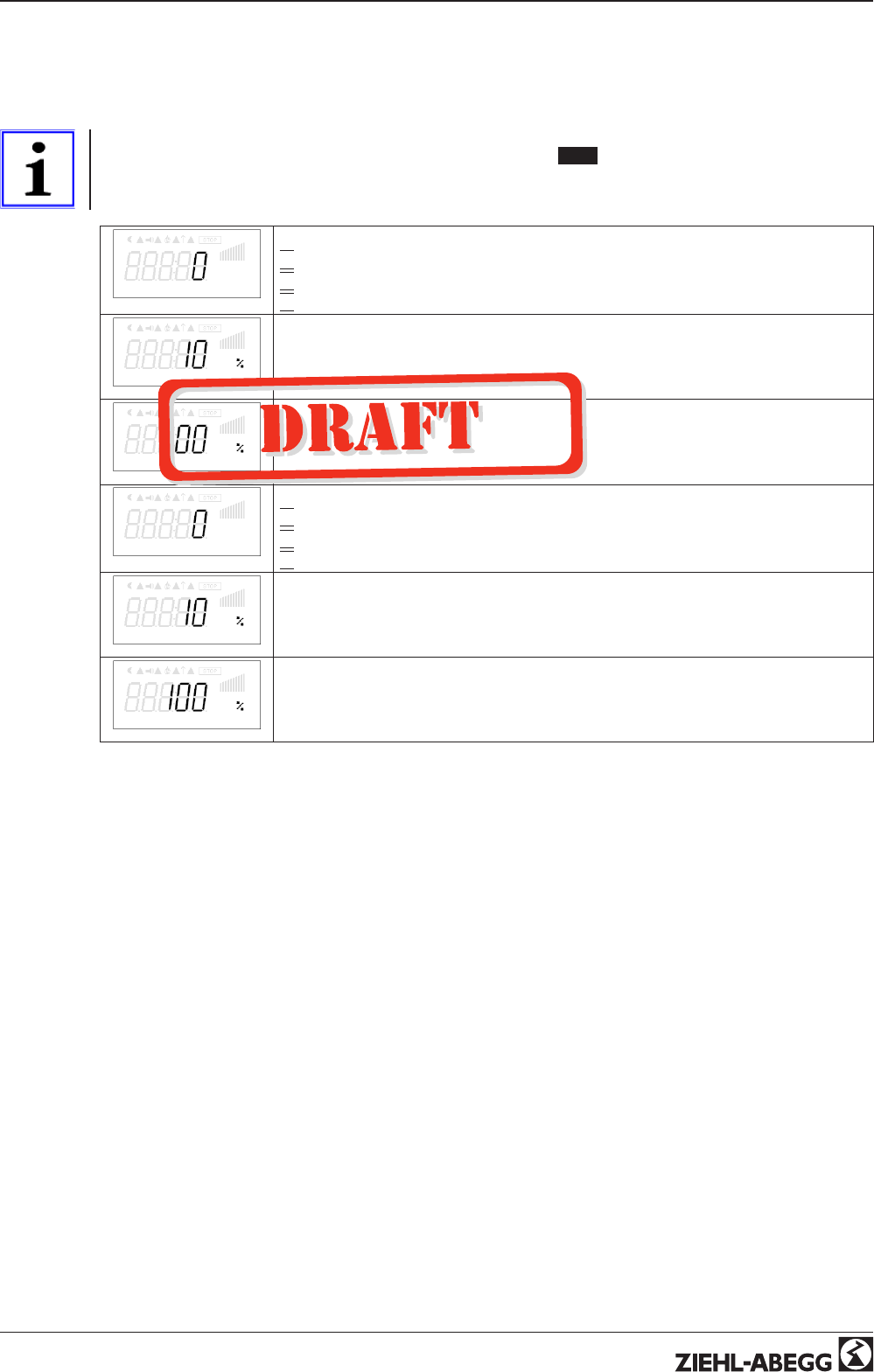
9.10.3 Configuration of analog inputs “E1”and “E3”
9.10.3.1 Signal adaption E2 and E3
If required, an adaptation of the specification signal / speed characteristic curve is possible
Information
These settings are mostly practical for the operating mode 1.01 with rotational speed specification
over an external signal. In operating modes (as of 2.01) this setting is not suited for influencing the
regulation process.
E2 Mode
E2 Mode
|
0
|
= E2 min. / E2 max. without function (factory setting)
|
1
|
= Offset / turn
|
2
|
= signal range
E2 min.
E2 min.
Setting range: 0 - 100 %
Factory setting: 0 %
E2 max.
E2 max.
Setting range: 0 - 100 %
Factory setting: 100 %
E2 Mode
E3 Mode
|
0
|
= E2 min. / E2 max. without function (factory setting)
|
1
|
= Offset / turn
|
2
|
= signal range
E2 min.
E3 min.
Setting range: 0 - 100 %
Factory setting: 0 %
E2 max.
E3 max.
Setting range: 0 - 100 %
Factory setting: 100 %
Operating Instructions AM-PREMIUM / AM-PREMIUM-W – model series Programming
L-BAL-E095-GB 1203 Index 004 Part.-No.
49/68
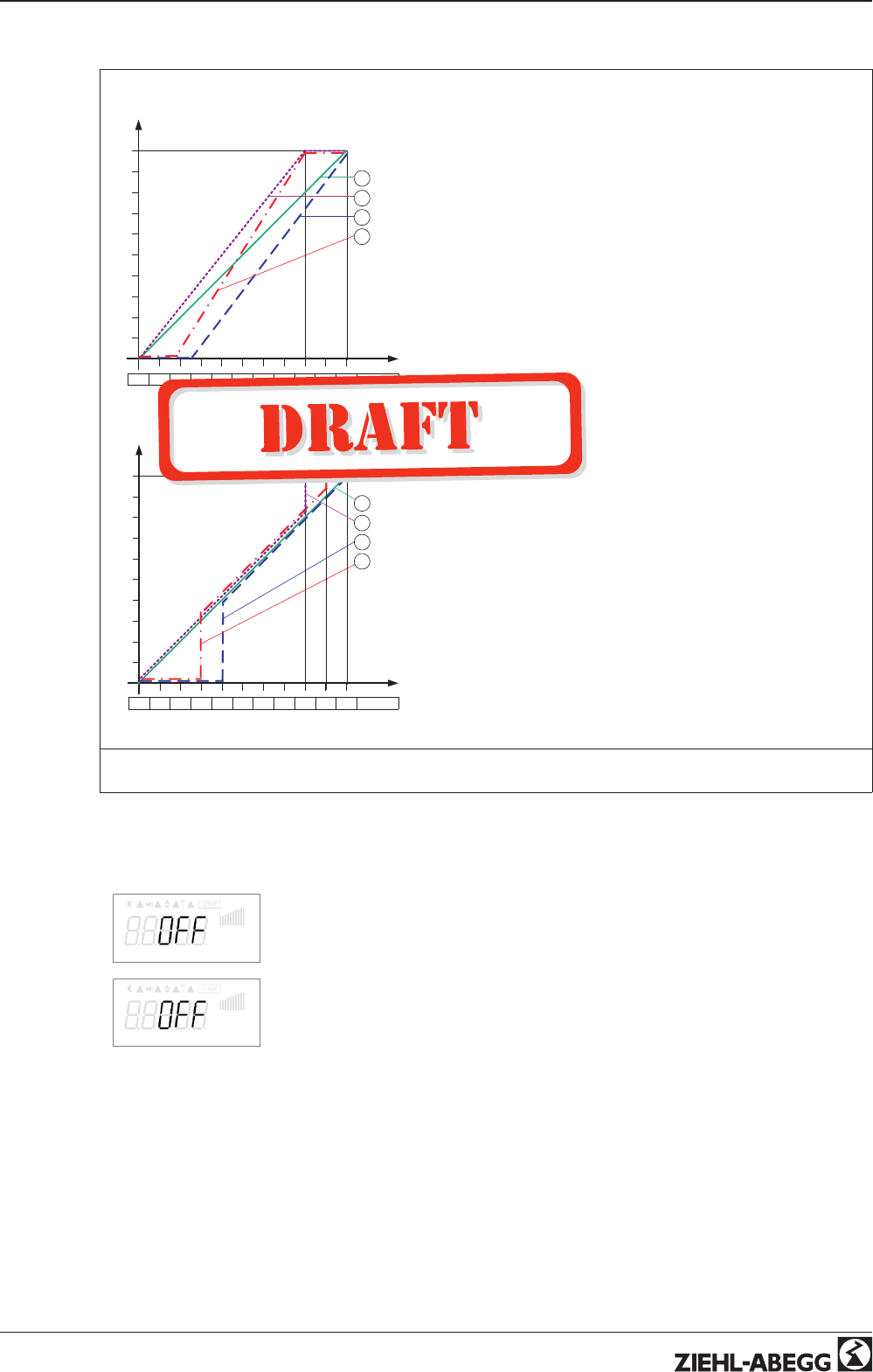
Example for Mode “1.01” with speed setting signal 0 - 10 V
n [%]
Si E
0 1 2 3 4 5 6 7 8 9 10 0 – 10 V 16.11.2009
v_e2_modus_1_prz.vsd
1
Modus 1
E2 min. = 0 %, E2 max. = 100 %
100
2
E2 min. = 25 %, E2 max. = 100 %
80
60
40
20
3
E2 min. = 20 %, E2 max. = 80 %
E2 min. = 0 %, E2 max. = 80 %
4
Modus 1
Example: “E2 min.” = 20 %
The controller begins only at approx. 20% higher
signal with minimal speed.
Example: “E2 max.” = 80 %
Speed rises linear to 100% speed with 80% setting
signal.
Si E
0 1 2 3 4 5 6 7 8 9 10 0 – 10 V
16.11.2009
v_e2_modus_2_prz.vsd
1
Modus 2
E2 min. = 0 %, E2 max. = 100 %
100
2
E2 min. = 40 %, E2 max. = 100 %
80
60
40
20
3
E2 min. = 30 %, E2 max. = 90 %
E2 min. = 0 %, E2 max. = 80 %
4
n [%]
Modus 2
Example: “E2 min.” = 30 %
Only with approx. 30 % setting signal the controller
begins with approx. 30% speed.
Example: “E2 max.” = 80 %
Over 80 % setting signal the speed is switched to
100 %.
n = speed of motor, Si E = setting signal input
Idealized principle diagrams for setting:
“Min. Speed” = 0 % and “Max. Speed” = 100 %
9.10.3.2 Inverting analog inputs “E2” / “E3”
After programming the signal or sensor type, an inversion of the inputs can be carried out.
E2 Inverting
Factory setting for Inverting inputs = “OFF” (if input activated) (signal: 0 - 10 V, 0 - 20
mA, 4 - 20 mA).
For activation using inverted default signals or sensors with inverted output signals
proportional to the measurement range, switch inverting to “ON” (Signal: 10 - 0 V, 20 - 0
mA, 20 - 4 mA).
E3 Inverting
Operating Instructions AM-PREMIUM / AM-PREMIUM-W – model series Programming
L-BAL-E095-GB 1203 Index 004 Part.-No.
50/68
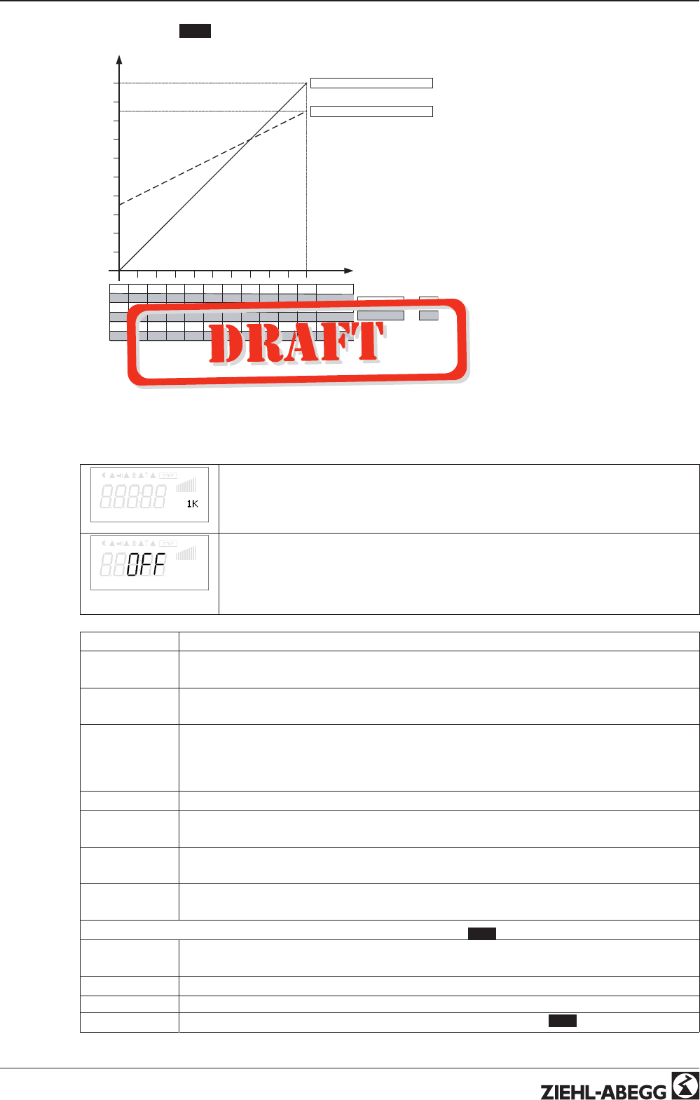
Example: mode 1.01 speed controller, setting by external signal
n Motor
50 %
100 %
Signal
0 1 2 3 4 5 6 7 8 9 10
10 9 8 7 6 5 4 3 2 1 0
0 2 4 6 8 10 12 14 16 18 20
20 18 16 14 12 10 8 6 4 2 0
4 5,6 7,2 8,8 10,4 12 13,6 15,2 16,8 18,4 20
20 18,4 16,8 15,2 13,6 12 10,4 8,8 7,2 5,6 4
0 – 10 V
10 – 0 V
0 – 20 mA
20 – 0 mA
4 – 20 mA
20 – 4 mA
Min.
Min. 0 % Max. = 100 %
Min. 35 % Max. = 85 %
Invertierung ON
Invertierung OFF
15.03.2007
v_invertierung_anlaog_eingaenge.vsd
nM Motor speed
Si Signal
OFF Inverting = OFF
ON Inverting = ON
9.10.4 Function and inverting for relay outputs “K1”
K1 Function
Various functions can be allocated to the relay outputs “K1”.
This is preset at the factory for fault indication.
K1 Inverting
The relay inversion “K1” is set at the factory to “OFF” (when a function is program-
ming).
Switch to “ON” for inversion (switch-time response depends on the allocated function).
Fundamentally, the relay can only become operative if the electronic’s voltage supply is
functioning. At least 2 current phases must be present!
Function Description
OFF No function
Relays remain always de-energized
1K Operating indication.
Operation without fault, reports enable “OFF”
2K Fault indication (factory setting for “K1”, non inverting).
Energized for operation without fault, for enable “OFF” not energized. De-energized at line,
motor and controller fault, Sensor fault dependent on programming, external fault at digital
input.
3K External fault separate with message at digital input (factory setting if terminals bridged)
4K Limit modulation
Over or falling below limits for modulation
5K Limit “E2”
When over or falling below limits for input signal “E2”
6K Limit “E3”
When over or falling below limits for input signal “E3”
For modes as controller higher 2.01
7K Setpoint Offset
Deviation between actual value and setpoint to high
8K Switching on second group
For modes as temperature controller with additional functions 2.03
Operating Instructions AM-PREMIUM / AM-PREMIUM-W – model series Programming
L-BAL-E095-GB 1203 Index 004 Part.-No.
51/68
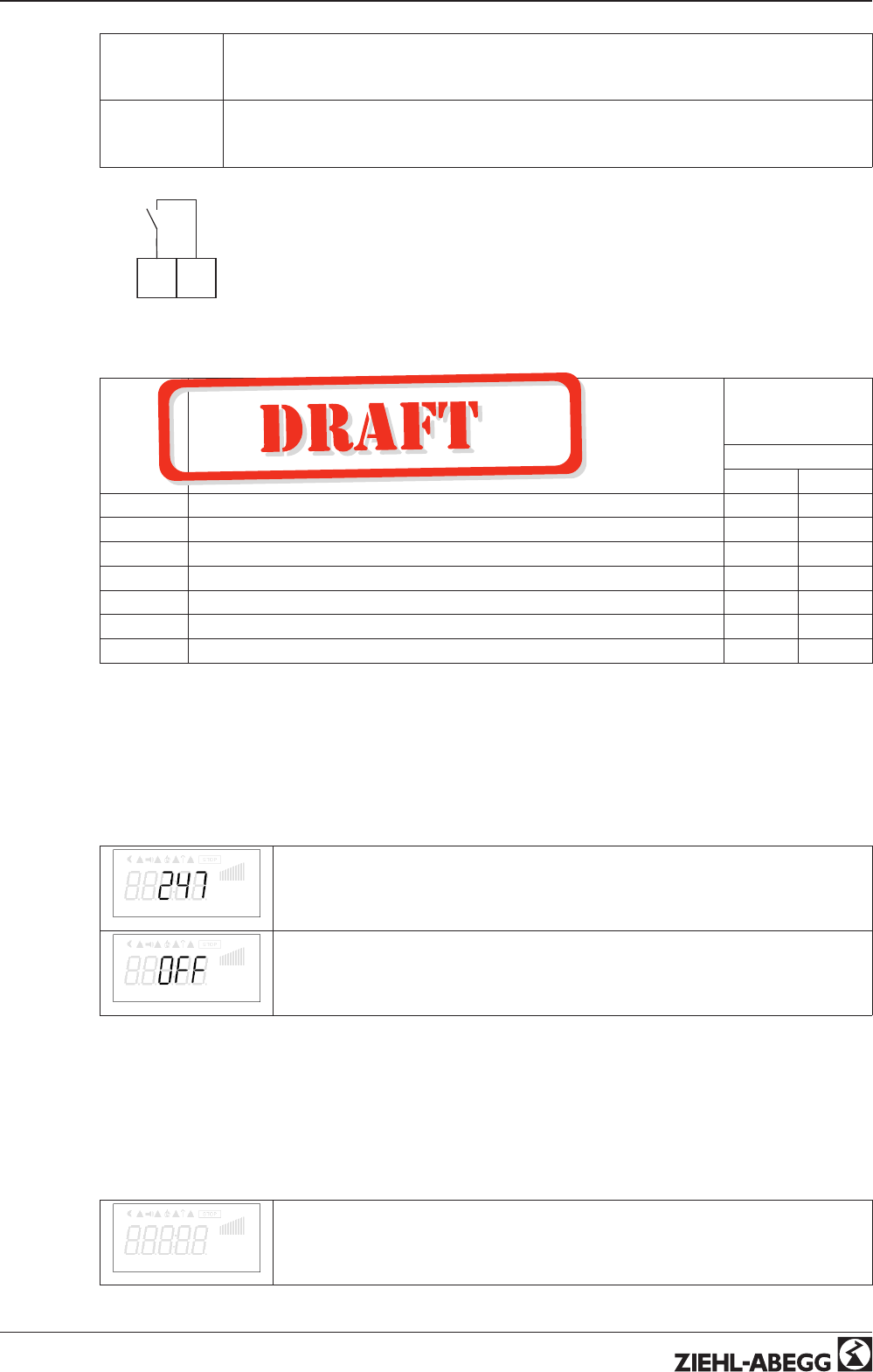
9K Heating function
Switch ON point: temperature = Setpoint +/- Offset
Switch OFF point: Temperature around hysteresis over switch ON point
10K Cooling function
Switch ON point: temperature = Setpoint +/- Offset
Switch OFF point: Temperature around hysteresis below switch ON point
17.09.2009
v_relais_k1_11_14.vsd
K1
1411
K1
1 = energized, terminals 11 - 14 bridged
0 = de-energized 11 - 14 not bridged
Function Status Controller K1
1 = energized
0 = de-energized
Inverting
OFF ON
1K Operation without fault, line supply okay 10
2K Fault with indication by relay 01
3K Ext. Fault at digital input for external fault 10
4K Over or falling below limits for modulation 10
5K over or falling below limits for input signal “E2”10
6K over or falling below limits for input signal “E3”10
7K setpoint deviation to high 10
9.10.5 Networking via MODBUS
It is possible to network several devices with each other. The device uses the MODBUS-RTU as the
protocol for the RS-485 interface.
The device address (Device-ID) is factory set to the highest available MODBUS address: 247
This address is reserved for operation with an external terminal model AXG.. and should not be
occupied with anything else.
Bus Address
Bus Address
The addresses of the individual units must be continuously numbered beginning with
“1”. No address may be allocated twice. MODBUS address adjustable from 1-247.
Address 247 = preprogrammed for an external terminal.
Addressing
Addressing
Switch addressing to “ON” before setting “address”.
Reading and writing parameters
The device supports reading and writing processes for MODBUS Holding Registers. The start address
is 0; the number of registers depends on the device. If the allowable start address or number is
exceeded, the device answers with an exception code. The description of the register is device
dependent and can be requested from service for the device/version concerned.
9.11 Limits
Limits
Menu group Limits
Operating Instructions AM-PREMIUM / AM-PREMIUM-W – model series Programming
L-BAL-E095-GB 1203 Index 004 Part.-No.
52/68
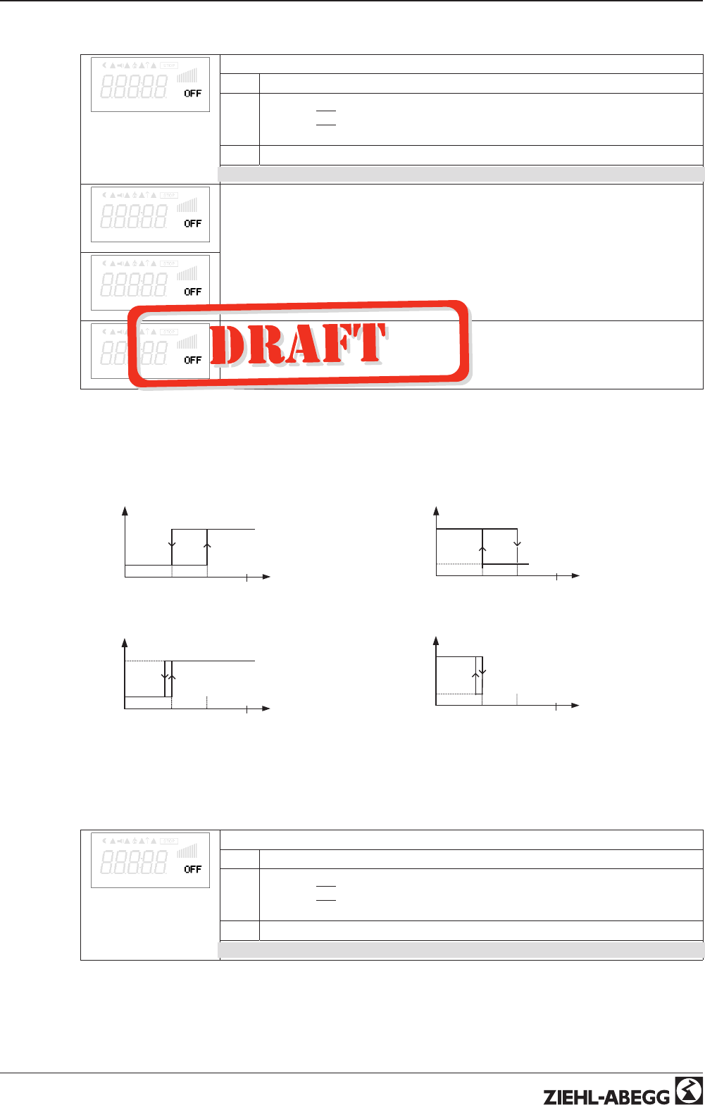
9.11.1 Limit indication depending on modulation
Level. Function
Following functions can be allocated to the limit indication
OFF without function
1L Indication with the centralized fault of a programmed relay (IO allocation
Function
|
2K
|
).
Warning symbol in display, “AL” code in events memory.
2L Is merely displayed in the events menu as message “msg”.
In the IO setup, a separate relay can be allocated independent of these settings.
Level min.
If the modulation exceeds the set “Level max” value, this is reported until the set value
“Level min” has been undercut.
The indication is delayed by the time set in “Display delay”.
Level max.
Level Delay
Time delay exceeding “Level max.” up to indication by relay and alarm symbol.
Setting range: 0 - 120 sec.
Factory setting: 2 sec.
Example indication by relay “K1”:
not inverted
IO Setup: K1 Function = 4K
IO Setup: K1 Inverting = OFF
Inverting
IO Setup: K1 Function = 4K
IO Setup: K1 Inverting = OFF
min max 100 % A
0
1
minmax 100 %
0
1
11.05.2007
v_grenzwert_ausst_k1_ni.vsd
A
A Modulation
min max 100 %
0
1
minmax 100 %
0
1
11.05.2007
v_grenzwert_ausst_k1_i.vsd
A
A
A Modulation
If “Level min.” is higher than “Level max.”, the “Level max.” switching point is without hysteresi.
9.11.2 Limit indication depending on setting or sensor signal
Lmt E2 Function
Following functions can be allocated to the limit indication
OFF without function
1L Indication with the centralized fault of a programmed relay (IO allocation
Function
|
2K
|
).
Warning symbol in display, “AL” code in events memory.
2L Is merely displayed in the events menu as message “msg”.
In the IO setup, a separate relay can be allocated independent of these settings.
Operating Instructions AM-PREMIUM / AM-PREMIUM-W – model series Programming
L-BAL-E095-GB 1203 Index 004 Part.-No.
53/68
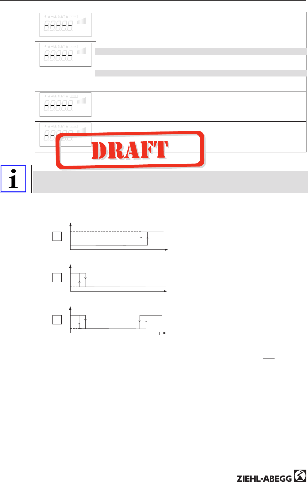
Lmt E2 min.
Both values for E2 (“E2 min” and “E2 max”) can be set independent of each other and
act on a relay together if correspondingly programmed. If a function is activated or if a
relay is allocated, both settings (“min” and “max”) are initially at “OFF”.
Work can be carried out with one as well as with both limit indicators.
The same setting applies to “E3 Min.” and “E3 Max.”, described below for “E2”.
Undercutting the signal (“E2 min”).
If the signal undercuts the set value “E2 min”, this is reported until the set value (plus
adjustable hysteresis) has been exceeded once again.
Exceeding the signal (“E2 max”).
If the signal exceeds the set value “E2 max”, this is reported until the set value (minus
hysteresis) has been undercut once again.
Lmt E2 max
Lmt E2 Hyst.
E2 Hysteresis
Hysteresis adjustment in the unit of measure of the programmed input signal.
Lmt E2 Del.
E2 Delay
Time delay exceeding “Level max.” up to indication by relay and alarm symbol.
Setting range: 0 - 120 sec.
Factory setting: 2 sec.
Information
Always adjust the value for the maximum input signal higher than the value for the minimum input
signal!
E2 Max. > E2 Min.
Example for a limit indication of default signal or sensor signal to “Analog In 1”
50 %
Analog IN
0
1
100 %
1
11.05.2007
v_grenzwert_signal_k1_1.vsd
Settings:
- E2 Max.: 80 %
- E2 Min.: OFF
- switching hysteresis 5 % (from
100 %)
50 %
Analog IN
0
1
100 %
2
11.05.2007
v_grenzwert_signal_k1_2.vsd
Settings:
- E2 Min.: 20 %
- E2 Max.: OFF
- switching hysteresis 5 % (from
100 %)
50 %
Analog IN
0
1
100 %
3
11.05.2007
v_grenzwert_signal_k1_3.vsd
Settings:
- E2 Min.: 20 %
- E2 Max.: 80 %
- switching hysteresis 5 % (from
100 %)
Terminal “E2” and “GND” alarm via relay “K1” (non-inverted) IO Setup → K1 function:
|
5 K
|
= limit
indicators
Operating Instructions AM-PREMIUM / AM-PREMIUM-W – model series Programming
L-BAL-E095-GB 1203 Index 004 Part.-No.
54/68
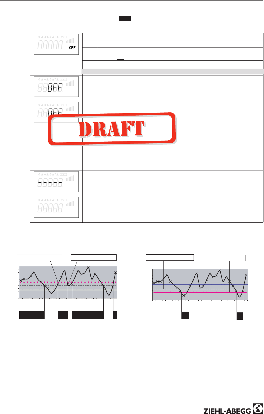
9.11.3 Limit indication depending on (offset) to Setpoint
In operating modes as a controller (via 2.01 ), two limit indicators can be carried out based on the set
target value (Setpoint) and measured actual value (on E2).
Offset Function
Following functions can be allocated to the limit indication
OFF without function
1L Indication with the centralized fault of a programmed relay (IO allocation
function
|
2K
|
) warning symbol in display, “AL” code in events memory.
2L Is merely displayed in the events menu as message “msg”.
In the IO setup, a separate relay can be allocated independent of these settings.
Offset 1
Offset 1, Offset 2
Both values for Offset 1 and Offset 2 can be set independent of each other and act on
a relay together if correspondingly programmed. If a function is activated or if a relay is
allocated both settings (Offset 1 and Offset 2) are initially at “OFF”.
Work can be carried out with one as well as with both limit indicators.
“Offset 1” for alarm in case of an exceeding of the max. deviation between actual and
target.
Switch ON point: actual value = Setpoint +/- offset
Swtich OFF point: Actual value by hysteresis under the switch-on point
“Offset 2” for alarm in case of an undercutting of the max. deviation between actual and
target
Switch ON point: actual value = Setpoint +/- offset
Swtich OFF point: Actual value by hysteresis over the switch-on point
Offset 2
Offset Hyst.
Offset Hysteresis
Hysteresis switch-on point: In temperature regulation + / - 10 K, otherwise sensors 10
% of measurement range
Offset Del.
Offset Delay
Time delay until indication through relay and alarm symbol.
Setting range: 0 - 120 sec.
Factory setting: 2 sec.
Example for temperature regulation; for other modes of operation settings in corresponding sensor
unit.
Offset 1 for alarm during exceeding
10
12
14
16
18
20
22
24
26
28
30
1 3 5 7 9 11 13 15 17 19 21 23 25 27 29
[min]
[°C]
ON ON ON
ON = 15°C + 5 K = 20 °C OFF = 20°C - 2 K = 18 °C
16.03.2007
v_relais_kuehlen_10k_pos_offset.vsd
Example: Setpoint 15.0 °C, Offset +5.0 K, Hysteresis 2.0 K
Offset 2 for alarm during undercutting
10
12
14
16
18
20
22
24
26
28
30
1 3 5 7 9 11 13 15 17 19 21 23 25 27 29
[min]
[°C]
ON
OFF = 15°C + 2 K = 17 °C ON = 20°C - 5K = 15 °C
ON
16.03.2007
v_relais_heizen_9k_neg_offset.vsd
Example: Setpoint 15.0° C, Offset -5.0 K, Hysteresis 2.0 K
Operating Instructions AM-PREMIUM / AM-PREMIUM-W – model series Programming
L-BAL-E095-GB 1203 Index 004 Part.-No.
55/68
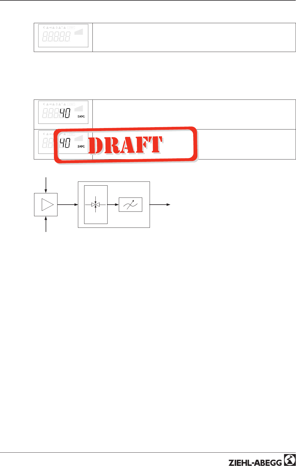
9.12 Motor Setup
Motor Setup
Menu group Motorsetup
9.12.1 Setting for Rampup time and Rampdown time
By separate menus for Rampup time and Rampdown time an adjustment is possible to individual
system conditions.
This function is switched behind the actual controller function.
Rampup time
Rampup time
Time setting in which the automatic controller output from 0 % to 100 % rises.
Setting range: 2...250 sec.
Factory setting depending on motor
Rampdown time
Rampdown time
Time setting in which the automatic controller output from 100 % to 0 % reduces.
Setting range: 2...250 sec.
Factory setting depending on motor
0 .. 100 %
3
4
1
209.05.2007
v_hochlaufzeit_ruecklaufzeit.vsd
1 external Signal
2 Setting
3 Rampup time
4 Rampdown time
Operating Instructions AM-PREMIUM / AM-PREMIUM-W – model series Programming
L-BAL-E095-GB 1203 Index 004 Part.-No.
56/68
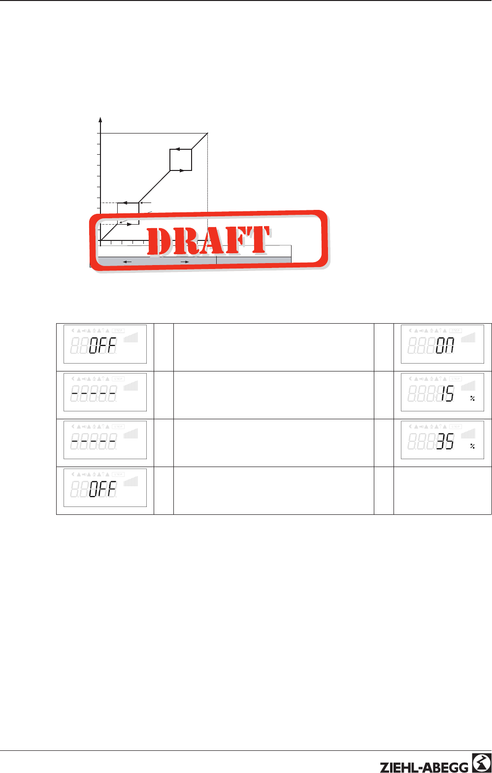
9.12.2 Suppression of speeds
Suppression of up to three speed ranges.
Under certain circumstances, it is possible to prevent disturbing noises that can arise at certain
speeds due to resonances.
Example for suppression of 2 ranges (Idealized principle diagram)
A
D
P
50 %
50 %
R
0 %
I
S
100 %
I
35 % max
15 % min
09.05.2007
v_ausblendung_prz.vsd
100 %
1
2
A Modulation
S Setpoint
R Pband
D Speed controller: setting signal
P P-controller: control deviation
Setting depending on device type in: %, Hz,
rpm
Suppression1
→Factory setting no suppression active = “OFF”→
Suppression1
Range1 min.
→Setting for “Range1 min.”→
Range1 min.
Range1 max.
→Setting for “Range1 max.”→
Range1 max.
Suppression2
→Identical procedures for Suppression2 and Sup-
pression3, as far as desired
→etc.
Operating Instructions AM-PREMIUM / AM-PREMIUM-W – model series Programming
L-BAL-E095-GB 1203 Index 004 Part.-No.
57/68
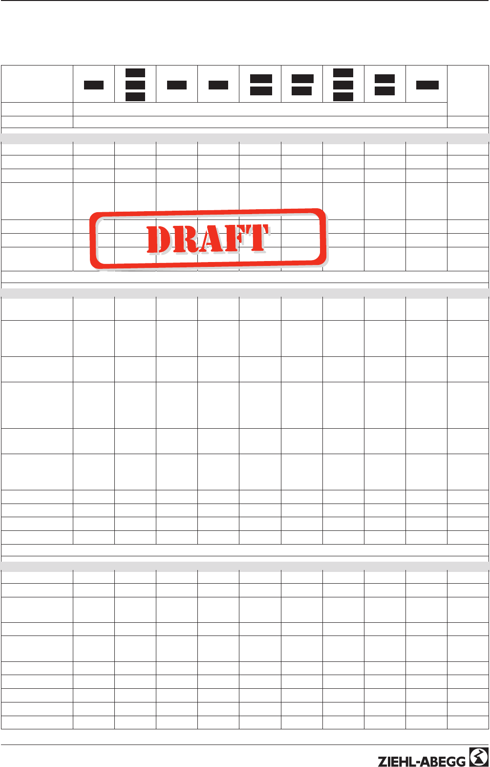
10 Menu tables
10.1 Menues of operating modes
Mode
1.01
2.01
2.03
2.04
2.02 2.05 3.01
3.02
3.03
3.04
4.01
4.02
4.03
5.01
5.02 6.01
User Set-
ting
Parameter Factory setting
Start
PIN input - - - - - - - - - - - - - - - - - - - - - - - - - - - - - - - - - - - - - - - - - - - - -
Language GB GB GB GB GB GB GB GB GB
Reset OFF OFF OFF OFF OFF OFF OFF OFF OFF
Mode 1.01
2.01
2.03
2.04
2.02 2.05 3.01
3.02
3.03
3.04
4.01
4.02
4.03
5.01
5.02 6.01
ECblue Premium 4.00 4.00 4.00 4.00 4.00 4.00 4.00 4.00 4.00
Basic Version 10.01 10.01 10.01 10.01 10.01 10.01 10.01 10.01 10.01
SN: 1727393-
6FF33
1727393-
6FF33
1727393-
6FF33
1727393-
6FF33
1727393-
6FF33
1727393-
6FF33
1727393-
6FF33
1727393-
6FF33
1727393-
6FF33
Info
Actual value E2-
E3 -2.4 °C
Control value
(only 2.04, 3.03,
3.04)
30.0 °C 12.0 bar
22.6 °C
E2 Actual 30.0 °C 30.0 °C 30.0 °C 10.0 bar
9.5 °C
10.0 bar
9.5 °C88.7 Pa 712 m
3
h 0.45 m/s
E3 Actual
(only 2.04, 2.05,
3.03, 3.04, 4.02,
4.03, 5.02)
30.0 °C 30.0 °C 10.0 bar
9.5 °C21.0 °C 21.0 °C
Setpoint1 20.0 °C 5.0 °C 0.0 °C 12.0 bar
35.0°C
12.0 bar
35.0°C100 Pa 530 m
3
h 0.50 m/s
Setpoint control
(only 4.02, 4.03,
5.02)
100 Pa 530 m
3
h
Speed 0 rpm 0 rpm 0 rpm 0 rpm 0 rpm 0 rpm 0 rpm 0 rpm 0 rpm
Motor current 0.0 A 0.0 A 0.0 A 0.0 A 0.0 A 0.0 A 0.0 A 0.0 A 0.0 A
Set external1 0 rpm
Msco OFF OFF OFF OFF OFF OFF OFF OFF
Setting
Set Intern1 200 rpm
Set Intern2 - - - - --
Setpoint1 20.0 °C 5.0 °C 0.0 °C 12.0 bar
35.0°C
12.0 bar
35.0°C100 Pa 530 m
3
h 0.50 m/s
Setpoint2 - - - - - - - - - - - - - - - - - - - - - - - - - - - - - - - - - - - - - - - -
Pband 5.0 K 20.0 K 5.0 K 5.0 bar
7.0 °C
5.0 bar
7.0 °C100 Pa 530 m
3
h 0.50 m/s
Min. Speed *0 rpm 0 rpm 0 rpm 0 rpm 0 % 0 % 0 rpm 0 rpm 0 rpm
Max. Speed *1800 rpm 1800 rpm 1800 rpm 1800 rpm 1800 rpm 1800 rpm 1800 rpm 1800 rpm 1800 rpm
Set external1 ON
Manual mode OFF OFF OFF OFF OFF OFF OFF OFF
Speed man. 200 rpm 200 rpm 200 rpm 200 rpm 200 rpm 200 rpm 200 rpm 200 rpm
Operating Instructions AM-PREMIUM / AM-PREMIUM-W – model series Menu tables
L-BAL-E095-GB 1203 Index 004 Part.-No.
58/68
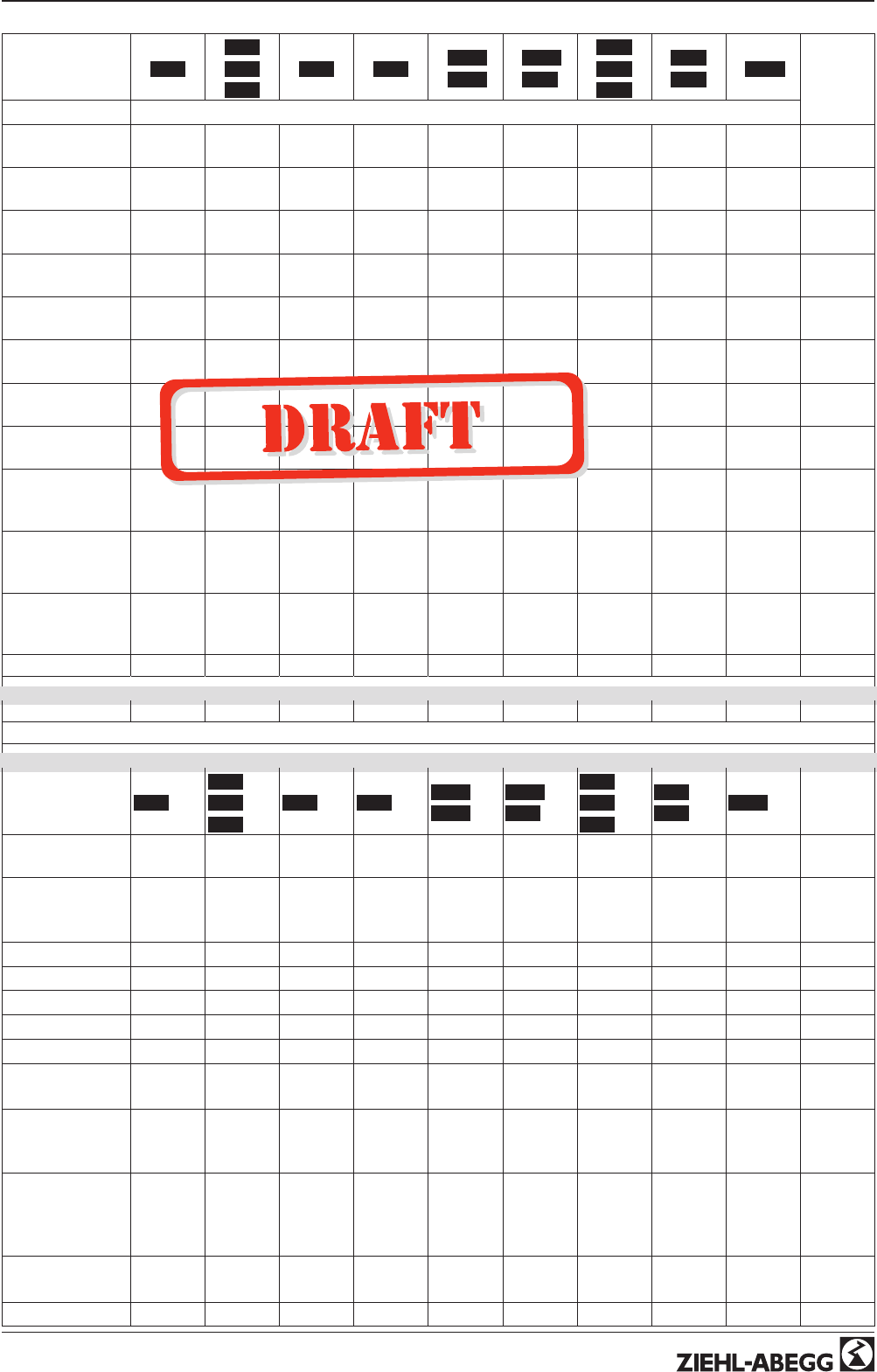
Mode
1.01
2.01
2.03
2.04
2.02 2.05 3.01
3.02
3.03
3.04
4.01
4.02
4.03
5.01
5.02 6.01
User Set-
ting
Parameter Factory setting
Offset AnalogOut 2.03 =
0.0 K
Pband AnalogOut 2.03 =
2.0 K
Min. AnalogOut 2.03 =
0 %
Max. AnalogOut 2.03 =
100 %
OffsetDigitalOut 2.03 =
-1.0 K
Hyst.DigitalOut 2.03 =
1.0 K
Alarm Minimum 2.03 =
0.0 °C
Alarm Maximum 2.03 =
40.0 °C
T-Band SA 4.02 +
4.03 =
30.0 K
5.02 =
30.0 K
T-Start SA 4.02 +
4.03 =
15.0 °C
5.02 =
15.0 °C
P-Min SA 4.02 +
4.03 =
70.0 Pa
5.02 =
70.0 m
3
h
Events
Base setup
Mode 1.01
2.01
2.03
2.04
2.02 2.05 3.01
3.02
3.03
3.04
4.01
4.02
4.03
5.01
5.02 6.01
E2 Analog In 0 - 10 V KTY KTY KTY 0-30
MBG
0-30
MBG DSG200 DSG200 0-1 MAL
E2 Refrigerant
(only 3.02 and
3.04)
R503 R503
E2 K-Factor 75
E2 Min. - - - - - - - - - - - - - - - - - - - - - - - - - - - - - - - - - - - - - - - -
E2 Max. - - - - - - - - - - - - - - - - - - - - - - - - - - - - - - - - - - - - - - - -
E2 Decimals - - - - - - - - - - - - - - - - - - - - - - - - - - - - - - - - - - - - - - - -
E2 Unit - - - - - - - - - - - - - - - - - - - - - - - - - - - - - - - - - - - - - - - -
E2 Offset 0.0 K 0.0 K 0.0 K 0.0 bar
0.0 K
0.0 bar
0.0 K 0.0 Pa 0.0 Pa 0.0 m/s
E3 Function OFF
OFF
2.04 =
4E
OFF 5E OFF 4E 4.02 +
4.03 = 6E
5.02 =
6E OFF
E3 Analog In - - - - - - - - - - - - - - - 0-30
MBG
4.02 =
TF
4.03 =
Bus
5.02 =
TF OFF
E3 Refrigerant
(only 3.04) - - - - - R503
E3 K-Factor 75
Operating Instructions AM-PREMIUM / AM-PREMIUM-W – model series Menu tables
L-BAL-E095-GB 1203 Index 004 Part.-No.
59/68
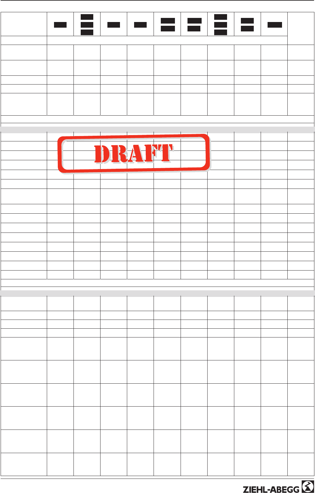
Mode
1.01
2.01
2.03
2.04
2.02 2.05 3.01
3.02
3.03
3.04
4.01
4.02
4.03
5.01
5.02 6.01
User Set-
ting
Parameter Factory setting
E3 Min. - - - - - - - - - - - - - - - 4.03 = -
35.0 °C- - - - - - - - - -
E3 Max. - - - - - - - - - - - - - - - 4.03 =
65.0 °C- - - - - - - - - -
E3 Decimals - - - - - - - - - - - - - - - - - - - - - - - - - - - - - -
E3 Unit - - - - - - - - - - - - - - - 4.03 = °C - - - - - - - - - -
E3 Offset - - - - - - - - - - 0.0 bar
0.0 K
4.02 +
4.03 =
0.0 K
5.02 =
0.0 K - - - - -
Controller Setup
PIN Protection OFF OFF OFF OFF OFF OFF OFF OFF OFF
Set protection OFF OFF OFF OFF OFF OFF OFF OFF OFF
Save User Setup OFF OFF OFF OFF OFF OFF OFF OFF OFF
Alarm sensors OFF OFF OFF OFF OFF OFF OFF OFF
Limit - - - - - - - - - - - - - - - - - - - - - - - - - - - - - - - - - - - - - - - - - - - - -
Min. speed cut off OFF OFF OFF OFF OFF OFF OFF OFF
Group 2 ON
value - - - - - - - - - - - - - - - - - - - - - - - - - - - - - - - - - - - - - - - - - - - - -
nmin at Group2 - - - - - - - - - - - - - - - - - - - - - - - - - - - - - - - - - - - - - - - - - - - - -
Val > Set=n+ ON ON ON ON ON OFF OFF OFF
Type of control P P P P P Pid Pid Pid
KP 50 % 50 % 50 % 50 % 50 % 50 % 50 % 50 %
KI 50 % 50 % 50 % 50 % 50 % 50 % 50 % 50 %
KD 50 % 50 % 50 % 50 % 50 % 50 % 50 % 50 %
TI 0 % 0 % 0 % 0 % 0 % 0 % 0 % 0 %
LED Mode ON ON ON ON ON ON ON ON ON
IO Setup
A Function 1A 1A (2.03
= 6A) 1A 1A 1A 1A 1A 1A 1A
A min. 0.0 V 0.0 V 0.0 V 0.0 V 0.0 V 0.0 V 0.0 V 0.0 V 0.0 V
A max. 10.0 V 10.0 V 10.0 V 10.0 V 10.0 V 10.0 V 10.0 V 10.0 V 10.0 V
A Inverting OFF OFF OFF OFF OFF OFF OFF OFF OFF
D1 Function OFF OFF OFF OFF OFF OFF
OFF
4.03 =
1D
OFF OFF
D1 Inverting - - - - - - - - - - - - - - - - - - - - - - - - - - - - - -
- - - - -
4.03 =
OFF
- - - - - - - - - -
D1 Busmode - - - - - - - - - - - - - - - - - - - - - - - - - - - - - -
- - - - -
4.03 =
ON
- - - - - - - - - -
D2 Function OFF OFF OFF OFF OFF OFF
OFF
4.03 =
5D
OFF OFF
D2 Inverting - - - - - - - - - - - - - - - - - - - - - - - - - - - - - -
- - - - -
4.03 =
OFF
- - - - - - - - - -
D2 Busmode - - - - - - - - - - - - - - - - - - - - - - - - - - - - - -
- - - - -
4.03 =
ON
- - - - - - - - - -
Operating Instructions AM-PREMIUM / AM-PREMIUM-W – model series Menu tables
L-BAL-E095-GB 1203 Index 004 Part.-No.
60/68
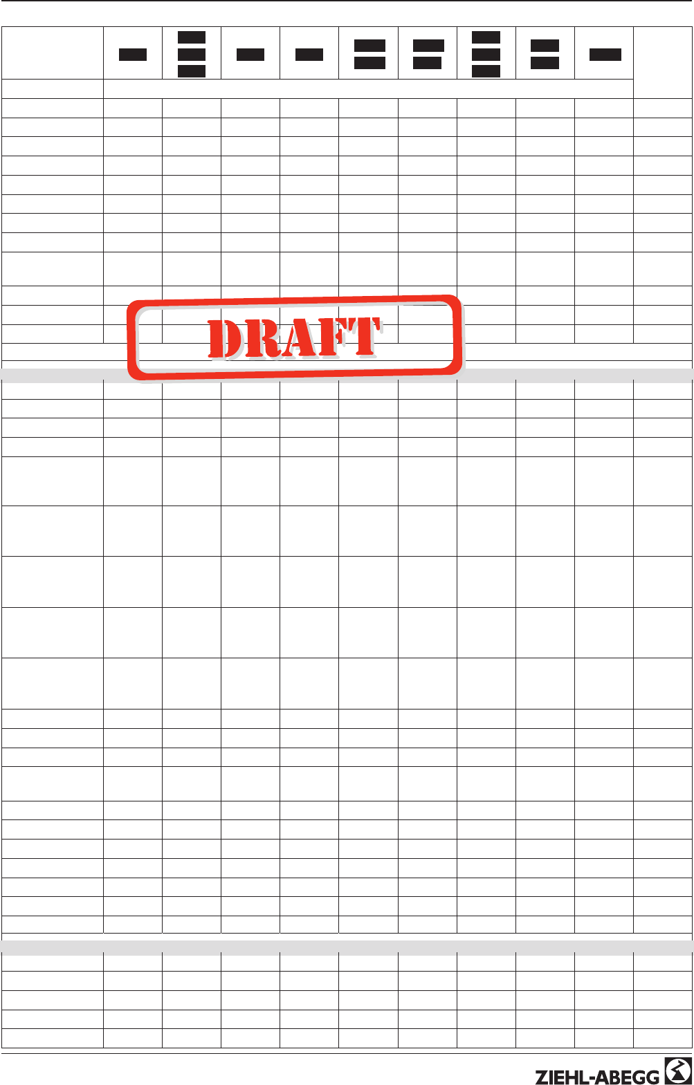
Mode
1.01
2.01
2.03
2.04
2.02 2.05 3.01
3.02
3.03
3.04
4.01
4.02
4.03
5.01
5.02 6.01
User Set-
ting
Parameter Factory setting
E2 Mode 0 0 0 0 0 0 0 0 0
E2 min. 0 % 0 % 0 % 0 % 0 % 0 % 0 % 0 % 0 %
E2 max. 100 % 100 % 100 % 100 % 100 % 100 % 100 % 100 % 100 %
E2 Inverting OFF OFF OFF OFF OFF OFF OFF OFF OFF
E3 Mode 0 0 0 0 0 0 0 0 0
E3 min. 0 % 0 % 0 % 0 % 0 % 0 % 0 % 0 % 0 %
E3 max. 100 % 100 % 100 % 100 % 100 % 100 % 100 % 100 % 100 %
E3 Inverting - - - - - - - - - - - - - - - - - - - - - - - - - - - - - - - - - - - - - - - - - - - - -
K1 Function 1K 1K (2.03
= 2K) 1K 1K 1K 1K 1K 1K 1K
K1 Inverting OFF OFF OFF OFF OFF OFF OFF OFF OFF
Bus Address 247 247 247 247 247 247 247 247 247
Addressing OFF OFF OFF OFF OFF OFF OFF OFF OFF
Limits
Level Function OFF OFF OFF OFF OFF OFF OFF OFF OFF
Level min. - - - - - - - - - - - - - - - - - - - - - - - - - - - - - - - - - - - - - - - - - - - - -
Level max. - - - - - - - - - - - - - - - - - - - - - - - - - - - - - - - - - - - - - - - - - - - - -
Level Delay - - - - - - - - - - - - - - - - - - - - - - - - - - - - - - - - - - - - - - - - - - - - -
Lmt E2 Function OFF
OFF
(2.03 =
1L)
OFF OFF OFF OFF OFF OFF OFF
Lmt E2 min. - - - - -
- - - - -
2.03 =
0.0 °C
- - - - - - - - - - - - - - - - - - - - - - - - - - - - - - - - - - -
Lmt E2 max. - - - - -
- - - - -
2.03 =
40.0 °C
- - - - - - - - - - - - - - - - - - - - - - - - - - - - - - - - - - - -
Lmt E2 Hyst. - - - - -
- - - - -
2.03 =
1.0 K
- - - - - - - - - - - - - - - - - - - - - - - - - - - - - - - - - - -
Lmt E2 Del. - - - - -
- - - - -
2.03 = 2
sec.
- - - - - - - - - - - - - - - - - - - - - - - - - - - - - - - - - - -
Lmt E3 Function - - - - - - - - - - - - - - - - - - - - - - - - - - - - - - - - - - - - - - - - - - - - -
Lmt E3 min. - - - - - - - - - - - - - - - - - - - - - - - - - - - - - - - - - - - - - - - - - - - - -
Lmt E3 max. - - - - - - - - - - - - - - - - - - - - - - - - - - - - - - - - - - - - - - - - - - - - -
GW E3 Hystere-
sis - - - - - - - - - - - - - - - - - - - - - - - - - - - - - - - - - - - - - - - - - - - - -
Lmt E3 Del. - - - - - - - - - - - - - - - - - - - - - - - - - - - - - - - - - - - - - - - - - - - - -
Offset Function OFF OFF OFF OFF OFF OFF OFF OFF
Offset 1 - - - - - - - - - - - - - - - - - - - - - - - - - - - - - - - - - - - - - - - -
Offset 2 - - - - - - - - - - - - - - - - - - - - - - - - - - - - - - - - - - - - - - - -
Offset Hyst. - - - - - - - - - - - - - - - - - - - - - - - - - - - - - - - - - - - - - - - -
Offset Del. - - - - - - - - - - - - - - - - - - - - - - - - - - - - - - - - - - - - - - - -
Motor Setup
Rampup time*10 sec 10 sec 10 sec 10 sec 10 sec 10 sec 10 sec 10 sec 10 sec
Rampdown time*2 sec 2 sec 2 sec 2 sec 2 sec 2 sec 2 sec 2 sec 2 sec
Suppression1 *OFF OFF OFF OFF OFF OFF OFF OFF OFF
Range1 min. *- - - - - - - - - - - - - - - - - - - - - - - - - - - - - - - - - - - - - - - - - - - - -
Range1 max. *- - - - - - - - - - - - - - - - - - - - - - - - - - - - - - - - - - - - - - - - - - - - -
Operating Instructions AM-PREMIUM / AM-PREMIUM-W – model series Menu tables
L-BAL-E095-GB 1203 Index 004 Part.-No.
61/68
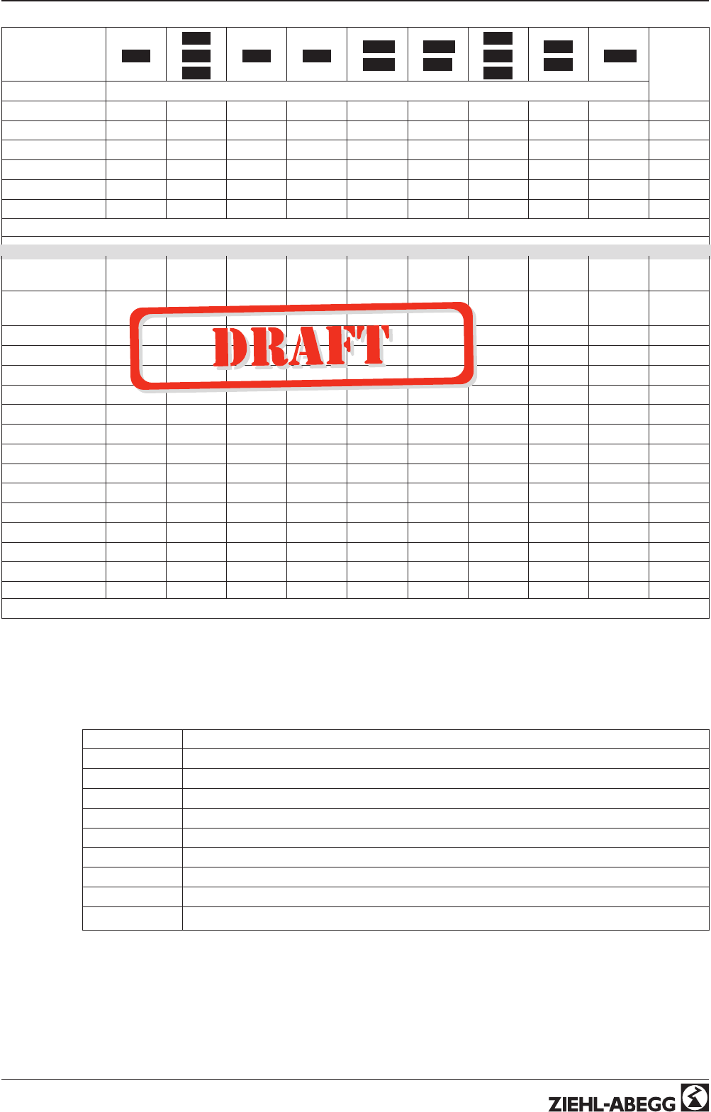
Mode
1.01
2.01
2.03
2.04
2.02 2.05 3.01
3.02
3.03
3.04
4.01
4.02
4.03
5.01
5.02 6.01
User Set-
ting
Parameter Factory setting
Suppression2 *OFF OFF OFF OFF OFF OFF OFF OFF OFF
Range2 min. *- - - - - - - - - - - - - - - - - - - - - - - - - - - - - - - - - - - - - - - - - - - - -
Range2 max. *- - - - - - - - - - - - - - - - - - - - - - - - - - - - - - - - - - - - - - - - - - - - -
Suppression3 *OFF OFF OFF OFF OFF OFF OFF OFF OFF
Range3 min. *- - - - - - - - - - - - - - - - - - - - - - - - - - - - - - - - - - - - - - - - - - - - -
Range3 max. *- - - - - - - - - - - - - - - - - - - - - - - - - - - - - - - - - - - - - - - - - - - - -
Diagnostic
OTC 000056:-
46:13
000056:-
46:13
000056:-
46:13
000056:-
46:13
000056:-
46:13
000056:-
46:13
000056:-
46:13
000056:-
46:13
000056:-
46:13
OTM 000056:-
46:13
000056:-
46:13
000056:-
46:13
000056:-
46:13
000056:-
46:13
000056:-
46:13
000056:-
46:13
000056:-
46:13
000056:-
46:13
DC-Voltage 415 V 415 V 415 V 415 V 415 V 415 V 415 V 415 V 415 V
Line voltage 240 V 240 V 240 V 240 V 240 V 240 V 240 V 240 V 240 V
Heatsink 28.8 °C 28.8 °C 28.8 °C 28.8 °C 28.8 °C 28.8 °C 28.8 °C 28.8 °C 28.8 °C
Capacitor 29.5 29.5 29.5 29.5 29.5 29.5 29.5 29.5 29.5
E2-KTY 20.0 °C 20.0 °C 20.0 °C 20.0 °C 20.0 °C 20.0 °C 20.0 °C 20.0 °C 20.0 °C
E2-Current 9.0 mA 9.0 mA 9.0 mA 9.0 mA 9.0 mA 9.0 mA 9.0 mA 9.0 mA 9.0 mA
E2-Voltage 4.0 V 4.0 V 4.0 V 4.0 V 4.0 V 4.0 V 4.0 V 4.0 V 4.0 V
E3-KTY 20.0 °C 20.0 °C 20.0 °C 20.0 °C 20.0 °C 20.0 °C 20.0 °C 20.0 °C 20.0 °C
E3-Current 9.0 mA 9.0 mA 9.0 mA 9.0 mA 9.0 mA 9.0 mA 9.0 mA 9.0 mA 9.0 mA
E3-Voltage 4.0 V 4.0 V 4.0 V 4.0 V 4.0 V 4.0 V 4.0 V 4.0 V 4.0 V
D1 OFF OFF OFF OFF OFF OFF OFF OFF OFF
D2 OFF OFF OFF OFF OFF OFF OFF OFF OFF
K1 OFF OFF OFF OFF OFF OFF OFF OFF OFF
* Factory setting depending on motor, changed settings are not put back on activation of factory setting!
10.2 Possible allocation of the IOs, PINs
Analog output A
Function Description Function A
OFF without function
1A Constant voltage +10 V
2A proportional level control
3A proportional input E2
4A proportional input E3
5A Group control
6A only 2.03 Cooling function
7A only 2.03 Heating function
9A proportionally to speed
Operating Instructions AM-PREMIUM / AM-PREMIUM-W – model series Menu tables
L-BAL-E095-GB 1203 Index 004 Part.-No.
62/68

Digital inputs D1 + D2
Function Description Function D1 + D2
OFF No function
1D Enable (remote control) “ON” / “OFF”
2D External error
3D “Limit” ON / OFF
4D Switch over “E1” / “E3”
For mode speed controller 1.01
5D Switch over “Setpoint Intern1” / “Setpoint Intern2”
6D Switch over “Intern” / “Extern”
For modes as controller from 2.01
5D Switch over “Setpoint1” / “Setpoint2”
6D Switch over “Intern” / “Extern”
7D Switch over “automatic control” / “Speed manual”
8D Switch over control function (e.g. “heating” / “cooling”)
10D “Reset”
11D Setting Max. Speed “ON” / “OFF”
13D Switch over direction of rotation “right” / “ left”
14D “Freeze function” = maintain momentary modulation value
Analog input E2 / E3 (IO Setup)
Mode Description E2 Modus
0E2 min. / E2 max. without function (factory setting)
1Offset / turn
2Signal range
Analog input E3 (Base setup)
Function Description Function E3
OFF No function
1E external Setpoint
2E external Manual mode (from 2.01 )
3E Sensor average to E2 (from 2.01 )
4E Sensor comparison to E2
5E Sensor difference to E2 (from 2.01 )
6E Sensor for Setpoint (from 2.01 )
7E Measurement value (from 2.01 )
Operating Instructions AM-PREMIUM / AM-PREMIUM-W – model series Menu tables
L-BAL-E095-GB 1203 Index 004 Part.-No.
63/68

Digital output K1
Function Description Function K1 (not inverted)
OFF No function
Relay remains always, i.e. de-energized
1K Operating indication
Operation without fault, reports enable “OFF”
2K Fault indication
Energized for operation without fault, for enable “OFF” not energized. De-energized at line,
motor and controller fault, Sensor fault dependent on programming, external fault at digital
input.
3K External fault separate with message at digital input (factory setting if terminals bridged)
4K Limit modulation
Over or falling below limits for modulation
5K Limit “E2”
When over or falling below limits for input signal “E2”
6K Limit “E3”
When over or falling below limits for input signal “E3”
For modes as controller from 2.01
7K Setpoint Offset
Deviation between actual value and setpoint to high
8K Group control
Switching on fans depending on modulation
For modes as temperature controller with additional functions 2.03
9K Heating function
Switch ON point: temperature = Setpoint +/- Offset
Switch OFF point: Temperature around hysteresis over switch ON point
10K Cooling function
Switch ON point: temperature = Setpoint +/- Offset
Switch OFF point: Temperature around hysteresis below switch ON point
Limits GW E2, GW E3
Function Description Function GW E2, GW E3
OFF without function
1L Indication with the centralized fault of a programmed relay (IO allocation Function
|
2K
|
).
Warning symbol in display, “AL” code in events memory.
2L Is merely displayed in the events menu as message “msg”.
PINs
PIN Function
PIN 0010 Opening service menu, if PIN-protection activated
PIN 1234 Opening “setting”.
if “set protection” = “ON” (
Controller Setup)
PIN 9090 Restore user setting
PIN 9091 Save user setting (corresponds function “Save user setup” = “ON”
Controller Setup)
PIN 9095 Restore factory setting = delivery status
Operating Instructions AM-PREMIUM / AM-PREMIUM-W – model series Menu tables
L-BAL-E095-GB 1203 Index 004 Part.-No.
64/68
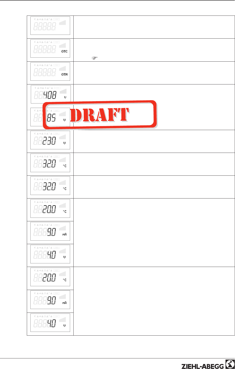
11 Diagnostics menu
Diagnostic
The diagnostics menu supplies information about the momentary operating condition
of the device.
00056:46:13
O = Operation, T = Time, C = Controller
The time counting runs, as soon as mains voltage is connected (without fault).
If events step on (Motor fault, External Error, etc.), the period of operation is stored at
this time (
Events).
00056:46:13
O = Operation, T = Time, M = Motor
The time counting runs as soon as a modulation of the controller is present
DC-Voltage
For 1 ~ types
ZK voltage constant at approx. 400 V
The PFC (Power Factor Controller) makes it mostly independent of the mains voltage.
DC-Voltage
For 3 ~ types
The intermediate circuit voltage without load is the peak value of the input voltage.
In a three-phase supply network with 400 V, an intermediate circuit voltage of ca. 565 V
results. This voltage sinks slightly under load.
Line voltage
Line voltage
Heatsink
Display of DC-Choke or Capacitor temperature. In case of temperature increase above
predetermined threshold value (from 90 °C) the output power will be automatic re-
duced.
Capacitor
Display of DCLink Elco temperature. During impermissibly high levels (from 75 °C on),
the output power is automatically reduced.
At 90 °C switch off.
E2-KTY
Signal height at analog input E2 (Analog In 2)
E2-Current
E2-Voltage
E3-KTY
Signal height at analog input E3 (Analog In 3)
E3-Current
E3-Voltage
Operating Instructions AM-PREMIUM / AM-PREMIUM-W – model series Diagnostics menu
L-BAL-E095-GB 1203 Index 004 Part.-No.
65/68
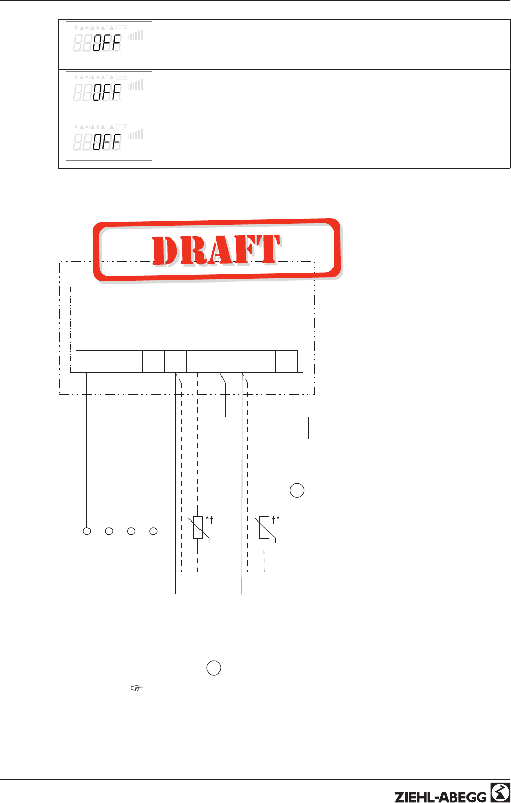
D1
Status digital input 1 (Digital In 1)
OFF = terminals D1 - 24 V bridged ↔ ON = terminals D1 - 24 V not bridged
D2
Status digital input 2 (Digital In 2)
OFF = terminals E1 - D24 bridged ↔ ON = terminals D2 (E2) - 24 V not bridged
K1
OFF = relay K1 de-energized: terminals 11 - 14 not bridged
ON = relay K1 energized: terminals 11 - 14 bridged
12 Enclosure
12.1 Connection diagram
AM-PREMIUM
GND24V E2 T2
MOSI11K0
21.03.2011
A
(D+)
B
(D-)
GND24 V
GND
Eingang
Input
+
1
2
E3 T3 A1
Ausgang
Output
0...10 V
+
2
+
3
q
TF..
DC Out
(Imax = 70 mA)
q
TF..
Analog In 2
Analog In 3
Analog Out 1
(Imax = 6 mA)
Eingang
Input
KTY 81-210 / PT 1000
KTY 81-210 / PT 1000
0...10 V (Ri > 100 kΩ)
0...20 mA (Ri = 250 Ω)
4...20 mA (Ri = 250 Ω)
MODBUS
(RS-485)
Further connections
connection diagram in operating instructions ECblue Basic
Operating Instructions AM-PREMIUM / AM-PREMIUM-W – model series Enclosure
L-BAL-E095-GB 1203 Index 004 Part.-No.
66/68

Operating Instructions AM-PREMIUM / AM-PREMIUM-W – model series Enclosure
L-BAL-E095-GB 1203 Index 004 Part.-No.
67/68
12.2 Index
A
address 52
Average calculation 21
B
Base setup 41
D
D-component 41
diagnostics menu 65
Digital inputs 43
DSG 29
E
Enable 44
External Setpoint 17
G
group control 40
H
Holding Registers 52
I
I-component 41
K
K Factor 32
L
Limit 39
Limits 52
M
MAL1, MAL10 34
MBG-30I, MBG-50I 26
Minimum speed cut off 39
MODBUS 9
Mode 16
O
outputs 0 - 10 V 7
P
P-component 41
pin code 36
PIN input 36
PIN protection 38
PT1000 7
R
Rampdown time 56
Rampup time 56
refrigerant 27
Relay output 9
Reset 44
resonances 57
S
Suppression 3, 57
T
terminal 8
two-wire-technology 7
U
user settings 38

12.3 Manufacturer reference
Our products are manufactured in accordance with the relevant international regulations. If you have
any questions concerning the use of our products or plan special uses, please contact:
Ziehl-Abegg AG
Heinz-Ziehl-Straße
74653 Künzelsau
Telephone: +49 (0) 7940 16-0
Telefax: +49 (0) 7940 16-504
info@ziehl-abegg.de
http://www.ziehl-abegg.de
12.4 Service information
If you have any technical questions while commissioning or regarding malfunctions, please contact
our V-STE support department for control systems - ventilation technology.
Our worldwide contacts are available in our subsidiaries for deliveries outside of Germany.
www.ziehl-abegg.com.
If you make returns for inspections or repairs we need certain information in order to facilitate focused
trouble shooting and fast repair. Please use our repair tickets for this. It is provided to you after you
have consulted our support department.
In addition, you can download it from our homepage. Download - Ventilation Technology - Topic:
Control Engineering - Document type: General documents.
Operating Instructions AM-PREMIUM / AM-PREMIUM-W – model series Index
L-BAL-E095-GB 1203 Index 004 Part.-No.
68/68