Zinwave 305-0007 305-0007 Distributed Antenna System Remote Unit User Manual InstallandConfig
Zinwave Ltd 305-0007 Distributed Antenna System Remote Unit InstallandConfig
Zinwave >
Contents
- 1. Users manual
- 2. Users manual 1
- 3. Users manual 2
- 4. Users manual 3
Users manual

UNItivity 5000
In-Building Wireless Solution
Installation and Configuration
Software Version 5
© 2016-2018 Zinwave Ltd
All Rights Reserved
Zinwave retains all ownership rights to all computer programs offered by Zinwave, their products, and the contents
of this manual. The source code for both software and firmware are confidential trade secrets of Zinwave. You may
not attempt to decipher, decompile, develop or otherwise reverse engineer Zinwave software, firmware, or
products. Information necessary to achieve interoperability is furnished upon request.
This manual is furnished under license and may only be used or copied in accordance with the terms of such
license. The information in the manual is furnished for informational use only, is subject to change without notice,
and should not be construed as commitment by Zinwave. Zinwave assumes no responsibility or liability for any
errors or inaccuracies that may appear in this manual. No part of this manual may be reproduced, stored in a
retrieval system, or transmitted, in any form or by any means, electronic, mechanical, recording, or otherwise,
without the express written permission of Zinwave.
Existing artwork or images that you may desire to scan may be protected by copyright law. Be sure to obtain
permission for use of existing artwork.
Trademarks
This product carries the Trademark of Zinwave,Ltd. All the trademarks of component parts used by Zinwave in the
manufacture of this product are the property of their respective owners. The Zinwave logo is a registered
trademark of Zinwave
Pentium® is a registered trademark of Intel Corporation. Adobe® is a trademark of Adobe Systems Incorporated.
All versions are U.S. registered trademarks of Microsoft Corporation. Macintosh is a trademark of Apple Computer.
Linux is a trademark of Linus Torvalds.
All brand or product names are trademarks or registered trademarks of their respective companies or
organizations.
Warranty
The material contained in this document is provided “as is,” and is subject to being changed, without notice, in
future editions. Further, to the maximum extent permitted by applicable law, Zinwave disclaims all warranties,
either express or implied, with regard to this manual and any information contained herein, including but not limited
to the implied warranties of merchantability and fitness for a particular purpose. Zinwave shall not be liable for
errors or for incidental or consequential damages in connection with the furnishing, use, or performance of this
document or of any information contained herein. Should Zinwave and the user have a separate written agreement
with warranty terms covering the material in this document that conflict with these terms, the warranty terms in the
separate agreement shall control
ZWSystemOverviewV2_22717

Table of Contents
Safety and Regulatory Information ...................................................... i
About this Manual ............................................................................. xiii
Chapter 1: System Overview ........................................................... 1-1
1.1 How Does It Work? .................................................................................... 1-1
1.1.1. Real World Examples ........................................................................ 1-2
1.1.1.1. Single Building Example ............................................................ 1-2
1.1.1.2. Campus Example ...................................................................... 1-3
1.2 Key Features. ............................................................................................. 1-4
1.3 Network Topologies .................................................................................... 1-4
1.3.1. Single Star Configuration ................................................................... 1-5
1.3.2. Double Star Configuration .................................................................. 1-5
1.3.3. Network Cabling ................................................................................. 1-6
1.3.4. Support For MIMO Services ............................................................... 1-6
1.4 Understanding Optional Components ........................................................ 1-9
1.4.1. How the PSU Fits in ........................................................................... 1-9
1.4.2. How the Active POI Fits in ................................................................. 1-9
1.4.3. How the Small Cell POI Fits in ......................................................... 1-10
1.5 Understanding Service Distribution .......................................................... 1-10
Chapter 2: Understanding the Components ................................... 2-1
2.1 Hub ............................................................................................................. 2-1
2.1.1. Primary Hub. ...................................................................................... 2-1
2.1.1.1. Front View ................................................................................. 2-2
2.1.1.2. Rear View. ................................................................................. 2-3
2.1.2. Secondary Hub .................................................................................. 2-3
2.1.2.1. Rear View. ................................................................................. 2-4
2.2 Service Module........................................................................................... 2-4
2.2.1. Front View .......................................................................................... 2-5
2.2.2. Rear View .......................................................................................... 2-5
2.3 Optical Module ........................................................................................... 2-5
2.3.1. Front View .......................................................................................... 2-6
2.3.2. Rear View .......................................................................................... 2-7
2.4 Remote Unit ............................................................................................... 2-7
2.4.1. Bottom View ....................................................................................... 2-8
2.4.2. Top View ............................................................................................ 2-8
2.4.3. Antennas ............................................................................................ 2-8
2.5 Fiber Patch Cords ...................................................................................... 2-8
2.6 Central 48V PSU (Optional) ....................................................................... 2-9
TOC-1
2.6.1. 2U - 600W ........................................................................................ 2-10

2.6.1.1. Front View ............................................................................... 2-10
2.6.1.2. Rear View. ............................................................................... 2-10
2.6.2. 1U - 600W ........................................................................................ 2-11
2.6.2.1. Front View ............................................................................... 2-11
2.6.2.2. Rear View. ............................................................................... 2-11
2.7 POI (Optional) .......................................................................................... 2-12
2.7.1. Active POI. ....................................................................................... 2-12
2.7.2. Small Cell POI .................................................................................. 2-12
2.7.3. Front View ........................................................................................ 2-13
2.8 Configuration GUI ..................................................................................... 2-14
Chapter 3: Hub and Hub Module LEDs ........................................... 3-1
3.1 Hub Front Panel LEDs ............................................................................... 3-1
3.2 Service and Optical Module LEDs .............................................................. 3-1
3.2.1. Power LED - Right ............................................................................. 3-2
3.2.2. Communications - Middle ................................................................... 3-2
3.2.3. Status - Left ........................................................................................ 3-3
3.3 Start-up Sequence ..................................................................................... 3-4
3.3.1. Service Module .................................................................................. 3-4
3.3.2. Optical Module. .................................................................................. 3-4
3.4 Remote Unit LEDs ...................................................................................... 3-5
Chapter 4: Performing a Basic Installation ..................................... 4-1
Chapter 5: Installing and Populating Hubs ..................................... 5-1
5.1 Installing the Hub ........................................................................................ 5-1
5.1.1. Mounting Kit. ...................................................................................... 5-1
5.1.2. Standard 19" Rack Mounting ............................................................. 5-2
5.1.3. Open Frame Rack Mounting .............................................................. 5-2
5.1.4. Installing Blank Panels ....................................................................... 5-3
5.2 Installing Service Modules (Primary only)................................................... 5-4
5.3 Installing Optical Modules .......................................................................... 5-4
5.4 Powering the Hub ....................................................................................... 5-5
5.4.1. AC Powered Hub ............................................................................... 5-5
5.4.2. DC Powered Hub. .............................................................................. 5-6
Chapter 6: Installing Remote Units ................................................. 6-1
6.1 Mounting Remote Units .............................................................................. 6-1
6.2 Powering Remote Unit ............................................................................... 6-3
6.2.1. AC Power ........................................................................................... 6-3
TOC-2 Installation and Configuration
6.2.2. PSU DC Power .................................................................................. 6-3
6.2.2.1. Rack Mount the PSU ................................................................. 6-3
6.2.2.2. Applying DC power to the Remote Unit ..................................... 6-4

Chapter 7: Understanding Antennas .............................................. 7-1
7.1 Antenna Requirements ............................................................................... 7-1
7.1.1. Isolation ............................................................................................. 7-1
7.1.2. Isolation Measurement Techniques ................................................... 7-2
7.1.3. Uplink/Downlink Balance ................................................................... 7-4
7.2 Connecting Antenna to Remote Units ........................................................ 7-4
Chapter 8: Infrastructure and Cabling ............................................ 8-1
8.1 Understanding Fiber Infrastructure Cabling ................................................ 8-1
8.1.1. Selecting an Infrastructure Mode ....................................................... 8-2
8.1.2. Use of Singlemode or Multimode Fiber cable .................................... 8-3
8.1.2.1. Fiber and Connector Specifications ........................................... 8-4
8.1.3. Infrastructure Interface ....................................................................... 8-4
8.2 Fiber Optic Connectors .............................................................................. 8-5
8.2.1. Ferrule Types ..................................................................................... 8-6
8.2.1.1. APC (Angled Physical Contact) ................................................. 8-7
8.2.1.2. UPC (Ultra-polished Physical Contact) ...................................... 8-7
8.2.1.3. PC (Physical Contact) ................................................................ 8-7
8.3 Handling Optical Fiber ................................................................................ 8-8
8.4 Diagnosing Fiber connections .................................................................... 8-8
8.5 Link Calibration........................................................................................... 8-8
Chapter 9: Making Connections ...................................................... 9-1
9.1 Connecting Service Modules to RF inputs or POI ...................................... 9-1
9.2 Connecting Optical Modules....................................................................... 9-1
9.2.1. Infrastructure and Other Optical Modules .......................................... 9-1
9.2.2. Optical Modules to Remote Units ....................................................... 9-2
9.3 Connecting the PSU to Remote Units ........................................................ 9-2
9.3.1. CAT5/Power Distribution Requirements............................................. 9-2
9.3.2. Understanding the Cabling ................................................................. 9-3
9.4 Connecting the PSU to a Hub .................................................................... 9-4
9.5 Grounding Rack Mounted Equipment ........................................................ 9-5
Installation and Configuration
TOC-3

Chapter 10: Performing Basic Configuration ............................... 10-1
Chapter 11: Understanding the Configuration GUI ...................... 11-1
11.1 Supported Browsers ............................................................................... 11-1
11.2 Initial Stand-alone Access ...................................................................... 11-1
11.3 Accessing the GUI .................................................................................. 11-1
11.4 Understanding the Main Window ............................................................ 11-3
11.4.1. Address Bar ................................................................................... 11-3
11.4.2. Left-Navigation Area ...................................................................... 11-4
11.4.3. Login Bar ........................................................................................ 11-4
11.4.4. Help Button .................................................................................... 11-4
11.4.5. Display Area................................................................................... 11-4
11.4.6. Progress Indicator .......................................................................... 11-4
11.5 Changing User Passwords and Timeouts .............................................. 11-5
Chapter 12: Initial System Setup ................................................... 12-1
12.1 Setting the Hub Type .............................................................................. 12-1
12.2 Update Firmware .................................................................................... 12-1
12.2.1. Individual Hub Upgrade ................................................................. 12-2
12.2.2. Full System Hub Upgrade .............................................................. 12-3
12.3 Remote Unit Upgrade ............................................................................. 12-4
12.3.1. Individual Remote Unit Upgrade .................................................... 12-4
12.3.2. Full System Remote Unit Upgrade ................................................. 12-6
12.4 Setting Hub Date and Time. ................................................................... 12-7
12.5 User Interface Settings ........................................................................... 12-8
12.6 LAN Settings for Hubs ............................................................................ 12-8
12.6.1. IP Settings ...................................................................................... 12-8
12.7 PSU Setup ........................................................................................... 12-10
Chapter 13: Understanding System Status ................................... 13-1
13.1 Viewing System Status ........................................................................... 13-1
13.2 Interpreting System Status ..................................................................... 13-2
13.2.1. Colors and Symbols ....................................................................... 13-3
13.2.2. Hub Status ..................................................................................... 13-3
13.2.3. Remote Unit Status ........................................................................ 13-4
13.3 System Tools.......................................................................................... 13-7
13.3.1. View System Layout....................................................................... 13-8
13.3.2. View Event Log. ............................................................................. 13-9
13.3.3. View Link Quality For Remote Units ............................................. 13-10
13.3.4. View Remote Unit DC Power ....................................................... 13-10
13.3.5. RU Calculations ........................................................................... 13-11
TOC-4 Installation and Configuration

Chapter 14: Understanding System Setup ................................... 14-1
14.1 Managing Links by Viewing Status ......................................................... 14-2
14.1.1. Understanding Poor Optical Links .................................................. 14-4
14.2 Inputting System Values ......................................................................... 14-5
14.3 System Uplink/Downlink Balance ......................................................... 14-11
14.4 Calculated Input Level .......................................................................... 14-12
14.5 Remote Unit Downlink Power ............................................................... 14-13
14.6 Remote Unit Uplink Power Max ............................................................ 14-14
14.7 Changing or Swapping Equipment ....................................................... 14-14
14.7.1. Hub .............................................................................................. 14-14
14.7.2. Remote Unit ................................................................................. 14-15
14.7.3. Optical Module. ............................................................................ 14-15
Chapter 15: Understanding Hub Setup ......................................... 15-1
15.1 Configuration Files ................................................................................. 15-1
15.2 Restarting the Hub ................................................................................. 15-3
15.3 Factory Reset of a Hub .......................................................................... 15-3
15.4 Remote Unit Settings ............................................................................. 15-5
15.4.1. RU Uplink Sensitivity ...................................................................... 15-5
15.5 Service Module Downlink Sensitivity ...................................................... 15-8
Chapter 16: Understanding Alarms and Reporting ...................... 16-1
16.1 Alarms .................................................................................................... 16-1
16.1.1. Loss of service. .............................................................................. 16-1
16.1.1.1. Loss of Service Alarms .......................................................... 16-2
16.1.2. Service Warning ............................................................................. 16-2
16.1.2.1. Service Warning Alarms ........................................................ 16-3
16.1.3. Hardware Warning. ........................................................................ 16-4
16.1.3.1. Hardware Warning Alarms ..................................................... 16-5
16.1.4. Informational .................................................................................. 16-6
16.2 Alarm Handling ....................................................................................... 16-7
16.2.1. Clearing Relays .............................................................................. 16-7
16.2.2. Alarm Handling Configuration ........................................................ 16-7
16.3 Alarm Connections ................................................................................. 16-9
16.4 SNMP ................................................................................................... 16-10
16.4.1. Snmp Trap Events ....................................................................... 16-10
16.4.2. SNMP Get Objects ....................................................................... 16-10
16.4.3. SNMP Traps ................................................................................ 16-11
16.4.4. SNMP Settings ............................................................................. 16-11
Installation and Configuration
TOC-5

Chapter 17: Performing Diagnostics and Testing ......................... 17-1
17.1 Diagnosing Optical Links with an OTDR................................................. 17-1
17.1.1. Diagnose an Optical Link ............................................................... 17-1
17.2 LED Testing ........................................................................................... 17-2
17.2.1. Modules ......................................................................................... 17-2
17.2.2. Remote Unit LED Test ................................................................... 17-3
17.3 Event Log ............................................................................................... 17-3
17.3.1. Viewing and saving the Event Log ................................................. 17-3
17.3.2. Logging Events to a USB ............................................................... 17-4
17.4 Interpreting System Layout Tables ......................................................... 17-5
17.4.1. Converting the System Layout File to Excel ................................... 17-6
17.4.2. Interpreting the Excel File .............................................................. 17-8
17.4.2.1. System Layout Sheet ............................................................. 17-8
17.4.2.2. Autosetup Sheet. ................................................................... 17-9
17.4.2.3. Link Quality ............................................................................ 17-9
17.4.2.4. Misc ....................................................................................... 17-9
17.4.2.5. Tables .................................................................................... 17-9
Chapter 18: Preventive Maintenance and Cleaning ..................... 18-1
18.1 General Equipment Cleaning and Inspection ......................................... 18-1
18.2 Hardware Maintenance Frequency Guidelines....................................... 18-1
18.3 General Cleanliness and Rack Mounted Equipment .............................. 18-2
18.4 Fiber Cleaning and Inspection ................................................................ 18-2
18.4.1. Inspection....................................................................................... 18-2
18.4.1.1. Insertion Loss ........................................................................ 18-2
18.4.1.2. Optical Return Loss (Back Reflections) ................................. 18-3
18.4.2. Cleaning Fibers .............................................................................. 18-3
18.4.2.1. Dry Cleaning .......................................................................... 18-4
18.4.2.2. Wet Cleaning. ........................................................................ 18-4
18.5 Antenna Cables and Connections .......................................................... 18-4
Chapter 19: Specifications. ............................................................ 19-1
Chapter 20: Glossary ..................................................................... 20-1
TOC-6 Installation and Configuration
Safety and Regulatory Information
Safety Information
The following safety warnings cautions are listed to prevent damage to equipment or property and prevent
any risk of personal injury.
Warning: Dispose of all waste properly as per federal, state, and local waste disposal
regulations. Improper disposal could result in personal injury and environmental impact.
Warning: If this product is not used as specified, the protection provided by the equipment could
be impaired. This product must be used only in a normal condition (in which all means for
protection is intact).
Warning: Before using the device, read through this entire manual. Attempting to use this
device without a thorough understanding of its operation may result in injury.
Warning: To prevent electrical shock, do not remove the covers. Opening or tampering with
sealed modules will invalidate the warranty.
Caution: No operator serviceable parts inside the sealed unit. If service is needed call Zinwave
Caution: The Hub is a “Class A” product (as defined in EN 55022). In a domestic
environment this product may cause radio interference, in which case the user may be required
to take adequate measures.
Caution: For continued protection against risk of fire, replace the exterior accessible fuse only
with same type and rating of fuse.
Caution: Position the power cord to avoid possible damage; do not overload wall outlets. Use
only the supplied power cord.
Caution: Do not place this product on or near a direct heat source, and avoid placing objects on
the terminal.
Caution: Use only a damp cloth for cleaning. Do not use liquid or aerosol cleaners. Disconnect
the power before cleaning.
Caution: Installation of UNItivity must be contracted to a suitably trained and competent
professional installer.
Caution: Do not over-tighten the hardware.
Caution: UNItivity is designed to operate in conditions conformant with Pollution Degree 2
as defined in IEC 60950 (the normal environmental class for offices).
i
Caution: The installation of sub-assemblies into the main units of UNItivity shall only be
undertaken if precautions required by IEC/TS 61340-5-1 have been taken.
Electricity Supply
Warning: Insulation on electrical wiring can deteriorate with age. Check for brittle or
deteriorated insulation on power cord and all other electrical wiring.
Warning: CLASS I PLUGGABLE EQUIPMENT TYPE A as defined in IEC 60950. This
equipment is intended for connection to other equipment or a network, relies on connection
to protective earth and must be connected to an earthed mains socket-outlet.
Country specific warnings:
Finland "Laite on liitettŠvä suojamaadoituskoskettimilla varustettuun pistorasiaan"
Norway “Apparatet må tilkoples jordet stikkontakt”
Sweden "Apparaten skall anslutas till jordat uttag
Warning: Do not excessively bend, twist, or tie the power cable. Do not place any heavy
items on the power cable or place any sources of heat near to the equipment, as damage to
the power cord could cause malfunction or fire.
Caution: The installation of electrical supplies in support of UNItivity products shall be in
accordance with national and local regulations.
Caution: DOUBLE POLE/NEUTRAL FUSING in Primary Hub.
Rack Mounting
Caution: Do not over-tighten the hardware.
Caution: Elevated Operating Ambient – Installing the equipment in an environment
compatible with the maximum ambient temperature listed in the specifications.
Caution: Reduced Air Flow – Install the equipment with adequate of air flow required for
safe operation.
Caution: Mechanical Loading – Do not load unevenly.
Caution: Circuit Overloading – Consider equipment nameplate ratings when connecting
equipment to the supply circuit. Overloading of the circuits might have and effect on
overcurrent protection and supply wiring.
Caution: Reliable Earthing – Maintain reliable earthing of rack-mounted equipment.
Particular attention should be given to supply connections other than direct connections to
the branch circuit (e.g. use of power strips).
Caution: Disconnect Device – The socket outlet shall be installed near the equipment, be
easily accessible, and will act as the main point of disconnect for the Hubs.
Caution: Manual Handling – Installation should be carried out by two competent personnel
as the equipment is heavy.
ii Installation and Configuration
Caution: Hubs are heavy rack units which must be supported at the front when installed into
a 19" rack. To avoid damage to the equipment do not support the whole weight using only 1
handle.
RF Exposure
Warning: This equipment complies with FCC radiation exposure limits set forth for an
occupational/ controlled environment. The Remote Unit should be operated with a minimum
distance of 20cm (8 in) between antenna and your body.
Installation
Caution: Incorrect installation, operation, and use of this equipment may cause failure to
product and could cause accidents which may harm personnel.
Caution: Optical Module must ONLY be installed on the front panel of a Primary Hub or the
unit will not function as expected.
Caution: Remote Units should be vertically-mounted to ensure optimum cooling effect and
to achieve the maximum ambient operating specification. If the Remote Units mounted in
the horizontal plane the maximum ambient operating temperature must be relaxed by 8°C
(47 F)
Signal and Input Power
Warning: If the service module is connected directly to the output of a BTS or any RF input
source, maximum power delivered to a service module must not exceed 15dBm. Use
additional equipment to attenuate the power.
Caution: The input power to the Zinwave Remote Unit should not exceed -10dBm. Power
levels greater than 0dBm will damage the unit
Caution: The total broadband composite output power of the Remote Unit is limited to +18
dBm in Europe and +20 dBm in the USA and Canada. The maximum allowed EIRP in the
USA & Canada is +28 dBm which corresponds to an antenna gain of 8 dBi. Contact
Zinwave for the maximum output power in other regions
Caution: Alarm Relays on the Hubs and Remote Unit are intended for low voltage/current
signaling only. Maximum operating voltage 50V, maximum operating current 1A.
Fiber Considerations
Caution: Avoid dust ingress to fiber connectors by mounting the Remote Unit with the fiber
connector facing downwards, or by leaving the dust-caps in place until the fiber is
connected.
Caution: Connector types must match (i.e. SC/APC to SC/APC or SC/UPC to SC/UPC).
Otherwise, there will be an air gap between the connector faces that will create high back
reflection and high optical loss.
Installation and Configuration iii
Caution: If there is a change in fiber core diameter, light must always travel from a smaller
to a larger core diameter. Otherwise, there will be excessive optical loss. E.g. Singlemode
can transmit into Multimode fiber but Multimode CANNOT transmit into Singlemode
Caution: Fiber handling procedures should be carefully observed so as not to damage or
introduce dirt to fiber interfaces during installation
Caution: Observe safety precautions when working with fiber cables and devices.
Optical Safety Precautions
Warning: Use of controls or adjustments or performance of procedures other than those
specified herein may result in hazardous radiation exposure.
Caution: Do not remove the fiber Port dust covers unless the port is in use. Do not stare
directly into a fiber Port.
Caution: Cover any unconnected fiber ends with an approved cap.
Caution: Do not stare with unprotected eyes at any broken ends of the fiber.
Caution: Use only approved methods for cleaning optical fiber connectors.
Caution: Do not make any unauthorized modifications to this fiber optical system.
Caution: No warning signs are required as it is a Class 1 hazard.
Caution: Use Class 1 test equipment.
iv Installation and Configuration
Software Installation
Caution: When new firmware is being installed it is very important not to break or interrupt
the connection between source file and the Hub. Interrupting firmware installation may put
the Hub into an irrecoverable state that requires factory reset.
Caution: While the system can be configured with poor optical links present, this may affect
the system performance and such links should be examined and brought into specification in
order to obtain optimum performance.
Symbols
This section identifies the symbols that are displayed on UNItivity devices. Labels or symbols may not
appear on every device.
Consult Manual
Electric shock hazard
UL certified UL NRTL Listing
The European CE mark
USB Port
Ethernet Port
Installation and Configuration v
ISO 9001certified
Symbol Description

Electrostatic Discharge Sensitive
This symbol indicates that the waste of electrical and
electronic equipment must not be disposed as unsorted
municipal waste and must be collected separately. Please
contact an authorized representative of the manufacturer for
information concerning the decommissioning of your
equipment. (WEEE)
Regulatory Information
•
EN 50174/50173 series: Information technology – Cabling installation
•
ANSI/TIA/EIA-568 series North America Cabling
•
ISO/IEC 11801 - International cabling
•
IEC 60825-2: Safety of laser products – Part 2: Safety of optical fiber communication systems
(OFCS)
•
This equipment complies with 21CFR1040 - Performance Standards For Light-Emitting
Products (FDA).
•
EN 55032/CISPR32
•
FCC Part 15 Class A
•
European Radio Equipment Directive 2014/53/EU
•
Electrical Safety IEC 60950-1
•
Laser Safety EN 60825-1:2007
•
ISO 9001
•
UL-60950-1
•
RoHS DIRECTIVE 2011/65/EU
•
UL2043 compliance
In reference to UL2043 compliance, Remote Units are suitable for use in environmental air space in
accordance with Section 300-22(c) of the National Electrical Code, and Sections 2-128, 12-010(3) and
12-100 of the Canadian Electrical Code, Part 1, CSA C22.1.
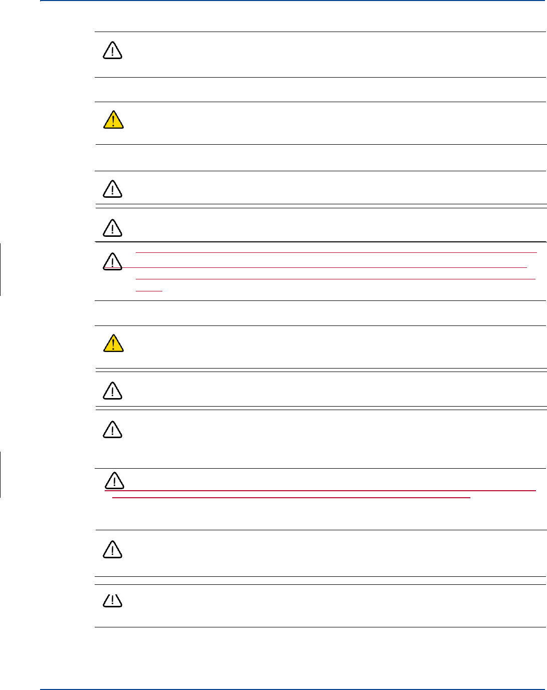
Note: The system contains a device which is classified as a “CLASS I LASER PRODUCT”, with an
internal Class 1 laser source (as defined in CBTR # DE3-500286 by TUV). The component
within the unit is in compliance with “U.S. Code of Federal Regulations, 21 CFR 1040”. See the
Detailed Data Sheet for label placement.
UL NRTL listing
UNItivity has been tested and shown to meet UL and CSA requirements through testing carried out at
a Nationally Recognized Testing Laboratory (NRTL). The UL certification Mark indicates national
compliance to UL and CSA standards by virtue of accreditations obtained.
Product: Distributed Antenna System
Model: UNItivity, Hub and Remote Unit
UL Listing ID: E486578
vi Installation and Configuration
Symbol Description
FCC
FCC compliance and interference statements
Hub: UNItivity devices comply with Part 15 of the FCC rules. Operation is subject to the following two
conditions:
1)
This device must accept any interference and
2)
This device must accept any interference received including interference that may cause
undesired operation
Changes or modifications not expressly approved by Zinwave Ltd. could void the user’s authority to
operate the equipment.
Remote Unit: This device complies with Part 22, Part 24, Part 27, Part 74 and Part 90 of the FCC
rules. Changes or modifications not expressly approved by Zinwave Ltd. could void the user’s
authority to operate the equipment. For a list of services, please contact Zinwave.
•
This device must only be used with antennas having a maximum gain of 8 dBi
•
When operating on channel or channels under 47CFR part 90 as identified in the table below,
this is a
Class B booster as defined in 47CFR90.219.
Class B boosters must be registered with the FCC prior to operation, which can be done at the
FCC Part 90 Class B Signal Booster Registration & Discovery website:
https://signalboosters.fcc.gov/signal-boosters/
Warning: This is NOT a CONSUMER device. It is designed for installation by FCC
LICENSEES and QUALIFIED INSTALLERS. You MUST have an FCC LICENSE or express
consent of an FCC Licensee to operate this device. You MUST register Class B signal
boosters (as defined in 47 CFR 90.219) online at www.fcc.gov/signal-boosters/registration.
Unauthorized use may result in significant forfeiture penalties, including penalties in excess
of $100,000 for each continuing violation.
•
When operating on channel or channels under 47CFR parts 22, 24, 27 or 74 as identified in
the table below, this is an Industrial Booster as per 47CFR part 20.
Warning: This is NOT a CONSUMER device. It is designed for installation by FCC
LICENSEES and QUALIFIED INSTALLERS. You MUST have an FCC LICENSE or express
consent of an FCC Licensee to operate this device. Unauthorized use may result in
significant forfeiture penalties, including penalties in excess of $100,000 for each continuing
violation.
Installation and Configuration vii

Remote Unit with FCC ID: FCC ID UPO302-1107 only supports services in the following bands of
operation:
Rule Downlink Frequency
Part Band Range (MHz) Service Modulation
90
VHF Public Safety
150.8 – 156.2475
157.1875 – 161.575
161.775 – 161.9625
162.0125 – 173.4
P25
C4FM (QPSK)
FM
FM ±2.5kHz dev'n
UHF Public Safety
406.1 - 420
421 - 430
P25
C4FM (QPSK)
FM
FM ±2.5kHz dev'n
FM
FM ±5.0kHz dev'n
456.0 – 462.5375
462.7375 - 467.5375
467.7375 - 512.0
P25
C4FM (QPSK)
FM
FM ±2.5kHz dev'n
FM
FM ±5.0kHz dev'n
74
UHF PMSE
470 – 608
614 – 679.9
FM
FM ±75kHz dev'n
90
700MHz Public
Safety
769 – 775
758-768
698 - 758
P25
C4FM (QPSK)
OpenSky
4-level GFSK
Band 14
LTE
64 QAM
27
700MHz LTE
LTE
64 QAM
90
22
800MHz Public
Safety
851 – 854, 854- 861
862 - 869
851 – 854, 854- 861
862 - 869
P25
C4FM (QPSK)
OpenSky
4-level GFSK
800MHz SMR
FM & EDACS
FM ±5.0kHz dev'n
900MHz ESMR
935 - 940
LTE
64-QAM
800MHz ESMR
854 – 861
862 - 869
869 - 894
929 - 930
EVDO
(QPSK+QAM)
QPSK + QAM
FD-LTE
QPSK + QAM
Cellular
UMTS
QPSK
HSPA/HSPA+
16-QAM/64-QAM
CDMA
QPSK
CDMA2000
Ev-DO
8PSK, 16-QAM
929 Paging
FSK
FSK
931 Paging
931 - 932
FSK
FSK
viii Installation and Configuration
xxxxxxxxxxxxx
UPO305-0007

Rule Downlink Frequency
Part Band Range (MHz) Service Modulation
24
PCS
1930 - 1995
GSM
GMSK
EDGE
8-PSK
UMTS
QPSK
HSPA/HSPA+
16-QAM/64-QAM
FDD LTE (band
2/25)
QPSK + QAM
CDMA
QPSK
CDMA2000
Ev-DO
8PSK, 16-QAM
27
AWS
2110 - 2180
UMTS
QPSK
HSPA/HSPA+
16-QAM/64-QAM
FD-LTE (band
4)
16-QAM/64-QAM
FD-LTE (band
10)
16-QAM/64-QAM
AWS-4
2180 – 2200
FD-LTE
16-QAM/64-QAM
WCS
2345 - 2360
FD-LTE
16-QAM/64-QAM
BRS/EBS
2496 – 2690
LTE
16-QAM/64-QAM
The Remote Unit is a Licensed Transmitter with authorization to transmit the services. See the
Technical Specification for more information.
FCC Cautionary note
Any changes or modifications in construction of this equipment which are not expressly approved by
the party responsible for compliance could void the user's authority to operate the equipment.
FCC Verification : Primary and Secondary Hub
This device complies with part 15 of the FCC Rules. Operation is subject to the followings two
conditions: (1) This device may not cause harmful interference, and (2) this device must accept any
interference received, including interference that may cause undesired operation.
This is a Class A Digital Device
This equipment has been tested and found to comply with the limits for a Class A digital device,
pursuant to part 15 of the FCC rules. These limits are designed to provide reasonable protection
against harmful interference when the equipment is operated in a commercial environment. This
equipment generates, uses, and can radiate radio frequency energy and, if not installed and used in
accordance with the instruction manual, may cause harmful interference to radio communications.
Operation of this equipment in a residential area is likely to cause harmful interference in which case
the user will be required to correct the interference at his own expense.
Note: This is Class A product (as defined in EN 55032). In a domestic environment this product may
cause radio interference, in which case the user may be required to take adequate measures.
Installation and Configuration ix
xxxxxx
xxxxxxx
xxxxxx
xxxxxx

Innovation, Science and Economic Development Canada compliance statement
The nominal passband gain is 25 dB and the nominal bandwidth is 150 MHz to 2.94 GHz. The rated
mean output power is 20 dBm and the input and output impedances are 50 ohms.
The Manufacturer's rated output power of this equipment is for single carrier operation. For situations
when multiple carrier signals are present, the rating would have to be reduced by 3.5 dB, especially
where the output signal is re-radiated and can cause interference to adjacent band users. This power
reduction is to be by means of input power or gain reduction and not by an attenuator at the output of
the device.
WARNING: This is NOT a CONSUMER device. It is designed for installation by an
installer approved by an ISED licensee. You MUST have an ISED LICENCE or the
express consent of an ISED licensee to operate this device.
CE Information
UNItivity complies with the essential requirements of the Radio Equipment Directive (2014/53/EU) and
is therefore ‘CE’ marked when it is used in accordance with the instructions provided in this Manual.
CE Declaration of Conformity
This equipment has been tested and found to comply with the limits set out by the Directive 2014/53/
EU.
Hereby, Zinwave Ltd, declares that this Distributed Antenna System is in compliance with the essential
requirements and other relevant provisions of Directive 2014/53/EU.
Zinwave Ltd, vakuuttaa tŠten että Distributed Antenna System tyyppinen laite on direktiivin 2014/53/
EU oleellisten vaatimusten ja sitä koskevien direktiivin muiden ehtojen mukainen.
Hierbij verklaart Zinwave Ltd, dat het toestel Distributed Antenna System in overeenstemming is met
de essenti‘le eisen en de andere relevante bepalingen van richtlijn 2014/53/EU
Bij deze verklaart Zinwave Ltd, dat deze Distributed Antenna System voldoet aan de essenti‘le eisen
en aan de overige relevante bepalingen van Richtlijn 2014/53/EU.
Par la prŽsente, Zinwave Ltd, dŽclare que ce Distributed Antenna System est conforme aux exigences
essentielles et aux autres dispositions de la directive 2014/53/UE qui lui sont applicables
HŠrmed intygar Zinwave Ltd, att denna Distributed Antenna System stŒr I šverensstŠmmelse med de
vŠsentliga egenskapskrav och švriga relevanta bestŠmmelser som framgŒr av direktiv 2014/53/EU.
Undertegnede Zinwave Ltd, erklærer herved, at følgende udstyr Distributed Antenna System
overholder de væsentlige krav og øvrige relevante krav i direktiv 2014/53/EU
Hiermit erklŠrt Zinwave Ltd., dass sich dieser Distributed Antenna System in †bereinstimmung mit den
grundlegenden Anforderungen und den anderen relevanten Vorschriften der Richtlinie 2014/53/EU
befindet
ΜΕ ΤΗΝ ΠΑΡΟΥΣΑ Zinwave Ltd, ∆ΗΛΩΝΕΙ ΟΤΙ Distributed Antenna System ΣΥΜΜΟΡΦΩΝΕΤΑΙ
ΠΡΟΣ ΤΙΣ ΟΥΣΙΩ∆ΕΙΣ ΑΠΑΙΤΗΣΕΙΣ ΚΑΙ ΤΙΣ ΛΟΙΠΕΣ ΣΧΕΤΙΚΕΣ ∆ΙΑΤΑΞΕΙΣ ΤΗΣ Ο∆ΗΓΙΑΣ 2014/53/
EE
Con la presente Zinwave Ltd, dichiara che questo Distributed Antenna System è conforme ai requisiti
essenziali ed alle altre disposizioni pertinenti stabilite dalla direttiva 2014/53/EU.

x Installation and Configuration
Por medio de la presente Zinwave Ltd, declara que el Distributed Antenna System cumple con los
requisitos esenciales y cualesquiera otras disposiciones aplicables o exigibles de la Directiva 2014/53/ UE
Zinwave Ltd, declara que este Distributed Antenna System está conforme com os requisitos
essenciais e outras disposi?›es da Directiva 2014/53/EU.
RoHs Information
This equipment fully complies with the requirements set out in the RoHS Directive. DIRECTIVE 2011/ 65/EU
Installation and Configuration xi

xii Installation and Configuration
About this Manual
This manual provides installation and configuration instructions for the UNItivity 5000 in-building wireless
solution. It describes installation of individual components, connection of each device to another, and
configuration of devices.
Intended Audience
The intended users for this manual are trained and competent in the professional installation of rack
mounted equipment and familiar with the configuration of Distributed Antenna Systems (DAS).
Conventions
Various types of pictures or icons are used in this service manual wherever they reinforce the printed
message to alert you to potential safety hazards in one of the following ways:.
Warning: A warning notice denotes a hazard. It calls attention to an operating
procedure, practice, or the like that, if not correctly performed or adhered to, could
result in personal injury or death. Do not proceed beyond a Warning notice until the
indicated conditions are fully understood and met.
Caution: A caution notice denotes a hazard. It calls attention to an operating
procedure, practice, or the like that, if not correctly performed or adhered to, could
result in damage to the product or loss of important data. Do not proceed beyond a
caution notice until the indicated conditions are fully understood and met.
Sensitive to electrostatic discharge caution: An Electrostatic Discharge (ESD)
Susceptibility symbol is displayed to alert personnel that the part(s) are sensitive to
electrostatic discharge and that static control procedures must be used to prevent
damage to the equipment.
Bold
Actions you should take such as text or data to be typed exactly or items to click.
Italics
Items to type for which you must supply a value.
Screen
Name
Screen Names are in initial caps.
Note: A note provides additional information to clarify a point in the text.
Important: An Important statement is similar to a note, but is used for greater emphasis.
Getting Help
Help for the Configuration GUI is available by clicking the Help button. If you need further assistance,
please contact Zinwave support at support@zinwave.com or your service partner.
xiii

xiv Installation and Configuration

Chapter 1: System Overview
Zinwave’s UNItivity 5000 in-building wireless solution provides cellular and public safety access
services to buildings, campuses, and venues, delivering end-to-end all fiber service on a single
converged system. Zinwave’s unique wideband architecture supports any service mix, protocol, or
modulation scheme from 150MHz to 2700MHz. UNItivity 5000 provides RF coverage over large areas
and supports a multitude of wireless and IP data services, irrespective of carrier frequency or signal
protocol.
The components of UNItivity 5000 are:
•
Primary Hub
•
Service Module - installed in Primary Hubs
•
Optical Module - installed in Primary Hubs
•
Secondary Hub – incorporates 48V DC Power Supply Unit (PSU) for Remote Units
•
Remote Unit
•
Configuration Graphical User Interface (GUI) - supplied on Primary Hubs
•
Active Point of Interface (POI) device (optional) - head-end connection between high power
RF source and Primary Hubs
•
Small Cell Point of Interface unit (Optional) - provides a simple head end connection
between a small cell (up to 4) and a Primary Hub
•
Central 48V DC Power Supply (Optional) – used for powering any Remote Units directly
connected to Primary Hub
The system’s network infrastructure uses standard structured cabling, broadband Single-mode optical
fiber.
1.1
How Does It Work?
At a high-level, the standard solution provides a complete in-building wireless infrastructure with a few
core components. Radio Frequency (RF) source inputs come into the Primary Hub’s Service Module
directly or through one of the optional POI products. The Primary Hub converts these RF signal inputs
to optical and connects via optical fiber directly to Remote Units or to a Secondary Hub. The
1-1
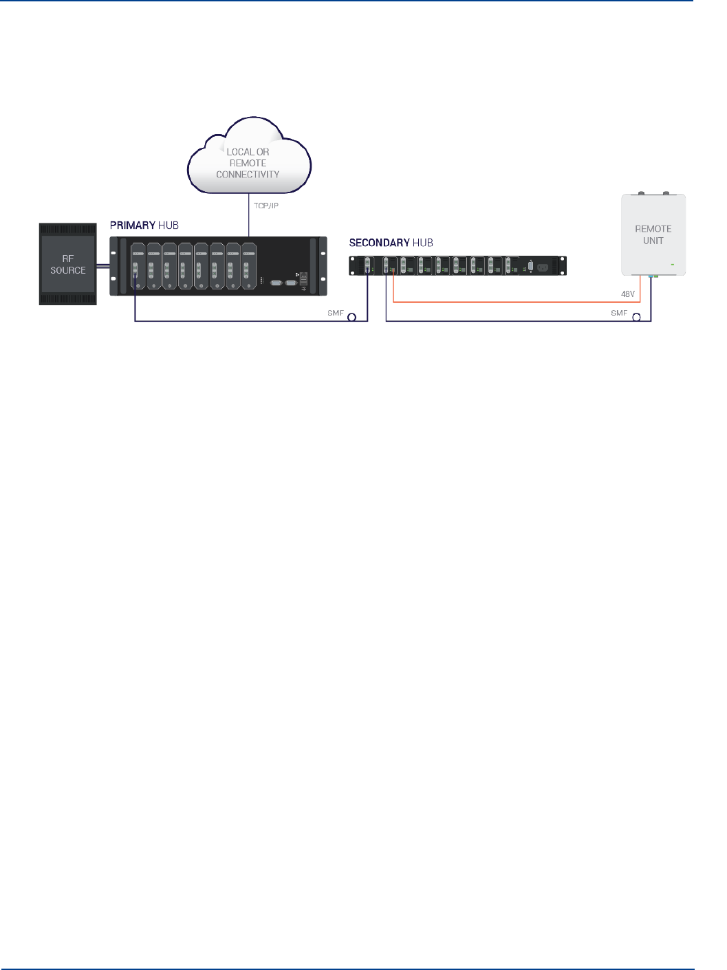
How Does It Work?
Secondary Hub connects via optical fiber directly to Remote Units. The Remote Units connect to
antennas, taking the optical signal back to RF and amplifying it for wider distribution.
System Overview
1.1.1. Real World Examples
The following illustrations show the UNItivity 5000 solution applied to a single building and across a campus.
1.1.1.1.
Single Building Example
In this illustration, the POI and Primary Hub are located in the basement with local access via a
laptop.The POI routes RF inputs into the Service modules on the rear of the Primary Hub. Remote
Units, scattered throughout the building, are connected to Optical Modules on the front of the Primary
Hub. A Secondary Hub, located on the upper floors, is also connected to the Primary Hub.
1-2 Installation and Configuration
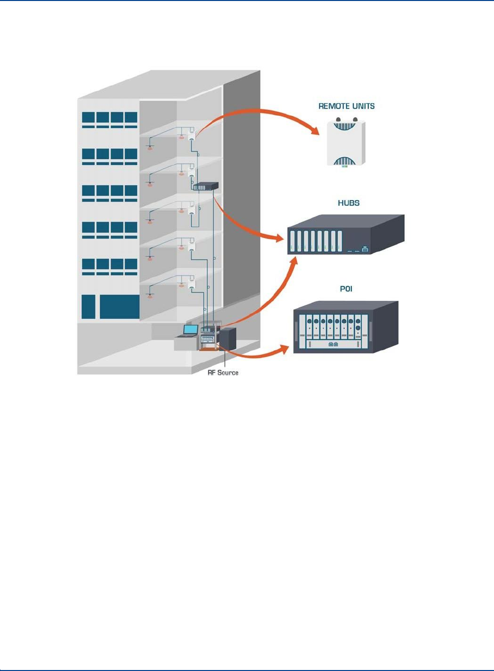
How Does It Work?
System Overview
Additional Remote Units are connected to the Secondary Hub. Antennas are placed in the ceilings and
connected to the Remote Units.
1.1.1.2.
Campus Example
In this illustration, the POI, Primary Hub, and Secondary Hub are located in the basement of the
building to the left. The POI routes RF inputs into the Service Modules on the rear of the Primary Hub.
Multiple Secondary Hubs are connected to the Optical Modules in the front of the Primary Hub. These
Secondary Hubs are located in buildings throughout the campus. Remote Units are connected to the
Installation and Configuration 1-3
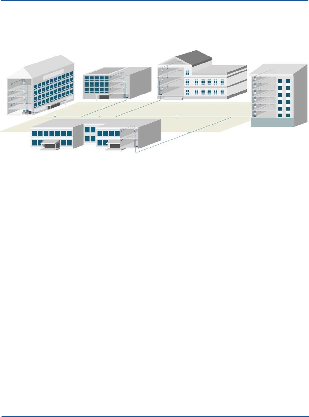
Key Features
System Overview
Secondary Hubs. Antennas are placed in the ceilings and connected to the Remote Units.
1.2
Key Features
The UNItivity 5000 solution provides the following key features:
•
Wideband 150Mhz - 2700 MHz capability
•
Supports single star or double star topologies, supporting up to 64 Remotes.
•
Singlemode Fiber (SMF) from head-end to antenna
•
Supports Frequency Division Duplex (FDD) and Time Division Duplex (TDD)
•
Modular Primary and dedicated Secondary Hubs, with 48V PSU functionality for powering Remote
Units incorporated in Secodary Hub.
•
Extensive cable support with long distances possible following an accurate measurement for
optical loss (5dBo max). With modal bandwidth of at least 500MHz.km @1300 nm
•
Self-calibrating system - gain levels adjusted automatically to accommodate different cable length
and optical losses.
•
Hot-swappable Modules
•
Web-based configuration and management system including SNMP v3 monitoring.
•
Unique service distribution matrix on the Hubs provides flexibility to how the services are
routed within a deployment.
1.3
Network Topologies
UNItivity 5000 supports a number of configuration topologies making it a flexible system that can
support small venues to very large facilities and campuses. This, coupled with UNItivity 5000’s
wideband attributes enables system growth for both coverage of additional areas or buildings, or for
adding support for new frequencies, wireless operators or services. The UNItivity 5000 system can
range from a single Primary Hub and Remote Unit (a 1-1 configuration) to a maximum configuration
consisting of a Primary Hub, 8 associated Secondary Hubs, and 64 Remotes (a 1-8-64).
1-4 Installation and Configuration
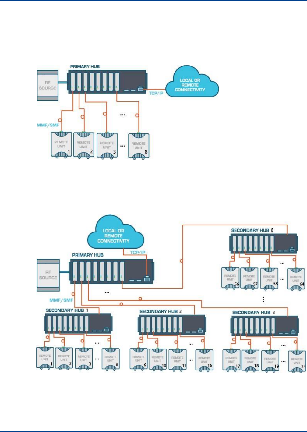
1.3.1. Single Star Configuration
Network Topologies
System Overview
In its single star fiber-to-antenna topology, UNItivity 5000 supports a Primary Hub with up to 8 Remote
Units.
1.3.2. Double Star Configuration
In its double star configuration, UNItivity 5000 supports a single Primary Hub connected to up to 8
Secondary Hubs each supporting 8 Remote Units, bringing the system total to up to 64 Remote Units.
The UNItivity 5000 system can also support a mixed topology, such that Remotes can be directly
connected to the Primary Hub (single star configuration) while also supporting Secondary Hubs
connected to the same Primary Hub (double star configuration). A typical mixed topology use case has
a location
Installation and Configuration 1-5
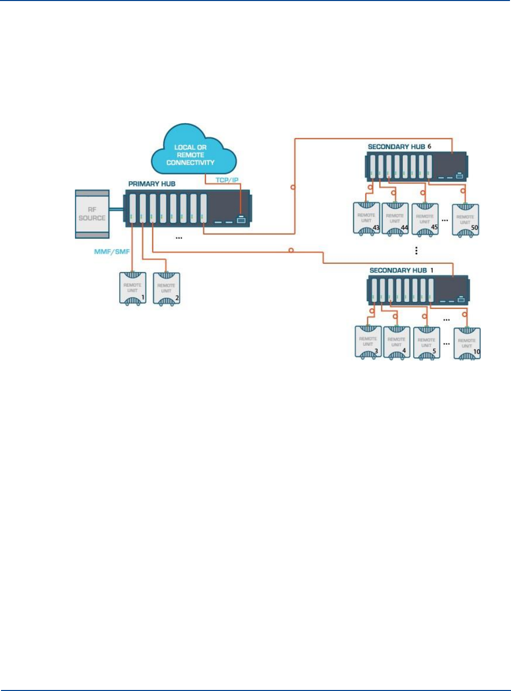
Network Topologies
System Overview
needing coverage that is in close proximity to the Primary Hub, while also needing to support longer
fiber runs or other buildings from that same Primary Hub such that it would be necessary to deploy a
Secondary Hub. In this case, the total number of Remote Units that can be supported from the Primary
Hub is a function of the number of Remotes which are directly connected to the Primary Hub. For
example, if 4 Remote Units were directly connected to the Primary Hub then only 4 Secondary Hubs
could be simultaneously supported, with the resulting maximum total number of Remotes supported off
the Primary equal to 36 (4 directly connected Remotes + 32 Remotes connected via the 4 Secondary
Hubs).
1.3.3. Network Cabling
All cabling is done via optical fiber. The transceivers within the Hubs and Remote Units are intended
for use with 9/125 µm SMF terminated in SC/APC connectors.
Extensive cable lengths can be delivered, using the same core components. This length of
interconnection is more than adequate to facilitate a high quality, broadband, in-building coverage
extension system for multiple, simultaneous wireless feeds for cellular and public safety as well as
anything from 150 MHz to 2700 MHz.
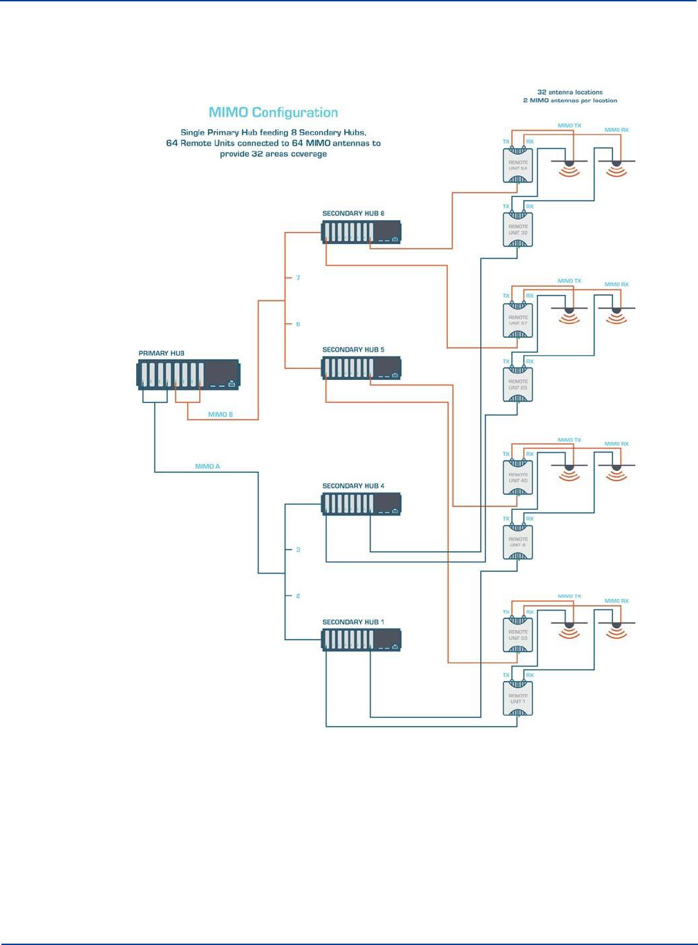
1.3.4. Support For MIMO Services
The next generation of high data-rate services such as LTE provide various multiple-input and
multiple-output (MIMO) options. Where base stations (BTS) are deployed to provide in-building
coverage, these options can be used to increase the overall capacity or coverage of the system.
Typically, BTS signals are distributed inside buildings via a Distributed Antenna Systems (DAS) which
has multiple antenna locations to provide multiple copies of each signal. In the case of MIMO, each
antenna location will require 2 or more independent signals from the same BTS. The standard
UNItivity 5000 single star and double star architectures support a traditional single signal (SISO) BTS.
See “Single Star Configuration” on page 1-5 and “Double Star Configuration” on page 1-5.
1-6 Installation and Configuration

Network Topologies
System Overview
In the case of a single star topology, 8 Remotes would have 16 antennas. For double star at a capacity
of 8 Secondary Hubs, each with 8 Remote Units, you could have 64 Remotes Units with a total of 128
antennas at 64 antenna locations. Each location consists has 1 Rx and 1 Tx antenna.This architecture
has to change to support a dual-transceiver MIMO BTS.
In a full MIMO double star configuration, there would be 1 Primary Hub and 8 Secondary Hubs. Of
these, 4 would be carrying MIMO A and 4 MIMO B. Each Secondary Hub still connects to 8 Remote
Units: however, now 32 of those units have MIMO A and the 32 MIMO B.
If the MIMO installation still uses SISO antennas, the number of antennas remain the same at 128, 64
for MIMO A and 64 for MIMO B. This is because each location now has 2 Remote Units with 2 Tx and
2 Rx antennas. The number of antenna locations is now 64.
Installation and Configuration 1-7
Network Topologies
System Overview
If MIMO antennas (which have 2 RF connections) are used, the number of antennas is 32 for MIMO Tx
and 32 for MIMO Rx. The number of antenna locations is now 32.
Note: The MIMO routing is done via the Signal Routing Matrix in the Primary Hub.
1-8 Installation and Configuration
1.4 Understanding Optional Components
Understanding Optional Components
System Overview
You can enrich the standard UNItivity 5000 solution by incorporating optional components. Optional
components enhance system input capability or the operation of a core component. The POI expands
system RF input capability while the stand-alone PSU provides a simple install power capability for
Remote Units connected directly to the Primary Hub.
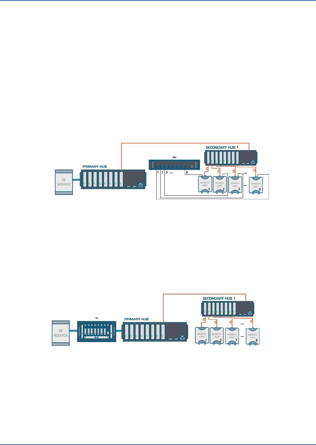
1.4.1. How the PSU Fits in
The Central 48V DC Power Supply is a 1U rack mountable unit that can be used to power Remote
Units directly connected to the Primary Hub. This 600W unit provides eight 48V outputs on terminals
supporting twin core cabling. It would typically be co-located with the Primary Hub, and can be
monitored via a USB port on the Primary Hub. Secondary Hubs incorporate similar Power Supply
functionality as standard.
1.4.2. How the Active POI Fits in
The Active POI provides the interconnection between the RF source (for example, high power sources
like BTS or repeaters where significant attenuation is needed) and the Service Module that is installed
in the Primary Hub. It’s compact design provides multiple passive elements for signal conditioning/
attenuation.
The POI integrates directly to the UNItivity 5000 system and includes overload protection, filtering,
attenuation, and combining/splitting. Reliability is designed in with a single point of connection to BTS
Duplex and a Simplex connection to the Primary Hub.
Installation and Configuration 1-9
Understanding Service Distribution
System Overview
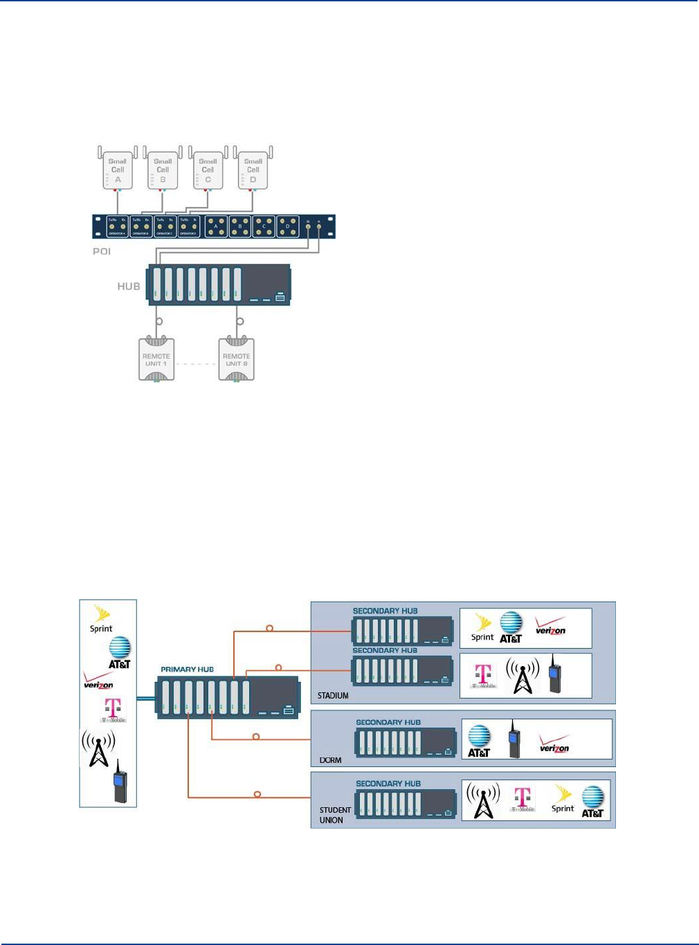
1.4.3. How the Small Cell POI Fits in
Small Cell Point of Interface (SC-POI), provides a low cost, easy to install point of interface panel
enabling quick and easy deployment and integration of up to 4 small cells per panel with Zinwave’s
UNItivity 5000 solution.
1.5 Understanding Service Distribution
UNItivity 5000 supports any service mix, protocol, or modulation scheme from 150MHz to 2700MHz.
That means it can take inputs from a variety of RF source inputs such as wireless and IP data
services from mobile data carriers and base stations. To handle this, UNItivity 5000 uses a software-
defined service distribution matrix. This means specific operators or frequencies can be routed to the
entire system or to designated sections of the system, depending on requirements. The matrix (as
defined by the user) routes various signals from a Primary Hub to Secondary Hubs. The picture below
shows how a variety of inputs can be routed in a campus environment.
1-10
Installation and Configuration
Chapter 2: Understanding the Components
UNItivity 5000 has core and optional components. Core components are all necessary for system
operation. Core components include:
•
Primary Hub
•
Service Module
•
Optical Module
•
Secondary Hub
•
Remote Unit
•
Optical Fiber
•
Configuration GUI (supplied with the Primary Hub)
In addition to the core components, optional components are available to enhance the system’s
capabilities. Regardless of the addition of optional components, a double star topology remains scalable
to 64 Remote Units. Optional components include:
•
Central 48V PSU (1U - 600W)
•
POI (Active and Small Cell)
2.1
Hubs
A UNItivity 5000 system consists of a single Primary Hub at the head-end, and up to 8 connected
Secondary Hubs. Both Hubs have a universal AC power input.
2.1.1. Primary Hub
A Primary Hub provides the interface to the RF sources and converts RF signals to optical. It then
connects via fiber to either Secondary Hubs and/or Remote Units.
The Primary Hub includes at least one Service Module (see “Service Module” on page 2-4). Service
Modules interface with RF sources such as base stations or repeaters. The Hub can be equipped with
up to four Service Modules (installed in the rear) to accept any combination of frequencies between
150MHz-2700MHz, and up to 8 Optical Modules (located at the front, see “Optical Module” on page 2-5)
to connect via optical fiber to Secondary Hubs or Remote Units directly. The Primary Hub supports
single or dual star configurations or a mix of both. The Primary Hub is normally co-located with BTS or
RF source equipment.
2-1
Hub
Understanding the Components
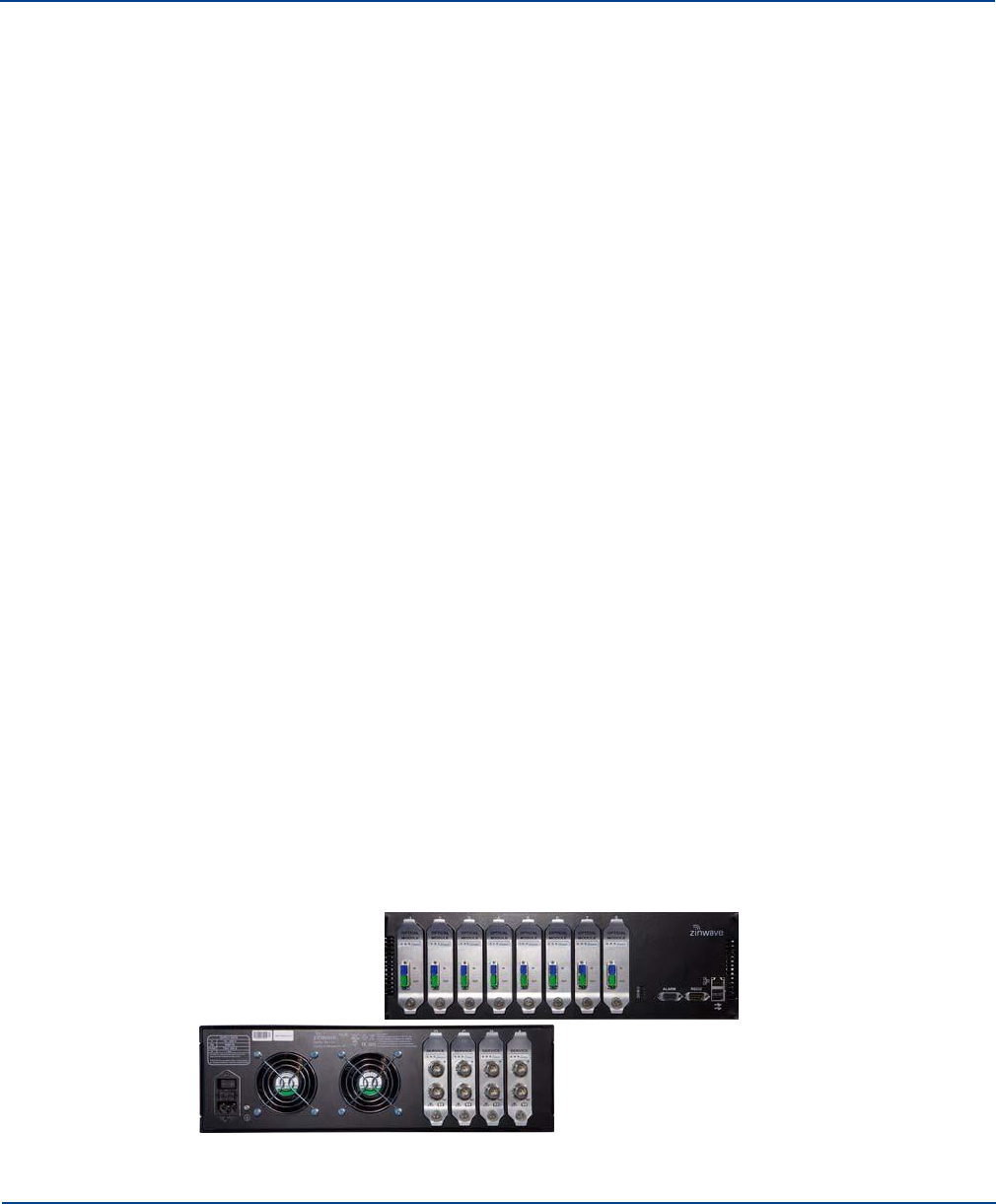
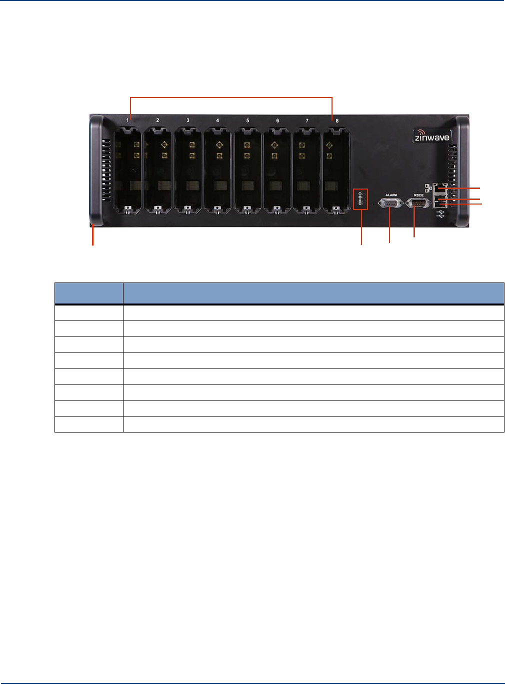
2.1.1.1.
Front View
The Primary Hub may be delivered with up to 8 Optical Modules. See “Optical Module” on page 2-5 for
more information on Optical modules.
1
2
3
4
8 7 6 5
Number
Description
1
Slots1 to 8 for Optical Modules
2
Ethernet connector
3
USB Connector (Type A)
4
USB Connector (Type A)
5
RS232 Connector
6
Alarm Connector (9 way D-type)
7
Status LEDs
8
Handle and Mounting Bracket (both sides of device)
2-2 Installation and Configuration
Hub
Understanding the Components
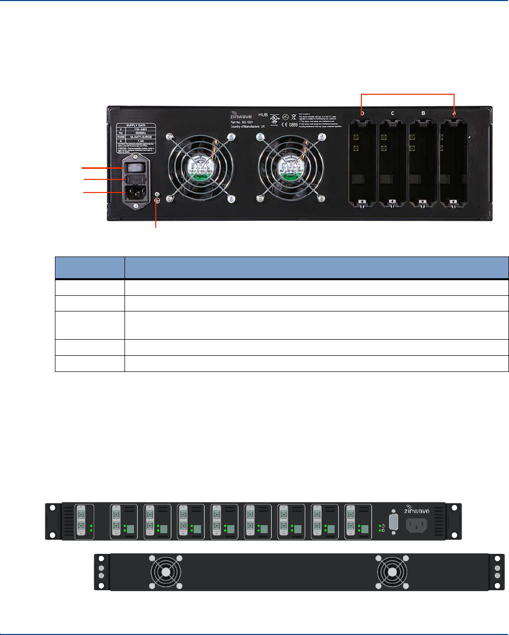
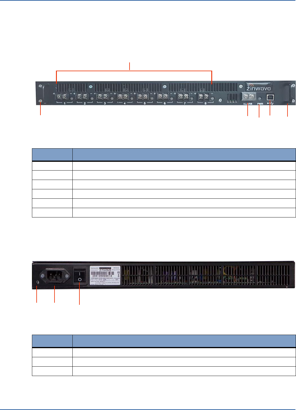
2.1.1.2.
Rear View
The Primary Hub may be delivered with up to 4 Service Modules. See “Service Module” on page 2-4
for more information on Service modules.
1
2
Number
Description
1
Slots A to D (left to right) for Service Modules
2
Grounding Post
3
IEC AC Power Cord Connector shown. For DC power connection callouts and
details see “DC Powered Hub” on page 5-6.
4
Fuse
5
On/Off Power Switch
2.1.2. Secondary Hub
A Secondary Hub receives input via an optical link from a Primary Hub to distribute RF feeds between
the Primary Hub and Remote Units. The Secondary Hub supports fiber connections to up to 8
Remotes as standard. As the Secondary Hub can be located far from the Primary Hub, the deployed
architecture can be tailored to meet and work with building layout and location of appropriate
equipment rooms. The Secondary Hub can be collocated with the Primary Hub or distributed
throughout the site as appropriate.
Installation and Configuration 2-3
5
4
3
Service Module
Understanding the Components
2.1.2.1.
Front View
1 2 3 4 5
Number
Description
1
Duplex SC/APC Optical connection to Primary Hub
2
Duplex SC/APC Optical connection to Remote Unit (8 positions)
3
Phoenix Contact 5.08mm connector: 48V power for Remote Unit (8 positions)
4
Alarm Connector (9 way D-type)
5
IEC AC Power Cord Connector
2.2
Service Module
Service Modules provide the interface to the RF signal source such as BDA, BTS, or small cell. The
modules are hot swappable units, allowing either system maintenance or the addition of operators or
frequencies to be done without disrupting service. Up to 4 Service Modules can be deployed in the
back of a Primary Hub.
2-4 Installation and Configuration
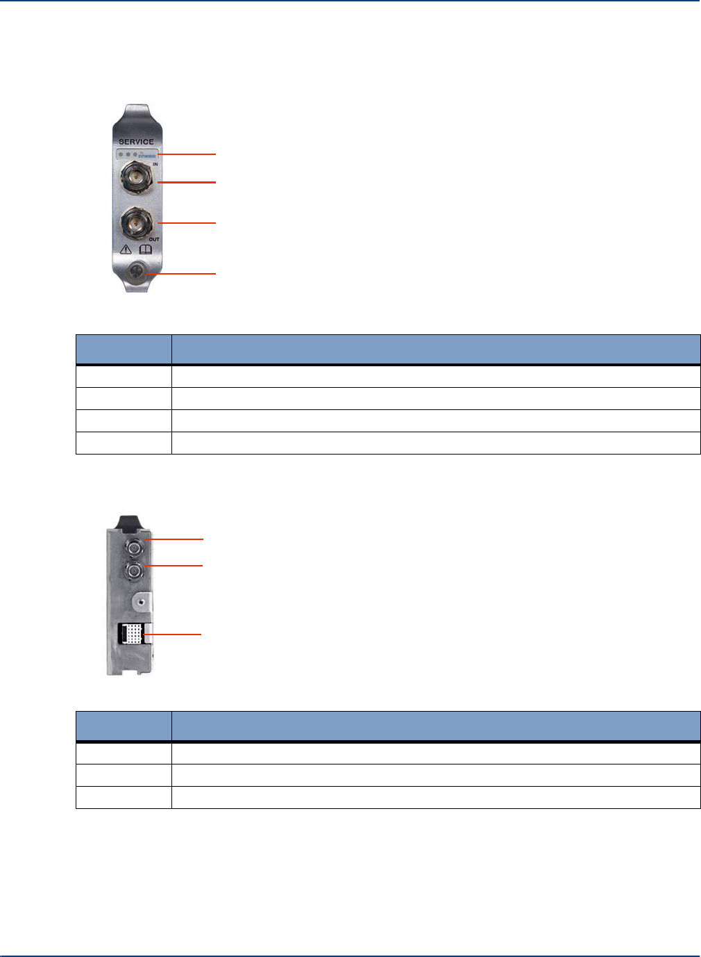
2.2.1. Front View
Optical Module
Understanding the Components
1
2
3
4
Number
Description
1
Status LEDs
2
RF Input N type
3
RF Output N type
4
Retaining Screw
2.2.2. Rear View
1
2
3
Number
Description
1
Floating BMA RF Connector
2
Floating BMA RF Connector
3
Multi-pin Data and Power Connector
2.3 Optical Module
The Optical Module provides the fiber link between a Primary Hub and a Secondary Hub or a Remote
Unit. Up to 8 Optical Modules can be installed in the front of a Primary Hub to connect to Remote
Units or Secondary Hubs as required. These modules are hot
Installation and Configuration 2-5
Optical Module
Understanding the Components
swappable to allow for system maintenance or adding Secondary Hubs or Remote Units with no
impact to service. Optical Modules are intended to connect only by optical fiber.
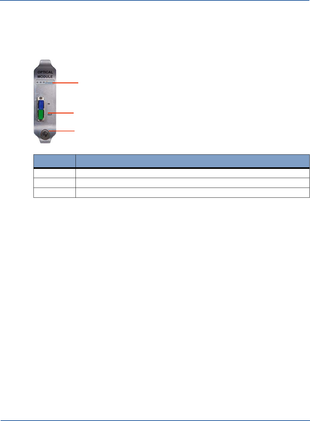
2.3.1. Front View
1
2
3
Number
Description
1
Status LEDs
2
Optical Fiber connector (Duplex SC/APC connector)
3
Retaining Screw
Optical Modules are intended to connect via Zinwave patch cords.
2-6 Installation and Configuration
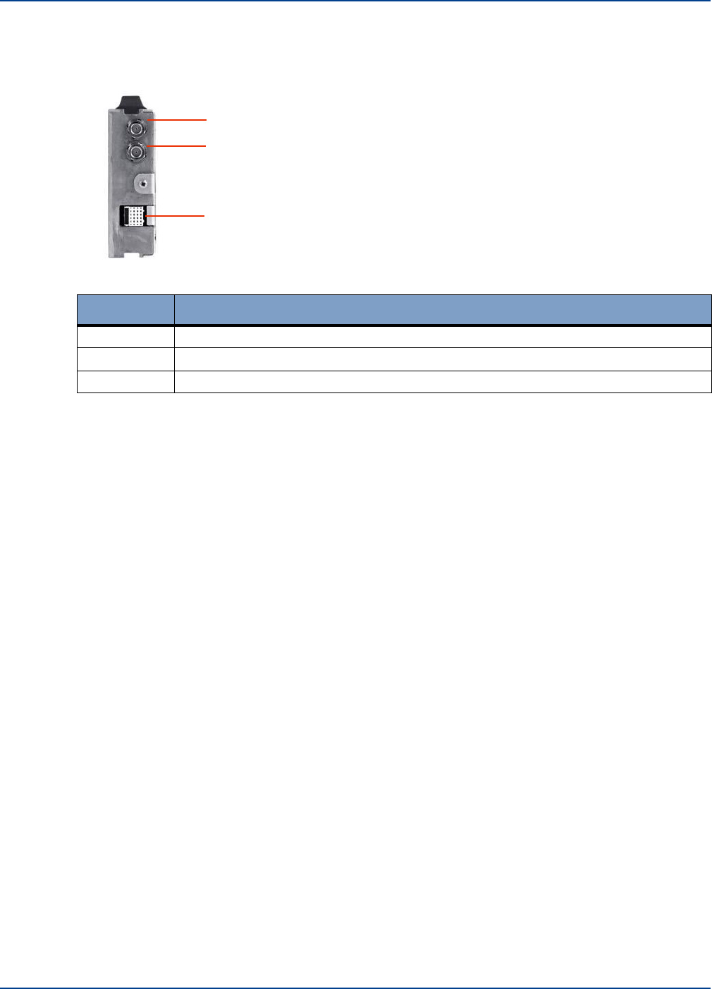
2.3.2. Rear View
Remote Unit
Understanding the Components
1
2
3
Number
Description
1
Floating BMA RF Connector
2
Floating BMA RF Connector
3
Multi pin Data and Power Connector
2.4 Remote Unit
The Remote Unit is a small, wall or ceiling mountable unit that amplifies the received signals for
transmission over a wireless link, in the case of the downlink signals, and amplifies the received
wireless signals for transmission over the optical link, in the case of the uplink signals. It is connected
to the Primary or Secondary Hub via optical fiber. It converts the wireless signal from optical to RF
(and vice-versa) and amplifies it for transmission to or from a mobile device. It defines the final cell
coverage, communicates via optical link to Hubs, and receives and amplifies signals from smart
phones, tablets, laptops, and other hand-held devices.
Installation and Configuration 2-7
Fiber Patch Cords
Understanding the Components
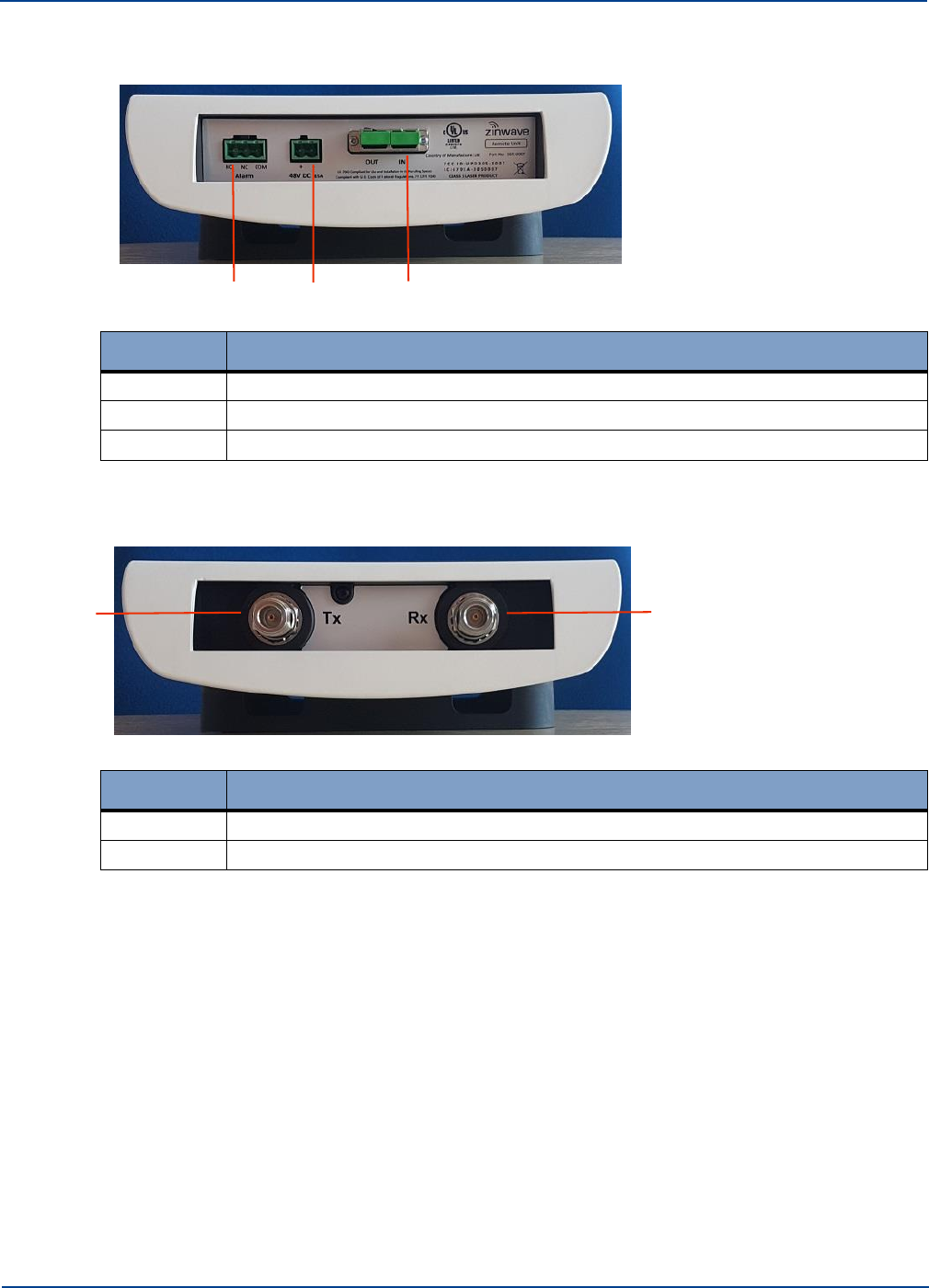
2.4.1. Bottom View
1 2 3
Number
Description
1
Phoenix Contact 5.08mm Connector 3-way: Alarm Relay
2
Phoenix Contact 5.08mm Connector 2-way: 48V DC Input
3
Optical Fiber connector (Duplex SC/APC connector)
2.4.2. Top View
1 2
Number
Description
1
Antenna Connector Receive (Tx) Coax N type
2
Antenna Connector Transmit (Rx) Coax N type
2.4.3. Antennas
A variety of antennas can be connected to the Remote Unit via short coaxial cables.The choice of
antenna will depend on the service requirement within the operational bandwidth of the system. It is
important to ensure that any installed antennas meet the Tx/Rx isolation requirements and that they
are installed in accordance with all relevant safety and exposure regulations. See “Understanding
Antennas” on page 7-1 for detailed antenna information.
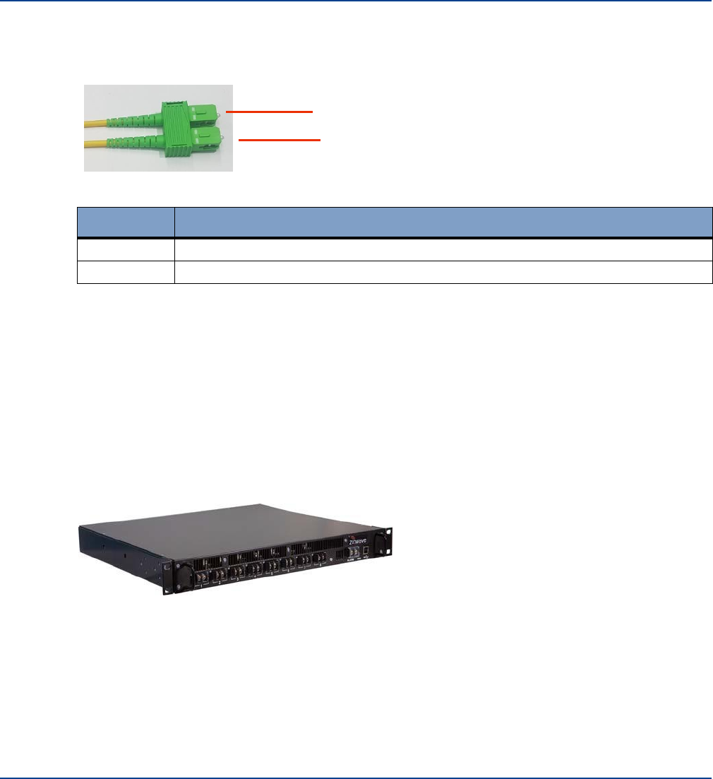
2.5 Fiber Patch Cords
Duplex SC/APC type fiber connectors are used on the Optical Module, Secondary Hub and Remote
Unit. The system uses a laser in the transmit direction and photodiode in the receive direction.
UNItivity 5000 is intended to be deployed with Single-mode fiber infrastructure. Zinwave supplies
various fiber patch cords with the correct duplex SC/APC terminations
2-8 Installation and Configuration
Central 48V PSU (Optional)
Understanding the Components
for the Zinwave UNItivity equipment, and other optical connectors as required to match the
installed infrastructure. The Duplex SC/APC connectivity is shown below:
1
2
Number
Description
1
Out - transmit (laser)
2
In - receive (photodetector)
The TIA 568 color code for connector bodies and/or boots is Beige for Multimode fiber, Blue for
Singlemode UPC fiber connector, and Green for Singlemode APC (angled polished) connectors.
2.6 Central 48V PSU (Optional)
Remote Units connected directly to a Primary Hub may be powered by the Zinwave optional Remote 48V
central power supply unit. Up to 8 Remote Units can be powered by this 600W PSU. The PSU can be
connected to the Primary Hub using a standard USB cable, to enable PSU status monitoring.
1U
Installation and Configuration 2-9

Central 48V PSU (Optional)
Understanding the Components
2-10 Installation and Configuration
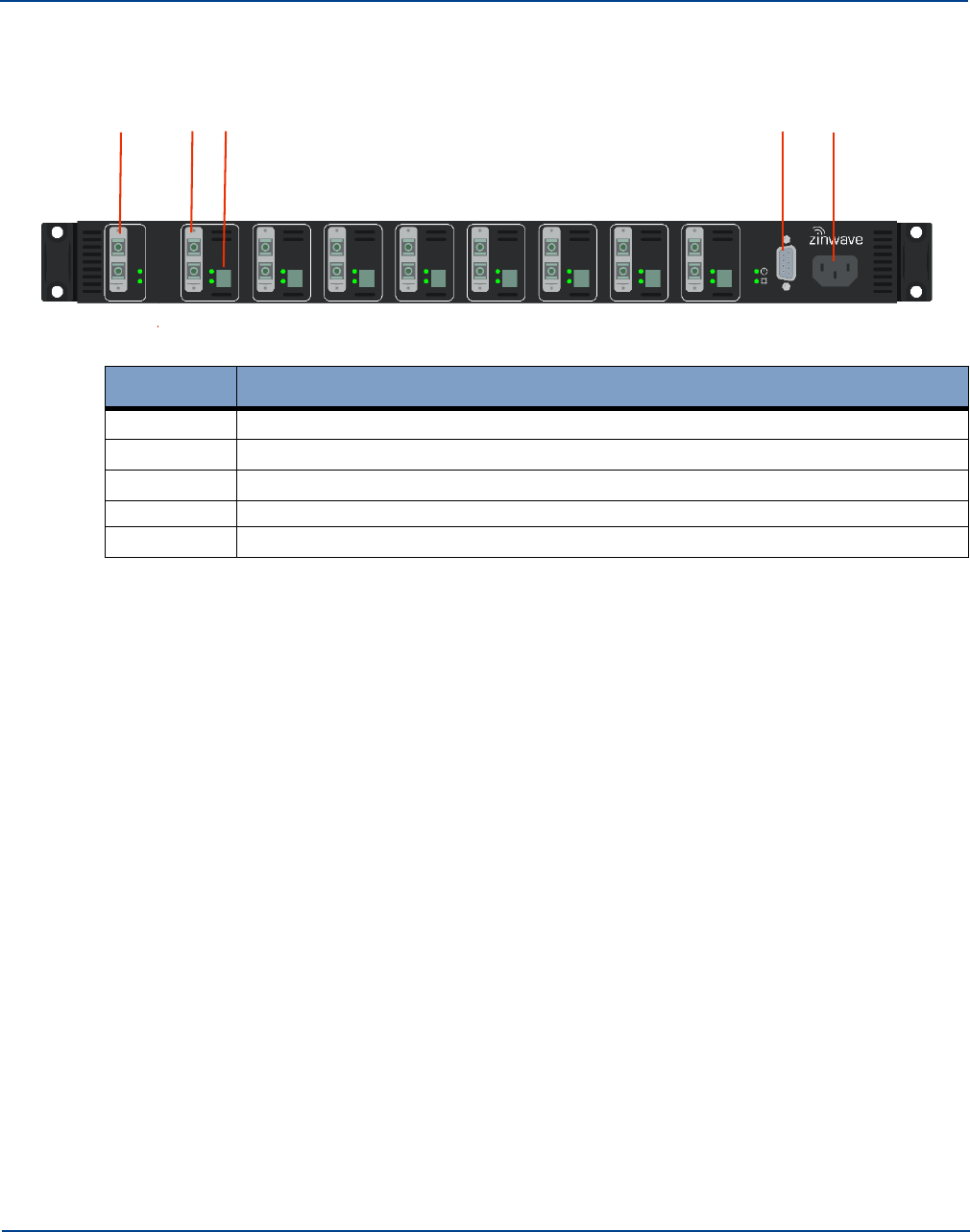
2.6.2. 1U - 600W
2.6.2.1.
Front View 1
Central 48V PSU (Optional)
Understanding the Components
6 5 4 3 2
Number
Description
1
8 Power connector slots with screw terminals (LED for each)
2
Handle
3
USB Connector (Type B)
4
Power LED (indicates power connected to device)
5
Alarm interface - (connect to local fire panel)
6
Mounting Bracket
2.6.2.2.
Rear View
.
1 2 3
Number
Description
1
Grounding Post
2
IEC Power Connector
3
On/Off switch
Installation and Configuration 2-11
POI (Optional)
Understanding the Components
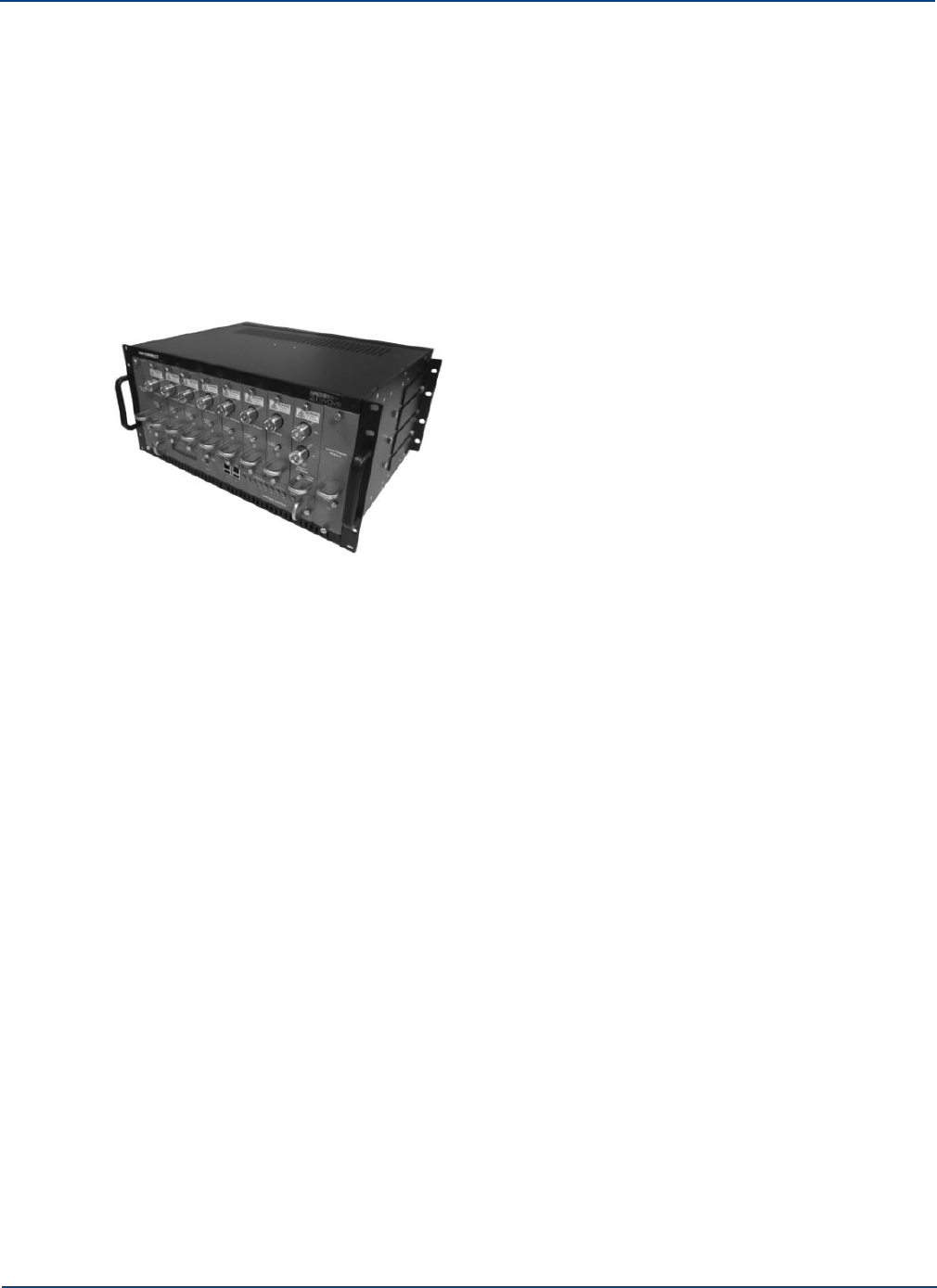
2.7 POI (Optional)
2.7.1. Active POI
The Active POI provides head-end functions (e.g., overload protection, filtering attenuation and
combining/splitting) between the RF sources such as base stations and repeaters and the Service
Module installed in the Primary Hub. You can have two POIs per Primary Hub. The POI consists of a
single 19” rack-mountable chassis containing up to 8 service specific modules that provide the duplex
RF interface to the RF source and the high power attenuation along with 1 or 2 wideband conditioning
modules that provide the active RF control and monitoring functions (variable attenuation, power
monitoring, ALC, overload protection) and a 4-1 combining/splitting function.
See the UNIconnect POI Manual for detailed information about this device, including front and rear
views.
2.7.2. Small Cell POI
The Small Cell POI is a compact single panel (1U) device that integrates up to four small cells for
connection to the UNItivity 5000 system. It can support any frequency from 700MHz – 2700MHz.
The interface is configurable for duplex or simplex operation for each small cell. There are user-
selectable attenuation options, that support the most common Small Cells on the market. No electrical
power is required. This purely a passive connection between the Small Cell and the UNItivity 5000
platform
2-12 Installation and Configuration
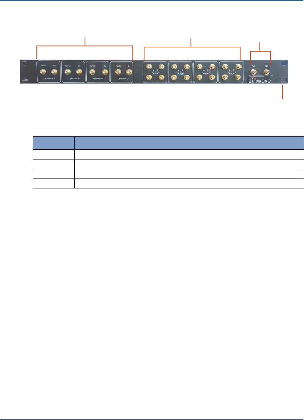
2.7.3. Front View
1
POI (Optional)
Understanding the Components
2 3
4
Number
Description
1
4 pairs SMA connectors each pair Tx/Rx and Rx connections
2
4 sets of 4x SMA – 4x Attenuator selection
3
2x SMA connectors (DL and UL) for interface to Zinwave Hub (service module)
1
Mounting Bracket
There are no connectors on the rear of this device.
Installation and Configuration 2-13
Configuration GUI
Understanding the Components
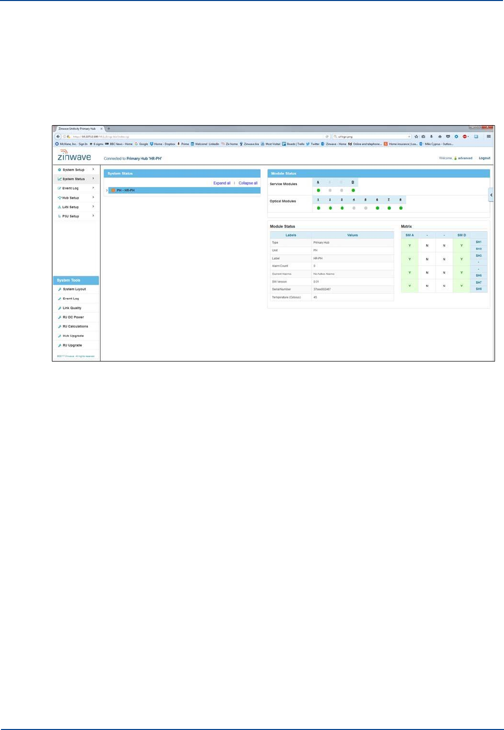
2.8 Configuration GUI
The Configuration GUI is delivered with and resides on the Primary Hub. It provides all the
parameters needed to configure and monitor Primary Hubs, Secondary Hubs, and Remote Units. This
web-based application is accessible via standard browsers and provides SNMP support to integrate
with SNMP monitoring tools for alarm notification.
2-14 Installation and Configuration
Chapter 3: Primary Hub and Module LEDs
3.1
Primary Hub Front Panel LEDs
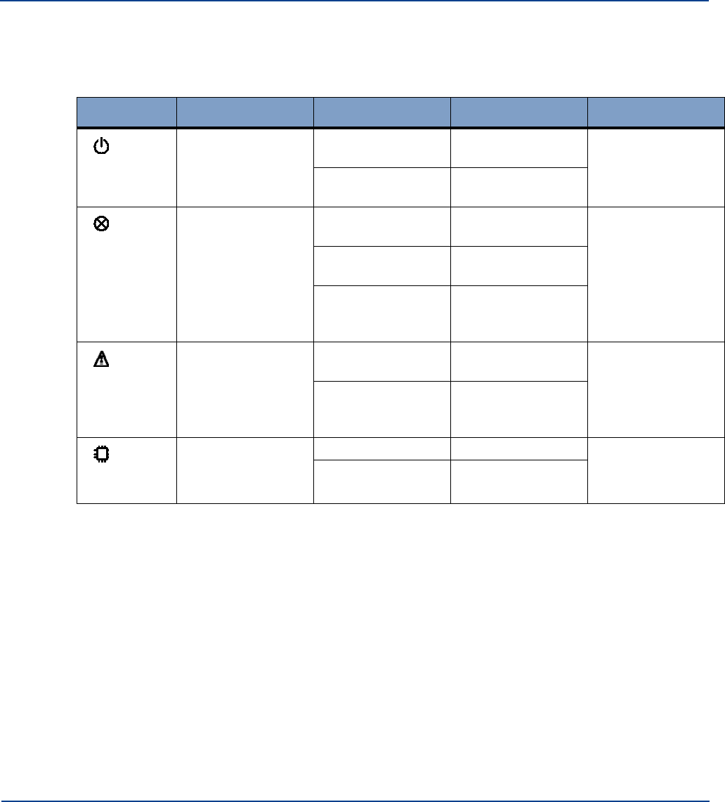
There are four LEDs on the front of the Primary Hub. The following table describes them:
Symbol
Name
Status Color
Description
Comment
Power Indicator
Green
Power connected
to CPU board
Shows processor
is correctly
powered
Off
No power
connected
Service Indications
Green
No error. System is
fully functional
This alarm cannot
be masked and will
ALWAYS be Red
when loss of
service conditions
active.
Red
Loss of service
currently active
Red/Green
Flashing
Firmware
programming in
progress
Warning Indicator
Green
All Units operating
correctly
Orange
Service or
Hardware warning
currently active
CPU Indicator
Green
CPU running
Shows Processor
is correctly
operational
Orange
CPU restarting
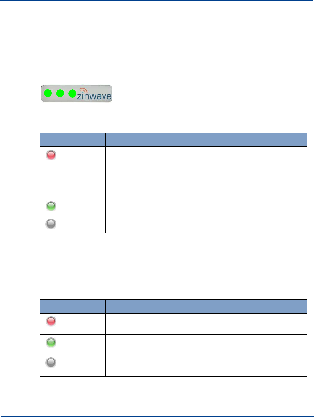
3.2
Service and Optical Module LEDs
There are three LEDs on the front of each module which indicate operational status.
•
The right LED indicates power status.
•
The middle LED indicates communication status between the module and the far end.
•
The left LED indicates the current state of the module.
As part of the auto discovery process the Hub communicates with each module in turn, and cycles
through the installed modules. During this period, the Primary Hub checks for the presence of any
Secondary Hubs and Remote Units. If none are found, the unit cycles to the next module.
For Optical Modules, if no Remote Units are connected, only the right and middle LED’s are operational.
3-1
Service and Optical Module LEDs
Primary Hub and Module LEDs
Initially the right LED will be a dull red, indicating that power is connected but the module is disabled.
This will change to green as the Hub detects the presence of the module. As the unit polls each of the
installed modules, the right LED shows green. The middle LED shows green if the unit has
successfully discovered one or more downstream system elements connected to the Optical Module.
Only when a Remote Unit is detected will the third LED be activated.
A fully functioning module with fully operational downstream elements displays three green LEDs.
3.2.1. Power LED - Right
LED
Color
Description
Dull Red
Initial power-up. Power present on Hub allowing Module
detection to proceed; or
Module NOT Enabled through System Setup; or
Module not inserted in valid Hub slot.
Green
Module in normal operation. Ready for use (Power to
module).
Off
No power to module.
3.2.2. Communications - Middle
Once plugged in, the Optical module attempts to establish communication with the far end.
Service Modules do not communicate with Remote Units or other Hubs; therefore, the
Communications LED is deactivated for Service Modules.
LED
Color
Optical Module Description
Solid Red
No successful communication with any downstream
system elements after initial attempts.
Green
Module in normal operation. Communication established
with at least one downstream system element.
Off
Module is not powered, or has not yet completed initial
attempts to communicate with downstream system
elements.
3-2 Installation and Configuration

3.2.3. Status - Left
Installation and Configuration
Service and Optical Module LEDs
Primary
Hub and Module LEDs
3-3
LED
Color
Service
Module
Optical Module
Off
Normal condition
Module is not powered, or optical calibration and
auto-setup of downstream units not yet started.
Green
Not Used
Optical Module and all downstream system
elements operating normally.
Flashing
Green
Not Used
Optical link calibration and auto-setup of
downstream units in progress; and/or
One or more downstream Remote Units have
their radio transceivers disabled.
Red
Not Used
Optical calibration and auto-setup Error – For
Possible causes refer to “System Status” page
on GUI
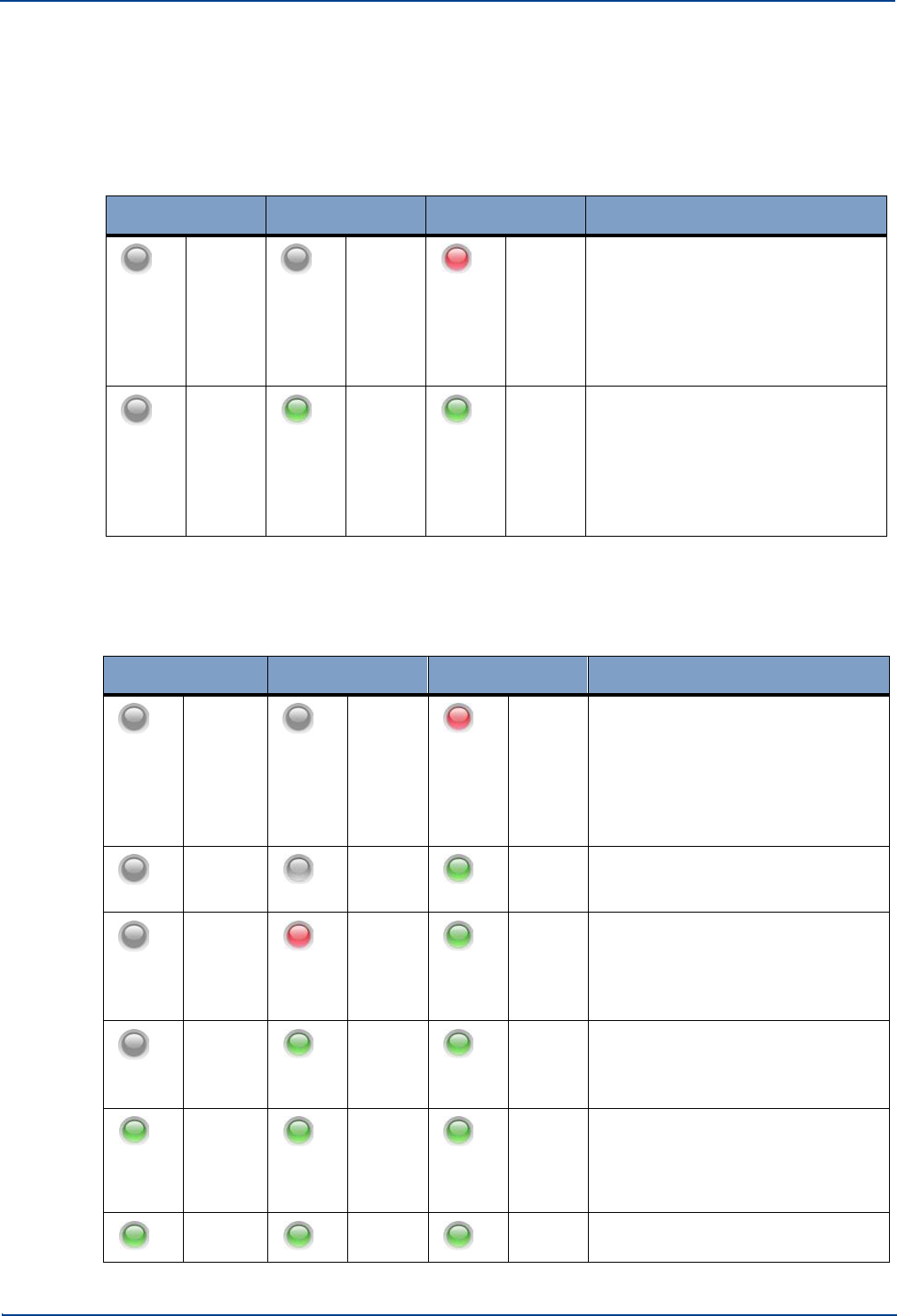
Start-up Sequence
Primary Hub and Module LEDs
3.3 Start-up Sequence
3.3.1. Service Module
The following table shows a typical LED start-up sequence for a fully enabled Service Module:
Left
Middle
Right
Status
Off
Off
Dull
Red
Initial power-up. Power present on
Hub allowing Service Module
detection; or
Service Module NOT Enabled
through System Setup; or
Service Module inserted in invalid
slot. (E.g. In an output (front) slot).
Off
Green
Green
Service Module successfully
detected and in normal operation; or
Service Module with Service
Warning; or
Service Module with Service Loss.
3.3.2. Optical Module
The following table shows a typical LED start up sequence for a fully enabled Optical Module:
Left
Middle
Right
Status
Off
Off
Dull
Red
Initial power-up. Power present on
Hub allowing Optical Module
detection; or
Optical Module NOT Enabled
through System Setup; or
Optical Module inserted in invalid
slot. (E.g. In an input (rear) slot).
Off
Off
Green
Optical Module successfully
detected, starting discovery of
downstream system elements.
Off
Red
Green
Potential communication failure
state: if no downstream system
elements have responded after
a number of communication
attempts (discovery continues).
Off
Green
Green
Communication success state:
communication with at least one
downstream system element
successfully established.
Green
Flash
Green
Green
Optical calibration and auto-setup of
downstream units in progress,
and/or one or more downstream
Remote Units have their radio
transceivers disabled.
Green
Green
Green
Optical Module and all downstream
system elements operating normally.
3-4 Installation and Configuration
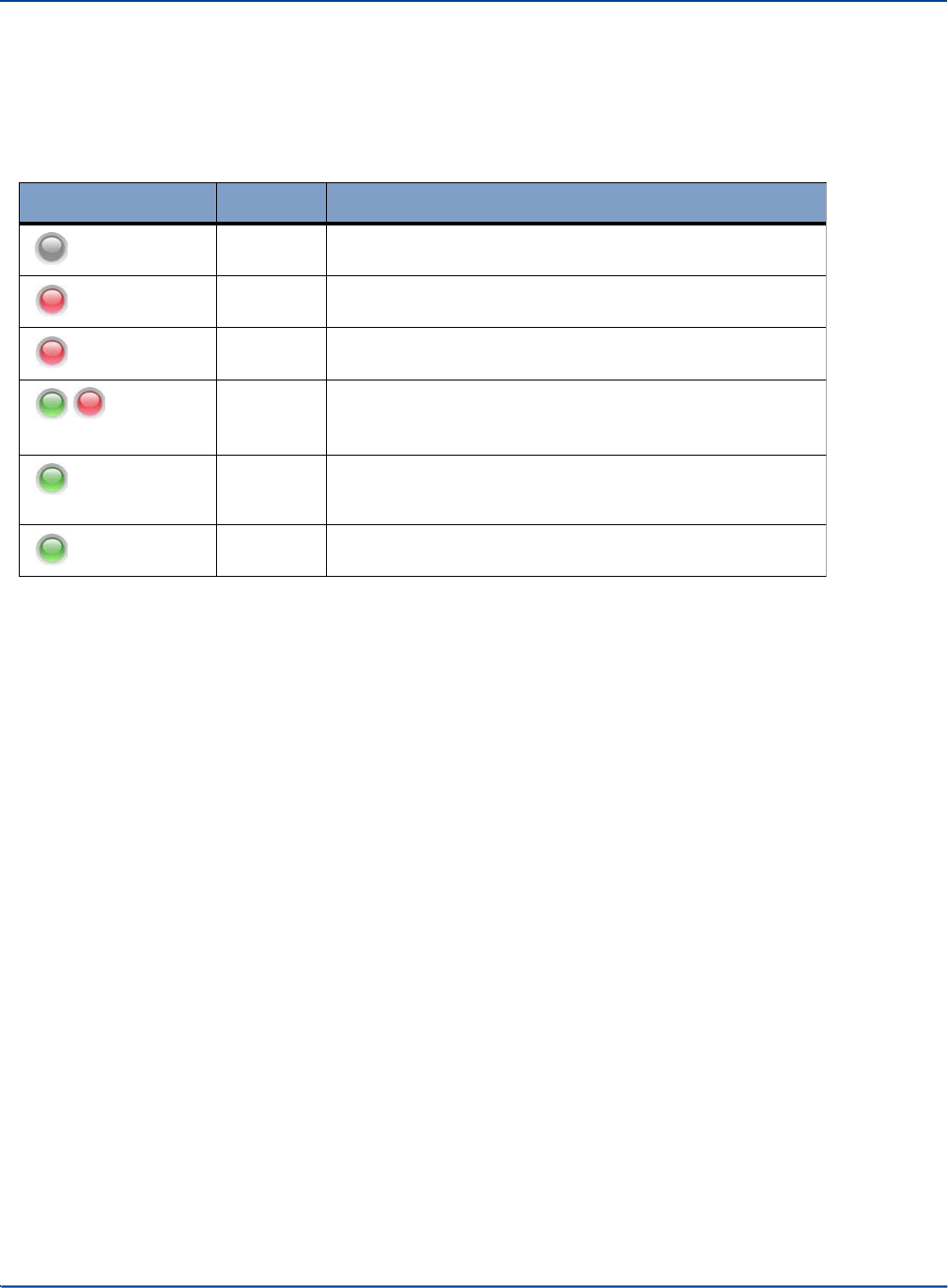
3.4 Remote Unit LEDs
There is a single LED on the Remote Unit visible at the fiber end plate:
Installation and Configuration
Remote Unit LEDs
Primary
Hub and Module LEDs
3-5
LED
Color
Description
Off
No power to Remote Unit
Red
No connection to Hub
Red Flash
Alarm active
Alternate
Red/
Green
Associating with Hub
Green
Flash
Unit successfully associated with Hub.
Optical link calibration and auto-setup in progress, and/or
Remote Unit radio transceiver disabled.
Green
Remote Unit fully operational

Remote Unit LEDs
Primary Hub and Module LEDs
3-6
Installation and Configuration

Chapter 4: Performing a Basic Installation
The following procedure is intended to provide you with a basic work flow to get a new system up and
running. It provides references to specific instruction for that step.
To install UNItivity 5000:
1.
Unpack and verify all components (See section “Installing and Populating Hubs” on page 5-1 for
Hubs).
2.
Rack mount Hubs and populate with the appropriate modules (See section “Installing and Populating
Hubs” on page 5-1).
3.
Install Remote Units and antennas (See section “Installing Remote Units” on page 6-1 and
“Connecting Antenna to Remote Units” on page 7-4).
4.
Install power for Remote Units (local or PSU) (See section “Powering Remote Unit” on page 6-3).
5.
Make and check all connections for power and data between Primary, Secondary, and Remote
Units. This will be fiber for Optical Connections. (See section “Infrastructure and Cabling” on page
8-1).
6.
Ground any Rack Mounted Equipment. See “Grounding Rack Mounted Equipment” on page 9-5.
7.
Power on all equipment (See sections “Powering the Hub” on page 5-5 Hub and “Powering Remote
Unit” on page 6-3 for Remote Units).
8.
Watch LEDs for self-test and connection. (See section “Start-up Sequence” on page 3-4). Trouble
shoot connections on infrastructure cables using LEDs (see “Hub and Hub Module LEDs” on page 3-
1). Swap fibers and check power as needed.
9.
Connect the PC to the Primary Hub to configure system. (See section “Initial Stand-alone Access” on
page 11-1).
10.
Access the GUI and view status pages (See section “Accessing the GUI” on page 11-1) and check
firmware (See “Update Firmware” on page 12-1) for each Hub.
11.
Set up the system based on the coverage tool and measured inputs. (See section “Understanding
System Setup” on page 14-1).
4-1

Performing a Basic Installation
4-2 Installation and Configuration
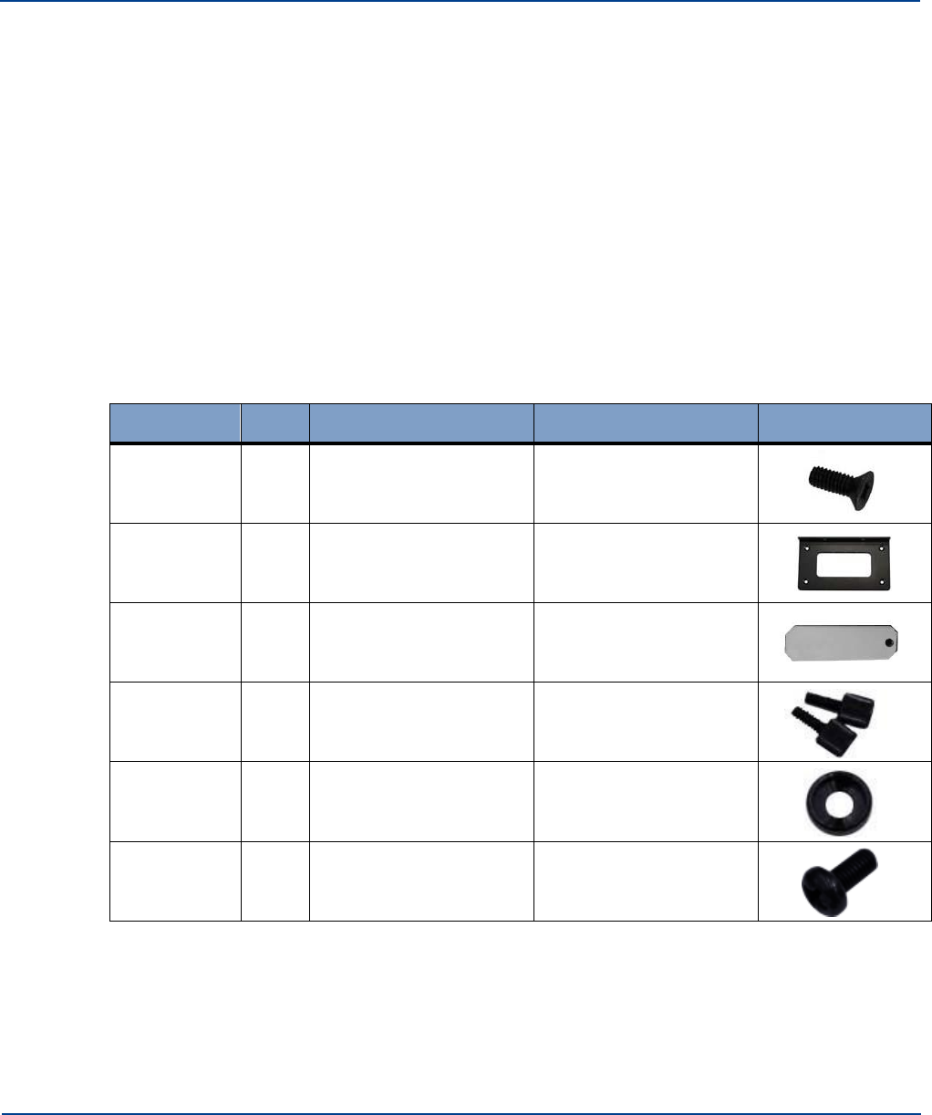
Chapter 5: Installing and Populating Hubs
This chapter describes how to install insert modules into Primary and Secondary Hubs.
5.1
Installing the Hub
You can mount a Primary or Secondary Hub in a standard 19" rack or an open frame rack. There are
many 19" rack systems available on the market of various depths. It is essential that the weight of the
Hub is supported at the front. If the Hub is not adequately supported in your rack, you must provide
support items, such as front-to-rear chassis runners (rails) or fully supported shelves. This manual
provides instructions to mount a Hub in a rack using the only items supplied in the mounting kit.
5.1.1. Mounting Kit
Each Hub is delivered with an accessory box of parts used for rack mounting. This box contains the
following parts:
Part Number
Qty
Detail
Function
Image
128-0118
8
Screw M4 X 10 CSK
POZI STL BLACK
Mounting Bracket Screw
142-0257-01
2
RACK MOUNTING
BRACKET
Mounting bracket for
rack
142-0048-05
12
3000 HUB MODULE
BLANK PLATE
Blanking plates for
unused slots
128-0043
12
SCREW THUMB 6-
32X8MM PC CASE
Retaining Screws
128-0113
4
M6 CUP WASHER
BLACK
Mounting Bracket
washers
128-0112
4
SCREW M6x12 PAN
POZI STL BLACK
Hub Mounting Screws
(suitable for M6 Cage
nuts, not supplied)
5-1
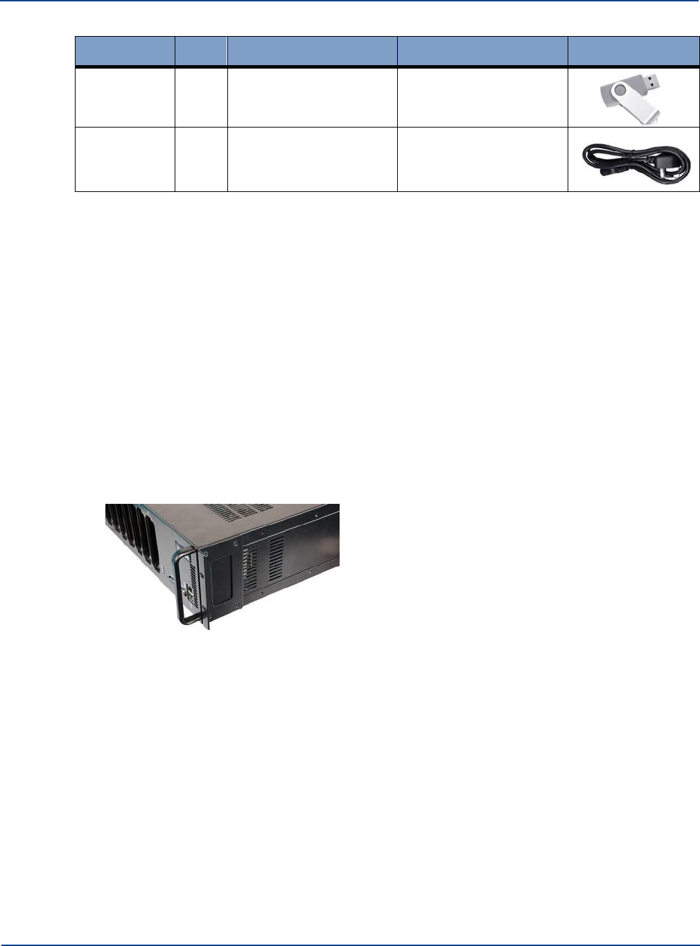
Installing the Hub
Installing and Populating Hubs
Part Number
Qty
Detail
Function
Image
507-0003-02
1
EMS USB
Contains latest Hub
software for
1
Power Cord
Country specific power
cord
5.1.2. Standard 19" Rack Mounting
The Primary Hub is deigned to mount directly into a 19 inch rack framework with no additional
mounting materials.
The following tools are required for installation (Not provided):
•
4x M6 cage nuts appropriate for 19 inch rack frame
•
Pozi-drive screwdriver
•
Cage nut insertion/extraction tool
Note: If rack frame does not use M6 nuts, you must supply appropriate nuts to secure the Hub.
To install the Primary Hub in a rack:
1.
Remove all parts from the Accessory Box included in the box with the Primary Hub.
2.
Attach the mounting brackets (using the black countersunk screws 128-0118) to the side of the
Primary Hub so that the mounting face is flush with the front of the Hub.
3.
Using the cage/nut insert/extraction tool, install 2 M6 cage nuts on each side of the rack. The
spacing must align with the holes in the Hub.
4.
Place the Primary Hub into the rack and secure using screws 128-0112 and washers 128-0113.
5.1.3. Open Frame Rack Mounting
The Primary Hub is designed to mount into an open frame rack with an offset of either 75mm or
125mm (approx. 3 or 5 inches), using supplied mounting materials.
The following tools are required for installation (Not provided):
•
4x M6 cage nuts appropriate for 19 inch rack frame
•
Pozi-drive screwdriver
•
Washers and Screws, suitable for Rack type, to secure equipment
5-2
Installation and Configuration
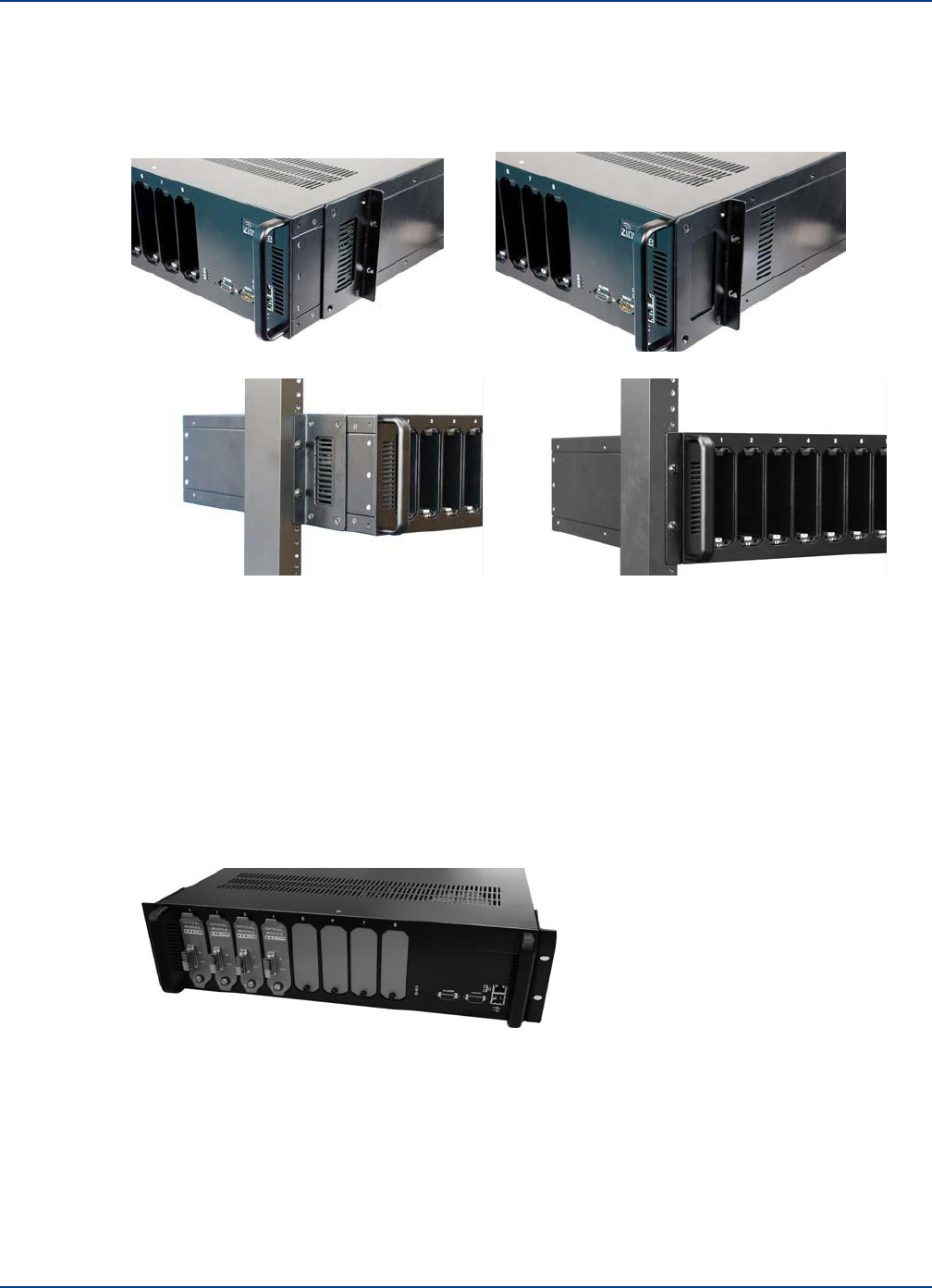
Installing the Hub
Installing and Populating Hubs
To install the Primary Hub in a rack:
1.
Remove all parts from the Accessory Box included in the box with the Hub.
2.
Attach the mounting brackets (using the black countersunk screws 128-0118) to the side of the
Hub in the correct position for the rack.
3.
Place the Primary Hub into the rack and secure using suitable Hub mounting screws and washers.
5.1.4. Installing Blank Panels
Blank panels are available to cover unused slots on a Primary Hub.
To install blank panels:
1.
Place a blank panel over a slot that will not be used and align so that plate hole fits over screw hole
at bottom.
Slots are read by the unit in order in the back from A to D or in the front from 1 to 8. place blank
panels on slot numbers after the amount of intended slots are used. For example, if you are using
slots 1-4, place blank plates on slots 5 to 8.
2.
Insert a retaining screw in the hole and turn to hand-tighten.
Installation and Configuration 5-3

Installing Service Modules (Primary only)
Installing and Populating Hubs
5.2
Installing Service Modules in Primary Hub
Service Modules are inserted in the back of a Primary Hub in slots A to D. See “Primary Hub” on page
2-1 for slot descriptions.
Caution: Optical Module must ONLY be installed on the front panel of a Primary Hub or the
unit will not function as expected.
To install Service Modules in the back of a Primary Hub:
Note: If you are adding or updating modules, remove any blanking plates in the rear slots you wish to
populate by turning the retaining screw and pulling on the top and bottom of the plate.
1.
Visually align the module with the rear slot (screw hole should be on bottom) and insert with your
thumbs at the top and bottom of the front of the module.
2.
Press the module slightly, until you feel it set against the back of the slot.
Modules are equipped with floating BMA connectors in the back that are slightly sprung to
enhance connectivity.
3.
Insert a Retaining Screw and hand-tighten.
A tightened screw ensures best performance. Performance may degrade if screws are not
properly in place.
If power is applied before insertion, see “Primary Hub and Module LEDs” on page 3-1 for LED
descriptions.
Note: LEDs will only fully function when equipment on the other end of the fiber is present and
working
5.3
Installing Optical Modules in Primary Hub
Optical Modules are inserted in the front of Primary Hubs. To install Optical Modules:
Note: If you are adding or updating modules, remove any blanking plates in the rear slots you wish to
populate by turning the retaining screw and pulling on the top and bottom of the plate.
1.
Visually align the module with the rear slot (screw hole should be on bottom) and insert with your
thumbs at the top and bottom of the front of the module.
2.
Press the module slightly, until you feel it set against the back of the slot.
Modules are equipped with floating BMA connectors in the back that are slightly sprung to
enhance connectivity.
3.
Insert a Retaining Screw and hand-tighten.
A tightened screw ensures best performance. Performance may degrade if screws are not
properly in place.
If power is applied before insertion, see “Hub and Hub Module LEDs” on page 3-1 for LED
descriptions.
Note: LEDs will only fully function when equipment on the other end of the fiber is present and
working
5-4 Installation and Configuration

5.4
Powering the Primary Hub
Powering the Hub
Installing and Populating Hubs
The Primary Hub has an IEC AC power socket. The cord purchased is country specific.
To Power on the Primary Hub:
1.
Make sure the On/Off switch is in the Off (O) position.
2.
Plug in the supplied AC power cord the Hub and into an AC power outlet.
3.
Move the ON/OFF switch to the On (I) position.
4.
Verify LED status shows correct start up sequence and the equipment is ready for operation. See
“Start-up Sequence” on page 3-4.
Note if powered up with no modules installed the Primary Hub shows 4 green LEDs. If modules are
installed then the alarm warning and fault LEDs may show alarm conditions at initial start-up. This
could be due to the fact that no Remote Unit elements are connected. These alarms can be cleared via
the Primary Hub Set Up page of the Configuration GUI once the system is correctly configured.
Although modules may be hot swapped, during initial installation it is recommended that the
Primary Hub power is switched off until the initial module installation is completed.
Installation and Configuration 5-5

Powering the Hub
Installing and Populating Hubs
5-6 Installation and Configuration

Chapter 6: Installing Remote Units
This chapter describes how to install the Remote Units along with their power options.
6.1
Mounting Remote Units
Your system installation plan provides the locations to mount each Remote Unit and their associated
antennas. Depending on the available wall space a Remote Unit can be mounted vertically (with antenna
connector closest to ceiling) or horizontally (with antenna connectors facing a side wall).
Remote Units are suitable for use in environmental air space in accordance with Section 300-22(c) of the
National Electrical Code, and Sections 2-128, 12-010(3) and 12-100 of the Canadian Electrical Code,
Part 1, CSA C22.1.
Tools:
•
Drill with M4 bit
•
Pencil
•
M4 Screw driver
Supplied equipment:
•
Remote Unit
•
Zinwave Patch Cords
•
Mounting Bracket
•
4x M4 screws
•
RAWL Plugs
Considerations before Mounting:
6-1
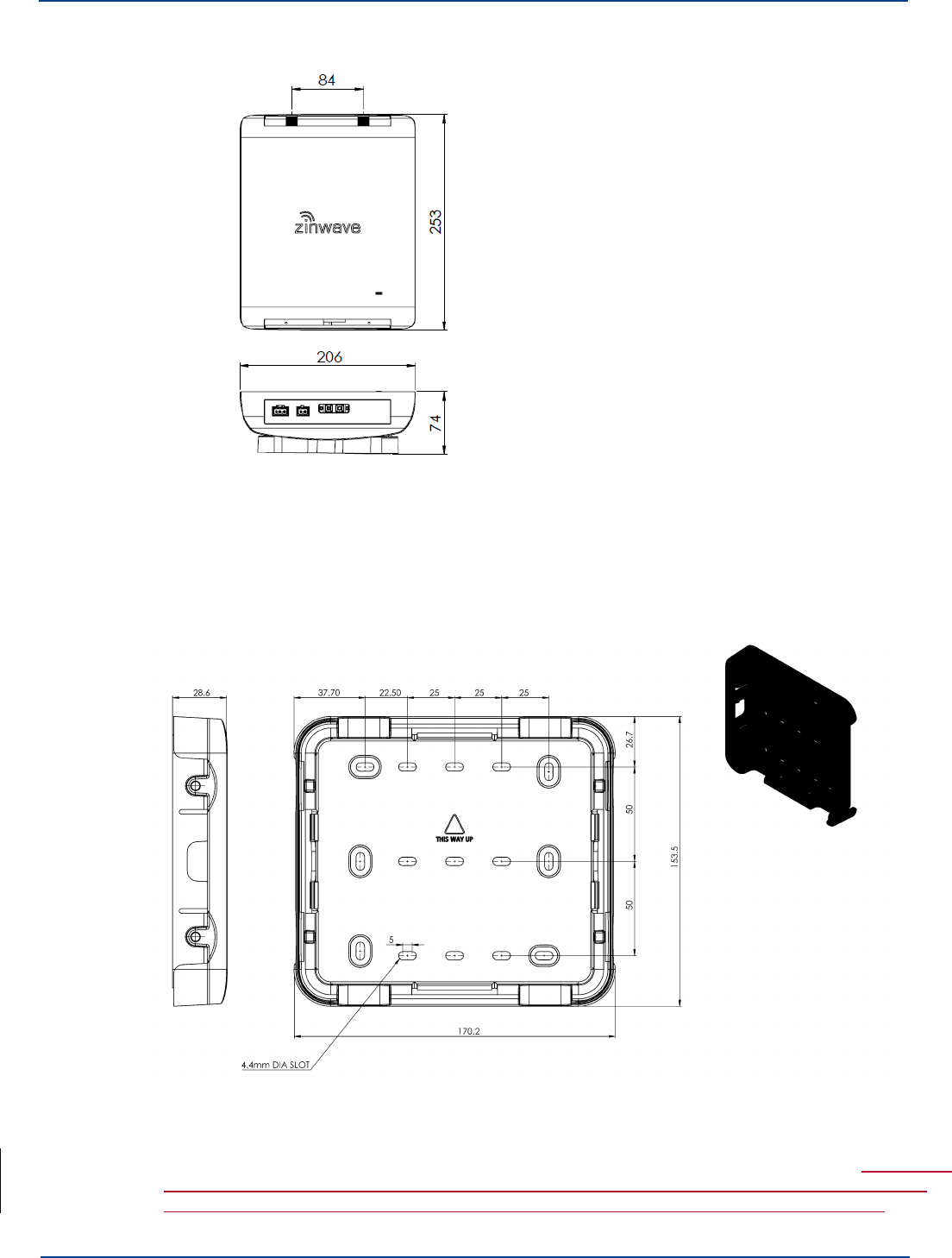
Mounting Remote Units
Installing Remote Units
•
The Remote Unit (with mounting bracket) has the following dimensions displayed in millimeters:
•
Ensure that adequate space is provided to allow for any power and signal cables to be
connected and that minimum bend radii of cables are met.
•
Make sure there is room for antenna connections to exit through the ceiling.
•
Make sure there is adequate clearance around the Remote Unit to allow some convection.
The following wall bracket is provided for mounting a Remote Unit:
1.
Place the mounting bracket on the wall in the desired location and position (Horizontal or
Vertical).
2.
Select 4 suitable screw holes for attachment, and mark the 4 holes to be used with a pencil. The holes
selected should be sufficiently separated. Use one of the 2 hole patterns shown below, or a pattern
derived from one of these 2 patterns where each screw may be moved to an adjacent position.
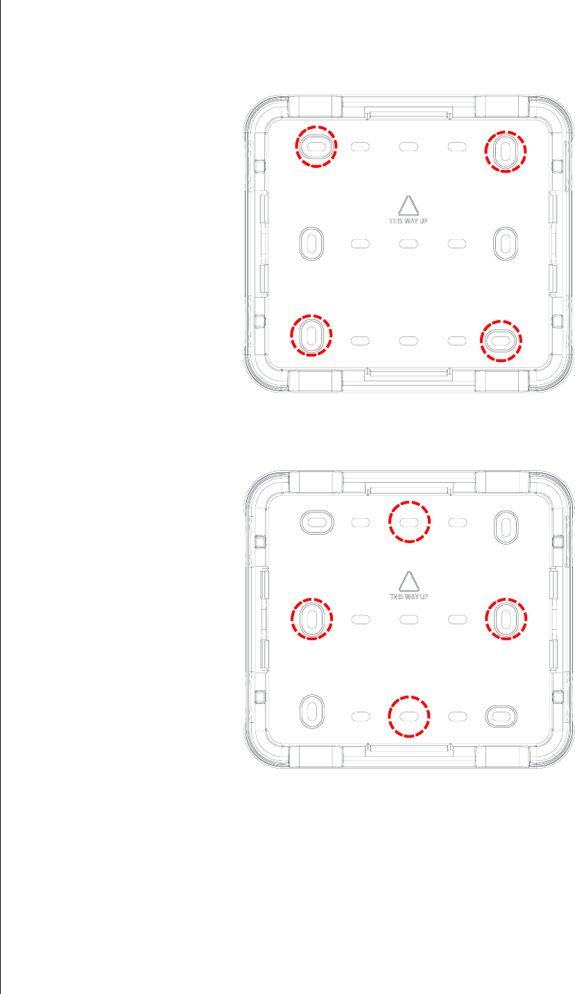
6-2 Installation and Configuration

Powering Remote Unit
Installing Remote Units
3.
Remove the bracket.
4.
Drill the 4 screw holes.
5.
Attach the bracket to the wall using the a M4 screw driver and the 4x M4 screws.
You may need to use additional hardware such as rawl plugs, for a secure fit.
6.
Ensure the 4 M3 locking bolts are in place on the wall bracket, but not screwed in so far as to
protrude into the inner cavity of the wall bracket and prevent the mounting bracket on the Remote
Unit from being inserted.
7.
Align the plastic mounting bracket attached to the back of the Remote Unit with the wall bracket, and
‘plug in’ the Remote Unit. The plastic latches should clip in and hold the Remote Unit in place. If the
Remote Unit needs to be removed, then hold the Remote Unit on both sides with fingers reaching
behind to press the central release buttons on the mounting bracket, allowing the Remote Unit to be
‘unplugged’.
8.
Once the Remote Unit is ‘plugged in’, then tighten the 2 M3 locking bolts on each side with a
screwdriver to ensure the Remote Unit cannot become detached from the wall mounting. This step
is particularly important if the Remote Unit is suspended from the wall bracket and might cause a
hazard if it were to become detached.
6.2
Powering Remote Unit
A Remote Unit receives power from a 48V Central PSU (if connected directly to a Primary Hub), or
from the Secondary Hub to which it is connected.
6.2.1. PSU DC Power
6.2.2.1.
Rack Mount the PSU
The following tools are required for installation (Not provided):
•
4x M6 cage nuts appropriate for 19 inch rack frame (If required)
•
M6 pozi-drive screwdriver
•
Cage nut insertion/extraction tool
•
Washers and Screws, suitable for Rack type, to secure equipment
To install the PSU in a rack:
1.
Using the cage/nut insert/extraction tool, install 2 cage nuts on each side of the rack. The spacing
needs to align with the holes in the PSU.
2.
Place the PSU into the rack and secure using suitable mounting screws and washers.
Installation and Configuration 6-3

Powering Remote Unit
Installing Remote Units
Note: While a power lead is not supplied inside the box as shipped – Zinwave does provide the
country specific power lead in with the shipment where PSU are required by the customer.
6.2.2.2.
Applying DC power to the Remote Unit
See “Connecting the PSU to Remote Units” on page 9-2 for pin out information and “Power
Distribution Requirements” on page 9-2 for power distribution information.
To connect the PSU to the Remote Unit.
3.
Plug the cable into the appropriate connector on the PSU or Secondary Hub.
4.
Route the cable from the PSU to the Remote Unit.
5.
Plug the cable into the 48V connector on the Remote Unit.
6.
Repeat for each PSU / Secondary Hub to Remote Unit connection. Once power
is plugged in, the unit is powered on.
Note: It is recommended to connect fiber prior to powering on the Remote Unit.
6-4 Installation and Configuration
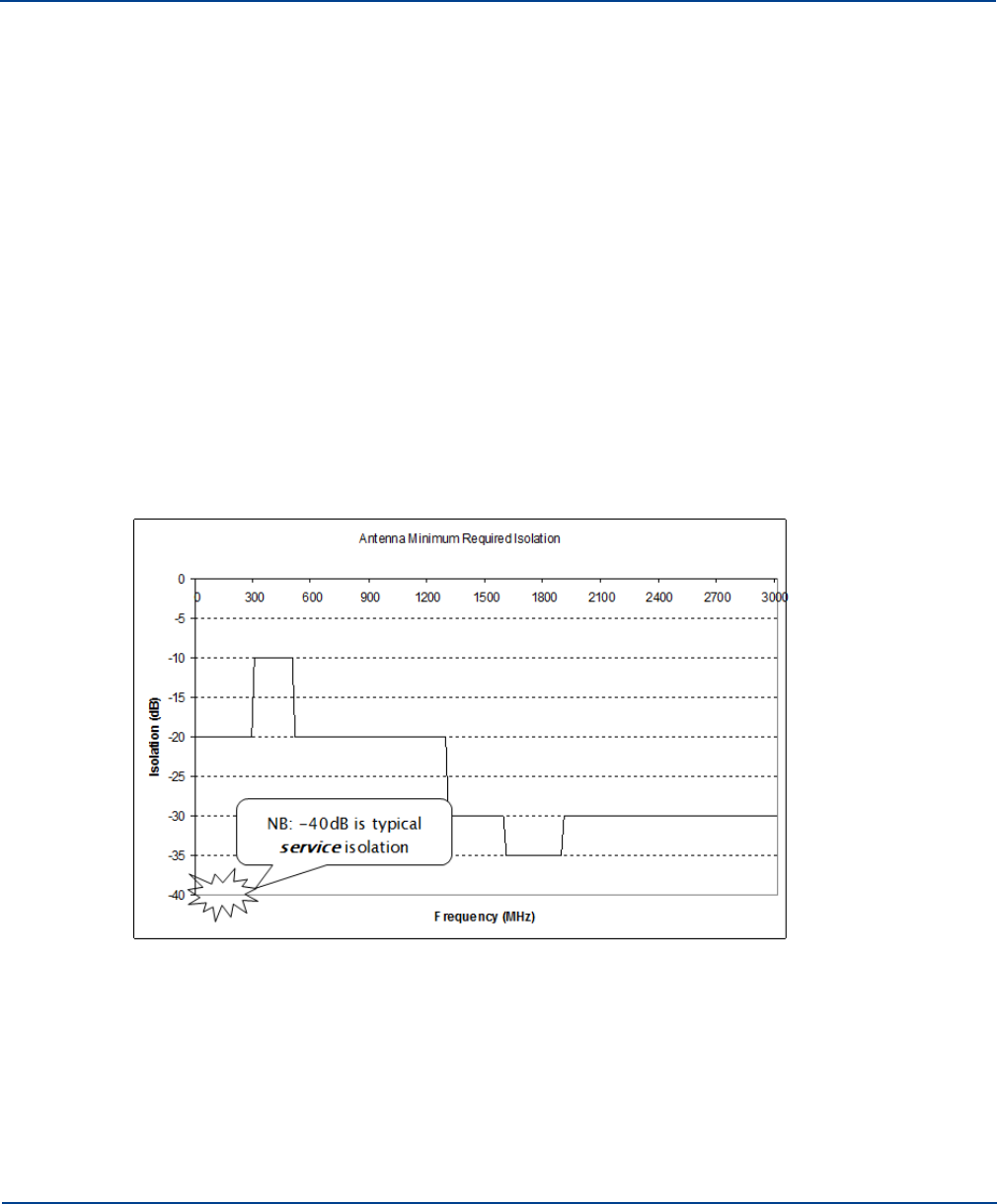
Chapter 7: Understanding Antennas
This chapter describes antenna requirements and how to install Antennas.
7.1
Antenna Requirements
This section describes antennas that can be connected to Remote Units. For physical connection of the
antenna to the Remote Units see “Connecting Antenna to Remote Units” on page 7-4.
7.1.1. Isolation
The minimum isolation between Tx and Rx required for correct operation of UNItivity 5000 in both the
uplink and downlink service bands is usually 40dB (this requirement should be confirmed for any given
installation within the Zinwave Coverage Tool). However, performance (uplink noise and downlink inter-
mode interference) of the system can be improved if greater isolation is achieved. Isolation between the
antennas is achieved by separating them at a sufficient distance to achieve at least 40dB at the lowest
frequency service in use.
In addition to the 40dB service isolation described above, a minimum isolation must be achieved within
the entire UNItivity 5000 passband according to the graph below:
It has been found empirically that omni-directional antennas supporting the Cellular bands from 700MHz
and above require a horizontal separation distance of approximately 20 ft (6m). An example of the isolation
7-1
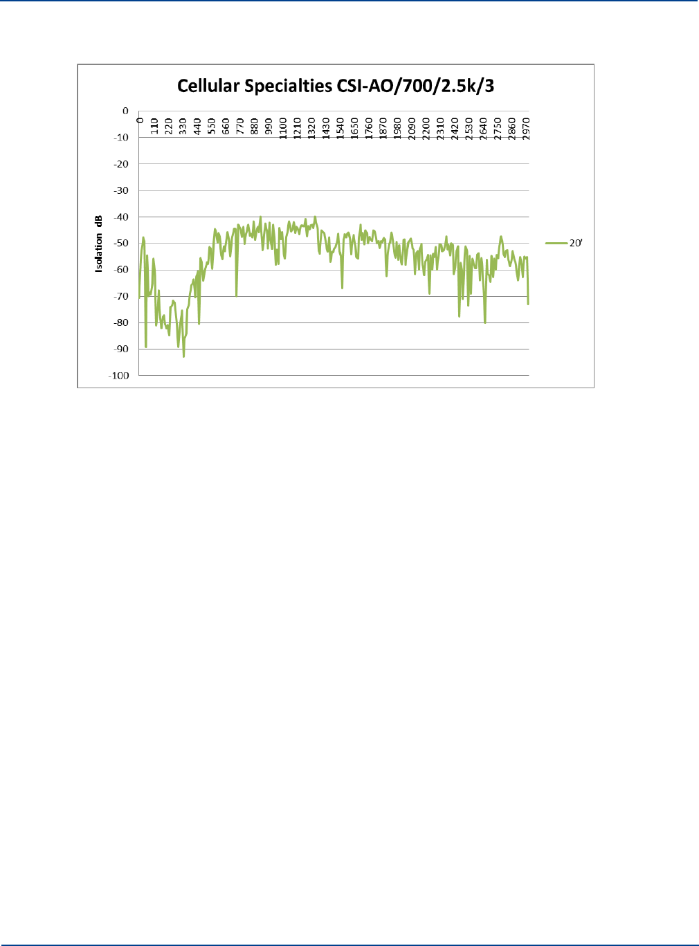
Antenna Requirements
Understanding Antennas
that can be achieved using a wideband (LTE, CELL, PCS, AWS) antenna is shown below:
It can be seen that the isolation improves with frequency due to the increasing propagation loss so that
the PCS and AWS bands have isolation in excess of 45dB when the CELL band is below 40dB.
Although this distance provides a rule of thumb for initial planning, the particular antennas in use and
the environment in which they are installed will affect the isolation. It is recommended to check and
measure the isolation of each antenna pair (see isolation measurement section below) prior to
enabling service operation.
With directional antennas care should also be taken to ensure the high-gain propagation direction is
oriented towards the coverage area and the low-gain (“null”) propagation direction is oriented towards
the second antenna. The effect of this null will be to reduce the distance between the antennas
required to achieve the 40dB isolation.
7.1.2. Isolation Measurement Techniques
The most accurate way of measuring the antenna isolation, is to disconnect the cables at the Remote
Unit antenna ports and connect these directly to either a network analyzer or a spectrum analyzer with
a tracking generator. Every antenna in the installation should meet the requirements of the Tx-Rx
Isolation section above.
Where many antennas within an installation are being checked it is recommended to enter a test mask
in the test equipment.
Where it is not possible to access all antennas in this way, it is possible to check the isolation using
measurements at the Hub. However, in this case the gain profile of the uplink and downlink paths must
be removed from the measured values in order to reveal the actual antenna isolation. It is
recommended that a single path is measured with either a known good antenna or a fixed attenuator in
order to obtain this “loopback calibration” result. Then all individual antennas can be compared to this
known good result to identify problem locations.
7-2 Installation and Configuration
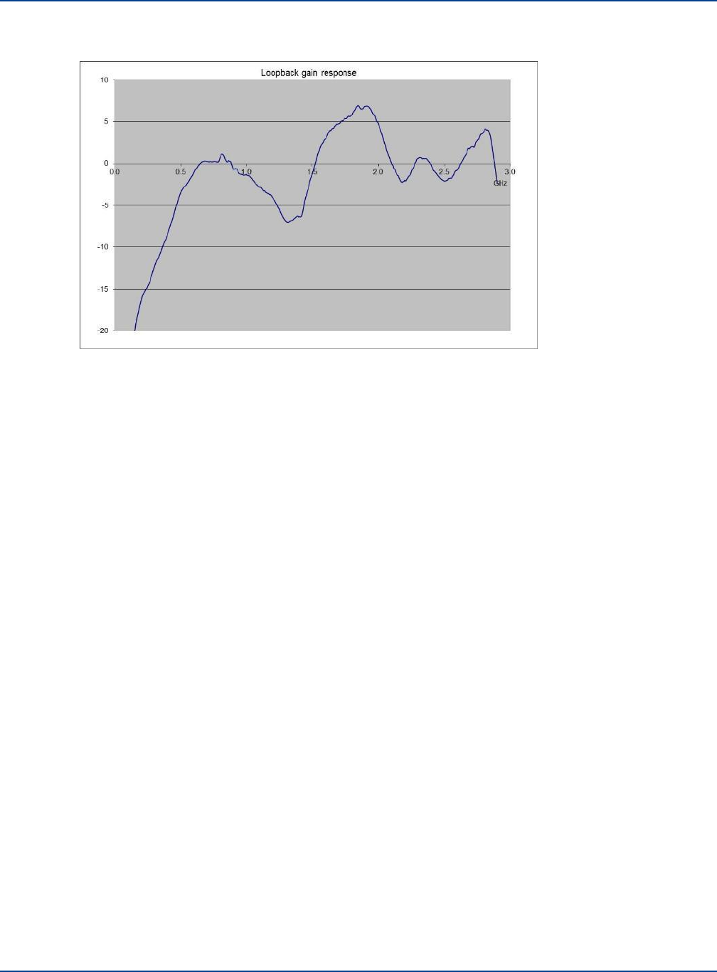
Antenna Requirements
Understanding Antennas
An example loopback (downlink+uplink) gain profile is shown in the graph below:
This graph was obtained by injecting a signal into a double-star system with 1 Remote Unit. The
Remote Unit had a 50dB attenuator connected between Tx antenna output and Rx antenna input. The
test signal was injected into the Service Module input and the resulting signal was measured at the
Service Module output. The system settings were set such that the downlink gain was 25dB (nominal)
and the uplink gain was also 25dB (nominal). Therefore the nominal loop gain was +25+25-50 = 0dB.
The differences from this nominal 0dB that are due to the system gain variation would then have to be
subtracted from the gain variations that would be measured if the 50dB attenuator was replaced with
an antenna.
It is also possible to measure multiple antennas simultaneously as long as the “combining gain” of
multiple antennas is taken into account (approximately 5dB for 8x Remote Unit and 10dB for 64
Remote Unit or more generally 2.4*ln(N) for N* Remote Unit). This method produces a much less
accurate result but is a quicker way of verifying a larger number of antennas simultaneously.
Installation and Configuration 7-3

Connecting Antenna to Remote Units
Understanding Antennas
7.1.3. Uplink/Downlink Balance
Care should be taken not to separate the two antennas by so much distance that the path difference
between Tx and Rx to the mobile affects system performance. Some services are more affected by
uplink/downlink path difference than others, especially those using high dynamic range mobile power-
control such as WCDMA.
There are two WCDMA system effects to be aware of when testing a separated antenna coverage
area:
•
When the mobile is close to the Tx antenna but some distance from the Rx antenna, the initial
call-setup power that the mobile transmits will be lower than expected by the BTS. It is likely
that the BTS will fail to receive the initial call-setup attempt so the mobile will transmit again at
a higher power level. The mobile will continue to ramp up its power level until the BTS receives
and acknowledges the message. This effect can cause longer initial setup times close to the
Tx antenna and in extreme cases may cause the mobile to timeout during call setup. In order
to compensate for this effect the balance of gain between uplink and downlink can be adjusted
to increase the uplink gain. This is usually done in the head-end by moving attenuation from
the uplink to downlink paths. However, in some case the UL/DL balance setting can also be
used within the UNItivity 5000 platform if the uplink gain is not already at maximum.
•
When the mobile is close to the Rx antenna but some distance from the Tx antenna, the initial
call-setup power that the mobile transmits will be higher than expected by the BTS. As long as
the mobile power does not overload either the Remote Unit or the BTS input then this should
not cause a call setup failure.
Note that the path difference between Tx and Rx at the edge-of-cell is likely to be much smaller than
near the antennas due to the effect of the indoor propagation conditions. Where there are no line-of-
sight differences between Tx and Rx the edge-of-cell path difference will be less than 3dB for most
services.
7.2
Connecting Antenna to Remote Units
The Remote Unit has separate connectors for transmit and receive antennas. The choice of antenna
depends on the RF coverage and planned designs for a building, You may need extension cables
depending in where the antennas are placed relative the Remote Unit.
To connect antennas to Remote Units:
1.
Connect the N-type or Mini-DIN male connections into N-type or Mini-DIN female connectors on
the top of Remote Unit Note the markings on the unit for Rx and Tx.
2.
If you haven’t already done so, feed the RF extension cables through from the Remote Unit to the
Antenna.
3.
Connect the N-type or Mini-DIN female connections into N-type or Mini-DIN male connectors to
the RF tails.
4.
Pay attention to the mechanical stress placed on the connector if using large inflexible cable. Use
short flexible jumpers where appropriate.
7-4 Installation and Configuration
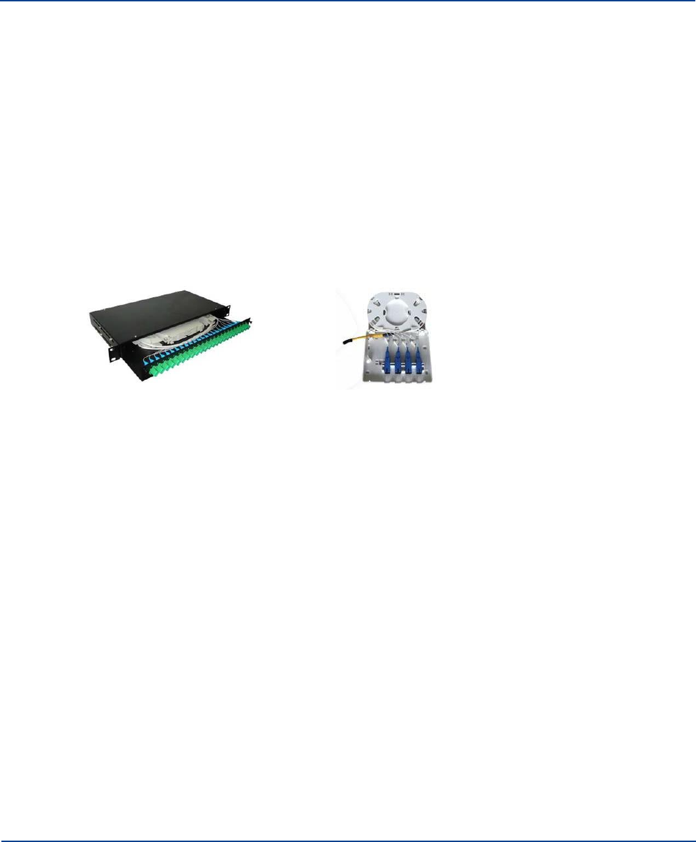
Chapter 8: Infrastructure and Cabling
This chapter provides a general understanding of how the Zinwave equipment fits into your existing or
potential infrastructure.
8.1
Understanding Fiber Infrastructure Cabling
Hubs and Remote Units may be separated by a considerable distance. Primary Hubs and Secondary
Hubs may also be located far from each other. Fiber cabling is used to connect these components. This
connection is referred to as infrastructure cabling. It may form part of the existing structured cabling or
could be installed specifically for UNItivity 5000 or be a combination of both. For example, the existing
cabling may be used to connect Primary and Secondary Hubs as part of a building backbone while new
cabling is run to Remote Unit locations.
Infrastructure cabling is typically terminated on patch panels or small “splice boxes” in the case of
Remote Units.
Patch Panel Termination Splice Box
The infrastructure cable is spliced onto pigtails contained in each termination box to provide a connector
interface into which the Zinwave patch cords are plugged. Regardless of the type of patching, the
concept is the same. Zinwave patch cords are used to connect to all Zinwave components on one end
8-1
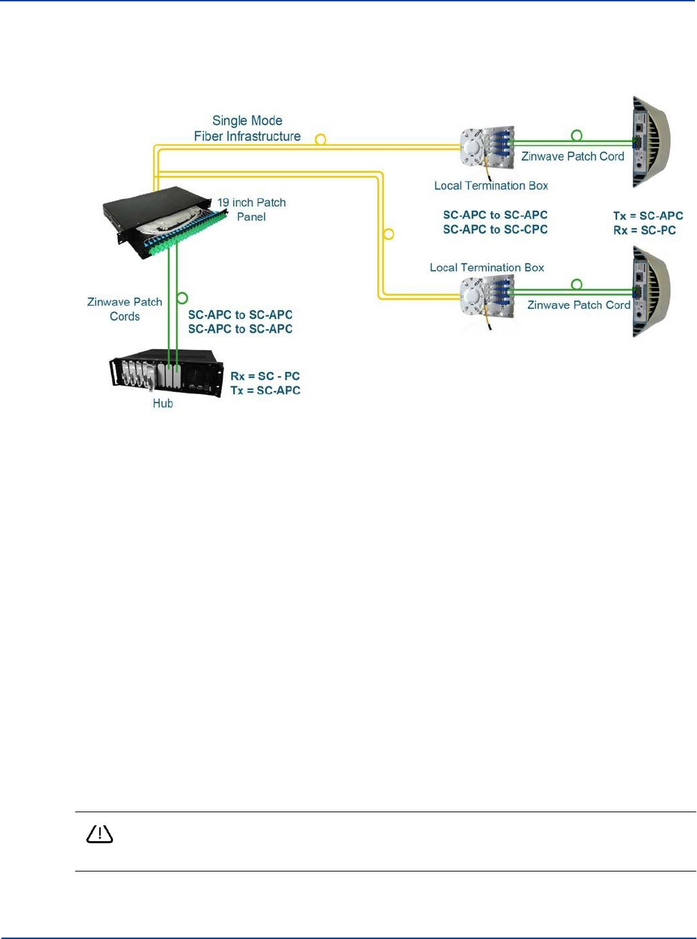
Understanding Fiber Infrastructure Cabling
Infrastructure and Cabling
and a patch type device on the other. Cabling on the other end of the of the patch device must meet
Zinwave specifications. The diagram below shows a conceptual fiber Infrastructure. Note that all
connections to Zinwave equipment are now SC/APC.
The nature of the infrastructure will depend upon the building type and, if applicable, installed cable.
8.1.1. Selecting an Infrastructure Mode
The UNItivity 5000 system uses a laser in the transmit direction and photodiode in the receive
direction, with SC/APC connectors in both directions. The system should be deployed using
Singlemode fibre infrastructure.
The interface to infrastructure equipment is typically achieved using Zinwave supplied patch cords. All
Zinwave supplied patch cords are provided with the correct duplex SC/APC connectors for the Zinwave
equipment, and other optical connectors as specified to match the installed infrastructure.
Any Infrastructure installed between Primary and Secondary and between Secondary and Remote
Units must meet the following criteria
•
Optical Loss:Less than 5dBo
•
Return loss for ALL connections: better than 30dB
Zinwave recommends:
•
Singlemode
•
APC Connector Type:
Caution: Connector types must match (i.e. SC/APC to SC/APC).
Otherwise, there will be an air gap between the connector faces that will create high back
reflection and high optical loss.
8-2 Installation and Configuration
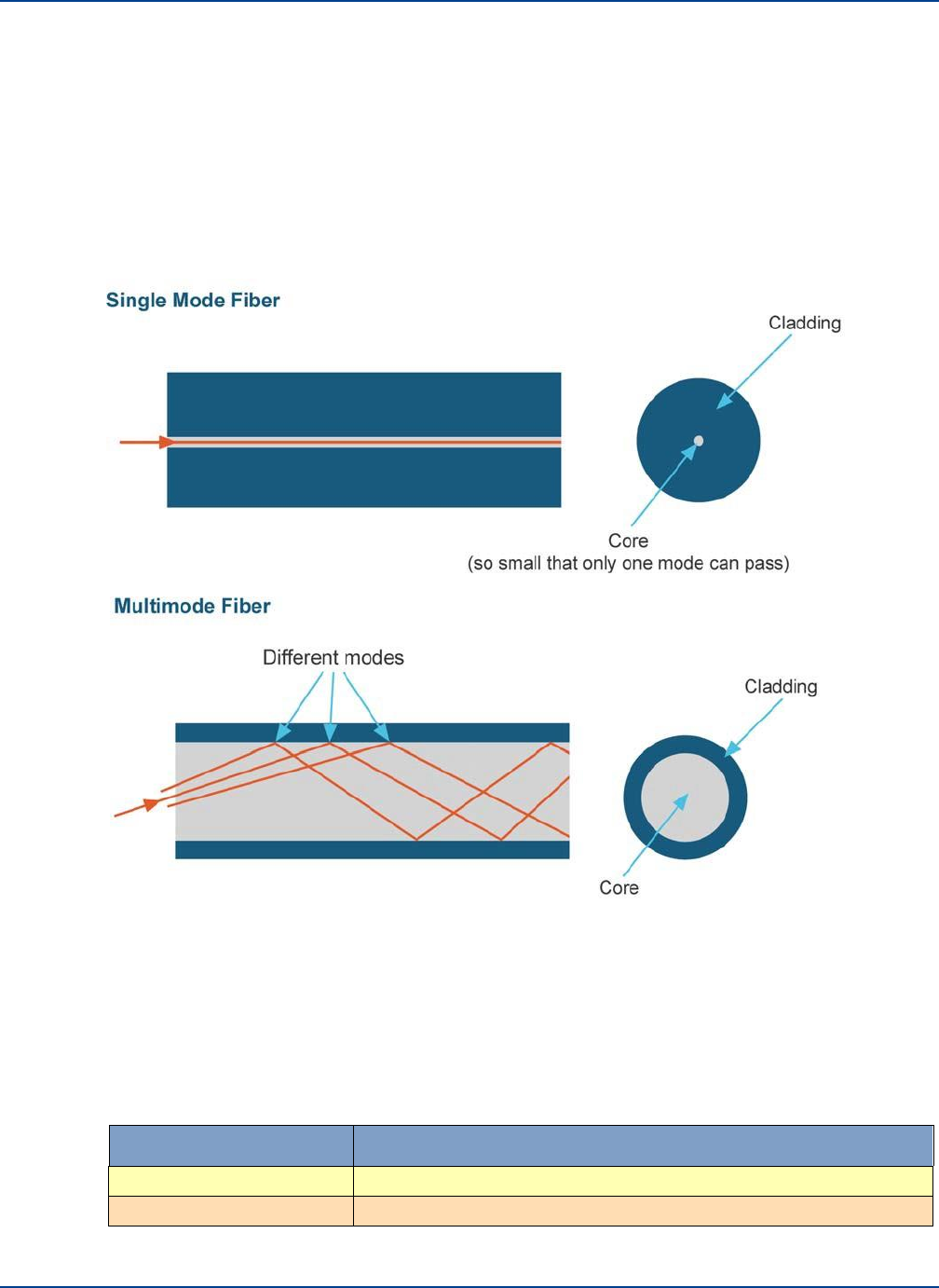
Understanding Fiber Infrastructure Cabling
Infrastructure and Cabling
8.1.2. Types of Optical Fiber cable
Optical fiber cable is generally available in two types: Singlemode and Multimode.
A UNItivity 5000 system is designed for use with Singlemode fiber and APC connectors. Singlemode
optical fiber cables, due to the very small core size (9 µm) transmit a single ray of light while
Multimode optical fiber cable, with a larger core size (62.5 µm or 50 µm), carries multiple light rays with
different reflection angles within the fiber core. Multimode fibers should not be used with the UNItivity
5000 system.
Keeping optical reflections to a minimum is important to achieve good RF performance an RF over
fiber DAS system. Single mode fiber is less prone to reflections than multimode fiber. The majority of
reflections occur at points of fiber connection within the whole system. This includes Optical Module,
Secondary Hub and Remote Unit but more importantly at intermediate connections such as patch
panels and fiber splices. Angle polished (APC) connectors should be used throughout to minimize
reflections.
Guide to Fiber Colors
Buffer/Jacket Color
Meaning
Yellow
single-mode optical fiber
Orange
62.5 µm multi-mode optical fiber
Installation and Configuration 8-3

Understanding Fiber Infrastructure Cabling
Infrastructure and Cabling
8.1.3. Infrastructure Interface
The interface used to connect to the Infrastructure will depend upon the connector type preferred or
utilized in specific installation scenario.
APC connectors are strongly recommended. Connector types must match (APC to APC and PC to
PC) otherwise, there will be an air gap between the connector faces that will create high back
reflection and high optical loss. See “Ferrule Types” on page 8-6 for more information on connector
types.
8-4 Installation and Configuration
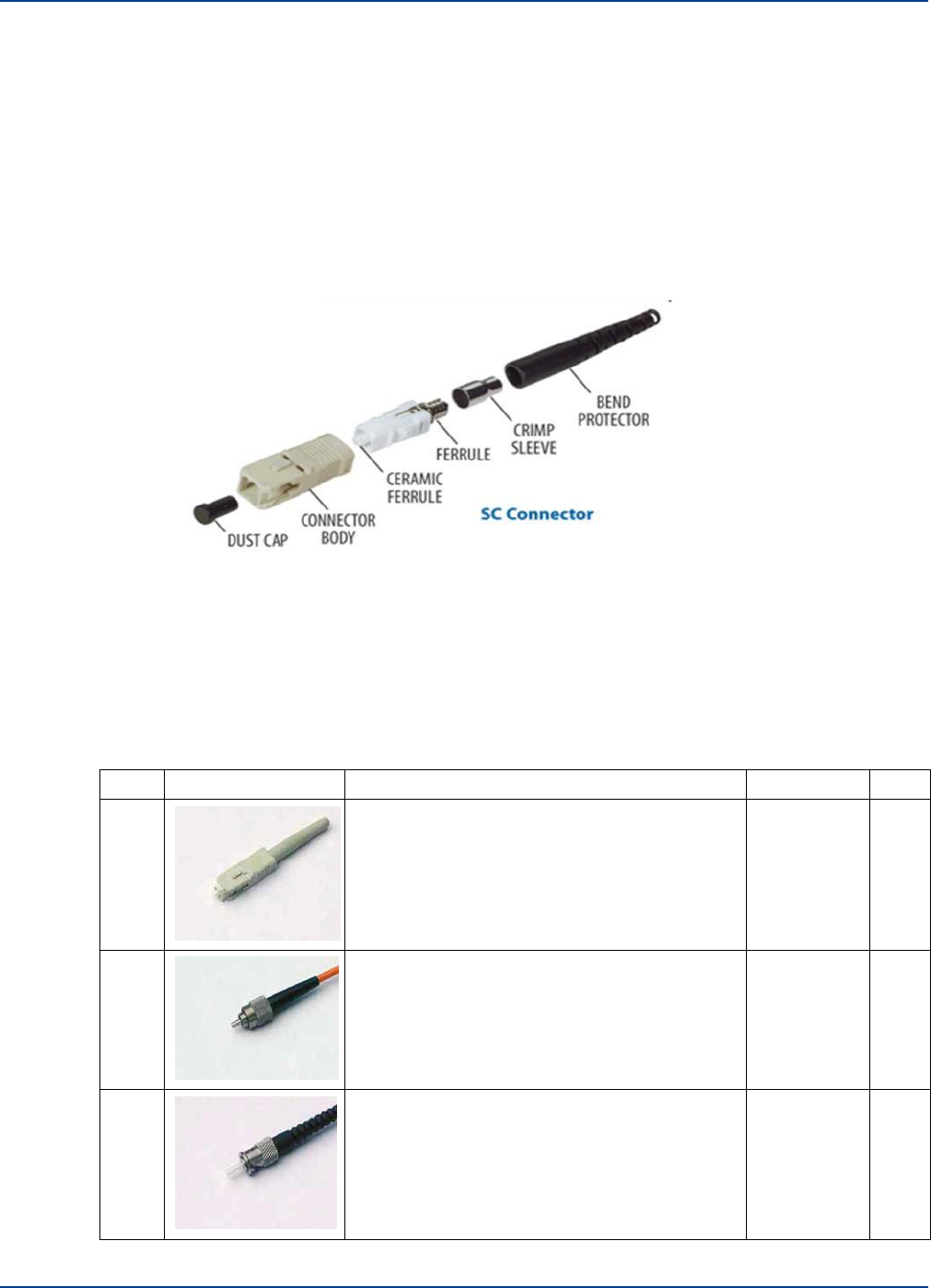
8.2
Fiber Optic Connectors
Fiber Optic Connectors
Infrastructure and Cabling
When connecting to Zinwave Patch Cords care must be taken to ensure that the correct connector and
fiber type is provided.
A fiber optic connector consists of two key elements.
•
Connector Body Type
•
Ferrule Type
There are a wide variety of connector body types used in infrastructure cabling some of the most
common types are shown below.
There are two main groupings standard and Small Form factor. The small form factor connectors have
a 1.25mm (0.05 in) ferule compared to the ferule size in “standard connectors of 2.5mm (0.1 in).
Zinwave recommends the use of APC connector type.
Type
Description
Cable Type
APC
SC
SC is a snap-in connector that is widely used
in Singlemode systems for its excellent
performance. It's a snap-in connector that
latches with a simple push-pull motion. It is
available in both PC, UPC, and APC.
Singlemode
and
Multimode
Yes
FC
Commonly used in Singlemode networks and
is available in PC, UPC and APC variants. It
has an outer body that screws in to hold the
ferule firmly in place. It has a key ensuring that
the fiber is correctly aligned.
Singlemode
and
Multimode
Yes
ST
Popular connector for Multimode networks. It
has a bayonet mount and a long cylindrical
ferrule to hold the fiber. The main body is
spring loaded and can cause problems (high
loss) if not seated properly.
Singlemode
and
Multimode
No
Installation and Configuration 8-5
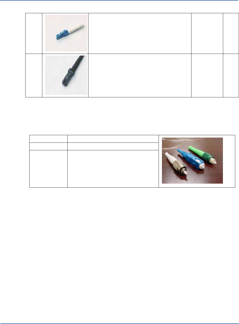
Fiber Optic Connectors
Infrastructure and Cabling
LC
LC is a newer connector that uses a 1.25
mm ferrule, half the size of the ST.
Singlemode
and
Multimode
Yes
MTR
J
MT-RJ is a duplex connector with both fibers in
a single polymer ferrule. It uses pins for
alignment and has male and female versions.
Multimode only.
Multimode
only
No
8.2.1. Ferrule Types
As shown above some of these connectors can be designated either APC or PC, this refers to the
Ferrule within the connector body. The TIA 568 color code for connector bodies and/or boots is:
Green
Singlemode APC (angled) connectors
Blue
Singlemode (UPC)
Beige
Multimode
Attaching a connector to an optical fiber cable will cause some of the light traversing that optical fiber
to be lost. Regardless of whether the connector was installed in the factory or the field, its presence will
be responsible for some light being reflected back towards its source, the laser. This is known as
return loss (RL) and high levels of unwanted reflections can degrade the signal’s performance.
The amount of optical return loss generated is related to the type of polish that is used on the
connector. There are three basic types of polish:
•
APC
•
UPC
•
PC
8-6
Installation and Configuration
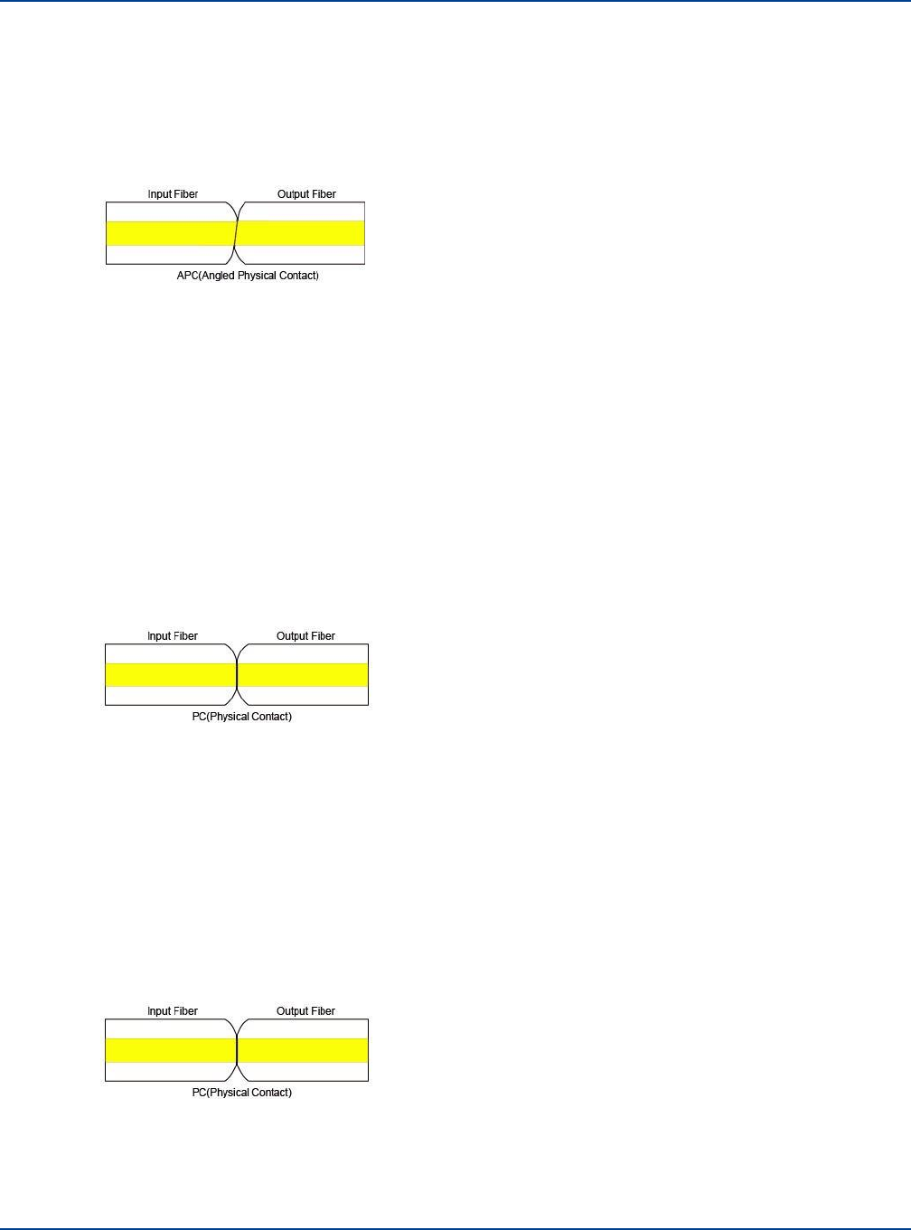
Fiber Optic Connectors
Infrastructure and Cabling
8.2.1.1.
APC (Angled Physical Contact)
The “angled physical contact” (APC) connector is best as it offers the lowest return loss characteristics
of connectors currently available. In an APC connector, the end face of a termination is polished
precisely at an 8-degree angle to the fiber cladding so that most RL is reflected into the cladding where
it cannot interfere with the laser source.
As a result, APC connectors offer a superior RL performance with atypical back reflection of better
than 60dB.
8.2.1.2.
UPC (Ultra-polished Physical Contact)
Typical Back Reflection: <-35dB for Singlemode fiber
UPC connectors are very similar to PC connectors in that the ferrules faces are flats but have a much
better return loss, which can be better than 50 dB. This performance is due to an improved polishing
technique applied to the face and to the curvature at the ferrule end. The rounded finish created during
the polishing process allows fibers to touch on a highpoint near the fiber core where light travels UPC
polish is available for almost all Singlemode connectors--namely FC, SC, ST, but, unlike PC
connectors, is not available for Multimode fibers.
When using UPC connectors it is essential to confirm optical back-reflection levels using an OTDR as
described in the sections below.
8.2.1.3.
PC (Physical Contact)
Typical Back Reflection: <-35dB for Singlemode fiber
The “physical contact” (PC) connector is probably the most common type of ferrule face. It is available
on both Singlemode and Multimode fibers but due to the flat face has reduced return loss and is more
prone to dirt and poor connections.
When using PC connectors it is essential to confirm optical back-reflection levels using an OTDR as
described in the sections below.
Installation and Configuration 8-7

Handling Optical Fiber
Infrastructure and Cabling
Note: UPC can be mated to PC connectors as both have flat faces but APC connectors can only be
connected to APC connectors due to the face angle.
8.3 Handling Optical Fiber
Follow the recommendations listed in this section when handling Optical Fiber.
Observe minimum bend radius (typical 30mm):
•
Alters guiding properties of fiber introduces loss
•
Often reversible, but non-reversible defects hard to detect
Ensure good connections:
•
Especially with pluggable connectors (SC, LC)
•
Risk of latching only one of the connectors in duplex configuration
Keep connectors clean:
•
Always use the provided dust caps until connection is made
•
Dirty connectors introduce loss and reflections
•
Dirt can also cause defect on connector facet
•
Clean connectors with alcohol-saturated wipes and lint-free tissues
Don’t mix different fiber types
•
Insertion loss from MMF SMF is >20dB
8.4 Diagnosing Fiber connections
To diagnose fiber connections see “Performing Diagnostics and Testing” on page 17-1.
8.5 Link Calibration
The system performs gain self-calibration when a link is established using internally generated signals
and measurement circuits. The self-calibration is designed to optimize the system gain settings for the
required downlink output power and to minimize uplink noise figure for the required maximum input
signal.
Part of the self-calibration includes compensation for installed cable and connection losses.
Measurements are made in both the optical and RF domains.
8-8 Installation and Configuration

Link Calibration
Infrastructure and Cabling
Installation and Configuration 8-9

Link Calibration
Infrastructure and Cabling
8-10 Installation and Configuration
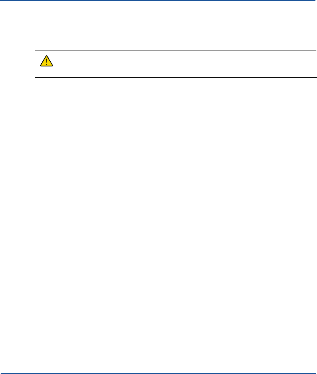
Chapter 9: Making Connections
This chapter provides a general understanding of how to connect equipment within the system.
9.1
Connecting Service Modules to RF inputs or POI
Warning: If the service module is connected directly to the output of a BTS or any RF input
source, maximum power delivered to a service module must not exceed 15dBm. Use
additional equipment to attenuate the power.
You can connect Service Module inputs (e.g. BTS, via a POI) only to the Primary Hub.
To connect into the Service Module:
1.
Connect the N-type male connections into N-type female connectors on the Service modules
inserted in the rear of the Primary Hub.
2.
Pay attention to the mechanical stress placed on the connector if using large inflexible cable. Use
short flexible jumpers where appropriate.
9.2
Optical Connections
Whether connecting an Optical Module to the fiber infrastructure, a Secondary Hub or a Remote Unit,
you will typically terminate the connection to the Zinwave hardware using a Zinwave optical patch cord..
When installing any fiber, pay careful attention to cleanliness and good installation practice.
The following instructions describe how to connect to Zinwave optical interfaces.
9.2.1. Connecting Optical Modules to Infrastructure or Secondary Hubs
To connect Optical Modules (installed in a Primary Hub) to infrastructure or Secondary Hubs:
1.
Remove the protectors from the SC/APC connectors on the Optical Module and the patch cord.
2.
Plug the duplex SC/APC Green connector into an Optical Module (note: on Optical Module or
Secondary Hub, the INput port is at the top, and the OUTput port is at bottom).
3.
Repeat the above steps for the other end of the optical patch cord. Whether it is connected to an
optical patch panel or a Secondary Hub, make sure to abide by the recommendations in
“Understanding Fiber Infrastructure Cabling” in section 8-1.
Important: It is very important that only Green duplex SC/APC connectors are inserted into the
SC/APC connectors on the Zinwave UNItivity 5000 hardware. The installer needs to ensure
that the OUT port from the Optical Module or Secondary Hub is connected to the IN port on
the Remote Unit, and vice-versa. If Zinwave hardware is connected directly using Zinwave
optical patch cords, the keying of the duplex SC/APC connectors on each end will ensure that
these connections are correct.
9-1

Connecting the PSU to Remote Units
Making Connections
9.2.2. Connecting Optical Modules or Secondary Hubs to Remote Units
To connect Optical modules or Secondary Hubs to Remote Units:
1.
For Remote Units, install fiber optic cable of sufficient length to reach the Remote Unit, noting the
need for the Zinwave patch at the each end.
2.
Remove the protectors from the SC/APC connectors on the Optical Module and the patch cord.
3.
Plug the duplex SC/APC Green connector into an Optical Module (note: on Optical Module or
Secondary Hub, the INput port is at the top, and the OUTput port is at bottom).
4.
Remove the protectors from the SC/APC connectors on the Remote Unit and the patch cord.
5.
Insert the duplex SC/APC Green connector into the Remote Unit (note: on Remote Unit, the
INput port is at the right, and the OUTput port is at the left.
Important: It is very important that only Green duplex SC/APC connectors are inserted into the SC/APC
connectors on the Zinwave UNItivity 5000 hardware. The installer needs to ensure that the OUT port from
the Optical Module or Secondary Hub is connected to the IN port on the Remote Unit, and vice-versa. If
Zinwave hardware is connected directly using Zinwave optical patch cords, the keying of the duplex
SC/APC connectors on each end will ensure that these connections are correct.
9.3 Connecting the PSU or Secondary Hub to Remote Units
9.3.1. Power Distribution Requirements
Power for Remote Units is generally supplied from a centrally located source – either a dedicated
PSU or a Secondary Hub - that drives multiple Remote Units. The distance of the Remote from the
centralized location depends upon the cable type used. Regardless of the cable used, the maximum
loop resistance should generally be kept below 8 ohms to ensure the minimum input voltage
requirement of the Remote Unit is not violated.
Copper wire containing 2 cores is typically used to carry 48V power to Remote Units. This can either
be run in parallel with fiber infrastructure, or as part of a composite cable.
With AWG 22, the maximum distance that can be achieved is approximately 300 m (~1000 ft). If
greater distances are required, larger gauge cable may be used. The Phoenix Contact connectors
used on the Zinwave equipment support wire thickness up to AWG 12. The table below provides
typical cables distances against AWG.
Cable Type
AWG
Conductor
Diameter
(in)
Conductor
Diameter
(mm)
Individual
Conductor
Area
(mm2)
Total
Conductor
(mm2)
Nominal
Loop
Resistance
Ω
Remote
Unit
Distance
(m)
Remote
Unit
Distance
(ft)
Single Pair of
Conductors
12
0.0808
2.05
3.31
3.31
8
789
2589
Single Pair of
Conductors
13
0.072
1.83
2.63
2.63
8
627
2058
Single Pair of
Conductors
14
0.0641
1.63
2.08
2.08
8
496
1628
9-2 Installation and Configuration
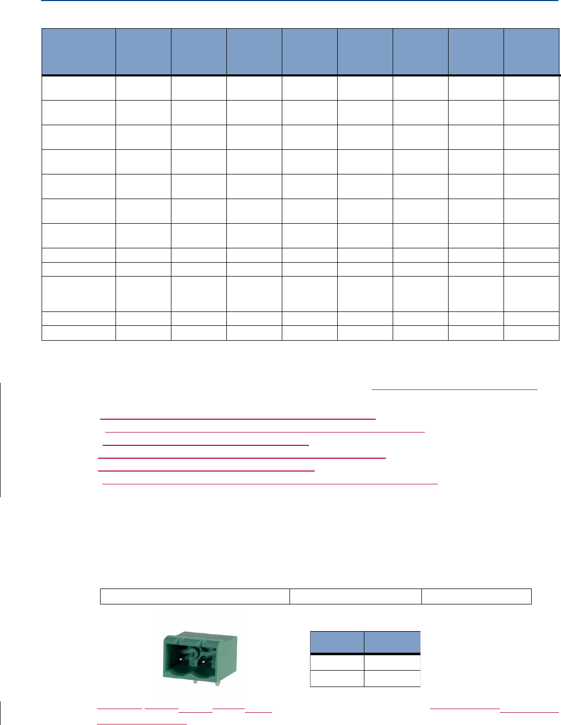
Connecting the PSU to Remote Units
Making Connections
Cable Type
AWG
Conductor
Diameter
(in)
Conductor
Diameter
(mm)
Individual
Conductor
Area
(mm2)
Total
Conductor
(mm2)
Nominal
Loop
Resistance
Ω
Remote
Unit
Distance
(m)
Remote
Unit
Distance
(ft)
Single Pair of
Conductors
15
0.0571
1.45
1.65
1.65
8
393
1290
Single Pair of
Conductors
16
0.0508
1.29
1.31
1.31
8
312
1024
Single Pair of
Conductors
17
0.0453
1.15
1.04
1.04
8
248
814
Single Pair of
Conductors
18
0.0403
1.02
0.82
0.82
8
196
644
Single Pair of
Conductors
19
0.0359
0.91
0.65
0.65
8
155
509
Single Pair of
Conductors
20
0.032
0.812
0.518
0.518
8
124
407
Single Pair of
Conductors
21
0.0285
0.723
0.41
0.41
8
98
322
CAT 6 (4 pairs)
22
0.0253
0.644
0.326
1.304
8
311
1021
CAT 6 (4 pairs)
23
0.0226
0.573
0.258
1.032
8
246
808
CAT5
(4pairs)|CAT 6
(4 pairs)
24
0.0201
0.511
0.205
0.82
8
196
644
CAT 5 (4 pairs)
25
0.0179
0.455
0.162
0.648
8
155
509
CAT 5 (4 pairs)
26
0.0159
0.405
0.129
0.516
8
123
404
9.3.2. Understanding the Connectors & Cabling
Cabling between the PSU or Secondary Hub is not supplied. You will typically use a 2 core cable.
Ensure that the 48 V cable used is one of the following:
i. 2-core power cable listed in accordance with NEC 645.5(B)
ii. Or Installed in an enclosed raceway
iii. Or be installed in accordance with NEC 721.135(C)
iv. Or be type CMP< CMR, CN or CMG
v. Or be listed type DP cable suitable for use under raised floors
Termination of each cable type will depend on the PSU version used, and you may need to utilize an
adapter to make the final connection. Ensure the 48V connection is made with correct polarity.
Note: If you use your own 48V power supply, rather than the Zinwave Remote PSU or Secondary
Hub, the cable instructions are the same as for the Zinwave equipment
The 48V power connector used on the Zinwave Secondary Hub and Remote Unit is:
TERMINAL BLOCK HDR 2POS 5.08MM
PHOENIX CONTACT
P/N: 1757242
A suitable mating Mating socket plugs from the same series of connector should be usedare provided
and should be used to terminate the 2-core cable.
The 1U Rack-mount PSU uses screw terminals, so the wire pair may be connected directly in that
case.
Pin
Detail
Left
48V (+)
Right
0V (-)

Installation and Configuration 9-3
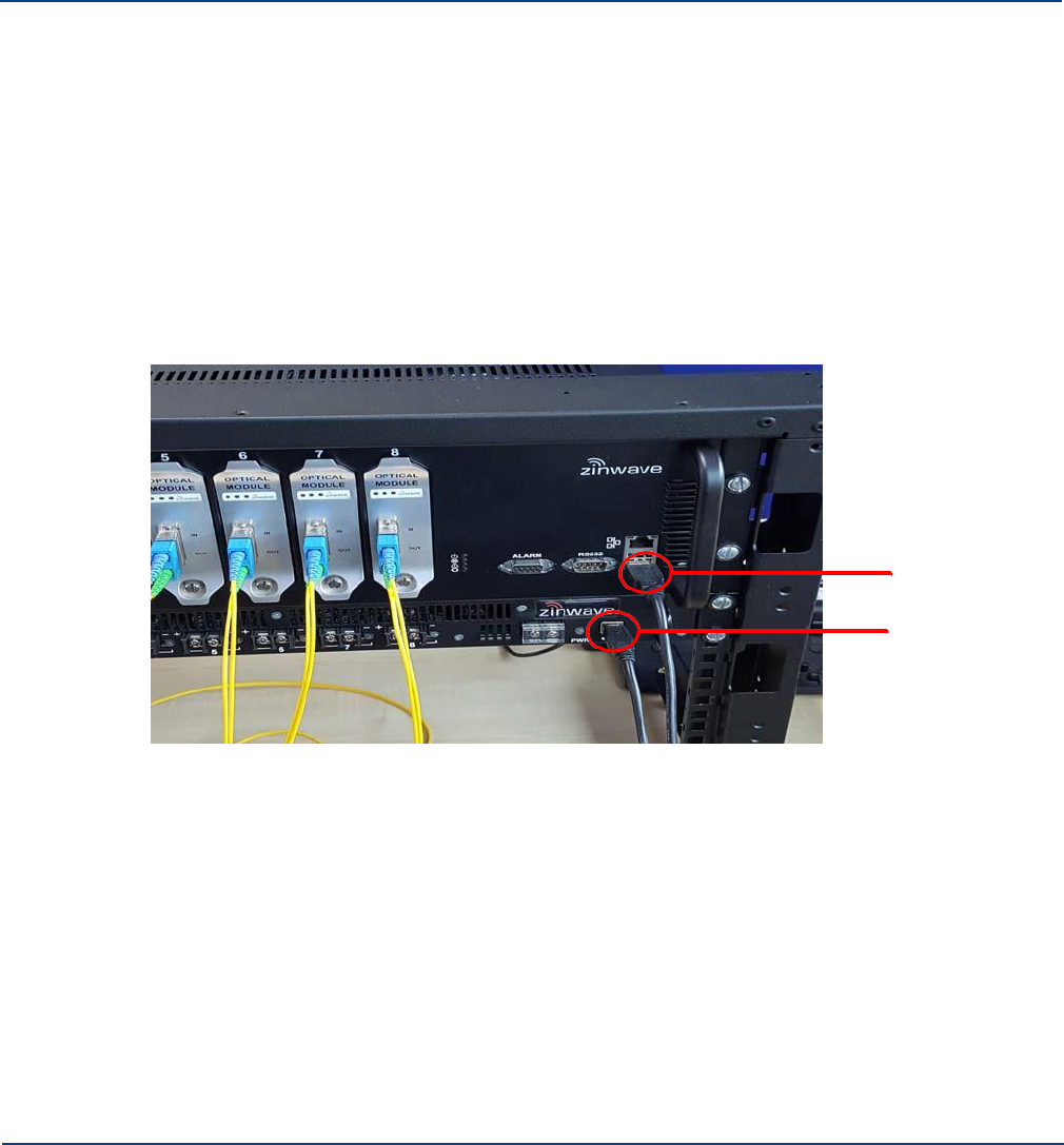
Connecting the PSU to a Hub
Making Connections
9.4 Connecting the PSU to a Primary Hub
You can control and monitor the Rack-Mount PSU using the Primary Hub GUI. For this operation, a
physical connection must be made between the PSU and the Primary Hub.
To physically connect a PSU to a Primary Hub:
1.
Using a USB (Type A) to USB (Type B) connector, insert the Type B end into the PSU connector
slot on the PSU.
2.
Insert the Type A end into the USB connector slot on the Primary Hub.
USB Type A
USB Type B
3.
The PSU will be detected and can be monitored via the Configuration GUI. See “PSU Setup” on
page 12-10 for details.
9-4 Installation and Configuration
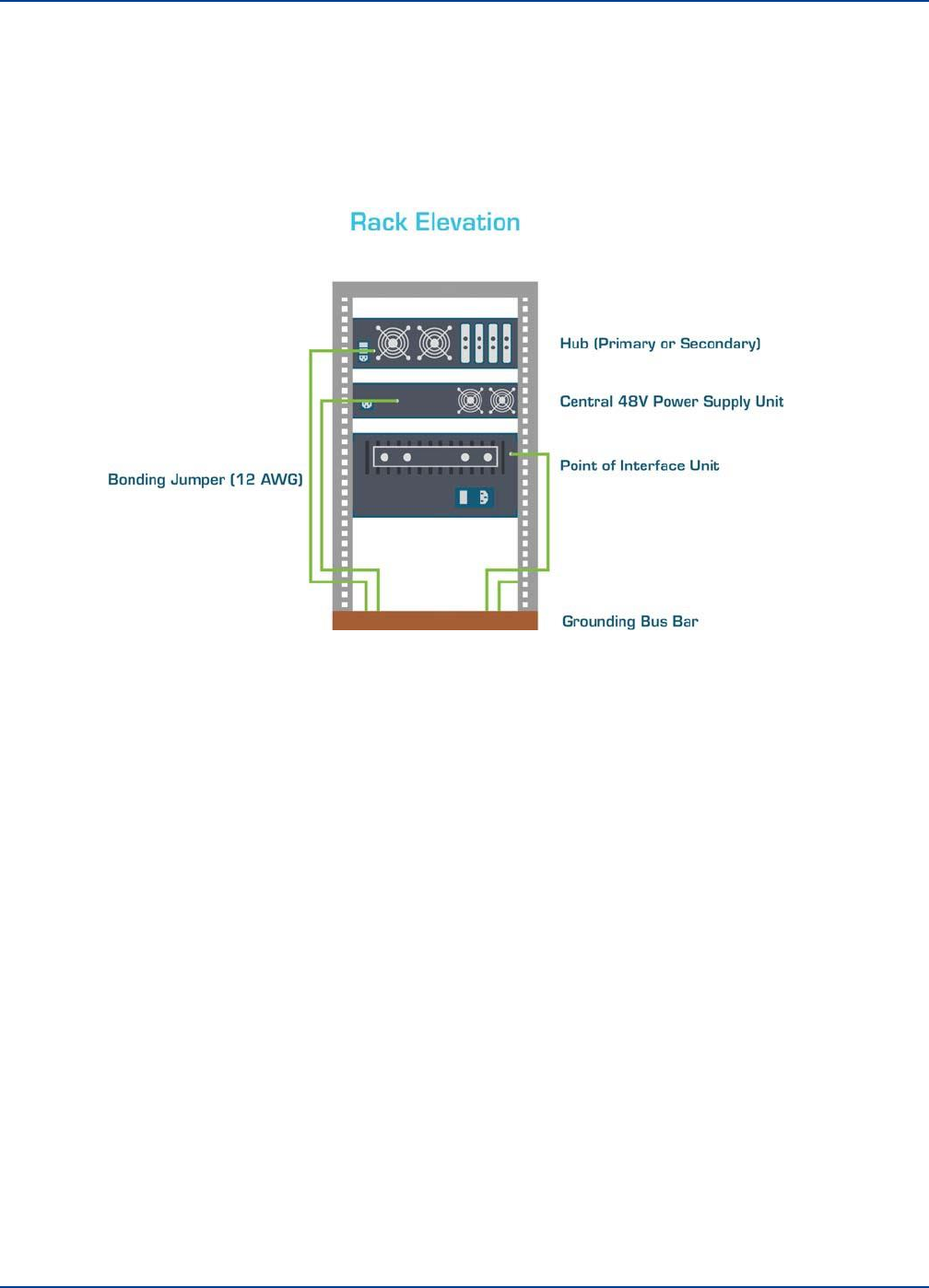
9.5 Grounding Rack Mounted Equipment
Grounding Rack Mounted Equipment
Making Connections
The Hubs, PSU, and POI are rack mounted. Each has an M3 threaded Grounding Post that should
be connected via Bonding Cable (12 AWG) to the Grounding Bus Bar in the rack. the Rack itself is
also grounded via an M5 post.
To ground the equipment:
1.
Using bonding cable with solid green outer sheath, connect the grounding post of each unit to the
rack grounding bus bar.
2.
Attach the bonding cable using a retaining washer and ring terminal to each grounding post.
Note: Bonding cable should be 18 AWG minimum with 12 AWG recommended.
Installation and Configuration 9-5

Grounding Rack Mounted Equipment
Making Connections
9-6
Installation and Configuration

Chapter 10: Performing Basic Configuration
The following procedures are intended to be executed after the hardware installation is complete. All
hardware has been installed and configured with at least an IP address. All equipment is connected and
the system is ready to be configured. See “Performing a Basic Installation” on page 4-1 for a guide to
basic installation.
To Configure UNItivity 5000 after basic installation:
1.
Gather all needed input information such as measured signal input powers including any allowance
for pilot back off and relative power levels generated by the coverage tool.
This will provide you the following information:
•
Input power from each Service
•
Service mix and allocation to Remote Units
•
Composite power settings
•
Results of any coverage calculations for each Remote Unit
2.
Access the GUI and configure the Hub type for each Hub. See “Accessing the GUI” on page 11-1
and “Setting the Hub Type” on page 12-1.
3.
Make sure power is on for every unit. See “Powering the Hub” on page 5-5 and “Powering Remote
Unit” on page 6-3.
4.
Make sure all modules have been inserted. See “Installing and Populating Hubs” on page 5-1.
5.
Make sure all connections have been made. Power and data and all units are on. Self discovery
happens and LEDs are green. See “Start-up Sequence” on page 3-4.
Note: Indicator lights will adjusts as system setup configuration is corrected.
6.
Login to the Primary Hub. See “Accessing the GUI” on page 11-1.
7.
Set date and time on Primary Hub in Hub setup. See “Setting Hub Date and Time” on page 12-7.
This will propagate to all other Hubs.
8.
On the Primary Hub check and, if necessary, upgrade to the latest software version. See “Update
Firmware” on page 12-1.
9.
Enter the System Setup information supplied to you for all Hubs and Remotes. See “Understanding
System Setup” on page 14-1.
10.
Review system status and RU calculations. See “Understanding System Status” on page 13-1.
11.
Enter sensitivity and alarms. See “Service Module Downlink Sensitivity” on page 15-8, “RU Uplink
Sensitivity” on page 15-5, and “Understanding Alarms and Reporting” on page 16-1.
12.
Enter LAN setup, if desired. See “LAN Settings for Hubs” on page 12-8.
13.
Save config file and save system layout. See “View System Layout” on page 13-8 and “Configuration
Files” on page 15-1.
10-1

Performing Basic Configuration
10-2 Installation and Configuration

Chapter 11: Understanding the Configuration
GUI
A Configuration Graphical User Interface (GUI) is available to configure your equipment locally or
remotely via ethernet. The GUI is hosted on the Primary Hub, and is used to configure and monitor the
Primary Hub and all connected Secondary Hubs and Remote Units. This section describes how to
access the GUI and the general features of this interface. Specific configuration items are located in their
respective sections.
Screen captures in this manual are shown using the Chrome browser. Windows may appear slightly
different based on your browser; however, features are the same.
11.1
Supported Browsers
The Configuration GUI is web-based application. It runs on a variety of browsers including: Windows
Explorer, Mozilla Firefox, Google Chrome, and Safari.
11.2
Initial Stand-alone Access
In order to access the GUI from a stand-alone PC via direct ethernet connection, you need to match the
PC’s IP address to the same subnet as the default Primary Hub address.
To change the IP address of the standalone PC:
1.
Set the standalone PC’s IP address to192.168.0.1 (the default Primary Hub IP address is
192.168.0.2)
2.
Make an Ethernet connection from the standalone PC to the Primary Hub (either a crossover or
straight-through Ethernet cable can be used).
3.
Connect one end of the Ethernet cable to the network port on the front of the Primary Hub.
4.
Connect the other end of the Ethernet cable to the standalone PC.
5.
Access the GUI as described in “Accessing the GUI” on page 11-1 and go to the Hub Setup page to
change the IP address. See “LAN Settings for Hubs” on page 12-8.
11.3
Accessing the GUI
The GUI is accessible via Web browser through a secure connection (https). For initial configuration of a
device, you need local access via ethernet to the front of the Primary Hub. After that, you can access
the Hubs and Remote Units remotely on the network you created during the initial setup. Every Primary
Hub is delivered with the same default IP address https://192.168.0.2.
To access the GUI:
1.
Open the desired browser.
2.
In the address line, enter https://ip_address.
where the ip_address is the address of the device you wish to configure. For an initial configuration
the IP address is 192.168.0.2. If you changed it in “LAN Settings for Hubs” on page 12-8, use that
address.
11-1
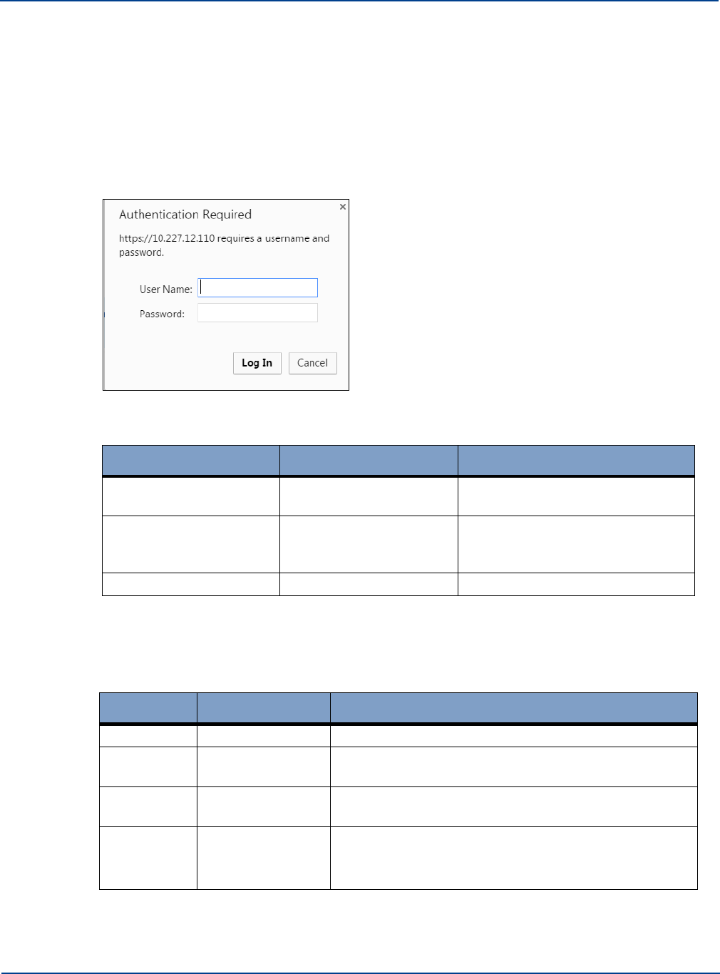
Accessing the GUI
Understanding the Configuration GUI
3.
Press Enter.
A Security Certificate authorization may appear depending on if the PC you are using to access
the device has previously been used. If it appears go to step 5. If not the Login window appears,
go to step 5.
4.
Accept the Security Certificate.
Depending on your browser, a series of acceptances may available to accept the security
certificate. Click through the options to accept the Certificate. You may need to select advanced
options to see all acceptance options.
The Login window appears.
5.
Enter the username and password. There are three privileges levels available.
Username
Default Password
Description
viewer
View system status but cannot
make any changes.
basic
installer
View system status and can make
only a subset of configuration
changes.
advanced
supervisor
View and change all options.
See “Changing User Passwords and Timeouts” on page 11-5 for information on changing
passwords.
The table below iterates specific items available to a Basic user.
Feature
Section
Permission
Event Log
USB Event Log
Start and stop USB Event logging.
Hub Setup
Date and Time
Can change only the current time and date settings in
this section.
Hub Setup
Alarm Handling
Can change only the severity of a warning (Amber or
Green) for Warning LEDs.
Hub Setup
Alarm Handling
Can clear any warning relay or fault relay which has
triggered in the system.
11-2 Installation and Configuration
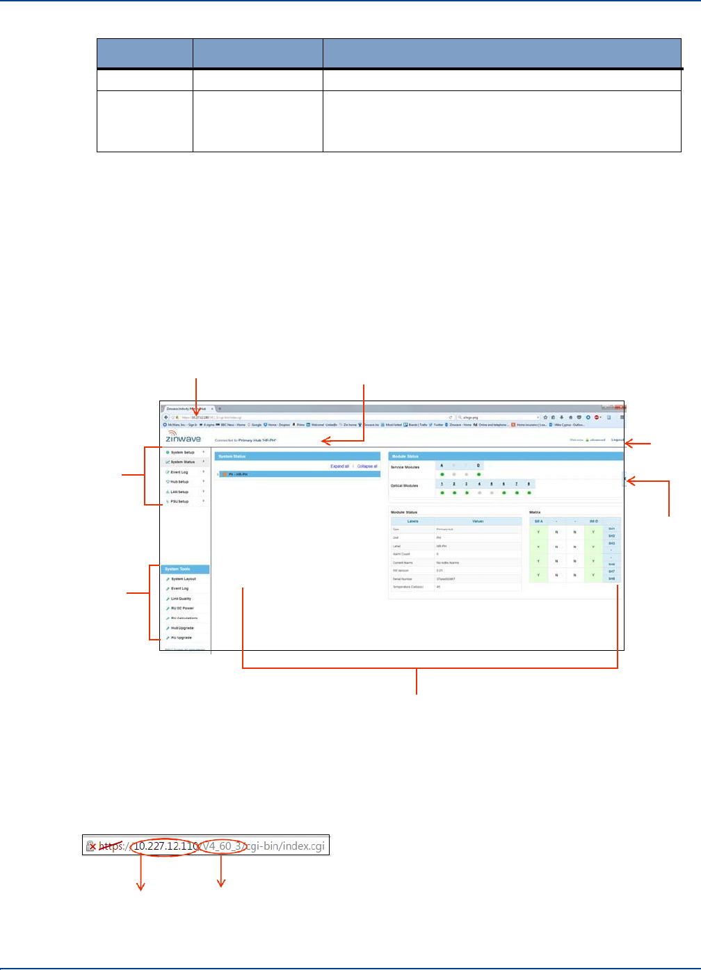
Understanding the Main Window
Understanding the Configuration GUI
Feature
Section
Permission
Hub Setup
Security Settings
Can change only the Basic level of password.
Hub Setup
Security Settings
Can change the inactivity timeout value, but cannot set
to keep logged in.
6.
Click Log In.
On successful login, the System Status window appears. The left navigation menu allows access
to all other screens in the application. See “Left-Navigation Area” on page 11-4.
11.4
Understanding the Main Window
Once logged in, the Main Window is displayed. Depending on the browser used, the look and feel may
differ slightly, but the functionality remains the same. The GUI opens to the System Status page by
default and displays the Hub to which the PC is connected.
Address bar Hub Type
Left-
Navigation
bar
Login bar
Help Button
System
Tools
Display Area
11.4.1. Address Bar
The address bar displays the IP address of the Hub you are currently logged into. It also shows the
version of the software installed on the Hub.
IP Address Current Version
Installation and Configuration 11-3
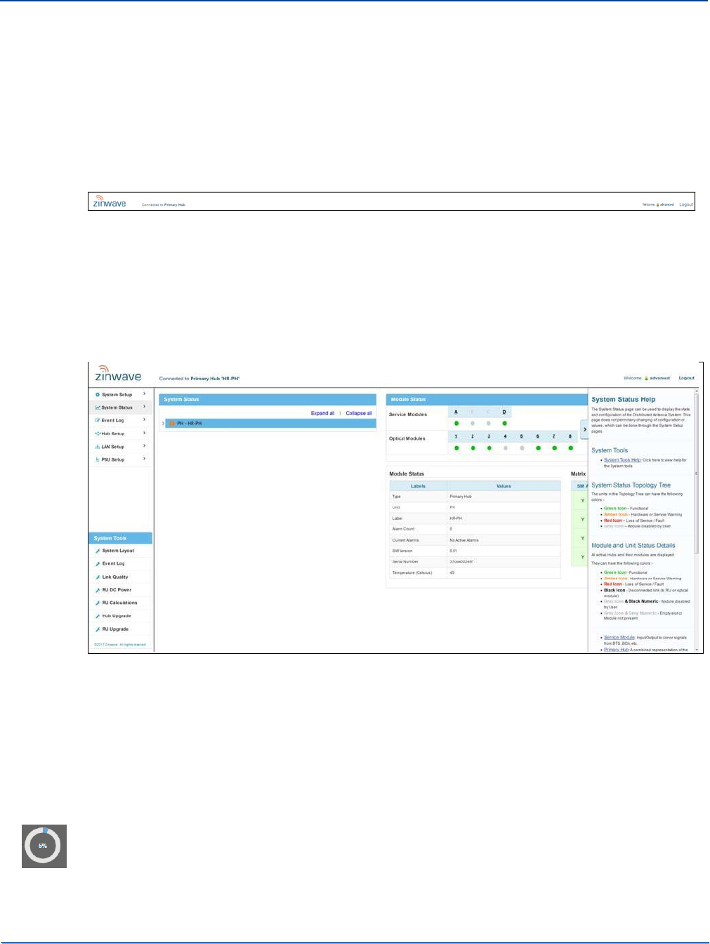
Understanding the Main Window
Understanding the Configuration GUI
11.4.2. Left-Navigation Area
The Left-Navigation area displays the top-level functions for the system.
11.4.3. Login Bar
The login bar shows you who is logged into this application.
11.4.4. Help Button
The Help Button is available on the right-side of the screen.
To access help:
1.
Click the arrow Help button on the right side of the screen.
The help window opens with help specific to your current screen.
2.
View the help and click through to get to additional information, if desired.
11.4.5. Display Area
The Display area shows the items clicked in the left-navigation bar or with the current screen.
11.4.6. Progress Indicator
Throughout the use of the application, the progress indicator is displayed. This indicates that the
system is gathering or calculating information. When the task is complete, the desired information or
page is displayed.
11-4 Installation and Configuration
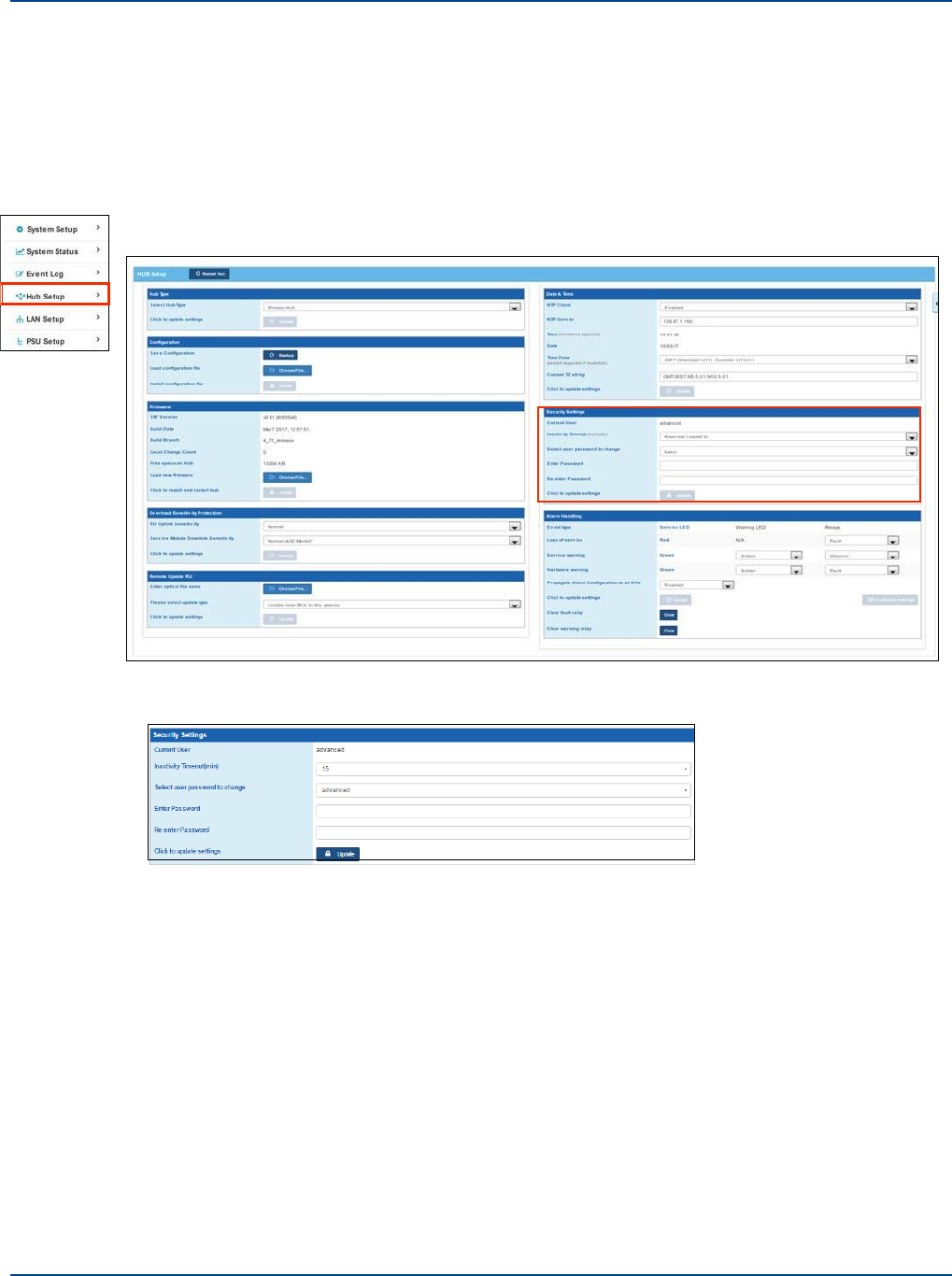
Changing User Passwords and Timeouts
Understanding the Configuration GUI
11.5 Changing User Passwords and Timeouts
As an Advanced user, you can change the password and inactivity logout for users on a particular
Hub.
To change User Security settings for a Hub:
1.
Click Hub Setup in the left navigation bar.
The Current user is shown in the Security Settings pane.
2.
Select the desired amount of minutes from the Inactivity Timeouts pulldown in the Security
Settings pane to allow inactivity in the Configuration GUI before forcing a logout.
Advanced users can also choose to be kept logged in.
3.
Select the user type password to change from the pulldown.
4.
Enter a new password
5.
Re-enter the new password.
6.
Click Update.
Installation and Configuration 11-5

Changing User Passwords and Timeouts
Understanding the Configuration GUI
11-6 Installation and Configuration

Chapter 12: Initial System Setup
This chapter provides the basic configuration setup items to get a system up and running.
Note: If you wish to setup SNMP during the initial setup of the system, see “SNMP” on page 16-10.
12.1
Connection to DAS System
The entire DAS system is setup and configured via the Primary Hub.
Access the GUI on your Primary Hub using a Web Browser, as described in Section 11.
12.2
Update Software
Equipment is shipped with the latest version of software at the time of manufacture; however, updates
may have been made after shipping. The latest version of software is always available via your Zinwave
supplier or from the support area on our website www.zinwave.com (Registration is required). A UNItivity
5000 software update will update the Primary Hub software, as well as firmware on connected Secondary Hubs
and Remote Units.
12-1

Update Firmware
Initial System Setup
12-2 Installation and Configuration
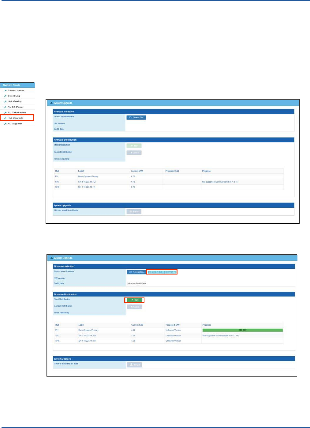
12.2.1. Full System Software Upgrade
Update Firmware
Initial System Setup
You can update firmware for all system elements remotely via the Configuration GUI. This feature
updates Primary Hub and all connected Secondary Hubs and Remote Units. The update file must be
accessible through the software (either locally, on the network, or via USB). You can download the
software from zinwave.com.
To update all hubs:
1.
Click Hub Upgrade from the System Tools menu.
2.
Click Choose File and navigate to the desire file.
The system indicates that it is updating.
After seeing the upload successful message, the Start button is activated.
3.
Click Start to distribute the upgrade files to all of the elements in the system.
This may take some as indicated on screen. A Cancel button is available. Cancelling the activity
loses all progress made up to that point. The status of each file transfer is displayed and after
completion, the Install button is activated.
Installation and Configuration 12-3

Remote Unit Upgrade
Initial System Setup
4.
Click Install.
The update is installed on all Hubs and Remote Units (as required) and all system elements re-start
and execute the newly installed firmware.
12-6 Installation and Configuration
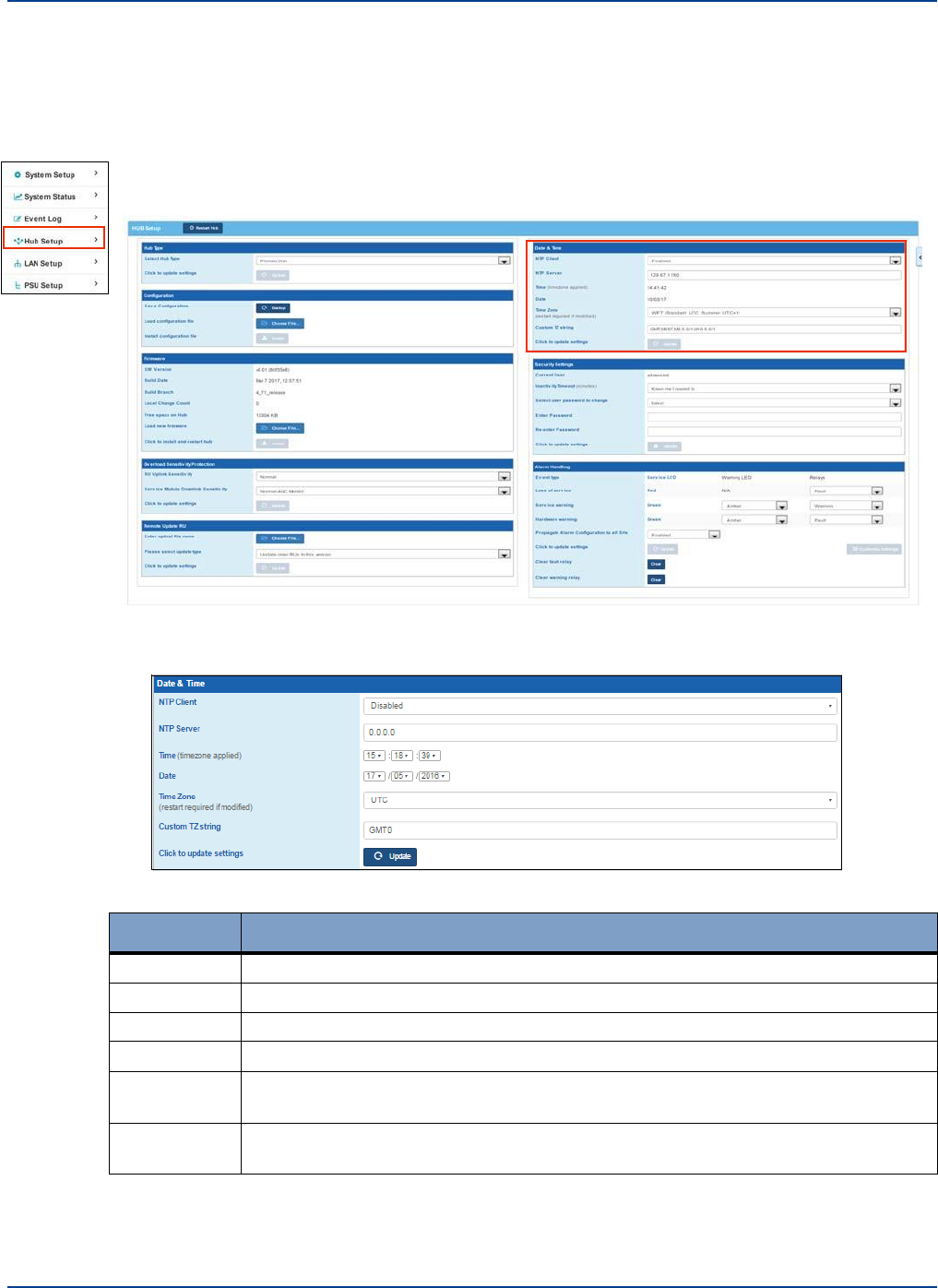
12.3 Setting Primary Hub Date and Time
Setting Hub Date and Time
Initial System Setup
You can set the date and time used for logging events and other data on the Primary Hub. You can
choose to use NTP or to manually enter Data and time information.
1.
Click Hub Setup in the left navigation bar.
2.
Select the desired NTP information or manual entry information.
Type
Description
NTP Client
Enable or disable the NTP client. If enabled. Enter an NTP server IP address.
NTP Server
Enter the IP address of the NTP server, if enabled.
Time
Enter a manual time using the pulldowns. Not needed if using NTP.
Date
Enter a manual date using the pulldowns. Not needed if using NTP.
Time Zone
Select the desired timezone from the pulldown. A Hub restart is required if
selected.
Custom TZ
String
Enter a free text custom time zone string, if desired.
3.
Click Update.
The Hub reboots. You need to log back in to make any additional configuration changes.
Installation and Configuration 12-7
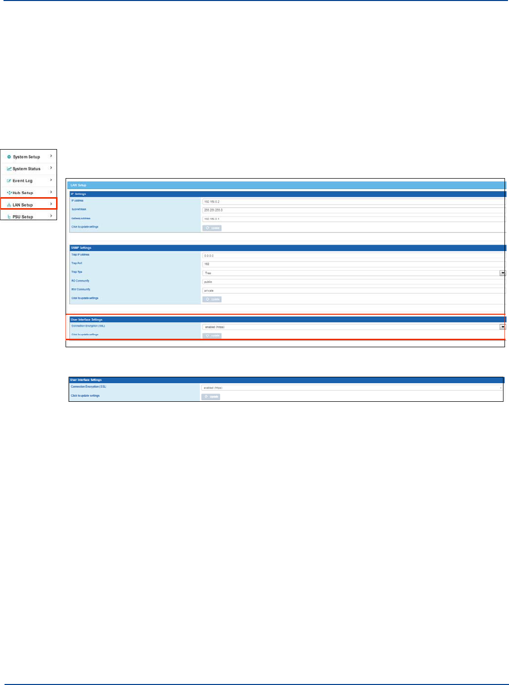
User Interface Settings
Initial System Setup
12.4 User Interface Settings
By default the system uses the standard security technology Transport Layer Security (TLS) for
establishing an encrypted link between a Hub and the browser. This link ensures that all data passed
between the web server and browsers remain private and integral. This is indicated by HTTPS. You
can opt out of the secure connection by changing this setting.
Important: You cannot update Firmware with a non-secure (http) connection. Make sure your
connection is https prior to attempting to upgrade firmware.
To change connection settings:
1.
Click LAN Setup in the left navigation bar.
2.
Select the desired option from the pulldown in the User Interface Settings Pane.
Enable (https) to keep a secure connection or disabled (http) to have an unsecured connection.
3.
Click Update.
After the address is changed, you are logged out and the system reflects the new address in the
address bar.
4.
Log back into the system.
12.5 LAN Settings for Hubs
12.5.1. IP Settings
IP settings are used when you first install a Hub and whenever you want to change an IP address.
To change an IP address for a Hub:
1.
Make an Ethernet connection directly from a PC to the Hub via the Ethernet port on the front of the
Hub.
12-8 Installation and Configuration
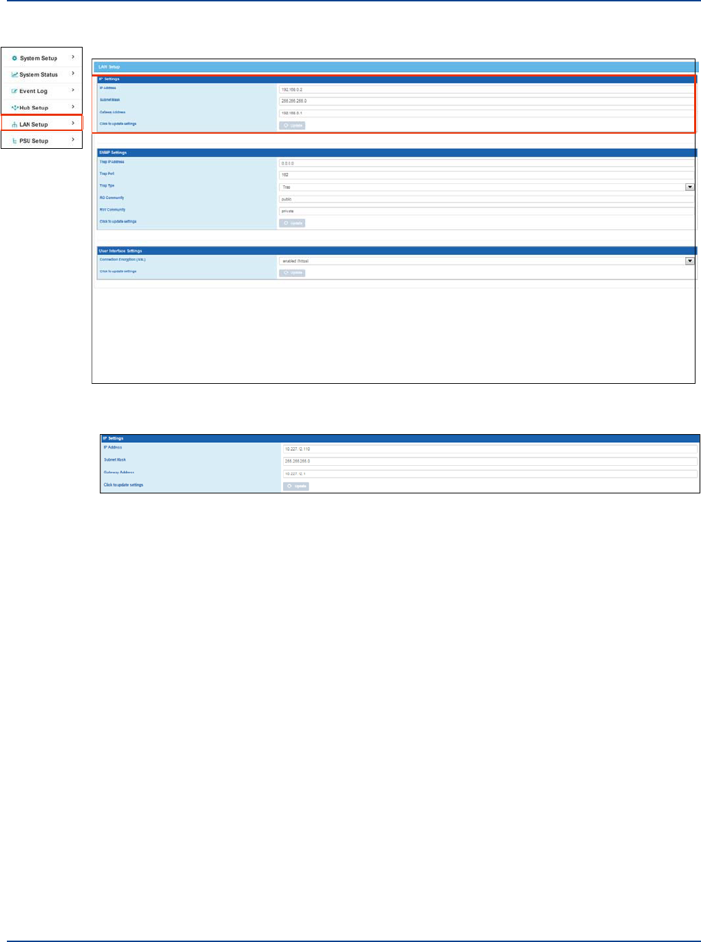
LAN Settings for Hubs
Initial System Setup
2.
Click LAN Setup in the left navigation bar.
3.
Enter the desired IPv4 Address, Subnet Mask, and Gateway Address in the IP Settings pane.
Important: If Hubs are all on the same network, make sure address of individual Hubs are not
duplicated.
4.
Click Update.
After the address is changed access will be lost to the Hub, you must log back into the Hub with its
new address to continue configure. If the IP address is being changed from the network rather
than directly connected to the hub, the new address is populated for you.
5.
Reconfigure your PC network settings in order to access the Hub.
6.
Log back into the system.
Installation and Configuration 12-9
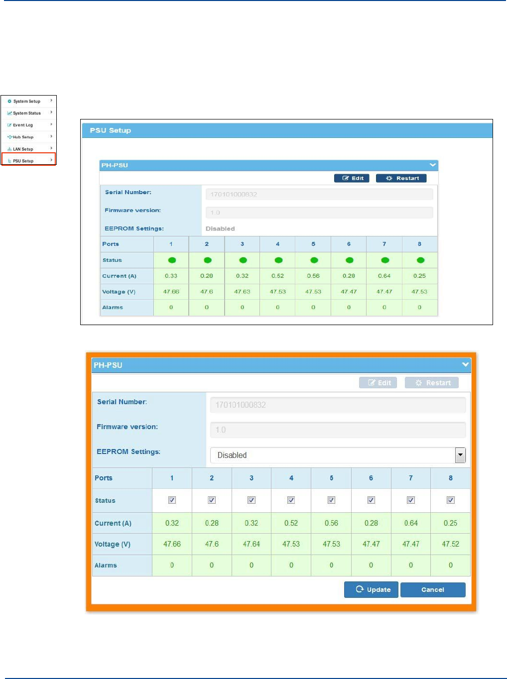
PSU Setup
Initial System Setup
12.6 PSU Setup
After the PSU is physically connected to a hub (see “Connecting the PSU to a Hub” on page 9-4), as
an Advanced user you can turn PSU ports on and off via the software.
To perform PSU setup:
1.
Click PSU Setup from left navigation menu.
2.
Click Edit.
The PSU settings are now editable.
12-10 Installation and Configuration
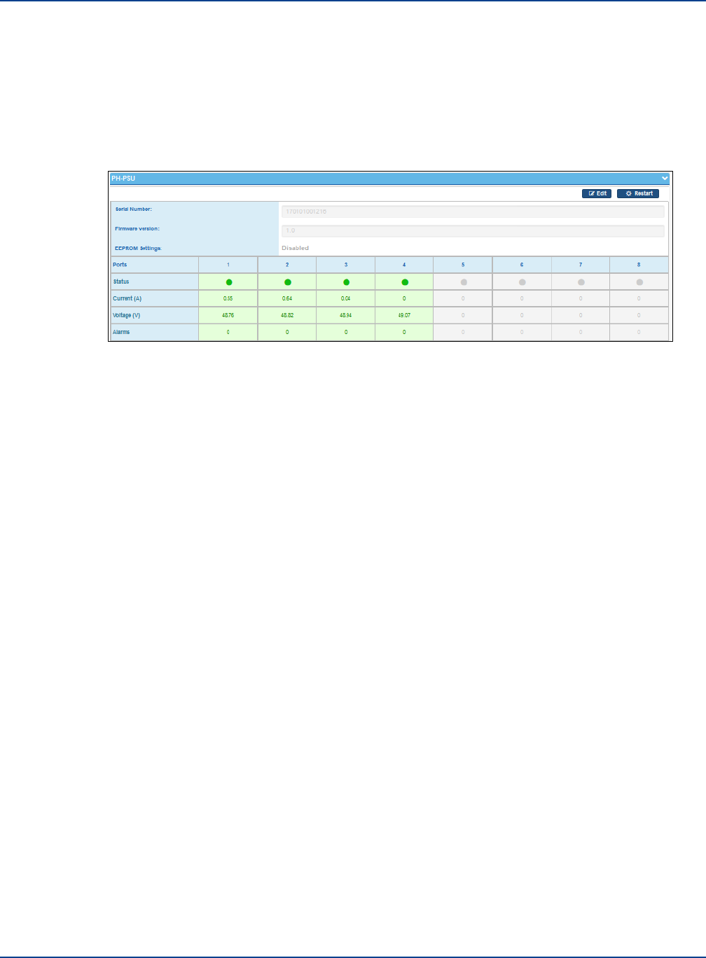
PSU Setup
Initial System Setup
3.
Select the desired EEPROM settings.
EEPROM Settings is disabled by default. Enabling will store the current status of the PSU in
memory and, in the event of a power cycle, the PSU will power on in that same configuration.
4.
Check or unckeck the port checkbox to enable or disable the port.
5.
Click Update.
Enabled ports have a green LED on the equipment and are shown similarly on screen; Disabled
port LEDs are not illuminated on the equipment and are gray on screen.
Installation and Configuration 12-11

PSU Setup
Initial System Setup
12-12 Installation and Configuration
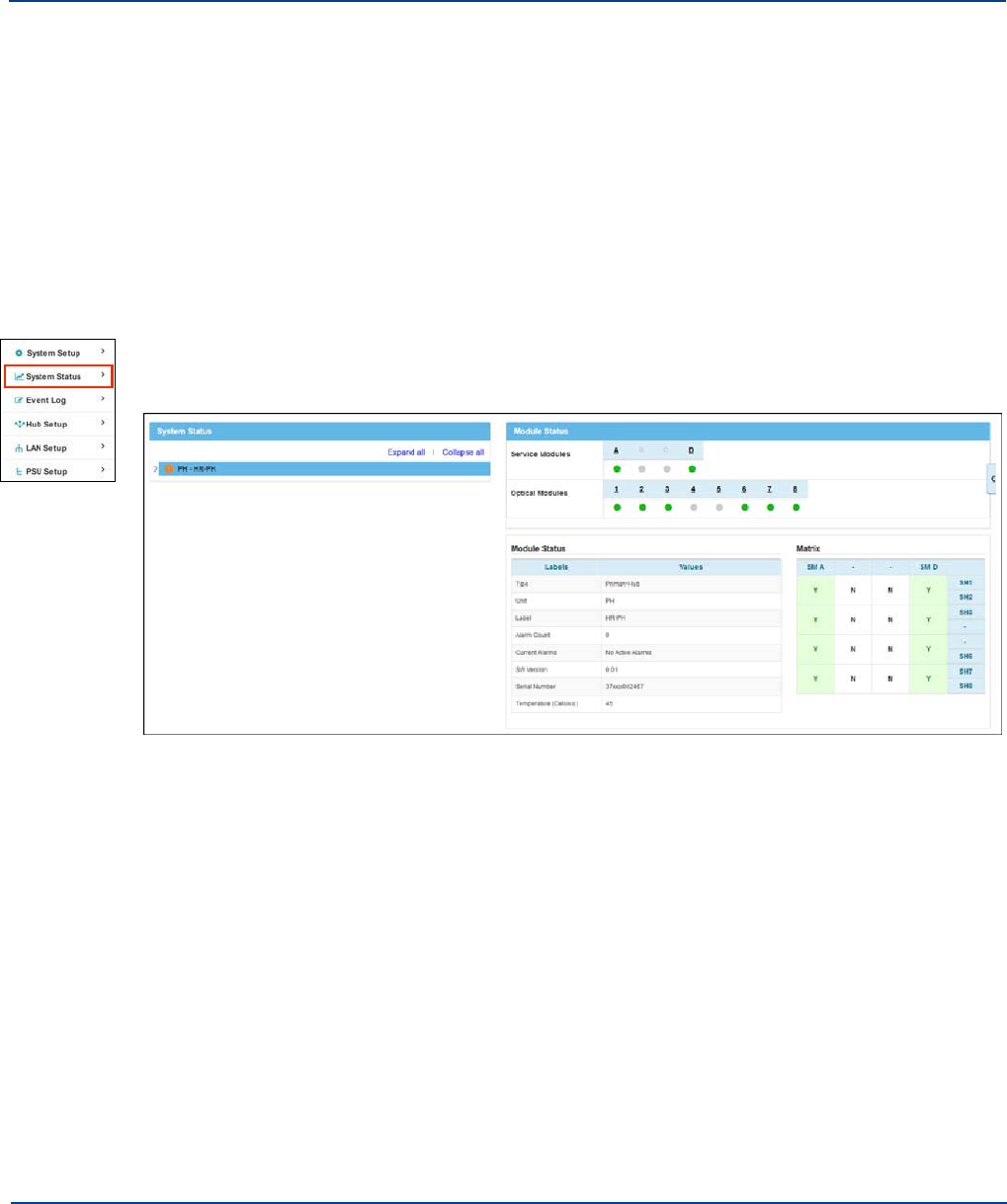
Chapter 13: Understanding System Status
The System Status window is displayed when you first log into the Configuration GUI on a Hub and when
you request it. It provides an overview status of all installed Hubs and Remote Units. This view-only page
provides a tree status of each device and its installed components and connections.
13.1
Viewing System Status
You can view system status when you first log into the Configuration GUI or when you request it via the
left-navigation menu. When viewed from the Primary Hub, the status displays all of the connections from
the Primary Hub through its Secondary Hubs and Remotes. When viewed from a Secondary Hub, all of
the connections to that Hub are shown. The Primary is not shown in this case.
To view system status:
1.
Click System Status in the left-navigation menu.
The System status window is shown.
2.
Click the Primary Hub (PH).
Primary Hub Module Status panes are displayed to the right.
3.
Click the arrow next to the Primary Hub in the System Status pane.
This expands the tree to show details about the Primary Hub and then Secondary Hubs (SH) and
Remote Units (RU) or any Remote Units connected directly to the Primary Hub.
For the Primary Hub Service and Optical Module status panes are displayed to the right, while
Remote Units and Secondary Hubs are shown in the tree.
4.
Click the desired item in the tree.
When you click a Secondary Hub, module status is displayed on the right in a similar fashion to the
Primary Hub.
When you click a Remote Unit, details about the interface and status are displayed. Similarly,
clicking on the arrow to the left of the SH will expand the tree further and show Remote Units
connected to the Secondary Hub.
13-1
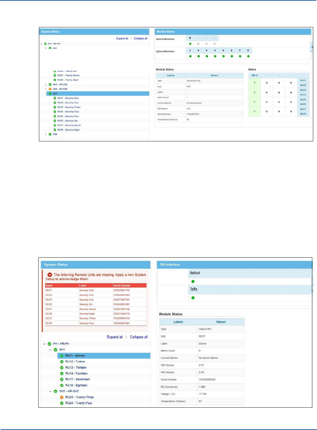
Interpreting System Status
Understanding System Status
Expanding all Secondary Hubs will then provide a simple tree view of the entire system.
For additional System-level status information. See “View System Layout” on page 13-8 and
Download the event log.
13.2
Interpreting System Status
System status is displayed in an expandable and collapsible tree. Colors and symbols are used to
show status. Any alarms are shown at a higher level if the tree is not fully expanded. For example, if
there is a fault on the Remote Unit, it is shown on the Remote Unit when the Remote Unit is visible. If
the Remote Unit is concealed, due to a collapsed view, then the Secondary Hub shows the alarm.
Similarly, if the Secondary Hub is concealed the Primary Hub shows the alarm. In some cases viewing
the system setup shows that there are issues in the system that need to be addressed and fixed prior
to making the system operational. On occasion, a new issue is indicated in this view, alerting that a
problem needs to be corrected.
13-2 Installation and Configuration
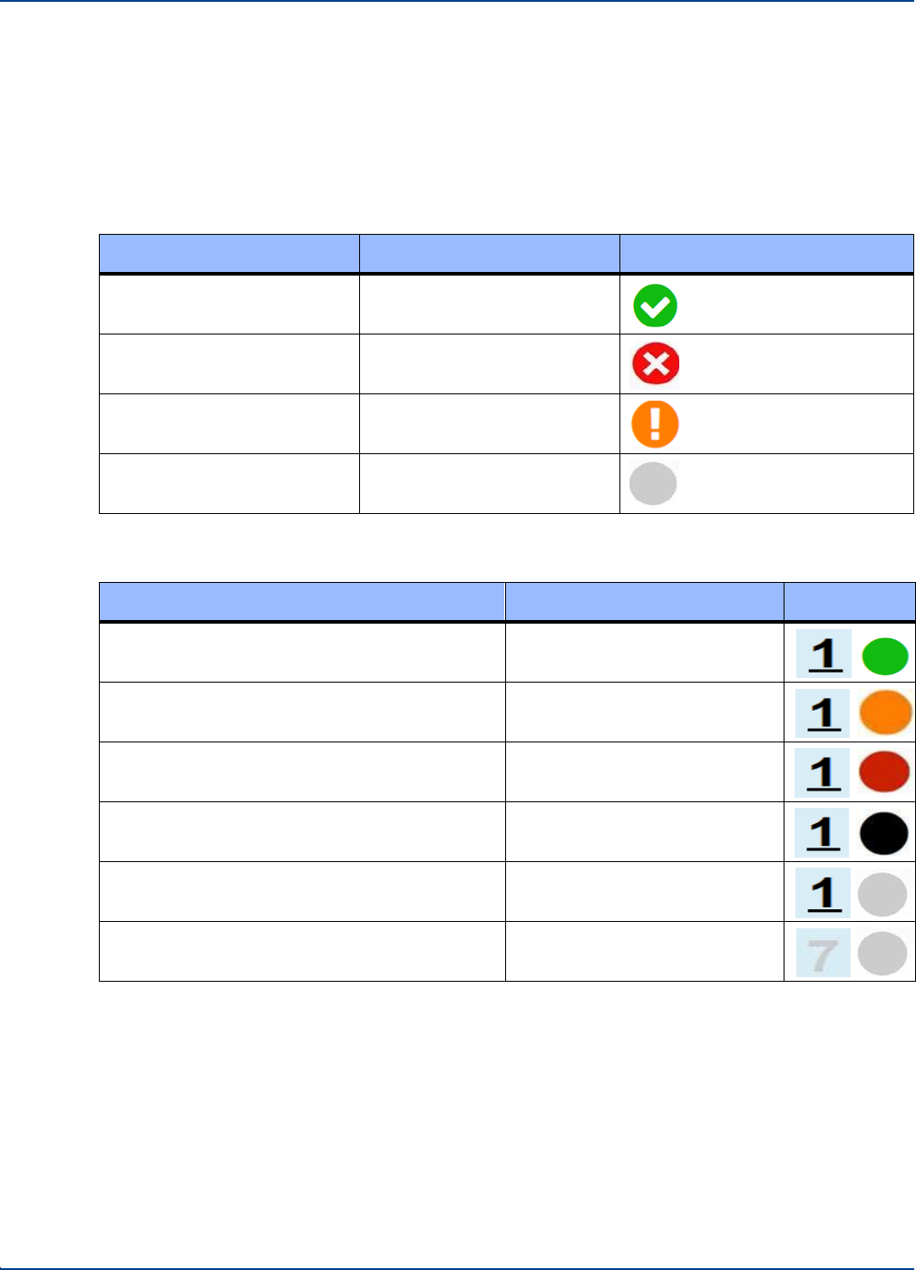
13.2.1. Colors and Symbols
Interpreting System Status
Understanding System Status
Items are displayed throughout the system status screens with color coding and symbology to indicate
status
System Status Topology tree.
Status
Color/Symbol text
Symbol
Good
Green/Checkmark
Trouble
Red/X
Warning
Amber/Exclamation point
Disable by user
Grey dot
Text colors used for Module/Remote Status:
Status
DOT Color/ Symbol Text
Symbol
Module installed and operational
Green/Black Text underlined
Hardware or service warning
Amber/Black Text underlined
Loss of service/fault
Red/Black Text underlined
Disconnected link (to Remote Unit or Optical
Module)
Black/Black Text underlined
Module Installed but disabled (via System
Setup)
Grey/Black Text underlined
Module not installed in the slot
Grey/Grey Text
13.2.2. Hub Status
Both the Primary and Secondary Hubs, provide details about the modules they have installed and the
Matrix of signal routing that has been configured.
Module status is displayed for Service and Optical modules where applicable. Slots A to D in the rear
and 1 to 8 in the front are shown with color coding to indicate module status. Signals are routed from
the Rear to the front. N indicates signal routing along that path. Y indicates that path is active and the
color coding indicates the status of the path.
Installation and Configuration 13-3

Interpreting System Status
Understanding System Status
Module Status details are listed in the on-screen table and described here.
Label
Value Description
Type
The type of unit being viewed.
Unit
The ID of the Unit.
Label
The label of the unit, if entered in System Setup.
Alarm Count
Numbers of alarms on the Hub since the Hub was last power cycled or reset.
Current
Alarms
Details about current alarms.
SW version
The current version of the software.
Serial
Number
The serial number of the unit.
Temperature
(Celsius)
Internal temperature of the unit
13.2.3. Remote Unit Status
When you click Remote Unit in the tree, the status of the Optical and RF interfaces are shown, along
with further details in the table below.
To view Remote Unit Status
1.
Click the Remote unit in the navigation tree.
The status of the Optical and RF interfaces are shown, along with further details in the table below.
2.
Click either the desired Optical Interface or the Desired Tx/Rx interface.
The information displayed in the table below is customized to your selection.
13-4 Installation and Configuration
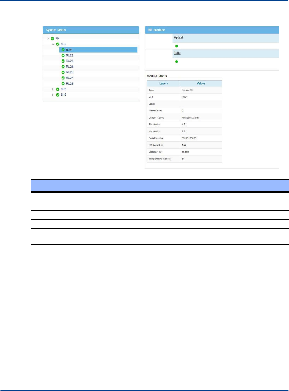
Interpreting System Status
Understanding System Status
When no interfaces are selected, the following table is displayed:
Label
Value Description
Type
The type of unit being viewed.
Unit
The ID of the Unit
Label
The label of the unit, if entered in System Setup.
Alarm Count
Numbers of alarms on the Hub since the Hub was last power cycled or reset.
Current
Alarms
Details about current alarms.
SW version
The current version of the software.
Serial
Number
The serial number of the unit.
HW version
The current version of the hardware.
Temperature
(Celsius)
Internal temperature of the unit.
RU Current
(A)
The Current within the optic part of the Remote Unit.
Voltage 1(V)
The Voltage within the optic part of the Remote Unit.
Installation and Configuration 13-5
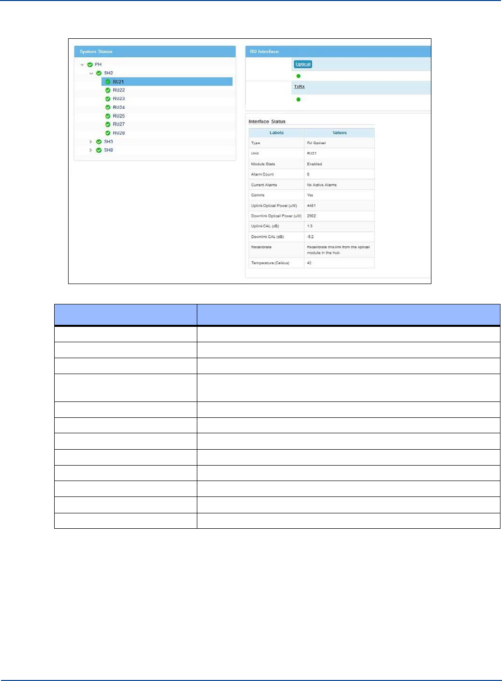
Interpreting System Status
Understanding System Status
When Optical interfaces are selected, the following table is displayed:
Label
Value Description
Type
The type of unit being viewed.
Unit
The ID of the Unit
Module State
Enabled or Disabled
Alarm Count
Numbers of alarms on the Hub since the Hub was last power
cycled or reset.
Current Alarms
Details about current alarms.
Comms
Communication active.
Uplink Optical Power
Uplink power measured in uW.
Temperature (Celsius)
Internal temperature of the unit.
Downlink Optical Power
Downlink power measured in uW.
Uplink CAL
Uplink calibration measured in dB.
Downlink CAL
Downlink calibration measured in dB.
Recalibration
Statement that recommends recalibration if needed.
13-6 Installation and Configuration
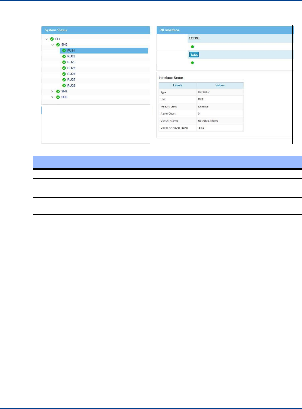
System Tools
Understanding System Status
When TxRx interfaces are selected, the following table is displayed:
Label
Value Description
Type
The type of unit being viewed.
Unit
The ID of the Unit.
Module State
Enabled or Disabled.
Alarm Count
Numbers of alarms on the Hub since the Hub was last power cycled or
reset.
Uplink RF Power
Uplink RF power measured in dBm.
For additional Remote Unit Power information, see “View Remote Unit DC Power” on page 13-10.
For Additional Uplink and Downlink link quality gain and loss information, see “View Link Quality For
Remote Units” on page 13-10. The optical performance of all links ares shown in System Tools section
under Link quality.
13.3 System Tools
The System Tools pane is available on the left side of the application. The tools provide additional
status information for the System as a whole and for Remote Units. System Tools may open in an
additional window or tab, depending on your browser setup. System Layout and Event Log tools are
the minimum set of information you should capture when contacting Zinwave support regarding a
problem.
For information about Hub Upgrade and Remote Upgrade System Tools, see “Update Firmware” on
page 12-1.
Installation and Configuration 13-7
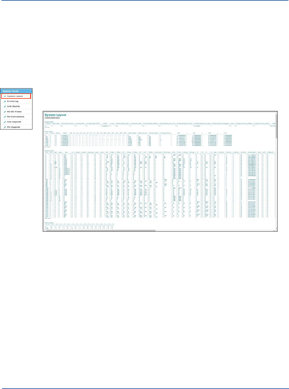
System Tools
Understanding System Status
13.3.1. View System Layout
You can view a complete and detailed system configuration table of system layout status.
Depending on the complexity of your system, this could be quite a bit of information. You can
download the table to a file and then view it other formats, such as an Excel Worksheet.
When selected from a Primary Hub, all the Hubs Secondary Hubs and Remote Units (even those on
Secondary Hubs a) in the installed system are shown. When selected on a Secondary Hub, only the
units attached to that Secondary Hub are shown.
To View System Layout:
1.
Click System Layout in the System Tools menu.
The System Layout window appears.
2.
Scroll to view the table as desired.
3.
If desired, click Download System Layout to save the table to a file.
13-8 Installation and Configuration
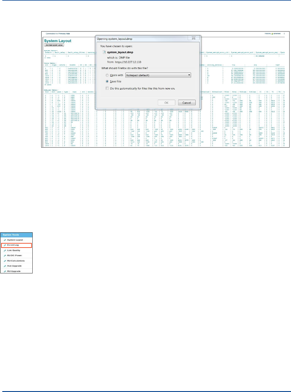
System Tools
Understanding System Status
The file is saved to the default location for your browser. For example, Chrome save is to the
Downloads folder.
The file has a .dmp extensions which Windows may not recognize. You can open the file in a text
editor. See “Interpreting System Layout Tables” on page 17-5 for how to interpret this file. If
requesting help from Zinwave, please have this file up and ready to discuss and/or sent to
Zinwave.
The output can be converted using the latest version of the system layout tool.
(SystemLayout_Gen.xlsm). This file is available on the delivered USB drive and from
zinwave.com.
Note: Using earlier versions may result in occasional spurious layout issues. The latest version is
supplied with the software.
13.3.2. View Event Log
The Log file contains the last 200 events on the system. Depending on the complexity of your system,
this could be quite a bit of information. You can download the table to a file and then view it other
formats, such as a text editor or Word document. See “Event Log” on page 17-3 for information on the
system events.
Installation and Configuration 13-9
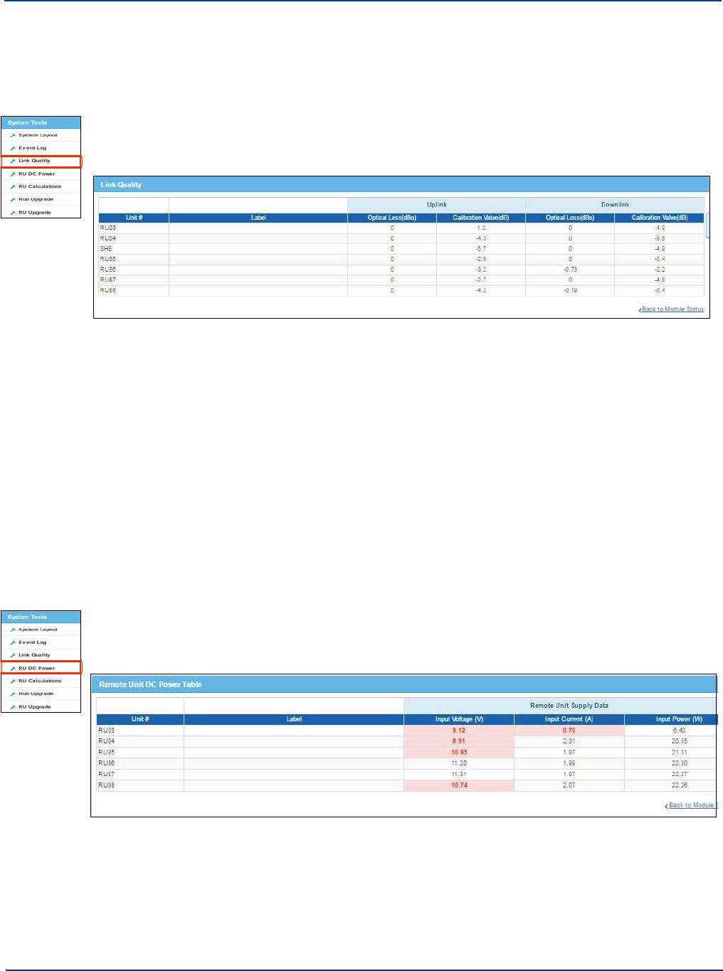
System Tools
Understanding System Status
13.3.3. View Link Quality For Remote Units
You can view the Uplink and Downlink link quality gain and loss for Each Remote Unit.
To view link quality:
1.
Click Link Quality in the System Tools menu.
The Link Quality window appears.
The gain and loss based on the information in System Setup is shown. The values displayed in the
table are the measured optical and RF losses which are used to calibrate the system. These
values are used along with set up information to automatically set correct system values when
Apply is pressed in Edit System Setup.
2.
View the desired values.
Any values which are close to or exceeded the limits of fiber loss are highlighted so that poor
optical links are easily identified. see “Understanding Poor Optical Links” on page 14-4 for more
information.
13.3.4. View Remote Unit DC Power
You can view the details about Remote Units’ DC Power Consumption. If viewed from the Primary Hub
all DC values are shown. If viewed from a Secondary Hub only the DC values of Remotes connected
to the Hub are shown.
To view RU DC Power:
1.
Click RU DC Power in the System Tools menu.
The RU DC Power window appears.
The Input voltages and current are displayed for each Remote Unit along with the overall power
consumption for each Remote Unit.
2.
View the desired values.
13-10 Installation and Configuration
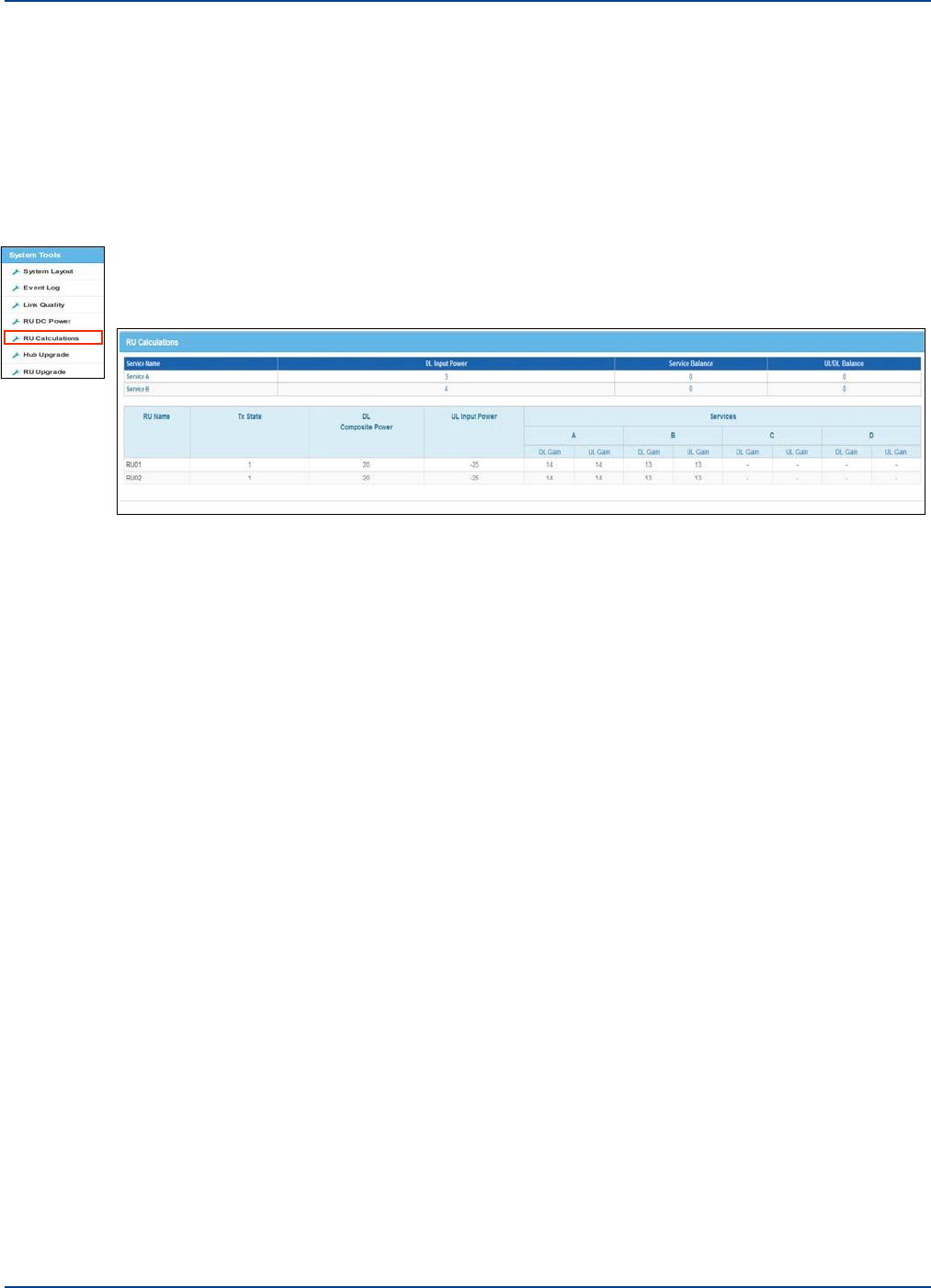
13.3.5. RU Calculations
System Tools
Understanding System Status
The RU Calculations window shows Hub input setup values and for each Remote Unit shows output
power, uplink input power and the gain applied for each system carried by that Remote unit. This data
is also available from the System Layout Tool (Autosetup tab when exported). See “View System
Layout” on page 13-8 for more information.
To view RU calculations:
1.
Click RU Calculations in the System Tools menu.
The RU calculations window appears.
Installation and Configuration 13-11

System Tools
Understanding System Status
13-12
Installation and Configuration
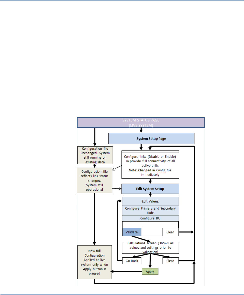
Chapter 14: Understanding System Setup
System Setup provides a baseline for the configured system that is used to set up internal gain stages,
taking into account all fiber connections and self-calibration data.
System Setup is available on a Primary Hub. It is not available on a Secondary Hub. You can configure
all Hubs and Remote Units from this window. The system takes all measure internal values such as
optical loss, together with additional data you input and sets up the system. This additional information is
obtained from RF input measurements and from information calculated using the Coverage Tool.
The base line is used to show any changes that may occur within the system. Addition or removal of
elements can only be confirmed by Applying changes made after editing System Setup.
System Setup consists of two major steps:
1.
Manage individual links within the system by reviewing current System Setup and System Status
Windows. See “Understanding System Status” on page 13-1 for System Status window description
and “Managing Links by Viewing Status” on page 14-2.
2.
Input System Values. See “Inputting System Values” on page 14-5.
An overview flow diagram of the System setup process is shown here.
14-1
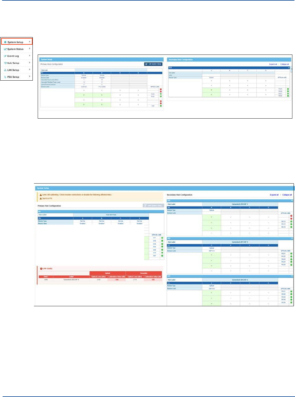
Managing Links by Viewing Status
Understanding System Setup
14.1
Managing Links by Viewing Status
When you access the System Setup page a System Setup summary is displayed. This is similar to the
System Status page; however, it focuses on the signal routing matrix in the Primary and Secondary
Hubs. The items shown are view-only.
The system can only be set up when all links are complete (connected and calibrated and module
LEDS are green). If there are links that are not complete these will be displayed.
To view and fix links:
1.
Click System Setup from the left navigation bar.
The System Setup window is shown with information about links in the System Status pane.
For example, in the capture, incomplete links are shown.
Depending on system configuration, there may be a lot of information on this page. You can
expand and collapse a specific Secondary Hub configuration by clicking the Expand All or
Collapse All links.
2.
Correct Physical links as indicated to get a fully connected system.
If the link has a valid Remote Unit attached you can either wait until calibration is complete or
disable these links and continue. If the cause of incomplete links is due to Remote Units not being
present then the appropriate module in the Hub can be disabled. If no Remote Unit is attached the
link must be disabled for set up to complete.
14-2 Installation and Configuration
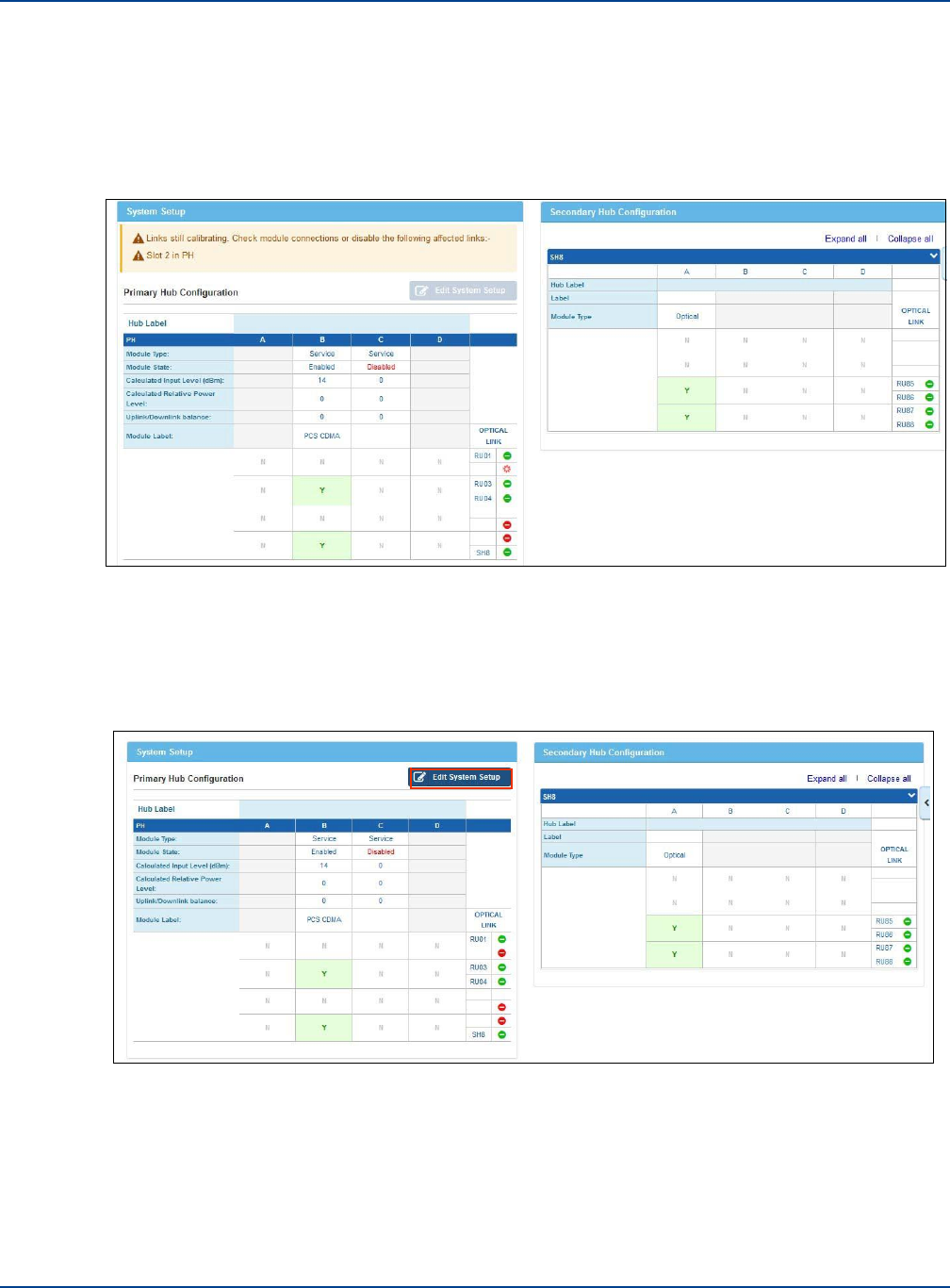
Managing Links by Viewing Status
Understanding System Setup
In the example shown above the issue is caused by slot 6 in the Primary Hub not being able to
connect to the associated Remote Unit (no power at the Remote Unit). See “Understanding Poor
Optical Links” on page 14-4 for more information on Poor Optical Links.
3.
Click on a Green icon to disable the unit, if desired.
While being disabled the icon changes to a spinning red circle. After it is disabled a red Disabled
appears for the item.
When a link is disabled in the GUI, Optical Module itself is disabled and the module’s LEDs appear
dull red.
Any changes made at this stage are implemented immediately allowing you to continue with setup
if parts of the system are still being worked on.
4.
Once all links are corrected, the Edit Setup button turns dark blue allowing you to input system
values. See “Inputting System Values” on page 14-5.
Installation and Configuration 14-3
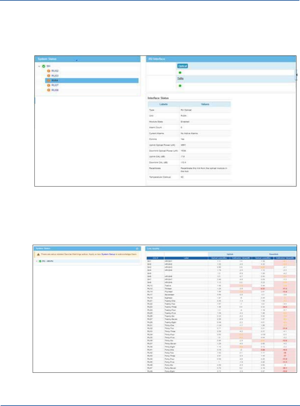
Managing Links by Viewing Status
Understanding System Setup
14.1.1. Understanding Poor Optical Links
The System Status and System Setup windows, indicate a problem on the Remote unit associated
with the poor link. Links that are out of specification are highlighted with an orange exclamation mark in
the System Status tree. You should investigate Link Quality to identify if this is a poor link issue.
You can view the condition of all optical links in the system through the Link Quality System Tool. See
“View Link Quality For Remote Units” on page 13-10 for more information about this feature.
The link quality table displays the optical loss in both the uplink and the downlink and the
corresponding RF loss (Cal value). Where loss exceeds the value that can be corrected in the
hardware, the value is Red. To assist in identifying other issues marginal, links are highlighted in
Yellow.
14-4 Installation and Configuration

Inputting System Values
Understanding System Setup
The condition of each individual link can also be seen through the Optical Interface of the Remote Unit
connected or through optical Module interface of Primary Hub to Secondary Hub links.
Links with high optical loss and calibration values impact system noise (due to optical devices being
overdriven) and the ability of the system to achieve all the desired settings, including Remote Unit
output power. Problems caused by poor optical links are displayed in the System Setup window as
warnings.
Caution: While the system can be configured with poor links present, this will affect the
system performance and such links should be examined and brought into specification in
order to obtain optimum performance.
A poor link may affect connectivity of the system. Set up can only be run with a fully connected and
stable system. When links have very high loss they often drop connections to the far end resulting in
instability during the set up process. When a change in link status occurs during set up, the process
will fail. Links with very high loss or bad calibration should be disabled via the System Setup window
until corrected or addressed by cleaning and checking optical connections to allow for a smooth set up
completion.
14.2
Inputting System Values
You can edit items already physically connected to the system and their links have been verified.See
“Managing Links by Viewing Status” on page 14-2 above to manage links. Hardware must be installed
and initially configured to proceed with System Setup. To add new hardware to the system, follow the
instruction in “Changing or Swapping Equipment” on page 14-14. After all new connections are added,
return to this screen to edit settings for the new devices.
To Edit system values:
1.
Make sure all system links are corrected. See “Managing Links by Viewing Status” on page 14-2.
2.
Click System Setup from the left navigation bar.
3.
Click Edit System Setup.
The system layout is shown as when you click the System Setup link from the left navigation bar;
however, the items are now editable. The Primary Hub with service inputs is on the right side of the
page. Secondary Hubs are shown on the left with Remote Unit configuration below the Secondary
Hubs.
For each hub, the matrix settings are displayed giving a visible indication of how services are
mapped through to Remote Units.
The discovered Service Modules are shown at the top of the matrix with Optical Modules
connecting to Secondary Hub and Remote Units shown on the right of the matrix.
Installation and Configuration 14-5
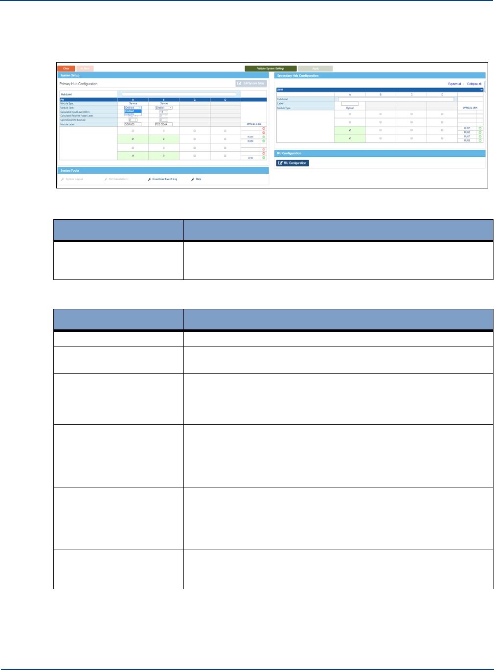
Inputting System Values
Understanding System Setup
Note: Service Modules, although present, do not have to be used. Service Modules in use should be
marked as enabled. If no service is connected then these inputs should be marked as
“disabled” so that the systems can calculate gains settings correctly.
4.
Edit the Hub label for the Primary Hub.
Value
Description
Hub Label
The name of the Hub. Free text field. 20 character limit. Special
characters such as & and %. are not allowed; however, space and
underscore are allowed.
5.
Enter the following information for each enabled service module.
Value
Description
Module Type
The type of Module (not editable).
Module State
Enabled or Disabled. Select disable if the Modules are inserted but
service is not connected.
Calculated input level
(dBm)
Measured composite power level delivered to the module from the
Signal source. Select the numeric value from the pulldown. For more
information on how to calculate the values, see “Calculated Input
Level” on page 14-12. This a required field.
Calculated Relative Power
level
Reflects the principles of composite power based on the number of
services and channels for each service required to give uniform
service coverage. Select the numeric value from the pulldown.These
values are supplied to you and have been calculated using the
Coverage Tool.
Uplink/Downlink Balance
Allows for variation in transmit and receive path directions depending
upon system requirements. Select the numeric value from the
pulldown (+10 and -10). For more information on how to calculate the
values, see “System Uplink/Downlink Balance” on page 14-11. This a
required field.
Module Label
Name of a module. Free text field. 20 character limit. Special
characters such as & and %. are not allowed; however, space and
underscore are allowed.
6.
Check the desired boxes at the intersection of inputs and outputs.
14-6 Installation and Configuration
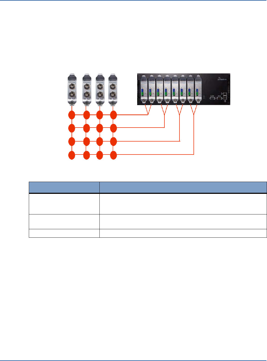
Inputting System Values
Understanding System Setup
Boxes should be green indicating good routing status.The Hub features a unique internal service
distribution matrix that provides flexibility in terms of how supported wireless services are routed
within a system deployment. This means specific operators or frequencies can be routed to the
entire system or to designated sections of the system, depending on requirements.
When clicked the path is enabled. No check indicates that the path is closed and no signals will
pass.
Note that if the matrix is not enabled correctly then a warning will appear during the setup process
as without a complete path from service mode to remote unit appropriate internal setting cannot be
made.
7.
Edit the desired values for Secondary Hubs.
Value
Description
Hub Label
The name of the Hub. Free text field. 20 character limit. Special
characters such as & and %. are not allowed.:However, space and
underscore are allowed.
Label
Free text field. 13 character limit. Special characters such as & and
%. are not allowed.; however, space and underscore are allowed.
Module Type
The type of Module (not editable).
Note: Hub types are assigned on the Hub Status page. See “Setting the Hub Type” on page 12-1.
Note: It is not possible to disable the input to the Secondary Hub as this would disconnect the
Secondary Hub and make reconnection impossible.
8.
Check the desired boxes to activate the signal routing matrix items.
Boxes should be green indicating good routing status.
Installation and Configuration 14-7
X
X X X
X
X X X
X
X X X
X
X X X
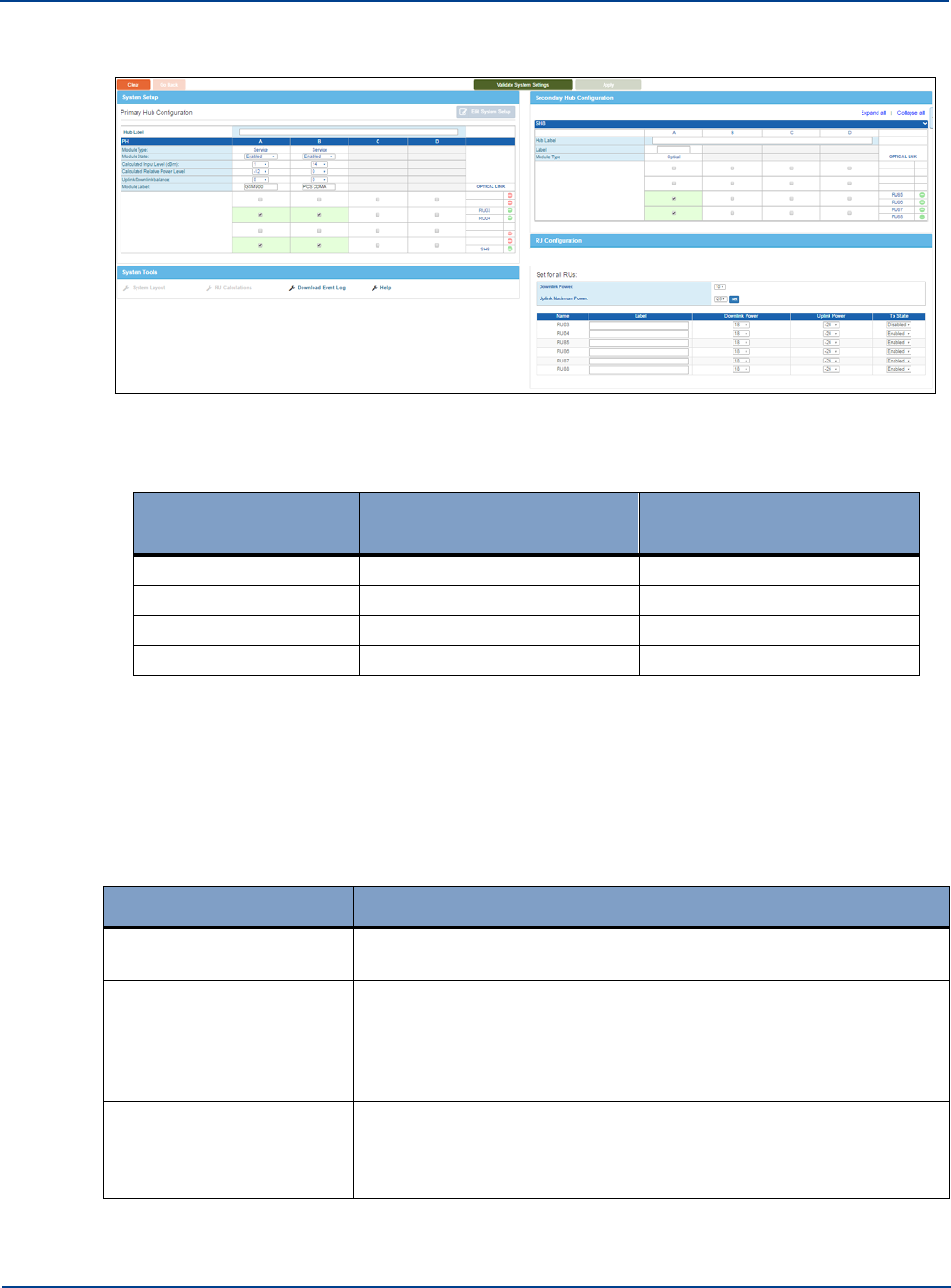
Inputting System Values
Understanding System Setup
The status for Remote Units is shown.
Remote Units are automatically assigned a number based on their position in the system. The
number is based on the Primary Optical Module port number to which the Secondary Hub is
attached (if any) and the port to which the Remote Unit is attached. For example,
Remote Unit Number
Primary Hub to Secondary
Hub
Remote Unit Connection
RU31
3
1
RU32
3
2
RU33
3
3
RU04
No Secondary Hub
4
9.
Enter the Downlink Power and Uplink Maximum Power for all Remote Units by selecting values
from the pulldowns.
See“Remote Unit Downlink Power” on page 14-13 and “Remote Unit Uplink Power Max” on page
14-14 for more information on calculating these values.
10.
Click Set.
11.
If these values apply to all Remote Units, skip to step 14.
12.
Edit the desired values for the Individual Remote Units.
Value
Description
Label
The name of the Remote Unit. Free text field. Space and underscore
are allowed.
Downlink Power
Downlink output power defines the geographic coverage of the
Remote Unit in conjunction with the connected antenna. Select the
numeric value from the pulldown. Default value is -10dBm. For more
information on how to calculate the values, see “Remote Unit
Downlink Power” on page 14-13.
Uplink Power
Influences a number of parameters including Uplink Gain and Noise.
Select the numeric value from the pulldown. The default value is -
25dBm. For more information on how to calculate the values, see
“Remote Unit Uplink Power Max” on page 14-14.
14-8 Installation and Configuration
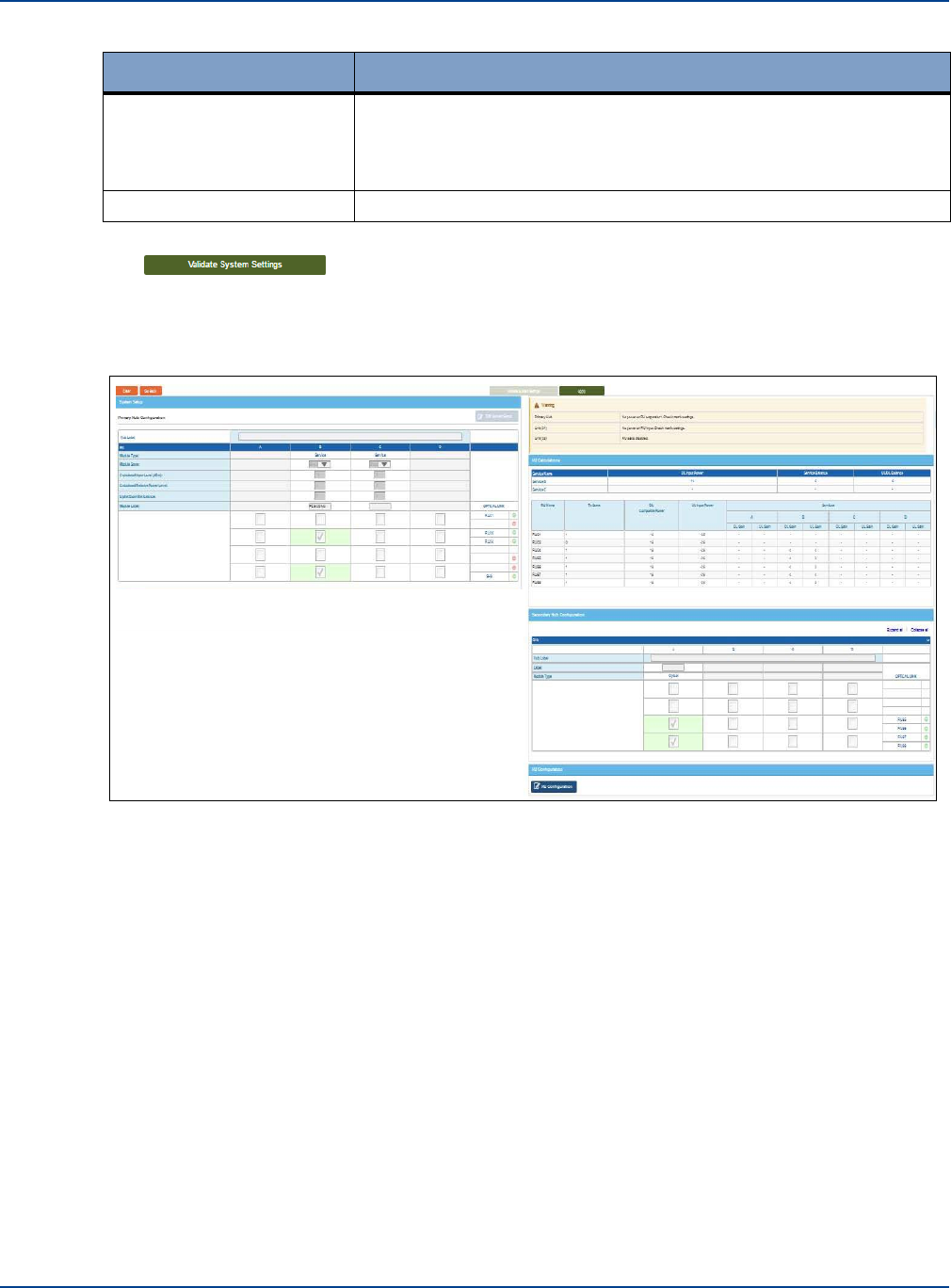
Inputting System Values
Understanding System Setup
Value
Description
Tx State
Enabled or Disabled. Disabled switches off the final stage power
amplifier in transmit path (downlink direction) and the first low noise
amplifier in receive path (uplink direction). Will remove service from
areas covered by that particular. Default is Enabled.
Module Label
Name of a module. Free text field.
13.
Click Validate System Settings.
The system takes some time to calculate the inputted settings and validate them. A progress
indicator is shown. It then returns with a screen similar to the initial status screen. It is not editable,
however, it displays any warnings, errors, or link issues with system setup and the Apply button
becomes active (dark).
Installation and Configuration 14-9
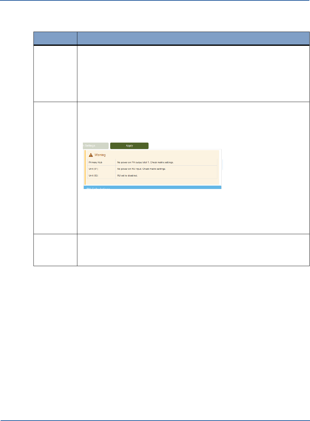
Inputting System Values
Understanding System Setup
Notification
Description
Link Error
Shows optical links that are connected (allowing Setup to be completed) but where
the measured optical or RF link performance across a fiber is greater than the
maximum value that can be corrected by the hardware. These links are shown on
the System Setup page and reported in Link Issues after validation.
Links with issues impact noise (due to optical devices being overdriven) and ability
to achieve desired Remote Unit output powers. Links issues should be addressed
by cleaning and checking the optical links affected units.
Warnings
Warnings are used to indicate anomalies within the system that can be due to
configuration errors or conflicts. These are not fatal but should be examined and
assessed. These warnings are typically due to poor optical links with excessive
loss, which means that desired output power cannot be achieved, or that matrix
settings are not applied. In this example,
there is a warning that the matrix has been set incorrectly on the Primary Hub
resulting in no through RF path. This means that correct gains cannot be set and
incorrect values used in the configuration
In addition there is a warning that one of the Remote Units has been set to
disabled.
Errors
These are fatal errors in the Setup process which prevent validation and Setup from
completing. If an error is encountered, go back and check loaded values or optical
link performance. The most common source of errors is due to the presence of un-
calibrated optical links.
14.
If you wish to modify the system settings due to warnings that were displayed, click Go Back to
return to the applied settings and make changes or Clear to empty all inputted settings.
The system performs on-going monitoring and self-checking process for the system topology. It
automatically checks for the presence of Remote Units and Modules and the calibration state of all
links. If anything is connected or removed from the baseline configuration, it is indicated on the
System Status window. System Setup needs to be performed and validated to activate these
changes.
15.
When you are satisfied with the configuration, click Apply.
The system applies all the input and output requirements to the internally calculated calibration
measurements for each link. Together these are applied to the various gain blocks throughout the
system to achieve the desired settings. This is carried out in line with a set of predefined set points
designed to minimize noise result in gain settings for individual components.
The system continually monitors and checks the system topology.
Alarms and warning displayed on both Status and Setup pages
Note: All changes must be validated and applied.
16.
If changes are required, repeat this procedure to input, validate, and apply them.
14-10 Installation and Configuration

14.3
System Uplink/Downlink Balance
System Uplink/Downlink Balance
Understanding System Setup
The uplink/downlink balance allows for variation in transmit and receive path directions depending
upon system requirements.
With the uplink downlink balance at its default values of 0 the uplink and downlink gains are the set to
the same value. A setting of 5 will request and uplink gain of 5dB higher than the downlink gain.
Similarly, a setting of -5db will set the uplink gain at 5dB lower than the downlink.
Note: The maximum gain of the system is 25dB. If levels set in the system require greater gain, then
Setup will not be possible.
The maximum system gain that can be set in either uplink or downlink directions is 25dB. The actual
gain is set by many combinations of input, output and balance parameters.
The gain is primarily defined in the Downlink. The downlink gain, before service balancing, is
determined by the Calculated Input Level and the Remote Unit Downlink power. For example to
achieve a maximum downlink gain of 25dB with a maximum output level set at +18dBm the minimum
input level that can be set is -7dB when a single service port is enabled. When the Uplink Downlink
balance is set to 0dB, the system will try and set the uplink to the same value as the downlink gain.
However, the Uplink gain is also bound by the Uplink Power max setting on the Remote Unit and the
target output level of the Service Module in the uplink direction. The target output value of the Service
module is only -10dBm. Thus, if the downlink gain is set for maximum gain the Uplink Power max must
therefore be set to -35dBm or lower if the uplink and downlink gains are to be equal.
Input level -7dBm
Maximum Output level +18dBm
-
Downlink Gain = 25dB
With Uplink / Downlink balance set to 0
Uplink target = 25dB
Maximum output level (not configurable) =-10dBm
-
Uplink power max must be set to -35dBm to achieve uplink gain
If the balance is set to 0dB but the Uplink max power is set to -25dBm then the uplink gain will be
limited.
Input level -7dBm
Maximum Output level +18dBm
-
Downlink Gain = 25dB
With Uplink / Downlink balance set to 0
Uplink target = 25dB
Maximum output level (not configurable) =-10dBm
Uplink power max set to -25dBm
-
Uplink gain = 15dB
If the Uplink / Downlink balance is set to -10 the uplink gain target will be set 10dB lower than the
downlink.
Installation and Configuration 14-11

Calculated Input Level
Understanding System Setup
Input level -7dBm
Maximum Output level +18dBm
-
Downlink Gain = 25dB
With Uplink / Downlink balance set to -10
(Uplink target = 15dB)
Maximum output level (not configurable) =-10dBm
-
Uplink power max must be set to -25dBm. Note if the Uplink power max is set to less than -
25dBm the noise figure will be improved but uplink gain will still be limited to 15dB due to setting of
Uplink/ Downlink balance.
It is important to note that the System performs a gain self-calibration process when links are
established using internally generated signals and measurement circuits. The self-calibration is
designed to optimize the system gain settings for the required downlink output power and to minimize
uplink noise figure for the required maximum input signal. To achieve these minimum noise figures
there are a number of set points within the system which must also be achieved.
When setting the uplink maximum power, there are two key parameters to consider: noise and largest
expected uplink input signal. The minimum uplink noise figure is achieved with the lowest uplink
maximum power and the largest uplink gain. However, this will provide the least protection against
uplink input signals, including any noise coupled from the downlink. In systems where Uplink noise is
critical, such as UMTS, care must be taken to ensure that the SNR ratio in the uplink is maintained.
The Zinwave coverage tool can be used to calculate appropriate levels.
The system up and down link gains are displayed during the Auto Setup process for each service input
for each Remote Unit.
14.4
Calculated Input Level
The Calculated input level is the measured composite power level delivered to the module from the
Signal source (BTS BDA etc.) with a frequency compensation factor to take into account the typical
frequency response of the system. The total composite input power level should not exceed +15dBm
Care must be taken to ensure that the setting reflects the total power possible at the SM. It is important
to know not only what is currently connected and being measured, but also what will be connected.
Particular care should be taken when using CDMA signals where the initial power measured is often
that of the Pilot and not the maximum transmit power. Similarly, with cellular services, initial
measurements often do not show all traffic channels which will only be operational under loaded
conditions.
14-12
Installation and Configuration
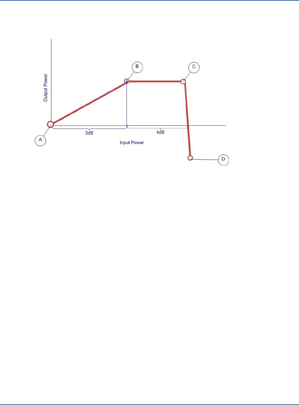
Remote Unit Downlink Power
Understanding System Setup
It should be noted that the input level is alarmed to detect and protect the equipment from inadvertent
or accidental overload of the incoming composite power. The performance of the overload protection is
shown below
•
A is the “calculated input level”.
•
In region A-B (0 to 3dB above the set input level) the corresponding output power will increase
by the same level.
•
In region B-C (4-7dB above the “calculated input level”), the power will be limited at the same
level by switching in attenuation on the SM.
•
In region C-D (greater than 7dB above the “calculated input level”), additional attenuation will
be switched on, effectively shutting services connected to that input to the PH.
Other services will be unaffected.
14.5
Remote Unit Downlink Power
This value will be determined by the system design. The downlink output power defines the
geographic coverage of the Remote Unit in conjunction with the connected antenna.
Notes on Remote Unit power:
•
The maximum composite output power for all Services is a regulatory requirement and will
vary depending upon where the UNItivity 5000 Platform is being deployed
•
In CE Territories the Output power is limited to +18dBm
•
In the USA where FCC regulations apply the maximum composite power can be +20dBm
The maximum EIRP is +20dBm for WLAN in Europe and +28dBm for all approved services in USA &
Canada. This corresponds to antenna gains (including any cable and splitter losses) of 2dBi for WLAN
in Europe and 8dBi for USA & Canada.
Installation and Configuration 14-13

Remote Unit Uplink Power Max
Understanding System Setup
14.6
Remote Unit Uplink Power Max
The uplink power max influences a number of parameters including Uplink Gain and Noise.
The default value is -25dBm.
When setting the uplink maximum power there are two key parameters to consider: noise and largest
expected uplink input signal. The minimum uplink noise figure is achieved with the lowest uplink
maximum power and the largest uplink gain. However, this will provide the least protection against
uplink input signals, including any noise coupled from the downlink. In systems where Uplink noise is
critical such as UMTS care must be taken to ensure that the SNR ratio in the uplink is maintained. The
Zinwave coverage tool can be used to calculate appropriate levels.
The uplink sensitivity is measured at the Remote Unit and it is generally assumed that there is no loss
between the Remote Unit and the antenna. If there is additional loss, due to either additional cable loss
or filtering, this can change the sensitivity setting (if desired) as it may increase isolation between Tx
and Rx paths.
The impact of the inclusion of additional loss, in terms of sensitivity, can be seen in the coverage tool
by changing the value “Isolation Measurement Adjustment” in the UL sheet.
The value set for Uplink Power max is also protected to prevent damage in the presence of large
unwanted signals. The method of protection is the same as the service input settings. 3dB above the
value will result in a corresponding increase in signal output at the Primary Hub output but beyond this
AGC will be applied and at 7dB the Remote Unit input will be shut down.
14.7
Changing or Swapping Equipment
If equipment is removed from an existing system, the system will recalibrate links and apply stored
configuration settings. This will be shown in System Setup with a message like, “The following remote
units are missing. Apply a new system setup to acknowledge them”. This is because the system has
changed from the “baseline" configuration set up after the Apply button was pressed.
Do not make any equipment changes while the system is validating its set up as this will invalidate any
System Setup process and the setup will fail. A message will be displayed indicating the failure and
request that you restart system set up. If this happens, rerun the system setup and validation after
equipment has been added or removed.
14.7.1. Hub
If a Hub is disconnected from the system due to failure of power or optical link, for example, when the
same unit is reconnected it will resume its defined configuration. If a different unit is installed in its
place, the new unit will have factory default configuration (unless previously configured elsewhere) and
must be changed through the Hub Setup page and by re-running the System Setup process to set the
correct matrix configuration.
14-14 Installation and Configuration

14.7.2. Remote Unit
Changing or Swapping Equipment
Understanding System Setup
If a Remote Unit is disconnected from the system, when the same unit is reconnected to the same
optical module the, the system recalibrates the links and applies the stored settings. If a different unit is
reconnected, the system sets the unit to its default condition. Edit the system settings to input custom
values.
14.7.3. Optical Module
If a link is broken either due to fault or intervention the system automatically recalibrates the link and
applies the appropriate gains when the system is restored even if a different unit is swapped in to the
system.
Installation and Configuration 14-15

Changing or Swapping Equipment
Understanding System Setup
14-16 Installation and Configuration
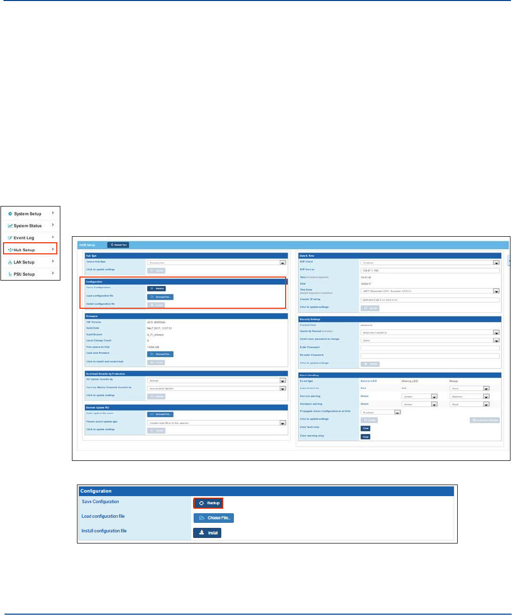
Chapter 15: Understanding Hub Setup
While System setup configures how the system works together, Hub setup configures the individual
Primary and Secondary Hubs. These functions are needed for initial hardware installation as well as
ongoing updates.
15.1
Configuration Files
Once the system has been set up the Hub configuration can be saved. This can provide a restore facility
if the system has to be backed up to an earlier version of configuration. The config file (.cfg) includes IP
address information, matrix settings and Remote Unit settings for a Hub. You cannot use a single config
file for multiple Primary Hubs or Secondary Hubs. The config file for each unit should be saved with a
unique file name.
It is recommended that when system set up is complete the configuration file is saved.
To save a Hub configuration:
1.
Click Hub Setup in the left navigation bar.
2.
In the Configuration pane, click Backup.
Depending on your browser, the file is saved to your computer’s file system. For example Chrome
places it in a Downloads folder.
3.
Navigate to the saved file and rename it to the Hub label set in System Setup.
15-1
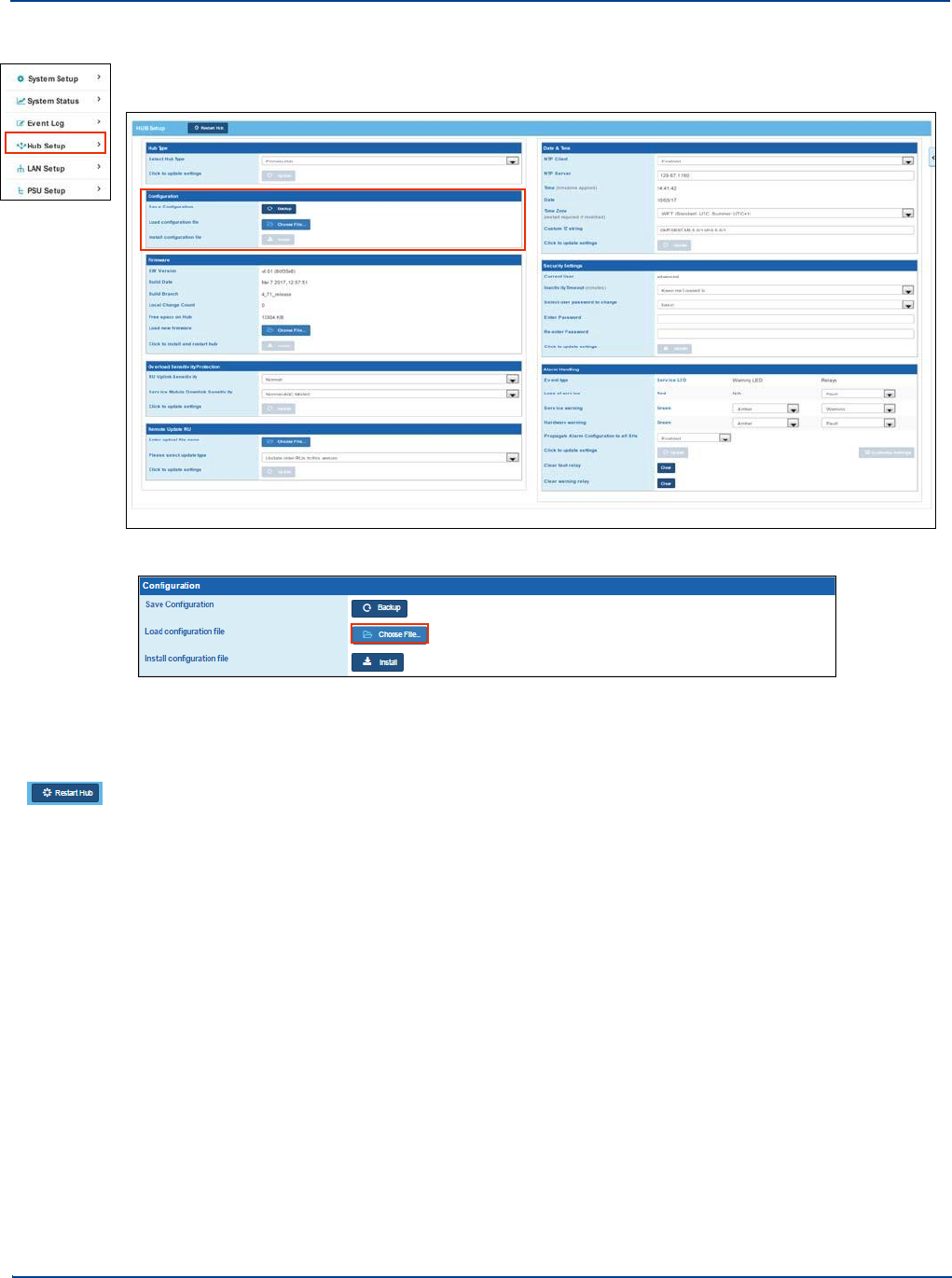
Configuration Files
Understanding Hub Setup
To load a Configuration File:
1.
Click Hub Setup in the left navigation bar.
2.
In the Configuration pane, click Choose File.
3.
Navigate to the desired configuration file and select it.
4.
Click Open.
5.
Click Install.
6. Click Restart Hub at the top of the window.
15-2 Installation and Configuration
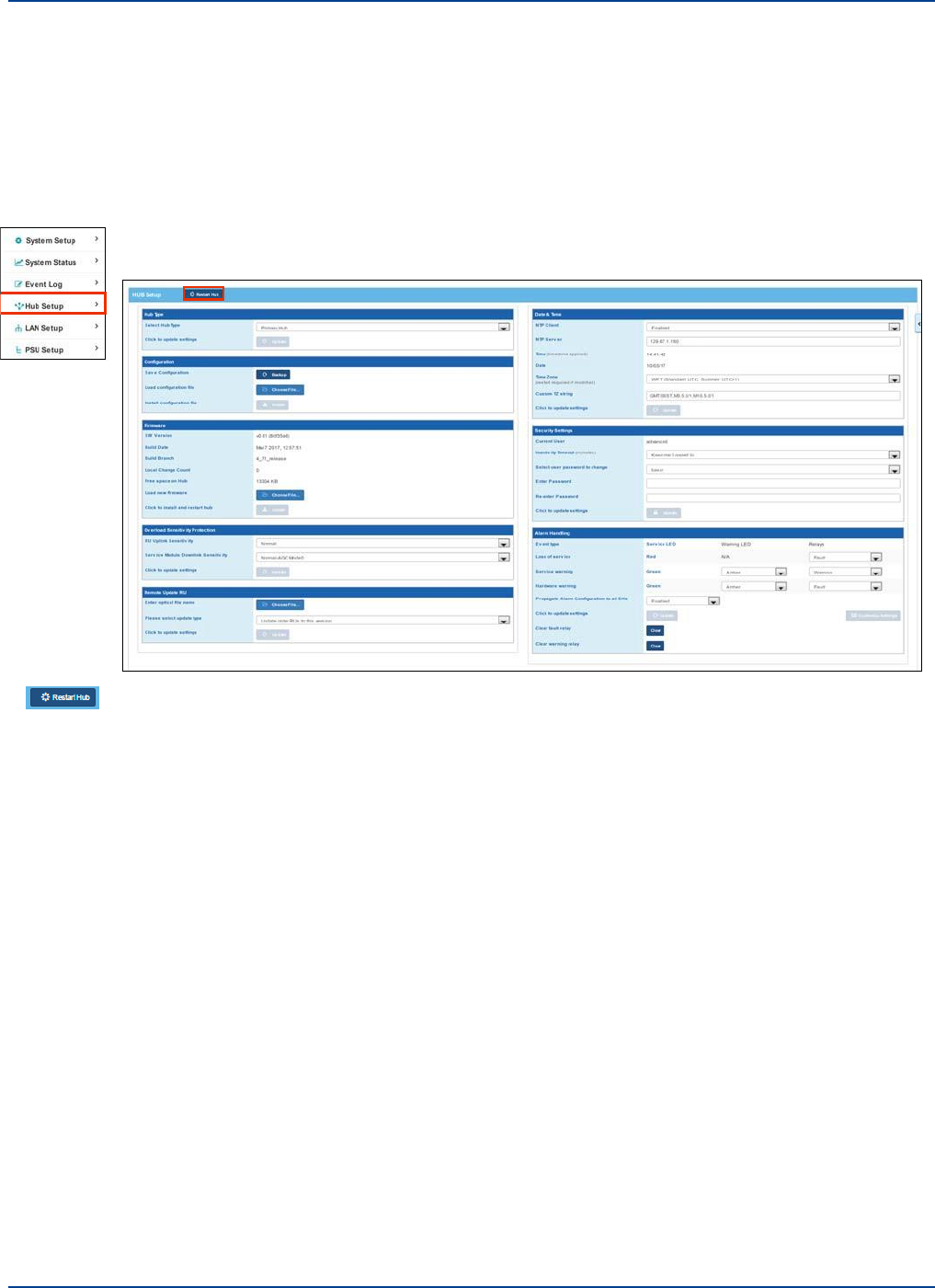
15.2
Restarting the Primary Hub
Restarting the Hub
Understanding Hub Setup
A hub will restart under certain conditions such as changing time zone and updating software.
However, the function of this button is to provide a software restart. It should not be used unless a
forced restart for the system is required or suggested by Zinwave support staff.
To restart a Hub:
1.
Click Hub Setup in the left navigation bar.
2. At the top of the page, click Restart Hub.
15.3
Factory Reset of a Primary Hub
It may be necessary when redeploying or reconfiguring equipment to set the Hub back to factory
default values.
The reset button can be found behind the small hole located to the left of the Alarm Serial interface. If
an installation was interrupted or if there has been a catastrophic issue with a Hub that cannot be
recovered, you can return the Hub to factory settings. This requires a physical reset to the system.
Installation and Configuration 15-3
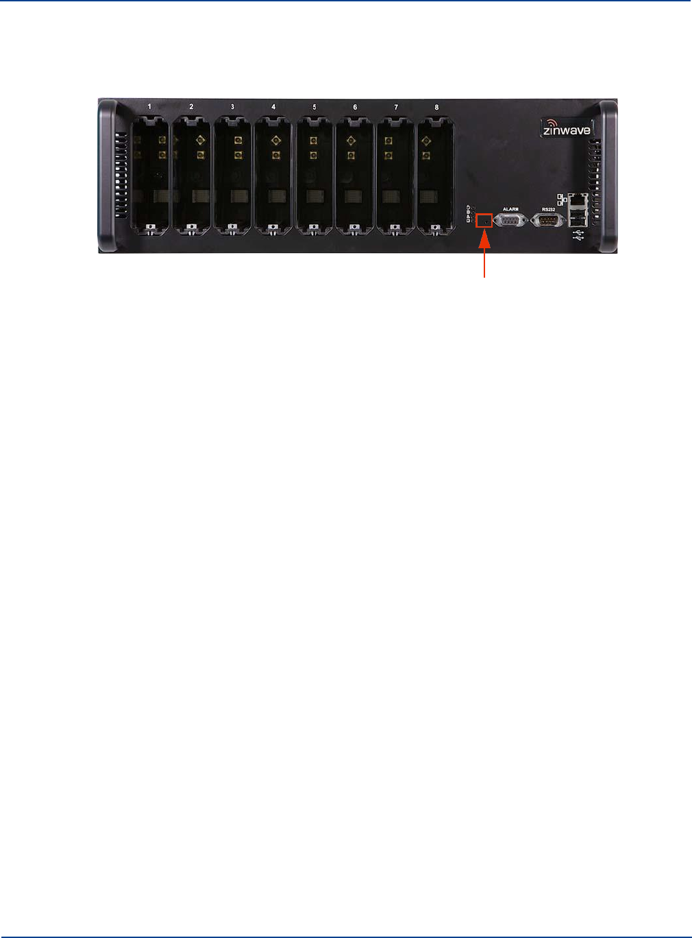
Factory Reset of a Hub
Understanding Hub Setup
To reset a Hub to factory settings:
1.
Using a small device (such as an open paper clip), push the Reset button located on the front of
the Hub and hold in for 5 seconds.
You need to insert the tip of the device into the hole as the button is set in from the front face.
The Hub restarts and the LEDS flash. The Hub is returned to the default IP address and
configuration settings:
•
IP Address: default 192.168.0.2
•
Sub Net: Default 255.255.255.0
•
Gateway: Default 192.168.0.1
•
Passwords: Advanced: supervisor
•
NTP Settings: default disabled
•
Alarm Settings: default condition Fault
•
Hub Type: Primary Hub
2.
Configure as desired as described throughout this manual.
15-4 Installation and Configuration
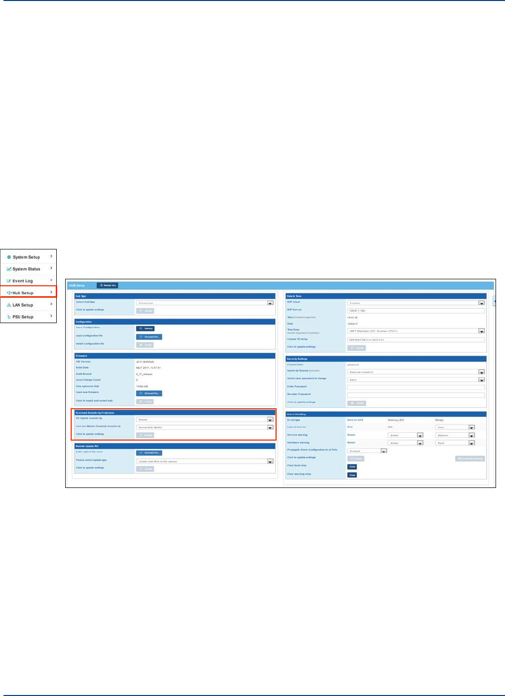
15.4
Remote Unit Settings
Remote Unit Settings
Understanding Hub Setup
You can set the Remote Unit overload sensitivity and update Remote Units
15.4.1. RU Uplink Sensitivity
You can protect the Remote Unit from very high signal levels. The AGC/Overload monitoring is done in
the Remote Unit using thresholds supplied by the Hub.
The reaction of the overload is in real time and immediate. The AGC kicks in as soon as the power
level detected reaches the threshold set. There is no set period that must expire before the AGC is
cleared. It is cleared as soon as the power level drops. Since the Remote Unit constantly monitors, as
soon as the power level drops below the threshold (minus the 0.5db margin), the system becomes fully
operational. There is a 0.5 dB hysteresis built into the software on the power level monitoring to stop
the AGC/Overload from oscillating.
To set Remote Unit signal sensitivity:
1.
Click Hub Setup in the left navigation bar.
Installation and Configuration 15-5
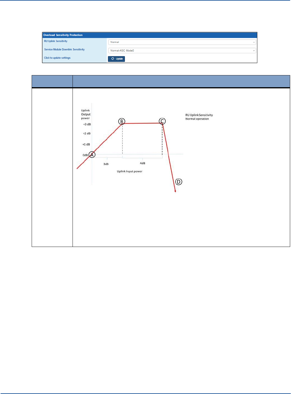
Remote Unit Settings
Understanding Hub Setup
2.
Select the desired sensitivity from the RU Uplink Sensitivity pulldown in the Overload Sensitivity
protection pane.
Type
Description
Normal
Provides overload protection in accordance with regulatory standards for spurious
emissions. For example,
Point A is the value set in system setup for “Uplink Power”. The default value for
this is -25dBm. In this case, if the composite RF input signal increases by up to 3
dB (Point B) above, the set Uplink power value the remote will continue to operate
normally and the output will increase linearly by 3 dB. If the signal level increases
further the Remote unit will apply AGC and limit the signal level (Points B to C). If
the signal level increases to more than 7 dB over Point A the remote unit will shut
the input power off completely.
15-6 Installation and Configuration
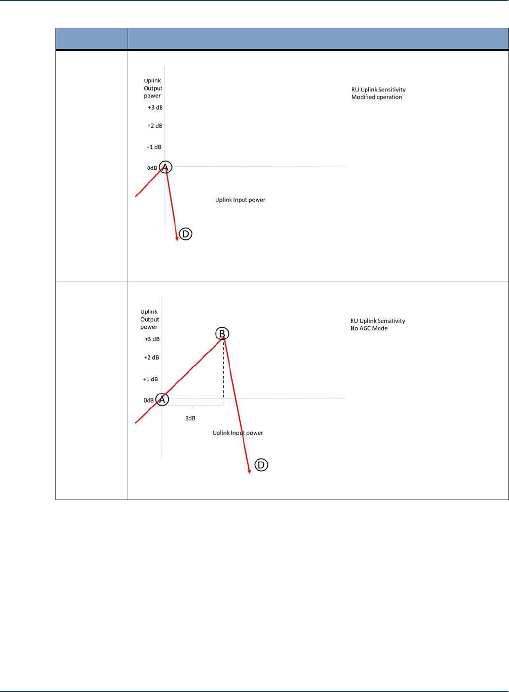
Remote Unit Settings
Understanding Hub Setup
Type
Description
Modified
More sensitive protection. For example,
In modified mode the Remote Unit shut off occurs at the specified input level. This
is the most sensitive setting and is used for specific service types.
No AGC
No overload protection.For example,
In No AGC mode the Remote Unit shut off occurs after a 3 dB linear increase.
3.
Click Update.
Installation and Configuration 15-7
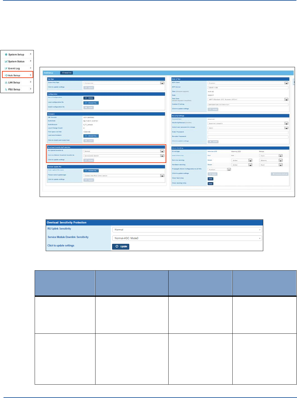
Service Module Downlink Sensitivity
Understanding Hub Setup
15.5 Service Module Downlink Sensitivity
You can protect the Service Module from very high signal levels. This is only applicable to Primary
Hubs.
To set Service Module signal sensitivity:
1.
Click Hub Setup in the left navigation bar.
2.
Select the desired sensitivity from the Service Module Downlink Sensitivity pulldown in the
Overload Sensitivity protection pane.
There are six settings:
Type
Description
Linear Increase
(above Calculated
level)
AGC Range (output
limited to max linear
increase
Normal-AGC Mode0
Provides overload
protection in accordance
with regulatory standards
for spurious emissions.
Default.
0-3 dB
3-7 dB
AGC Mode1
Provides a maximum
overload of 7dB
compared to the
Calculated Input Level.
Only use when
recommended by
Zinwave.
0-4 dB
4-7 dB
15-8 Installation and Configuration
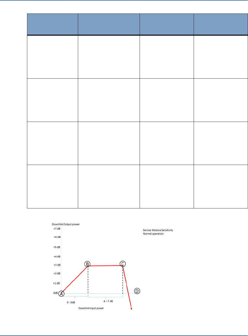
Service Module Downlink Sensitivity
Understanding Hub Setup
Type
Description
Linear Increase
(above Calculated
level)
AGC Range (output
limited to max linear
increase
AGC Mode2
Provides a maximum
overload of 7dB
compared to the
Calculated Input Level.
Only use when
recommended by
Zinwave
0-5 dB
5-7 dB
AGC Mode3
Provides a maximum
overload of 7dB
compared to the
Calculated Input Level.
Only use when
recommended by
Zinwave.
0-6 dB
6-7 dB
AGC Mode4
Provides a maximum
overload of 7dB
compared to the
Calculated Input Level.
Only use when
recommended by
Zinwave.
0-7 dB
NA
No AGC (0)
No AGC range and cuts
off if the input signal
exceeds the specified
level by more than 3dB.
Only use when
recommended by
Zinwave.
0-3 dB
NA
Under normal operation Point A is the value set in System Setup for Calculated Input Level dBm.
“Calculated Input Level” on page 14-12.
Installation and Configuration 15-9
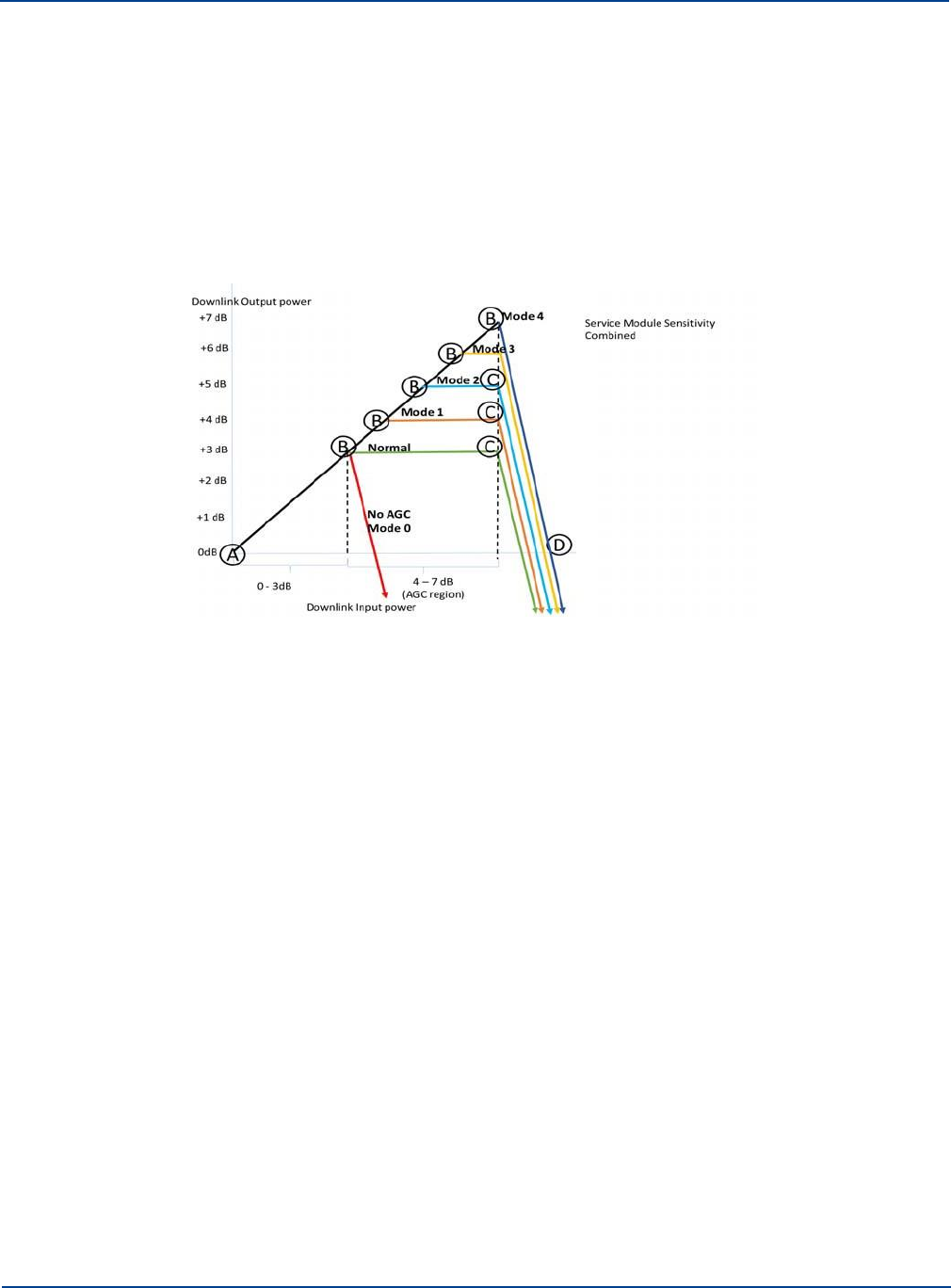
Service Module Downlink Sensitivity
Understanding Hub Setup
In this case if the composite RF input signal increases by up to 3 dB (Point B) above the specified
Calculated Input Level value the Service Module will continue to operate normally and the output
will increase linearly by 3 dB.
If the signal level increases further the Remote unit will apply AGC and limit the signal level (Points
B to C). If the signal level increases to more than 7 dB over Point A the module will shut the input
power off completely.
In order to provide flexibility and to account for possible gain variations the 5 alternate settings
have been provided. Modes 1-4 provide different ranges for linear increase compared to
AGC.Mode 0 provides no AGC range and cuts off if the input signal exceeds the specified level by
more than 3dB
These should only be used under advice from Zinwave.
3.
Click Update.
15-10 Installation and Configuration

Chapter 16: Understanding Alarms and
Reporting
16.1
Alarms
The term Event is a generic term for any occurrence in the system that could cause an entry in the event
log to be generated. Events are defined into four categories.
•
Loss of Service
•
Service warning
•
Hardware Warning
•
Informational
Some events also cause alarms, and are sub-divided as described in the following sections. All of these
event types are recorded in the log files accessible in the Configuration GUI. See “Event Log” on page
17-3.
16.1.1. Loss of service
This type of event occurs when the Primary Hub detects an event that will result in the complete loss of
1 or more services in at least 1 RU location, e.g. a link calibration failure, Overload “Safe Mode”, RU
communication timeout, thermal shutdown, etc.
A typical example of a loss of service alarm occurs when a Remote Unit is disconnected from the
system.
The log file will show the following type of behavior (Note log files are in chronological order)
2014-08-15 19:23:31: Cleared loss of service alarm: "Device is missing" on RU S/N:
310220000081 RU System
2014-08-15 19:23:31: RU02 (0x01D90611) detected connected to Optical Module 2
2014-08-15 19:23:31: RU02 (0x01D90611) has been deleted
2014-08-15 19:23:31: Raised loss of service alarm: "Device is missing" on RU S/N:
310220000081 RU System
16-1

Alarms
Understanding Alarms and Reporting
16.1.1.1.
Loss of Service Alarms
Alarm
Description
Action
Calibration error
An error has occurred in the
calibration of an optical link.
Either carry out a manual
recalibration through the status page
for the relevant module or remove the
optical cable which will force a
recalibration to occur. If the fault
persists check the equipment at both
ends of the affected link.
RU services are
The system cannot be
Check that each Matrix has valid
restricted by a missing
configured as desired and
input and output paths set
Service Module, or by
some services will not be
matrix settings
present due to incomplete
Matrix settings.
The uplink power has
exceeded the safe limit,
and the receiver has
been turned off
The power in the uplink
(primarily the Remote Unit) has
exceeded the defined
threshold. This will cause the
LNA in the Remote Unit to
switch off until the overload
condition is removed.
Remove the overload condition
It can be caused by
uncontrolled uplink power from
Mobiles or by poor installation
causing reduction in Tx Rx
isolation.
The downlink power has
This relates primarily to the
Check the measured input level and
exceeded the safe limit,
service Module and is raised
either modify input settings value or
and the receiver has
when the downlink power from
reduce BTS input level to the level
been turned off
the connected BTS or Repeater
required.
exceeds the specified input
level.
Device is missing
A unit that was present at the
application of Auto setup is no
longer connected to the system.
Correct or accept
16.1.2. Service Warning
This type of event is one that may be affecting the performance of at least 1 service in at least 1 RU
location, e.g. a bad optical link, Overload “AGC Mode”, etc.
E2014-07-03 14:51:07: Raised service warning alarm: "Uplink has poor RF performance"
on PH Optical Module 1
16-2 Installation and Configuration

Alarms
Understanding Alarms and Reporting
16.1.2.1. Service Warning Alarms
Alarm
Description
Action
Configuration has not
been confirmed by the
user
The settings of the system need
to be confirmed by running auto
setup.
Validate Setup.
The requested
composite power could
not be achieved
The output power requested at
set up for a Remote Unit cannot
be achieved. This will be due to
a poor optical link which
requires too much
compensation (gain).
Check Optical connections and link
quality.
Uplink Automatic Gain
Control activated
This indicates that the Remote
Unit has detected a signal
above its defined threshold. It is
currently working in the “safe”
region before it switches off
completely.
This indicates that the remote unit is
sensing a higher than expected uplink
RF level. This may be due to the
temporary presence of a high power
mobile without power control close to
the antenna or a lack of isolation
between transmit and receive
antenna ports.
If the condition is transitory then
consider setting the Uplink sensitivity
to a higher level. If the alarm is due to
poor isolation between antennas
either space antennas correctly or
adjust uplink sensitivity setting for this
remote unit.
Downlink Automatic
Gain Control activated
This indicates that the Service
Module has detected a signal
above its defined threshold. It is
currently working in the “safe”
region before it switches off
completely.
This indicates that the service module
is sensing a higher than expected
uplink RF level from the connected
RF source. This may be due to an
incorrect setting for input power or an
unexpected increase in BTS output.
Check the measured input signal to
the Service module and against
expected input signal loading and
levels, paying special attention to
level changes caused by pilot back
off.
If the level has increased due to
unexpected increase in either
channel numbers or service types,
check with BTS providers and modify
setting accordingly.
Uplink has poor RF
performance
The uplink optical link has poor
performance usually due to
high optical loss.
Check and clean link.
Installation and Configuration 16-3

Alarms
Understanding Alarms and Reporting
Alarm
Description
Action
Downlink has poor RF
performance
The downlink optical link has
poor performance usually due
to high optical loss.
Check and clean link.
Uplink gain is limited by
The uplink gain is limited by the
The system will automatically try and
the maximum allowable
maximum input signal level at
set the uplink gain to be the same as
output power of a
the Remote Unit and the
the downlink gain. If the uplink
Service Module
maximum output level of the
sensitivity is set too high this will limit
Service module (-10 dBm).
the uplink gain and will raise this
condition.
UL gain setting too high,
decrease balance
The uplink gain is potentially
greater than the downlink gain.
The system will automatically set the
Uplink gain to be the same as the
downlink gain with a UL/DL balance
of 0, but will show this condition
indicating that the UL /DL balance
can be adjusted if required.
If the value provided at System setup
requires greater than this the input
value will be adjusted while
maintaining the requested output
power The delivered input power
should be adjusted (raised) to ensure
that excessive gain is not required.
“Required uplink gain is
too high.”
Input level too low -
changing to appropriate
level
The system cannot achieve the
required output with the input
level set on the Set Up page.
“The SM Calculated
Input Level has been
changed to prevent the
downlink gain from
being too high.”
The system has a maximum
gain of 25 dB between service
level input and Remote Unit
output power settings.
Different power levels
on uplink matrix input
The system has detected that
there are inconsistencies with
the automatic setting of the
internal system parameters due
to in equalities in connected
components.
This should not prevent satisfactory
operation but all set values for all
elements connected to the affected
Matrix should be checked (RU output
etc power and all l optical links should
be checked to ensure that they are
performing inside optical limits.
16.1.3. Hardware Warning
This type of event is one that may be affecting the performance or lifespan of a component, e.g.
temperature, voltage or current limits, fan failure, etc.
2014-08-15 19:24:11: Raised hardware warning alarm: "The uplink power is above the
upper limit" on PH Optical Module 2
In each case of a hardware warning the unit identity is included in the message.
This condition can also be cleared if you disable the faulty component through the System Setup
window, or Apply a new set of parameters that disable the potentially affected service(s) at the affected
location(s). For Hardware warnings this condition is also self-cleared by the Hub if the component
returns within limits.
16-4 Installation and Configuration

Alarms
Understanding Alarms and Reporting
16.1.3.1. Hardware Warning Alarms
Alarm
Description
Action
The module
temperature is above
the limit
The module
temperature is below
the limit
In each case the unit affected
will be included in the log
message Example “The module
temperature is above the upper
limit” on PH PSU.
The cause will be the ambient
temperature of the device in
question.
Adjust the temperature or trace the
specific problem through the
equipment. See specif over and
under temp alarms below.
Current1 over limit
This indicates a problem with
the power supply rails of the
device in question. In the case
of Optical Modules, Service
modules and Hub alarms it
relates to the Hub Power
supply. If the alarm is raised in
conjunction with a Remote Unit
the fault will be with local unit or
the centralized feed.
Contact Support and arrange for unit
RMA in accordance with you
maintenance and support agreement.
Current1 under limit
Current2 over limit
Current2 under limit
Voltage1 over limit
Voltage1 under limit
Voltage2 over limit
Voltage2 under limit
3.3 volt supply fault
These are Hub alarms
indicating problems with the
Hub power supply. Some are
used directly by modules and
others are intermediate step
down voltages.
+ve 5 volt supply fault
15 volt supply fault
-ve 5 volt supply fault
Optical communications
fault
PSU 13v supply fault
PSU 3.3v supply fault
PSU 8v supply fault
PSU -ve 12v supply
fault
PSU comms error
PSU 13v supply current
over limit
Power supply fault
Fan fault
The fan speed is monitored as
part of the internal control of the
Hub. A fan fault will either
indicate a power supply issue or
functional problem with the fan.
Check for build-up of dirt and dust
and replace as required.
Installation and Configuration 16-5

Alarms
Understanding Alarms and Reporting
Alarm
Description
Action
The uplink power is
below the lower limit
The received optical power is
below the minimum threshold
for satisfactory operation and
will result in any connected
modules being disconnected/
deleted. The problem can be
either a power failure at the far
end or a break in the optical
fiber cable.
Check the optical connection and
fibers for damage, cleanliness and
poor connection. If necessary clean
both side of the optical interface
carefully and replace if damaged.
The uplink power is
above the upper limit
The optical power level exceeds
the maximum value in the case
of an optical link or if reported in
conjunction with a Remote Unit
identity indicates that the
overload value for the Remote
has been exceeded.
In the case of the service module this
will be due to higher than expected
RF signal levels from the connected
RF sources. Measure input signal
and check against the set value.
Correct settings or report increase in
BTS signal to operator.
The downlink power is
below the limit
The received optical power is
below the minimum threshold
for satisfactory operation and
will result in any connected
modules being disconnected/
deleted. The problem can be
either a power failure at the far
end or a break in the optical
fiber cable.
Check the optical connection and
fibers for damage, cleanliness and
poor connection. If necessary clean
both side of the optical interface
carefully and replace if damaged.
The downlink power is
above the limit
The optical power level exceeds
the maximum value in the case
of an optical link or if reported in
conjunction with a Service
Module indicates that the stated
input level has been exceeded.
In the case of the service module this
will be due to higher than expected
RF signal levels from the connected
RF sources. Measure input signal
and check against the set value.
Correct settings or report increase in
BTS signal to operator.
System error
This indicates a low level
system error in the reporting
unit.
These are non critical errors and
alarms that may occur as part of
normal operation. They are not critical
and can be masked if required.
16.1.4. Informational
This category covers information presented to the user in the log file which records events that have
been carried out by the user such as application of a new system set up, changing time and date or
passwords. These are for information only and will not raise an alarm.
2014-06-13 14:33:22: New System Setup being set by: advanced.
16-6 Installation and Configuration
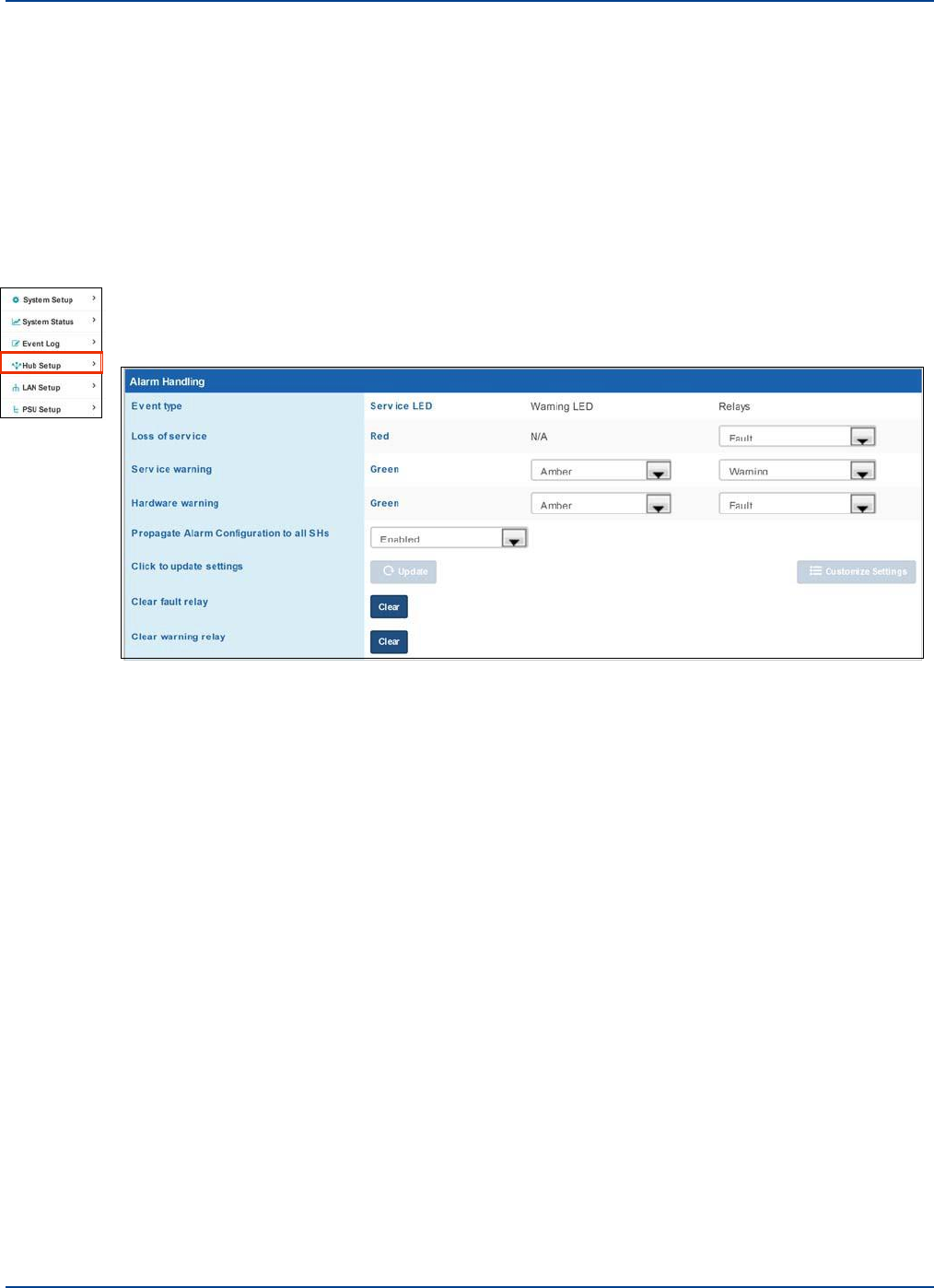
16.2 Alarm Handling
16.2.1. Clearing Relays
Alarm Handling
Understanding Alarms and Reporting
You can clear fault or warning relays. This requires Advanced user privileges. When connected to a
Primary Hub, all Secondary Hub relays are also cleared. When Connected to a Secondary Hub, only
the relays on the Hub connected are cleared.
To clear Fault or Warning Relays:
1.
Click Hub Setup in the left navigation bar.
2.
In the Alarm Handling pane, click the Clear button next to Clear fault relay or Clear warning relay.
16.2.2. Alarm Handling Configuration
You can change how the Hub is configured to react for the three Event types (loss of service, service
warning, and hardware warning). Where applicable, you can change the Warning LED and Fault relay
via the software.
You only need to setup alarms for the system via the Primary Hub. If enabled, the settings filter down
to all connected Secondary Hubs. Propagation is by default set to Enabled. If one or more Secondary
Hubs needs a different configuration, it is advised to set all to the same and then manually connect to
individual Secondary Hubs
Installation and Configuration 16-7
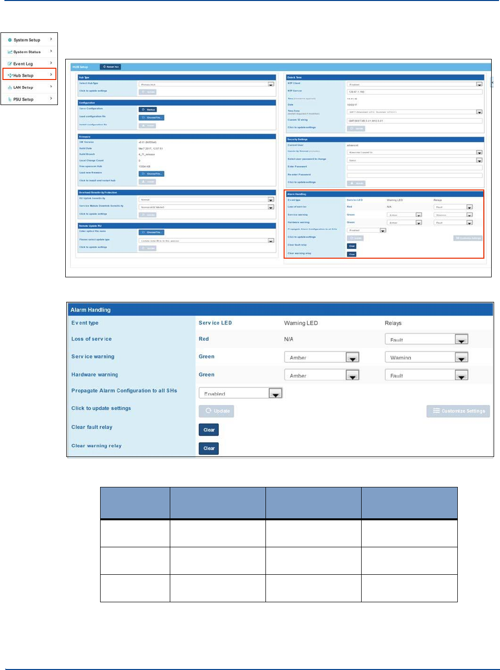
Alarm Handling
Understanding Alarms and Reporting
To change alarm handling settings:
1.
Click Hub Setup in the left navigation bar.
2.
In the Alarm Handling pane, select the desired settings from the pulldown where available.
Event Type
Service LED
(not editable)
Warning LED
Relays
Red
Red
N/A
Fault, Warning, or
Ignore, Custom
Green
Green
Green or Amber
Fault, Warning, or
Ignore, Custom
Green
Green
Green or Amber
Fault, Warning, or
Ignore, Custom
16-8 Installation and Configuration
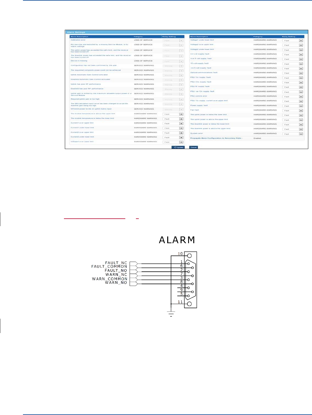
Alarm Connections
Understanding Alarms and Reporting
If Custom is selected, the Customize Settings button is activated. Click this button to enter the
desired custom settings.
Depending on relay selected, options may be grayed out or available.
Select the desired options from the pulldowns and click Update.
3.
Click Update.
16.3 Alarm Connections
UNItivity 5000 can connect to external alarm sources or monitors via the 9-way D-type connector on
the Primary and Secondary Hubs. The connector provides 4 relay outputs: normally open alarm;
normally closed alarm; normally open warning; normally closed warning.
The relays are activated by an alarm or warning event. The relays are deactivated by clearing the
alarm or warning condition and resetting the alarm/warning filter.
Installation and Configuration 16-9
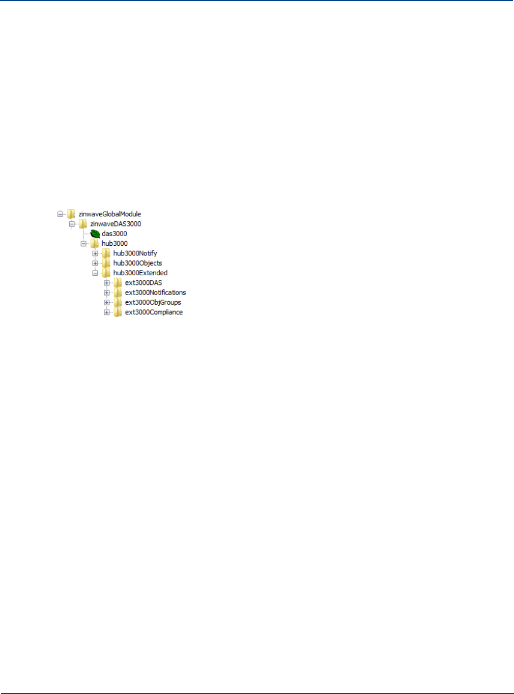
SNMP
Understanding Alarms and Reporting
16.4 SNMP
An SNMP interface supports integration with higher order NMS applications. Security features such as
separate user classes and secure communications via SSH & SSL are provided, along with support for
secure SNMP v3. Local diagnostics are also available via LEDs indicating equipment status on the
Hubs for rapid fault isolation.
The Hub firmware supports an SNMP v2 MIB interface, to remotely monitor the system by connecting
SNMP Master Devices, such as Network Operation Center software, to Hubs. Both Hub types support
the SNMP interface, but it is recommended that only the Primary Hub’s interface is monitored,
otherwise an alarm originating on a Secondary Hub can be reported by both.
SNMP Get and SNMP Traps are currently supported, the following tree view shows the structure of the
interface:
16.4.1. Snmp Trap Events
The Fault Relay Status trap will be sent for all alarms which are reported by the Primary Hub. The Fault
Relay activates and the SNMP fault relay status trap is sent, in the event of an alarm. When the first
trap is sent, the fault relay is set, subsequent traps are sent for additional alarms raised even if the fault
relay has not been cleared. This feature is not enabled during the first 5 minutes from power on of the
system. This initial start-up phase is to allow for any transient start-up alarms which may occur prior to
the system coming online.
It should be noted that neither relay is self-cleared when the triggering alarm is cleared. Relays must
be cleared manually via the GUI.
16.4.2. SNMP Get Objects
The following objects can be queried using v2 SNMP Get requests:
•
Hub3000Objects.Hub3000String – This is the label of the Hub, as has been set in System
Setup.
•
Hub3000Objects.Hub3000DeviceType – This is the type of UNItivity 5000 unit.
•
Hub3000Objects.Hub3000ModelName – This is the model name of the UNItivity 5000 unit.
•
Hub3000Objects.Hub3000FaultRelayState – The state of the fault relay, either set(1) or
cleared(0).
•
Hub3000Objects. Hub3000FaultDescription – A description of the last fault detected by the
system.
•
Hub3000Objects. Hub3000PrevFaultDescription – A description of the previous fault detected
by the system.
16-10 Installation and Configuration
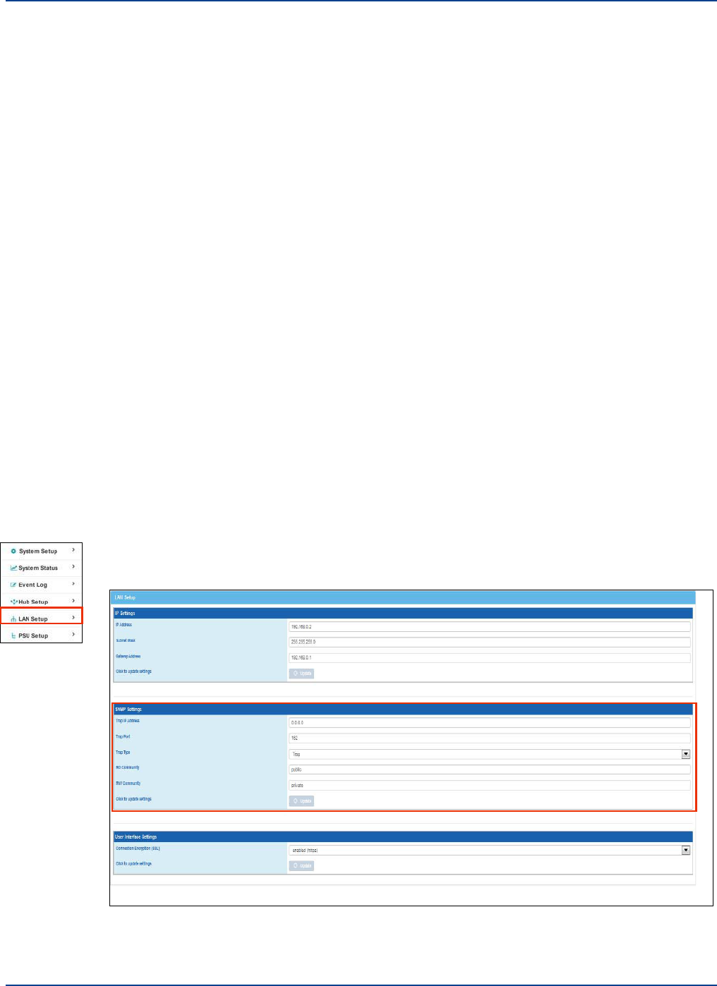
16.4.3. SNMP Traps
SNMP
Understanding Alarms and Reporting
The following SNMP traps are supported:
•
Hub3000Notify.Hub3000Heartbeat – This is a heartbeat trap which is sent every 20 minutes to
the listening SNMP manager. It contains the following objects: Hub3000String,
Hub3000DeviceType, Hub3000ModelName, Hub3000FaultRelayState
•
Hub3000Notify.Hub3000FaultRelayStatus – This trap is sent each time a new alarm is raised
in the system, and when the fault relay is manually cleared from the PH GUI. It contains the
following objects: Hub3000String, Hub3000DeviceType, Hub3000ModelName,
Hub3000FaultDescription, Hub3000FaultRelayState
The IP address and port of the SNMP trap receiver (SNMP Manager), is set via the LAN Setup page of
the Hub graphical user interface.
Some notes on the SNMP interface and alarms:
•
During start-up alarms will be written to the event log, but the fault relay will not set, and no
trap will be sent. This start-up period lasts 5 minutes.
•
If any alarms remain or any units are still missing once we complete start up, then the Hub will
loop through the alarm conditions and send out traps.
•
Uplink power under limit alarm is initially set, but then almost immediately cleared when the
unit connected to the fiber is deleted from the system. This causes a discrepancy that
customers have seen in the dump tables where the dump table is apparently clear, but they
have received a trap.
16.4.4. SNMP Settings
To set SNMP items:
1.
Click LAN Setup in the left navigation bar.
Installation and Configuration 16-11

SNMP
Understanding Alarms and Reporting
2.
Enter the Trap IP Address (IPv4) and Trap port number in the SNMP Setting pane.
The trap IP address is the address to send traps. 0.0.0.0 disables traps. The default trap port is
162.
3.
Select the Trap Type (Trap or Inform) from type from the pulldown.
4.
Enter the RO and RW Community strings if the default is not desired.
The SNMP Read-Only Community String is like a password. It is sent along with each SNMP Get-
Request and allows (or denies) access to device. The default password is “public”. Many network
administrators change the community string to keep intruders from getting information about the
network setup. This is a good idea. Even if it's only read-access, an intruder can learn a lot about a
network that could be used to compromise it.
There is also a Read-Write community string. that should never be set to “public”. The default is
private.
5.
Click Update.
16-12 Installation and Configuration
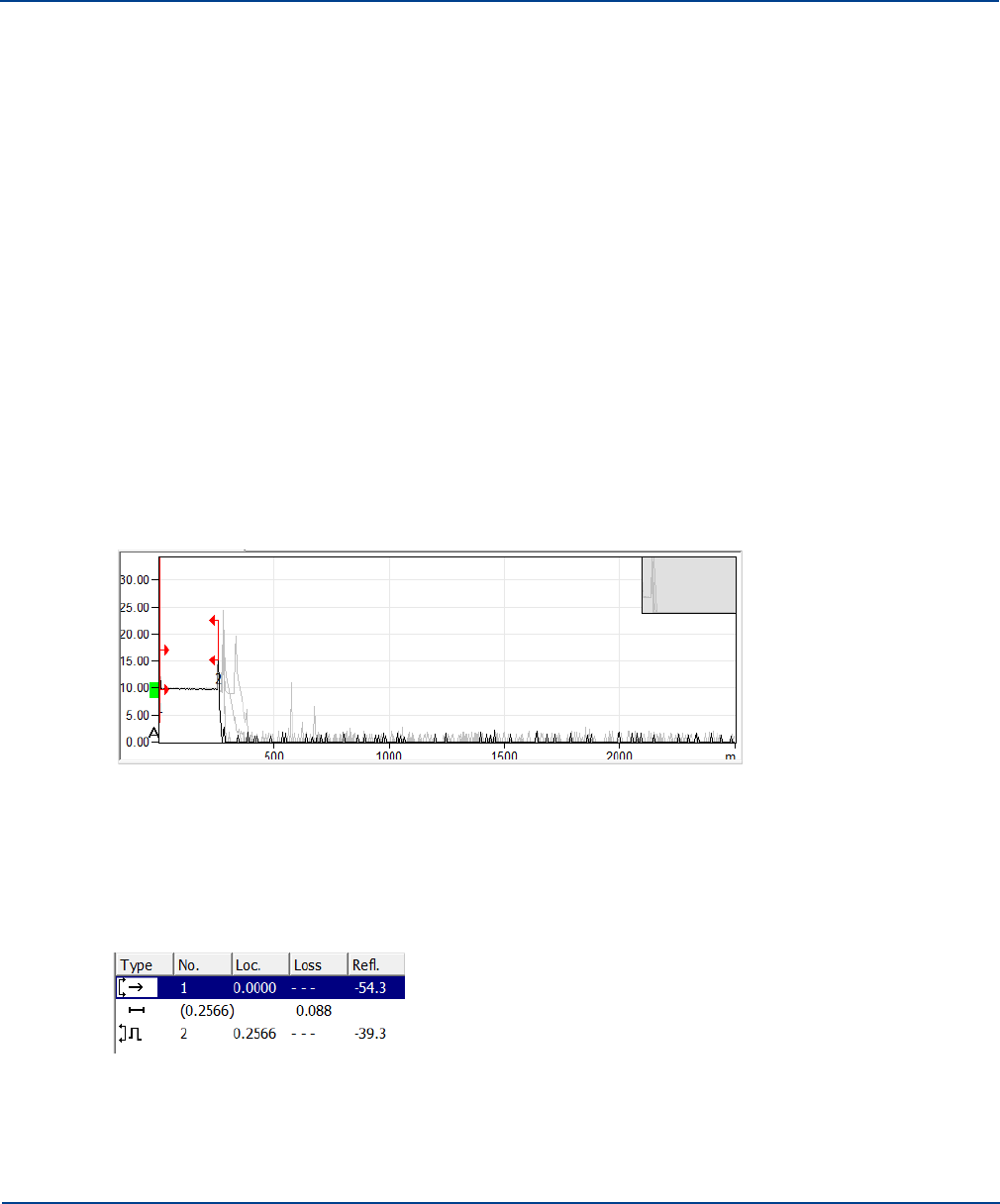
Chapter 17: Performing Diagnostics and Testing
17.1
Diagnosing Optical Links with an OTDR
The Infrastructure Cable between Hub Optical Module and Remote Unit must meet the following
specifications:
•
Maximum Optical Loss 5dBo
•
Minimum Optical Return Loss 30dB
This can be guaranteed with Singlemode fiber and APC connections throughout the installation.
17.1.1. Diagnose an Optical Link
In presence of high levels of back reflection due to poor Return loss, the Zinwave system performance is
degraded. The effects of this can be easily seen on the system and diagnosed using appropriate test
equipment. The effects of back reflection can be seen by looking at the level of the noise floor. In cases
where there are high levels of back reflection, the noise floor in either the downlink or the uplink can vary
significantly (10-15dB). It may also show as increased levels of harmonics which will also vary in level by
significant amounts.
The best way to check the return loss of a fiber link is to use an Optical Time Domain Reflectometer
(OTDR) with the appropriate connectors and launch cables. A typical graph result is shown below:
The graph shows the performance of fiber along its length. In this case the first horizontal line represents
the first 250m of fiber in the launch box. Each of the subsequent peaks relates to the situations where
internal reflection has occurred along the fiber length. This could be connectors, splices or even
damaged cables. Generally the highest peak shows the worst case of back reflection and hence source
of return loss and potential interference, depending on the OTDR used results, can be displayed in a
tabular form giving distances and the relevant reflection or return loss.
17-1
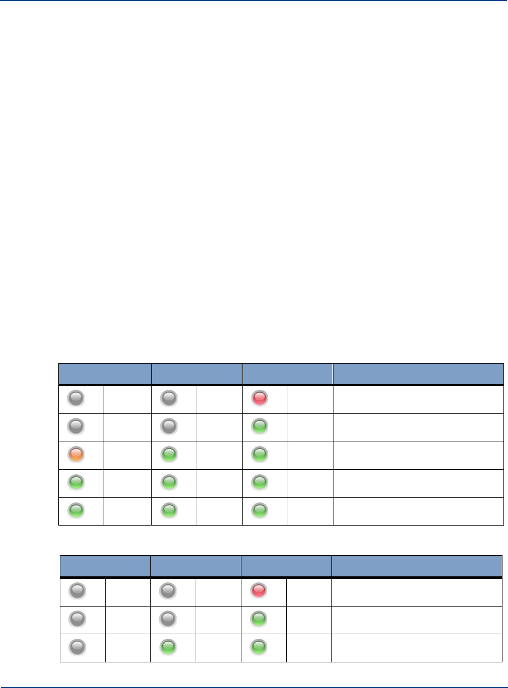
LED Testing
Performing Diagnostics and Testing
In the example above a single reflection of -39.3dB is present. In this case the -39.3dB reflection is at
the PC/PC interface at the end of the link and in a link with multiple connections there will be an event
for each connection.
It should be noted that the OTDR is not able to distinguish between 2 reflections very close to each
other over long lengths of cable and in the case of two reflections close together, only the worst
reflection will be shown. However this will allow installers to identify where in the overall fiber link the
problem occurs.Available in Left- navigation bar
17.2
LED Testing
17.2.1. Modules
In order to test the proper operation of the module LED’s, follow the steps below:-
1.
Insert an Optical Module into the front of a Primary Hub.
2.
Insert a Service Module into the rear of a Primary Hub.
3.
Connect the Optical Module to an Remote Unit.
The system should be set up with auto-Setup running and all alarms enabled as faults. The
following test sequence should be followed:
4.
Switch off the Hub at the mains switch
All module LED’s will be off
5.
Switch on the Hub at the mains switch
The Optical Module LED’s will follow the sequence shown below:
Left
Middle
Right
Status
Off
Off
Dull
Red
Initial start-up. Basic Power present
to allow Module detection
Off
Off
Green
Module detected and full power
connected to module
Orange
Green
Green
Optical link in calibration
Green
Flash
Green
Green
Calibration complete, but final
output stage not enabled
Green
Green
Green
Fully operational
The Service Module LEDs will follow the sequence shown below:
Left
Middle
Right
Status
Off
Off
Dull
Red
Initial start-up. Basic Power present
to allow Module detection
Off
Off
Green
Module detected and full power
connected to module
Off
Green
Green
Module Fully Operational
17-2 Installation and Configuration
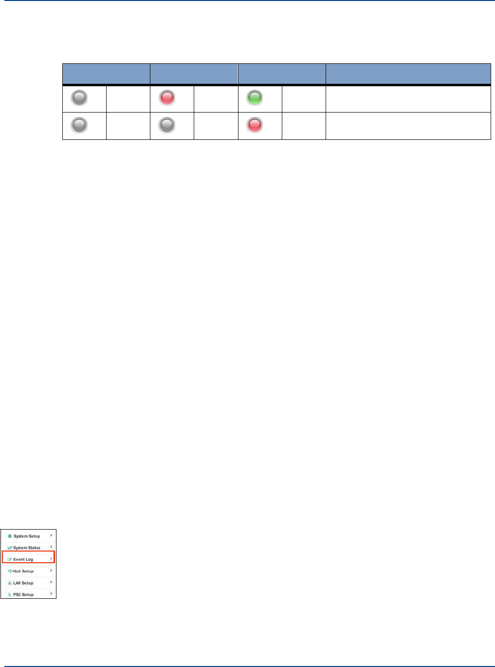
Event Log
Performing Diagnostics and Testing
6.
Disconnect the optical fiber from the Optical Module connector. The Optical Module LED’s will
alternate between the states shown below:
Left
Middle
Right
Status
Off
Red
Green
Communication failed with Remote
Unit
Off
Off
Dull
Red
Basic Power present to allow
Module detection
7.
Wait at least 10 seconds then reconnect the optical fiber to the Optical Module. The Optical
Module LED’s will follow the same sequence shown in step 2 above.
Note: It is not possible to initiate a module alarm so the left side LED “RED” state cannot be tested.
17.2.2. Remote Unit LED Test
In order to test the correct operation of the Remote Unit LED, connect the Remote Unit to an Optical
Module in the front of a Primary Hub. The power supply should not be connected.
The following test sequence should be followed:
1.
Power up the Remote Unit by plugging in the power supply
The LED will follow the sequence:
OFF – RED – ALT. RED/GREEN – GREEN FLASH – ORANGE – GREEN
2.
Using “Hub Setup” disable the Remote Unit output
The LED will FLASH Hub GREEN
3.
Using “Hub Setup” re-enable the Remote Unit output
4.
The LED will go GREEN
Note: It is not possible to initiate a Remote Unit alarm, so the RED Secondary Hub state cannot be
tested.
17.3 Event Log
Each activity that takes place on this system is recorded as an event. Events can be informational or
can generate alarms. For detailed information about alarms See “Understanding Alarms and
Reporting” on page 16-1. The last 200 events are saved and recorded in the on-screen event log.
17.3.1. Viewing and saving the Event Log
To view the Event Log:
1.
Click Event Log in the left-navigation bar.
Installation and Configuration 17-3
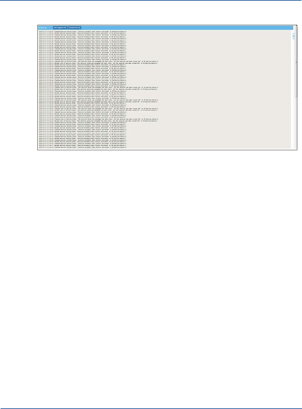
Event Log
Performing Diagnostics and Testing
The Event Log is shown.
The Event log is also accessible via System Tools. See “View Event Log” on page 13-9.
2.
Scroll through the log to see it’s details.
3.
Click Download the Event Log to save the current state of the of the log to a specified location.
Note: Depending on your browser, the file may automatically download to a predetermined location. If
this is the case, navigate to the file and move or copy the file as desired.
The file is saved as text files and can be opened in any text editor.
17.3.2. Logging Events to a USB
You can log events to a USB drive. This allows you to record a maximum of 4GB worth of event data.
If the event log extends beyond 4GB, logging is disabled. Data sent to the USB is divided into a Raw
log and an Event log. The Raw log provides all detailed logging including internal diagnostics and this
data may be required for diagnosis. You must setup the file structure on the USB in order for the device
to log properly.
To setup the file structure on a USB:
1.
On a computer, insert an empty USB with 4GB of storage, into a USB drive.
Note: You cannot configure the USB through the Hub.
2.
Add the following folder on the USB drive: log_event
Ensure the spelling and capitalization is the same as listed and the underscore appears as listed.
3.
Insert the formatted USB into the desired Primary or Secondary Hub.
To log events to a USB dive:
1.
Click Event Log in the left-navigation bar.
The event log is shown.
2.
Insert a formatted USB into the desired Primary or Secondary Hub’s USB port.
17-4 Installation and Configuration
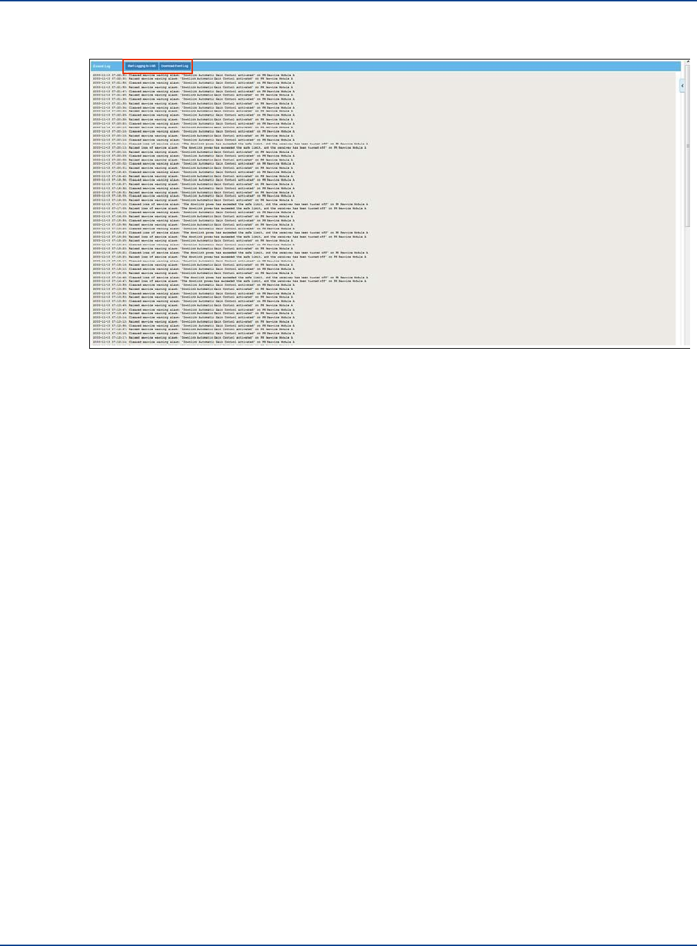
Interpreting System Layout Tables
Performing Diagnostics and Testing
3.
Click Start Logging to USB.
4.
When finished logging, click on the Stop Logging To USB Event Log screen.
Important: If the USB drive is removed without stopping the logging process, the logging feature will
be disabled and can only be re enabled with a Hub reset.
If the correct file structure is not in place on the USB drive the following is displayed in the onscreen
Event log when logging is requested.
2013-11-28 14:55:28: Stop Storing logs.
2013-11-28 14:55:21: There is no log_event folder on USB.
2013-11-28 14:55:21: There is no log_raw folder on USB.
2013-11-28 14:55:21: Start Storing logs.
All log files are .txt files and each file is recorded with the start time and date in the file name. They can
be viewed in any text editor.
17.4 Interpreting System Layout Tables
You can view and save a detailed description of the current System layout. This can assist you in
isolating system configuration or signal processing issues. Viewing the system layout from a Primary
Hub, downloads all information for all configured Secondary Hubs and Remote Units associated with
that Primary Hub. Downloading from Secondary Hub, does not show the Primary configuration.
In order to interpret the System Layout files that you save you must:
1.
Convert the file to an Excel format.
2.
Interpret the Excel sheets.
Installation and Configuration 17-5
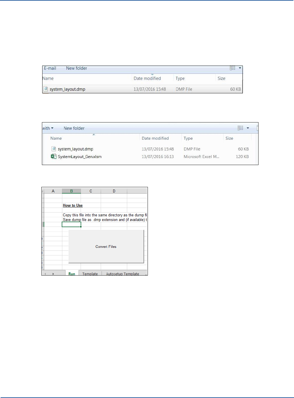
Interpreting System Layout Tables
Performing Diagnostics and Testing
17.4.1. Converting the System Layout File to Excel
To generate files viewable in the System Layout Tool:
1.
View and save the system layout file as described in “View System Layout” on page 13-8.
2.
Open the folder for the location to which the file was downloaded.
The filename will be system_layout.dmp.
3.
Save the file to your desired location.
4.
Copy the file SystemLayout_Gen.xlsm from the USB drive (or zinwave.com) to the same
location.
5.
Open the Excel file and make sure Macros are enabled.
6.
Click the Run tab.
7.
Click the Convert Files button.
The Save As window appears.
17-6 Installation and Configuration
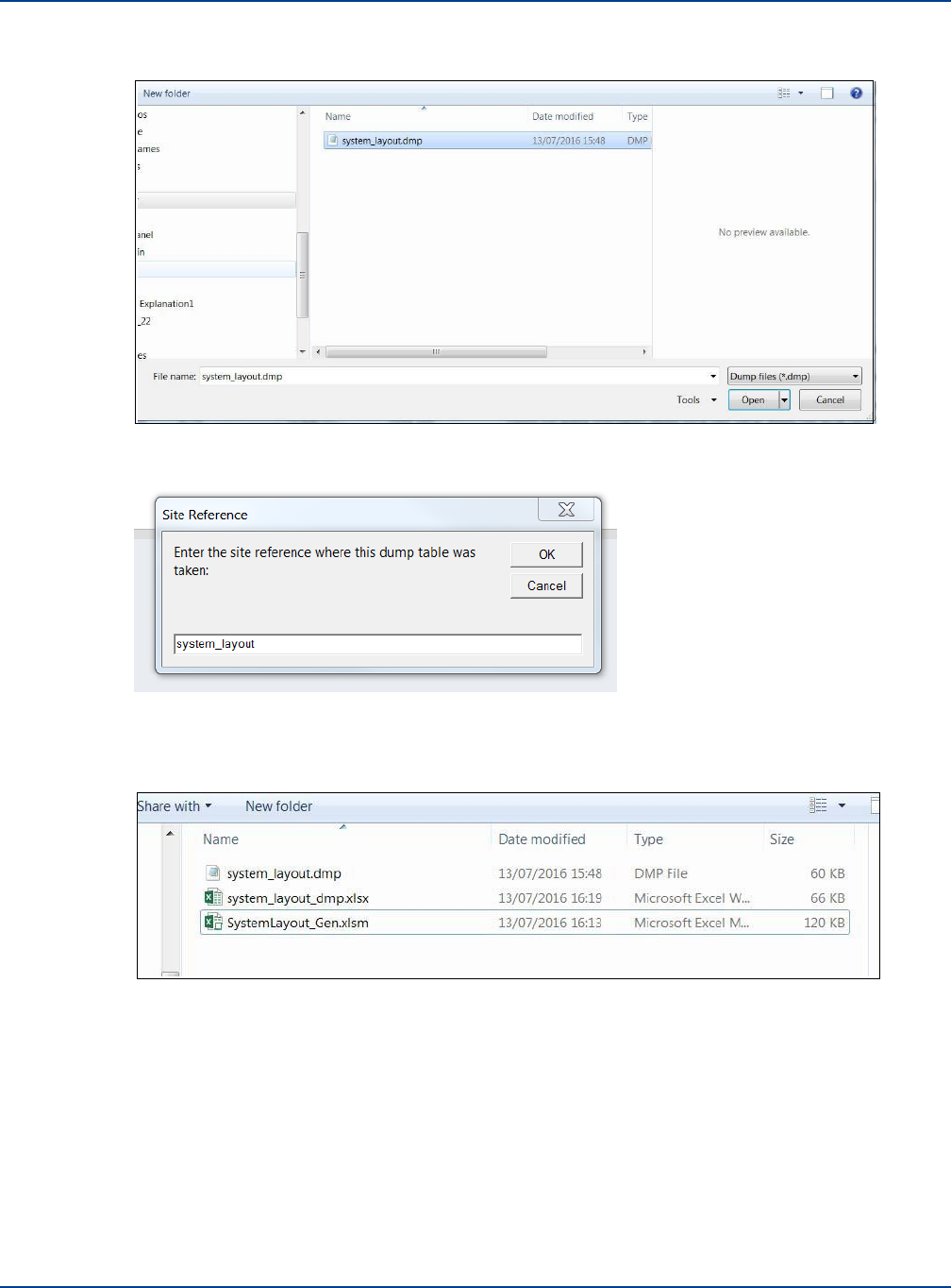
Interpreting System Layout Tables
Performing Diagnostics and Testing
8.
Select the .dmp file to be converted.
9.
Click Open.
A window appears asking for details for a site reference as shown here.
10.
Click OK.
11.
When the confirmation window appears, click Yes.
The file is launched in Excel and is saved as an Excel file in the same location. No closes the tool.
Installation and Configuration 17-7
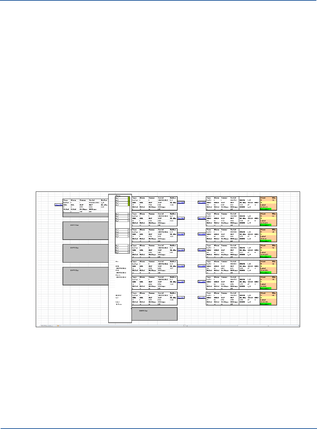
Interpreting System Layout Tables
Performing Diagnostics and Testing
17.4.2. Interpreting the Excel File
The System Layout Tool is an Excel file that has been especially created to help you view the mass
quantity of information initially gathered about the currently configured system. The system layout
sheet displays all of the data stored for each of the modules and link within the system.
The tool takes the data saved and converted in“Converting the System Layout File to Excel” on page
17-6 and displays it back to you in an organized format in an Excel Workbook consisting of 5 sheets:
•
System Layout
•
Autosetup
•
Link Quality
•
Misc
•
Tables
After you convert the file, the file is automatically opened. You can return the file at anytime by opening
the system_layout_dmp.xlsx file from where you saved it.
17.4.2.1.
System Layout Sheet
The system layout sheet displays all parameters of the connected system. This provides a summary of
all the data that can be accessed through each module via the System Status page.
17-8 Installation and Configuration
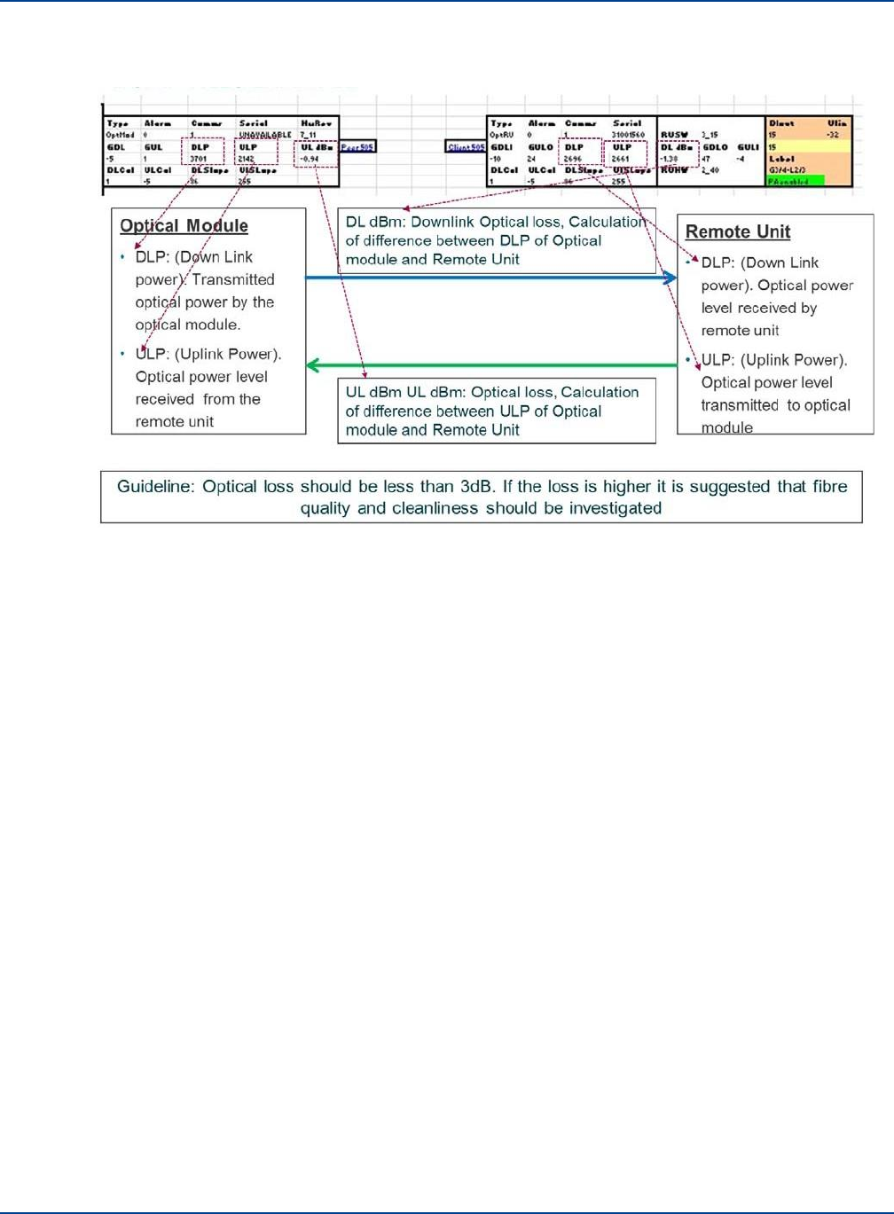
Interpreting System Layout Tables
Performing Diagnostics and Testing
You can look at the details listed on this sheet to gather details about the current configuration. The
following diagrams zooms in and describes the sheet.
17.4.2.2.
Autosetup Sheet
The Autosetup page provides a summary of the information input to set the system up along with
details of any warnings or set up errors that may be present in the setup process.
17.4.2.3.
Link Quality
The Link Quality tab provides a summary of the optical performance of all links within the system and
included individual up and downlink gain and calibration figures.
17.4.2.4.
Misc
The Misc tab provides details of the DC power input to each Remote Unit.
17.4.2.5.
Tables
The Table tab contains the raw data initially shown on the GUI screen. This data is interpreted and
used to display the other tabs.
Installation and Configuration 17-9

Interpreting System Layout Tables
Performing Diagnostics and Testing
17-10 Installation and Configuration

Chapter 18: Preventive Maintenance and
Cleaning
Ongoing maintenance of the system hardware can extend and enhance the life of the system.
Caution: Utilize proper system de-energize and tag-out procedures before completing any
maintenance. Incorrect de-energization and tag-out procedure can cause damage or personal injury.
18.1
General Equipment Cleaning and Inspection
Equipment maintenance should be performed in accordance with Manufacturer’s instructions. The
following are general guidelines for equipment maintenance.
•
Wipe component exteriors surfaces (plastic/metal) with a soft lint-free cleaning cloth moistened
with a solution of three parts water and one part dishwashing detergent.
Note: Do not soak the cloth or let water drip inside the component.
•
Fans, cable connections, cable routing, and other key components should be inspected for
degradation.
•
Inspect hardware for loose or trampled wires.
18.2
Hardware Maintenance Frequency Guidelines
The Status page of the GUI can be used to monitor the entire system, however regular maintenance
should be performed to ensure normal operation.
The following items should be checked:
•
General Cleanliness and connections for Rack Mounted equipment
•
Fiber Infrastructure and Fibers
•
Antenna Cables and Remote Unit Connections
Zinwave recommends the following maintenance guidelines. More frequent maintenance may be
needed if the environment is not cleaned and maintained.
Every 3
Months
Every 6
Months
Perform general cleaning and inspection
X
Check firmware and hardware updates
X
18-1

General Cleanliness and Rack Mounted Equipment
Preventive Maintenance and Cleaning
18.3
General Cleanliness and Rack Mounted Equipment
All rack mounted equipment (Hubs and power supplies) is designed to be installed in dust free and
temperature regulated environments.
Every 3 months
•
Check for dust ingress and build up and cleaned as appropriate using a soft lint free cloth.
•
Fans should be inspected for degradation and excessive noise.
•
Cable connections for both power and data should be inspected for degradation, including
excessive bending and pinching and damage.
18.4
Fiber Cleaning and Inspection
All fiber connections can be assessed using the Link Quality Tool or through the System Layout tool.
All values for loss should be compared to the original installed (handover) values. Any links showing
signs of degradation should be cleaned.
18.4.1. Inspection
The optical fiber connection has two basic performance indicators Insertion loss and Return loss. Poor
performance in either of these areas degrade the overall system performance. Physical inspection of
all fibers should include checking bend radius of fibers and patch cords as excessive bending will
impact both insertion loss and return loss (reflection).
18.4.1.1.
Insertion Loss
The optical loss can be seen for each link by looking at the status page of the web GUI and examining
each connection in turn or alternatively making a dump of the entire system data and examining it
through the layout tool.
This can be caused by a number of problems (most of which can be resolved simply):
•
Incorrectly mated connectors: An incorrectly mated connector will cause either a misalignment
of the optical fiber or an air gap between the two ferrule faces. In either case a high insertion
loss will be seen.
•
Dirty Connectors: dirt on the face of optical connectors will cause higher insertion loss, which
can be reduced by careful cleaning of the fibers.
•
Poor splice assembly. In some cases infrastructure will include splices. These can, if done
poorly, show up as high insertion loss. (They will also cause poor return loss). If the insertion
loss is due to a poor splice then it must be remade correctly.
18-2 Installation and Configuration
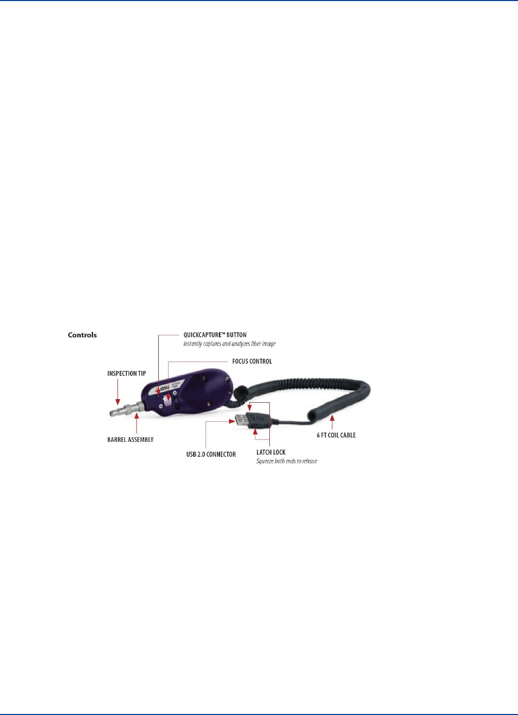
Fiber Cleaning and Inspection
Preventive Maintenance and Cleaning
18.4.1.2.
Optical Return Loss (Back Reflections)
This is easily tested by using an OTDR instrument, although the symptoms as described above can be
seen by looking at the RF output with a spectrum analyzer. The cause of poor back reflections can be
caused by:
•
Poor or incorrect connector types. APC connectors do not generally produce significant back
reflections, but with PC connectors, pay careful attention to the return loss specification and
take care when handling connectors to ensure that dirt is not present as it can also effect return
loss.
•
Tight fiber bends: If a fiber is bent too tightly then it is possible to cause internal reflections.
When installing fibers, and particularly when storing excess fiber, always observe the
minimum bend radius specified. These are easily seen with a VFL (visual fault locator). These
usually use a visible red laser which will clearly show up fiber breaks, severe bends and faulty
connectors.
•
Dirty fibers (Causing Loss and Back Reflections issues).
18.4.2. Cleaning Fibers
Clean fibers are important in all installations but in Multimode installations this is even more important.
Ideally all fibers should be visually inspected as this gives a very clear indication of dirt on fibers.
There are many optical inspection tools such as the one shown below:
With the inspection tool shown above which connects to a PC the image of the fiber can be captured
and examined prior to cleaning.
Installation and Configuration 18-3
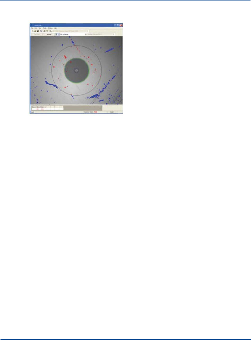
Antenna Cables and Connections
Preventive Maintenance and Cleaning
Note that special tips are required to inspect APC connectors due to the angle of the connector face.
However, the fiber must be clean enough so that <-30dB ORL threshold is maintained on the optical
link.
18.4.2.1.
Dry Cleaning
This is the most common type of cleaning method. Normally, just a single-click cleaner device is used
or the dry cloth. This method is effective for new/better maintained fibers.
18.4.2.2.
Wet Cleaning
This method is more effective on used or poorly maintained fibers which require a great deal of
cleaning. If the dirt cannot be removed by using dry cleaning methods, special wet wipes, usually
alcohol based, can be used to clean the face followed by ideally a dry wipe action such as single-click
cleaner to effectively wipe off the dirt speckles.
18.5 Antenna Cables and Connections
Remote Units Antennas and interconnecting jumper cables and connections are normally located
behind ceilings and are obscured from sight.
Occasional inspection of cable and antenna physical mounting should be undertaken as part of a
coverage or walk test every 6 months.
This should also be done following work being carried out by others in the vicinity of equipment.
18-4 Installation and Configuration
Chapter 19: Specifications
System RF Parameters
System Bandwidth
150MHz to 2700MHz
System Band Gain Flatness
±1dB
In any 100MHz band
Wide Gain Flatness
-5dB / +1 dB
250MHz to 2700MHz
Downlink
Gain
25dB (max)
1dB steps
RF Input Power to Service
Module
-25dBm (min) to +15dBm (max)
Working input power to Service
Module
RF output power at Remote
Unit Tx port
+32dBm peak
+20dBm/+18dBm RMS
For services approved to FCC/
CE regulations
Uplink
Gain
25dB (max)
1dB steps
RF input level to Remote Unit
Rx port
-20dBm
RF output power from Service
Module
-10dBm
Output power of Service Module
in Hub
Fiber Optic
Number of optical ports
Up to 8 duplex ports supported on Primary Hub (Optical Modules); 9 duplex
ports on Secondary Hub; 1 duplex port on Remote Unit; SC/APC connectors
Wavelength
1310nm
Fiber types supported
Single-mode (SM) cable 9/125 µm
Fiber distance
5dBo optical link budget, distance dependent on fiber type & quality
Laser safety classification
Class 1
Connectivity
Primary Hub
RF Service connection: 2 N-type female connectors (1 pair per Service
Module, maximum 4 Service Modules supported)
Optical interconnect (Primary Hub to Secondary Hub, or Primary Hub to
Remote Unit): duplex fiber SC/APC connector (1 per Optical Module,
maximum 8 Optical Modules supported)
10/100Base-T Ethernet connection: 1 RJ45 connector
USB2 Host connections: 2 USB type-A receptacles
RS232 Serial Terminal: 1 DE-9 male connector
Alarm Relay connections: 1 DE-9 female connector
Secondary Hub
Optical interconnect (connections to 1 Primary Hub and 8 Remote Units): 9
duplex fiber SC/APC connectors
Alarm Relay connections: 1 DE-9 female connector
Remote Unit
RF Antenna connections: 2 N-type female connectors
Optical interconnect: duplex fiber SC/APC connector
Alarm Relay connector: 1 Phoenix Contact 5.08mm 3-way male

19-1

Specifications
Physical, Electrical, and Environmental
Primary Hub
17.5” (444mm)w x17.08” (430mm)d x 5.2” (132mm)h (3U)
33.3 lbs (15.10 kg) Fully Populated
AC: 110/240V, 50/60Hz, 50-150W (depending on config)
Operating temperature (ambient non-condensing) -5 to +45 °C (23 to 113 °F)
Secondary Hub
17.5” (444mm)w x17.13” (435mm)d X 1.72” (43.7mm)h (1U)
15 lbs (6.8 kg)
AC input: 110/240V, 50/60Hz, 20-688W (depends on 48V DC output power)
DC outputs: 48V, 8 ports, 75W (max) per port
Operating temperature (ambient non-condensing) -5 to +45 °C (23 to 113 °F)
Remote Unit
12.12” (308mm)w x 2.63” (67mm)d x 8.6” (220mm)h
5.73 lbs (2.6Kg)
48V DC 0.5A / 24W from Secondary Hub or PSU
Operating temperature (ambient non-condensing) -5 to +50 °C (23 to 122 °F)
Central 48V Power Supply
Operating temperature (ambient non-condensing) -5 to +50 °C (23 to 113 °F)
1U dimensions 17.13” (435mm)w x17.3” (440mm)d X1.73” (44mm)h 1U
Weight 11.9 lbs (5.4 kg)
POI
Active 17.5” (446mm)w x14.2” (360mm)d X8.8” (222mm)h (5U)
61.7 lbs (28 kg) Fully populated
Operating temperature (ambient non-condensing) -40 to +60 °C(-40 to 1140 °F)
Small Cell 17.3” (440mm)w x14.95” (380mm)d X1.73” (44mm)h (1U)
2.5 kg (5.5 lbs)
Operating temperature (ambient non-condensing) -5 to +45 °C(23 to 113 °F)
19-2 Installation and Configuration

Chapter 20: Glossary
" Inches
A Amp
AC Alternating Current
ALC Automatic level Control
APC Angled Physical Contact
AWS Advanced Wireless Services
BDA Bi-Directional Amplifier
BTS Base Transceiver System
BW Bandwidth
CAT-5 Category 5
CE Conformity European
Coax Coaxial
Conditioning Module A Zinwave hot-swappable module inserted in a POI
Configuration GUI Zinwave’s web-based application
Control Module A Zinwave hot-swappable module inserted in a POI
DAS Distributed Antenna System
dB Decibel
dBc Decibel relative to carrier
dBm Decibel referenced to a milliwatt
dBo Decibel reference to Optical loss / gain
DC Direct Current
DL Downlink
EIAJ Electronic Industries Association of Japan
EMS Element Management System
EN European Norm
ETSI European Telecommunications Standards Institute
FCC Federal Communications Commission
FDA Food and Drug Administration
FDD Frequency Division Duplex
FSL Free Space Loss
GHz Giga Hertz
GSM Global System for Mobile Communication
HW Hardware
iDEN Integrated Digital Enhanced Network
20-1
Word Definition

Glossary
IEC International Electro technical Commission
ISM Industrial Scientific and Medical
kg Kilogram
km Kilometer
lbs American measurement in pounds
LED Light Emitting Diode
LTE Long Term Evolution
m Meter
Mains Refers to AC power
MHz Mega Hertz
MIMO multiple-input and multiple-output
mm millimeter
MM Multimode
MMF Multimode Fiber
ms millisecond
nm Nanometre
NTRL National Technical Reports Library
Optical Module A Zinwave hot-swappable module inserted in a Primary or Secondary Hub
Patch cord Zinwave provides fiber cables for use with Zinwave Equipment
Passive Module A Zinwave hot-swappable module inserted in a POI
PC Physical Contact
PCS Personal Communications System
POI Point of Interface, Zinwave has Active and Small Cell devices
Primary Hub A Zinwave Hub configured as Primary
PSU Power Supply Unit (1U and 2U available)
Remote Unit A Zinwave device that connects to an antenna
RoW Rest of World
RF Radio Frequency
RJ45 Registered Jack 45
Rx Receive
SC-APC Standard Connector/ Angled Physical Contact
Secondary Hub A Zinwave Hub configured as Secondary
Service Module A Zinwave hot-swappable module inserted in a Primary Hub
SM Singlemode
SMA Subminature Version A
SMF Singlemode Fiber
SMR Specialized Mobile Radio
SNMP Simple Network Management Protocol
20-2 Installation and Configuration
Word Definition

Glossary
TDD Time division duplex
Tma Maximum ambient temperature
Tx Transmit
UL Uplink
UMTS Universal Mobile Telecommunications System
UNItivity 5000 Zinwave’s in-building wireless solution
V
Volt
VAC Volts Alternating Current
W
Watts
WCDMA Wideband code division multiple access
Wi-Fi Wireless Fidelity
WiMAX Worldwide Interoperability for Microwave Access
WLAN Wireless Local area network
µm Micron, 1x10⁻⁶ meters
Installation and Configuration 20-3
Word Definition

Glossary
20-4 Installation and Configuration

Symbols
+ve 5 volt supply fault 16-5
Numerics
15 volt supply fault 16-5
19" rack mounting
Hub
5-2
21CFR1040 i-vi
3.3 volt supply fault 16-5
3000 HUB MODULE BLANK PLATE 5-1
48V Input Remote Unit. 2-8
89/336/EEC i-vi
9 way 2-2
A
About this Manual ii-xiii
AC Power Cord 2-3
AC power requirements 19-2
AC Powered Hub 5-5
Accessing the GUI 11-1
Active POI 1-1, 1-9, 2-12
Address Bar 11-3
B
Back Reflections 18-3
Backup
15-1
basic
11-2
Basic Configuration 10-1
Basic Install 4-1
BDA
2-4
Blank Panels 5-3
Blanking plates for unused slots 5-1
BMA RF 2-5
Bottom View
Remote Unit 2-8
BS EN 60825-1
2003 i-vi
BTS
1-6
,
2-4
C
Cabling
1-6
,
8-1
Cage nut insertion/extraction tool 5-2
Calculated input level 14-12
Calibration 8-8
Calibration error 16-2
CAT-5
2-9
CAT5
9-2
Index
advanced
11-2
AGC
15-7
AGC Mode1 15-8
Alarm Connections 16-9
Alarm Connector 2-2
Alarm Count 13-4
Alarm Handling 16-7
Alarm Handling Configuration 16-7
Alarm interface 2-11
Alarms
16-1
ALC
2-12
Angled Physical Contact 8-7
ANSI/TIA/EIA-568 i-vi
Antenna
7-1
Antenna Cables
Clean 18-4
Antenna Connections
clean 18-4
Antenna Connector Receive 2-8
Antenna Connector Transmit 2-8
Antenna Requirements 7-1
Antennas
2-8
APC
8-7
Architecture
1-4
ariable attenuation 2-12
Audience ii-xiii
Autosetup Sheet 17-9
AWG
9-2
CAT5/Power Distribution Requirements 9-2
CAT6
9-2
CE certified i-v
CE Declaration of Conformity i-x
CE Information i-x
ceiling mount 2-7
Central 48V PSU 2-9
Change equipment 14-14
Chrome
11-1
Class A Digital Device i-ix
Cleaning
18-1
Cleaning Fibers 18-3
Clearing Relays 16-7
Coax
2-8
Colors
13-3
combining/splitting function 2-12
Communications LED 3-2
Components
2-1
Configuration
1-5
Configuration Files 15-1
Configuration GUI 2-14, 11-1
Configuration has not been confirmed 16-3
Connect
Infrastructure and Other Optical Modules 9-1
Optical Modules 9-1
PSU to Remote Units 9-2
Remote Units 9-2
Service Modules Modules to POI 9-1
Service Modules to RF inputs 9-1
Connecting Antenna to Remote Units 7-4
Connecting the PSU to a Hub 9-4
I-1

Connections
9-1
Connectivity
19-1
Connectors 8-5
Consult Manual i-v
Conventions ii-xiii
conventions ii-xiii
Convert Files 17-6
Country specific power cord 5-2
CPU Indicator 3-1
Current Alarms 13-4
current software version 12-2
Current1 over limit 16-5
Current1 under limit 16-5
Current2 over limit 16-5
Current2 under limit 16-5
D
Data and Power Connector 2-5
Date
12-7
DC Input 2-8
DC Power
Remote Unit 6-3
DC Power Connection 5-6
DC power Requirements 19-2
DC Powered Hub 5-6
Declaration of Conformity i-x
Device is missing 16-2
Diagnosing Fiber connections 8-8
Diagnostics
17-1
Different power levels on uplink matrix input 16-4
dimensions
19-2
direct ethernet connection 11-1
Display Area 11-4
disposal i-vi
distribution matrix 14-7
Double Star 1-5
Downlink
19-1
downlink
7-1
Downlink Automatic Gain Control activated 16-3
Downlink has poor RF performance 16-4
downlink power has exceeded the safe limit 16-2
Downlink Sensitivity 15-8
Downlink/Uplink Balance 7-4
Dry Cleaning 18-4
D-type
2-2
E
Electric shock hazard i-v
Electrical
19-2
Electrical Static Discharge i-vi
Electricity Supply i-ii
Electricostatic Discharge Sensitive i-vi
Element Management System 2-14
EMS USB 5-2
EN 50174/50173 i-vi
EN 55022/CISPR22 i-vi
EN 60825-1
2003 i-vi
Engineering interface 2-10
Environmental
19-2
Equipment maintenance 18-1
Errors
14-10
ethernet connection 11-1
Ethernet connector 2-2
European EMC directive i-vi
Event Log 13-9, 17-3
Excel File 17-8
Explorer
11-1
F
Factory Reset of a Hub 15-3
Fan fault 16-5
Fault Relay Status trap 16-10
FCC i-vii
FCC Part 15 Class A i-vi
FDA i-vi
Features
1-4
Ferrule Type 8-5
Ferrule Types 8-6
fiber
1-6
Fiber Cleaning 18-2
Fiber Colors 8-3
Fiber Considerations i-iii
Fiber distance 19-1
Fiber Infrastructure Cabling 8-1
Fiber Inspection 18-2
Fiber Optic
spec 19-1
Fiber Optic Connectors 8-5
Fiber Patch Cords 2-8
Fiber types supported 19-1
Firefox 11-1
Firmware
12-1
Front View
Hub 2-2
Optical Module 2-6
PSU
2-10
,
2-11
Service Module 2-5
Full System Hub Upgrade 12-3
Full System Remote Unit Upgrade 12-6
Fuse
2-3
,
5-6
G
Gain
downlink
19-1
uplink
19-1
Gateway Address 12-9
Get
16-10
Glossary
20-1
Google Chrome 11-1
I-2 Installation and Configuration

Graphical User Interface 2-14, 11-1
Grounding Post
2-3
,
2-10
,
2-11
,
5-6
GUI
1-1
,
2-14
,
11-1
H
Handle
2-2
,
2-10
,
2-11
Handling Optical Fiber 8-8
Hardware Preventive Maintenance 18-1
Hardware Warning 16-4
Help ii-xiii
Help Button 11-4
horizontal separation distance 7-1
hot swappable 2-4, 2-5
https
11-1
Hub
1-1
,
2-1
AC Power 5-5
DC Power 5-6
optical module 2-5
POI to primary 2-12
Power 5-5
Service Modules primary 2-4
Status
13-3
Hub Front Panel LEDs 3-1
Hub LEDs 3-1
Hub Mounting Screws 5-1
Hub Setup 15-1
Hub Type 12-1
Hub Unit 19-1
Hub unit 19-2
Hub Upgrade
Full system 12-3
individual
12-2
I
IC compliance statement i-x
IEC 60825-2 i-vi
IEC 60950-1 i-vi
In
2-9
Individual Hub Update 12-2
Individual Remote Unit Upgrade 12-4
Informational 16-6
Infrastructure
8-1
Infrastructure and Other Optical Modules 9-1
Infrastructure Interface 8-4
Infrastructure Mode 8-2
Initial System Setup 12-1
Input level too low 16-4
Insertion Loss 18-2
insertion/extraction tool 5-2
Inspection
18-1
Install
4-1
Antenna
7-4
Blank Panels 5-3
Hubs
5-1
Optical Modules 5-4
Remote Unit 6-1
Service Module 5-4
Installation, use, and storage i-iii
Intended Audience ii-xiii
internal service distribution matrix 14-7
Interpreting System Status 13-2
IP address 11-1
IP Settings 12-8
IPv4 Address 12-9
ISO 9001 i-vi
ISO 9001certified i-v
ISO/IEC 11801 i-vi
Isolation
7-1
Isolation Measurement Techniques 7-2
L
Label
13-4
laser
2-8
,
8-2
Laser safety classification 19-1
LC
8-6
LED Remote Unit 3-5
LED start up sequence Optical 3-4
LED start-up sequence Service 3-4
LED Test ing 17-2
left LED 3-1
Left-Navigation Area 11-4
Link Calibration 8-8
Link Error 14-10
Link Quality 17-9
Link Quality For Remote Units 13-10
local AC power 2-9
Log Events to a USB 17-4
Log In 11-3
Logging to USB 17-5
Login Bar 11-4
Loss of service 16-1
LTE
1-6
M
M3 Screw driver 6-1
M6 CUP WASHER BLACK 5-1
Main Window 11-3
Maintenance
18-1
Maintenance Frequency 18-1
Manage Links 14-2
matrix
1-10
middle LED 3-1
MIMO
1-6
Misc
17-9
Mixed topology 1-5
Mode
8-2
Module LEDs 3-1
Modules
LED Test 17-2
Mounting Bracket
2-2
,
2-10
,
2-11
,
2-13
,
6-1
Installation and Configuration I-3

Mounting bracket for rack 5-1
Mounting Bracket Screw 5-1
Mounting Bracket washers 5-1
Mounting Kit
Hub
5-1
Mounting Remote Units 6-1
Mozilla Firefox 11-1
MTRJ
8-6
Multimode
8-2
,
8-3
multiple-input and multiple-output 1-6
N
network analyzer 7-2
Network Cabling 1-6
Network Connections i-v
Network Topologies 1-4
NRTL i-v
NRTL listing i-vi
Number of optical ports 19-1
O
On/Off
2-3
On/Off switch 2-10
Open Frame Rack Mounting 5-2
Optical communications fault 16-5
optical fiber 1-6
Optical Fiber connector 2-6
Optical Link 17-1
Optical Loss 8-2
Optical Module 1-1, 2-5
Optical Module LEDs 3-1
Optical Modules
Install
5-4
Optical Return Loss 18-3
Optical Safety Precautions i-iv
Optical Time Domain Reflectometer 17-1
Optional Components 1-9
OTDR
17-1
Out
2-9
overload protection 2-12
ower Cord Connector 2-3
P
password
11-2
Passwords
11-5
Patch Cords 2-8
Patch Panel 8-1
PC
8-7
Physical Contact 8-7
Physical, Electrical, and Environmental 19-2
pin out 9-3
PoE
9-2
POI
19-2
Point of Interface 2-12
Poor Optical Links 14-4
Populating Hubs 5-1
Power
Hub
5-5
Power Connector 2-10, 2-11
Power connector slots 2-10, 2-11
power cord 5-2
Power Indicator 3-1
Power LED 2-11, 3-2
Power over Ethernet 9-2
Power Supply 19-2
Power supply fault 16-5
Power Supply Unit 1-1
power supply unit 2-9
Power Switch 2-3
Powering Remote Unit 6-3
Pozi-drive screwdriver 5-2
Primary Hub 2-1, 12-1
Progress Indicator 11-4
PSU
2-9
,
6-3
PSU 13v supply fault 16-5
PSU 1U 2-11
PSU 2U 2-10
PSU 3.3v supply fault 16-5
PSU comms error 16-5
PSU setup 12-10
R
Rack Mount
Ground 9-5
Rack Mount the PSU 6-3
Rack Mounted Equipment
Maintenance 18-2
Rack Mounting i-ii
19 Inch 5-2
RAWL Plugs 6-1
Read-Only Community String 16-12
Read-Write community string 16-12
Rear View 2-10, 2-11
Hub
2-3
Optical Module 2-7
PSU
2-10
,
2-11
Secondary Hub 2-4
Service Module 2-5
receive
2-9
Regulatory i-i
Regulatory Information i-vi
Relays
16-7
Remot Unit
DC Power 6-3
Remote Unit
1-1
,
2-7
,
6-1
,
19-1
,
19-2
AC Power 6-3
LED Test 17-3
Settings
15-5
Remote Unit DC Power 13-10
Remote Unit Downlink Power 14-13
I-4 Installation and Configuration

Remote Unit LEDs 3-5
Remote Unit Status 13-4
Remote Unit Upgrade
Full system 12-6
individual
12-4
Remote Unit Uplink Power Max 14-14
Remote Unt
Antenna 7-1
Remote Update RU 12-4
Reporting
16-1
Required uplink gain is too high 16-4
Restarting the Hub 15-3
Retaining Screw 2-5
Retaining Screws 5-1
Return loss 8-2
RF Exposure i-iii
RF Input 2-5
RF input level 19-1
RF Input Power to Service Module 19-1
RF Output 2-5
RF output power
downlink 19-1
uplink
19-1
right LED 3-1
RJ45
2-8
RO
16-12
RoHS i-xi
RoHs certified i-v
RoW Regulatory Standards i-xi
RS232 Connector 2-2
RU Calculations 13-11
RU Current (A) 13-5
RU services are restricted 16-2
RU Uplink Sensitivity 15-5
Run
17-6
RW
16-12
Rx
2-8
S
Safari
11-1
Safety i-i
Safety Information i-i
SC
8-5
SC/APC
2-8
SC/PC
2-8
Screw M4 X 10 CSK POZI STL BLACK 5-1
SCREW M6x12 PAN POZI STL BLACK 5-1
SCREW THUMB 6-32X8MM PC CASE 5-1
Secondary Hub 2-3, 12-1
Security Certificate 11-2
Serial Number 13-4
service bands 7-1
service distribution matrix 1-10, 14-7
Service Indications 3-1
service isolation 7-1
Service Module 1-1, 2-4
Service Module Downlink Sensitivity 15-8
Service Module LEDs 3-1
Service Modules Install 5-4
Service Warning 16-2
Signal and Input Power i-iii
Signal Routing 2-3
signal sensitivity 15-5
Single
8-2
Single Star 1-5
Singlemode
8-3
SISO
1-6
small cell 2-4
Small Cell POI 1-1, 1-10
SNMP
16-10
SNMP Get Objects 16-10
SNMP Settings 16-11
SNMP Traps 16-11
Software Installation i-v
software version 12-2
Specifications
19-1
ST
8-5
Stand-alone Access 11-1
Start-up Sequence 3-4
Status
13-1
Status LED 3-3
Status LEDs 2-2
Service Module 2-5
Subnet Mask 12-9
SW version 13-4
Swap Optical Module 14-15
Swap Remote Unit 14-15
SwapHub 14-14
Swapping Equipment 14-14
Symbols
13-3
symbols
i-v
System Band Gain Flatness 19-1
System Bandwidth 19-1
System error 16-6
System Layout 13-8
System Layout File to Excel 17-6
System Layout Sheet 17-8
System Layout Tables 17-5
System Overview 1-1
System RF Parameters 19-1
System Setup 14-1
System Status 13-1
System Tools 13-7
System Values 14-5
system_layout.dmp
17-6
SystemLayout_Gen.xlsm
17-6
T
Tables
17-9
Temperature 13-4
Termination Splice Box 8-1
Testing 17-1
Installation and Configuration I-5

The downlink power is above the limit 16-6
The downlink power is below the limit 16-6
The module temperature is above the limit 16-5
The requested composite power could not be
achieved 16-3
The uplink power is above the upper limit 16-6
The uplink power is below the lower limit 16-6
TIA 568 2-9
Time
12-7
Timeouts
11-5
TLS
12-8
Top View
Remote Unit 2-8
Topologies
1-4
transmit
2-9
transmit direction 8-2
Transport Layer Security 12-8
Traps 16-10
Tx
2-8
Type
13-4
U
UL certified i-v
UL gain setting too high 16-4
UL-60950-1 i-vi
Ultra-polished Physical Contact 8-7
Unit
13-4
UPC
8-7
Update
Firmware 12-1
Uplink
19-1
uplink
7-1
Uplink Automatic Gain Control activated 16-3
Uplink gain is limited 16-4
Uplink has poor RF performance 16-3
uplink power has exceeded the safe limit 16-2
Uplink/Downlink Balance 7-4, 14-11
USB
5-2
USB Connector
2-2
,
2-10
,
2-11
USB Port i-v
User Interface Settings 12-8
User Passwords 11-5
username
11-2
V
Validate
14-9
-ve 5 volt supply fault 16-5
viewer
11-2
Voltage 1(V) 13-5
Voltage1 over limit 16-5
Voltage1 under limit 16-5
Voltage2 over limit 16-5
Voltage2 under limit 16-5
W
wall mount 2-7
Warning Indicator 3-1
Warnings 14-10
waste i-vi
Wavelength 19-1
Web browser 11-1
WEEE i-vi
weight
19-2
Wet Cleaning 18-4
Wide Gain Flatness 19-1
Windows
11-1
Windows Explorer 11-1
Z
Zinwave Patch Cord 2-6
I-6 Installation and Configuration