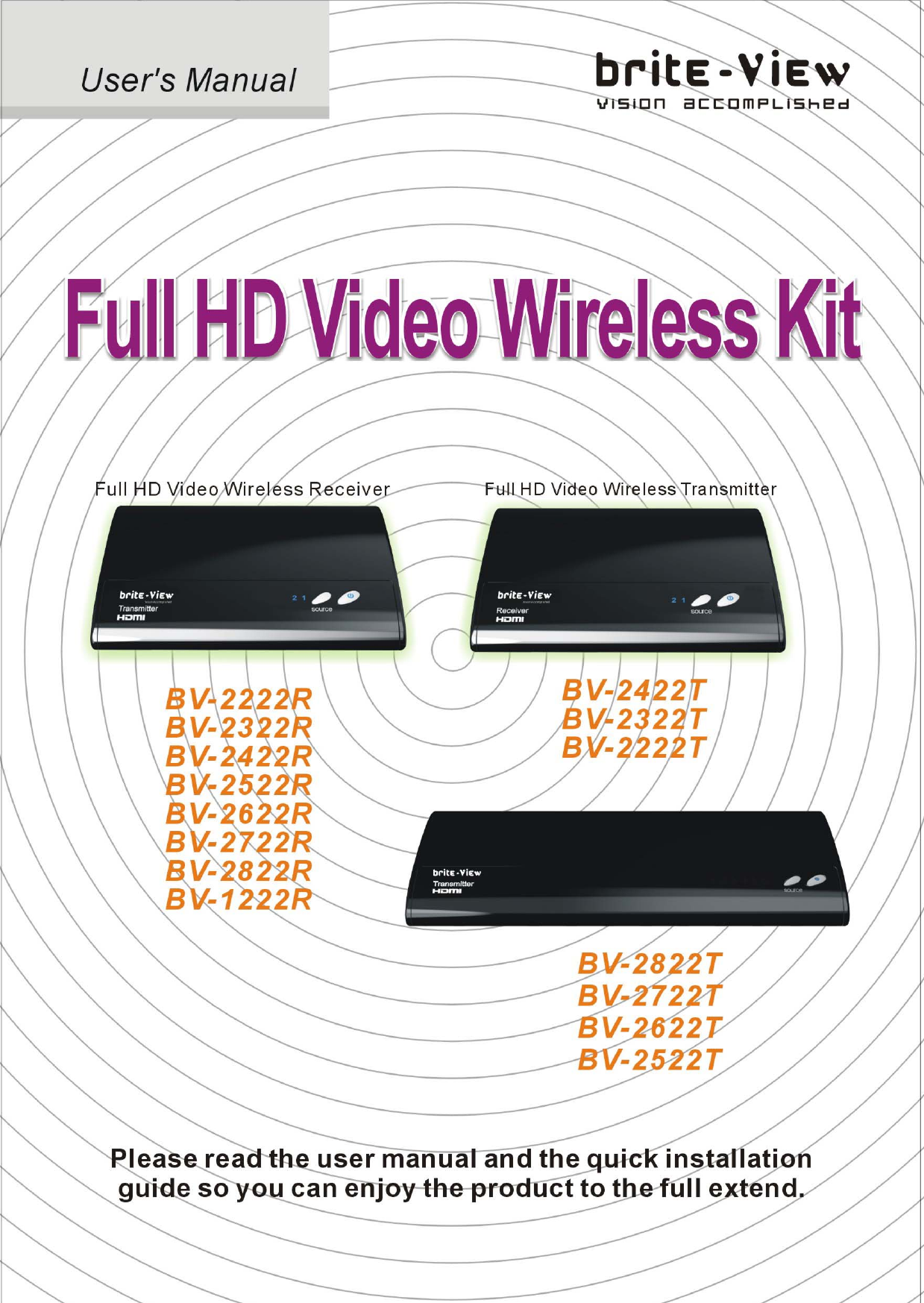
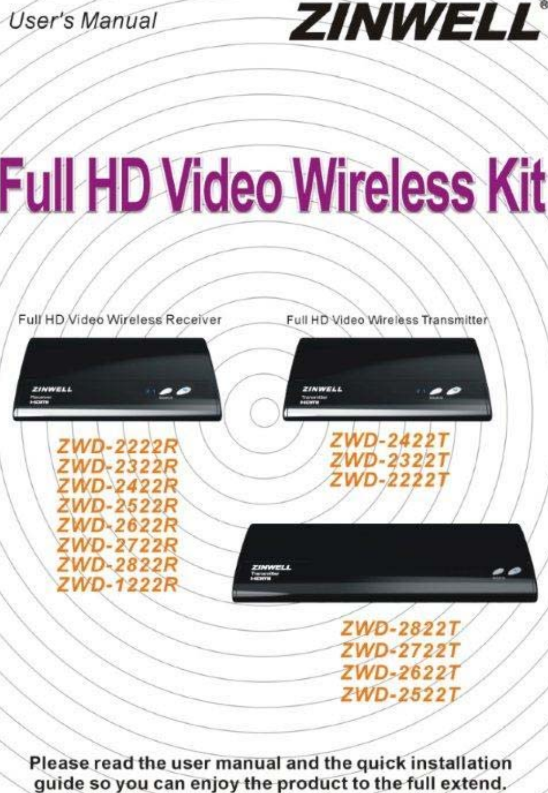
Zinwell ZRF32100 Full HD Video Wireless Reciever Module User Manual ZRF 32100 System UserMan20101220
Zinwell Corporation Full HD Video Wireless Reciever Module ZRF 32100 System UserMan20101220
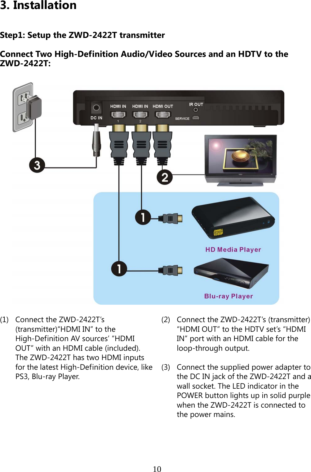
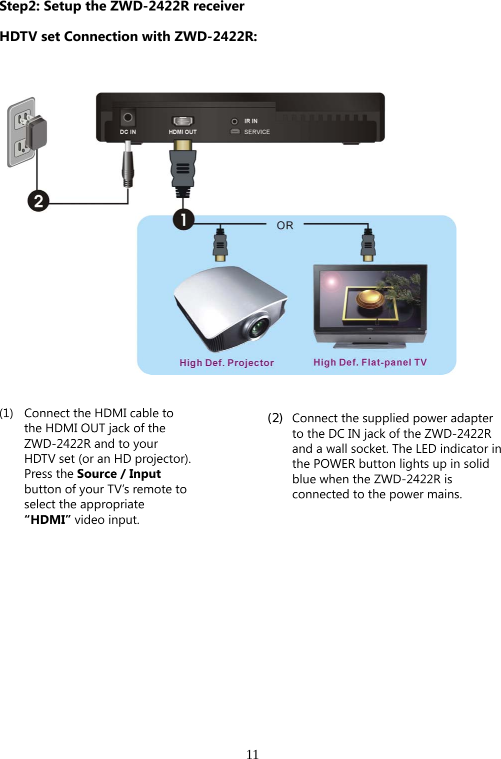
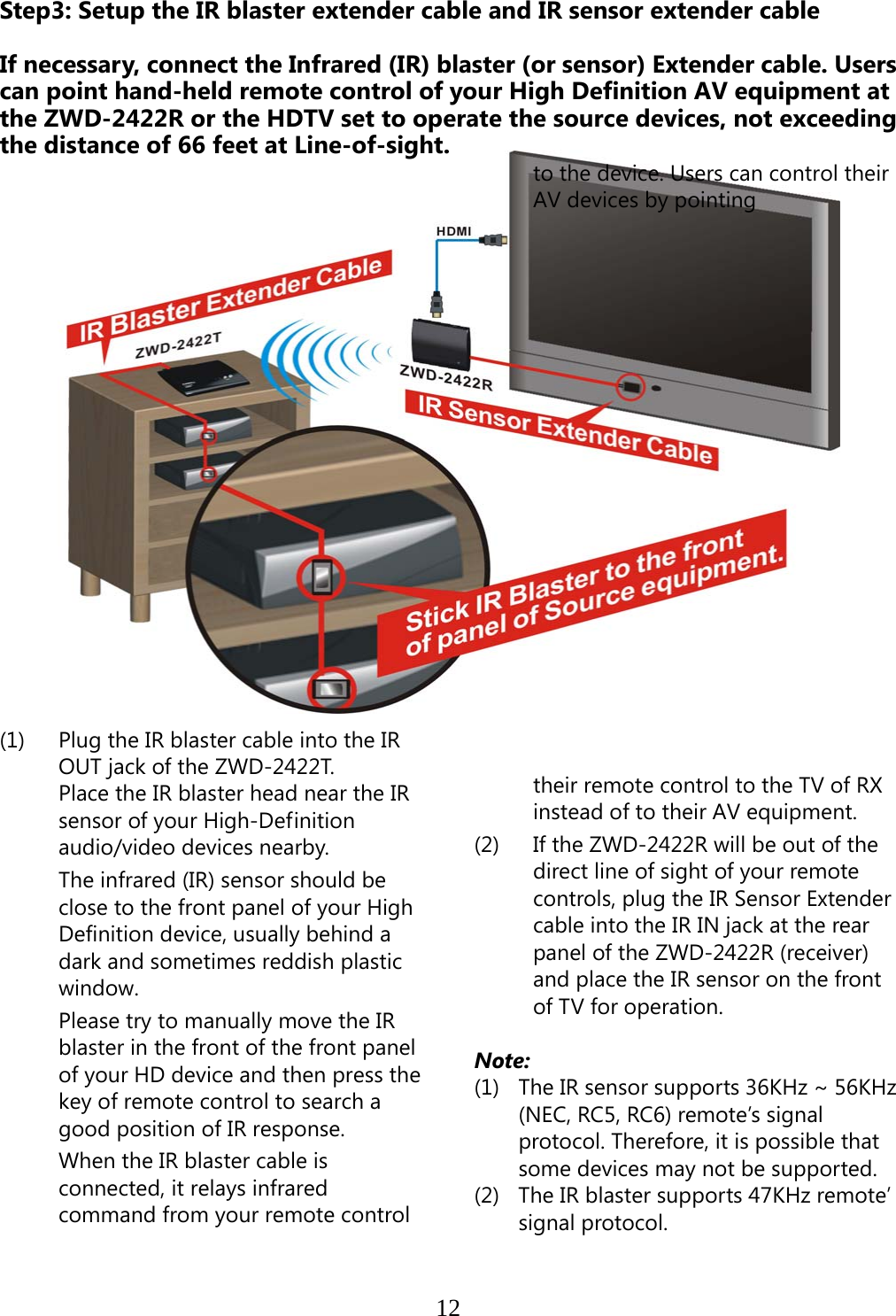
Zinwell >
Contents
- 1. Userman
- 2. (ZRF-32100) UserMan
- 3. (ZRF-32100) System UserMan_2010-10-19
- 4. ZRF 32100 System UserMan20101220
ZRF 32100 System UserMan20101220
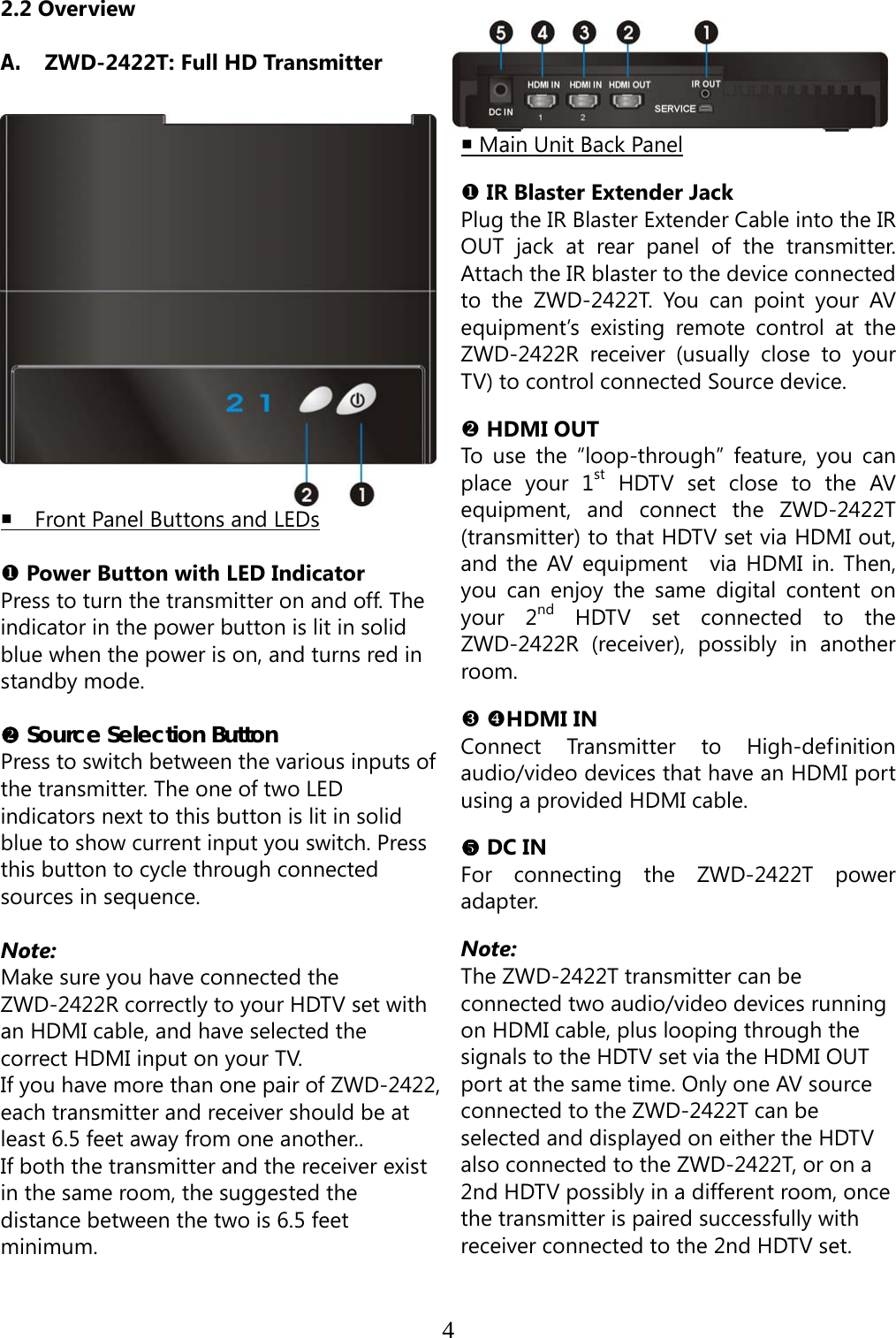
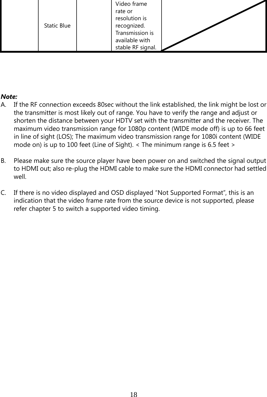
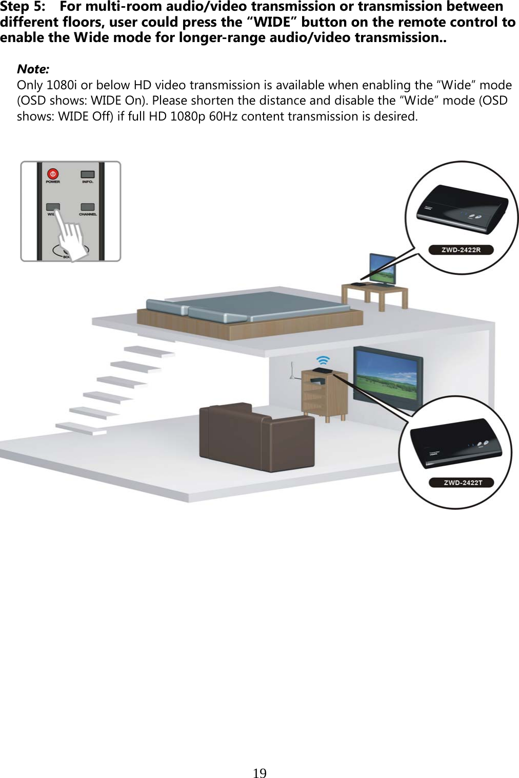
![3 STATE CITY LONGITUDE LATITUDE FREQUENCY TERRAIN ELEVATION (MSL) [ft] ANTENNA HEIGHT ABOVE TERRAIN [ft] AZ PHOENIX W 112 09 46 N 33 25 14 5610 MHz 1024 64 CO DENVER W 104 31 35 N 39 43 39 5615 MHz 5643 64 FL FT LAUDERDALE W 080 20 39 N 26 08 36 5645 MHz 7 113 FL MIAMI W 080 29 28 N 25 45 27 5605 MHz 10 113 FL ORLANDO W 081 19 33 N 28 20 37 5640 MHz 72 97 FL TAMPA W 082 31 04 N 27 51 35 5620 MHz 14 80 FL WEST PALM BEACH W 080 16 23 N 26 41 17 5615 MHz 20 113 GA ATLANTA W 084 15 44 N 33 38 48 5615 MHz 962 113 IL MCCOOK W 087 51 31 N 41 47 50 5615 MHz 646 97 IL CRESTWOOD W 087 43 47 N 41 39 05 5645 MHz 663 113 IN INDIANAPOLIS W 086 26 08 N 39 38 14 5605 MHz 751 97 KS WICHITA W 097 26 13 N 37 30 26 5603 MHz 1270 80 KY COVINGTON CINCINNATI W 084 34 48 N 38 53 53 5610 MHz 942 97 KY LOUISVILLE W 085 36 38 N 38 02 45 5646 MHz 617 113 LA NEW ORLEANS W 090 24 11 N 30 01 18 5645 MHz 2 97 MA BOSTON W 070 56 01 N 42 09 30 5610 MHz 151 113 MD BRANDYWINE W 076 50 42 N 38 41 43 5635 MHz 233 113 MD BENFIELD W 076 37 48 N 39 05 23 5645 MHz 184 113 MD CLINTON W 076 57 43 N 38 45 32 5615 MHz 249 97 MI DETROIT W 083 30 54 N 42 06 40 5615 MHz 656 113 MN MINNEAPOLIS W 092 55 58 N 44 52 17 5610 MHz 1040 80 MO KANSAS CITY W 094 44 31 N 39 29 55 5605 MHz 1040 64 MO SAINT LOUIS W 090 29 21 N 38 48 20 5610 MHz 551 97 MS DESOTO COUNTY W 089 59 33 N 34 53 45 5610 MHz 371 113 NC CHARLOTTE W 080 53 06 N 35 20 14 5608 MHz 757 113 NC RALEIGH DURHAM W 078 41 50 N 36 00 07 5647 MHz 400 113 NJ WOODBRIDGE W 074 16 13 N 40 35 37 5620 MHz 19 113 NJ PENNSAUKEN W 075 04 12 N 39 56 57 5610 MHz 39 113 NV LAS VEGAS W 115 00 26 N 36 08 37 5645 MHz 1995 64 NY FLOYD BENNETT FIELD W 073 52 49 N 40 35 20 5647 MHz 8 97 OH DAYTON W 084 07 23 N 40 01 19 5640 MHz 922 97 OH CLEVELAND W 082 00 28 N 41 17 23 5645 MHz 817 113 OH COLUMBUS W 082 42 55 N 40 00 20 5605 MHz 1037 113 OK AERO. CTR TDWR #1 W 097 37 31 N 35 24 19 5610 MHz 1285 80 OK AERO. CTR TDWR #2 W 097 37 43 N 35 23 34 5620 MHz 1293 97 OK TULSA W 095 49 34 N 36 04 14 5605 MHz 712 113 OK OKLAHOMA CITY W 097 30 36 N 35 16 34 5603 MHz 1195 64 PA HANOVER W 080 29 10 N 40 30 05 5615 MHz 1266 113 PR SAN JUAN W 066 10 46 N 18 28 26 5610 MHz 59 113 TN NASHVILLE W 086 39 42 N 35 58 47 5605 MHz 722 97 TX HOUSTON INTERCONTL W 095 34 01 N 30 03 54 5605 MHz 154 97 TX PEARLAND W 095 14 30 N 29 30 59 5645 MHz 36 80 TX DALLAS LOVE FIELD W 096 58 06 N 32 55 33 5608 MHz 541 80 TX LEWISVILLE DFW W 096 55 05 N 33 03 53 5640 MHz 554 31 UT SALT LAKE CITY W 111 55 47 N 40 58 02 5610 MHz 4219 80 VA LEESBURG W 077 31 46 N 39 05 02 5605 MHz 361 113 WI MILWAUKEE W 088 02 47 N 42 49 10 5603 MHz 820 113](https://usermanual.wiki/Zinwell/ZRF32100.ZRF-32100-System-UserMan20101220/User-Guide-1394910-Page-9.png)
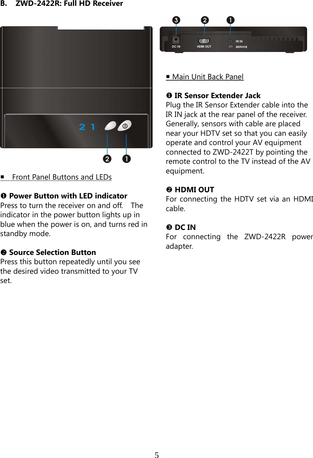
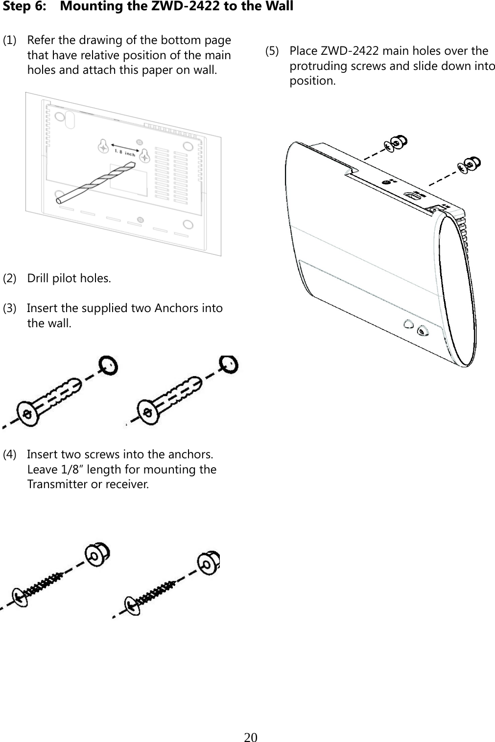
![8 Press the SOURCE button on the RCU or on the top of transmitter (or receiver) for audio/video source input selection. OSD Displayed: ▃▆█ [HDMI1] CH10 WIDE Off 1280x1024 or ▃▆█ [HDMI2] CH10 WIDE Off 1280x1024 Press the CHANNEL button on the RCU to manually switch wireless channels if the user experiences video noise. Press “Channel” button once for current Channel status displayed on the OSD : ▃▆█ HDMI1 [CH10] WIDE Off 1280x1024 Press again to change Channel Press the “Channel” button again within 5 seconds to switch Channel manually. ▃▆█ HDMI1 [CH 8] WIDE Off 1280x1024 Press again to change Channel Press the WIDE button of RCU for longer distance transmission of audio/video contents. (1) Press once for current WIDE mode status displayed on the OSD (Default is disable): ▃▆█ HDMI1 CH10 [WIDE Off] 1280x1024 Press again to switch WIDE mode](https://usermanual.wiki/Zinwell/ZRF32100.ZRF-32100-System-UserMan20101220/User-Guide-1394910-Page-15.png)
![9 (2) Press WIDE button again within 5seconds to switch WIDE mode status, OSD Displayed: ▃▆█ HDMI1 CH10 [WIDE On] 1280x1024 Press again to switch WIDE mode NOTE: Only the status of the ZWD-2422R (receiver) connected to the HDTV can be displayed on the OSD. The status of the ZWD-2422T (transmitter) HDMI out cannot be displayed.](https://usermanual.wiki/Zinwell/ZRF32100.ZRF-32100-System-UserMan20101220/User-Guide-1394910-Page-16.png)
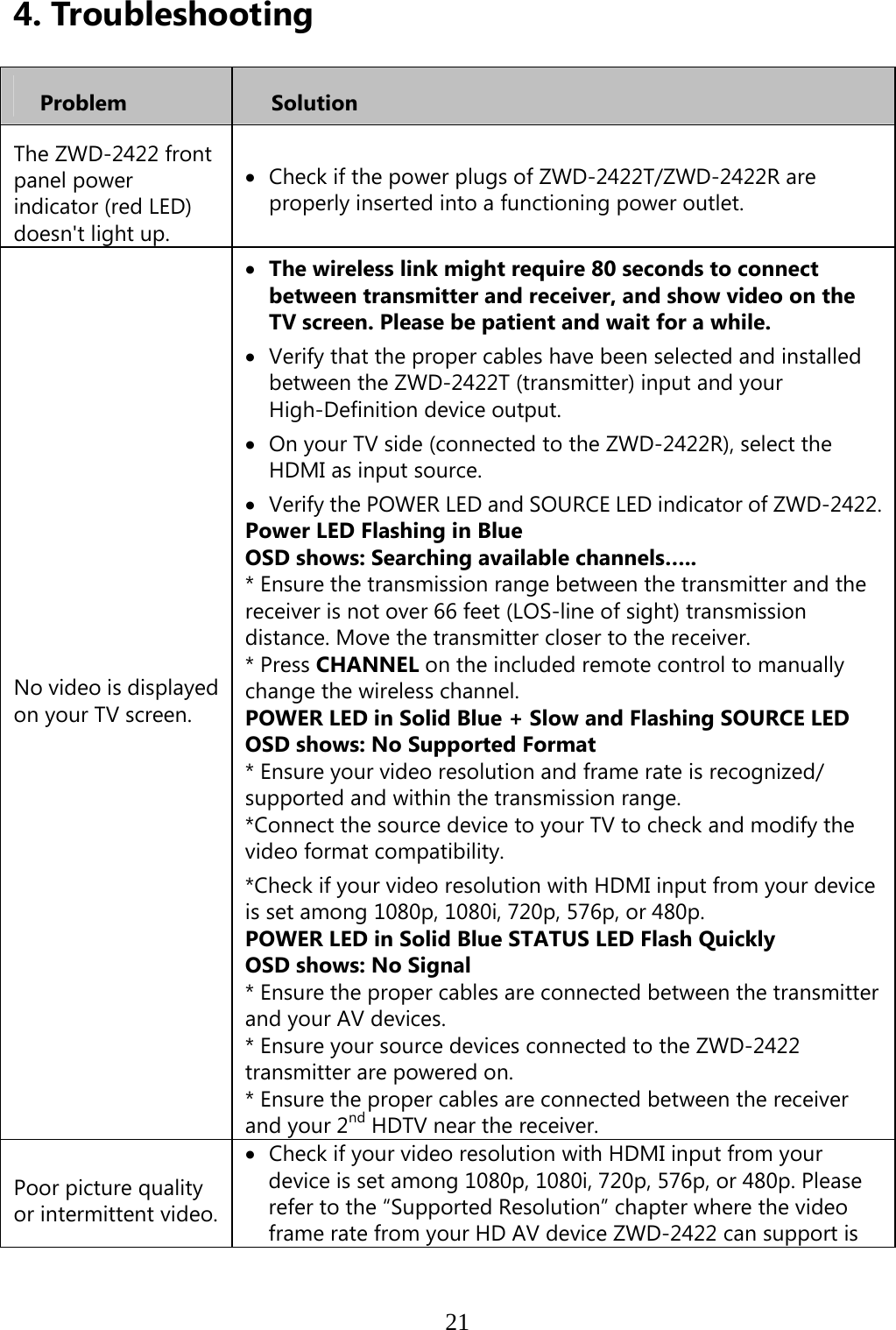
![15 (6) Press the Source button until you see the video being broadcasted from your device. (7) If you have electronic devices such as a cordless phone, wireless access point/ router sharing the 5GHz channel frequency, when you use it near the ZWD-2422, you may experience disturbed picture or diminished sound quality. Press the CHANNEL button on the remote control to change the ZWD-2422 to different channels. Note: A. Changing the ZWD-2422 to a different wireless channel: 1. Enter the wireless RF channel adjustment mode 2. Changes to the next available RF wireless channel 3. Exit the wireless RF channel adjustment modeMethod Press the CHANNEL button on the Remote Control Unit (RCU) for current channel status display. Press the CHANNEL button on the RCU again within 5 seconds to switch channel randomly. No button is pressed for 5 seconds. OSD Display Status ▃▆█ HDMI1 [CH 8] WIDE Off 1280x1024 Press again to change Channel Exit.](https://usermanual.wiki/Zinwell/ZRF32100.ZRF-32100-System-UserMan20101220/User-Guide-1394910-Page-22.png)
![16B. Channel Number Indicating the Wireless Frequency: US (DFS) Europe (DFS) Japan (DFS) WIDE mode Off Frequency [MHz] Support Region Channel Support Region Channel Support Region Channel5190 V 1 V 1 V 1 5230 V 2 V 2 V 2 5270 V 3 V 3 V 3 5310 V 4 V 4 V 4 5510 V 5 V 5 V 5 5550 V 6 V 6 V 6 5590 X X X X X X 5630 X X X X X X 5670 V 7 V 7 V 7 5755 V 8 X X X X 5795 V 9 X X X X US (Non-DFS) Europe (Non-DFS) Japan (Non-DFS) WIDE mode ON Frequency [MHz] Support Region Channel Support Region Channel Support Region Channel5160 X X X X X X 5180 V* 1 V 1 V 1 5200 V* 2 V 2 V 2 5220 V* 3 V 3 V 3 5240 V* 4 V 4 V 4 5260~5700 X X X X X X 5745 V 5 X X X X 5765 V 6 X X X X 5785 V 7 X X X X 5805 V 8 X X X X 5825 V 9 X X X X Note : A. Gray background indicates the DFS region. B. * Means “Limited to indoor use”. C. Unused Weather Satellite Channels on DFS: i. WIDE mode OFF: Center Frequency 5590MHz, 5630MHz ii. WIDE mode On: Center Frequency 5600MHz, 5620MHz, 5640MHz](https://usermanual.wiki/Zinwell/ZRF32100.ZRF-32100-System-UserMan20101220/User-Guide-1394910-Page-23.png)
![22defined. Press CHANNEL on ZWD-2422 remote control to manually change the wireless channel. Ensure the transmission distance is less than 66 feet (LOS). No audio. Check your TV’s volume is properly set and not set in "MUTE" mode. Check if the audio connectors are properly connected. Ensure the bit rate of audio from the source device can be supported by ZWD-2422. Please refer to the details in Chapter 6 Audio Bit Rate Support. No Supported Video /Audio on WIDE mode only. Check the HDMI output setting of Source device, set up HDMI output format to Auto mode instead of 1080p. Check Chapter 5 Supported resolution. Some resolution can’t be supported on WIDE mode on. IR Blaster can’t control Source device. Check where is IR sensor of Source device. Make sure IR Blaster sensor is close and straight to Source device’s IR sensor. Please refer Chapter 3, step 3 for reference setup. Change IR Blaster frequency to meet Source device’s requirement. Please continue pressing Source key on the top of Receiver only over 3secs to switch IR Blaster frequency 47K to 58K to 38K recurring. - The OSD shows: (Display 5secs) ▃▆█ HDMI1 CH10 WIDE Off 1280x1024 IR Blaster Frequency [47KHz] Press Source key on the top of Receiver again to switch IR Blaster frequency.](https://usermanual.wiki/Zinwell/ZRF32100.ZRF-32100-System-UserMan20101220/User-Guide-1394910-Page-29.png)