Zinwell ZW-2000 2.4G OutDoor Device User Manual ZW 2000 Manual 0727
Zinwell Corporation 2.4G OutDoor Device ZW 2000 Manual 0727
UserManual.wiki
>
Zinwell
>
ZW-2000 User Manual
>
Users Manual 1
Contents
1.
Users Manual 1
2.
Users Manual 2
3.
Users Manual 3
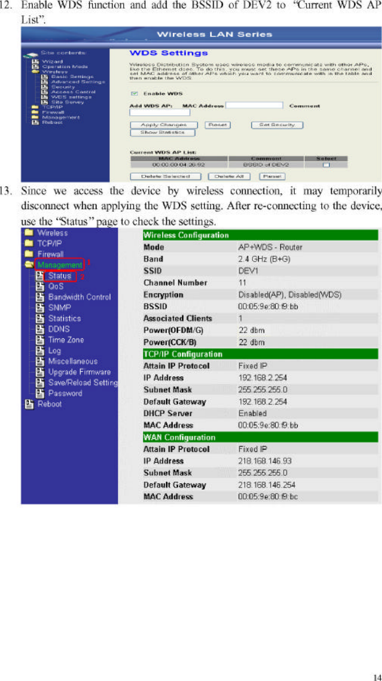
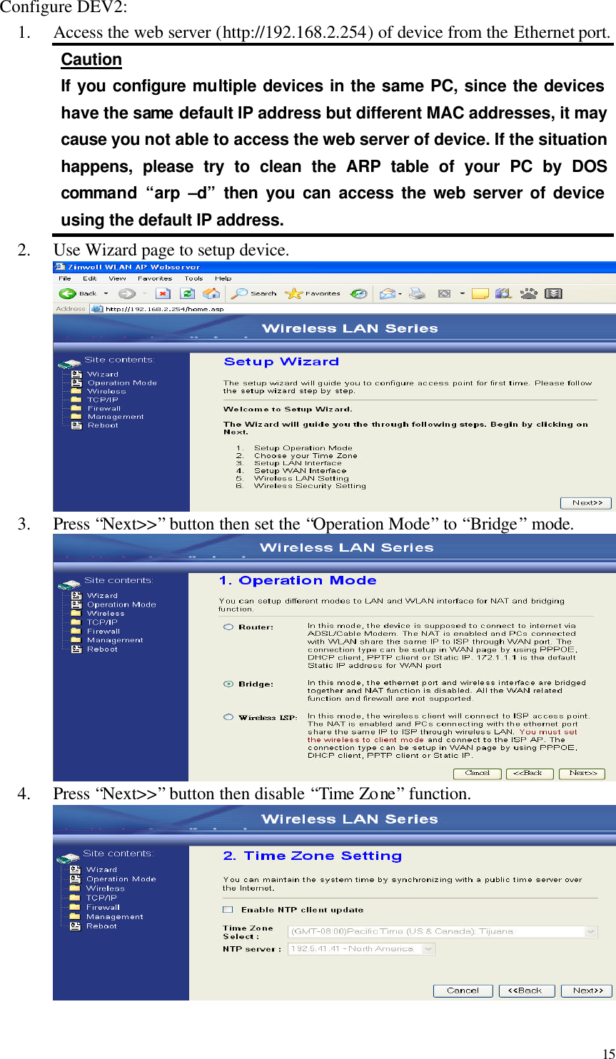
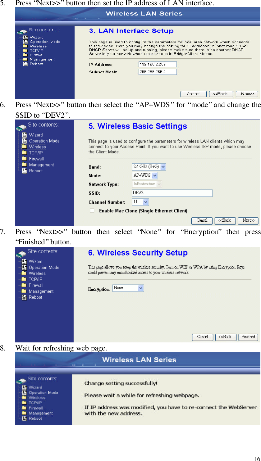
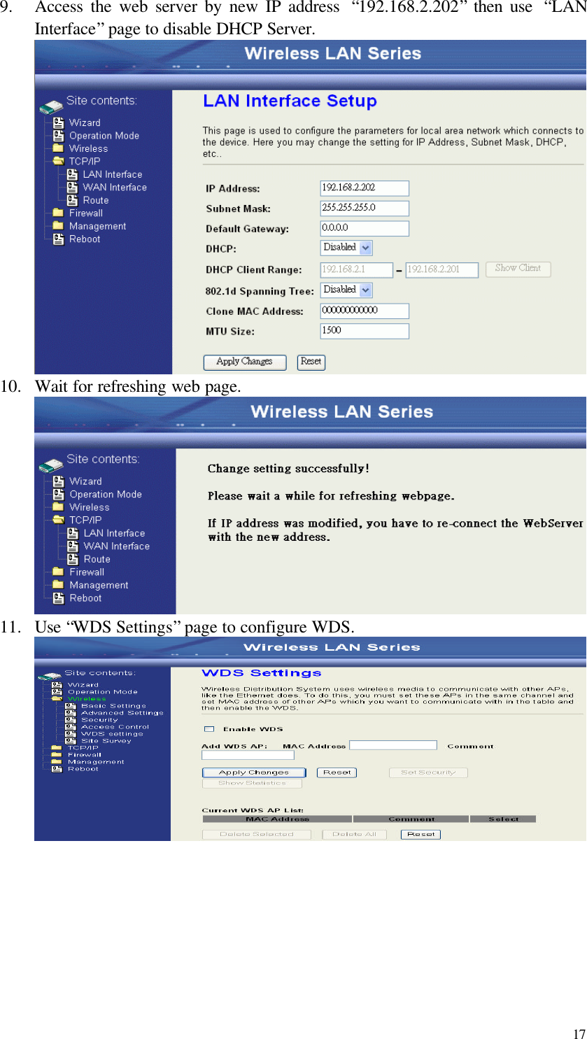
Users Manual 1
Navigation menu
Upload a User Manual
Namespaces
Wiki Guide
HTML
PDF
Info
Views
User Manual
Discussion / Help
Navigation