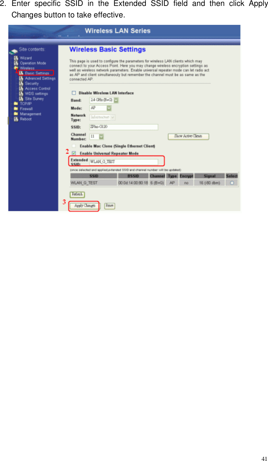
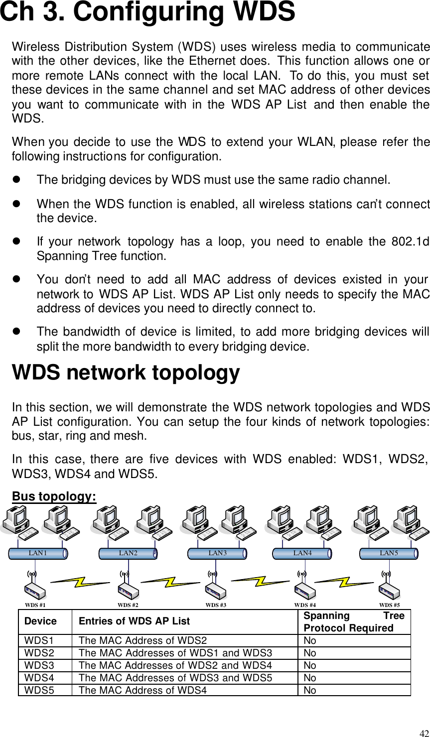
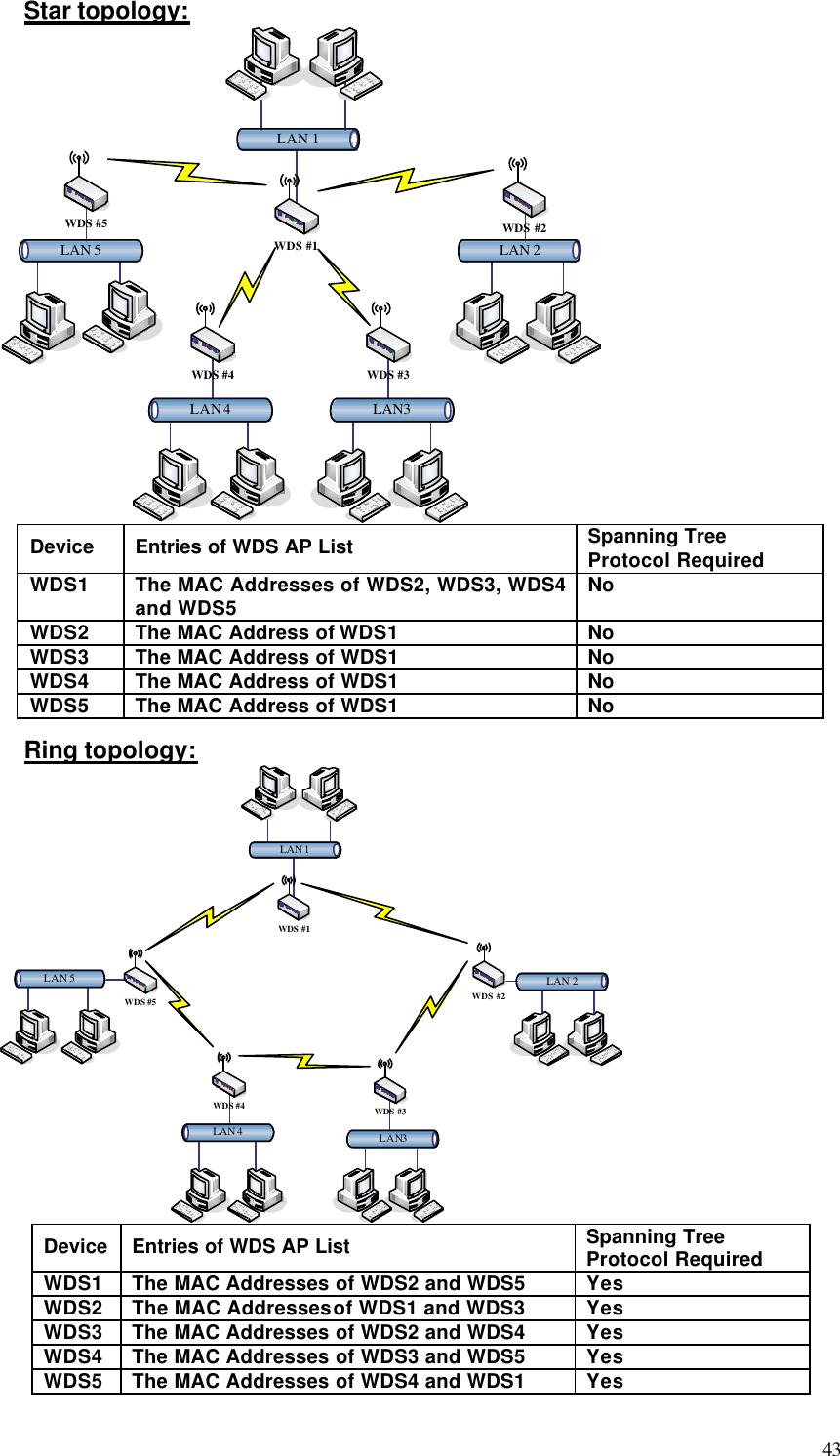
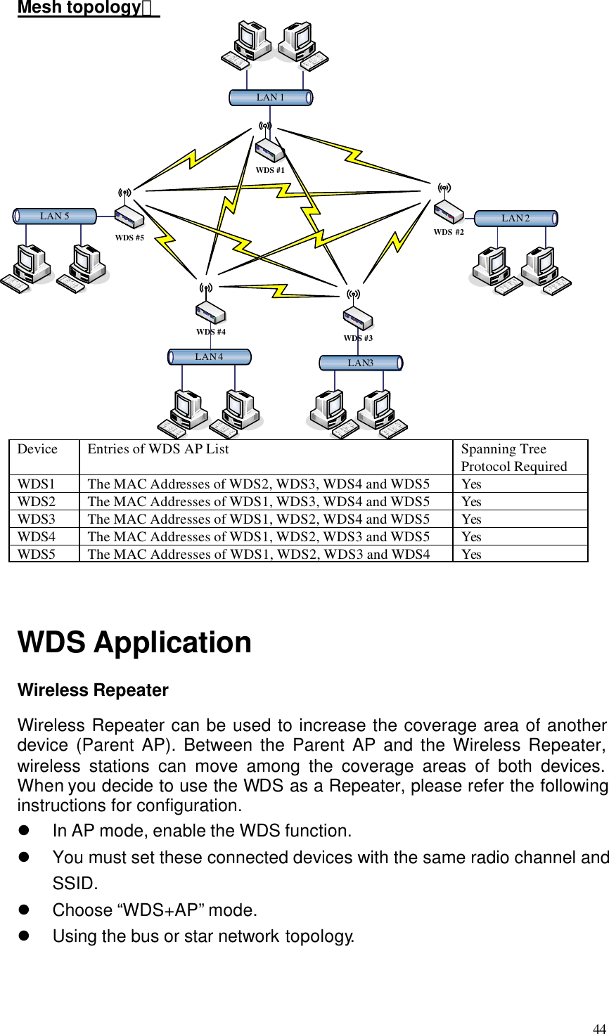
Zinwell ZW-2000 2.4G OutDoor Device User Manual ZW 2000 Manual 0727
Zinwell Corporation 2.4G OutDoor Device ZW 2000 Manual 0727
UserManual.wiki
>
Zinwell
>
ZW-2000 User Manual
>
Users Manual 3
Contents
1.
Users Manual 1
2.
Users Manual 2
3.
Users Manual 3
Users Manual 3
Navigation menu
Upload a User Manual
Namespaces
Wiki Guide
HTML
PDF
Info
Views
User Manual
Discussion / Help
Navigation
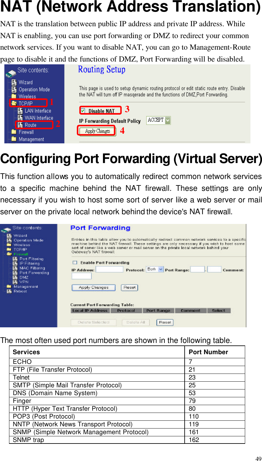
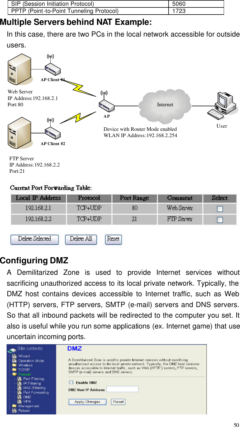
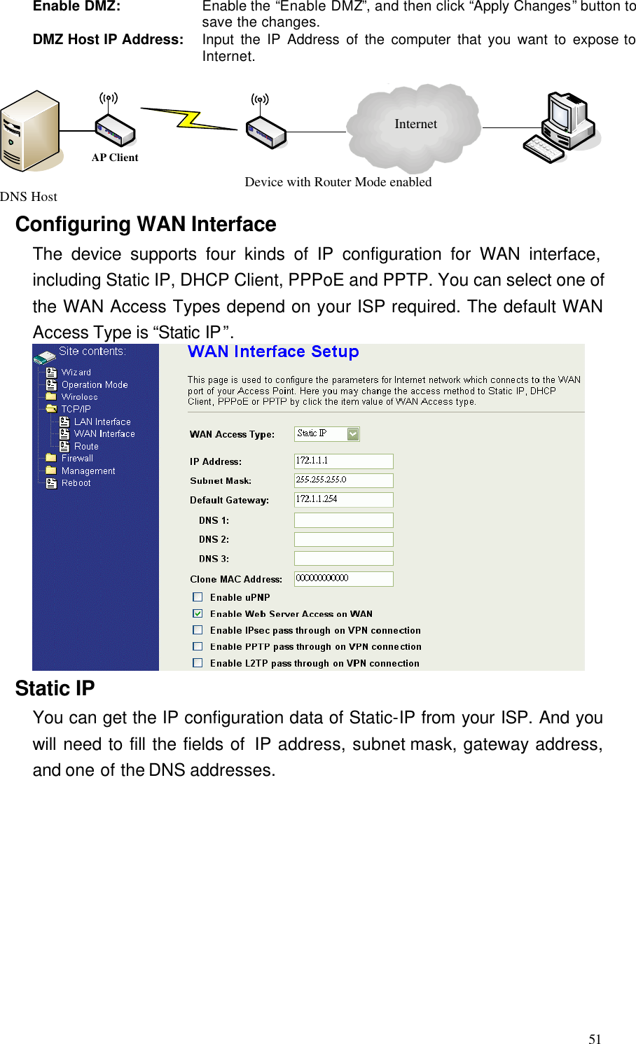
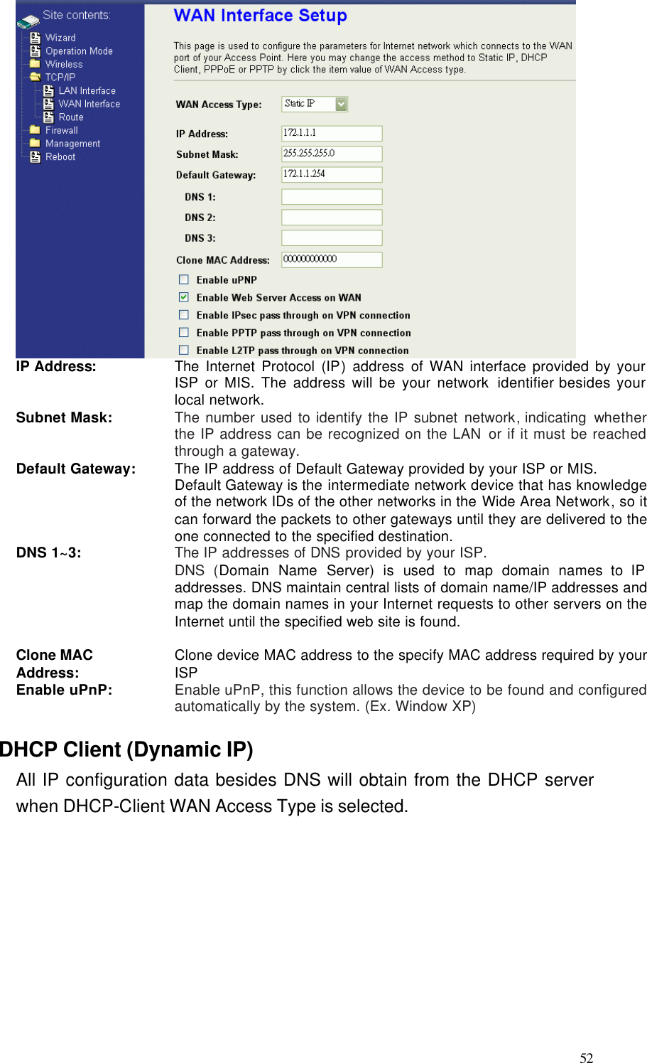
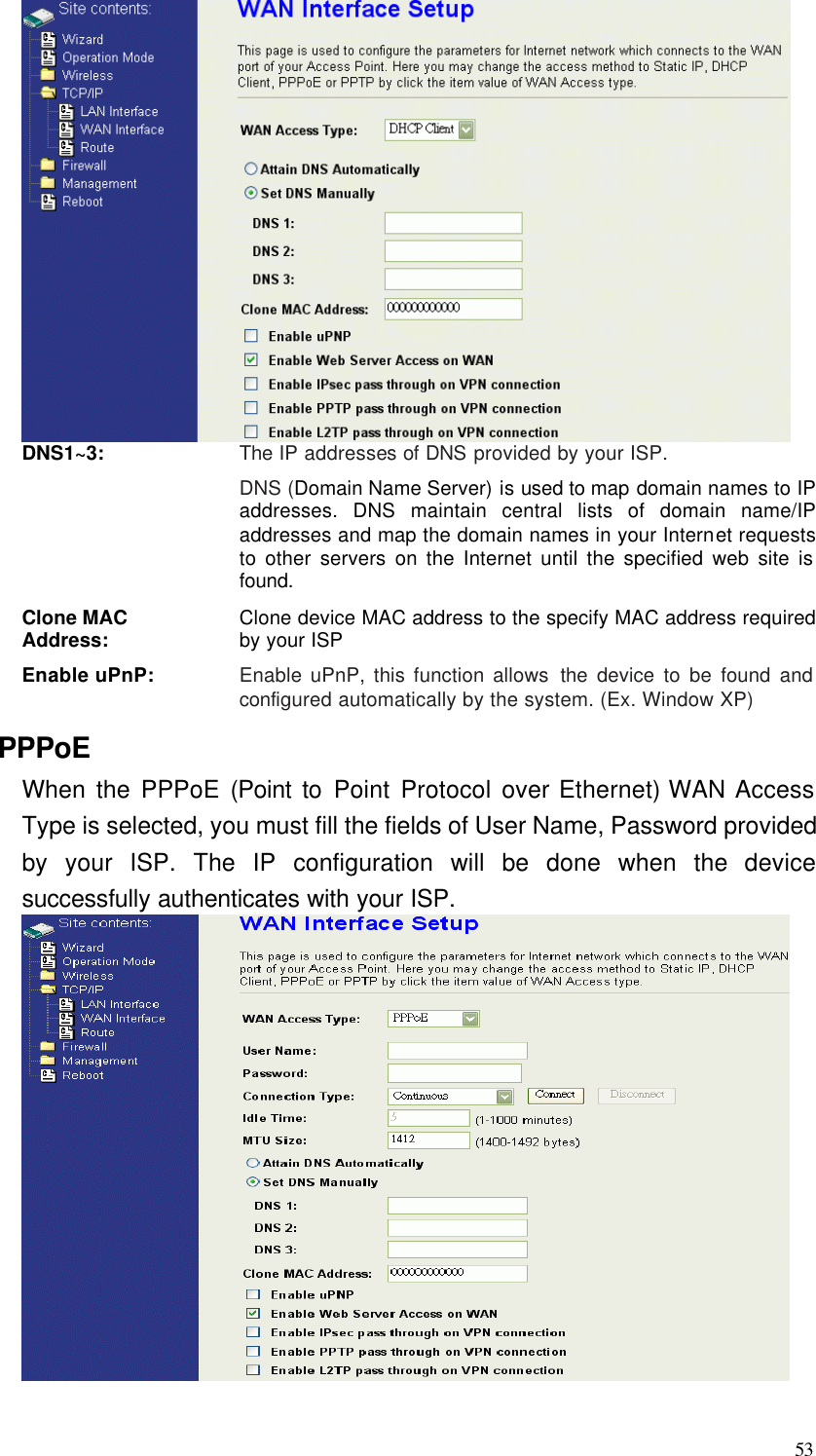
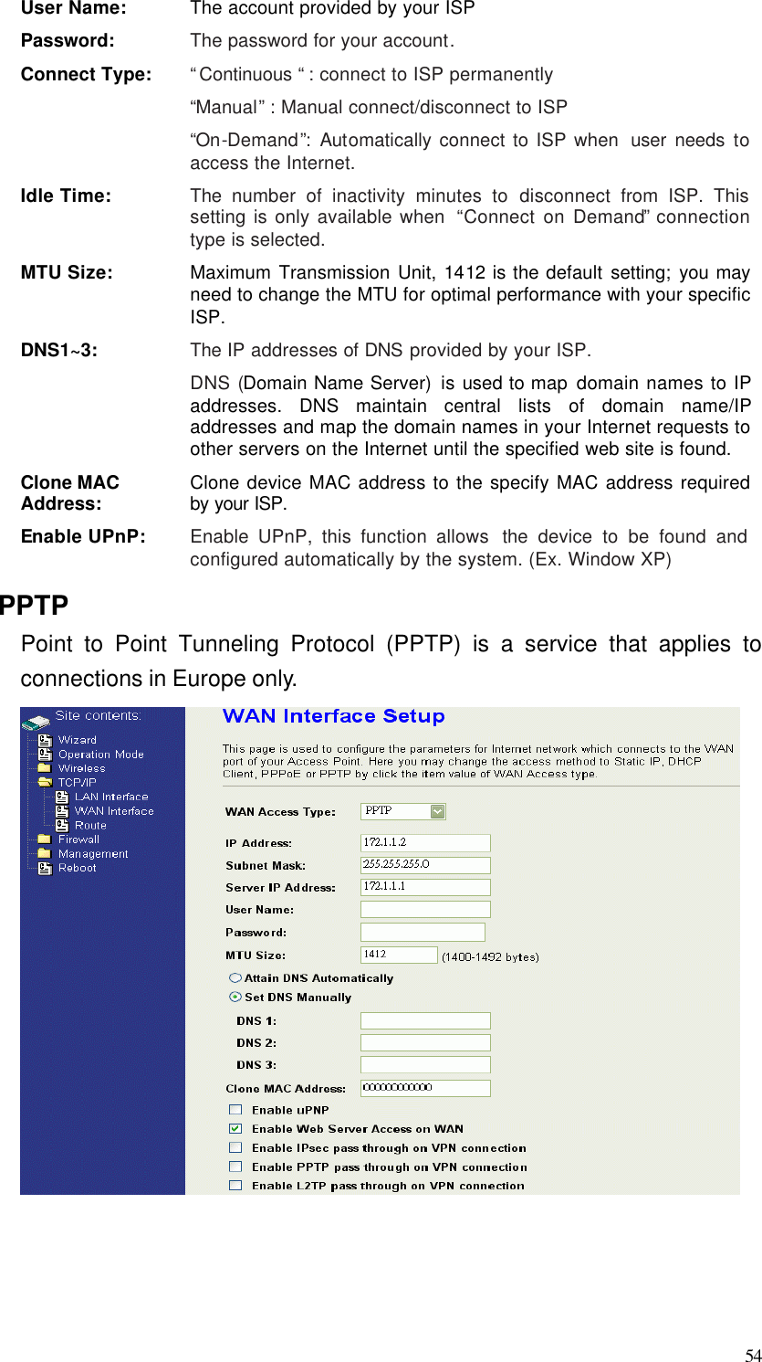
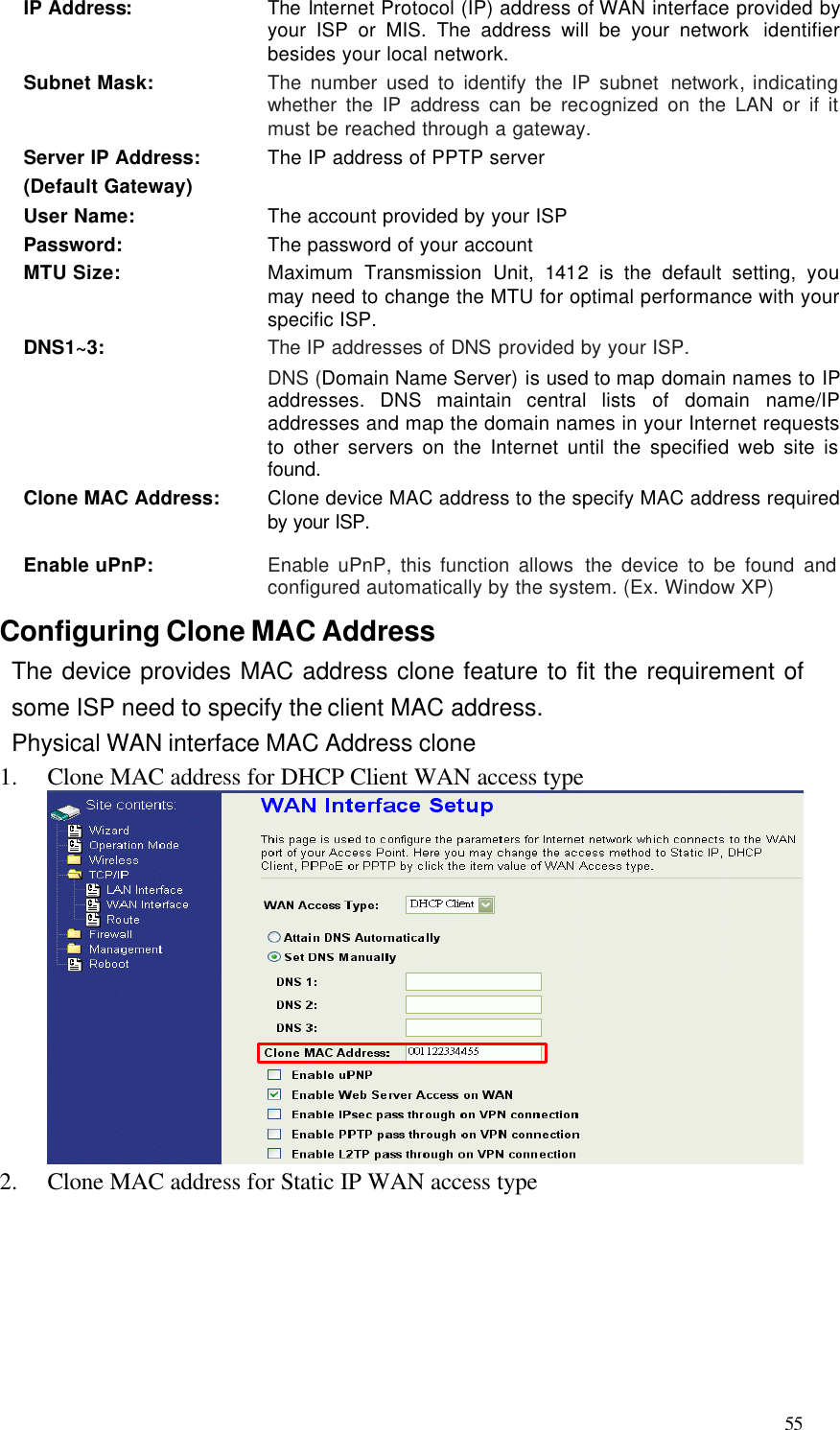
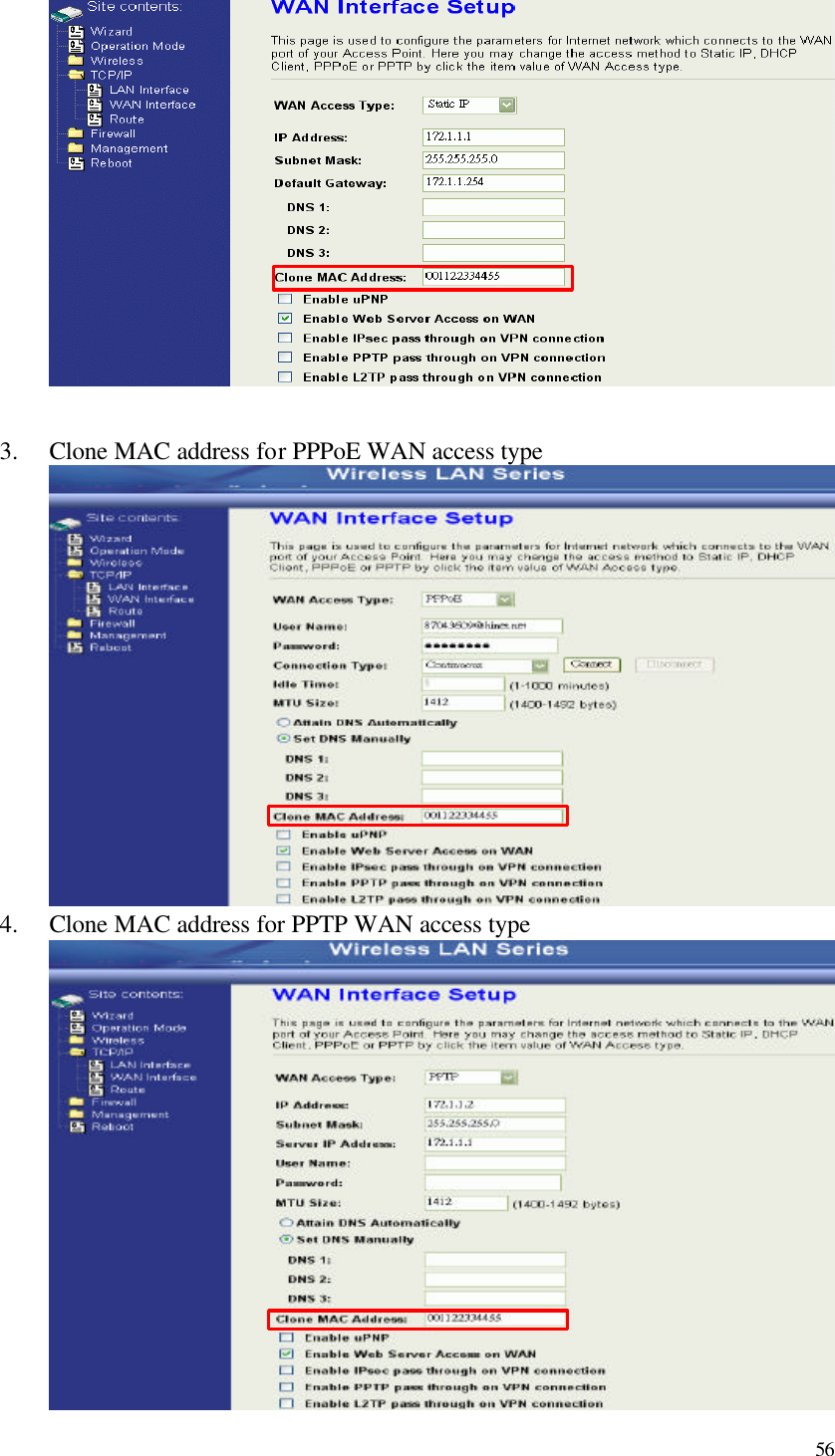
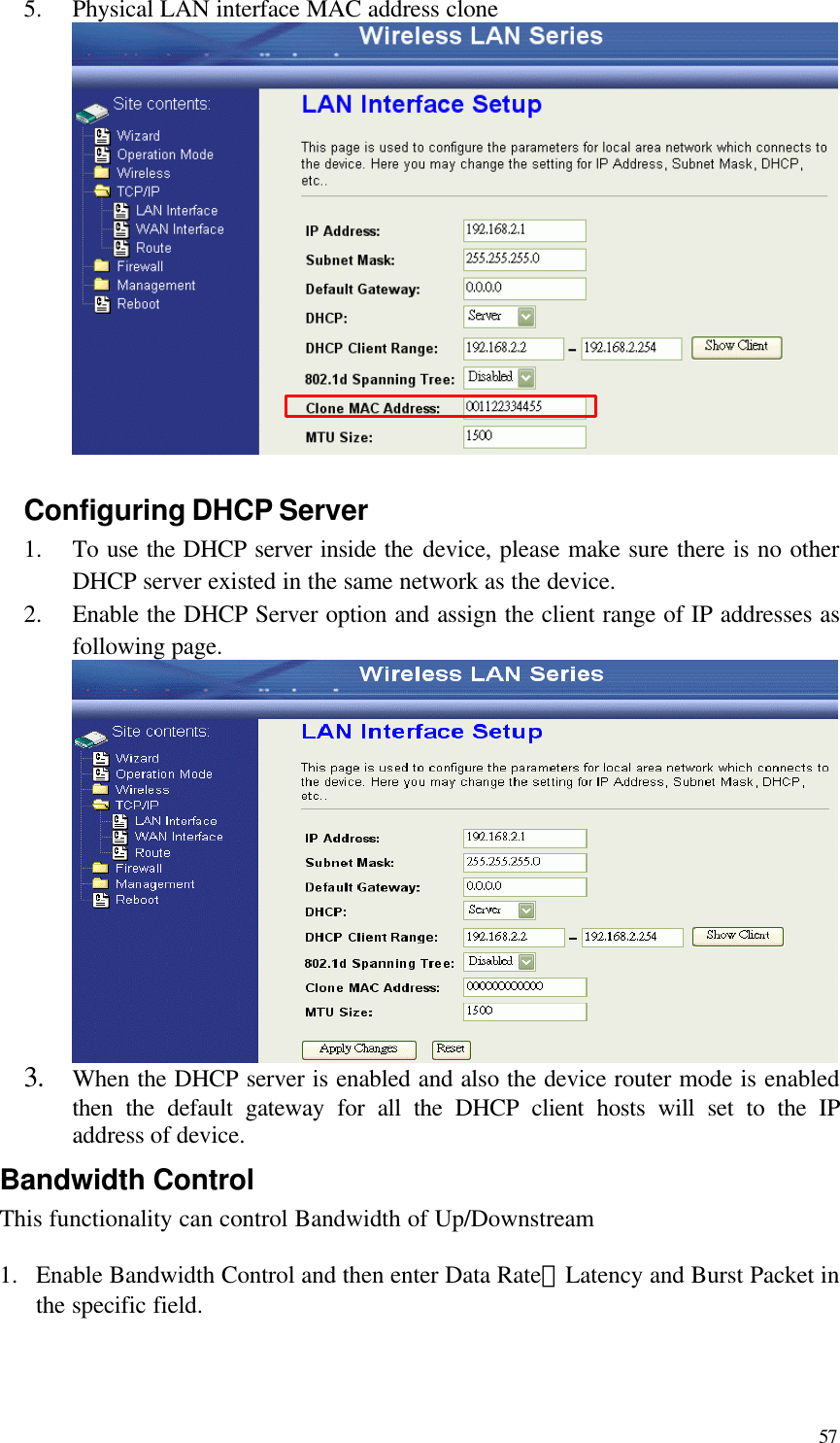
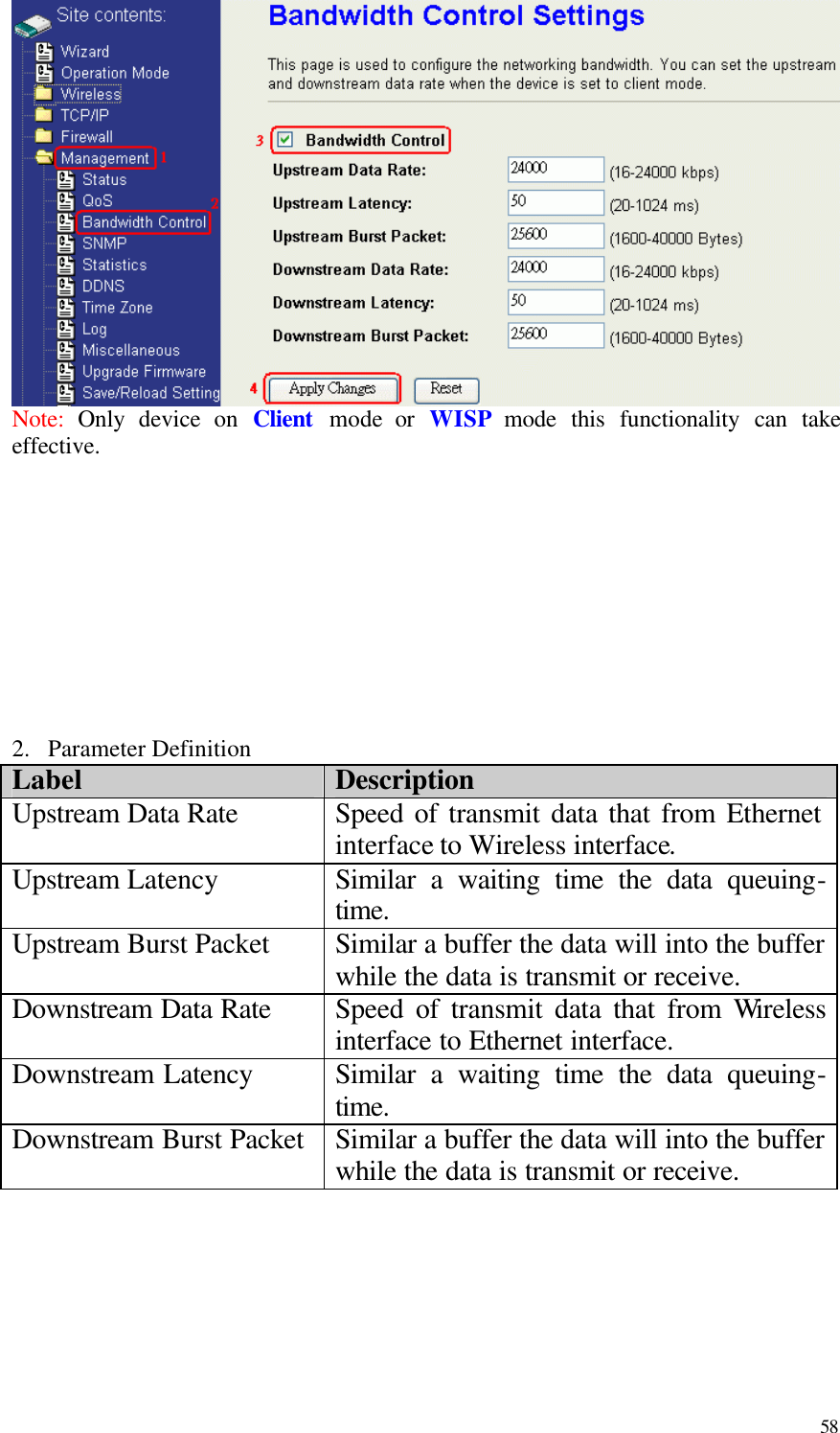
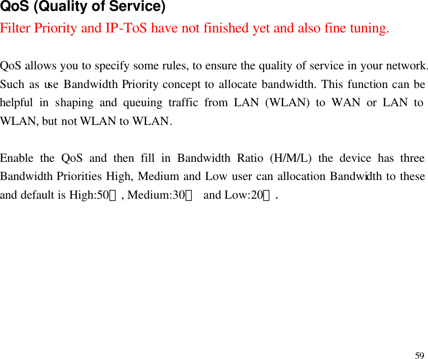
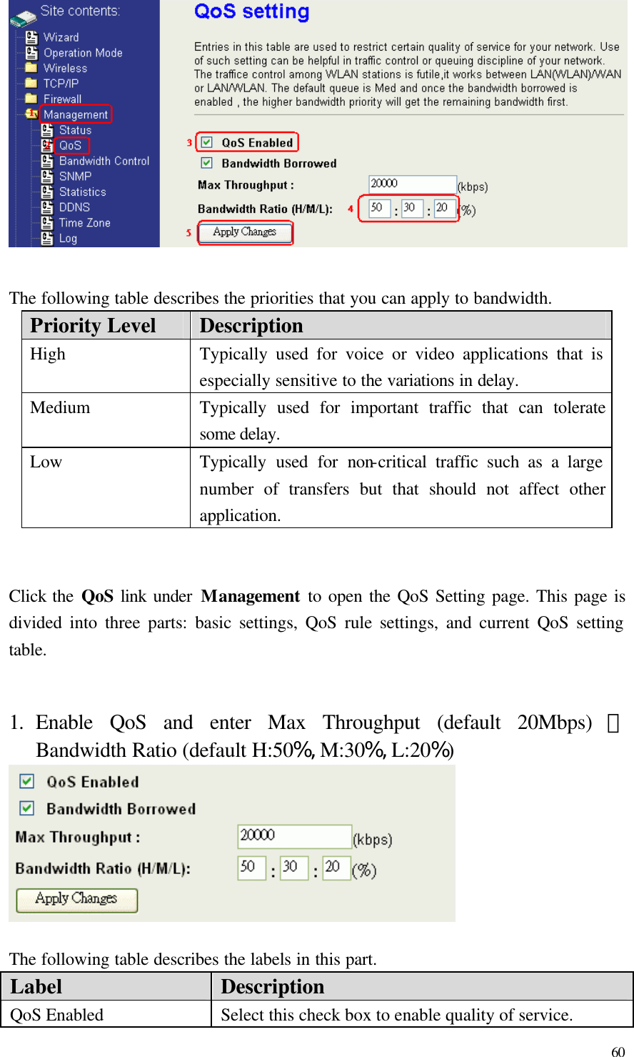
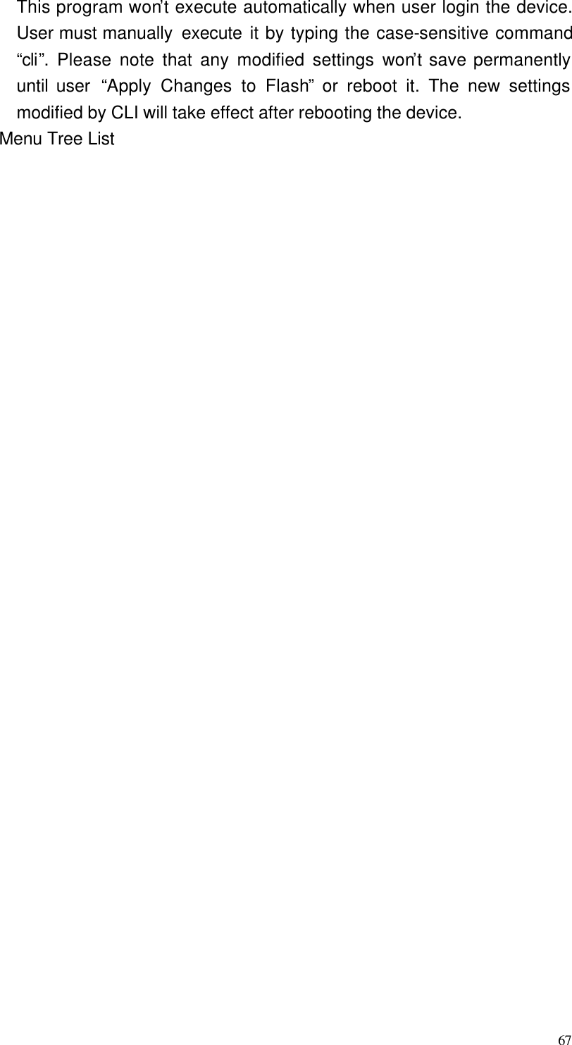
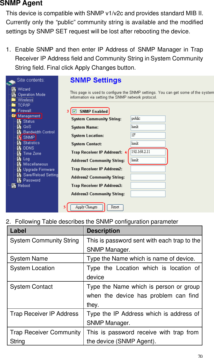
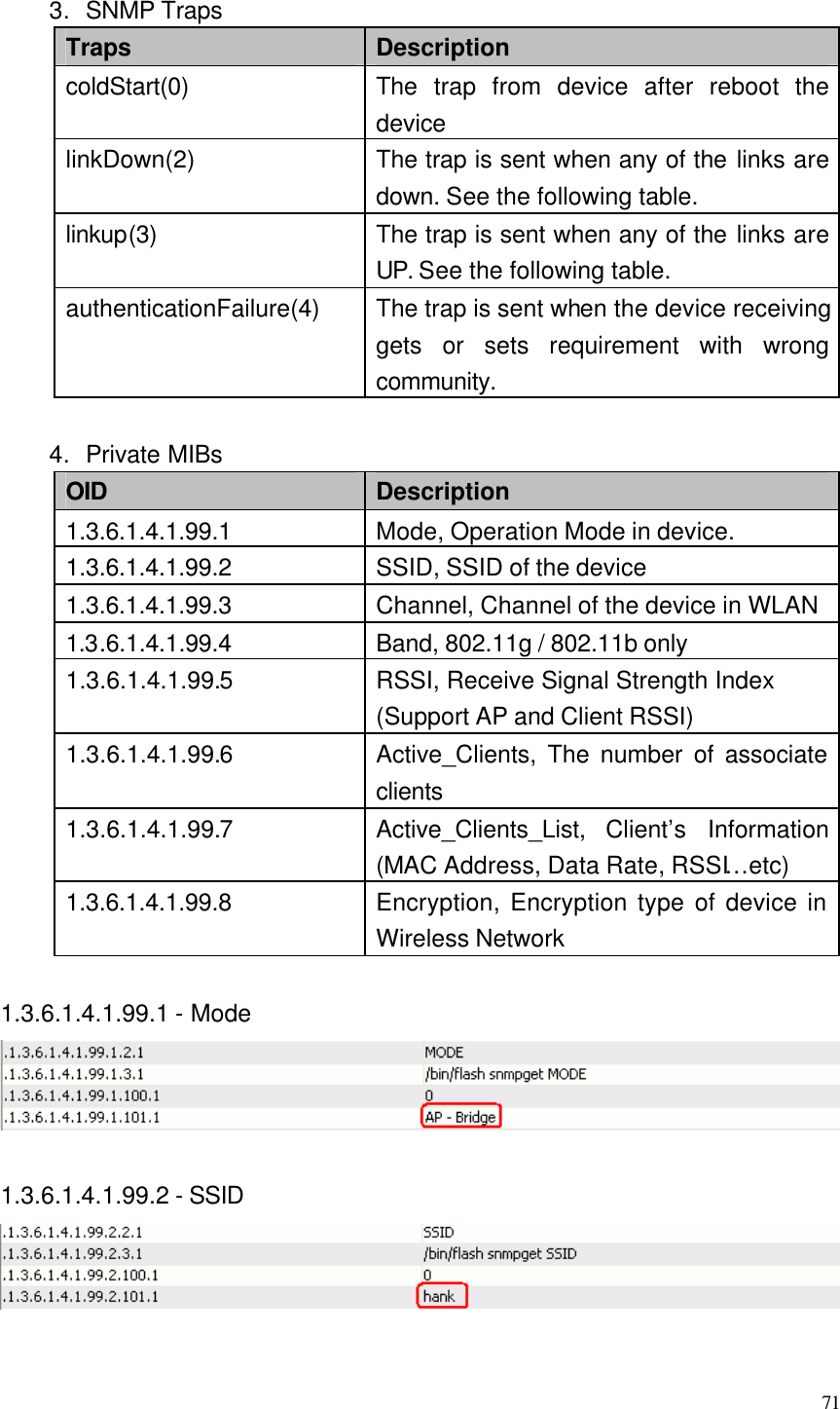
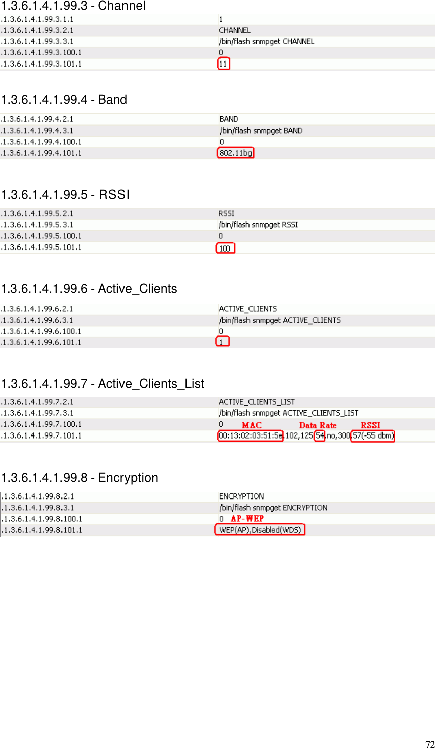
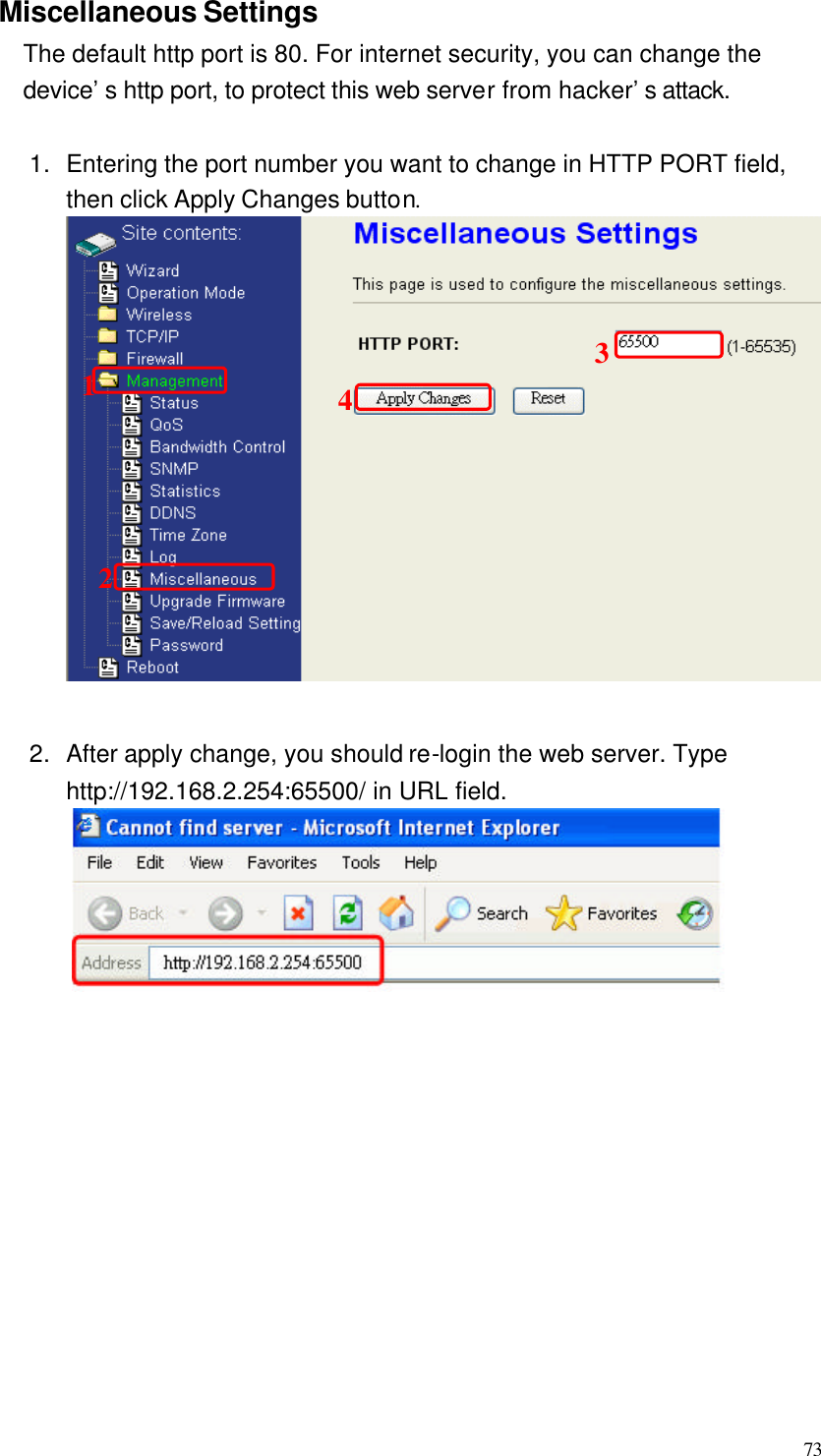
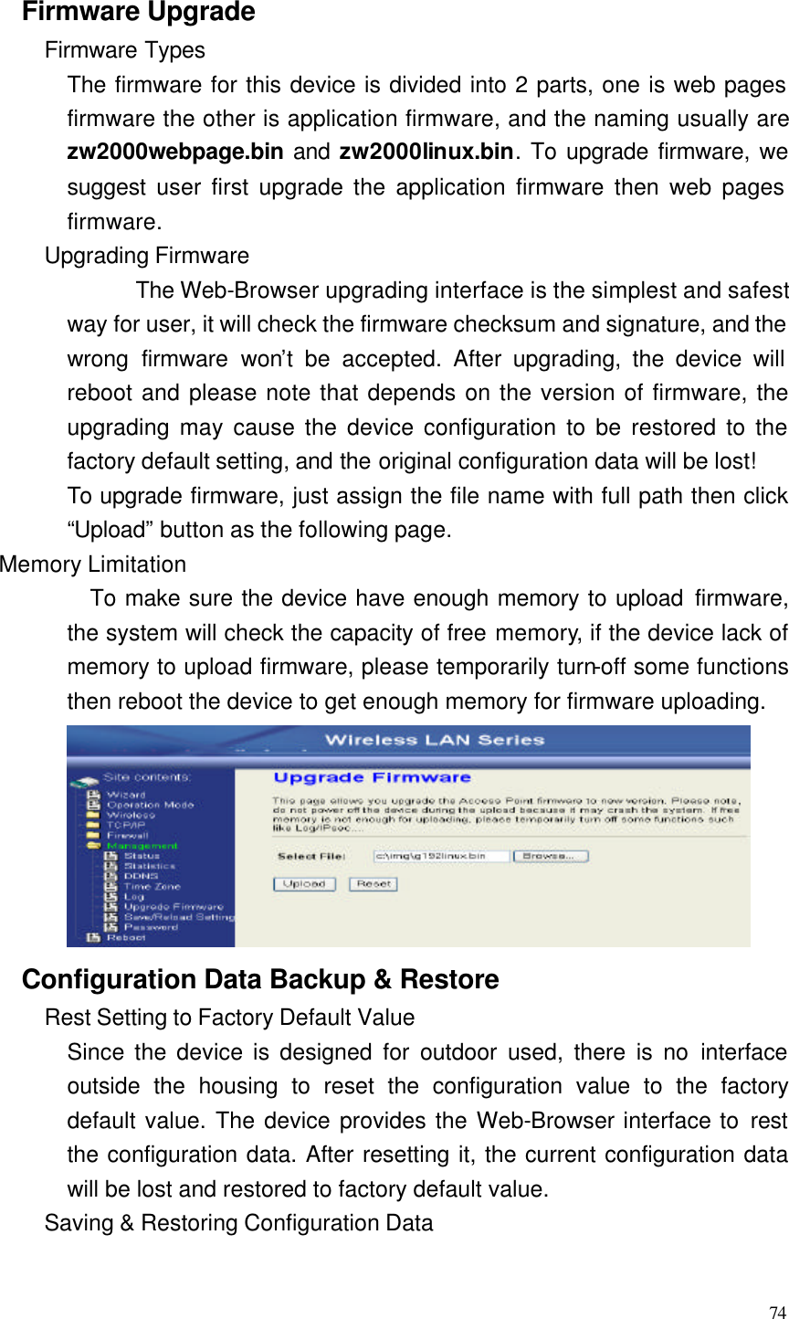
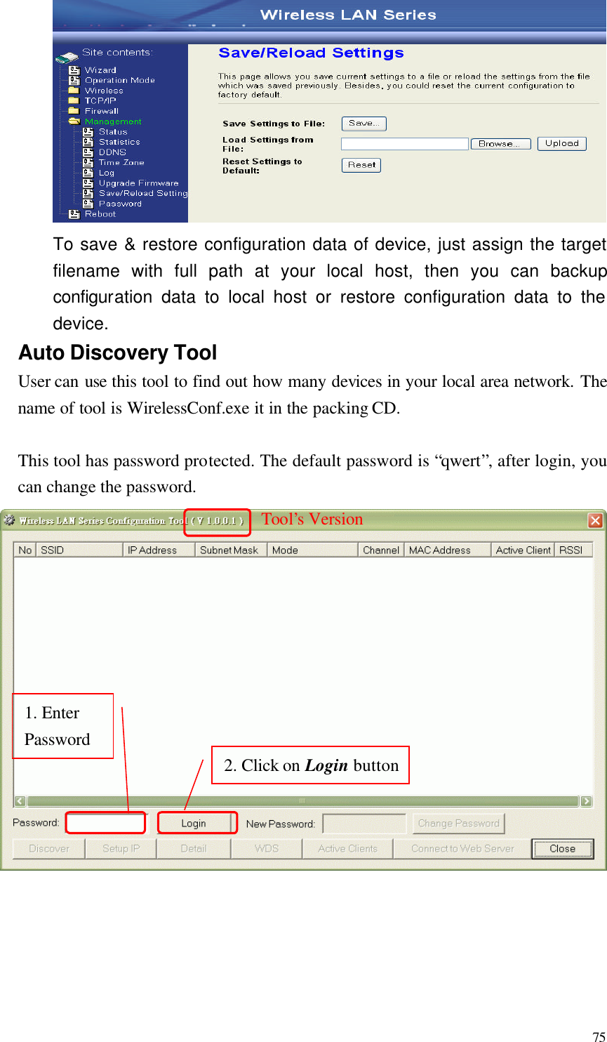
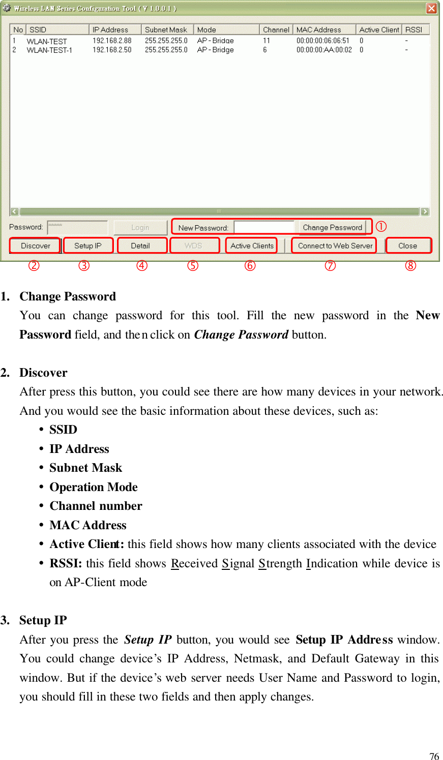
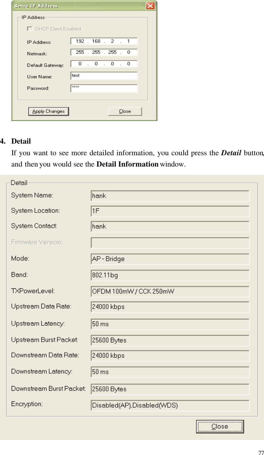
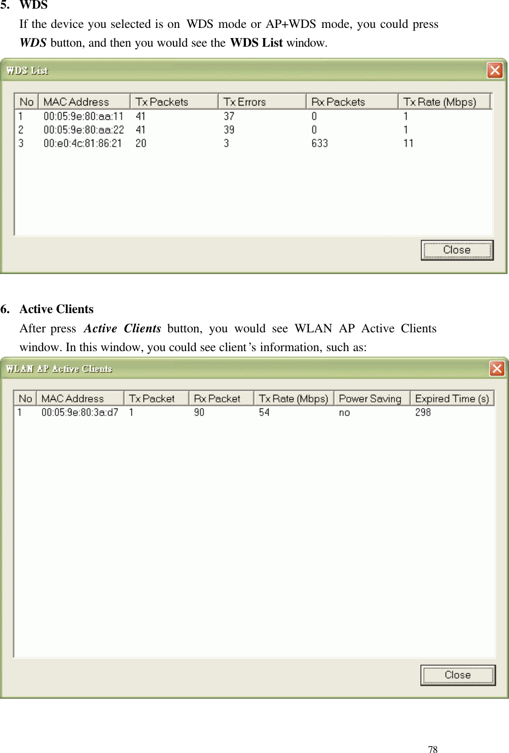
![68 A. Operation Mode B. Wireless Setting C. TCP/IP-LAN Setting D. TCP/IP-WAN Setting E. Route Setting F. Firewall Setting G. Management H. Apply Changes to Flash I. Reboot to take effect 0. Exit Wireless SettingA. Basic Settings B. Advanced Settings C. Security Settings D. Access Control Settings E. WDS Settings 0. Exit TCP/IP WAN Settings A. WAN Type B. IP Address C. Subnet Mask D. Default Gateway E. DNS1 F. DNS2 G. DNS3 Y. Clone MAC Address Z. uPNP 0. Exit Route Settings-[Dynamic Route]------------------ A. Dynamic Route B. RIP transmit to WAN C. RIP receive from WAN D. RIP transmit to LAN E. RIP receive from LAN -[Static Route]---------------------- - F. Static Route G. Add Static Route Setting H. Delete Static Route Setting I. Delete all Static Route Setting J. Current Static Route Setting List-[Route Table]------------------------ K. Show Route Table List 0. Exit Wireless Basic Settings A. Access Point Status B. QoS Settings C. Bandwidth Control D. SNMP Settings E. Password 0. Exit Firewall Settings A. Port Filtering B. IP Filtering C. MAC Filtering D. Port Forwarding E. DMZ 0. Exit Operation Mode 1: Router 2: Bridge 0: CancelTCP/IP-LAN SettingA. IP Address B. Subnet Mask C. Default Gateway D. DHCP E. DHCP Client Range F. 802.1d Spanning Tree G. Clone MAC Address H. MTU Size 0. Exit](https://usermanual.wiki/Zinwell/ZW-2000.Users-Manual-3/User-Guide-693877-Page-34.png)