Zinwell ZW-2200 802.11 a/g WLAN Outdoor AP User Manual ZW 2200 Manual 1220
Zinwell Corporation 802.11 a/g WLAN Outdoor AP ZW 2200 Manual 1220
Zinwell >
Contents
- 1. User Manual 1 of 2
- 2. User Manual 2 of 2
User Manual 1 of 2

Wireless LAN Device Series
WLAN Outdoor AP
ZW-2200-IA/OD User’s Manual
Version. 1.4.1 (2006.11.01)
1
TABLE OF CONTENTS
NOTICE ............................................................................................................................................................. 3
PREFACE.......................................................................................................................................................... 4
CH 1. ZW-2200 INSTALLATION ...................................................................................................................... 5
ZW-2200-IA................................................................................................................................................................... 5
Packing List............................................................................................................................................................... 5
Hardware Installation ............................................................................................................................................... 6
ZW-2200-OD ............................................................................................................................................................... 11
Packing List............................................................................................................................................................. 11
Hardware Installation ............................................................................................................................................. 12
CH 2. FIRST TIME CONFIGURATION ........................................................................................................... 17
BEFORE START TO CONFIGURE ..................................................................................................................................... 17
KNOWING THE NETWORK APPLICATION ....................................................................................................................... 18
CH 3. WLAN 1 WIRELESS CONFIGURATION.............................................................................................. 20
BASIC SETTINGS ........................................................................................................................................................... 20
ADVANCED SETTINGS ................................................................................................................................................... 23
CONFIGURING WIRELESS SECURITY ............................................................................................................................. 26
CONNECTING PROFILE .................................................................................................................................................. 29
MAC CLONE FOR SINGLE ETHERNET CLIENT .............................................................................................................. 30
CONFIGURING UNIVERSAL REPEATER........................................................................................................................... 31
CONFIGURING AS WLAN CLIENT ADAPTER ................................................................................................................. 33
CH 4. WLAN 2 WIRELESS CONFIGURATION.............................................................................................. 36
BASIC SETTINGS ........................................................................................................................................................... 36
ADVANCED SETTINGS ................................................................................................................................................... 38
CONFIGURING WIRELESS SECURITY ............................................................................................................................. 41
CONNECTING PROFILE .................................................................................................................................................. 44
MAC CLONE FOR SINGLE ETHERNET CLIENT .............................................................................................................. 45
CONFIGURING AS WLAN CLIENT ADAPTER ................................................................................................................. 45
CH 5. CONFIGURING WDS ........................................................................................................................... 48
WDS NETWORK TOPOLOGY .......................................................................................................................................... 48
WDS APPLICATION....................................................................................................................................................... 51
CH 6. ADVANCED CONFIGURATIONS......................................................................................................... 52
CONFIGURING LAN TO WAN FIREWALL ...................................................................................................................... 52
PORT FILTERING............................................................................................................................................................ 53
IP FILTERING ................................................................................................................................................................ 54
2
MAC FILTERING........................................................................................................................................................... 55
NAT (NETWORK ADDRESS TRANSLATION)................................................................................................................... 56
CONFIGURING PORT FORWARDING (VIRTUAL SERVER)........................................................................................................ 56
MULTIPLE SERVERS BEHIND NAT EXAMPLE: ............................................................................................................... 57
CONFIGURING DMZ ..................................................................................................................................................... 57
CONFIGURING WAN INTERFACE................................................................................................................................... 58
STATIC IP ...................................................................................................................................................................... 59
DHCP CLIENT (DYNAMIC IP)....................................................................................................................................... 59
PPPOE.......................................................................................................................................................................... 60
PPTP ............................................................................................................................................................................ 61
CONFIGURING CLONE MAC ADDRESS ......................................................................................................................... 62
CONFIGURING DHCP SERVER ...................................................................................................................................... 64
BANDWIDTH CONTROL................................................................................................................................................. 65
QOS (QUALITY OF SERVICE)......................................................................................................................................... 66
STATIC ROUTE SETUP ................................................................................................................................................... 69
DYNAMIC ROUTE SETUP............................................................................................................................................... 70
VPN PASS-THROUGH .................................................................................................................................................... 71
USING CLI MENU......................................................................................................................................................... 71
THE SYSTEM MANAGEMENT ........................................................................................................................................ 72
SNMP AGENT............................................................................................................................................................... 73
MISCELLANEOUS SETTINGS .......................................................................................................................................... 76
PING WAT C H DOG.......................................................................................................................................................... 77
AIMING TOOL ............................................................................................................................................................... 78
FIRMWARE UPGRADE.................................................................................................................................................... 79
CONFIGURATION DATA BACKUP & RESTORE ................................................................................................................ 80
AUTO DISCOVERY TOOL ............................................................................................................................................... 80
3
Notice
Warning: Changes or modifications to this unit not expressly approved by the party
responsible for compliance could void the user authority to operate the equipment.
This device complies with Part 15 of the FCC Rules. Operation is subject to the following
two conditions: (1) This device may not cause harmful interference, and (2) this device
must accept any interference received, including interference that may cause undesired
operation.
The user’s manual or instruction manual for an intentional or unintentional radiator shall
caution the user that changes or modifications not expressly approved by the party
responsible for compliance could void the user’s authority to operate the equipment.
NOTE: This equipment has been tested and found to comply with the limits for a Class B
digital device, pursuant to Part 15 of the FCC Rules. These limits are designed to provide
reasonable protection against harmful interference in a residential installation. This
equipment generates uses and can radiate radio frequency energy and, if not installed and
used in accordance with the instructions, may cause harmful interference to radio
communications.
However, there is no guarantee that interference will not occur in a particular installation. If
this equipment does cause harmful interference to radio or television reception, which can
be determined by turning the equipment off and on, the user is encouraged to try to correct
the interference by one or more of the following measures:
Reorient or relocate the receiving antenna.
Increase the separation between the equipment and receiver.
Connect the equipment into an outlet on a circuit different from that to which the
receiver is needed.
Consult the dealer or an experienced radio/TV technician for help.
Changes or modifications not expressly approved by the party responsible for compliance
could void the user‘s authority to operate the equipment.
The antenna(s) used for this transmitter must not be co-located or operating in conjunction
with any other antenna or transmitter.
Shielded interface cables must be used in order to comply with emission limits.

4
CAUTION:
1. The antenna(s) used for this transmitter must be fixed-mounted on outdoor permanent
structures with a separation distance of at least 2 meters from all persons and must not
be co-located or operating in conjunction with any other antenna or transmitter. Users
and installers must be provided with antenna installation instructions and transmitter
operating conditions for satisfying RF exposure compliance.
2. This Transmitter must not be co-located or operating in conjunction with any other
antenna or transmitter.
3. This equipment is only allowed to be professionally installed.
Preface
This guide is for the networking professional who installs and manages the Zinwell
5
ZW-2200-IA/OD product hereafter referred to as the “device”. To use this guide, you should
have experience working with the TCP/IP configuration and be familiar with the concepts
and terminology of wireless local area networks.
Ch 1. ZW-2200 Installation
ZW-2200-IA
Packing List
Before you start to install the IA, make sure the package contains the following items:

6
● Wireless IA AP unit * 1
● Mounting Kit * 1
● Power Over Ethernet Kit * 1
● Ground Wire * 1
● 2.5” U bolts * 2
● Waterproof Connector * 1
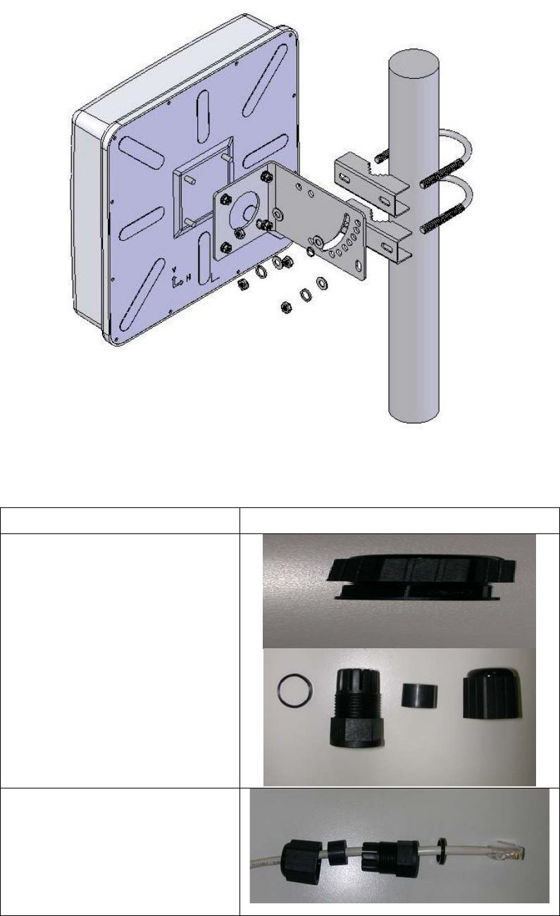
Hardware Installation
Once you check off everything from the package, you can start to install the IA. You can
mount to a pipe. The steps are showed in the following:
1. You must mount the IA into the bracket first.
2. You can use the 2.5 inches U bolt to mount on the pipe. The two U bolts must be mounted
tightly. Be aware of not over-tighten the U bolt.
7
3. After checking the IA is mounted well, you can connect the RJ-45 network cable to
Ethernet port of IA. The steps are showing as below:
Steps Pictures
1. Separate the waterproof
connector into four parts.
2. Put these parts of
waterproof connector on
the RJ-45 network cable.
12
3
4
4 3 2 1
IA Mounting Picture
8
3. Connect the RJ-45 network
cable to Ethernet port of
IA. And then install those
parts of waterproof
connector one by one.
Caution: The diameter of network cable has to be round; otherwise the waterproof
connector can’t fasten down it.
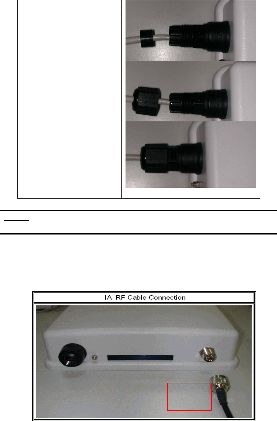
Additional waterproof tool, such as waterproof tape, is recommended to use to enhance
the waterproof function. It is suggested to have a lightening protector between antenna
and antenna port. Connect the RF cable as the figure of “IA RF Cable Connection” and
connect the ground wire as the figure of “IA Ground Wire Connection.”
3 2 1 A
4 3 2 1 B
C
2.4 G
Antenna
9
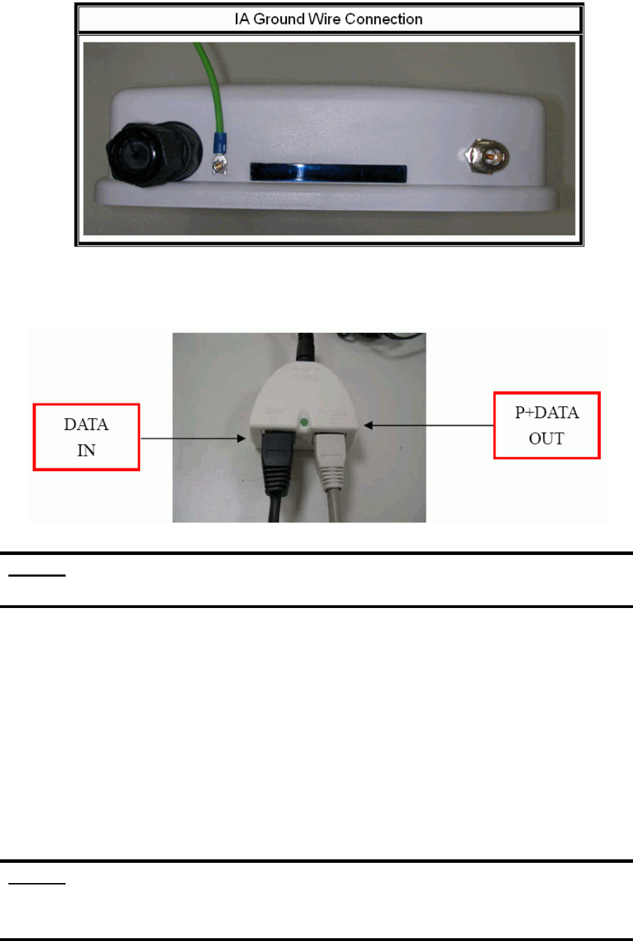
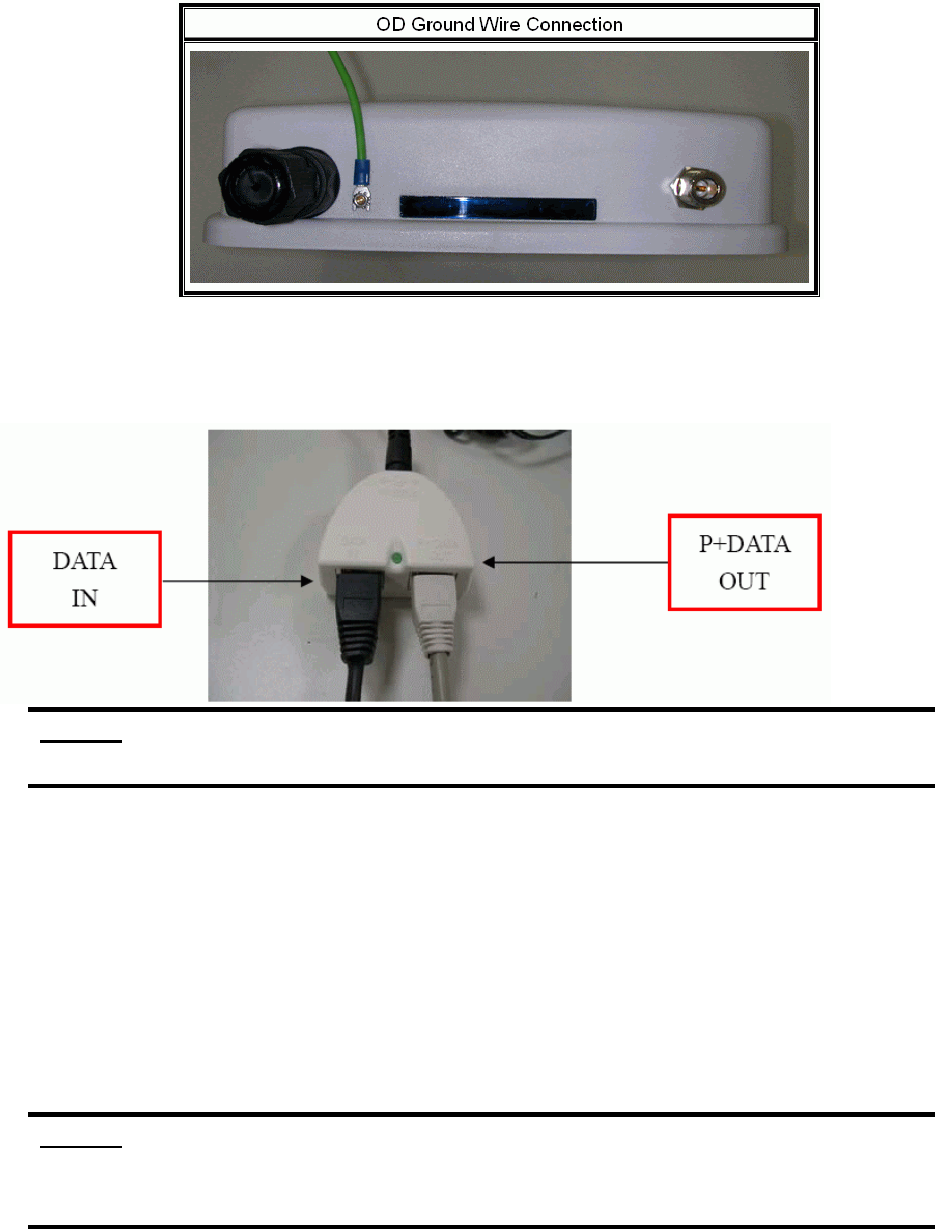
4. Plug the other end of the RJ-45 network cable to “P+ DATA OUT” port of PoE device.
The PoE device is guaranteed only in indoor environment.
Caution: DON’T plug the power cord into PoE device before you finish install the
antenna and Ground wire to ensure the safety.
Make sure the maximum length of the RJ-45 cable is shorter than 100M (about 109 yards)
for normal operation under IEEE 802.3 standards.
When you plug the regular RJ-45 cable into the PoE device, you should use the regular
RJ-45 cable to plug into the “DATA IN” of “Power Over Ethernet Kit” to connect to
hub/switch or use the crosslink RJ-45 cable (Not included in the Packing List) to connect
with user’s PC.
The RJ-45 network cable must be connected to the “P+DATA OUT” port.
Caution: Be careful! Don’t plug the two cables inversely. It will damage the devices!
And you have to use our PoE (included in the packing list) to guarantee that
power supply is normal.
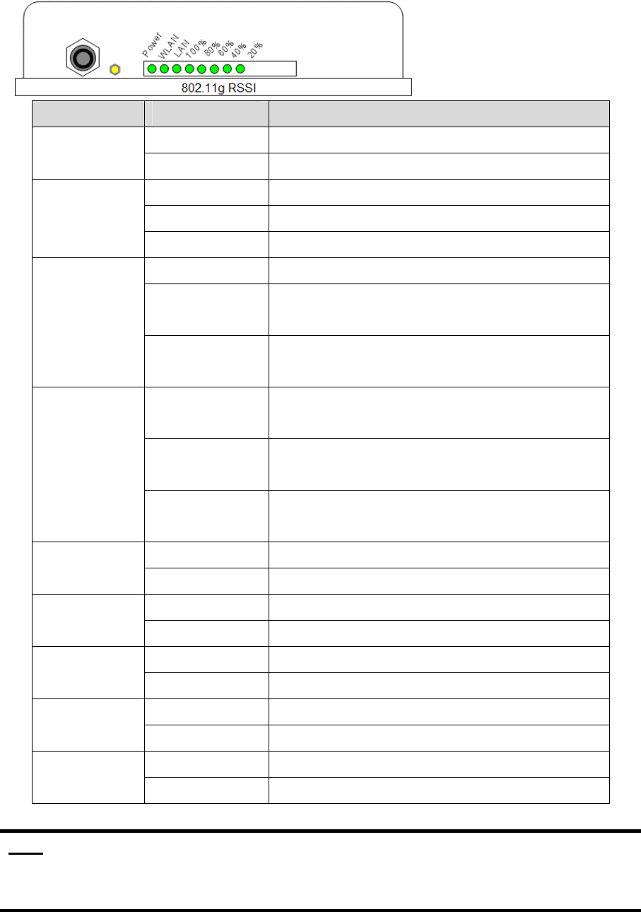
LED Panel
10
LED State Description
Off No Power
Power On System ready
Off No Power
On Wireless system ready
WLAN
Flashing Transmitting data through WLAN
Off No Power or connection
On Has physical connection to a Fast Ethernet
(100 Mbps) network
LAN
Flashing Transmitting or receiving data thru Ethernet
wire
All On Reset button triggered to Reboot this
device
All Flashing
very quickly
Reset button triggered over 5 seconds to
Reset to the default setting
RSSI
20%~100%
All Flashing
(slower)
In AP Client mode and scanning Wireless
signal
Off Wireless signal strength is 0%
RSSI 20% On Wireless signal strength is more than 0%
Off Wireless signal strength less than 21%
RSSI 40% On Wireless signal strength is more than 20%
Off Wireless signal strength less than 41%
RSSI 60% On Wireless signal strength is more than 40%
Off Wireless signal strength less than 61%
RSSI 80% On Wireless signal strength is more than 60%
Off Wireless signal strength less than 81%
RSSI 100% On Wireless signal strength is more than 80%
Note: While using Aiming Tool, the device will utilize the flashing frequency to
display the signal strength. About the detail, please refer to Ch4. Advanced
Configuration – Aiming tool.
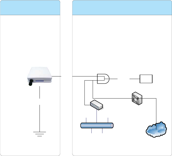
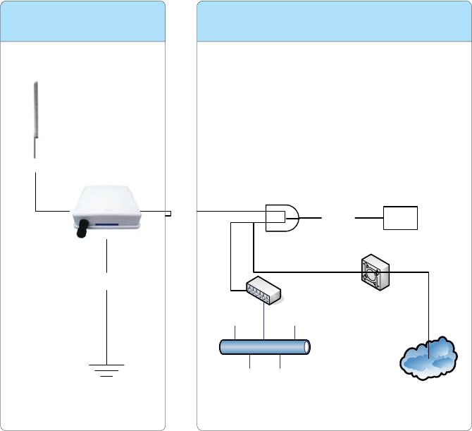
We recommend you refer to the following illustration as a guideline for hardware
installation.
11
ZW-2200-OD
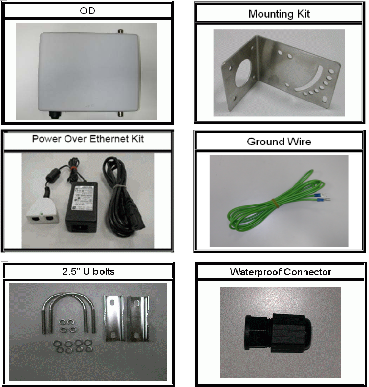
Packing List
Before you start to install the OD, make sure the package contains the following items:
● Wireless OD AP unit * 1
● Mounting Kit * 1
● Power Over Ethernet Kit * 1
● Ground Wire * 1
● 2.5” U bolts * 2
Internet
Ethernet
HUB/SWITCH
ADSL
Ground
Outdoor Indoor
Power
Injector
Power
Supply
RJ-45 48V in
12
● Waterproof Connector * 1
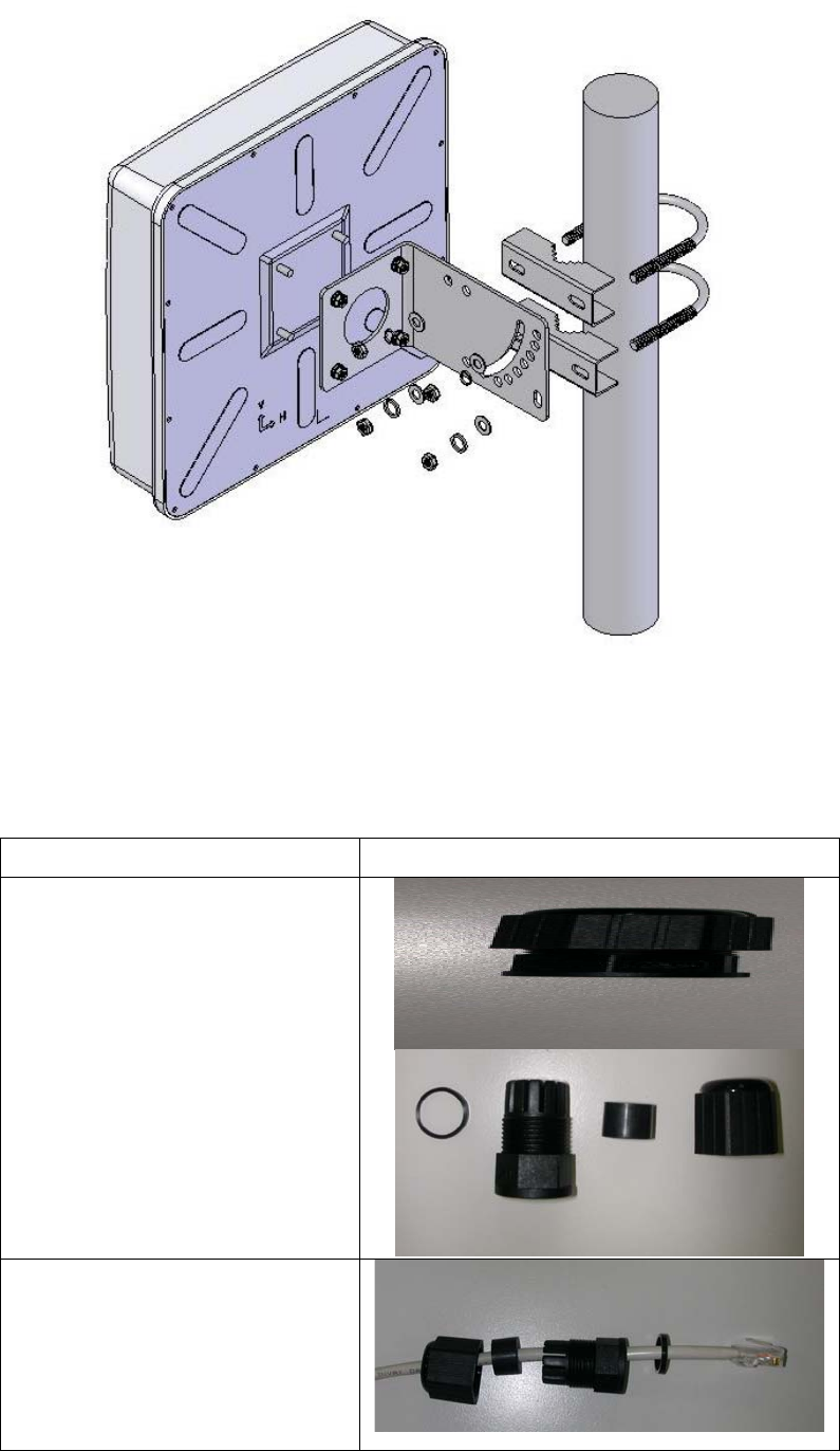
Hardware Installation
Once you check off everything from the package, you can start to install the OD. You can
mount to a pipe, a pole or to the side of a building. The steps are showed in the following:
1. You must mount the OD into the bracket first.
2. You can use the 2.5 inches U bolt to mount on the pipe. The two U bolts must be
mounted tightly. Be aware of not over-tighten the U bolt.
13
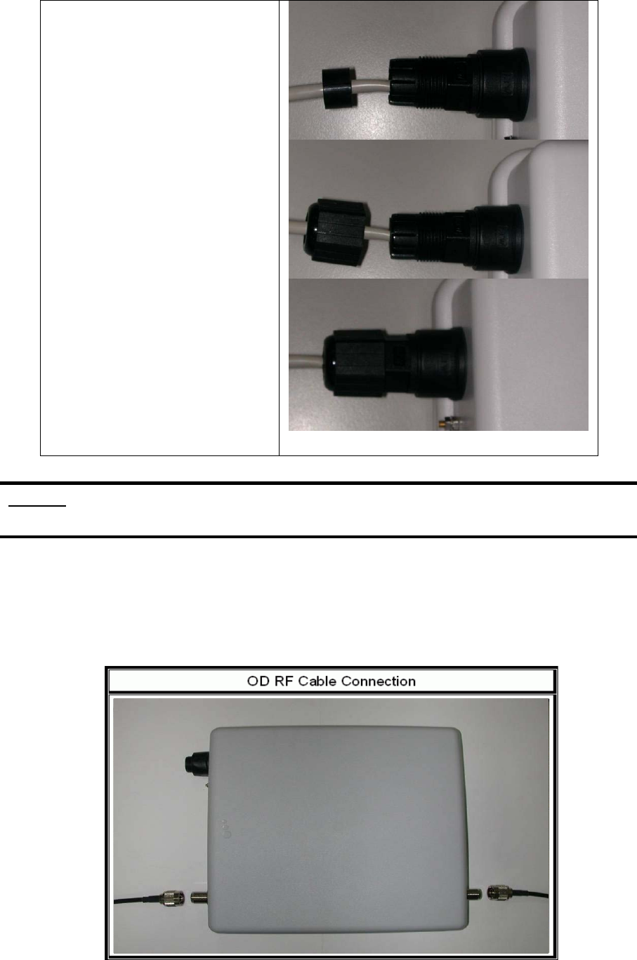
3. After checking the OD is mounted well, you can connect the following two cables: the
RJ-45 network cable to Ethernet port of OD and the RF cable to antenna port. The
RJ-45 network connects steps are showing as below:
Steps Pictures
1. Separate the waterproof
connector into four parts.
2. Put these parts of
waterproof connector on
the RJ-45 network cable.
OD Mounting Picture
12
3
4
4 3 2 1
14
3. Connect the RJ-45 network
cable to Ethernet port of
IA. And then install those
parts of waterproof
connector one by one.
Caution: The diameter of network cable has to be round; otherwise the waterproof
connector can’t fasten down it.
Additional waterproof tool, such as waterproof tape, is recommended to use to enhance
the waterproof function. It is suggested to have a lightening protector between antenna
and antenna port. Connect the RF cable as the figure of “OD RF Cable Connection” and
connect the ground wire as the figure of “OD Ground Wire Connection.”
3 2 1 A
4 3 2 1 B
C
2.4G
A
ntenna
5G
Antenna
15
4. Plug the other end of the waterproof RJ-45 cable to the PoE device.
The PoE device is guaranteed only in indoor environment.
Caution: DON’T plug the power cord into PoE device before you finish install the
antenna and Ground wire to ensure the safety.
Make sure the maximum length of the RJ-45 cable is shorter than 100M (about 109 yards)
for normal operation under IEEE 802.3 standards.
When you plug the regular RJ-45 cable into the PoE device, you should use the regular
RJ-45 cable to plug into the “DATA IN” of “Power Over Ethernet Kit” to connect to
hub/switch or use the crosslink RJ-45 cable (Not included in the Packing List) to connect
with user’s PC.
The RJ-45 network cable must be connected to the “P+DATA OUT” port.
Caution: Be careful! Don’t plug the two cables inversely. It will damage the devices!
And you have to use our PoE (included in the packing list) to guarantee that
power supply is normal.
LED Panel

16
LED State Description
Off No Power
Power On System ready
Off No Power
On Wireless system ready
WLAN
Flashing Transmitting data through WLAN
Off No Power or connection
On Has physical connection to a Fast Ethernet
(100 Mbps) network
LAN
Flashing Transmitting or receiving data thru Ethernet
wire
All On Reset button triggered to Reboot this
device
All Flashing
quickly
Reset button triggered over 5 seconds to
Reset to the default setting
RSSI
20%~100%
All Flashing
(slower)
In AP Client mode and scanning Wireless
signal
Off Wireless signal strength is 0%
RSSI 20% On Wireless signal strength is more than 0%
Off Wireless signal strength less than 21%
RSSI 40% On Wireless signal strength is more than 20%
Off Wireless signal strength less than 41%
RSSI 60% On Wireless signal strength is more than 40%
Off Wireless signal strength less than 61%
RSSI 80% On Wireless signal strength is more than 60%
Off Wireless signal strength less than 81%
RSSI 100% On Wireless signal strength is more than 80%
Note: While using Aiming Tool, the device will utilize the flashing frequency to
display the signal strength. About the detail, please refer to Ch4. Advanced
Configuration – Aiming tool.
We recommend you refer to the following illustration as a guideline for hardware
installation.
17
Ch 2. First Time Configuration
Before Start to Configure
There are two ways to configure the device, one is through web-browser, and the other is
through Secure Shell CLI interface. To access the configuration interfaces, make sure
you are using a computer connected to the same network as the device. The default IP
address of the device is 192.168.2.254, and the subnet-mask is 255.255.255.0.
The device has three operation modes (Router/Bridge/WISP). In bridge mode, also
known as AP Client, you can access the device by both WLAN (Wireless Local Area
Network) and wired LAN. And in router/WISP modes, the device can be accessed by
both WLAN and WAN. The default IP addresses for the device are 192.168.2.254(for
Internet
Ethernet
HUB/SWITCH
ADSL
Ground
Outdoor Indoor
Power
Injector
Power
Supply
RJ-45 48V in
Antenna
18
LAN), 172.1.1.1(for WAN), so you need to make sure the IP address of your PC is in the
same subnet as the device, such as 192.168.2.X (for LAN), 172.1.1.X (for WAN).
Please note that the DHCP server inside the device is default to up and running. Do not
have multiple DHCP servers in your network environment, otherwise it will cause
abnormal situation.
We also provide an auto-discovery tool which is for finding out the IP of the device. In
case, you’ve forgot the IP of the device or the IP of the device has been changed, you
can use the tool to find out the IP of the device even your PC is not in the same subnet as
the device is.
Knowing the Network Application
The device can act as the following roles, and it supports WDS (Wireless Distribution
System) function.
Access Point
WDS (Wireless Repeater)
Bridge/Router
WISP
AP Client
The device provides 3 different operation modes and the wireless radio of device can act
as AP/Client/WDS. The operation mode is about the communication mechanism
between the wired Ethernet NIC and wireless NIC, the following is the types of operation
mode.
Router
The wired Ethernet (WAN) port is used to connect with ADSL/Cable modem and the
wireless NIC is used for your private WLAN. The NAT is existed between the 2 NIC and
all the wireless clients share the same public IP address through the WAN port to ISP.
The default IP configuration for WAN port is static IP. You can access the web server of
device through the default WAN IP address 172.1.1.1 and modify the setting base on
your ISP requirement.
Bridge
The wired Ethernet and wireless NIC are bridged together. Once the mode is selected, all
the WAN related functions will be disabled.
WISP (Wireless ISP)
This mode can let you access the AP of your wireless ISP and share the same public IP
address from your ISP to the PCs connecting with the wired Ethernet port of the device.

19
To use this mode, first you must set the wireless radio to be client mode and connect to
the AP of your ISP then you can configure the WAN IP configuration to meet your ISP
requirement.
The wireless radio of the device acts as the following roles.
AP (Access Point)
The wireless radio of device serves as communications “hub” for wireless clients and
provides a connection to a wired LAN.
AP Client
This mode provides the capability to connect with the other AP using
infrastructure/Ad-hoc networking types. With bridge operation mode, you can directly
connect the wired Ethernet port to your PC and the device becomes a wireless adapter.
And with WISP operation mode, you can connect the wired Ethernet port to a hub/switch
and all the PCs connecting with hub/switch can share the same public IP address from
your ISP.
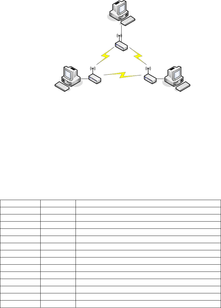
WDS (Wireless Distribution System)
This mode serves as a wireless repeater; the device forwards the packets to another AP
with WDS function. When this mode is selected, all the wireless clients can’t survey and
connect to the device. The device only allows the WDS connection.
WDS+AP
This mode combines WDS plus AP modes, it not only allows WDS connections but also
the wireless clients can survey and connect to the device.
The following table shows the supporting combination of operation and wireless radio
modes.
Bridge Router WISP
AP V V X
WDS V V X
Client V X V
AP+WDS V V X
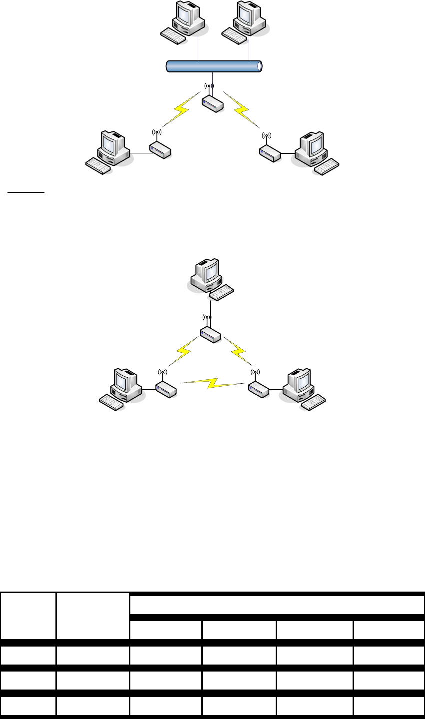
Hereafter are some topologies of network application for your reference.
20
Bridge Mode
With
AP
Bridge Mode
With
WDS + AP
Bridge Mode
Router Mode
With
WDS + AP
WISP Mode
Internet
Broadband
Modem
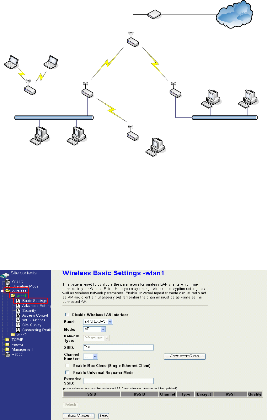
Ch 3. WLAN 1 Wireless Configuration
Basic Settings
Disable Wireless LAN Interface
21
Disable the wireless interface of device
Band:
The device supports 2.4GHz(B), 2.4GHz(G) and 2.4GHz(B+G) mixed modes.
Mode:
The radio of device supports different modes as following:
1. AP
The radio of device acts as an Access Point to serves all wireless clients to join a
wireless local network.
2. Client
Support Infrastructure and Ad-hoc network types to act as a wireless adapter.
3. WDS
Wireless Distribution System, this mode serves as a wireless repeater, only devices
with WDS function supported can connect to it, all the wireless clients can’t survey and
connect the device when the mode is selected.
4. AP+WDS
Support both AP and WDS functions, the wireless clients and devices with WDS
function supported can survey and connect to it.
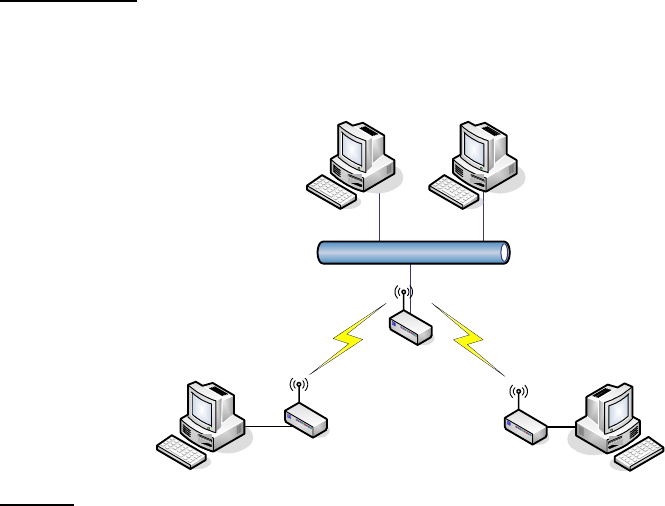
Network Type:
Infrastructure:
This type requires the presence of 802.11b/g Access Point. All communication is done via the
Access Point.
Ethernet
AP
AP Client #2
AP Client #1
Ad Hoc:
This type provides a peer-to-peer communication between wireless stations. All the
communication is done from Client to Client without any Access Point involved. Ad Hoc networking
must use the same SSID and channel for establishing the wireless connection.
22
PC #3 PC #2
AP Client #1
AP Client #2AP Client #3
PC #1
In client mode, the device can’t support the Router mode function including Firewall
and WAN settings.
SSID:
The SSID is a unique identifier that wireless networking devices use to establish and
maintain wireless connectivity. Multiple access point/bridges on a network or sub-network
can use the same SSID. SSIDs are case sensitive and can contain up to 32 alphanumeric
characters. Do not include spaces in your SSID.
Channel Number:
The following table is the available frequencies (in MHz) for the 2.4-GHz radio:
Channel No. Frequency Country Domain
1 2412 Americas, EMEA, Japan, and China
2 2417 Americas, EMEA, Japan, and China
3 2422 Americas, EMEA, Japan, Israel, and China
4 2427 Americas, EMEA, Japan, Israel, and China
5 2432 Americas, EMEA, Japan, Israel, and China
6 2437 Americas, EMEA, Japan, Israel, and China
7 2442 Americas, EMEA, Japan, Israel, and China
8 2447 Americas, EMEA, Japan, Israel, and China
9 2452 Americas, EMEA, Japan, Israel, and China
10 2457 Americas, EMEA, Japan, and China
11 2462 Americas, EMEA, Japan, and China
12 2467 EMEA and Japan
13 2472 EMEA and Japan
14 2484 Japan only
※ EMEA (Europe, the Middle East and Africa).
When set to “Auto”, the device will find the least-congested channel for use.
Associated Client:
Show the information of active wireless client stations that connected to the device.
REMARK
IEEE 802.11b or 802.11g operation of this product in the U.S.A. is firmware-limited to channels 1 through 11.

23
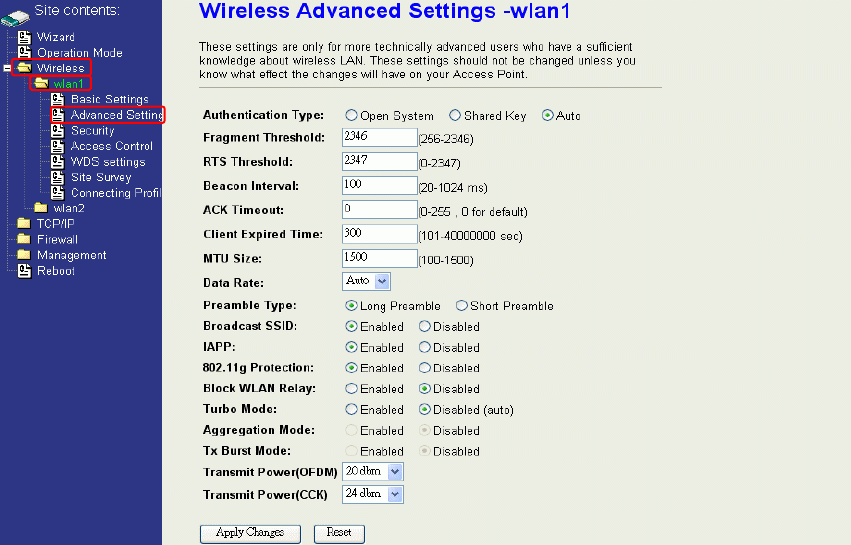
Advanced Settings
These settings are only for more technically advanced users who have sufficient
knowledge about wireless LAN. These settings should not be changed unless you
know what effect the changes will have on your device. The default setting is optimized
for the normal operation. For specific application, setting configuration will required
highly attention to reach optimistic condition.
Note:
Any unreasonable value change to default setting will reduce the
throughput of the device.
24
Authentication Type
The device supports two Authentication Types “Open system” and “Shared Key”. When you
select “Share Key”, you need to setup “WEP” key in “Security” page (See the next section).
The default setting is “Auto”. The wireless client can associate with the device by using one
of the two types.
Fragment Threshold
The fragmentation threshold determines the size at which packets are fragmented (sent as
several pieces instead of as one block). Use a low setting in areas where communication is
poor or where there is a great deal of radio interference. This function will help you to
improve the network performance.
RTS Threshold
The RTS threshold determines the packet size at which the radio issues a request to send
(RTS) before sending the packet. A low RTS Threshold setting can be useful in areas where
many client devices are associating with the device, or in areas where the clients are far
apart and can detect only the device and not each other. You can enter a setting ranging
from 0 to 2347 bytes.
Beacon Interval
The beacon interval is the amount of time between access point beacons in mini-seconds.
The default beacon interval is 100.
ACK Timeout
The default ACK timeout is 0. You may need to change this value due to the environment or
distance.
Client Expired Time
25
The client expired time determines time interval the client need to re-associate with the
device while client is idle. The default client expired time is 300 sec.
MTU Size
Maximum Transmission Unit, the default MTU size is 1500. The MTU setting controls the
maximum Ethernet packet size your PC will send. Why a limit? Because although larger
packets can be constructed and sent, your ISP and Internet backbone routers and
equipment will fragment any larger than their limit, then these parts are re-assembled by the
target equipment before reading. This fragmentation and re-assembly is not optimal. You
may need to change the MTU for optimal performance of your wireless LAN traffic.
Data Rate
The standard IEEE 802.11b/11g supports 1, 2, 5.5, 11 / 6, 9, 12, 18, 24, 36, 48 and 54 Mbps
data rates. You can choose the rate that the device uses for data transmission. The default
value is “auto”. The device will use the highest possible selected transmission rate.
Preamble Type
The preamble is part of the 802.11 frame and is PHY dependant. All 802.11b/g systems
support the long preamble. The short preamble (optional) maybe used to improve
throughput when all stations on the network support the short preamble.
Broadcast SSID
Broadcasting the SSID will let your wireless clients find the device automatically. If you are
building a public Wireless Network, disable this function can provide better security. Every
wireless stations located within the coverage of the device must connect this device by
manually configure the SSID in your client settings.
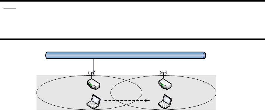
IAPP (Inter-Access Point Protocol)
This function will let Wireless Stations roam among a network environment with multiple
devices. Wireless Stations are able to switch from one device to another as they move
between the coverage areas. Users can have more wireless working range. An example is
as the following figure.
You should comply with the following instructions to roam among the wireless coverage
areas.
Note: For implementing the roaming function, the setting MUST comply the following two
items.
All the devices must be in the same subnet network and the SSID must be the same.
If you use the 802.1x authentication, you need to have the user profile in these devices
for the roaming station.
Ethernet
Wireless Station moves
between the coverage areas
DEV 1 DEV 2
802.11g Protection
26
This ensures that 802.11g stations are backwards compatible with legacy 802.11b
stations. With 802.11g protection enabled, a CTS will be used to lock out 802.11b stations
while the 802.11g station is transmitting. While this does allow backwards compatibility with
legacy 802.11b stations, it should be disabled in a pure 802.11g environment, as it will have
a significant impact on 802.11g performance (as high as 50% decrease in throughput).
Block WLAN Relay (Isolate Client)
The device supports isolation function. If you are building a public Wireless Network, enable
this function can provide better security. The device will block packets between wireless
clients (relay). All the wireless clients connected to the device can’t see each other.
Aggregation Mode
Not applicable for WLAN 1.
Tx Burst Mode
Not applicable for WLAN 1.
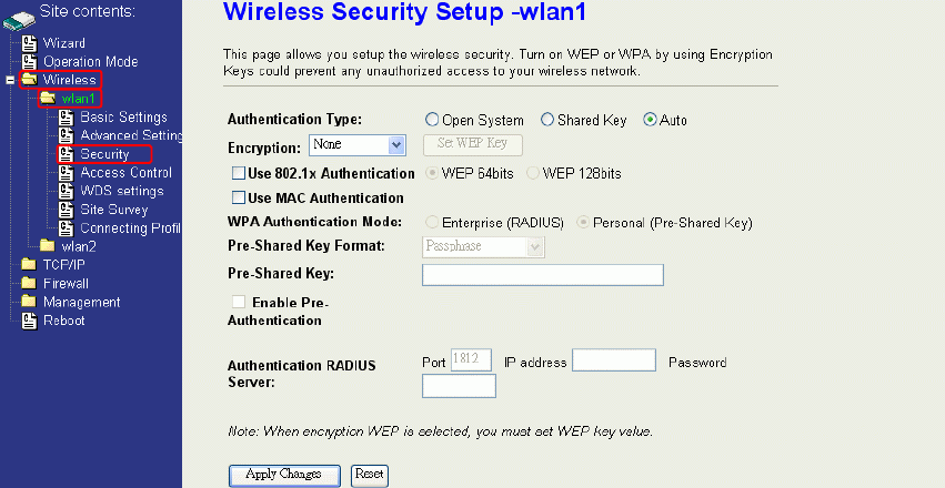
Configuring Wireless Security
This device provides complete wireless security function include WEP, 802.1x, WPA-TKIP,
WPA2-AES and WPA2-Mixed in different mode (see the Security Support Table).
The default security setting of the encryption function is disabled. Choose your preferred
security setting depending on what security function you need.
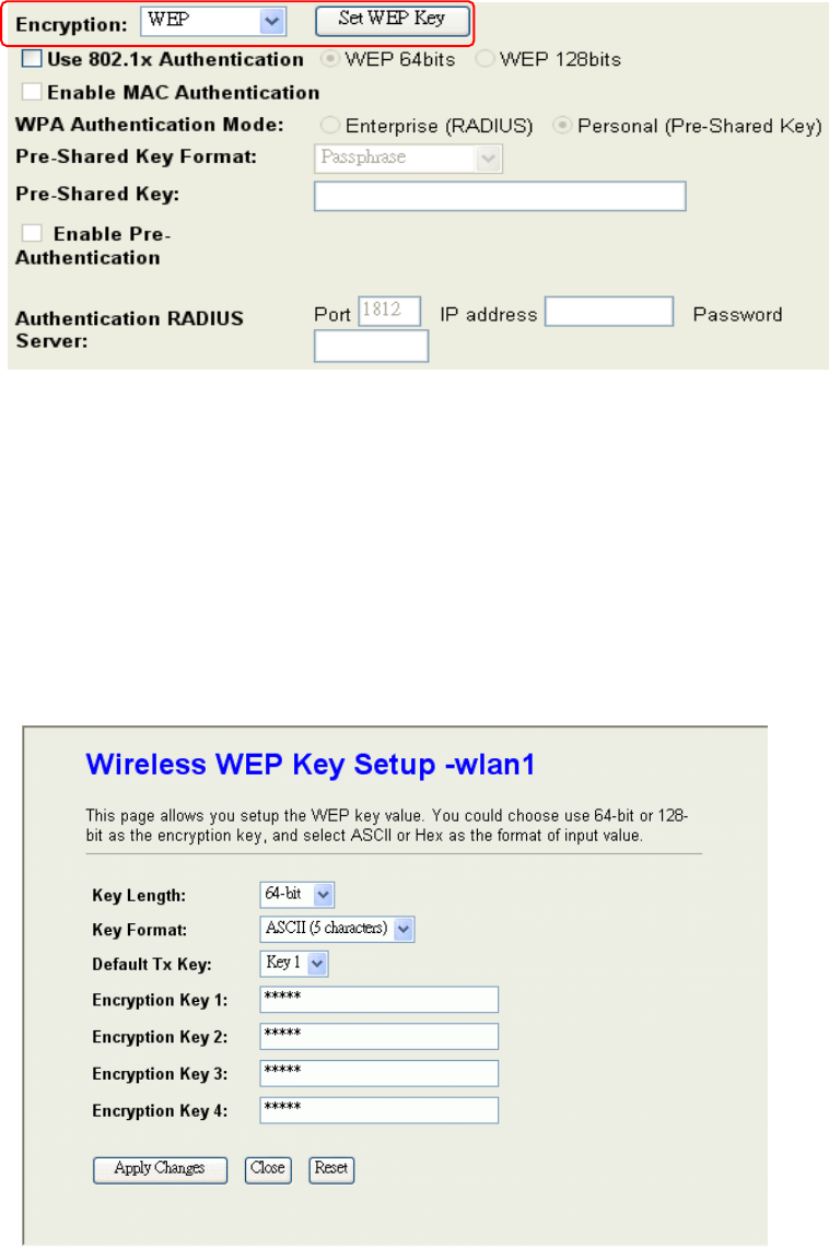
WEP Encryption Setting
Wired Equivalent Privacy (WEP) is implemented in this device to prevent unauthorized
access to your wireless network. The WEP setting must be as same as each client in your
wireless network. For more secure data transmission, you can change encryption type to
“WEP” and click the “Set WEP Key” button to open the “Wireless WEP Key setup”
page.
27
When you decide to use the WEP encryption to secure your WLAN, please refer to the
following setting of the WEP encryption:
64-bit WEP Encryption:64-bit WEP keys are as same as the encryption method of
40-bit WEP. You can input 10 hexadecimal digits (0~9, a~f or A~F) or 5 ACSII chars.
128-bit WEP Encryption:128-bit WEP keys are as same as the encryption method of
104-bit WEP. You can input 26 hexadecimal digits (0~9, a~f or A~F) or 10 ACSII chars.
The Default Tx Key field decides which of the four keys you want to use in your WLAN
environment.
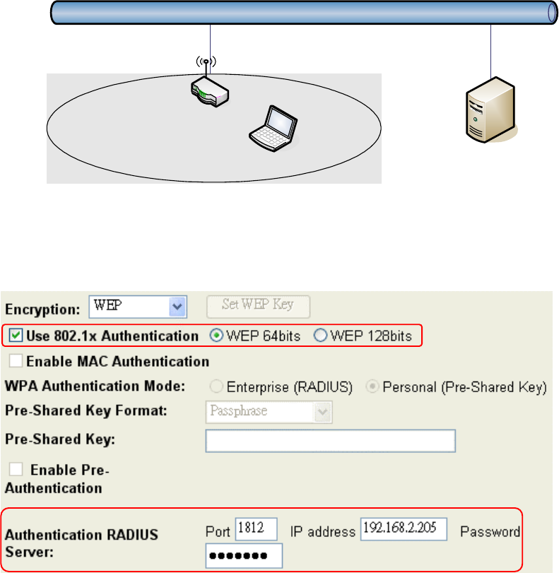
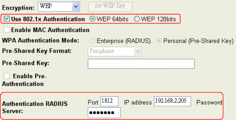
WEP Encryption with 802.1x Setting
The device supports external RADIUS Server that can secure networks against
unauthorized access. If you use the WEP encryption, you can also use the RADIUS server
to check the admission of the users. By this way every user must use a valid account before
accessing the Wireless LAN and requires a RADIUS or other authentication server on the
network. An example is shown as following.
28
Ethernet
RADIUS Server
Wireless Station
AP
You should choose WEP 64 or 128 bit encryption to fit with your network environment first.
Then add user accounts and the target device to the RADIUS server. In the device , you
need to specify the IP address、Password (Shared Secret) and Port number of the target
RADIUS server.
WPA Encryption Setting
WPA feature provides a high level of assurance for end-users and administrators that their
data will remain private and access to their network restricted to authorized users. You can
choose the WPA encryption and select the Authentication Mode.
WPA Authentication Mode
This device supports two WPA modes. For personal user, you can use the Pre-shared Key
to enhance your security setting. This mode requires only an access point and client station
that supports WPA-PSK. For Enterprise, authentication is achieved via WPA RADIUS Server.
You need a RADIUS or other authentication server on the network.
Enterprise (RADIUS):
When WPA Authentication mode is Enterprise (RADIUS), you have to add user accounts
and the target device to the RADIUS Server. In the device , you need to specify the IP
address、Password (Shared Secret) and Port number of the target RADIUS server.
Pre-Share Key:
This mode requires only an access point and client station that supports WPA-PSK. The
WPA-PSK settings include Key Format, Length and Value. They must be as same as
29
each wireless client in your wireless network. When Key format is Passphrase, the key
value should have 8~63 ACSII chars. When Key format is Hex, the key value should have
64 hexadecimal digits (0~9, a~f or A~F).
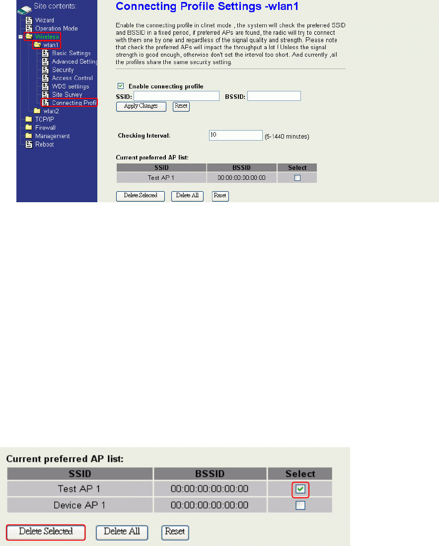
Connecting Profile
To enable this function, this device must be in the client mode. User clicks to enable
this function and input the SSID of preferred AP and then click “Apply Changes”. The
BSSID field is an option in case of two preferred APs having the same SSID. In this
case, this device will check both SSID and BSSID and connect to the matching AP. We
can leave it empty in the normal case.
After enabling the connecting profile, the system will check the preferred SSID in a
fixed period. If preferred APs are found, the radio will try to connect with them one by
one from top to down of the list and regardless of the signal quality and strength. The
users can put their most favorite AP on the top so it will be connected first. Please note
that check the preferred APs will impact the throughput a lot! Unless the signal strength
is good enough, otherwise don't set the interval too short. The default value is 10
minutes. And currently, all the profiles share the same security setting.
To delete one SSID in the list, users click the square to select it and click “Delete
Selected” and then click “OK” in the pop-up window to confirm it. The user can delete
30
the whole list once for all! Just click “Delete All” and then click “OK” in the pop-up
window to confirm it.
To simply disable this function, the user just clicks to disable “Enable connecting
profile”. The preferred AP list will be preserved for the next use.
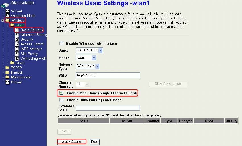
MAC Clone for Single Ethernet Client
Enable/Disable Mac Clone (Single Ethernet Client) in Wireless-Basic Settings page
determines whether the Ethernet Client use it’s own MAC address or AP-Client’s MAC
address to transmit data. Enable MAC Clone, the single Ethernet client can use its own
MAC address. Disable MAC Clone, the single Ethernet client must to use AP-Client’s
MAC address.
While you use this device act as AP-Client and only one host connect to this device via
Ethernet, you need to check this option in this page, otherwise the other device can’t
recognize your host behind AP-Client. If you use hub/switch connect multi-device to this
AP-Client, you should uncheck this option.
31
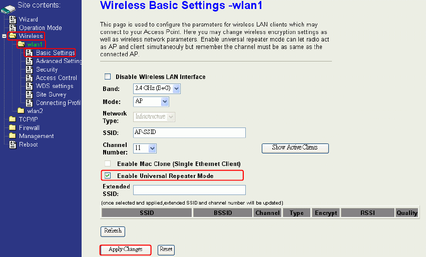
Configuring Universal Repeater
This device can be configured as a Repeater. In this mode, the device can extend
available wireless range of other AP let user can link the network that they want, Also the
device working as AP and Repeater same time.
Following two ways describe how to make Universal Repeater effective.
1. Enable Universal Repeater Mode and then click Apply Changes button to take effective.
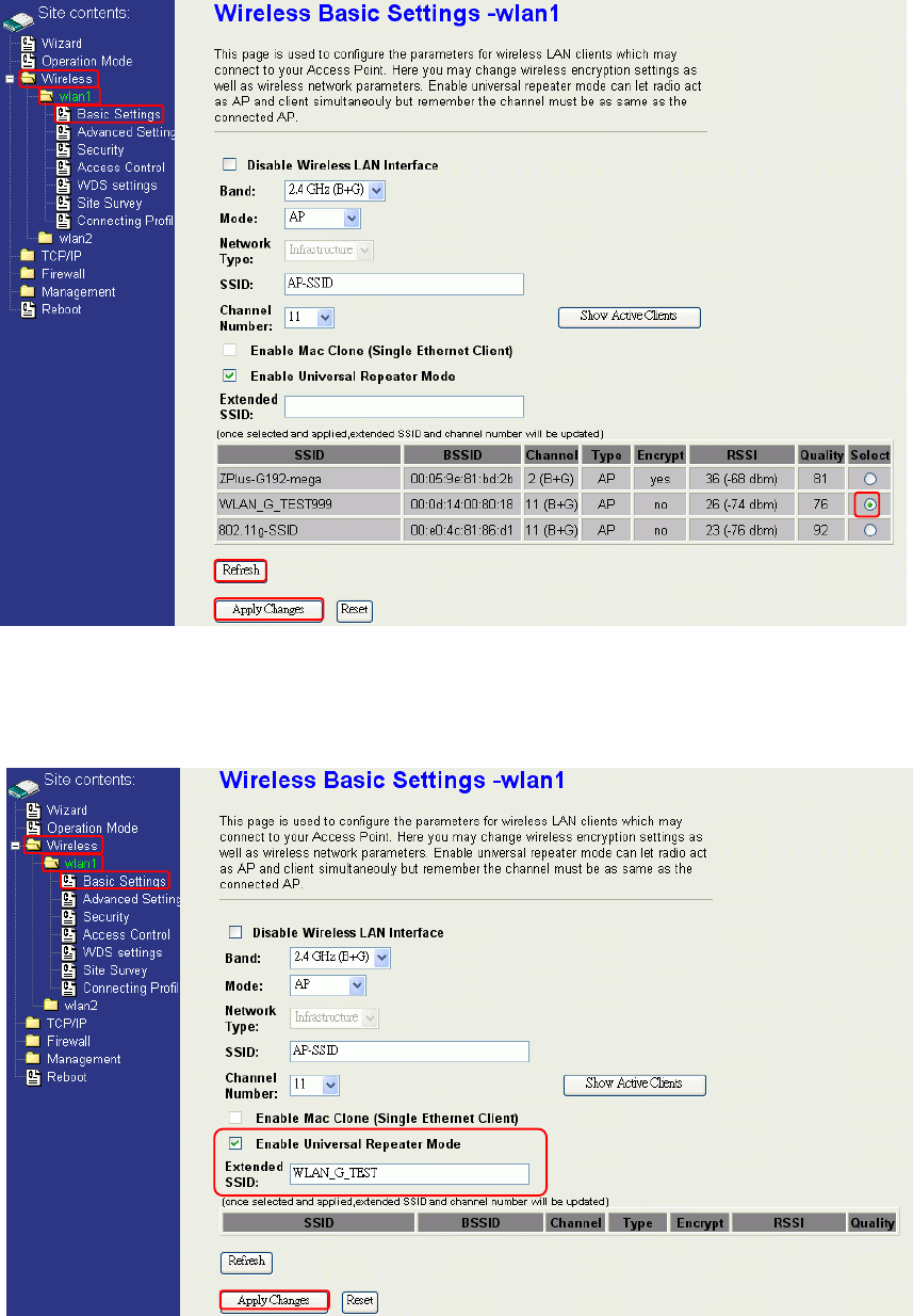
After apply change, you can click Refresh button to show the nearby APs in the Table.
You can select a SSID in the Table that you want and then click Apply Changes button to
take effective.
1
2
32
Note: Under AP、WDS and AP+WDS mode, The Universal Repeater can take effective.
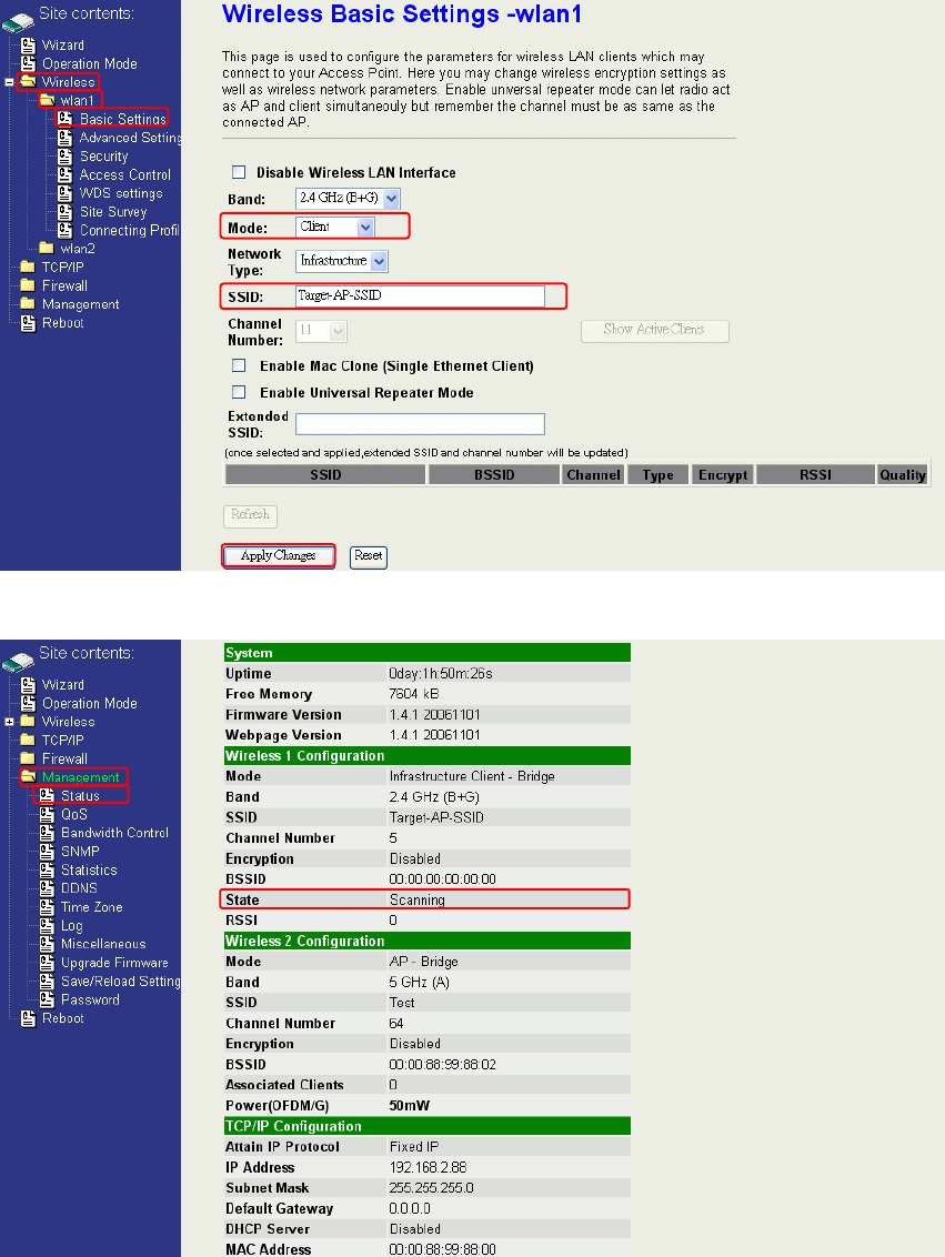
2. Enter specific SSID in the Extended SSID field and then click Apply Changes button to
take effective.
4
3
5
33
Configuring as WLAN Client Adapter
This device can be configured as a wireless Ethernet adapter. In this mode, the device
can connect to the other wireless stations (Ad-Hoc network type) or Access Point
(Infrastructure network type) and you don’t need to install any driver.
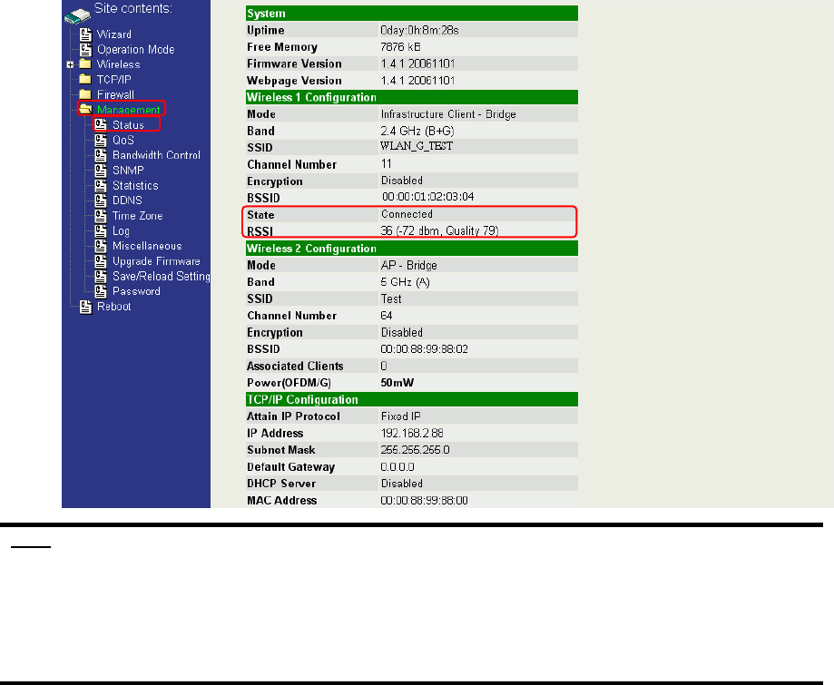
Quick start to configure
Step 1. In “Basic Settings” page, change the Mode to “Client” mode. And key in the SSID of the
AP you want to connect then press “Apply Changes” button to apply the change.
Step 2. Check the status of connection in “Status” web page
1
2
3

34
The alternative way to configure as following:
Step 1. In “Wireless Site Survey” page, select one of the SSIDs you want to connect and then
press “Connect” button to establish the link.
Step 2. If the linking is established successfully. It will show the message “Connect
successfully”. Then press “OK”.
Step 3. Then you can check the linking information in “Status” page.
1
2
35
Note :
If the available network requires authentication and data encryption, you need to
setup the authentication and encryption before step1 and all the settings must be as
same as the Access Point or Station. About the detail authentication and data
encryption settings, please refer the security section.
Authentication Type
In client mode, the device also supports two Authentication Types “Open system” and
“Shared Key”. Although the default setting is “Auto”, not every Access Points can
support “Auto” mode. If the authentication type on the Access Point is knew by user,
we suggest to set the authentication type as same as the Access Point.
Data Encryption
In client mode, the device supports WEP and WPA Personal/Enterprise except WPA2
mixed mode data encryption. About the detail data encryption settings, please refer the
security section.
36
Ch 4. WLAN 2 Wireless Configuration
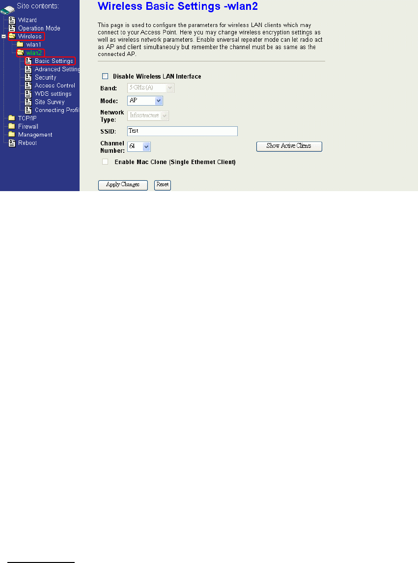
Basic Settings
Disable Wireless LAN Interface
Disable the wireless interface of device
Band:
The device supports 5GHz (A) mixed modes.
Mode:
The radio of device supports different modes as following:
1. AP
The radio of device acts as an Access Point to serves all wireless clients to join a
wireless local network.
2. Client
Support Infrastructure and Ad-hoc network types to act as a wireless adapter.
3. WDS
Wireless Distribution System, this mode serves as a wireless repeater, only devices
with WDS function supported can connect to it, all the wireless clients can’t survey and
connect the device when the mode is selected.
4. AP+WDS
Support both AP and WDS functions, the wireless clients and devices with WDS
function supported can survey and connect to it.
Network Type:
Infrastructure:
This type requires the presence of 802.11a Access Point. All communication is done via the
Access Point.
37
Ethernet
AP
AP Client #2
AP Client #1
Ad Hoc:
This type provides a peer-to-peer communication between wireless stations. All the
communication is done from Client to Client without any Access Point involved. Ad Hoc networking
must use the same SSID and channel for establishing the wireless connection.
PC #3 PC #2
AP Client #1
AP Client #2AP Client #3
PC #1
In client mode, the device can’t support the Router mode function including Firewall
and WAN settings.
SSID:
The SSID is a unique identifier that wireless networking devices use to establish and
maintain wireless connectivity. Multiple access point/bridges on a network or sub-network
can use the same SSID. SSIDs are case sensitive and can contain up to 32 alphanumeric
characters. Do not include spaces in your SSID.
Channel Number:
The following table is the available frequencies (in MHz) for the 5-GHz radio:
Regulatory Domains
Channel
Identifier
Frequency in
MHz Americas (-A) Japan (-J) Singapore (-S) Taiwan (-T)
34 5170 √
36 5180 √
38 5190 √

38
40 5200 √
42 5210 √
44 5220 √
46 5230 √
48 5240 √
52 5260 √
56 5280 √
60 5300 √
64 5320 √
149 5745 √
153 5765 √
157 5785 √
161 5805 √
165 5825 √
Associated Client:
Show the information of active wireless client stations that connected to the device.
Advanced Settings
These settings are only for more technically advanced users who have sufficient
knowledge about wireless LAN. These settings should not be changed unless you
know what effect the changes will have on your device. The default setting is optimized
for the normal operation. For specific application, setting configuration will required
highly attention to reach optimistic condition.
Note:
Any unreasonable value change to default setting will reduce the throughput of the
device.

39
Authentication Type
The device supports two Authentication Types “Open system” and “Shared Key”. When you
select “Share Key”, you need to setup “WEP” key in “Security” page (See the next section).
The default setting is “Auto”. The wireless client can associate with the device by using one
of the two types.
Fragment Threshold
The fragmentation threshold determines the size at which packets are fragmented (sent as
several pieces instead of as one block). Use a low setting in areas where communication is
poor or where there is a great deal of radio interference. This function will help you to
improve the network performance.
RTS Threshold
The RTS threshold determines the packet size at which the radio issues a request to send
(RTS) before sending the packet. A low RTS Threshold setting can be useful in areas where
many client devices are associating with the device, or in areas where the clients are far
apart and can detect only the device and not each other. You can enter a setting ranging
from 0 to 2347 bytes.
Beacon Interval
The beacon interval is the amount of time between access point beacons in mini-seconds.
The default beacon interval is 100.
ACK Timeout
The default ACK timeout is 50. You may need to change this value due to the environment
or distance.
Client Expired Time
40
Not applicable for WLAN 2.
MTU Size
Maximum Transmission Unit, the default MTU size is 1500. The MTU setting controls the
maximum Ethernet packet size your PC will send. Why a limit? Because although larger
packets can be constructed and sent, your ISP and Internet backbone routers and
equipment will fragment any larger than their limit, then these parts are re-assembled by the
target equipment before reading. This fragmentation and re-assembly is not optimal. You
may need to change the MTU for optimal performance of your wireless LAN traffic.
Data Rate
The standard IEEE 802.11a supports 6, 9, 12, 18, 24, 36, 48 and 54 Mbps data rates. You
can choose the rate that the device uses for data transmission. The default value is “auto”.
The device will use the highest possible selected transmission rate.
Preamble Type
The preamble is part of the 802.11 frame and is PHY dependant. All 802.11a systems
support the long preamble. The short preamble (optional) maybe used to improve
throughput when all stations on the network support the short preamble.
Broadcast SSID
Broadcasting the SSID will let your wireless clients find the device automatically. If you are
building a public Wireless Network, disable this function can provide better security. Every
wireless stations located within the coverage of the device must connect this device by
manually configure the SSID in your client settings.
IAPP (Inter-Access Point Protocol)
Not applicable for WLAN 2.
802.11g Protection
Not applicable for WLAN 2.
Block WLAN Relay (Isolate Client)
The device supports isolation function. If you are building a public Wireless Network, enable
this function can provide better security. The device will block packets between wireless
clients (relay). All the wireless clients connected to the device can’t see each other.
Aggregation Mode
This is a proprietary Ralink (802.11a chipset in the DLB70xx) aggregation setting that allows
for jumbo frames consisting of multiple smaller frames that increases throughput between
Ralink stations.
Tx Burst Mode
This is a proprietary Ralink (802.11a chipset in the device) burst setting and allows very
small networks (1~3 clients) to transmit at higher speeds. In larger networks, this will result
in degraded performance.
41
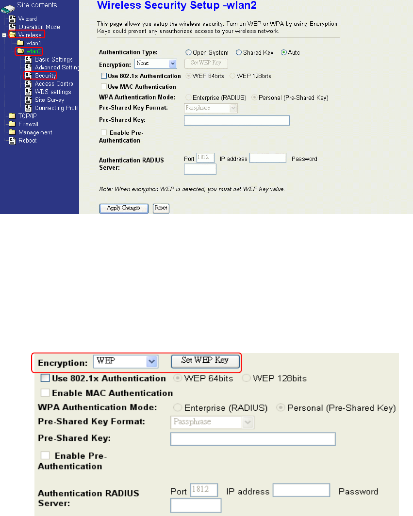
Configuring Wireless Security
This device provides complete wireless security function include WEP, 802.1x, WPA-TKIP,
WPA2-AES and WPA2-Mixed in different mode (see the Security Support Table).
The default security setting of the encryption function is disabled. Choose your preferred
security setting depending on what security function you need.
WEP Encryption Setting
Wired Equivalent Privacy (WEP) is implemented in this device to prevent unauthorized
access to your wireless network. The WEP setting must be as same as each client in your
wireless network. For more secure data transmission, you can change encryption type to
“WEP” and click the “Set WEP Key” button to open the “Wireless WEP Key setup”
page.
When you decide to use the WEP encryption to secure your WLAN, please refer to the
following setting of the WEP encryption:
64-bit WEP Encryption:64-bit WEP keys are as same as the encryption method of
40-bit WEP. You can input 10 hexadecimal digits (0~9, a~f or A~F) or 5 ACSII chars.
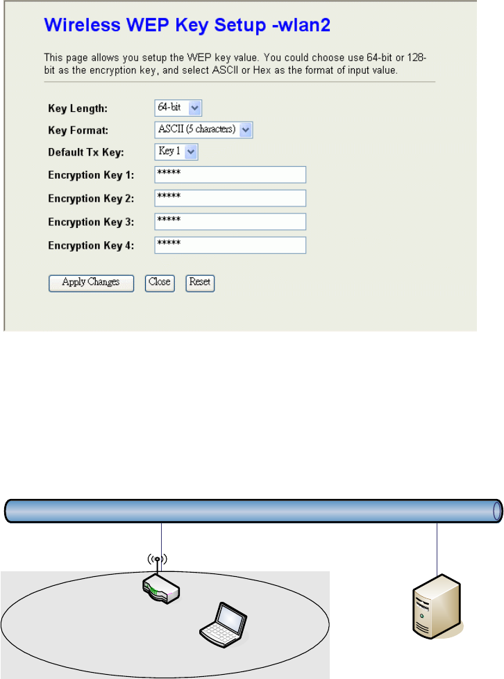
42
128-bit WEP Encryption:128-bit WEP keys are as same as the encryption method of
104-bit WEP. You can input 26 hexadecimal digits (0~9, a~f or A~F) or 10 ACSII chars.
The Default Tx Key field decides which of the four keys you want to use in your WLAN
environment.
WEP Encryption with 802.1x Setting
The device supports external RADIUS Server that can secure networks against
unauthorized access. If you use the WEP encryption, you can also use the RADIUS server
to check the admission of the users. By this way every user must use a valid account before
accessing the Wireless LAN and requires a RADIUS or other authentication server on the
network. An example is shown as following.
Ethernet
RADIUS Server
Wireless Station
AP
You should choose WEP 64 or 128 bit encryption to fit with your network environment first.
Then add user accounts and the target device to the RADIUS server. In the device , you
need to specify the IP address、Password (Shared Secret) and Port number of the target
RADIUS server.
43
WPA Encryption Setting
WPA feature provides a high level of assurance for end-users and administrators that their
data will remain private and access to their network restricted to authorized users. You can
choose the WPA encryption and select the Authentication Mode.
WPA Authentication Mode
This device supports two WPA modes. For personal user, you can use the Pre-shared Key
to enhance your security setting. This mode requires only an access point and client station
that supports WPA-PSK. For Enterprise, authentication is achieved via WPA RADIUS Server.
You need a RADIUS or other authentication server on the network.
Enterprise (RADIUS):
When WPA Authentication mode is Enterprise (RADIUS), you have to add user accounts
and the target device to the RADIUS Server. In the device , you need to specify the IP
address、Password (Shared Secret) and Port number of the target RADIUS server.
Pre-Share Key:
This mode requires only an access point and client station that supports WPA-PSK. The
WPA-PSK settings include Key Format, Length and Value. They must be as same as
each wireless client in your wireless network. When Key format is Passphrase, the key
value should have 8~63 ACSII chars. When Key format is Hex, the key value should have
64 hexadecimal digits (0~9, a~f or A~F).