Zinwell ZW-N5310 IEEE802.11abgn Wireless Router User Manual
Zinwell Corporation IEEE802.11abgn Wireless Router
UserManual.wiki
>
Zinwell
>
ZW N5310 User Manual
User manual
Navigation menu
Upload a User Manual
Namespaces
Wiki Guide
HTML
PDF
Info
Views
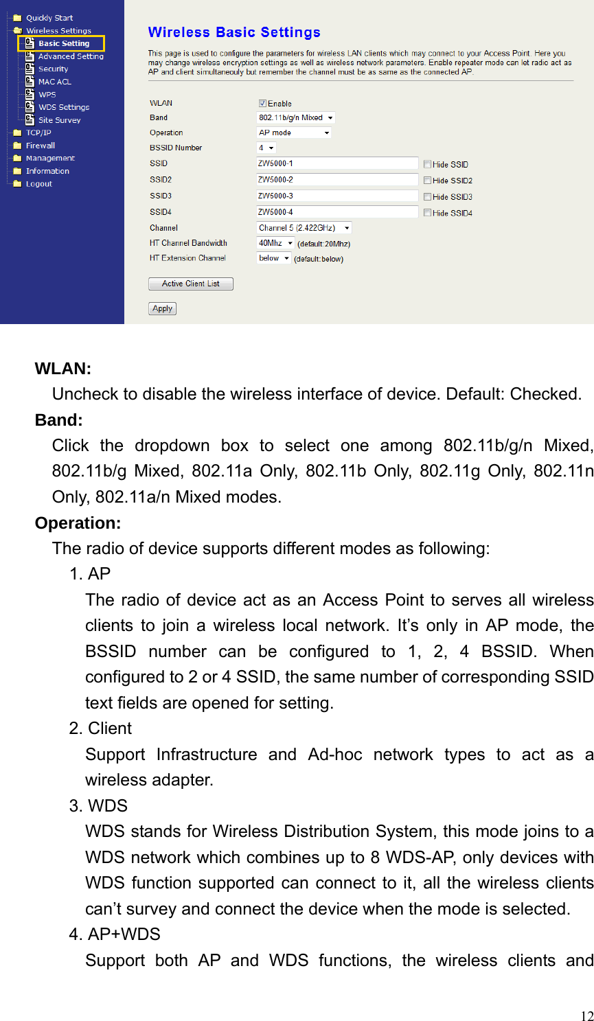
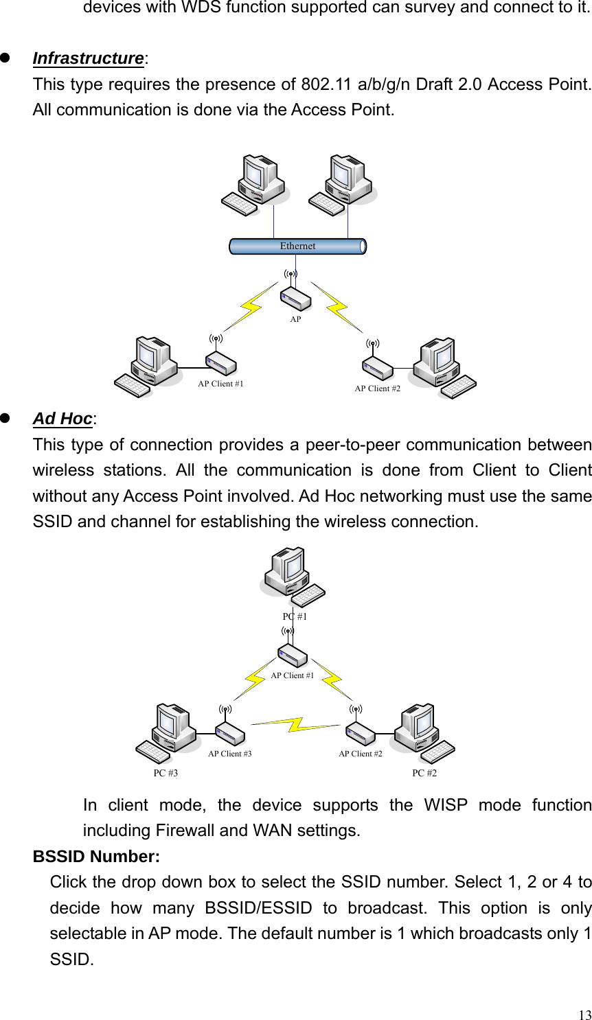
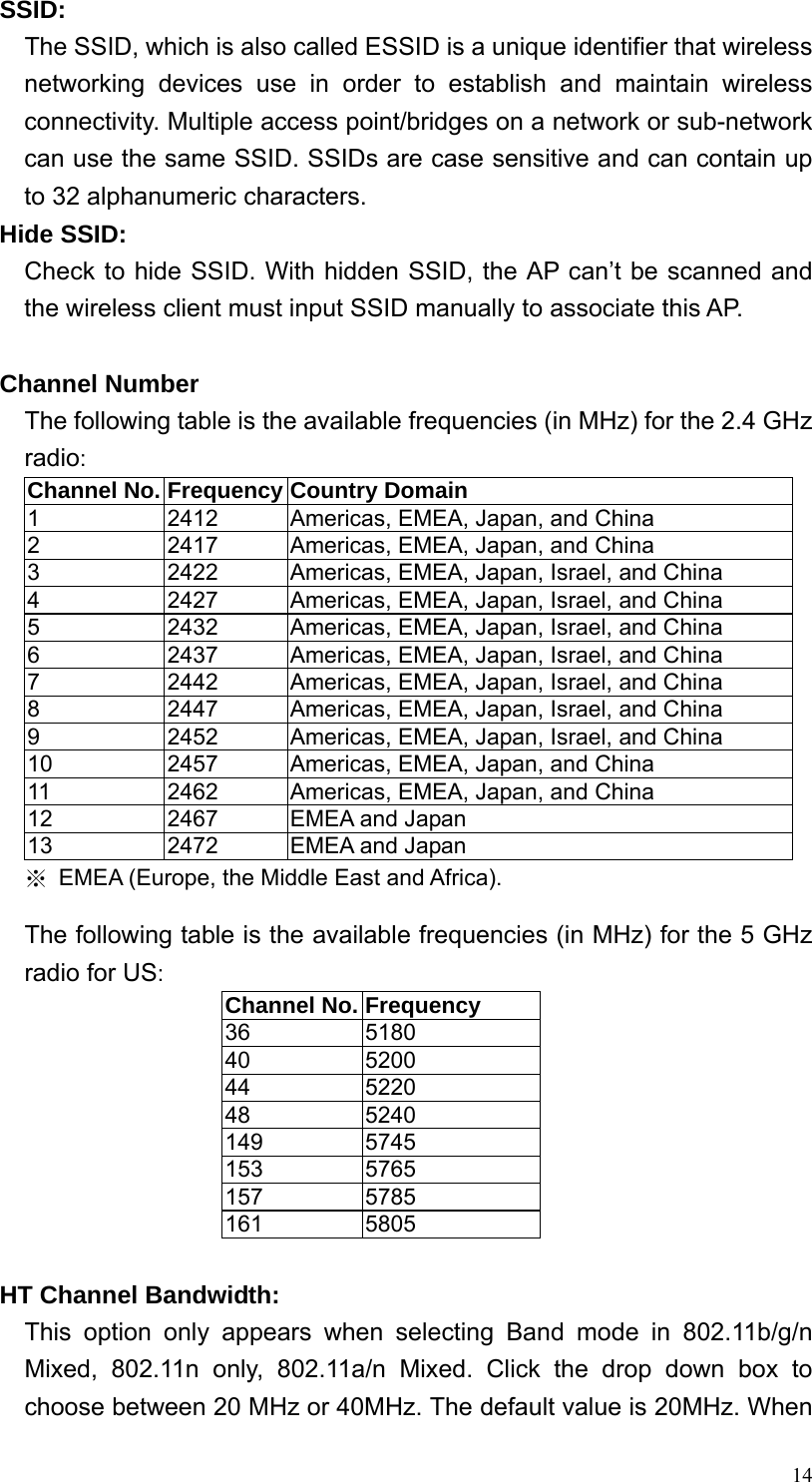
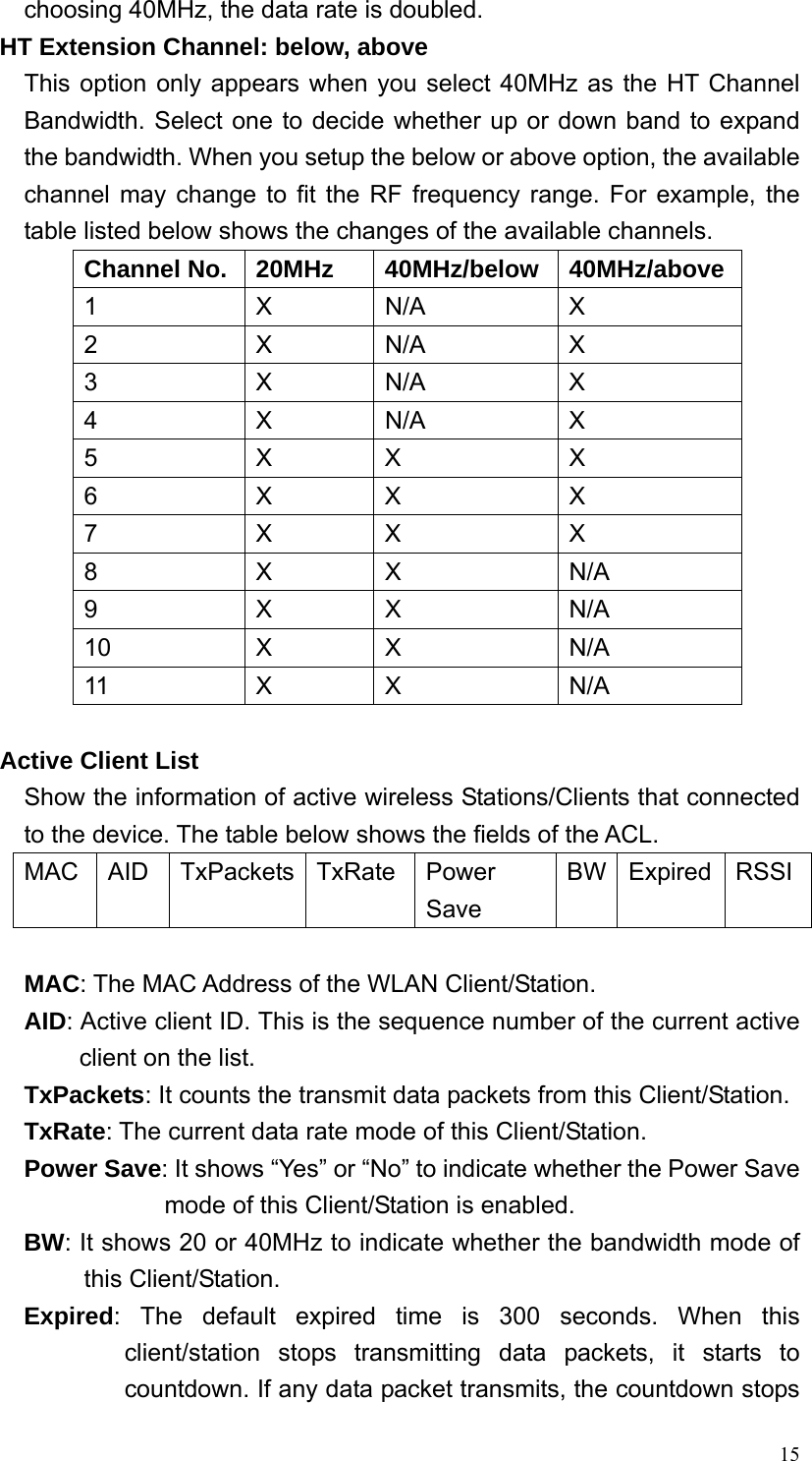
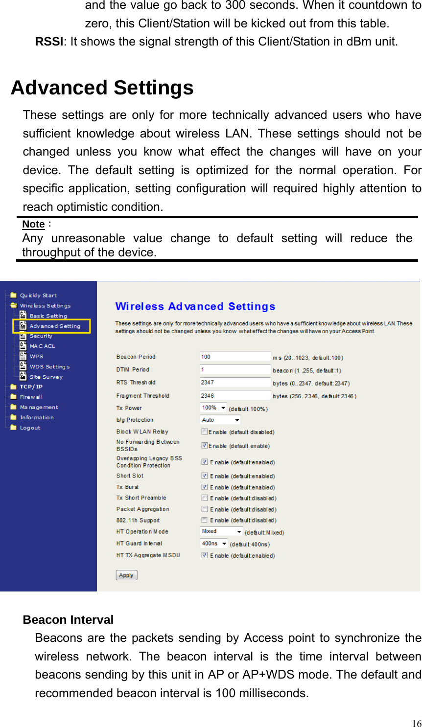
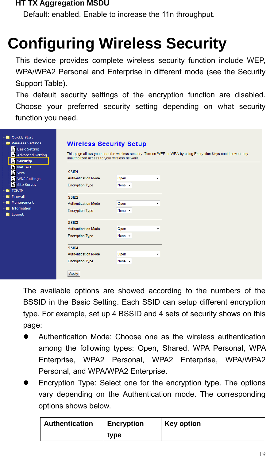
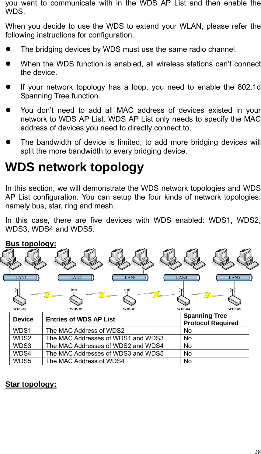
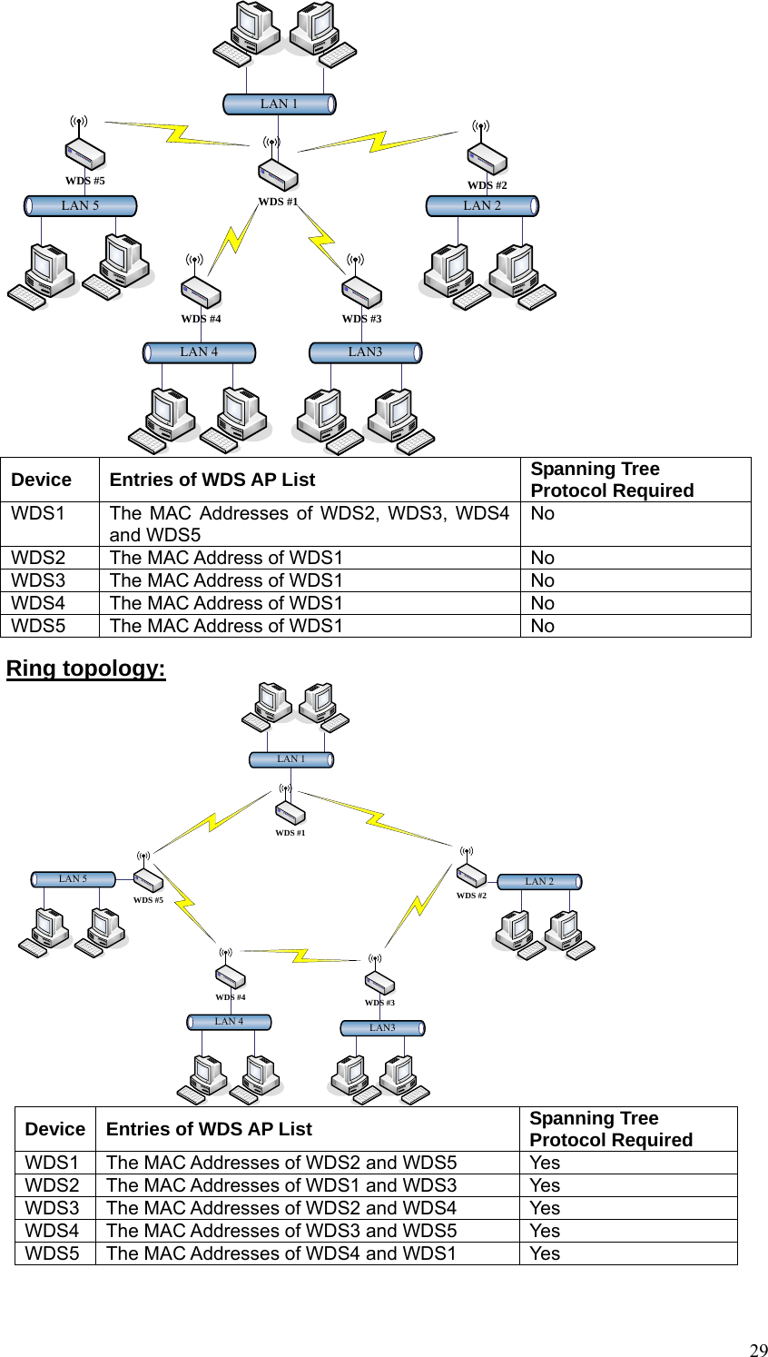
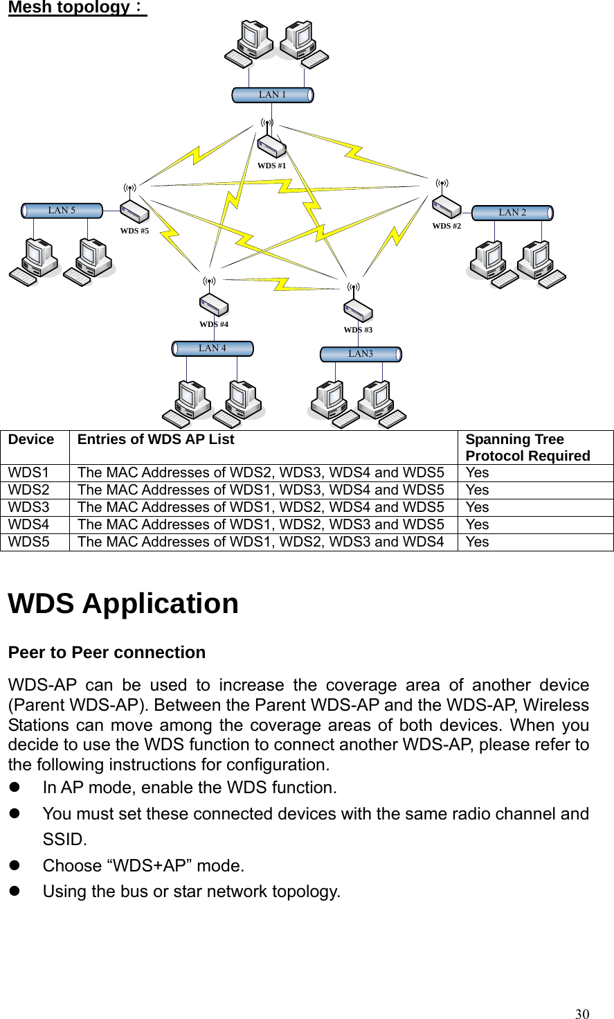
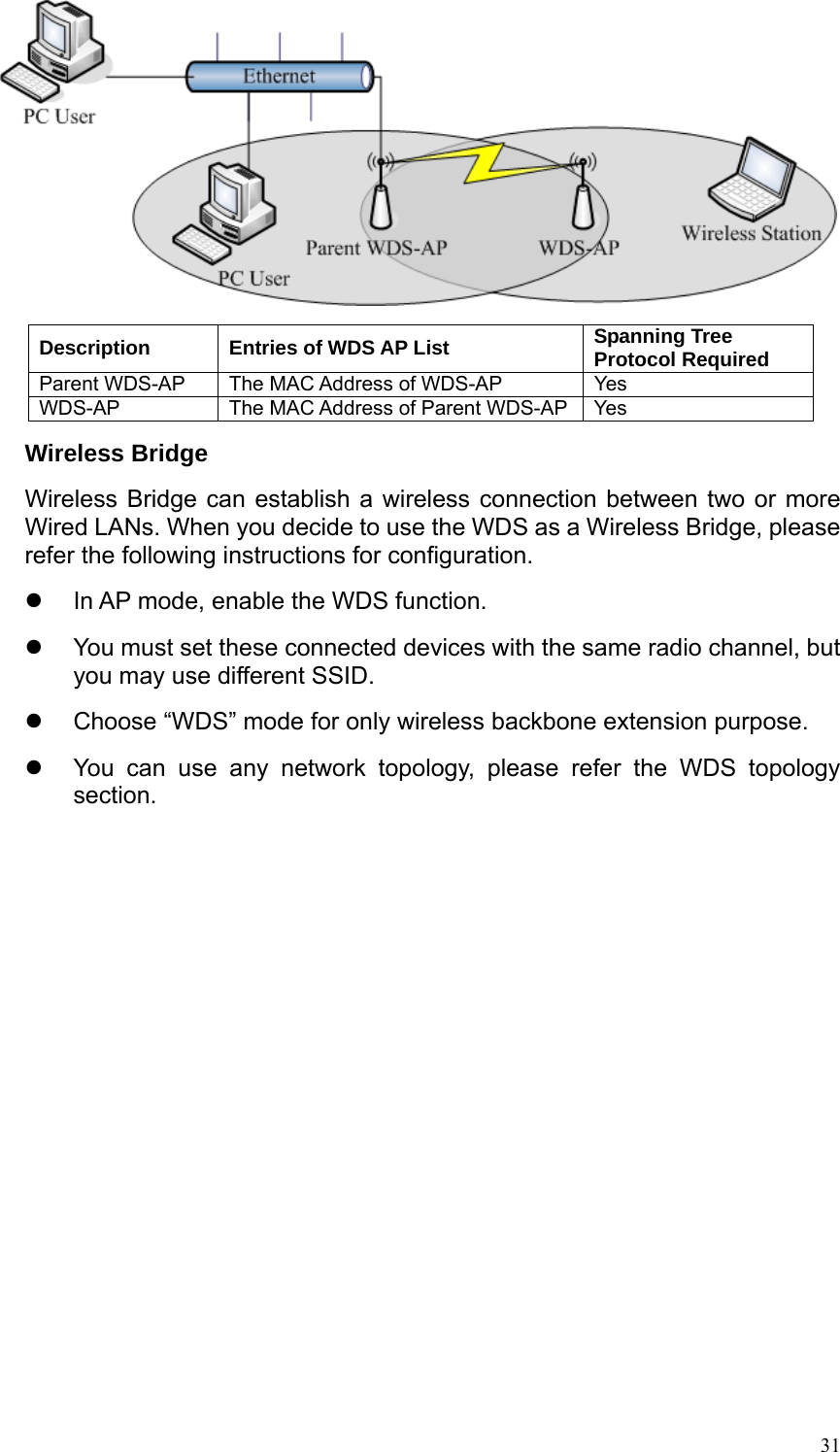
User Manual
Discussion / Help
Navigation