Zinwell ZW-N5310 IEEE802.11abgn Wireless Router User Manual
Zinwell Corporation IEEE802.11abgn Wireless Router
Zinwell >
User manual

Wireless LAN Device Series
802.11n Draft 2.0 Multi-Mode AP
ZW-N5310 User’s Manual
Version. 1 (2008.05.14)
1
TABLE OF CONTENTS
NOTICE..................................................................................................................................................3
PREFACE ...............................................................................................................................................5
CH 1. ZW-5310 INSTALLATION........................................................................................................6
PACKING LIST.......................................................................................................................................6
CONNECTORS, BUTTONS AND LEDS....................................................................................................6
HARDWARE INSTALLATION ..................................................................................................................7
CH 2. FIRST TIME CONFIGURATION ............................................................................................7
BEFORE START TO CONFIGURE .............................................................................................................7
KNOWING THE NETWORK APPLICATION ...............................................................................................8
SETUP WIZARD...................................................................................................................................10
BASIC SETTINGS ................................................................................................................................. 11
ADVANCED SETTINGS .........................................................................................................................16
CONFIGURING WIRELESS SECURITY ...................................................................................................19
MAC ACL .........................................................................................................................................22
WPS...................................................................................................................................................22
OPTIONS EXPLANATIONS ....................................................................................................................23
WPS CONFIGURATION STEPS .............................................................................................................24
SITE SURVEY ......................................................................................................................................25
CONFIGURING AS WLAN CLIENT ADAPTER .......................................................................................25
QUICK START TO CONFIGURE ..............................................................................................................25
CH 3. CONFIGURING WDS..............................................................................................................27
WDS NETWORK TOPOLOGY................................................................................................................28
WDS APPLICATION.............................................................................................................................30
CH 4. ADVANCED CONFIGURATIONS .........................................................................................32
CONFIGURING LAN TO WA N FIREWALL ............................................................................................32
PORT FILTERING .................................................................................................................................32
IP FILTERING ......................................................................................................................................33
MAC FILTERING.................................................................................................................................33
NAT (NETWORK ADDRESS TRANSLATION).........................................................................................33
CONFIGURING PORT FORWARDING (VIRTUAL SERVER)..............................................................................34
CONFIGURING DMZ ...........................................................................................................................34
CONFIGURING WA N INTERFACE.........................................................................................................35
STATIC IP............................................................................................................................................35
DHCP CLIENT (DYNAMIC IP).............................................................................................................36
PPPOE................................................................................................................................................37
2
PPTP..................................................................................................................................................37
CONFIGURING DHCP SERVER ............................................................................................................38
STATIC ROUTE SETUP .........................................................................................................................39
DYNAMIC ROUTE SETUP ....................................................................................................................40
UPNP.................................................................................................................................................40
VPN PASS-THROUGH..........................................................................................................................40
CH5. THE MANAGEMENT...............................................................................................................41
MISCELLANEOUS ................................................................................................................................41
UPLOAD SCRIPT..................................................................................................................................42
SNMP ................................................................................................................................................42
DDNS ................................................................................................................................................45
TIME ZONE .........................................................................................................................................45
QOS / BANDWIDTH SETTING ...............................................................................................................46
SYSTEM LOG SETTING ........................................................................................................................48
PING TEST ..........................................................................................................................................48
SAV E /RELOAD SETTINGS ....................................................................................................................49
UPGRADE FIRMWARE .........................................................................................................................49
PASSWORD SETUP...............................................................................................................................50
THE INFORMATION .............................................................................................................................51
SYSTEM INFORMATION .......................................................................................................................52
WIRELESS INFORMATION....................................................................................................................52
ROUTING TABLE .................................................................................................................................52
PACKET STATICS .................................................................................................................................53
SYSTEM LOG ......................................................................................................................................53
LOGOUT..............................................................................................................................................53
LOGOUT..............................................................................................................................................53
REBOOT..............................................................................................................................................53
3
Notice
FCC Warning
Changes or modifications to this unit not expressly approved by the party
responsible for compliance could void the user authority to operate the
equipment.
This device complies with Part 15 of the FCC Rules. Operation is subject to the
following two conditions: (1) This device may not cause harmful interference,
and (2) this device must accept any interference received, including
interference that may cause undesired operation.
The user’s manual or instruction manual for an intentional or unintentional
radiator shall caution the user that changes or modifications not expressly
approved by the party responsible for compliance could void the user’s
authority to operate the equipment.
FCC Statement
This equipment has been tested and found to comply with the limits for a Class
B digital device, pursuant to Part 15 of the FCC Rules. These limits are
designed to provide reasonable protection against harmful interference in a
residential installation. This equipment generates uses and can radiate radio
frequency energy and, if not installed and used in accordance with the
instructions, may cause harmful interference to radio communications.
However, there is no guarantee that interference will not occur in a particular
installation. If this equipment does cause harmful interference to radio or
television reception, which can be determined by turning the equipment off and
on, the user is encouraged to try to correct the interference by one or more of
the following measures:
z Reorient or relocate the receiving antenna.
z Increase the separation between the equipment and receiver.
z Connect the equipment into an outlet on a circuit different from that to
which the receiver is connected.
z Consult the dealer or an experienced radio/TV technician for help.
FCC RF Radiation Exposure Statement
This equipment complies with FCC radiation exposure limits set forth for an
uncontrolled environment. This equipment should be installed and operated
with minimum distance 20cm between the radiator & your body. For product
available in the USA/Canada market, only channel 1~11 can be operated.
4
Selection of other channels is not possible. The antenna(s) used for this
transmitter must not be co-located or operating in conjunction with any other
antenna or transmitter. Shielded interface cables must be used in order to
comply with emission limits.
Channel
The Wireless Channel sets the radio frequency used for communication.
z Access Points use a fixed Channel. You can select the Channel used.
This allows you to choose a Channel which provides the least interference
and best performance. In the USA and Canada, 11channel are available.
If using multiple Access Points, it is better if adjacent Access Points use
different Channels to reduce interference.
z In “Infrastructure” mode, Wireless Stations normally scan all Channels,
looking for an Access Point. If more than one Access Point can be used,
the one with the strongest signal is used. (This can only happen within an
ESS.)
z If using “Ad-hoc” mode (no Access Point), all Wireless stations should be
set to use the same Channel. However, most Wireless stations will still
scan all Channels to see if there is an existing “Ad-hoc” group they can
join.
Note:
This equipment marketed in USA is restricted by firmware to only operate on
2.4GHz channel 1-11, also with UNII band, only band 1 (5.15-5.25G) & band 4
(5.745-5.805G) can be used. In addition, the UNII band 1 (5.15-5.25GHz) can
be indoor used only.
CE Statement
ZINWELL, hereby declares that this device is in compliance with the essential
requirement and other relevant provisions of the R&TTE Directive 1999/5/EC.
This device will be sold in the following EEA countries:Austria, Italy, Belgium,
Liechtenstein, Denmark, Luxembourg, Finland, Netherlands, France, Norway,
Germany, Portugal, Greece, Spain, Iceland, Sweden, Ireland, United Kingdom,
Cyprus, Czech Republic, Estonia, Hungary, Latvia, Lithuania, Malta, Slovakia,
Poland, Slovenia, Bulgaria, Romania.
5
Preface
This guide is for the networking professional who installs and manages the
Zinwell ZW-5310 product hereafter referred to as the “device”. To use this
guide, you should have experience working with the TCP/IP configuration and
be familiar with the concepts and terminology of wireless local area networks.
6
Ch 1. ZW-5310 Installation
Packing List
Before starting the installation of the device, please make sure the package
contains the following items:
● ZW-5310 Multi-Mode AP unit * 1
● Power Adapter * 1
● RJ-45 Cable * 1
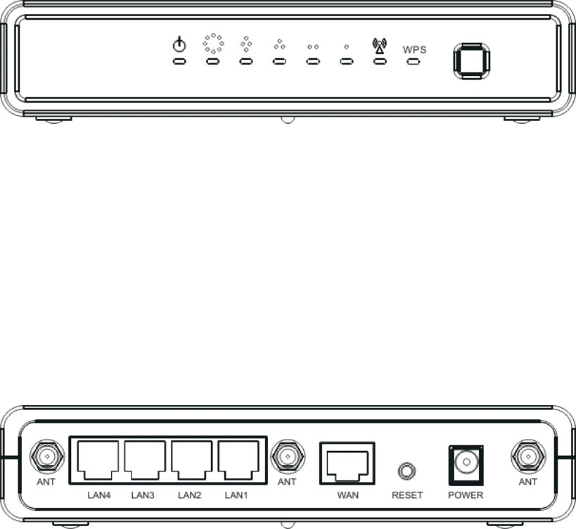
Connectors, Buttons and LEDs
Front Panel
From Left to right:
Power LED: Red LED lights when power on.
WAN: Orange LED lights when the Ethernet port is plugged and flashes when
it is transmitting.
LAN 4/3/2/1: Green LED lights when the respective Ethernet port is plugged
and flashes when it is transmitting.
WLAN: Green LED flashes when WLAN is working.
WPS LED: Blue LED lights when the WPS button is pushed.
WPS Button: Press it to enable PBC (Press Button Communication) for WPS
authentication.
Back Panel
7
From left to right:
Antenna port 1/2/3: This SMA Reverse allows the user to connect antenna or
RF cable. Please connect all three antennas into it.
LAN 4/3/2/1: 4 Ethernet ports for the LAN connection.
WAN: Connect the Ethernet port from ISP such as Adsl ITU-R, Cable MODEM.
Reset Button: Press Reset button to revert it to factory default.
DC Jack: Please supply the power in 12V and 1A.
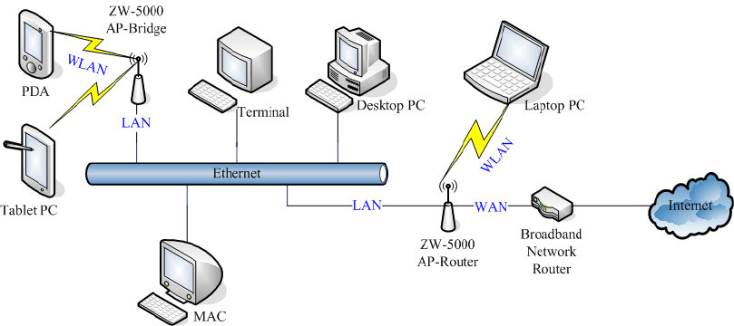
Hardware Installation
Once you check everything from the package, you can start to install the
device. You can use the wall mount hole on the bottom of the device to
mount the device on the wall, or just put the device on the desktop. The
administrator can refer to the figure below while in the process of
constructing your WLAN environment.
Ch 2. First Time Configuration
Before Start to Configure
The configuration of this device is through web-browser. To access the
configuration interfaces, make sure you are using a computer connected to
the same network as the device. The default IP address of the device is
8
192.168.1.254, and the subnet-mask is 255.255.255.0. We Recommend to
login with username: root and password: root for the first time configuration.
Please note that the DHCP server inside the device is default to up and
running. Do not have multiple DHCP servers in your network environment,
otherwise it will cause abnormal situation.
Knowing the Network Application
The device can act as the following roles, and it supports WDS (Wireless
Distribution System) function.
z Access Point
z WDS mode
z Bridge/Router
z WISP
z AP Client
The device provides 3 different operation modes and the wireless radio of
device can act as AP/Client/WDS. The operation mode is about the
communication mechanism between the wired Ethernet NIC and wireless
NIC. Following are the types of operation mode.
Router
The wired Ethernet (WAN) port is used to connect with ADSL/Cable modem
and the wireless NIC is used for your private WLAN. The other wired
Ethernet (LAN) port bridges to the private WLAN. The NAT is existed
between WAN and WLAN/LAN and all the wireless and wired clients share
the same public IP address through the WAN port to ISP. The default IP
configuration for WAN port is static IP. You can access the web server of
device through the default WAN IP address 172.1.1.1 and modify the setting
base on your ISP requirement.
Bridge
The WAN port will bridge to the other 4 LAN ports. Once the mode is
selected, all the WAN related functions will be disabled.
WISP (Wireless ISP)

9
This mode can let you access the AP of your wireless ISP and share the
same public IP address from your ISP to the PCs connecting with both the
wired Ethernet ports of the device. When setup as this mode, the wireless
radio will be client mode connecting to the AP of your ISP as the WAN
connection and then you can configure the WAN IP configuration to meet
your WISP requirement.
The wireless radio of the device acts as the following roles.
AP (Access Point)
The wireless radio of device serves as communications “hub” for wireless
clients and provides a connection to a wired LAN.
AP Client
This mode enables the establishment of connection with the other AP using
infrastructure/Ad-hoc networking types. With bridge operation mode, you
can directly connect one of the wired Ethernet port to your PC and the
device becomes a wireless adapter. And with WISP operation mode, you
can connect one of the wired Ethernet port to a hub/switch and all the PCs
connecting with hub/switch can share the same public IP address from your
ISP.
WDS (Wireless Distribution System)
This mode combines up to 8 AP to a single wireless network; the device
forwards the packets to another AP with WDS function. When this mode is
selected, all the wireless clients can’t survey and connect to the device. The
device only allows the WDS connection.
WDS+AP
This mode combines WDS plus AP modes, and it not only allows WDS
connections but also the wireless clients can survey and connect to the
device.
The following table shows the supporting combination of operation and
wireless radio modes.
Bridge Router WISP
AP V V X
WDS V V X
Client V X V
10
AP+WDS V V X
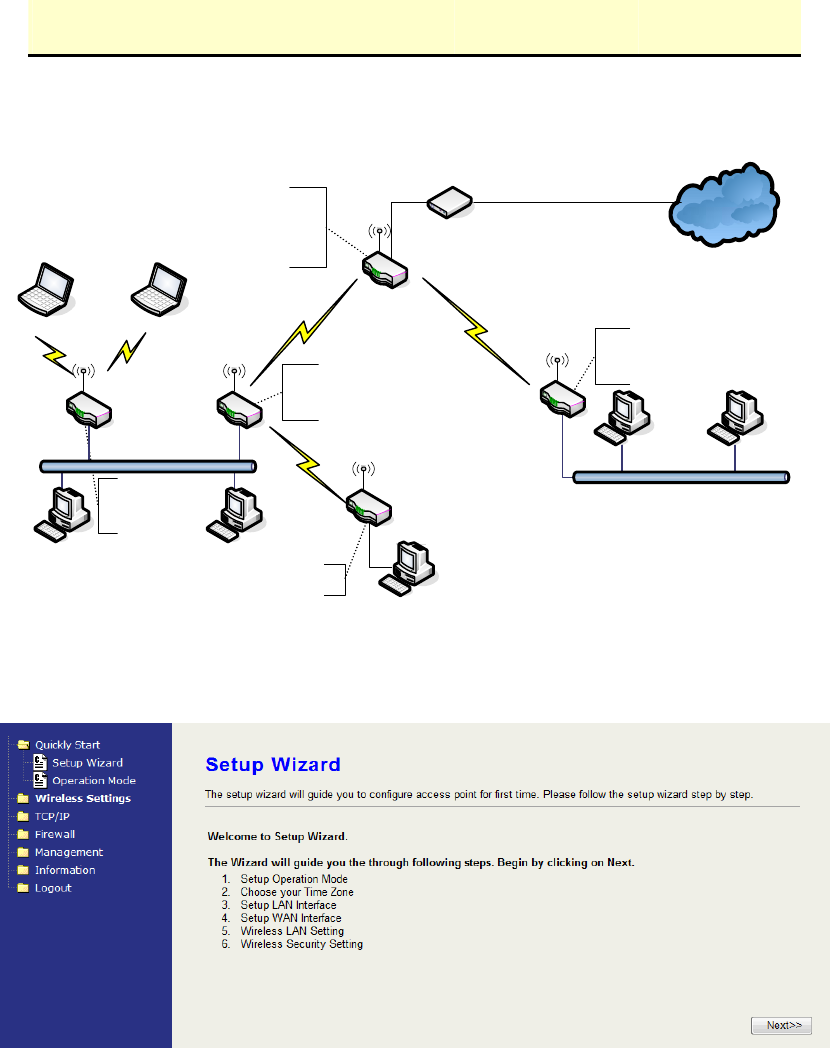
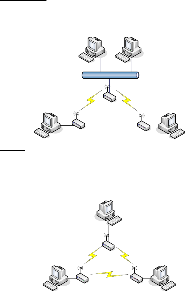
Hereafter are some topologies of network application for your reference.
Internet
192 . 168. 2.x
192.168.3.x192.168.3.x
192. 168.2.x 192. 168.2.x
DEV 1
LAN 192.168.2.254/24
WAN PPPoE connection
DEV 1
MAC Address of WLAN ( BSSID ) 000000042728
DHCP Server enabled ( IP Pool 192.168.2.1~ 253)
DEV 2
LAN 192.168.2. 202/24
Wireless Channel : 11 / SSID : DEV 2
MAC Address of WLAN ( BSSID ) 000000042692
DEV 5
LAN 192.168.2.205/24
DEV 4
LAN 192.168.3.1/24
WAN Dynamic IP address
DHCP Server enabled ( IP pool 192 . 168.3.2~254)
DEV 3
LAN 192. 168 .2.203/ 24
Channel : 5
SSID : DEV 3
Broadband
Modem
WISP
Bridge Mode
With
AP
Bridge Mode
With
Router Mode
With
WDS + AP
Wireless Channel : 11 / SSID :
192 . 168. 2.x192 . 168. 2.x
WDS + AP
Bridge Mode
Setup Wizard
When you login the device at the first time, please click the Setup Wizard for
configuration. Just follow the instruction of the web page and input every field.
It will take you through the settings. However, if you are not familiar with some
terms of WLAN, you may want to read the following section for the details of
each setting.
0. Welcome—click “Next” to continue.
1. Operation mode—select one mode among the modes below according to
your network environment.
11
z Router
z Bridge
z Wireless ISP
2. Time Zone Setting—input the Internet time setting. This device will update
time from NTP server.
z Time Zone: select your time zone.
z NTP Update Interval: select the time interval between every update
attempt.
z NTP Server 1: input your favorite NTP server.
z NTP Server 2: input the backup NTP server.
3. LAN Interface Setup
z IP Address: assign an IP Address for the device.
z Subnet Mask: enter the subnet mask.
4. WAN Interface Setup
z Static IP, DHCP, PPPoE, PPTP: Select one for your WAN type. Enter the
necessary information for each type.
z Allow webpage from WAN: Click to allow login the web configuration from
WAN.
5. Wireless Basic settings—setup the information including Band, Operation
mode, SSID and Channel.
6. Wireless Security Setup—Setup
Open, Shared, WEP Auto, WPA Personal, WPA2 Personal, WPA/WPA2
Personal
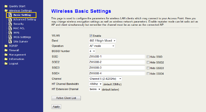
Basic Settings
12
WLAN:
Uncheck to disable the wireless interface of device. Default: Checked.
Band:
Click the dropdown box to select one among 802.11b/g/n Mixed,
802.11b/g Mixed, 802.11a Only, 802.11b Only, 802.11g Only, 802.11n
Only, 802.11a/n Mixed modes.
Operation:
The radio of device supports different modes as following:
1. AP
The radio of device act as an Access Point to serves all wireless
clients to join a wireless local network. It’s only in AP mode, the
BSSID number can be configured to 1, 2, 4 BSSID. When
configured to 2 or 4 SSID, the same number of corresponding SSID
text fields are opened for setting.
2. Client
Support Infrastructure and Ad-hoc network types to act as a
wireless adapter.
3. WDS
WDS stands for Wireless Distribution System, this mode joins to a
WDS network which combines up to 8 WDS-AP, only devices with
WDS function supported can connect to it, all the wireless clients
can’t survey and connect the device when the mode is selected.
4. AP+WDS
Support both AP and WDS functions, the wireless clients and
13
devices with WDS function supported can survey and connect to it.
z Infrastructure:
This type requires the presence of 802.11 a/b/g/n Draft 2.0 Access Point.
All communication is done via the Access Point.
Ethernet
AP
AP Client #2
AP Client #1
z Ad Hoc:
This type of connection provides a peer-to-peer communication between
wireless stations. All the communication is done from Client to Client
without any Access Point involved. Ad Hoc networking must use the same
SSID and channel for establishing the wireless connection.
PC #3 PC #2
AP Client #1
AP Client #2AP Client #3
PC #1
In client mode, the device supports the WISP mode function
including Firewall and WAN settings.
BSSID Number:
Click the drop down box to select the SSID number. Select 1, 2 or 4 to
decide how many BSSID/ESSID to broadcast. This option is only
selectable in AP mode. The default number is 1 which broadcasts only 1
SSID.

14
SSID:
The SSID, which is also called ESSID is a unique identifier that wireless
networking devices use in order to establish and maintain wireless
connectivity. Multiple access point/bridges on a network or sub-network
can use the same SSID. SSIDs are case sensitive and can contain up
to 32 alphanumeric characters.
Hide SSID:
Check to hide SSID. With hidden SSID, the AP can’t be scanned and
the wireless client must input SSID manually to associate this AP.
Channel Number
The following table is the available frequencies (in MHz) for the 2.4 GHz
radio:
Channel No. Frequency Country Domain
1 2412 Americas, EMEA, Japan, and China
2 2417 Americas, EMEA, Japan, and China
3 2422 Americas, EMEA, Japan, Israel, and China
4 2427 Americas, EMEA, Japan, Israel, and China
5 2432 Americas, EMEA, Japan, Israel, and China
6 2437 Americas, EMEA, Japan, Israel, and China
7 2442 Americas, EMEA, Japan, Israel, and China
8 2447 Americas, EMEA, Japan, Israel, and China
9 2452 Americas, EMEA, Japan, Israel, and China
10 2457 Americas, EMEA, Japan, and China
11 2462 Americas, EMEA, Japan, and China
12 2467 EMEA and Japan
13 2472 EMEA and Japan
※ EMEA (Europe, the Middle East and Africa).
The following table is the available frequencies (in MHz) for the 5 GHz
radio for US:
Channel No. Frequency
36 5180
40 5200
44 5220
48 5240
149 5745
153 5765
157 5785
161 5805
HT Channel Bandwidth:
This option only appears when selecting Band mode in 802.11b/g/n
Mixed, 802.11n only, 802.11a/n Mixed. Click the drop down box to
choose between 20 MHz or 40MHz. The default value is 20MHz. When

15
choosing 40MHz, the data rate is doubled.
HT Extension Channel: below, above
This option only appears when you select 40MHz as the HT Channel
Bandwidth. Select one to decide whether up or down band to expand
the bandwidth. When you setup the below or above option, the available
channel may change to fit the RF frequency range. For example, the
table listed below shows the changes of the available channels.
Channel No. 20MHz 40MHz/below 40MHz/above
1 X N/A X
2 X N/A X
3 X N/A X
4 X N/A X
5 X X X
6 X X X
7 X X X
8 X X N/A
9 X X N/A
10 X X N/A
11 X X N/A
Active Client List
Show the information of active wireless Stations/Clients that connected
to the device. The table below shows the fields of the ACL.
MAC AID TxPackets TxRate Power
Save
BW Expired RSSI
MAC: The MAC Address of the WLAN Client/Station.
AID: Active client ID. This is the sequence number of the current active
client on the list.
TxPackets: It counts the transmit data packets from this Client/Station.
TxRate: The current data rate mode of this Client/Station.
Power Save: It shows “Yes” or “No” to indicate whether the Power Save
mode of this Client/Station is enabled.
BW: It shows 20 or 40MHz to indicate whether the bandwidth mode of
this Client/Station.
Expired: The default expired time is 300 seconds. When this
client/station stops transmitting data packets, it starts to
countdown. If any data packet transmits, the countdown stops
16
and the value go back to 300 seconds. When it countdown to
zero, this Client/Station will be kicked out from this table.
RSSI: It shows the signal strength of this Client/Station in dBm unit.
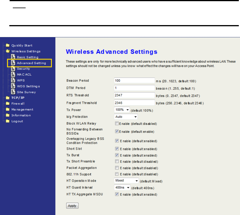
Advanced Settings
These settings are only for more technically advanced users who have
sufficient knowledge about wireless LAN. These settings should not be
changed unless you know what effect the changes will have on your
device. The default setting is optimized for the normal operation. For
specific application, setting configuration will required highly attention to
reach optimistic condition.
Note:
Any unreasonable value change to default setting will reduce the
throughput of the device.
Beacon Interval
Beacons are the packets sending by Access point to synchronize the
wireless network. The beacon interval is the time interval between
beacons sending by this unit in AP or AP+WDS mode. The default and
recommended beacon interval is 100 milliseconds.
17
DTIM Period
The default value of Delivery Traffic Indication Message is 1 beacon.
The DTIM which is in the beacon is to inform clients of the next window
for listening to broadcast and multicast messages.
RTS Threshold
The RTS threshold determines the packet size at which the radio issues
a request to send (RTS) before sending the packet. A low RTS
Threshold setting can be useful in areas where many client devices are
associating with the device, or in areas where the clients are far apart
and can detect only the device and not each other. You can enter a
setting ranging from 0 to 2347 bytes.
Fragment Threshold
The fragmentation threshold determines the size at which packets are
fragmented (sent as several pieces instead of as one block). Use a low
setting in areas where communication is poor or where there is a great
deal of radio interference. This function will help you to improve the
network performance.
Tx Power (RF transmit power)
The default Tx power is 100%. In case of shortening the distance and
the coverage of the wireless network, click the drop-down box to select
the smaller percentage. The level between each value is 10%.
b/g Protection
Default: Auto. You can select the other options including Always On,
Always Off. The B/G protection technology is CTS-To-Self. It will try to
reserve the throughput for 11g clients from 11b clients connecting to the
device as AP mode.
Block WLAN Relay (Client Isolation)
The device supports isolation function. If you are building a public
Wireless Network, enable this function can provide better security. The
device will block packets between wireless clients (relay). All the
wireless clients connected to the device can’t see each other.
No Forwarding Between BSSIDs
The device supports multi-SSID. You can decide whether the clients
associated to different SSID on the device can see each other. Enable
the option to block it. The Default value is enabled.
Overlapping Legacy BSS Condition Protection
Default: enabled
Enable it to maintain the legacy support while the device is in 11n mode.

18
Short Slot
Default: enabled. Reduce the waits after the collision time before
retransmitting. It will increase the throughput.
Tx Burst
Default: enabled. Enable it and the device will try this function when the
other associated AP/Client is available.
Tx Short Preamble
Default: enabled. Only requires disabling it when connecting some old
802.11 b wireless clients.
Packet Aggregation
Default: enabled. This is one of 802.11n technique to increase the data
throughput.
802.11h Support
Default: enabled. This function provides Dynamic Frequency Selection
(DFS) and the transmit power control (TPC) to 802.11a MAC.
HT Operation Mode
Default: Mixed (Mixed, Green Field).
Mixed mode: In this mode the device transmits the packets with
preamble compatible legacy (802.11 a/g), so they can be decoded by
legacy devices. The device receives and decodes both Mixed Mode
packets and legacy packets.
Green Field mode: the device transmits HT packets without legacy
compatible part. But the device receives and decodes both Green Field
and legacy packets.
HT Guard Interval
Default: 400ns. The 11n device inserts the Guard Interval into the signal.
You can choose the interval between 400ns and 800ns. The available
data rate modes are changed according to the Guard Interval.
Guard
Interval
Bandwidth Available Data Rate Mode (Mbps)
20MHz 144.4/130/115.6/ 86.7/72.2/65/57.8/43.3/28.9/21.7/
14.4/7.2
400ns
40MHz 300/270/240/180/150/135/120/90/60/45/30/15
20MHz 130/117/104/78/65/58/52/39/26/19.5/13/6.5
800ns
40MHz 270/243/216/162/135/
121.5/108/81/54/40.5/27/13.5
19
HT TX Aggregation MSDU
Default: enabled. Enable to increase the 11n throughput.
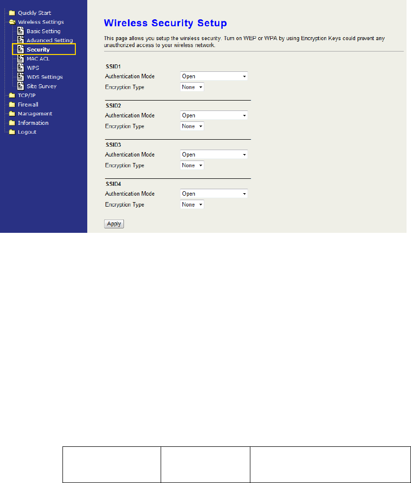
Configuring Wireless Security
This device provides complete wireless security function include WEP,
WPA/WPA2 Personal and Enterprise in different mode (see the Security
Support Table).
The default security settings of the encryption function are disabled.
Choose your preferred security setting depending on what security
function you need.
The available options are showed according to the numbers of the
BSSID in the Basic Setting. Each SSID can setup different encryption
type. For example, set up 4 BSSID and 4 sets of security shows on this
page:
z Authentication Mode: Choose one as the wireless authentication
among the following types: Open, Shared, WPA Personal, WPA
Enterprise, WPA2 Personal, WPA2 Enterprise, WPA/WPA2
Personal, and WPA/WPA2 Enterprise.
z Encryption Type: Select one for the encryption type. The options
vary depending on the Authentication mode. The corresponding
options shows below.
Authentication Encryption
type
Key option
20
Open None, WEP Default Key ID, Key type, Key
content
Shared/WEP
Auto
WEP Default Key ID, Key type, Key
content
WPA/WPA2
Personal
TKIP, AES,
TKIP/AES
Pass Phrase (8..32bytes), Hex
(64hex)
WPA/WPA2
Enterprise
TKIP, AES,
TKIP/AES
Radius Server
Network/Address/Port/Key
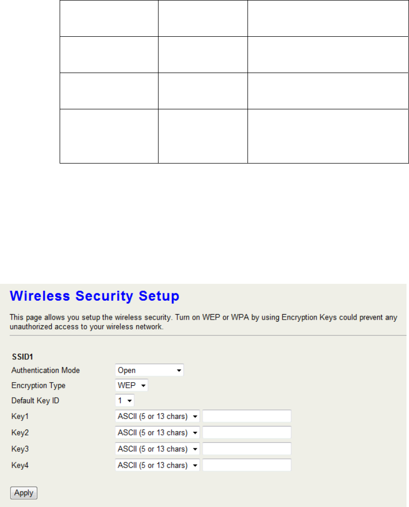
WEP Encryption Setting
Wired Equivalent Privacy (WEP) is implemented in this device to
prevent unauthorized access to your wireless network. The WEP setting
must be as same as each client in your wireless network.
z Authentication Type: Open, Shared and Auto. When choose
“Open” or “Shared”, all of the clients must select the same
authentication to associate this AP. If select “WEP Auto”, the clients
don’t have to use the same “Open” or “Shared” authentication.
They can choose any one to authenticate.
z Default Key ID: Select whether the Key ID as the default Key.
z Key 1/2/3/4: Select “ASCII (5 or 13 chars)” or “Hex (10 or 26 Hex)”
and then type the key in the text field.
64-bit WEP Encryption:64-bit WEP keys are as same as the
21
encryption method of 40-bit WEP. When input 10 hexadecimal
digits (0-9, a-f or A-F) or 5 ACSII chars as the key, it is using
64-bit WEP encryption.
128-bit WEP Encryption:128-bit WEP keys are as same as the
encryption method of 104-bit WEP. When input 26
hexadecimal digits (0-9, a-f or A-F) or 10 ACSII chars, it is
using 128-bit WEP encryption.
WPA Authentication Mode
This device supports six WPA modes including WPA Personal, WPA
Enterprise, WPA2 Personal, WPA2 Enterprise and additional
WPA/WPA2 Personal and WPA/WPA2 Enterprise. For individual and
residential user, it is recommended to select WPA or WPA2 Personal to
encrypt the link without additional RADIUS server. This mode requires
only an access point and client station that supports WPA-Pre Shared
Key. For Enterprise, authentication is achieved via WPA RADIUS Server.
You need a RADIUS or other authentication server on the network.
z WPA/WPA2 Personal:
Pre-Share Key:
Option: Pass Phrase (8-32bytes), Hex (64hex). This mode
requires only an access point and client station that supports
WPA-PSK. The WPA-PSK settings include Key Format, Length
and Value. They must be as same as each wireless client in your
wireless network. When Key format is Passphrase, the key value
should have 8-63 ACSII chars. When Key format is Hex, the key
value should have 64 hexadecimal digits (0-9, a-f or A-F).
z WPA/WPA2 Enterprise (RADIUS):
When WPA Authentication mode is Enterprise (RADIUS), you have to
add user accounts and the target device to the RADIUS Server. In the
device, you need to specify the Server Network, Server address,
Server Port and Server Key of the target RADIUS server.
Encryption Type: TKIP, AES, TKIP/AES. Select the
encryption type. When selecting TKIP/AES, the client can
use whether TKIP or AES for the authentication.
Pre-Authentication Support option: This option only appears
when selecting WPA2 or WPA/WPA2 Enterprise as the
authentication mode. Enable it to use this function.
Radius Server Network: WAN, LAN. Select the WAN or LAN
22
depends on whether the RADIUS server location is.
Radius Server Address: Input the IP Address of the Radius
server.
Radius Server Port: Input the port of the Radius server. The
default port is 1812.
Radius Server Key: Input the Authentication Key.
Ethernet
RADIUS Server
Wireless Station
AP
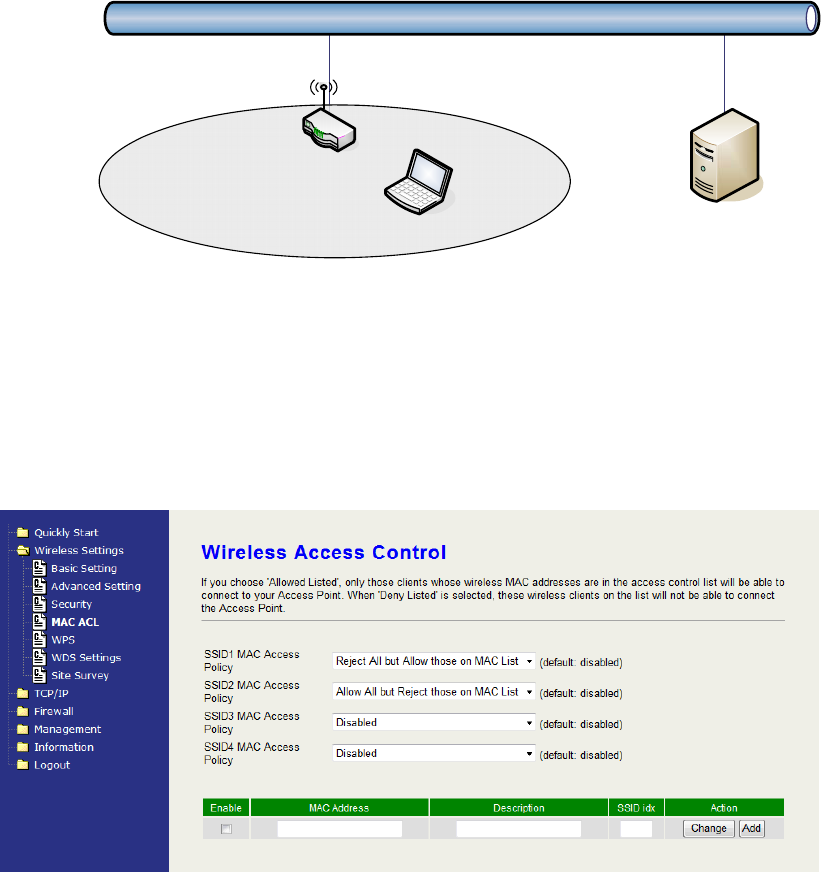
MAC ACL
This device can setup Access Control List to allow or reject wireless clients.
Select “Reject ALL but Allow those on MAC List” or “Allow ALL but Reject those
on MAC List” on each SSID and then input the information in the ACL.
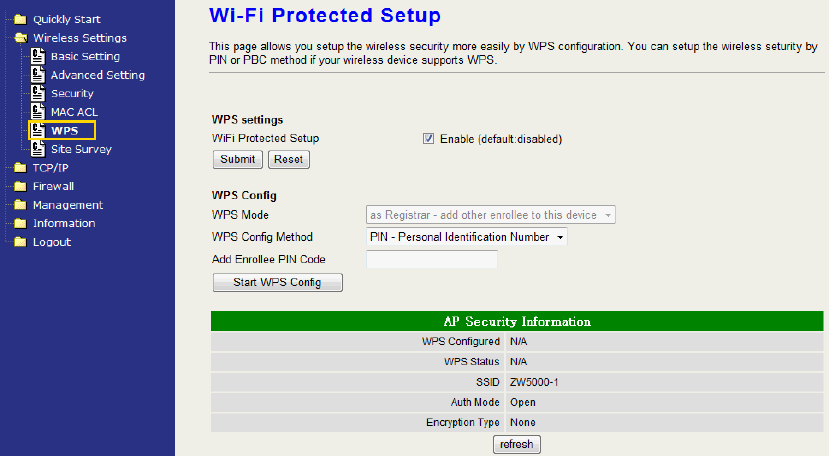
WPS
This device supports two kinds of WPS (Wi-Fi Protected Setup), PIN (Personal
Identification) and PBC (Push Button Communication).
z Only first SSID applies WPS setup.

23
z Only applies in AP mode.
Options explanations
WPS Mode: As Registrar – add other enrollee to this device. The device
supports “As Registrar” mode currently.
WPS Config Method:
PIN – Personal Identification Number: input 8-character code. The PIN code
setting must be the same as the enrollee’s setting.
PBC – Push Button communication: When using the PBC, push the WPS
button on the device and then connect the wireless client in 5 seconds.
Add Enrollee PIN Code: The text filed only appears when selecting PIN for
WPS Config Method. Input the PIN code for authentication.
AP Security Information field explanation:
Label Description
WPS Configured It could be No and Yes.
“No”: It is not configured yet.
“Yes”: PIN or PBC has been selected to use.
WPS Status It could be Unused, Idle, Start WSC Process.
“Unused”: It is not enable WPS yet.
“Idle”: The WPS is enabled but not active yet.
“Start WSC Process”: Click “Start WPS Config”
button and the process
begin.
“Configured”: At least one Client connects to the
device.
SSID It shows the supporting ESSID of the current
device.
Auth Mode It could be Open, WPA Personal or WPA2
Personal. Please open the page “Wireless
settings, Security” to configure the security
options such as authenticate Mode, encryption
type and the pre-Shared key.
Encryption Type TKIP, AES, TKIP/AES.
24
Note: When the WPS is enabled, the authentication mode is left only Open,
WPA Personal and WPA2 Personal for configuration.
WPS Configuration Steps
1. Setup the Wireless Security: We recommended you to setup Wireless
Security before setting WPS; otherwise it will use no encryption after you
setup and start WPS. Please refer to the section of wireless security
mentioned in this guide book.
2. Enable WPS setting: Check the Enable box and then submit to apply.
You can choose either step 3 PIN or step 4 PBC to setup WPS. It only
supports the first SSID.
3. PIN setup:
Open the WPS page on the configuration tool of the WLAN Client
(station) and read the Pin Code for WPS. Select the WPS Config Method
“PIN- Personal Identification Number” and enter the Pin Code in the text
field “Add Enrollee PIN code”, and then click the button “Start WPS
Config”. The WLAN client will get associated in a few seconds.
4. PBC setup:
You could toggle PBC through WPS button in the front panel or click the
“Start WPS Config” in the WPS setup page.
z WPS button: Press the button for 5 seconds and then press “PBC”
option on the configuration tool of the WLAN Client (station). The client
will get associated in a few seconds.
z Start WPS Config: Select the option “PBC –Push Button
25
communication” and then press “PBC” option on the configuration tool
of the WLAN Client (station). The client will get associated in a few
seconds.
Note: If there isn’t any WPS setting such as Pin code and PBC in your WLAN
client tool, perhaps your WLAN client card doesn’t support WPS. You can try to
find the latest driver and tool to see if it supports WPS, or just don’t use WPS.
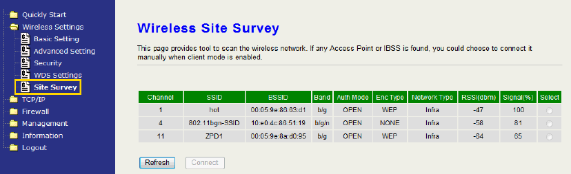
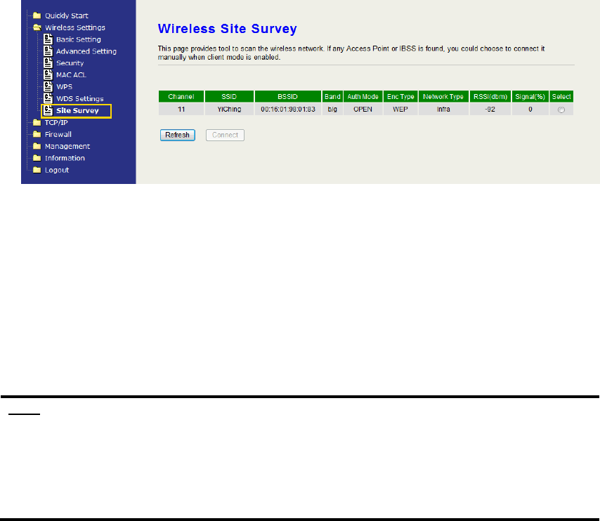
Site Survey
In the Site Survey page, you can scan the SSID in the neighborhood in all
modes including AP, Client, WDS, AP+WDS mode. You can see the usage of
the Wi-Fi Channel, and then you can setup a different channel for the device
accordingly to reduce the overlapping. Please refer to the basic setting section
to setup channel. Click “Refresh” to rescan it. In client mode, the Radio button
“Select” can be checked to connect. Check the one you want to connect and
then click “Connect” to connect.
Configuring as WLAN Client Adapter
This device can be configured as a wireless Ethernet adapter. In this mode,
the device can connect to the other wireless stations (Ad-Hoc network type)
or Access Point (Infrastructure network type) and you don’t need to install
any driver.
Quick start to configure
Step 1. In “Basic Settings” page, change the Mode to “Client” mode. And
key in the SSID of the AP you want to connect then press “Apply
Changes” button to apply the change.
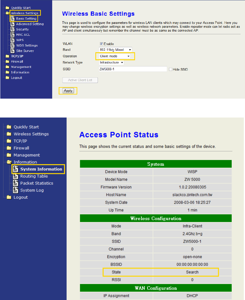
26
Step 2. Check the state of connection in “Status” web page.
The alternative way to configure as following:
Step 1. In “Wireless Site Survey” page, select one of the SSIDs you want
to connect and then press “Connect” button to establish the link.
27
Step 2. If the linking is established successfully. It will show the message
“Connect successfully”. Then press “OK”.
Step 3. Then you can check the linking information in “Status” page.
Note :
If the available network requires authentication and data encryption, you need
to setup the authentication and encryption before step1 and all the settings
must be as same as the Access Point or Station. About the detail
authentication and data encryption settings, please refer the security section.
Authentication Type
In client mode, the device also supports two Authentication Types “Open
system” and “Shared Key”. Although the default setting is “Auto”, not every
Access Points can support “Auto” mode. If the authentication type on the
Access Point is knew by user, we suggest to set the authentication type as
same as the Access Point.
Data Encryption
In client mode, the device supports WEP and WPA Personal/Enterprise
except WPA2 mixed mode data encryption. About the detail data encryption
settings, please refer the security section.
Ch 3. Configuring WDS
Wireless Distribution System (WDS) uses wireless media to communicate
with the other devices, like the Ethernet does. This function allows one or
more remote LANs connect with the local LAN. To do this, you must set
these devices in the same channel and set MAC address of other devices
28
you want to communicate with in the WDS AP List and then enable the
WDS.
When you decide to use the WDS to extend your WLAN, please refer the
following instructions for configuration.
z The bridging devices by WDS must use the same radio channel.
z When the WDS function is enabled, all wireless stations can’t connect
the device.
z If your network topology has a loop, you need to enable the 802.1d
Spanning Tree function.
z You don’t need to add all MAC address of devices existed in your
network to WDS AP List. WDS AP List only needs to specify the MAC
address of devices you need to directly connect to.
z The bandwidth of device is limited, to add more bridging devices will
split the more bandwidth to every bridging device.
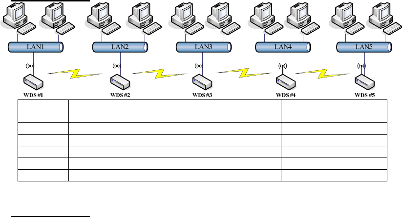
WDS network topology
In this section, we will demonstrate the WDS network topologies and WDS
AP List configuration. You can setup the four kinds of network topologies:
namely bus, star, ring and mesh.
In this case, there are five devices with WDS enabled: WDS1, WDS2,
WDS3, WDS4 and WDS5.
Bus topology:
Device Entries of WDS AP List Spanning Tree
Protocol Required
WDS1 The MAC Address of WDS2 No
WDS2 The MAC Addresses of WDS1 and WDS3 No
WDS3 The MAC Addresses of WDS2 and WDS4 No
WDS4 The MAC Addresses of WDS3 and WDS5 No
WDS5 The MAC Address of WDS4 No
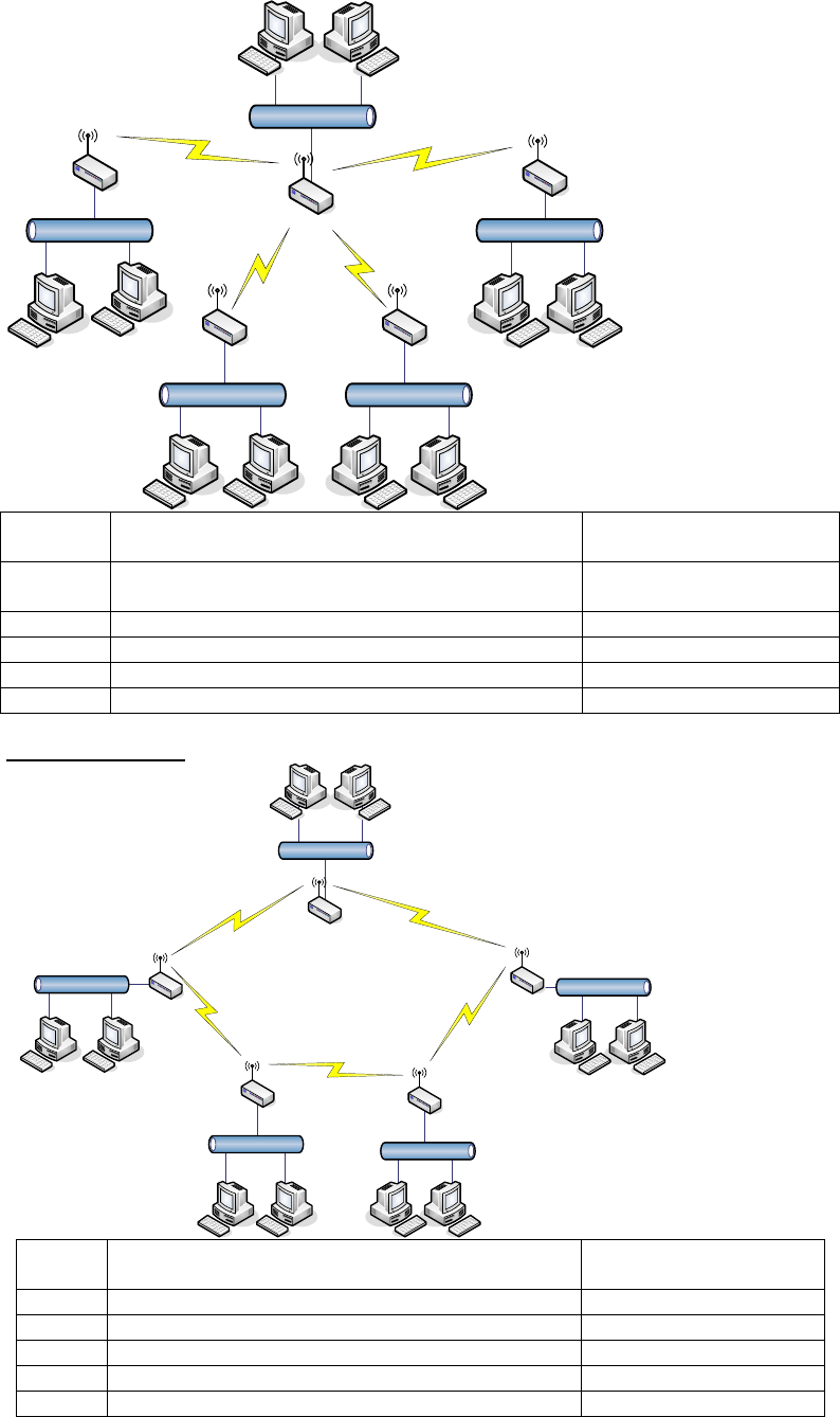
Star topology:
29
LAN3LAN 4
LAN 1
LAN 2LAN 5
WDS #5 WDS #2
WDS #3WDS #4
WDS #1
Device Entries of WDS AP List Spanning Tree
Protocol Required
WDS1 The MAC Addresses of WDS2, WDS3, WDS4
and WDS5
No
WDS2 The MAC Address of WDS1 No
WDS3 The MAC Address of WDS1 No
WDS4 The MAC Address of WDS1 No
WDS5 The MAC Address of WDS1 No
Ring topology:
LAN3
LAN 4
LAN 1
LAN 2
LAN 5
WDS #5 WDS #2
WDS #3
WDS #4
WDS #1
Device Entries of WDS AP List Spanning Tree
Protocol Required
WDS1 The MAC Addresses of WDS2 and WDS5 Yes
WDS2 The MAC Addresses of WDS1 and WDS3 Yes
WDS3 The MAC Addresses of WDS2 and WDS4 Yes
WDS4 The MAC Addresses of WDS3 and WDS5 Yes
WDS5 The MAC Addresses of WDS4 and WDS1 Yes
30
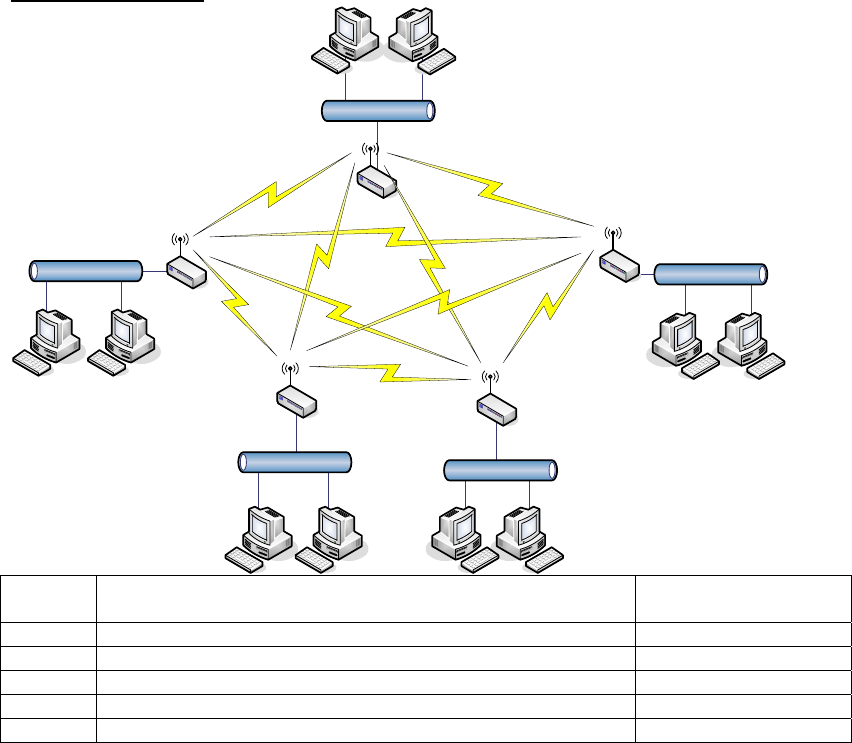
Mesh topology:
LAN3
LAN 4
LAN 1
LAN 2
LAN 5
WDS #5 WDS #2
WDS #3
WDS #4
WDS #1
Device Entries of WDS AP List Spanning Tree
Protocol Required
WDS1 The MAC Addresses of WDS2, WDS3, WDS4 and WDS5 Yes
WDS2 The MAC Addresses of WDS1, WDS3, WDS4 and WDS5 Yes
WDS3 The MAC Addresses of WDS1, WDS2, WDS4 and WDS5 Yes
WDS4 The MAC Addresses of WDS1, WDS2, WDS3 and WDS5 Yes
WDS5 The MAC Addresses of WDS1, WDS2, WDS3 and WDS4 Yes
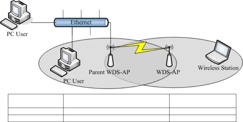
WDS Application
Peer to Peer connection
WDS-AP can be used to increase the coverage area of another device
(Parent WDS-AP). Between the Parent WDS-AP and the WDS-AP, Wireless
Stations can move among the coverage areas of both devices. When you
decide to use the WDS function to connect another WDS-AP, please refer to
the following instructions for configuration.
z In AP mode, enable the WDS function.
z You must set these connected devices with the same radio channel and
SSID.
z Choose “WDS+AP” mode.
z Using the bus or star network topology.
31
Description Entries of WDS AP List Spanning Tree
Protocol Required
Parent WDS-AP The MAC Address of WDS-AP Yes
WDS-AP The MAC Address of Parent WDS-AP Yes
Wireless Bridge
Wireless Bridge can establish a wireless connection between two or more
Wired LANs. When you decide to use the WDS as a Wireless Bridge, please
refer the following instructions for configuration.
z In AP mode, enable the WDS function.
z You must set these connected devices with the same radio channel, but
you may use different SSID.
z Choose “WDS” mode for only wireless backbone extension purpose.
z You can use any network topology, please refer the WDS topology
section.
32
Ch 4. Advanced Configurations
Configuring LAN to WAN Firewall
Filtering function is used to block or permit packets from LAN to WAN. The
device supports three kinds of filter Port Filtering, IP Filtering and MAC
Filtering. All the entries in current filter table are used to restrict or allow
certain types of packets from your local network to through the device. Use
of such filters can be helpful in securing or restricting your local network.
Denied or Allowed list depends on your IP forwarding default policy in Route
page. The IP forwarding default policy is “Accept”.
If you want to block some application from LAN to WAN, you can go to the
“Firewall” page, then “NAT” and select “Drop” for IP Forwarding Default
Policy. Then go to the Port filtering, IP Filtering, MAC Filtering page option to
edit the permit list.
Port Filtering
When you enable the Port Filtering function, you can specify a single port
or port ranges in current filter table. If you select “Accept” for the IP
forwarding default policy, once the source port of outgoing packets match
the port definition or within the port ranges in the table, the firewall will
block those packets form LAN to WAN.
If you select “Drop” for the IP forwarding default policy, once the source
port of outgoing packets match the port definition or within the port ranges
in the table, the firewall will allow those packets form LAN to WAN.
33
IP Filtering
When you enable the IP Filtering function, you can specify local IP
Addresses in current filter table. If you select “Accept” for the IP forwarding
default policy, once the source IP address of outgoing packets match the
IP address definition in the table, the firewall will block those packets form
LAN to WAN.
When you select “Drop” option for default policy, once the source IP
address of outgoing packets match the IP address definition in the table,
the firewall will allow those packets form LAN to WAN.
MAC Filtering
When you enable the MAC Filtering function, you can specify the MAC
Addresses in current filter table. If you select “Accept” for the IP forwarding
default policy, once the source MAC Address of outgoing packets match
the MAC Address definition in the table, the firewall will block those
packets form LAN to WAN.
If you select “Drop” for the IP forwarding default policy, once the source
MAC Address of outgoing packets match the MAC Address definition in
the table, the firewall will allow those packets form LAN to WAN.
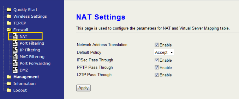
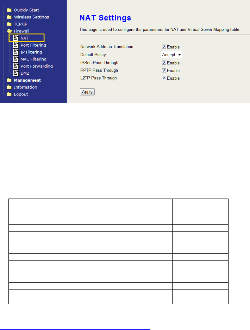
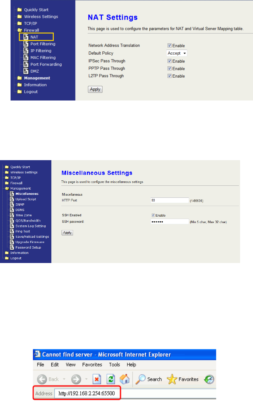
NAT (Network Address Translation)
NAT is the translation between public IP address and private IP address.
While NAT is enabled, you can use port forwarding or DMZ option to redirect
your common network services. If you want to disable NAT, you can go to
Management-Route page to disable it and the functions of DMZ, Port
Forwarding will be disabled.
34
Configuring Port Forwarding (Virtual Server)
This function allows you to automatically redirect common network services
to a specific machine behind the NAT firewall. These settings are only
necessary if you wish to host some sort of server like a web server or mail
server on the private local network behind the device's NAT firewall.
The most often used port numbers are shown in the following table.
About the other well-known ports, please search in
http://www.iana.org/assignments/port-numbers.
Configuring DMZ
A Demilitarized Zone is used to provide Internet services without
sacrificing unauthorized access to its local private network. Typically, the
DMZ host contains devices accessible to Internet traffic, such as Web
(HTTP) servers, FTP servers, SMTP (e-mail) servers and DNS servers.
So that all inbound packets will be redirected to the computer you set. It is
Services Port Number
ECHO 7
FTP (File Transfer Protocol) 21
Telnet 23
SMTP (Simple Mail Transfer Protocol) 25
DNS (Domain Name System) 53
Finger 79
HTTP (Hyper Text Transfer Protocol) 80
POP3 (Post Protocol) 110
NNTP (Network News Transport Protocol) 119
SNMP (Simple Network Management Protocol) 161
SNMP trap 162
SIP (Session Initiation Protocol) 5060
PPTP (Point-to-Point Tunneling Protocol) 1723
35
also useful while you run some applications (ex. Internet game) that use
uncertain incoming ports.
Enable DMZ: Enable the “Enable DMZ”, and then click “Apply Changes” button to
save the changes.
DMZ LAN IP: Input the IP Address of the computer that you want to expose to
Internet.
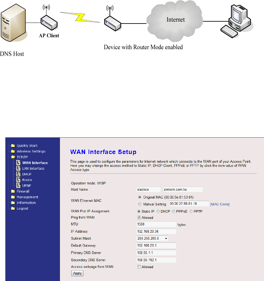
Configuring WAN Interface
The device supports four kinds of IP configuration for WAN interface,
including Static IP, DHCP Client, PPPoE and PPTP. You can select one of
the WAN Access Types depend on your ISP required. The default WAN
Access Type is “Static IP”.
Static IP
You can get the IP configuration data of Static-IP from your ISP. You will
need to fill the fields of IP address, subnet mask, gateway address, and
one of the DNS addresses.
Host Name: Input the host name for the device.
IP Address: The Internet Protocol (IP) address of WAN interface
36
provided by your ISP or MIS. The address will be your
network identifier besides your local network.
Subnet Mask: The number used to identify the IP subnet network,
indicating whether the IP address can be recognized on the
LAN or if it must be reached through a gateway.
Default
Gateway:
The IP address of Default Gateway provided by your ISP or
MIS.
Default Gateway is the intermediate network device that has
knowledge of the network IDs of the other networks in the
Wide Area Network, so it can forward the packets to other
gateways until they are delivered to the one connected to
the specified destination.
Primary &
Secondary DNS:
The IP addresses of DNS provided by your ISP.
DNS (Domain Name Server) is used to map domain names
to IP addresses. DNS maintain central lists of domain
name/IP addresses and map the domain names in your
Internet requests to other servers on the Internet until the
specified web site is found.
Manual Setting
(MAC Clone):
Clone device MAC address to the specify MAC address
required by your ISP
MTU size: Input the MTU size according to the requirement of ISP.
Ping from WAN: Check to allow ping from WAN
Access webpage
from WAN: Check to allow open the configuration page from WAN.
DHCP Client (Dynamic IP)
All IP configuration data besides DNS will obtain from the DHCP server
when DHCP-Client WAN Access Type is selected.
Host Name: Input the host name for the device.
MTU size: Input the MTU size according to the requirement of
ISP.
Set DNS server: The IP addresses of DNS provided by your ISP.
DNS (Domain Name Server) is used to map domain
names to IP addresses. DNS maintain central lists of
domain name/IP addresses and map the domain
names in your Internet requests to other servers on
the Internet until the specified web site is found.
Manual Setting
(MAC Clone):
Clone device MAC address to the specify MAC
address required by your ISP
Ping from WAN: Check to allow ping from WAN.
Access webpage
from WAN: Check to allow open the configuration page from
WAN.
37
PPPoE
When the PPPoE (Point to Point Protocol over Ethernet) WAN Access
Type is selected, you must fill the fields of User Name, Password provided
by your ISP. The IP configuration will be done when the device
successfully authenticates with your ISP.
Host Name: Input the host name for the device.
MTU size: Input the MTU size according to the requirement of ISP.
PPPoE User
Name: The account provided by your ISP.
PPPoE
Password:
The password for your account.
Max Idle
Time:
The number of inactivity minutes to disconnect from
ISP. This setting is only available when “Connect on
Demand” connection type is selected.
MTU Size: Maximum Transmission Unit, 1492 is the default
setting; you may need to change the MTU for optimal
performance with your specific ISP.
Set DNS
server:
The IP addresses of DNS provided by your ISP.
DNS (Domain Name Server) is used to map domain
names to IP addresses. DNS maintain central lists of
domain name/IP addresses and map the domain
names in your Internet requests to other servers on the
Internet until the specified web site is found.
Manual
Setting (MAC
Clone):
Clone device MAC address to the specify MAC address
required by your ISP.
Ping from
WAN: Check to allow ping from WAN
Access
webpage
from WAN:
Check to allow open the configuration page from WAN.
PPTP
Point to Point Tunneling Protocol (PPTP) is a service that applies to
connections in Europe only.
Host Name Input the host name for the device.
IP Address: The Internet Protocol (IP) address of WAN interface
provided by your ISP or MIS. The address will be your
network identifier besides your local network.
38
Subnet Mask: The number used to identify the IP subnet network,
indicating whether the IP address can be recognized
on the LAN or if it must be reached through a
gateway.
Server IP Address:
(Default Gateway)
The IP address of PPTP server.
User Name: The account provided by your ISP
Password: The password of your account
MTU Size: Maximum Transmission Unit, 1412 is the default
setting, you may need to change the MTU for optimal
performance with your specific ISP.
Manually set DNS: The IP addresses of DNS provided by your ISP.
DNS (Domain Name Server) is used to map domain
names to IP addresses. DNS maintain central lists of
domain name/IP addresses and map the domain
names in your Internet requests to other servers on
the Internet until the specified web site is found.
Manual Setting
(MAC Clone): Clone device MAC address to the specify MAC
address required by your ISP.
Ping from WAN: Check to allow ping from WAN
Access webpage
from WAN: Check to allow open the configuration page from
WAN.
Configuring DHCP Server
1. To use the DHCP server inside the device, please make sure there is no
other DHCP server already existing in the same network as the device.
2. Enable the DHCP Server option and assign the client range of IP
addresses as following page.
3. When the DHCP server is enabled and also the device router mode is
enabled then the default gateway for all the DHCP client hosts will set to
the IP address of device.
DHCP Server Check to enable DHCP Server
Assigned IP
Address Input the beginning and the ending IP Address of the
DHCP range.
Assigned Gateway Input the gateway of the Assigned IP Address.
DHCP IP Lease
Time Input the lease time for assigned IP Address.
DHCP Static Map Input the reserved IP Address for the certain DHCP
clients.
39
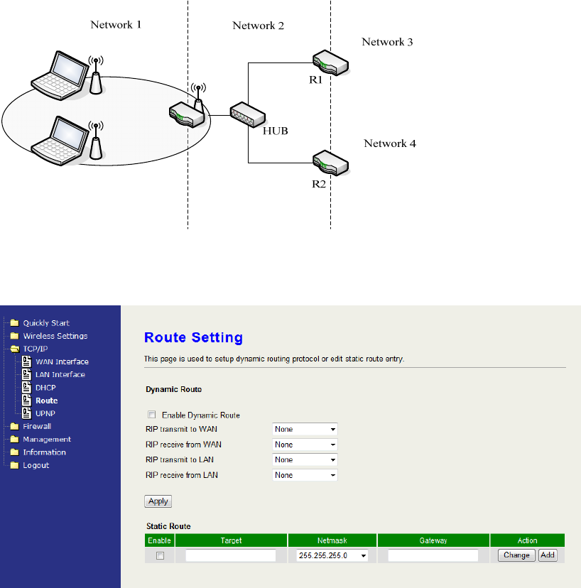
Static Route Setup
User can set the routing information let the Router knows what routing is
correct also it can not learn automatically through other means.
For example, if user wants to link the Network 3 and Network 4 separately from
Network 1 that Routing Table configuration as below:
1. Enable Static Route in Route Setup of TCP/IP page and then enter IP
Address of Network 3、Subnet Mask and IP Address of Router (R1) in
Default Gateway field final click Apply Change button.
2. Enter IP Address of Network 4、Subnet Mask and IP Address of Router (R2)
in Default Gateway field final click Apply Change button.
3. In Static Route Table there have two routings for Network 3 and Network 4
40
Dynamic Route Setup
The Dynamic Route utilizes RIP1/2 to transmit and receive the route
information with other Routers.
1. Enable Dynamic Route and then select RIP 1 、RIP2 or Both to
transmit/receive packets final click Apply Change button.
2. Click Show Route Table button to show Dynamic Route Table.
3. In Dynamic Routing Table there have two routings for Network 3 and
Network 4
UPNP
Check to enable the UPNP setting. The UPNP Map will show.
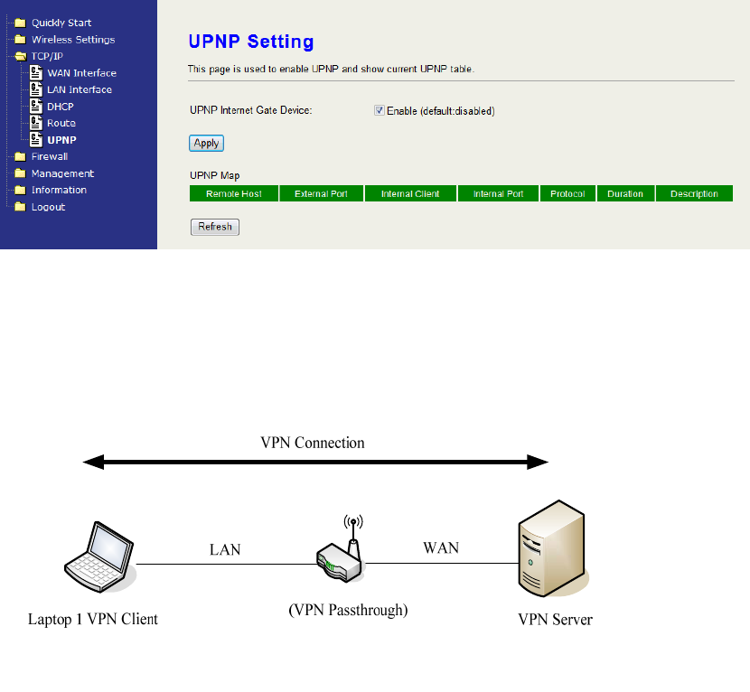
VPN Pass-through
This functionality let the device can Pass-through the VPN packets including
PPTP/ L2TP/IPsec VPN Connection.
1. Check the kind of VPN Pass-through in NAT Page that you want and then
click Apply Changes button.
41
CH5. The Management
Miscellaneous
HTTP Port
The default http port is 80. For security concern, you can change the
device’s http port, to protect this web server from intrusion and attack.
1. Entering the port number you want to change in HTTP PORT field,
then click Apply Changes button.
2. After apply change, you should re-login the web server. Type
http://192.168.2.254:65500/ in URL field.
42
SSH Port
Check to enable SSH login. Input the password for SSH login.
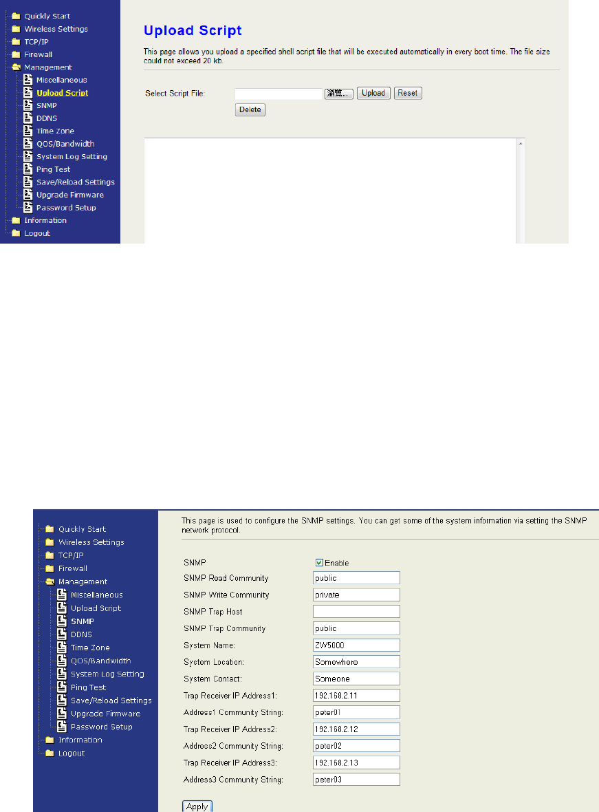
Upload Script
You can upload your private script file or paste your script into the
device.
SNMP
This device is compatible with SNMP v1/v2c and provides standard MIB II.
Currently only the “public” community string is available and the modified
settings by SNMP SET request will be lost after rebooting the device.
1. Enable SNMP and then enter IP Address of SNMP Manager in “Trap
Receiver IP Address” field and Community String in System
Community String field. Finally click Apply Changes button.

43
2. Following Table describes the SNMP configuration parameter
Label Description
SNMP Read Community This string is for SNMP Get-Request for
accessing the device.
SNMP Write Community This string is for SNMP Set-Request for
accessing the device.
SNMP Trap Host Setup the Trap host for sending the SNMP
event.
SNMP Trap Community Setup the string for the trap community.
System Name Type the Name which is the name of
device.
System Location Type the Location which is location of
device
System Contact Type the Name which is person or group
when the device has problem can find
they.
Trap Receiver IP Address Type the IP Address which is address of
SNMP Manager. There are three different
Trap Receiver IP Addresses allowed.
Addresss1 Community
String
This string allows receiving trap from the
device. There are three respective string
for setup.
3. SNMP Traps
Traps Description
coldStart(0) The trap from device after reboot the
device
linkDown(2) The trap is sent when any of the links are
down. See the following table.
linkup(3) The trap is sent when any of the links are
UP. See the following table.
authenticationFailure(4) The trap is sent when the device receiving
gets or sets requirement with wrong
community.
4. Private MIBs
OID Description
1.3.6.1.4.1.99.1 Mode, Operation Mode in device.
1.3.6.1.4.1.99.2 SSID, SSID of the device
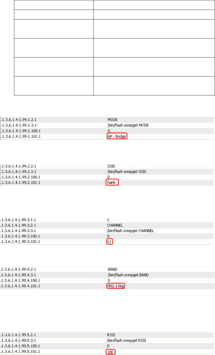
44
1.3.6.1.4.1.99.3 Channel, Channel of the device in WLAN
1.3.6.1.4.1.99.4 Band, 802.11g / 802.11b only
1.3.6.1.4.1.99.5 RSSI, Receive Signal Strength Index
(Support AP and Client RSSI)
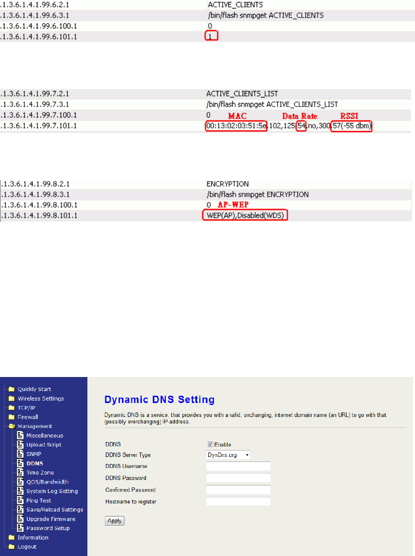
1.3.6.1.4.1.99.6 Active_Clients, The number of associate
clients
1.3.6.1.4.1.99.7 Active_Clients_List, Client’s Information
(MAC Address, Data Rate, RSSI…etc)
1.3.6.1.4.1.99.8 Encryption, Encryption type of device in
Wireless Network
1.3.6.1.4.1.99.1 - Mode
1.3.6.1.4.1.99.2 - SSID
1.3.6.1.4.1.99.3 - Channel
1.3.6.1.4.1.99.4 - Band
1.3.6.1.4.1.99.5 - RSSI
45
1.3.6.1.4.1.99.6 - Active_Clients
1.3.6.1.4.1.99.7 - Active_Clients_List
1.3.6.1.4.1.99.8 - Encryption
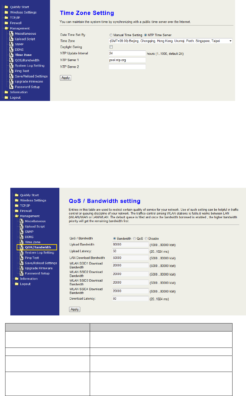
DDNS
If you want to access the device from Internet with the dynamic IP (DHCP,
PPPoE) WAN of the device, you can use the DDNS function. First you go to
the web site of DDNS to register a DDNS account. Then setup the information
in the DDNS page of the device. The device will update the current IP Address
when it changes to DDNS site. Through DDNS service, the user can use the
same URL to connect to the device even the IP Address is changing.
Time Zone
If the device connects to the Internet, it will update the time automatically. If
doesn’t, you can manually setup the time.
46
QoS / Bandwidth setting
You can select one between Bandwidth and QoS. Select “Disable” to disable
this function.
Bandwidth
This functionality can control Bandwidth of Up/Downstream.
Enable Bandwidth Control and then enter Upload Bandwidth, Latency and
Download Bandwidth in the specific field.
Parameter Definition
Label Description
Upload Bandwidth Similar a buffer to limit the Upstream
throughput.
Upload Latency Similar a waiting time the data queuing- time.
LAN Download
Bandwidth
Similar a buffer to limit the Downstream
throughput for LAN.
WLAN SSID1 Download
Bandwidth
Similar a buffer to limit the Downstream
throughput for the WLAN. If multi-SSID is
enabled, there will be respective text field of
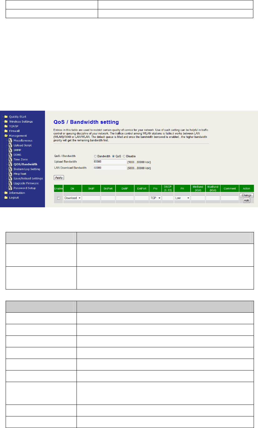
47
download bandwidth for every SSID.
Download Latency Similar a waiting time the data queuing- time.
QoS
QoS allows you to specify some rules, to ensure the quality of service in your
network. Such as use Bandwidth Priority concept to allocate bandwidth. This
function can be helpful in shaping and queuing traffic from LAN (WLAN) to
WAN or LAN to WLAN, but not WLAN to WLAN.
The following table describes the priorities that you can apply to bandwidth.
Option Description
Upload Bandwidth Speed of transmit data that from Ethernet interface
to Wireless interface.
LAN Download
Bandwidth
Speed of transmit data that from LAN to WAN.
QoS Item Description
SrcIP Input the Source IP Address
SrcPort Input the Source Port
DstIP Input the Destination IP Address
DstPort Input the Destination Port
Pro Select the Protocol between TCP and UDP
DSCP Select the DSCP from 0 to 63
Pri Select the Priority among Low, Medium, High and
Highest.
MinBand (Kbit) Input the minimum bandwidth.
MaxBand (Kbit) Input the maximum bandwidth.
48
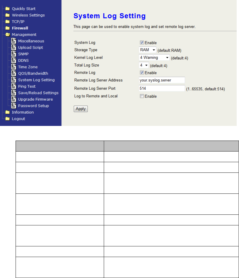
System Log Setting
The device supports the log function. Check the Enable checkbox to setup
the details.
Options Description
System Log Check to enable the log function.
Storage Type Choose RAM or Flash to storage the log.
Kernel Log Level Click the drop-down box to choose one
log level.
Total Log Size Choose whether 4 or 8 KB to storage the
log.
Remote Log Check to enable the remote log.
Remote Log Server
Address
Enter your Remote Log Server Address.
Remote Log Server Port Input the port number
Log to Remote and Local Check save the log into system and
remote server.
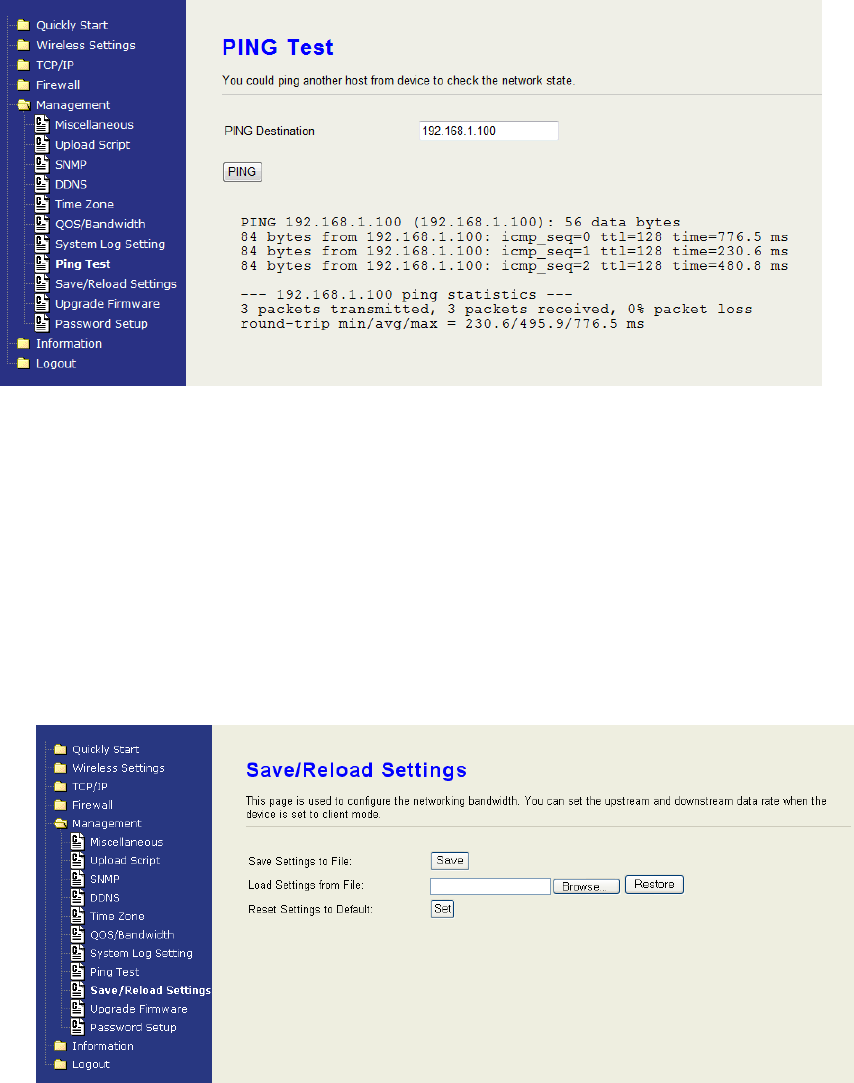
Ping Test
Input the IP Address of any host in the network, and then click PING to ping it.
You will see the ping result as below. You can use this function to check if the
network passes through.
49
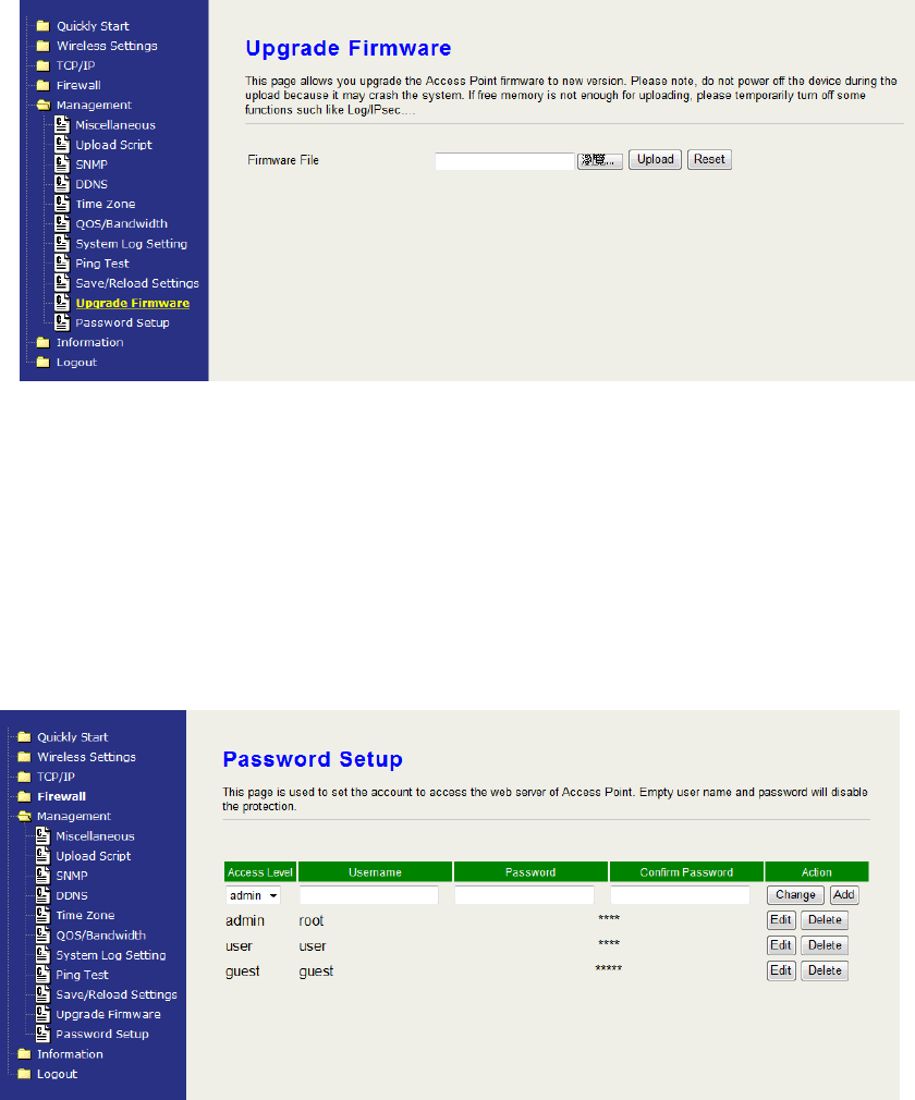
Save/Reload Settings
Reset Setting to Factory Default:
Besides reset through pressing reset button, this device provides the
Web-Browser interface to reset the configuration data. After resetting it,
the current configuration data will be lost and restored to factory default
value.
Saving & Restoring Configuration Data
To save & restore configuration data of device, just assign the target
filename with full path at your local host, then you can backup
configuration data to local host or restore configuration data to the
device.
Upgrade Firmware
The simplest and safest way for upgrading the firmware for an end-user
50
is the Web-Browser upgrading interface. It will check the firmware
checksum and signature, and the wrong firmware won’t be accepted.
After upgrading, the device will reboot and please note that depends on
the version of firmware, the upgrading may cause the device
configuration to be restored to the factory default setting, and the
original configuration data will be lost!
To upgrade firmware, just assign the file name with full path then click
“Upload” button in the following page.
Password Setup
Edit the password for multiple user level login, including admin, user and
guest. Each level has different authority for accessing and configures this
device. Please refer the tables below for the configurable page for every
level.

51
The configurable page for “Admin” level account
Main Category Sub page
All pages are configurable. All pages are configurable.
The configurable page for “Guest” level account
Main Category Sub page
Management Ping Test
Information System Information
Wireless Information
Routing Table
Packet Statics
Logout Logout
The configurable page for “User” level account
Main Category Sub page
Wireless Settings Advanced Settings
Site Survey
TCP/IP UPnP
Management SNMP
DDNS
Time Zone
System Log Setting
Ping Test
Password Setup
Information System Information
Wireless Information
Routing Table
Packet Statics
System Log
The Information
You can view the following information’s including: system information,
wireless information, Routing Table, Packet Statistics and System log in the
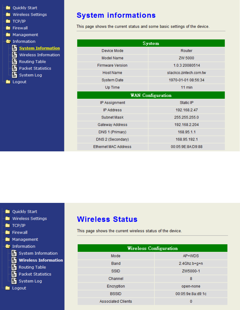
52
category.
System Information
Click to view the information about the device.
Wireless Information
Click to view the wireless information about the device.
Routing Table
Click to view the Routing Table on the device.
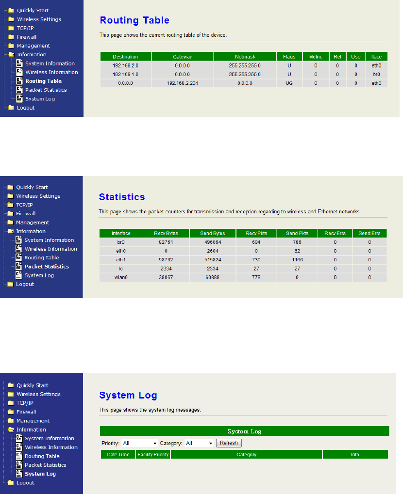
53
Packet Statics
Click to view the packet statics.
System Log
Click to view the log on the device. Click the drop down box of “priority” or
“category” to filter the log. Click “Refresh” to apply the filter.
Logout
Logout
Click the Logout button to log out the current account.
Reboot
The “Guest” account cannot be seen in this page. Click the reboot button to
reboot the device.

54
ZW-5310 Specification
RF SPECIFICATIONS
Frequency range 2.4 ~ 2.484 GHz
5.15~5.26, 5.725~5.825 GHz
802.11g TX power 14dBm ± 1dB @ 54Mbps
802.11b TX power 17dBm ± 1dB @ 11Mbps
802.11a TX power 12dBm ± 1dB @ 54Mbps
802.11n(20MHz)
sensitivity
-70dBm ± 2dB @ 130Mbps
802.11n(40MHz)
sensitivity
-66dBm ± 2dB @ 270Mbps
802.11g RX sensitivity -74dBm ± 2dB @ 54Mbps
802.11b RX sensitivity -89dBm ± 2dB @ 11Mbps
802.11a RX sensitivity -73dBm ± 2dB @ 54Mbps
Data Rate
802.11n (20MHz) 130/117/104/78/65/58/52/39/26/19.5/13/6.5Mbps
802.11n (40MHz) 270/243/216/162/135/121.5/108/81/54/40.5/27/13.5Mbps
802.11 a/g 54 / 48 / 36 / 24 / 18 / 12 / 9 / 6Mbps
802.11 b 11 / 5.5 / 2 / 1Mbps
ANTENNA Connector Reversed Polarity SMA Male X 3
Operating
Environment
Temperature 0~50C
Humidity 10~90% (non-condensing)
LED Indicators WAN(Orange), LAN x 4(Green), WLAN
(Green), Power (Red), WPS (Blue)
Button WPS in the front panel, Reset in the back panel
Ethernet port WAN: 10/100Mbps x1 port, RJ-45, Auto MDI/MDI-X
LAN: 10/100Mbps x4 ports, RJ-45, Auto MDI/MDI-X
Power Consumption 12Vdc +/- 5% ; 1.5A
Standards WLAN: IEEE 802.11 a/b/g, IEEE 802.11 n Draft 2.0,
IEEE 802.11 h
LAN: IEEE 802.3, IEEE 802.3u, IEEE 802.3x, IEEE
802.11d
Operating Mode Wireless Access Point Multi-SSID (Up to 4 SSID)
AP Client (WISP or Bridge mode)
WDS (P-to-P , P-to-MP Bridge)
Security Password Protection
MAC filtering

55
Hidden SSID Broadcast
64 / 128-bit WEP Encryption
WPS Push Button and PIN Code
WPA for 802.1x and WPA-PSK
WPA2 / IEEE 802.11i
Software Feature WLAN: b/g protection, Block WLAN Relay, Tx Burst,
Tx Short Preamble, Packet Aggregation, HT
Operation mode, HT Guard Interval, HT Tx
Aggregate MSDU, MAC ACL, Site Survey.
WAN: MAC Clone, Static IP/DHCP/PPPoE/PPTP,
MTU.
LAN: DNS relay, 802.11d Spanning Tree, UPNP,
DHCP server.
Routing: Dynamic Route (RIP 2), Static Route.
Firewall: NAT, IPSec Pass Through, PPTP Pass
Through, L2TP Pass Through, Port
Fielding IP Fielding, MAC Filtering, Port
Forwarding, DMZ.
Management: configurable http port, SSH, Private
Script, SNMP v2c, DDNS, NTP client,
QoS/Bandwidth, System log, Ping
Test, Upload config file, Firmware
upgrade, Multiple password.