802265 HT NEW BCS Compact Commercial 09.16 V3.01
2016-09-13
: Zip Water 802265 - Ht New Bcs Compact Commercial 09.16 V3.01 802265 - HT NEW BCS Compact Commercial 09.16 v3.01 zipwater.manuals zipwater.hydrotaps zipwater.products zipwater.australia
Open the PDF directly: View PDF ![]() .
.
Page Count: 28
802265 - Sparkling HT- BCS Compact Commercial - Installation Instructions - 09.16 - v3.01 Page 1 of 28
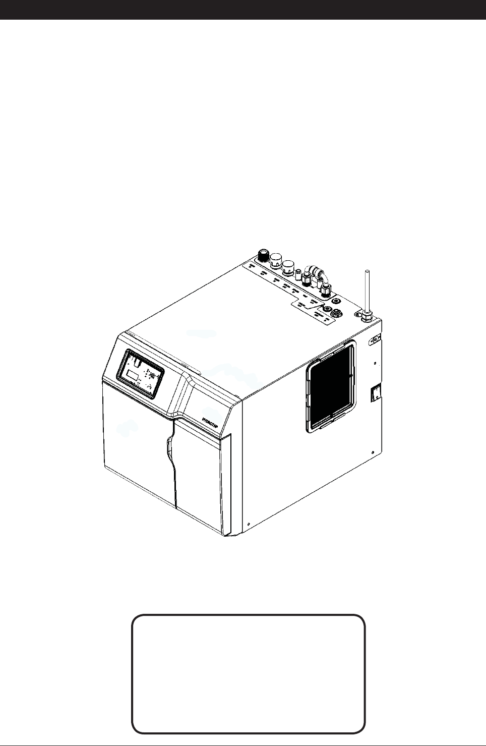
Zip HydroTap
Installation Instructions
Filtered boiling, chilled and Sparkling drinking water for commercial kitchens and tea rooms.
®
Affix Model Number Label
Here
802265
BCS Compact models
Page 2 of 28 802265 - Sparkling HT- BCS Compact Commercial - Installation Instructions - 09.16 - v3.01
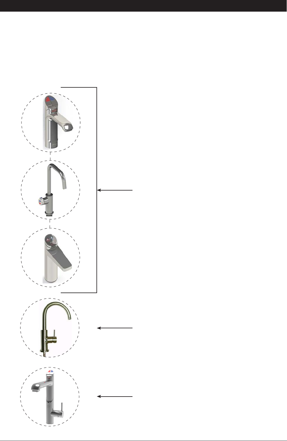
Tap options
The HydroTap applaince series offers a range of interchangeable taps to suit the customer’s needs (See
options below). For ease of installation, it is recommended to fit the tap before installing the undersink unit.
The installation procedure for each of the taps is detailed in a separate tap installation instruction book No.
803341, supplied with the tap.
For all operational features of the HydroTap, please refer to the User manual No.802266.
These three taps are directly compatible with the G4
under bench unit.
The All-In-One Tap is a stand alone tap that may be used
as an alternative to any of the above combinations. The
A-I-O is compatible with the G4 underbench unit.
The Mixer tap is an additional tap that may be used in
conjunction with any one of the three taps shown above,
to create 4-IN-1 models
Tap options:

802265 - Sparkling HT- BCS Compact Commercial - Installation Instructions - 09.16 - v3.01 Page 3 of 28
HydroTap Specifications
Installation check list ....................................................................................................................4
General Product Features ............................................................................................................5
Important Safety Instructions .......................................................................................................6
Warnings and Regulatory Information ..........................................................................................7
Major components and Accessories ............................................................................................8
Technical Specification ................................................................................................................9
Before Installation and site requirements .....................................................................................10
Installation procedure:
STEP 1 -
Fit the tap to the benchtop or sink, before installing the undersink unit.
(Refer to the Tap installation instruction book 803341)
STEP 2 - Check for adequate ventilation
Section 2 - Ventilation
2.1 - Cut out details ..........................................................................................................11-13
STEP 3
- Install the Booster Heater (if required)
Section 3 - Booster heater Installation
3.1 - Booster Heater specifications and Installation ..........................................................14-16
STEP 4 -
Fit the CO2 Gas cylinder
Section 4 - CO2 Cylinder
4.1 - Connect and secure the 2.64kg CO2 gas cylinder ....................................................17-18
4.5 - Leak Test ..................................................................................................................18
STEP 5
- Install the undersink unit
Section 5 - Undersink unit installation
5.1 - Check the external bypass valve setting ...................................................................19
5.2 - Mains water supply hose ..........................................................................................19
5.3 - Model BCS ................................................................................................................20
5.4 - Model BCSHA - AIO Mains .......................................................................................21
5.5 - Model BCSHAV - AIO Vented ...................................................................................22
5.6 - Model 5-IN-1 Vented .................................................................................................23
STEP 6
- Commission the HydroTap
Section 6 - Commissioning
6.1 - CO2 Purge .................................................................................................................24
6.2 - Filter Flush ................................................................................................................24
6.3 - Boiling Calibration .....................................................................................................25
6.4 - Booster activation .....................................................................................................25-26
6.5 - Sensor calibration .....................................................................................................26
6.6 - Check Date and Time settings ..................................................................................26
Trouble Shooting
Trouble Shooting Table ................................................................................................................27
End of life disposal .......................................................................................................................27
Contact details .............................................................................................................................28
Index

Page 4 of 28 802265 - Sparkling HT- BCS Compact Commercial - Installation Instructions - 09.16 - v3.01
Before Installation:
A. Read the instructions and check if there is adequate space to mount all of the components.
B. Note: Not all fittings are supplied with the appliance kit. Isolation valves are not supplied.
C. Check the mains water pressure is between 250 - 700kPa
D. Check the water quality to determine if extra filtration will be required.
NOTE: This product must be fitted to a potable water supply
E. Check the appliance rating plate and ensure correct power is available for the appliance.
F. Check the under counter cupboard supporting the appliance is adequate for
the total weight of the appliance, when full of water.
Before Commissioning:
1. Check the unit has been installed correctly.
2. Check all plumbing fittings have been tightened.
3. Ensure the outlet and vent pipes are positioned to drain correctly.
4. Ensure there is adequate ventilation.
5. Check all tubes from the undersink unit to the tap, have a constant rise and there are no
sags or kinks in the hoses.
6. Check all electrical connections are correct and there are no loose wires.
Commission: (See section 6)
7. Flush the supply line before connecting.
8. Turn on the water and check for leaks.
9. Flush the filters (This commences auto calibration for Boiling models)
10. Activate / enable the Booster (If fitted)
11. Purge the CO2
12. Calibrate the safety sensor (for Boiling models)
13. Where applicable, programme the unit to suit the customer’s requirements.
Installation checklist
802265 - Sparkling HT- BCS Compact Commercial - Installation Instructions - 09.16 - v3.01 Page 5 of 28
Thank you for purchasing a Zip HydroTap. Please read and follow these instructions carefully to ensure safe
and trouble free service. If service is required, please call 1800 638 633
What is the Zip HydroTap ?
The Zip HydroTaps are electronically controlled, filtered, Boiling, Chilled and Sparkling water, drinking
systems for kitchens and tea rooms. The HydroTap units are under bench drinking water appliances with a
dispensing tap mounted on a sink or bench, which may be used for residential or commercial applications.
These units utilise a conventional refrigerant compressor to chill the water and (for BCS) an immersion
heating element to boil the water and all utilise a CO2 gas cylinder to carbonate the chilled water. Depending
on the model, these units will dispense boiling water (factory set to 98°C) chilled water (factory set to 5-10°C)
These units are NOT designed to be used for sanitary fixtures.
The boiling water units are fitted with a tap mounted, child safety lock. In addition, there are various energy
saving options accessible via the main menu. Each boiling unit is equipped with a self-calibrating program
which caters for altitude adjustment. The 2.64kg CO2 bottle is refillable and should be returned to your
nearest HydroTap agency for exchange, whereas the water filter is a disposable item. Both will require
periodic replacement and are covered by a limited OEM warranty.
It is important that the Installation be done safely, correctly and completely, in order to utilise all the benefits
the HydroTap can provide. Each unit can be ordered with the Tap Head Assembly for Disabled use. The
disabled levers are supplied with Braille caps for the visually impaired.
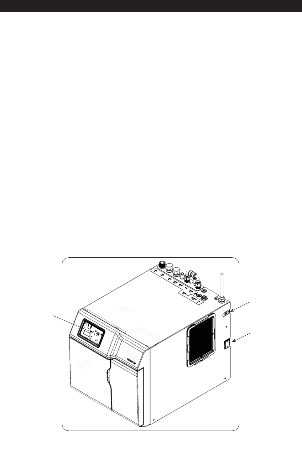
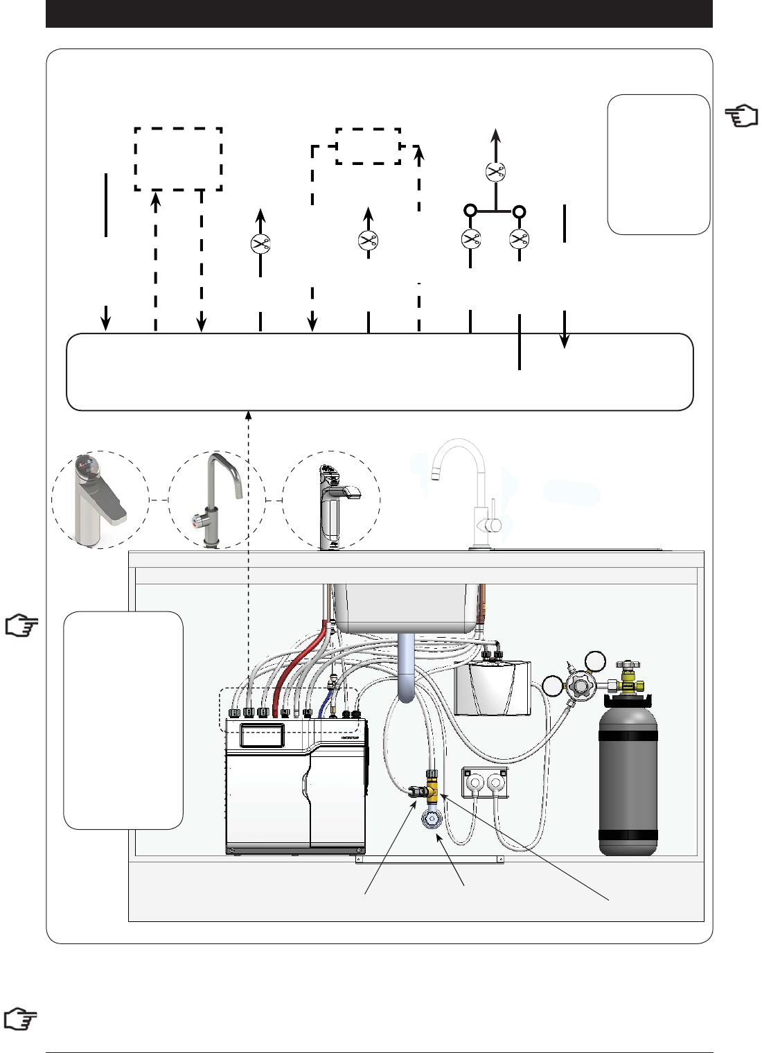
General Product Features
HydroTap BCS Compact
ON-OFF Switch
Command centre
Din plug
(for accessories)

Page 6 of 28 802265 - Sparkling HT- BCS Compact Commercial - Installation Instructions - 09.16 - v3.01
Important Safety Instructions
This manual contains important safety, Installation instructions for the Zip HydroTap G4.
Safety
This appliance is not intended for use by persons (including children) with reduced physical,
sensory or mental capabilities, or lack of experience and knowledge, unless they have been
given supervision or instruction concerning use of the appliance by a person responsible for
their safety. Children should be supervised to ensure that they do not play with the appliance.
For products sold in Europe, this appliance can be used by children aged from 8 years and above and
persons with reduced physical, sensory or mental capabilities or lack of experience and knowledge if they
have been given supervision or instruction concerning use of the appliance in a safe way and understand
the hazards involved. Children shall not play with the appliance. Cleaning and user maintenance shall not be
made by children without supervision.
Refrigerant
The Zip HydroTap unit contains R134A refrigerant under pressure. Maintenance of the refrigeration unit must
be carried out by an accredited service provider or qualified refrigeration technician.
Qualifications
If the power cable is damaged it must be repaired only by a qualified technician. To avoid hazards, all
Installation procedures must be carried out by a suitably qualified tradesperson. The power cable and power
outlet must be in a safe visible position for connection.
Venting
Sometimes steam and / or condensed droplets may discharge through a vent outlet at the tap. If the tap is not
installed using the Font pedestal, ensure the tap body is located so the tap outlet safely dispenses into the
sink bowl area.
Lifting
Take care when lifting the Zip HydroTap unit. Some units may exceed safe lifting limits. If you feel this is
beyond your personal capabilities, please seek assistance with the lift. The weights of the units are marked
on the packaging. Do not lift the unit by the front cover or any connections at the top rear of the unit. Refer to
section 1.2 technical specification for the weight of your product.
Airflow
The ambient temperatures, when installed in a cupboard, must be between 5ºC - 35ºC. Proper air circulation
must be provided. The system will operate satisfactorily only if the recommended air gaps of 50mm on each
side are provided. See section 2 for correct installation details
Altitude
Water boils at varying temperatures at different altitudes. Your HydroTap adjusts for this during startup
calibration and will recalibrate itself on a regular basis.
Frost Protection
If this appliance is located where the ambient air temperature could fall below 5ºC when the heater is not
in use, do not turn off the appliance electrically. This safeguard does not offer the same protection to the
connecting pipework and fittings.ed
Positioning
It is important to ensure the undersink unit is positioned in an accessible area close to the floor level. The unit
must have it’s base mounted in a horizontal position with all inlets and outlets facing up. The Tap must be
located above the undersink unit. See page 12 for details.

802265 - Sparkling HT- BCS Compact Commercial - Installation Instructions - 09.16 - v3.01 Page 7 of 28
Important Safety Instructions
WARNINGS
1.
The Zip HydroTap unit must be earthed. The resistance of the earth
connection from each exposed metal part must be less than 1 ohm.
2.
All Installation and service work must be completed by trained and
suitably qualified Tradespeople. Faulty operation due to unqualified
persons working on this product, or any other Zip product may void
warranty coverage.
3.
All Plumbing must comply with AS/NZS3500.
4.
All Electrical must comply with AS/NZS3000
5.
All Plumbing and Electrical connections must be made in accordance
with local regulations.
6.
This HydroTap product is rated for 230V 50Hz AC operation.
7.
Undersink units must never be located near, or cleaned with water jets.
8.
Zip HydroTaps are not to be exposed to the elements of nature
9.
Due to the process of continuous improvement, Zip Heaters reserves
the right to change details mentioned in this manual, without notice.
2.64 Kg CO
2
Cylinder Warnings:
•
Pressurised container.
•
Protect from sunlight.
•
Contains gas under pressure, may explode if heated.
•
Do not expose to temperatures exceeding 50˚C.
•
Do not pierce or burn, even after use.
•
Do not expose to naked flame or any incandescent material.
•
Keep out of reach of children.
•
High concentration of gas may cause asphyxiation.
•
Use only in ventilated areas.
•
Store in a location with a volume no less than 50 cubic meters for each
2.64 Kg bottle.
•
Use only in an upright position.
•
This bottle must be used with the approved pressure regulator.
•
Avoid shock.
•
Use according to MSDS. (Material Safety Data Sheet).
Page 8 of 28 802265 - Sparkling HT- BCS Compact Commercial - Installation Instructions - 09.16 - v3.01
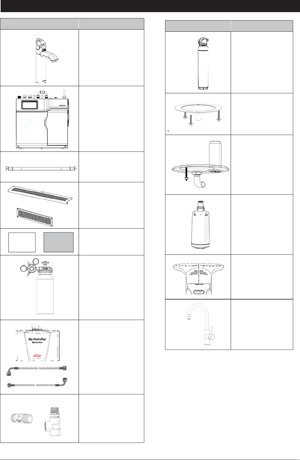
Major components and accessories
Parts supplied Description
1 off 4
HydroTaps
with hoses
(Classic tap shown)
1 off
HydroTap
Undersink Unit with
air and water filters
1 off
Mains water
connection hose
Vent Kit
1 x Inlet vent
1 x Outlet vent
9 x Screws
1 x User manual and
1 x Quick start guide
1 off
CO2 gas cylinder &
regulator assy.
HydroTap Booster
Water System with
connection hoses.
(Model BCSHAV
140/75)
1 x Restrictaflow
valve and Tee piece
for BCSHAV and
select models
Accessories Description
Softener
and head assembly
Font Kit for
Arc & Cube Models
Font Kit for Classic &
Elite Models
Replacement Filter
Disabled lever Kit
5-in-1 upgrage Kit
(Arc mixer shown)
User
Manual
Quick
start guide
802265 - Sparkling HT- BCS Compact Commercial - Installation Instructions - 09.16 - v3.01 Page 9 of 28
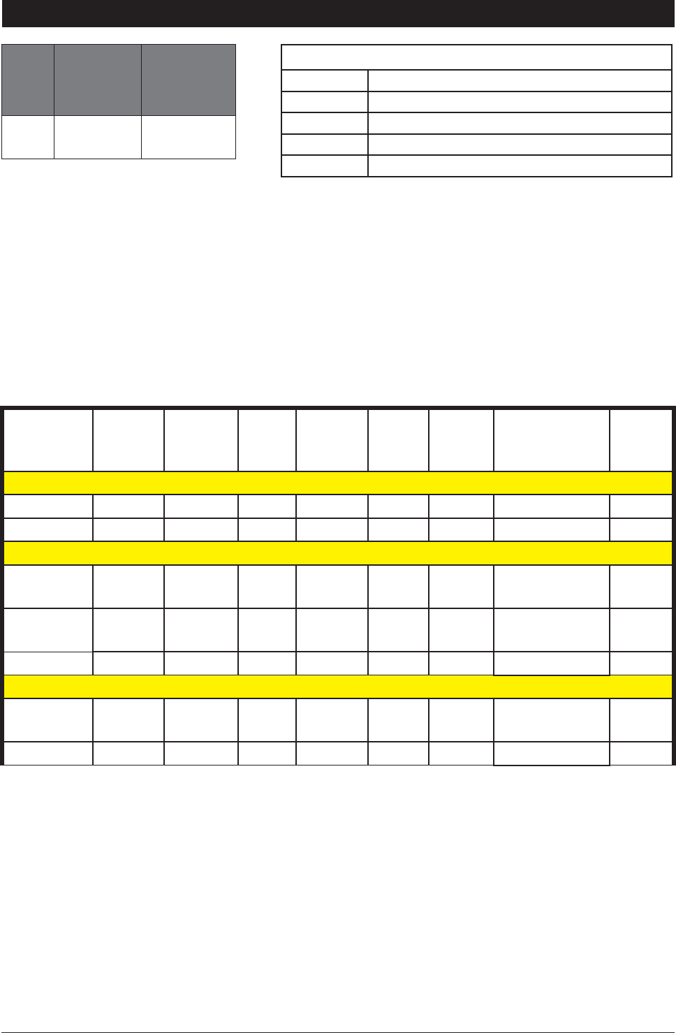
Technical Specifications
Model
Cups of
Boiling
Water per
Hour
Glasses
of Chilled
Water per
Hour
BCS 100 75
Product covered by these instructions:
** Add an extra 4-5 kg when full of water
Capacity
Boiling
(cups)
Capacity
Chilled
(glasses)
Boost
(10A) GPO's
Required Power
Rating
(kW)
Boost
Rating
(kW)
Unit Dimensions
W x D x H (mm) **Dry
Weight
(Kg)
Boiling Chilled Sparkling
BCS100/75 100 75 no 1x10A 2.125 NA 339 x 460 x 335 30
All-In-One
BCSHA-A
100/75 100 75 no 1x10A 2.125 NA 339 x 460 x 335 30
BCSHA-AV
140/75 140 75 no 1x10A 2.125 2.2 339 x 460 x 335 30
5-In-1
BCSHA
100/75 100 75 no 1x10A 2.125 NA 339 x 460 x 335 30
Models
BCS Boiling ; Chilled and Sparkling
BCSHA 5 in One
BCSHA-A All-In-One Mains option
BCSHA-AV All-In-One Vented option
D Disabled lever controls (optional accessory)
Note:
• the Cup measurement =167ml and the Glass measurement = 200ml
•
chilled water will continue to be dispensed after the rated capacity has been used, although this may
be at slightly higher temperature.

Page 10 of 28 802265 - Sparkling HT- BCS Compact Commercial - Installation Instructions - 09.16 - v3.01
Before Installation
Before installing ensure that the following have been provided at the
Installation site:
•
Review all the technical specifications.
•
Ensure the underbench can support the product weight when full of water,
(allow an extra 4-5kg when full. )
•
Sufficient space in the cupboard to install all of the undersink units in accordance with these
Installation Instructions. Refer to technical specification for dimensions. Make allowance for a booster
heater and / or water softener if required. Refer to section 3 & 4, for Installation instructions.
•
For Zip HydroTap 100/175 models, a 220-240Vac, 10A GPO will be required. For Zip HydroTap
140/75 models, two 220-240Vac, 10A GPOs will be required. (One GPO is for the Zip HydroTap and
the other for the Booster heater).
Note
Note: Check all cable and hose lengths against inlet /outlet positions before pro-
ceeding (See section 5 for general layout).
•
A potable water supply connection with isolating valve inside the cupboard within reach of the braided
hoses and positioned so that the connection point and the stop cock will not be obstructed when the
undersink units are installed.
•
For the mains pressure All-IN-ONE, an external hot and cold water supply will be required.
•
If an external filtration or water softening device is required, then it is important to allow extra space
for these items.
•
A cold water supply with a minimum working pressure of 250kPa and a maximum working pressure
of 700kPa connected via an isolation valve.
•
The fitting of an air flow duct, attached to the right hand side of the unit, requires a rectangular cut
size of 284mm x 45mm, to provide adequate warm air displacement. See section 2.
•
The appliance must be placed with it’s base in a horizontal position.
IMPORTANT!
Do not proceed with the Installation if these requirements are not met.
Special Tools Required:
In addition to normal tools, the following will be required:
For the standard and Mixer taps:
•
35mm diameter sheet metal hole punch for sink tops. (Not supplied)
•
35mm diameter hole saw for timber bench tops. (Not supplied)
•
Nut runner tube spanner (supplied) for fixing tap assembly.
For the All-In-One tap:
•
50mm diameter sheet metal hole punch for sink tops. (Not supplied)
•
50mm diameter hole saw for timber bench tops. (Not supplied)
•
Nut runner tube spanner (supplied) for fixing tap assembly.
802265 - Sparkling HT- BCS Compact Commercial - Installation Instructions - 09.16 - v3.01 Page 11 of 28
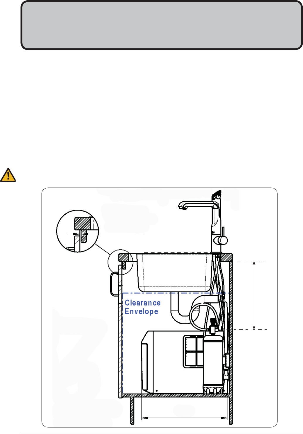
2.1 Ventilation for All Models
Proper air circulation must be provided for all Boiling and Chilled models. The system will operate correctly
only if the recommended air gaps are achieved during Installation. The minimum requirement is for a 50mm air
gap either side and 300mm above of the undersink unit.
It is important that the 4mm door buffers (For all installations ) are fitted to the inside edge of the cupboard
door to allow suficient air circulation inside the cupboard. (See the diagram below).
IMPORTANT:
See section 4 for clearances.
When installing air flow ducts, the following tools will be required:
•
Jigsaw and 12mm Drill
•
Keyhole or Wall Board saw.
Section 2
Ventilation
Min 300mm
460mm
4 min.
Buffer Pad
Clear Gap
Page 12 of 28 802265 - Sparkling HT- BCS Compact Commercial - Installation Instructions - 09.16 - v3.01
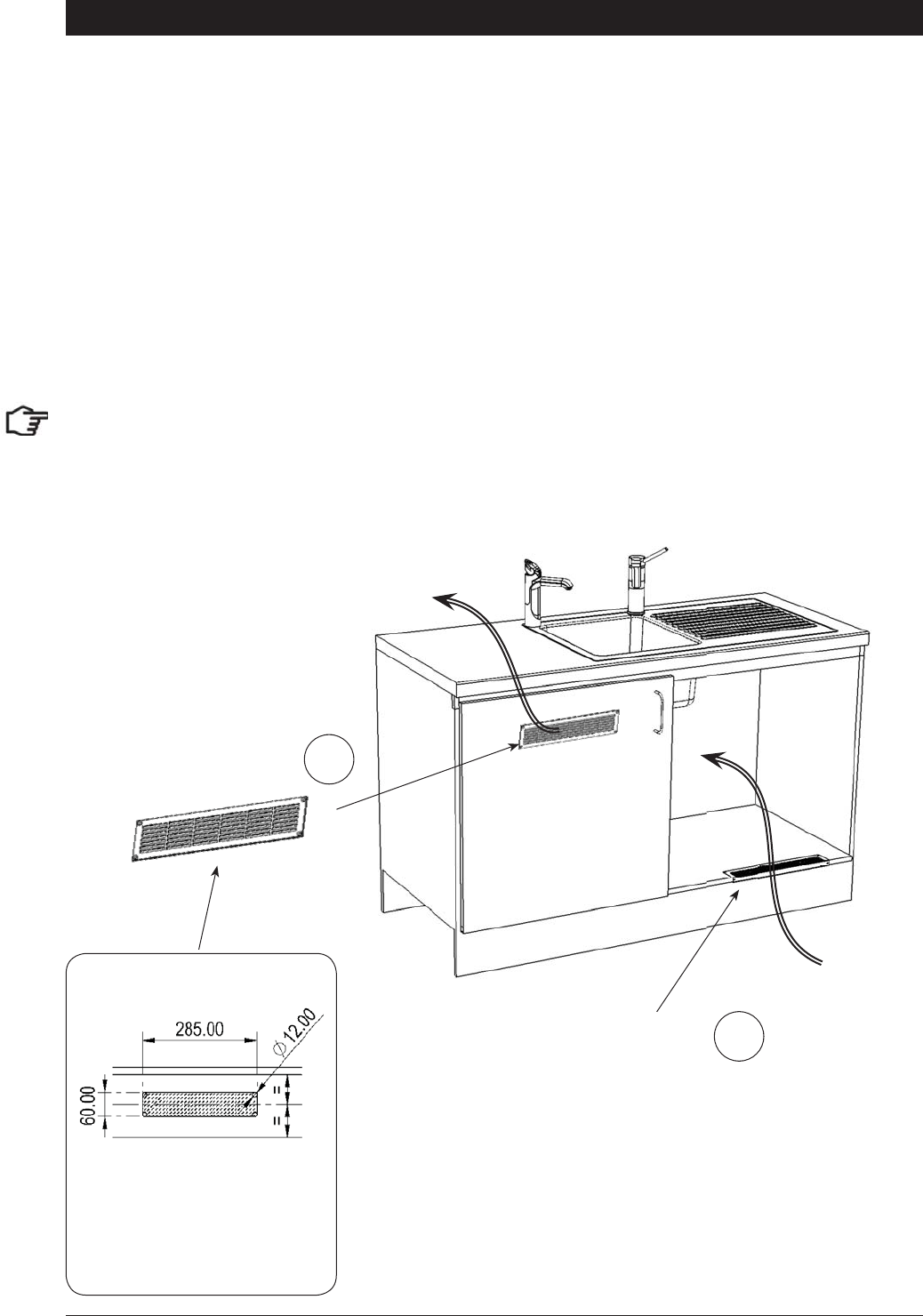
Ventilation
Air inlet vent position
Airflow through the cupboard
B
D
rd
Cool air IN
Warm air
OUT
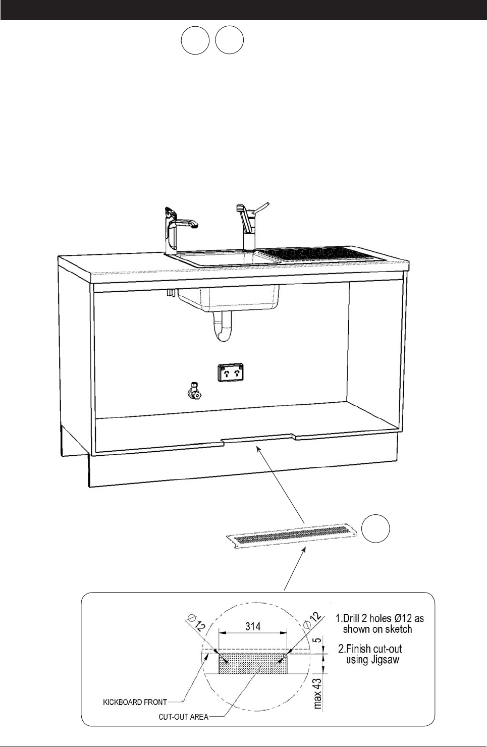
Door outlet vent
1.
Drill four pilot holes
12mm dia.
2.
Finish the cutout using
a jig saw and keyhole
or Wall Board saw
If the air flow, using the silicon door buffers, is insufficient, it will be necessary to fit a standard HydroTap vent
kit, which ensures heat dissipation through natural convection via installed vents.
For high use applications, where the cupboard space temperature is near 35°C, or higher, the inlet vent
(See Item B below) and silicon buffers, need to be fitted. If the airflow is still insufficient to maintain normal
operating temperatures then the inlet vent and door outlet vent (See item D below) will need to be fitted.
Alternatively a fan kit may be installed, using the AUX din plug of the right hand side of the appliance
(Contact your local service centre for availability).
Note: The vent kit has to be installed in a way that allows air to be drawn in from the bottom of the cupboard
and expelled through the top of the cupboard. Therefore placement of the outlet vent should be towards the
top of the door or on the side of the cupboard.
2.2 The following instructions are critical if there is insufficient cupboard air
circulation.
Cutout details
802265 - Sparkling HT- BCS Compact Commercial - Installation Instructions - 09.16 - v3.01 Page 13 of 28
Typical Cut out procedure for
B
Ventilation
Cutout deatils
Air inlet vent
1.
Mark out and cut the air inlet and door outlet holes as shown
2.
Ensure the air inlet vent and air outlet vent are positioned at opposite ends
of the same cupboard space.
3.
Fit the inlet vent, as shown and secure with 5 screws
4.
Fit the outlet vent, as shown in the hottest part (top) of the cupboard and
secure with 4 screws
BD
Page 14 of 28 802265 - Sparkling HT- BCS Compact Commercial - Installation Instructions - 09.16 - v3.01
Booster Specifications:
Rating Unit
Nominal Power Rating 2.2 kW
Nominal Current 10 A
Electric Supply 50Hz AC 230 V
Elect fl ex and plug (black) - 1 meter length (with 90º Aus-
tralian plug) 10 A
Fixed Flow Rate 1.2 L/min
Minimum water pressure 200 kPa
Section 3
Booster Heater
Mount base
Horizontally
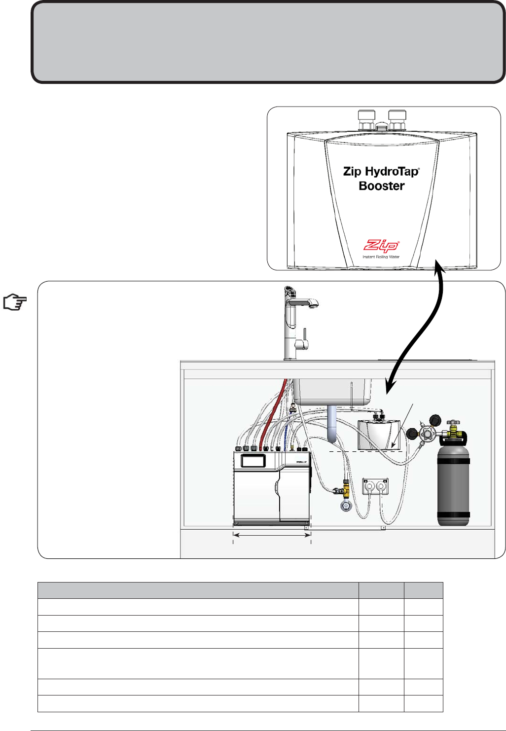
3.1 Product Description
The boost unit is a compact electronically
controlled auxillary water heater. It is intended
to provide pre heating of water before it enters
the Zip HydroTap G4 boiling tank. The Booster
is supplied with the BCSHAV model. However,
it may be later installed, as an accessory for the
BCS model, to increase its delivery.
339 mm
Note1: water connection
:Blue marking - water in
:Red marking - water out.
The braided hoses cannot be
lengthened.
Note2: The electrical cable
length is 1.0 metre.
Note3: Position the Booster
within reach of the fixed hose
lengths, keeping the Booster
as close as possible to the
undersink unit inlet/ outlet
fittings.
Note4: Ensure the Booster
heater is mounted in an
upright position (as shown)
with a horizontal base
802265 - Sparkling HT- BCS Compact Commercial - Installation Instructions - 09.16 - v3.01 Page 15 of 28
Booster Installation
3.2 Installation Procedure
Site requirements
•
Appliance must only be installed in a frost-free area. Never expose appliance to frost.
•
The Appliance is designed for wall mounted Installation and must to be installed with water connectors
facing upwards.
•
The appliance complies with protection class IP 25.
•
The 400mm braided hoses supplied with the unit cannot be lengthened.
•
The 90° elbow hose ends, should be fitted to the inlet and outlet connections on top of the Booster.
•
The hot water outlet hose must be thermally insulated with the insulation provided.
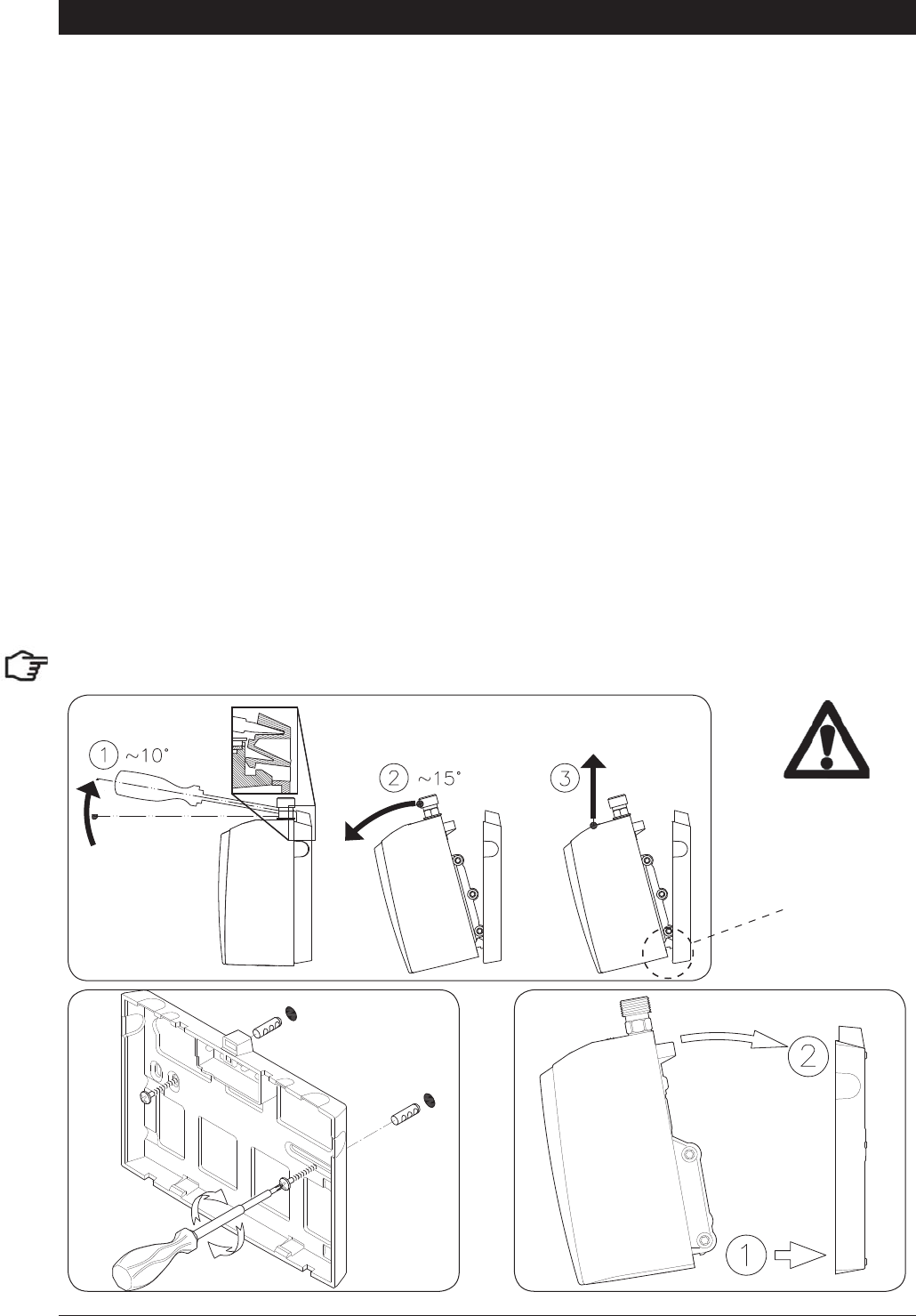
Tilt Forward Lift UP
Release
NOTE: Remove the backing plate for wall mounting
3.3 To Remove / Install the appliance
1.
Insert a flat head screwdriver all the way into the lock.
2.
Gently angle the screwdriver upwards by approximately 10° as shown in the image below.
3.
Pull the appliance forwards by approximately 15° as shown.
4.
Carefully pull the appliance upwards to complete the removal process. Taking care not to break the
lower clips.
5.
To install; Place the appliance on the wall bracket and snap into position (See installation below).
Take care
not to break
the lower
clips when
removing or
installing the
Booster
Installation
Page 16 of 28 802265 - Sparkling HT- BCS Compact Commercial - Installation Instructions - 09.16 - v3.01
NOTE1: This appliance is intended for use with the Zip HydroTap under sink unit.
NOTE2: Water connections must be pointing vertically upwards.
NOTE3: The booster unit should be installed as close as possible to the Zip
HydroTap Unit as the 400mm connection hoses cannot be lengthened.
Booster System
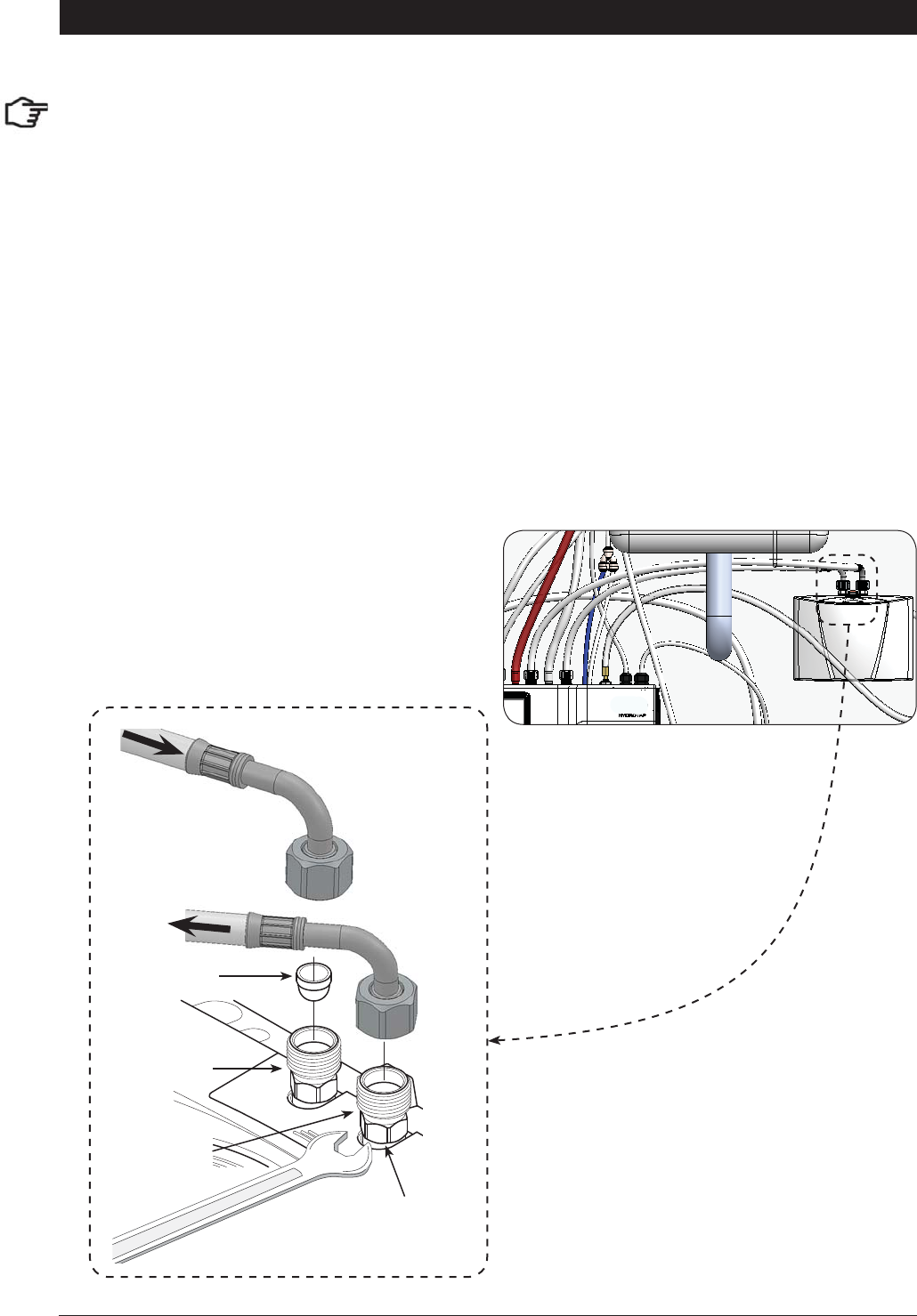
3.4 Braided hose connection
s
1.
The cold water inlet (blue) and hot water outlet (red) are marked on the rating plate. Connect the
braided hoses from the ‘Bypass Out’ fitting to the water inlet of the booster unit (Marked Blue) and
from the outlet of the booster unit (Marked Red) to the ‘Bypass IN’ fitting on the Zip HydroTap unit.
Avoid exerting any mechanical pressure on the appliance. This can be achieved by applying a spanner
on the flats of the inlet and outlet connections when tightening the braided hose connectors. Do not
overtighten ! Tighten the braided hoses by hand, then turn an additional 90° - 180° with a spanner
2.
Once the water connections have been made, check for any leaks and rectify as necessary.
Hot Water
Connection
(outlet, G1/2”)
Strainer
Cold Water
Connection
(inlet, G1/2”)
Hold the hexagon while
tightening the braided
hose fittings
Braided Hoses
Typical Installation

802265 - Sparkling HT- BCS Compact Commercial - Installation Instructions - 09.16 - v3.01 Page 17 of 28
Section 4 - CO2 Cylinder
STORAGE WARNING:
A CO2 gas cylinder of 2.640kg must be installed in an open plan area or in an enclosed room, with a volume
no less than 50m3. If more than 1 gas cylinder containing CO2 is present within the same location, the
recommended ventilated area should be in proportion to the number of gas cylinders stored in that location.
A ventilated area is a non-enclosed area which could include the kitchen, living room etc.
See gas bottle and MSDS sheet for a complete list of warnings. (See: www.zipindustries.com)
4.1 Secure the cylinder cradle
After marking out the cradle location, secure it to a suitable wall, within 1 metre of the unit. Make sure the gas
bottle, regulator and cradle assembly can comfortably fit, with sufficient clearances, before securing the cradle
inside the cupboard. Due to regulatory requirements the gas bottle must be stored securely and in an upright
position. Secure the bottle with the hook-and-loop straps provided.
4.2 Connect the regulator:
After removing all packing material, fit the regulator to the gas bottle as shown in the diagrams. Ensure the
plastic seal is fitted securely inside the large chrome nut, before attaching to the gas bottle. If the plastic seal
is not an easy fit over the spigot, soak it in hot water, before re-applying. Do not force the seal to fit.
Turn the regulator OFF by rotating the regulator knob, all the way out, in an anti-clockwise direction.
NOTE: Two plastic seals are supplied with a new regulator. Only one is required, the other is supplied as
a spare part.
4.3 Connect the gas hose:
Connect the braided gas hose to the top of the underbench unit via the John Guest fitting marked ‘Gas IN’
Then connect the threaded end to the regulator (Do not lose the small sealing olive). When commissioning,
first, turn the regulator, grey knob, all the way out (anticlockwise). Then turn the gas ON by rotating the black
knob on top of the cylinder, anti-clockwise. Finally, adjust the outlet pressure by rotating the grey regulator
knob in a clockwise direction, to between 2.7- 3.0 bar (green zone)
NOTE:
The arrow should sit in the green zone of the regulator gauge; it should not fall in the red or yellow
sections.
4.4 Test for gas leaks:
When commissioning, use soapy water to perform a leak test. Apply the soapy water to the gas connections
using a sponge or brush. If any bubbles appear and grow, there is a gas leak at the connection. Clean away
the soapy residue and tighten or refit the leaking connection. Make sure the gas is turned off when tightening
or refitting the leaking connection.
Fit the gas bottle into the cradle and secure with the Hook-and-loop strap. Ensure the bottle is in an upright
position.
NOTE:
Care must be taken when working with high pressure carbon dioxide, and in no cases should the
normal operating pressure of between 2.7- 3.0 bar be exceeded.
Page 18 of 28 802265 - Sparkling HT- BCS Compact Commercial - Installation Instructions - 09.16 - v3.01
After replacing a bottle or after making a gas connection, perform a Leak Test:
Stage1:
1.
Turn the gas OFF
2.
Using soapy water applied with a sponge, or with a brush, cover all of the gas joints with a liberal
amount of suds.
Stage 2:
1.
Turn ON the gas
2.
Adjust the pressure to between 2.7- 3.0 bar
3.
Inspect the joint for leaks
4.
If any bubbles appear, the joint will need to
be resealed.
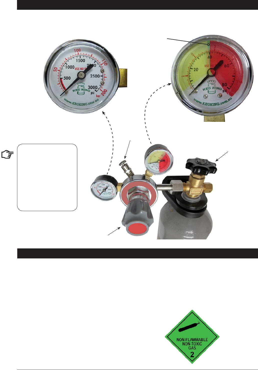
CO2 Regulator
4.5 - Leak Test
This gauge shows the pressure in the bottle
and indicates when the bottle is empty. Initial
bottle pressure will be 35-40 bar.
This gauge shows the adjustable limit (2.7- 3.0 bar)
required for the HydroTap to function correctly
Pressure regulating knob
ON - OFF knob
Green zone
Relief
valve
NOTE:
be careful not to lose the
small sealing olive in the
end of the braided hose.
This olive is necessary to
ensure a gas tight seal
between the braided hose
and the regulator.
802265 - Sparkling HT- BCS Compact Commercial - Installation Instructions - 09.16 - v3.01 Page 19 of 28
If an external filter is installed, select position B
%
5RWDWH
RQO\
Check to determine
which filter bypass
position you need
for your product.
NOTE:
Before you install a unit, determine whether a water softener or an external filter is required.
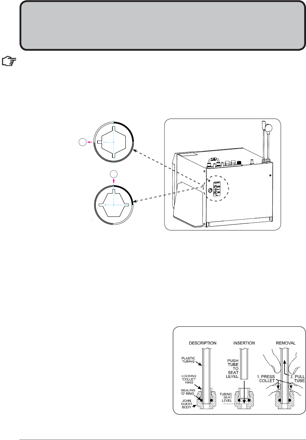
5.1 External Bypass Valve
The diverter bypass valve allows the user to choose to have the boiling feed water bypass the internal filter
and only be filtered by the external filtration. This diverter valve is located at the rear panel of the Zip HydroTap
undersink unit on the filter door side, see the image below.
Section 5
Undersink Unit Installation
If no external fi lter is installed, select position A
$
5RWDWH
RQO\
John Guest fittings (Insertion and removal)
Be careful when cutting the poly tube so that there are no rough edges and that the tube is not distorted.
1.
Use a sharp knife to ensure the tube has a clean,
straight edge. Do not cut at an angle.
2.
Remove any swarf or unwanted material.
3.
Push the tube into the John Guest fitting making
sure all connections to the John Guest fittings are
pushed in past the “O”ring to full depth, at least
15-16mm.
4.
Check for a good joint by pulling back on the tube.
If the tube comes out, of the fitting, repeat the
above step.
5.
To remove the tube, press the collet into the fitting and at the same time pull back on the tube.
5.2 Hose and tube fitting. (Do not overtighten)
•
Remove all caps from the top of the undersink unit (except the mixer caps)
•
Only remove the mixer caps if a mixer tap is to be fitted.
•
Fit the foam insulation to the Blue and to the White tubes after trimming them to length
•
Install the mains water braided hoses to the undersink unit before locating the unit in place.
Page 20 of 28 802265 - Sparkling HT- BCS Compact Commercial - Installation Instructions - 09.16 - v3.01
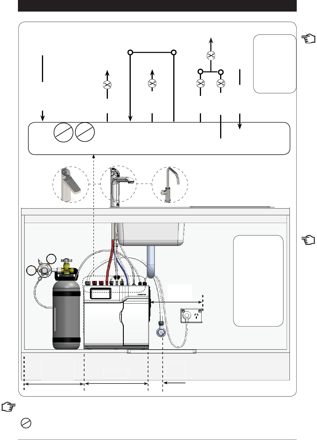
5.3 Model BCS 100/75
Installation Instructions
: Not required for standard BCS HydroTap models.
339mm
Max.
1000mm
Max.
500mm
RED
CLEAR
BLUE
BRAIDED
BRAIDED
POWER
CORD
USB
CHILLED
OUTLET
MAINS
IN MIXER
OUT MIXER
IN BOILING
OUT BYPASS
IN VENT BYPASS
OUT
SPARKLING
OUTLET
CO2
IN
WHITE
Note:
Note:
All
All
silicon tubes
silicon tubes
must be cut to
must be cut to
size. They must
size. They must
have a constant
have a constant
fall back to the
fall back to the
unit.
unit.
Note:
- Mains hose
length is 750mm
- Plug and Cord
length is 1800mm
Position the under
sink unit close
to the outlet tap,
within reach of
the hose and cord
lengths supplied
Note:
The tube lengths are matched to the pumps performance and therefore CANNOT be lengthened
Min.
50 mm side
Clearance
802265 - Sparkling HT- BCS Compact Commercial - Installation Instructions - 09.16 - v3.01 Page 21 of 28
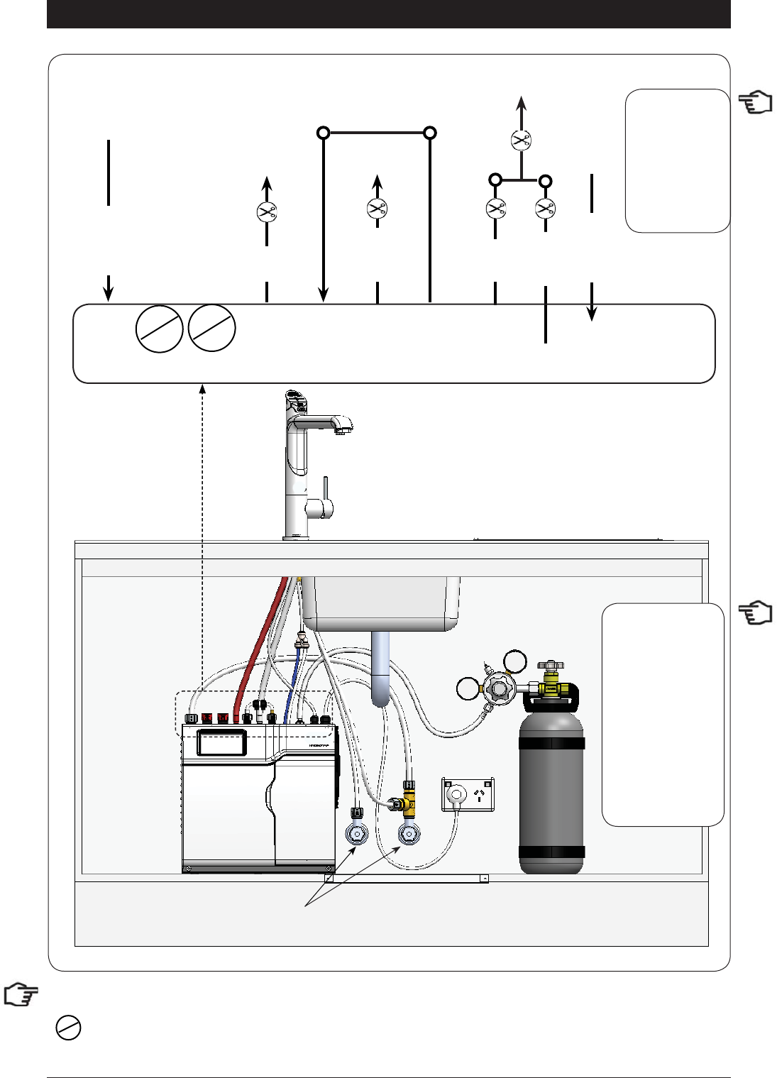
Installation Instructions
: Not required for standard BCSHA HydroTap models
5.4 Model BCSHA 100/75 All-In-One (Mains)
External HOT and COLD
isolation valves
(Not Supplied)
Note:
- Mains hose
length is 750mm
- Plug and Cord
length is 1800mm
Position the under
sink unit close
to the outlet tap,
within reach of
the hose and cord
lengths supplied
Note:
The tube lengths are matched to the pumps performance and therefore CANNOT be lengthened
RED
CLEAR
BLUE
BRAIDED
BRAIDED
POWER
CORD
USB
CHILLED
OUTLET
MAINS
IN MIXER
OUT MIXER
IN BOILING
OUT BYPASS
IN VENT BYPASS
OUT
SPARKLING
OUTLET
CO2
IN
WHITE
Note:
Note:
All
All
silicon tubes
silicon tubes
must be cut to
must be cut to
size. They must
size. They must
have a constant
have a constant
fall back to the
fall back to the
unit.
unit.
Page 22 of 28 802265 - Sparkling HT- BCS Compact Commercial - Installation Instructions - 09.16 - v3.01
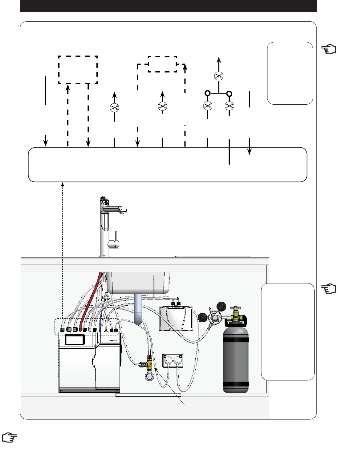
Installation Instructions
Note: to activate the filter, flush at least 10L of water through the filter before connecting to a Booster heater.
Tee piece
(Supplied)
5.5 Model BCSHAV 140/74 All-In-One (Vented)
Booster
BRAIDED
BRAIDED
HydroTap
Mixer
Connections
RED
CLEAR
BRAIDED
POWER
CORD
USB
MAINS
IN MIXER
OUT MIXER
IN BOILING
OUT BYPASS
IN VENT BYPASS
OUT
CHILLED
OUTLET
SPARKLING
OUTLET
CO2
IN
Note:
Note:
All
All
silicon tubes
silicon tubes
must be cut to
must be cut to
size. They must
size. They must
have a constant
have a constant
fall back to the
fall back to the
unit.
unit.
Note:
- Mains hose
length is 750mm
- Plug and Cord
length is 1800mm
Position the under
sink unit close
to the outlet tap,
within reach of
the hose and cord
lengths supplied
Note:
The tube lengths are matched to the pumps performance and therefore CANNOT be lengthened
BLUE
BRAIDED
WHITE
802265 - Sparkling HT- BCS Compact Commercial - Installation Instructions - 09.16 - v3.01 Page 23 of 28
Installation Instructions
5.6 Model BCSHA 140/75 HydroTap 5-In-1 Vented
COLD isolation valve
(not supplied)
Restrictafl ow valve
(Supplied)
Tee piece
(Supplied)
Booster
BRAIDED
BRAIDED
HydroTap
Mixer
Connections
RED
CLEAR
BRAIDED
POWER
CORD
USB
MAINS
IN MIXER
OUT MIXER
IN BOILING
OUT BYPASS
IN VENT BYPASS
OUT CHILLED
OUTLET
SPARKLING
OUTLET
CO2
IN
Note:
Note:
All
All
silicon tubes
silicon tubes
must be cut to
must be cut to
size. They must
size. They must
have a constant
have a constant
fall back to the
fall back to the
unit.
unit.
Note:
- Mains hose
length is 750mm
- Plug and Cord
length is 1800mm
Position the under
sink unit close
to the outlet tap,
within reach of
the hose and cord
lengths supplied
Note:
The tube lengths are matched to the pumps performance and therefore CANNOT be lengthened
BLUE
BRAIDED
WHITE
Page 24 of 28 802265 - Sparkling HT- BCS Compact Commercial - Installation Instructions - 09.16 - v3.01
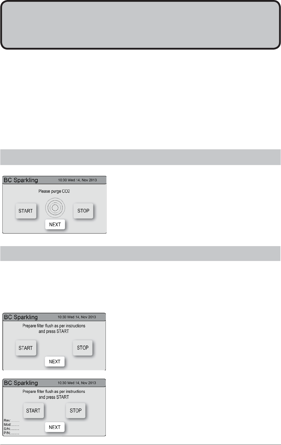
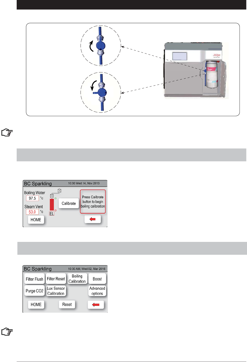
1.
Press [Start] [Stop] buttons to start and stop the filter
flush.
2.
Turn the flush line stop cock ON (See diagram).
3.
Press [Start] and allow at least 10 litres of water to flush
through the filter.
4.
The product details will be displayed in the screen.
5.
Once the filter flush is finished, Turn the stop cock OFF
then press [Stop] to end filter flush mode.
6.
Press [Next] for the Boiling Calibration screen.
Have a 10L bucket or similar container (not supplied) at the ready to hold a quantity of water that will be
ejected while the Filter Flush Mode is in operation. Open the filter access door on the front of the HydroTap
and the filter cartridge will be exposed. Located to the rear RHS of the cartridge is a flush line, approx 600mm
long and the flush line stop cock. Place the valve end of the flush line into the 10L bucket or container.
6.2 - Filter Flush
Section 6
Commissioning
6.1 - CO2 Purge
1.
Press the [START] button to commence the purging
process.
2.
Purge for 10 seconds and ensure all water has stopped
flowing through the tap. (You will hear the CO2 gas
escaping from the tap).
3.
Press the [Stop] button.
4.
Press [Next] for the filter flush screen
The HydroTap is now ready to be commissioned.
•
Turn ON the water and gas and check for any leaks.
•
Turn the power ON at the GPO and at the side of the undersink unit
•
If fitted, ensure the Booster is turned OFF. (The Booster is commissioned, later, at section 6.4)
•
Familiarise yourself with the operation of the Tap, in preparation for use (See User Guide)
•
Follow the Installation instructions below (and review Section C of the User Guide).
•
Initially you will be prompted to select a language
•
After commissioning, the system may be customised by selecting further options in
Section G - Settings, within the User Guide.
802265 - Sparkling HT- BCS Compact Commercial - Installation Instructions - 09.16 - v3.01 Page 25 of 28
OPEN Position
CLOSED Position
ON
OFF
Stop cock
operation
6.3 - Boiling Calibration (Boiling models)
Commissioning
6.4 - Booster
•
Press the calibration button and the system will
commence the Boiling calibration procedure. This
will take aprox 5-6 minutes.
•
Upon completion, a Booster reminder screen will
appear and allow you to return home by pressing
the [Home] button.
NOTE: failing to make the correct selection for the “Booster”, will affect product performance.
NOTE: For any subsequent fi lter changes or any operational procedures, please refer to the HydroTap user
guide, located inside the fi lter housing access door.
Page 26 of 28 802265 - Sparkling HT- BCS Compact Commercial - Installation Instructions - 09.16 - v3.01
Commissioning
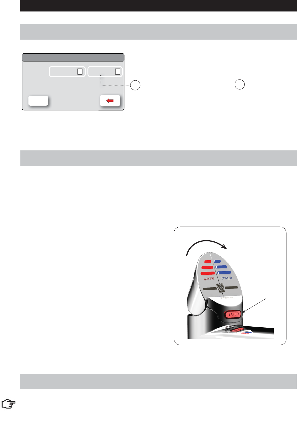
6.5- Safety Sensor Calibration (Classic and All-In-One models)
Disable
Booster
10:30 Wed 14, Nov 2013
BC Sparkling
Zip 1. Press the [MENU] button for main menu.
2. Press the [Install] button.
3. Press the [Booster] button.
4. In the next screen, press button to enable the
Booster.
5. Water must be run through the Booster for a min of 30
seconds, before the heater will activate.
6. Dispense boiling water for 30secs and check the Boost-
er outlet hose is warm when the boiling water tank is
replenishing.
Enable
HOME
To enabled when a Booster unit is installed.
AA
Pull both levers
forward
Safety
sensor
1.
With the unit in Normal operating mode and with
the safety enabled
2.
Turn the power OFF
3.
Pull both tap levers to the forward position
4.
Turn ON the power
5.
The unit will calibrate the safety switch
6.
Return the levers to the neutral position.
7.
To check the calibration, dispense Boiling water,
in normal light conditions with the safety enabled.
Light intensity varies from site to site, therefore it is recommended that a re-calibration be performed at the
time of the installation. All direct natural sun light must be shaded from the HydroTap, during the calibration.
This can be achieved by closing any nearby curtains, blinds, or by shielding the HydroTap with a dark cloth.
NOTE: Depending on your location you may need to re-set the internal clock. See section G of the user
guide to check and if necessary, reset the Date and Time for your time zone.
6.6 - Date and Time check

802265 - Sparkling HT- BCS Compact Commercial - Installation Instructions - 09.16 - v3.01 Page 27 of 28
Trouble Shooting
System Fault
Message Possible Cause Solutions
Power board fault Electrical disruption Check power supply and all fuses
Interface fault Internal fault Call Zip Service
Level board fault Internal fault Call Zip Service
Condenser screen blocked Blocked Air filter Remove blockage / Clean filter / check user guide
Water leak, Isolate mains Water leak Turn off mains water supply / Call for service
Compressor over-run Compressor too Hot Check ventilation
Water supply failed No water Check water supply is turned ON
Hot sensor Open Internal fault Call Zip Service
Hot sensor Closed Internal fault Call Zip Service
Cold sensor Open Internal fault Call Zip Service
Cold sensor Closed Internal fault Call Zip Service
Flood sensor Open Internal fault Call Zip Service
Condenser sensor Closed Internal fault Check Ventilation / Call Zip Service
Condenser sensor Open Internal fault Check ventilation / Call Zip service
Heater fuse / driver fault Internal fault Call Zip Service
Heater driver fault No hot water Call Zip Service
Compressor driver fault No chilled water Call Zip Service
Hot sensor degraded Internal fault Call Zip Service
Condenser overtemp. Blocked air filter Remove blockage / Clean filter / check user guide
A DC Pump is faulty Internal fault Call Zip Service
Steam is too cool Internal fault Call Zip Service
Steam sensor Open Internal fault Call Zip Service
Steam sensor Closed Internal fault Call Zip Service
Over Steamed Internal fault Call Zip Service
Hot tank overfilled Internal fault Call Zip Service
Comp Fuse/Driver Fault Internal fault Call Zip Service
Hot tank under filled Low water pressure Check water supply
Boil dry protection Safety activated Turn OFF / On power to reset
Flash Mem corrupted Internal fault Call Zip Service
Flow Sensor Fault Internal fault Call Zip Service
Call an electrician, a plumber, or Zip for a free call in Australia on 1800-638-633 for assistance, service, spare
parts or enquiries.
In order to help preserve our environment we ask that you dispose of this product correctly. Please contact
your local city council for collection centre details.
End of Life Disposal

Page 28 of 28 802265 - Sparkling HT- BCS Compact Commercial - Installation Instructions - 09.16 - v3.01
Contact Details
The standard cup referred to in this publication is 167 ml (6 fl oz).
The standard glass is 200 ml (7 fl oz).
The terms “Zip” and “HydroTap” are registered trade marks of Zip Heaters
(Aust) Pty Ltd.
Zip products described in this publication are manufactured under one or more
of the following patents: AU675601, AU637412, AU635979, GB0422305,
GB2065848, US4354049, US5103859, US5099825 and SA2006/08043. Other
patents are in force and patent applications are pending.
Head Office
Zip Heaters (Aust) Pty. Ltd.
ABN: 46 000 578 727
67 Allingham Street
Condell Park NSW 2200
Postal: Locked Bag 80
Bankstown 1885 Australia
Website: www.zipwater.com
Facsimile: (02) 9796 3858
Telephone: (02) 9796 3100
Free Call: 1 800 638 633
As Zip policy is one of continuous product improvement, changes to
specifications may be made without prior notice. Images in this booklet have
been modified and may not be true representations of the finished goods. WMKA00099
AS 3498
