86826 WR_FlushMaster Solo Mk2_AU_04 12v1.01 WR Flush Master Mk2 AU
2016-08-17
: Zip Water 86826 - Wr Flushmaster Solo Mk2 Au 86826 - WR_FlushMaster Solo Mk2_AU zipwater.manuals zipwater.washroom zipwater.products zipwater.australia
Open the PDF directly: View PDF ![]() .
.
Page Count: 12
Zip FlushMaster Solo Installation & Maintenance Instructions - 86826 - April 2012 v1.01 Page 1 of 12
Installation and Maintenance Instructions
Zip FlushMaster Solo
®
Water Saver Urinal Flushing System
Keeps Urinals Clean & Reduces Water Wastage
Affix Model Number Label Here
86826

Page 2 of 12 Zip FlushMaster Solo Installation & Maintenance Instructions - 86826 - April 2012 v1.01
You will need one of these accessories (not included in the package).
Table of Contents
Key Features ................................................. 3
Read These Warnings First ............................ 3
Check Your Package ...................................... 3
Installation Procedure .................................... 3
Set Up Water Discharge ................................ 4
Airbreak Installation ....................................... 4
Install Sensor ................................................. 5
Connect Latching Valve Cable ........................ 6
Set Flush Timing ............................................ 7
Maintenance Instructions ............................... 8
Completing Installation .................................. 8
Problem Solving............................................. 9
End of life disposal ........................................ 10
Notes pages .................................................. 11
Contact Details .............................................. 12
99026 Zip FlushMaster Direct Injection Airbreak 1.50 inch BSP/ 38 mm
99025 Zip FlushMaster Direct Injection Airbreak 1.25 inch BSP/ 32 mm
99024 Zip FlushMaster Direct Injection Airbreak 1.00 inch BSP / 25 mm
Accessories
NOTE: You may need the following (not included with this kit)
1) Isolation valve
2) 350 kPa Pressure reduction valve
Zip FlushMaster Solo Installation & Maintenance Instructions - 86826 - April 2012 v1.01 Page 3 of 12
Key Features
One of the world’s most effective, ceiling recessed, urinal flushing systems.
This unit is supplied with a power pack for connection to 220-240 volt AC power.
Smart Demand electronic programming allows for a variable flush cycle to meet
your needs precisely.
Narrow sensitivity beam protects against unwanted flushing operations.
Read These Warnings First
Read all instructions before attempting to install this system.
Never attempt to install this system without reading all instructions.
This unit is designed for indoor use only and should never be installed outdoors or
exposed to the elements of nature. This unit must not be positioned in an area that
may be cleaned by a water jet. This unit must not be cleaned with a water jet.
All plumbing connections must be made in accordance with AS/NZS3500 and
installation with AS/NZS3500.2.
Supply pressure 350kPa - 700kPa ( see recommendations on P7 )
Installation Procedure
1. Set up water discharge with isolating valve, Latching Valve and Airbreak
2. Install sensor
3. Connect latching valve cable
4. Set flush timing
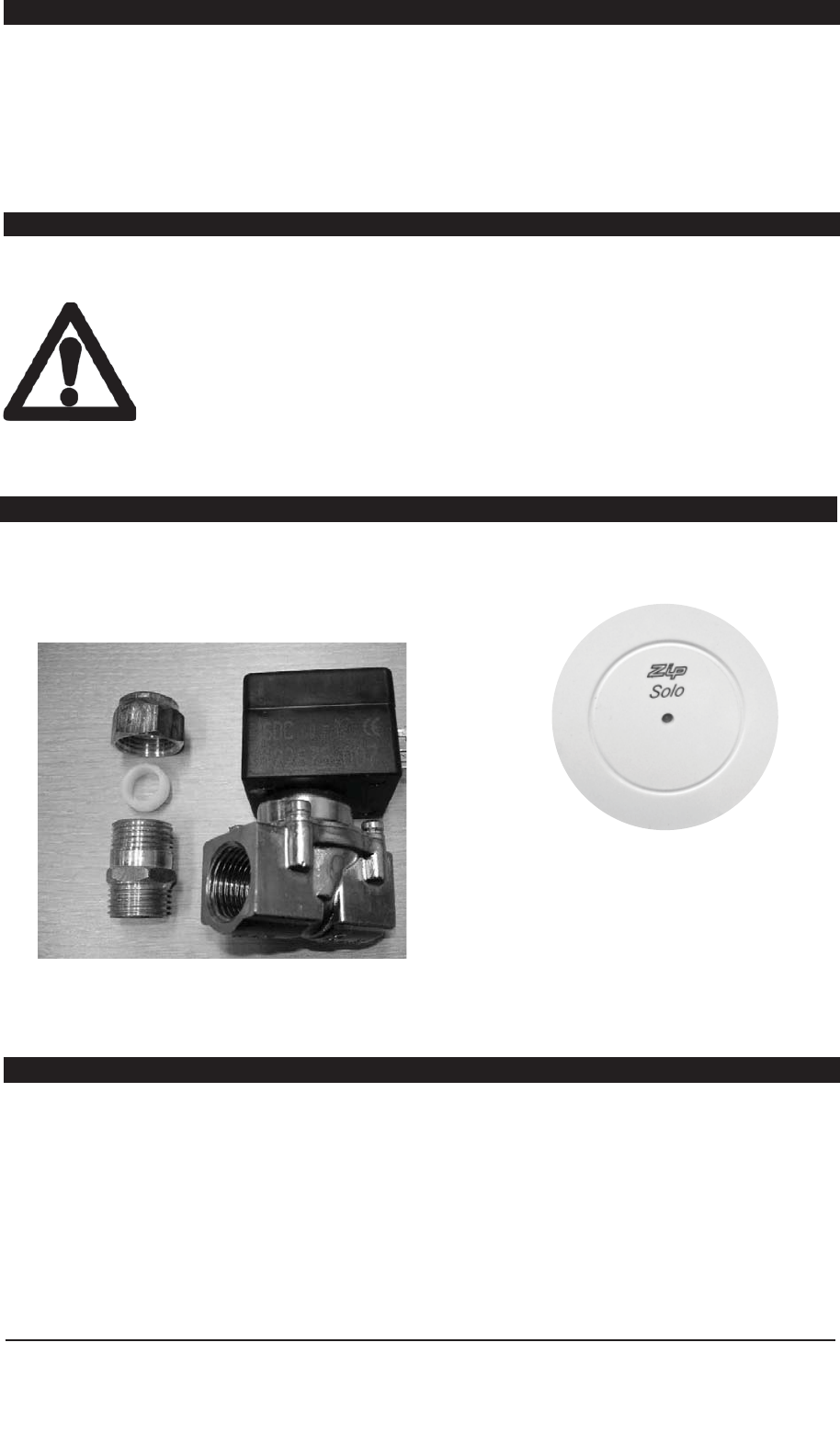
Check Your Package
Zip FlushMaster
Solo package
includes.
Zip FlushMaster Solo WS005 Product Code
42214:
Ceiling recessed Solo sensor complete with
latching valve, power pack and plumbing
Isolation:
An Isolation valve (not supplied) must be fitted, in an accessible position, upstream
of this installation.
Zip FlushMaster Solo Installation & Maintenance Instructions - 86826 - April 2012 v1.01 Page 4 of 12
Airbreak Installation.
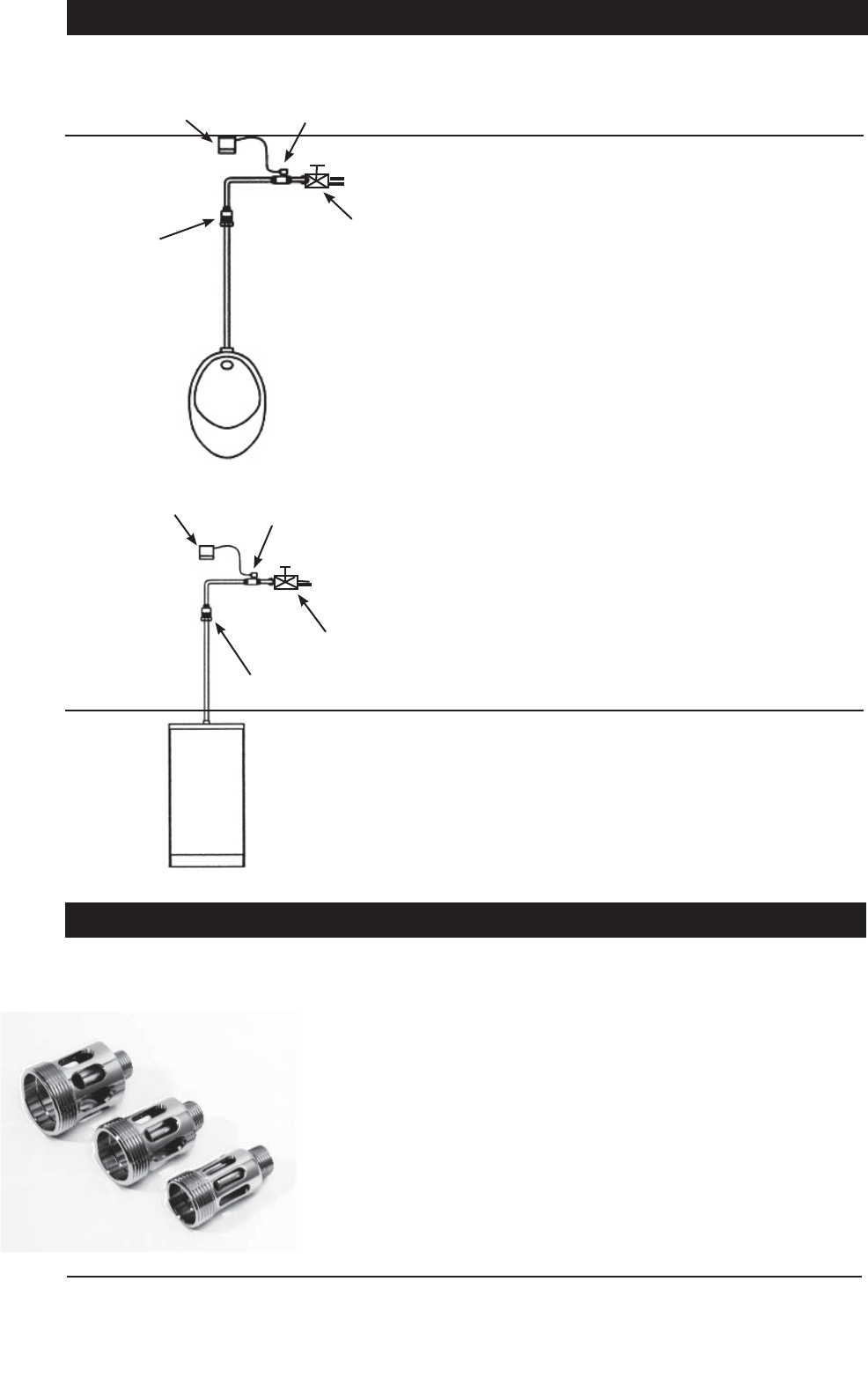
Set Up Water Discharge
Single stall
Single trough
Maximum trough
Width 600 mm
Typical Installation with Direct Injection: Model WS005
- The air break must be fitted in a vertical position. Fitting in a position other
than vertical will result in leakage.
- Fit the air break to the top of the urinal sparge pipe (in place of a cistern),
as shown in the diagram. Locate as high as possible.
- Do not use sealing tape in the air break joints. The fittings in the latching
valve will require the use of sealing tape.
- Supply and install a half-inch pipe from the top of the air break, to the
outlet side of the latching valve.
- Securely fix the piping to the wall as per AS/NZS3500 to prevent possible
tampering and vandalism.
Sensor latching Valve
Isolating Valve
Direct injection
air break
Sensor
latching Valve
Isolating Valve
Direct injection
air break
Zip FlushMaster Solo Installation & Maintenance Instructions - 86826 - April 2012 v1.01 Page 5 of 12
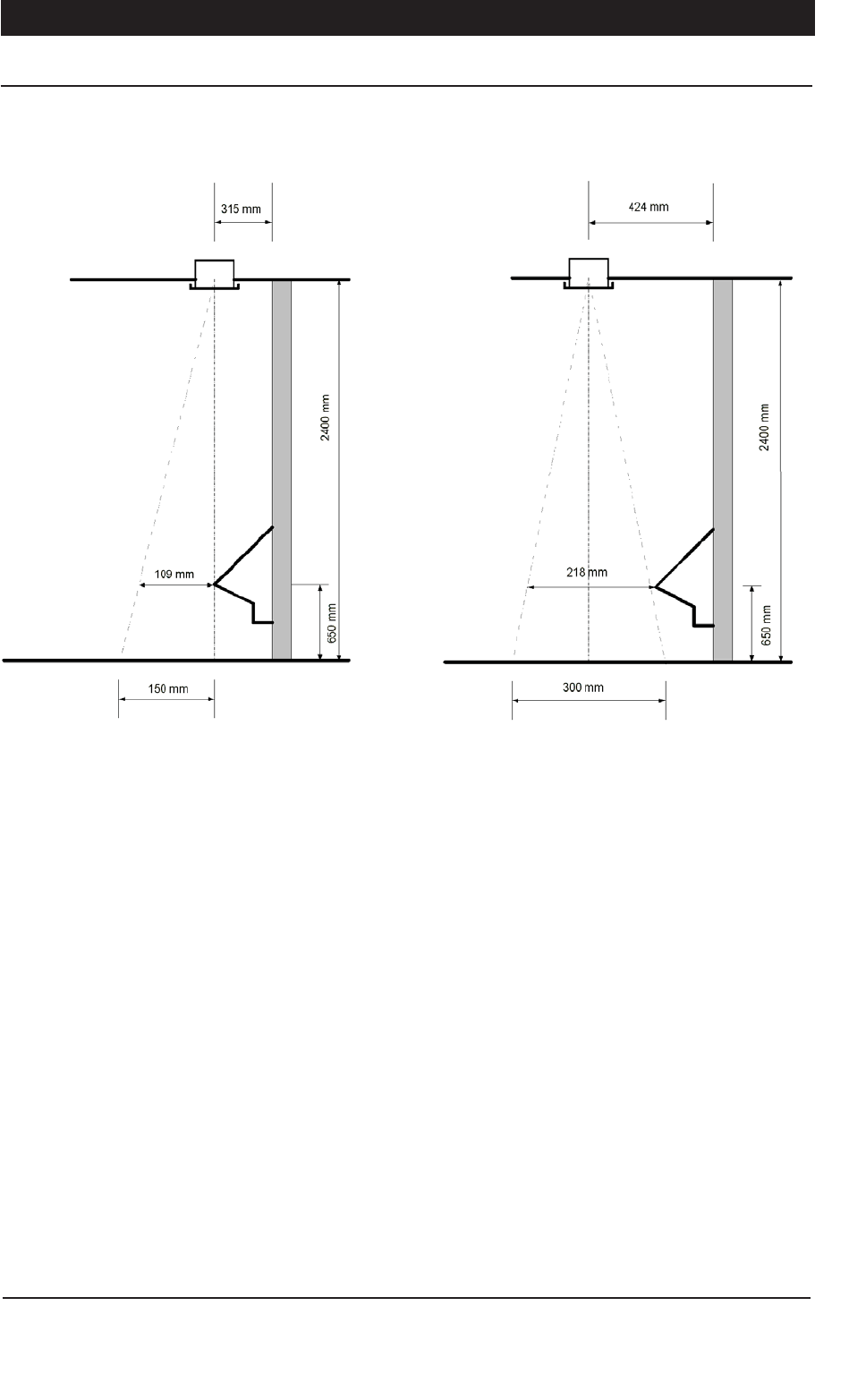
Install Sensor
Position the centre of the ceiling sensor within *109 mm from the front of the
urinal (as shown above).
Typical sensor coverage from a 2400 mm ceiling will be less than 300 mm
in front of the urinal. This is important to avoid false activation of the flushing
program.
To install the ceiling recessed sensor, cut a 64 mm diameter hole in the
ceiling.
Use the inbuilt clips to fasten the sensor housing in place when inserted into
the hole.
If any of the cable connecting the sensor to the latching valve is visible, shield
it with conduit.
Warning. Do not connect the power pack until all plumbing connections are
completed. The power must be connected last as connection activates the
system test mode (see pages 6 & 7).
Typical Installation with Ceiling Recessed Sensor (Model WS005)
Ceiling sensor
Example of
minimum
dimension
Maximum
dimension 424
Ceiling sensor
Example of
maximum
dimension
NOTE: * dimensions may change depending
on type and position of urina.
*
*
*
*
*
*
Page 6 of 12 Zip FlushMaster Solo Installation & Maintenance Instructions - 86826 - April 2012 v1.01
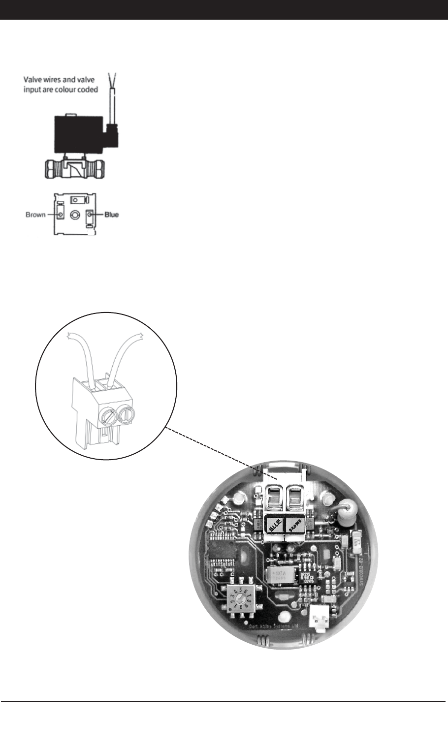
Connect Latching Valve Cable
Run the latching valve cable to the sensor in conduit or within the building wall
and ceiling.
Do not extend the cable as this will affect correct operation.
Locate plug on cable from the latching valve and detach it from circuit board.
The plug should be lifted directly upwards.
Fasten the latching valve cable to the plug on the circuit board by first
removing the plug from the board. Lift plug directly upwards and hold plug so
fixing screws are facing you.
Thread the cable through one of the holes in the the sensor lid,
Secure the brown cable into the right hand screw terminal and tighten.
Secure the blue cable into the left hand screw terminal and tighten.
Push the plug into the socket on the circuit board, positioned so screws face
towards the centre of the board.
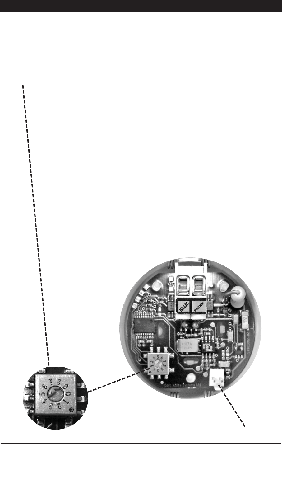
Finally, insert the cable from the power pack into the circuit board inlet socket
.
Once the power is connected, the system can be tested by operating in test
mode.(see page 7)
BLUE
WIRE BROWN
WIRE
21
Zip FlushMaster Solo Installation & Maintenance Instructions - 86826 - April 2012 v1.01 Page 7 of 12
Set Flush Timing
Power connection (from power supply)
Flush time selection (Seconds)
Test mode:
The rotary switch on the board is marked 0 to 9
Position 0 is test mode, where the system will operate automatically for a number of cycles.
Operational mode:
Positions 1 to 9 are flush times in seconds (i.e. Valve opening times).
When first powered the sensor will wait 2.5 minutes and then calibrate it’s surroundings,
after this period it will be ready to detect.
Setting Flush Time:
The beam from the sensor is very narrow so care should be taken when installing so that it
is mounted above the urinal where the user would be.
The sensor will only accept someone as a user if they stand under the beam for 5 seconds
or more, when the user walks away there is a 3 second delay and it will flush for the time
you have set on the rotary switch.
The unit can only be used with the supplied power pack.
Mount the sensor away from lights, hot pipes, ceiling transformers and direct sunlight.
Do not touch components on the board with your fingers.
If the water pressure is greater than 700 kPa then a 350 kPa pressure reducing valve must
be fitted upstream of the latching valve.
Adjust the timing of the flush to ensure an adequate flush, by setting the flush switches on
the sensor board (see diags. below)
When setting the fill time ensure the water does not backup the connection pipe and spill
out of the Air break. If the water is overflowing, or close to overflowing, reduce the fill time,
or pressure. Alternatively, fit a 6 l/m flow restrictor.
Recommended flush settings:
The recommended setting for a single urinal is No.2, when supplied with 350 kPa water
pressure. (see notes on page 11)
NOTE:
Units supplied with
a YELLOW rotary
switch, will not have
a test mode.
For these units
Position 0 will be
non functional
Page 8 of 12 Zip FlushMaster Solo Installation & Maintenance Instructions - 86826 - April 2012 v1.01
Maintenance Instructions
Cleaning
Keep the openings in the face of the sensor clear of dirt.
Never clean the case with strong or abrasive cleaners.
Wipe with a soft cloth, warm water and dish washing liquid.
Never hose or spray any part of the flushing system.
However to avoid the inconvenience associated with any malfunction of the
flushing system, it is recommended that the latching valve diaphragm be
replaced annually.
The power must be turned off at the power point before any form of
maintenance is attempted.
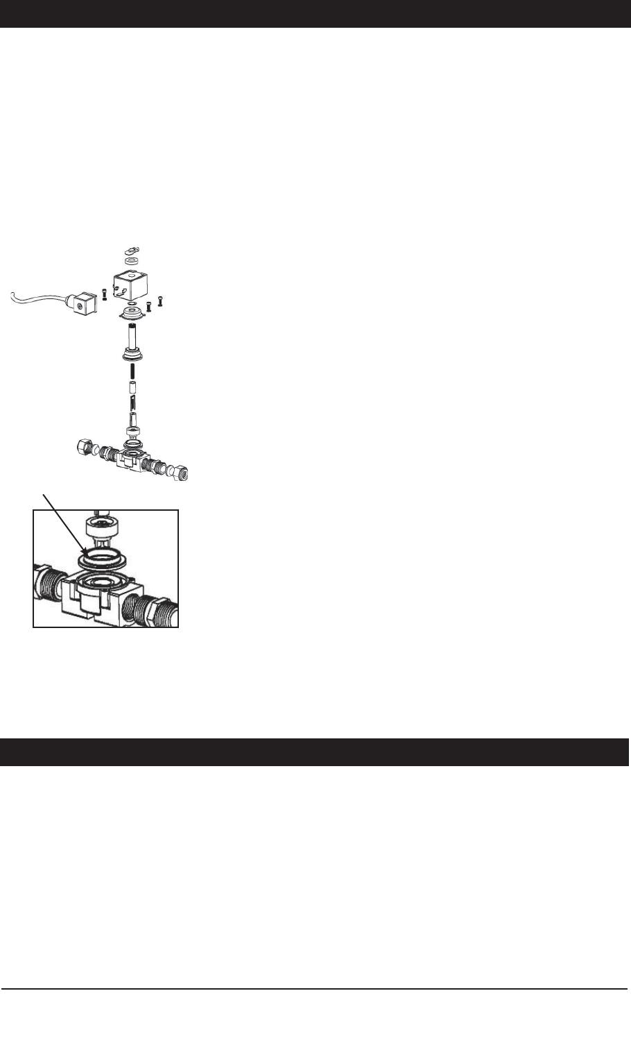
Valve Diaphragm Replacement
Isolate power and water supply.
Remove fixing clip on top of latching valve coil by levering up clip with screw
driver and clicking back until clip releases from shaft.
Lift coil, spring clip and spacer from latching valve shaft.
Carefully undo the 4 screws retaining the valve housing. When the last screw
is about to be released, grip the valve body and top section as it is spring
loaded.
Carefully separate the top section containing the spring and plungers from the
lower body. The diaphragm should now be visible. Lift it out of position.
Remove the centre plastic piece from the rubber diaphragm. Fit the new
diaphragm to the plastic centre. Replace it in the same orientation. The centre
plastic piece and the new diaphragm have two breather holes, try to align
these together when reinstalling a new diaphragm.
Re-assemble in the reverse of above. Note the position of all parts in the
diaphragm for correct assembly. To order quote Zip part number 90279
Diaphragm Kit.
Replacement
rubber for
diaphragm
After setting the desired filling time (p.7), Fit the sensor to the ceiling and wipe
clean the outer surfaces.. Turn on the power and wait for 2.5 minutes. After
this time the system will be ready to detect users
Completing Installation

Zip FlushMaster Solo Installation & Maintenance Instructions - 86826 - April 2012 v1.01 Page 9 of 12
Problem Solving
Symptoms Possible Causes Suggested Action
System does not flush. Water supply turned off.
Latching valve installed backwards.
Latching valve cable damaged or
latching cable unplugged.
Latching valve faulty.
Sensor not activating.
Not sensing user
Check water supply, turn on tap.
Reinstall latching valve correctly.
Check cable and replug into sensor
circuit board.
Replace latching valve.
Check sensor as below.
Must be visible for 5 sec, or more
System flushes too long. Sensor duration time set incorrectly. Reset flush dial to a lower number
See page 7
System flushes for a short period of
time.
Sensor duration time set incorrectly. Reset flush dial to a higher number
See page 7
Sensor not active Wrong ceiling position Reposition sensor.
See page 5
No Power Faulty GPO or household fuse
Faulty power supply
Contact an electrician
Replace power pack
System flushes continually except for
time set as duration ‘on’ period.
Sensor cable wires crossed.
Reversed valve polarity
Uncross latching wire connection.
Change positions 1 &2 on socket (P6)
System continually flushes. Valve diaphragm split
latching valve faulty
Replace diaphragm. See page 8
Replace latching valve
Flushing will not stop. False activation.
Sensor not activating.
Check for sensor vibration.
Check sensor as below.
Sensor not activating. Power turned off.
Damaged sensor
Sensor lens blocked.
Faulty sensor.
Turn on power.
Replace Sensor
Clean sensor lens
Replace sensor.

Page 10 of 12 Zip FlushMaster Solo Installation & Maintenance Instructions - 86826 - April 2012 v1.01
End of life disposal
In order to help preserve our environment we ask that you dispose of this
product correctly. Please contact your local city council for collection centre
details
WELS Ratings:
This system, when tested with a Caroma Leda urinal achieves a 4 Star WELS
rating. In order to maintain the WELS ratings for alternative urinals, the
flushMaster must be set to deliver the correct volume of water as specified by
the urinal manufacturer.

Zip FlushMaster Solo Installation & Maintenance Instructions - 86826 - April 2012 v1.01 Page 11 of 12
NOTES

Zip FlushMaster Solo Installation & Maintenance Instructions - 86826 - April 2012 v1.01 Page 12 of 12
Head Office
Zip Heaters (Aust) Pty. Ltd.
ABN 46 000 578 727
67 Allingham Street
Condell Park NSW 2200
Postal: Locked Bag 80
Bankstown 1885 Australia
Website: www.zipheaters.com
Facsimile: (02) 9796 3858
Telephone: (02) 9796 3100
Free Call: 1 800 638 633
Contact Details
As Zip policy is one of continuous product improvement, changes to specifications may
be made without prior notice. Images in this booklet have been modified and may not be
true representations of the finished goods
