Zonar Systems 80510 80510 User Manual
Zonar Systems Inc 80510
User Manual

REV: 09/15/11
Z-Con™ Hardware Installation Tips
For Professional Installers
Zonar’s equipment will provide years of reliable service if properly installed and maintained. Zonar
equipment is typically installed in heavy vehicle applications and is often subject to extreme temperatures,
dust, dirt, vibration, and shock. Proper installation is the critical first step to equipment longevity and
optimal performance.
This guide is meant to be a general guideline for the professional installer and technician. While we
attempt to point out the most common installation questions and issues; common sense, good
housekeeping procedures, attention to detail, safety adherence, and technical competence of the
professional installer is critical for a successful installation.
Please refer to your specific vehicle manufacturer guidelines for the installation of electrical components
and wiring.
A professional team of Zonar support technicians and engineers are available to answer your installation
questions. Contact Zonar at 1-877-843-3847 or by email at customercare@zonarsystems.com.
Thank you,
Andre J Horochiwsky
Technical Training Manager – Zonar Systems
As Zonar is continuously improving the Product, Zonar may make changes to the Product at any time which may not be reflected in this document.
WOKFLOW
2
Z-Con • V2JE™/TRUCK SIDE BOARD
Introduction ................................................................................................2
System Overview........................................................................................4
V2JE/Truck Board Hardware ......................................................................5
Basic Workflow...........................................................................................6
General Guidelines .....................................................................................6
V2JE Mounting Plate ..................................................................................7
Wiring Guidelines........................................................................................8
V2JE Pin Configuration...............................................................................8
Cables........................................................................................................9
Antenna Installation ..................................................................................11
Non-Typical System Installation ................................................................12
Truck Install Application & Tool..................................................................13
GPS System Check..................................................................................14
System Checklist......................................................................................15
System Specifications ..............................................................................16
Installation Example..................................................................................17
System Installation ..................................................................................18
Troubleshooting...................................................................................19-20
Truck Windshield Configurations .........................................................21-22
Non-Typical System Installation ................................................................23
Warranty & Notices - FCC Compliance.....................................................24
Notes .......................................................................................................25
INTRODUCTION
3
© 2011 Zonar Systems. All Rights Reserved. Products and services protected by one or more
patents:
REV: 09/15/11
SYSTEM OVERVIEW
4
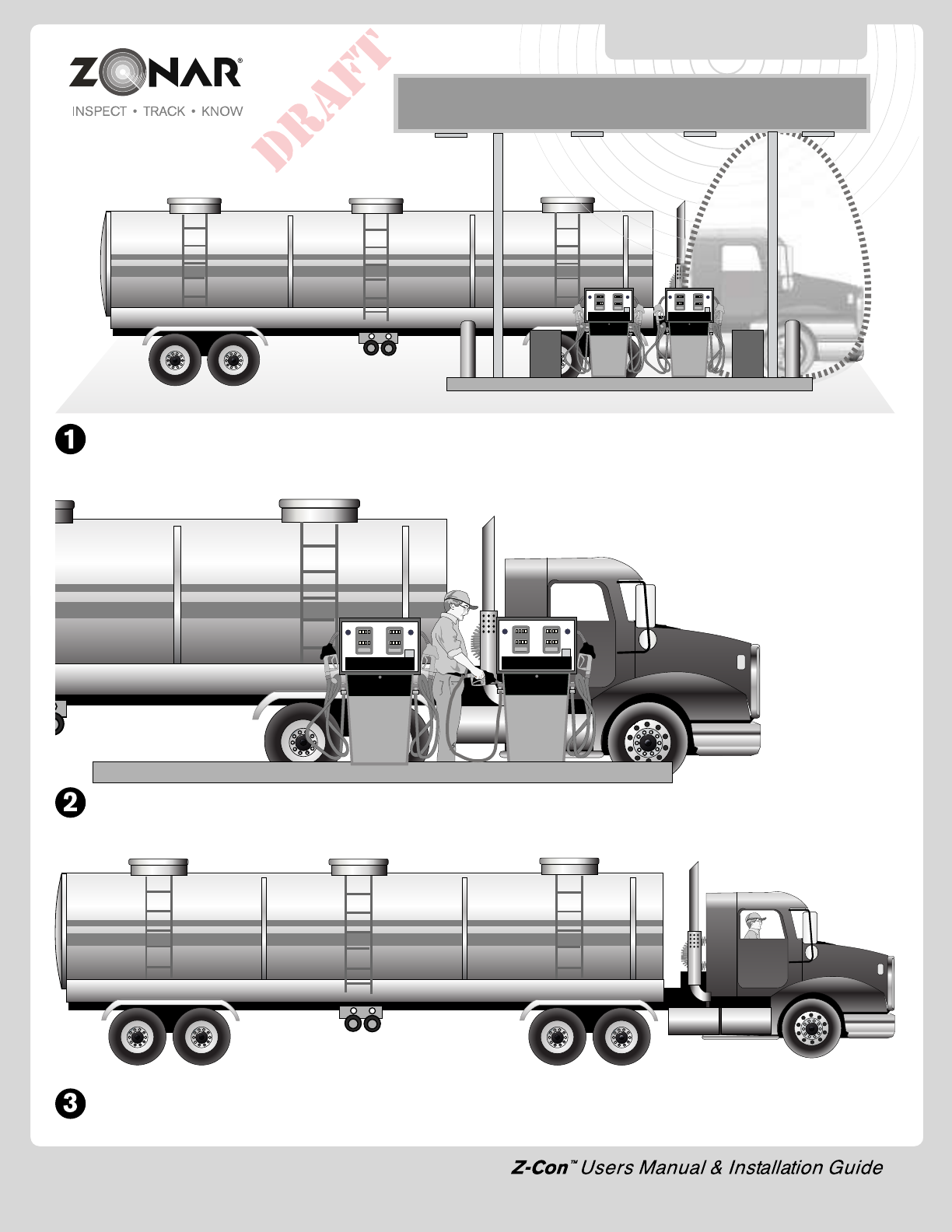
Z-Con detects the truck via ultrasonic sensors and activates the radio in the fuel canopy and infrared transmitter.
The truck’s VIN is validated indicating the truck is authorized to begin fueling.
After fueling has completed, the truck leaves the pump area and the secure connection is broken - ensuring that only the authorized truck
is fueled.

5
Basic Workflow
1) Unpack all equipment and verify shipment (see page 7).
2) Layout system (see page 7)
3) Install and inter-connect system.
A) V2JE device (see page 7).
B) Electrical/JBus data link (see pages 8-10 and page 16).
C) Antenna(s) (see page 12).
D) Truck board windshield mount and truck board (see page 11)
4) Operational checkout V2JE device (see page 14).
5) Provision Truck Board (see page 13).
BASIC WORKFLOW
Layout
1) Cellular/GSM antennas must be located a minimum of 8”
from any person.
2) Mount all equipment in the interior of the vehicle. External
mounted GPS antenna is the only component installed
externally.
3) Do not install Zonar equipment below windows and doors
which open to the vehicles exterior to prevent water damage.
4) Lay all components out prior to installation to check for proper
cable length and interference issues.
5) Avoid mounting equipment in difficult to access areas. Avoid
mounting in areas which do not allow for direct diagnostic
LED viewing.
6) Avoid mounting equipment in dirty, dusty, or damp areas (e.g.
near floors and entrance ways).
7) Avoid mounting Zonar Equipment, antennas and wiring near
other radio equipment (e.g.,two-way radios), PA equipment
and high energy electrical sources (e.g., cables, relays,
amplifiers, etc.)
Electrical
1) Consult the vehicles manufacturer for specific
installation guidelines. (HIGHLY RECOMMENDED for
Multiplex electrical systems)
2) All power leads (V2JE-Power Cable) must be connected to
the vehicles protected circuitry (e.g. fuse panel, circuit breaker
panel, protected circuits). Never electrically connect Zonar
equipment to unprotected circuits.
3) It is also required that all power leads (V2JE-Power Cable)
be protected with a 3 to 5 amp fuse and inline fuse holder
(included) for optimal system protection.
Cable Management
1) Strain relieve and support all cable installations.
2) Avoid sharp bends and tight radius installations of cables.
3) Avoid moving components (e.g. doors, steering shafts, handles,
fans, etc.).
4) Provide an adequate “Service Loop” i.e. “cable slack” to allow
for servicing of equipment.
5) Avoid routing cables thru doors, windows, and other pinch
points.
6) Avoid routing cables in high personnel traffic areas.
7) Avoid routing antenna cables near radio and PA equipment.
6
INCORRECT
• Bend radius too tight
• Hole has sharp edges
• Hole has no grommet
CORRECT
• Bend radius adequate
• Hole has grommet
GENERAL GUIDLINES
Drill Holes
1) Capture all drill chips during drilling operations. Do not allow
drill chips to fall onto electrical equipment, furnishings, heating
ducts, etc. Magnets, sticky tape, vacuums, physical barriers,
etc. may all be used to accomplish this task.
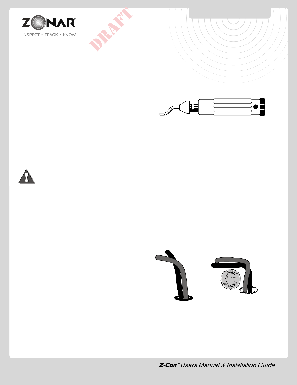
2) Deburr all drill holes on both sides of drilled surface. Example
deburr tool:
3) All drill holes must have a rubber grommet or similar anti-
chaffing system installed to protect cable assemblies (e.g.
plastic conduit).
4) Seal all penetration drill holes which may pass rain water (e.g.
GPS antenna cable).
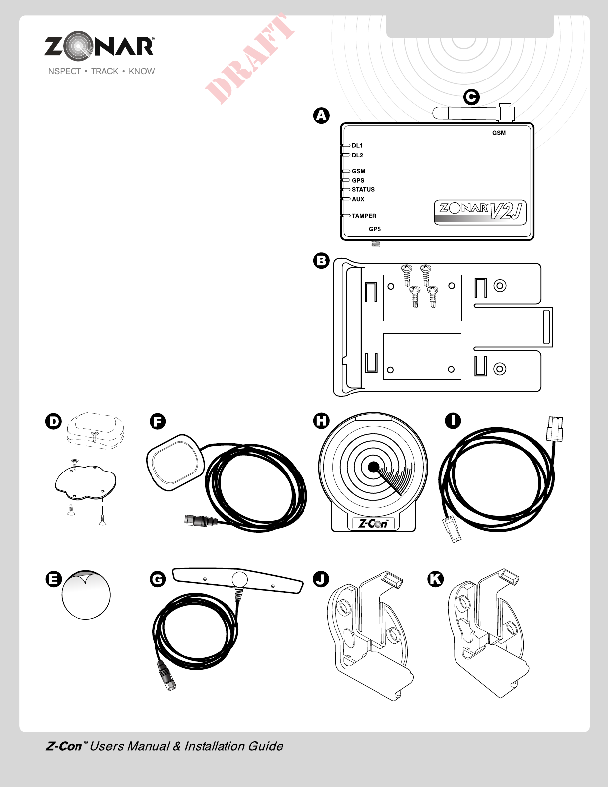
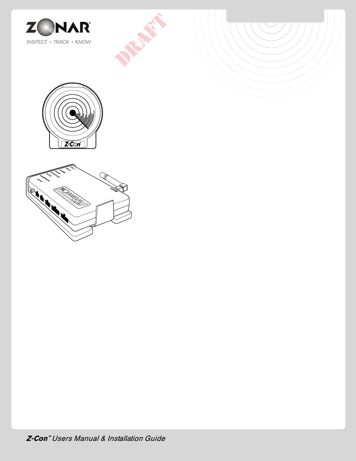
Component Identification
A. V2JE
B.V2JE Mounting Plate and Mounting Screws (provided)
C. Stubby GSM (cellular) Antenna
D.GPS Antenna Aluminum Mount Plate and Screws (optional -
used for non-magnetic exterior rooftop GPS Antenna installs)
E.3M Double Sided Adhesive (used for non-metallic interior roof
attachment) supplied
F. GPS Antenna
G. MiniWing style GSM Antenna (optional)
H. Truckboard Part No. 80510
I. Truckboard Cable - 13 ft. - Part No.80765
J. Standard Back Part No. 80911
K. Angled Back Part No. 80912
Note: See page 11 for detailed information on GPS and GSM
(cellular) antenna requirements and recommendations.
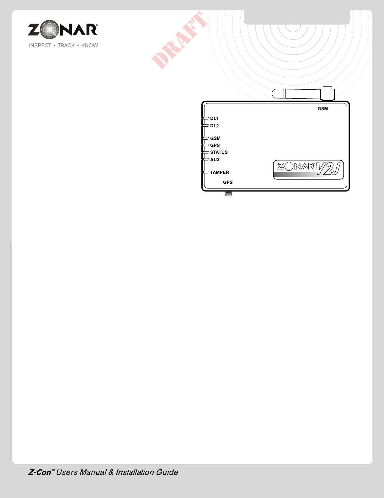
V2JE/TRUCKBOARD
HARDWARE
7
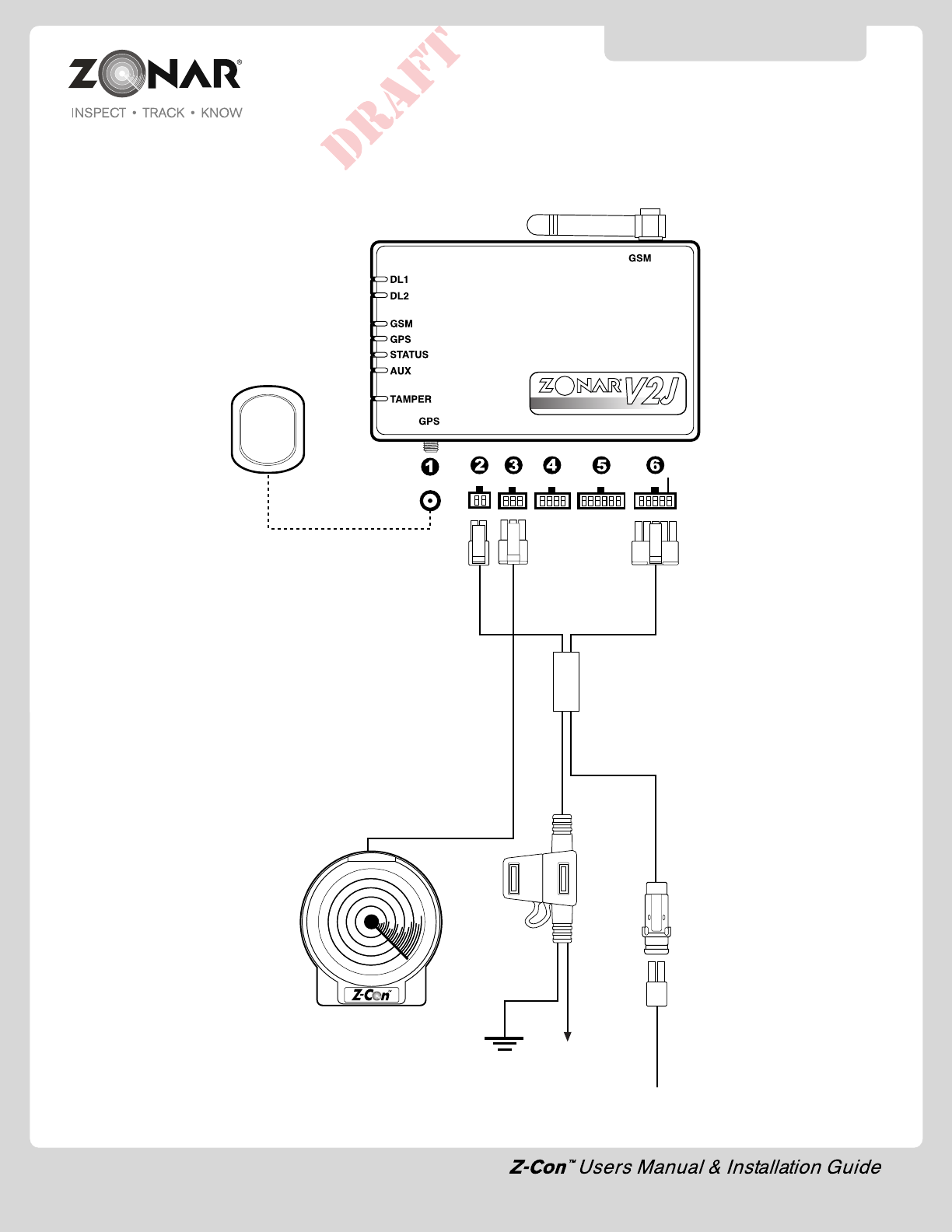
8
ZonarV2J
Part#: 10017
GSM Stubby Antenna
Part#: 10019
1.External GPS antenna
2.4 Pin Power Input
3.Z-Con™ Truck Board
4.8 Pin 2010 Vehicle Mount (Optional)
5.12 Pin Discrete Truckboard I/O (Optional)
6.10 Pin J3 input (JBus 1708/1939 Equipped Vehicles)
SYSTEM INSTALLATION
Constant
Power
Supply
2 Pin
Ground
External GPS Antenna
Part#: 10006
Cable Length: 16.5 ft.
Truckboard
Part#: 80510
Cable Length:13ft ft. - Part# 80765
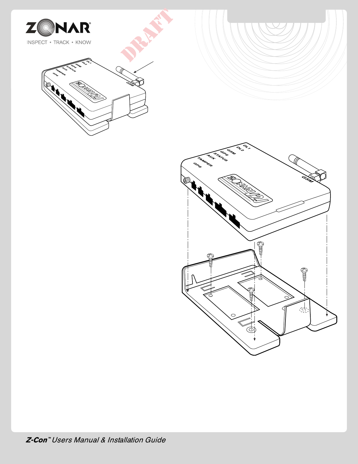
V2JE Mounting Plate & Unit
1)
Follow all General Guidelines as specified on page 6.
2) Mount onto interior flat surface large enough to accommodate
footprint.
3) Do not install below windows or doors which open to the
vehicles exterior to prevent water damage.
4) Avoid mounting equipment in difficult to access areas. Avoid
mounting in areas which do not allow for direct diagnostic
LED viewing.
5) Avoid mounting Zonar Equipment, antennas and wiring near
other radio equipment (e.g.,two-way radios), PA equipment
and high energy electrical sources (e.g., cables, relays,
amplifiers, etc.).
6) Avoid mounting equipment in dirty, dusty, or damp areas (e.g.
near floors and entrance ways).
V2JE MOUNTING PLATE
CAUTION: The mini-GSM antenna
is factory torqued, do not rotate
antenna!!
9
10
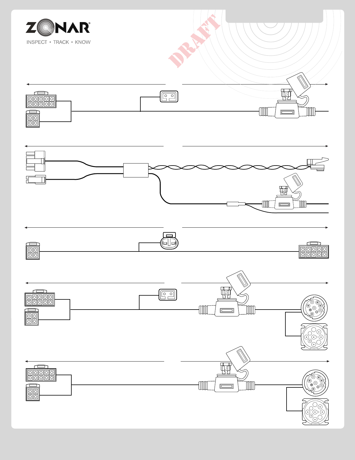
SAMPLE CABLES
PIN 80441 - V2J WW J1939 TO RETRO ADAPTER
9.33’
PIN 80183 - WW 9-PIN PASS THRU WITH PIGTAIL FLANGED PANEL MOIUNT
9.8’
10.75’
PIN 80339 - J1939 - 15 UNIVERSAL NODER AMP ss
See Page 21-22 for Vehicle Specific Requirements
PIN 80444 - V2J WW J1708 2-PIN DELPHI 16.65’
PIN 80130 - WW 6-PIN PASS THRU WITH PIGTAIL FLANGED PANEL MOUNT
9.8’
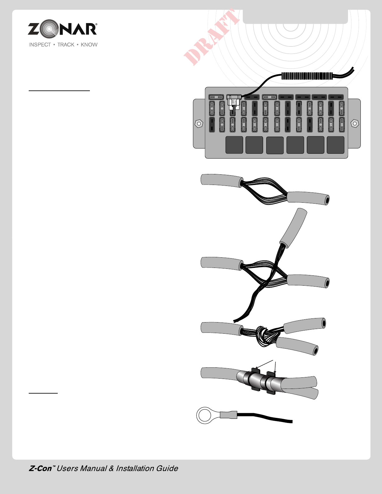
Wiring Guidelines for non-terminated wire ends
CONSTANT POWER:
The authorized method for power termination on the Zonar V2JE
system is the use of Add-a-Circuit fuse taps. Whenever possible,
use fuse taps for power termination. If, due to the particular
make/model/year of the vehicle being installed, fuse taps cannot
be used then the poke and weave method of termination can be
utilized. All wiring terminations MUST be fused regardless of Add-
a-Circuit or poke and weave.
When installing Add-a-Circuit fuse taps, ensure that the fuse tap
seats fully in the correct location. If another fuse, a relay, or any
other object in the fuse panel prevents the fuse tap from seating
fully, relocate the fuse tap. It is not permissible for the fuse tap to
rub or make contact with other items in the fuse panel. In addition,
you must be able to re-secure the fuse panel cover or door once
the fuse tap is installed. Whenever possible, use an empty location
in the fuse panel that does not have an existing fuse. If it is not
possible to use an empty location, ensure that the existing fuse is
placed in the correct location on the fuse tap.
See Fig. 11-1
Whenever it is not possible to utilize Add-a-Circuit fuse taps then
the poke and weave method must be used.
A. First locate the proper wire where the poke and weave method
is to be installed. Strip 3/4” to 1” of insulation from the wire in
the vehicle to be installed. Spread the wire strands apart as
shown. See Fig. 11-2
B. Strip 1” to 1 1/2” of insulation from the wire in the fused link
to be installed. See Fig. 11-3
C. Insert the wire from the fused link into the spread wire in the
vehicle. Wrap around the wire several times. See Fig. 11-4
D. Cover the exposed wires with several wraps of electrical tape
or mastic. Place one wire tie over the electric tape over the
exact location where the wires are 'wrapped' together. Place
another wire tie 1” to 2” from the first wire tie, to secure the two
wires together and as stress relief. See Fig. 11-5
GROUND:
Normally affixed to the vehicle chassis with a high quality solderless
ring lug. Ensure good crimp by giving the finished joint a slight tug.
See Fig 11-6
Fig. 11-1
Wire Tie
Fig. 11-5
Fig. 11-4
Fig. 11-3
Fig. 11-2
WIRING GUIDELINES
CAUTION: Only “LitteFuse”
(www.littlefuse.com) Add-A-
Circuit taps are authorized for
use with Zonar Equipment.
Full size: (ATO) P/N FHA200
Mini version: P/N FHM200
Fig. 11-6
11
12
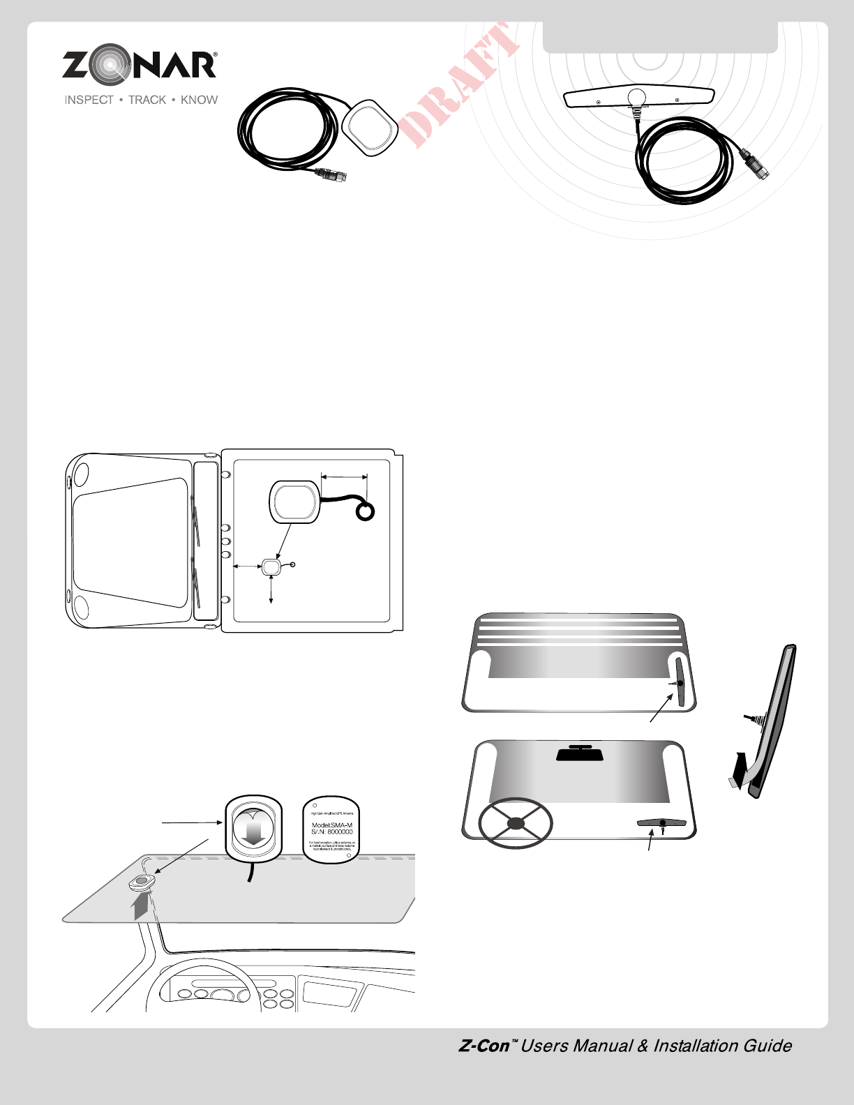
External GPS Antenna
1)
Follow all General Guidelines as specified on page 6.
2) May be magnetically mounted or mounted via optional aluminum
plate and screw for non-magnetic surfaces (see page 7).
3) Interior cab mount - non-metallic roof only
4) Suggested installation point - centerline of vehicle roof, minimize
cable run to prevent wind and truck wash damage.
5) Ensure a clear antenna view of the open sky.
6) Maintain a minimum of 6 inches from any rooftop edge or
ledge (see Fig. 12-1).
7) Drill, Deburr, grommet, weather seal, cable thru hole as required.
Drill hole size - 1/2” (.500”); grommet size - 3/8” (.375”).
Note: For optimal system performance Zonar recommends rooftop
mounting with a clear view of the sky.
Fig. 12-2
Fig. 12-1
ANTENNA INSTALLATION
External Rooftop Mount - Preferred
Interior Cab Mount - Non-Metallic Roof Only
1) Clean and dry the surface before placing. To obtain optimum
adhesion, the surface must be clean and dry. The best surface
cleaning solvent is an isopropyl alcohol/water mixture (rubbing
alcohol).
2) Remove the backing from the peel-and-stick (see fig. 12-2).
Press and hold mounting position for 10 seconds to assure
good adhesion.
Adhere peel-and-stick to
top of antenna
6” minimum
from edge
1” - 2” recommended
Cab View
Sky View
External GSM Antenna
(Optional)
1) The attached GSM (cellular) “stubby” antenna is quite robust
and works well in a wide variety of applications. Generally
external GSM (cellular) antennas are only required if the unit is
enclosed behind a metallic panel or in a metallic box. To check
the quality of the cellular connection, turn on the engine and
the GSM LED should be a solid (non-blinking) green within 2
minutes).
2)
Follow all General Guidelines as specified on page 6.
3) Cellular/GSM antennas must be located a minimum of 8 “ from
any person.
4) Mount on unobstructed interior glass surface (e.g. windshield
corner or stationary side window) with a clear view of open sky.
5) Do not install on metallic surfaces, or in metallic enclosures.
6) Do not block drivers view or mirrors.
7) Verify placement acceptability with state DOT/law enforcement
prior to installation.
8) Positioning - Vertical (Optimum), Horizontal (Alternate) ( see
Fig. 12-3).
9) Clean and dry the surface before placing the mounting plate.
To obtain optimum adhesion, the surface must be clean and
dry. The best surface cleaning solvent is an isopropyl
alcohol/water mixture. (rubbing alcohol)
10) Remove the backing from the peel and stick (see Fig.12-4).
Press and hold mounting position for 10 seconds to assure
good adhesion.
Optimum - Mount Antenna Vertically
Fig. 12-4
Fig. 12-3
Alternative - Mount Antenna Horizontally
Non-Metallic Roof
13
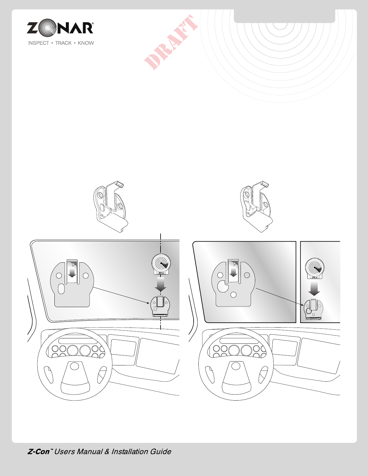
INSTALLATION EXAMPLE
Fig. 13-1
Truck Board Bracket and Truck Board Installation
1) Follow all general guidelines as specified on page 6.
2) Locate proper mounting location. See vehicle specific
information table on pages 21-22.
3) Clean and dry windshield surface. To obtain optimum adhesion
the windshield surface must be clean and dry. The best surface
cleaning solvent is an isopropyl alcohol/water mixture (rubbing
alcohol).
4) Remove the backing from the peel-and-stick (see Fig. 13-1
or 13-2). Press and hold mounting position for 10 seconds to
assure good adhesion.
5) Complete cable routing and connect Truck Board to V2JE
unit.
Fig. 13-2
One Piece Windshield Split Windshield
Standard Back Angled Back
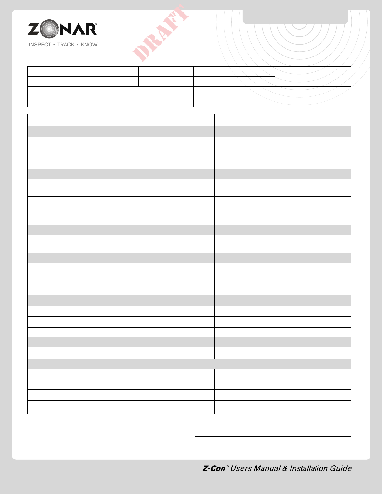
INSTALLER SIGNATURE Date
Customer: Yard: Date: Asset #:
Installer: Location: GPS ID:
Vehicle Odometer Value: Vehicle I.D. (e.g., Vin, Plate#, Make, Model, Year
Vehicle Hour Meter value (if monitoring engine hours)
SYSTEM CHECKLIST
14
System Check Value Notes
General Layout
General condition - components level, even, straight, etc?
System layout conforms to your established standard?
Clearance check - Vehicle Mount to 2010 Hand Held?
Drilling and Cutting
All drill holes grommeted (or otherwise protected), deburred,
sealed (weather penetrations only)
All chips captured?
Vehicle Mount vacuumed and visually verified to be free of
drill chips or other debris?
Cable Management
All cables properly ran (tight radius, interference, strain
relieved, supported, service looped)?
Electrical
System hookup complies to your established standard?
Verify crimp integrity?
Verify fuse holder and fuse installation?
GPS/J3 System checkout
GPS/J3 LED light check? (engine on/engine off)
Verify GPS position uploaded to GTC website?
Verify power On/Off event
Truck Board System
Truck Board properly provisioned?
Post Job
Key accounted for?
Vehicle secure?
Lights, electrical off?
All debris, refuse, chips removed?
15
System Check: Minimum Requirements - GPS
1) At a minimum, the installer must perform a “System Check”
to verify proper installation.
2) This procedure covers the minimum requirements for a system
installer. If at all possible a full and complete checkout using
Zonar’s Ground Traffic Control™ website should be performed.
Not all installers will have access to this area, check with a
Zonar Customer Service representative if in doubt.
3) Turn Key On/Engine running, within 2 minutes:
A) GPS Green LED: LED should be solid within 2 minutes
or less. Blinking indicates acquiring satellites, Solid
indicates satellite acquired. GPS antenna must have
a clear view to sky. Do not proceed further until GPS
LED is solid
B) GSM cellular Green LED: LED should be solid within 2
minutes. If blinking, ensure GSM antenna is secure, has
a clear view to the sky and area has cellular coverage.
C) STATUS Green LED: Solid
V 2J Model if blinking or off
i. Call Zonar
D) DL1: Single green blink 1 x per second if J1708/J1587
data is present
E) DL2: Single green blink 1 x per second if J1939 data
is present
F) AUX Red LED: Off (Solid or blinking in the event of
system failure)
G) TAMPER: Off when unit mounted properly in mounting
plate. Solid “On” when not mounted in mounting plate.
4) Turn Key Off, within 2 minutes:
A) DL1: Disregard
B) DL2: Disregard
C) GSM Green LED: Disregard
D) GPS Green LED: Disregard
E) STATUS Green LED: Blinking (Solid may indicate
a problem, check white lead. Call your Zonar
Customer Service Representative if in doubt)
F) AUX: Off (Solid or blinking in the event of
system failure)
Note: A proper and complete system/LED functional check requires
the engine to be running
GPS SYSTEM CHECK
16
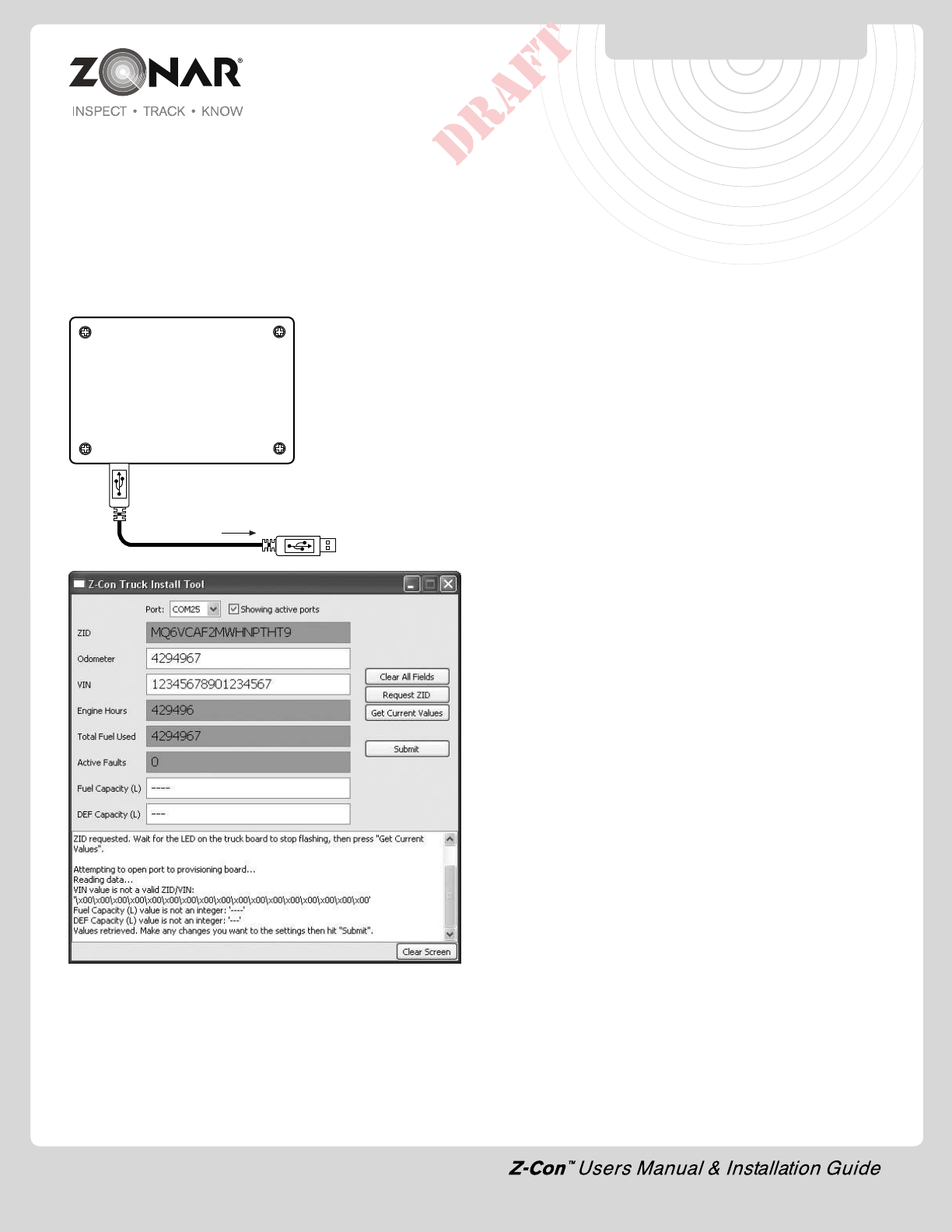
TRUCK INSTALL APP & TOOL
Truck Install App
These tools are for the purpose of ensuring that truck boards
installed in trucks are properly receiving data from the V2J, and to
send information back to Zonar's servers.
The Truck Install/Pump Validation tool is a PCBA with custom
firmware installed on it, along with a standard Zonar radio board,
an IR receiver, and an IR transmitter LED.
The PCBA connects to any
PC via a USB cable
(provided) with the Z-Con
Truck Install App installed.
A screen shot is shown
below.
To Computer
COM port can be selected in the app's dropdown. When a systray
message pops up that says "Your hardware is installed and ready
to use", or something similar, then you can select the tool's COM
port.
If the Truck Install app is running when you plug in a new tool, you'll
need to refresh the COM port list. Do this by unchecking and
rechecking the checkbox next to "Showing active ports" at the
bottom of the app. It may take a moment where it says "Scanning
COM ports..." first.
Standard use and procedure
1) Connect the truck board to the V2J in the truck. Verify it has
power, and the V2J has a GSM connection.
2) Start the truck.
3) Connect the Truck Install tool to your PC via the USB, and
start the Truck Install app.
4) Set the active COM port to the proper port.
5) Point the truck board's IR transmitter at the Truck Install tool's
IR receiver. Click Request ZID. This will cause the truck board
to send its ZID to the Truck Install tool over IR.
6) Once the truck board's green LED stops flashing, click Get
Current Values. This will fill the fields with info gained from the
truck board over radio.
7) Verify that the Engine Hours and Total Fuel are accurate, and
that there are no faults.
8) Make any necessary changes to the Odometer and VIN fields,
fill in Fuel Capacity and DEF Capacity, and click Submit. This
will store the values in non-volatile memory in the V2J.
9) Turn off the truck. The V2J's status light will begin to double-
blink as it sends the new data to the servers. It will single blink
when it's done.
In short, the process is Start truck -> Request ZID -> Get Current
Values -> change values -> Submit -> turn off truck.
Troubleshooting
If the green LED on the truck board does not flash when 'Request
ZID' is pressed:
1) The Truck Install tool might not be receiving power.
-Solution: Check the connections of the USB cable between
the tool and your PC. If problem persists, use a new cable.
2) The wrong COM port may be selected on the Truck Install
app.
-Solution: Select the right COM port for the tool. Try closing
and reopening the app.
If clicking 'Get Current Values' causes the output to return with
"No data received from the truck board" or "Bad data received
from the truck board.", then there are a few possible issues.
1) The return message over radio was corrupt.
- Solution: Bring the Truck Install tool and the truck board
closer together, and click 'Get Current Values' again.
2) The ZID wasn't fully retrieved, or was corrupted.
- Solution: Point the truck board's IR LED directly at the
recessed hole on the left side of the Truck Install tool (as
seen in the picture above). Click 'Request ZID' again. Do
not click 'Get Current Values' until the Truck LED stops
flashing.
Installing the tool
When you first plug in the Truck Install tool, you may need to run
through the automated Windows "Found New Hardware" setup.
Click Next through the dialogs, and the tool should install normally
on your machine.
Thereafter, every time you plug a tool into your machine that hasn't
been plugged in before, you won't need to reinstall the drivers, but
you will need to wait for Windows to identify the tool before its
17
System Specifications
V2JE™
• Operating Temp -20C to +70C
• DC Input range, 8.0Vdc to 30.0Vdc
GPS Receiver
• WAAS Capable
• Very high sensitivity receiver
• Rapid acquisition of satellites
• GPS signal acquisition, tracking and navigation
• On board GPS data storage
GSM/GPRS Transceiver
• Quad Band 850/1900 900/1800
Approved Antennas
• San Jose SM-19 - GPS
• MiniWing GSM 850/1900
• SPK Electronics Co. GSM 850/1900
Important Notice
It is the Owner's sole responsibility to install and use the Zonar
products in a manner that will not cause accidents, personal injury
or property damage. For the purposes of this notice, "Owner",
"you" and "your" means the party (including any person authorized
by that party to use and/or install the Product) that has either: (a)
purchased the Product; or (b) leased the Product from Zonar
Systems, Inc or its related companies. The Owner of this product
is solely responsible for observing safe driving practices. The
choice, location, and installation of all components of the Product
is critical. If installation is not correct, the Product may not perform
at its designed potential or specifications. If in doubt, consult your
vehicle's manufacturer.
SYSTEM SPECIFICATIONS
18
V2JE Troubleshooting
Issue Possible Cause Remedy Notes
GSM, GPS, and Status LED Normal condition Normal condition
solid with engine running
No LED lights Non-issue, unit may be Start engine and ensure
sleeping LEDs illuminate
Vehicle Master Kill switch/ Switch Master Kill switch to
battery disconnected switch “Live” to supply power
set to “Kill” (if equipped) to vehicle
Vehicles electrical system Check for dead battery,
malfunction loose or corroded terminals,
bad crimps or solder joints, etc.
Blown or missing fuse in Replace fuse.
Jbus cable
Vehicle uses Multiplex Rewire unit, outside of
wiring system and has put Multiplex wiring circuit
circuit to sleep
Vehicles Jbus port Check voltages at Jbus
miswired system does not connector or constant lead
always supply constant terminal. Contact Zonar for a
power (direct connect Jbus document on the vehicles
cable) or constant power Jbus electrical values
lead (Backbone style Jbus
cable) is not connected to
a constant power supply
Equipment or cable Test with known good
malfunction vehicle, equipment, or cable
All LEDs go out when Jbus port miswired (direct Check voltages at Jbus
the engine is turned off connect Jbus cable) or connector or constant lead
constant power lead terminal
(backbone style Jbus
cable) is not connected to a
constant power supply
GSM/Cellular LED Non-issue, unit is After turning engine on, give
blinking with engine connecting to cellular the unit up to 3 minutes to
running tower connector to cellular tower
Poor cellular coverage Move vehicle to an area with
area, local cell tower not good cellular coverage
operating correctly
Cellular (stubby) antenna Tighten cellular antenna Do not over-torque -
loose or disconnected damage may result
SIM not activated Call Zonar with GPS serial
number and ask to check
for SIM activation
V2JE TROUBLESHOOTING
19
V2JE Troubleshooting Continued
Issue Possible Cause Remedy Notes
GPS LED blinking with Non-issue, unit is After turning engine on, give If the GPS LED does not
engine running gathering satellite the unit up to 3 minutes to get a solid LED with
information obtain satellite information engine running, GSM
and Status LED will not
behave correctly
Vehicle is located indoors, Move vehicle to an area
under structures, or under where the GPS antenna will
heavy brush have a clear view of the sky
GPS antenna was not Remount GPS antenna
with a clear view of the provide it a clear view to the
open sky open sky
GPS antenna mis-match V2J units have an internal Never connect an
GPS antenna, and are external GPS antenna
typically mounted on the to a V2J. Conversely,
dashboard with a clear view ensure an external GPS
of the sky. V2JE units use antenna with a clear
external GPS antennas that view to the sky is used
are mounted on the vehicles with V2JE models
roof with a clear view of the sky
Status LED - blinking or V2J is not detecting engine Call Zonar
off - engine running RPM from ECM
Status LED - Solid - Equipment or cable Call Zonar
malfunction
AUX/Alert LED solid or Internal issue Call Zonar for a Also see “All LEDs
blinking 3 minutes after replacement unit flashing”
engine start
DL1 and/or DL2 are not Jbus cable not properly Check Jbus cable The DL1 and/or the
blinking green with connected or faulty connections. Replace with DL2 must blink green
engine running known good cable with the engine running
for the system to work
correctly
Vehicles Jbus port Verify pinout and electrical
mis-wired or faulty values from manufacturers
specifications
All LEDs flashing The unit may be booting, For a normal boot, give the
or receiving a Firmware unit up to 3 minutes to
update establish solid LEDs for
GSM, GPS, and Status. For a
Firmware update, give the
unit up to 25 minutes to
receive and install the
Firmware
V2JE TROUBLESHOOTING

20
Troubleshooting
Issue Possible Cause Remedy Notes
Status LED - Blinking or V2J is not detecting engine Check white lead (Switched
off - engine running RPM from ECM Power). It must have 8-
Call Zonar
Status LED - Solid - Switched power is When engine off White- Be sure to check engine
Engine off connected to an incorrect Switched power lead must off, key position ACC.
power source have 0 volts White-Switched power
lead must read 0 VDC
in this state
AUX/Alert LED solid or Internal issue Contact Zonar for a
blinking 3 minutes after replacement unit
engine start
All LEDs flashing The unit may be booting, For normal boot, give the
or receiving a Firmware unit up to 3 minutes to
update establish solid LEDs for GSM,
GPS, and Status. For a
Firmware update, give the
unit up to 25 minutes to
receive and install the
Firmware
DL1 (Jbus 1708) and/or This is normal with the None Normal Operation
DL2 (Jbus 1939) are engine running. Blinking
blinking Green at 1X per Green indicates that Jbus
second data is available from the
ECM. The DL1 and/or the
DL2 must blink green with
the engine running for the
system to work correctly
DL1 (Jbus 1708) are DL2 Engine not running Start Engine
(Jbus 1939) are both off
(Other LEDs appear to be
functioning normally)
Jbus Cable not connected Connect Jbus Cable
Jbus Cable faulty Test with known good cable
Vehicles Jbus connector Verify pinout and electrical
miswired values from manufactures
specifications
DL1 (Jbus 1708) and/or Normal Boot Sequence None Normal Operation
DL2 (Jbus 1939) are Red at
1X per second
TROUBLESHOOTING
21
TRUCK WINDSHIELD
CONFIGURATIONS
Mack
Model Year Vertical Distance from left Distance from right Wiring Harness Comments
Angle
Pinnacle (highway) (single pane)
Titan (heavy haul) (split windshield)
Granite (construction) (split windshield)
CH (split windshield)
Freightliner
Model Year Vertical Distance from left Distance from right Wiring Harness Comments
Angle
Century 2007 70deg 2" from center 32" 1998-2003 80130
2004-current 80183
Coronado 70deg 2" from center 32" 2001-current 80183
Columbia 70deg 2" from center 32" 2001-2003 80130
2004-current 80183
FL series 1999 77deg 42" 28" 1996-2002 80130
2003-current 80183
Legacy 1999 75deg 41" 29"
Classic 2000 77deg 2" from center 29" windshield angled
4 deg to right
Cascadia
M2
Peterbilt
Model Year Vertical Distance from left Distance from right Wiring Harness Comments
Angle
330 2007-2011 80183
335 2007-2009 80441 & 80339
340 2007-2009 80183
365 2008-2009 80441 & 80339
367 2008-2009 80441 & 80339
378, 379 2003 66deg 27" or tight against 2007-2009 80441 & 80339 windshield angled
center 14 deg to right
375, 357, 2007-current 80441 & 80339
377, 385
384 2009-2010 80441 & 80339
386 2007-current 80441 & 80082
387 2007-2009 80441 & 80339
388 2008-2009 80441 & 80082
389 2007-2009 80441 & 80339
587
Info To Come
Info To Come
Info To Come
22
TRUCK WINDSHIELD
CONFIGURATIONS
Kenworth
Model Year Vertical Distance from left Distance from right Wiring Harness Comments
Angle
T600 1999 71deg 31" 27" 2006-current
80441 & 80339
T800 1997-2005 80444
split wrap- 2007 68deg Tight against center 18" 2006-current
around 80441 & 80339
T800 1997-2005 80444 windshield
split flat 2000 68deg tight against center 18" 2006-current 80441 is angled
& 80339 7 deg to starboard
T800 1997-2005 80444
One Piece 2009 66deg measure from right 13" 2006-current 80441 & 80339
T2000 1999 62deg 42" 32"
W900 1997-2005 80444
2006-current 80441 & 80339
International
Model Year Vertical Distance from left Distance from right Wiring Harness Comments
Angle
4700 1999 72deg 37" 29" 1995-1998 80130
1999-2009 80183
4300 2004 64eg 47” 26” 1995-1998 80130
1999-2009 80183
8600 2007 66deg 44" 30" 1995-1998 80130
1999-2009 80183
9000 1992 85deg 36" 31" or tight against 1995-1998 80130 windshield angled
split flat center 1999-2009 80183 7 deg to right
9400 2006 69deg 41" 33" 1995-1998 80130
1999-200980183
ProStar 2011 65deg 45" 27" 2007-current 80183
LoneStar 2009- 2009-2011 80183
2011 should be similar to ProStar
Sterling
Model Year Vertical Distance from left Distance from right Wiring Harness Comments
Angle
Class 8 2002 63deg 41" 27"
Volvo
Model Year Vertical Distance from left Distance from right Wiring Harness Comments
Angle
VNL670, 2006 72deg 43" 31" 2000-current 80441
VHD, VT & 800282
23
1) Only used during checkout “Status” LED does not illuminate
solid green when engine is running
2) Follow all General Guidelines as specified on page 6.
3) All power leads must be connected to the vehicles protected
circuitry (e.g. fuse panel, circuit breaker panel, protected
circuits). Never electrically connect Zonar equipment to
unprotected circuits. (e.g. directly to battery)
4) It is also required that all power leads (Red and White leads)
be protected with a 3 to 5 amp fuse and inline fuse holder
(included) for optimal system protection.
5) Electrical fuses should be installed as close as possible to the
source of power
5) Power Bundle wiring – 4 Pin, 3 wires
A) Red – Constant DC (+8 VDC - +30 VDC), dependent
on system type)
B) Black – Ground must be less than 1 ohm (measure from
4 Pin connector to chassis attachment point)
C) White - Switched Power
The White wire must be connected to a power source
that is active only when the engine is running or the
system will not track idle time properly
1) Engine running (+8 VDC to +30 VDC)
2) Engine NOT running (0 VDC)
3) Engine not running (key position ACC or Accessory
Mode (0 VDC)
Please contact the vehicle manufacturer for any specific
electrical questions
GPS 4 Pin Power Cable
Connect White/Red
Wires to Protected
Fused Terminal
Caution
Connect White/Red
Wires to Protected
Fused Terminal
Caution
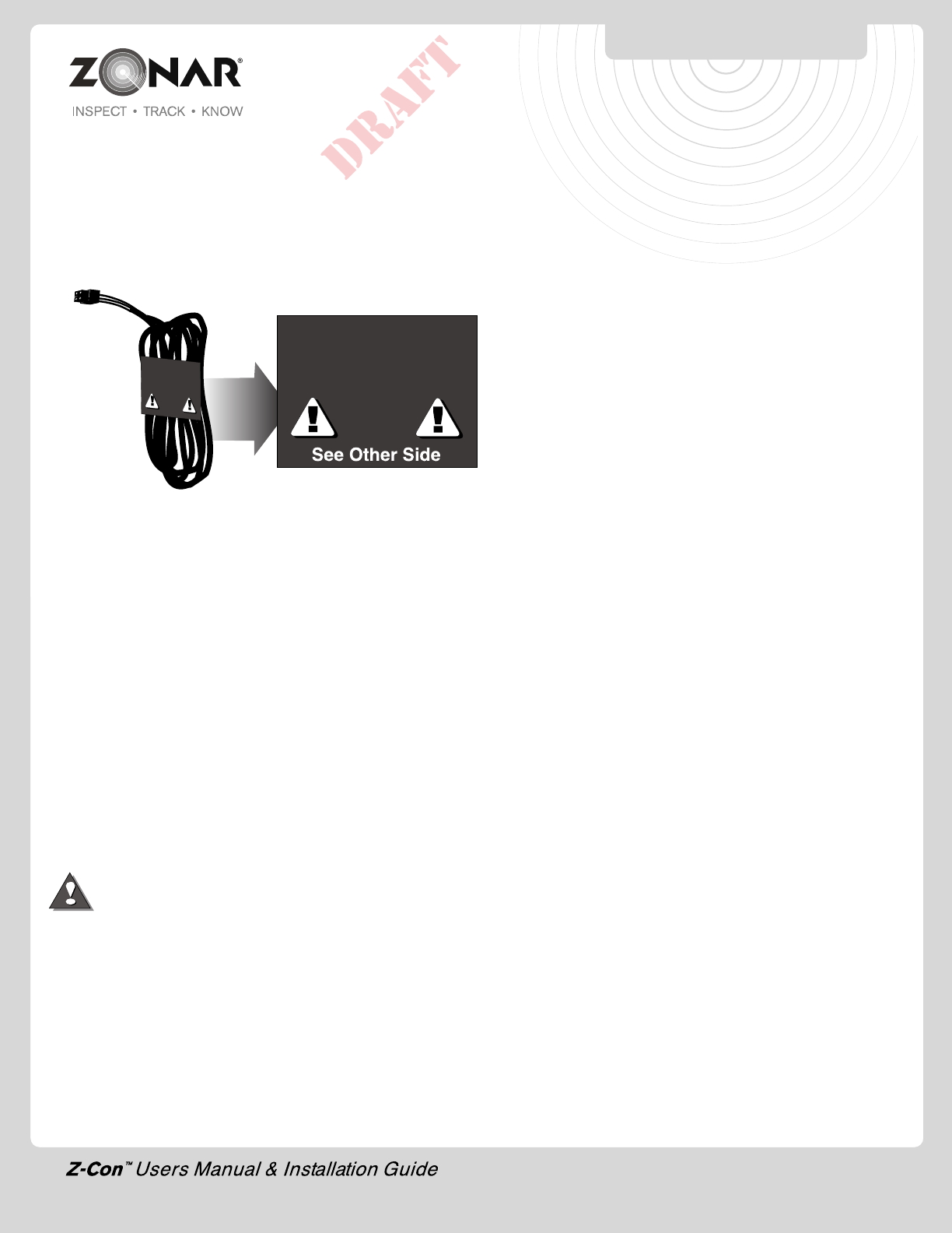
NON-TYPICAL
SYSTEM INSTALLATION
Note: Do not follow the instructions on this page unless
so instructed by a Zonar representative
Limited Warranty
LIMITED WARRANTY: Zonar® warrants that the Hardware provided
under Zonar’s Subscription Agreement is free from material defects
in workmanship for a period of one year for hardware purchased
by customer. THIS LIMITED WARRANTY IS MADE TO CUSTOMER
ONLY AND IS IN LIEU OF ALL OTHER WARRANTIES, EXPRESS
OR IMPLIED. Zonar EXPRESSLY DISCLAIMS ANY IMPLIED
WARRANTY OF MERCHANTABILITY AND FITNESS FOR A
PARTICULAR PURPOSE, AND ANY WHICH MAY ARISE FROM
COURSE OF PERFORMANCE, COURSE OF DEALING OR USAGE
OF TRADE
CUSTOMER’S SOLE AND EXCLUSIVE REMEDY AND ZONAR’S
ENTIRE OBLIGATION UNDER THESE LIMITED WARRANTIES for
defective equipment is the repair and replacement of the equipment
free of charge by Zonar. Zonar shall not be liable to Customer or
any third party for any general, special, punitive, incidental, indirect
or consequential damages, or any lost profits or business, arising
out of Zonar’s Subscription Agreement.
FCC Compliance Statement (Part 15.19)
This device complies with Part 15 of the FCC Rules and with RSS-
210 of Industry Canada (IC). Operation is subject to the following
two conditions:
1. This device may not cause harmful interference, and
2. This device must accept any interference received, including
interference that may cause undesired operation.
Warning: (Part 15.21)
Changes or modifications not expressly approved by Zonar Systems
could void the user's authority to operate the equipment.
Caution: RF Exposure (OET Bulletin 65)
To comply with FCC RF exposure requirements for mobile
transmitting devices, the antenna(s) used for this transmitter must
be installed to provide a separation distance of at least 20cm (8
Inches) from all persons and must not be co-located or operating
in conjunction with any other antenna or transmitter. Users and
installers must be provided with antenna installation instructions
and transmitter operating conditions for satisfying RF exposure
compliance.
Use only supplied and approved antenna's. Use of unauthorized
antenna's or modifications could impair signal quality, void your
warranty and/or result in violation of FCC regulations.
Industry Canada Compliance Statements
"This device has been designed to operate with an antenna having
a maximum gain of [5] dB. Antenna having a higher gain is strictly
prohibited per regulations of Industry Canada. The required antenna
impedance is [50] ohms."
"To reduce potential radio interference to other users, the antenna
type and its gain should be so chosen that the equivalent is
isotropically radiated power (EIRP) is not more than that required
for successful communication."
"The installer of this radio equipment must ensure that the antenna
is located or pointed such that it does not emit RF field in excess
of Health Canada limits for the general population; consult Safety
Code 6, obtainable from Health Canada's website, www.hc-
sc.gc.ca/rpb"
WARRANTY & NOTICES
FCC/IC COMPLIANCE
24

© 2011 Zonar Systems • All Rights Reserved.
REV: 09/15/11
NOTES