Zonar Systems 81010 81010 User Manual
Zonar Systems Inc 81010
User Manual
REV: 08/24/12

As Zonar Systems is continuously improving the Product, Zonar may make changes to the Product at any time which may not be reflected in this document.
INTRODUCTION
2
Zonar Systems Virtual Trainer™ Hardware Installation
Tips for Professional Installers
Zonar Systems’ equipment will provide years of reliable service if properly installed and maintained.
Zonar equipment is typically installed in heavy vehicle applications and is often subject to extreme
temperatures, dust, dirt, vibration, and shock. Proper installation is the critical first step to equipment
longevity and optimal performance.
This guide is meant to be a general guideline for the professional installer and technician. While we
attempt to point out the most common installation questions and issues; common sense, good
housekeeping procedures, attention to detail, safety adherence, and technical competence of the
professional installer is critical for a successful installation.
Please refer to your specific vehicle manufacturer guidelines for the installation of electrical components
and wiring.
A professional team of Zonar support technicians and engineers are available to answer your installation
questions. Contact Zonar at 1-877-843-3847 or by email at customercare@zonarsystems.com.
Thank you,
Jeff Wells
Field Service Manager - Zonar Systems
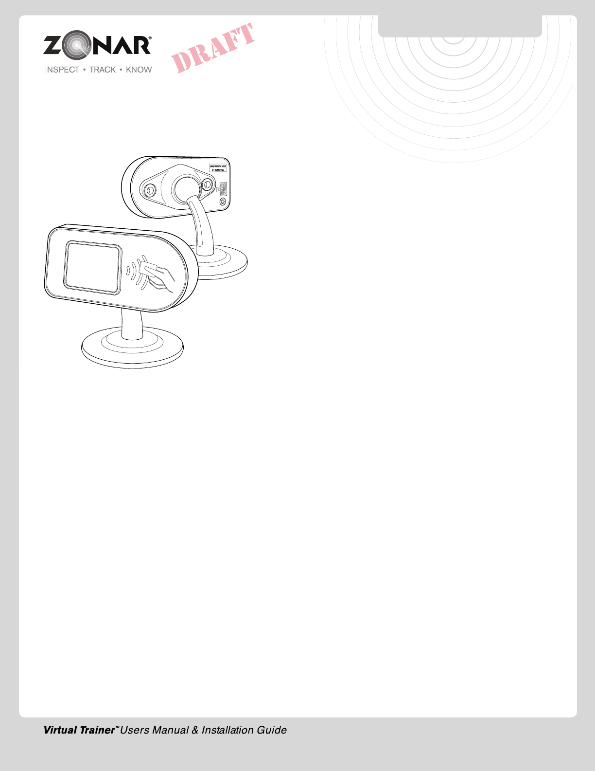
TABLE OF CONTENTS
3
© 2012 Zonar Systems • EVIR, ZPass,Ground Traffic Control and V3 are trademarks of
Zonar Systems. All Rights Reserved.
Products and services protected by one or more of the following US patents: 6,671,646;
6,804,626; 7,557,696; 7,117,121; 7,362,229; 7,564,375; 7,680,595; 7,776,499;
7,808,369; 7,944,345; 8,106,757, plus EP 2756504.3 and the AU.
REV: 08/24/12
Virtual Trainer™
Introduction .......................................................................................2
System Overview...............................................................................4
Equipment.........................................................................................5
System Specifications........................................................................6
General Guidelines.............................................................................7
Installation ........................................................................................8
System Checklist...............................................................................9
Warranty & Notices - FCC Compliance ............................................10
Notes...............................................................................................11
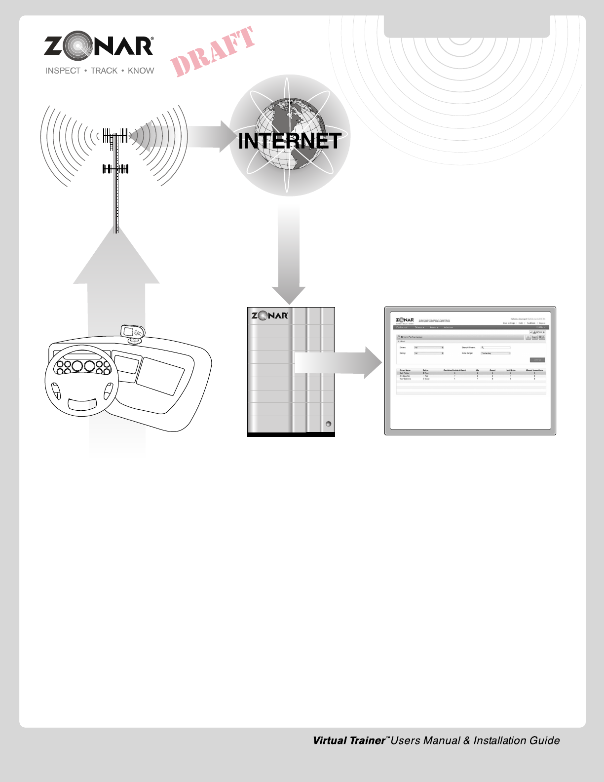
SYSTEM OVERVIEW
4
• RFID to log drivers into vehicle
•Displays warnings and alerts to
improve driver performance
• Track driver performance over
time
CUSTOMER
On-Site Location
ZONAR
Secure Servers
Encrypted Data
Transmissions
CELL TOWER
INTERNET
VIRTUAL TRAINER™
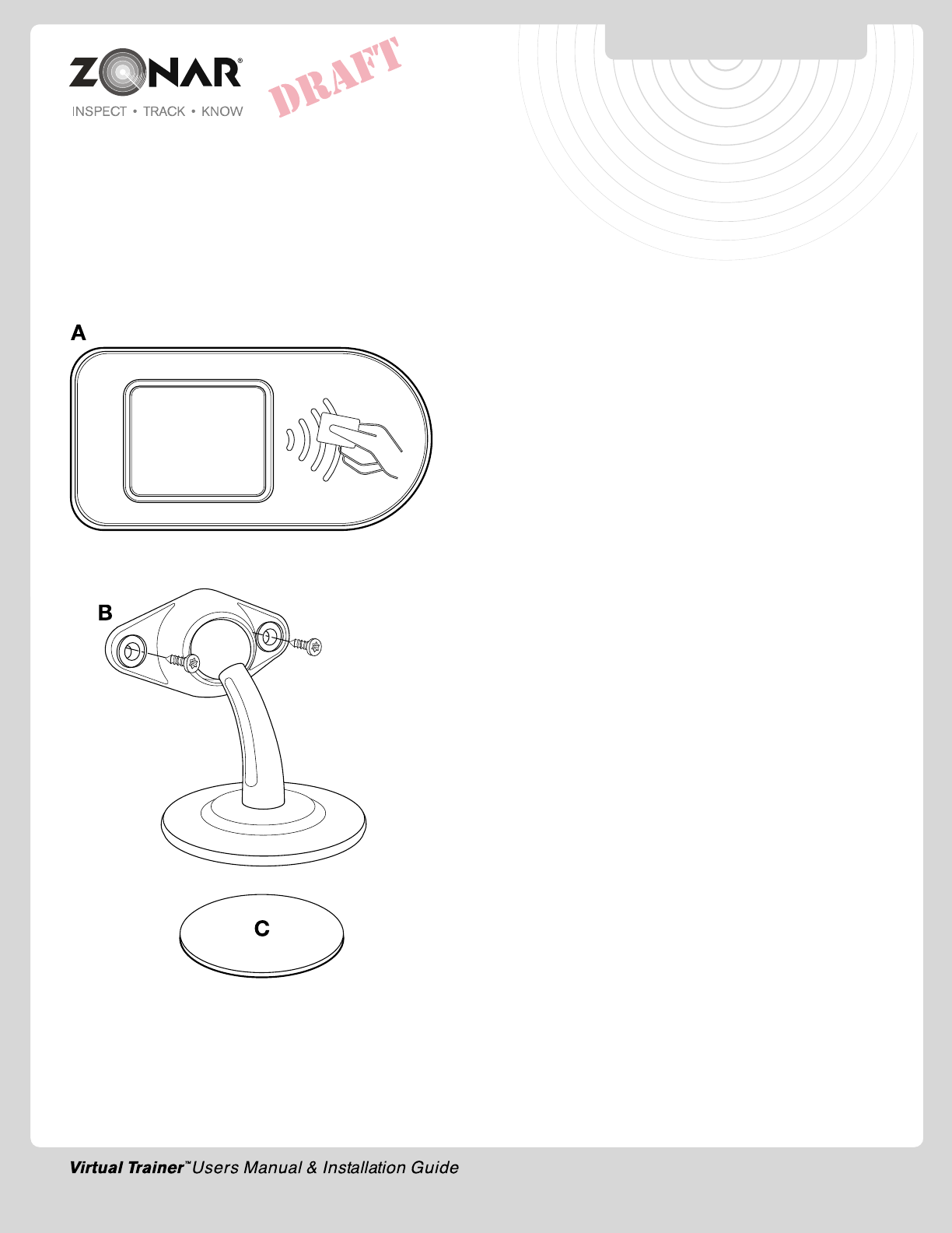
EQUIPMENT
5
A.VIRTUAL TRAINER
B.VIRTUAL TRAINER Mounting Plate and Mounting Screws
(Provided)
C. Mounting Plate adhesive pad
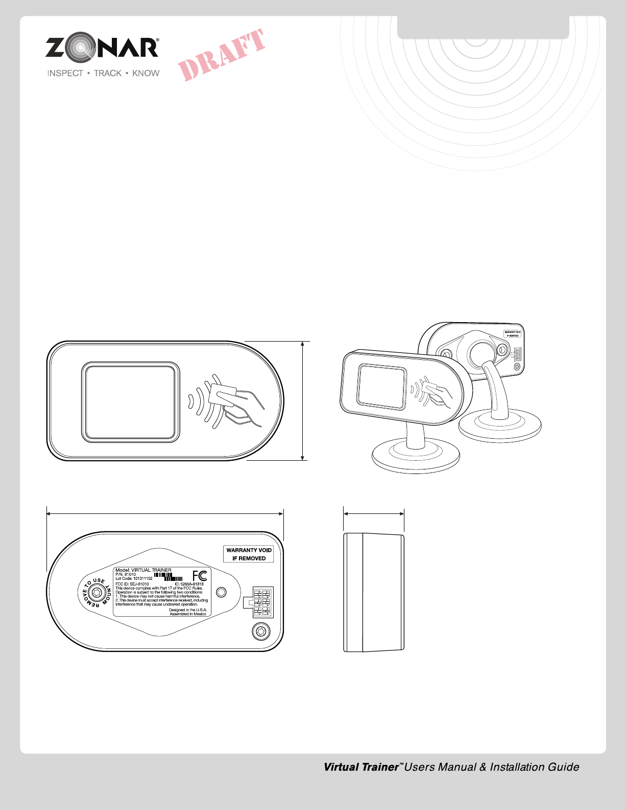
VIRTUAL TRAINER
SPECIFICATIONS/DIMENSIONS
6
1.827
3.627
.927
DIMENSIONS IN INCHES
System Specifications
VIRTUAL TRAINER™
• Operating Temp -40C to +85C
• Operating Humidity to 95%
• DC Input range, 5Vdc - Supplied from Host
Connector
• 6 pin Molex
RFID Reader
• Reads Driver Card from a range of at least 1/2 inch
Host Devices
• V2™, V2J™, VTECU™, V3™
Important Notice
It is the Owner's sole responsibility to install and use the Zonar
products in a manner that will not cause accidents, personal injury
or property damage. For the purposes of this notice, "Owner",
"you" and "your" means the party (including any person authorized
by that party to use and/or install the Product) that has either: (a)
purchased the Product; or (b) leased the Product from Zonar
Systems, Inc or its related companies. The Owner of this product
is solely responsible for observing safe driving practices. The
choice, location, and installation of all components of the Product
is critical. If installation is not correct, the Product may not perform
at its designed potential or specifications. If in doubt, consult your
vehicle's manufacturer.
7
GENERAL GUIDELINES
Layout
1) V3 unit must be located a minimum of 8” from any person.
2) V3 has a temperature range of -40˚C (-40˚F) to +85˚C (+185˚F).
Do not mount V3 in hot engine compartments or near hot
exhaust components.
3) Lay all components out prior to installation to check for proper
cable length and interference issues.
4) Avoid mounting Zonar equipment, antennas and wiring near
other radio equipment (e.g.,two-way radios), PA equipment
and high energy electrical sources (e.g., cables, relays,
amplifiers, etc.).
Electrical
1) Consult the vehicle’s manufacturer for specific
installation guidelines. (HIGHLY RECOMMENDED for
Multiplex electrical systems)
2) All power leads (Red and White Power leads) must be
connected to the vehicles protected circuitry (e.g. fuse panel,
circuit breaker panel, protected circuits). Never electrically
connect Zonar equipment to unprotected circuits (e.g. directly
to battery).
3) It is also required that all power leads (Red and White Power
leads) be protected with a 3 to 5 amp fuse and inline fuse
holder (included) for optimal system protection.
4) Electrical fuses should be installed as close as possible to
the source of power.
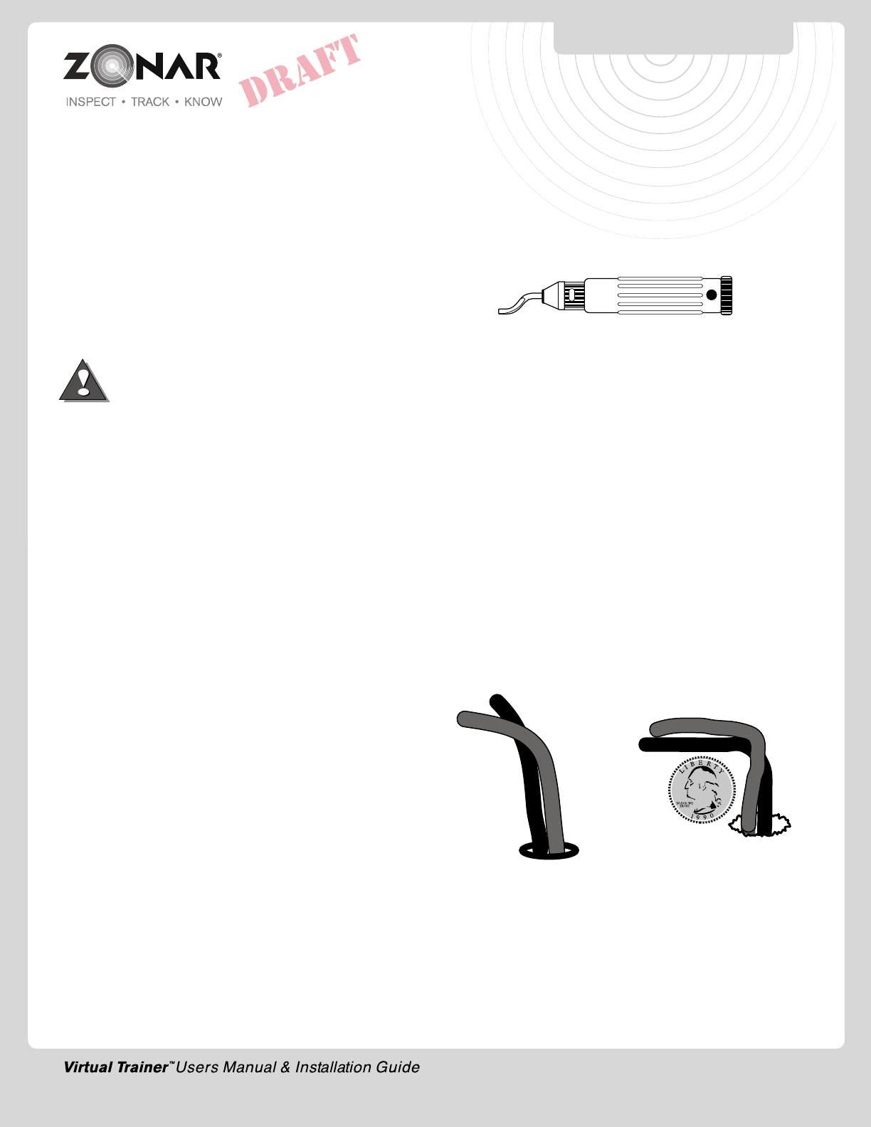
Drill Holes
1) Do not drill into the V3 unit. This will void the warranty.
2) Capture all drill chips during drilling operations. Do not allow
chips to fall onto equipment, furnishings, etc.
3) Deburr all drill holes on both sides of drilled surface. Example
deburr tool:
4) All drill holes must have a rubber grommet or similar anti-
chaffing system installed to protect cable assemblies (e.g.
plastic conduit).
5) Seal all penetration drill holes which may pass rain water.
Cable Management
1) Strain relieve and support all cable installations.
2) Avoid sharp bends and tight radius installations of cables.
3) Avoid moving components (e.g. doors, steering shafts, handles,
fans, etc.).
4) Provide an adequate “Service Loop” i.e. “cable slack” to allow
for servicing of equipment.
5) Avoid routing cables thru doors, windows, and other pinch
points.
6) Avoid routing cables in high personnel traffic areas.
7) Avoid routing antenna cables near radio and PA equipment.
INCORRECT
• Bend radius too tight
• Hole has sharp edges
• Hole has no grommet
CORRECT
• Bend radius adequate
• Hole has grommet
General Housekeeping
1) Capture all drill chips during drilling operations. Do not allow
drill chips to fall onto electrical equipment, furnishings, heating
ducts, etc. Magnets, sticky tape, vacuums, physical barriers,
etc. may all be used to accomplish this task.
2) Remove excess sealant. Sealant should be debris/contaminant
free (e.g. drill chips), consistent, and uniform in appearance.
3) Clip excess wire tie protrusions.
8
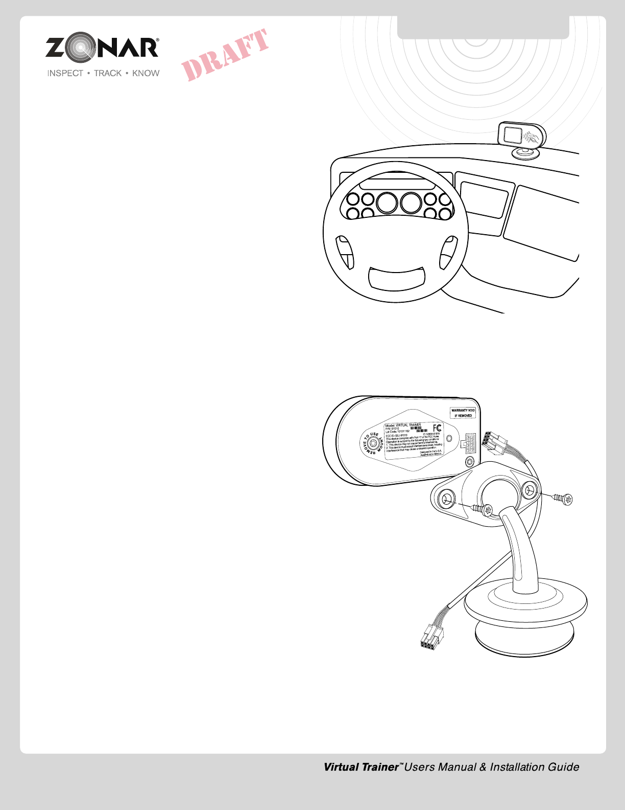
VIRTUAL TRAINER Mounting Plate & Unit
1) Follow General Guideline on page 7.
2) Suggested mounting areas include horizontally
atop dashboard. Verify placement acceptability
with state DOT/law enforcement prior to installation.
See Fig 7-1.
3) Mount onto interior surface large enough to
accommodate mounting bracket footprint.
4) Do not install below windows or doors which open
to the vehicles exterior to prevent water damage.
5) Avoid mounting equipment in difficult to access
areas. Avoid mounting in areas which do not allow
for direct viewing.
6) Avoid mounting Zonar Equipment, antennas and
wiring near other radio equipment (e.g., two-way
radios), PA equipment and high energy electrical
sources (e.g., cables, relays, amplifiers, etc.).
7) Avoid mounting equipment in dirty, dusty, or damp
areas (e.g. near floors and entrance ways).
Fig 7-1
VIRTUAL TRAINER™
INSTALLATION
6 Pin Molex
To Host
Mount
Adhesive
Pad
Fig 7-2
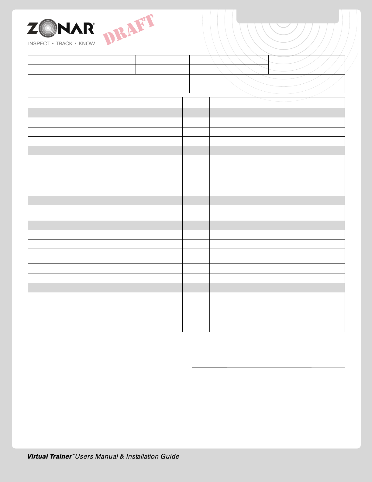
9
VIRTUAL TRAINER™
CHECK LIST
INSTALLER SIGNATURE Date
System Check Yes/No Notes
General Layout
General condition - components level, even, straight, etc?
System layout conforms to your established standard?
Clearance check - Vehicle Mount to 2010 Hand Held?
Drilling and Cutting
All drill holes grommeted (or otherwise protected), deburred,
sealed (weather penetrations only)
All chips captured?
Vacuumed and visually verified to be free of
drill chips or other debris?
Cable Management
All cables properly ran (no tight radius, no interference, strain
relieved, supported, service looped)?
Electrical
System hookup complies to your established standard?
Red lead voltage verified? (12V constant)
White lead voltage verified? Engine on-12V, engine off-OV,
key-accessory position with engine off-OV
Black lead continuity verified? (Grounded to vehicle chassis)
Verify crimp integrity?
Post Job
Key accounted for?
Vehicle secure?
Lights, electrical off?
All debris, refuse, chips removed?
Customer: Yard: Date: Asset #:
Installer: Location: GPS ID:
Vehicle Odometer Value: Vehicle I.D. (e.g., Vin, Plate#, Make, Model, Year
Vehicle Hour Meter value (if monitoring engine hours)
10
Limited Warranty
LIMITED WARRANTY: Zonar warrants that the Hardware provided
under this agreement is free from all material defects in workmanship
under normal use and service. Zonar’s warranty period for its
Hardware is as follows:
V3 Product Line - 5 Years
EVIRTM - 3 Years
All Other Hardware - 1 Year
The above warranty periods run from the date of shipment. Provided
that the Hardware is used and handled as intended, Zonar will
replace any failed or functionally impaired Hardware with equivalent
Hardware in terms of performance and functionality.
This warranty does not apply to any Hardware that has been
misused, altered, willfully abused or that has been damaged due
to improper installation by the customer.† Hardware installations
must follow Zonar’s equipment specific installation guidelines.† If
product returned is determined to be damaged due to any of the
aforementioned circumstances, the Customer will be charged the
price of a refurbished unit plus shipping and handling.
CUSTOMER’S SOLE AND EXCLUSIVE REMEDY AND ZONAR’S
ENTIRE OBLIGATION UNDER THESE LIMITED WARRANTIES for
defective equipment is the repair and replacement of the equipment
free of charge by Zonar. Zonar shall not be liable to Customer or
any third party for any general, special, punitive, incidental, indirect
or consequential damages, or any lost profits or business, arising
out of Zonar’s Subscription Agreement.
FCC Compliance Statement (Part 15.19)
IC Compliance Statement (RSS-210)
This device complies with Part 15 of the FCC Rules and with RSS-
210 of Industry Canada (IC). Operation is subject to the following
two conditions:
1. This device may not cause harmful interference, and
2. This device must accept any interference received, including
interference that may cause undesired operation.
Warning: (Part 15.21)
Changes or modifications not expressly approved by Zonar Systems
could void the user's authority to operate the equipment.
Caution: RF Exposure (OET Bulletin 65)
To comply with FCC RF exposure requirements for mobile
transmitting devices, the antenna(s) used for this transmitter must
be installed to provide a separation distance of at least 20cm (8
Inches) from all persons and must not be co-located or operating
in conjunction with any other antenna or transmitter. Users and
installers must be provided with antenna installation instructions
and transmitter operating conditions for satisfying RF exposure
compliance.
Use only supplied and approved antenna's. Use of unauthorized
antenna's or modifications could impair signal quality, void your
warranty and/or result in violation of FCC regulations.
Industry Canada Compliance Statements
"This device has been designed to operate with an antenna having
a maximum gain of [5] dB. Antenna having a higher gain is strictly
prohibited per regulations of Industry Canada. The required antenna
impedance is [50] ohms."
"To reduce potential radio interference to other users, the antenna
type and its gain should be so chosen that the equivalent is
isotropically radiated power (EIRP) is not more than that required
for successful communication."
"The installer of this radio equipment must ensure that the antenna
is located or pointed such that it does not emit RF field in excess
of Health Canada limits for the general population; consult Safety
Code 6, obtainable from Health Canada's website, www.hc-
sc.gc.ca/rpb."
WARRANTY & NOTICES
FCC/IC COMPLIANCE

11
NOTES

VIRTUAL TRAINER™
USERS MANUAL
& INSTALLATION GUIDE
12
© 2012 Zonar Systems • All Rights Reserved.
REV: 08/24/12