Zonar Systems ZPASSH9045 Long Range RFID Reader H9045 User Manual
Zonar Systems Inc Long Range RFID Reader H9045 Users Manual
UserManual.wiki
>
Zonar Systems
>
ZPASSH9045 User Manual
Users Manual
Navigation menu
Upload a User Manual
Namespaces
Wiki Guide
HTML
PDF
Info
Views
User Manual
Discussion / Help
Navigation
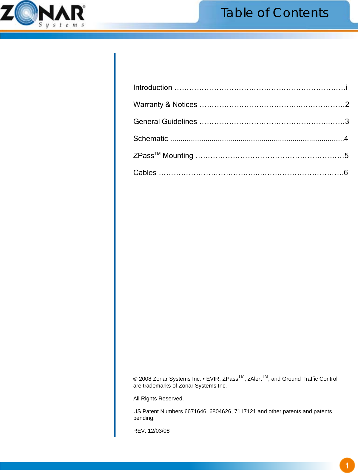
![Warranty & Notices Limited Warranty Zonar® will provide customer with a replacement for nonconforming hardware or software within a commercially reasonable time after timely notice from customer. Zonar does not represent or warrant that the hardware and software are free of bugs or errors and shall not be liable for any losses (financial or non-financial) occurring as a result of such bugs or errors. No other warranty expressed or implied, including any warranties of merchantability or particular purpose, is provided for any hardware or software provided pursuant to this contract. Zonar Systems shall not be liable to customer, or any third-party for any general, special, punitive, incidental, indirect or consequential damages, or any loss of profits or business, arising out of this agreement. The terms and conditions of this agreement shall apply to any replacement hardware and software furnished. CUSTOMER’S SOLE AND EXCLUSIVE REMEDY AND ZONAR’S ENTIRE OBLIGATION UNDER THESE LIMITED WARRANTIES IS TO REPAIR OR REPLACE THE PRODUCTS WITH CONFORMING PRODUCTS SUBJECT TO PROMPT ONTICE FROM LICENSEE OF NON-CONFORMITY AND AT ZONAR’S OPTION IF SUCH ALTERNATIVES ARE NOT FEASIBLE, TO TERMINATE THIS AGREEMENT AND REFUND THE APPLICABLE FEED PAID WITH RESPECT TO SUCH NON-CONFORMING PRODUCT. THIS DISCLAIMER OF WARRANTIES IS AN ESSENTIAL CONDITION OF THE AGREEMENT. This device complies with Part 15 of the FCC Rules and with RSS-210 of Industry Canada (IC). Operation is subject to the following two conditions: 1. This device may not cause harmful interference, and, 2. This device must accept any interference received, including interference that may cause undesired operation. Changes or modifications not expressly approved by Zonar Systems could void the user’s authority to operate the equipment. To comply with FCC RF exposure requirements for mobile transmitting devices, the antenna(s) used for this transmitter must be installed to provide a separation distance of at lest 20cm (8 inches) from all persons and must not be co-located or operating in conjunction with any other antenna or transmitter. Users and installers must be provided with antenna installation instructions and transmitter operating conditions for satisfying RF exposure compliance. Use only supplied and approved antenna’s. Use of unauthorized antenna’s or modifications could impair signal quality, void your warranty and/or result in violation of FCC regulations. “This device has been designed to operate with an antenna having a maximum gain of [5] dB. Antenna having a higher gain is strictly prohibited per regulations of Industry Canada. The required antenna impedance is [50] ohms.” “To reduce potential radio interference to other users, the antenna type and its gain should be so chosen that the equivalent is otropically radiated power (EIRP) is not more than that required for successful communication.” “The installer of this radio equipment must ensure that the antenna is located or pointed such that it does not emit RF field in excess of Health Canada limits for the general population; consult Safety Code 6, obtainable from Health Canada’s website, www.hc-sc.gc.ca/rpb” Warning: (Part 15.21) FCC Compliance Statement (Part 15.19) Caution: RF Exposure (OET Bulletin 65) Industry Canada Compliance Statements](https://usermanual.wiki/Zonar-Systems/ZPASSH9045/User-Guide-1164852-Page-4.png)