Zonar Systems ZPASSH9045 Long Range RFID Reader H9045 User Manual
Zonar Systems Inc Long Range RFID Reader H9045 Users Manual
Users Manual

As Zonar Systems is continuously improving the Product, Zonar may make changes to the Product at any time which may not be reflected in this document.
Zonar Systems Hardware Installation Tips
For Professional Installers
Zonar Systems equipment will provide years of reliable service if properly installed and
maintained. Zonar equipment is typically installed in heavy vehicle applications and is
often subject to extreme temperatures, dust, dirt, vibration, and shock.
Proper installation
is the critical first step to equipment longevity and optimal performance.
This guide is meant to be a
general guideline
for the professional installer and technician.
While we attempt to point out the most common installation questions and issues; common
sense, good housekeeping procedures, attention to detail, safety adherence, and technical
competence of the professional installer is critical for a successful installation.
Please refer to your specific vehicle manufacturer guidelines for the installation of
electrical components and wiring.
A professional team of Zonar support technicians and engineers are available to answer
your installation questions. Contact Zonar at 1-877-843-3847 or by email at
support@zonarsystems.com.
Thank you,
Andre J Horochiwsky
Customer Support Manager – Zonar Systems
Introduction

Table of Contents
Introduction ……………………………………………………………i
Warranty & Notices …………………………………..………………2
General Guidelines ……………………………………………..……3
Schematic ....................................................................................4
ZPassTM Mounting ……………………………………………………5
Cables …………………………………..…………………………….6
© 2008 Zonar Systems Inc. • EVIR, ZPassTM, zAlertTM, and Ground Traffic Control
are trademarks of Zonar Systems Inc.
All Rights Reserved.
US Patent Numbers 6671646, 6804626, 7117121 and other patents and patents
pending.
REV: 12/03/08
Warranty & Notices
Limited Warranty
Zonar® will provide customer with a replacement for
nonconforming hardware or software within a
commercially reasonable time after timely notice from
customer. Zonar does not represent or warrant that
the hardware and software are free of bugs or errors
and shall not be liable for any losses (financial or non-
financial) occurring as a result of such bugs or errors.
No other warranty expressed or implied, including any
warranties of merchantability or particular purpose, is
provided for any hardware or software provided
pursuant to this contract. Zonar Systems shall not be
liable to customer, or any third-party for any general,
special, punitive, incidental, indirect or consequential
damages, or any loss of profits or business, arising
out of this agreement. The terms and conditions of
this agreement shall apply to any replacement
hardware and software furnished.
CUSTOMER’S SOLE AND EXCLUSIVE REMEDY
AND ZONAR’S ENTIRE OBLIGATION UNDER
THESE LIMITED WARRANTIES IS TO REPAIR OR
REPLACE THE PRODUCTS WITH CONFORMING
PRODUCTS SUBJECT TO PROMPT ONTICE FROM
LICENSEE OF NON-CONFORMITY AND AT
ZONAR’S OPTION IF SUCH ALTERNATIVES ARE
NOT FEASIBLE, TO TERMINATE THIS
AGREEMENT AND REFUND THE APPLICABLE
FEED PAID WITH RESPECT TO SUCH NON-
CONFORMING PRODUCT. THIS DISCLAIMER OF
WARRANTIES IS AN ESSENTIAL CONDITION OF
THE AGREEMENT.
This device complies with Part 15 of the FCC Rules
and with RSS-210 of Industry Canada (IC). Operation
is subject to the following two conditions:
1. This device may not cause harmful interference,
and,
2. This device must accept any interference received,
including interference that may cause undesired
operation.
Changes or modifications not expressly approved by
Zonar Systems could void the user’s authority to
operate the equipment.
To comply with FCC RF exposure requirements for
mobile transmitting devices, the antenna(s) used for
this transmitter must be installed to provide a
separation distance of at lest 20cm (8 inches) from all
persons and must not be co-located or operating in
conjunction with any other antenna or transmitter.
Users and installers must be provided with antenna
installation instructions and transmitter operating
conditions for satisfying RF exposure compliance.
Use only supplied and approved antenna’s. Use of
unauthorized antenna’s or modifications could impair
signal quality, void your warranty and/or result in
violation of FCC regulations.
“This device has been designed to operate with an
antenna having a maximum gain of [5] dB. Antenna
having a higher gain is strictly prohibited per
regulations of Industry Canada. The required antenna
impedance is [50] ohms.”
“To reduce potential radio interference to other users,
the antenna type and its gain should be so chosen
that the equivalent is otropically radiated power
(EIRP) is not more than that required for successful
communication.”
“The installer of this radio equipment must ensure that
the antenna is located or pointed such that it does not
emit RF field in excess of Health Canada limits for the
general population; consult Safety Code 6, obtainable
from Health Canada’s website, www.hc-sc.gc.ca/rpb”
Warning: (Part 15.21)
FCC Compliance Statement (Part 15.19)
Caution: RF Exposure (OET Bulletin 65)
Industry Canada Compliance
Statements
General Guidelines
Layout
1) Mount all equipment in the interior of the vehicle.
GPS antenna and RFID tags are the only Zonar
components that may be exposed to the outdoor
elements.
2) Do not install Zonar equipment below windows
and doors which open to the vehicles exterior to
prevent water damage.
3) Lay all components out prior to installation to
check for proper cable length and interference
issues.
4) Avoid mounting equipment in difficult to access
areas.
5) Avoid mounting equipment in dirty, dusty, or
damp areas. (e.g. near floors and entrance
ways)
6) Consult the vehicles manufacturer for
specific installation guidelines. (Highly
recommended for Multiplex electrical
systems)
7) All power leads (Red and White leads, GPS-
Power Cable) must be connected to the vehicles
protected circuitry (e.g. fuse panel, circuit
breaker panel, protected circuits). Never
electrically connect Zonar equipment to
unprotected circuits. (e.g. directly to battery)
8) It is also required that all power leads (Red and
White leads, GPS-Power Cable) be protected
with a 3 to 5 amp fuse and inline fuse holder
(included) for optimal system protection.
Drill Holes
9) Capture all drill chips during drilling operations.
Do not allow chips to fall onto equipment,
furnishings, etc.
10) Deburr all drill holes on both sides of drilled
surface.
Example deburr tool:
http://www.grainger.com/Grainger/items/3VB51
11) All drill holes must have a rubber grommet or
similar anti-chaffing system installed to protect
cable assemblies. (e.g. plastic conduit)
12) Seal all penetration drill holes which may pass
rain water.
Cable Management
13) Strain relief and support all cable installations.
14) Avoid sharp bends and tight radius installations
of cables.
15) Avoid moving components. (e.g. doors, steering,
shafts, handles, fans, etc.)
16) Provide an adequate “Service Loops” i.e “cable
slack” to allow for servicing of equipment.
17) Avoid routing cables thru doors, windows, and
other pinch points.
18) Avoid routing cables in high personnel traffic
areas.
19) Avoid routing antenna cables near radio and PA
equipment.
General Housekeeping
20) Capture all drill chips during drilling operations.
Do not allow drill chips to fall onto electrical
equipment, furnishings, heating ducts, etc.
Magnets, sticky tape, vacuums, physical barrier,
etc. may all be used to accomplish this task.
21) Remove excess sealant. Sealant should be
debris/contaminant free (e.g. drill chips),
consistent, and uniform in appearance. Clip
excess wire tie protrusions.
Electrical
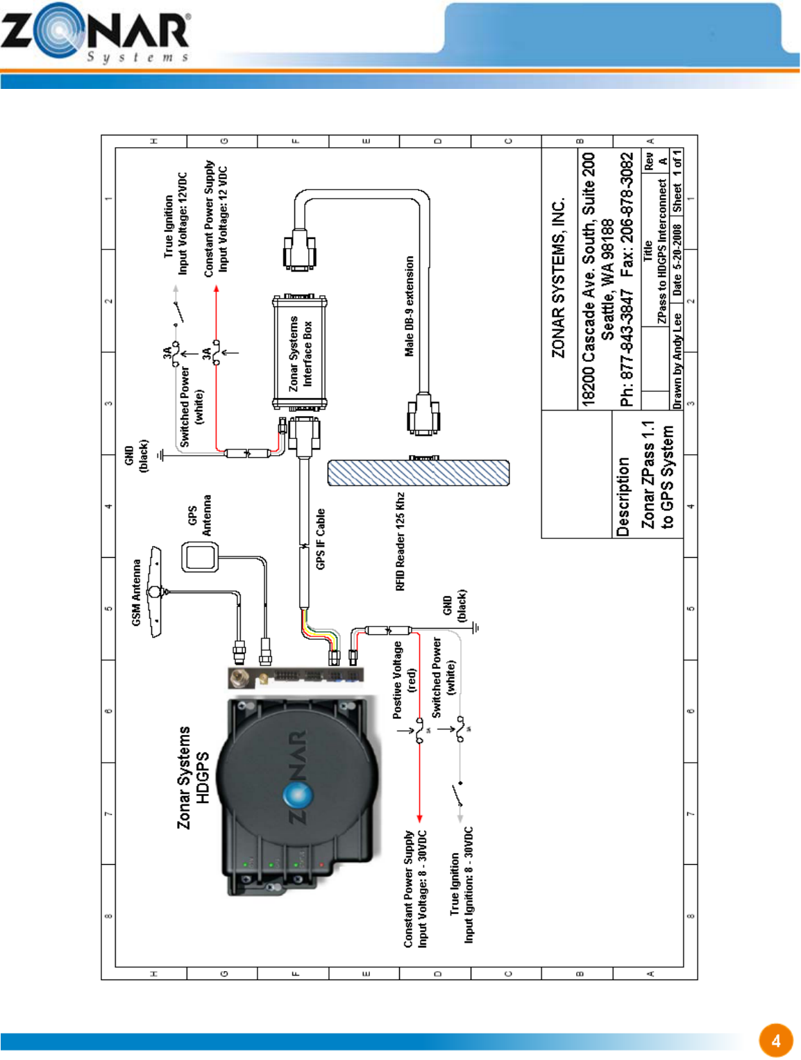
Schematic
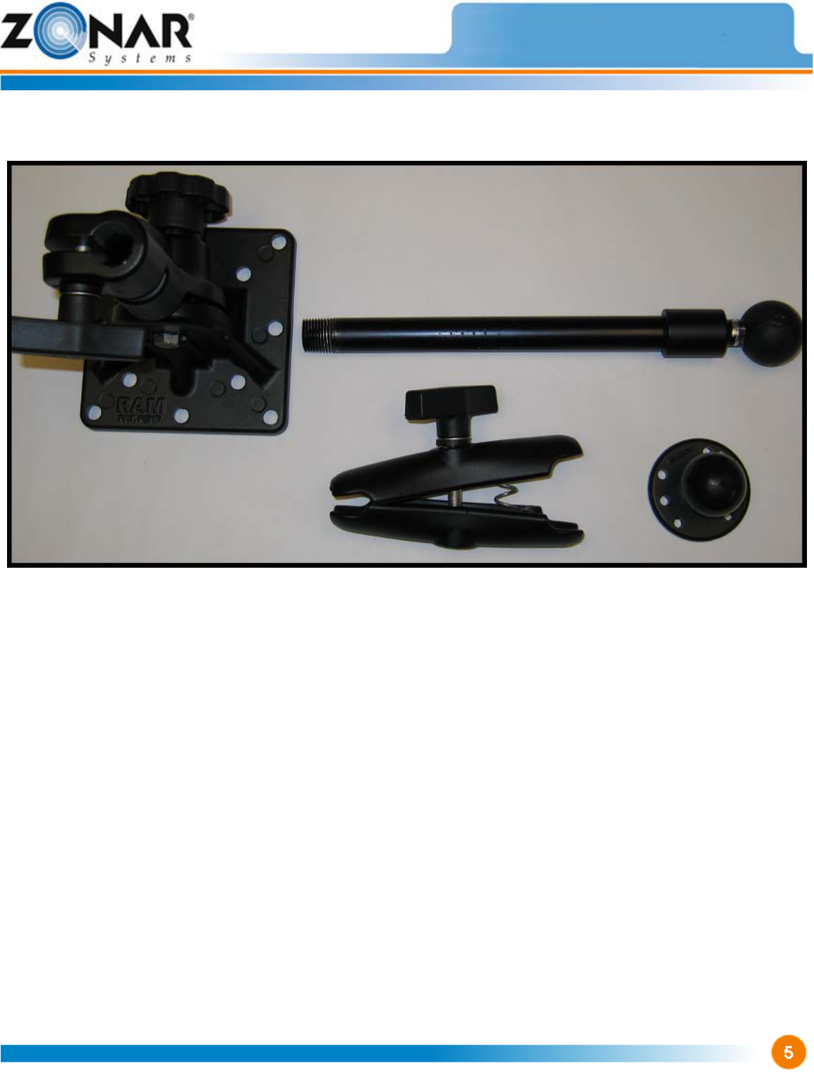
ZPassTM Mounting
The Mounting System:
1) Holds the ZPassTM Reader
2) Is generally mounted near passenger entrance/exit
Note: Verify placement acceptability with state
DOT/Law Enforcement prior to installation.
3) Ensure location of installed ZPassTM does not block
driver view and interfere with vehicle operation and
loading/unloading of passengers (e.g. snag coats,
book bags, etc.)
Customer Supplied:
- 4 mounting bolts and lock
washers (Ram Mount base to
vehicle)
Zonar Supplied:
- 4 black mounting screws (Zpass
mounting ball – Pictured lower
right)
6) The White wire must be connected to a
power source that is active only when
Zpass reader is required to read Zpass
RFID cards.
Example: Door-Open (regardless of
motor power or ignition key switch
position)
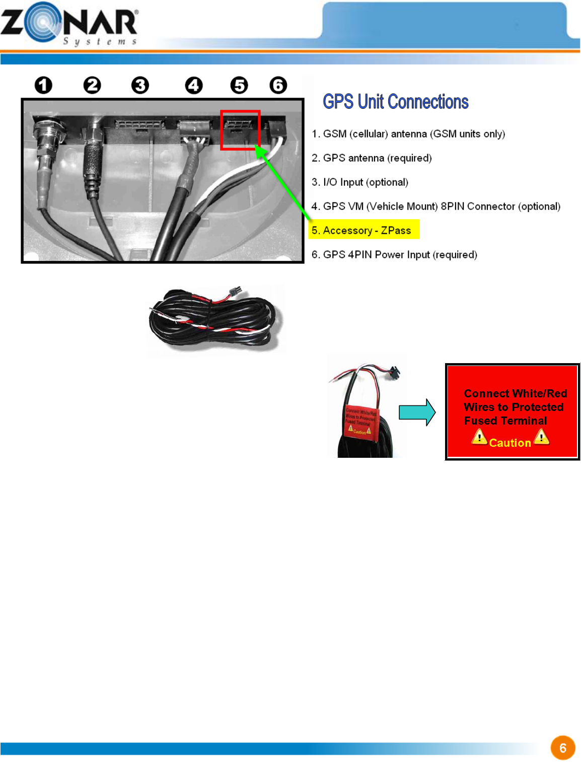
Cables
ZPassTM Power Cable
1) Follow all General Guidelines as specified on page 4.
2) All power leads (Red and White leads, GPS-Power
Cable) must be connected to the vehicles protected
circuitry (e.g. fuse panel, circuit breaker panel,
protected circuits). Never electrically connect Zonar
equipment to unprotected circuits. (e.g. directly to
battery)
3) It is also required that all power leads (Red and White
leads, GPS-Power Cable) be protected with a 3 to 5
amp fuse and inline fuse holder (included) for optimal
system protection.
4) Vehicles equipped with “noise kill” switches (late model
school buses) – Do Not wire any Zonar equipment to
the “noise kill” circuitry.
5) Power Bundle wiring – 4 Pin, 3 wires
a. Red – Constant DC (+8VDC - +30VDC, dependent
on system type)
b. Black – Ground
c. White – Switched Power
i. Zpass reader operation desired: +8VDC -
+30VDC, dependent on system type
ii Zpass operation not needed / desired: 0VDC. Do
not connect to constant hot – battery will drain
during long periods of vehicle inactivity)