Zoom Telephonics 1067WL Zoom X6v ADSL/2/2+ VoIP Wireless-G Router User Manual X6v UserGuide draft version
Zoom Telephonics Inc Zoom X6v ADSL/2/2+ VoIP Wireless-G Router X6v UserGuide draft version
UserManual.wiki
>
Zoom Telephonics
>
1067WL User Manual
Users Manual
Navigation menu
Upload a User Manual
Namespaces
Wiki Guide
HTML
PDF
Info
Views
User Manual
Discussion / Help
Navigation
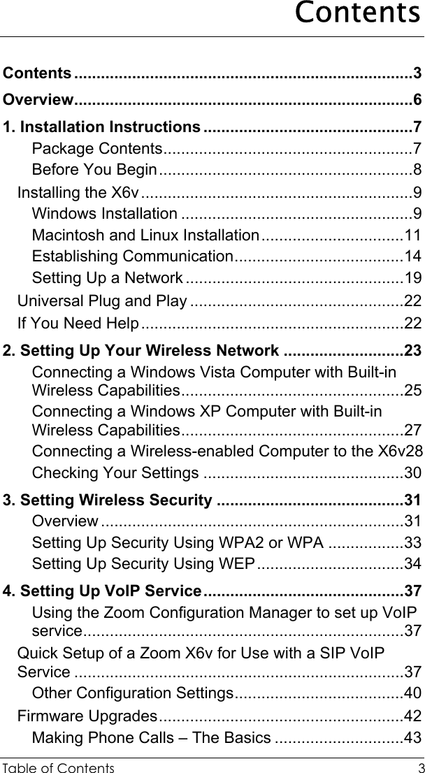
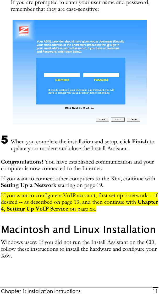

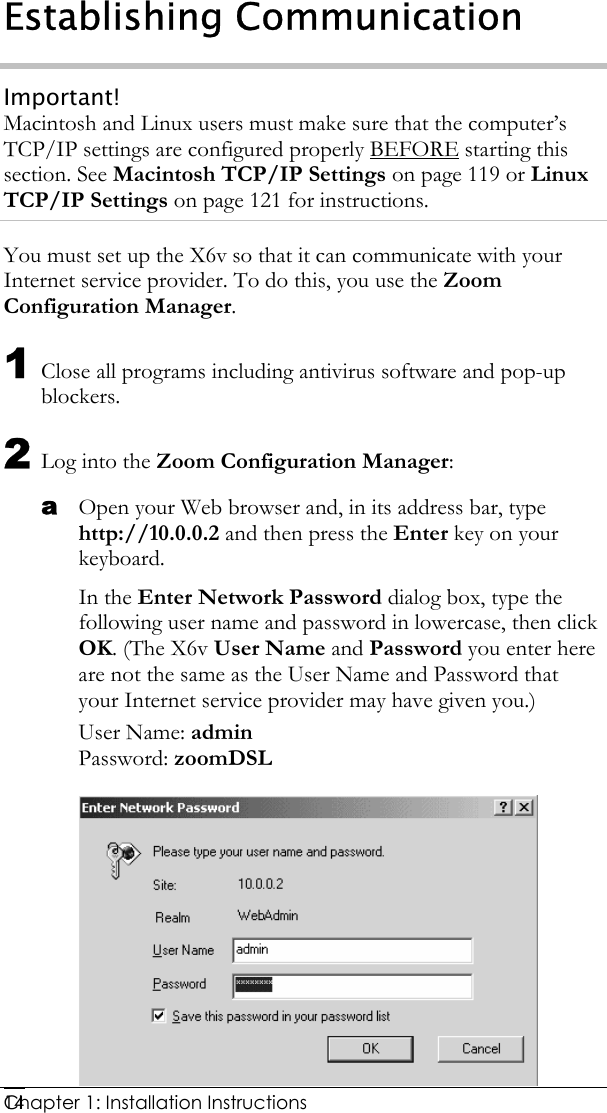
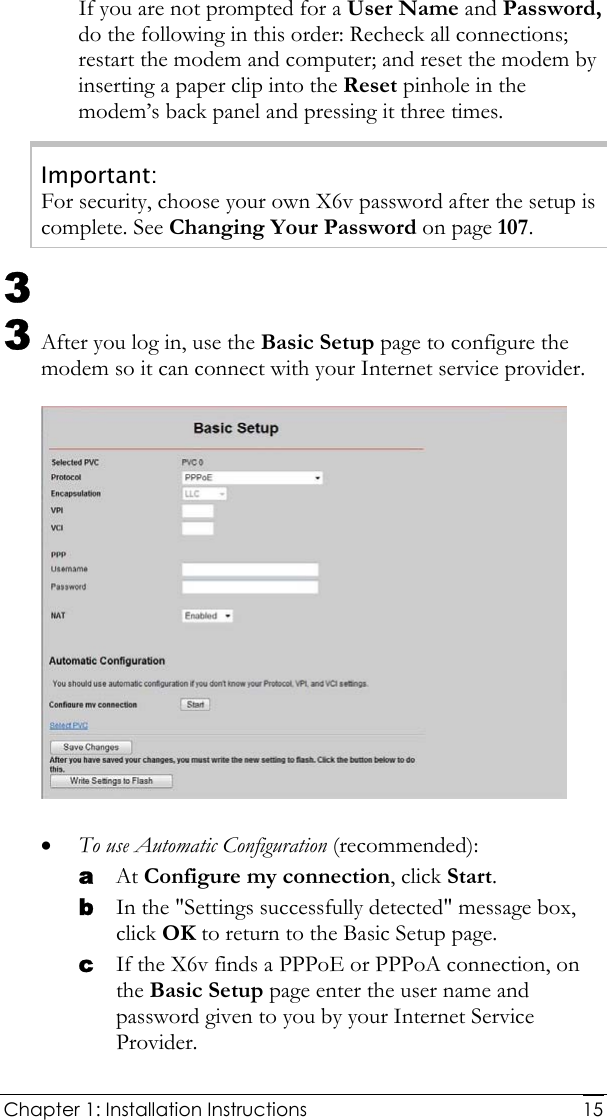
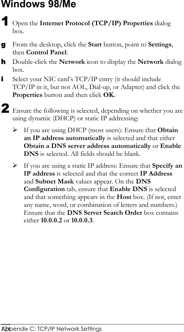
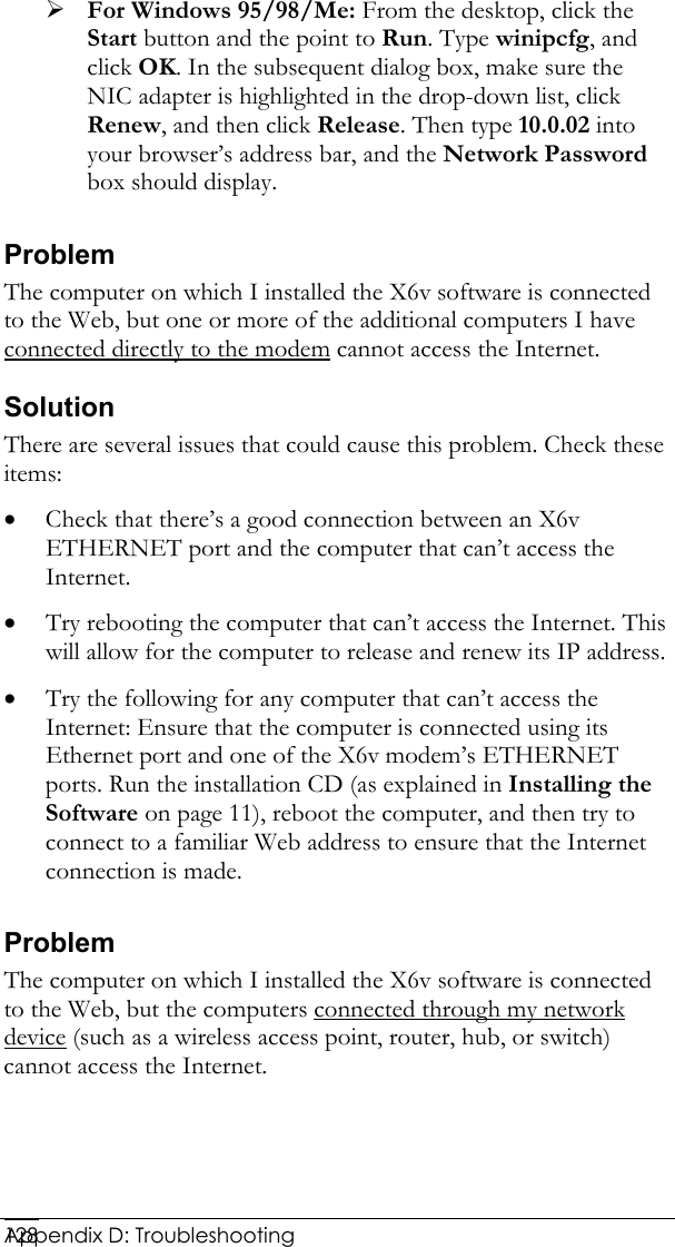
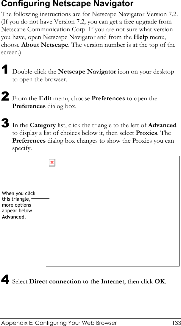
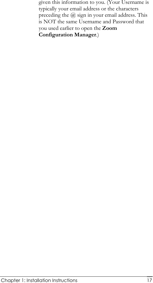
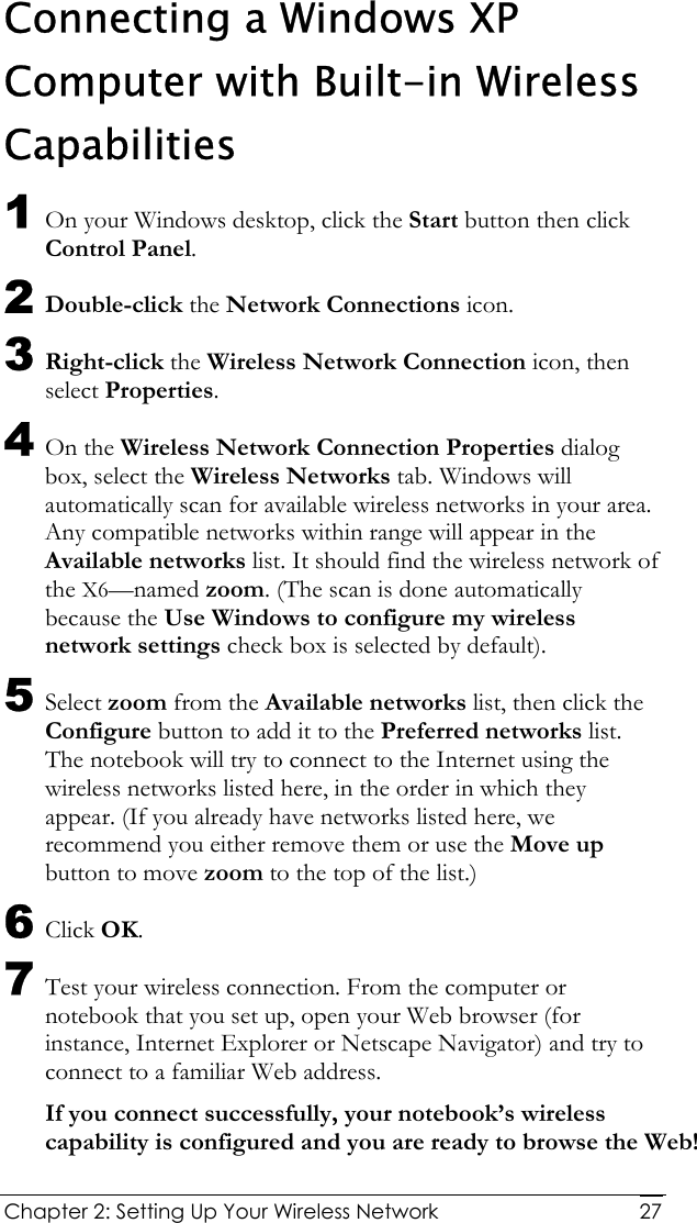
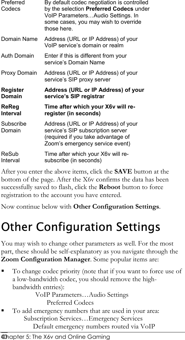
![Chapter 1: Installation Instructions 16If the X6v finds a 1483 Bridged or 1483 Routed connection, you have the option of using either dynamic or static IP addressing. Depending on your situation, select the appropriate option button: − [MOST USERS] Ensure that Obtain an IP address Automatically is selected if you are using Dynamic Host Configuration Protocol (also known as DHCP or dynamic IP addressing). This option is selected by default because most Internet service providers use DHCP. − Select Use the following IP Address only if you are using a static IP address. (You should know if you are using static IP addressing. There is typically an extra charge for a static IP address and you usually have to make special arrangements with your Internet service provider to get one.) Then enter the IP Address, Subnet Mask, Default Gateway, and DNS that you plan to use. Click the Save Changes button, then click the Write Settings to Flash button. • To configure your settings manually if Automatic Configuration does not work, follow these instructions: a On the Basic Setup page, enter your Protocol, Encapsulation, VPI, and VCI settings in the appropriate boxes. Your service provider should supply these values. If you do not know these settings, refer to the tables starting on page 111. b NAT (Network Address Translation) is Enabled by default. This feature lets multiple users access the Internet sharing a single IP address. Enabled is typically the right setting. Select Disable in the unlikely event that you want to assign different public IP addresses to each network user. c Depending on the Protocol setting you selected the bottom half of the page will change so that you can enter additional information. If you selected PPPoA or PPPoE, enter your DSL Username and Password in the appropriate boxes. Your Internet service provider should have](https://usermanual.wiki/Zoom-Telephonics/1067WL/User-Guide-919966-Page-16.png)
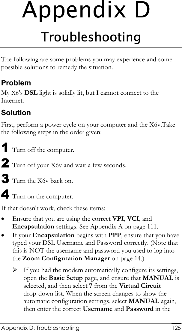
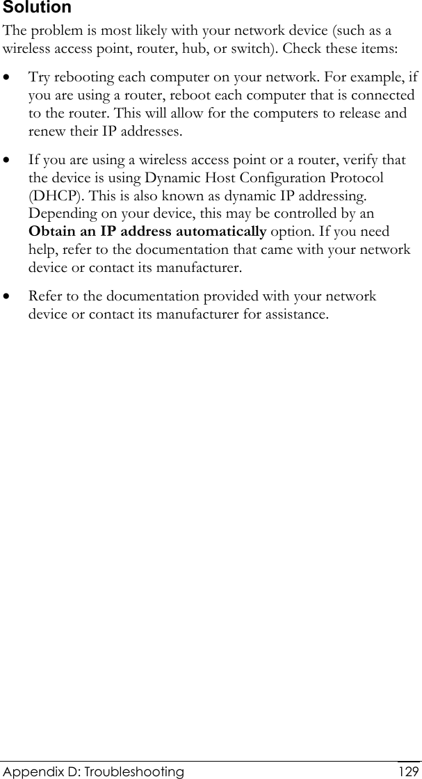
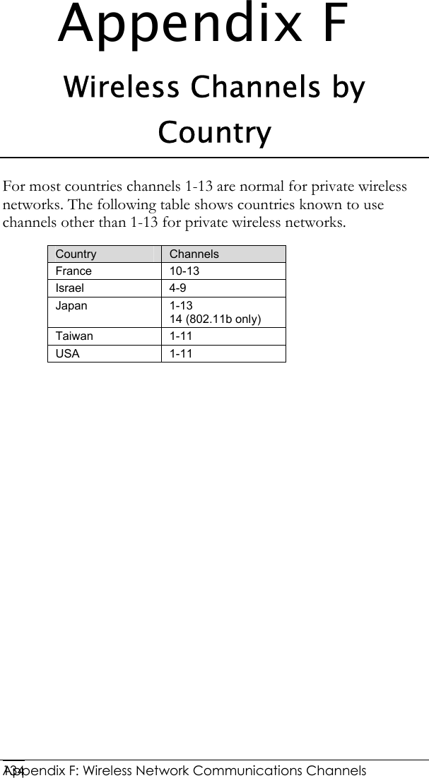
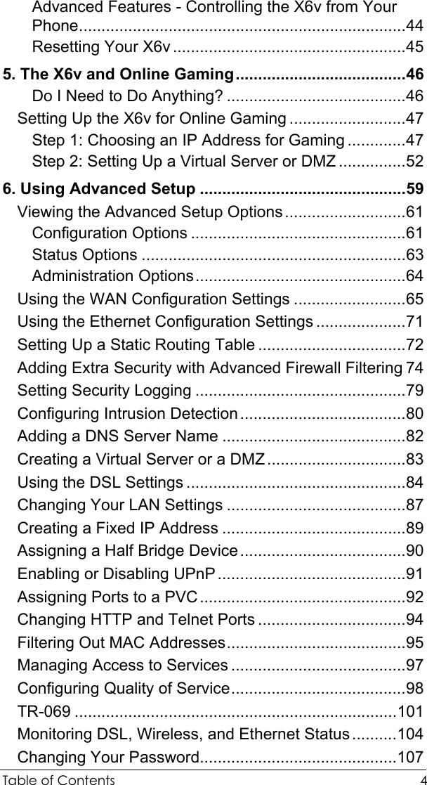
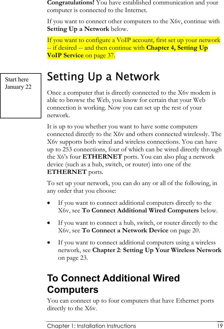
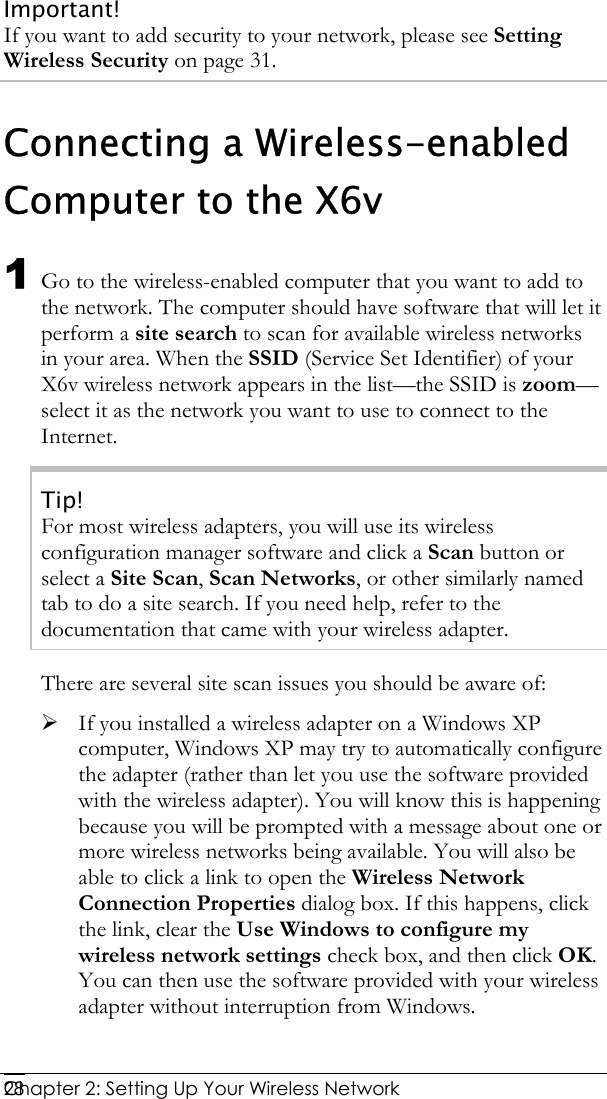
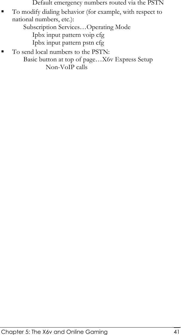
![Chapter 1: Installation Instructions 18 If you selected 1483 Bridged or 1483 Routed, you have the option of using either dynamic or static IP addressing. Depending on your situation, select the appropriate option button: − [MOST USERS] Ensure that Obtain an IP address Automatically is selected if you are using Dynamic Host Configuration Protocol (also known as DHCP or dynamic IP addressing). This option is selected by default because most Internet service providers use DHCP. − Select Use the following IP Address only if you are using a static IP address. (You should know if you are using static IP addressing. There is typically an extra charge for a static IP address and you usually have to make special arrangements with your Internet service provider to get one.) Then enter the IP Address, Subnet Mask, Default Gateway, and DNS that you plan to use. Click the Save Changes button, then click the Write Settings to Flash button. 4 Verify that you Internet connection is working. Open your Web browser (for instance, Internet Explorer or Netscape Navigator) and try to connect to a familiar Web address. If you connect successfully, you are ready to set up the rest of your network. (If you do not connect, see Appendix D on page 125). Tip! If you configured the X6v using a notebook computer, you can keep it plugged in or you can disconnect it from the unit’s ETHERNET port. As long as the X6v remains plugged into an DSL wall jack and a power source, the X6v can function as a stand-alone device. You can then make the notebook part of your wireless network.](https://usermanual.wiki/Zoom-Telephonics/1067WL/User-Guide-919966-Page-18.png)
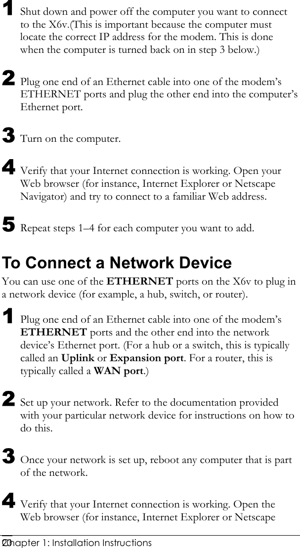
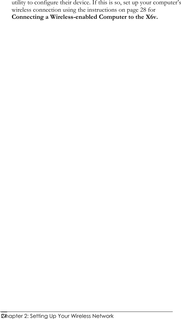
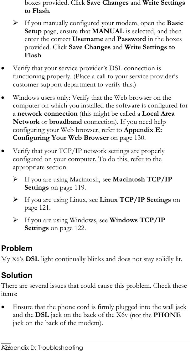
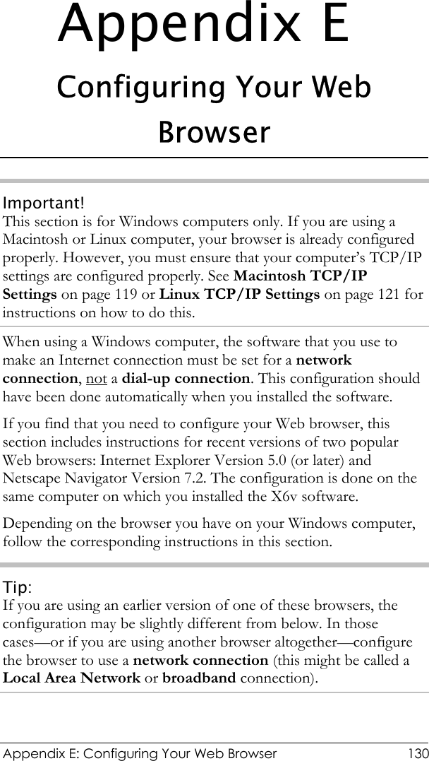
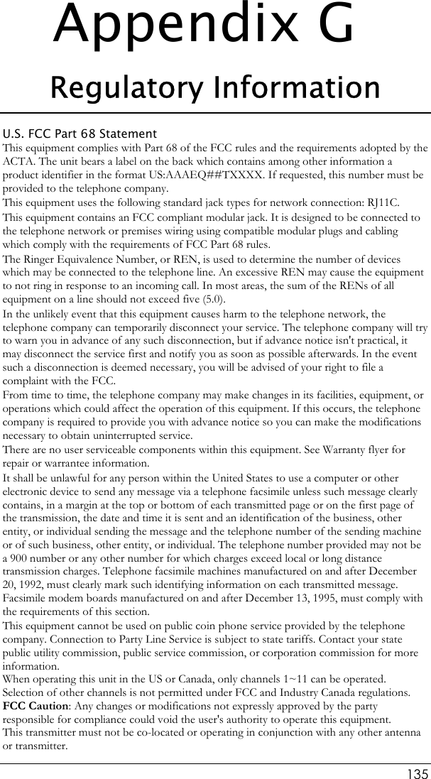
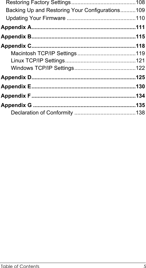
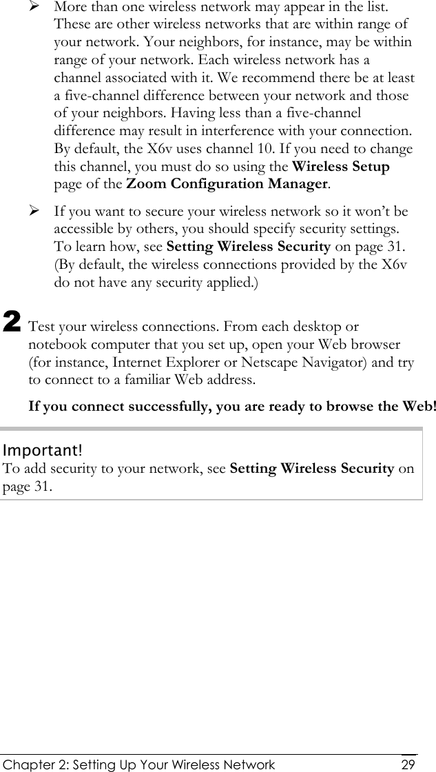
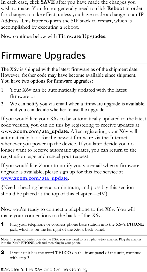
![Chapter 2: Setting Up Your Wireless Network 26computer and the X6v as described in the Troubleshooting Tips on page 125. 3 In the Successfully connected to [desired network] dialog box, you have three options. You can: • Select Save the network and Start this connection automatically if you always want to connect to the same network. Then click Close. The next time you start your computer you will automatically connect to the selected network. • Select Save the network and clear the Start this connection automatically check box if you don't want to automatically connect to this network every time you start your computer but you will want to connect in the future. Click Close to display the Select a location . . . dialog box where you choose a location. Windows Vista automatically applies the correct network security settings. If the User Account Control dialog box appears, click Continue. • Click Close to complete the connection procedure. Select this option if you are connecting to this network only one time. To disconnect from the current network: 1 From the Start menu, select Connect to. 2 In the Disconnect or Connect to another network dialog box, select the current network and click Disconnect. 3 In the Are You Sure? message box, click Disconnect again. 4 In the next dialog box, you can connect to another network or click Close to complete the disconnect procedure.](https://usermanual.wiki/Zoom-Telephonics/1067WL/User-Guide-919966-Page-26.png)
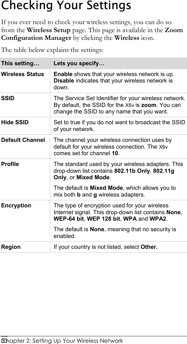

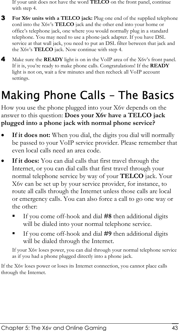

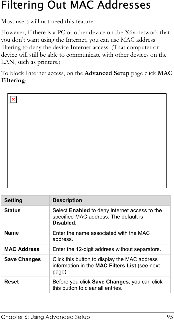
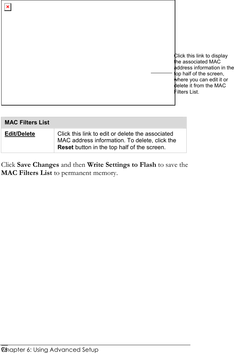
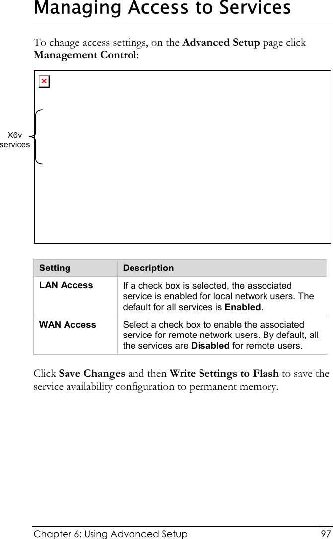
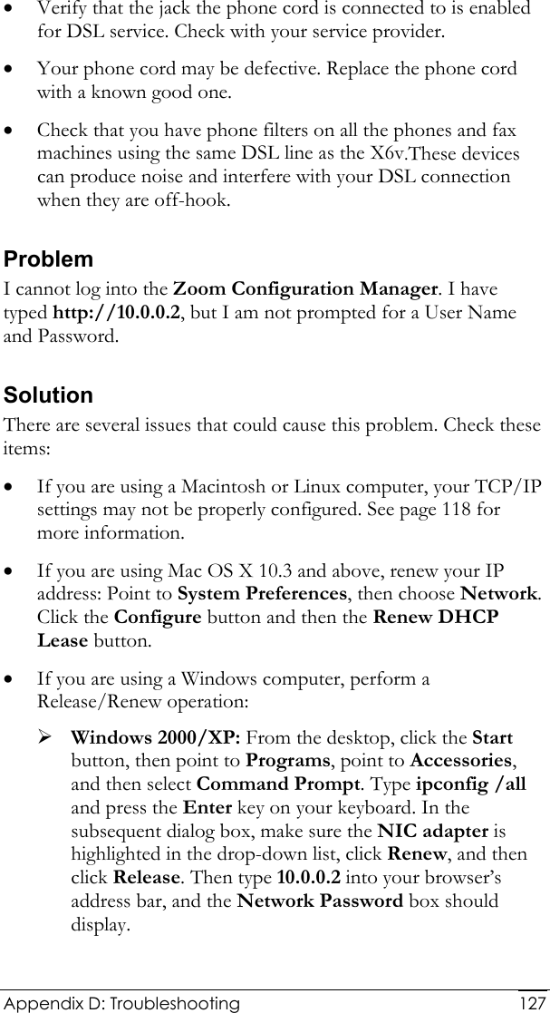
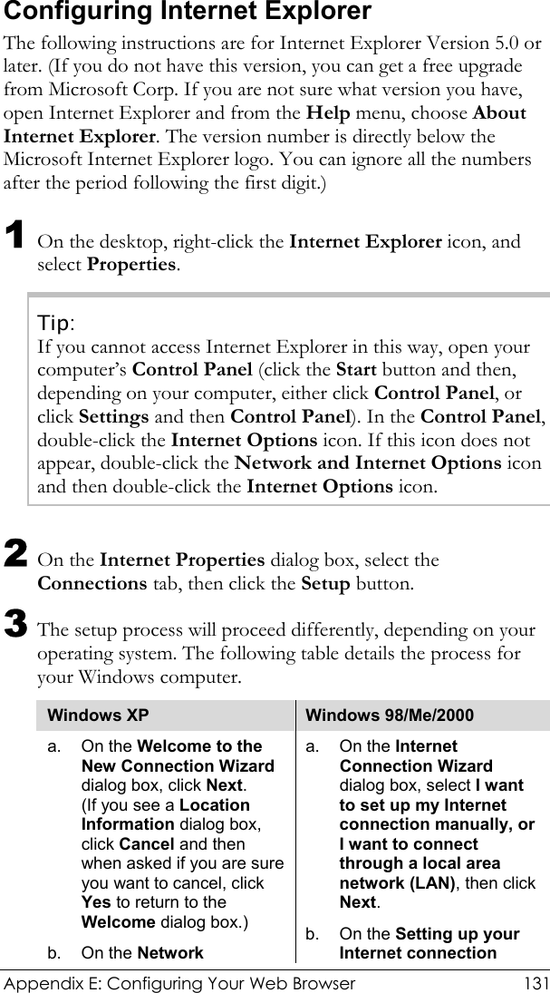
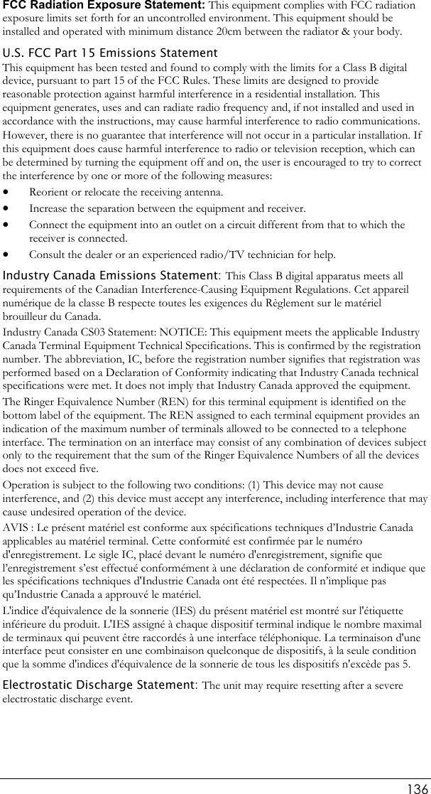
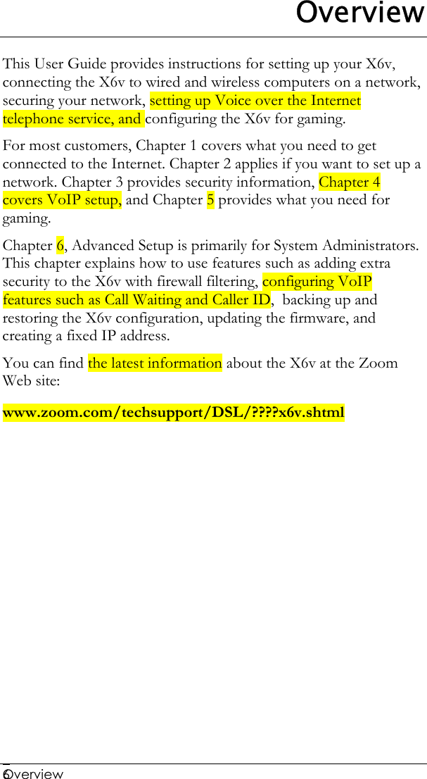
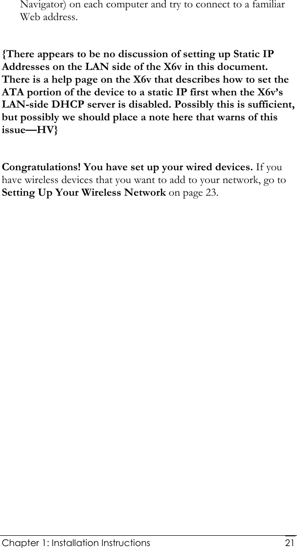
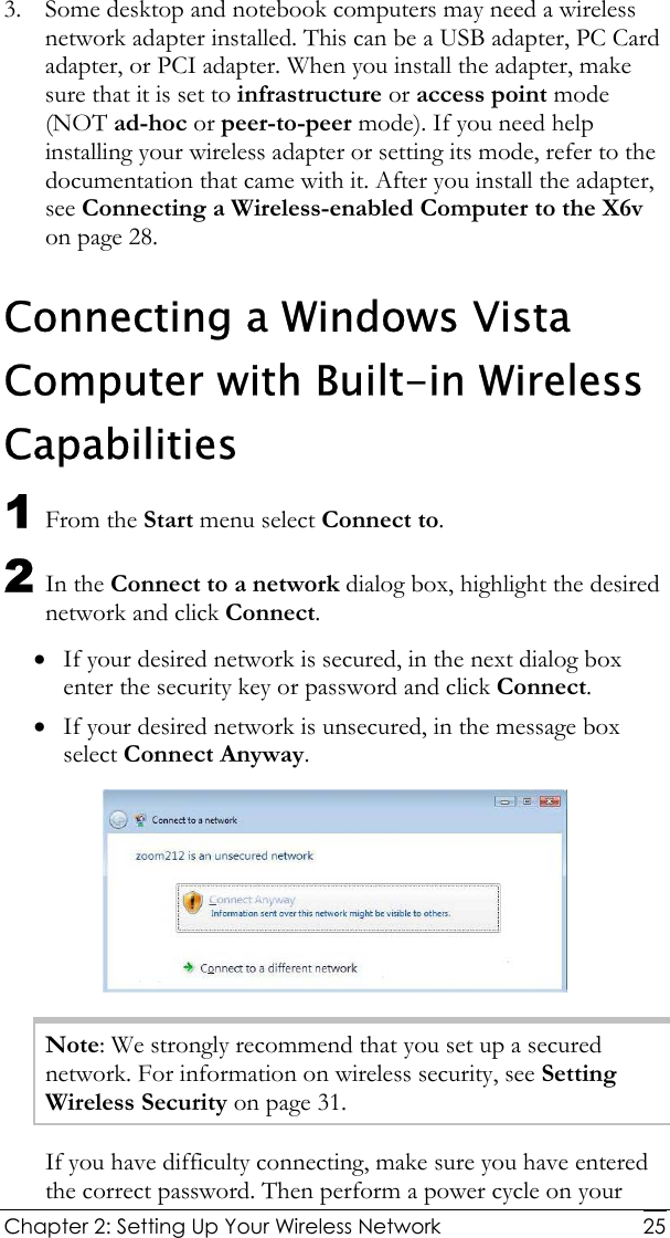
![Chapter 6: Using Advanced Setup 94Changing HTTP and Telnet Ports This feature lets you change the default X6v ports for Internet and Telnet traffic. If, for example, you are running another Internet server on the network and that server is using Port 80, you need to assign a different port to the X6v to avoid a conflict. To assign Internet (HTTP) or Telnet ports, on the Advanced Setup page click Port Settings: Setting Description HTTP Port Enter a port number. (The default is 80.) Telnet Port Enter a port number. (The default is 23.) Click Save Changes and then Write Settings to Flash to save the new port settings to permanent memory. Reboot your PC to make the settings active. When the new port settings are saved, network users who want to access the X6v via the Internet must add a colon [ : ] plus the new port number after the X6’s IP address. For example, in their browser’s address bar, users would enter 10.0.0.2:61101, where 61101 is the new Internet port. To access the X6v via Telnet, users would type telnet[space]10.0.0.2[space]61102, where 61102 is the new port.](https://usermanual.wiki/Zoom-Telephonics/1067WL/User-Guide-919966-Page-94.png)