ZyXEL Communications C3000Z WiFi-N VDSL2 4-port Combo WAN CPE User Manual
ZyXEL Communications Corporation WiFi-N VDSL2 4-port Combo WAN CPE
User Manual.pdf
Quick Start Guide
www.zyxel.com
C3000Z
WiFi-N/AC 2.4G 3x3 /5G 4X4 VDSL2 4-port
Bonding Combo WAN IAD
Version CZD001-4.16.002.0
Edition 1, 04/2017
Default Login Details
LAN IP Address http://192.168.0.1
User Name admin
Password Check the device label
Copyright © 2017 ZYXEL Communications Corporation
Quick Start Guide
2
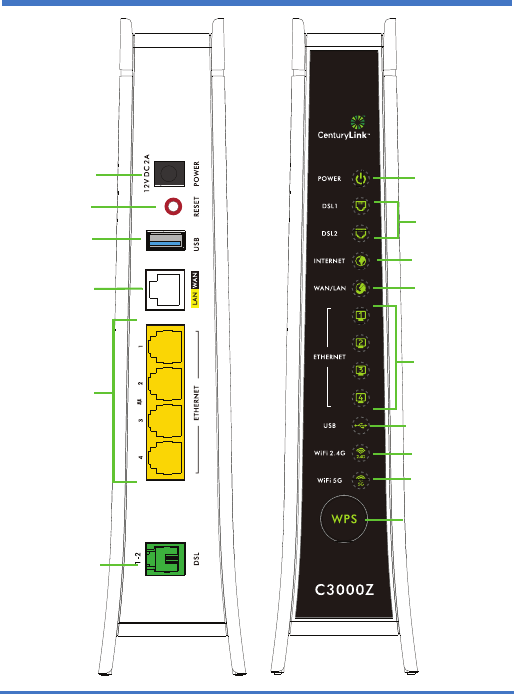
Device Panels
POWER
DSL
INTERNET
ETHERNET
USB SLOT
POWER
RESET
DSL PORT
USB
ETHERNET 1-4
WIFI 2.4G
WAN/LAN
LAN/WAN
PORTS 1-4
WPS
BUTTON
PORT
WIFI 5G

3
Overview
The Device is a VDSL2 bonding integrated access device (IAD) with a
four-port built-in Ethernet switch and IEEE 802.11ac wireless. The
Device allows wired and wireless clients to safely access the Internet.
Additionally, the Device includes a Gigabit Ethernet LAN port that can
also serve as a WAN connection to support a dual WAN function. The
USB port allows you to connect a USB memory stick or USB hard drive
for storing or sharing files through the network.
Requirements
Make sure you have the following things before you start.
• Internet access - account information provided by your ISP, such as
user name, password, and so on.
• Internet Explorer 8.0 and later versions, with JavaScript enabled, or
Mozilla Firefox 14 and later versions.
44
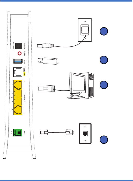
Hardware Connections
1
2
3
4

5
1. Use a telephone cable to connect your Device’s DSL port to a
telephone jack (or the DSL or modem jack on a splitter if you have
one).
2. ETHERNET: Use an Ethernet cable to connect a computer to a LAN
port for initial configuration and/or Internet access.
3. USB: You can connect a USB memory stick or a USB hard drive for
file sharing. The Device automatically detects the USB device.
Alternatively, use a USB cable (not provided) to connect a USB
printer to this port.
4. POWER: Use the provided power adaptor to connect the POWER
socket to an appropriate power source. Make sure the power at the
outlet is on. Look at the lights on the front panel.
•The POWER light blinks while your Device starts up and then stays
solid green once it is ready.
•The DSL lights are solid green after your Device has a DSL
connection.
•The INTERNET light turns on when the Device is able to access the
Internet and blinks when the Device is sending or receiving data.
•The WAN/LAN light is on if the WAN/LAN port is properly connected
and blinks when there is traffic.
• Each ETHERNET light is on if the corresponding LAN port is
properly connected and blinks when there is traffic.
•The USB light turns on when there is a USB printer or memory
device is connected to the Device and blinks when transmitting data.
•The WiFi 2.4G light is green when the wireless LAN is ready and
blinks when there is traffic.
•The WiFi 5G light is green when the wireless LAN is ready and
blinks when there is traffic.
•The WPS light is green when WPS is enabled and blinks amber
while WPS is in process.
If the lights do not come on, check your connections and inspect your cables
for damage. If the lights are still off, contact technical support.

66
Internet Connection Setup
Your Device can automatically detect and configure your Internet
connection once the hardware is connected properly.
Automatic Connection
1. Open your web browser to a website. Wait while your Device tries to
detect your DSL connection to your ISP. This may take a few
minutes.
2. After it detects the connection, the DSL lights show amber on your
Device and the INTERNET light comes on when the Internet is ready
for you to use. If you have a PPPoE connection, you will have to
enter the user name and password provided by your ISP.
3. Go to Set Up a Wireless Network if you wish to configure your
wireless settings.
4. If the automatic connection is not successful, check your connections
and restart the Device. Also, make sure you have entered the user
name and password correctly. If you still cannot access the Internet,
follow the steps in the next section to manually configure the Internet
connection.
Manual Connection
You can also manually log into the Device’s Web Configurator and
configure the Internet connection.
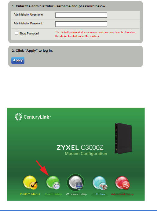
1. In your browser, if the Device does not automatically re-direct you to
the login screen, go to http://192.168.0.1.
7
2. Enter the default user name admin and password (see the Device’s
label). Click Apply.
If the login screen does not open, make sure you allow web browser pop-up
windows, JavaScripts and Java permissions. Your computer should be also
set to get an IP address automatically from a DHCP server.
3. The main screen appears. Click Quick Setup to configure the
Device’s Internet access.
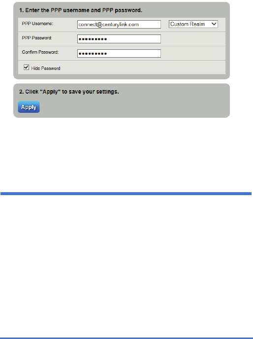
88
4. Enter the user name and password provided by your ISP. Click Apply
to finish the configuration.
5. The DSL lights are green on your Device and the INTERNET light
comes on when the Internet is ready for you to use. If you still cannot
access the Internet, contact your ISP.
Set Up a Wireless Network
You can set up a wireless network using the following methods:
Using Wireless Protected Setup (WPS)
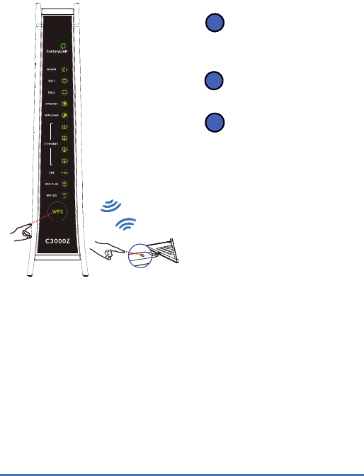
Press the WPS button on the Device’s front panel for more than 5
seconds to turn the WPS function on.
9
Follow these steps to add a WPS-enabled device to the wireless
network using the WPS button.
Set Up a Wireless Network Manually
The wireless LAN on your Device is enabled by default. To add a
wireless client to the network, use the settings found on the bottom panel
of your Device.
Configure wireless devices that you want to connect to the wireless
network to use the same wireless settings as the Device.
The default wireless settings vary for each Device. Refer to the label of
your Device and use the provided information.
Place the devices you
want to connect near one
another.
Press the WPS button on
the Device.
Press the WPS button on
a compatible device
within 2 minutes of
pressing the button on
the Device.
The WPS light on the
Device blinks amber
when connection is in
progress and is solid
green when connected.
WPS
1
2
3
1010
Wall Mounting
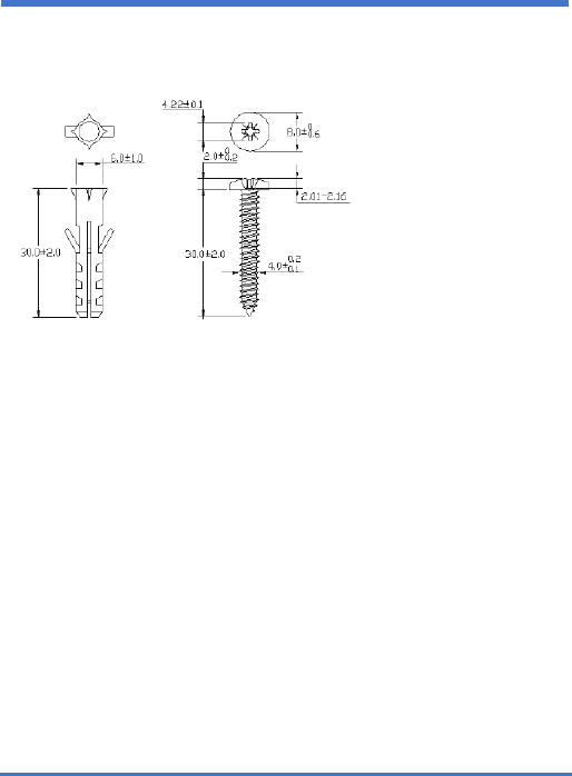
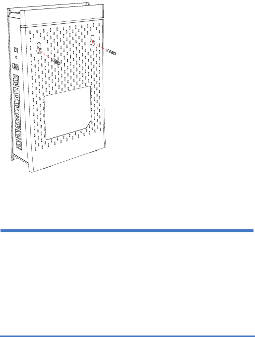
The following are dimensions of a screw anchor and M4 tap screw used
for wall mounting. All measurements are in millimeters (mm).
1. Locate a high position on a wall that is free of obstructions. Use a
sturdy wall.
2. For a concrete or brick wall find a drill bit with the same diameter as
the screw anchors. If you do not need the screw anchors, find a drill
bit slightly smaller in diameter than the included screws.
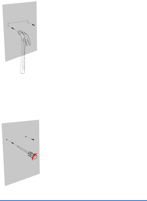
3. Drill the two screw holes in the wall. Make sure the distance between
the centers of the holes is the same as the wall-mount holes.
Be careful to avoid damaging pipes or cables located inside the
wall when drilling holes for the screws.
11
4. Use a hammer to tap the screw anchors into the holes.
5. Insert and slowly screw the screws into the anchors (or the holes if
you are not using anchors). Make sure the screws are snugly
fastened to the wall. They need to hold the weight of the Device with
the connection cables. Do not screw the screws all the way into the
wall. Leave a small gap of about 0.5 cm between the heads of the
screws and the wall.
94.5mm
1212
6. Align the holes on the back of the Device with the screws on the wall.
Hang the Device on the screws.
Federal Communications Commission
(FCC):
This device complies with part 15 of the FCC Rules. Operation is subject to the
following two conditions:
(1) This device may not cause harmful interference, and
(2) This device must accept any interference received, including interference that
may cause undesired operation.
NOTE: This equipment has been tested and found to comply with the limits for a
Class B digital device, pursuant to part 15 of the FCC Rules. These limits are
designed to provide reasonable protection against harmful interference in a
residential installation. This equipment generates, uses and can radiate radio

13
frequency energy and, if not installed and used in accordance with the instructions,
may cause harmful interference to radio communications. However, there is no
guarantee that interference will not occur in a particular installation. If this
equipment does cause harmful interference to radio or television reception, which
can be determined by turning the equipment off and on, the user is encouraged to
try to correct the interference by one or more of the following measures:
• Reorient or relocate the receiving antenna.
• Increase the separation between the equipment and receiver.
• Connect the equipment into an outlet on a circuit different from that to which
the receiver is connected.
• Consult the dealer or an experienced radio/TV technician for help.
Caution
Changes or modifications not expressly approved by the party responsible for
compliance could void the user's authority to operate the equipment.
For product available in the USA/Canada market, only channel 1~11 can be
operated. Selection of other channels is not possible.
This device and it's antenna(s) must not be co-located or operating in conjunction
with any other antenna or transmitter except in accordance with FCC multi-
transmitter product procedures.
IMPORTANT NOTE:
Radiation Exposure Statement:
This equipment complies with FCC RF radiation exposure limits set forth for an
uncontrolled environment. This equipment should be installed and operated with
minimum distance 40 cm between the radiator and your body.
FCC REQUIREMENTS:
This equipment complies with TIA-968-B of FCC Rules. On the bass unit of this
equipment is a label that contains, among other information, the FCC Registration
Number and Ringer Equivalence Number (REN) for this equipment. IF
REQUESTED, THIS INFORMATION MUST BE GIVEN TO THE TELEPHONE
COMPANY.
The REN is useful to determine the quantity of devices you may connect to your
telephone line and still have all of those devices ring when your telephone number
is called. In most, but not all areas, the sum of the REN of all devices connected to
one line should not exceed five (5.0). To be certain of the number of devices you
may connect to you line, as determined by the REN, you should contact your local
telephone company to determine the maximum REN for your calling area.

1414
If your equipment causes harm to the telephone network, the telephone company
may discontinue your service temporarily. If possible, they will notify you in
advance. But if advance notice is not practical, you will be notified as soon as
possible. You will be informed of your right to file a complaint with the FCC. Your
telephone company may make changes in it is facilities, equipment, operations or
procedures that could affect the proper functioning of your equipment. If they do,
you will be notified in advance to give you an opportunity to maintain uninterrupted
telephone service.
A Plug and jack used to connect this equipment to the premises wiring and
telephone network must comply with the applicable FCC Part 68 rules and
requirements adopted by the ACTA. A compliant telephone cord and modular plug
is provided with this product. It is designed to be connected to a compatible
modular jack that is also compliant. See installation instructions for details.
The telephone company may make changes in its facilities, equipment, operations
or procedures that could affect the operation of the equipment. If this happens, the
telephone company will provide advance notice in order for you to make necessary
modifications to maintain uninterrupted service.
This equipment could be repair by users, there is not any component can be
removed or changed.
Connection to party line service is subject to state tariffs. Contact the state public
utility commission, public service commission or corporation commission for
information.
If you experience trouble with this telephone equipment, please contact the
following address and phone number for information on obtaining service or
repairs.
The telephone company may ask that you disconnect this equipment from the
network until the problem has been corrected or until you are sure that the
equipment is not malfunctioning.
This equipment may not be used on coin service provided by the telephone
company. Connection to party lines is subject to state tariffs.
COMPANY: ZYXEL Communications Inc.
ADDRESS: 1130 N. Miller St., Anaheim CA, 92806 USA
TEL NO.: 714-6320882

15
Safety Warnings
• Do NOT use this product near water, for example, in a wet basement
or near a swimming pool.
• Do NOT expose your device to dampness, dust or corrosive liquids.
• Do NOT store things on the device.
• Do NOT install, use, or service this device during a thunderstorm.
There is a remote risk of electric shock from lightning.
• Connect ONLY suitable accessories to the device.
• Do NOT open the device or unit. Opening or removing covers can
expose you to dangerous high voltage points or other risks. ONLY
qualified service personnel should service or disassemble this device.
Please contact your vendor for further information.
• Make sure to connect the cables to the correct ports.
• Place connecting cables carefully so that no one will step on them or
stumble over them.
• Always disconnect all cables from this device before servicing or
disassembling.
• Use ONLY an appropriate power adaptor or cord for your device.
• Connect the power adaptor or cord to the right supply voltage (for
example, 110V AC in North America or 230V AC in Europe).
• Do NOT allow anything to rest on the power adaptor or cord and do
NOT place the product where anyone can walk on the power adaptor
or cord.
• Do NOT use the device if the power adaptor or cord is damaged as it
might cause electrocution.
• If the power adaptor or cord is damaged, remove it from the device
and the power source.
• Do NOT attempt to repair the power adaptor or cord. Contact your
local vendor to order a new one.
• Do not use the device outside, and make sure all the connections are
indoors. There is a remote risk of electric shock from lightning.
• Do NOT obstruct the device ventilation slots, as insufficient airflow
may harm your device.
• Use only No. 26 AWG (American Wire Gauge) or larger
telecommunication line cord.
• Antenna Warning! This device meets ETSI and FCC certification
requirements when using the included antenna(s). Only use the
included antenna(s).
• The RJ-45 jacks are not used for telephone line connection.
1616
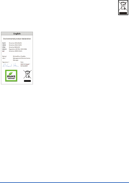
Your product is marked with this symbol, which is known as the
WEEE mark. WEEE stands for Waste Electronics and Electrical
Equipment. It means that used electrical and electronic products
should not be mixed with general waste. Used electrical and
electronic equipment should be treated separately.
EU Importer: ZYXEL Communications A/S | Generatorvej 8D, 2730 Herlev,
Denmark | http://www.ZYXEL.dk
US Importer: ZYXEL Communications, Inc | 1130 North Miller Street Anaheim, CA
92806-2001 | http://www.us.ZYXEL.com