ZyXEL Communications EMG1302R10A Wireless N300 4-port USB Ethernet Gateway User Manual EMG1302 R10A
ZyXEL Communications Corporation Wireless N300 4-port USB Ethernet Gateway EMG1302 R10A
UserManual.wiki
>
ZyXEL Communications
>
EMG1302R10A User Manual
EMG1312-R10A_UG
Navigation menu
Upload a User Manual
Namespaces
Wiki Guide
HTML
PDF
Info
Views
User Manual
Discussion / Help
Navigation
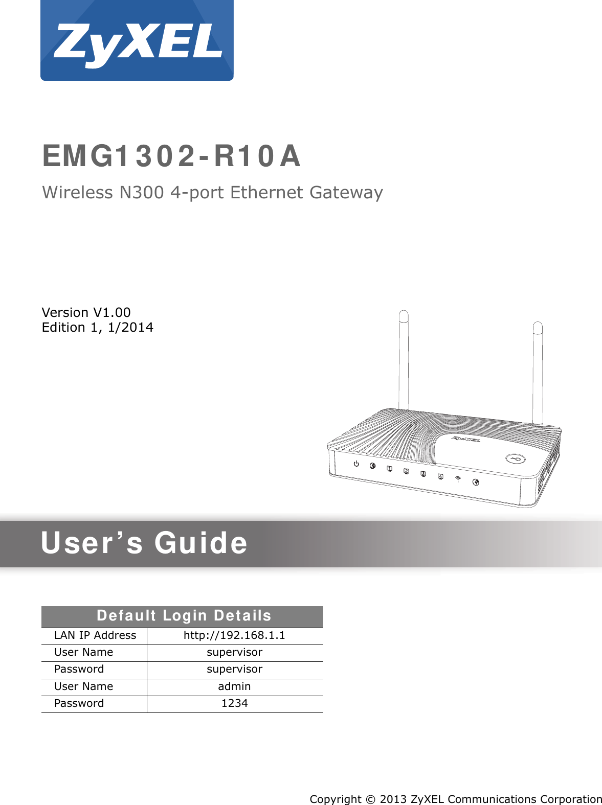


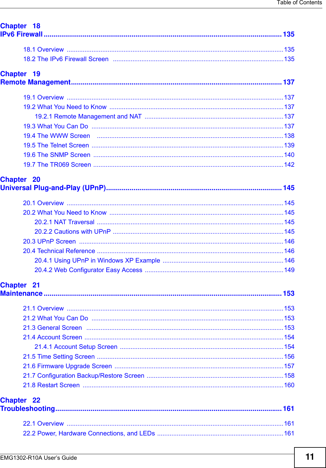
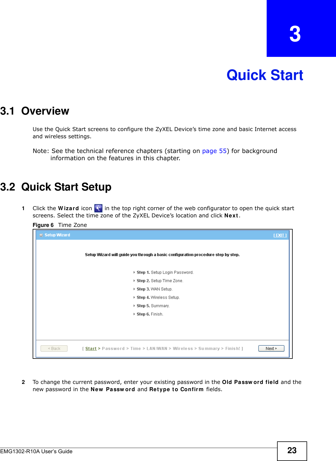
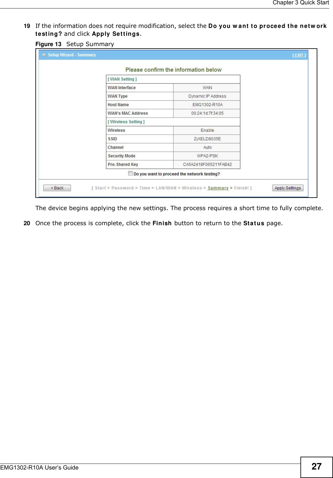


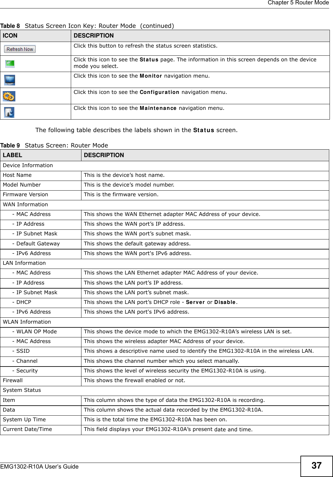

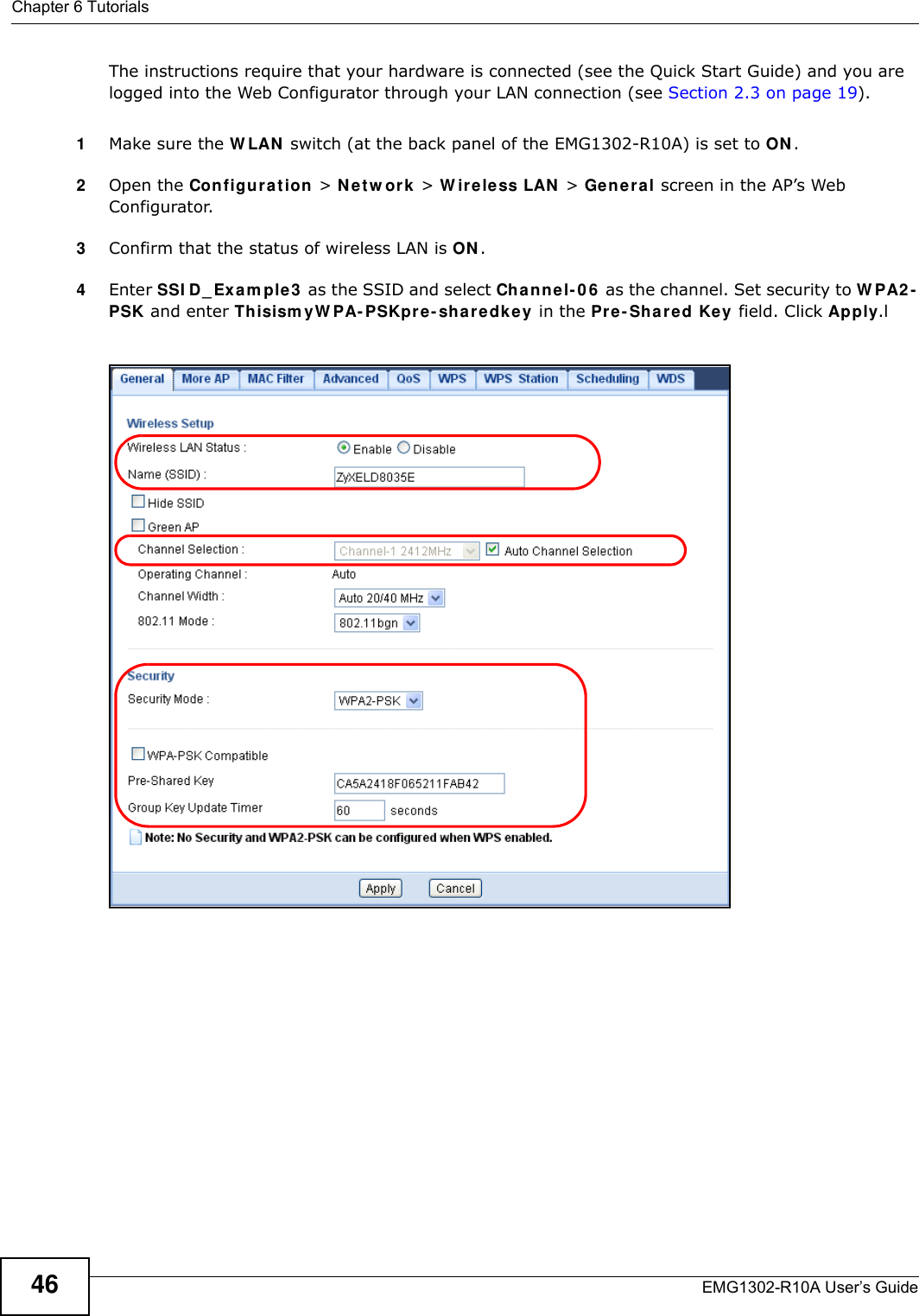
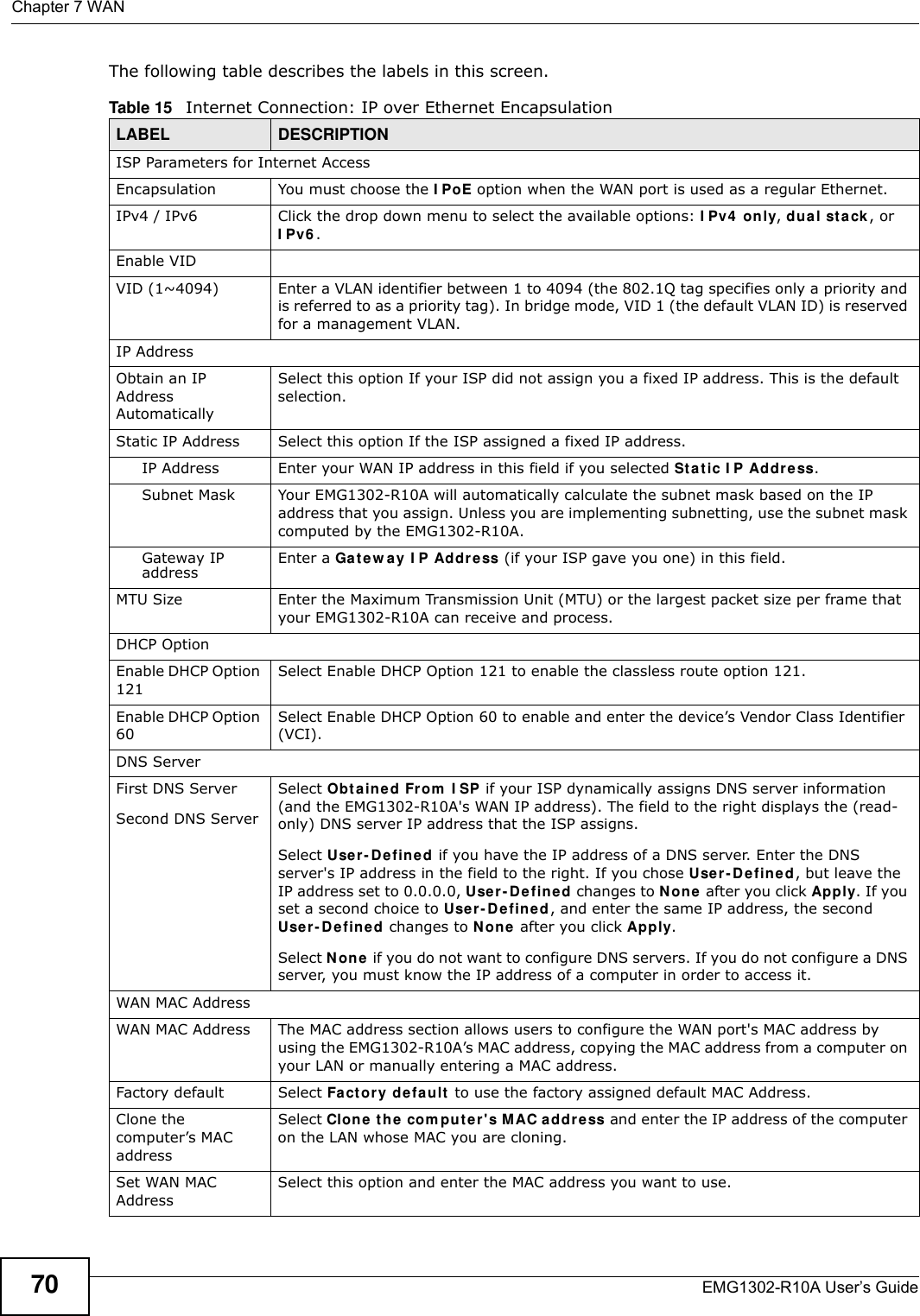

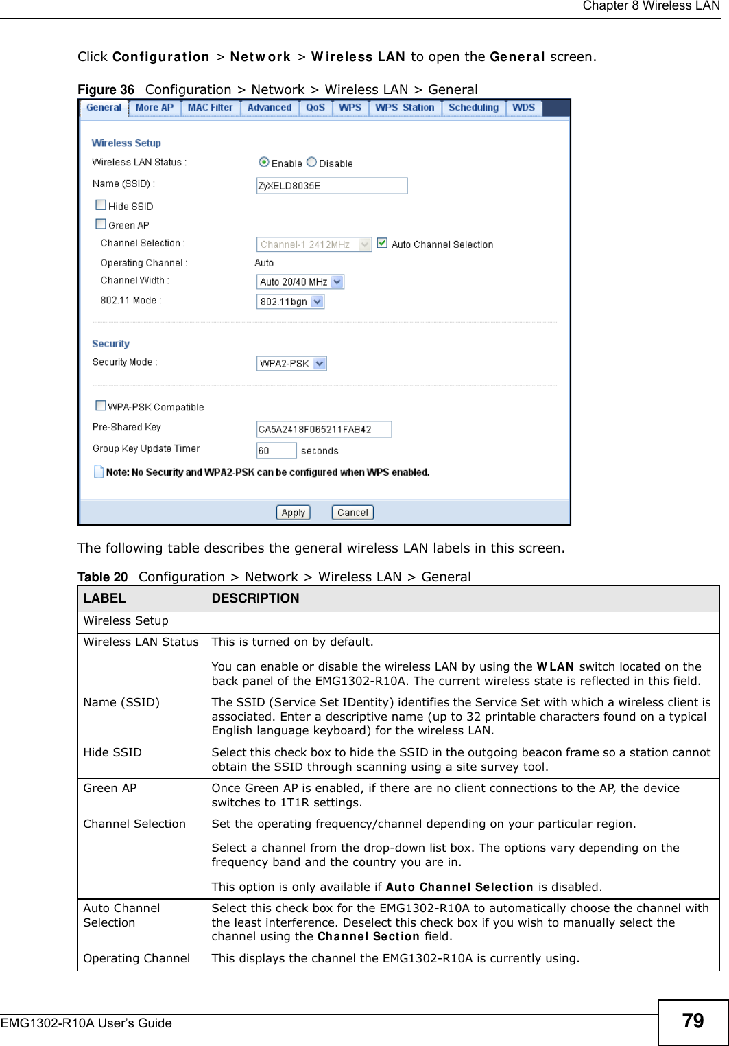
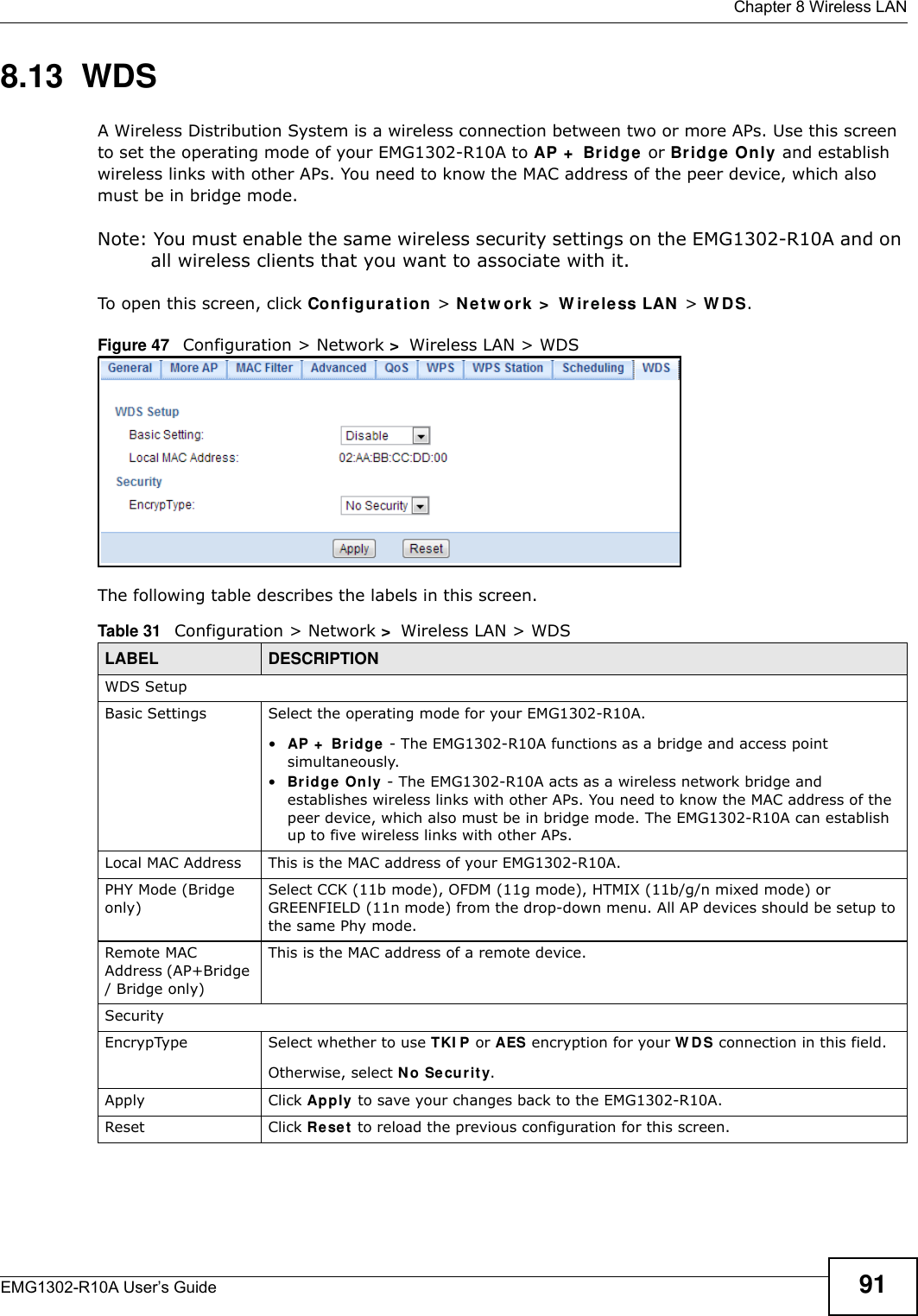
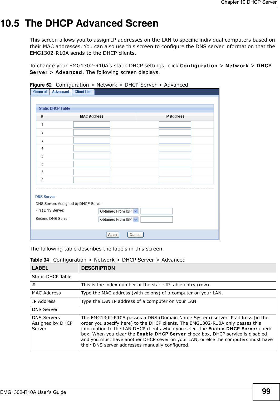
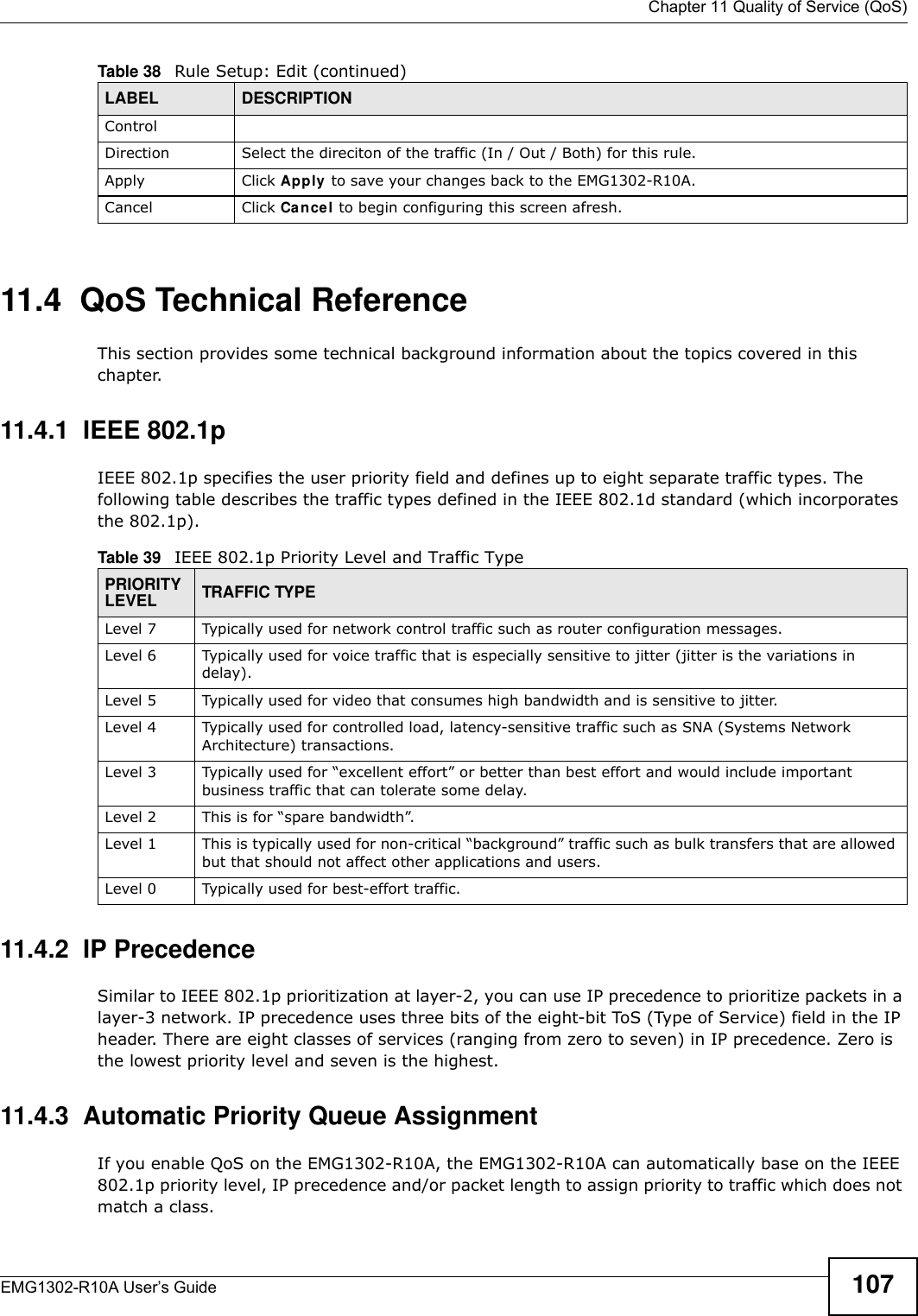
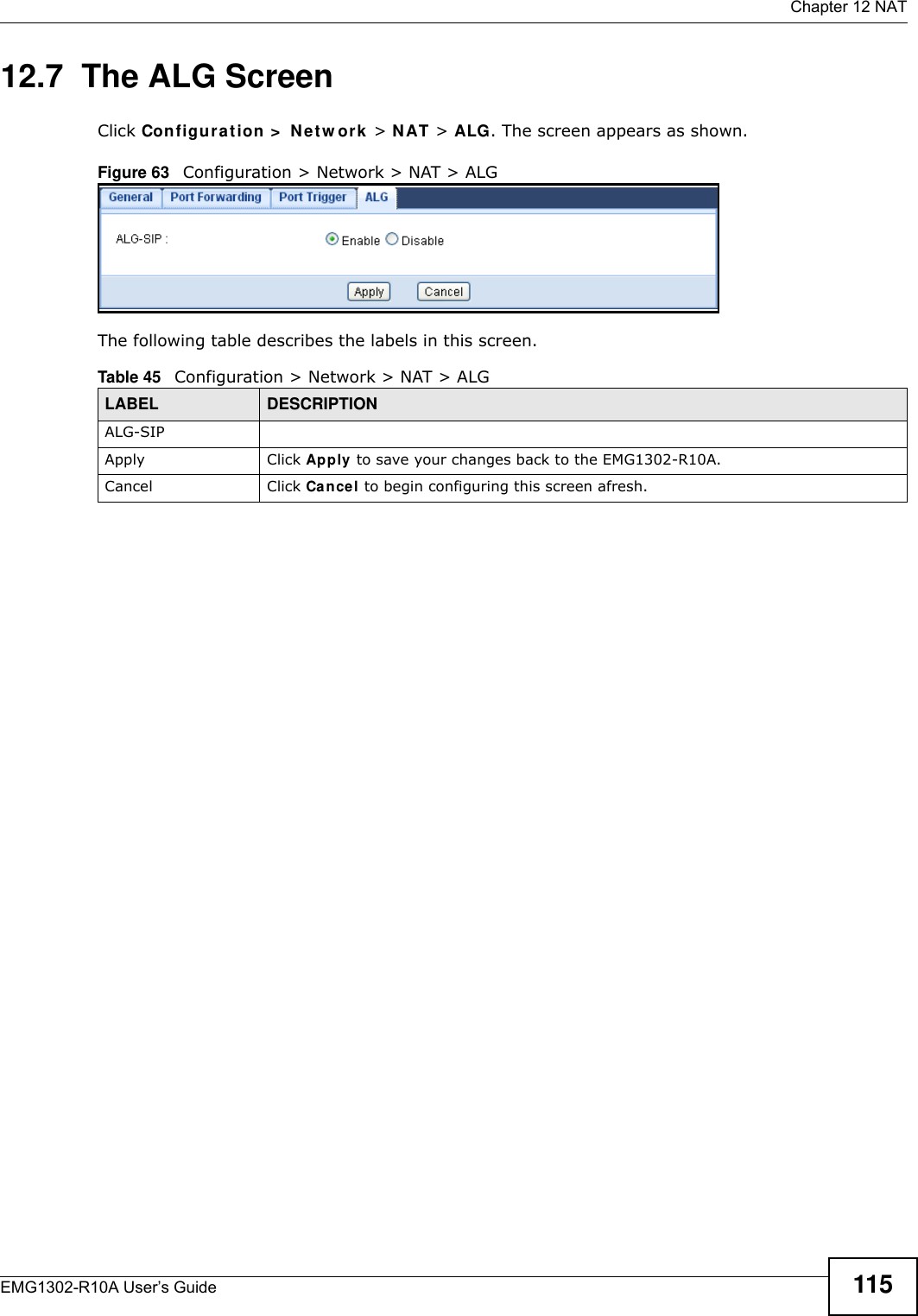
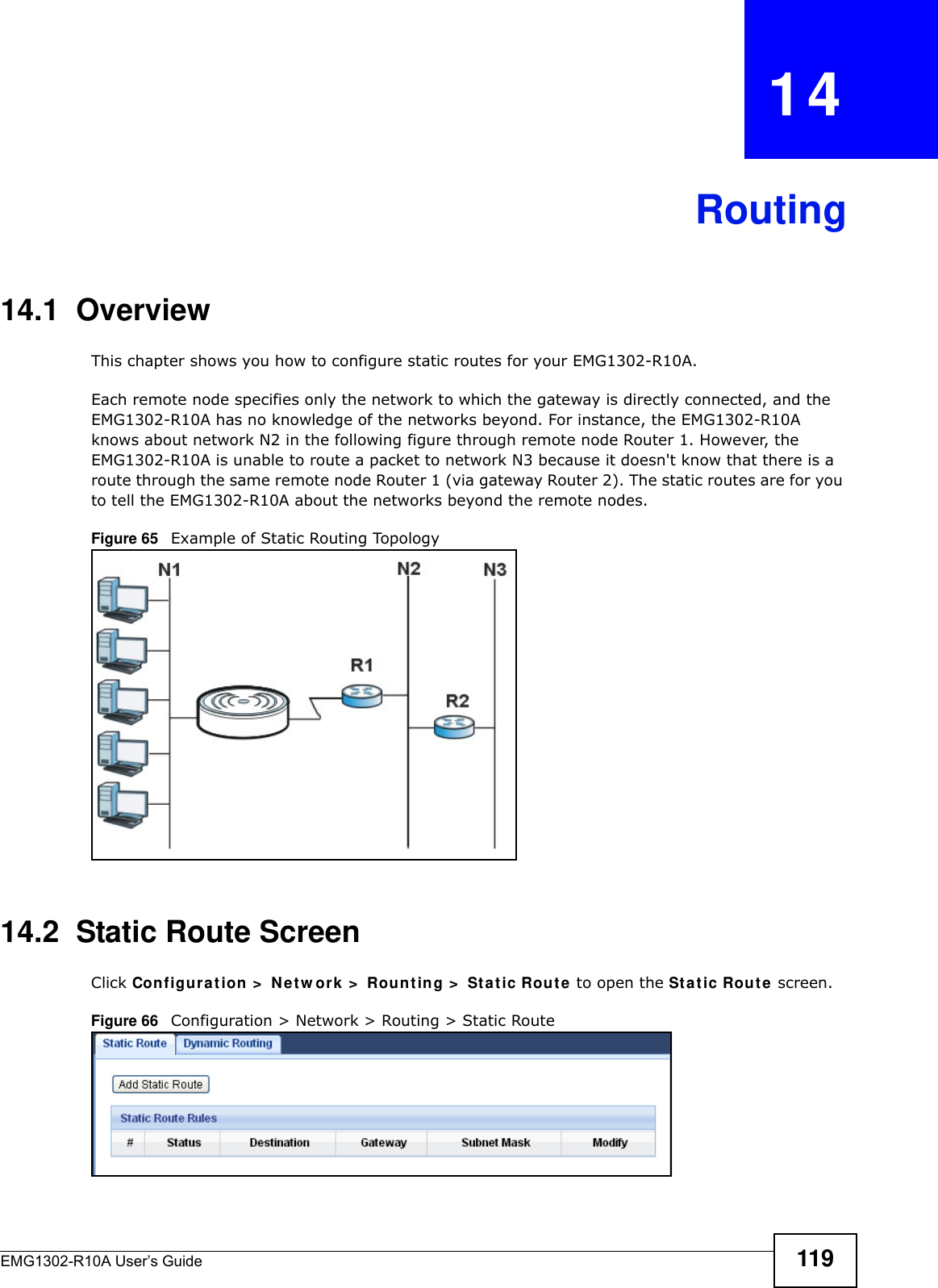

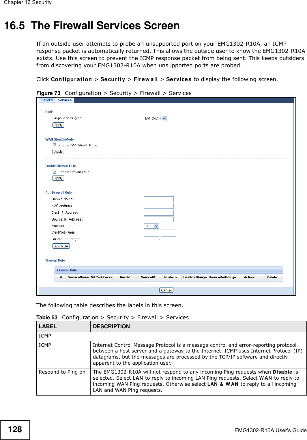


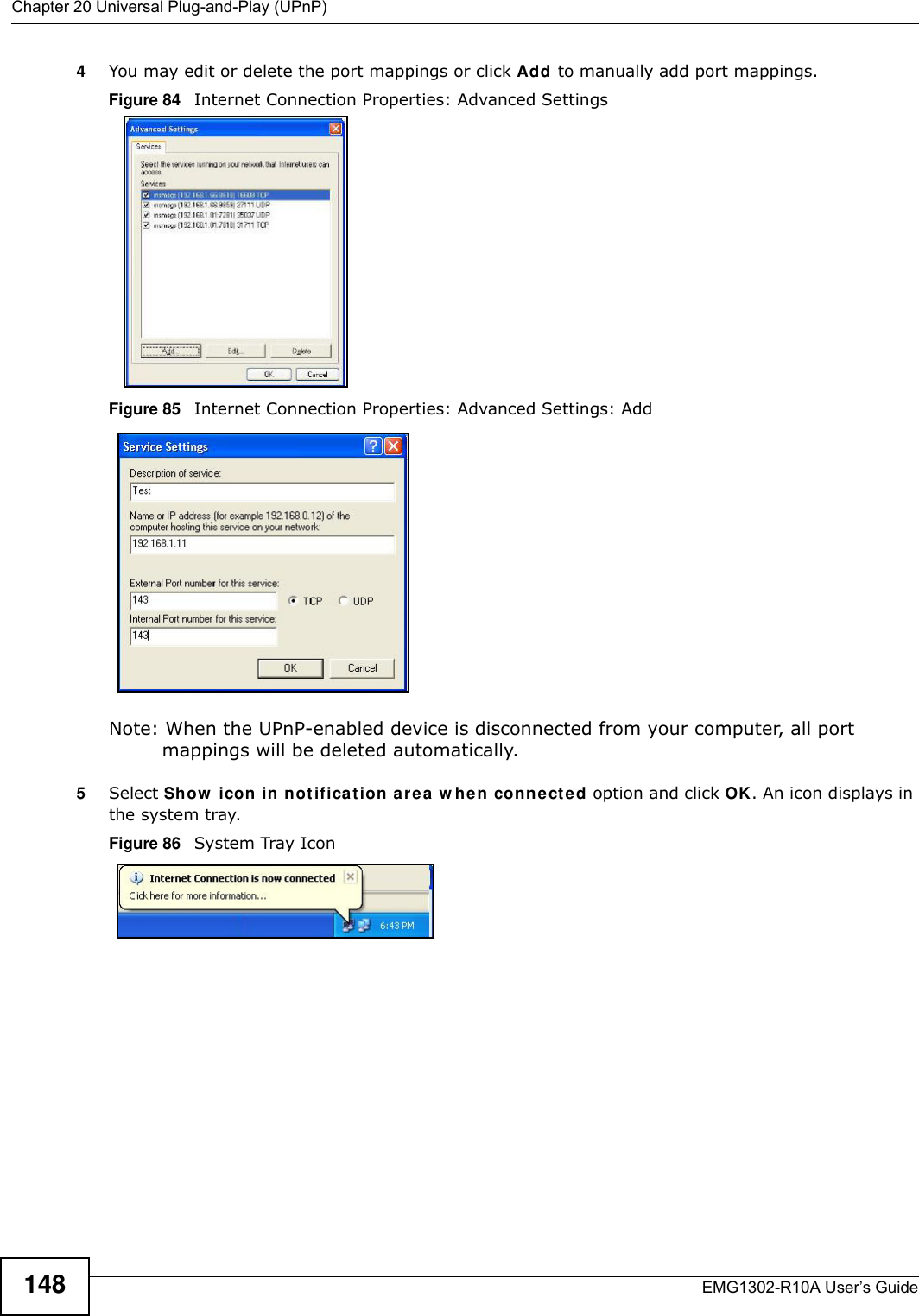

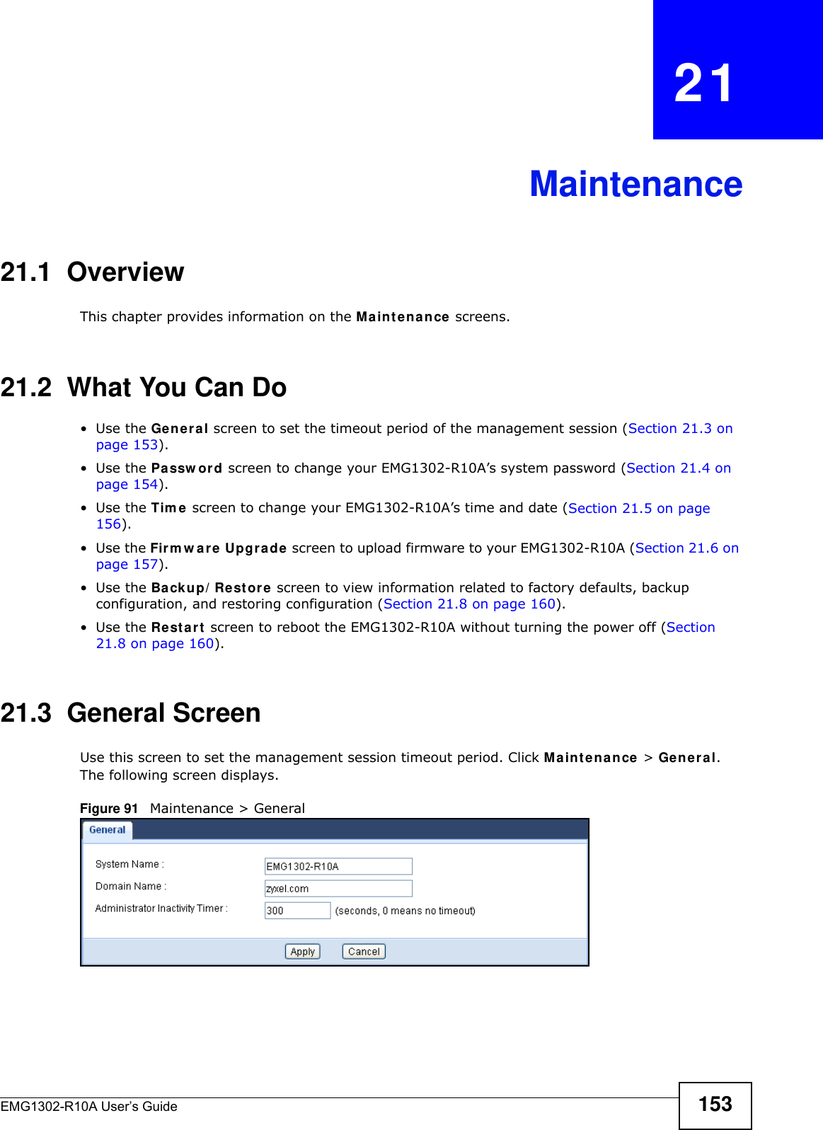
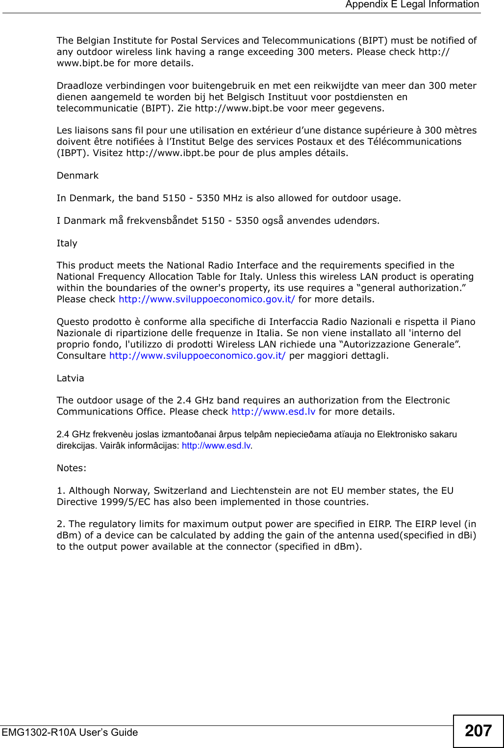
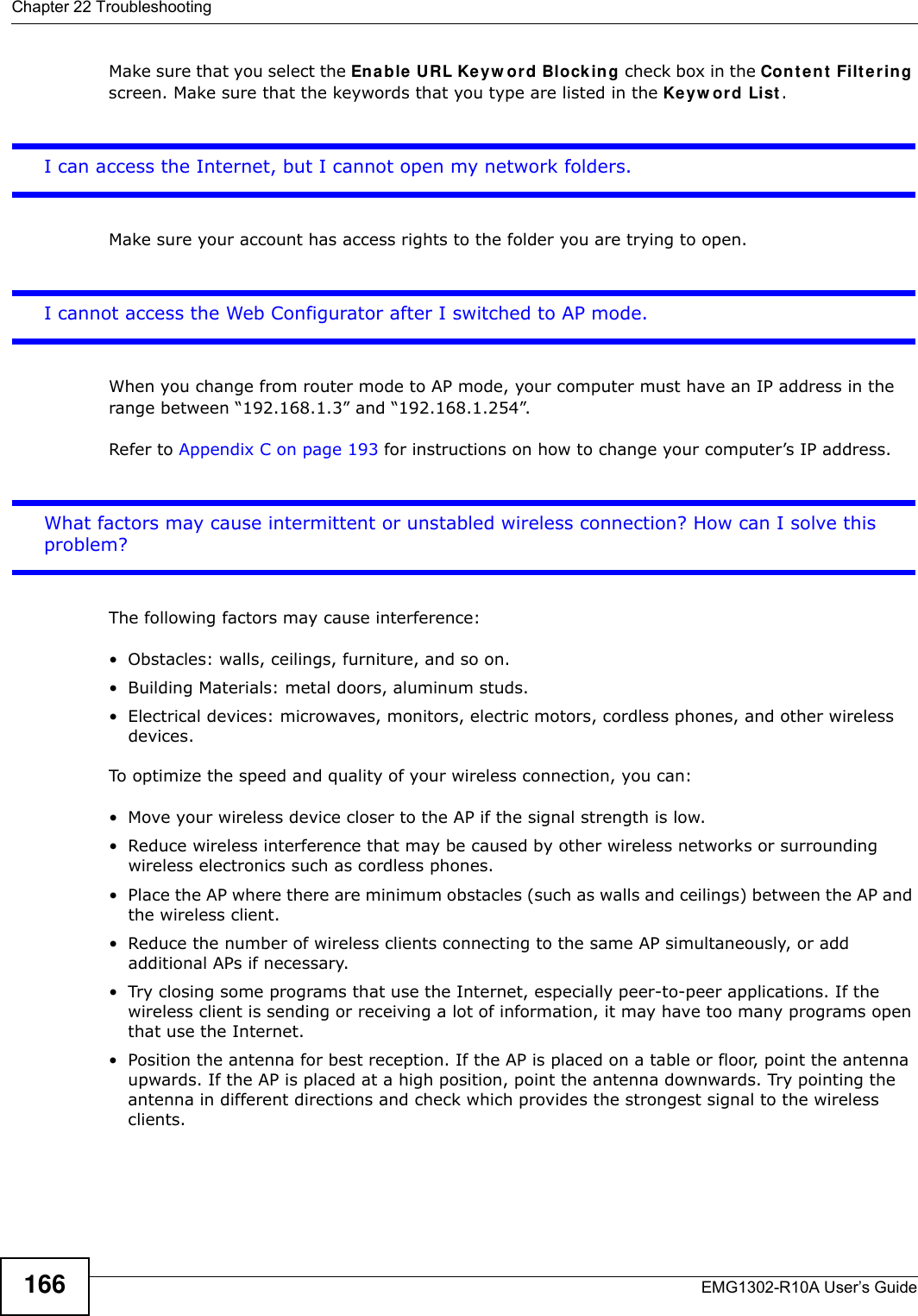
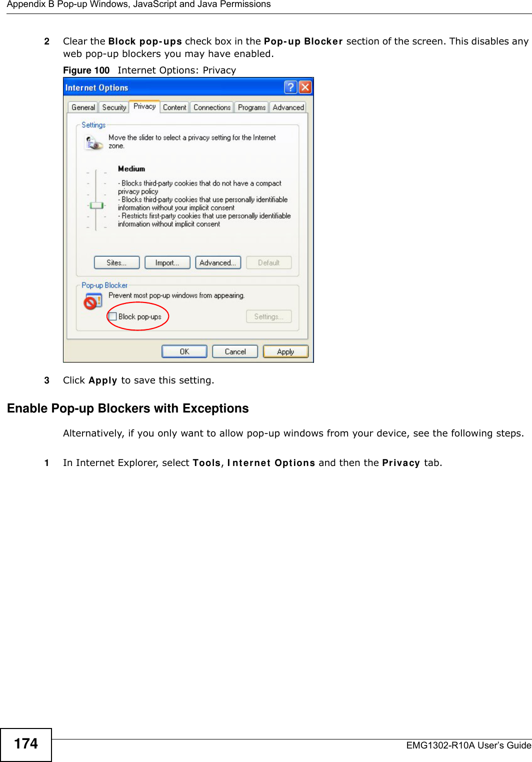
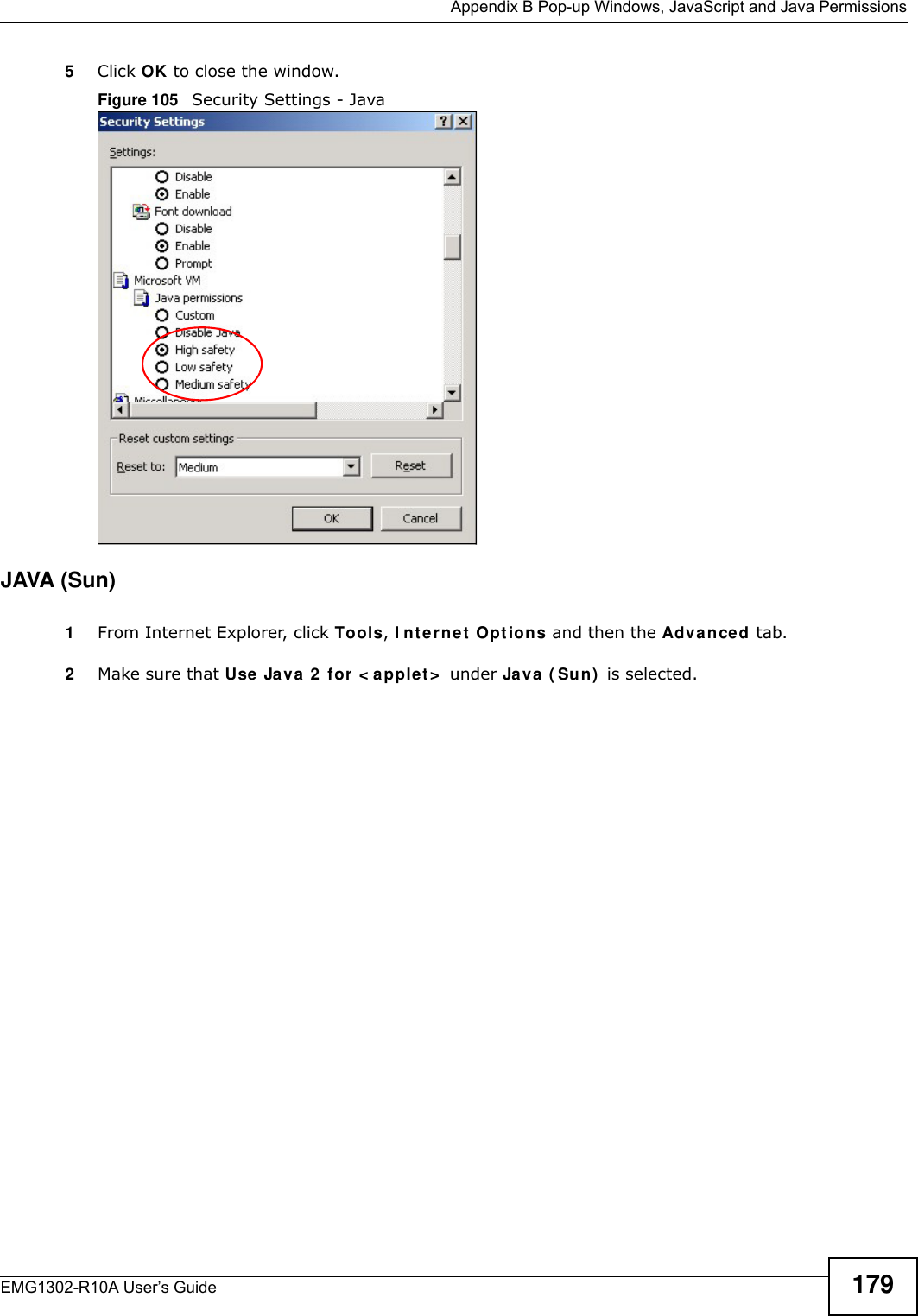
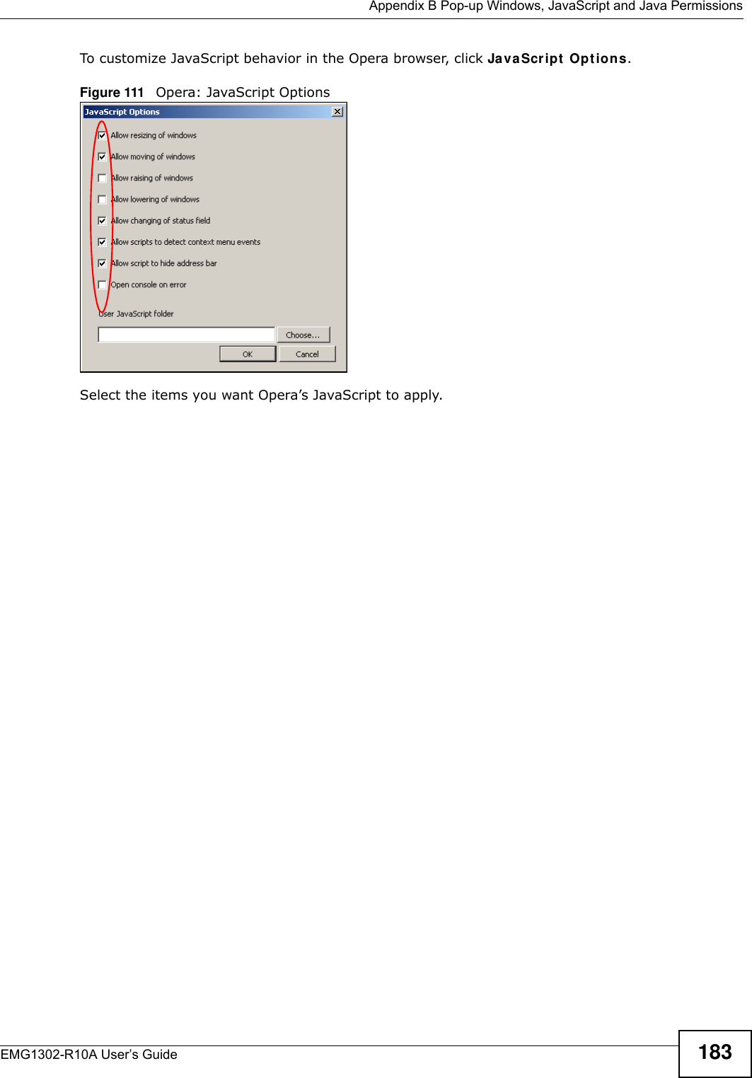
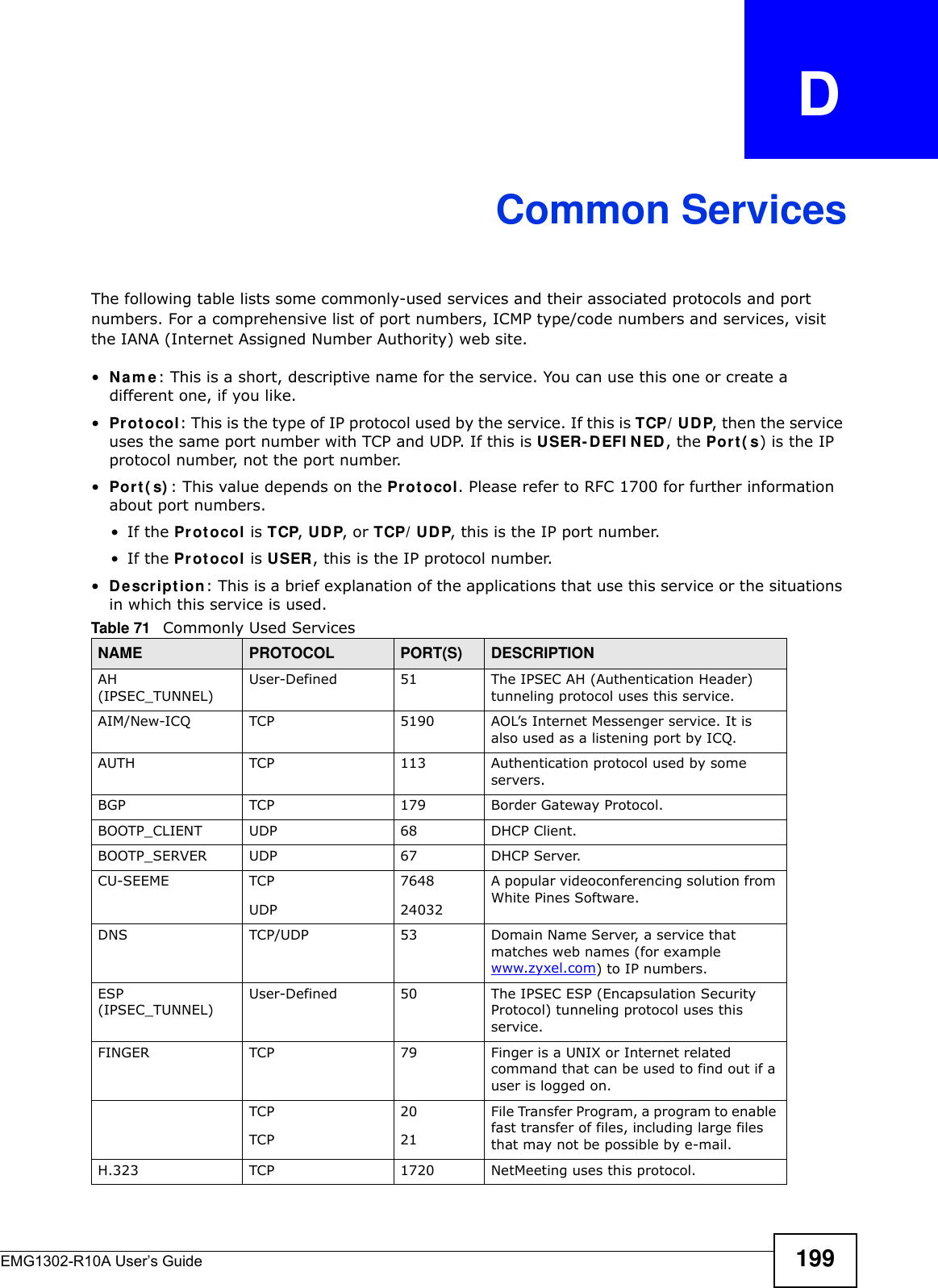
![Chapter 22 TroubleshootingEMG1302-R10A User’s Guide 1633Make sure your Internet browser does not block pop-up windows and has JavaScript and Java enabled. See Appendix B on page 173.4Make sure your computer is in the same subnet as the EMG1302-R10A. (If you know that there are routers between your computer and the EMG1302-R10A, skip this step.)• If there is a DHCP server on your network, make sure your computer is using a dynamic IP address. See Section 9.4 on page 95. • If there is no DHCP server on your network, make sure your computer’s IP address is in the same subnet as the EMG1302-R10A. See Section 9.4 on page 95.5Reset the device to its factory defaults, and try to access the EMG1302-R10A with the default IP address. See Section 2.4 on page 21.6If the problem continues, contact the network administrator or vendor, or try one of the advanced suggestions.Advance d Suggest ions• Try to access the EMG1302-R10A using another service, such as Telnet. If you can access the EMG1302-R10A, check the remote management settings and firewall rules to find out why the EMG1302-R10A does not respond to HTTP.• If your computer is connected to the W AN port or is connected wirelessly, use a computer that is connected to a LAN /ETH ERN ET port.I can see the Login screen, but I cannot log in to the EMG1302-R10A.1Make sure you have entered the password correctly. The default password is 1 2 3 4 . This field is case-sensitive, so make sure [Caps Lock] is not on. 2You cannot log in to the Web Configurator while someone is using Telnet to access the EMG1302-R10A. Log out of the EMG1302-R10A in the other session, or ask the person who is logged in to log out. 3This can happen when you fail to log out properly from your last session. Try logging in again after 5 minutes.4Disconnect and re-connect the power adaptor or cord to the EMG1302-R10A. 5If this does not work, you have to reset the device to its factory defaults. See Section 22.5 on page 164.22.4 Internet AccessI cannot access the Internet.](https://usermanual.wiki/ZyXEL-Communications/EMG1302R10A/User-Guide-2198186-Page-163.png)
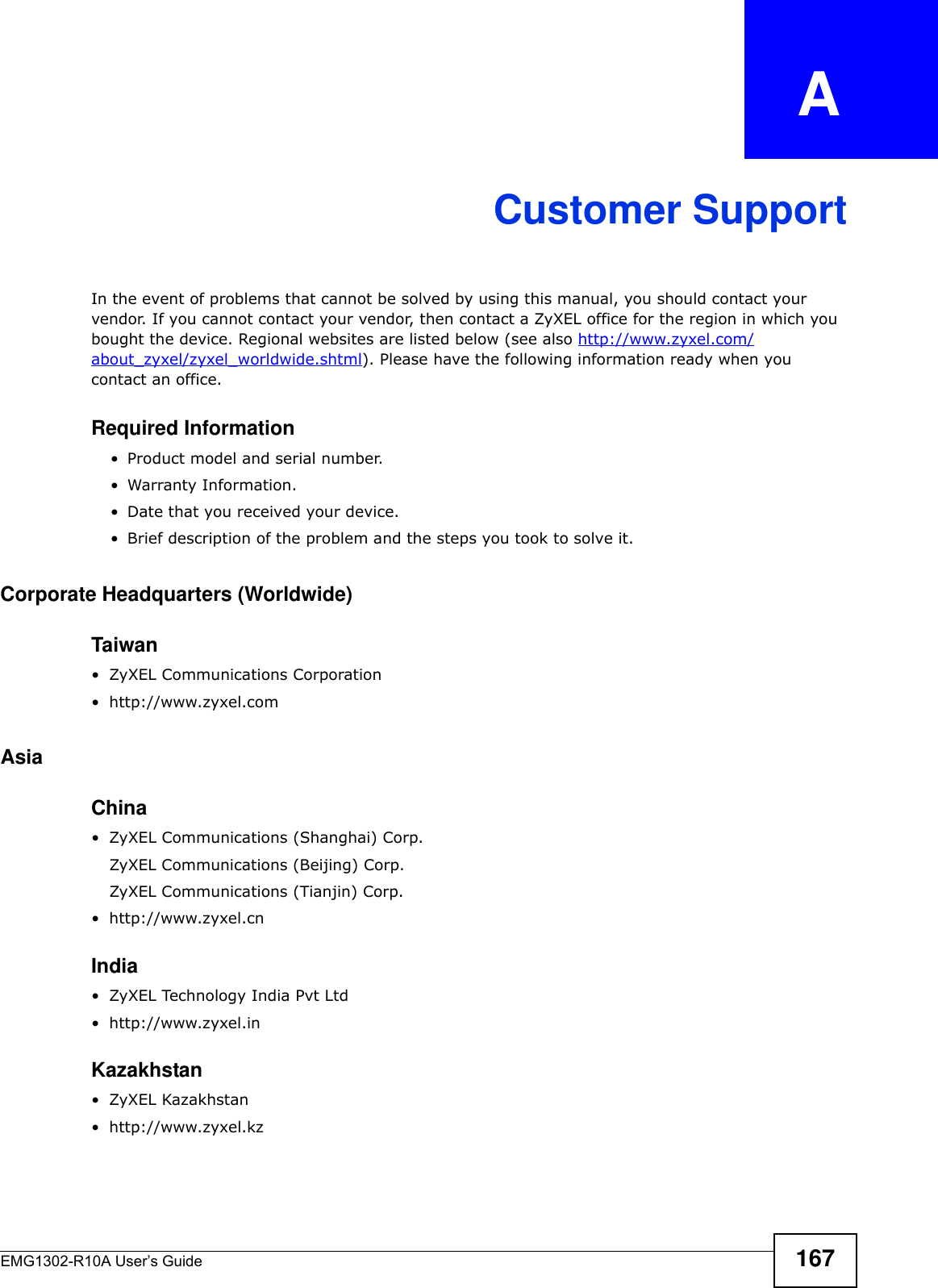
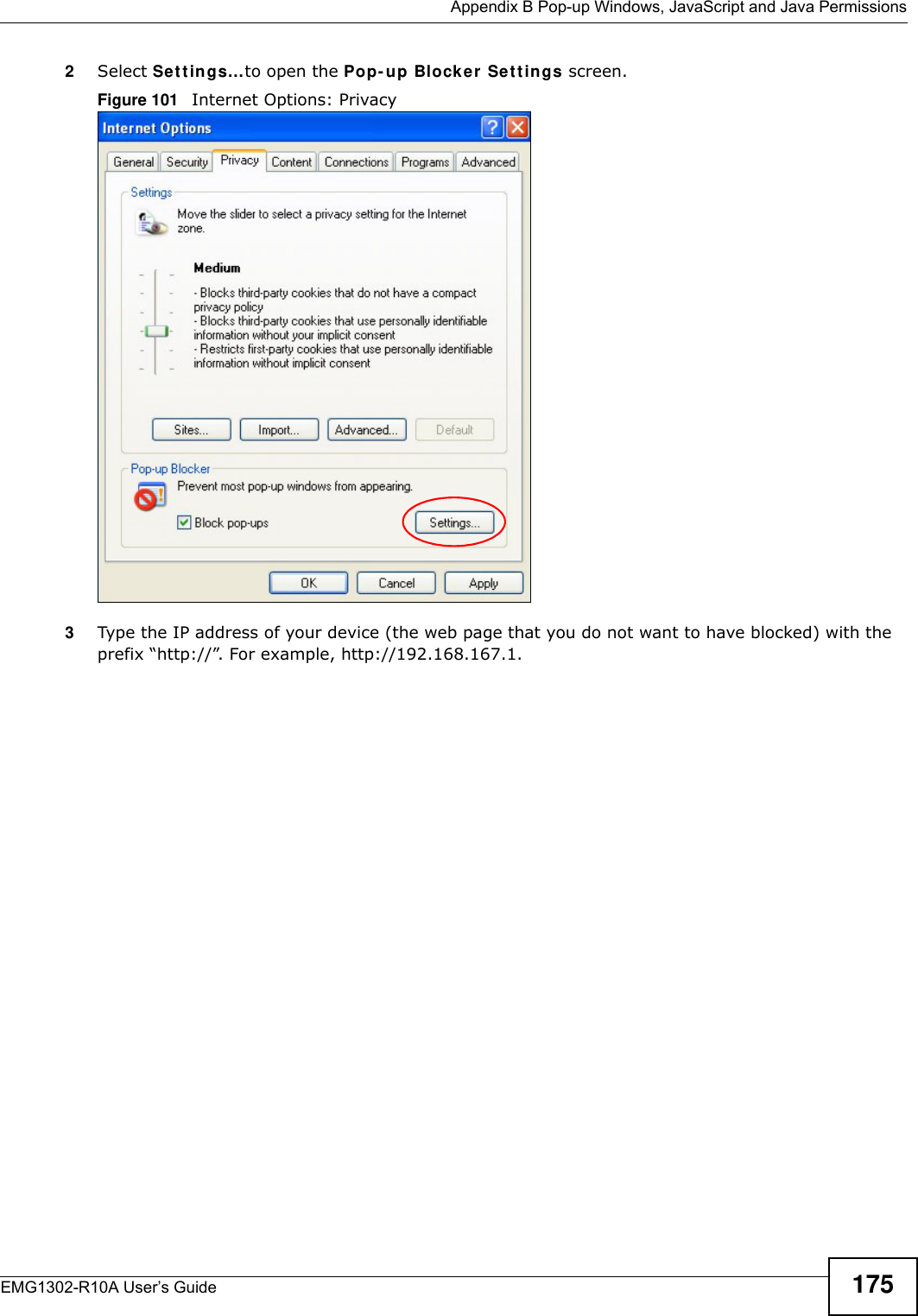

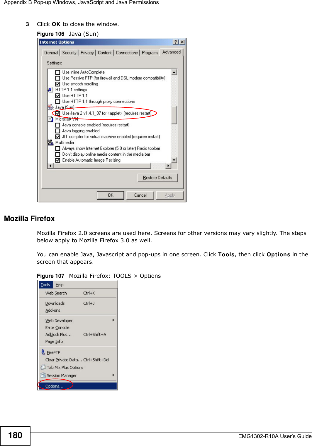
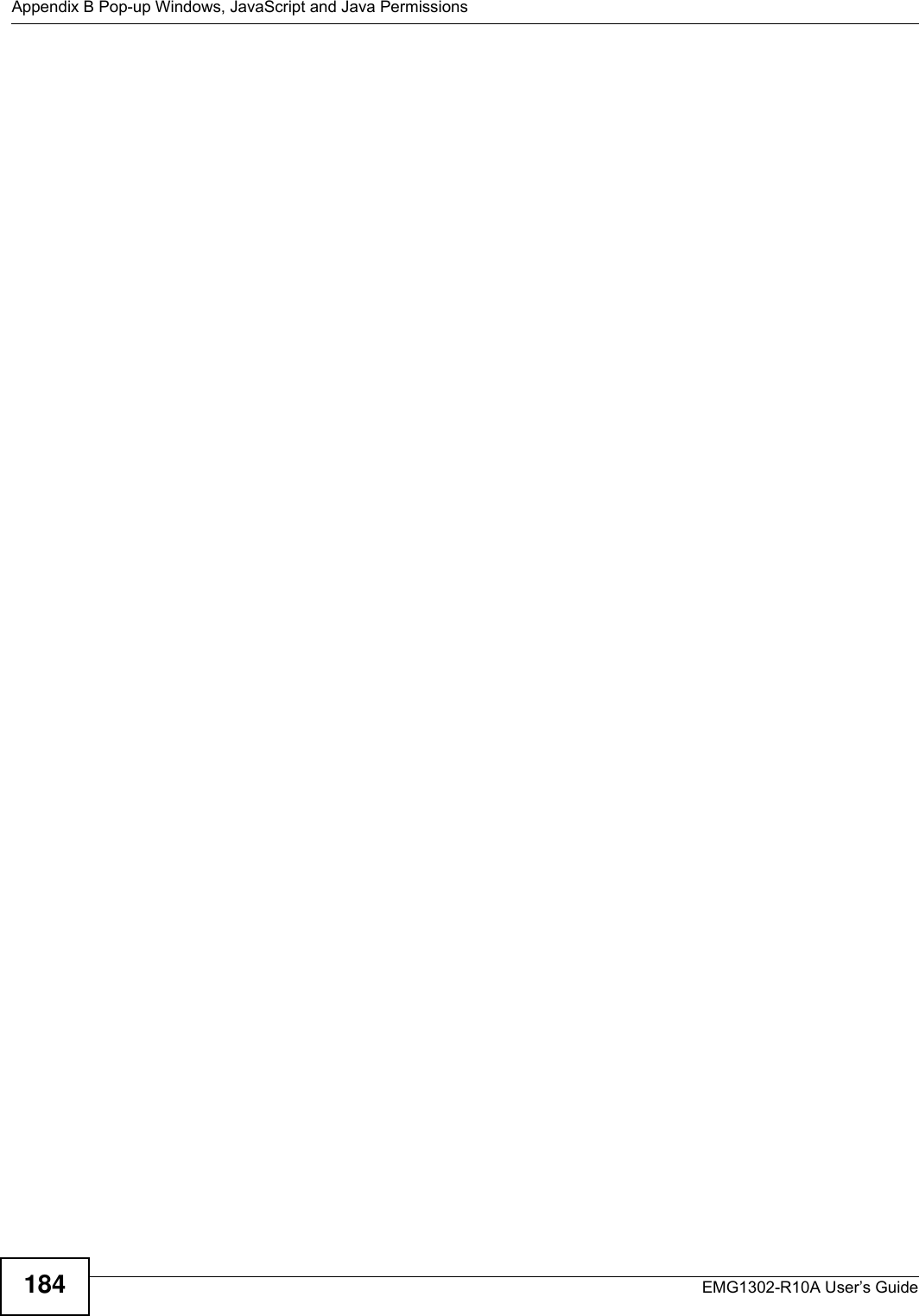
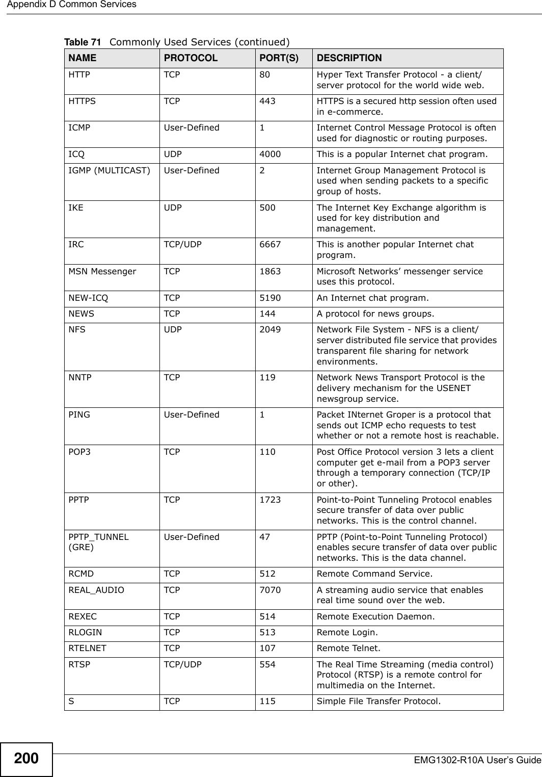

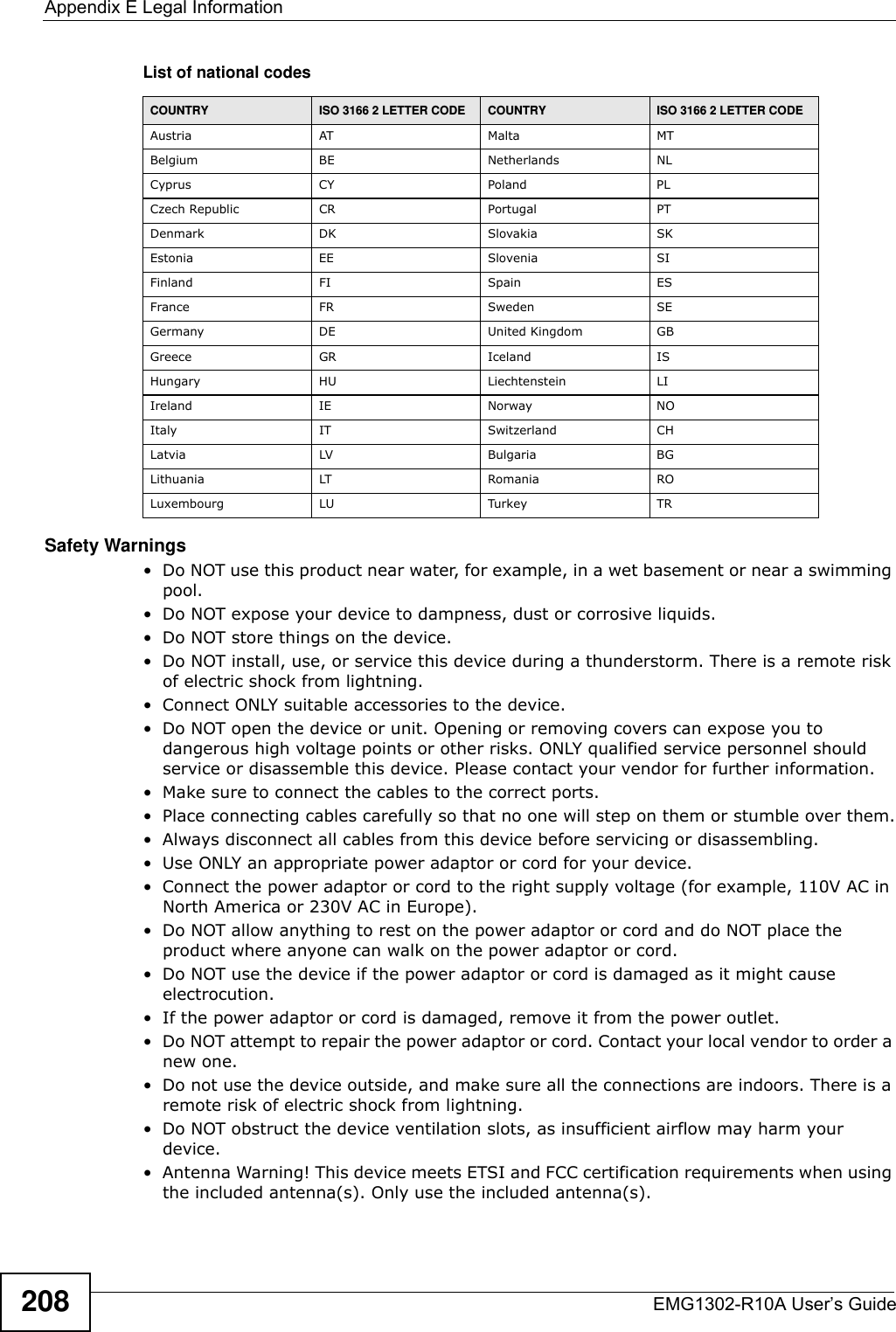
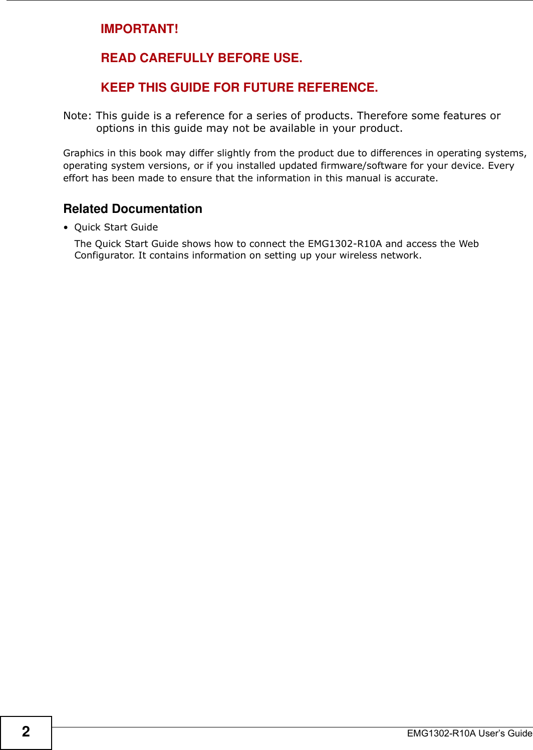
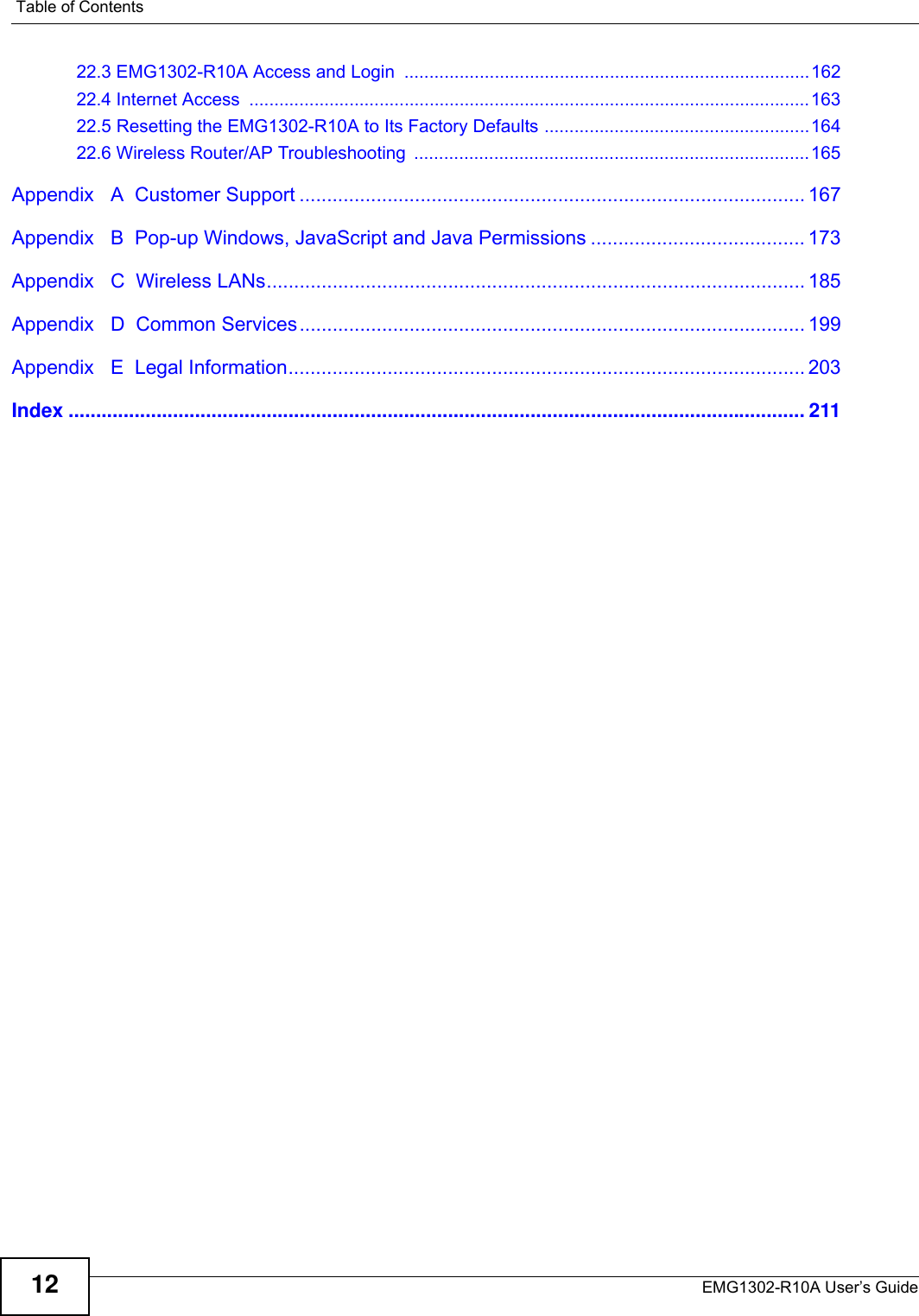
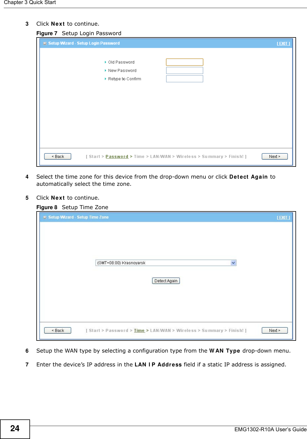
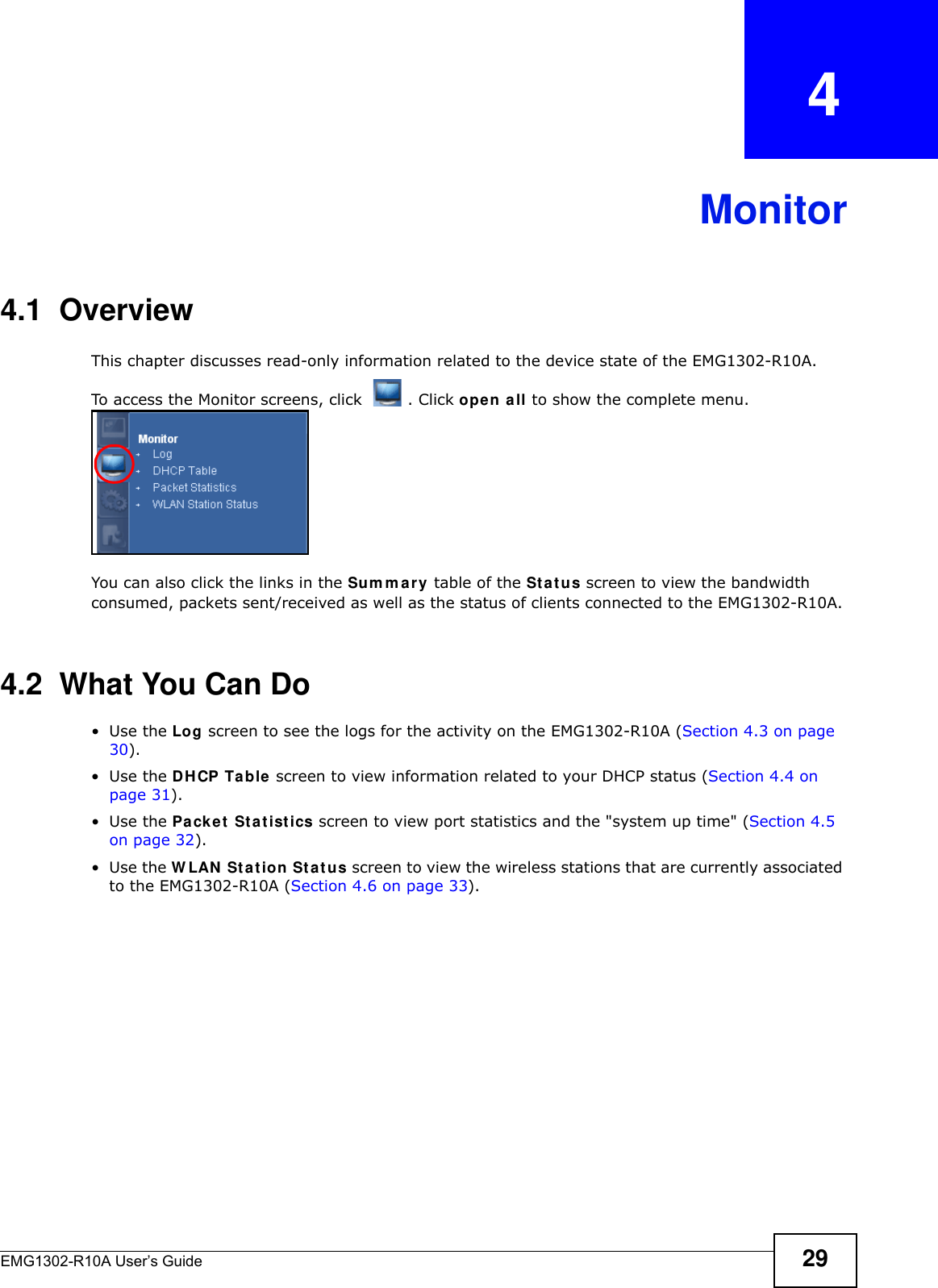
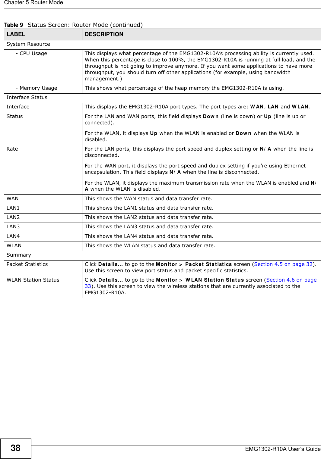
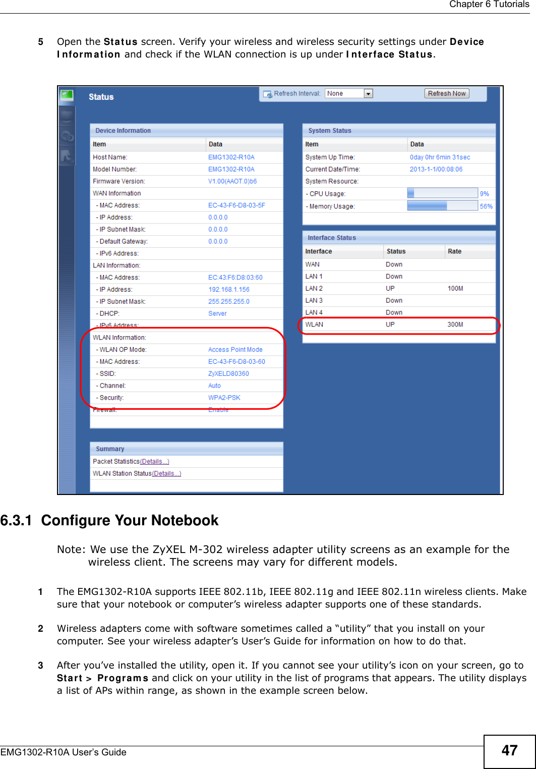
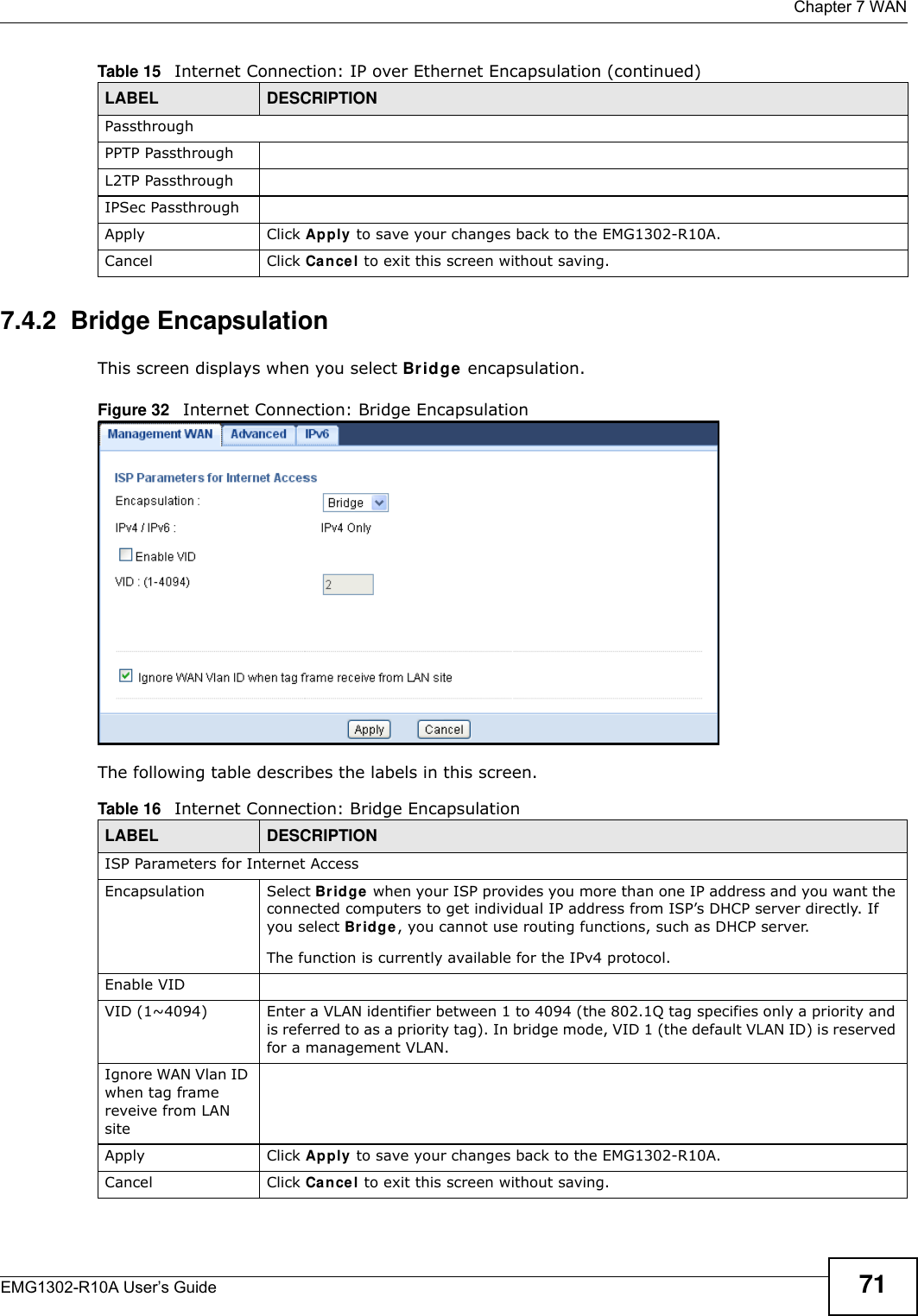
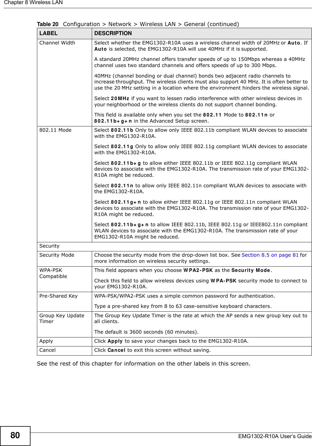
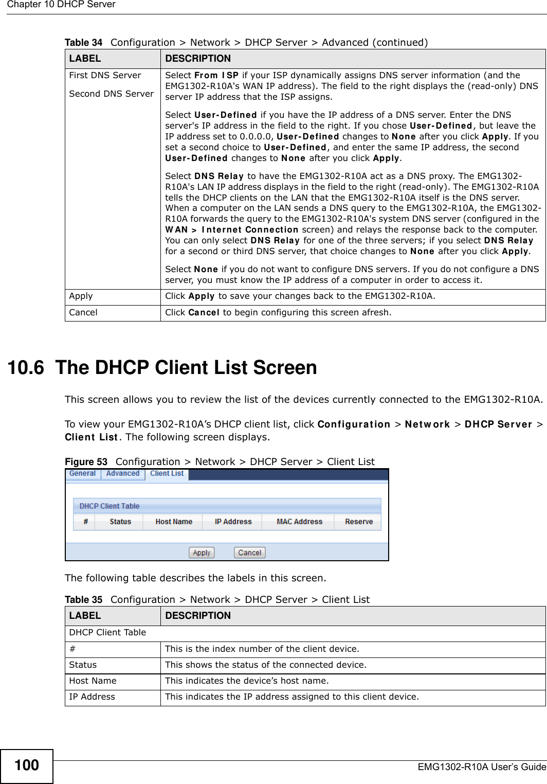
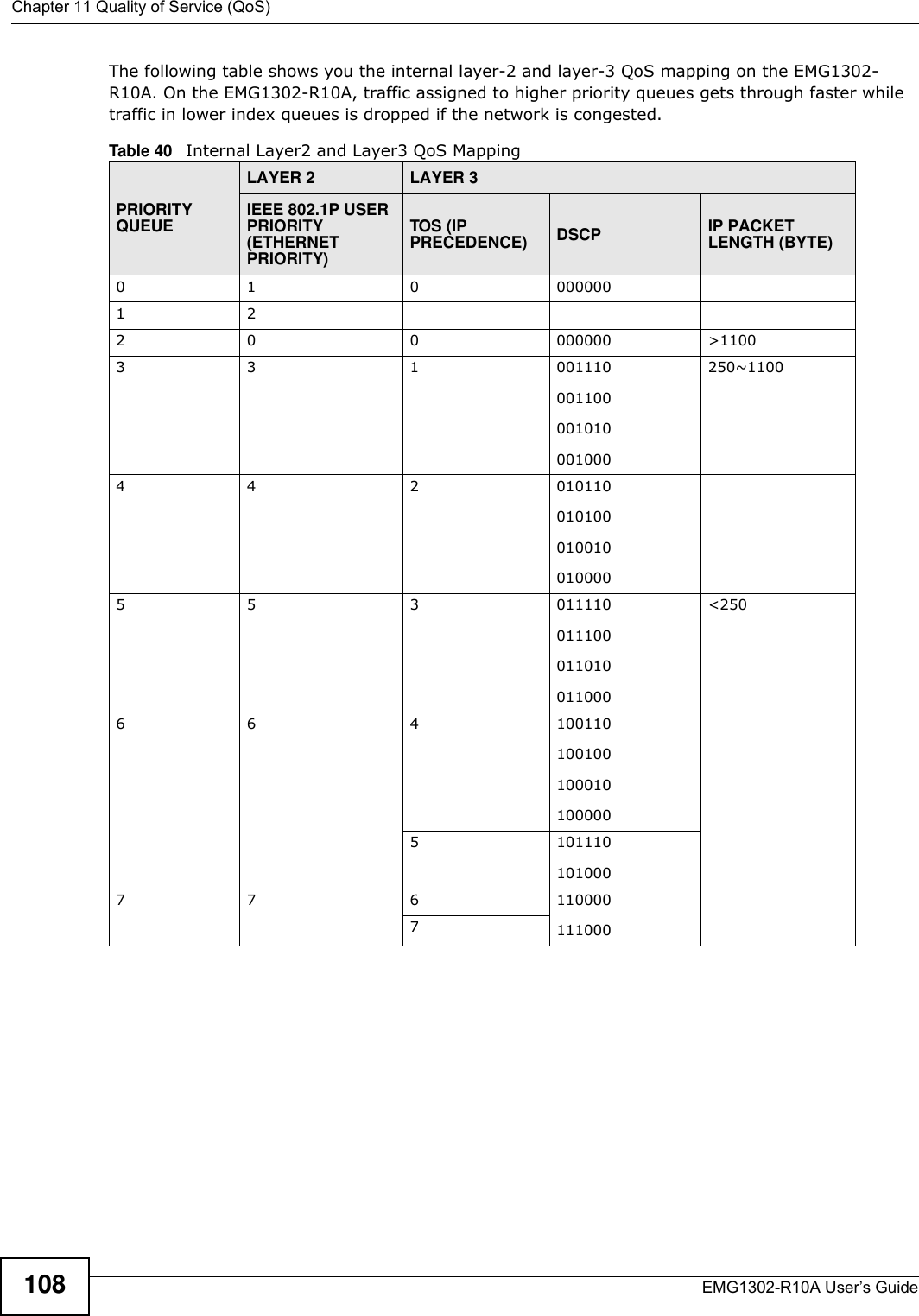
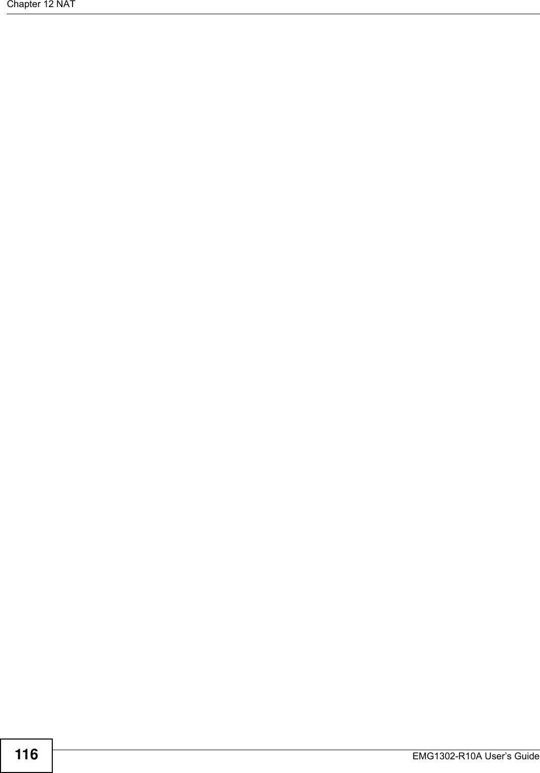
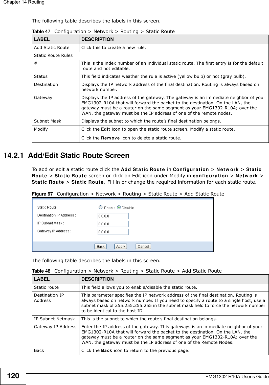
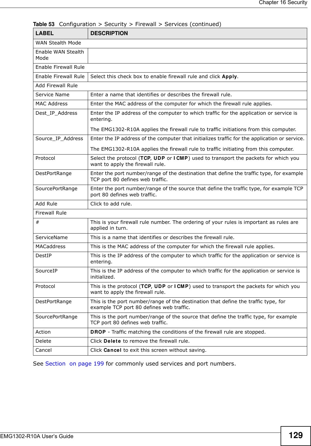
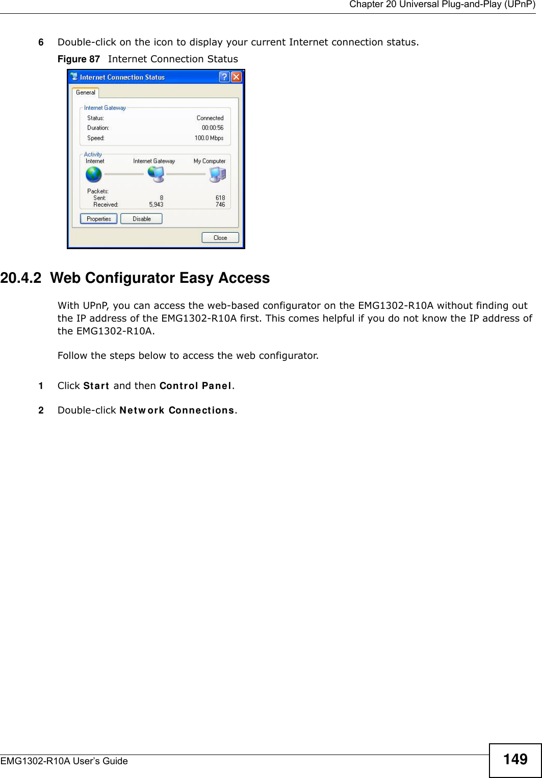
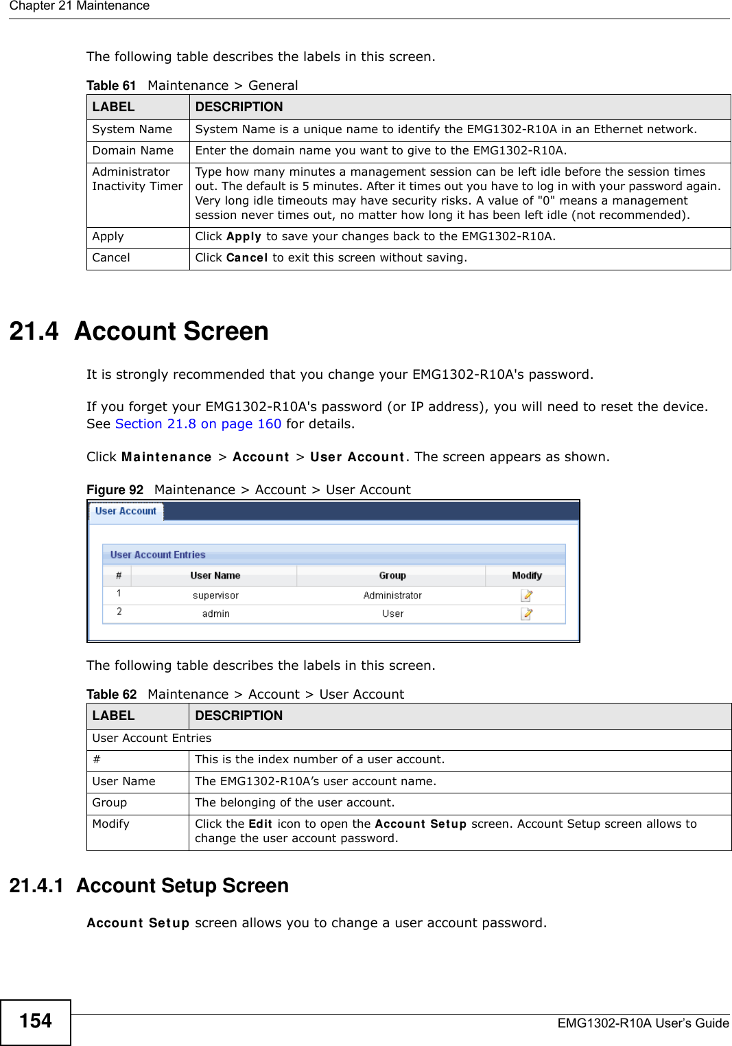
![Appendix E Legal InformationEMG1302-R10A User’s Guide 205RegistrationRegister your product online to receive e-mail notices of firmware upgrades and information at www.zyxel.com for global products, or at www.us.zyxel.com for North American products.Open Source LicensesThis product contains in part some free software distributed under GPL license terms and/or GPL like licenses. Open source licenses are provided with the firmware package. You can download the latest firmware at www.zyxel.com. If you cannot find it there, contact your vendor or ZyXEL Technical Support at support@zyxel.com.tw To obtain the source code covered under those Licenses, please contact your vendor or ZyXEL Technical Support at support@zyxel.com.twRegulatory Information European UnionThe following information applies if you use the product within the European Union. Declaration of Conformity with Regard to EU Directive 1999/5/EC (R&TTE Directive)Compliance Information for 2.4GHz and 5GHz Wireless Products Relevant to the EU and Other Countries Following the EU Directive 1999/5/EC (R&TTE Directive) [Czech] ZyXEL tímto prohlašuje, že tento zařízení je ve shodě se základními požadavky a dalšími příslušnými ustanoveními směrnice 1999/5/EC.[Danish] Undertegnede ZyXEL erklærer herved, at følgende udstyr udstyr overholder de væsentlige krav og øvrige relevante krav i direktiv 1999/5/EF.[German] Hiermit erklärt ZyXEL, dass sich das Gerät Ausstattung in Übereinstimmung mit den grundlegenden Anforderungen und den übrigen einschlägigen Bestimmungen der Richtlinie 1999/5/EU befindet.[Estonian] Käesolevaga kinnitab ZyXEL seadme seadmed vastavust direktiivi 1999/5/EÜ põhinõuetele ja nimetatud direktiivist tulenevatele teistele asjakohastele sätetele.English Hereby, ZyXEL declares that this equipment is in compliance with the essential requirements and other relevant provisions of Directive 1999/5/EC.[Spanish] Por medio de la presente ZyXEL declara que el equipo cumple con los requisitos esenciales y cualesquiera otras disposiciones aplicables o exigibles de la Directiva 1999/5/CE.[Greek] Ε Η ΑΑ ZyXEL ∆ΗΩΕ επισός ΦΩΕΑ Ω∆Ε ΑΑΗΕ Α Ε ΧΕΕ ∆ΑΑΕ Η ∆ΗΓΑ 1999/5/ΕC.[French] Par la présente ZyXEL déclare que l'appareil équipements est conforme aux exigences essentielles et aux autres dispositions pertinentes de la directive 1999/5/EC.[Italian] Con la presente ZyXEL dichiara che questo attrezzatura è conforme ai requisiti essenziali ed alle altre disposizioni pertinenti stabilite dalla direttiva 1999/5/CE.[Latvian] Ar šo ZyXEL deklarē, ka iekārtas atbilst Direktīvas 1999/5/EK būtiskajām prasībām un citiem ar to saistītajiem noteikumiem.[Lithuanian] Šiuo ZyXEL deklaruoja, kad šis įranga atitinka esminius reikalavimus ir kitas 1999/5/EB Direktyvos nuostatas.[Dutch] Hierbij verklaart ZyXEL dat het toestel uitrusting in overeenstemming is met de essentiële eisen en de andere relevante bepalingen van richtlijn 1999/5/EC.[Maltese] Hawnhekk, ZyXEL, jiddikjara li dan tagħmir jikkonforma mal-ħtiġijiet essenzjali u ma provvedimenti oħrajn relevanti li hemm fid-Dirrettiva 1999/5/EC.[Hungarian] Alulírott, ZyXEL nyilatkozom, hogy a berendezés megfelel a vonatkozó alapvetõ követelményeknek és az 1999/5/EK irányelv egyéb elõírásainak.[Polish] Niniejszym ZyXEL oświadcza, że sprzęt jest zgodny z zasadniczymi wymogami oraz pozostałymi stosownymi postanowieniami Dyrektywy 1999/5/EC.[Portuguese] ZyXEL declara que este equipamento está conforme com os requisitos essenciais e outras disposições da Directiva 1999/5/EC.](https://usermanual.wiki/ZyXEL-Communications/EMG1302R10A/User-Guide-2198186-Page-205.png)
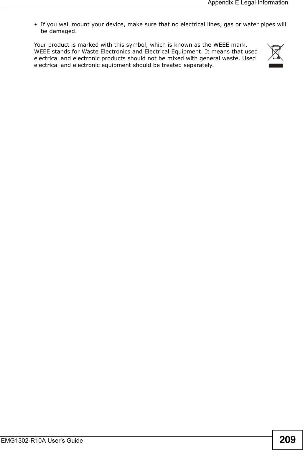
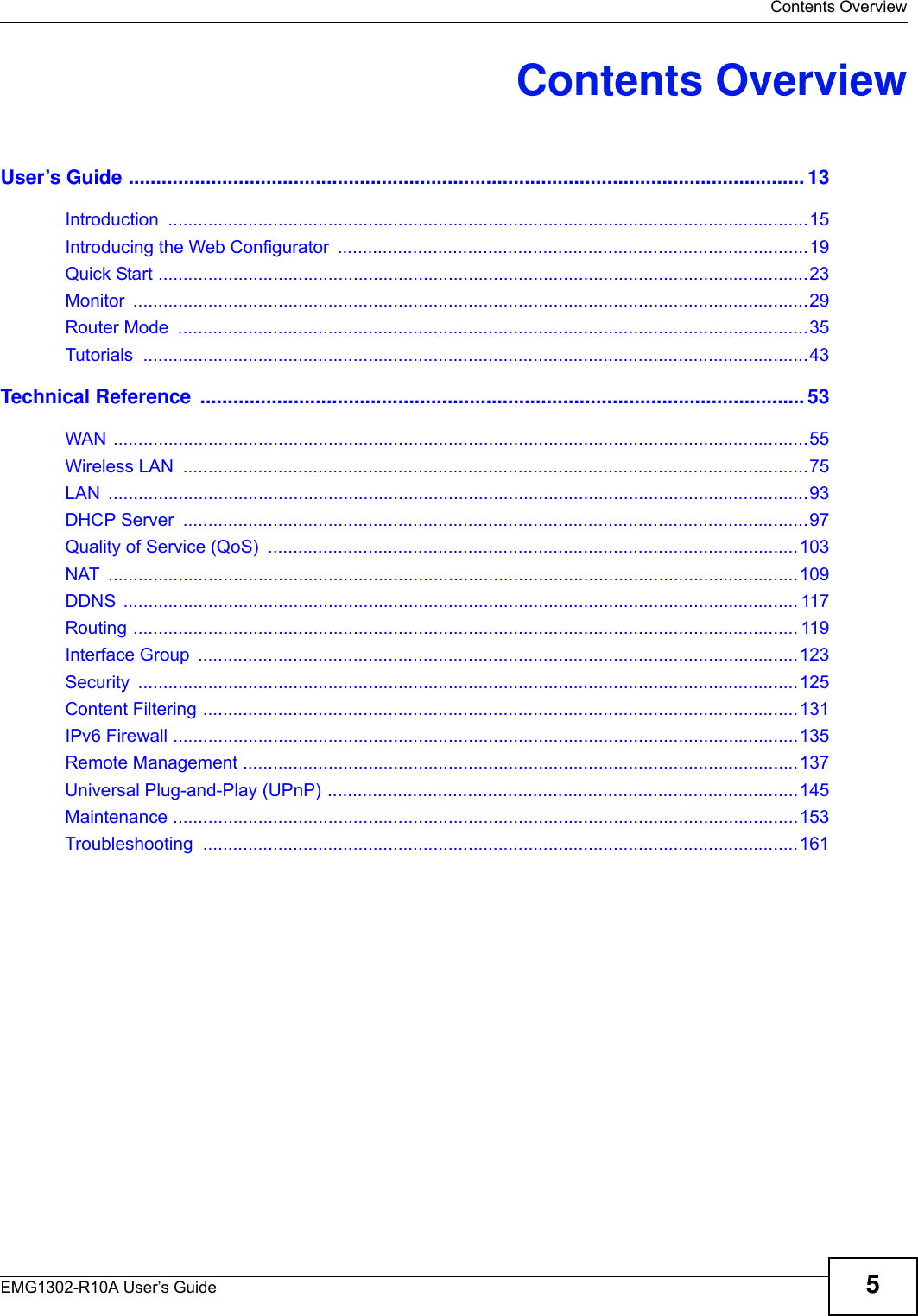
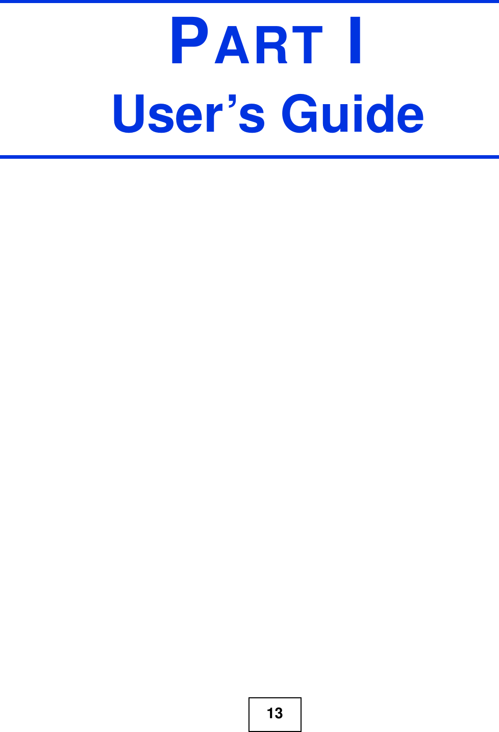
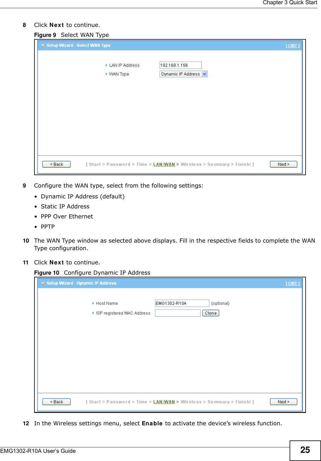
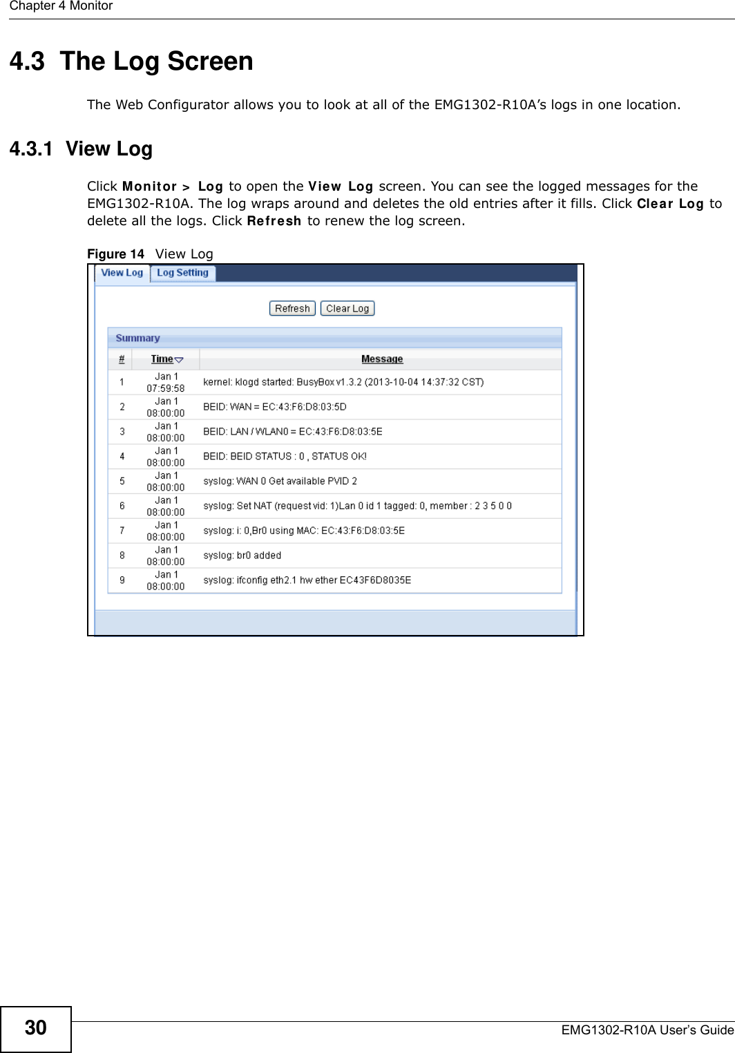
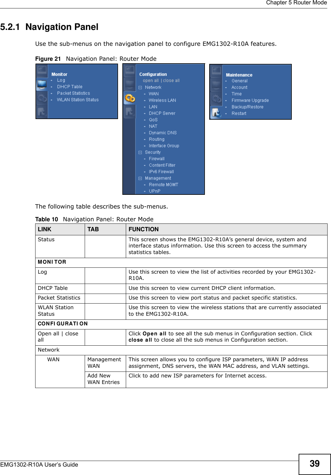
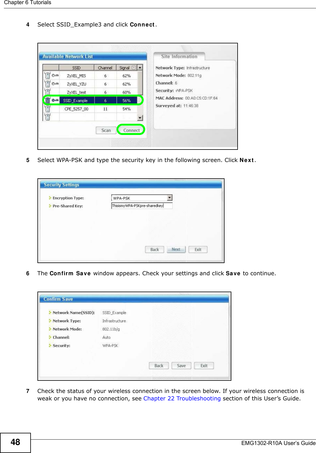
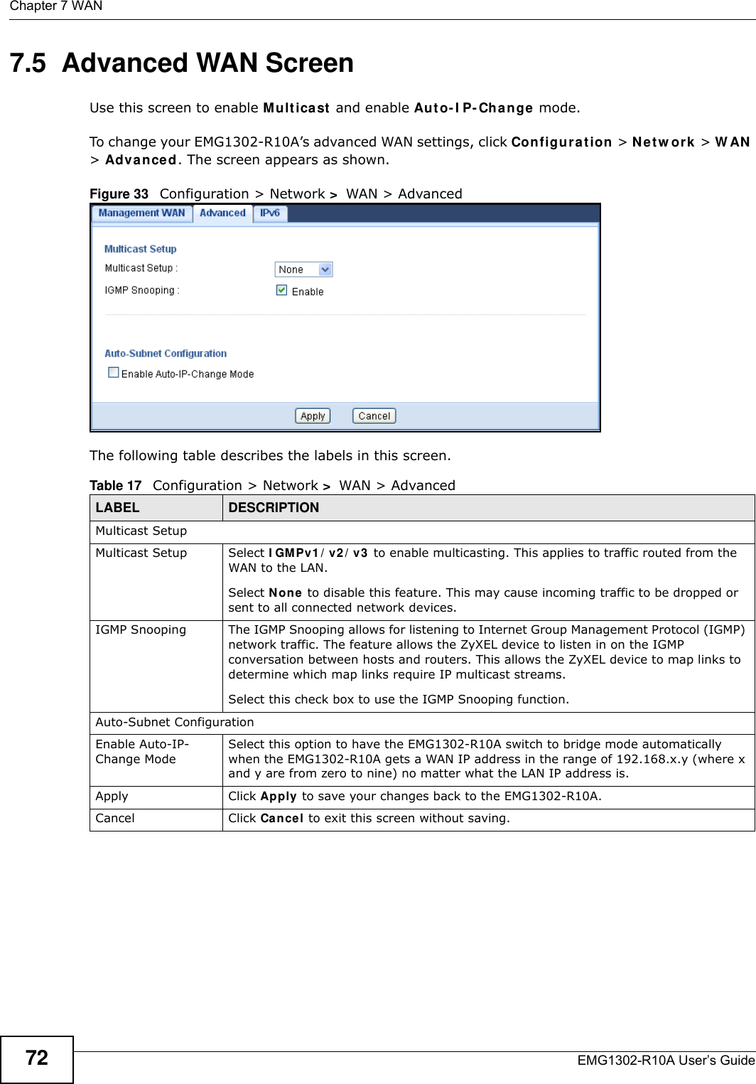
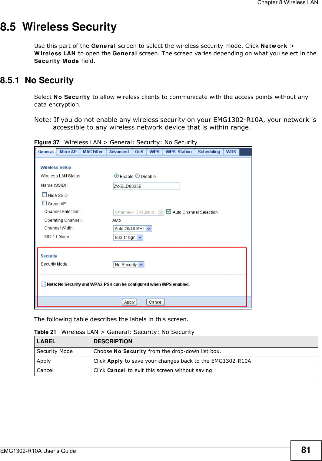
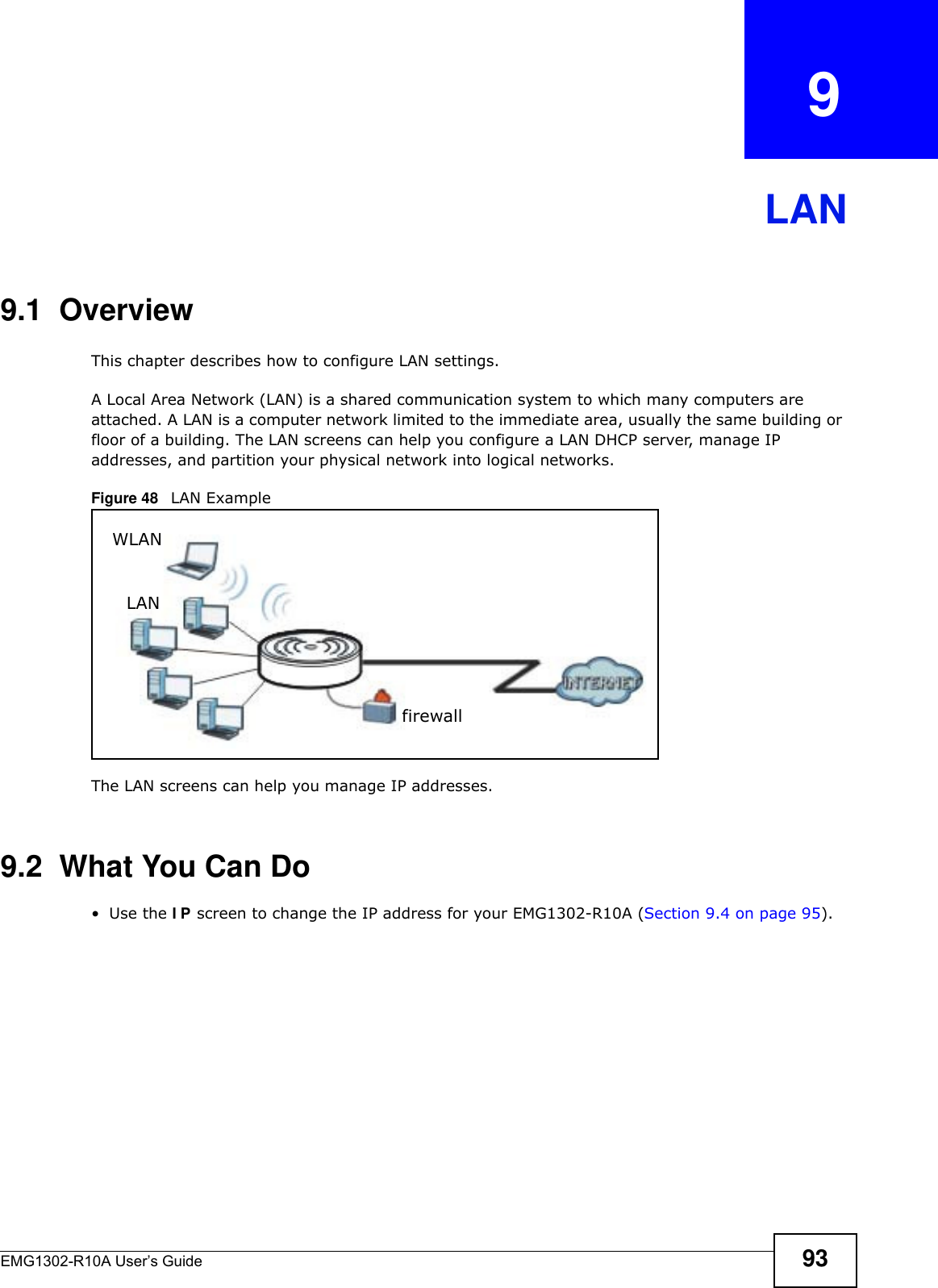
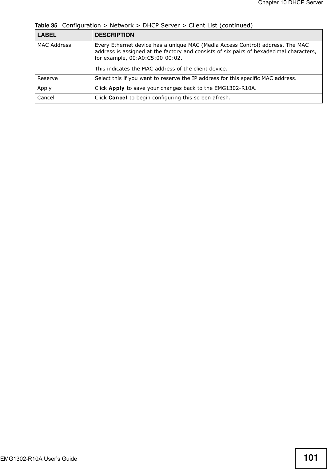
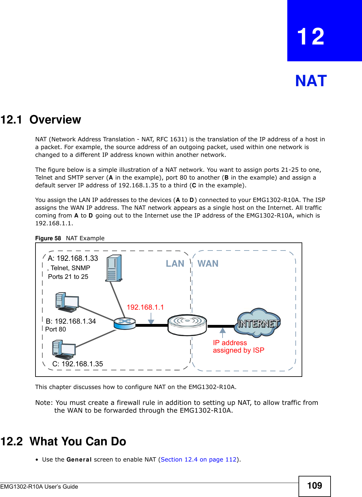
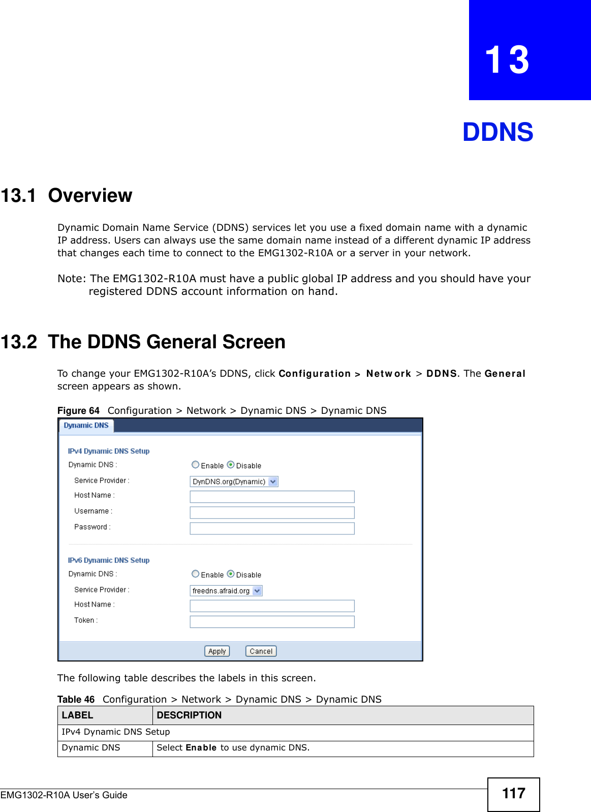
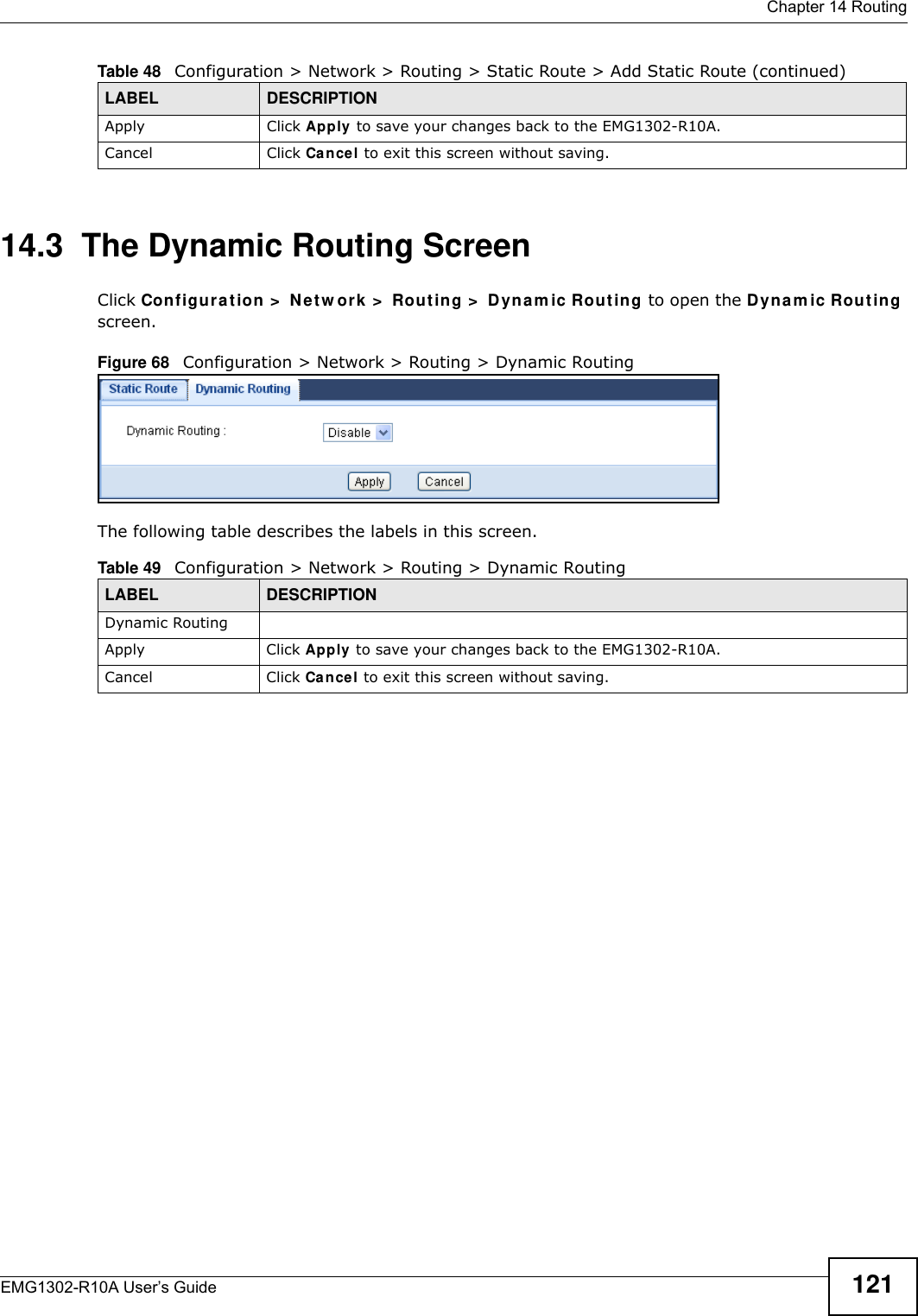
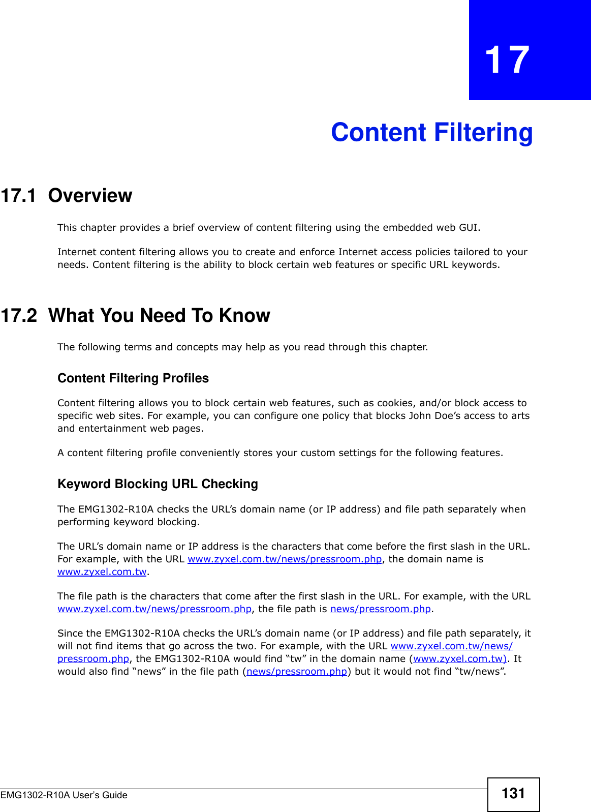
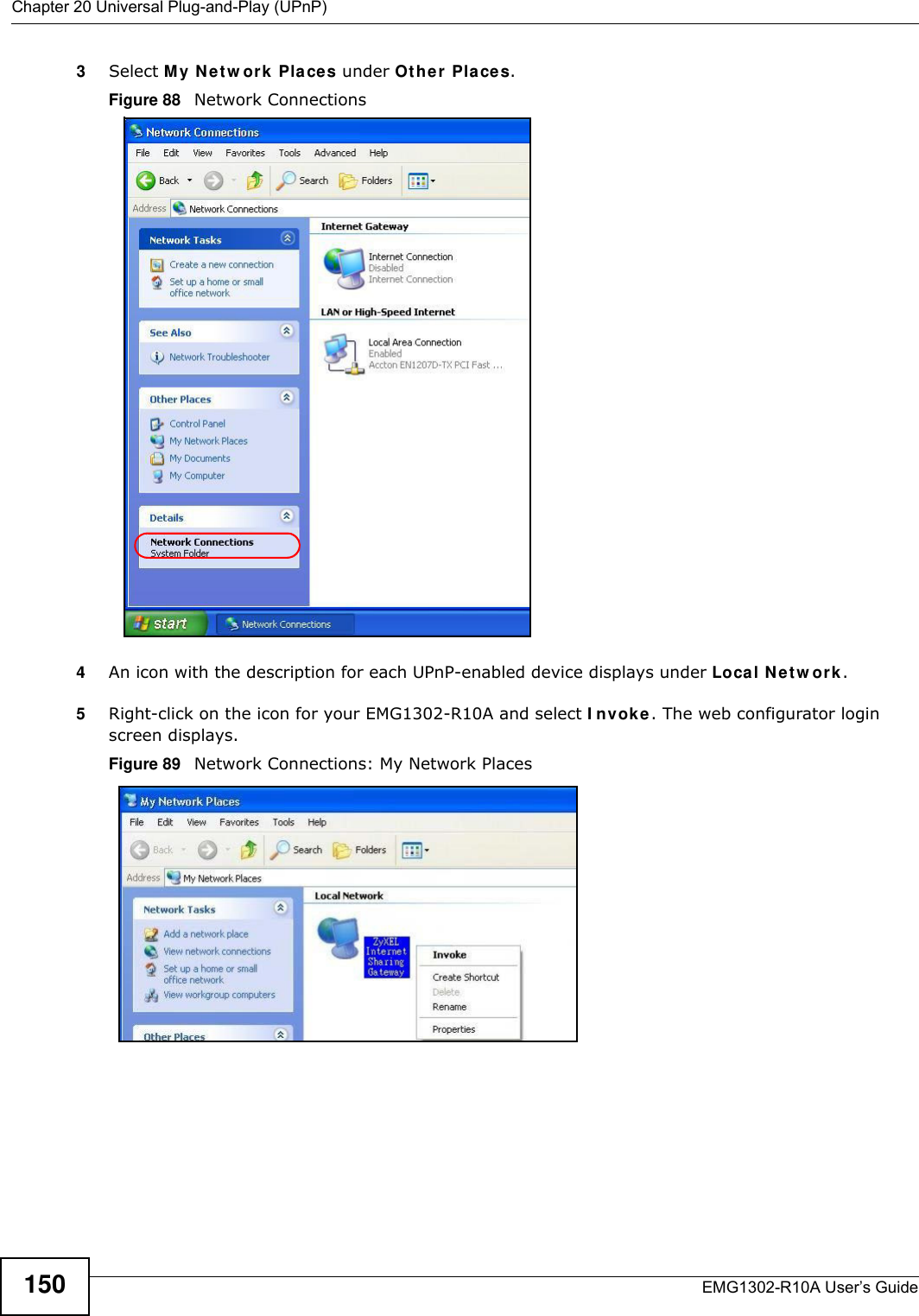
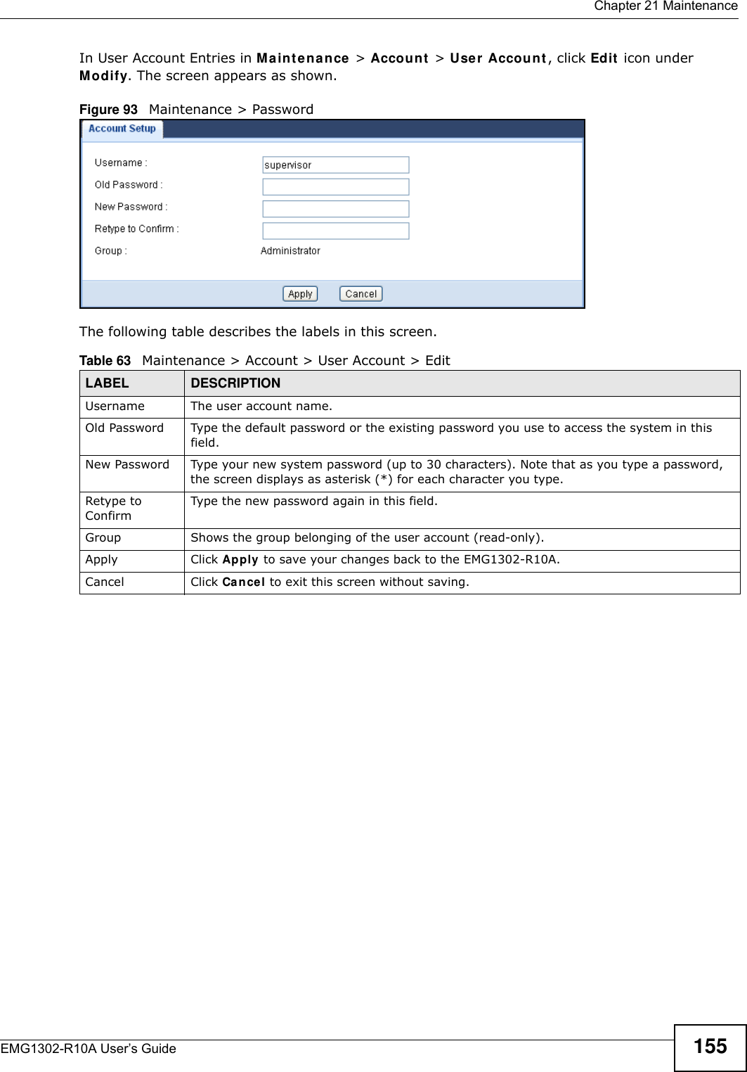
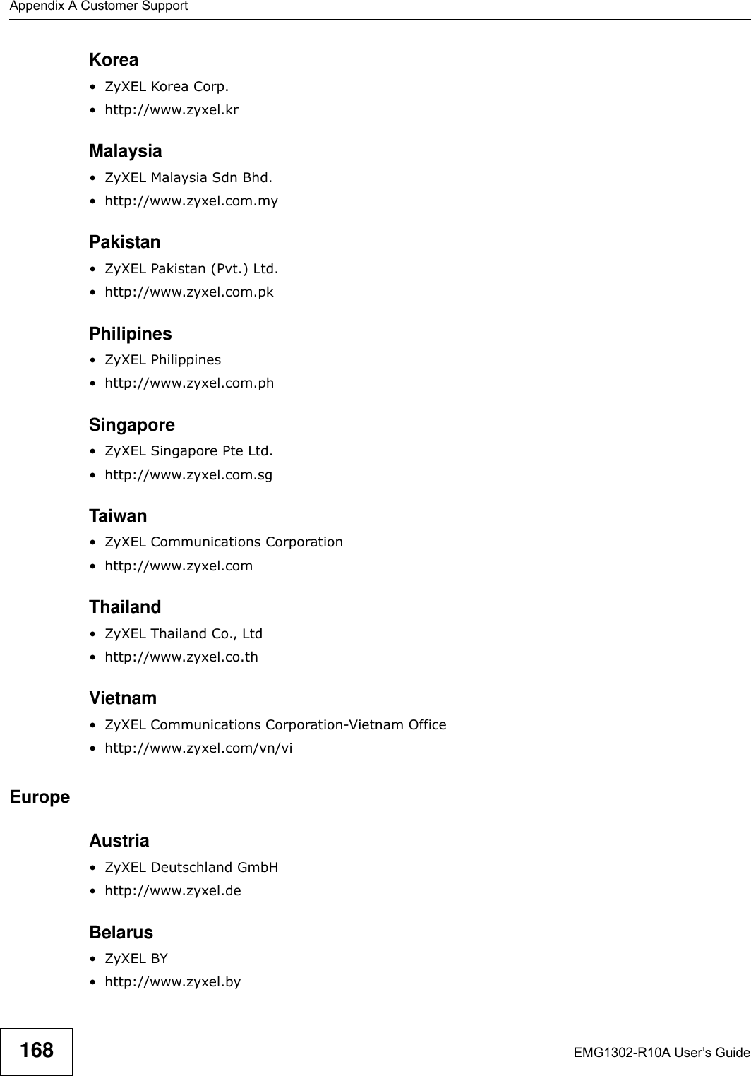
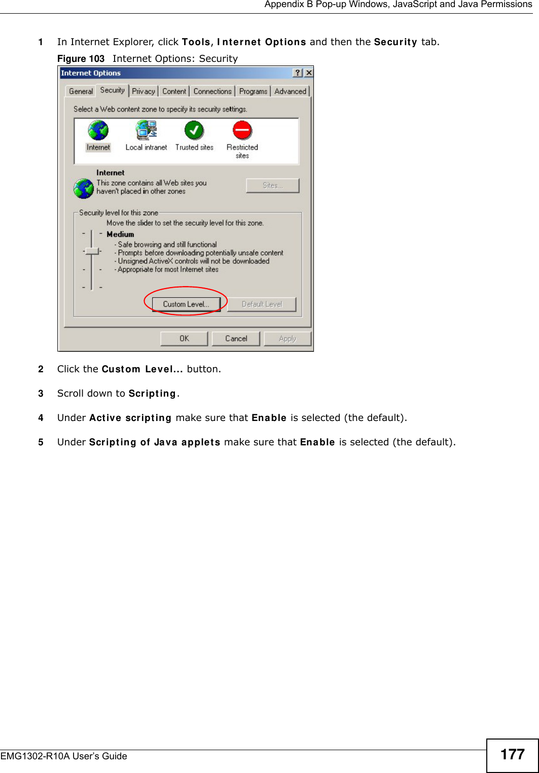
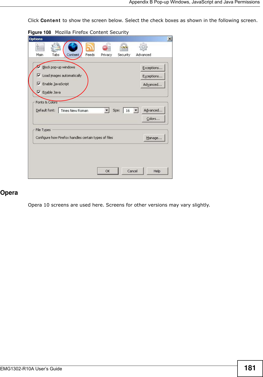
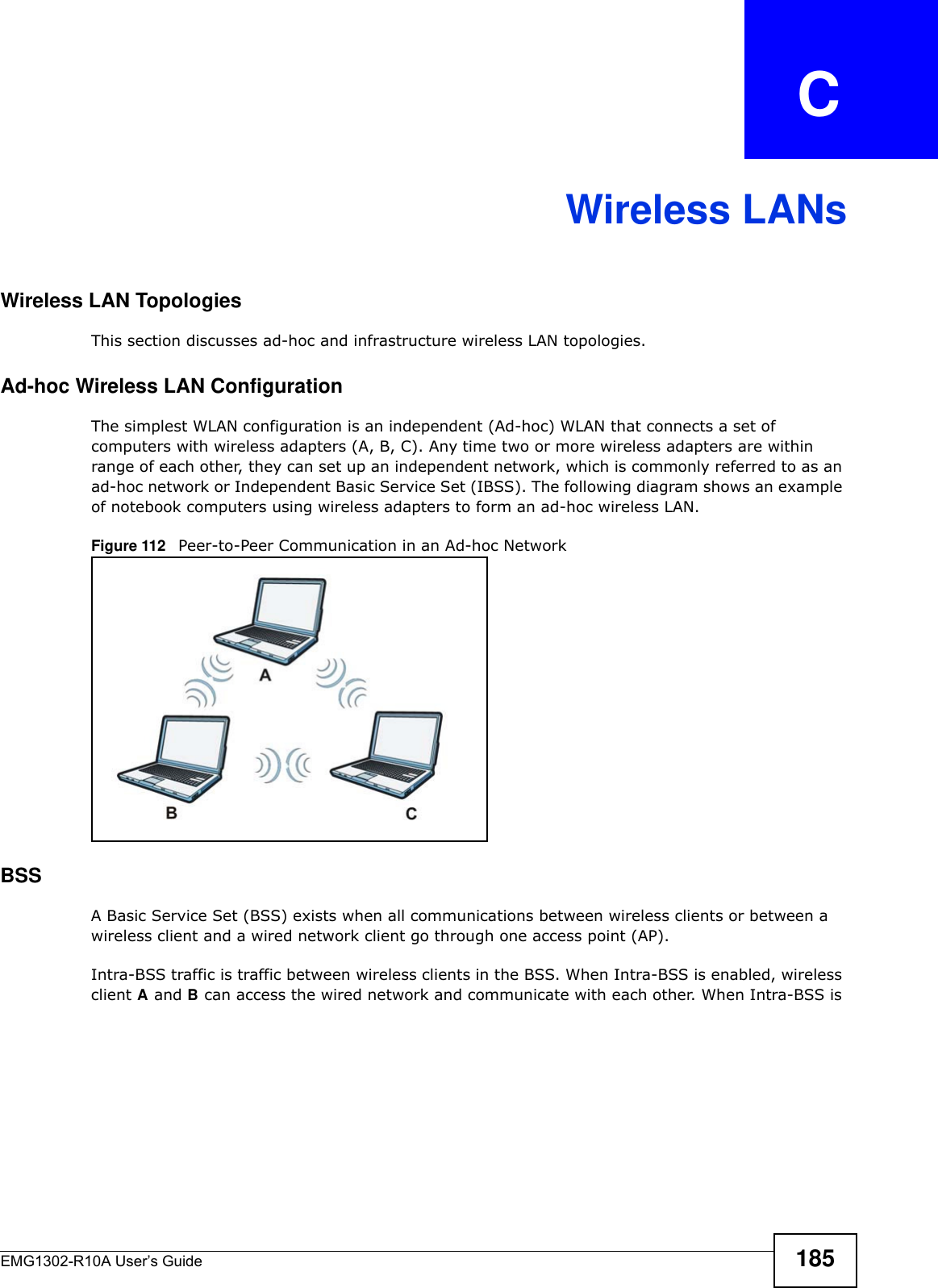
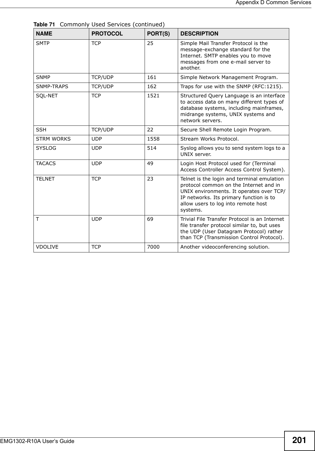
![Appendix E Legal InformationEMG1302-R10A User’s Guide206National RestrictionsThis product may be used in all EU countries (and other countries following the EU directive 1999/5/EC) without any limitation except for the countries mentioned below:Ce produit peut être utilisé dans tous les pays de l’UE (et dans tous les pays ayant transposés la directive 1999/5/CE) sans aucune limitation, excepté pour les pays mentionnés ci-dessous:Questo prodotto è utilizzabile in tutte i paesi EU (ed in tutti gli altri paesi che seguono le direttive EU 1999/5/EC) senza nessuna limitazione, eccetto per i paesii menzionati di seguito:Das Produkt kann in allen EU Staaten ohne Einschränkungen eingesetzt werden (sowie in anderen Staaten die der EU Direktive 1995/5/CE folgen) mit Außnahme der folgenden aufgeführten Staaten:In the majority of the EU and other European countries, the 2, 4- and 5-GHz bands have been made available for the use of wireless local area networks (LANs). Later in this document you will find an overview of countries inwhich additional restrictions or requirements or both are applicable.The requirements for any country may evolve. ZyXEL recommends that you check with the local authorities for the latest status of their national regulations for both the 2,4- and 5-GHz wireless LANs.The following countries have restrictions and/or requirements in addition to those given in the table labeled “Overview of Regulatory Requirement s for Wireless LANs”:.Belgium[Slovenian] ZyXEL izjavlja, da je ta oprema v skladu z bistvenimi zahtevami in ostalimi relevantnimi določili direktive 1999/5/EC.[Slovak] ZyXEL týmto vyhlasuje, že zariadenia spĺňa základné požiadavky a všetky príslušné ustanovenia Smernice 1999/5/EC.[Finnish] ZyXEL vakuuttaa täten että laitteet tyyppinen laite on direktiivin 1999/5/EY oleellisten vaatimusten ja sitä koskevien direktiivin muiden ehtojen mukainen.[Swedish] Härmed intygar ZyXEL att denna utrustning står I överensstämmelse med de väsentliga egenskapskrav och övriga relevanta bestämmelser som framgår av direktiv 1999/5/EC.[Bulgarian] С я ZyXEL , ч я 1999/5/C.[Icelandic] Hér með lýsir, ZyXEL því yfir að þessi búnaður er í samræmi við grunnkröfur og önnur viðeigandi ákvæði tilskipunar 1999/5/EC.[Norwegian] Erklærer herved ZyXEL at dette utstyret er I samsvar med de grunnleggende kravene og andre relevante bestemmelser I direktiv 1999/5/EF.[Romanian] Prin prezenta, ZyXEL declară că acest echipament este în conformitate cu cerinţele esenţiale şi alte prevederi relevante ale Directivei 1999/5/EC.Overview of Regulatory Requirements for Wireless LANs Frequency Band (MHz) Max Power Level(EIRP)1 (mW) Indoor ONLY Indoor and Outdoor 2400-2483.5 100 V 5150-5350 200 V 5470-5725 1000 V](https://usermanual.wiki/ZyXEL-Communications/EMG1302R10A/User-Guide-2198186-Page-206.png)