ZyXEL Communications EMG3415-B10A Dual-Band Wireless AC/N Gigabit Ethernet Gateway User Manual Book
ZyXEL Communications Corporation Dual-Band Wireless AC/N Gigabit Ethernet Gateway Book
UserManual.wiki
>
ZyXEL Communications
>
EMG3415-B10A User Manual
>
Users Manual-2
Contents
1.
Users Manual-1
2.
Users Manual-2
Users Manual-2
Navigation menu
Upload a User Manual
Namespaces
Wiki Guide
HTML
PDF
Info
Views
User Manual
Discussion / Help
Navigation
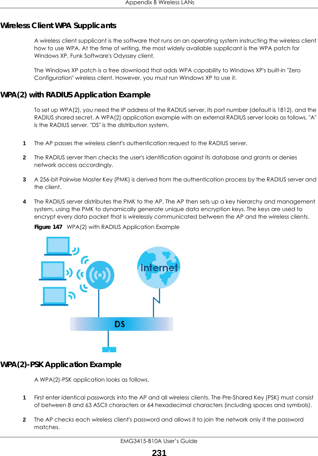
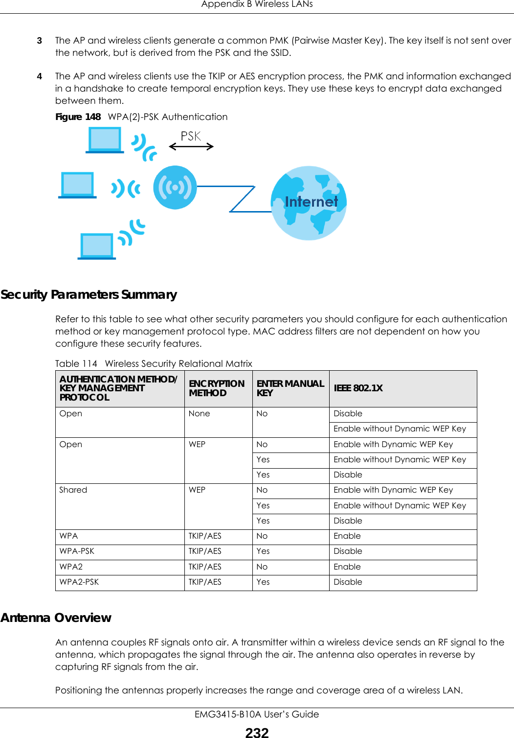
![Chapter 34 TroubleshootingEMG3415-B10A User’s Guide212I can see the Login screen, but I cannot log in to the EMG.7You cannot log in to the web configurator while someone is using Telnet to access the EMG. Log out of the EMG in the other session, or ask the person who is logged in to log out. 8Turn the EMG off and on. 9If this does not work, you have to reset the device to its factory defaults. See Section 34.1 on page 210.I cannot Telnet to the EMG.See the troubleshooting suggestions for I cannot see or access the Login screen in the web configurator. Ignore the suggestions about your browser.I cannot use FTP to upload / download the configuration file. / I cannot use FTP to upload new firmware.See the troubleshooting suggestions for I cannot see or access the Login screen in the web configurator. Ignore the suggestions about your browser.34.3 Internet AccessI cannot access the Internet.1Check the hardware connections, and make sure the LEDs are behaving as expected. See the Quick Start Guide and Section 1.5 on page 15.2Make sure you entered your ISP account information correctly in the Network Setting > Broadband screen. These fields are case-sensitive, so make sure [Caps Lock] is not on. 3If you are trying to access the Internet wirelessly, make sure that you enabled the wireless LAN in the EMG and your wireless client and that the wireless settings in the wireless client are the same as the settings in the EMG.4Disconnect all the cables from your device and reconnect them. 5If the problem continues, contact your ISP.](https://usermanual.wiki/ZyXEL-Communications/EMG3415-B10A.Users-Manual-2/User-Guide-3470596-Page-8.png)