ZyXEL Communications EMG3415-B10A Dual-Band Wireless AC/N Gigabit Ethernet Gateway User Manual Book
ZyXEL Communications Corporation Dual-Band Wireless AC/N Gigabit Ethernet Gateway Book
UserManual.wiki
>
ZyXEL Communications
>
EMG3415-B10A User Manual
>
Users Manual-1
Contents
1.
Users Manual-1
2.
Users Manual-2
Users Manual-1
Navigation menu
Upload a User Manual
Namespaces
Wiki Guide
HTML
PDF
Info
Views
User Manual
Discussion / Help
Navigation
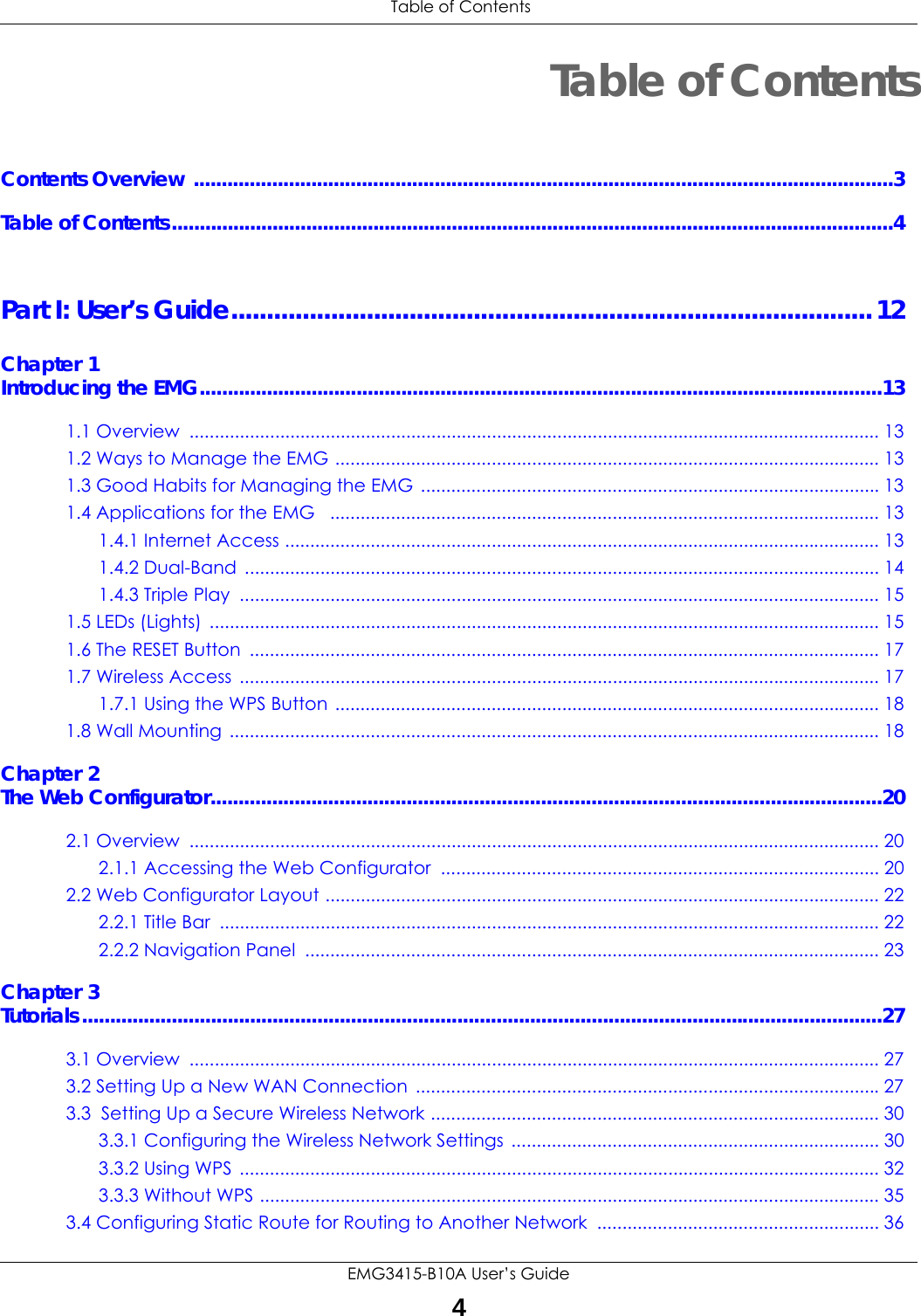
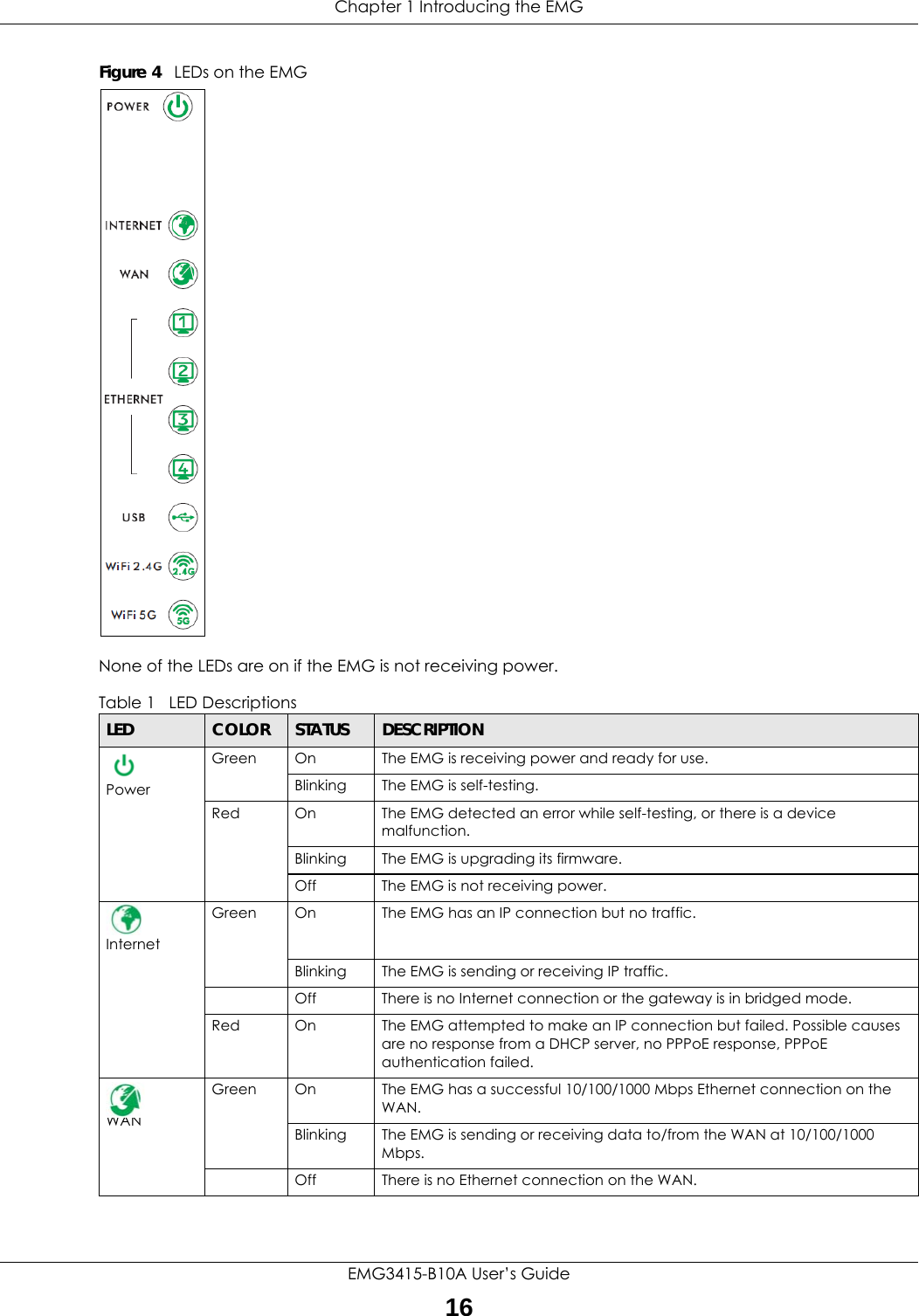
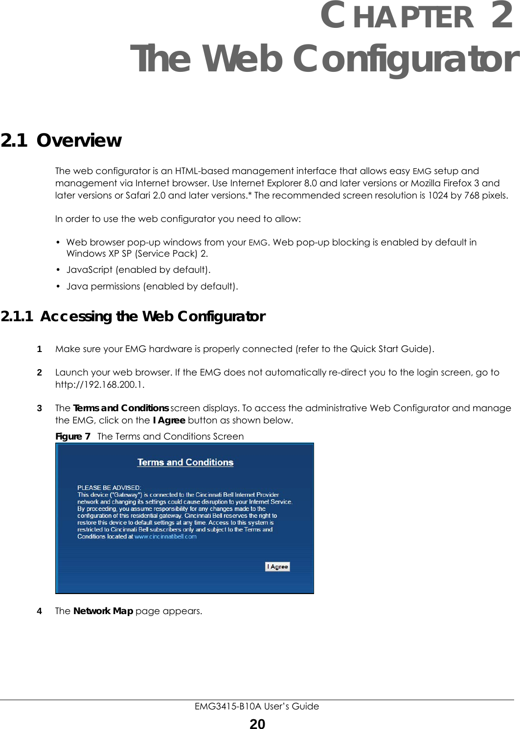

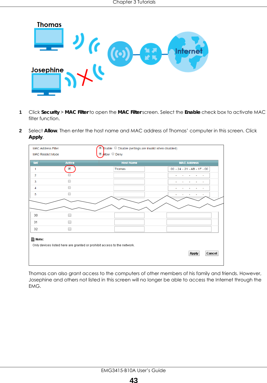
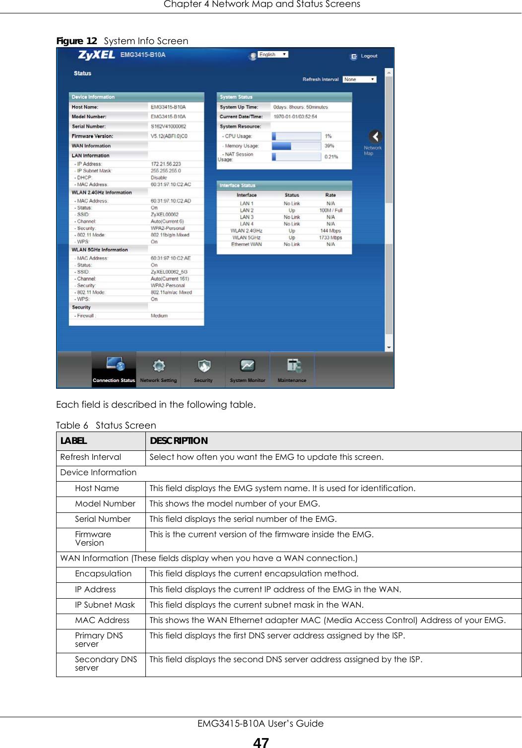
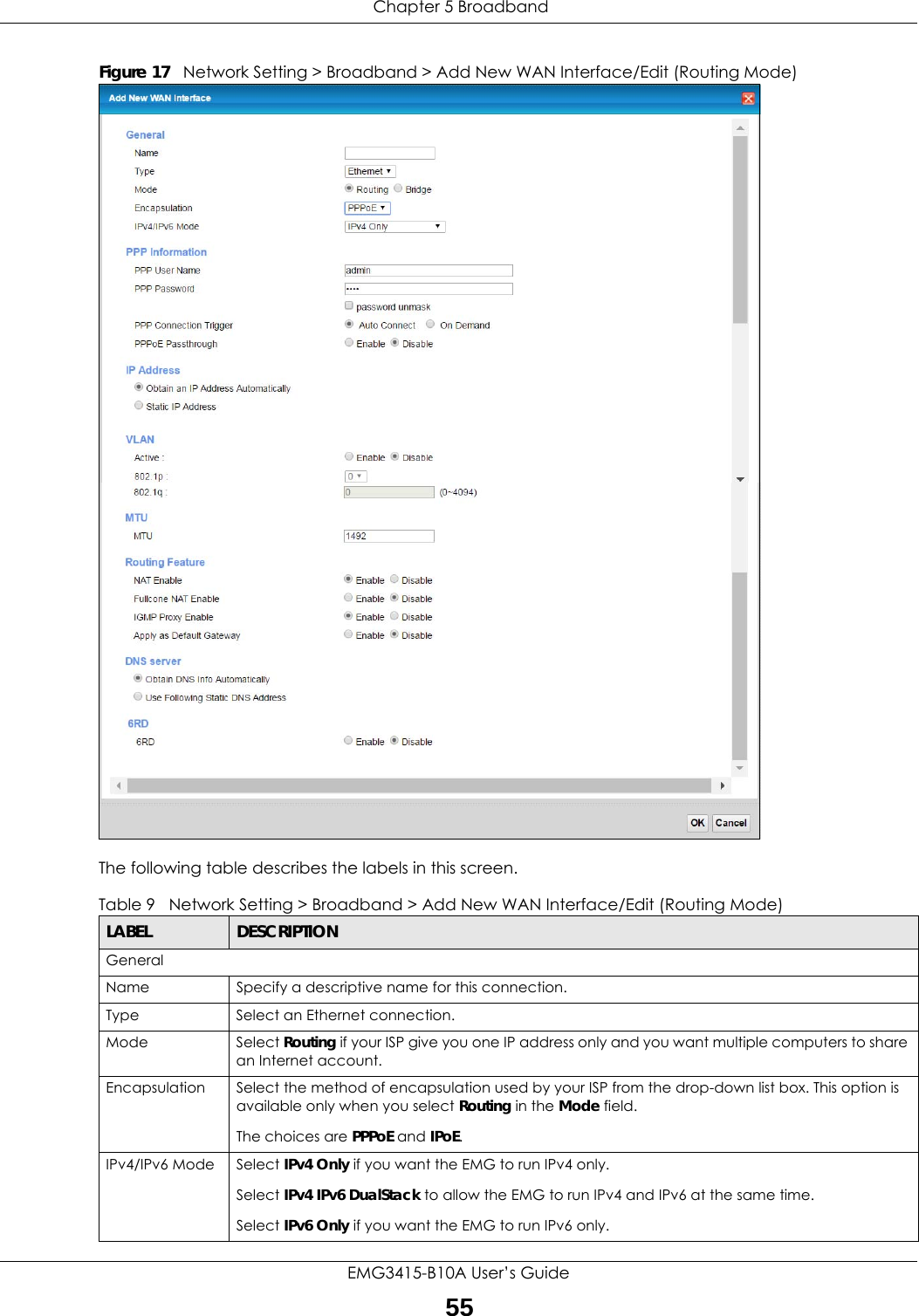
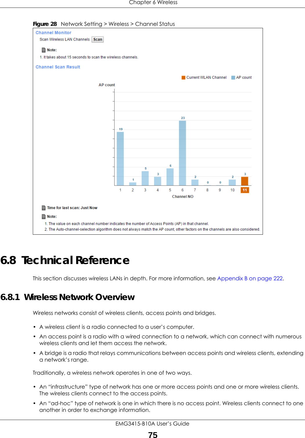
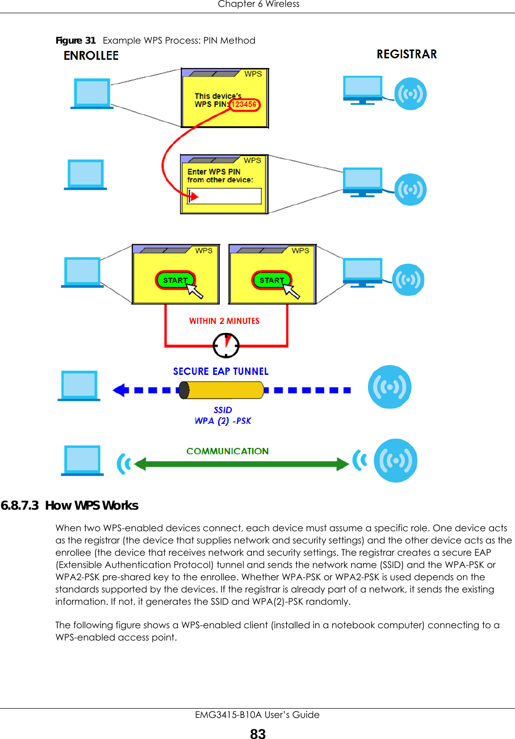
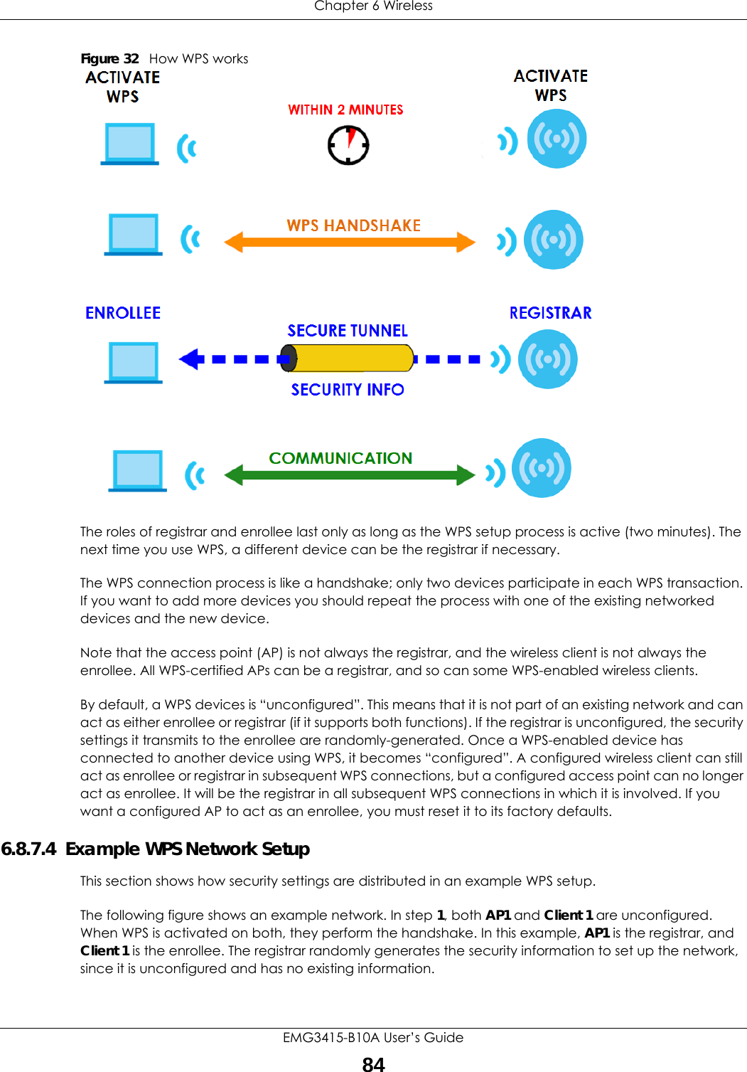
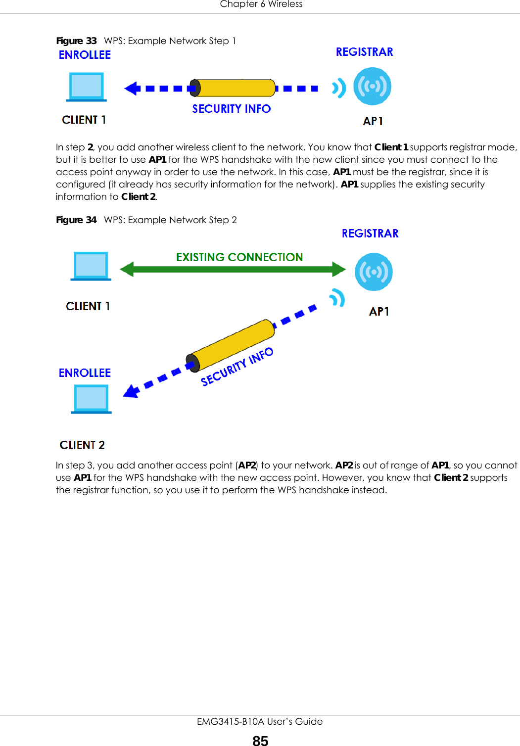
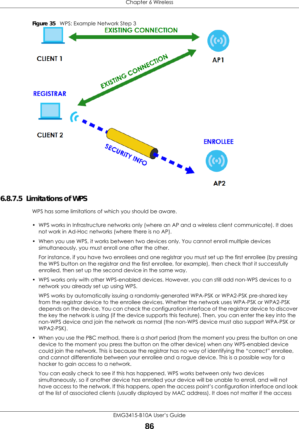
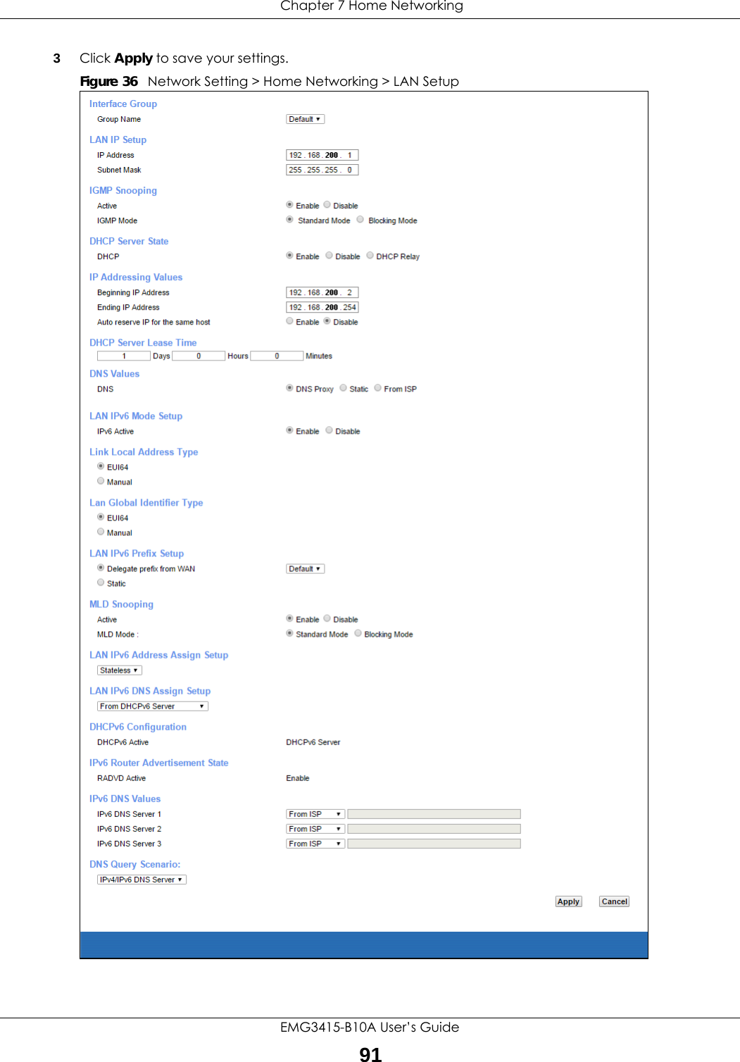
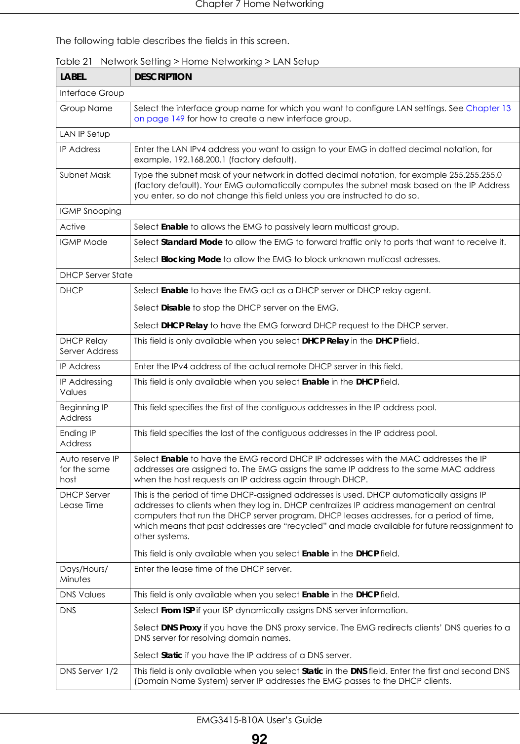
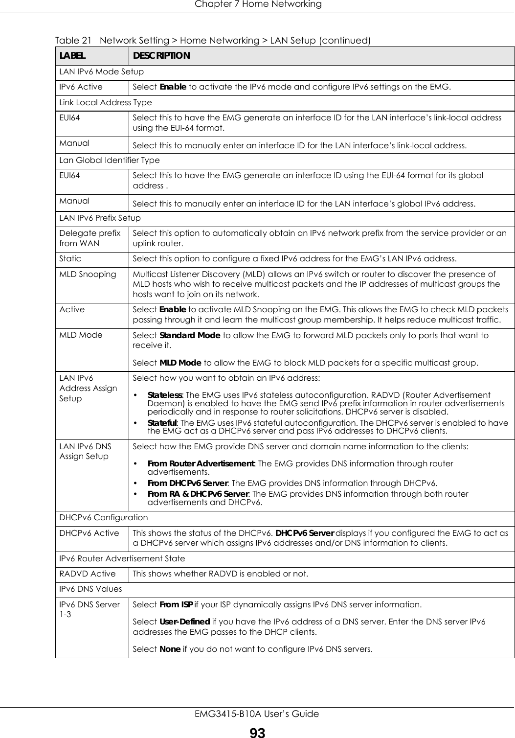
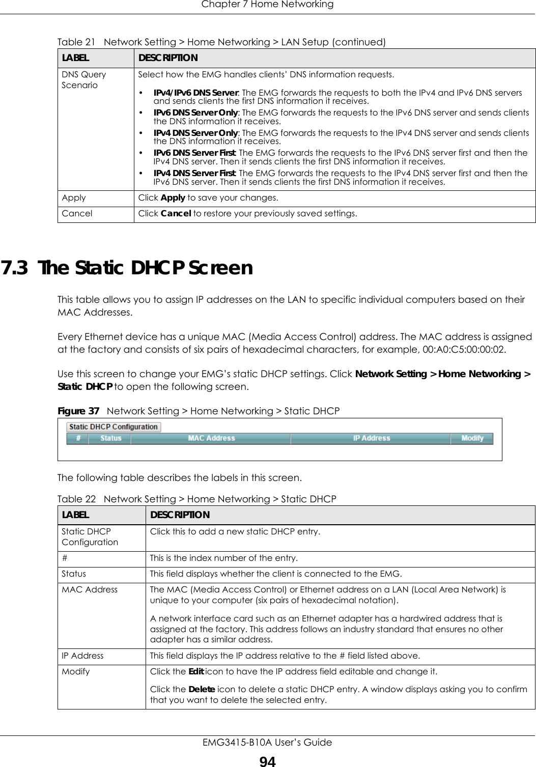
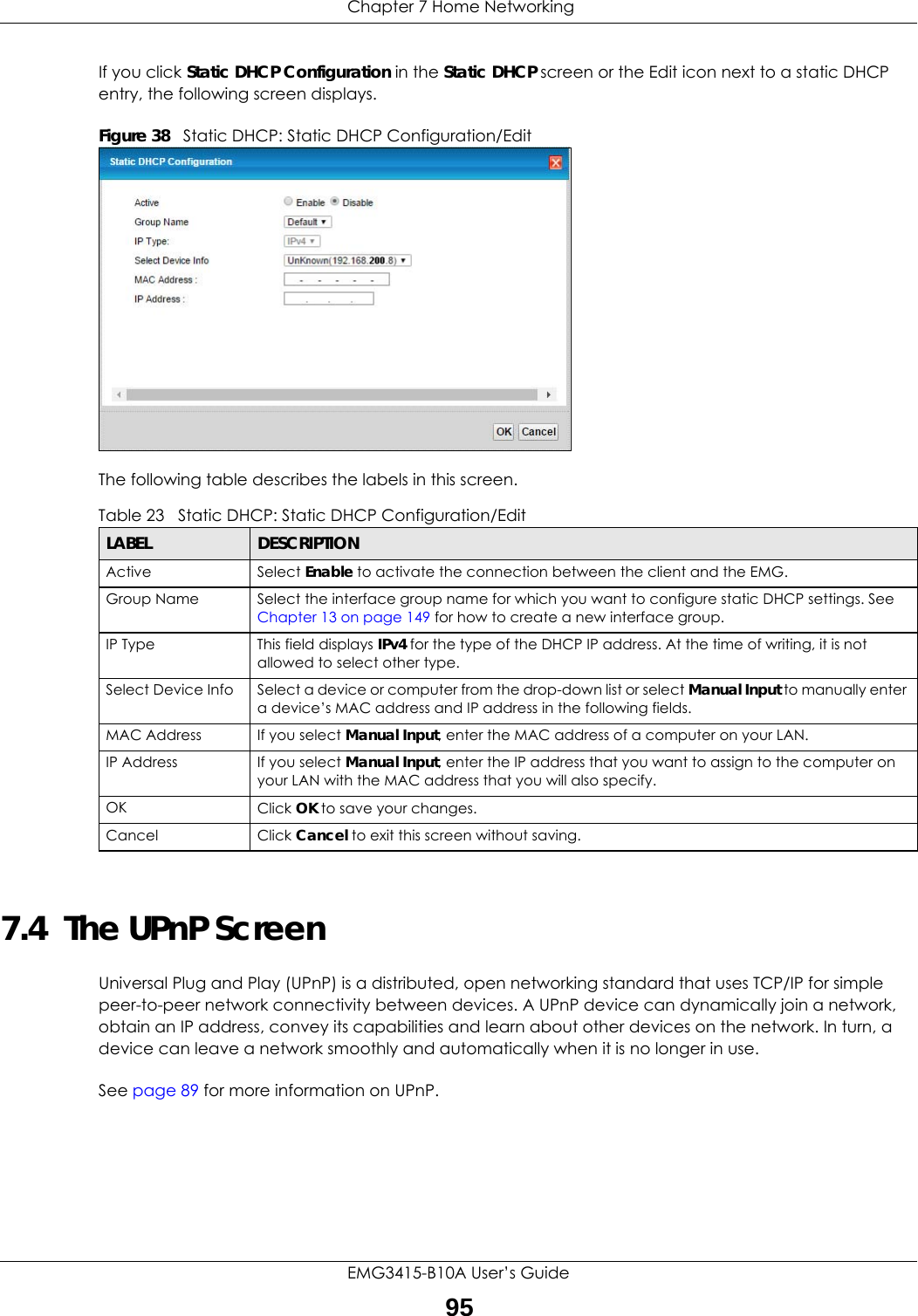
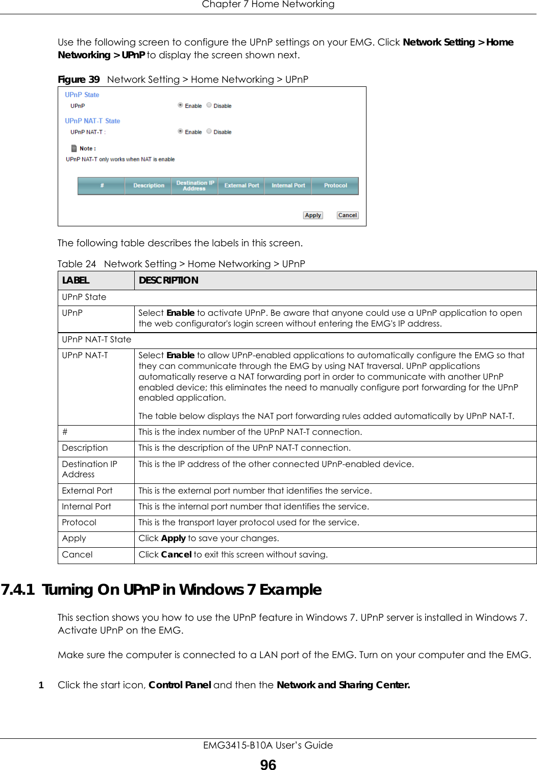
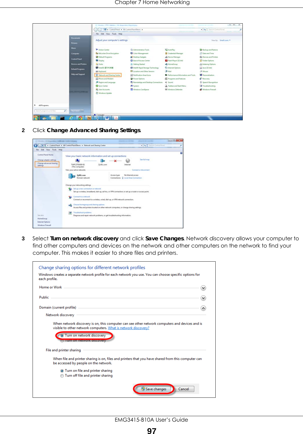
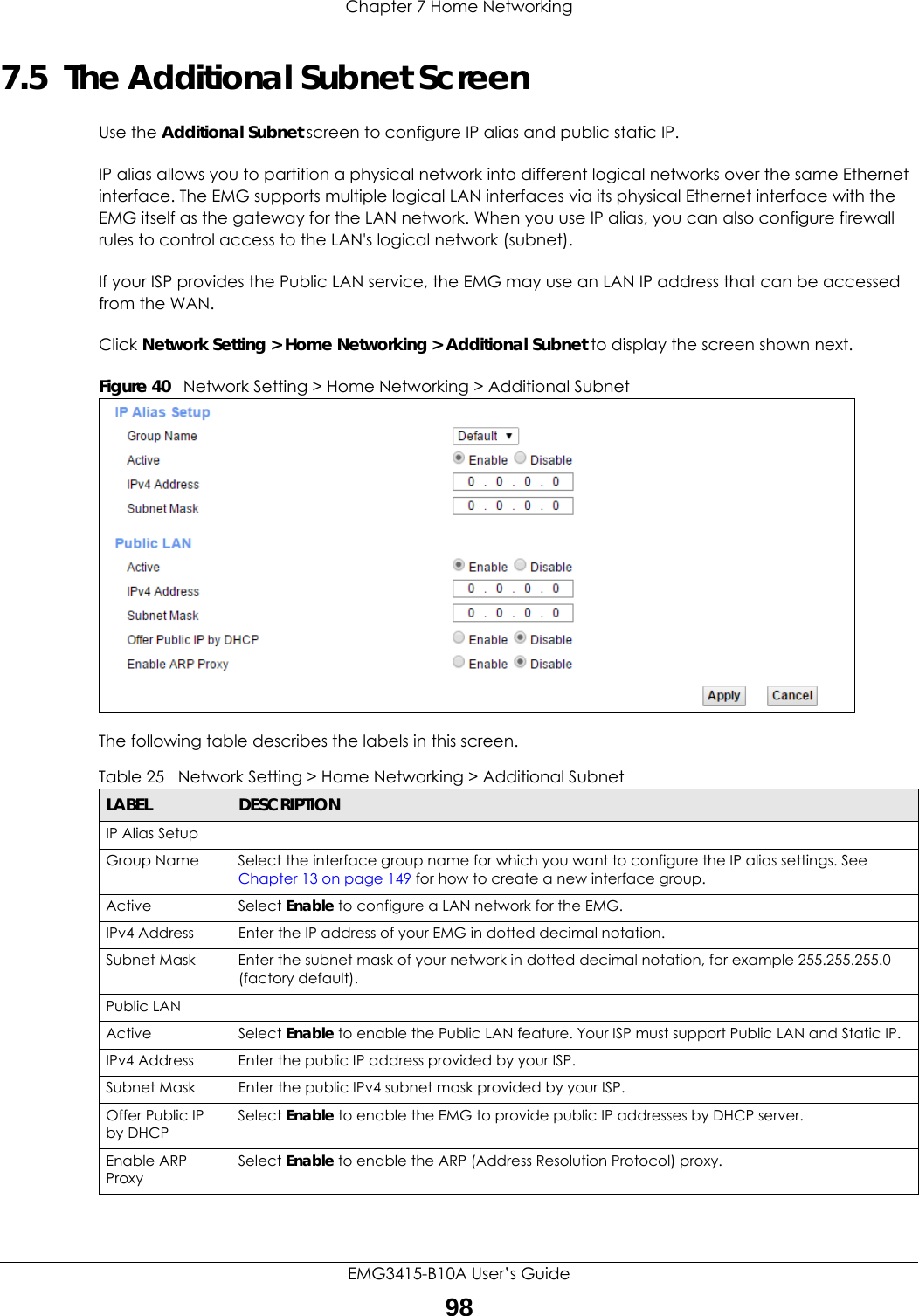
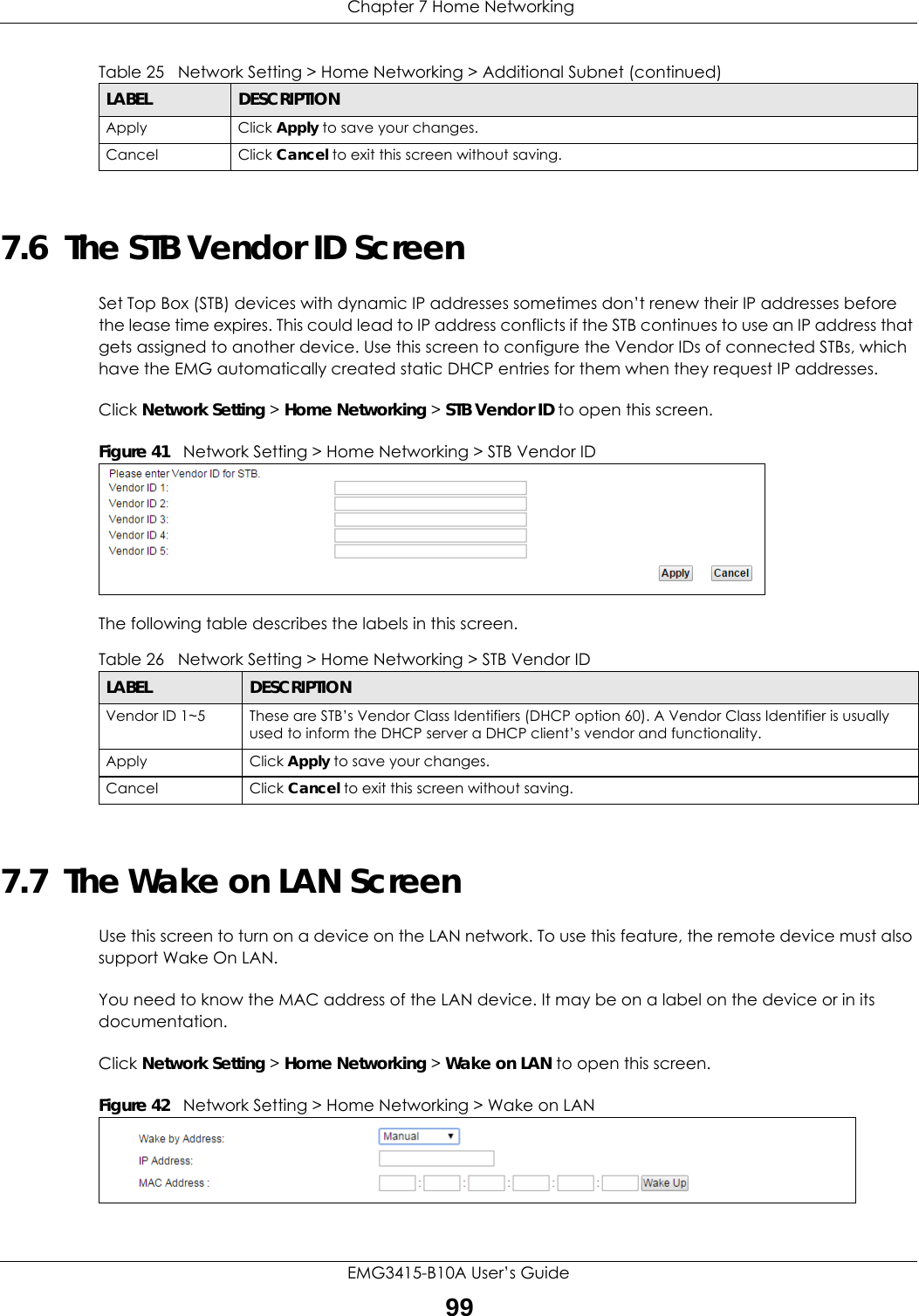
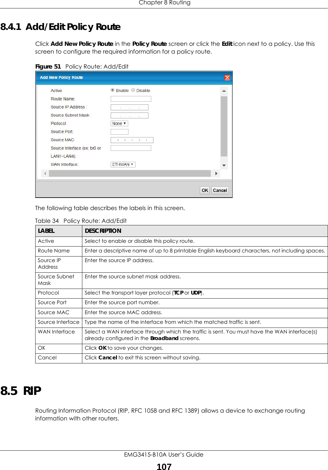
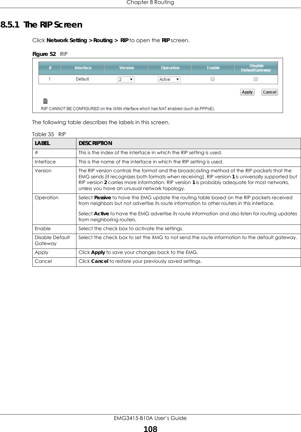
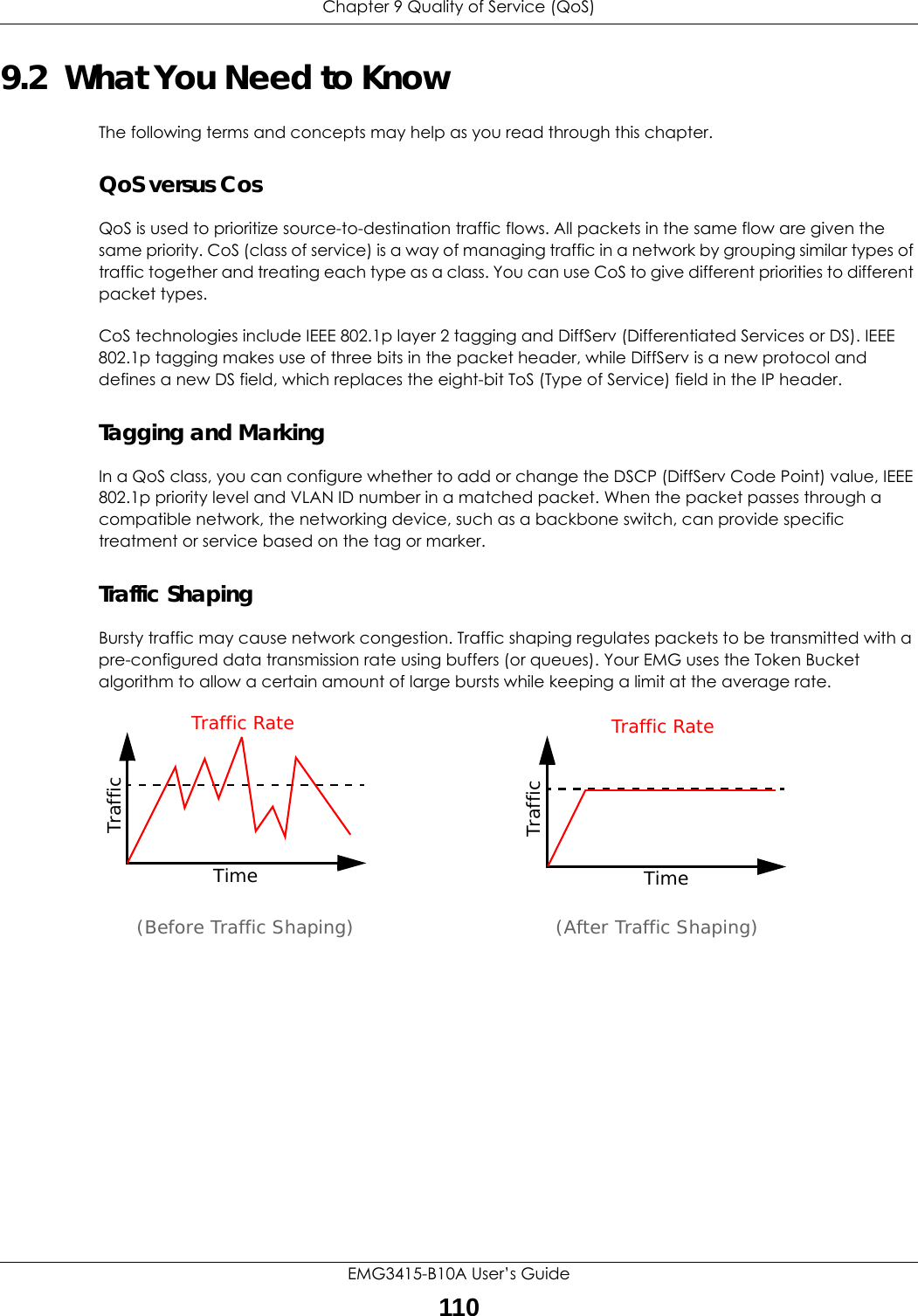
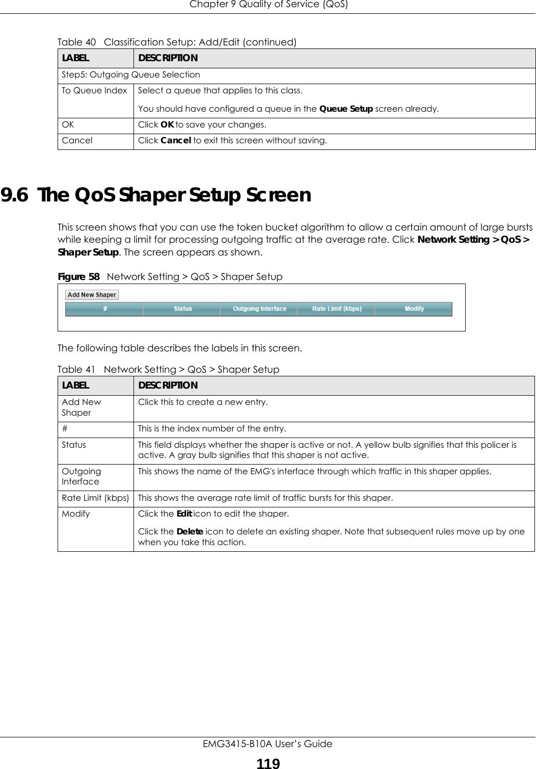
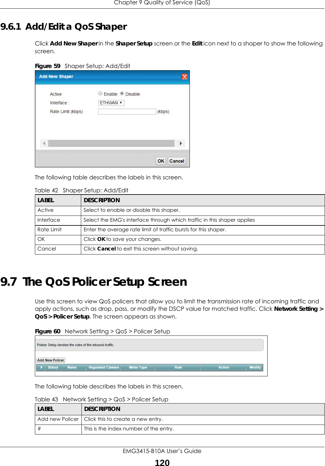
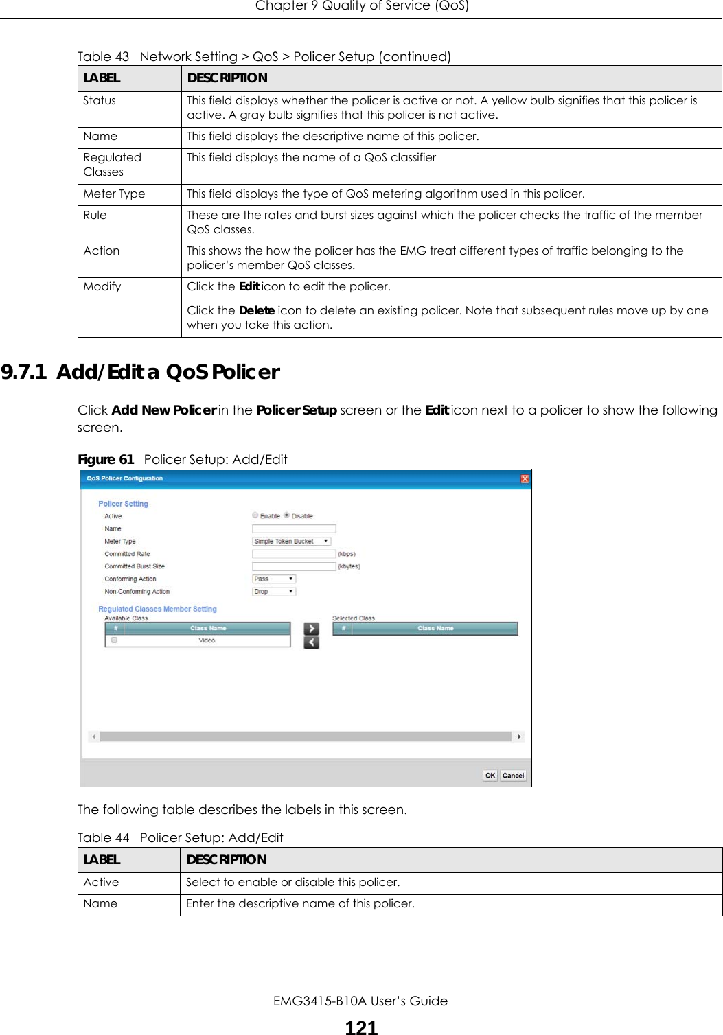
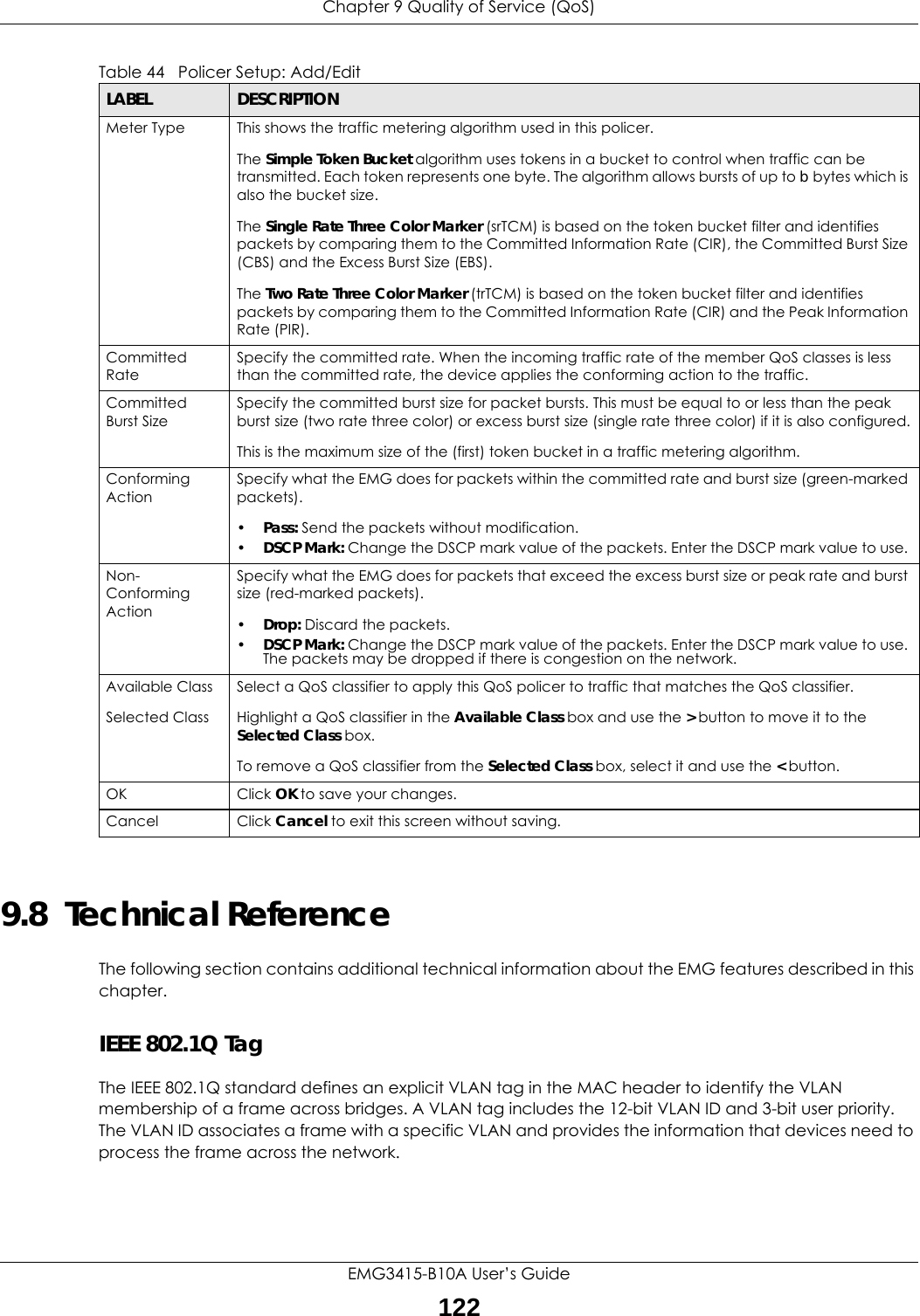
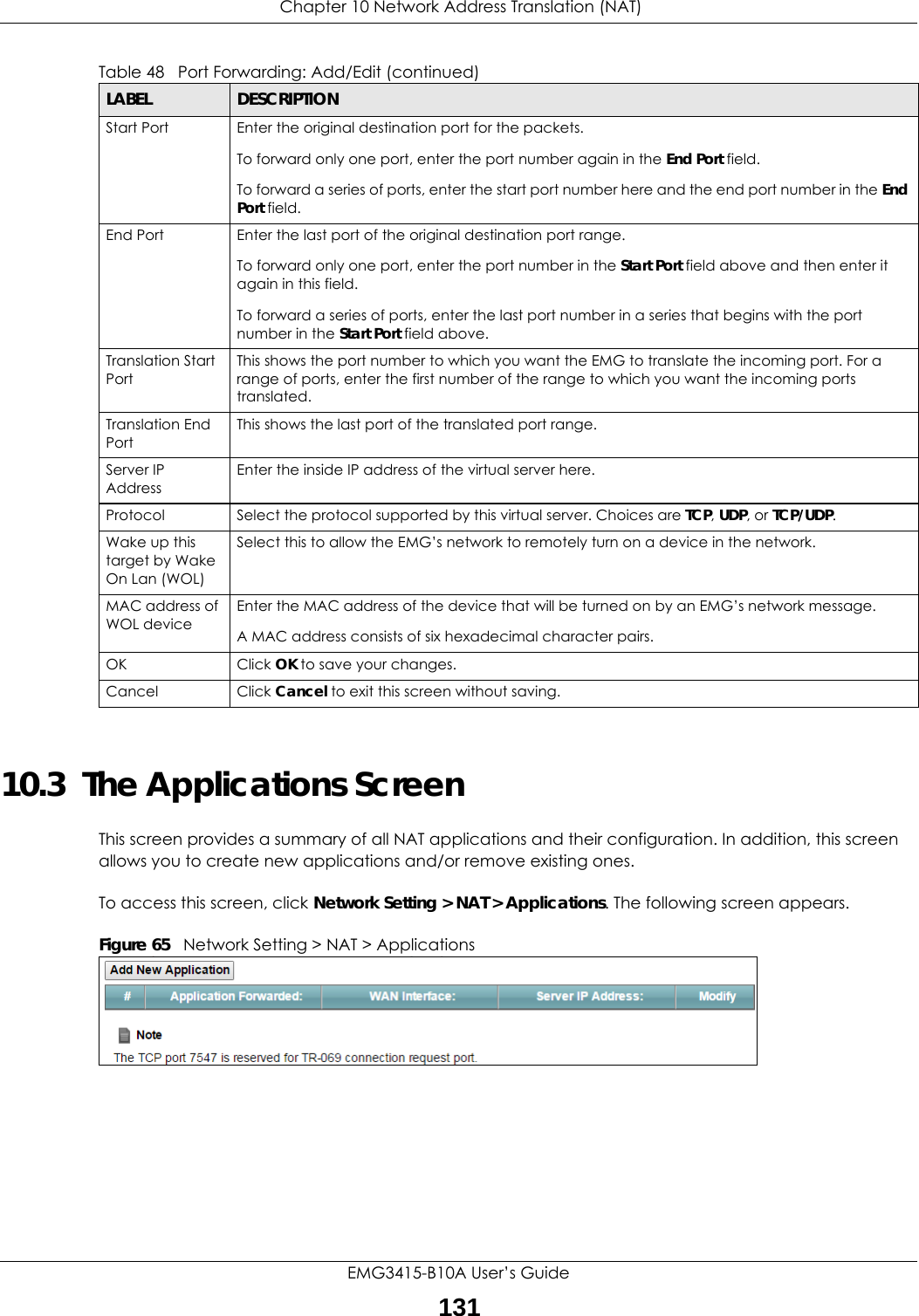
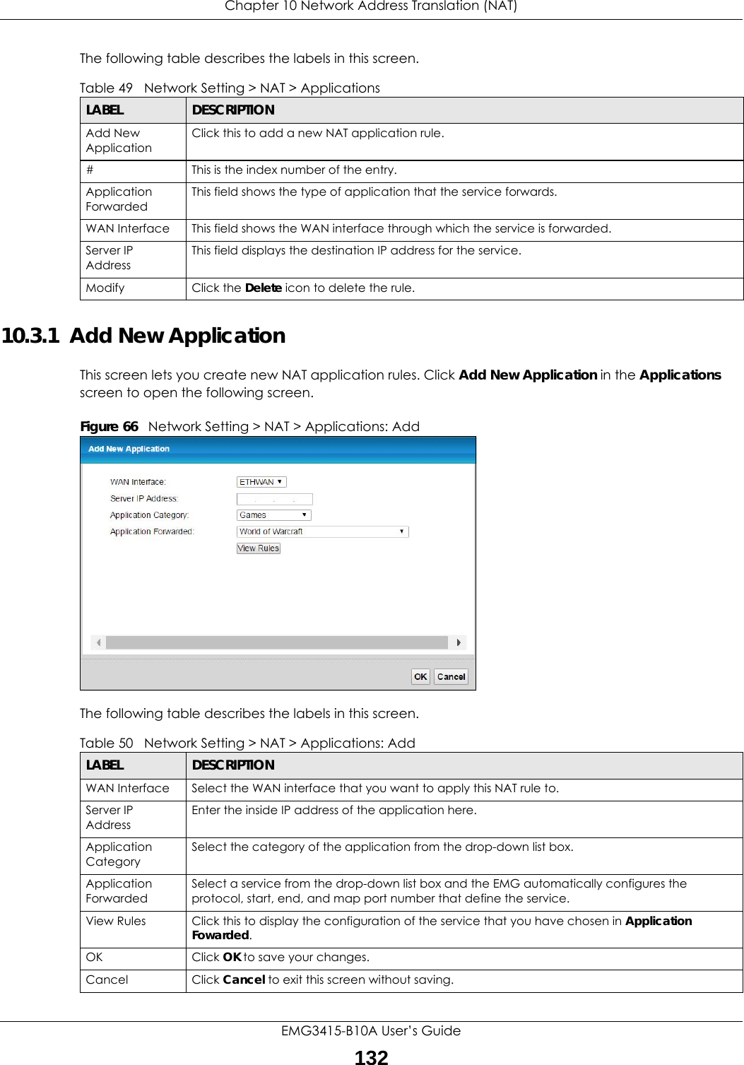
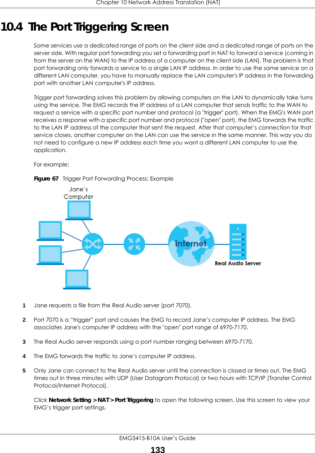
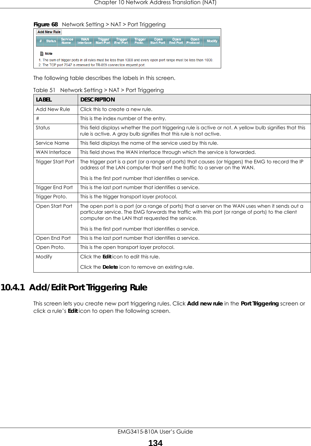
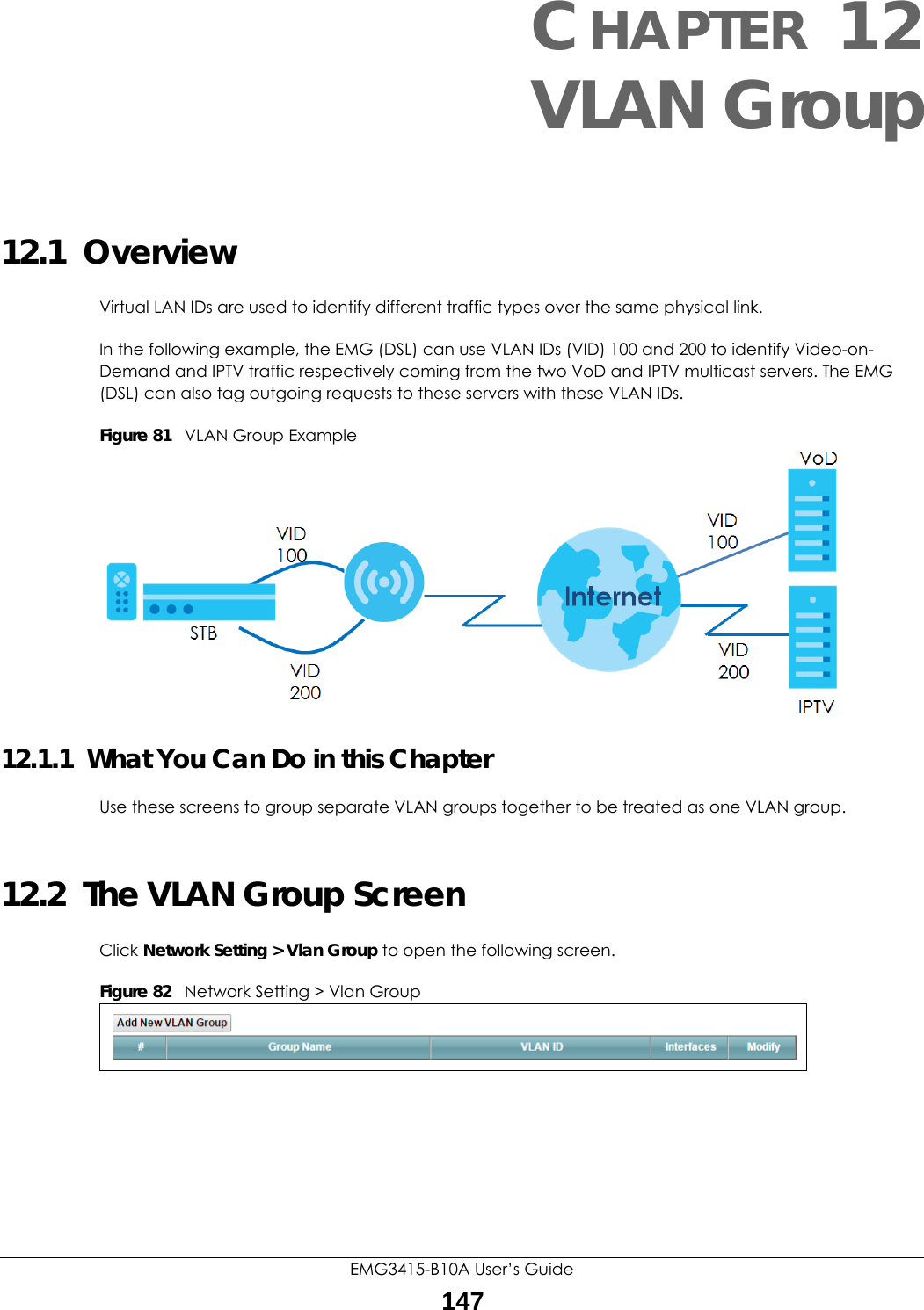
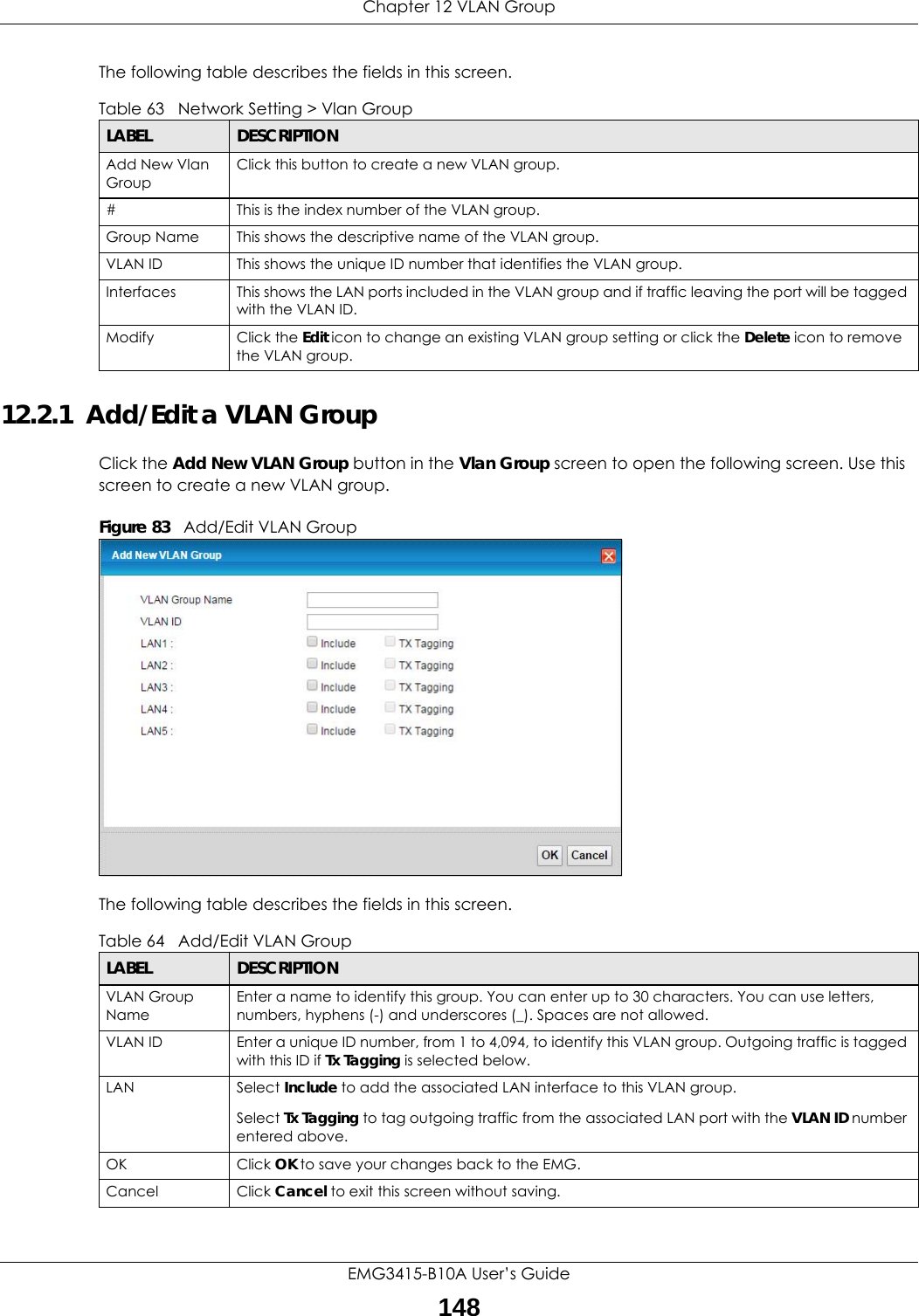
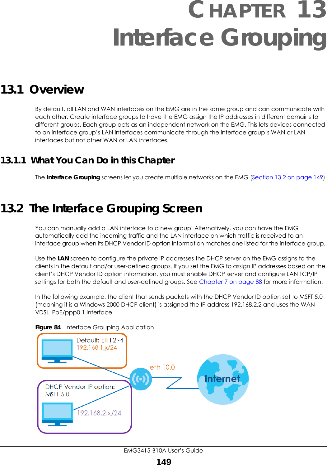
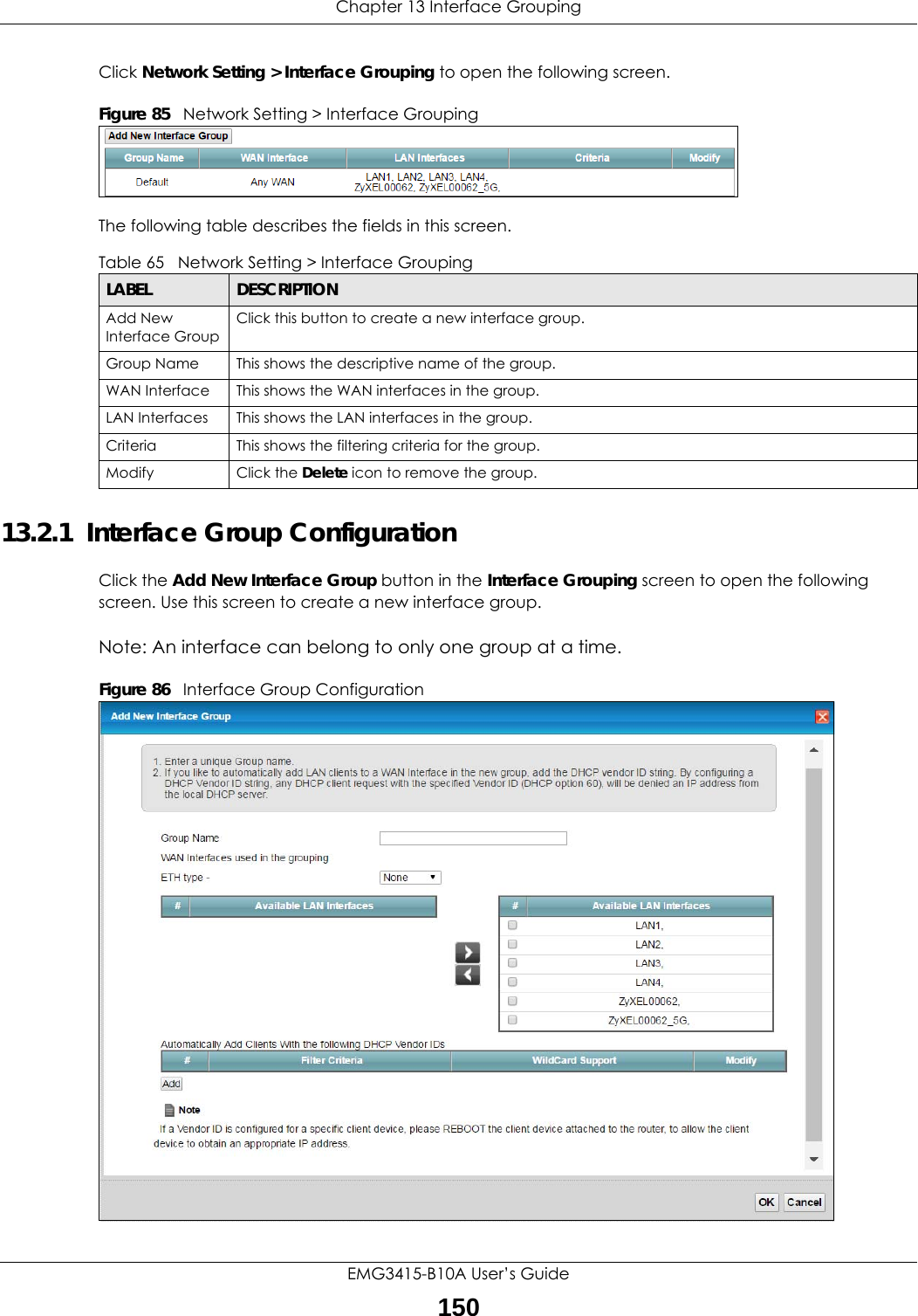
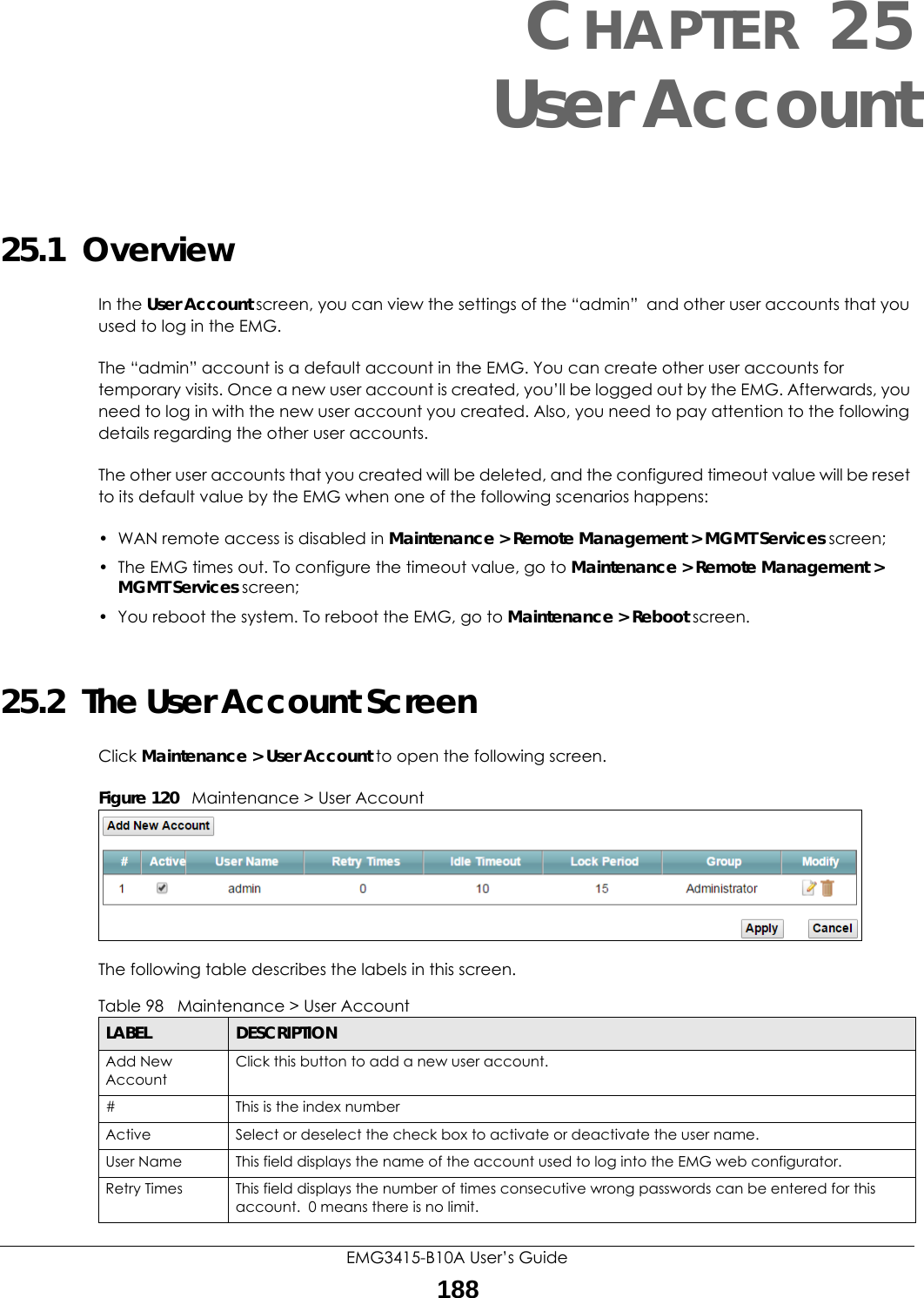
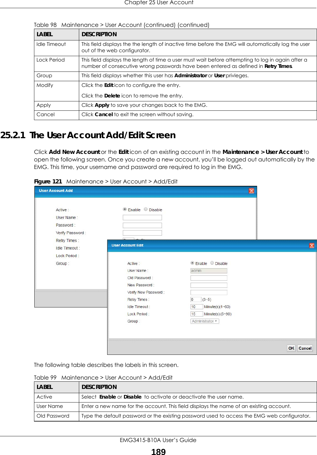
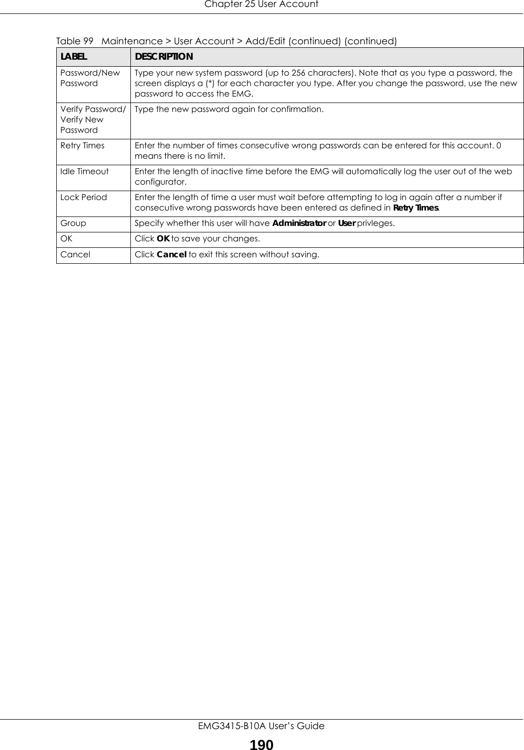
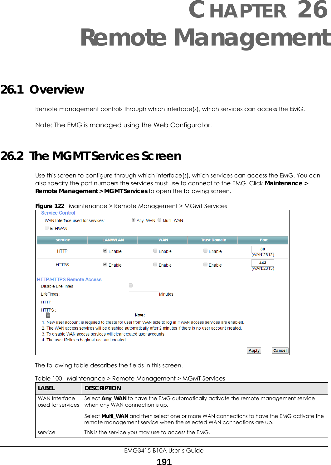
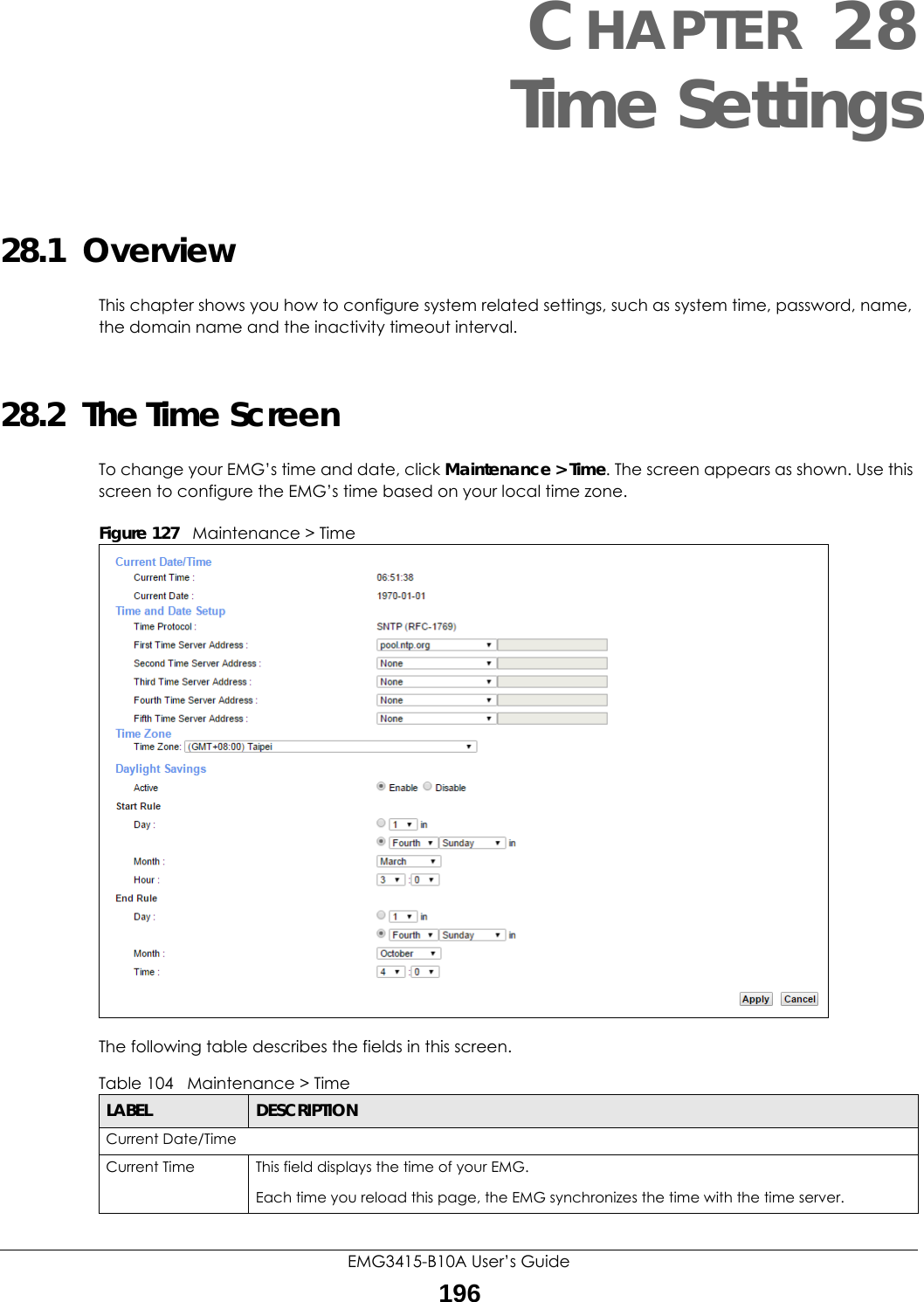
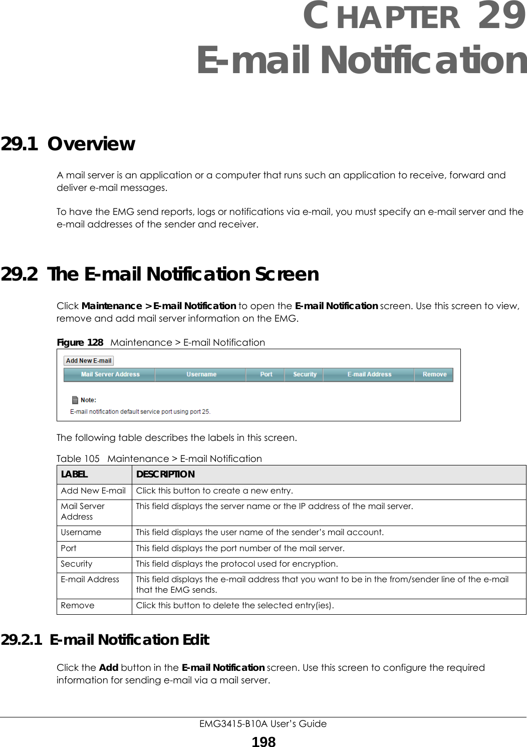
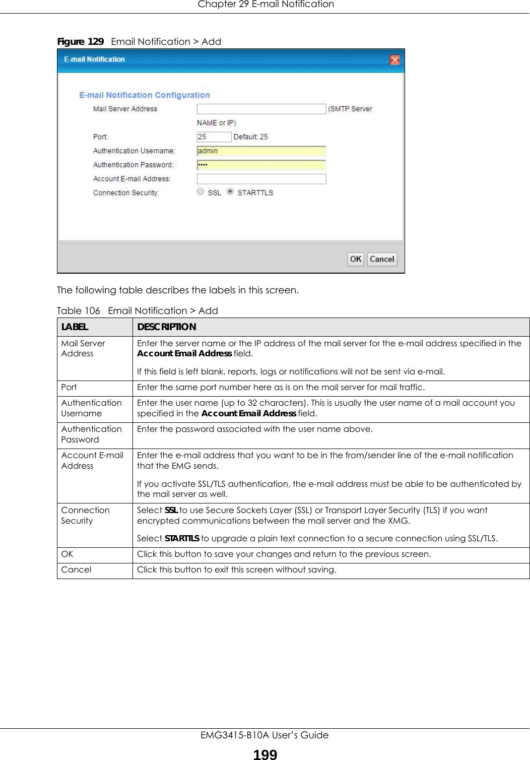
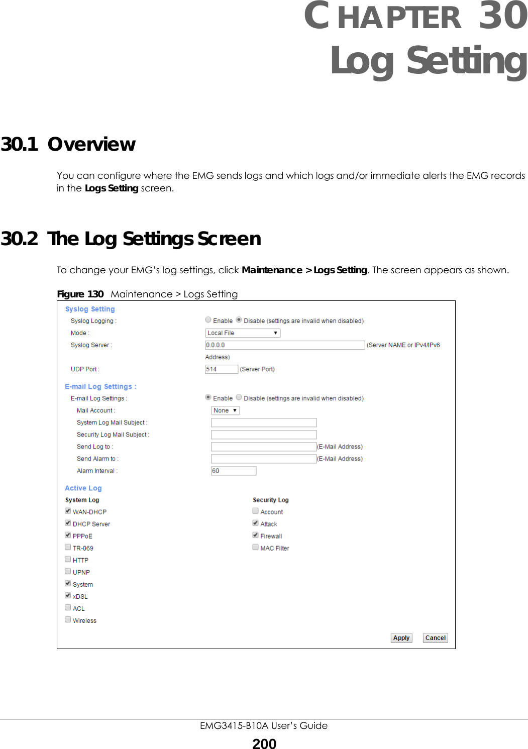
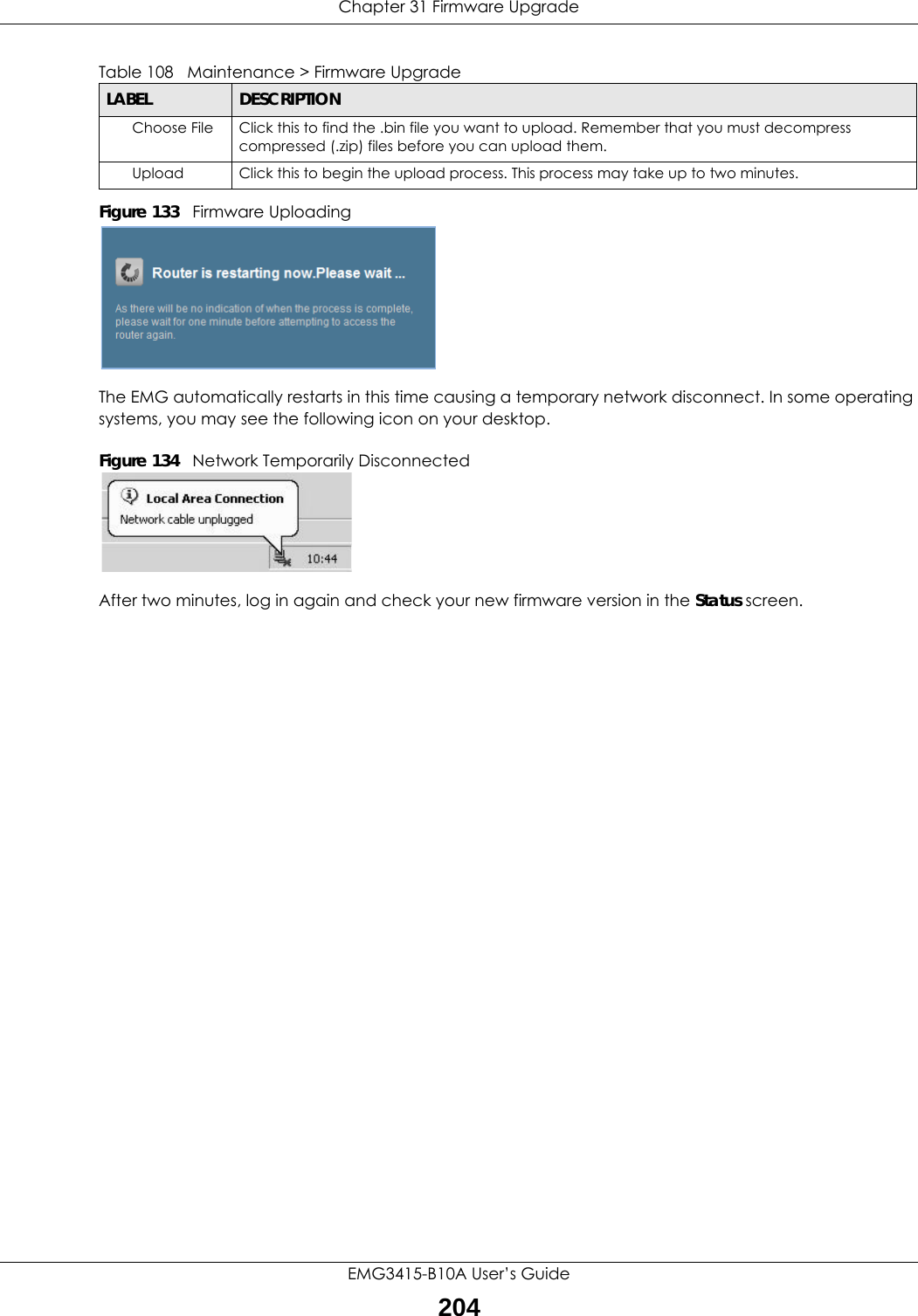
![Chapter 3 TutorialsEMG3415-B10A User’s Guide42• Enter the user name (UserName1) and password (12345).Click Apply.3.6.3 Testing the DDNS SettingNow you should be able to access the EMG from the Internet. To test this:1Open a web browser on the computer (using the IP address a.b.c.d) that is connected to the Internet.2Type http://zyxelrouter.dyndns.org and press [Enter].3The EMG’s login page should appear. You can then log into the EMG and manage it.3.7 Configuring the MAC Address FilterThomas noticed that his daughter Josephine spends too much time surfing the web and downloading media files. He decided to prevent Josephine from accessing the Internet so that she can concentrate on preparing for her final exams.Josephine’s computer connects wirelessly to the Internet through the EMG. Thomas decides to use the Security > MAC Filter screen to grant wireless network access to his computer but not to Josephine’s computer.](https://usermanual.wiki/ZyXEL-Communications/EMG3415-B10A.Users-Manual-1/User-Guide-3470594-Page-42.png)