ZyXEL Communications EMG3425Q10A Simultaneous Dual-Band Wireless AC2200 Gigabit Ethernet Gateway User Manual 1
ZyXEL Communications Corporation Simultaneous Dual-Band Wireless AC2200 Gigabit Ethernet Gateway Users Manual 1
Contents
- 1. Users Manual-1
- 2. Users Manual-2
Users Manual-1

Quick Start Guide
www.zyxel.com
EMG3 4 2 5 - Q1 0 A
Dual-Band Wireless AC/N Gigabit Ethernet Gateway
Version 1.00
Edition 1, 08/2015
Copyright © 2015 ZyXEL Communications Corporation
User’s Guide
Default Login Det a ils
LAN IP Address http://192.168.1.1
(Router Mode)
http://192.168.1.2
(Access Point Mode)
User Name supervisor, admin
Password supervisor, 1234

EMG3425-Q10A User’s Guide
2
IMPORTANT!
READ CAREFULLY BEFORE USE.
KEEP THIS GUIDE FOR FUTURE REFERENCE.
Screenshots and graphics in this book may differ slightly from your product due to differences in
your product firmware or your computer operating system. Every effort has been made to ensure
that the information in this manual is accurate.
Related Documentation
•Quick Start Guide
The Quick Start Guide shows how to connect the EMG3425-Q10A and access the Web
Configurator wizards. It contains information on setting up your network and configuring for
Internet access.
•More Information
Go to su ppo rt .z yx el.com to find other information on the EMG3425-Q10A.

Contents Overview
EMG3425-Q10A User’s Guide
3
Contents Overview
User’s Guide ....................................................................................................................................... 11
Introduction .............................................................................................................................................12
Introducing the Web Configurator ...........................................................................................................19
EMG3425-Q10A Modes ..........................................................................................................................23
Router Mode ...........................................................................................................................................24
Access Point Mode .................................................................................................................................31
Tutorials ..................................................................................................................................................38
Technical Reference ..........................................................................................................................50
Monitor ....................................................................................................................................................51
WAN ........................................................................................................................................................57
Wireless LAN ..........................................................................................................................................68
LAN .........................................................................................................................................................88
DHCP Server ..........................................................................................................................................94
NAT .........................................................................................................................................................99
DDNS ....................................................................................................................................................109
Static Route ........................................................................................................................................... 111
Interface Group ..................................................................................................................................... 114
Firewall .................................................................................................................................................. 117
Content Filtering ....................................................................................................................................122
IPv6 Firewall ..........................................................................................................................................124
Parental Control ....................................................................................................................................127
Bandwidth Management .......................................................................................................................133
Remote Management ............................................................................................................................147
Universal Plug-and-Play (UPnP) ...........................................................................................................158
USB Media Sharing ...............................................................................................................................164
Port Configuration .................................................................................................................................174
Maintenance ..........................................................................................................................................176
Troubleshooting ....................................................................................................................................187

Table of Contents
EMG3425-Q10A User’s Guide
4
Table of Contents
Contents Overview ..............................................................................................................................3
Table of Contents .................................................................................................................................4
Part I: User’s Guide ......................................................................................... 11
Chapter 1
Introduction.........................................................................................................................................12
1.1 Overview ...........................................................................................................................................12
1.1.1 Dual-Band ................................................................................................................................13
1.2 Applications .......................................................................................................................................13
1.3 Ways to Manage the EMG3425-Q10A ..............................................................................................13
1.4 Good Habits for Managing the EMG3425-Q10A ...............................................................................14
1.5 Resetting the EMG3425-Q10A .........................................................................................................14
1.5.1 How to Use the RESET Button ................................................................................................14
1.6 The WPS Button ...............................................................................................................................14
1.7 LEDs .................................................................................................................................................15
1.8 Wall Mounting ...................................................................................................................................17
Chapter 2
Introducing the Web Configurator ....................................................................................................19
2.1 Overview ...........................................................................................................................................19
2.2 Login Accounts ..................................................................................................................................19
2.3 Accessing the Web Configurator .......................................................................................................19
2.3.1 Login Screen ...........................................................................................................................20
2.3.2 Password Screen ....................................................................................................................21
Chapter 3
EMG3425-Q10A Modes.......................................................................................................................23
3.1 Overview ...........................................................................................................................................23
3.1.1 Device Modes ..........................................................................................................................23
Chapter 4
Router Mode........................................................................................................................................24
4.1 Overview ...........................................................................................................................................24
4.2 Router Mode Status Screen ..............................................................................................................24
4.2.1 Navigation Panel .....................................................................................................................27

Table of Contents
EMG3425-Q10A User’s Guide
5
Chapter 5
Access Point Mode.............................................................................................................................31
5.1 Overview ...........................................................................................................................................31
5.2 What You Can Do .............................................................................................................................31
5.3 What You Need to Know ...................................................................................................................31
5.3.1 Setting your EMG3425-Q10A to AP Mode ..............................................................................32
5.3.2 Accessing the Web Configurator in Access Point Mode ..........................................................32
5.3.3 Configuring your WLAN and Maintenance Settings ................................................................33
5.4 AP Mode Status Screen ....................................................................................................................33
5.4.1 Navigation Panel .....................................................................................................................35
5.5 LAN Screen .......................................................................................................................................35
Chapter 6
Tutorials...............................................................................................................................................38
6.1 Overview ...........................................................................................................................................38
6.2 Set Up a Wireless Network Using WPS ............................................................................................38
6.2.1 Push Button Configuration (PBC) ............................................................................................38
6.2.2 PIN Configuration ....................................................................................................................39
6.3 Connect to EMG3425-Q10A Wireless Network without WPS ...........................................................40
6.3.1 Configure Your Notebook ........................................................................................................42
6.4 Using Multiple SSIDs on the EMG3425-Q10A ..................................................................................44
6.4.1 Configuring Security Settings of Multiple SSIDs ......................................................................45
Part II: Technical Reference............................................................................ 50
Chapter 7
Monitor.................................................................................................................................................51
7.1 Overview ...........................................................................................................................................51
7.2 What You Can Do .............................................................................................................................51
7.3 The Log Screen .................................................................................................................................51
7.3.1 View Log ..................................................................................................................................51
7.4 DHCP Table ...................................................................................................................................52
7.5 Packet Statistics .............................................................................................................................53
7.6 WLAN Station Status .....................................................................................................................54
7.7 IGMP Statistics .................................................................................................................................55
Chapter 8
WAN .....................................................................................................................................................57
8.1 Overview ...........................................................................................................................................57
8.2 What You Can Do .............................................................................................................................57
8.3 What You Need To Know ..................................................................................................................57

Table of Contents
EMG3425-Q10A User’s Guide
6
8.3.1 Configuring Your Internet Connection ......................................................................................57
8.4 Management WAN ............................................................................................................................59
8.4.1 Add/Edit WAN Connection .......................................................................................................60
Chapter 9
Wireless LAN.......................................................................................................................................68
9.1 Overview ...........................................................................................................................................68
9.1.1 What You Can Do ....................................................................................................................69
9.1.2 What You Should Know ...........................................................................................................69
9.2 General Wireless LAN Screen .........................................................................................................73
9.3 Wireless Security ..............................................................................................................................75
9.3.1 No Security ..............................................................................................................................75
9.3.2 WPA-PSK/WPA2-PSK .............................................................................................................76
9.3.3 WPA/WPA2 ..............................................................................................................................77
9.4 More AP Screen ................................................................................................................................79
9.4.1 More AP Edit ...........................................................................................................................79
9.5 MAC Filter Screen ............................................................................................................................81
9.6 Wireless LAN Advanced Screen .......................................................................................................83
9.7 Quality of Service (QoS) Screen .......................................................................................................83
9.8 WPS Screen ......................................................................................................................................84
9.9 WPS Station Screen ..........................................................................................................................86
9.10 Scheduling Screen ..........................................................................................................................86
Chapter 10
LAN ......................................................................................................................................................88
10.1 Overview .........................................................................................................................................88
10.2 What You Can Do ...........................................................................................................................88
10.3 What You Need To Know ................................................................................................................89
10.3.1 IP Pool Setup .........................................................................................................................89
10.3.2 LAN TCP/IP ...........................................................................................................................89
10.3.3 IP Alias ..................................................................................................................................89
10.4 LAN IP Screen ................................................................................................................................90
10.5 IP Alias Screen ................................................................................................................................90
10.6 IPv6 LAN Screen .............................................................................................................................91
10.7 IGMP Snooping Screen ..................................................................................................................92
Chapter 11
DHCP Server .......................................................................................................................................94
11.1 Overview .........................................................................................................................................94
11.1.1 What You Can Do ..................................................................................................................94
11.1.2 What You Need To Know .......................................................................................................94
11.2 DHCP Server General Screen ........................................................................................................94
11.3 DHCP Server Advanced Screen ..................................................................................................95

Table of Contents
EMG3425-Q10A User’s Guide
7
11.4 DHCP Client List Screen .................................................................................................................97
Chapter 12
NAT.......................................................................................................................................................99
12.1 Overview ......................................................................................................................................99
12.1.1 What You Can Do ..................................................................................................................99
12.1.2 What You Need To Know .....................................................................................................100
12.2 General .........................................................................................................................................101
12.3 Port Forwarding Screen ...............................................................................................................102
12.3.1 Port Forwarding Edit Screen ..............................................................................................104
12.4 Port Trigger Screen .......................................................................................................................105
12.5 Technical Reference ......................................................................................................................106
12.5.1 NATPort Forwarding: Services and Port Numbers ..............................................................106
12.5.2 NAT Port Forwarding Example ............................................................................................106
12.5.3 Trigger Port Forwarding .......................................................................................................107
12.5.4 Trigger Port Forwarding Example ........................................................................................107
12.5.5 Two Points To Remember About Trigger Ports ...................................................................108
Chapter 13
DDNS..................................................................................................................................................109
13.1 Overview ......................................................................................................................................109
13.1.1 What You Need To Know .....................................................................................................109
13.2 General .......................................................................................................................................109
Chapter 14
Static Route ....................................................................................................................................... 111
14.1 Overview .................................................................................................................................... 111
14.2 IP Static Route Screen ................................................................................................................. 111
14.2.1 Add/Edit Static Route .......................................................................................................... 112
Chapter 15
Interface Group ................................................................................................................................. 114
15.1 Overview ....................................................................................................................................... 114
15.2 The Interface Group Screen .......................................................................................................... 114
15.2.1 Add Interface Group ............................................................................................................ 115
15.2.2 Add Interface Group Criteria ................................................................................................ 116
Chapter 16
Firewall .............................................................................................................................................. 117
16.1 Overview ..................................................................................................................................... 117
16.1.1 What You Can Do ................................................................................................................ 117
16.1.2 What You Need To Know ..................................................................................................... 117
16.2 General Screen ............................................................................................................................ 119

Table of Contents
EMG3425-Q10A User’s Guide
8
16.3 Services Screen ............................................................................................................................ 119
Chapter 17
Content Filtering ...............................................................................................................................122
17.1 Overview .......................................................................................................................................122
17.2 Content Filter .................................................................................................................................122
Chapter 18
IPv6 Firewall ......................................................................................................................................124
18.1 Overview .......................................................................................................................................124
18.2 IPv6 Firewall Screen ....................................................................................................................124
Chapter 19
Parental Control................................................................................................................................127
19.1 Overview .......................................................................................................................................127
19.1.1 What You Need To Know .....................................................................................................127
19.2 Parental Control Screen ................................................................................................................127
19.2.1 Add/Edit a Parental Control Rule .........................................................................................128
19.2.2 Add/Edit a Service ...............................................................................................................130
19.3 Technical Reference ......................................................................................................................131
19.3.1 Customizing Keyword Blocking URL Checking ...................................................................131
Chapter 20
Bandwidth Management...................................................................................................................133
20.1 Overview ......................................................................................................................................133
20.1.1 What You Can Do in this Chapter ........................................................................................133
20.2 What You Need to Know ...............................................................................................................133
20.3 Bandwidth MGMT General Screen ..............................................................................................135
20.4 The Queue Setup Screen .............................................................................................................136
20.4.1 Add/Edit a Queue ..............................................................................................................137
20.5 The Class Setup Screen ...............................................................................................................138
20.5.1 Add/Edit a Classifier ...........................................................................................................139
20.6 Technical Reference ......................................................................................................................142
Chapter 21
Remote Management........................................................................................................................147
21.1 Overview .......................................................................................................................................147
21.2 What You Can Do in this Chapter .................................................................................................147
21.3 What You Need to Know ...............................................................................................................147
21.3.1 Remote Management and NAT ...........................................................................................148
21.3.2 System Timeout ..................................................................................................................148
21.4 WWW Screen .............................................................................................................................148
21.5 Telnet Screen .............................................................................................................................151

Table of Contents
EMG3425-Q10A User’s Guide
9
21.6 SNMP Screen ...............................................................................................................................152
21.7 Wake On LAN Screen ...................................................................................................................154
21.8 TR069 Screen ...............................................................................................................................155
Chapter 22
Universal Plug-and-Play (UPnP)......................................................................................................158
22.1 Overview ......................................................................................................................................158
22.2 What You Need to Know ...............................................................................................................158
22.2.1 NAT Traversal ......................................................................................................................158
22.2.2 Cautions with UPnP .............................................................................................................158
22.3 UPnP Screen ...............................................................................................................................159
22.4 Technical Reference ......................................................................................................................159
22.4.1 Using UPnP in Windows XP Example .................................................................................159
22.4.2 Web Configurator Easy Access ...........................................................................................161
Chapter 23
USB Media Sharing...........................................................................................................................164
23.1 Overview .......................................................................................................................................164
23.2 What You Can Do .........................................................................................................................165
23.3 What You Need To Know ..............................................................................................................165
23.4 Before You Begin ..........................................................................................................................166
23.5 DLNA Screen ................................................................................................................................167
23.6 SAMBA Screen .............................................................................................................................167
23.7 FTP Screen ...................................................................................................................................169
23.8 Example of Accessing Your Shared Files From a Computer ........................................................170
23.8.1 Use Windows Explorer to Share Files .................................................................................170
23.8.2 Use FTP to Share Files .......................................................................................................172
Chapter 24
Port Configuration ............................................................................................................................174
24.1 Overview .......................................................................................................................................174
24.2 Port Configuration Screen .............................................................................................................174
Chapter 25
Maintenance ......................................................................................................................................176
25.1 Overview .......................................................................................................................................176
25.2 What You Can Do .........................................................................................................................176
25.3 General Screen ............................................................................................................................176
25.4 Account Screen .............................................................................................................................177
25.4.1 Account Setup Screen .........................................................................................................178
25.5 Time Setting Screen ......................................................................................................................178
25.6 Firmware Upgrade Screen ............................................................................................................180
25.7 Configuration Backup/Restore Screen ..........................................................................................181

Table of Contents
EMG3425-Q10A User’s Guide
10
25.8 Restart Screen ..............................................................................................................................183
25.9 System Operation Mode Overview ...............................................................................................183
25.10 Sys OP Mode Screen ..................................................................................................................184
25.11 Language Screen ........................................................................................................................185
25.12 Diagnostic Ping Screen ...............................................................................................................185
Chapter 26
Troubleshooting................................................................................................................................187
26.1 Overview .......................................................................................................................................187
26.2 Power, Hardware Connections, and LEDs ....................................................................................187
26.3 EMG3425-Q10A Access and Login ..............................................................................................188
26.4 Internet Access .............................................................................................................................189
26.5 Resetting the EMG3425-Q10A to Its Factory Defaults .................................................................191
26.6 Wireless Connections ...................................................................................................................191
26.7 USB Device Problems ...................................................................................................................193
Appendix A Pop-up Windows, JavaScript and Java Permissions ...................................................194
Appendix B Setting Up Your Computer’s IP Address ......................................................................203
Appendix C Common Services........................................................................................................231
Appendix D Legal Information .........................................................................................................234
Appendix E Customer Support ........................................................................................................241
Index ..................................................................................................................................................247

11
PART I
User’s Guide

EMG3425-Q10A User’s Guide
12
CHAPTER 1
Introduction
1.1 Overview
This chapter introduces the main features and applications of the EMG3425-Q10A.
The EMG3425-Q10A extends the range of your existing wired network without additional wiring,
providing easy network access to mobile users. You can set up a wireless network with other IEEE
802.11a/ac/b/g/n compatible devices.
A range of services such as a firewall and content filtering are also available for secure Internet
computing. The EMG3425-Q10A also supports the new StreamBoost technology, which is smart
Quality of Service (QoS), to redistribute traffic over the EMG3425-Q10A for the best possible
performance in a home network.
There is one USB 2.0 port on the side panel of your EMG3425-Q10A, and the other one is on the
rear panel of your EMG3425-Q10A. You can connect USB (version 2.0 or lower) memory sticks, USB
hard drives, or USB devices for file sharing. The EMG3425-Q10A automatically detects the USB
devices.
Make sure the USB LED is off before removing your USB device. This will remove your USB device
safely, preventing file or data loss if it is being transmitted through the USB device.
Note: For the USB function, it is strongly recommended to use version 2.0 or lower USB
storage devices (such as memory sticks, USB hard drives) and/or USB devices.
Other USB products are not guaranteed to function properly with the EMG3425-
Q10A.
Chapter 1 Introduction
EMG3425-Q10A User’s Guide
13
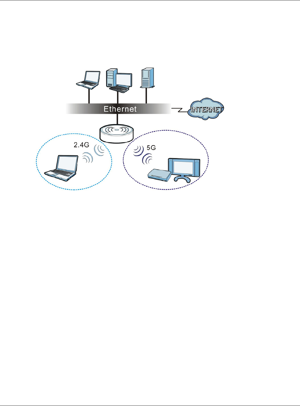
1.1.1 Dual-Band
The EMG3425-Q10A is a dual-band AP and able to function both 2.4G and 5G networks at the same
time. You could use the 2.4 GHz band for regular Internet surfing and downloading while using the
5 GHz band for time sensitive traffic like high-definition video, music, and gaming.
Figure 1 Dual-Band Application
1.2 Applications
You can have the following networks with the EMG3425-Q10A:
•W ir e d. You can connect network devices via the Ethernet ports of the EMG3425-Q10A so that
they can communicate with each other and access the Internet.
•W ire less. Wireless clients can connect to the EMG3425-Q10A to access network resources. You
can use WPS (Wi-Fi Protected Setup) to create an instant network connection with another WPS-
compatible device.
•W AN . Connect to a broadband modem/router for Internet access.
1.3 Ways to Manage the EMG3425-Q10A
Use any of the following methods to manage the EMG3425-Q10A.
• WPS (Wi-Fi Protected Setup). You can use the WPS button or the WPS section of the Web
Configurator to set up a wireless network with your EMG3425-Q10A.
• Web Configurator. This is recommended for everyday management of the EMG3425-Q10A using
a (supported) web browser.

Chapter 1 Introduction
EMG3425-Q10A User’s Guide
14
1.4 Good Habits for Managing the EMG3425-Q10A
Do the following things regularly to make the EMG3425-Q10A more secure and to manage the
EMG3425-Q10A more effectively.
• Change the password. Use a password that’s not easy to guess and that consists of different
types of characters, such as numbers and letters.
• Write down the password and put it in a safe place.
• Back up the configuration (and make sure you know how to restore it). Restoring an earlier
working configuration may be useful if the device becomes unstable or even crashes. If you
forget your password, you will have to reset the EMG3425-Q10A to its factory default settings. If
you backed up an earlier configuration file, you would not have to totally re-configure the
EMG3425-Q10A. You could simply restore your last configuration.
1.5 Resetting the EMG3425-Q10A
If you forget your password or IP address, or you cannot access the Web Configurator, you will need
to use the RESET button at the back of the EMG3425-Q10A to reload the factory-default
configuration file. This means that you will lose all configurations that you had previously saved, the
user name will be reset to “supervisor” or “admin”, the password will be reset to “supervisor” or
“1234”, and the IP address will be reset to “192.168.1.1” (router mode).
1.5.1 How to Use the RESET Button
1Make sure the power LED is on.
2Press the RESET button for one to four seconds to restart/reboot the EMG3425-Q10A.
3Press the RESET button for longer than five seconds to set the EMG3425-Q10A back to its factory-
default configurations.
1.6 The WPS Button
Your EMG3425-Q10A supports Wi-Fi Protected Setup (WPS), which is an easy way to set up a
secure wireless network. WPS is an industry standard specification, defined by the Wi-Fi Alliance.
WPS allows you to quickly set up a wireless network with strong security, without having to
configure security settings manually. Each WPS connection works between two devices. Both
devices must support WPS (check each device’s documentation to make sure).
Depending on the devices you have, you can either press a button (on the device itself, or in its
configuration utility) or enter a PIN (a unique Personal Identification Number that allows one device
to authenticate the other) on each of the two devices. When WPS is activated on a device, it has
two minutes to find another device that also has WPS activated. Then, the two devices connect and
set up a secure network by themselves.
Chapter 1 Introduction
EMG3425-Q10A User’s Guide
15
You can use the WPS button ( ) on the front panel of the EMG3425-Q10A to activate WPS in
order to quickly set up a wireless network with strong security.
1Make sure the power LED is on (not blinking).
2Press the WPS button for more than three seconds and release it. Press the WPS button on another
WPS-enabled device within range of the EMG3425-Q10A.
Note: You must activate WPS on the EMG3425-Q10A and on another wireless device
within two minutes of each other.
For more information on using WPS, see Section 6.2 on page 38.
1.7 LEDs
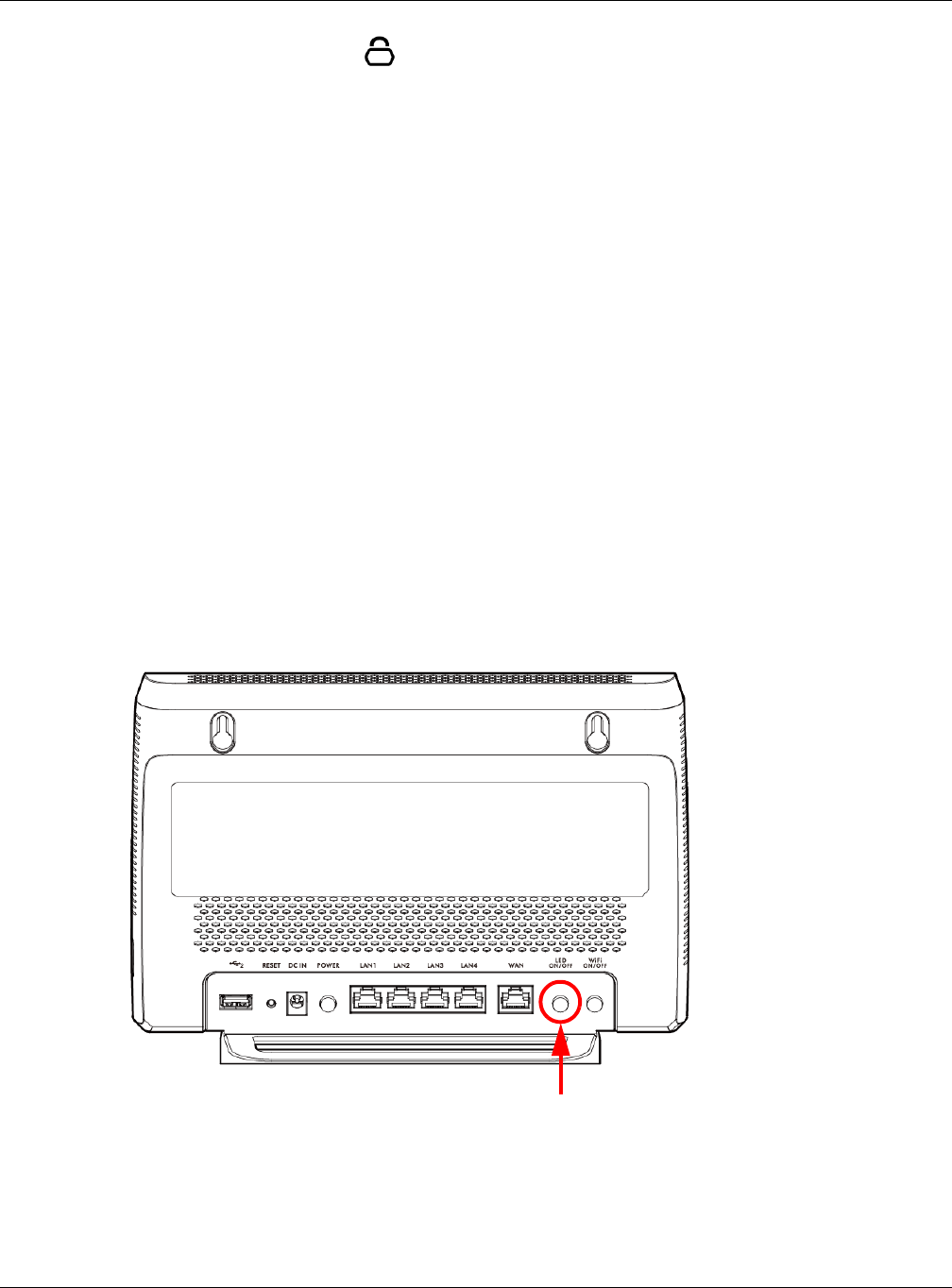
Look at the LED lights on the front panel to determine the status of the EMG3425-Q10A. Use the
LED button on the rear panel of the device to turn the LED lights on or off. If you have already
pushed the LED button to the ON position but none of the LEDS are on, make sure the EMG3425-
Q10A is receiving power and the power is turned on.
Note: The Pow e r LED will be on even if you push the LED button to the OFF position.
This is for you to determine whether the EMG3425-Q10A is powered on.
Figure 2 LED Button
LED button
Chapter 1 Introduction
EMG3425-Q10A User’s Guide
16
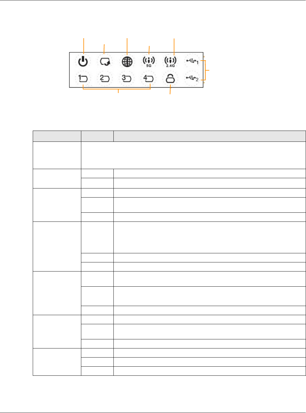
Figure 3 Front Panel
The following table describes the LEDs and the WPS button.
Table 1 Front panel LEDs and WPS button
LED STATUS DESCRIPTION
WPS Button Press this button for 1 second to set up a wireless connection via WiFi Protected Setup
with another WPS-enabled client. You must press the WPS button on the client side within
120 seconds for a successful connection. See Section 1.6 on page 14 and Section 6.2 on
page 38 for more information on WPS.
Power On The EMG3425-Q10A is receiving power and functioning properly.
Off The EMG3425-Q10A is not receiving power.
WAN On The EMG3425-Q10A’s WAN connection is ready.
Blinking The EMG3425-Q10A is sending/receiving data through the WAN with a
1000Mbps transmission rate.
Off The WAN connection is not ready, or has failed.
Internet On The EMG3425-Q10A has an IP connection but no traffic.
Your device has a WAN IP address (either static or assigned by a DHCP
server), PPP negotiation was successfully completed (if used) and the
connection is up.
Blinking The EMG3425-Q10A is sending or receiving IP traffic.
Off The EMG3425-Q10A does not have an IP connection.
WLAN 2.4/5G On The EMG3425-Q10A is ready, but is not sending/receiving data through the
5G wireless LAN.
Blinking The EMG3425-Q10A is sending/receiving data through the 5G wireless LAN.
The EMG3425-Q10A is negotiating a WPS connection with a wireless client.
Off The wireless LAN is not ready or has failed.
LAN 1-4 On The EMG3425-Q10A’s LAN connection is ready.
Blinking The EMG3425-Q10A is sending/receiving data through the LAN with a
1000Mbps transmission rate.
Off The LAN connection is not ready, or has failed.
WPS On WPS is enabled.
Blinking The EMG3425-Q10A is negotiating a WPS connection with a wireless client.
Off WPS is disabled.
Pow e r
LAN 1 -4
WAN
WPS
USB 1 -2
Int e rnet
WLAN 5 G
WLAN 2 .4G

Chapter 1 Introduction
EMG3425-Q10A User’s Guide
17
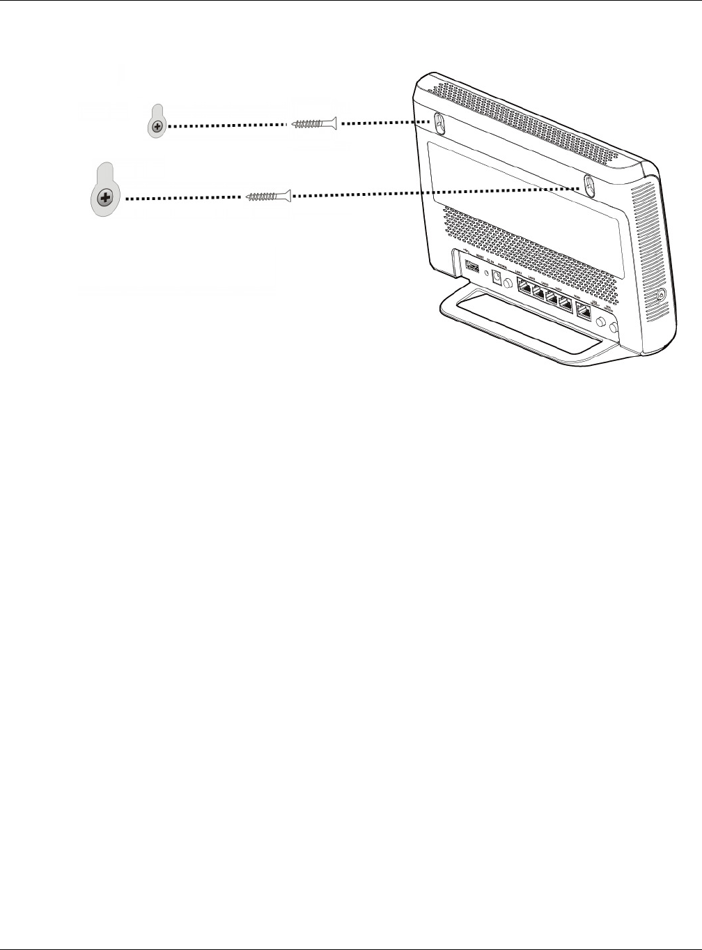
1.8 Wall Mounting
You may need screw anchors if mounting on a concrete or brick wall.
1Select a position free of obstructions on a wall strong enough to hold the weight of the device.
2Mark two holes on the wall at the appropriate distance apart for the screws.
Be careful to avoid damaging pipes or cables located inside the wall
when drilling holes for the screws.
3If using screw anchors, drill two holes for the screw anchors into the wall. Push the anchors into the
full depth of the holes, then insert the screws into the anchors. Do not insert the screws all the way
in - leave a small gap of about 0.5 cm.
If not using screw anchors, use a screwdriver to insert the screws into the wall. Do not insert the
screws all the way in - leave a gap of about 0.5 cm.
4Make sure the screws are fastened well enough to hold the weight of the EMG3425-Q10A with the
connection cables.
5Align the holes on the back of the EMG3425-Q10A with the screws on the wall. Hang the EMG3425-
Q10A on the screws.
USB 1-2 On The EMG3425-Q10A has a USB device installed.
Blinking The EMG3425-Q10A is transmitting and/or receiving data from routers
through an installed USB device.
Off There is no USB device connected to the EMG3425-Q10A.
Table 1 Front panel LEDs and WPS button (continued)
LED STATUS DESCRIPTION
Table 2 Wall Mounting Information
Distance between holes 12.7 cm
M4 Screws Two
Screw anchors (optional) Two
Chapter 1 Introduction
EMG3425-Q10A User’s Guide
18
Figure 4 Wall Mounting Example

EMG3425-Q10A User’s Guide
19
CHAPTER 2
Introducing the Web Configurator
2.1 Overview
This chapter describes how to access the EMG3425-Q10A Web Configurator and provides an
overview of its screens.
The Web Configurator is an HTML-based management interface that allows easy setup and
management of the EMG3425-Q10A via Internet browser. Use Internet Explorer 9.0 and later
versions, Mozilla Firefox 21 and later versions, Safari 6.0 and later versions or Google Chrome 26.0
and later versions. The recommended screen resolution is 1024 by 768 pixels.
In order to use the Web Configurator you need to allow:
• Web browser pop-up windows from your device. Web pop-up blocking is enabled by default in
Windows XP SP (Service Pack) 2.
• JavaScript (enabled by default).
• Java permissions (enabled by default).
Refer to the Troubleshooting chapter (Chapter 26 on page 187) to see how to make sure these
functions are allowed in Internet Explorer.
2.2 Login Accounts
There are two system accounts that you can use to log in to the EMG3425-Q10A: “adm in” and
“supe r visor ”. These two accounts have different privilege levels. The web configurator screens
vary depending on which account you use to log in.
The supe r visor accounts allows you full access to all system configurations. The default supervisor
user name is “supervisor” and password is “supervisor”.
With the adm in account, you cannot access Re m ot e MGM T screens and can only view the Sys OP
Mode screen. The default username is “admin” and password is “1234”.
2.3 Accessing the Web Configurator
1Make sure your EMG3425-Q10A hardware is properly connected and prepare your computer or
computer network to connect to the EMG3425-Q10A (refer to the Quick Start Guide).
2Launch your web browser.
Chapter 2 Introducing the Web Configurator
EMG3425-Q10A User’s Guide
20
3The EMG3425-Q10A is in router mode by default. Type "http://192.168.1.1" as the website
address.
If the EMG3425-Q10A is in access point, the IP address is 192.168.1.2. See Chapter 3 on page 23
for more information about the modes of the EMG3425-Q10A.
Your computer must be in the same subnet in order to access this website address.
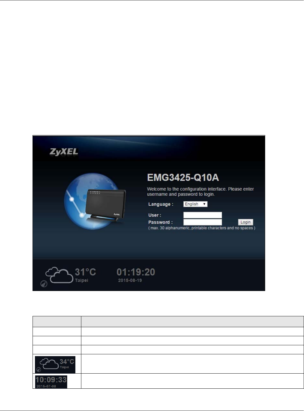
2.3.1 Login Screen
The Web Configurator initially displays the following login screen.
If you are logging in with the “a dm in” account, type “1234” (default) as the password.
If you are logging in with the “su pe r visor ” account, type “supervisor” (default) as the password.
Then click Login.
Figure 5 Login screen
The following table describes the labels in this screen.
Table 3 Login screen
LABEL DESCRIPTION
Language Select the language you want to use to configure the Web Configurator.
User Type “supervisor” or "admin" (default) as the user name.
Password Type “supervisor” or "1234" (default) as the password. Click Login.
This shows the current weather, either in celsius or fahrenheit, of the city you specify in
Section 2.3.2.1 on page 21.
This shows the time (hh:mm:ss) and date (yyyy:mm:dd) of the timezone you select in
Section 25.5 on page 178. The time is in 24-hour format, for example 15:00 is 3:00 PM.
Chapter 2 Introducing the Web Configurator
EMG3425-Q10A User’s Guide
21
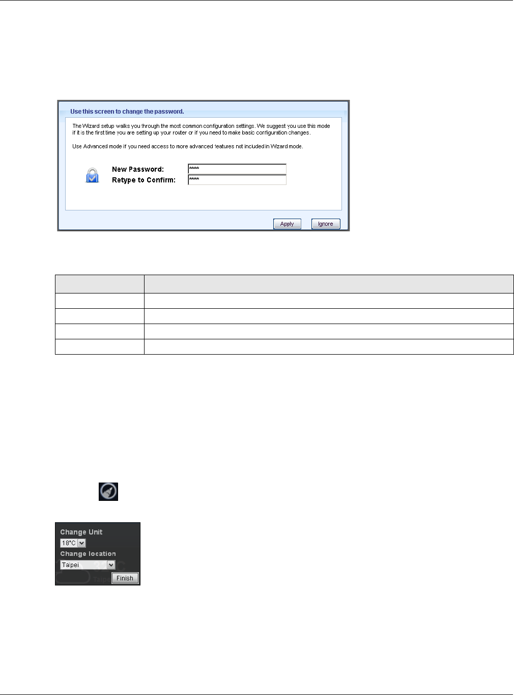
2.3.2 Password Screen
You should see a screen asking you to change your password (highly recommended) as shown
next.
Figure 6 Change Password Screen
The following table describes the labels in this screen.
Note: The management session automatically times out when the time period set in the
Adm inist rat or I nact ivit y Tim er field expires (default five minutes; go to Chapter
25 on page 176 to change this). Simply log back into the EMG3425-Q10A if this
happens.
2.3.2.1 Weather Edit
You can change the temperature unit and select the location for which you want to know the
weather.
Click the icon to change the Weather display.
Figure 7 Change Weather
Table 4 Change Password Screen
LABEL DESCRIPTION
New Password Type a new password.
Retype to Confirm Retype the password for confirmation.
Apply Click Apply to save your changes back to the EMG3425-Q10A.
Ignore Click I gnore if you do not want to change the password this time.

Chapter 2 Introducing the Web Configurator
EMG3425-Q10A User’s Guide
22
The following table describes the labels in this screen.
Table 5 Change Weather
LABEL DESCRIPTION
Change Unit Choose which temperature unit you want the EMG3425-Q10A to display.
Change Location Select the location for which you want to know the weather. If the city you want is not
listed, choose one that is closest to it.
Finish Click this to apply the settings and refresh the date and time display.

EMG3425-Q10A User’s Guide
23
CHAPTER 3
EMG3425-Q10A Modes
3.1 Overview
This chapter introduces the operating mode of your EMG3425-Q10A, or simply how the EMG3425-
Q10A is being used in the network.
3.1.1 Device Modes
This refers to the operating mode of the EMG3425-Q10A, which can act as a:
•Rout er : This is the default device mode of the EMG3425-Q10A. Use this mode to connect the
local network to another network, like the Internet. Go to Section 4.2 on page 24 to view the
St a t us screen in this mode.
•Acce ss Point : Use this mode if you want to extend your network by allowing network devices to
connect to the EMG3425-Q10A wirelessly. Go to Section 5.4 on page 33 to view the St a t us
screen in this mode.
For more information on these modes and to change the mode of your EMG3425-Q10A, refer to
Chapter 25 on page 184.
Note: Choose your device mode carefully to avoid having to change it later.
When changing to another mode, the IP address of the EMG3425-Q10A changes. The running
applications and services of the network devices connected to the EMG3425-Q10A can be
interrupted.
EMG3425-Q10A User’s Guide
24
CHAPTER 4
Router Mode
4.1 Overview
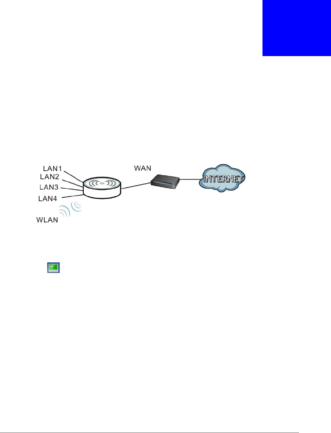
The EMG3425-Q10A is set to router mode by default. Routers are used to connect the local network
to another network (for example, the Internet). In the figure below, the EMG3425-Q10A connects
the local network (LAN 1 ~ LAN 4 ) to the Internet.
Figure 8 EMG3425-Q10A Network
4.2 Router Mode Status Screen
Click to open the status screen.
Modem
Chapter 4 Router Mode
EMG3425-Q10A User’s Guide
25
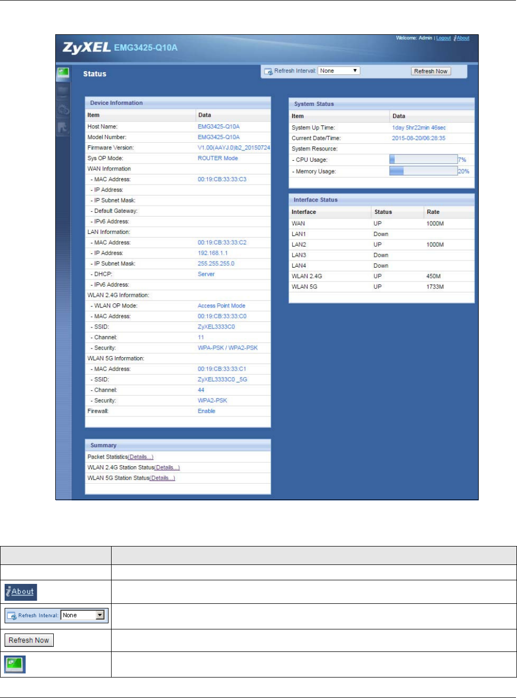
Figure 9 Status Screen: Router Mode
The following table describes the icons shown in the St a t us screen.
Table 6 Status Screen Icon Key
ICON DESCRIPTION
Logout Click this at any time to exit the Web Configurator.
Click this icon to view copyright and a link for related product information.
Select a number of seconds or N on e from the drop-down list box to refresh all screen statistics
automatically at the end of every time interval or to not refresh the screen statistics.
Click this button to refresh the status screen statistics.
Click this icon to see the St a t us page. The information in this screen depends on the device
mode you select.

Chapter 4 Router Mode
EMG3425-Q10A User’s Guide
26
The following table describes the labels shown in the St a t us screen.
Click this icon to see the M onitor navigation menu.
Click this icon to see the Conf igu r a t ion navigation menu.
Click this icon to see the M a in t e na n ce navigation menu.
Table 6 Status Screen Icon Key (continued)
ICON DESCRIPTION
Table 7 Status Screen: Router Mode
LABEL DESCRIPTION
Device Information
Host Name This is the Syst em N a m e you enter in the M a int e n a nce > Ge neral screen. It is for
identification purposes.
Model Number This is the model name of your device.
Firmware Version This is the firmware version and the date created.
Sys OP Mode This is the device mode (Section 3.1.1 on page 23) to which the EMG3425-Q10A is set -
Rou t e r M ode .
WAN Information
MAC Address This shows the WAN Ethernet adapter MAC Address of your device.
IP Address This shows the WAN port’s IP address.
IP Subnet Mask This shows the WAN port’s subnet mask.
Default Gateway This shows the WAN port’s gateway IP address.
IPv6 Address This shows the IPv6 address of the EMG3425-Q10A on the WAN.
LAN Information
MAC Address This shows the LAN Ethernet adapter MAC Address of your device.
IP Address This shows the LAN port’s IP address.
IP Subnet Mask This shows the LAN port’s subnet mask.
DHCP This shows the LAN port’s DHCP role - Serve r or D isable.
IPv6 Address This shows the IPv6 address of the EMG3425-Q10A on the LAN.
WLAN 2.4G Information
WLAN OP Mode This is the device mode (Section 3.1.1 on page 23) to which the EMG3425-Q10A’s wireless
LAN is set - Acce ss Poin t M ode .
MAC Address This shows the 2.4GHz wireless adapter MAC Address of your device.
SSID This shows a descriptive name used to identify the EMG3425-Q10A in the 2.4GHz wireless
LAN.
Channel This shows the channel number which you select manually.
Security This shows the level of wireless security the EMG3425-Q10A is using.
WLAN 5G Information
MAC Address This shows the 5GHz wireless adapter MAC Address of your device.
SSID This shows a descriptive name used to identify the EMG3425-Q10A in the 5GHz wireless
LAN.
Channel This shows the channel number which you select manually.
Security This shows the level of wireless security the EMG3425-Q10A is using.
Firewall This shows whether the firewall is enabled or not.

Chapter 4 Router Mode
EMG3425-Q10A User’s Guide
27
4.2.1 Navigation Panel
Use the sub-menus on the navigation panel to configure EMG3425-Q10A features.
Summary
Packet Statistics Click De t a ils.. . to go to the Monitor > Pack et St a t istics screen (Section 7.5 on page 53).
Use this screen to view port status and packet specific statistics.
WLAN 2.4G Station
Status Click D e t a ils... to go to the M on it or > W LAN 2 .4 G Station St atus screen (Section 7.6 on
page 54). Use this screen to view the wireless stations that are currently associated to the
EMG3425-Q10A’s 2.4GHz wireless LAN.
WLAN 5G Station Status Click D et ai ls. .. to go to the M onit or > W LAN 5 G St a t ion St atus screen (Section 7.6 on
page 54). Use this screen to view the wireless stations that are currently associated to the
EMG3425-Q10A’s 5GHz wireless LAN.
System Status
Item This column shows the type of data the EMG3425-Q10A is recording.
Data This column shows the actual data recorded by the EMG3425-Q10A.
System Up Time This is the total time the EMG3425-Q10A has been on.
Current Date/Time This field displays your EMG3425-Q10A’s present date and time.
System Resource
- CPU Usage This displays what percentage of the EMG3425-Q10A’s processing ability is currently used.
When this percentage is close to 100%, the EMG3425-Q10A is running at full load, and the
throughput is not going to improve anymore. If you want some applications to have more
throughput, you should turn off other applications (for example, using bandwidth
management.)
- Memory Usage This shows what percentage of the heap memory the EMG3425-Q10A is using.
Interface Status
Interface This displays the EMG3425-Q10A port types. The port types are: W AN , LAN and W LAN .
Status For the LAN and WAN ports, this field displays Dow n (line is down) or Up (line is up or
connected).
For the 2.4GHz/5GHz WLAN, it displays Up when the 2.4GHz/5GHz WLAN is enabled or
Dow n when the 2.4G/5G WLAN is disabled.
Rate For the LAN ports, this displays the port speed and duplex setting or N / A when the line is
disconnected.
For the WAN port, it displays the port speed and duplex setting if you’re using Ethernet
encapsulation. This field displays N / A when the line is disconnected.
For the 2.4GHz/5GHz WLAN, it displays the maximum transmission rate when the 2.4GHz/
5GHz WLAN is enabled and N / A when the WLAN is disabled.
Table 7 Status Screen: Router Mode (continued)
LABEL DESCRIPTION
Chapter 4 Router Mode
EMG3425-Q10A User’s Guide
28
Figure 10 Navigation Panel: Router Mode
The following table describes the sub-menus.
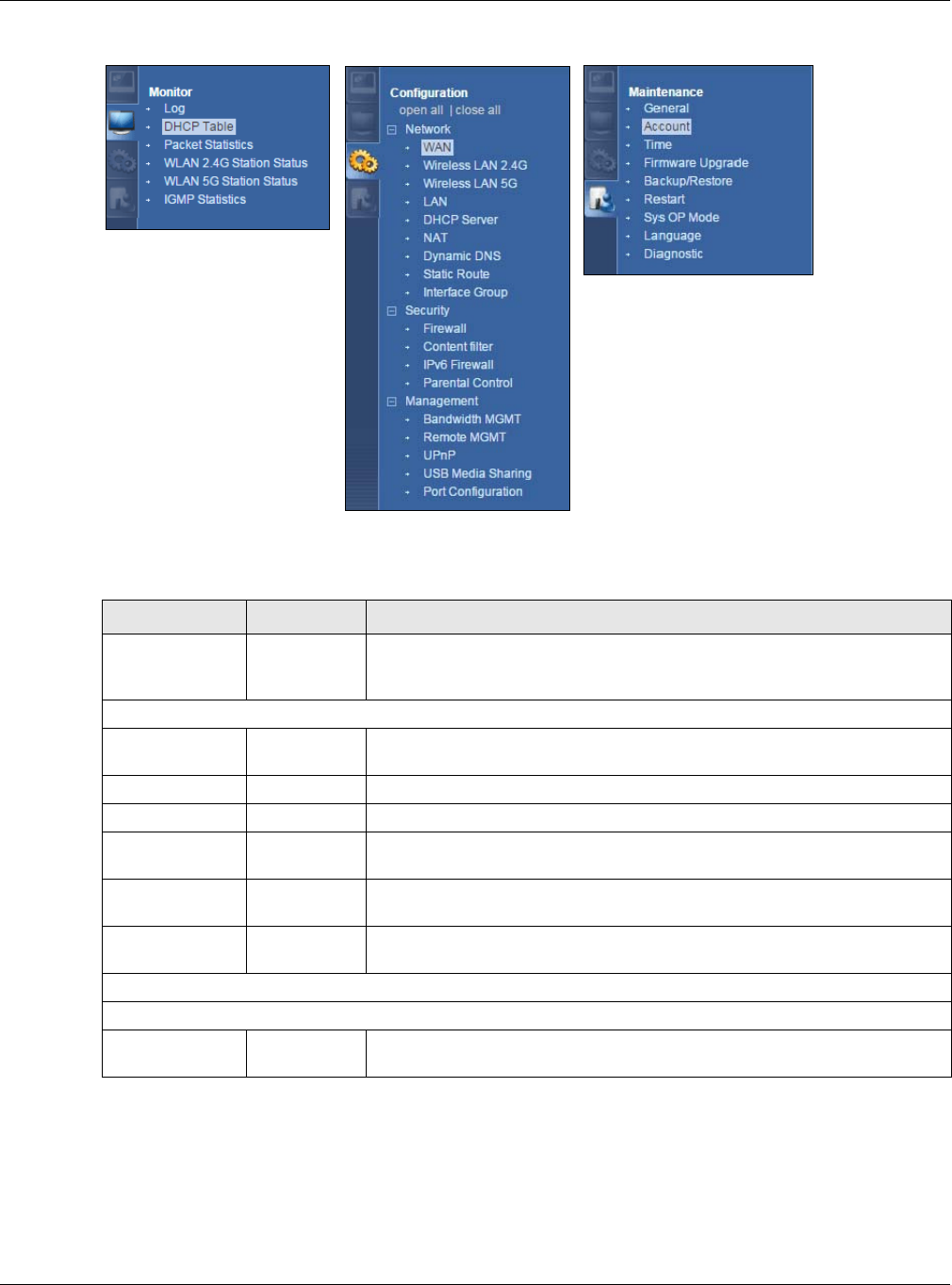
Table 8 Navigation Panel: Router Mode
LINK TAB FUNCTION
Status This screen shows the EMG3425-Q10A’s general device, system and
interface status information. Use this screen to access the wizard, and
summary statistics tables.
M ON I TOR
Log Use this screen to view the list of activities recorded by your EMG3425-
Q10A.
DHCP Table Use this screen to view current DHCP client information.
Packet Statistics Use this screen to view port status and packet specific statistics.
WLAN 2.4G
Station Status
Use this screen to view the wireless stations that are currently associated
to the EMG3425-Q10A’s 2.4GHz wireless LAN.
WLAN 5G
Station Status
Use this screen to view the wireless stations that are currently associated
to the EMG3425-Q10A’s 5GHz wireless LAN.
IGMP Statistics Use this screen to view the EMG3425-Q10A’s IGMP multicast group and
IGMP traffic statistics.
CON FI GURATI ON
Network
WAN Management
WAN
This screen allows you to configure ISP parameters, WAN IP address
assignment, DNS servers, the WAN MAC address, and VLAN settings.

Chapter 4 Router Mode
EMG3425-Q10A User’s Guide
29
Wireless LAN
2.4G/5G General Use this screen to enable the wireless LAN and configure wireless LAN and
wireless security settings.
More AP Use this screen to configure multiple BSSs on the EMG3425-Q10A.
MAC Filter Use the MAC filter screen to configure the EMG3425-Q10A to block access
to devices or block the devices from accessing the EMG3425-Q10A.
Advanced This screen allows you to configure advanced wireless settings.
QoS Use this screen to configure Wi-Fi Multimedia Quality of Service (WMM
QoS). WMM QoS allows you to prioritize wireless traffic according to the
delivery requirements of individual services.
WPS Use this screen to configure WPS.
WPS Station Use this screen to add a wireless station using WPS.
Scheduling Use this screen to schedule the times the Wireless LAN is enabled.
LAN IP Use this screen to configure LAN IP address and subnet mask.
IP Alias Use this screen to have the EMG3425-Q10A apply IP alias to create LAN
subnets.
IPv6 LAN Use this screen to configure the IPv6 address for the EMG3425-Q10A on
the LAN.
IGMP
Snooping
Use this screen to activate IGMP snooping and configure IGMP modes.
DHCP Server General Use this screen to enable the EMG3425-Q10A’s DHCP server.
Advanced Use this screen to assign IP addresses to specific individual computers
based on their MAC addresses and to have DNS servers assigned by the
DHCP server.
Client List Use this screen to view information related to your DHCP status.
NAT General Use this screen to enable NAT.
Port
Forwarding
Use this screen to configure servers behind the EMG3425-Q10A and
forward incoming service requests to the server(s) on your local network.
Port Trigger Use this screen to change your EMG3425-Q10A’s port triggering settings.
Dynamic
DNS Dynamic DNS Use this screen to set up dynamic DNS.
Static Route Static Route Use this screen to configure IP static routes.
Interface
Group Interface
Group
Use this screen to add a LAN interface or a VLAN ID to a new group.
Security
Firewall General Use this screen to activate/deactivate the firewall.
Services This screen shows a summary of the firewall rules, and allows you to edit/
add a firewall rule.
Content
Filter Content Filter Use this screen to restrict web features and designate a trusted computer.
IPv6 firewall Services Use this screen to configure IPv6 firewall rules.
Parental
Control Use this screen to block certain web features and sites containing certain
keywords in the URL.
Management
Bandwidth
MGMT General Use this screen to enable or disable QoS and set the upstream bandwidth.
Queue Setup Use this screen to configure QoS queue assignment.
Class Setup Use this screen to configure QoS classifiers.
Table 8 Navigation Panel: Router Mode (continued)
LINK TAB FUNCTION

Chapter 4 Router Mode
EMG3425-Q10A User’s Guide
30
Remote
MGMT WWW Use this screen to configure through which interface(s) and from which IP
address(es) users can use HTTP or HTTPS to manage the EMG3425-Q10A.
Telnet Use this screen to configure through which interface(s) and from which IP
address(es) users can use Telnet to manage the EMG3425-Q10A.
SNMP Use this screen to to configure your EMG3425-Q10A's settings for Simple
Network Management Protocol management.
Wake On LAN Use this screen to enable Wake on LAN to remotely turn on a device on the
local network.
TR069 Use this screen to configure the EMG3425-Q10A to be managed by an ACS
(Auto Configuration Server).
UPnP UPnP Use this screen to enable UPnP on the EMG3425-Q10A.
USB Media
Sharing DLNA Use this screen to have the EMG3425-Q10A function as a DLNA-compliant
media server, that lets DLNA-compliant media clients play video, audio, and
photo content files stored on the connected USB storage device.
SAMBA Use this screen to enable file sharing through the EMG3425-Q10A.
FTP Use this screen to have the EMG3425-Q10A act as a FTP server.
Port
Configuration Port
Configuration
Use this screen to change the Ethernet port speed and duplex settings.
M AI N TEN AN CE
General General Use this screen to view and change administrative settings such as system
and domain names.
Account User Account Use this screen to change the password of your EMG3425-Q10A.
Time Time Setting Use this screen to change your EMG3425-Q10A’s time and date.
Firmware
Upgrade Firmware
Upgrade
Use this screen to upload firmware to your EMG3425-Q10A.
Backup/
Restore Backup/
Restore
Use this screen to backup and restore the configuration or reset the factory
defaults to your EMG3425-Q10A.
Restart System
Restart
This screen allows you to reboot the EMG3425-Q10A without turning the
power off.
Sys OP Mode Sys OP Mode This screen allows you to select whether your device acts as a router, or an
access point.
Language Language This screen allows you to select the language you prefer.
Diagnostic Ping Use this screen to ping an IP address.
Table 8 Navigation Panel: Router Mode (continued)
LINK TAB FUNCTION
EMG3425-Q10A User’s Guide
31
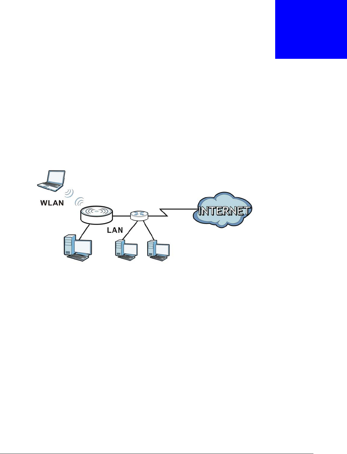
CHAPTER 5
Access Point Mode
5.1 Overview
Use your EMG3425-Q10A as an access point (AP) if you already have a router or gateway on your
network. In this mode your EMG3425-Q10A bridges a wired network (LAN) and wireless LAN
(WLAN) in the same subnet. See the figure below for an example.
Figure 11 Wireless Internet Access in Access Point Mode
Many screens that are available in Rou t er Mode are not available in Access Poin t M ode, such as
bandwidth management and firewall.
5.2 What You Can Do
•Use the St a t us screen to view read-only information about your EMG3425-Q10A (Section 5.4 on
page 33).
•Use the LAN screen to set the IP address for your EMG3425-Q10A acting as an access point
(Section 5.5 on page 35).
5.3 What You Need to Know
See Chapter 6 on page 38 for a tutorial on setting up a network with the EMG3425-Q10A as an
access point.
Chapter 5 Access Point Mode
EMG3425-Q10A User’s Guide
32
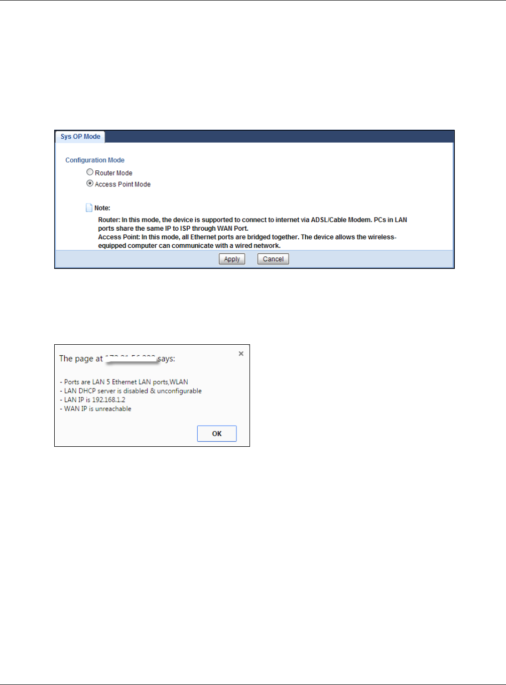
5.3.1 Setting your EMG3425-Q10A to AP Mode
1Log into the Web Configurator if you haven’t already. See the Quick start Guide for instructions on
how to do this.
2To use your EMG3425-Q10A as an access point, go to Ma intena n ce > Sys OP Mode and select
Acce ss Poin t M ode .
Figure 12 Changing to Access Point mode
Note: You have to log in to the Web Configurator again when you change modes. As soon
as you do, your EMG3425-Q10A is already in Access Point mode.
3When you select Access Point Mode , the following pop-up message window appears.
Figure 13 Pop up for Access Point mode
Click OK. Then click Apply. The Web Configurator refreshes once the change to Access Point mode
is successful.
5.3.2 Accessing the Web Configurator in Access Point Mode
Log in to the Web Configurator in Access Point mode, do the following:
1Connect your computer to the LAN port of the EMG3425-Q10A.
2The default IP address of the EMG3425-Q10A is “192.168.1.2”. In this case, your computer must
have an IP address in the range between “192.168.1.3” and “192.168.1.254”.
3Click St art > Run on your computer in Windows. Type “cmd” in the dialog box. Enter “ipconfig” to
show your computer’s IP address. If your computer’s IP address is not in the correct range then see
Appendix B on page 203 for information on changing your computer’s IP address.
Chapter 5 Access Point Mode
EMG3425-Q10A User’s Guide
33
4After you’ve set your computer’s IP address, open a web browser such as Internet Explorer and
type “192.168.1.2” as the web address in your web browser.
5.3.3 Configuring your WLAN and Maintenance Settings
The configuration of wireless and maintenance settings in Access Point M ode is the same as for
Router Mode.
•See
Chapter 9 on page 68 for information on the configuring your wireless network.
•See
Chapter 25 on page 176 for information on configuring your Maintenance settings.
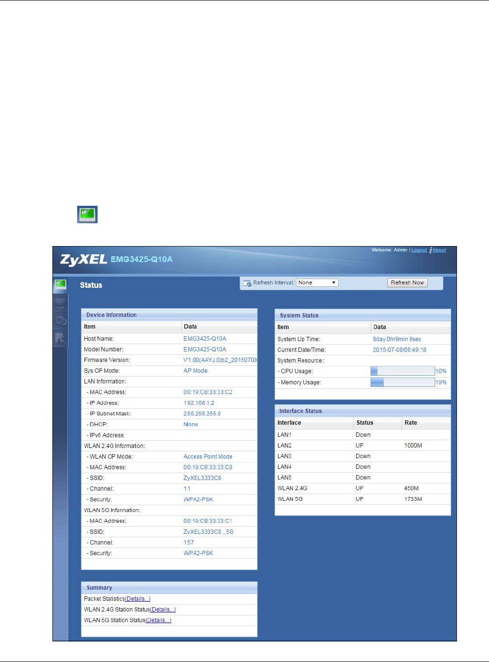
5.4 AP Mode Status Screen
Click to open the St a t u s screen.
Figure 14 Status Screen: Access Point Mode

Chapter 5 Access Point Mode
EMG3425-Q10A User’s Guide
34
The following table describes the labels shown in the St a t us screen.
Table 9 Status Screen: Access Point Mode
LABEL DESCRIPTION
Device Information
Host Name This is the Syst em N a m e you enter in the M a int e n a nce > Ge neral screen. It is for
identification purposes.
Model Number This is the model name of your device.
Firmware Version This is the firmware version and the date created.
Sys OP Mode This is the device mode (Section 3.1.1 on page 23) to which the EMG3425-Q10A is set - AP
Mode.
LAN Information
MAC Address This shows the LAN Ethernet adapter MAC Address of your device.
IP Address This shows the LAN port’s IP address.
IP Subnet Mask This shows the LAN port’s subnet mask.
DHCP This shows the LAN port’s DHCP role - Clie n t or N on e.
IPv6 Address This shows the IPv6 address of the EMG3425-Q10A on the LAN.
WLAN 2.4G Information
WLAN OP Mode This is the device mode (Section 3.1.1 on page 23) to which the EMG3425-Q10A’s wireless
LAN is set - Acce ss Poin t M ode .
MAC Address This shows the 2.4GHz wireless adapter MAC Address of your device.
SSID This shows a descriptive name used to identify the EMG3425-Q10A in the 2.4GHz wireless
LAN.
Channel This shows the channel number which you select manually.
Security This shows the level of wireless security the EMG3425-Q10A is using.
WLAN 5G Information
MAC Address This shows the 5GHz wireless adapter MAC Address of your device.
SSID This shows a descriptive name used to identify the EMG3425-Q10A in the 5GHz wireless
LAN.
Channel This shows the channel number which you select manually.
Security This shows the level of wireless security the EMG3425-Q10A is using.
Summary
Packet Statistics Click De t a ils.. . to go to the Monitor > Pack et St a t istics screen (Section 7.5 on page 53).
Use this screen to view port status and packet specific statistics.
WLAN 2.4G Station
Status Click D e t a ils... to go to the M on it or > W LAN 2 .4 G Station St atus screen (Section 7.6 on
page 54). Use this screen to view the wireless stations that are currently associated to the
EMG3425-Q10A’s 2.4GHz wireless LAN.
WLAN 5G Station Status Click D et ai ls. .. to go to the M onit or > W LAN 5 G St a t ion St atus screen (Section 7.6 on
page 54). Use this screen to view the wireless stations that are currently associated to the
EMG3425-Q10A’s 5GHz wireless LAN.
System Status
Item This column shows the type of data the EMG3425-Q10A is recording.
Data This column shows the actual data recorded by the EMG3425-Q10A.
System Up Time This is the total time the EMG3425-Q10A has been on.
Current Date/Time This field displays your EMG3425-Q10A’s present date and time.
System Resource
Chapter 5 Access Point Mode
EMG3425-Q10A User’s Guide
35
5.4.1 Navigation Panel
Use the menu in the navigation panel to configure EMG3425-Q10A features in Acce ss Point Mode.
Figure 15 Menu: Access Point Mode
Refer to Table 8 on page 28 for descriptions of the labels shown in the navigation panel.
5.5 LAN Screen
Use this section to configure your LAN settings while in Access Point Mode.
Click N et w ork > LAN to see the screen below.
Note: If you change the IP address of the EMG3425-Q10A in the screen below, you will
need to log into the EMG3425-Q10A again using the new IP address.
- CPU Usage This displays what percentage of the EMG3425-Q10A’s processing ability is currently used.
When this percentage is close to 100%, the EMG3425-Q10A is running at full load, and the
throughput is not going to improve anymore. If you want some applications to have more
throughput, you should turn off other applications (for example, using bandwidth
management.)
- Memory Usage This shows what percentage of the heap memory the EMG3425-Q10A is using.
Interface Status
Interface This displays the EMG3425-Q10A port types. The port types are: LAN and W LAN .
Status For the LAN ports, this field displays Dow n (line is down) or Up (line is up or connected).
For the 2.4GHz/5GHz WLAN, it displays Up when the 2.4GHz/5GHz WLAN is enabled or
Dow n when the 2.4G/5G WLAN is disabled.
Rate For the LAN ports, this displays the port speed and duplex setting or N / A when the line is
disconnected.
For the 2.4GHz/5GHz WLAN, it displays the maximum transmission rate when the 2.4GHz/
5GHz WLAN is enabled and N / A when the WLAN is disabled.
Table 9 Status Screen: Access Point Mode (continued)
LABEL DESCRIPTION
Chapter 5 Access Point Mode
EMG3425-Q10A User’s Guide
36
Figure 16 Network > LAN > IP
The table below describes the labels in the screen.
Table 10 Network > LAN > IP
LABEL DESCRIPTION
Obtain an IP Address
Automatically
When you enable this, the EMG3425-Q10A gets its IP address from the network’s
DHCP server (for example, your ISP). Users connected to the EMG3425-Q10A can
now access the network (i.e., the Internet if the IP address is given by the ISP).
The Web Configurator may no longer be accessible unless you know the IP address
assigned by the DHCP server to the EMG3425-Q10A. You need to reset the
EMG3425-Q10A to be able to access the Web Configurator again (see Section 25.7
on page 181 for details on how to reset the EMG3425-Q10A).
Also when you select this, you cannot enter an IP address for your EMG3425-Q10A
in the field below.
Static IP Address Click this if you want to specify the IP address of your EMG3425-Q10A. Or if your
ISP or network administrator gave you a static IP address to access the network or
the Internet.
IP Address Type the IP address in dotted decimal notation. The default setting is 192.168.1.2.
If you change the IP address you will have to log in again with the new IP address.
Subnet Mask The subnet mask specifies the network number portion of an IP address. Your
EMG3425-Q10A will automatically calculate the subnet mask based on the IP
address that you assign. Unless you are implementing subnetting, use the subnet
mask computed by the EMG3425-Q10A.
Gateway IP Address Enter a Gatew a y I P Address (if your ISP or network administrator gave you one)
in this field.
DNS Server
First DNS Server
Second DNS Server
Third DNS Server
Select Obt a in ed Fr om I SP if your ISP dynamically assigns DNS server information
(and the EMG3425-Q10A's WAN IP address). The field to the right displays the
(read-only) DNS server IP address that the ISP assigns.
Select Use r- D efined if you have the IP address of a DNS server. Enter the DNS
server's IP address in the field to the right. If you chose User- De fin ed, but leave
the IP address set to 0.0.0.0, User- Defined changes to N on e after you click
Apply. If you set a second choice to Use r- Defin ed, and enter the same IP
address, the second Use r- D efine d changes to N on e after you click Apply.
Select N on e if you do not want to configure DNS servers. If you do not configure a
DNS server, you must know the IP address of a computer in order to access it.

Chapter 5 Access Point Mode
EMG3425-Q10A User’s Guide
37
Apply Click Apply to save your changes to the EMG3425-Q10A.
Cancel Click Cancel to reload the previous configuration for this screen.
Table 10 Network > LAN > IP (continued)
LABEL DESCRIPTION

EMG3425-Q10A User’s Guide
38
CHAPTER 6
Tutorials
6.1 Overview
This chapter provides tutorials for setting up your EMG3425-Q10A.
•Set Up a Wireless Network Using WPS
•Connect to EMG3425-Q10A Wireless Network without WPS
•Using Multiple SSIDs on the EMG3425-Q10A
6.2 Set Up a Wireless Network Using WPS
This section gives you an example of how to set up wireless network using WPS. This example uses
the EMG3425-Q10A as the AP and NWD210N as the wireless client which connects to a notebook.
Note: The wireless client must be a WPS-aware device (for example, a WPS USB adapter
or PCI card).
There are two WPS methods for creating a secure connection via the web configurator or utility.
This tutorial shows you how to do both.
•Push But t on Configurat ion ( PBC) - create a secure wireless network simply by pressing a
button. See Section 6.2.1 on page 38. This is the easier method.
•PI N Configuration - create a secure wireless network simply by entering a wireless client's PIN
(Personal Identification Number) in the EMG3425-Q10A’s interface. See Section 6.2.2 on page
39. This is the more secure method, since one device can authenticate the other.
6.2.1 Push Button Configuration (PBC)
1Make sure that your EMG3425-Q10A is turned on. Make sure the W I FI button (at the back panel of
the EMG3425-Q10A) is pushed in, and that the device is placed within range of your notebook.
2Make sure that you have installed the wireless client (this example uses the NWD210N) driver and
utility in your notebook.
3In the wireless client utility, find the WPS settings. Enable WPS and press the WPS button (St a r t or
W PS button)
4Log into EMG3425-Q10A’s Web Configurator and press the Pu sh But t on in the Configuration >
N e tw ork > W ir ele ss LAN 2 .4 G > W PS St a t ion screen.
Chapter 6 Tutorials
EMG3425-Q10A User’s Guide
39
Note: Your EMG3425-Q10A has a WPS button located on its panel, as well as a WPS
button in its configuration utility. Both buttons have exactly the same function; you
can use one or the other.
Note: It doesn’t matter which button is pressed first. You must press the second button
within two minutes of pressing the first one.
The EMG3425-Q10A sends the proper configuration settings to the wireless client. This may take up
to two minutes. Then the wireless client is able to communicate with the EMG3425-Q10A securely.
The following figure shows you an example to set up wireless network and security by pressing a
button on both EMG3425-Q10A and wireless client (the NWD210N in this example).
Figure 17 Example WPS Process: PBC Method
6.2.2 PIN Configuration
When you use the PIN configuration method, you need to use both EMG3425-Q10A’s configuration
interface and the client’s utilities.
1Launch your wireless client’s configuration utility. Go to the WPS settings and select the PIN method
to get a PIN number.
2Enter the PIN number to the PI N field in the Configurat ion > N et w ork > W ir e less LAN 2 .4 G >
W PS St a t ion screen on the EMG3425-Q10A.
Wireless Client Access Point
SECURITY INFO
COMMUNICATION
WITHIN 2 MINUTES
Chapter 6 Tutorials
EMG3425-Q10A User’s Guide
40
3Click St art buttons (or button next to the PIN field) on both the wireless client utility screen and the
EMG3425-Q10A’s W PS St at ion screen within two minutes.
The EMG3425-Q10A authenticates the wireless client and sends the proper configuration settings to
the wireless client. This may take up to two minutes. Then the wireless client is able to
communicate with the EMG3425-Q10A securely.
The following figure shows you the example to set up wireless network and security on EMG3425-
Q10A and wireless client (ex. NWD210N in this example) by using PIN method.
Figure 18 Example WPS Process: PIN Method
6.3 Connect to EMG3425-Q10A Wireless Network without
WPS
This example shows you how to configure wireless security settings with the following parameters
on your EMG3425-Q10A and connect your computer to the EMG3425-Q10A wireless network.
WITHIN 2 MINUTES
Wireless Client
Access Point
SSI D SSID_Example3
Chann e l 6
Secu rit y WPA2-PSK
(Pre-Shared Key: ThisismyWPA-PSKpre-sharedkey)
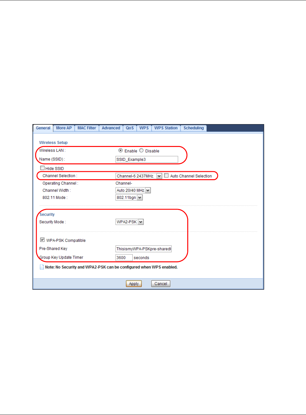
Chapter 6 Tutorials
EMG3425-Q10A User’s Guide
41
Follow the steps below to configure the wireless settings on your EMG3425-Q10A.
The instructions require that your hardware is connected (see the Quick Start Guide) and you are
logged into the Web Configurator through your LAN connection (see Section 2.3 on page 19).
1Make sure the W I FI switch (at the back panel of the EMG3425-Q10A) is set to ON .
2Open the Con figura t ion > N e t w or k > W ireless LAN 2 .4 G > Genera l screen in the AP’s Web
Configurator.
3Confirm that the wireless LAN is enabled on the EMG3425-Q10A.
4Enter SSI D _ Ex a m ple 3 as the SSID and select Channel- 0 6 as the channel. Set security mode to
W PA2 - PSK and enter Thisism y W PA- PSKpr e- sh aredkey in the Pre- Sha r ed Key field. Click
Apply.
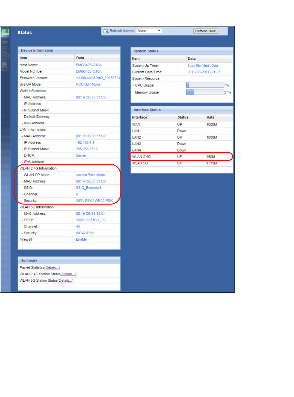
Chapter 6 Tutorials
EMG3425-Q10A User’s Guide
42
5Open the St a t us screen. Verify your wireless and wireless security settings under De vice
I n for m a t io n and check if the WLAN connection is up under I nt e r face Stat us.
6.3.1 Configure Your Notebook
Note: In this example, we use the ZyXEL NWD6505 wireless adapter as the wireless
client and use the Windows built-in utility (Windows Zero Configuration (WZC)) to
connect to the wireless netwok.
1The EMG3425-Q10A supports IEEE 802.11a, IEEE 802.11b, IEEE 802.11g, IEEE 802.11n and IEEE
802.11ac wireless clients. Make sure that your notebook or computer’s wireless adapter supports
one of these standards.
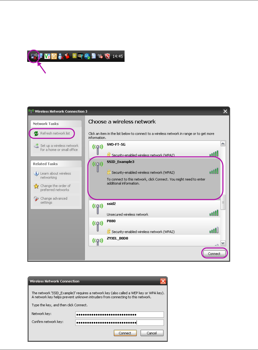
Chapter 6 Tutorials
EMG3425-Q10A User’s Guide
43
2Wireless adapters come with software sometimes called a “utility” that you install on your
computer. See your wireless adapter’s User’s Guide for information on how to do that.
3After you’ve installed the driver and attached the NWD6505 to your computer’s USB port, right-
click the W ireless N e t w ork Connect ion icon in your computer’s system tray, select and click
View Ava ilable W ir e less N e tw orks.
4The W ireless N e tw ork Connect ion screen displays. Click Refresh net w ork list to view the
available wireless APs within range.
5Select SSI D _ Ex a m p le 3 and click Con ne ct .
6Type the security key in the following screen. Click Connect.
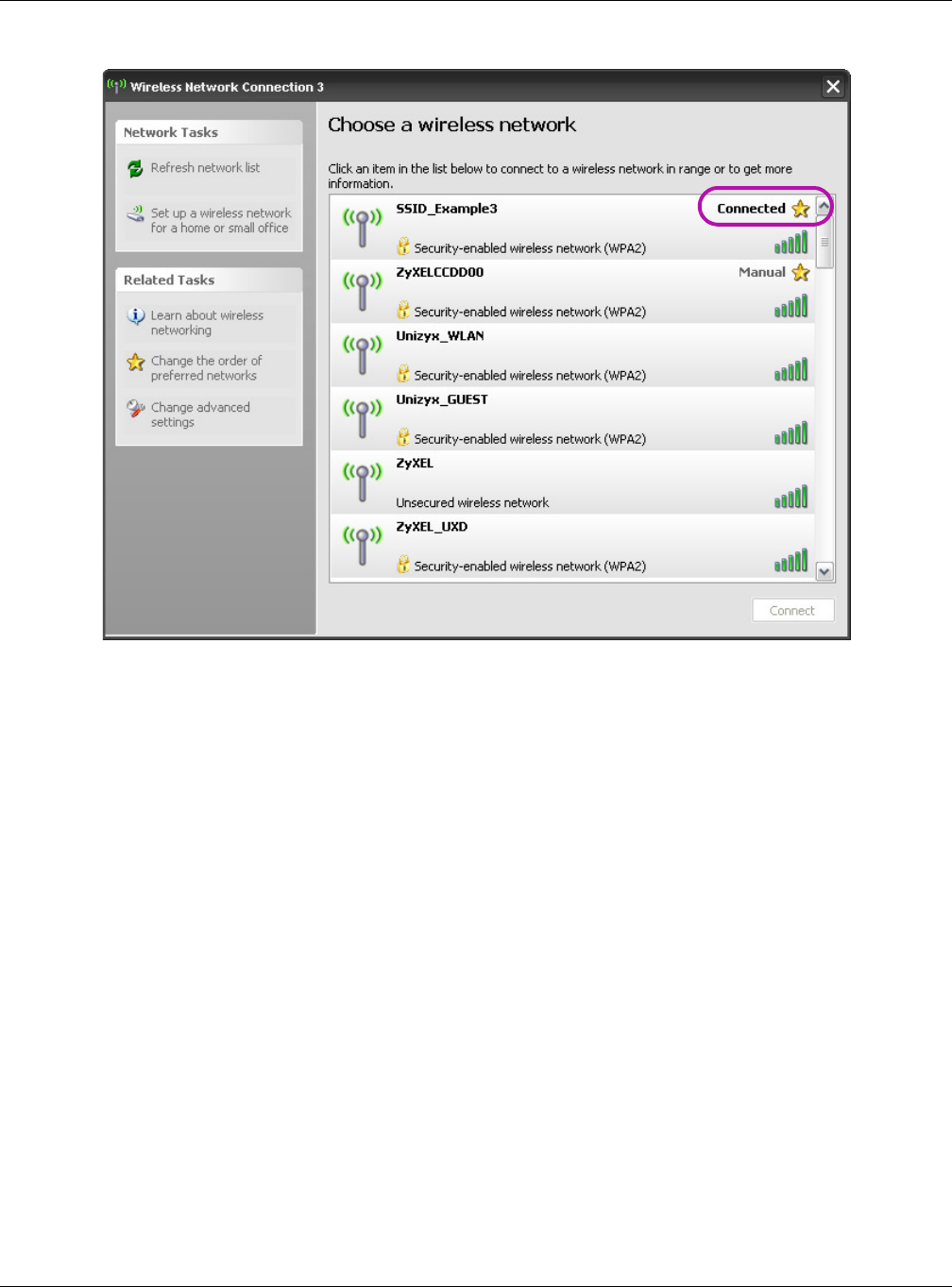
Chapter 6 Tutorials
EMG3425-Q10A User’s Guide
44
7Check the status of your wireless connection in the screen below.
8If the wireless client keeps trying to connect to or acquiring an IP address from the EMG3425-
Q10A, make sure you entered the correct security key.
If the connection has limited or no connectivity, make sure the DHCP server is enabled on the
EMG3425-Q10A.
If your connection is successful, open your Internet browser and enter http://www.zyxel.com or the
URL of any other web site in the address bar. If you are able to access the web site, your wireless
connection is successfully configured.
6.4 Using Multiple SSIDs on the EMG3425-Q10A
You can configure more than one SSID on a EMG3425-Q10A. See Section 9.4 on page 79.
This allows you to configure multiple independent wireless networks on the EMG3425-Q10A as if
there were multiple APs (virtual APs). Each virtual AP has its own SSID, wireless security type and
MAC filtering settings. That is, each SSID on the EMG3425-Q10A represents a different access
point/wireless network to wireless clients in the network.
Clients can associate only with the SSIDs for which they have the correct security settings. Clients
using different SSIDs can access the Internet and the wired network behind the EMG3425-Q10A
(such as a printer).
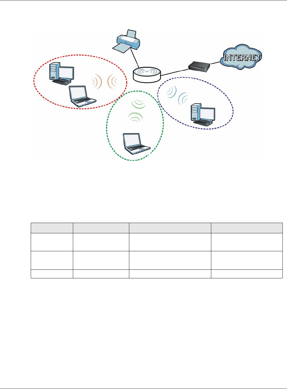
Chapter 6 Tutorials
EMG3425-Q10A User’s Guide
45
For example, you may set up three wireless networks (A, B and C) in your office. A is for workers,
B is for guests and C is specific to a VoIP device in the meeting room.
6.4.1 Configuring Security Settings of Multiple SSIDs
The EMG3425-Q10A is in router mode by default.
This example shows you how to configure the SSIDs with the following parameters on your
EMG3425-Q10A (in router mode).
1Connect your computer to the LAN port of the EMG3425-Q10A using an Ethernet cable.
2The default IP address of the EMG3425-Q10A in router mode is “192.168.1.1”. In this case, your
computer must have an IP address in the range between “192.168.1.2” and “192.168.1.254”.
3Click St art > Run on your computer in Windows. Type “cmd” in the dialog box. Enter “ipconfig” to
show your computer’s IP address. If your computer’s IP address is not in the correct range then see
Appendix B on page 203 for information on changing your computer’s IP address.
4After you’ve set your computer’s IP address, open a web browser such as Internet Explorer and
type “http://192.168.1.1” as the web address in your web browser.
5Enter “1234” (default) as the password and click Login.
A
B
C
SSI D_ Guest
SSI D _ W orke r
SSI D _ VoI P
SSID SECURITY TYPE KEY MAC FILTERING
SSID_Worker WPA2-PSK
WPA Compatible
DoNotStealMyWirelessNetwork Disable
SSID_VoIP WPA-PSK VoIPOnly12345678 Allow
00:A0:C5:01:23:45
SSID_Guest WPA-PSK keyexample123 Disable
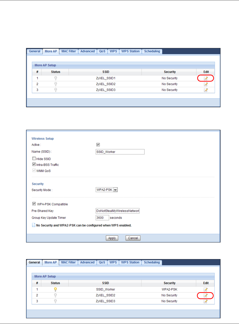
Chapter 6 Tutorials
EMG3425-Q10A User’s Guide
46
6Type a new password and retype it to confirm, then click Apply. Otherwise, click I gnore.
7The Ea sy Mode appears. Click Expert M ode in the navigation panel.
8Go to Configu r a t ion > Net w or k > W ir e less LAN 2 .4 G > M ore AP. Click the Edit icon of the first
entry to configure wireless and security settings for SSI D_ W ork e r.
9Configure the screen as follows. In this example, you enable I nt ra- BSS Tr affic for SSI D_ W orker
to allow wireless clients in the same wireless network to communicate with each other. Click Apply.
10 Click the Ed it icon of the second entry to configure wireless and security settings for SSI D_ VoI P.
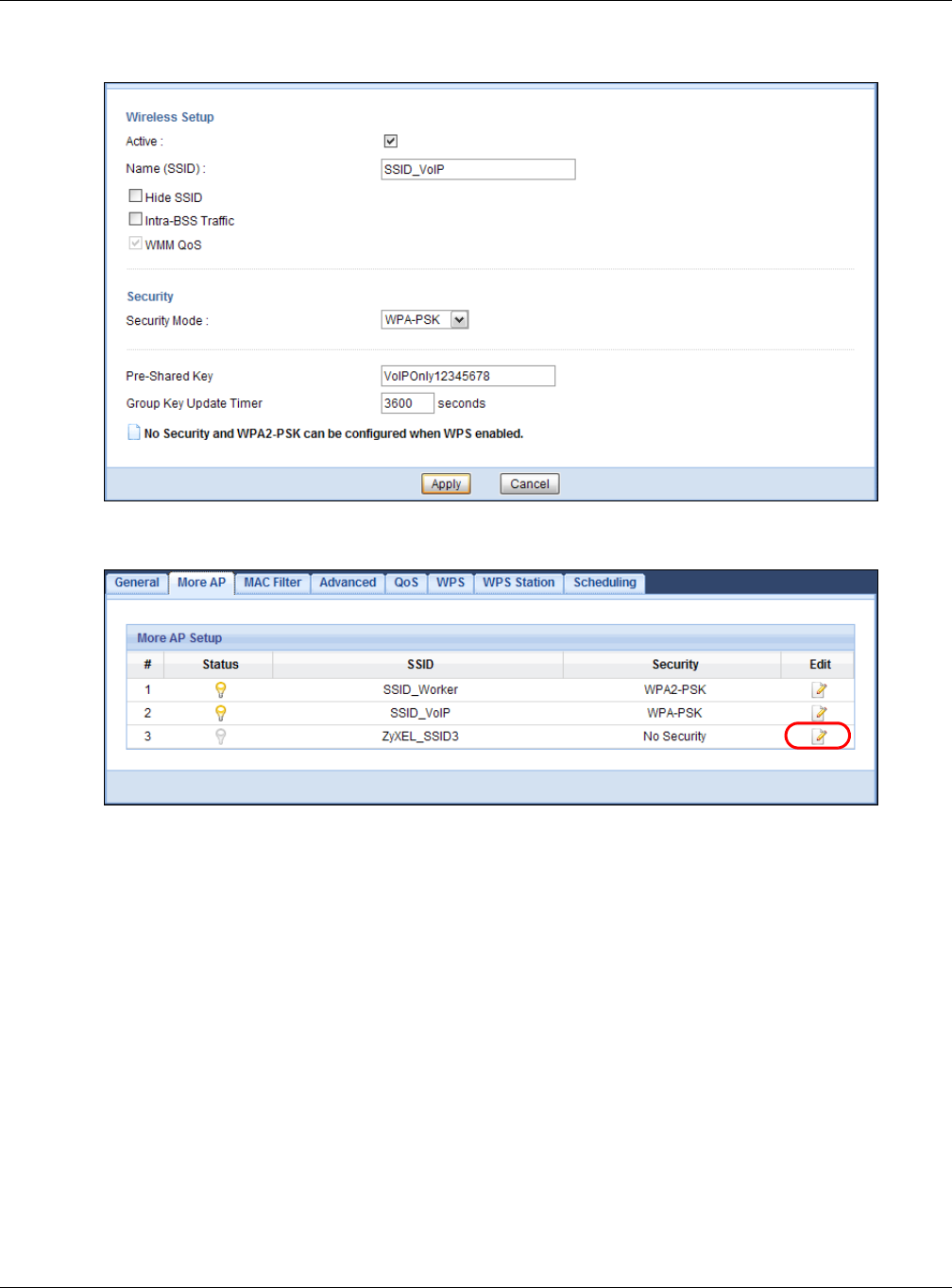
Chapter 6 Tutorials
EMG3425-Q10A User’s Guide
47
11 Configure the screen as follows. You do not enable I nt ra- BSS Traffic for SSI D _ VoI P. Click Apply.
12 Click the Ed it icon of the third entry to configure wireless and security settings for SSI D _ Gu e st .
13 Configure the screen as follows. In this example, you enable I ntr a - BSS Traffic for SSI D_ Gu est to
allow wireless clients in the same wireless network to communicate with each other. Select Enable
Guest W LAN to allow clients to access the Internet only. Click Apply.
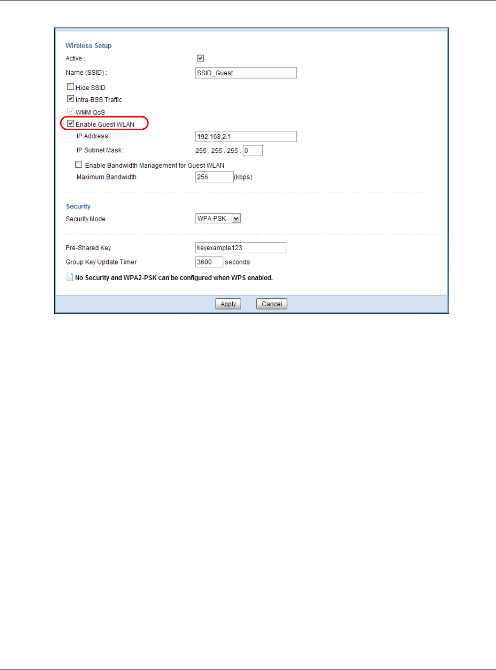
Chapter 6 Tutorials
EMG3425-Q10A User’s Guide
48
14 Click the M AC Filt er tab to configure MAC filtering for the SSI D _ VoI P wireless network. Select
SSI D_ V oI P from the SSI D Select drop-down list, enable MAC address filtering and set the Filt e r
Act ion to Allow . Enter the VoIP device’s MAC address in the Mac Address field and click Apply to
allow only the VoIP device to associate with the EMG3425-Q10A using this SSID.
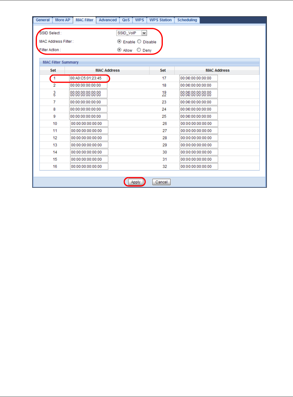
Chapter 6 Tutorials
EMG3425-Q10A User’s Guide
49

50
PART II
Technical Reference
EMG3425-Q10A User’s Guide
51
CHAPTER 7
Monitor
7.1 Overview
This chapter discusses read-only information related to the device state of the EMG3425-Q10A.
To access the Monitor screens, go to Ex per t M ode after login, then click .
You can also click the links in the Sum m ary table of the St a t u s screen to view the packets sent/
received as well as the status of clients connected to the EMG3425-Q10A.
7.2 What You Can Do
•Use the Log screen to see the logs for the activity on the EMG3425-Q10A (Section 7.3 on page
51).
•Use the DHCP Table screen to view information related to your DHCP status (Section 7.4 on
page 52).
•use the Pa cke t St a t ist ics screen to view port status, packet specific statistics, the "system up
time" and so on (Section 7.5 on page 53).
•Use the W LAN 2 .4 G/ 5 G St at ion Sta t us screen to view the wireless stations that are currently
associated to the EMG3425-Q10A (Section 7.6 on page 54).
•Use the I GM P Stat ist ics screen (Section 7.7 on page 55) to view multicasting details.
7.3 The Log Screen
The Web Configurator allows you to look at all of the EMG3425-Q10A’s logs in one location.
7.3.1 View Log
Use the Vie w Log screen to see the logged messages for the EMG3425-Q10A. The log wraps
around and deletes the old entries after it fills. Select what logs you want to see from the Display
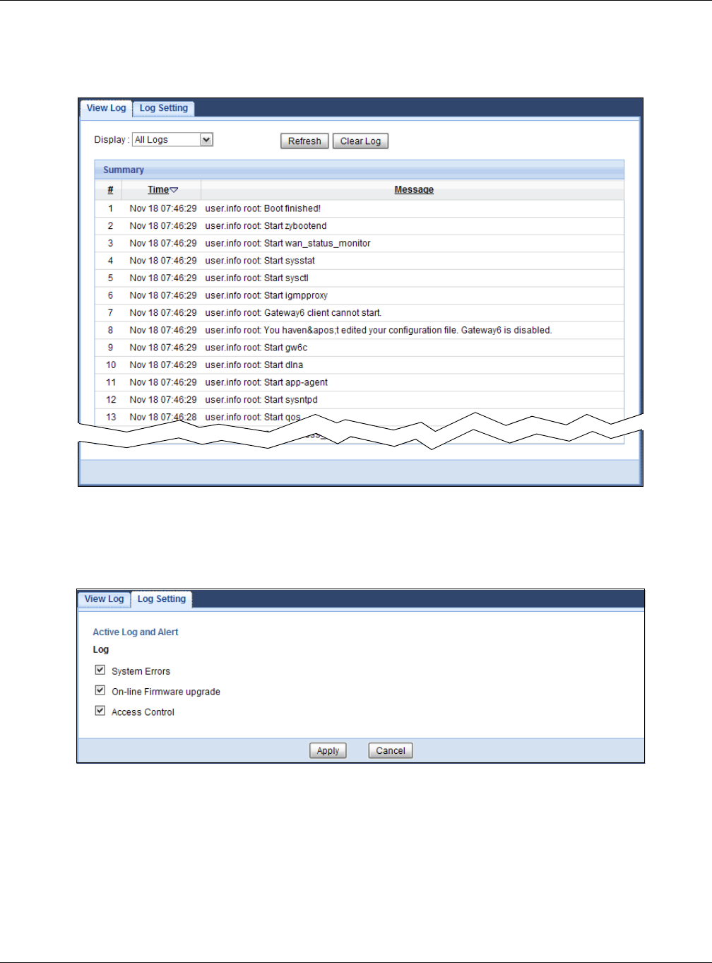
Chapter 7 Monitor
EMG3425-Q10A User’s Guide
52
drop list. The log choices depend on your settings in the Log Se t t ing screen. Click Refr e sh to
renew the log screen. Click Clear Log to delete all the logs.
Figure 19 View Log
You can configure which logs to display in the View Log screen. Go to the Log Sett ing screen and
select the logs you wish to display. Click Apply to save your settings. Click Cancel to start the
screen afresh.
Figure 20 Log Settings
7.4 DHCP Table
DHCP (Dynamic Host Configuration Protocol, RFC 2131 and RFC 2132) allows individual clients to
obtain TCP/IP configuration at start-up from a server. You can configure the EMG3425-Q10A’s LAN
as a DHCP server or disable it. When configured as a server, the EMG3425-Q10A provides the TCP/
IP configuration for the clients. If DHCP service is disabled, you must have another DHCP server on
that network, or else the computer must be manually configured.
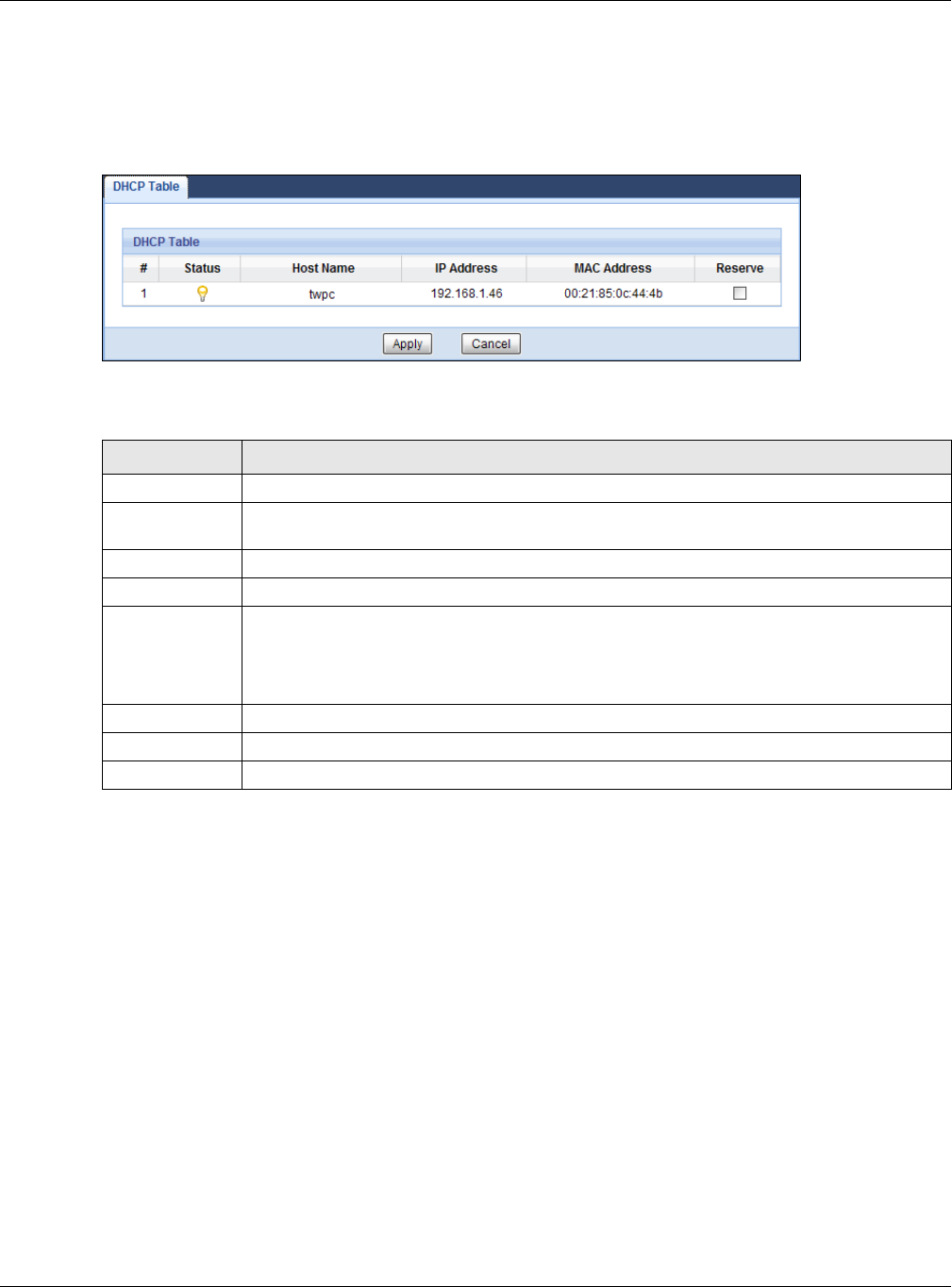
Chapter 7 Monitor
EMG3425-Q10A User’s Guide
53
Click Monit or > DHCP Table or Configurat ion > Net w ork > DHCP Se rver > Client List . Read-
only information here relates to your DHCP status. The DHCP table shows current DHCP client
information (including M AC Addr e ss, and I P Addr ess) of all network clients using the EMG3425-
Q10A’s DHCP server.
Figure 21 Monitor > DHCP Table
The following table describes the labels in this screen.
7.5 Packet Statistics
Click M onit or > Pa cket St at ist ics or the Packet St a t ist ics ( Det ails...) hyperlink in the Sta t us
screen. Read-only information here includes port status, packet specific statistics and the "system
up time". The Poll I nt erval( s) field is configurable and is used for refreshing the screen.
Table 11 Monitor > DHCP Table
LABEL DESCRIPTION
# This is the index number of the host computer.
Status This field displays whether the connection to the host computer is up (a yellow bulb) or
down (a gray bulb).
Host Name This field displays the computer host name.
IP Address This field displays the IP address relative to the # field listed above.
MAC Address This field shows the MAC address of the computer with the name in the Host Nam e field.
Every Ethernet device has a unique MAC (Media Access Control) address which uniquely
identifies a device. The MAC address is assigned at the factory and consists of six pairs of
hexadecimal characters, for example, 00:A0:C5:00:00:02.
Reserve Select this if you want to reserve the IP address for this specific MAC address.
Apply Click Apply to save your changes back to the EMG3425-Q10A.
Cancel Click Cancel to reload the previous configuration for this screen.
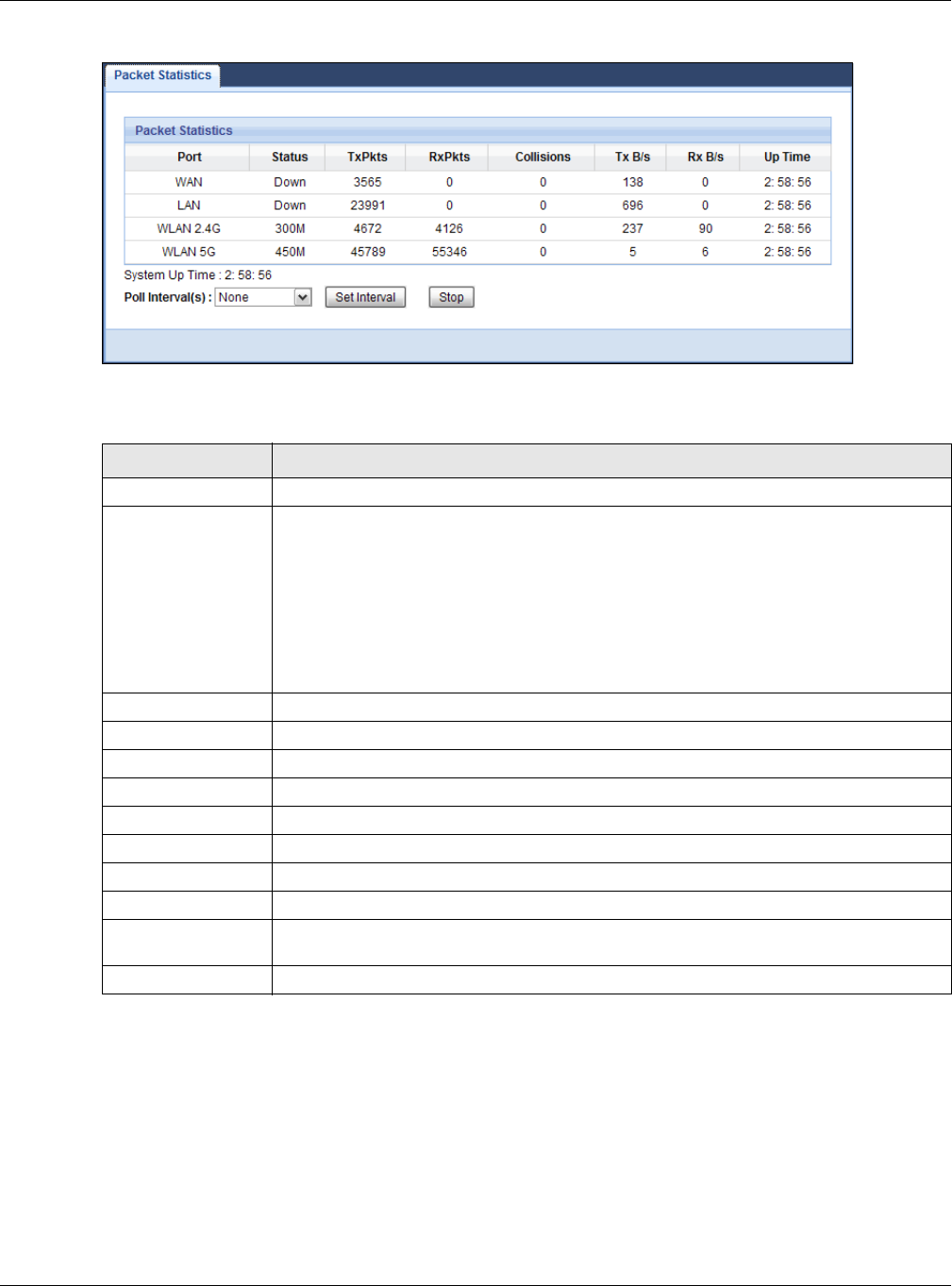
Chapter 7 Monitor
EMG3425-Q10A User’s Guide
54
Figure 22 Monitor > Packet Statistics
The following table describes the labels in this screen.
7.6 WLAN Station Status
Click M onit or > W LAN 2 .4 G/ 5 G St a t ion St at us or the W LAN 2 .4 G/ 5 G St at ion St a t us
( D e t ails. ..) hyperlink in the St a t us screen. View the wireless stations that are currently associated
to the EMG3425-Q10A’s 2.4GHz or 5GHz wireless network in the Association List. Association
means that a wireless client (for example, your network or computer with a wireless network card)
has connected successfully to the AP (or wireless router) using the same SSID, channel and
security settings.
Table 12 Monitor > Packet Statistics
LABEL DESCRIPTION
Port This is the EMG3425-Q10A’s interface type.
Status For the LAN ports, this displays the port speed and duplex setting or Dow n when the
line is disconnected.
For the WAN port, it displays the port speed and duplex setting if you’re using Ethernet
encapsulation and I dle (line (ppp) idle), Dial (starting to trigger a call) and Drop
(dropping a call) if you're using PPPoE encapsulation. This field displays Dow n when
the line is disconnected.
For the 2.4GHz or 5GHz WLAN, it displays the maximum transmission rate when the
WLAN is enabled and D ow n when the WLAN is disabled.
TxPkts This is the number of transmitted packets on this port.
RxPkts This is the number of received packets on this port.
Collisions This is the number of collisions on this port.
Tx B/s This displays the transmission speed in bytes per second on this port.
Rx B/s This displays the reception speed in bytes per second on this port.
Up Time This is the total time the EMG3425-Q10A has been for each session.
System Up Time This is the total time the EMG3425-Q10A has been on.
Poll Interval(s) Enter the time interval in seconds for refreshing statistics in this field.
Set Interval Click this button to apply the new poll interval you entered in the Poll I nt erva l( s)
field.
Stop Click St op to stop refreshing statistics.
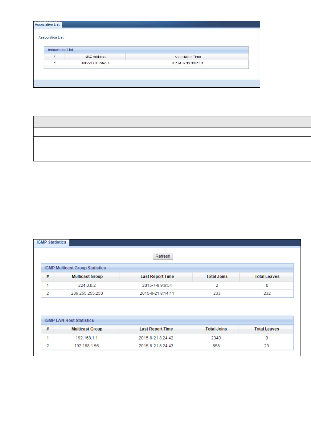
Chapter 7 Monitor
EMG3425-Q10A User’s Guide
55
Figure 23 Monitor > WLAN Station Status
The following table describes the labels in this screen.
7.7 IGMP Statistics
Use this screen to look at the current number of IGMP-related packets received for each IGMP
multicast group and from each LAN host. Click Mon itor > I GMP St a t ist ics to open the following
screen.
Figure 24 Monitor > IGMP Statistics
Table 13 Monitor > WLAN Station Status
LABEL DESCRIPTION
# This is the index number of an associated wireless station.
MAC Address This field displays the MAC address of an associated wireless station.
Association Time This field displays the time a wireless station first associated with the EMG3425-Q10A’s
WLAN.

Chapter 7 Monitor
EMG3425-Q10A User’s Guide
56
The following table describes the labels in this screen.
Table 14 Monitor > IGMP Statistics
LABEL DESCRIPTION
Refresh Click this button to update the information in the screen.
IGMP Multicast Group Statistics
This section shows statistics about the number of IGMP-related packets received for each IGMP multicast
group.
# This field is a sequential value, and it is not associated with a specific IGMP Statistics.
Multicast Group This field displays the IP address of the IGMP multicast group for which the EMG3425-
Q10A received IGMP-related packets.
Last Report Time This field displays when the EMG3425-Q10A received the latest packet for this IGMP
multicast group.
Total Joins This field displays the total number of Join packets the EMG3425-Q10A has received for
this IGMP multicast group.
Total Leave s This field displays the total number of Leave packets the EMG3425-Q10A has received
for this IGMP multicast group.
IGMP LAN Host Statistics
This section shows statistics about the number of IGMP-related packets received from each LAN host.
# This field is a sequential value, and it is not associated with a specific IGMP Statistics.
Multicast Group This field displays the IP address of a LAN computer that has sent the EMG3425-Q10A
IGMP-related packets.
Last Report Time This field displays when the EMG3425-Q10A received the latest packet from this LAN IP
address for this IGMP multicast group.
Total Joins This field displays the total number of Join packets the EMG3425-Q10A has received
from this LAN IP address.
Total Leave s This field displays the total number of Leave packets the EMG3425-Q10A has received
from this LAN IP address.
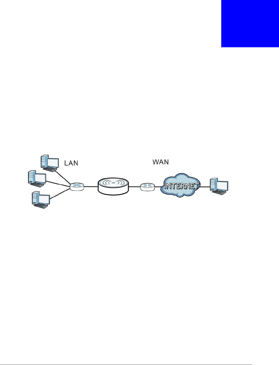
EMG3425-Q10A User’s Guide
57
CHAPTER 8
WAN
8.1 Overview
This chapter discusses the EMG3425-Q10A’s W AN screens. Use these screens to configure your
EMG3425-Q10A for Internet access.
A WAN (Wide Area Network) connection is an outside connection to another network or the
Internet. It connects your private networks such as a LAN (Local Area Network) and other
networks, so that a computer in one location can communicate with computers in other locations.
Figure 25 LAN and WAN
8.2 What You Can Do
•Use the I nt er n e t Connection screen to enter your ISP information and set how the computer
acquires its IP, DNS and WAN MAC addresses (Section 8.4 on page 59).
8.3 What You Need To Know
The information in this section can help you configure the screens for your WAN connection, as well
as enable/disable some advanced features of your EMG3425-Q10A.
8.3.1 Configuring Your Internet Connection
Encapsulation Method
Encapsulation is used to include data from an upper layer protocol into a lower layer protocol. To set
up a WAN connection to the Internet, you need to use the same encapsulation method used by your
ISP (Internet Service Provider). If your ISP offers a dial-up Internet connection using PPPoE (PPP

Chapter 8 WAN
EMG3425-Q10A User’s Guide
58
over Ethernet) or PPTP (Point-to-Point Tunneling Protocol), they should also provide a username
and password (and service name) for user authentication.
WAN IP Address
The WAN IP address is an IP address for the EMG3425-Q10A, which makes it accessible from an
outside network. It is used by the EMG3425-Q10A to communicate with other devices in other
networks. It can be static (fixed) or dynamically assigned by the ISP each time the EMG3425-Q10A
tries to access the Internet.
If your ISP assigns you a static WAN IP address, they should also assign you the subnet mask and
DNS server IP address(es) (and a gateway IP address if you use the Ethernet or ENET ENCAP
encapsulation method).
DNS Server Address Assignment
Use Domain Name System (DNS) to map a domain name to its corresponding IP address and vice
versa, for instance, the IP address of www.zyxel.com is 204.217.0.2. The DNS server is extremely
important because without it, you must know the IP address of a computer before you can access
it.
The EMG3425-Q10A can get the DNS server addresses in the following ways.
1The ISP tells you the DNS server addresses, usually in the form of an information sheet, when you
sign up. If your ISP gives you DNS server addresses, manually enter them in the DNS server fields.
2If your ISP dynamically assigns the DNS server IP addresses (along with the EMG3425-Q10A’s WAN
IP address), set the DNS server fields to get the DNS server address from the ISP.
WAN MAC Address
The MAC address screen allows users to configure the WAN port's MAC address by either using the
factory default or cloning the MAC address from a computer on your LAN. Choose Fa ctory Default
to select the factory assigned default MAC Address.
Otherwise, click Clone t he com pute r 's M AC addr e ss - I P Address and enter the IP address of
the computer on the LAN whose MAC you are cloning. Once it is successfully configured, the
address will be copied to configuration file. It is recommended that you clone the MAC address prior
to hooking up the WAN Port.

Chapter 8 WAN
EMG3425-Q10A User’s Guide
59
Multicast
Traditionally, IP packets are transmitted in one of either two ways - Unicast (1 sender - 1 recipient)
or Broadcast (1 sender - everybody on the network). Multicast delivers IP packets to a group of
hosts on the network - not everybody and not just 1.
Figure 26 Multicast Example
In the multicast example above, systems A and D comprise one multicast group. In multicasting,
the server only needs to send one data stream and this is delivered to systems A and D.
IGMP (Internet Group Multicast Protocol) is a network-layer protocol used to establish membership
in a multicast group - it is not used to carry user data. The EMG3425-Q10A supports both IGMP
version 1 (I GMP- v 1 ) and IGMP version 2 (I GM P- v2 ).
At start up, the EMG3425-Q10A queries all directly connected networks to gather group
membership. After that, the EMG3425-Q10A periodically updates this information. IP multicasting
can be enabled/disabled on the EMG3425-Q10A WAN interface in the Web Configurator (W AN ).
Select N one to disable IP multicasting on these interfaces.
8.4 Management WAN
Use this screen to view, change, or add your EMG3425-Q10A’s Internet access settings. Click
Configura t ion > N e t w ork > W AN . The following screen opens.
Figure 27 Network > WAN > Management WAN

Chapter 8 WAN
EMG3425-Q10A User’s Guide
60
The following table describes the labels in this screen.
8.4.1 Add/Edit WAN Connection
Click the Add N e w W AN Entrie s in the Configurat ion > W AN screen or the Edit icon next to
theconnection you want to configure. Use this screen to configure a WAN connection. The screen
varies depending on the encapsulation you select.
8.4.1.1 IPoE Encapsulation
This screen displays when you select I PoE encapsulation.
Table 15 Network > WAN > Management WAN
LABEL DESCRIPTION
Add New WAN
Entries
Click this to create a new WAN interface entry.
#This is the index number of the connection.
Default Select the WAN interface that you want to configure as default.
Name This is the service name of the connection.
Interface This is the interface of the connection.
Type This shows the type of interface used by this connection.
VLAN ID This indicates the VLAN ID number assigned to traffic sent through this connection.
IP Address This is the WAN IP address used by this connection.
Status This shows the status of the connection.
Modify Click the Edit icon to configure the connection.
Click the Dele t e icon to delete this connection from the EMG3425-Q10A. A window
displays asking you to confirm that you want to delete the connection.
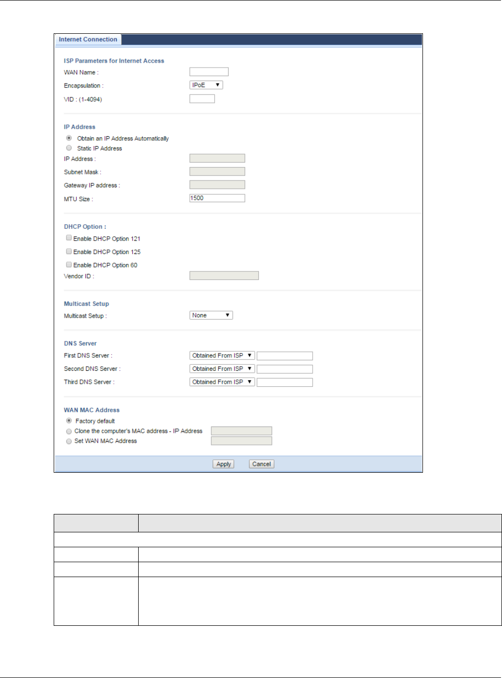
Chapter 8 WAN
EMG3425-Q10A User’s Guide
61
Figure 28 Network > WAN > Internet Connection: IPoE Encapsulation (IPv4 Only)
The following table describes the labels in this screen.
Table 16 Network > WAN > Internet Connection: IPoE Encapsulation
LABEL DESCRIPTION
ISP Parameters for Internet Access
WAN Name Enter the name to use for this connection definition.
Encapsulation You must choose the I PoE option when the WAN port is used as a regular Ethernet.
IPv4 / IPv6 Select I Pv4 Only if you want the EMG3425-Q10A to run IPv4 only.
Select Dual Stack to allow the EMG3425-Q10A to run IPv4 and IPv6 at the same time.
Select I Pv6 Only if you want the EMG3425-Q10A to run IPv6 only.

Chapter 8 WAN
EMG3425-Q10A User’s Guide
62
VID Enter a VLAN identifier between 11 to 4094 (the 802.1Q tag specifies only a priority and
is referred to as a priority tag).
VID 1 (the default VLAN ID) is reserved for a management VLAN.
Note: This field is not available when you are configuring the default WAN entry.
IP Address
This is not available when you select I Pv6 On ly in the I Pv6 / I Pv4 field.
Obtain an IP
Address
Automatically
Select this option If your ISP did not assign you a fixed IP address. This is the default
selection.
Static IP Address Select this option If the ISP assigned a fixed IP address.
IP Address Enter your WAN IP address in this field if you selected St a t ic I P Address.
Subnet Mask Enter the Su bne t Mask in this field.
Gateway IP
Address Enter a Ga t ew ay I P Address (if your ISP gave you one) in this field.
MTU Size Enter the MTU (Maximum Transmission Unit) size for each packet. If a larger packet
arrives, the EMG3425-Q10A divides it into smaller fragments.
DHCP Option
This is not available when you select I Pv6 On ly in the I Pv6 / I Pv4 field.
Enable DHCP
Option 121
Select this to enable the classless route option 121.
Enable DHCP
Option 125
Select this to add vendor specific information to DHCP requests that the EMG3425-Q10A
sends to a DHCP server when getting a WAN IP address.
Enable DHCP
Option 60
Select this to identify the vendor and functionality of the EMG3425-Q10A in DHCP
requests that the EMG3425-Q10A sends to a DHCP server when getting a WAN IP
address.
Vendor ID Enter the Vendor Class Identifier (Option 60), such as the type of hardware or firmware.
6RD
Use IPv6 Rapid Deployment (6rd) when the local network uses IPv6 and the ISP has an IPv4 network. When
the EMG3425-Q10A has an IPv4 WAN address and you set IPv6/IPv4 mode to I Pv4 Only, you can enable 6rd
to encapsulate IPv6 packets in IPv4 packets to cross the ISP’s IPv4 network.
The EMG3425-Q10A generates a global IPv6 prefix from its IPv4 WAN address and tunnels IPv6 traffic to the
ISP’s Border Relay router to connect to the native IPv6 Internet. The local network can also use IPv4 services.
The EMG3425-Q10A uses its configured IPv4 WAN IP to route IPv4 traffic to the IPv4 Internet.
This is available only when you select I Pv4 Only in the I Pv6 / I Pv4 field.
Enable 6RD Enable IPv6 rapid deployment to tunnel IPv6 traffic from the local network through the
ISP’s IPv4 network.
Automatically
configured by
DHCPC
Select this to have the EMG3425-Q10A detect the relay server’s IP address automatically
through DHCP.
Manually
Configured
Select this if you have the IPv4 address of the relay server.
Border Relay IPv4
Address
Specify the relay server’s IPv4 address.
Service Provider
IPv6 Prefix
Enter an IPv6 prefix for tunneling IPv6 traffic to the ISP’s Border Relay router and
connecting to the native IPv6 Internet.
Table 16 Network > WAN > Internet Connection: IPoE Encapsulation (continued)
LABEL DESCRIPTION

Chapter 8 WAN
EMG3425-Q10A User’s Guide
63
8.4.1.2 PPPoE Encapsulation
The EMG3425-Q10A supports PPPoE (Point-to-Point Protocol over Ethernet). PPPoE is an IETF
standard (RFC 2516) specifying how a personal computer (PC) interacts with a broadband modem
Service Provider
IPv6 Prefix length
Enter the IPv6 prefix length.
An IPv6 prefix length specifies how many most significant bits (starting from the left) in
the address compose the network address.
IPv4 mask length Enter the subnet mask number (1~32) for the IPv4 network.
DNS Server
First DNS Server
Second DNS
Server
Third DNS Server
Select Obtained From I SP if your ISP dynamically assigns DNS server information (and
the EMG3425-Q10A's WAN IP address). The field to the right displays the (read-only)
DNS server IP address that the ISP assigns.
Select User- Defin ed if you have the IP address of a DNS server. Enter the DNS server's
IP address in the field to the right.
Select N on e if you do not want to configure DNS servers. If you do not configure a DNS
server, you must know the IP address of a computer in order to access it.
WAN MAC Address The MAC address section allows users to configure the WAN port's MAC address by using
the EMG3425-Q10A’s MAC address, copying the MAC address from a computer on your
LAN or manually entering a MAC address.
Factory default Select Fa ctor y de fault to use the factory assigned default MAC Address.
Clone the
computer’s MAC
address - IP
Address
Select Clone t he com put er's M AC a ddr e ss - I P Addre ss and enter the IP address of
the computer on the LAN whose MAC you are cloning.
Set WAN MAC
Address
Select this option and enter the MAC address you want to use.
IPv6 Address This is not available when you select I Pv4 Only in the I Pv6 / I Pv4 field.
Obtain an IP
Address
Automatically
Select this if you want to obtain an IPv6 address from a DHCPv6 server.
Static IP Address Select this if you have a fixed IPv6 address assigned by your ISP.
IPv6 Address Enter the IPv6 address assigned by your ISP.
Prefix length Enter the address prefix length to specify how many most significant bits in an IPv6
address compose the network address.
IPv6 Default
Gateway Enter the IP address of the next-hop gateway. The gateway is a router or switch on the
same segment as your EMG3425-Q10A's interface(s). The gateway helps forward
packets to their destinations.
IPv6 DNS server
This is not available when you select I Pv4 On ly in the I Pv6 / I Pv4 field.
Obtain IPv6 DNS
info Automatically
Select this to have the EMG3425-Q10A get the IPv6 DNS server addresses from the ISP
automatically.
Use the following
Static DNS IPv6
Address
Select this to have the EMG3425-Q10A use the IPv6 DNS server addresses you configure
manually.
IPv6 DNS Server Enter the IPv6 DNS server address assigned by the ISP.
Apply Click Apply to save your changes back to the EMG3425-Q10A.
Cancel Click Cancel to begin configuring this screen afresh.
Table 16 Network > WAN > Internet Connection: IPoE Encapsulation (continued)
LABEL DESCRIPTION

Chapter 8 WAN
EMG3425-Q10A User’s Guide
64
(DSL, cable, wireless, etc.) connection. The PPP over Et h e r net option is for a dial-up connection
using PPPoE.
For the service provider, PPPoE offers an access and authentication method that works with existing
access control systems (for example Radius).
One of the benefits of PPPoE is the ability to let you access one of multiple network services, a
function known as dynamic service selection. This enables the service provider to easily create and
offer new IP services for individuals.
Operationally, PPPoE saves significant effort for both you and the ISP or carrier, as it requires no
specific configuration of the broadband modem at the customer site.
By implementing PPPoE directly on the EMG3425-Q10A (rather than individual computers), the
computers on the LAN do not need PPPoE software installed, since the EEMG3425-Q10A does that
part of the task. Furthermore, with NAT, all of the LANs’ computers will have access.
This screen displays when you select PPPoE encapsulation.
Chapter 8 WAN
EMG3425-Q10A User’s Guide
65
Figure 29 Network > WAN > Internet Connection: PPPoE Encapsulation (IPv4 Only)
The following table describes the labels in this screen.
Table 17 Network > WAN > Internet Connection: PPPoE Encapsulation
LABEL DESCRIPTION
ISP Parameters for Internet Access
WAN Name Enter the name to use for this connection definition.
Encapsulation You must choose the PPPoE option when the WAN port is used as a regular Ethernet.
IPv4 / IPv6 Select I Pv4 Only if you want the EMG3425-Q10A to run IPv4 only.
Select Dual Stack to allow the EMG3425-Q10A to run IPv4 and IPv6 at the same time.
Select I Pv6 Only if you want the EMG3425-Q10A to run IPv6 only.

Chapter 8 WAN
EMG3425-Q10A User’s Guide
66
VID Enter a VLAN identifier between 11 to 4094 (the 802.1Q tag specifies only a priority and
is referred to as a priority tag).
VID 1 (the default VLAN ID) is reserved for a management VLAN.
Note: This field is not available when you are configuring the default WAN entry.
PPP Information
PPP Username Type the user name given to you by your ISP.
PPP Password Type the password associated with the user name above.
MTU Size Enter the Maximum Transmission Unit (MTU) or the largest packet size per frame that
your EMG3425-Q10A can receive and process.
PPP Auto Connect Select this option if you do not want the connection to time out.
Idle Timeout
(second)
This value specifies the time in minutes that elapses before the router automatically
disconnects from the PPPoE server.
PPPoE Service
Name
Enter the PPPoE service name specified in the ISP account.
WAN IP Address Assignment
Get automatically
from ISP
Select this option If your ISP did not assign you a fixed IP address. This is the default
selection.
Use Fixed IP
Address
Select this option If the ISP assigned a fixed IP address.
My WAN IP
Address Enter your WAN IP address in this field if you selected Use Fixed I P Address.
6RD
Use IPv6 Rapid Deployment (6rd) when the local network uses IPv6 and the ISP has an IPv4 network. When
the EMG3425-Q10A has an IPv4 WAN address and you set IPv6/IPv4 mode to I Pv4 Only, you can enable 6rd
to encapsulate IPv6 packets in IPv4 packets to cross the ISP’s IPv4 network.
The EMG3425-Q10A generates a global IPv6 prefix from its IPv4 WAN address and tunnels IPv6 traffic to the
ISP’s Border Relay router to connect to the native IPv6 Internet. The local network can also use IPv4 services.
The EMG3425-Q10A uses its configured IPv4 WAN IP to route IPv4 traffic to the IPv4 Internet.
This is available only when you select I Pv4 Only in the I Pv6 / I Pv4 field.
Enable 6RD Enable IPv6 rapid deployment to tunnel IPv6 traffic from the local network through the
ISP’s IPv4 network.
Automatically
configured by
DHCPC
Select this to have the EMG3425-Q10A detect the relay server’s IP address automatically
through DHCP.
Manually
Configured
Select this if you have the IPv4 address of the relay server.
Border Relay IPv4
Address
Specify the relay server’s IPv4 address.
Service Provider
IPv6 Prefix
Enter an IPv6 prefix for tunneling IPv6 traffic to the ISP’s Border Relay router and
connecting to the native IPv6 Internet.
Service Provider
IPv6 Prefix length
Enter the IPv6 prefix length.
An IPv6 prefix length specifies how many most significant bits (starting from the left) in
the address compose the network address.
IPv4 mask length Enter the subnet mask number (1~32) for the IPv4 network.
DNS Server
Table 17 Network > WAN > Internet Connection: PPPoE Encapsulation (continued)
LABEL DESCRIPTION

Chapter 8 WAN
EMG3425-Q10A User’s Guide
67
First DNS Server
Second DNS
Server
Third DNS Server
Select Obtained From I SP if your ISP dynamically assigns DNS server information (and
the EMG3425-Q10A's WAN IP address). The field to the right displays the (read-only)
DNS server IP address that the ISP assigns.
Select User- Defin ed if you have the IP address of a DNS server. Enter the DNS server's
IP address in the field to the right.
Select N on e if you do not want to configure DNS servers. If you do not configure a DNS
server, you must know the IP address of a computer in order to access it.
WAN MAC Address The MAC address section allows users to configure the WAN port's MAC address by using
the EMG3425-Q10A’s MAC address, copying the MAC address from a computer on your
LAN or manually entering a MAC address.
Factory default Select Fa ctor y de fault to use the factory assigned default MAC Address.
Clone the
computer’s MAC
address - IP
Address
Select Clone t he com put er's M AC a ddr e ss - I P Addre ss and enter the IP address of
the computer on the LAN whose MAC you are cloning.
Set WAN MAC
Address
Select this option and enter the MAC address you want to use.
IPv6 DNS server
This is not available when you select I Pv4 On ly in the I Pv6 / I Pv4 field.
Obtain IPv6 DNS
info Automatically
Select this to have the EMG3425-Q10A get the IPv6 DNS server addresses from the ISP
automatically.
Use the following
Static DNS IPv6
Address
Select this to have the EMG3425-Q10A use the IPv6 DNS server addresses you configure
manually.
IPv6 DNS Server Enter the IPv6 DNS server address assigned by the ISP.
Apply Click Apply to save your changes back to the EMG3425-Q10A.
Cancel Click Cancel to begin configuring this screen afresh.
Table 17 Network > WAN > Internet Connection: PPPoE Encapsulation (continued)
LABEL DESCRIPTION
EMG3425-Q10A User’s Guide
68
CHAPTER 9
Wireless LAN
9.1 Overview
This chapter discusses how to configure the wireless network settings in your EMG3425-Q10A. The
EMG3425-Q10A is able to function both 2.4GHz and 5GHz network at the same time. You can have
different wireless and wireless security settings for 2.4GHz and 5GHz wireless LANs. Click
Configura t ion > Ne t w ork > W ir e less LAN 2 .4 G or W ireless LAN 5 G to configure to do so.
See the appendices for more detailed information about wireless networks.
The following figure provides an example of a wireless network.
Figure 30 Example of a Wireless Network
The wireless network is the part in the blue circle. In this wireless network, devices A and B are
called wireless clients. The wireless clients use the access point (AP) to interact with other devices
(such as the printer) or with the Internet. Your EMG3425-Q10A is the AP.

Chapter 9 Wireless LAN
EMG3425-Q10A User’s Guide
69
9.1.1 What You Can Do
•Use the Ge n e r a l screen to turn the wireless connection on or off, set up wireless security
between the EMG3425-Q10A and the wireless clients, and make other basic configuration
changes (Section 9.2 on page 73).
•Use the More AP screen to set up multiple wireless networks on your EMG3425-Q10A (Section
9.4 on page 79).
•Use the MAC Filte r screen to allow or deny wireless stations based on their MAC addresses from
connecting to the EMG3425-Q10A (Section 9.5 on page 81).
•Use the Advanced screen to allow intra-BSS networking and set the RTS/CTS Threshold (Section
9.6 on page 83).
•Use the QoS screen to ensure Quality of Service (QoS) in your wireless network (Section 9.7 on
page 83).
•Use the W PS screen to quickly set up a wireless network with strong security, without having to
configure security settings manually (Section 9.8 on page 84).
•Use the W PS St at ion screen to add a wireless station using WPS (Section 9.9 on page 86).
•Use the Schedu ling screen to set the times your wireless LAN is turned on and off (Section 9.10
on page 86).
9.1.2 What You Should Know
Every wireless network must follow these basic guidelines.
• Every wireless client in the same wireless network must use the same SSID.
The SSID is the name of the wireless network. It stands for Service Set IDentity.
• If two wireless networks overlap, they should use different channels.
Like radio stations or television channels, each wireless network uses a specific channel, or
frequency, to send and receive information.
• Every wireless client in the same wireless network must use security compatible with the AP.
Security stops unauthorized devices from using the wireless network. It can also protect the
information that is sent in the wireless network.
Wireless Security Overview
The following sections introduce different types of wireless security you can set up in the wireless
network.
SSID
Normally, the AP acts like a beacon and regularly broadcasts the SSID in the area. You can hide the
SSID instead, in which case the AP does not broadcast the SSID. In addition, you should change
the default SSID to something that is difficult to guess.
This type of security is fairly weak, however, because there are ways for unauthorized devices to
get the SSID. In addition, unauthorized devices can still see the information that is sent in the
wireless network.

Chapter 9 Wireless LAN
EMG3425-Q10A User’s Guide
70
MAC Address Filter
Every wireless client has a unique identification number, called a MAC address.1 A MAC address is
usually written using twelve hexadecimal characters2; for example, 00A0C5000002 or
00:A0:C5:00:00:02. To get the MAC address for each wireless client, see the appropriate User’s
Guide or other documentation.
You can use the MAC address filter to tell the AP which wireless clients are allowed or not allowed to
use the wireless network. If a wireless client is allowed to use the wireless network, it still has to
have the correct settings (SSID, channel, and security). If a wireless client is not allowed to use the
wireless network, it does not matter if it has the correct settings.
This type of security does not protect the information that is sent in the wireless network.
Furthermore, there are ways for unauthorized devices to get the MAC address of an authorized
wireless client. Then, they can use that MAC address to use the wireless network.
User Authentication
You can make every user log in to the wireless network before they can use it. This is called user
authentication. However, every wireless client in the wireless network has to support IEEE 802.1x
to do this.
For wireless networks, there are two typical places to store the user names and passwords for each
user.
• In the AP: this feature is called a local user database or a local database.
• In a RADIUS server: this is a server used in businesses more than in homes.
If your AP does not provide a local user database and if you do not have a RADIUS server, you
cannot set up user names and passwords for your users.
Unauthorized devices can still see the information that is sent in the wireless network, even if they
cannot use the wireless network. Furthermore, there are ways for unauthorized wireless users to
get a valid user name and password. Then, they can use that user name and password to use the
wireless network.
Local user databases also have an additional limitation that is explained in the next section.
Encryption
Wireless networks can use encryption to protect the information that is sent in the wireless
network. Encryption is like a secret code. If you do not know the secret code, you cannot
understand the message.
1. Some wireless devices, such as scanners, can detect wireless networks but cannot use wireless networks. These kinds
of wireless devices might not have MAC addresses.
2. Hexadecimal characters are 0, 1, 2, 3, 4, 5, 6, 7, 8, 9, A, B, C, D, E, and F.

Chapter 9 Wireless LAN
EMG3425-Q10A User’s Guide
71
The types of encryption you can choose depend on the type of user authentication. (See page 70
for information about this.)
For example, if the wireless network has a RADIUS server, you can choose W PA or W PA2 . If users
do not log in to the wireless network, you can choose no encryption, St at ic W EP, W PA- PSK, or
W PA2 - PSK.
Usually, you should set up the strongest encryption that every wireless client in the wireless
network supports. For example, suppose the AP does not have a local user database, and you do
not have a RADIUS server. Therefore, there is no user authentication. Suppose the wireless network
has two wireless clients. Device A only supports WEP, and device B supports WEP and WPA.
Therefore, you should set up St a t ic W EP in the wireless network.
Note: It is recommended that wireless networks use W PA- PSK, W PA, or stronger
encryption. IEEE 802.1x and WEP encryption are better than none at all, but it is
still possible for unauthorized devices to figure out the original information pretty
quickly.
Note: It is not possible to use W PA- PSK, W PA or stronger encryption with a local user
database. In this case, it is better to set up stronger encryption with no
authentication than to set up weaker encryption with the local user database.
When you select W PA2 or W PA2 - PSK in your EMG3425-Q10A, you can also select an option
(W PA/W PA- PSK Com pat ible) to support WPA/WPA-PSK as well. In this case, if some wireless
clients support WPA and some support WPA2, you should set up W PA2 - PSK or W PA2 (depending
on the type of wireless network login) and select the W PA/W PA- PSK Com pa t ible option in the
EMG3425-Q10A.
Many types of encryption use a key to protect the information in the wireless network. The longer
the key, the stronger the encryption. Every wireless client in the wireless network must have the
same key.
Guest WLAN
Guest WLAN allows you to set up a wireless network where users can access to Internet via the
EMG3425-Q10A (Z), but not other networks connected to the Z. In the following figure, a guest
user can access the Internet from the guest wireless network A via Z but not the home or company
network N.
Note: The home or company network N and Guest WLAN network are independent
networks.
Table 18 Types of Encryption for Each Type of Authentication
NO AUTHENTICATION RADIUS SERVER
W eakest No Security WPA
Static WEP
WPA-PSK
St r on ge st WPA2-PSK WPA2
Chapter 9 Wireless LAN
EMG3425-Q10A User’s Guide
72
Figure 31 Guest Wireless LAN Network
Guest WLAN Bandwidth
The Guest WLAN Bandwidth function allows you to restrict the maximum bandwidth for the guest
wireless network. Additionally, you can also define bandwidth for your home or office network. An
example is shown next to define maximum bandwidth for your networks (A is Guest WLAN and N is
home or company network.)
Figure 32 Example: Bandwidth for Different Networks
WPS
WiFi Protected Setup (WPS) is an industry standard specification, defined by the WiFi Alliance. WPS
allows you to quickly set up a wireless network with strong security, without having to configure
security settings manually. Depending on the devices in your network, you can either press a
button (on the device itself, or in its configuration utility) or enter a PIN (Personal Identification
N
A
Z
600 kbps
100 kbps
300 kbps
N
A
Chapter 9 Wireless LAN
EMG3425-Q10A User’s Guide
73
Number) in the devices. Then, they connect and set up a secure network by themselves. See how
to set up a secure wireless network using WPS in the Section 6.2 on page 38.
9.2 General Wireless LAN Screen
Use this screen to configure the SSID and wireless security of the wireless LAN.
Note: If you are configuring the EMG3425-Q10A from a computer connected to the
wireless LAN and you change the EMG3425-Q10A’s SSID, channel or security
settings, you will lose your wireless connection when you press Apply to confirm.
You must then change the wireless settings of your computer to match the
EMG3425-Q10A’s new settings.
Click N e t w o rk > W ir e less LAN 2 .4 G/ 5 G to open the Ge n e r al screen.
Figure 33 Network > Wireless LAN 2.4G/5G > General
The following table describes the general wireless LAN labels in this screen.
Table 19 Network > Wireless LAN 2.4G/5G > General
LABEL DESCRIPTION
Wireless LAN Select Enable to activate the 2.4GHz and/or 5GHz wireless LAN. Select D isable to turn it
off.
Note: You can enable or disable both 2.4GHz and 5GHz wireless LANs by using the WIFI
button located on the side panel of the EMG3425-Q10A.
Name (SSID) The SSID (Service Set IDentity) identifies the Service Set with which a wireless client is
associated. Enter a descriptive name (up to 32 printable characters found on a typical
English language keyboard) for the wireless LAN.
Hide SSID Select this check box to hide the SSID in the outgoing beacon frame so a station cannot
obtain the SSID through scanning using a site survey tool.

Chapter 9 Wireless LAN
EMG3425-Q10A User’s Guide
74
Channel Selection Set the operating frequency/channel depending on your particular region.
Select a channel from the drop-down list box. The options vary depending on the
frequency band and the country you are in.
Refer to the Connection Wizard chapter for more information on channels. This option is
only available if Auto Channe l Selection is disabled.
Auto Channel
Selection
Select this check box for the EMG3425-Q10A to automatically choose the channel with
the least interference. Deselect this check box if you wish to manually select the channel
using the Channe l Se lection field.
Operating
Channel
This displays the channel the EMG3425-Q10A is currently using.
Channel Width Select the wireless channel width used by EMG3425-Q10A.
A standard 20 MHz channel offers transfer speeds of up to 144Mbps (2.4GHz) or 217Mbps
(5GHZ) whereas a 40MHz channel uses two standard channels and offers speeds of up to
300Mbps (2.4GHz) or 450Mbps (5GHZ). An IEEE 802.11ac-specific 80MHz channel offers
speeds of up to 1.3Gbps.
Because not all devices support 40 MHz and/or 80 MHz channels, select Aut o 2 0 / 4 0
MHz or Aut o 2 0 / 4 0 / 8 0 MHz to allow the EMG3425-Q10A to adjust the channel
bandwidth automatically.
4 0 M H z (channel bonding or dual channel) bonds two adjacent radio channels to increase
throughput. A 8 0 M H z channel consists of two adjacent 40 MHz channels. The wireless
clients must also support 4 0 M H z or 8 0 MHz. It is often better to use the 20 MHz setting
in a location where the environment hinders the wireless signal.
Select 2 0 M H z if you want to lessen radio interference with other wireless devices in your
neighborhood or the wireless clients do not support channel bonding.
802.11 Mode If you are in the W ire le ss LAN 2 .4 G > Gener a l screen, you can select from the
following:
•8 0 2 .1 1 b: allows either IEEE 802.11b or IEEE 802.11g compliant WLAN devices to
associate with the EMG3425-Q10A. In this mode, all wireless devices can only
transmit at the data rates supported by IEEE 802.11b.
•8 0 2 .1 1 g: allows IEEE 802.11g compliant WLAN devices to associate with the Device.
IEEE 802.11b compliant WLAN devices can associate with the EMG3425-Q10A only
when they use the short preamble type.
•8 0 2 .1 1 bg: allows either IEEE 802.11b or IEEE 802.11g compliant WLAN devices to
associate with the EMG3425-Q10A. The EMG3425-Q10A adjusts the transmission rate
automatically according to the wireless standard supported by the wireless devices.
•8 0 2 .1 1 n: allows IEEE 802.11n compliant WLAN devices to associate with the
EMG3425-Q10A. This can increase transmission rates, although IEEE 802.11b or IEEE
802.11g clients will not be able to connect to the EMG3425-Q10A.
•8 0 2 .1 1 gn: allows either IEEE 802.11g or IEEE 802.11n compliant WLAN devices to
associate with the EMG3425-Q10A. The transmission rate of your EMG3425-Q10A
might be reduced.
•8 0 2 .1 1 bgn: allows IEEE802.11b, IEEE802.11g and IEEE802.11n compliant WLAN
devices to associate with the EMG3425-Q10A. The transmission rate of your
EMG3425-Q10A might be reduced.
If you are in the W ir eless LAN 5 G > Gene r a l screen, you can select from the following:
•8 0 2 .1 1 a: allows only IEEE 802.11a compliant WLAN devices to associate with the
EMG3425-Q10A.
•8 0 2 .1 1 a / a n: allows both IEEE802.11n and IEEE802.11a compliant WLAN devices to
associate with the EMG3425-Q10A. The transmission rate of your EMG3425-Q10A
might be reduced.
•8 0 2 .1 1 a / a n/ a c: allows both IEEE802.11a, IEEE802.11n and IEEE802.11ac
compliant WLAN devices to associate with the EMG3425-Q10A. The transmission rate
of your EMG3425-Q10A might be reduced.
Table 19 Network > Wireless LAN 2.4G/5G > General (continued)
LABEL DESCRIPTION
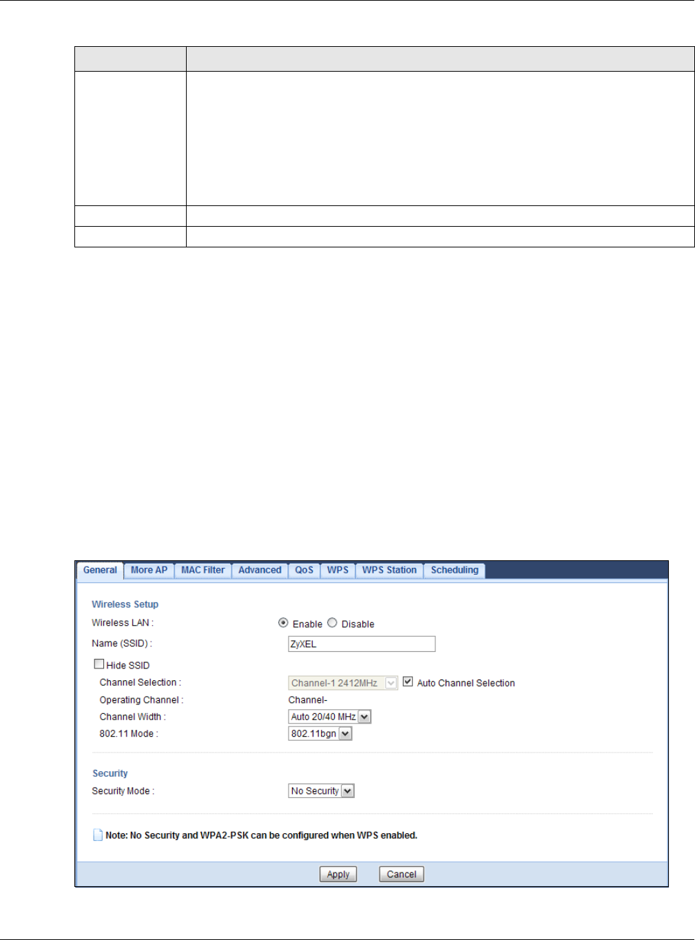
Chapter 9 Wireless LAN
EMG3425-Q10A User’s Guide
75
See the rest of this chapter for information on the other labels in this screen.
9.3 Wireless Security
The screen varies depending on what you select in the Se curit y M ode field.
9.3.1 No Security
Select N o Se cur ity to allow wireless clients to communicate with the access points without any
data encryption.
Note: If you do not enable any wireless security on your EMG3425-Q10A, your network is
accessible to any wireless networking device that is within range.
Figure 34 Network > Wireless LAN 2.4G/5G > General: No Security
Security Mode Select St a t ic W EP, W PA- PSK, W PA, W PA2 - PSK or W PA2 to add security on this
wireless network. The wireless clients which want to associate to this network must have
same wireless security settings as this device. After you select to use a security,
additional options appears in this screen. See Section 9.3 on page 75 for detailed
information on different security modes. Or you can select N o Se cur it y to allow any
client to associate this network without authentication.
Note: If the WPS function is enabled (default), only No Security and WPA2-PSK are
available in this field.
Apply Click Apply to save your changes back to the EMG3425-Q10A.
Cancel Click Cancel to reload the previous configuration for this screen.
Table 19 Network > Wireless LAN 2.4G/5G > General (continued)
LABEL DESCRIPTION
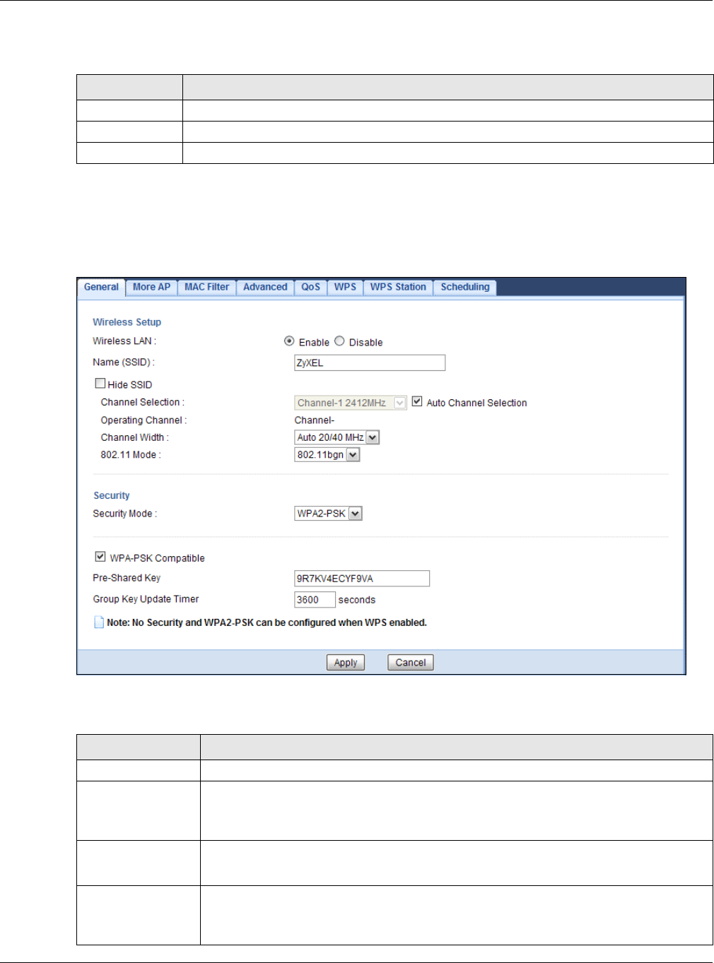
Chapter 9 Wireless LAN
EMG3425-Q10A User’s Guide
76
The following table describes the labels in this screen.
9.3.2 WPA-PSK/WPA2-PSK
Select W PA- PSK or W PA2 - PSK from the Securit y M ode list.
Figure 35 Network > Wireless LAN 2.4G/5G > General: WPA-PSK/WPA2-PSK
The following table describes the labels in this screen.
Table 20 Network > Wireless LAN 2.4G/5G > General: No Security
LABEL DESCRIPTION
Security Mode Choose N o Secur it y from the drop-down list box.
Apply Click Apply to save your changes back to the EMG3425-Q10A.
Cancel Click Cancel to reload the previous configuration for this screen.
Table 21 Network > Wireless LAN 2.4G/5G > General: WPA-PSK/WPA2-PSK
LABEL DESCRIPTION
Security Mode Select W PA- PSK or W PA2 - PSK to enable data encryption.
WPA-PSK
Compatible
This field appears when you choose W PA2 - PSK as the Security Mode.
Check this field to allow wireless devices using W PA- PSK security mode to connect to
your EMG3425-Q10A.
Pre-Shared Key W PA- PSK/ W PA2 - PSK uses a simple common password for authentication.
Type a pre-shared key from 8 to 63 case-sensitive keyboard characters.
Group Key Update
Timer
The Gr oup Key Upda t e Tim e r is the rate at which the AP sends a new group key out to
all clients.
The default is 3 6 0 0 seconds (60 minutes).
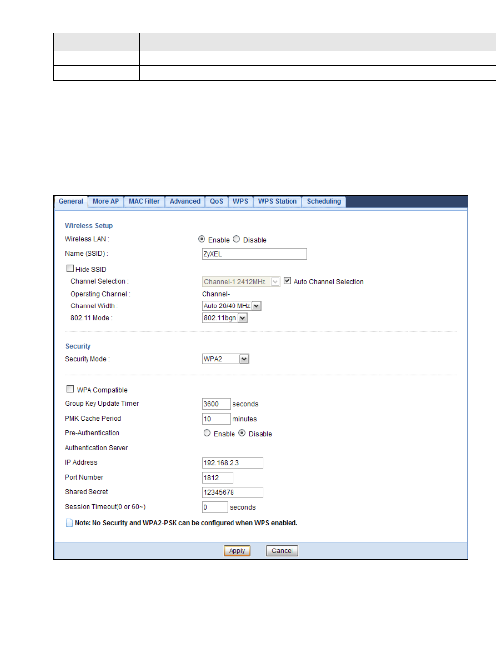
Chapter 9 Wireless LAN
EMG3425-Q10A User’s Guide
77
9.3.3 WPA/WPA2
Select W PA or W PA2 from the Se curit y Mode list.
Note: WPA or WPA2 is not available if you enable WPS before you configure WPA or WPA2
in the W ireless LAN 2 .4 G/ 5 G > Ge nera l screen.
Figure 36 Network > Wireless LAN 2.4G/5G > General: WPA/WPA2
Apply Click Apply to save your changes back to the EMG3425-Q10A.
Cancel Click Cancel to reload the previous configuration for this screen.
Table 21 Network > Wireless LAN 2.4G/5G > General: WPA-PSK/WPA2-PSK (continued)
LABEL DESCRIPTION

Chapter 9 Wireless LAN
EMG3425-Q10A User’s Guide
78
The following table describes the labels in this screen.
Table 22 Network > Wireless LAN 2.4G/5G > General: WPA/WPA2
LABEL DESCRIPTION
Security Mode Select W PA or W PA2 to enable data encryption.
WPA Compatible This check box is available only when you select W PA2 - PSK or W PA2 in the Secu rit y
Mode field.
Select the check box to have both WPA2 and WPA wireless clients be able to
communicate with the EMG3425-Q10A even when the EMG3425-Q10A is using WPA2-
PSK or WPA2.
Group Key Update
Timer
The Group Ke y Update Tim e r is the rate at which the AP (if using W PA- PSK/
W PA2 - PSK key management) or RADIUS server (if using W PA/ W PA2 key
management) sends a new group key out to all clients. The re-keying process is the
WPA/WPA2 equivalent of automatically changing the WEP key for an AP and all
stations in a WLAN on a periodic basis. Setting of the Group Ke y Update Tim e r is
also supported in W PA- PSK/ W PA2 - PSK mode.
PMK Cache Period This field is available only when you select W PA2 .
Specify how often wireless clients have to resend usernames and passwords in order
to stay connected. Enter a time interval between 10 and 999999 minutes.
Note: If wireless client authentication is done using a RADIUS server, the
reauthentication timer on the RADIUS server has priority.
Pre-Authentication This field is available only when you select W PA2 .
Pre-authentication enables fast roaming by allowing the wireless client (already
connecting to an AP) to perform IEEE 802.1x authentication with another AP before
connecting to it. Select Ena ble to turn on preauthentication in WAP2. Otherwise,
select Disable.
Authentication Server
IP Address Enter the IP address of the external authentication server in dotted decimal notation.
Port Number Enter the port number of the external authentication server.
You need not change this value unless your network administrator instructs you to do
so with additional information.
Shared Secret Enter a password (up to 127 alphanumeric characters) as the key to be shared
between the external authentication server and the EMG3425-Q10A.
The key must be the same on the external authentication server and your EMG3425-
Q10A. The key is not sent over the network.
Session Timeout The EMG3425-Q10A automatically disconnects a wireless client from the wireless and
wired networks after a period of inactivity. The wireless client needs to send the
username and password again before it can use the wireless and wired networks
again. Some wireless clients may prompt users for a username and password; other
clients may use saved login credentials. In either case, there is usually a short delay
while the wireless client logs in to the wireless network again.
Enter the time in seconds from 0 to 999999.
Apply Click Apply to save your changes back to the EMG3425-Q10A.
Cancel Click Cancel to reload the previous configuration for this screen.
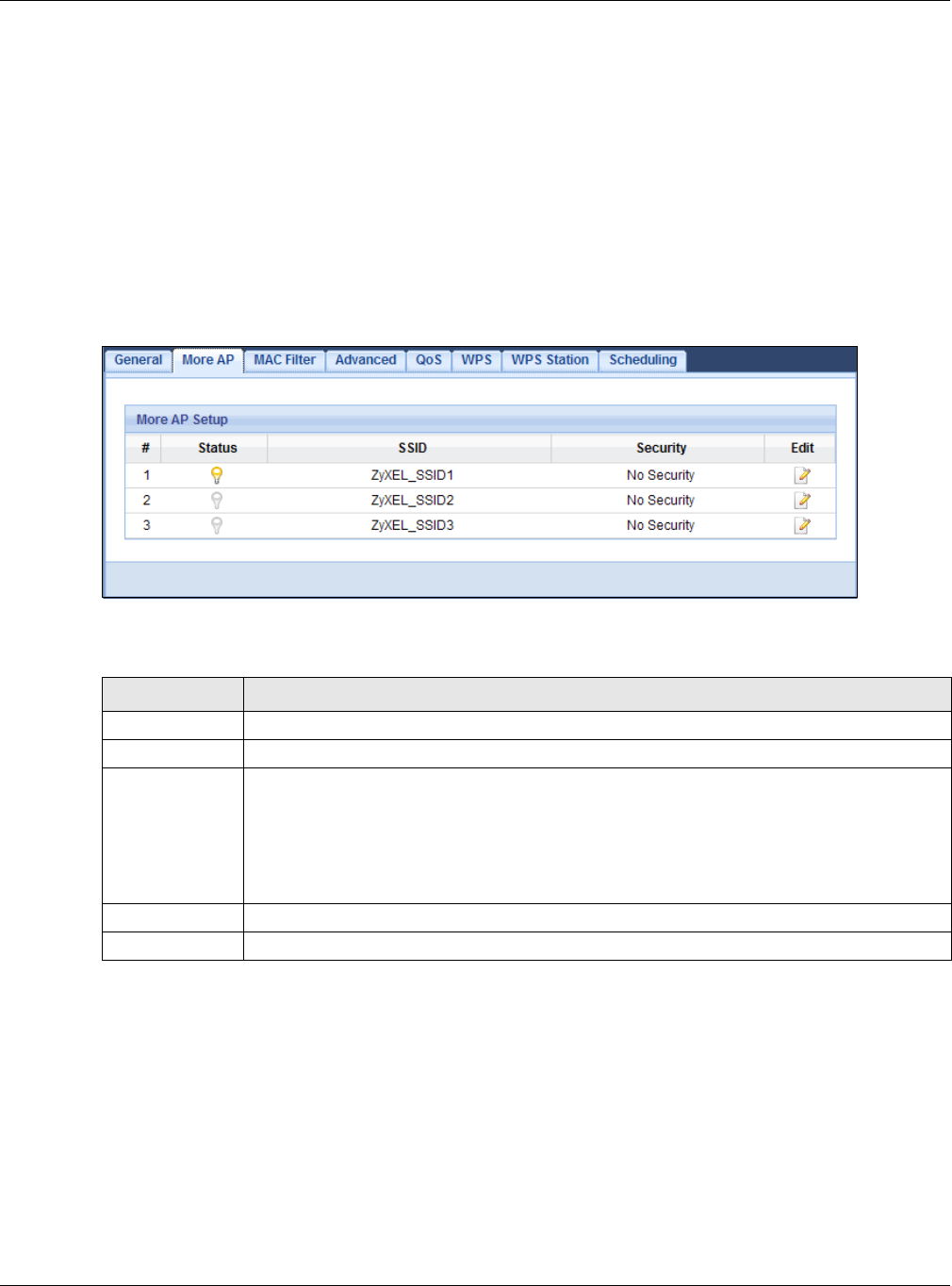
Chapter 9 Wireless LAN
EMG3425-Q10A User’s Guide
79
9.4 More AP Screen
This screen allows you to enable and configure multiple wireless networks and guest wireless
network settings on the EMG3425-Q10A.
You can configure up to four SSIDs to enable multiple BSSs (Basic Service Sets) on the EMG3425-
Q10A. This allows you to use one access point to provide several BSSs simultaneously. You can then
assign varying security types to different SSIDs. Wireless clients can use different SSIDs to
associate with the same access point.
Click N et w ork > W ireless LAN 2 .4 G/ 5 G > Mor e AP. The following screen displays.
Figure 37 Network > Wireless LAN 2.4G/5G > More AP
The following table describes the labels in this screen.
9.4.1 More AP Edit
Use this screen to edit an SSID profile. Click the Edit icon next to an SSID in the More AP screen.
The following screen displays.
Table 23 Network > Wireless LAN 2.4G/5G > More AP
LABEL DESCRIPTION
#This is the index number of each SSID profile.
Status This shows whether the SSID profile is active (a yellow bulb) or not (a gray bulb).
SSID An SSID profile is the set of parameters relating to one of the EMG3425-Q10A’s BSSs. The
SSID (Service Set IDentifier) identifies the Service Set with which a wireless device is
associated.
This field displays the name of the wireless profile on the network. When a wireless client
scans for an AP to associate with, this is the name that is broadcast and seen in the
wireless client utility.
Security This field indicates the security mode of the SSID profile.
Edit Click the Edit icon to configure the SSID profile.
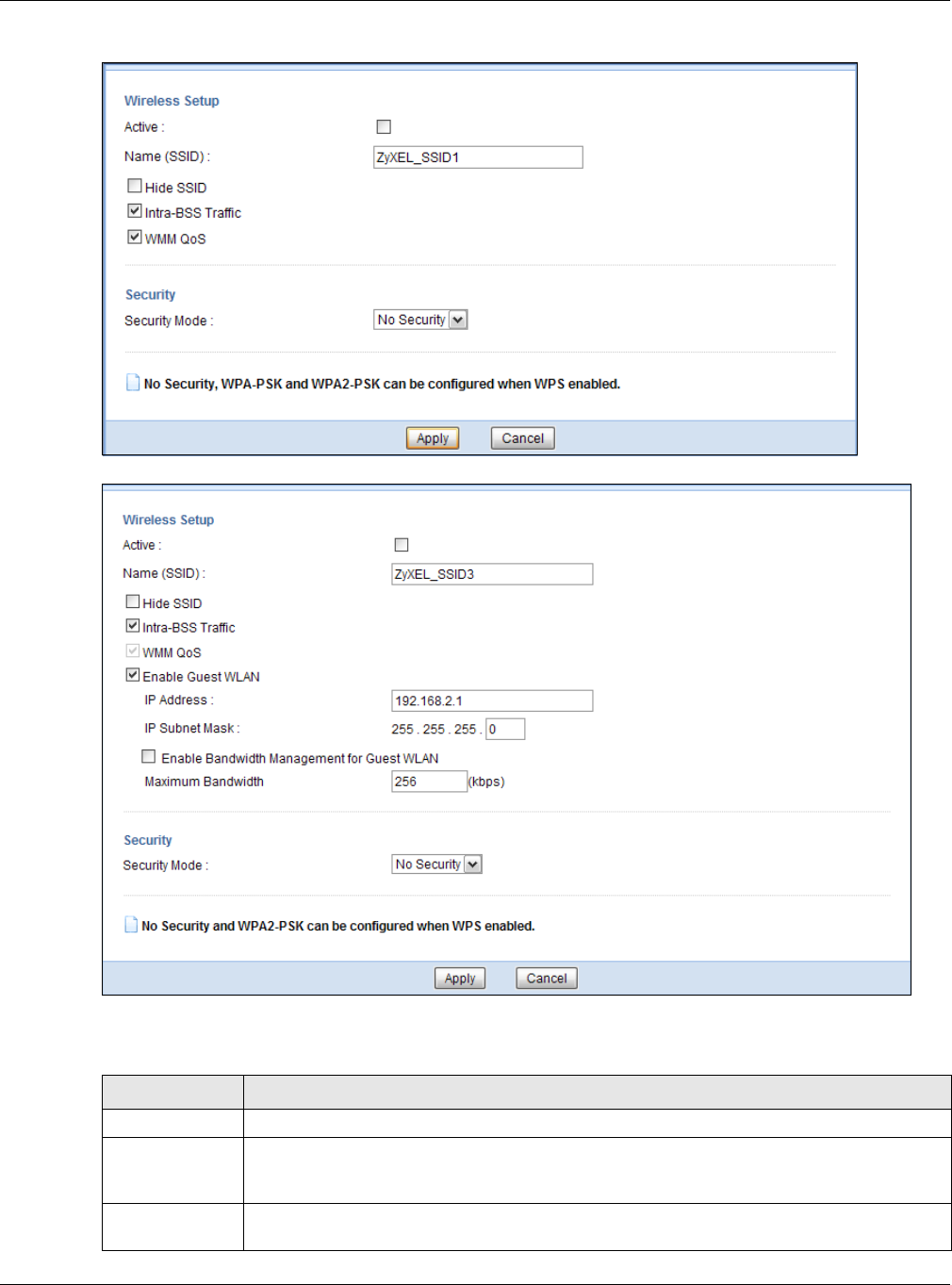
Chapter 9 Wireless LAN
EMG3425-Q10A User’s Guide
80
Figure 38 Network > Wireless LAN 2.4G/5G > More AP: Edit
Figure 39 Network > Wireless LAN 2.4G/5G > More AP: Edit (the last SSID)
The following table describes the labels in this screen.
Table 24 Network > Wireless LAN 2.4G/5G > More AP: Edit
LABEL DESCRIPTION
Active Select this to activate the SSID profile.
Name (SSID) The SSID (Service Set IDentity) identifies the Service Set with which a wireless client is
associated. Enter a descriptive name (up to 32 printable characters found on a typical
English language keyboard) for the wireless LAN.
Hide SSID Select this check box to hide the SSID in the outgoing beacon frame so a station cannot
obtain the SSID through scanning using a site survey tool.

Chapter 9 Wireless LAN
EMG3425-Q10A User’s Guide
81
9.5 MAC Filter Screen
The MAC filter screen allows you to configure the EMG3425-Q10A to give exclusive access to
devices (Allow ) or exclude devices from accessing the EMG3425-Q10A (De n y). Every Ethernet
device has a unique MAC (Media Access Control) address. The MAC address is assigned at the
factory and consists of six pairs of hexadecimal characters, for example, 00:A0:C5:00:00:02. You
need to know the MAC address of the devices to configure this screen.
To change your EMG3425-Q10A’s MAC filter settings, click N e t w or k > W ir e less LAN 2 .4 G/ 5 G >
MAC Filt e r. The screen appears as shown.
Intra-BSS Traffic A Basic Service Set (BSS) exists when all communications between wireless clients or
between a wireless client and a wired network client go through one access point (AP).
Intra-BSS traffic is traffic between wireless clients in the BSS. When Intra-BSS is enabled,
wireless clients can access the wired network and communicate with each other. When
Intra-BSS is disabled, wireless clients can still access the wired network but cannot
communicate with each other.
WMM QoS Check this to have the EMG3425-Q10A automatically give a service a priority level
according to the ToS value in the IP header of packets it sends.
WMM QoS (Wifi MultiMedia Quality of Service) gives high priority to voice and video, which
makes them run more smoothly.
Enable Guest
WLAN
Select the check box to activate guest wireless LAN. This is available only for the last SSID
on the EMG3425-Q10A.
IP Address Type an IP address for the devices on the Guest WLAN using this as the gateway IP
address.
IP Subnet
Mask Type the subnet mask for the guest wireless LAN.
Enable
Bandwidth
Management
for Guest
WLAN
Select this to turn on bandwidth management for the Guest WLAN network.
Maximum
Bandwidth Enter a number to specify maximum bandwidth the Guest WLAN network can use.
Security Mode Select Static W EP, W PA- PSK, W PA, W PA2 - PSK or W PA2 to add security on this
wireless network. The wireless clients which want to associate to this network must have
same wireless security settings as this device. After you select to use a security, additional
options appears in this screen. See Section 9.3 on page 75 for detailed information on
different security modes. Or you can select N o Se cur it y to allow any client to associate
this network without authentication.
Note: If the WPS function is enabled (default), only No Security and WPA2-PSK are
available in this field.
Apply Click Apply to save your changes back to the EMG3425-Q10A.
Cancel Click Cancel to reload the previous configuration for this screen.
Table 24 Network > Wireless LAN 2.4G/5G > More AP: Edit (continued)
LABEL DESCRIPTION
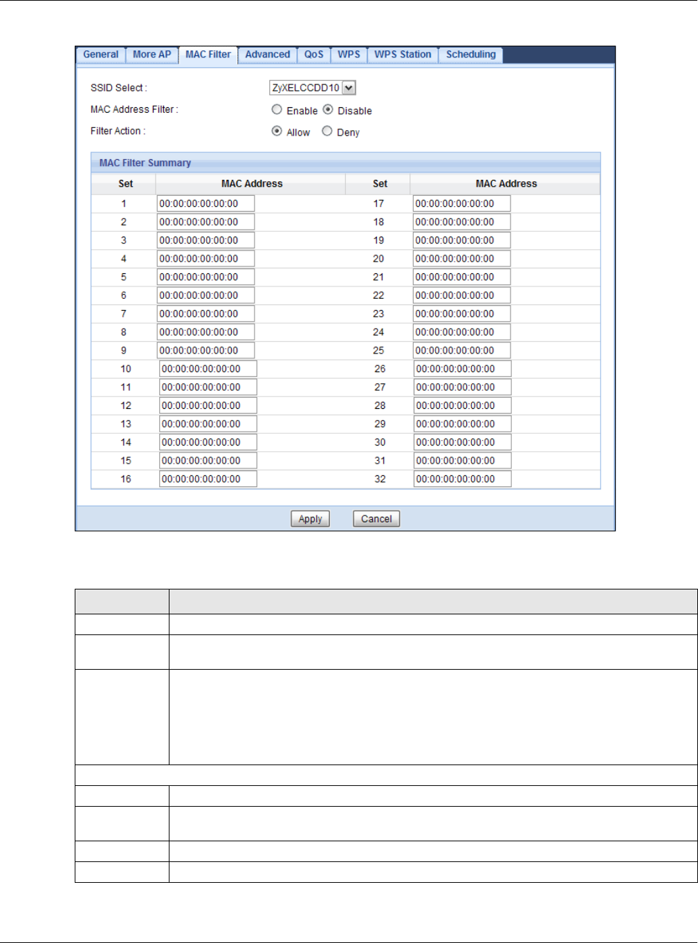
Chapter 9 Wireless LAN
EMG3425-Q10A User’s Guide
82
Figure 40 Network > Wireless LAN 2.4G/5G > MAC Filter
The following table describes the labels in this menu.
Table 25 Network > Wireless LAN 2.4G/5G > MAC Filter
LABEL DESCRIPTION
SSID Select Select the SSID for which you want to configure MAC filtering.
MAC Address
Filter
Select to turn on (Enable) or off (Disa ble) MAC address filtering.
Filter Action Define the filter action for the list of MAC addresses in the M AC Filt e r Sum m a ry table.
Select Allow to permit access to the EMG3425-Q10A, MAC addresses not listed will be
denied access to the EMG3425-Q10A.
Select De ny to block access to the EMG3425-Q10A, MAC addresses not listed will be allowed
to access the EMG3425-Q10A.
MAC Filter Summary
Set This is the index number of the MAC address.
MAC Address Enter the MAC address of the wireless station that are allowed or denied access to the
EMG3425-Q10A.
Apply Click Apply to save your changes back to the EMG3425-Q10A.
Cancel Click Cancel to reload the previous configuration for this screen.
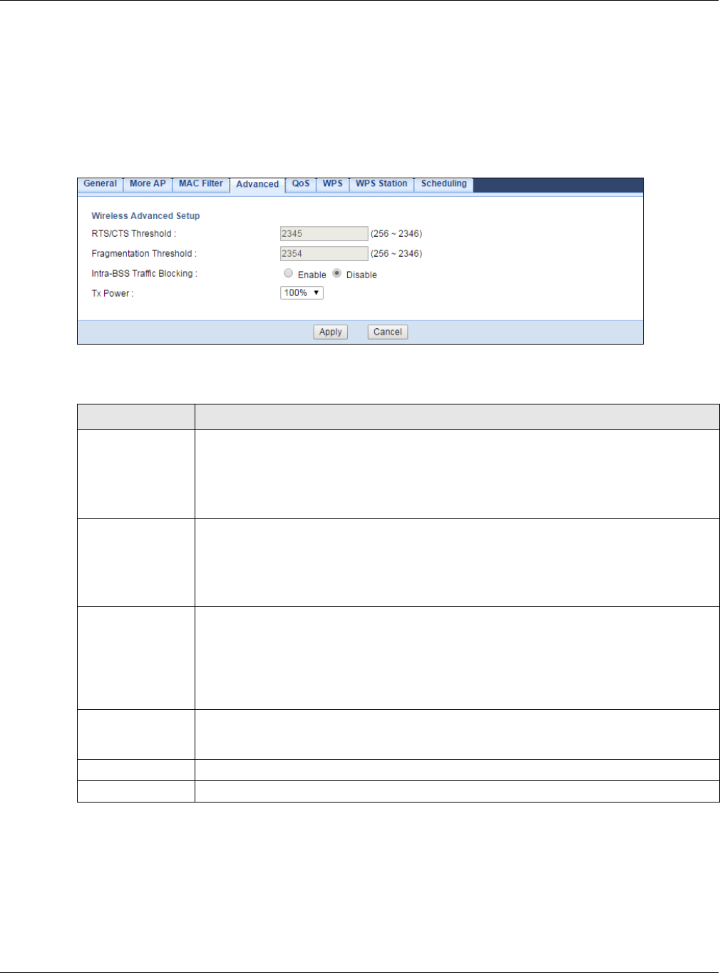
Chapter 9 Wireless LAN
EMG3425-Q10A User’s Guide
83
9.6 Wireless LAN Advanced Screen
Use this screen to allow wireless advanced features, such as the output power, RTS/CTS Threshold
settings.
Click N e t w o rk > W ir e less LAN 2 .4 G/ 5 G > Adva nce d. The screen appears as shown.
Figure 41 Network > Wireless LAN 2.4G/5G > Advanced
The following table describes the labels in this screen.
9.7 Quality of Service (QoS) Screen
The QoS screen allows you to automatically give a service (such as VoIP and video) a priority level.
Click N e t w o rk > W ir e less LAN 2 .4 G/ 5 G > QoS. The following screen appears.
Table 26 Network > Wireless LAN 2.4G/5G > Advanced
LABEL DESCRIPTION
RTS/CTS
Threshold
Data with its frame size larger than this value will perform the RTS (Request To Send)/
CTS (Clear To Send) handshake.
This field is not configurable and the EMG3425-Q10A automatically changes to use the
maximum value if you select 8 0 2 .1 1 a / a n, 8 0 2 .1 1 a/ a n/ ac, 8 0 2 .1 1 n, 8 0 2 .1 1 gn or
8 0 2 .1 1 bgn in the W ir e le ss LAN 2 .4 G/ 5 G > Gene ral screen.
Fragmentation
Threshold
The threshold (number of bytes) for the fragmentation boundary for directed messages.
It is the maximum data fragment size that can be sent.
This field is not configurable and the EMG3425-Q10A automatically changes to use the
maximum value if you select 8 0 2 .1 1 a / a n, 8 0 2 .1 1 a/ a n/ ac, 8 0 2 .1 1 n, 8 0 2 .1 1 gn or
8 0 2 .1 1 bgn in the W ir e le ss LAN 2 .4 G/ 5 G > Gene ral screen.
Intra-BSS Traffic
Blocking
A Basic Service Set (BSS) exists when all communications between wireless clients or
between a wireless client and a wired network client go through one access point (AP).
Intra-BSS traffic is traffic between wireless clients in the BSS. When Intra-BSS is
enabled, wireless clients can access the wired network and communicate with each other.
When Intra-BSS is disabled, wireless clients can still access the wired network but cannot
communicate with each other.
Tx Power Set the output power of the EMG3425-Q10A in this field. If there is a high density of APs
in an area, decrease the output power of the EMG3425-Q10A to reduce interference with
other APs. Select one of the following 1 0 0 % , 9 0 % , 7 5 % , 5 0 % , 2 5 % or 1 0 % .
Apply Click Apply to save your changes back to the EMG3425-Q10A.
Cancel Click Cancel to reload the previous configuration for this screen.
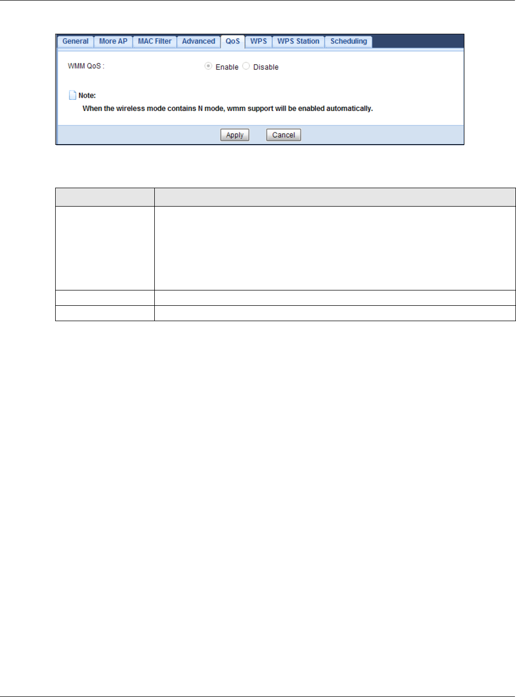
Chapter 9 Wireless LAN
EMG3425-Q10A User’s Guide
84
Figure 42 Network > Wireless LAN 2.4G/5G > QoS
The following table describes the labels in this screen.
9.8 WPS Screen
Use this screen to enable/disable WPS, view or generate a new PIN number and check current WPS
status. To open this screen, click N et w ork > W ir e less LAN 2 .4 G/ 5 G > W PS.
Note: With WPS, wireless clients can only connect to the wireless network using the first
SSID on the EMG3425-Q10A.
Table 27 Network > Wireless LAN 2.4G/5G > QoS
LABEL DESCRIPTION
WMM QoS Select Enable to have the EMG3425-Q10A automatically give a service a priority level
according to the ToS value in the IP header of packets it sends. WMM QoS (Wifi
MultiMedia Quality of Service) gives high priority to voice and video, which makes
them run more smoothly.
This field is not configurable and the EMG3425-Q10A automatically enables WMM QoS
if you select 8 0 2 .1 1 n, 8 0 2 .1 1 a n, 8 0 2 .1 1 gn or 8 0 2 .1 1 bgn in the W ir eless LAN
2 4 G/ 5 G > Ge neral screen.
Apply Click Apply to save your changes to the EMG3425-Q10A.
Cancel Click Cancel to reload the previous configuration for this screen.
Chapter 9 Wireless LAN
EMG3425-Q10A User’s Guide
85
Figure 43 Network > Wireless LAN 2.4G/5G > WPS
The following table describes the labels in this screen.
Table 28 Network > Wireless LAN 2.4G/5G > WPS
LABEL DESCRIPTION
WPS Setup
WPS Select En able to turn on the WPS feature. Otherwise, select Disa ble.
PIN Code Select En able and click Apply to allow the PIN Configuration method. If you select
Disable , you cannot create a new PIN number.
PIN Number This is the WPS PIN (Personal Identification Number) of the EMG3425-Q10A. Enter this
PIN in the configuration utility of the device you want to connect to the EMG3425-Q10A
using WPS.
The PIN is not necessary when you use WPS push-button method.
Click Gen e r at e to generate a new PIN number.
WPS Status
Status This displays Configured when the EMG3425-Q10A has connected to a wireless
network using WPS or when W PS Enable is selected and wireless or wireless security
settings have been changed. The current wireless and wireless security settings also
appear in the screen.
This displays Unconfigur e d if WPS is disabled and there are no wireless or wireless
security changes on the EMG3425-Q10A or you click Release Con figu r at ion to remove
the configured wireless and wireless security settings.
Release
Configuration
This button is only available when the WPS status displays Configur ed.
Click this button to remove all configured wireless and wireless security settings for WPS
connections on the EMG3425-Q10A.
802.11 Mode This is the 802.11 mode used. Only compliant WLAN devices can associate with the
EMG3425-Q10A.
SSID This is the name of the wireless network (the EMG3425-Q10A’s first SSID).
Security This is the type of wireless security employed by the network.
Chapter 9 Wireless LAN
EMG3425-Q10A User’s Guide
86
9.9 WPS Station Screen
Use this screen when you want to add a wireless station using WPS. To open this screen, click
N e t w o rk > W ireless LAN 2 .4 G/ 5 G > W PS St a t ion tab.
Note: After you click Push Button on this screen, you have to press a similar button in
the wireless station utility within 2 minutes. To add the second wireless station, you
have to press these buttons on both device and the wireless station again after the
first 2 minutes.
Figure 44 Network > Wireless LAN 2.4G/5G > WPS Station
The following table describes the labels in this screen.
9.10 Scheduling Screen
Use this screen to set the times your wireless LAN is turned on and off. Wireless LAN scheduling is
disabled by default. The wireless LAN can be scheduled to turn on or off on certain days and at
certain times. To open this screen, click N e t w or k > W irele ss LAN 2 .4 G/ 5 G > Sch e dulin g tab.
Apply Click Apply to save your changes back to the EMG3425-Q10A.
Cancel Click Cancel to reload the previous configuration for this screen.
Table 28 Network > Wireless LAN 2.4G/5G > WPS (continued)
LABEL DESCRIPTION
Table 29 Network > Wireless LAN 2.4G/5G > WPS Station
LABEL DESCRIPTION
Push Button Use this button when you use the PBC (Push Button Configuration) method to configure
wireless stations’s wireless settings.
Click this to start WPS-aware wireless station scanning and the wireless security
information synchronization.
Or input station’s
PIN number
Use this button when you use the PIN Configuration method to configure wireless
station’s wireless settings.
Type the same PIN number generated in the wireless station’s utility. Then click St a r t to
associate to each other and perform the wireless security information synchronization.
Chapter 9 Wireless LAN
EMG3425-Q10A User’s Guide
87
Figure 45 Network > Wireless LAN 2.4G/5G > Scheduling
The following table describes the labels in this screen.
Table 30 Network > Wireless LAN 2.4G/5G > Scheduling
LABEL DESCRIPTION
Wireless LAN Scheduling
Wireless LAN
Scheduling
Select Enable to activate the wireless LAN scheduling feature. Select Disa ble to turn it
off.
Scheduling
WLAN Status Select On or Off to specify whether the Wireless LAN is turned on or off. This field works
in conjunction with the Day and For t he follow ing tim es fields.
Day Select Everyday or the specific days to turn the Wireless LAN on or off. If you select
Everyday you can not select any specific days. This field works in conjunction with the
For t he follow ing tim es field.
For the following
times (24-Hour
Format)
Select a begin time using the first set of hou r and minute (m in) drop down boxes and
select an end time using the second set of hour and minute (m in ) drop down boxes. If
you have chosen On earlier for the WLAN Status the Wireless LAN will turn on between
the two times you enter in these fields. If you have chosen Off earlier for the WLAN
Status the Wireless LAN will turn off between the two times you enter in these fields.
Apply Click Apply to save your changes back to the EMG3425-Q10A.
Cancel Click Cancel to reload the previous configuration for this screen.
EMG3425-Q10A User’s Guide
88
CHAPTER 10
LAN
10.1 Overview
This chapter describes how to configure LAN settings.
A Local Area Network (LAN) is a shared communication system to which many computers are
attached. A LAN is a computer network limited to the immediate area, usually the same building or
floor of a building.
Figure 46 LAN Example
The LAN screens can help you configure a manage IP address, and partition your physical network
into logical networks.
10.2 What You Can Do
•Use the I P screen to change the IP address for your EMG3425-Q10A (Section 10.4 on page 90).
•Use the I P Alias screen to have the EMG3425-Q10A apply IP alias to create LAN subnets
(Section 10.5 on page 90).
•Use the I Pv6 LAN screen to configure the IPv6 address for your EMG3425-Q10A on the LAN
(Section 10.6 on page 91).
•Use the I GM P Snooping screen to enable IGMP Snooping and configure IGMP modes. (Section
10.7 on page 92).
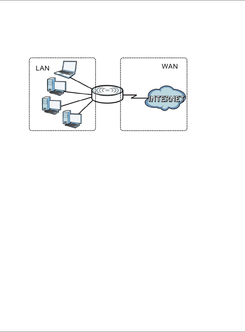
Chapter 10 LAN
EMG3425-Q10A User’s Guide
89
10.3 What You Need To Know
The actual physical connection determines whether the EMG3425-Q10A ports are LAN or WAN
ports. There are two separate IP networks, one inside the LAN network and the other outside the
WAN network as shown next.
Figure 47 LAN and WAN IP Addresses
The LAN parameters of the EMG3425-Q10A are preset in the factory with the following values:
• IP address of 192.168.1.1 with subnet mask of 255.255.255.0 (24 bits)
• DHCP server enabled with 32 client IP addresses starting from 192.168.1.33.
These parameters should work for the majority of installations. If your ISP gives you explicit DNS
server address(es), read the embedded Web Configurator help regarding what fields need to be
configured.
10.3.1 IP Pool Setup
The EMG3425-Q10A is pre-configured with a pool of 32 IP addresses starting from 192.168.1.33 to
192.168.1.64. This configuration leaves 31 IP addresses (excluding the EMG3425-Q10A itself) in
the lower range (192.168.1.2 to 192.168.1.32) for other server computers, for instance, servers for
mail, FTP, TFTP, web, etc., that you may have.
10.3.2 LAN TCP/IP
The EMG3425-Q10A has built-in DHCP server capability that assigns IP addresses and DNS servers
to systems that support DHCP client capability.
10.3.3 IP Alias
IP alias allows you to partition a physical network into different logical networks over the same
Ethernet interface. The EMG3425-Q10A supports three logical LAN interfaces via its single physical
Ethernet interface with the EMG3425-Q10A itself as the gateway for each LAN network.
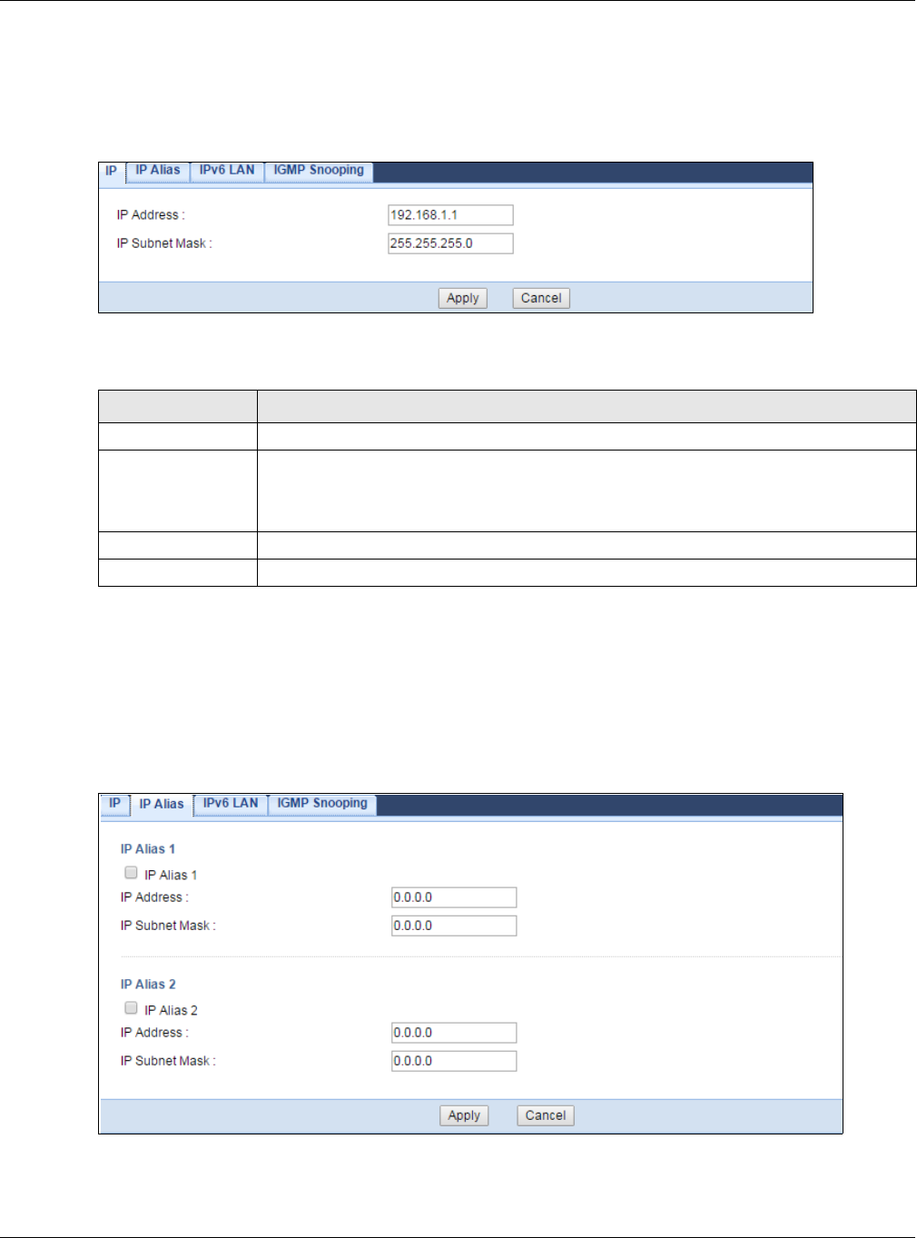
Chapter 10 LAN
EMG3425-Q10A User’s Guide
90
10.4 LAN IP Screen
Use this screen to change the IP address for your EMG3425-Q10A. Click Net w or k > LAN > I P.
Figure 48 Network > LAN > IP
The following table describes the labels in this screen.
10.5 IP Alias Screen
Use this screen to have the EMG3425-Q10A apply IP alias to create LAN subnets. Click LAN > I P
Alias.
Figure 49 Network > LAN > IP Alias
Table 31 Network > LAN > IP
LABEL DESCRIPTION
IP Address Type the IP address of your EMG3425-Q10A in dotted decimal notation.
IP Subnet Mask The subnet mask specifies the network number portion of an IP address. Your
EMG3425-Q10A will automatically calculate the subnet mask based on the IP address
that you assign. Unless you are implementing subnetting, use the subnet mask
computed by the EMG3425-Q10A.
Apply Click Apply to save your changes back to the EMG3425-Q10A.
Cancel Click Cancel to begin configuring this screen afresh.
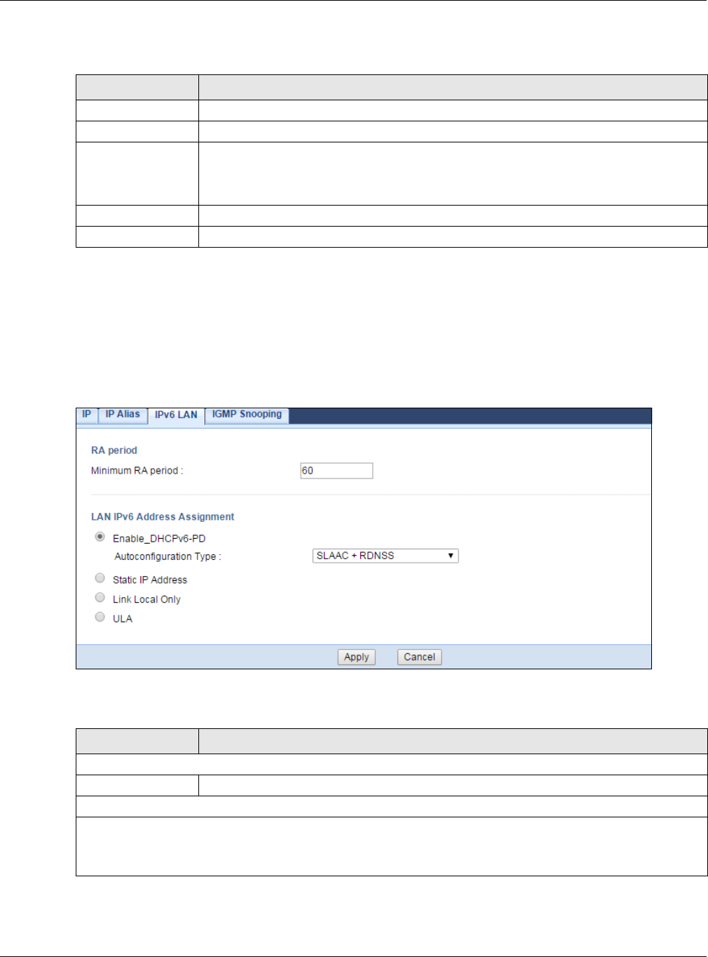
Chapter 10 LAN
EMG3425-Q10A User’s Guide
91
The following table describes the labels in this screen.
10.6 IPv6 LAN Screen
Use this screen to configure the IPv6 address for your EMG3425-Q10A on the LAN. Click Net w ork
> LAN > I Pv6 LAN .
Figure 50 Network > LAN > IPv6 LAN
The following table describes the labels on this screen.
Table 32 Network > LAN > IP Alias
LABEL DESCRIPTION
IP Alias 1, 2 Check this to enable IP alias to configure another LAN network for the EMG3425-Q10A.
IP Address Type the IP alias address of your EMG3425-Q10A in dotted decimal notation.
IP Subnet Mask The subnet mask specifies the network number portion of an IP address. Your
EMG3425-Q10A will automatically calculate the subnet mask based on the IP address
that you assign. Unless you are implementing subnetting, use the subnet mask
computed by the EMG3425-Q10A.
Apply Click Apply to save your changes back to the EMG3425-Q10A.
Cancel Click Can cel to begin configuring this screen afresh.
Table 33 Network > LAN > IPv6 LAN
LABEL DESCRIPTION
RA period
Minimum RA period Enter the minimum time in seconds between router advertisement messages.
LAN IPv6 Address Assignment
Enable DHCPv6-PD
Select this option to use DHCPv6 prefix delegation. The EMG3425-Q10A will obtain an IPv6 prefix from the ISP
or a connected uplink router for the LAN.
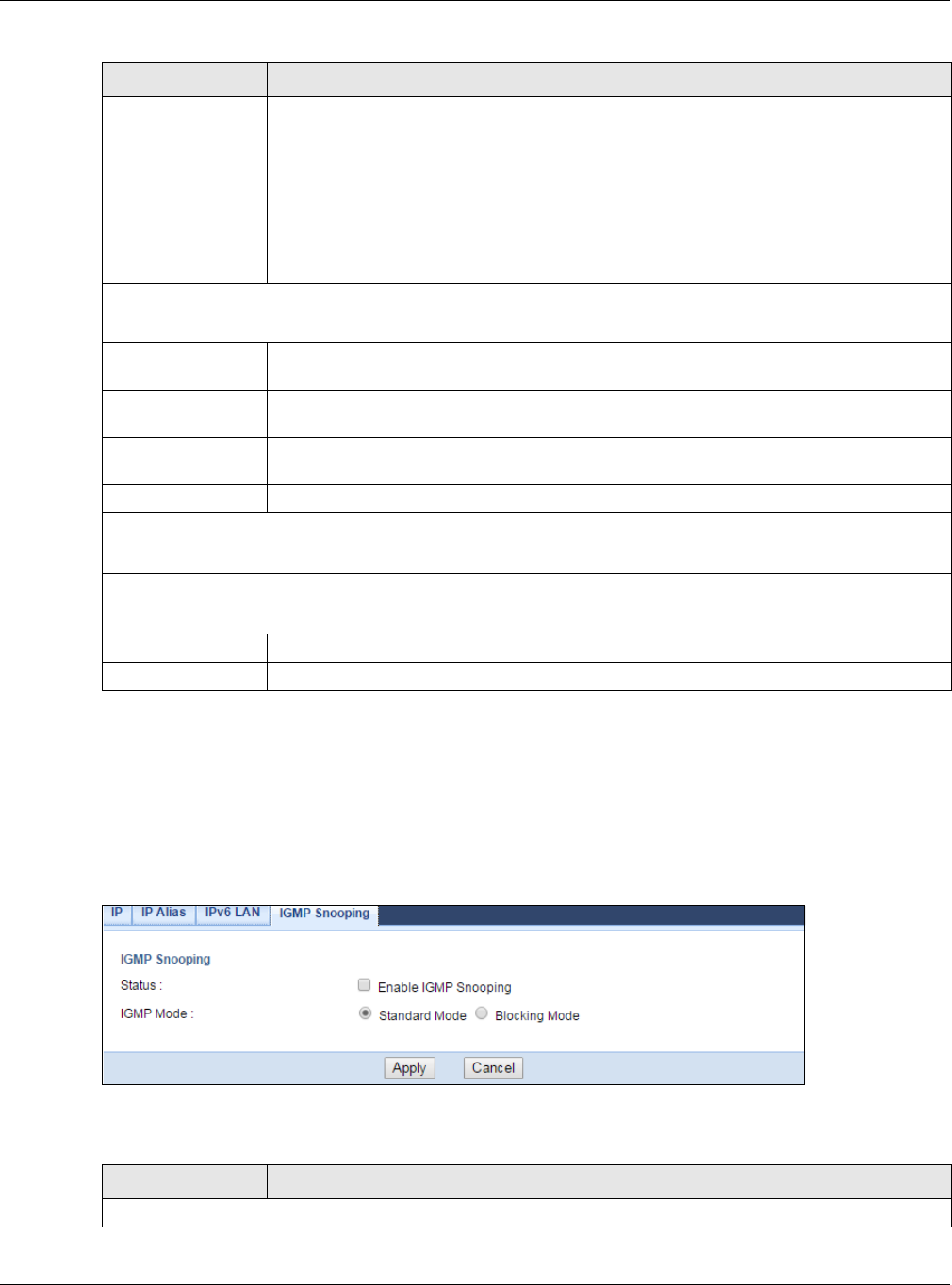
Chapter 10 LAN
EMG3425-Q10A User’s Guide
92
10.7 IGMP Snooping Screen
Use this screen to enable IGMP Snooping and configure IGMP mode. Click Net w ork > LAN >
I GM P Sn oopin g.
Figure 51 Network > LAN > IGMP Snooping
The following table describes the labels on this screen.
Autoconfiguration
Type
Select SLAAC + RD N SS to enable IPv6 stateless auto-configuration on this interface.
The interface will generate an IPv6 IP address itself from a prefix obtained from an IPv6
router in the network.
Select SLAAC + St a t eless D H CPv6 to enable IPv6 stateless auto-configuration on this
interface. The interface will get an IPv6 address from an IPv6 router and the DHCP
server. The IP address information gets through DHCPv6.
Select Stateful DHCPv6 to allow a DHCP server to assign and pass IPv6 network
addresses, prefixes and other configuration information to DHCP clients.
Static IP Address
Select this option to manually enter an IPv6 address if you want to use a static IP address.
LAN IPv6 Address Enter the LAN IPv6 address you want to assign to your EMG3425-Q10A in hexadecimal
notation.
LAN IPv6 Prefix
Length (48~64)
Enter the 48 to 64 address prefix length to specify in an IPv6 address compose the
network address.
Prefix Preferred
Lifetime
Enter the preferred lifetime for the prefix.
Prefix Valid Lifetime Enter the valid lifetime for the prefix.
Link Local Only
Select this option to only use the link local address on the EMG3425-Q10A interfaces in the LAN.
ULA
Select this option to identify a unique local address of the EMG3425-Q10A in the LAN.
Apply Click Apply to save your changes with the EMG3425-Q10A.
Cancel Click Cancel to begin configuring this screen afresh.
Table 33 Network > LAN > IPv6 LAN (continued)
LABEL DESCRIPTION
Table 34 Network > LAN > IGMP Snooping
LABEL DESCRIPTION
IGMP Snooping

Chapter 10 LAN
EMG3425-Q10A User’s Guide
93
Status Select this option to activate IGMP snooping. This allows the EMG3425-Q10A to
passively learn multicast group.
IGMP Mode Select St a n dard M ode to have the EMG3425-Q10A forward multicast packets to a port
that joins the multicast group and broadcast unknown multicast packets from the WAN
to all LAN ports.
Select Blocking Mode to have the EMG3425-Q10A block all unknown multicast packets
from the WAN.
Apply Click Apply to save your changes with the EMG3425-Q10A.
Cancel Click Cancel to begin configuring this screen afresh.
Table 34 Network > LAN > IGMP Snooping (continued)
LABEL DESCRIPTION

EMG3425-Q10A User’s Guide
94
CHAPTER 11
DHCP Server
11.1 Overview
DHCP (Dynamic Host Configuration Protocol, RFC 2131 and RFC 2132) allows individual clients to
obtain TCP/IP configuration at start-up from a server. You can configure the EMG3425-Q10A’s LAN
as a DHCP server or disable it. When configured as a server, the EMG3425-Q10A provides the TCP/
IP configuration for the clients. If DHCP service is disabled, you must have another DHCP server on
your LAN, or else the computer must be manually configured.
11.1.1 What You Can Do
•Use the Ge n e r a l screen to enable the DHCP server (Section 11.2 on page 94).
•Use the Adva nced screen to assign IP addresses on the LAN to specific individual computers
based on their MAC Addresses (Section 11.3 on page 95).
•Use the Clie n t List screen to view the current DHCP client information (Section 11.4 on page
97).
11.1.2 What You Need To Know
The following terms and concepts may help as you read through this chapter.
MAC Addresses
Every Ethernet device has a unique MAC (Media Access Control) address. The MAC address is
assigned at the factory and consists of six pairs of hexadecimal characters, for example,
00:A0:C5:00:00:02. Find out the MAC addresses of your network devices if you intend to add them
to the DH CP Client List screen.
11.2 DHCP Server General Screen
Use this screen to enable the DHCP server. Click N e t w o rk > DHCP Ser ver. The following screen
displays.
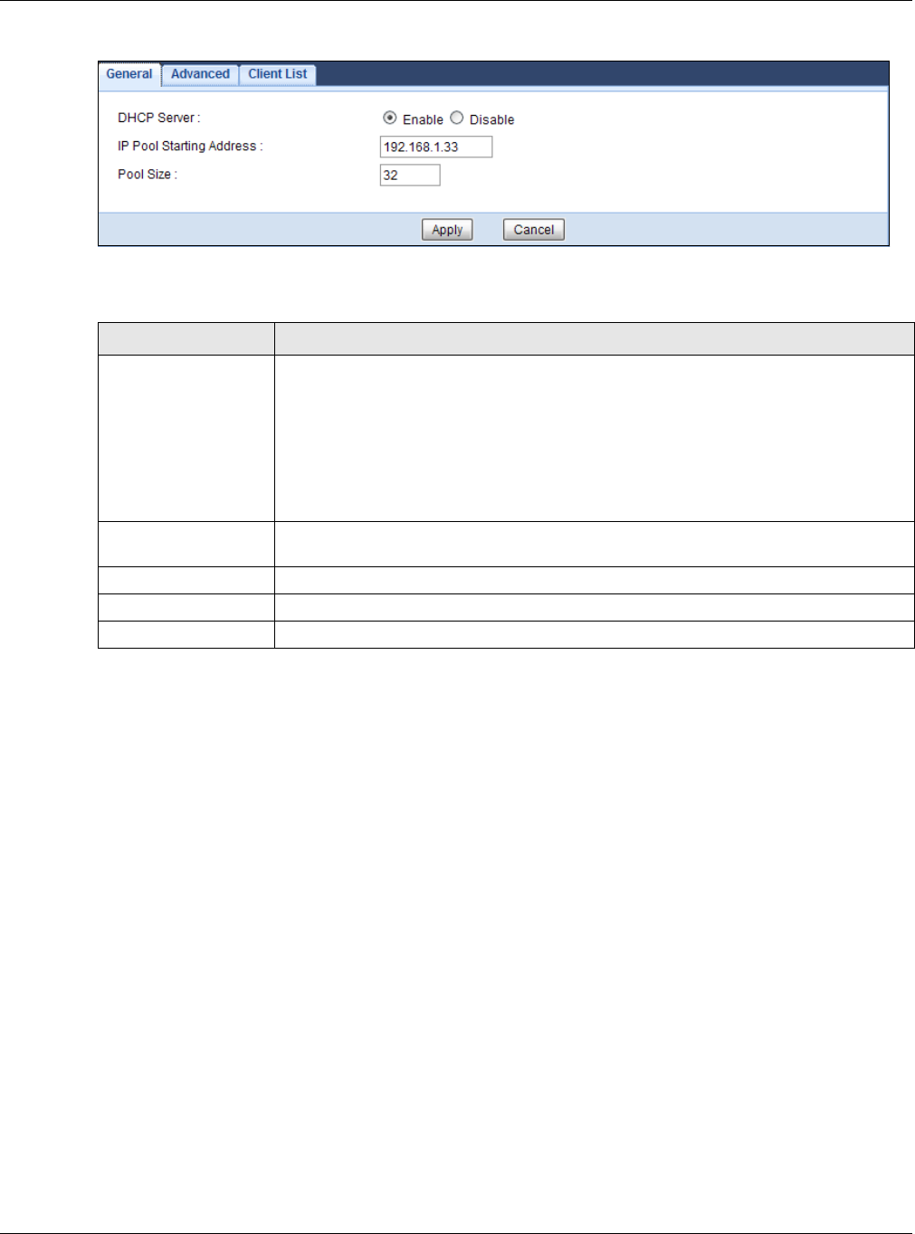
Chapter 11 DHCP Server
EMG3425-Q10A User’s Guide
95
Figure 52 Network > DHCP Server > General
The following table describes the labels in this screen.
11.3 DHCP Server Advanced Screen
This screen allows you to assign IP addresses on the LAN to specific individual computers based on
their MAC addresses. You can also use this screen to configure the DNS server information that the
EMG3425-Q10A sends to the DHCP clients.
To change your EMG3425-Q10A’s static DHCP settings, click N e t w o r k > DHCP Server >
Advance d . The following screen displays.
Table 35 Network > DHCP Server > General
LABEL DESCRIPTION
DHCP Server Select Ena ble to activate DHCP for LAN.
DHCP (Dynamic Host Configuration Protocol, RFC 2131 and RFC 2132) allows
individual clients (computers) to obtain TCP/IP configuration at startup from a server.
Enable the DHCP server unless your ISP instructs you to do otherwise. Select Disa ble
to stop the EMG3425-Q10A acting as a DHCP server. When configured as a server, the
EMG3425-Q10A provides TCP/IP configuration for the clients. If not, DHCP service is
disabled and you must have another DHCP server on your LAN, or else the computers
must be manually configured. When set as a server, fill in the following four fields.
IP Pool Starting
Address
This field specifies the first of the contiguous addresses in the IP address pool for LAN.
Pool Size This field specifies the size, or count of the IP address pool for LAN.
Apply Click Apply to save your changes back to the EMG3425-Q10A.
Cancel Click Cancel to begin configuring this screen afresh.
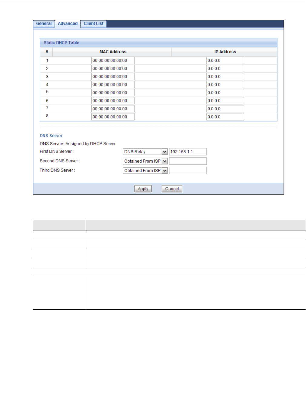
Chapter 11 DHCP Server
EMG3425-Q10A User’s Guide
96
Figure 53 Network > DHCP Server > Advanced
The following table describes the labels in this screen.
Table 36 Network > DHCP Server > Advanced
LABEL DESCRIPTION
Static DHCP Table
# This is the index number of the static IP table entry (row).
MAC Address Type the MAC address (with colons) of a computer on your LAN.
IP Address Type the LAN IP address of a computer on your LAN.
DNS Server
DNS Servers
Assigned by DHCP
Server
The EMG3425-Q10A passes a DNS (Domain Name System) server IP address (in the
order you specify here) to the DHCP clients. The EMG3425-Q10A only passes this
information to the LAN DHCP clients when you enable DHCP Ser ver. When you disable
DHCP Se rver, DHCP service is disabled and you must have another DHCP sever on your
LAN, or else the computers must have their DNS server addresses manually configured.
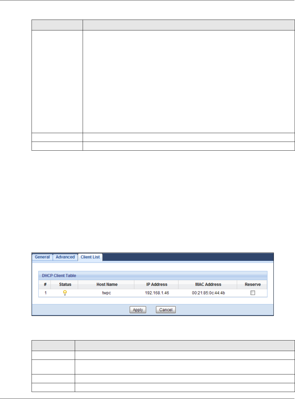
Chapter 11 DHCP Server
EMG3425-Q10A User’s Guide
97
11.4 DHCP Client List Screen
The DHCP table shows current DHCP client information (including IP Address, Host Name and MAC
Address) of network clients using the EMG3425-Q10A’s DHCP servers.
Configure this screen to always assign an IP address to a MAC address (and host name). Click
N e tw ork > DHCP Server > Clie n t List .
Note: You can also view a read-only client list by clicking Monitor > DH CP Server.
Figure 54 Network > DHCP Server > Client List
The following table describes the labels in this screen.
First DNS Server
Second DNS Server
Third DNS Server
Select Obtained From I SP if your ISP dynamically assigns DNS server information
(and the EMG3425-Q10A's WAN IP address). The field to the right displays the (read-
only) DNS server IP address that the ISP assigns.
Select Use r- D efine d if you have the IP address of a DNS server. Enter the DNS server's
IP address in the field to the right.
Select DNS Relay to have the EMG3425-Q10A act as a DNS proxy. The EMG3425-
Q10A's LAN IP address displays in the field to the right (read-only). The EMG3425-Q10A
tells the DHCP clients on the LAN that the EMG3425-Q10A itself is the DNS server. When
a computer on the LAN sends a DNS query to the EMG3425-Q10A, the EMG3425-Q10A
forwards the query to the EMG3425-Q10A's system DNS server (configured in the W AN
screen) and relays the response back to the computer. You can only select DN S Relay
for one of the three servers; if you select DNS Re la y for a second or third DNS server,
that choice changes to N one after you click Apply.
Select N one if you do not want to configure DNS servers. If you do not configure a DNS
server, you must know the IP address of a computer in order to access it.
Apply Click Apply to save your changes back to the EMG3425-Q10A.
Cancel Click Cancel to begin configuring this screen afresh.
Table 36 Network > DHCP Server > Advanced (continued)
LABEL DESCRIPTION
Table 37 Network > DHCP Server > Client List
LABEL DESCRIPTION
# This is the index number of the host computer.
Status This field displays whether the connection to the host computer is up (a yellow bulb) or
down (a gray bulb).
Host Name This field displays the computer host name.
IP Address This field displays the IP address relative to the # field listed above.

Chapter 11 DHCP Server
EMG3425-Q10A User’s Guide
98
MAC Address This field shows the MAC address of the computer with the name in the Host Nam e field.
Every Ethernet device has a unique MAC (Media Access Control) address which uniquely
identifies a device. The MAC address is assigned at the factory and consists of six pairs of
hexadecimal characters, for example, 00:A0:C5:00:00:02.
Reserve Select this if you want to reserve the IP address for this specific MAC address.
Apply Click Apply to save your changes back to the EMG3425-Q10A.
Cancel Click Can cel to reload the previous configuration for this screen.
Table 37 Network > DHCP Server > Client List (continued)
LABEL DESCRIPTION
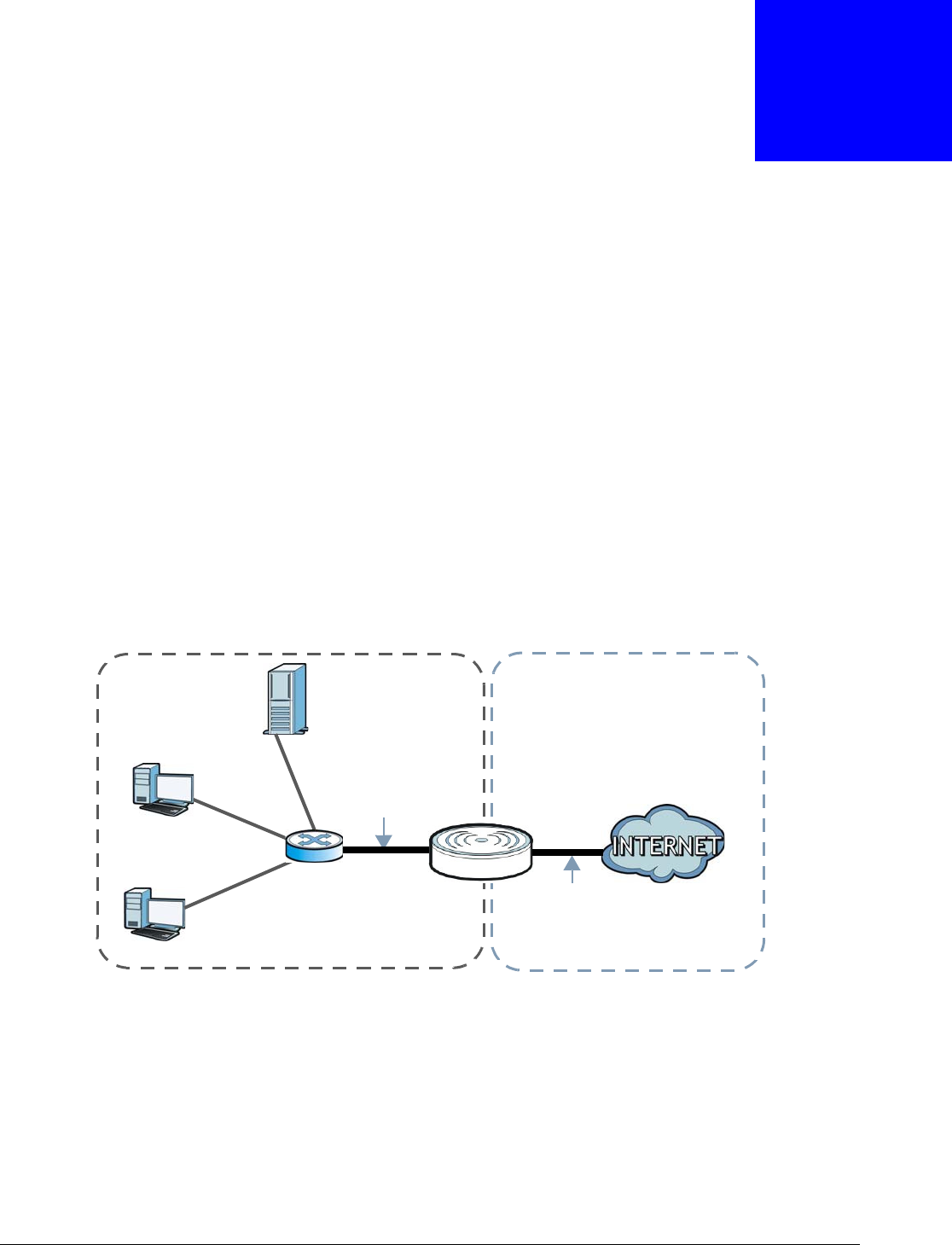
EMG3425-Q10A User’s Guide
99
CHAPTER 12
NAT
12.1 Overview
NAT (Network Address Translation - NAT, RFC 1631) is the translation of the IP address of a host in
a packet. For example, the source address of an outgoing packet, used within one network is
changed to a different IP address known within another network.
The figure below is a simple illustration of a NAT network. You want to assign ports 21-25 to one
FTP, Telnet and SMTP server (A in the example), port 80 to another (B in the example) and assign
a default server IP address of 192.168.1.35 to a third (C in the example).
You assign the LAN IP addresses to the devices (A to D) connected to your EMG3425-Q10A. The
ISP assigns the WAN IP address. The NAT network appears as a single host on the Internet. All
traffic coming from A to D going out to the Internet use the IP address of the EMG3425-Q10A,
which is 192.168.1.1.
Figure 55 NAT Example
This chapter discusses how to configure NAT on the EMG3425-Q10A.
Note: You must create a firewall rule in addition to setting up NAT, to allow traffic from
the WAN to be forwarded through the EMG3425-Q10A.
12.1.1 What You Can Do
•Use the Ge n e r a l screen to enable NAT (Section 12.2 on page 101).
A: 192.168.1.33
B: 192.168.1.34
C: 192.168.1.35
IP address
192.168.1.1
WANLAN
assigned by ISP
FTP, Telnet, SNMP
Port 80
Ports 21 to 25

Chapter 12 NAT
EMG3425-Q10A User’s Guide
100
•Use the Port Forw arding screen to set a default server and change your EMG3425-Q10A’s port
forwarding settings to forward incoming service requests to the server(s) on your local network
(Section 12.3 on page 102).
•Use the Port Trigger screen to change your EMG3425-Q10A’s trigger port settings (Section
12.5.3 on page 107).
12.1.2 What You Need To Know
The following terms and concepts may help as you read through this chapter.
Inside/Outside
This denotes where a host is located relative to the EMG3425-Q10A, for example, the computers of
your subscribers are the inside hosts, while the web servers on the Internet are the outside hosts.
Global/Local
This denotes the IP address of a host in a packet as the packet traverses a router, for example, the
local address refers to the IP address of a host when the packet is in the local network, while the
global address refers to the IP address of the host when the same packet is traveling in the WAN
side.
Note: Inside/outside refers to the location of a host, while global/local refers to the IP
address of a host used in a packet.
An inside local address (ILA) is the IP address of an inside host in a packet when the packet is still
in the local network, while an inside global address (IGA) is the IP address of the same inside host
when the packet is on the WAN side. The following table summarizes this information.
Note: NAT never changes the IP address (either local or global) of an outside host.
What NAT Does
In the simplest form, NAT changes the source IP address in a packet received from a subscriber
(the inside local address) to another (the inside global address) before forwarding the packet to the
WAN side. When the response comes back, NAT translates the destination address (the inside
global address) back to the inside local address before forwarding it to the original inside host. Note
that the IP address (either local or global) of an outside host is never changed.
The global IP addresses for the inside hosts can be either static or dynamically assigned by the ISP.
In addition, you can designate servers, for example, a web server and a telnet server, on your local
Table 38 NAT Definitions
ITEM DESCRIPTION
Inside This refers to the host on the LAN.
Outside This refers to the host on the WAN.
Local This refers to the packet address (source or destination) as the packet travels on the LAN.
Global This refers to the packet address (source or destination) as the packet travels on the WAN.
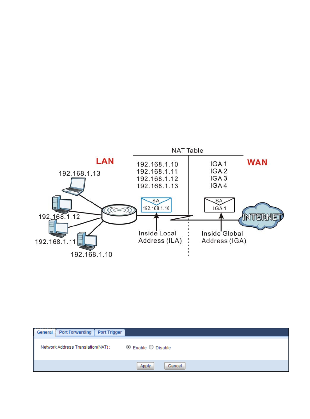
Chapter 12 NAT
EMG3425-Q10A User’s Guide
101
network and make them accessible to the outside world. If you do not define any servers, NAT
offers the additional benefit of firewall protection. With no servers defined, your EMG3425-Q10A
filters out all incoming inquiries, thus preventing intruders from probing your network. For more
information on IP address translation, refer to RFC 1631, The I P Network Address Translator ( NAT).
How NAT Works
Each packet has two addresses – a source address and a destination address. For outgoing packets,
the ILA (Inside Local Address) is the source address on the LAN, and the IGA (Inside Global
Address) is the source address on the WAN. For incoming packets, the ILA is the destination
address on the LAN, and the IGA is the destination address on the WAN. NAT maps private (local)
IP addresses to globally unique ones required for communication with hosts on other networks. It
replaces the original IP source address in each packet and then forwards it to the Internet. The
EMG3425-Q10A keeps track of the original addresses and port numbers so incoming reply packets
can have their original values restored. The following figure illustrates this.
Figure 56 How NAT Works
12.2 General
Use this screen to enable NAT and set a default server. Click Ne t w ork > N AT to open the Gener a l
screen.
Figure 57 Network > NAT > General

Chapter 12 NAT
EMG3425-Q10A User’s Guide
102
The following table describes the labels in this screen.
12.3 Port Forwarding Screen
Use this screen to forward incoming service requests to the server(s) on your local network and set
a default server. You may enter a single port number or a range of port numbers to be forwarded,
and the local IP address of the desired server. The port number identifies a service; for example,
web service is on port 80 and FTP on port 21. In some cases, such as for unknown services or
where one server can support more than one service (for example both FTP and web service), it
might be better to specify a range of port numbers.
In addition to the servers for specified services, NAT supports a default server. A service request
that does not have a server explicitly designated for it is forwarded to the default server. If the
default is not defined, the service request is simply discarded.
Note: Many residential broadband ISP accounts do not allow you to run any server
processes (such as a Web or FTP server) from your location. Your ISP may
periodically check for servers and may suspend your account if it discovers any
active services at your location. If you are unsure, refer to your ISP.
Port forwarding allows you to define the local servers to which the incoming services will be
forwarded. To change your EMG3425-Q10A’s port forwarding settings, click Net w ork > N AT >
Port Forw arding. The screen appears as shown.
Note: If you do not assign a Defa ult Serve r, the EMG3425-Q10A discards all packets
received for ports that are not specified in this screen or remote management.
Refer to Appendix C on page 231 for port numbers commonly used for particular services.
Table 39 Network > NAT > General
LABEL DESCRIPTION
Network Address
Transla tion (NAT)
Network Address Translation (NAT) allows the translation of an Internet protocol
address used within one network (for example a private IP address used in a local
network) to a different IP address known within another network (for example a public
IP address used on the Internet).
Select En able to activate NAT. Select Disable to turn it off.
Apply Click Apply to save your changes back to the EMG3425-Q10A.
Cancel Click Cancel to begin configuring this screen afresh.
Chapter 12 NAT
EMG3425-Q10A User’s Guide
103
Figure 58 Network > NAT > Port Forwarding
The following table describes the labels in this screen.
Table 40 Network > NAT > Port Forwarding
LABEL DESCRIPTION
Default Server Setup
Default Server In addition to the servers for specified services, NAT supports a default server. A default
server receives packets from ports that are not specified in the Port Forw arding
screen. You can decide whether you want to use the default server or specify a server
manually.
Select this to use the default server.
Change to Server Select this and manually enter the server’s IP address.
Service Name Select a pre-defined service from the drop-down list box. The pre-defined service port
number(s) and protocol will be displayed in the port forwarding summary table.
Otherwise, select User de fine to manually enter the port number(s) and select the IP
protocol.
Service Protocol Select the transport layer protocol supported by this virtual server. Choices are TCP,
UDP, or TCP_ UD P.
If you have chosen a pre-defined service in the Service N a m e field, the protocol will be
configured automatically.
Server IP Address Enter the inside IP address of the virtual server here and click Add to add it in the port
forwarding summary table.
#This is the number of an individual port forwarding server entry.
Status This icon is turned on when the rule is enabled.
Name This field displays a name to identify this rule.
Protocol This is the transport layer protocol used for the service.
Port This field displays the port number(s).
Server IP Address This field displays the inside IP address of the server.
Modify Click the Edit icon to open the edit screen where you can modify an existing rule.
Click the D ele t e icon to remove a rule.
Chapter 12 NAT
EMG3425-Q10A User’s Guide
104
12.3.1 Port Forwarding Edit Screen
This screen lets you edit a port forwarding rule. Click a rule’s Edit icon in the Por t For w a rding
screen to open the following screen.
Figure 59 Network > NAT > Port Forwarding Edit
The following table describes the labels in this screen.
Apply Click Apply to save your changes back to the EMG3425-Q10A.
Cancel Click Can cel to begin configuring this screen afresh.
Table 40 Network > NAT > Port Forwarding (continued)
LABEL DESCRIPTION
Table 41 Network > NAT > Port Forwarding Edit
LABEL DESCRIPTION
Port Forwarding Select Enable to turn on this rule and the requested service can be forwarded to the host
with a specified internal IP address.
Select Disable to disallow forwarding of these ports to an inside server without having to
delete the entry.
Service Name Select Use r define and type a name (of up to 31 printable characters) to identify this rule
in the first field next to Service Nam e. Otherwise, select a predefined service in the
second field next to Se r vice N a m e. The predefined service name and port number(s) will
display in the Se r vice N a m e and Port fields.
Protocol Select the transport layer protocol supported by this virtual server. Choices are TCP, UDP,
or TCP_ UD P.
If you have chosen a pre-defined service in the Se r vice Nam e field, the protocol will be
configured automatically.
Port Type a port number(s) to define the service to be forwarded to the specified server.
To specify a range of ports, enter a hyphen (-) between the first port and the last port,
such as 10-.
Server IP
Address
Type the IP address of the server on your LAN that receives packets from the port(s)
specified in the Port field.
Back Click Ba ck to return to the previous screen.
Apply Click Apply to save your changes back to the EMG3425-Q10A.
Cancel Click Cancel to begin configuring this screen afresh.
Chapter 12 NAT
EMG3425-Q10A User’s Guide
105
12.4 Port Trigger Screen
To change your EMG3425-Q10A’s trigger port settings, click N et w ork > N AT > Por t Trigger. The
screen appears as shown.
Note: Only one LAN computer can use a trigger port (range) at a time.
Figure 60 Network > NAT > Port Trigger
The following table describes the labels in this screen.
Table 42 Network > NAT > Port Trigger
LABEL DESCRIPTION
#This is the rule index number (read-only).
Name Type a unique name (up to 15 characters) for identification purposes. All characters are
permitted - including spaces.
Incoming Incoming is a port (or a range of ports) that a server on the WAN uses when it sends out
a particular service. The EMG3425-Q10A forwards the traffic with this port (or range of
ports) to the client computer on the LAN that requested the service.
Port Type a port number or the starting port number in a range of port numbers.
End Port Type a port number or the ending port number in a range of port numbers.
Trigger The trigger port is a port (or a range of ports) that causes (or triggers) the EMG3425-
Q10A to record the IP address of the LAN computer that sent the traffic to a server on the
WAN.
Port Type a port number or the starting port number in a range of port numbers.
End Port Type a port number or the ending port number in a range of port numbers.
Apply Click Apply to save your changes back to the EMG3425-Q10A.
Cancel Click Can cel to begin configuring this screen afresh.
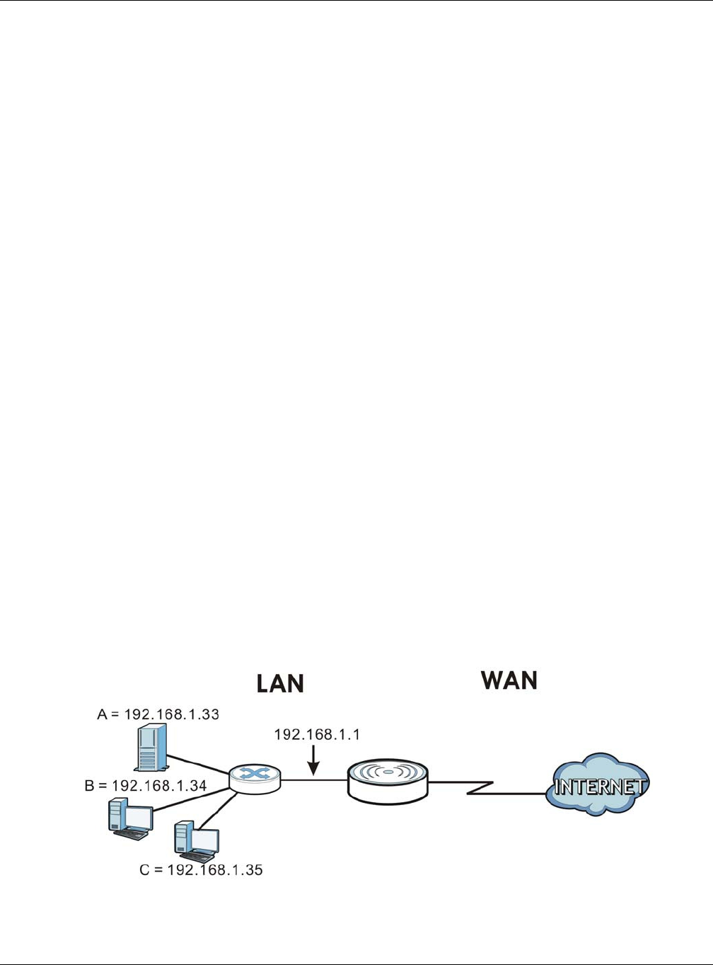
Chapter 12 NAT
EMG3425-Q10A User’s Guide
106
12.5 Technical Reference
The following section contains additional technical information about the EMG3425-Q10A features
described in this chapter.
12.5.1 NATPort Forwarding: Services and Port Numbers
A port forwarding set is a list of inside (behind NAT on the LAN) servers, for example, web or FTP,
that you can make accessible to the outside world even though NAT makes your whole inside
network appear as a single machine to the outside world.
Use the Port Forw a rding screen to forward incoming service requests to the server(s) on your
local network. You may enter a single port number or a range of port numbers to be forwarded, and
the local IP address of the desired server. The port number identifies a service; for example, web
service is on port 80 and FTP on port 21. In some cases, such as for unknown services or where one
server can support more than one service (for example both FTP and web service), it might be
better to specify a range of port numbers.
In addition to the servers for specified services, NAT supports a default server. A service request
that does not have a server explicitly designated for it is forwarded to the default server. If the
default is not defined, the service request is simply discarded.
Note: Many residential broadband ISP accounts do not allow you to run any server
processes (such as a Web or FTP server) from your location. Your ISP may
periodically check for servers and may suspend your account if it discovers any
active services at your location. If you are unsure, refer to your ISP.
12.5.2 NAT Port Forwarding Example
Let's say you want to assign ports 21-25 to one FTP, Telnet and SMTP server (A in the example),
port 80 to another (B in the example) and assign a default server IP address of 192.168.1.35 to a
third (C in the example). You assign the LAN IP addresses and the ISP assigns the WAN IP address.
The NAT network appears as a single host on the Internet.
Figure 61 Multiple Servers Behind NAT Example
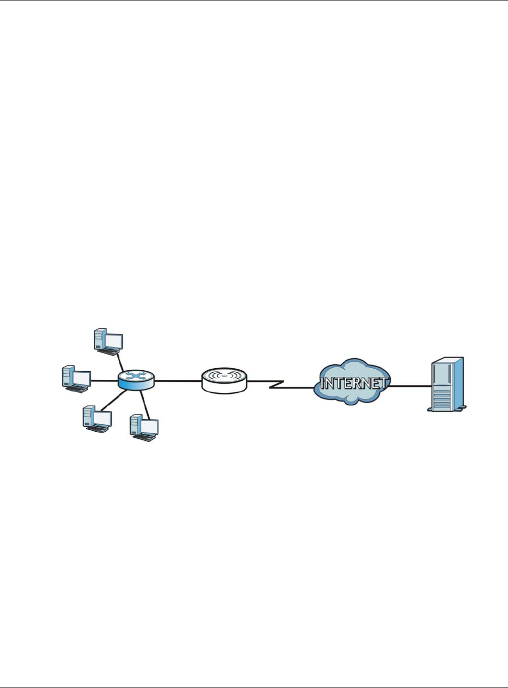
Chapter 12 NAT
EMG3425-Q10A User’s Guide
107
12.5.3 Trigger Port Forwarding
Some services use a dedicated range of ports on the client side and a dedicated range of ports on
the server side. With regular port forwarding you set a forwarding port in NAT to forward a service
(coming in from the server on the WAN) to the IP address of a computer on the client side (LAN).
The problem is that port forwarding only forwards a service to a single LAN IP address. In order to
use the same service on a different LAN computer, you have to manually replace the LAN
computer's IP address in the forwarding port with another LAN computer's IP address.
Trigger port forwarding solves this problem by allowing computers on the LAN to dynamically take
turns using the service. The EMG3425-Q10A records the IP address of a LAN computer that sends
traffic to the WAN to request a service with a specific port number and protocol (a "trigger" port).
When the EMG3425-Q10A's WAN port receives a response with a specific port number and protocol
("incoming" port), the EMG3425-Q10A forwards the traffic to the LAN IP address of the computer
that sent the request. After that computer’s connection for that service closes, another computer on
the LAN can use the service in the same manner. This way you do not need to configure a new IP
address each time you want a different LAN computer to use the application.
12.5.4 Trigger Port Forwarding Example
The following is an example of trigger port forwarding.
Figure 62 Trigger Port Forwarding Process: Example
1Jane requests a file from the Real Audio server (port 7070).
2Port 7070 is a “trigger” port and causes the EMG3425-Q10A to record Jane’s computer IP address.
The EMG3425-Q10A associates Jane's computer IP address with the "incoming" port range of 6970-
7170.
3The Real Audio server responds using a port number ranging between 6970-7170.
4The EMG3425-Q10A forwards the traffic to Jane’s computer IP address.
5Only Jane can connect to the Real Audio server until the connection is closed or times out. The
EMG3425-Q10A times out in three minutes with UDP (User Datagram Protocol), or two hours with
TCP/IP (Transfer Control Protocol/Internet Protocol).
Jane’s com puter
Rea l Audio Server
Port 7 0 7 0

Chapter 12 NAT
EMG3425-Q10A User’s Guide
108
12.5.5 Two Points To Remember About Trigger Ports
1Trigger events only happen on data that is coming from inside the EMG3425-Q10A and going to the
outside.
2If an application needs a continuous data stream, that port (range) will be tied up so that another
computer on the LAN can’t trigger it.
EMG3425-Q10A User’s Guide
109
CHAPTER 13
DDNS
13.1 Overview
DDNS services let you use a domain name with a dynamic IP address.
13.1.1 What You Need To Know
The following terms and concepts may help as you read through this chapter.
What is DDNS?
Dynamic Domain Name Service (DDNS) services let you use a fixed domain name with a dynamic
IP address. Users can always use the same domain name instead of a different dynamic IP address
that changes each time to connect to the EMG3425-Q10A or a server in your network.
Note: The EMG3425-Q10A must have a public global IP address and you should have
your registered DDNS account information on hand.
13.2 General
To change your EMG3425-Q10A’s DDNS, click Ne t w ork > DDNS. The screen appears as shown.
Figure 63 Dynamic DNS

Chapter 13 DDNS
EMG3425-Q10A User’s Guide
110
The following table describes the labels in this screen.
Table 43 Dynamic DNS
LABEL DESCRIPTION
Dynamic DNS Select Enable to use dynamic DNS. Select Disa ble to turn this feature off.
Service Provider Select the name of your Dynamic DNS service provider.
Host Name Enter a host names in the field provided. You can specify up to two host names in the
field separated by a comma (",").
Username Enter your user name.
Password Enter the password assigned to you.
Apply Click Apply to save your changes back to the EMG3425-Q10A.
Cancel Click Cancel to begin configuring this screen afresh.
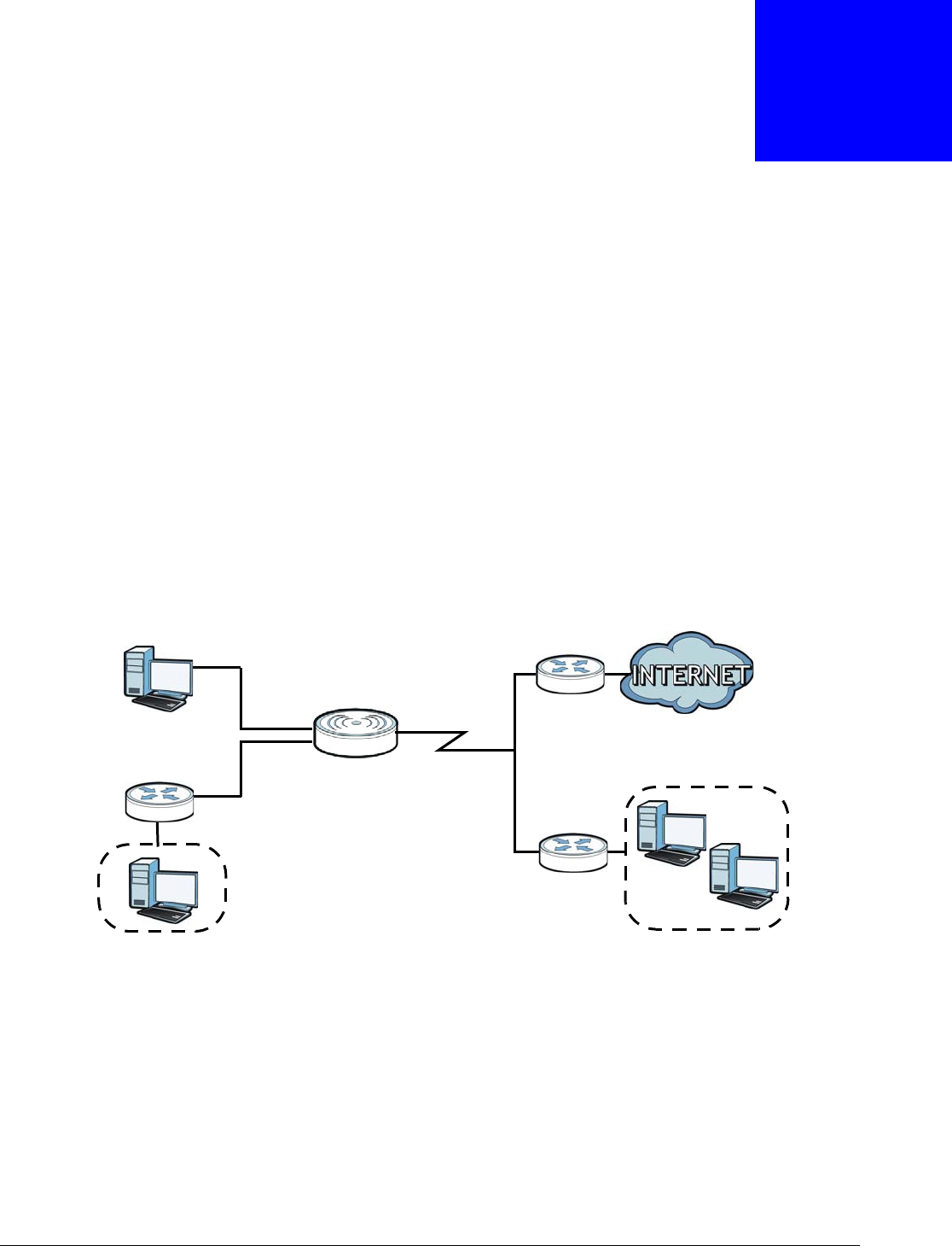
EMG3425-Q10A User’s Guide
111
CHAPTER 14
Static Route
14.1 Overview
This chapter shows you how to configure static routes for your EMG3425-Q10A.
The EMG3425-Q10A usually uses the default gateway to route outbound traffic from computers on
the LAN to the Internet. To have the EMG3425-Q10A send data to devices not reachable through
the default gateway, use static routes.
For example, the next figure shows a computer (A) connected to the EMG3425-Q10A’s LAN
interface. The EMG3425-Q10A routes most traffic from A to the Internet through the EMG3425-
Q10A’s default gateway (R1 ). You create one static route to connect to services offered by your ISP
behind router R2 . You create another static route to communicate with a separate network behind
a router R3 connected to the LAN.
Figure 64 Example of Static Routing Topology
14.2 IP Static Route Screen
Click N et w ork > Sta t ic Rout e to open the St at ic Route screen.
WAN
R1
R2
A
R3
LAN
Chapter 14 Static Route
EMG3425-Q10A User’s Guide
112
Figure 65 Network > Static Route
The following table describes the labels in this screen.
14.2.1 Add/Edit Static Route
Click the Add Sta tic Rout e button or a rule’s Ed it icon in the Sta t ic Rout e screen. Use this screen
to configure the required information for a static route.
Figure 66 Network > Static Route: Add/Edit
Table 44 Network > Static Route
LABEL DESCRIPTION
Add Static Route Click this to create a new rule.
#This is the number of an individual static route.
Status This field indicates whether the rule is active (yellow bulb) or not (gray bulb).
Name This field displays a name to identify this rule.
Destination This parameter specifies the IP network address of the final destination. Routing is always
based on network number.
Gateway This is the IP address of the gateway. The gateway is a router or switch on the same
network segment as the device's LAN or WAN port. The gateway helps forward packets to
their destinations.
Subnet Mask This parameter specifies the IP network subnet mask of the final destination.
Interface This is the WAN interface through which the traffic is routed.
Modify Click the Ed it icon to open a screen where you can modify an existing rule.
Click the Delete icon to remove a rule from the EMG3425-Q10A.
Apply Click Apply to save your changes back to the EMG3425-Q10A.
Cancel Click Cancel to begin configuring this screen afresh.

Chapter 14 Static Route
EMG3425-Q10A User’s Guide
113
The following table describes the labels in this screen.
Table 45 Network > Static Route: Add/Edit
LABEL DESCRIPTION
Static Route Select to enable or disable this rule.
Route Name Type a name to identify this rule. You can use up to 31 printable English keyboard
characters, including spaces.
Destination IP
Address
This parameter specifies the IP network address of the final destination. Routing is always
based on network number. If you need to specify a route to a single host, use a subnet
mask of 255.255.255.255 in the subnet mask field to force the network number to be
identical to the host ID.
IP Subnet Mask Enter the IP subnet mask here.
Use Gateway IP
Address
Select to enable or disable this rule.
Gateway IP
Address
Enter the IP address of the next-hop gateway. The gateway is a router or switch on the
same segment as your EMG3425-Q10A's interface(s). The gateway helps forward packets
to their destinations.
Use Interface Select a WAN interface through which the traffic is sent. You must have the WAN
interface(s) already configured in the W AN screens.
Back Click Ba ck to return to the previous screen without saving.
Apply Click Apply to save your changes back to the EMG3425-Q10A.
Cancel Click Cancel to set every field in this screen to its last-saved value.
EMG3425-Q10A User’s Guide
114
CHAPTER 15
Interface Group
15.1 Overview
By default, all LAN and WAN interfaces on the EMG3425-Q10A are in the same group and can
communicate with each other. Each group acts as an independent network on the EMG3425-Q10A.
15.2 The Interface Group Screen
You can manually add a LAN and/or WLAN interface to a new group. Click Ne t w or k > I nterface
Grou p to open the following screen.
Figure 67 Network > Interface Group
The following table describes the fields in this screen.
Table 46 Network > Interface Group
LABEL DESCRIPTION
Add Click this to add a new interface grouping rule.
You must configure a WAN connection before you can add a new interface
grouping rule. See Chapter 8 on page 57 for more information.
Interface Grouping Rules
Name This shows the descriptive name of the group.
WAN Interface This shows the WAN interfaces in the group.
LAN Interfaces This shows the LAN and/or WLAN interfaces in the group.
Criteria This shows the filtering criteria for the goup.
Delete Click the De le t e icon to remove the group.
Chapter 15 Interface Group
EMG3425-Q10A User’s Guide
115
15.2.1 Add Interface Group
Click the Add button in the I nterface Grou p screen to open the following screen. Use this screen
to create a new interface group.
Note: An interface can belong to a group only.
Figure 68 Interface Group > Add New Group
The following table describes the fields in this screen.
Table 47 Interface Group > Add New Group
LABEL DESCRIPTION
Group Name Enter a name to identify this group.
WAN Interfaces
used in the group
Select a WAN interface to be used in this group.
Select N on e to not add a WAN interface to this group.
Grouped LAN
Interfaces
Available LAN
Interfaces
Select a LAN or wireless LAN interface in the Ava ila ble LAN I nterfa ces and
use the left-facing arrow to move it to the Gr ouped LAN I nterfa ces to add
the interface to this group.
To remove a LAN or wireless LAN interface from the Groupe d LAN I n t e rfaces,
use the righ-facing arrow.
Add Click this button to create a new rule.
Delete Click the De le t e icon to remove this rule from the EMG3425-Q10A.
DHCP Option Rules
Chapter 15 Interface Group
EMG3425-Q10A User’s Guide
116
15.2.2 Add Interface Group Criteria
Click the Add button in the I nterface Grou p screen to open the following screen.
Figure 69 Interface Group > Add New Group > Add Interface Group Criteria
The following table describes the fields in this screen.
#This shows the index number of the rule.
Filter Criteria This shows the filtering criteria. The LAN interface on which the matched traffic
is received will belong to this group automatically.
Back Click this button to return to the previous screen without saving any changes.
Apply Click this button to save your settings back to the EMG3425-Q10A.
Cancel Click Can cel to begin configuring this screen afresh.
Table 47 Interface Group > Add New Group
LABEL DESCRIPTION
Table 48 Interface Group > Add New Group > Add Interface Group Criteria
LABEL DESCRIPTION
DHCP Option 60 Select this option and enter the Vendor Class Identifier (Option 60) of the
matched traffic, such as the type of the hardware or firmware.
Vendor ID Enter the identification number assigned to the company by the IANA (Internet
Assigned Numbers Authority).
Apply Click this button to save your settings back to the EMG3425-Q10A.
Cancel Click Can cel to begin configuring this screen afresh.
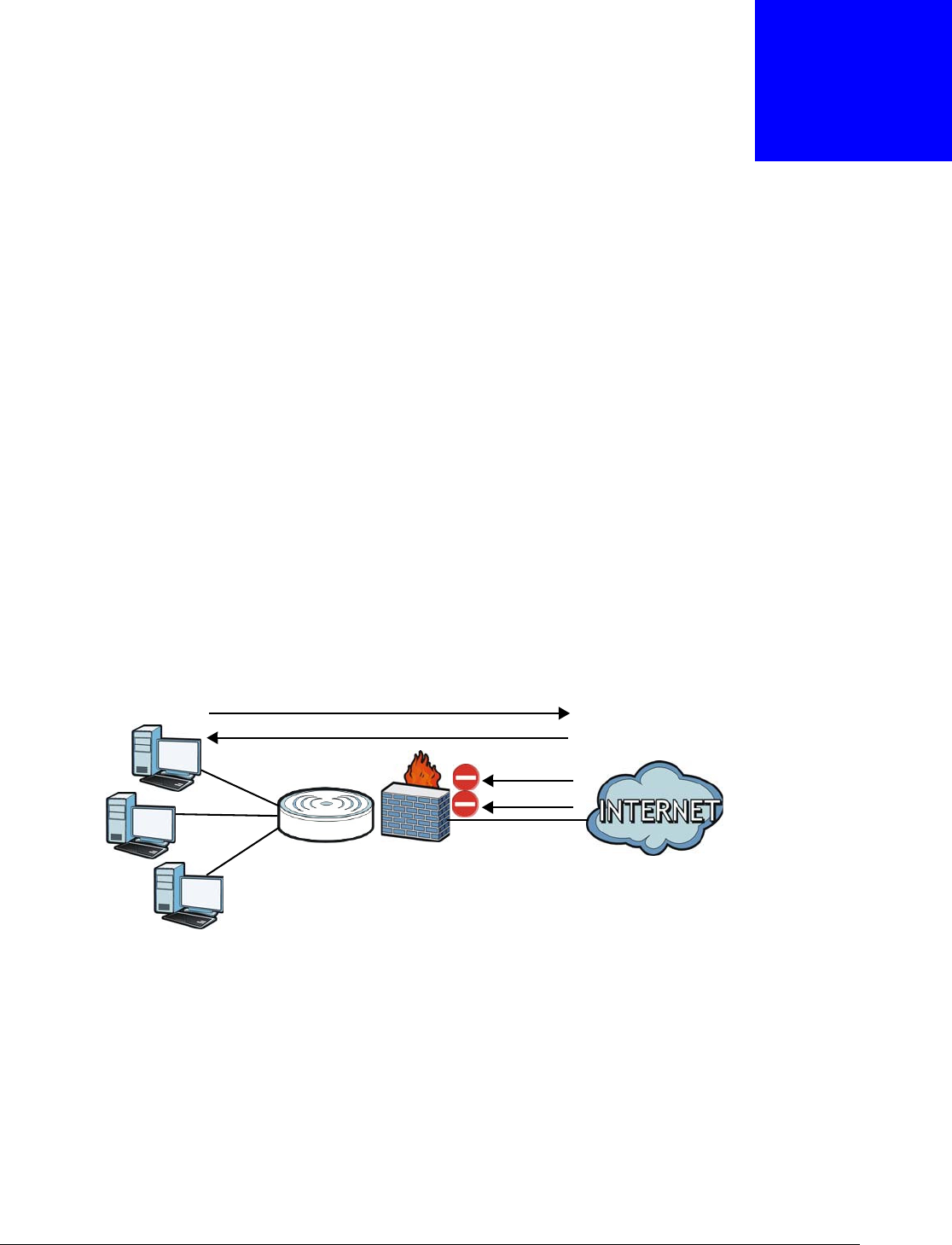
EMG3425-Q10A User’s Guide
117
CHAPTER 16
Firewall
16.1 Overview
Use these screens to enable and configure the firewall that protects your EMG3425-Q10A and your
LAN from unwanted or malicious traffic.
Enable the firewall to protect your LAN computers from attacks by hackers on the Internet and
control access between the LAN and WAN. By default the firewall:
• allows traffic that originates from your LAN computers to go to all of the networks.
• blocks traffic that originates on the other networks from going to the LAN.
The following figure illustrates the default firewall action. User A can initiate an IM (Instant
Messaging) session from the LAN to the WAN (1). Return traffic for this session is also allowed (2).
However other traffic initiated from the WAN is blocked (3 and 4).
Figure 70 Default Firewall Action
16.1.1 What You Can Do
•Use the Ge n e r a l screen to enable or disable the EMG3425-Q10A’s firewall (Section 16.2 on page
119).
•Use the Service s screen enable service blocking, enter/delete/modify the services you want to
block and the date/time you want to block them (Section 16.3 on page 119).
16.1.2 What You Need To Know
The following terms and concepts may help as you read through this chapter.
WAN
LAN
3
4
1
2
A

Chapter 16 Firewall
EMG3425-Q10A User’s Guide
118
What is a Firewall?
Originally, the term “firewall” referred to a construction technique designed to prevent the spread of
fire from one room to another. The networking term "firewall" is a system or group of systems that
enforces an access-control policy between two networks. It may also be defined as a mechanism
used to protect a trusted network from a network that is not trusted. Of course, firewalls cannot
solve every security problem. A firewall is one of the mechanisms used to establish a network
security perimeter in support of a network security policy. It should never be the only mechanism or
method employed. For a firewall to guard effectively, you must design and deploy it appropriately.
This requires integrating the firewall into a broad information-security policy. In addition, specific
policies must be implemented within the firewall itself.
Stateful Inspection Firewall
Stateful inspection firewalls restrict access by screening data packets against defined access rules.
They make access control decisions based on IP address and protocol. They also "inspect" the
session data to assure the integrity of the connection and to adapt to dynamic protocols. These
firewalls generally provide the best speed and transparency; however, they may lack the granular
application level access control or caching that some proxies support. Firewalls, of one type or
another, have become an integral part of standard security solutions for enterprises.
About the EMG3425-Q10A Firewall
The EMG3425-Q10A’s firewall feature physically separates the LAN and the WAN and acts as a
secure gateway for all data passing between the networks.
It is a stateful inspection firewall and is designed to protect against Denial of Service attacks when
activated (click the General tab under Fir e w all and then click the Enable Fir e w a ll check box).
The EMG3425-Q10A's purpose is to allow a private Local Area Network (LAN) to be securely
connected to the Internet. The EMG3425-Q10A can be used to prevent theft, destruction and
modification of data, as well as log events, which may be important to the security of your network.
The EMG3425-Q10A is installed between the LAN and a broadband modem connecting to the
Internet. This allows it to act as a secure gateway for all data passing between the Internet and the
LAN.
The EMG3425-Q10A has one Ethernet WAN port and four Ethernet LAN ports, which are used to
physically separate the network into two areas.The WAN (Wide Area Network) port attaches to the
broadband (cable or DSL) modem to the Internet.
The LAN (Local Area Network) port attaches to a network of computers, which needs security from
the outside world. These computers will have access to Internet services such as e-mail, FTP and
the World Wide Web. However, "inbound access" is not allowed (by default) unless the remote host
is authorized to use a specific service.
Guidelines For Enhancing Security With Your Firewall
1Change the default password via Web Configurator.
2Think about access control before you connect to the network in any way, including attaching a
modem to the port.
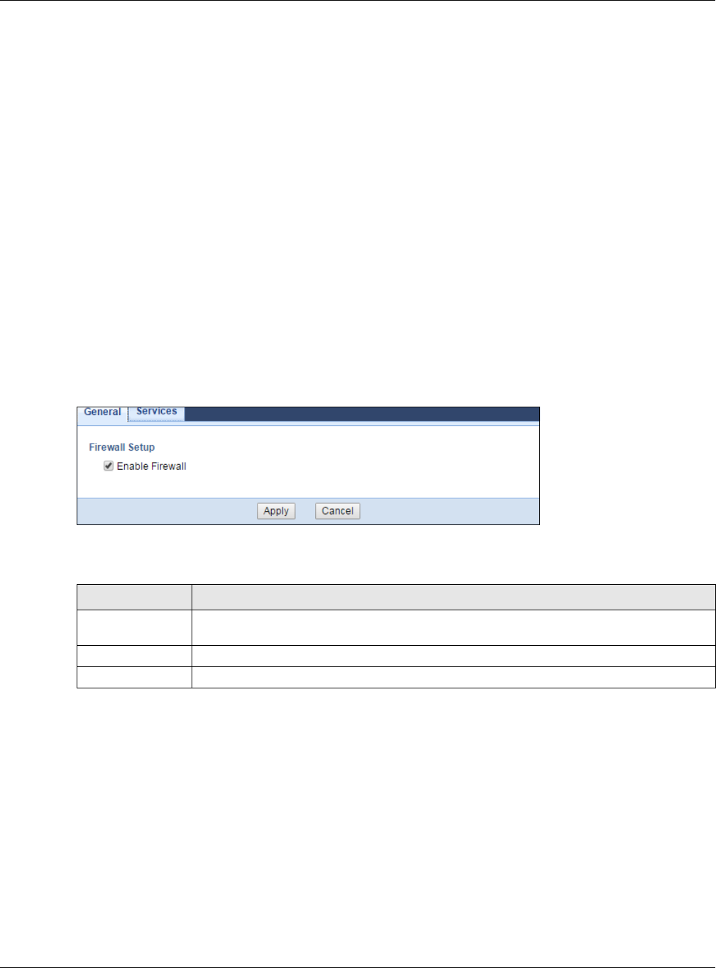
Chapter 16 Firewall
EMG3425-Q10A User’s Guide
119
3Limit who can access your router.
4Don't enable any local service (such as NTP) that you don't use. Any enabled service could present
a potential security risk. A determined hacker might be able to find creative ways to misuse the
enabled services to access the firewall or the network.
5For local services that are enabled, protect against misuse. Protect by configuring the services to
communicate only with specific peers, and protect by configuring rules to block packets for the
services at specific interfaces.
6Protect against IP spoofing by making sure the firewall is active.
7Keep the firewall in a secured (locked) room.
16.2 General Screen
Use this screen to enable or disable the EMG3425-Q10A’s firewall, and set up firewall logs. Click
Se cu r it y > Firew all to open the Ge n e ral screen.
Figure 71 Security > Firewall > General l
The following table describes the labels in this screen.
16.3 Services Screen
If an outside user attempts to probe an unsupported port on your EMG3425-Q10A, an ICMP
response packet is automatically returned. This allows the outside user to know the EMG3425-Q10A
exists. Use this screen to prevent the ICMP response packet from being sent. This keeps outsiders
from discovering your EMG3425-Q10A when unsupported ports are probed.
You can also use this screen to enable service blocking, enter/delete/modify the services you want
to block and the date/time you want to block them.
Click Se curit y > Firew all > Services. The screen appears as shown next.
Table 49 Security > Firewall > General
LABEL DESCRIPTION
Enable Firewall Select this check box to activate the firewall. The EMG3425-Q10A performs access control
and protects against Denial of Service (DoS) attacks when the firewall is activated.
Apply Click Apply to save the settings.
Cancel Click Can cel to start configuring this screen again.
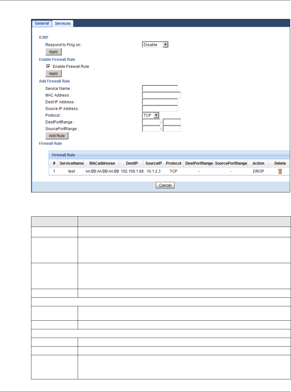
Chapter 16 Firewall
EMG3425-Q10A User’s Guide
120
Figure 72 Security > Firewall > Services l
The following table describes the labels in this screen.
Table 50 Security > Firewall > Services
LABEL DESCRIPTION
LABEL DESCRIPTION
ICMP Internet Control Message Protocol is a message control and error-reporting protocol
between a host server and a gateway to the Internet. ICMP uses Internet Protocol (IP)
datagrams, but the messages are processed by the TCP/IP software and directly apparent
to the application user.
Respond to Ping
on
The EMG3425-Q10A will not respond to any incoming Ping requests when Disa ble is
selected. Select LAN to reply to incoming LAN Ping requests. Select W AN to reply to
incoming WAN Ping requests. Otherwise select LAN & W AN to reply to all incoming LAN
and WAN Ping requests.
Apply Click Apply to save the settings.
Enable Firewall Rule
Enable Firewall
Rule
Select this check box to activate the firewall rules that you define (see Add Fir ew all Rule
below).
Apply Click Apply to save the settings.
Add Firewall Rule
Service Name Enter a name that identifies or describes the firewall rule.
MAC Address Enter the MAC address of the computer for which the firewall rule applies.
Dest IP Address Enter the IP address of the computer to which traffic for the application or service is
entering.
The EMG3425-Q10A applies the firewall rule to traffic initiating from this computer.

Chapter 16 Firewall
EMG3425-Q10A User’s Guide
121
See Appendix C on page 231 for commonly used services and port numbers.
Source IP Address Enter the IP address of the computer that initializes traffic for the application or service.
The EMG3425-Q10A applies the firewall rule to traffic initiating from this computer.
Protocol Select the protocol (TCP, UDP or I CM P) used to transport the packets for which you want
to apply the firewall rule.
Dest Port Range Enter the port number/range of the destination that define the traffic type, for example
TCP port 80 defines web traffic.
Source Port
Range
Enter the port number/range of the source that define the traffic type, for example TCP
port 80 defines web traffic.
Add Rule Click Add to save the firewall rule.
Firewall Rule
#This is your firewall rule number. The ordering of your rules is important as rules are
applied in turn.
Service Name This is a name that identifies or describes the firewall rule.
MAC address This is the MAC address of the computer for which the firewall rule applies.
Dest IP This is the IP address of the computer to which traffic for the application or service is
entering.
Source IP This is the IP address of the computer from which traffic for the application or service is
initialized.
Protocol This is the protocol (TCP, UDP or I CM P) used to transport the packets for which you want
to apply the firewall rule.
Dest Port Range This is the port number/range of the destination that define the traffic type, for example
TCP port 80 defines web traffic.
Source Port
Range
This is the port number/range of the source that define the traffic type, for example TCP
port 80 defines web traffic.
Action DROP - Traffic matching the conditions of the firewall rule are stopped.
Delete Click De le t e to remove the firewall rule.
Cancel Click Can cel to start configuring this screen again.
Table 50 Security > Firewall > Services (continued)
LABEL DESCRIPTION
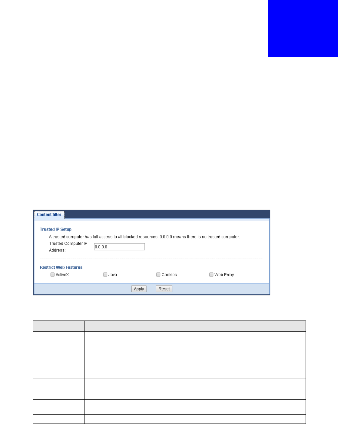
EMG3425-Q10A User’s Guide
122
CHAPTER 17
Content Filtering
17.1 Overview
This chapter shows you how to configure content filtering. Content filtering is the ability to block
certain web features.
17.2 Content Filter
Use this screen to restrict web features, and designate a trusted computer. Click Se curit y >
Cont e nt Filte r to open the Conte n t Filter screen.
Figure 73 Security > Content Filter
The following table describes the labels in this screen.
Table 51 Security > Content Filter
LABEL DESCRIPTION
Trusted IP Setup To enable this feature, type an IP address of any one of the computers in your network
that you want to have as a trusted computer. This allows the trusted computer to have
full access to all features that are configured to be blocked by content filtering.
Leave this field blank to have no trusted computers.
Restrict Web
Features
Select the box(es) to restrict a feature. When you download a page containing a
restricted feature, that part of the web page will appear blank or grayed out.
ActiveX A tool for building dynamic and active Web pages and distributed object applications.
When you visit an ActiveX Web site, ActiveX controls are downloaded to your browser,
where they remain in case you visit the site again.
Java A programming language and development environment for building downloadable Web
components or Internet and intranet business applications of all kinds.
Cookies Used by Web servers to track usage and provide service based on ID.

Chapter 17 Content Filtering
EMG3425-Q10A User’s Guide
123
Web Proxy A server that acts as an intermediary between a user and the Internet to provide
security, administrative control, and caching service. When a proxy server is located on
the WAN it is possible for LAN users to circumvent content filtering by pointing to this
proxy server.
Apply Click Apply to save your changes.
Cancel Click Cancel to begin configuring this screen afresh
Table 51 Security > Content Filter (continued)
LABEL DESCRIPTION
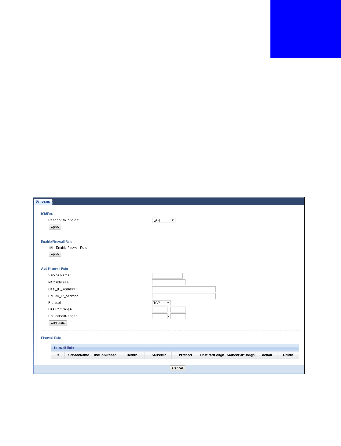
EMG3425-Q10A User’s Guide
124
CHAPTER 18
IPv6 Firewall
18.1 Overview
This chapter shows you how to enable and create IPv6 firewall rules to block unwanted IPv6 traffic.
18.2 IPv6 Firewall Screen
Click Configu r a t ion > Securit y > I Pv6 Firew all. The Service screen appears as shown.
Figure 74 Configuration > Security > IPv6 Firewall

Chapter 18 IPv6 Firewall
EMG3425-Q10A User’s Guide
125
The following table describes the labels in this screen.
Table 52 Configuration > Security > IPv6 Firewall
LABEL DESCRIPTION
ICMPv6 Internet Control Message Protocol for IPv6 (ICMPv6 or ICMP for IPv6) is defined in RFC
4443. ICMPv6 has a preceding Next Header value of 58, which is different from the
value used to identify ICMP for IPv4. ICMPv6 is an integral part of IPv6. IPv6 nodes use
ICMPv6 to report errors encountered in packet processing and perform other diagnostic
functions, such as "ping".
Respond to Ping on The EMG3425-Q10A will not respond to any incoming Ping requests when Disa ble is
selected. Select LAN to reply to incoming LAN Ping requests. Select W AN to reply to
incoming WAN Ping requests. Otherwise select LAN & W AN to reply to all incoming LAN
and WAN Ping requests.
Apply Click Apply to save the settings.
Enable Firewall Rule
Enable Firewall Rule Select this check box to activate the firewall rules that you define (see Add Firew a ll
Rule below).
Apply Click Apply to save the settings.
Add Firewall Rule
Service Name Enter a name that identifies or describes the firewall rule.
MAC Address Enter the MAC address of the computer for which the firewall rule applies.
Dest_IP_Address Enter the IPv6 address of the computer to which traffic for the application or service is
entering.
The EMG3425-Q10A applies the firewall rule to traffic destined for this computer.
Source_IP_Address Enter the IPv6 address of the computer that initializes traffic for the application or
service.
The EMG3425-Q10A applies the firewall rule to traffic initiating from this computer.
Protocol Select the protocol (TCP, UDP or I CMP) used to transport the packets for which you
want to apply the firewall rule.
Dest Port Range Enter the port number/range of the destination that defines the traffic type, for
example TCP port 80 defines web traffic.
Source Port Range Enter the port number/range of the source that defines the traffic type, for example
TCP port 80 defines web traffic.
Add Rule Click Add Rule to save the firewall rule.
Firewall Rule
#This is your firewall rule number. The ordering of your rules is important as rules are
applied in turn.
ServiceName This is a name that identifies or describes the firewall rule.
MACaddress This is the MAC address of the computer for which the firewall rule applies.
DestIP This is the IP address of the computer to which traffic for the application or service is
entering.
SourceIP This is the IP address of the computer to which traffic for the application or service is
initialized.
Protocol This is the protocol (TCP, UDP or I CMP) used to transport the packets for which you
want to apply the firewall rule.
DestPortRange This is the port number/range of the destination that defines the traffic type, for
example TCP port 80 defines web traffic.
SourcePortRange This is the port number/range of the source that defines the traffic type, for example
TCP port 80 defines web traffic.
Action DROP - Traffic matching the conditions of the firewall rule is stopped.

Chapter 18 IPv6 Firewall
EMG3425-Q10A User’s Guide
126
Delete Click D el et e to remove the firewall rule.
Cancel Click Ca nce l to restore your previously saved settings.
Table 52 Configuration > Security > IPv6 Firewall (continued)
LABEL DESCRIPTION

EMG3425-Q10A User’s Guide
127
CHAPTER 19
Parental Control
19.1 Overview
Parental controls allow you to block specific URLs. You can also define time periods and days during
which the EMG3425-Q10A performs parental control on a specific user.
19.1.1 What You Need To Know
The following terms and concepts may help as you read through this chapter.
Keyword Blocking URL Checking
The EMG3425-Q10A checks the URL’s domain name (or IP address) and file path separately when
performing keyword blocking.
The URL’s domain name or IP address is the characters that come before the first slash in the URL.
For example, with the URL www.zyxel.com.tw/news/pressroom.php, the domain name is
www.zyxel.com.tw.
The file path is the characters that come after the first slash in the URL. For example, with the URL
www.zyxel.com.tw/news/pressroom.php, the file path is news/pressroom.php.
Since the EMG3425-Q10A checks the URL’s domain name (or IP address) and file path separately, it
will not find items that go across the two. For example, with the URL www.zyxel.com.tw/news/
pressroom.php, the EMG3425-Q10A would find “tw” in the domain name (www.zyxel.com.tw). It
would also find “news” in the file path (news/pressroom.php) but it would not find “tw/news”.
19.2 Parental Control Screen
Use this screen to enable parental control, view the parental control rules and schedules.
Click Configu r at ion > Se curit y > Pa rent a l Cont r ol to open the following screen.
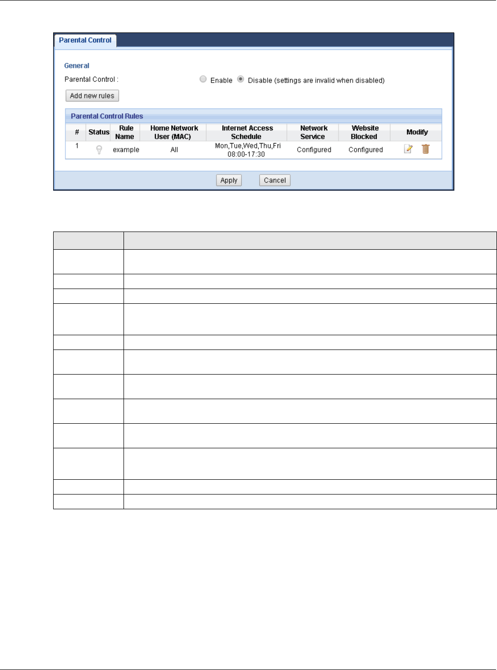
Chapter 19 Parental Control
EMG3425-Q10A User’s Guide
128
Figure 75 Security > Parental Control
The following table describes the fields in this screen.
19.2.1 Add/Edit a Parental Control Rule
Click Add new rules in the Par e n t al Cont rol screen to add a new rule or click the Edit icon next
to an existing rule to edit it. Use this screen to configure a restricted access schedule and/or URL
filtering settings to block the users on your network from accessing certain web sites.
Table 53 Security > Parental Control
LABEL DESCRIPTION
Parental
Control
Select Ena ble to activate parental control.
Add new rules Click this if you want to configure a new parental control rule.
#This shows the index number of the rule.
Status This indicates whether the rule is active or not.
A yellow bulb signifies that this rule is active. A gray bulb signifies that this rule is not active.
Rule Name This shows the name of the rule.
Home Network
User (MAC)
This shows the MAC address of the LAN user’s computer to which this rule applies.
Internet Access
Schedule
This shows the day(s) and time on which parental control is enabled.
Network
Service
This shows whether the network service is configured. If not, N one will be shown.
Website
Blocked
This shows whether the website block is configured. If not, N on e will be shown.
Modify Click the Edit icon to go to the screen where you can edit the rule.
Click the D ele t e icon to delete an existing rule.
Apply Click Apply to save your changes.
Cancel Click Cancel to restore your previously saved settings.
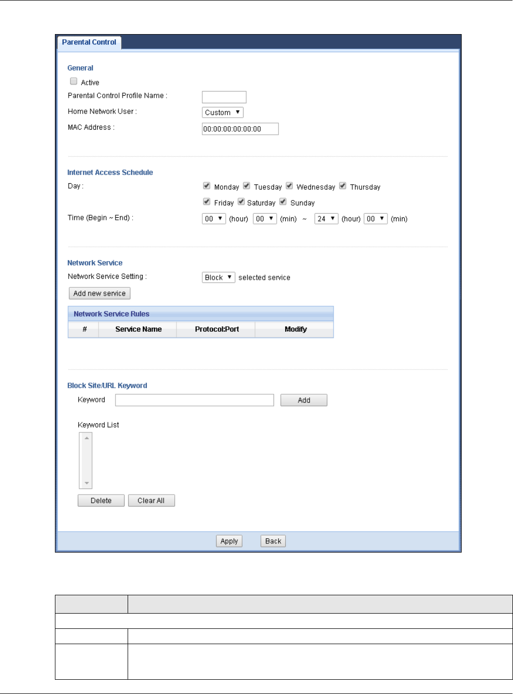
Chapter 19 Parental Control
EMG3425-Q10A User’s Guide
129
Figure 76 Security > Parental Control: Add/Edit new rules
The following table describes the fields in this screen.
Table 54 Security > Parental Control: Add/Edit new rules
LABEL DESCRIPTION
General
Active Select the checkbox to activate this parental control rule.
Parental
Control Profile
Name
Enter a descriptive name for the rule.
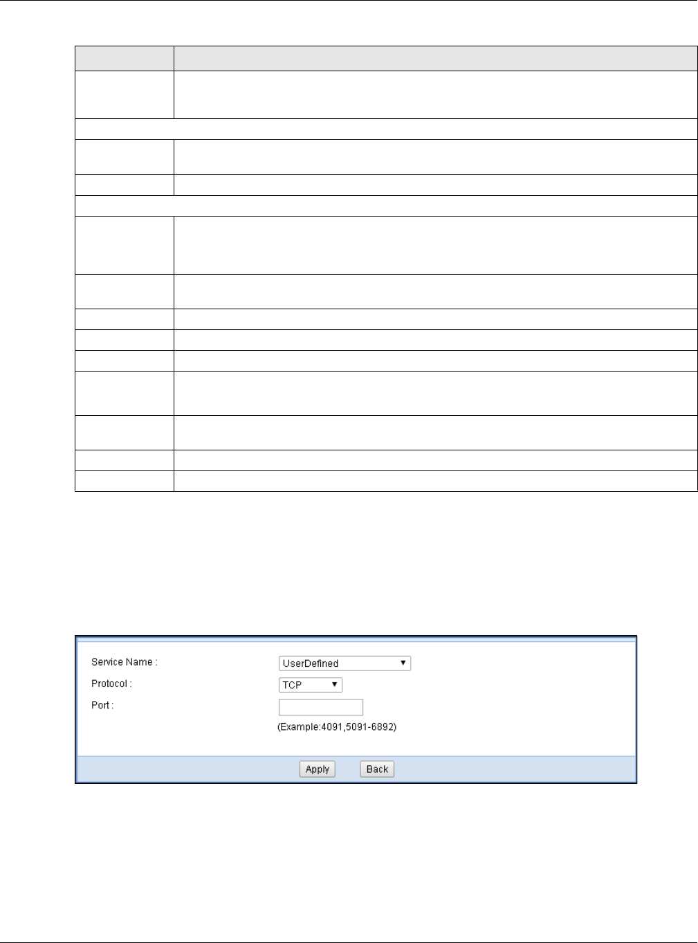
Chapter 19 Parental Control
EMG3425-Q10A User’s Guide
130
19.2.2 Add/Edit a Service
Click Add new se rvice in the Pa r ent a l Cont r ol > Add/ Edit n e w rule s screen to add a new
entry or click the Edit icon next to an existing entry to edit it. Use this screen to configure a service
rule.
Figure 77 Security > Parental Control > Add/Edit new rules > Add/Edit new service
Home Network
User
Select the LAN user that you want to apply this rule to from the drop-down list box. If you
select Cu st om , enter the LAN user’s MAC address. If you select All, the rule applies to all
LAN users.
Internet Access Schedule
Day Select check boxes for the days that you want the EMG3425-Q10A to perform parental
control.
Time Drag the time bar to define the time that the LAN user is allowed access.
Network Service
Network
Service Setting
If you select Block, the EMG3425-Q10A prohibits the users from using the services listed
below.
If you select Allow , the EMG3425-Q10A blocks all services except ones listed below.
Add new
service
Click this to show a screen in which you can add a new service rule. You can configure the
Serv ice Nam e, Pr ot oco l, and Por t of the new rule.
#This shows the index number of the rule. Select the checkbox next to the rule to activate it.
Service Name This shows the name of the service.
Protocol:Port This shows the protocol and the port of the service.
Modify Click the Edit icon to go to the screen where you can edit the rule.
Click the D ele t e icon to delete an existing rule.
Blocked Site/
URL Keyword
Click Add to show a screen to enter the website URL or URL keyword to which the
EMG3425-Q10A blocks access. Click D ele t e to remove it.
Apply Click Apply to save your settings back to the EMG3425-Q10A.
Back Click Ba ck to return to the previous screen.
Table 54 Security > Parental Control: Add/Edit new rules (continued)
LABEL DESCRIPTION

Chapter 19 Parental Control
EMG3425-Q10A User’s Guide
131
The following table describes the fields in this screen.
19.3 Technical Reference
The following section contains additional technical information about the EMG3425-Q10A features
described in this chapter.
19.3.1 Customizing Keyword Blocking URL Checking
You can use commands to set how much of a website’s URL the content filter is to check for
keyword blocking. See the appendices for information on how to access and use the command
interpreter.
Domain Name or IP Address URL Checking
By default, the EMG3425-Q10A checks the URL’s domain name or IP address when performing
keyword blocking.
This means that the EMG3425-Q10A checks the characters that come before the first slash in the
URL.
For example, with the URL www.zyxel.com.tw/news/pressroom.php, content filtering only searches
for keywords within www.zyxel.com.tw.
Full Path URL Checking
Full path URL checking has the EMG3425-Q10A check the characters that come before the last
slash in the URL.
For example, with the URL www.zyxel.com.tw/news/pressroom.php, full path URL checking
searches for keywords within www.zyxel.com.tw/news/.
Use the ip urlfilter customize actionFlags 6 [disable | enable] command to extend (or
not extend) the keyword blocking search to include the URL's full path.
Table 55 Security > Parental Control > Add/Edit new rules > Add/Edit new service
LABEL DESCRIPTION
Service Name Select the name of the service. Otherwise, select Use rDefin ed and manually specify the
name, protocol and the port of the service.
Protocol Select the transport layer protocol used for the service. Choices are TCP, UDP, or TCP/
UDP.
If you have chosen a pre-defined service in the Service Nam e field, this field will not be
configurable.
Port Enter the port of the service.
If you have chosen a pre-defined service in the Service Nam e field, this field will not be
configurable.
Apply Click Apply to save your settings with the EMG3425-Q10A.
Back Click Ba ck to return to the previous screen.

Chapter 19 Parental Control
EMG3425-Q10A User’s Guide
132
File Name URL Checking
Filename URL checking has the EMG3425-Q10A check all of the characters in the URL.
For example, filename URL checking searches for keywords within the URL www.zyxel.com.tw/
news/pressroom.php.
Use the ip urlfilter customize actionFlags 8 [disable | enable] command to extend (or
not extend) the keyword blocking search to include the URL's complete filename.

EMG3425-Q10A User’s Guide
133
CHAPTER 20
Bandwidth Management
20.1 Overview
Quality of Service (QoS) refers to both a network’s ability to deliver data with minimum delay, and
the networking methods used to control the use of bandwidth. Without QoS, all traffic data is
equally likely to be dropped when the network is congested. This can cause a reduction in network
performance and make the network inadequate for time-critical application such as video-on-
demand.
Configure QoS on the EMG3425-Q10A to group and prioritize application traffic and fine-tune
network performance. Setting up QoS involves these steps:
1Configure classifiers to sort traffic into different flows.
2Assign priority and define actions to be performed for a classified traffic flow.
The EMG3425-Q10A assigns each packet a priority and then queues the packet accordingly. Packets
assigned a high priority are processed more quickly than those with low priority if there is
congestion, allowing time-sensitive applications to flow more smoothly. Time-sensitive applications
include both those that require a low level of latency (delay) and a low level of jitter (variations in
delay) such as Voice over IP (VoIP) or Internet gaming, and those for which jitter alone is a problem
such as Internet radio or streaming video.
This chapter contains information about configuring QoS and editing classifiers.
20.1.1 What You Can Do in this Chapter
•The Ge nera l screen lets you enable or disable QoS and set the upstream bandwidth (Section
20.3 on page 135).
•The Queue Se t up screen lets you configure QoS queue assignment (Section 20.4 on page 136).
•The Cla ss Se t u p screen lets you add, edit or delete QoS classifiers (Section 20.5 on page 138).
20.2 What You Need to Know
The following terms and concepts may help as you read through this chapter.
QoS versus CoS
QoS is used to prioritize source-to-destination traffic flows. All packets in the same flow are given
the same priority. CoS (class of service) is a way of managing traffic in a network by grouping
Chapter 20 Bandwidth Management
EMG3425-Q10A User’s Guide
134
similar types of traffic together and treating each type as a class. You can use CoS to give different
priorities to different packet types.
CoS technologies include IEEE 802.1p layer 2 tagging and DiffServ (Differentiated Services or DS).
IEEE 802.1p tagging makes use of three bits in the packet header, while DiffServ is a new protocol
and defines a new DS field, which replaces the eight-bit ToS (Type of Service) field in the IP header.
Tagging and Marking
In a QoS class, you can configure whether to add or change the DSCP (DiffServ Code Point) value,
IEEE 802.1p priority level and VLAN ID number in a matched packet. When the packet passes
through a compatible network, the networking device, such as a backbone switch, can provide
specific treatment or service based on the tag or marker.
Traffic Shaping
Bursty traffic may cause network congestion. Traffic shaping regulates packets to be transmitted
with a pre-configured data transmission rate using buffers (or queues). Your EMG3425-Q10A uses
the Token Bucket algorithm to allow a certain amount of large bursts while keeping a limit at the
average rate.
Traffic Policing
Traffic policing is the limiting of the input or output transmission rate of a class of traffic on the
basis of user-defined criteria. Traffic policing methods measure traffic flows against user-defined
criteria and identify it as either conforming, exceeding or violating the criteria.
The EMG3425-Q10A supports three incoming traffic metering algorithms: Token Bucket Filter
(TBF), Single Rate Two Color Maker (srTCM), and Two Rate Two Color Marker (trTCM). You can
Traffic
Time
Traffic Rate
Traffic
Time
Traffic Rate
(Before Traffic Shaping) (After Traffic Shaping)
Traffic
Time
Traffic Rate
Traffic
Time
Traffic Rate
(Before Traffic Policing) (After Traffic Policing)
Chapter 20 Bandwidth Management
EMG3425-Q10A User’s Guide
135
specify actions which are performed on the colored packets. See Section 20.6 on page 142 for more
information on each metering algorithm.
20.3 Bandwidth MGMT General Screen
Click M a nagem e nt > Bandw idt h M GMT > General to open the screen as shown next.
Use this screen to enable or disable QoS and set the upstream bandwidth. See Section 20.1 on
page 133 for more information.
Figure 78 Management > Bandwidth MGMT > General
The following table describes the labels in this screen.
Table 56 Management > Bandwidth MGMT > General
LABEL DESCRIPTION
QoS State Select the En able check box to turn on QoS to improve your network performance.
WAN Managed
Upstream
Bandwidth
Enter the amount of upstream bandwidth for the WAN interfaces that you want to allocate
using QoS.
The recommendation is to set this speed to match the interfaces’ actual transmission speed.
For example, set the WAN interfaces’ speed to 100000 kbps if your Internet connection has
an upstream transmission speed of 100 Mbps.
You can set this number higher than the interfaces’ actual transmission speed. The
EMG3425-Q10A uses up to 95% of the DSL port’s actual upstream transmission speed even
if you set this number higher than the DSL port’s actual transmission speed.
You can also set this number lower than the interfaces’ actual transmission speed. This will
cause the EMG3425-Q10A to not use some of the interfaces’ available bandwidth.
If you leave this field blank, the EMG3425-Q10A automatically sets this number to be 95%
of the WAN interfaces’ actual upstream transmission speed.
Chapter 20 Bandwidth Management
EMG3425-Q10A User’s Guide
136
20.4 The Queue Setup Screen
Use this screen to configure QoS queue assignment. Click Mana gem ent > Ba ndw idth M GMT >
Qu e u e Set up to open the screen as shown next.
Figure 79 Management > Bandwidth MGMT > Queue Setup
The following table describes the labels in this screen.
LAN Managed
Downstream
Bandwidth
Enter the amount of downstream bandwidth for the LAN interfaces (including WLAN) that
you want to allocate using QoS.
The recommendation is to set this speed to match the WAN interfaces’ actual transmission
speed. For example, set the LAN managed downstream bandwidth to 100000 kbps if you
use a 100 Mbps wired Ethernet WAN connection.
You can also set this number lower than the WAN interfaces’ actual transmission speed. This
will cause the EMG3425-Q10A to not use some of the interfaces’ available bandwidth.
If you leave this field blank, the EMG3425-Q10A automatically sets this to the LAN
interfaces’ maximum supported connection speed.
Apply Click Apply to save your changes.
Cancel Click Cancel to restore your previously saved settings.
Table 56 Management > Bandwidth MGMT > General (continued) (continued)
LABEL DESCRIPTION
Table 57 Management > Bandwidth MGMT > Queue Setup
LABEL DESCRIPTION
Add new Queue Click this button to create a new queue entry.
#This is the index number of the entry.
Status This field displays whether the queue is active or not. A yellow bulb signifies that this queue
is active. A gray bulb signifies that this queue is not active.
Name This shows the descriptive name of this queue.
Interface This shows the name of the EMG3425-Q10A’s interface through which traffic in this queue
passes.
Chapter 20 Bandwidth Management
EMG3425-Q10A User’s Guide
137
20.4.1 Add/Edit a Queue
Click Add N e w Queue or the Edit icon in the Queue Set up screen to configure a queue.
Figure 80 Management > Bandwidth MGMT > Queue Setup: Add/Edit new queue
The following table describes the labels in this screen.
Priority This shows the priority of this queue.
Weight This shows the weight of this queue.
Buffer
Management
This shows the queue management algorithm used for this queue.
Queue management algorithms determine how the EMG3425-Q10A should handle packets
when it receives too many (network congestion).
Rate Limit This shows the maximum transmission rate allowed for traffic on this queue.
Modify Click the Ed it icon to edit the queue.
Click the Delete icon to delete an existing queue. Note that subsequent rules move up by
one when you take this action.
Table 57 Management > Bandwidth MGMT > Queue Setup (continued)
LABEL DESCRIPTION
Table 58 Management > Bandwidth MGMT > Queue Setup: Add/Edit new queue
LABEL DESCRIPTION
Active Select to enable or disable this queue.
Name Enter the descriptive name of this queue. Note that \"<>%\\^[]`\+\$\,='#&@.:() are not
allowed.
To Inte rface Select the interface to which this queue is applied.
Priority Select the priority level (from 1 to 7) of this queue.
The smaller the number, the higher the priority level. Traffic assigned to higher priority
queues gets through faster while traffic in lower priority queues is dropped if the network is
congested.
Weight Select the weight (from 1 to 8) of this queue.
If two queues have the same priority level, the EMG3425-Q10A divides the bandwidth
across the queues according to their weights. Queues with larger weights get more
bandwidth than queues with smaller weights.
Buffer
Management
This field displays Drop Tail ( DT) . D r op Ta il ( D T) is a simple queue management
algorithm that allows the EMG3425-Q10A buffer to accept as many packets as it can until it
is full. Once the buffer is full, new packets that arrive are dropped until there is space in the
buffer again (packets are transmitted out of it).
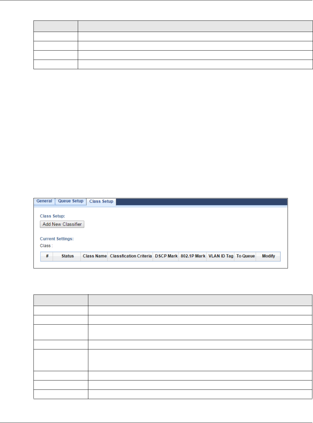
Chapter 20 Bandwidth Management
EMG3425-Q10A User’s Guide
138
20.5 The Class Setup Screen
Use this screen to add, edit or delete QoS classifiers. A classifier groups traffic into data flows
according to specific criteria such as the source address, destination address, source port number,
destination port number or incoming interface. For example, you can configure a classifier to select
traffic from the same protocol port (such as Telnet) to form a flow.
You can give different priorities to traffic that the EMG3425-Q10A forwards out through the WAN
interface. Give high priority to voice and video to make them run more smoothly. Similarly, give low
priority to many large file downloads so that they do not reduce the quality of other applications.
Click M a nagem e nt > Bandw idt h M GM T > Class Setup to open the following screen.
Figure 81 Management > Bandwidth MGMT > Class Setup
The following table describes the labels in this screen.
Rate Limit Specify the maximum transmission rate (in Kbps) allowed for traffic on this queue.
Back Click this to return to the previous screen.
Apply Click this to save your changes.
Cancel Click this to exit this screen without saving.
Table 58 Management > Bandwidth MGMT > Queue Setup: Add/Edit new queue
LABEL DESCRIPTION
Table 59 Management > Bandwidth MGMT > Class Setup
LABEL DESCRIPTION
Add new Classifier Click this to create a new classifier.
#This is the index number of the entry.
Status This field displays whether the classifier is active or not. A yellow bulb signifies that this
classifier is active. A gray bulb signifies that this classifier is not active.
Class Name This is the name of the classifier.
Classification
Criteria
This shows criteria specified in this classifier, for example the interface from which
traffic of this class should come and the source MAC address of traffic that matches this
classifier.
DSCP Mark This is the DSCP number added to traffic of this classifier.
802.1P Mark This is the IEEE 802.1p priority level assigned to traffic of this classifier.
VLAN ID Tag This is the VLAN ID number assigned to traffic of this classifier.
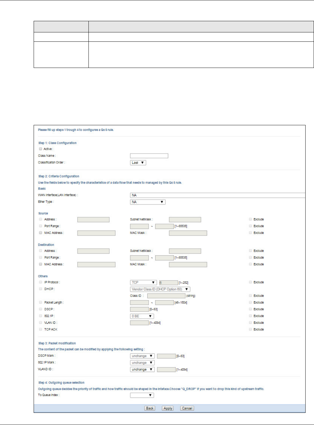
Chapter 20 Bandwidth Management
EMG3425-Q10A User’s Guide
139
20.5.1 Add/Edit a Classifier
Click Add N e w Classifie r in the Class Set u p screen or the Ed it icon next to a classifier to open
the following screen.
Figure 82 Management > Bandwidth MGMT > Class Setup: Add/Edit new class
To Que u e This is the name of the queue in which traffic of this classifier is put.
Modify Click the Ed it icon to edit the classifier.
Click the D e let e icon to delete an existing classifier. Note that subsequent rules move
up by one when you take this action.
Table 59 Management > Bandwidth MGMT > Class Setup (continued)
LABEL DESCRIPTION

Chapter 20 Bandwidth Management
EMG3425-Q10A User’s Guide
140
The following table describes the labels in this screen.
Table 60 Management > Bandwidth MGMT > Class Setup: Add/Edit new class
LABEL DESCRIPTION
Step 1: Class Configuration
Active Select this to enable this classifier.
Class Name Enter a descriptive name of up to 15 printable English keyboard characters, not including
spaces.
Classification
Order
Select an existing number for where you want to put this classifier to move the classifier to
the number you selected after clicking Apply.
Select La st to put this rule in the back of the classifier list.
Step 2: Criteria Configuration
Basic
WAN
interface(LAN
interface)
If you select From LAN in the Interface field, you can select specific interface(s) from which
traffic is received. ra0 ~ ra3 means wireless interfaces WLAN0 to WLAN3.
If you select Fr om W AN in the Interface field, you can select a specific WAN connection
(PVC0~PVC2) from which traffic is received.
Ether Type Select a predefined application to configure a class for the matched traffic.
If you select I P, you also need to configure source or destination MAC address, IP address,
DHCP options, DSCP value or the protocol type.
If you select ARP, you also need to configure source or destination MAC address.
If you select 8 0 2 .1 Q, you can configure an 802.1p priority level.
Source
Address Select the check box and enter the source IP address in dotted decimal notation. A blank
source IP address means any source IP address.
Subnet
Netmask Enter the source subnet mask.
Port Range If you select TCP or UD P in the I P Protocol field, select the check box and enter the port
number(s) of the source.
MAC
Address Select the check box and enter the source MAC address of the packet.
MAC Mask Type the mask for the specified MAC address to determine which bits a packet’s MAC
address should match.
Enter “f” for each bit of the specified source MAC address that the traffic’s MAC address
should match. Enter “0” for the bit(s) of the matched traffic’s MAC address, which can be of
any hexadecimal character(s). For example, if you set the MAC address to
00:13:49:00:00:00 and the mask to ff:ff:ff:00:00:00, a packet with a MAC address of
00:13:49:12:34:56 matches this criteria.
Exclude Select this option to exclude the packets that match the specified criteria from this classifier.
Destination
Address Select the check box and enter the source IP address in dotted decimal notation. A blank
source IP address means any source IP address.
Subnet
Netmask Enter the source subnet mask.
Port Range If you select TCP or UD P in the I P Protocol field, select the check box and enter the port
number(s) of the source.
MAC
Address Select the check box and enter the source MAC address of the packet.

Chapter 20 Bandwidth Management
EMG3425-Q10A User’s Guide
141
MAC Mask Type the mask for the specified MAC address to determine which bits a packet’s MAC
address should match.
Enter “f” for each bit of the specified source MAC address that the traffic’s MAC address
should match. Enter “0” for the bit(s) of the matched traffic’s MAC address, which can be of
any hexadecimal character(s). For example, if you set the MAC address to
00:13:49:00:00:00 and the mask to ff:ff:ff:00:00:00, a packet with a MAC address of
00:13:49:12:34:56 matches this criteria.
Exclude Select this option to exclude the packets that match the specified criteria from this classifier.
Others
IP Protocol This field is available only when you select I P in the Et h e r Type field.
Select this option and select the protocol (service type) from TCP, UDP, I CM P or I GMP. If
you select Use r def ined, enter the protocol (service type) number.
DHCP This field is available only when you select I P in the Et her Type field.
Select this option and select a DHCP option.
If you select Ve ndor Class I D ( D H CP Opt ion 6 0 ) , enter the Vendor Class Identifier
(Option 60) of the matched traffic, such as the type of the hardware or firmware.
If you select User Cla ss I D ( DHCP Opt ion 7 7 ) , enter a string that identifies the user’s
category or application type in the matched DHCP packets.
Packet
Length This field is available only when you select I P in the Et h e r Type field.
Select this option and enter the minimum and maximum packet length (from 46 to 1500) in
the fields provided.
DSCP This field is available only when you select I P in the Et her Type field.
Select this option and specify a DSCP (DiffServ Code Point) number between 0 and 63 in the
field provided.
802.1P This field is available only when you select 80 2 .1 Q in the Et h er Type field.
Select this option and select a priority level (between 0 and 7) from the drop-down list box.
"0" is the lowest priority level and "7" is the highest.
VLAN ID This field is available only when you select 8 0 2 .1 Q in the Ether Type field.
Select this option and specify a VLAN ID number.
TCP ACK This field is available only when you select I P in the Et her Type field.
If you select this option, the matched TCP packets must contain the ACK (Acknowledge)
flag.
Exclude Select this option to exclude the packets that match the specified criteria from this classifier.
Step 3: Packet modification
DSCP Mark This field is available only when you select I P in the Et her Type field.
If you select Mark, enter a DSCP value with which the EMG3425-Q10A replaces the DSCP
field in the packets.
If you select Uncha nge, the EMG3425-Q10A keep the DSCP field in the packets.
802.1P Mark Select a priority level with which the EMG3425-Q10A replaces the IEEE 802.1p priority field
in the packets.
If you select Uncha nge, the EMG3425-Q10A keep the 802.1p priority field in the packets.
Table 60 Management > Bandwidth MGMT > Class Setup: Add/Edit new class
LABEL DESCRIPTION
Chapter 20 Bandwidth Management
EMG3425-Q10A User’s Guide
142
20.6 Technical Reference
The following section contains additional technical information about the EMG3425-Q10A features
described in this chapter.
IEEE 802.1Q Tag
The IEEE 802.1Q standard defines an explicit VLAN tag in the MAC header to identify the VLAN
membership of a frame across bridges. A VLAN tag includes the 12-bit VLAN ID and 3-bit user
priority. The VLAN ID associates a frame with a specific VLAN and provides the information that
devices need to process the frame across the network.
IEEE 802.1p specifies the user priority field and defines up to eight separate traffic types. The
following table describes the traffic types defined in the IEEE 802.1d standard (which incorporates
the 802.1p).
VLAN ID If you select Rem ark , enter a VLAN ID number with which the EMG3425-Q10A replaces the
VLAN ID of the frames.
If you select Rem ove, the EMG3425-Q10A deletes the VLAN ID of the frames before
forwarding them out.
If you select Add, the EMG3425-Q10A treat all matched traffic untagged and add a second
VLAN ID.
If you select Uncha nge, the EMG3425-Q10A keep the VLAN ID in the packets.
Step 4: Outgoing queue selection
To Queue Index Select a queue that applies to this class.
You should have configured a queue in the Queue Se t up screen already.
Back Click this to return to the previous screen.
Apply Click this to save your changes.
Cancel Click this to exit this screen without saving.
Table 60 Management > Bandwidth MGMT > Class Setup: Add/Edit new class
LABEL DESCRIPTION
Table 61 IEEE 802.1p Priority Level and Traffic Type
PRIORITY
LEVEL TRAFFIC TYPE
Level 7 Typically used for network control traffic such as router configuration messages.
Level 6 Typically used for voice traffic that is especially sensitive to jitter (jitter is the variations in
delay).
Level 5 Typically used for video that consumes high bandwidth and is sensitive to jitter.
Level 4 Typically used for controlled load, latency-sensitive traffic such as SNA (Systems Network
Architecture) transactions.
Level 3 Typically used for “excellent effort” or better than best effort and would include important
business traffic that can tolerate some delay.
Level 2 This is for “spare bandwidth”.

Chapter 20 Bandwidth Management
EMG3425-Q10A User’s Guide
143
DiffServ
QoS is used to prioritize source-to-destination traffic flows. All packets in the flow are given the
same priority. You can use CoS (class of service) to give different priorities to different packet
types.
DiffServ (Differentiated Services) is a class of service (CoS) model that marks packets so that they
receive specific per-hop treatment at DiffServ-compliant network devices along the route based on
the application types and traffic flow. Packets are marked with DiffServ Code Points (DSCPs)
indicating the level of service desired. This allows the intermediary DiffServ-compliant network
devices to handle the packets differently depending on the code points without the need to
negotiate paths or remember state information for every flow. In addition, applications do not have
to request a particular service or give advanced notice of where the traffic is going.
DSCP and Per-Hop Behavior
DiffServ defines a new Differentiated Services (DS) field to replace the Type of Service (TOS) field
in the IP header. The DS field contains a 2-bit unused field and a 6-bit DSCP field which can define
up to 64 service levels. The following figure illustrates the DS field.
DSCP is backward compatible with the three precedence bits in the ToS octet so that non-DiffServ
compliant, ToS-enabled network device will not conflict with the DSCP mapping.
The DSCP value determines the forwarding behavior, the PHB (Per-Hop Behavior), that each packet
gets across the DiffServ network. Based on the marking rule, different kinds of traffic can be
marked for different kinds of forwarding. Resources can then be allocated according to the DSCP
values and the configured policies.
IP Precedence
Similar to IEEE 802.1p prioritization at layer-2, you can use IP precedence to prioritize packets in a
layer-3 network. IP precedence uses three bits of the eight-bit ToS (Type of Service) field in the IP
header. There are eight classes of services (ranging from zero to seven) in IP precedence. Zero is
the lowest priority level and seven is the highest.
Automatic Priority Queue Assignment
If you enable QoS on the EMG3425-Q10A, the EMG3425-Q10A can automatically base on the IEEE
802.1p priority level, IP precedence and/or packet length to assign priority to traffic which does not
match a class.
Level 1 This is typically used for non-critical “background” traffic such as bulk transfers that are
allowed but that should not affect other applications and users.
Level 0 Typically used for best-effort traffic.
DSCP (6 bits) Unused (2 bits)
Table 61 IEEE 802.1p Priority Level and Traffic Type
PRIORITY
LEVEL TRAFFIC TYPE

Chapter 20 Bandwidth Management
EMG3425-Q10A User’s Guide
144
The following table shows you the internal layer-2 and layer-3 QoS mapping on the EMG3425-
Q10A. On the EMG3425-Q10A, traffic assigned to higher priority queues gets through faster while
traffic in lower index queues is dropped if the network is congested.
Token Bucket
The token bucket algorithm uses tokens in a bucket to control when traffic can be transmitted. The
bucket stores tokens, each of which represents one byte. The algorithm allows bursts of up to b
bytes which is also the bucket size, so the bucket can hold up to b tokens. Tokens are generated
and added into the bucket at a constant rate. The following shows how tokens work with packets:
• A packet can be transmitted if the number of tokens in the bucket is equal to or greater than the
size of the packet (in bytes).
• After a packet is transmitted, a number of tokens corresponding to the packet size is removed
from the bucket.
Table 62 Internal Layer2 and Layer3 QoS Mapping
PRIORITY
QUEUE
LAYER 2 LAYER 3
IEEE 802.1P USER
PRIORITY
(ETHERNET
PRIORITY)
TOS (IP
PRECEDENCE) DSCP IP PACKET
LENGTH (BYTE)
0 1 0 000000
12
2 0 0 000000 >1100
3 3 1 001110
001100
001010
001000
250~1100
4 4 2 010110
010100
010010
010000
5 5 3 011110
011100
011010
011000
<250
6 6 4 100110
100100
100010
100000
5 101110
101000
7 7 6 110000
111000
7

Chapter 20 Bandwidth Management
EMG3425-Q10A User’s Guide
145
• If there are no tokens in the bucket, the EMG3425-Q10A stops transmitting until enough tokens
are generated.
• If not enough tokens are available, the EMG3425-Q10A treats the packet in either one of the
following ways:
In traffic shaping:
• Holds it in the queue until enough tokens are available in the bucket.
In traffic policing:
•Drops it.
• Transmits it but adds a DSCP mark. The EMG3425-Q10A may drop these marked packets if the
network is overloaded.
Configure the bucket size to be equal to or less than the amount of the bandwidth that the interface
can support. It does not help if you set it to a bucket size over the interface’s capability. The smaller
the bucket size, the lower the data transmission rate and that may cause outgoing packets to be
dropped. A larger transmission rate requires a big bucket size. For example, use a bucket size of 10
kbytes to get the transmission rate up to 10 Mbps.
Single Rate Three Color Marker
The Single Rate Three Color Marker (srTCM, defined in RFC 2697) is a type of traffic policing that
identifies packets by comparing them to one user-defined rate, the Committed Information Rate
(CIR), and two burst sizes: the Committed Burst Size (CBS) and Excess Burst Size (EBS).
The srTCM evaluates incoming packets and marks them with one of three colors which refer to
packet loss priority levels. High packet loss priority level is referred to as red, medium is referred to
as yellow and low is referred to as green.
The srTCM is based on the token bucket filter and has two token buckets (CBS and EBS). Tokens
are generated and added into the bucket at a constant rate, called Committed Information Rate
(CIR). When the first bucket (CBS) is full, new tokens overflow into the second bucket (EBS).
All packets are evaluated against the CBS. If a packet does not exceed the CBS it is marked green.
Otherwise it is evaluated against the EBS. If it is below the EBS then it is marked yellow. If it
exceeds the EBS then it is marked red.
The following shows how tokens work with incoming packets in srTCM:
• A packet arrives. The packet is marked green and can be transmitted if the number of tokens in
the CBS bucket is equal to or greater than the size of the packet (in bytes).
• After a packet is transmitted, a number of tokens corresponding to the packet size is removed
from the CBS bucket.
• If there are not enough tokens in the CBS bucket, the EMG3425-Q10A checks the EBS bucket.
The packet is marked yellow if there are sufficient tokens in the EBS bucket. Otherwise, the
packet is marked red. No tokens are removed if the packet is dropped.
Two Rate Three Color Marker
The Two Rate Three Color Marker (trTCM, defined in RFC 2698) is a type of traffic policing that
identifies packets by comparing them to two user-defined rates: the Committed Information Rate
(CIR) and the Peak Information Rate (PIR). The CIR specifies the average rate at which packets are
admitted to the network. The PIR is greater than or equal to the CIR. CIR and PIR values are based

Chapter 20 Bandwidth Management
EMG3425-Q10A User’s Guide
146
on the guaranteed and maximum bandwidth respectively as negotiated between a service provider
and client.
The trTCM evaluates incoming packets and marks them with one of three colors which refer to
packet loss priority levels. High packet loss priority level is referred to as red, medium is referred to
as yellow and low is referred to as green.
The trTCM is based on the token bucket filter and has two token buckets (Committed Burst Size
(CBS) and Peak Burst Size (PBS)). Tokens are generated and added into the two buckets at the CIR
and PIR respectively.
All packets are evaluated against the PIR. If a packet exceeds the PIR it is marked red. Otherwise it
is evaluated against the CIR. If it exceeds the CIR then it is marked yellow. Finally, if it is below the
CIR then it is marked green.
The following shows how tokens work with incoming packets in trTCM:
• A packet arrives. If the number of tokens in the PBS bucket is less than the size of the packet (in
bytes), the packet is marked red and may be dropped regardless of the CBS bucket. No tokens
are removed if the packet is dropped.
• If the PBS bucket has enough tokens, the EMG3425-Q10A checks the CBS bucket. The packet is
marked green and can be transmitted if the number of tokens in the CBS bucket is equal to or
greater than the size of the packet (in bytes). Otherwise, the packet is marked yellow.

EMG3425-Q10A User’s Guide
147
CHAPTER 21
Remote Management
21.1 Overview
This chapter provides information on the Remote Management screens.
Remote Management allows you to manage your EMG3425-Q10A from a remote location through
the following interfaces:
•LAN and WAN
•LAN only
•WAN only
Note: The EMG3425-Q10A is managed using the Web Configurator.
21.2 What You Can Do in this Chapter
•Use the WWW screen to define the interface/s from which the EMG3425-Q10A can be managed
remotely using the web and specify a secure client that can manage the EMG3425-Q10A (Section
21.4 on page 148).
•Use the Te lnet screen to define the interface/s from which the EMG3425-Q10A can be managed
remotely using Telnet service and specify a secure client that can manage the EMG3425-Q10A
(Section 21.5 on page 151).
• Your EMG3425-Q10A can act as an SNMP agent, which allows a manager station to manage and
monitor the EMG3425-Q10A through the network. Use the SN M P screen to configure SNMP
settings. You can also specify from which IP addresses the access can come (Section 21.6 on
page 152).
•Use the W a k e On LAN screen to enable Wake on LAN and remotely turn on a device on the local
network (Section 21.7 on page 154).
•Use the TR0 6 9 screen to configure the EMG3425-Q10A’s TR-069 auto-configuration settings and
import CA certificates to the EMG3425-Q10A (Section 21.8 on page 155).
21.3 What You Need to Know
Remote management over LAN or WAN will not work when:
1The IP address in the Secured Clie n t I P Addre ss field (Section 21.4 on page 148) does not match
the client IP address. If it does not match, the EMG3425-Q10A will disconnect the session
immediately.

Chapter 21 Remote Management
EMG3425-Q10A User’s Guide
148
2There is already another remote management session. You may only have one remote
management session running at one time.
3There is a firewall rule that blocks it.
21.3.1 Remote Management and NAT
When NAT is enabled:
• Use the EMG3425-Q10A’s WAN IP address when configuring from the WAN.
• Use the EMG3425-Q10A’s LAN IP address when configuring from the LAN.
21.3.2 System Timeout
There is a default system management idle timeout of five minutes (three hundred seconds). The
EMG3425-Q10A automatically logs you out if the management session remains idle for longer than
this timeout period. The management session does not time out when a statistics screen is polling.
You can change the timeout period in the M aint enance > Gener a l screen
21.4 WWW Screen
To change your EMG3425-Q10A’s remote management settings, click Configur a tion >
Ma n a gem e n t > Rem ot e MGM T to open the W W W screen.
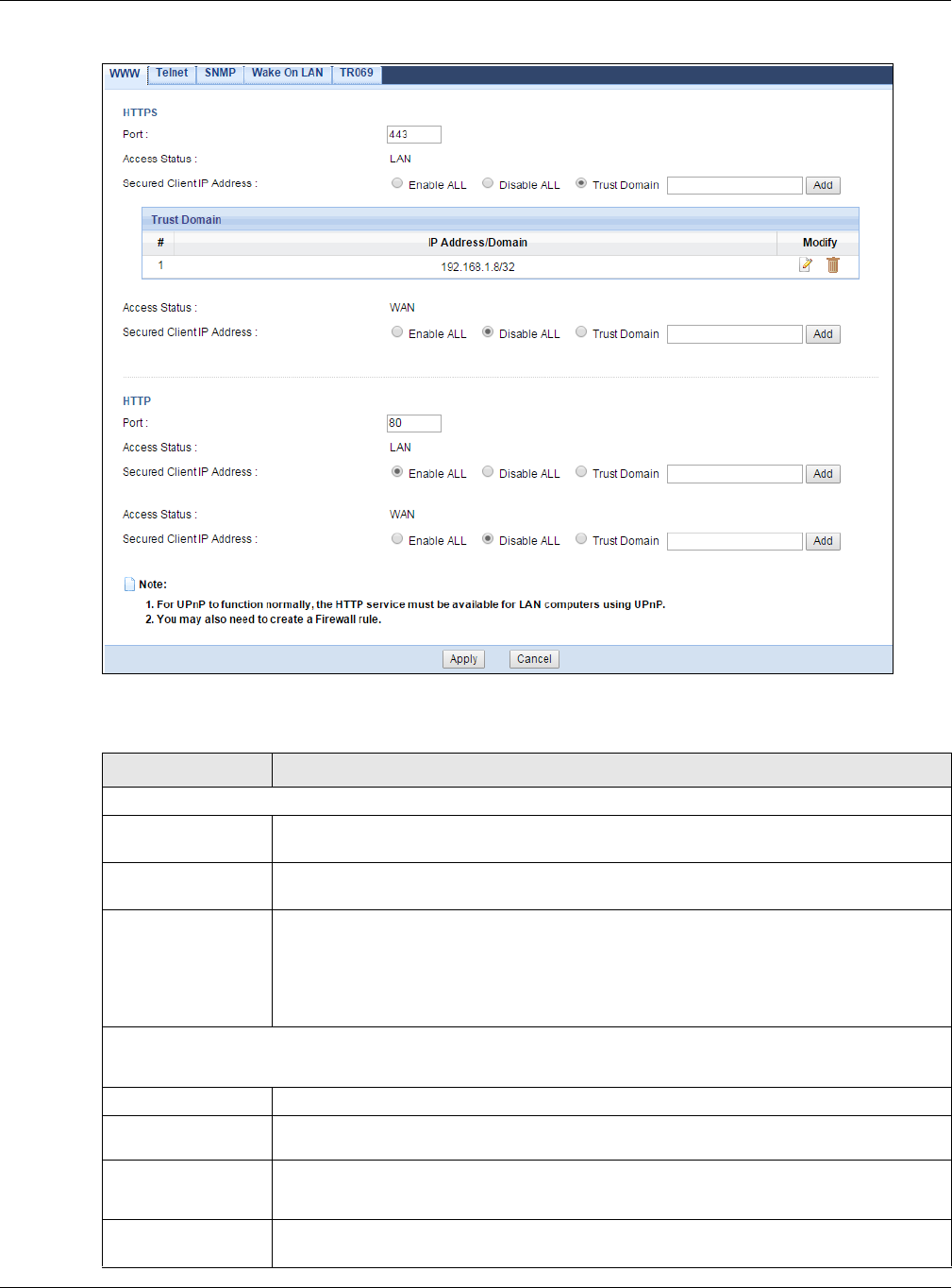
Chapter 21 Remote Management
EMG3425-Q10A User’s Guide
149
Figure 83 Configuration > Management > Remote MGMT > WWW
The following table describes the labels in this screen.
Table 63 Configuration > Management > Remote MGMT > WWW
LABEL DESCRIPTION
HTTPS
Port You may change the server port number for a HTTPS service if needed. However you
must use the same port number in order to use that service for remote management.
Access Status This field displays the interface through which a computer may access the EMG3425-
Q10A using this service.
Secured Client IP
Address
Select Enable ALL to allow all computers to access the EMG3425-Q10A using the
HTTPS service. Otherwise, select Disa ble ALL.
Or you can select Trust D om ain to specify the IP address/domain of the computer that
can access the EMG3425-Q10A. Click Add to add the IP address/domain to the trust
domain.
Trust Domain
This is available only when you select Trust Dom ain in the Se cured Client I P Address field.
#This displays the index number of the trust domain.
IP Address/
Domain This field displays the IP address/domain.
Modify Click the Ed it icon to go to the screen where you can edit the IP address/domain.
Click the D e let e icon to delete an existing IP address/domain.
Access Status This field displays the interface through which a computer may access the EMG3425-
Q10A using this service.

Chapter 21 Remote Management
EMG3425-Q10A User’s Guide
150
Secured Client IP
Address
Select Enable ALL to allow all computers to access the EMG3425-Q10A using the
HTTPS service. Otherwise, select Disa ble ALL.
Or you can select Trust D om ain to specify the IP address/domain of the computer that
can access the EMG3425-Q10A. Click Add to add the IP address/domain to the trust
domain.
Trust Domain
This is available only when you select Trust Dom ain in the Se cured Client I P Address field.
#This displays the index number of the trust domain.
IP Address/
Domain This field displays the IP address/domain.
Modify Click the Ed it icon to go to the screen where you can edit the IP address/domain.
Click the D e let e icon to delete an existing IP address/domain.
HTTP
Port You may change the server port number for a HTTP service if needed. However you
must use the same port number in order to use that service for remote management.
Access Status This field displays the interface through which a computer may access the EMG3425-
Q10A using this service.
Secured Client IP
Address
Select Enable ALL to allow all computers to access the EMG3425-Q10A using the
HTTPS service. Otherwise, select Disa ble ALL.
Or you can select Trust D om ain to specify the IP address/domain of the computer that
can access the EMG3425-Q10A. Click Add to add the IP address/domain to the trust
domain.
Trust Domain
This is available only when you select Trust Dom ain in the Se cured Client I P Address field.
#This displays the index number of the trust domain.
IP Address/
Domain This field displays the IP address/domain.
Modify Click the Ed it icon to go to the screen where you can edit the IP address/domain.
Click the D e let e icon to delete an existing IP address/domain.
Access Status This field displays the interface through which a computer may access the EMG3425-
Q10A using this service.
Secured Client IP
Address
Select Enable ALL to allow all computers to access the EMG3425-Q10A using the
HTTPS service. Otherwise, select Disa ble ALL.
Or you can select Trust D om ain to specify the IP address/domain of the computer that
can access the EMG3425-Q10A. Click Add to add the IP address/domain to the trust
domain.
Trust Domain
This is available only when you select Trust Dom ain in the Se cured Client I P Address field.
#This displays the index number of the trust domain.
IP Address/
Domain This field displays the IP address/domain.
Modify Click the Ed it icon to go to the screen where you can edit the IP address/domain.
Click the D e let e icon to delete an existing IP address/domain.
Apply Click Apply to save your customized settings and exit this screen.
Cancel Click Cancel to exit this screen without saving.
Table 63 Configuration > Management > Remote MGMT > WWW (continued)
LABEL DESCRIPTION
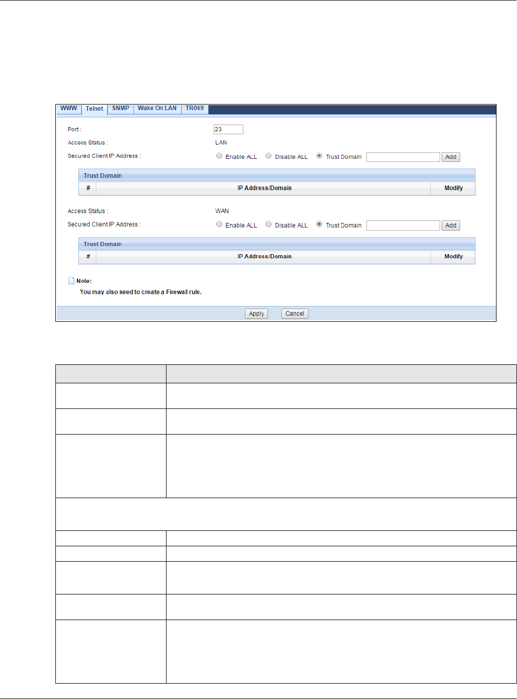
Chapter 21 Remote Management
EMG3425-Q10A User’s Guide
151
21.5 Telnet Screen
To change your EMG3425-Q10A’s remote management settings, click Ma n a gem ent > Re m ot e
MGMT > Te lnet to open the Telnet screen.
Figure 84 Configuration> Management > Remote MGMT > Telnet
The following table describes the labels in this screen.
Table 64 Configuration > Management > Remote MGMT > Telnet
LABEL DESCRIPTION
Port You may change the server port number for a service if needed, however you must
use the same port number in order to use that service for remote management.
Access Status This field displays the interface through which a computer may access the
EMG3425-Q10A using this service.
Secured Client IP
Address
Select Enable ALL to allow all computers to access the EMG3425-Q10A using the
HTTPS service. Otherwise, select Disa ble ALL.
Or you can select Trust D om ain to specify the IP address/domain of the computer
that can access the EMG3425-Q10A. Click Add to add the IP address/domain to
the trust domain.
Trust Domain
This is available only when you select Trust Dom ain in the Se cured Client I P Address field.
#This displays the index number of the trust domain.
IP Address/Domain This field displays the IP address/domain.
Modify Click the Ed it icon to go to the screen where you can edit the IP address/domain.
Click the D e let e icon to delete an existing IP address/domain.
Access Status This field displays the interface through which a computer may access the
EMG3425-Q10A using this service.
Secured Client IP
Address
Select Enable ALL to allow all computers to access the EMG3425-Q10A using the
HTTPS service. Otherwise, select Disa ble ALL.
Or you can select Trust D om ain to specify the IP address/domain of the computer
that can access the EMG3425-Q10A. Click Add to add the IP address/domain to
the trust domain.
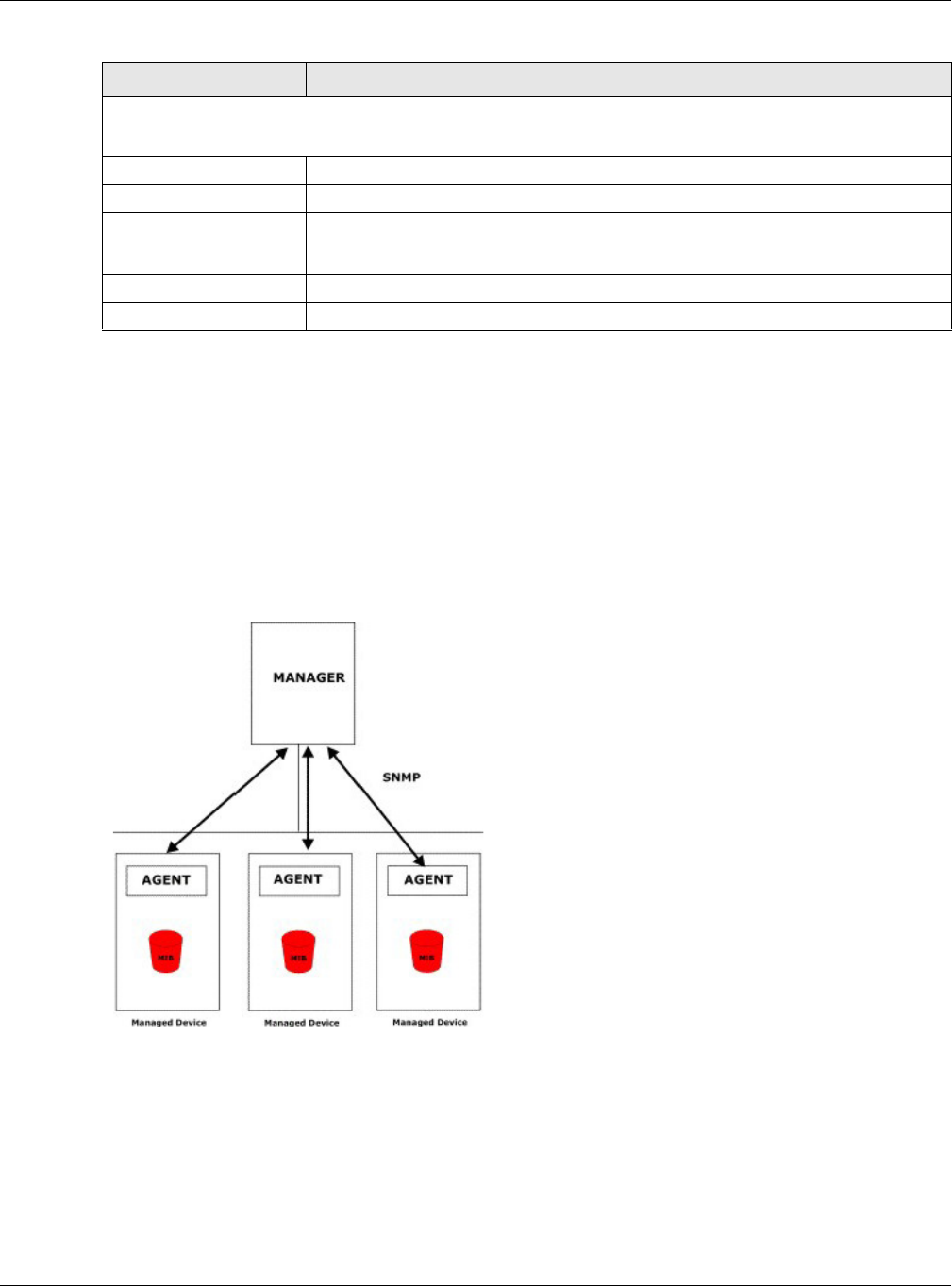
Chapter 21 Remote Management
EMG3425-Q10A User’s Guide
152
21.6 SNMP Screen
Simple Network Management Protocol is a protocol used for exchanging management information
between network devices. Your EMG3425-Q10A supports SNMP agent functionality, which allows a
manager station to manage and monitor the EMG3425-Q10A through the network. The EMG3425-
Q10A supports SNMP version one (SNMPv1) and version two (SNMPv2c). The next figure illustrates
an SNMP management operation.
Figure 85 SNMP Management Model
An SNMP managed network consists of two main types of component: agents and a manager.
An agent is a management software module that resides in a managed device (the EMG3425-
Q10A). An agent translates the local management information from the managed device into a
form compatible with SNMP. The manager is the console through which network administrators
perform network management functions. It executes applications that control and monitor
managed devices.
Trust Domain
This is available only when you select Trust Dom ain in the Se cured Client I P Address field.
#This displays the index number of the trust domain.
IP Address/Domain This field displays the IP address/domain.
Modify Click the Ed it icon to go to the screen where you can edit the IP address/domain.
Click the D e let e icon to delete an existing IP address/domain.
Apply Click Apply to save your customized settings.
Cancel Click Cancel to begin configuring this screen afresh.
Table 64 Configuration > Management > Remote MGMT > Telnet (continued)
LABEL DESCRIPTION
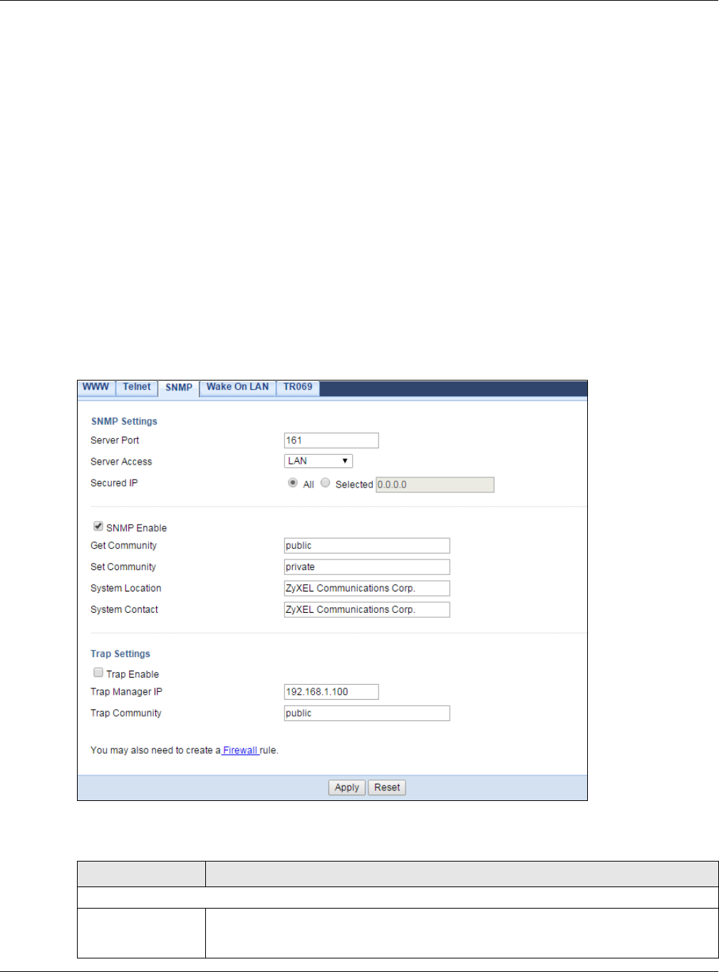
Chapter 21 Remote Management
EMG3425-Q10A User’s Guide
153
The managed devices contain object variables/managed objects that define each piece of
information to be collected about a device. Examples of variables include such as number of
packets received, node port status etc. A Management Information Base (MIB) is a collection of
managed objects. SNMP allows a manager and agents to communicate for the purpose of accessing
these objects.
SNMP itself is a simple request/response protocol based on the manager/agent model. The
manager issues a request and the agent returns responses using the following protocol operations:
• Get - Allows the manager to retrieve an object variable from the agent.
• GetNext - Allows the manager to retrieve the next object variable from a table or list within an
agent. In SNMPv1, when a manager wants to retrieve all elements of a table from an agent, it
initiates a Get operation, followed by a series of GetNext operations.
• Set - Allows the manager to set values for object variables within an agent.
• Trap - Used by the agent to inform the manager of some events.
To change your EMG3425-Q10A’s SNMP settings, click Con figura t ion > Ma nagem e nt > Rem ote
MGMT > SN M P to display the screen as shown.
Figure 86 Configuration > Management > Remote MGMT > SNMP
The following table describes the labels in this screen.
Table 65 Configuration > Management > Remote MGMT > SNMP
LABEL DESCRIPTION
SNMP Settings
Server Port The SNMP agent listens on port 161 by default. If you change the SNMP server port to a
different number on the EMG3425-Q10A, for example 8161, then you must notify
people who need to access the EMG3425-Q10A SNMP agent to use the same port.
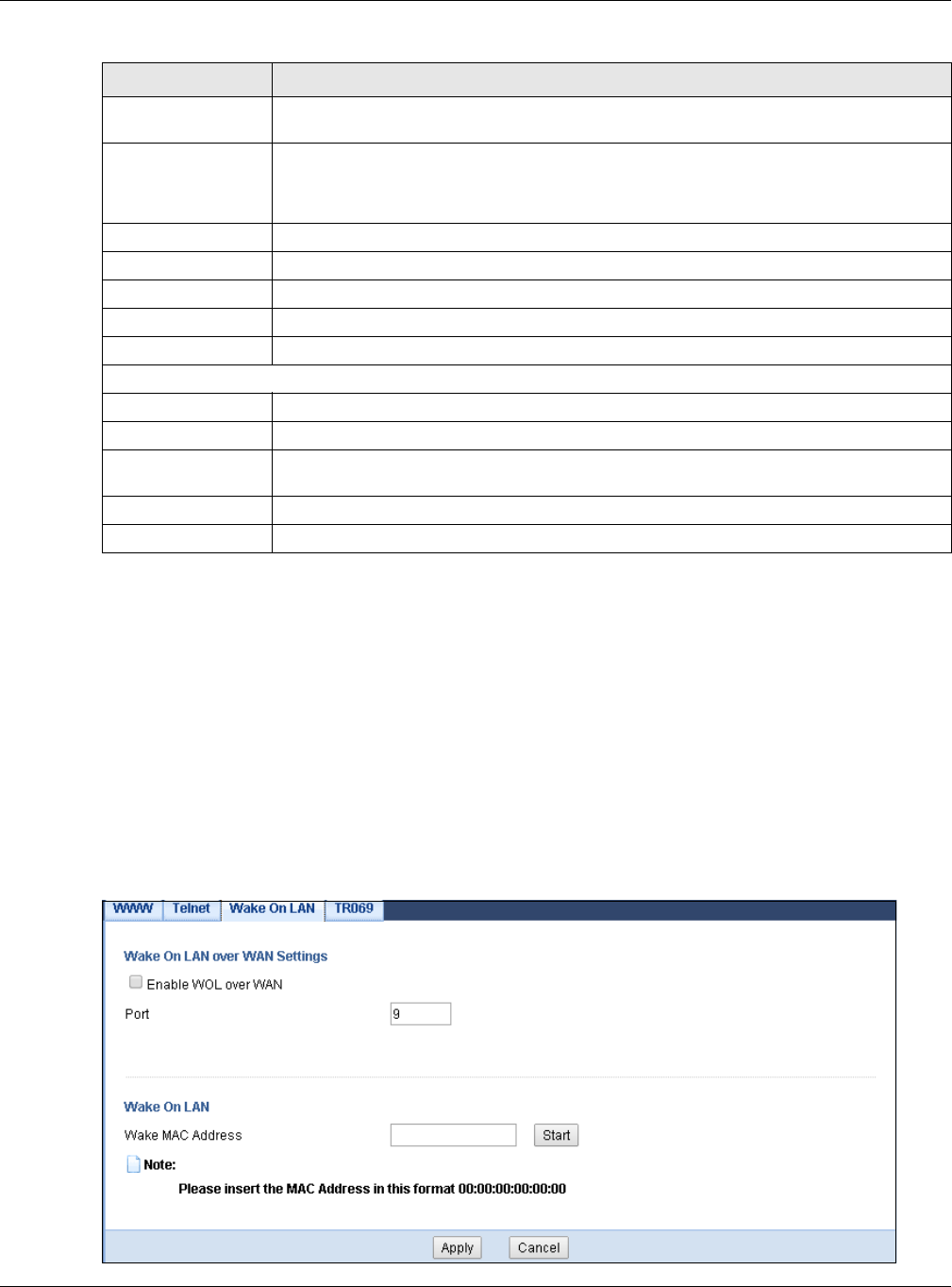
Chapter 21 Remote Management
EMG3425-Q10A User’s Guide
154
21.7 Wake On LAN Screen
Wake On LAN (WoL) allows you to remotely turn on a device on the network, such as a computer,
storage device or media server. To use this feature the remote hardware (for example the network
adapter on a computer) must support Wake On LAN using the “Magic Packet” method.
You need to know the MAC address of the remote device. It may be on a label on the device.
Use this screen to remotely turn on a device on the network. Click the Con figur at ion >
Ma n a gem e n t > Rem ote M GMT > W a ke On LAN to open the following screen.
Figure 87 Configuration > Management > Remote MGMT > Wake On LAN
Server Access Select the interface(s) through which a computer may access the EMG3425-Q10A using
this service.
Secured Ip Select All to allow all computers to access the EMG3425-Q10A.
Otherwise, check Sele ct ed and specify the IP address of the computer that can access
the EMG3425-Q10A.
SNMP Enable Select this to enable SNMP on this device.
Get Community Enter the SNMP get community information here.
Set Community Enter the SNMP set community information here.
System Location Enter the SNMP system location.
System Contact Enter the SNMP system contact.
Trap Settings
Trap Enable Select this to enable trap settings on this device.
Trap Manager IP Type the IP address of the station to send your SNMP traps to.
Trap Community Type the trap community, which is the password sent with each trap to the SNMP
manager. The default is public and allows all requests.
Apply Click Apply to save your customized settings and exit this screen.
Reset Click Re se t to begin configuring this screen afresh.
Table 65 Configuration > Management > Remote MGMT > SNMP (continued)
LABEL DESCRIPTION

Chapter 21 Remote Management
EMG3425-Q10A User’s Guide
155
The following table describes the labels in this screen.
21.8 TR069 Screen
TR-069 defines how Customer Premise Equipment (CPE), for example your ZyXEL Device, can be
managed over the WAN by an Auto Configuration Server (ACS). TR-069 is based on sending
Remote Procedure Calls (RPCs) between an ACS and a client device. RPCs are sent in Extensible
Markup Language (XML) format over HTTP or HTTPS.
An administrator can use an ACS to remotely set up the EMG3425-Q10A, modify settings, perform
firmware upgrades as well as monitor and diagnose the EMG3425-Q10A. You have to enable the
device to be managed by the ACS and specify the ACS IP address or domain name and username
and password.
Click Con figura t ion > M a na g e m e n t > Rem ote M GM T > TR0 6 9 to display the screen as shown.
Use this screen to configure your EMG3425-Q10A to be managed by an ACS.
Table 66 Configuration > Management > Remote MGMT > Wake On LAN
LABEL DESCRIPTION
Wake On LAN over WAN
Settings
Enable WOL over WAN Select this option to have the EMG3425-Q10A forward a WoL “Magic Packet” to
all devices on the LAN if the packet comes from the WAN or remote network
and uses the port number specified in the Por t field. A LAN device whose
hardware supports Wake on LAN then will be powered on if it is turned off
previously.
Port Type a port number from which a WoL packet is forwarded to the LAN.
Wake On LAN
Wake MAC Address Enter the MAC Address of the device on the network that will be turned on.
A MAC address consists of six hexadecimal character pairs.
Start Click this to have the EMG3425-Q10A generate a WoL packet and forward it to
turn the specified device on.
A screen pops up displaying MAC address error if you input the MAC address
incorrectly.
Apply Click Apply to save the setting to the EMG3425-Q10A.
Cancel Click Cancel to begin configuring this screen afresh.
Chapter 21 Remote Management
EMG3425-Q10A User’s Guide
156
Figure 88 Configuration > Management > Remote MGMT > TR069
The following table describes the labels in this screen.
Table 67 Configuration > Management > Remote MGMT > TR069
LABEL DESCRIPTION
Inform Select En able for the EMG3425-Q10A to send periodic inform via TR-069 on the WAN.
Otherwise, select Disable .
Inform Interval Enter the time interval (in seconds) at which the EMG3425-Q10A sends information to
the auto-configuration server.
Inform Source Select SN or M AC for the EMG3425-Q10A to be the source of information via TR-069
on the WAN.
ACS URL Enter the URL or IP address of the auto-configuration server.
ACS Username Enter the TR-069 user name for authentication with the auto-configuration server.
ACS Password Enter the TR-069 password for authentication with the auto-configuration server.
Connection Request
Port
Enter the connection request port number.
When the ACS makes a connection request to the EMG3425-Q10A, this port number is
used to authenticate the ACS.
Connection Request
Username
Enter the connection request user name.
When the ACS makes a connection request to the EMG3425-Q10A, this user name is
used to authenticate the ACS.
Connection Request
Password
Enter the connection request password.
When the ACS makes a connection request to the EMG3425-Q10A, this password is
used to authenticate the ACS.
Interface This is the interface of the connection.
Upload Certificate The EMG3425-Q10A can use certificates (also called digital IDs) to authenticate users.
Certificates are based on public-private key pairs. A certificate contains the certificate
owner’s identity and public key.

Chapter 21 Remote Management
EMG3425-Q10A User’s Guide
157
File Path Type in the location of the certificate you want to upload in this field or click Choose
File to find it.
Choose File Click Ch oose File to find the certificate you want to upload.
You cannot import a certificate with the same name as a certificate that is already in
the EMG3425-Q10A.
Upload Click Upload to begin the upload process.
Apply Click Apply to save your customized settings and exit this screen.
Cancel Click Cancel to exit this screen without saving.
Table 67 Configuration > Management > Remote MGMT > TR069 (continued)
LABEL DESCRIPTION

EMG3425-Q10A User’s Guide
158
CHAPTER 22
Universal Plug-and-Play (UPnP)
22.1 Overview
This chapter introduces the UPnP feature in the web configurator.
Universal Plug and Play (UPnP) is a distributed, open networking standard that uses TCP/IP for
simple peer-to-peer network connectivity between devices. A UPnP device can dynamically join a
network, obtain an IP address, convey its capabilities and learn about other devices on the network.
In turn, a device can leave a network smoothly and automatically when it is no longer in use.
22.2 What You Need to Know
UPnP hardware is identified as an icon in the Network Connections folder (Windows XP). Each UPnP
compatible device installed on your network will appear as a separate icon. Selecting the icon of a
UPnP device will allow you to access the information and properties of that device.
22.2.1 NAT Traversal
UPnP NAT traversal automates the process of allowing an application to operate through NAT. UPnP
network devices can automatically configure network addressing, announce their presence in the
network to other UPnP devices and enable exchange of simple product and service descriptions.
NAT traversal allows the following:
• Dynamic port mapping
• Learning public IP addresses
• Assigning lease times to mappings
Windows Messenger is an example of an application that supports NAT traversal and UPnP.
See the NAT chapter for more information on NAT.
22.2.2 Cautions with UPnP
The automated nature of NAT traversal applications in establishing their own services and opening
firewall ports may present network security issues. Network information and configuration may also
be obtained and modified by users in some network environments.
When a UPnP device joins a network, it announces its presence with a multicast message. For
security reasons, the EMG3425-Q10A allows multicast messages on the LAN only.
Chapter 22 Universal Plug-and-Play (UPnP)
EMG3425-Q10A User’s Guide
159
All UPnP-enabled devices may communicate freely with each other without additional configuration.
Disable UPnP if this is not your intention.
22.3 UPnP Screen
Use this screen to enable UPnP on your EMG3425-Q10A.
Click M a nagem e nt > UPn P to display the screen shown next.
Figure 89 Management > UPnP
The following table describes the fields in this screen.
22.4 Technical Reference
The sections show examples of using UPnP.
22.4.1 Using UPnP in Windows XP Example
This section shows you how to use the UPnP feature in Windows XP. You must already have UPnP
installed in Windows XP and UPnP activated on the EMG3425-Q10A.
Make sure the computer is connected to a LAN port of the EMG3425-Q10A. Turn on your computer
and the EMG3425-Q10A.
22.4.1.1 Auto-discover Your UPnP-enabled Network Device
1Click st a r t and Cont r ol Pane l. Double-click Net w or k Connections. An icon displays under
Internet Gateway.
2Right-click the icon and select Pr ope rt ie s.
Table 68 Management > UPnP
LABEL DESCRIPTION
UPnP Select Enable to activate UPnP. Be aware that anyone could use a UPnP application to
open the web configurator's login screen without entering the EMG3425-Q10A's IP
address (although you must still enter the password to access the web configurator).
Apply Click Apply to save the setting to the EMG3425-Q10A.
Cancel Click Cancel to return to the previously saved settings.
Chapter 22 Universal Plug-and-Play (UPnP)
EMG3425-Q10A User’s Guide
160
Figure 90 Network Connections
3In the I nter n e t Connection Pr operties window, click Se t t ings to see the port mappings there
were automatically created.
Figure 91 Internet Connection Properties
4You may edit or delete the port mappings or click Add to manually add port mappings.
Figure 92 Internet Connection Properties: Advanced Settings
Chapter 22 Universal Plug-and-Play (UPnP)
EMG3425-Q10A User’s Guide
161
Figure 93 Internet Connection Properties: Advanced Settings: Add
Note: When the UPnP-enabled device is disconnected from your computer, all port
mappings will be deleted automatically.
5Select Show icon in notificat ion area w hen connected option and click OK. An icon displays in
the system tray.
Figure 94 System Tray Icon
6Double-click on the icon to display your current Internet connection status.
Figure 95 Internet Connection Status
22.4.2 Web Configurator Easy Access
With UPnP, you can access the web-based configurator on the EMG3425-Q10A without finding out
the IP address of the EMG3425-Q10A first. This comes helpful if you do not know the IP address of
the EMG3425-Q10A.
Follow the steps below to access the web configurator.
1Click St a r t and then Cont rol Pa nel.
2Double-click N e t w ork Connections.
Chapter 22 Universal Plug-and-Play (UPnP)
EMG3425-Q10A User’s Guide
162
3Select M y Net w or k Places under Other Places.
Figure 96 Network Connections
4An icon with the description for each UPnP-enabled device displays under Local Net w or k .
5Right-click on the icon for your EMG3425-Q10A and select I nvok e. The web configurator login
screen displays.
Figure 97 Network Connections: My Network Places
6Right-click on the icon for your EMG3425-Q10A and select Prop ert ie s. A properties window
displays with basic information about the EMG3425-Q10A.
Chapter 22 Universal Plug-and-Play (UPnP)
EMG3425-Q10A User’s Guide
163
Figure 98 Network Connections: My Network Places: Properties: Example
EMG3425-Q10A User’s Guide
164
CHAPTER 23
USB Media Sharing
23.1 Overview
This chapter describes how to configure the media sharing settings on the EMG3425-Q10A.
Note: The read and write performance may be affected by amount of file-sharing traffic
on your network, type of connected USB device and your USB version (1.1 or 2.0).
Media Server
You can set up your EMG3425-Q10A to act as a media server to provide media (like video) to DLNA-
compliant players, such as Windows Media Player, ZyXEL DMAs (Digital Media Adapters), Xboxes or
PS3s. The media server and clients must have IP addresses in the same subnet.
The EMG3425-Q10A media server enables you to:
• Publish all folders for everyone to play media files in the USB storage device connected to the
EMG3425-Q10A.
• Use hardware-based media clients like the DMA-2500 to play the files.
Note: Anyone on your network can play the media files in the published folders. No user
name and password nor other form of security is required.
The following figure is an overview of the EMG3425-Q10A’s media server feature. DLNA devices A
and B can access and play files on a USB device (C) which is connected to the EMG3425-Q10A (D).
Figure 99 Media Server Overview
A
B
C
D
Chapter 23 USB Media Sharing
EMG3425-Q10A User’s Guide
165
File-Sharing Server
You can also share files on a USB memory stick or hard drive connected to your EMG3425-Q10A
with users on your network.
The following figure is an overview of the EMG3425-Q10A’s file-sharing server feature. Computers
A and B can access files on a USB device (C) which is connected to the EMG3425-Q10A (D).
Figure 100 File Sharing Overview
23.2 What You Can Do
•Use the DLN A screen to use the EMG3425-Q10A as a media server and allow DLNA-compliant
devices to play media files stored in the attached USB device (Section 23.5 on page 167).
•Use the SAMBA screen to enable file-sharing via the EMG3425-Q10A using Windows Explorer or
the workgroup name. This screen also allow you to configure the workgroup name and create
user accounts (Section 23.6 on page 167).
•Use the FTP screen to allow file sharing via the EMG3425-Q10A using FTP and create user
accounts (Section 23.7 on page 169).
23.3 What You Need To Know
DLNA
The Digital Living Network Alliance (DLNA) is a group of personal computer and electronics
companies that works to make products compatible in a home network. DLNA clients play files
stored on DLNA servers. The EMG3425-Q10A can function as a DLNA-compliant media server and
stream files to DLNA-compliant media clients without any configuration.
A
BC
D

Chapter 23 USB Media Sharing
EMG3425-Q10A User’s Guide
166
Workgroup name
This is the name given to a set of computers that are connected on a network and share resources
such as a printer or files. Windows automatically assigns the workgroup name when you set up a
network.
File Systems
A file system is a way of storing and organizing files on your hard drive and storage device. Often
different operating systems such as Windows or Linux have different file systems. The file-sharing
feature on your EMG3425-Q10A supports New Technology File System (NTFS), File Allocation Table
(FAT) and FAT32 file systems.
Windows/CIFS
Common Internet File System (CIFS) is a standard protocol supported by most operating systems
in order to share files across the network.
CIFS runs over TCP/IP but uses the SMB (Server Message Block) protocol found in Microsoft
Windows for file and printer access; therefore, CIFS will allow all applications, not just Web
browsers, to open and share files across the Internet.
The EMG3425-Q10A uses Common Internet File System (CIFS) protocol for its file sharing
functions. CIFS compatible computers can access the USB file storage devices connected to the
EMG3425-Q10A. CIFS protocol is supported on Microsoft Windows, Linux Samba and other
operating systems (refer to your systems specifications for CIFS compatibility).
Samba
SMB is a client-server protocol used by Microsoft Windows systems for sharing files, printers, and
so on.
Samba is a free SMB server that runs on most Unix and Unix-like systems. It provides an
implementation of an SMB client and server for use with non-Microsoft operating systems.
File Transfer Protocol
This is a method of transferring data from one computer to another over a network such as the
Internet.
23.4 Before You Begin
Make sure the EMG3425-Q10A is connected to your network and turned on.
1Connect the USB device to one of the EMG3425-Q10A’s USB ports.
2The EMG3425-Q10A detects the USB device and makes its contents available for browsing. If you
are connecting a USB hard drive that comes with an external power supply, make sure it is
connected to an appropriate power source that is on.

Chapter 23 USB Media Sharing
EMG3425-Q10A User’s Guide
167
Note: If your USB device cannot be detected by the EMG3425-Q10A, see the
troubleshooting for suggestions.
23.5 DLNA Screen
Use this screen to have the EMG3425-Q10A act as a DLNA-compliant media server that lets DLNA-
compliant media clients on your network play video, music, and photos from the EMG3425-Q10A
(without having to copy them to another computer). Click Mana gem e nt > USB Media Sh a rin g >
D LN A.
Figure 101 Management > USB Media Sharing > DLNA
The following table describes the labels in this screen.
23.6 SAMBA Screen
Use this screen to set up file-sharing via the EMG3425-Q10A using Windows Explorer or the
workgroup name. You can also configure the workgroup name and create file-sharing user
accounts. Click M a nagem e n t > USB Media Sha r ing > SAMBA.
Table 69 Management > USB Media Sharing > DLNA
LABEL DESCRIPTION
Enable DLNA Select this to have the EMG3425-Q10A function as a DLNA-compliant media server.
USB1/2 Select the media type that you want to share on the USB device connected to the
EMG3425-Q10A’s USB port.
Rescan Click this button to have the EMG3425-Q10A scan the media files on the connected USB
device and do indexing of the file list again so that DLNA clients can find the new files if
any.
Apply Click Apply to save your changes back to the EMG3425-Q10A.
Cancel Click Cancel to begin configuring this screen afresh.
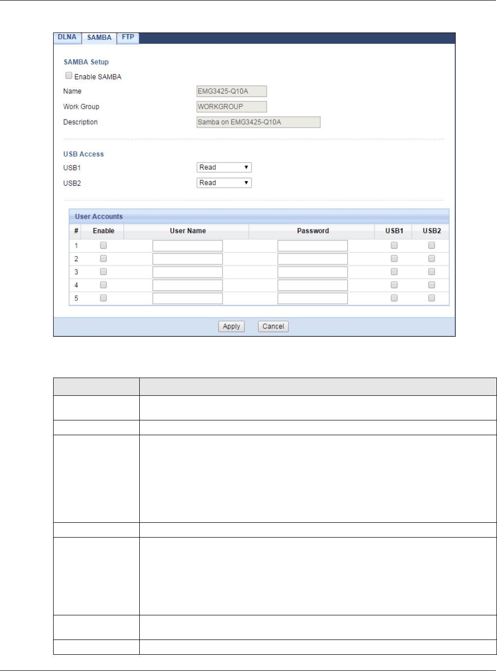
Chapter 23 USB Media Sharing
EMG3425-Q10A User’s Guide
168
Figure 102 Management > USB Media Sharing > SAMBA
The following table describes the labels in this screen.
Table 70 Management > USB Media Sharing > SAMBA
LABEL DESCRIPTION
Enable SAMBA Select this to enable file sharing through the EMG3425-Q10A using Windows Explorer or
by browsing to your work group.
Name Specify the name to identify the EMG3425-Q10A in a work group.
Work Group You can add the EMG3425-Q10A to an existing or a new workgroup on your network.
Enter the name of the workgroup which your EMG3425-Q10A automatically joins. You
can set the EMG3425-Q10A’s workgroup name to be exactly the same as the workgroup
name to which your computer belongs to.
Note: The EMG3425-Q10A will not be able to join the workgroup if your local area
network has restrictions set up that do not allow devices to join a workgroup. In this
case, contact your network administrator.
Description Enter the description of the EMG3425-Q10A in a work group.
USB1/2 Specify the user’s access rights to the USB storage device which is connected to the
EMG3425-Q10A’s USB port.
Read & W rit e - The user has read and write rights, meaning that the user can create
and edit the files on the connected USB device.
Read - The user has read rights only and can not create or edit the files on the
connected USB device.
User Accounts Before you can share files you need a user account. Configure the following fields to set
up a file-sharing account.
#This is the index number of the user account.
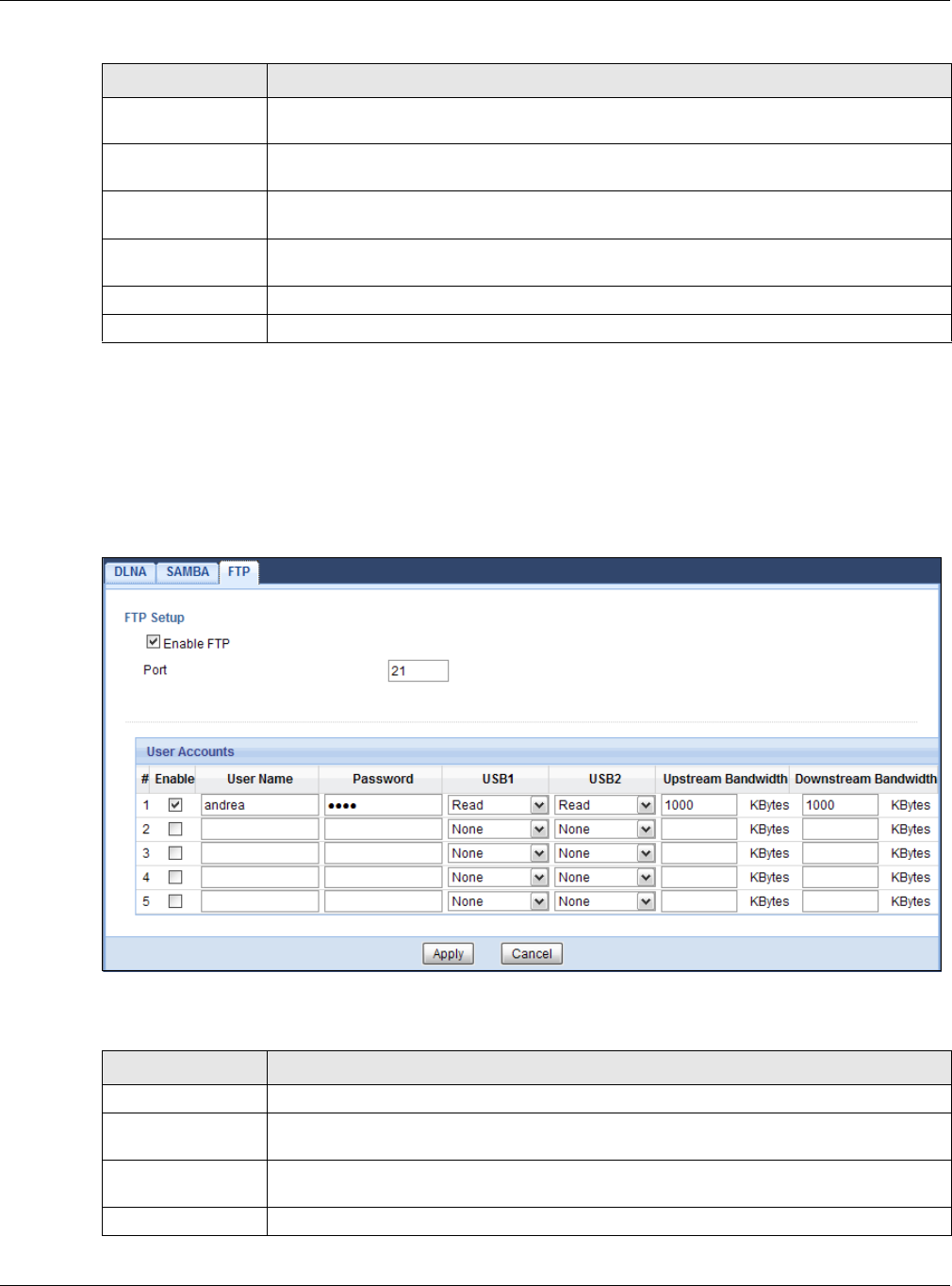
Chapter 23 USB Media Sharing
EMG3425-Q10A User’s Guide
169
23.7 FTP Screen
Use this screen to set up file sharing via the EMG3425-Q10A using FTP and create user accounts.
Click M a nagem ent > USB M edia Sh a ring > FTP.
Figure 103 Management > USB Media Sharing > FTP
The following table describes the labels in this screen.
Enable This field displays whether a user account is activated or not. Select the check box to
enable the account. Clear the check box to disable the account.
User Name Enter a user name that will be allowed to access the shared files. You can enter up to 20
characters. Only letters and numbers allowed.
Password Enter the password used to access the shared files. You can enter up to 20 characters.
Only letters and numbers are allowed. The password is case sensitive.
USB1/2 Select the USB port(s) of the EMG3425-Q10A. The configured user can access the files
on the USB device(s) connected to the selected USB port(s) only.
Apply Click Apply to save your changes back to the EMG3425-Q10A.
Cancel Click Cancel to begin configuring this screen afresh.
Table 70 Management > USB Media Sharing > SAMBA (continued)
LABEL DESCRIPTION
Table 71 Management > USB Media Sharing > FTP
LABEL DESCRIPTION
Enable FTP Select this to enable the FTP server on the EMG3425-Q10A for file sharing using FTP.
Port You may change the server port number for FTP if needed, however you must use the
same port number in order to use that service for file sharing.
User Accounts Before you can share files you need a user account. Configure the following fields to set
up a file-sharing account.
#This is the index number of the user account.

Chapter 23 USB Media Sharing
EMG3425-Q10A User’s Guide
170
23.8 Example of Accessing Your Shared Files From a
Computer
You can use Windows Explorer or FTP to access the USB storage devices connected to the
EMG3425-Q10A.
This example shows you how to use Microsoft’s Windows XP to browse your shared files. Refer to
your operating system’s documentation for how to browse your file structure.
23.8.1 Use Windows Explorer to Share Files
You should have enabled file sharing and create a user account (Bob/1234 for example) with read
and write access to USB 1 in the USB M edia Sha r ing > SAM BA screen.
Open Windows Explorer to access the connected USB device using either Windows Explorer browser
or by browsing to your workgroup.
Enable This field displays whether a user account is activated or not. Select the check box to
enable the account. Clear the check box to disable the account.
User Name Enter a user name that will be allowed to access the shared files. You can enter up to 20
characters. Only letters and numbers allowed.
Password Enter the password used to access the shared files. You can enter up to 20 characters.
Only letters and numbers are allowed. The password is case sensitive.
USB1/2 Specify the user’s access rights to the USB storage device which is connected to the
EMG3425-Q10A’s USB port.
Read & W rit e - The user has read and write rights, meaning that the user can create
and edit the files on the connected USB device.
Read - The user has read rights only and can not create or edit the files on the
connected USB device.
N on e - The user cannot access the files on the USB device(s) connected to the USB
port.
Upstream
Bandwidth
Enter the maximum bandwidth (in Kbps) allowed for incoming FTP traffic.
Downstream
Bandwidth
Enter the maximum bandwidth (in Kbps) allowed for outgoing FTP traffic.
Apply Click Apply to save your changes back to the EMG3425-Q10A.
Cancel Click Cancel to begin configuring this screen afresh.
Table 71 Management > USB Media Sharing > FTP (continued)
LABEL DESCRIPTION
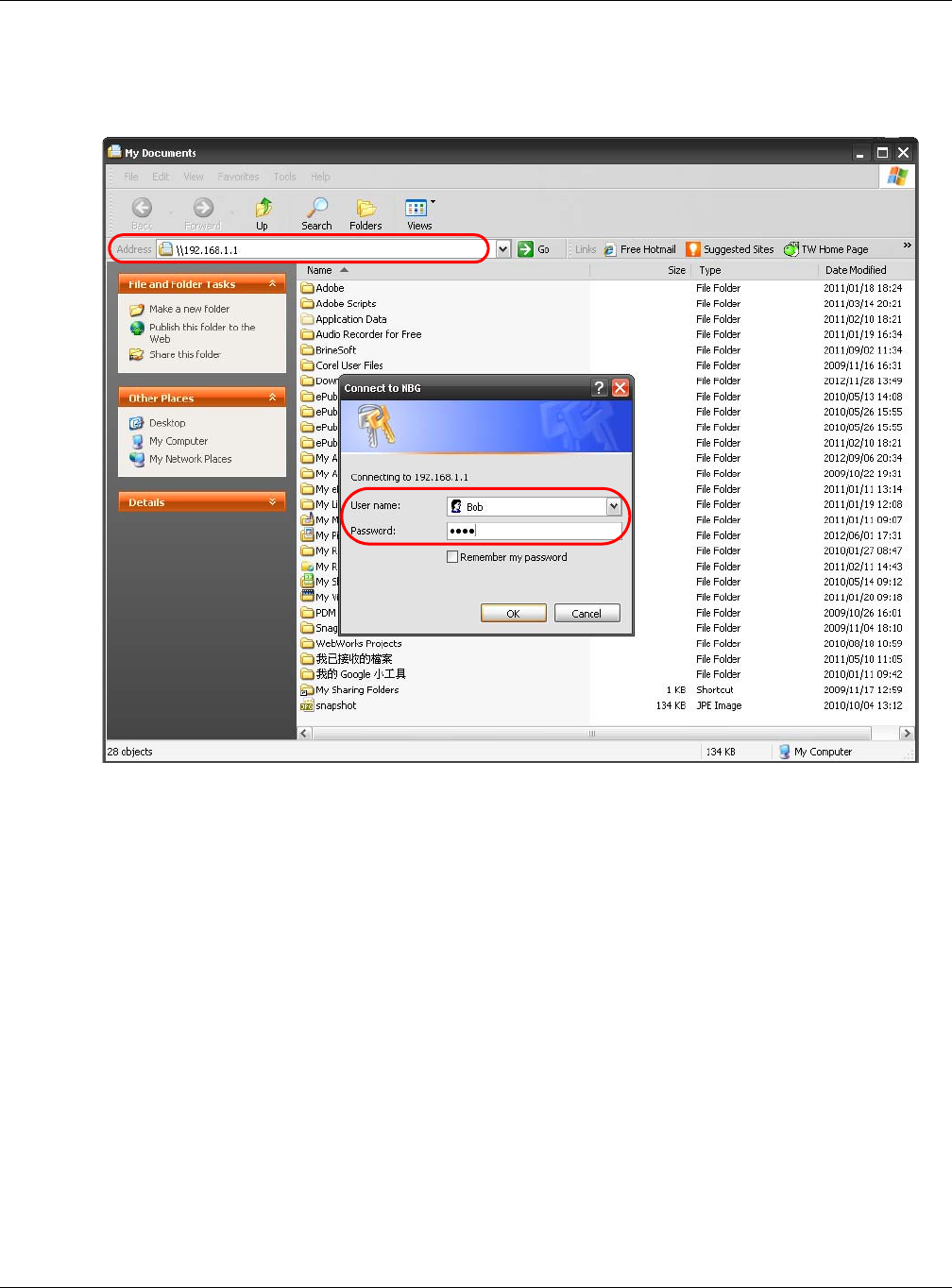
Chapter 23 USB Media Sharing
EMG3425-Q10A User’s Guide
171
1In Windows Explorer’s Address bar type a double backslash “\\” followed by the IP address of the
EMG3425-Q10A (the default IP address of the EMG3425-Q10A in router mode is 192.168.1.1) and
press [ENTER]. A screen asking for password authentication appears. Type the user name and
password (Bob and 1234 in this example) and click OK.
Note: Once you log into the shared folder via your EMG3425-Q10A, you do not have to
relogin unless you restart your computer.
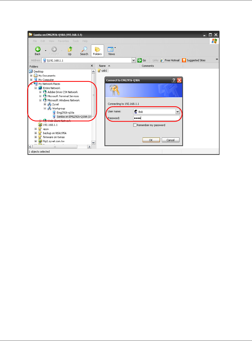
Chapter 23 USB Media Sharing
EMG3425-Q10A User’s Guide
172
2You can also use the workgroup name to access files by browsing to the workgroup folder using the
folder tree on the left side of the screen. It is located under My N et w or k Places. In this example
the workgroup name is the default “Workgroup”.
23.8.2 Use FTP to Share Files
You can use FTP to access the USB storage devices connected to the EMG3425-Q10A. In this
example, we use the web browser to share files via FTP from the LAN. The way or screen you log
into the FTP server (on the EMG3425-Q10A) varies depending on your FTP client. See your FTP
client documentation for more information.
You should have enabled file sharing and create a user account (Bob/1234 for example) with read
and write access to USB 1 in the USB M edia Sha r ing > FTP screen.
1In your web browser’s address or URL bar type “ftp://” followed by the IP address of the EMG3425-
Q10A (the default LAN IP address of the EMG3425-Q10A in router mode is 192.168.1.1) and click
Go or press [ENTER].
Chapter 23 USB Media Sharing
EMG3425-Q10A User’s Guide
173
2A screen asking for password authentication appears. Enter the user name and password (you
configured in the USB Media Sha r ing > FTP screen) and click Log On.
3The screen changes and shows you the folder for the USB storage device connected to your
EMG3425-Q10A. Double-click the folder to display the contents in it.
EMG3425-Q10A User’s Guide
174
CHAPTER 24
Port Configuration
24.1 Overview
The EMG3425-Q10A has 1000Base-T auto-negotiating Ethernet ports. In 10/100/1000 Mbps
Gigabit Ethernet, the speed can be 10 Mbps, 100 Mbps or 1000 Mbps. The duplex mode can be both
half or full duplex. An auto-negotiating port can detect and adjust to the optimum Ethernet speed
(10/100/1000 Mbps) and duplex mode (full duplex or half duplex) of the connected device.
24.2 Port Configuration Screen
Use this screen to configure the EMG3425-Q10A port speed and duplex settings. Click
Conf igur at ion > Mana gem e nt > Por t Configurat ion.
Figure 104 Management > Port Configuration
The following table describes the labels on this screen.
Table 72 Management > Port Configuration
LABEL DESCRIPTION
WAN/LAN1~4 This field displays the Ethernet port of the EMG3425-Q10A.
Speed Select the speed of the Ethernet connection on this port. The choices are Aut o, 1 0 0 0 ,
1 0 0 and 1 0 .
Selecting Aut o (auto-negotiation) allows one port to negotiate with a peer port
automatically to obtain the connection speed that both ends support. If the peer port
does not support auto-negotiation or turns off this feature, the EMG3425-Q10A
determines the connection speed by detecting the signal on the cable and using half
duplex mode.

Chapter 24 Port Configuration
EMG3425-Q10A User’s Guide
175
Duplex Select the duplex mode of the Ethernet connection on this port. The choices are Aut o,
Full and Half.
Selecting Aut o (auto-negotiation) allows one port to negotiate with a peer port
automatically to obtain the duplex mode that both ends support. If the peer port does
not support auto-negotiation or turns off this feature, the EMG3425-Q10A determines
the connection speed by detecting the signal on the cable and using half duplex mode.
Apply Click Apply to save your changes with the EMG3425-Q10A.
Cancel Click Cancel to begin configuring this screen afresh.
Table 72 Management > Port Configuration (continued)
LABEL DESCRIPTION

EMG3425-Q10A User’s Guide
176
CHAPTER 25
Maintenance
25.1 Overview
This chapter provides information on the Main t e na n ce screens.
25.2 What You Can Do
•Use the Ge n e r a l screen to set the timeout period of the management session (Section 25.3 on
page 176).
•Use the Account screen to change your EMG3425-Q10A’s system password (Section 25.4 on
page 177).
•Use the Tim e screen to change your EMG3425-Q10A’s time and date (Section 25.5 on page
178).
•Use the Firm w are Upgr a de screen to upload firmware to your EMG3425-Q10A (Section 25.6 on
page 180).
•Use the Backup/ Restore screen to view information related to factory defaults, backup
configuration, and restoring configuration (Section 25.8 on page 183).
•Use the Restart screen to reboot the EMG3425-Q10A without turning the power off (Section
25.8 on page 183).
•Use the Sys OP M ode screen to select how you want to use your EMG3425-Q10A (Section 25.10
on page 184).
•Use the La n guage screen to change the language for the Web Configurator (Section 25.11 on
page 185).
•Use the Dia gnost ic > Ping screen to ping an IP address (Section 25.12 on page 185).
25.3 General Screen
Use this screen to set the management session timeout period. Click M a int e na n ce > General.
The following screen displays.
Chapter 25 Maintenance
EMG3425-Q10A User’s Guide
177
Figure 105 Maintenance > General
The following table describes the labels in this screen.
25.4 Account Screen
It is strongly recommended that you change your EMG3425-Q10A's password.
If you forget your EMG3425-Q10A's password (or IP address), you will need to reset the device.
See Section 25.8 on page 183 for details.
Click M a in t e na n ce > Accou nt . The screen appears as shown.
Figure 106 Maintenance > Account
The following table describes the labels in this screen.
Table 73 Maintenance > General
LABEL DESCRIPTION
System Name System Name is a unique name to identify the EMG3425-Q10A in an Ethernet network.
Domain Name Enter the domain name you want to give to the EMG3425-Q10A.
Administrator
Inactivity Timer
Type how many minutes a management session can be left idle before the session times
out. The default is 5 minutes. After it times out you have to log in with your password again.
Very long idle timeouts may have security risks. A value of "0" means a management
session never times out, no matter how long it has been left idle (not recommended).
Apply Click Apply to save your changes back to the EMG3425-Q10A.
Cancel Click Cancel to exit this screen without saving.
Table 74 Maintenance > Account
LABEL DESCRIPTION
User Account Entries
#This is the index number of a user account.
User Name The EMG3425-Q10A’s user account name.
Chapter 25 Maintenance
EMG3425-Q10A User’s Guide
178
25.4.1 Account Setup Screen
This screen allows you to change a user account password.
In the M a int ena nce > Account screen, click an Edit icon under Modify. The screen appears as
shown.
Figure 107 Maintenance > Account: Edit
The following table describes the labels in this screen.
25.5 Time Setting Screen
Use this screen to configure the EMG3425-Q10A’s time based on your local time zone. To change
your EMG3425-Q10A’s time and date, click Ma in t enance > Tim e . The screen appears as shown.
Group The belonging of the user account.
Modify Click the Edit icon to open the Account Setup screen. Account Setup screen allows to
change the user account password.
Table 74 Maintenance > Account (continued)
LABEL DESCRIPTION
Table 75 Maintenance > Account: Edit
LABEL DESCRIPTION
Username The user account name.
Old Password Type the default password or the existing password you use to access the system in this
field.
New Password Type your new system password (up to 30 characters). Note that as you type a password,
the screen displays as asterisk (*) for each character you type.
Retype to
Confirm
Type the new password again in this field.
Group This shows the group belonging of the user account (read-only).
Apply Click Apply to save your changes back to the EMG3425-Q10A.
Cancel Click Can cel to exit this screen without saving.
Chapter 25 Maintenance
EMG3425-Q10A User’s Guide
179
Figure 108 Maintenance > Time
The following table describes the labels in this screen.
Table 76 Maintenance > Time
LABEL DESCRIPTION
Current Time and Date
Current Time This field displays the time of your EMG3425-Q10A.
Each time you reload this page, the EMG3425-Q10A synchronizes the time with the time
server.
Current Date This field displays the date of your EMG3425-Q10A.
Each time you reload this page, the EMG3425-Q10A synchronizes the date with the time
server.
Current Time and Date Setup
Manual Select this radio button to enter the time and date manually. If you configure a new time
and date, Time Zone and Daylight Saving at the same time, the new time and date you
entered has priority and the Time Zone and Daylight Saving settings do not affect it.
New Time
(hh:mm:ss)
This field displays the last updated time from the time server or the last time configured
manually.
When you select M a nu a l, enter the new time in this field and then click Apply.
New Date
(yyyy/mm/dd)
This field displays the last updated date from the time server or the last date configured
manually.
When you select M a nu a l, enter the new date in this field and then click Apply.
Get from Time
Server
Select this radio button to have the EMG3425-Q10A get the time and date from the time
server you specified below.
User Defined
Time Server
Address
Enter the IP address or URL (up to 20 extended ASCII characters in length) of your time
server. Check with your ISP/network administrator if you are unsure of this information.

Chapter 25 Maintenance
EMG3425-Q10A User’s Guide
180
25.6 Firmware Upgrade Screen
Find firmware at www.zyxel.com in a file that (usually) uses the system model name with a “*.bin”
extension, e.g., “EMG3425-Q10A.bin”. The upload process uses HTTP (Hypertext Transfer Protocol)
and may take up to two minutes. After a successful upload, the system will reboot.
Click M a int enance > Firm w a r e Upgr ade. Follow the instructions in this screen to upload
firmware to your EMG3425-Q10A.
Time Zone Setup
Time Zone Choose the time zone of your location. This will set the time difference between your time
zone and Greenwich Mean Time (GMT).
Daylight
Savings
Daylight saving is a period from late spring to early fall when many countries set their clocks
ahead of normal local time by one hour to give more daytime light in the evening.
Select this option if you use Daylight Saving Time.
Start Date Configure the day and time when Daylight Saving Time starts if you selected Da ylight
Savin gs. The o’clock field uses the 24 hour format. Here are a couple of examples.
Daylight Saving Time starts in most parts of the United States on the first Sunday of April.
Each time zone in the United States starts using Daylight Saving Time at 2 A.M local time.
So in the United States you would select First , Sunday, Apr il and type 2 in the o’clock
field.
Daylight Saving Time starts in the European Union on the last Sunday of March. All of the
time zones in the European Union start using Daylight Saving Time at the same moment (1
A.m. GMT or UTC). So in the European Union you would select La st , Sun day, Ma r ch . The
time you type in the o’clock field depends on your time zone. In Germany for instance, you
would type 2 because Germany’s time zone is one hour ahead of GMT or UTC (GMT+1).
End Date Configure the day and time when Daylight Saving Time ends if you selected Da ylight
Savin gs. The o’clock field uses the 24 hour format. Here are a couple of examples.
Daylight Saving Time ends in the United States on the last Sunday of October. Each time
zone in the United States stops using Daylight Saving Time at 2 A.M. local time. So in the
United States you would select Last, Sunda y, Oct obe r and type 2 in the o’clo ck field.
Daylight Saving Time ends in the European Union on the last Sunday of October. All of the
time zones in the European Union stop using Daylight Saving Time at the same moment (1
A.M. GMT or UTC). So in the European Union you would select La st, Sunda y, Oct ober. The
time you type in the o’clock field depends on your time zone. In Germany for instance, you
would type 2 because Germany’s time zone is one hour ahead of GMT or UTC (GMT + 1).
Apply Click Apply to save your changes back to the EMG3425-Q10A.
Cancel Click Can cel to exit this screen without saving.
Table 76 Maintenance > Time (continued)
LABEL DESCRIPTION
Chapter 25 Maintenance
EMG3425-Q10A User’s Guide
181
Figure 109 Maintenance > Firmware Upgrade
The following table describes the labels in this screen.
Do not turn off the EMG3425-Q10A while firmware upload is in progress!
After you see the Firm w ar e Uploa d I n Pr ocess screen, wait two minutes before logging into the
EMG3425-Q10A again.
The EMG3425-Q10A automatically restarts in this time causing a temporary network disconnect. In
some operating systems, you may see the following icon on your desktop.
Figure 110 Network Temporarily Disconnected
After two minutes, log in again and check your new firmware version in the St a t u s screen.
If the upload was not successful, an error message appears.
25.7 Configuration Backup/Restore Screen
Backup configuration allows you to back up (save) the EMG3425-Q10A’s current configuration to a
file on your computer. Once your EMG3425-Q10A is configured and functioning properly, it is highly
recommended that you back up your configuration file before making configuration changes. The
backup configuration file will be useful in case you need to return to your previous settings.
Restore configuration allows you to upload a new or previously saved configuration file from your
computer to your EMG3425-Q10A.
Table 77 Maintenance > Firmware Upgrade
LABEL DESCRIPTION
Firmware Upgrade
File Path Type in the location of the file you want to upload in this field or click Choose File to find it.
Choose File Click Choose File to find the .bin file you want to upload. Remember that you must
decompress compressed (.zip) files before you can upload them.
Upload Click Upload to begin the upload process. This process may take up to two minutes.
Chapter 25 Maintenance
EMG3425-Q10A User’s Guide
182
Click M a int enance > Ba ck up/ Rest ore. Information related to factory defaults, backup
configuration, and restoring configuration appears as shown next.
Figure 111 Maintenance > Backup/Restore
The following table describes the labels in this screen.
Note: If you uploaded the default configuration file you may need to change the IP
address of your computer to be in the same subnet as that of the default
EMG3425-Q10A IP address (192.168.1.1). See Appendix B on page 203 for details
on how to set up your computer’s IP address.
Table 78 Maintenance > Backup/Restore
LABEL DESCRIPTION
Backup Configuration
Backup Click Ba ckup to save the EMG3425-Q10A’s current configuration to your computer.
Restore Configuration
File Path Click Ch oose File to browse to the location of the configuration file in your computer.
Upload Click Upload to begin the upload process.
Note: Do not turn off the EMG3425-Q10A while configuration file upload is in progress.
After you see a “configuration upload successful” screen, you must then wait one minute
before logging into the EMG3425-Q10A again. The EMG3425-Q10A automatically restarts in
this time causing a temporary network disconnect.
If you see an error screen, click Back to return to the Backup/Restore screen.
Reset Pressing the Rese t button in this section clears all user-entered configuration information
and returns the EMG3425-Q10A to its factory defaults.
You can also press the RESET button on the rear panel to reset the factory defaults of your
EMG3425-Q10A. Refer to the chapter about introducing the Web Configurator for more
information on the RESET button.
Chapter 25 Maintenance
EMG3425-Q10A User’s Guide
183
25.8 Restart Screen
System restart allows you to reboot the EMG3425-Q10A without turning the power off.
Click M a int enance > Resta r t to open the following screen.
Figure 112 Maintenance > Restart
Click Re st ar t to have the EMG3425-Q10A reboot. This does not affect the EMG3425-Q10A's
configuration.
25.9 System Operation Mode Overview
The Sys OP M ode (System Operation Mode) function lets you configure your EMG3425-Q10A as an
router or access point. You can choose between Router or Acce ss Point M ode depending on your
network topology and the features you require from your device.
The following describes the device modes available in your EMG3425-Q10A.
Router
A router connects your local network with another network, such as the Internet. The router has
two IP addresses, the LAN IP address and the WAN IP address.
Figure 113 LAN and WAN IP Addresses in Router Mode
Access Point
An access point enabled all ethernet ports to be bridged together and be in the same subnet. To
connect to the Internet, another device, such as a router, is required.
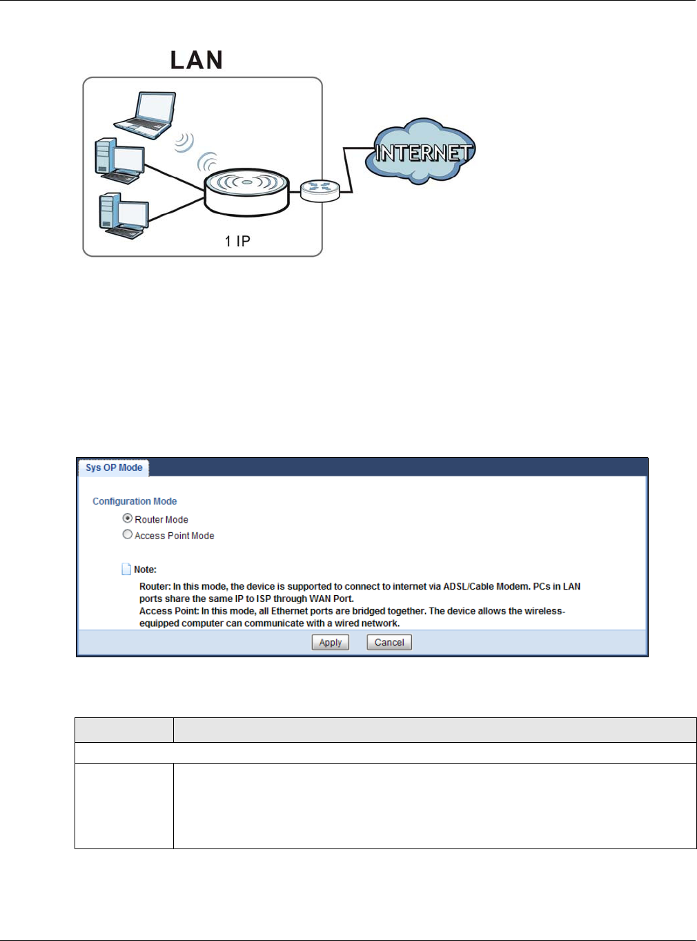
Chapter 25 Maintenance
EMG3425-Q10A User’s Guide
184
Figure 114 Access Point Mode
25.10 Sys OP Mode Screen
Use this screen to select how you want to use your EMG3425-Q10A.
Note: If you select the incorrect System Operation Mode you may not be able to connect
to the Internet.
Figure 115 Maintenance > Sys OP Mode
The following table describes the labels in the Sys OP M ode screen.
Table 79 Maintenance > Sys OP Mode
LABEL DESCRIPTION
Configuration Mode
Router Mode Select Rout e r Mode if your device routes traffic between a local network and another
network such as the Internet. This mode offers services such as a firewall or bandwidth
management.
You can configure the IP address settings on your WAN port. Contact your ISP or system
administrator for more information on appropriate settings.
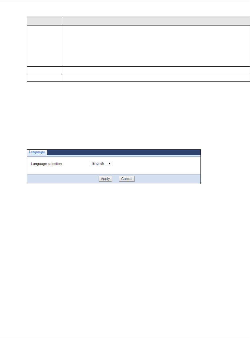
Chapter 25 Maintenance
EMG3425-Q10A User’s Guide
185
25.11 Language Screen
Use this screen to change the language for the Web Configurator.
Select the language you prefer and click Apply. The Web Configurator language changes after a
while without restarting the EMG3425-Q10A.
Figure 116 Maintenance > Language
25.12 Diagnostic Ping Screen
Use this screen to ping an IP address.
Access Point Select Access Point M ode if your device bridges traffic between clients on the same
network.
•In Acce ss Poin t M ode , all Ethernet ports have the same IP address.
• All ports on the rear panel of the device are LAN ports, including the port labeled WAN.
There is no WAN port.
• The DHCP server on your device is disabled.
• The IP address of the device on the local network is set to 192.168.1.2.
Apply Click Apply to save your settings.
Cancel Click Cancel to exit this screen without saving.
Table 79 Maintenance > Sys OP Mode (continued)
LABEL DESCRIPTION
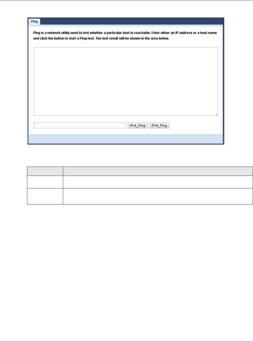
Chapter 25 Maintenance
EMG3425-Q10A User’s Guide
186
Figure 117 Maintenance > Diagnostic > Ping
The following table describes the labels in the Sys OP M ode screen.
Table 80 Maintenance > Sys OP Mode
LABEL DESCRIPTION
Type the IP address of a computer that you want to perform ping in order to test a
connection.
IPv4_Ping
IPv6_Ping
Click this to ping the IP address that you entered.

EMG3425-Q10A User’s Guide
187
CHAPTER 26
Troubleshooting
26.1 Overview
This chapter offers some suggestions to solve problems you might encounter. The potential
problems are divided into the following categories.
•Power, Hardware Connections, and LEDs
•EMG3425-Q10A Access and Login
•Internet Access
•Resetting the EMG3425-Q10A to Its Factory Defaults
•Wireless Connections
•USB Device Problems
26.2 Power, Hardware Connections, and LEDs
The EMG3425-Q10A does not turn on. None of the LEDs turn on.
1Make sure you are using the power adaptor or cord included with the EMG3425-Q10A.
2Make sure the power adaptor or cord is connected to the EMG3425-Q10A and plugged in to an
appropriate power source. Make sure the power source is turned on.
3Disconnect and re-connect the power adaptor or cord to the EMG3425-Q10A.
4If the problem continues, contact the vendor.
One of the LEDs does not behave as expected.
1Make sure you understand the normal behavior of the LED. See Section 1.7 on page 15.
2Check the hardware connections. See the Quick Start Guide.
3Inspect your cables for damage. Contact the vendor to replace any damaged cables.
4Disconnect and re-connect the power adaptor to the EMG3425-Q10A.

Chapter 26 Troubleshooting
EMG3425-Q10A User’s Guide
188
5If the problem continues, contact the vendor.
26.3 EMG3425-Q10A Access and Login
I don’t know the IP address of my EMG3425-Q10A.
1The default IP address of the EMG3425-Q10A in Router M ode is 1 9 2 .1 6 8 .1 .1 . The default IP
address of the EMG3425-Q10A in Access Point M ode is 1 9 2 .1 6 8 .1 .2 .
2If you changed the IP address and have forgotten it, you might get the IP address of the EMG3425-
Q10A in Router Mode by looking up the IP address of the default gateway for your computer. To do
this in most Windows computers, click Sta r t > Run, enter cm d, and then enter ipcon fig. The IP
address of the De fa u lt Ga t ew ay might be the IP address of the EMG3425-Q10A (it depends on the
network), so enter this IP address in your Internet browser.
3If your EMG3425-Q10A in Acce ss Point M ode is a DHCP client, you can find your IP address from
the DHCP server. This information is only available from the DHCP server which allocates IP
addresses on your network. Find this information directly from the DHCP server or contact your
system administrator for more information.
4Reset your EMG3425-Q10A to change all settings back to their default. This means your current
settings are lost. See Section 26.5 on page 191 in the Trou ble sh oot in g for information on
resetting your EMG3425-Q10A.
I forgot the password.
1The default password is 1 2 3 4 .
2If this does not work, you have to reset the device to its factory defaults. See Section 26.5 on page
191.
I cannot see or access the Login screen in the Web Configurator.
1Make sure you are using the correct IP address.
• The default IP address of the EMG3425-Q10A in Route r M ode is 1 9 2 .1 6 8 .1 .1 . The default IP
address of the EMG3425-Q10A in Access Point M ode is 1 9 2 .1 6 8 .1 .2 .
• If you changed the IP address (Section 10.4 on page 90), use the new IP address.
• If you changed the IP address and have forgotten it, see the troubleshooting suggestions for I
don’t know the IP address of my EMG3425-Q10A.

Chapter 26 Troubleshooting
EMG3425-Q10A User’s Guide
189
2Check the hardware connections, and make sure the LEDs are behaving as expected. See the Quick
Start Guide.
3Make sure your Internet browser does not block pop-up windows and has JavaScript and Java
enabled. See Appendix A on page 194.
4Make sure your computer is in the same subnet as the EMG3425-Q10A. (If you know that there are
routers between your computer and the EMG3425-Q10A, skip this step.)
• If there is a DHCP server on your network, make sure your computer is using a dynamic IP
address. See Section 10.4 on page 90.
• If there is no DHCP server on your network, make sure your computer’s IP address is in the
same subnet as the EMG3425-Q10A. See Section 10.4 on page 90.
5Reset the device to its factory defaults, and try to access the EMG3425-Q10A with the default IP
address. See Section 1.5 on page 14.
6If the problem continues, contact the network administrator or vendor, or try one of the advanced
suggestions.
Advance d Suggest ions
• Try to access the EMG3425-Q10A using another service, such as Telnet. If you can access the
EMG3425-Q10A, check the remote management settings and firewall rules to find out why the
EMG3425-Q10A does not respond to HTTP.
• If your computer is connected to the W AN port or is connected wirelessly, use a computer that is
connected to a LAN /ETH ERN ET port.
I can see the Login screen, but I cannot log in to the EMG3425-Q10A.
1Make sure you have entered the password correctly. The default password is 1 2 3 4 . This field is
case-sensitive, so make sure [Caps Lock] is not on.
2This can happen when you fail to log out properly from your last session. Try logging in again after
5 minutes.
3Disconnect and re-connect the power adaptor or cord to the EMG3425-Q10A.
4If this does not work, you have to reset the device to its factory defaults. See Section 26.5 on page
191.
26.4 Internet Access
I cannot access the Internet.

Chapter 26 Troubleshooting
EMG3425-Q10A User’s Guide
190
1Check the hardware connections, and make sure the LEDs are behaving as expected. See the Quick
Start Guide.
2Go to Maint ena n ce > Sys OP Mode. Check your System Operation Mode setting.
• If the EMG3425-Q10A is in Rout e r M ode , make sure the WAN port is connected to a
broadband modem or router with Internet access. Your computer and the EMG3425-Q10A
should be in the same subnet.
• If the EMG3425-Q10A is in Access Point Mode, make sure the WAN port is connected to a
broadband modem or router with Internet access and your computer is set to obtain an
dynamic IP address.
3If the EMG3425-Q10A is in Rout er Mode, make sure you entered your ISP account information
correctly in the wizard or the WAN screen. These fields are case-sensitive, so make sure [Caps
Lock] is not on.
4If you are trying to access the Internet wirelessly, make sure the wireless settings in the wireless
client are the same as the settings in the AP.
5Disconnect all the cables from your device, and follow the directions in the Quick Start Guide again.
6If the problem continues, contact your ISP.
I cannot access the Internet anymore. I had access to the Internet (with the EMG3425-
Q10A), but my Internet connection is not available anymore.
1Check the hardware connections, and make sure the LEDs are behaving as expected. See the Quick
Start Guide and Section 1.7 on page 15.
2Reboot the EMG3425-Q10A.
3If the problem continues, contact your ISP.
The Internet connection is slow or intermittent.
1There might be a lot of traffic on the network. Look at the LEDs, and check Section 1.7 on page 15.
If the EMG3425-Q10A is sending or receiving a lot of information, try closing some programs that
use the Internet, especially peer-to-peer applications.
2Check the signal strength. If the signal strength is low, try moving the EMG3425-Q10A closer to the
AP if possible, and look around to see if there are any devices that might be interfering with the
wireless network (for example, microwaves, other wireless networks, and so on).
3Reboot the EMG3425-Q10A.
4If the problem continues, contact the network administrator or vendor, or try one of the advanced
suggestions.
Advance d Suggest ion

Chapter 26 Troubleshooting
EMG3425-Q10A User’s Guide
191
• Check the settings for QoS. If it is disabled, you might consider activating it.
26.5 Resetting the EMG3425-Q10A to Its Factory Defaults
If you reset the EMG3425-Q10A, you lose all of the changes you have made. The EMG3425-Q10A
re-loads its default settings, and the password resets to 1 2 3 4 . You have to make all of your
changes again.
You will lose all of your changes when you push the RESET button.
To reset the EMG3425-Q10A:
1Make sure the power LED is on.
2Press the RESET button for one to four seconds to restart/reboot the EMG3425-Q10A.
3Press the RESET button for longer than five seconds to set the EMG3425-Q10A back to its factory-
default configurations.
If the EMG3425-Q10A restarts automatically, wait for the EMG3425-Q10A to finish restarting, and
log in to the Web Configurator. The password is “1234”.
If the EMG3425-Q10A does not restart automatically, disconnect and reconnect the EMG3425-
Q10A’s power. Then, follow the directions above again.
26.6 Wireless Connections
I cannot access the EMG3425-Q10A or ping any computer from the WLAN.
1Make sure the wireless LAN is enabled on the EMG3425-Q10A.
2Make sure the wireless adapter on your computer is working properly.
3Make sure the wireless adapter installed on your computer is IEEE 802.11 compatible and supports
the same wireless standard as the EMG3425-Q10A.
4Make sure your computer (with a wireless adapter installed) is within the transmission range of the
EMG3425-Q10A.
5Check that both the EMG3425-Q10A and the wireless adapter on your computer are using the same
wireless and wireless security settings.

Chapter 26 Troubleshooting
EMG3425-Q10A User’s Guide
192
6Make sure traffic between the WLAN and the LAN is not blocked by the firewall on the EMG3425-
Q10A.
7Make sure you allow the EMG3425-Q10A to be remotely accessed through the WLAN interface.
Check your remote management settings.
• See the chapter on Wireless LAN in the User’s Guide for more information.
I set up URL keyword blocking, but I can still access a website that should be blocked.
Make sure that you enable parental control in the Pare n t al Cont rol screen, set up rules and turn
on the rules. Make sure that the keywords that you type are listed in the rule’s Keyw ord List .
If a keyword that is listed in the Ke yw ord List is not blocked when it is found in a URL, customize
the keyword blocking using commands. See the Customizing Keyword Blocking URL Checking
section in the IPv6 Firewall chapter.
I cannot access the Web Configurator after I switched to AP mode.
When you change from router mode to AP mode, your computer must have an IP address in the
range between “192.168.1.3” and “192.168.1.254”.
Refer to Appendix B on page 203 for instructions on how to change your computer’s IP address.
What factors may cause intermittent or unstabled wireless connection? How can I solve this
problem?
The following factors may cause interference:
• Obstacles: walls, ceilings, furniture, and so on.
• Building Materials: metal doors, aluminum studs.
• Electrical devices: microwaves, monitors, electric motors, cordless phones, and other wireless
devices.
To optimize the speed and quality of your wireless connection, you can:
• Move your wireless device closer to the AP if the signal strength is low.
• Reduce wireless interference that may be caused by other wireless networks or surrounding
wireless electronics such as cordless phones.
• Place the AP where there are minimum obstacles (such as walls and ceilings) between the AP and
the wireless client.
• Reduce the number of wireless clients connecting to the same AP simultaneously, or add
additional APs if necessary.

Chapter 26 Troubleshooting
EMG3425-Q10A User’s Guide
193
• Try closing some programs that use the Internet, especially peer-to-peer applications. If the
wireless client is sending or receiving a lot of information, it may have too many programs open
that use the Internet.
• Position the antennas for best reception. If the AP is placed on a table or floor, point the antennas
upwards. If the AP is placed at a high position, point the antennas downwards. Try pointing the
antennas in different directions and check which provides the strongest signal to the wireless
clients.
26.7 USB Device Problems
I cannot access or see a USB device that is connected to the EMG3425-Q10A.
1Disconnect the problematic USB device, then reconnect it to the EMG3425-Q10A.
2Ensure that the USB device has power.
3Check your cable connections.
4Restart the EMG3425-Q10A by disconnecting the power and then reconnecting it.
5If the USB device requires a special driver, install the driver from the installation disc that came
with the device. After driver installation, reconnect the USB device to the EMG3425-Q10A and try to
connect to it again with your computer.
6If the problem persists, contact your vendor.
What kind of USB devices do the EMG3425-Q10A support?
1It is strongly recommended to use version 2.0 or lower USB storage devices (such as memory
sticks, USB hard drives) and/or USB devices. Other USB products are not guaranteed to function
properly with the EMG3425-Q10A.

EMG3425-Q10A User’s Guide
194
APPENDIX A
Pop-up Windows, JavaScript and Java
Permissions
In order to use the web configurator you need to allow:
• Web browser pop-up windows from your device.
• JavaScript (enabled by default).
• Java permissions (enabled by default).
Note: The screens used below belong to Internet Explorer version 6, 7 and 8. Screens for
other Internet Explorer versions may vary.
Internet Explorer Pop-up Blockers
You may have to disable pop-up blocking to log into your device.
Either disable pop-up blocking (enabled by default in Windows XP SP (Service Pack) 2) or allow
pop-up blocking and create an exception for your device’s IP address.
Disable Pop-up Blockers
1In Internet Explorer, select Tools, Pop- up Block er and then select Turn Off Pop- up Block e r.
Figure 118 Pop-up Blocker
You can also check if pop-up blocking is disabled in the Pop- u p Blocker section in the Privacy tab.
1In Internet Explorer, select Tools, I nt ernet Options, Pr ivacy.
2Clear the Block pop- ups check box in the Pop- u p Block er section of the screen. This disables any
web pop-up blockers you may have enabled.
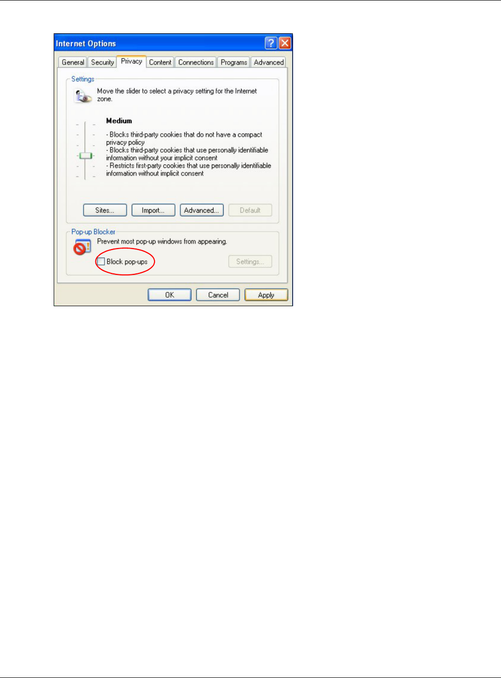
Appendix A Pop-up Windows, JavaScript and Java Permissions
EMG3425-Q10A User’s Guide
195
Figure 119 Internet Options: Privacy
3Click Apply to save this setting.
Enable Pop-up Blockers with Exceptions
Alternatively, if you only want to allow pop-up windows from your device, see the following steps.
1In Internet Explorer, select Tools, I nt ernet Options and then the Priv a cy tab.
2Select Se t t in gs…to open the Pop- up Block er Se t t ings screen.
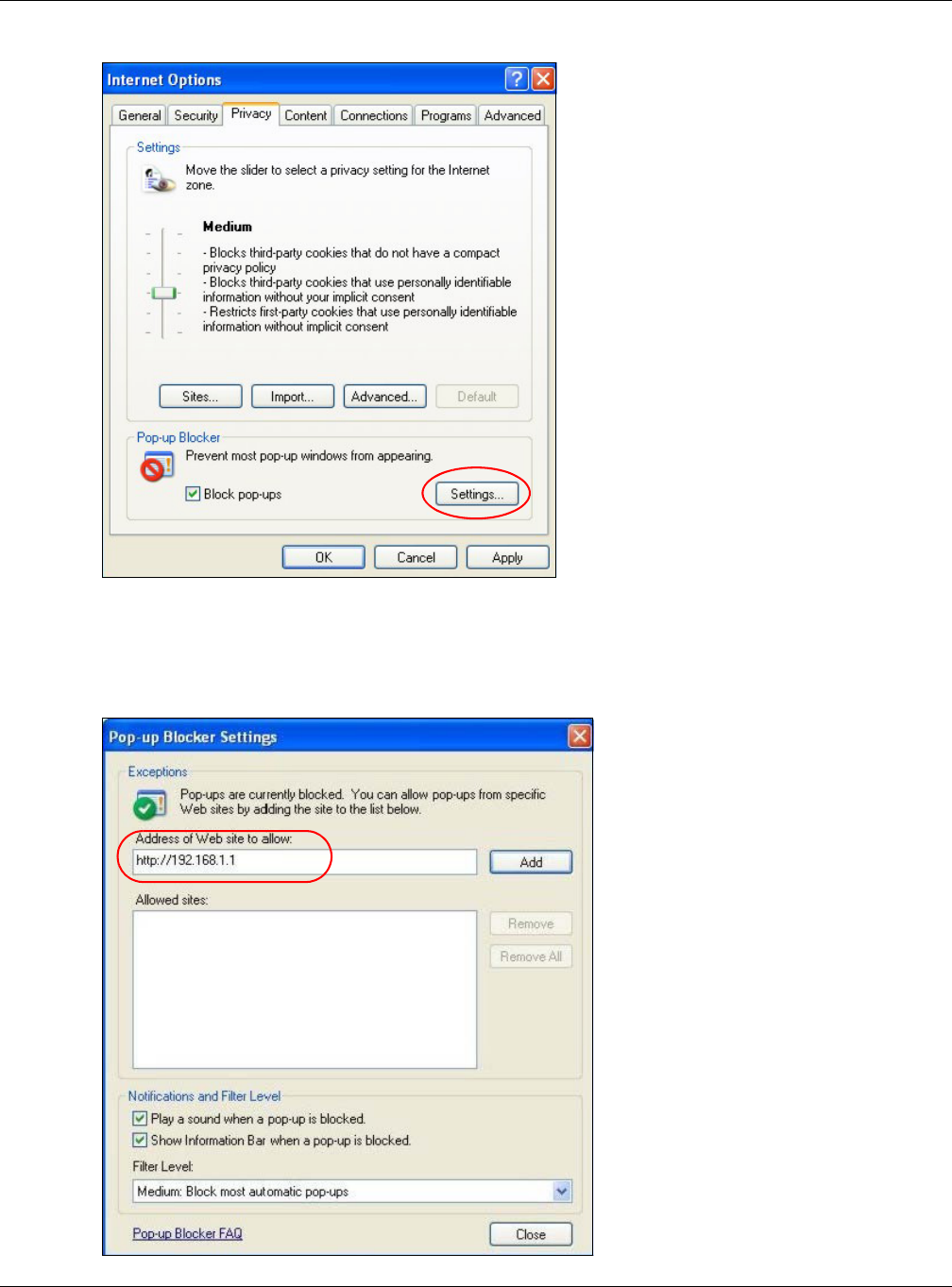
Appendix A Pop-up Windows, JavaScript and Java Permissions
EMG3425-Q10A User’s Guide
196
Figure 120 Internet Options: Privacy
3Type the IP address of your device (the web page that you do not want to have blocked) with the
prefix “http://”. For example, http://192.168.167.1.
4Click Add to move the IP address to the list of Allow ed sit e s.
Figure 121 Pop-up Blocker Settings
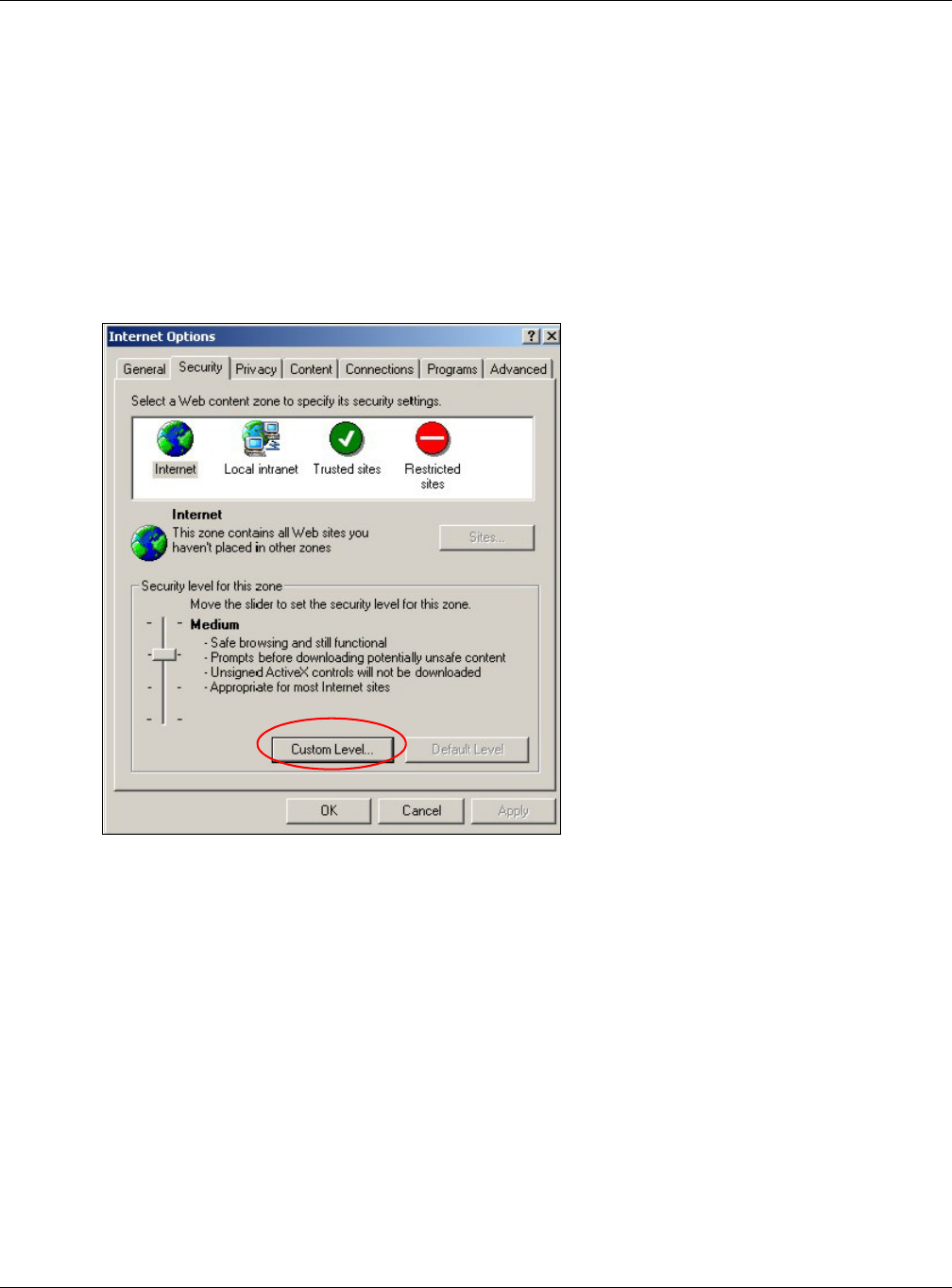
Appendix A Pop-up Windows, JavaScript and Java Permissions
EMG3425-Q10A User’s Guide
197
5Click Close to return to the Priva cy screen.
6Click Apply to save this setting.
JavaScript
If pages of the web configurator do not display properly in Internet Explorer, check that JavaScript
are allowed.
1In Internet Explorer, click Tools, I nt er n e t Options and then the Se curit y tab.
Figure 122 Internet Options: Security
2Click the Custom Level... button.
3Scroll down to Scr ip t in g.
4Under Act ive script ing make sure that Enable is selected (the default).
5Under Script in g of Ja va applet s make sure that Enable is selected (the default).
6Click OK to close the window.
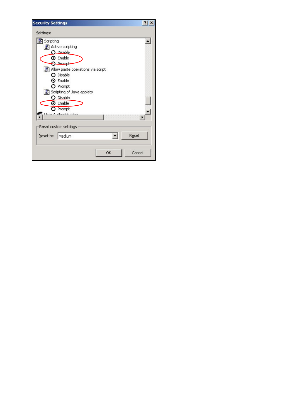
Appendix A Pop-up Windows, JavaScript and Java Permissions
EMG3425-Q10A User’s Guide
198
Figure 123 Security Settings - Java Scripting
Java Permissions
1From Internet Explorer, click Tools, I nt e r ne t Opt ions and then the Secu r ity tab.
2Click the Custom Level... button.
3Scroll down to Microsoft V M .
4Under Java perm issions make sure that a safety level is selected.
5Click OK to close the window.
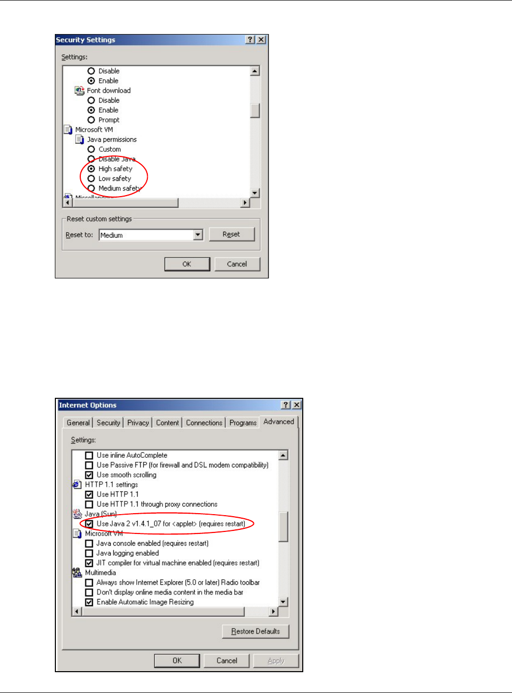
Appendix A Pop-up Windows, JavaScript and Java Permissions
EMG3425-Q10A User’s Guide
199
Figure 124 Security Settings - Java
JAVA (Sun)
1From Internet Explorer, click Tools, I nt e r ne t Opt ions and then the Adva nce d tab.
2Make sure that Use Java 2 for < applet > under Java ( Sun) is selected.
3Click OK to close the window.
Figure 125 Java (Sun)
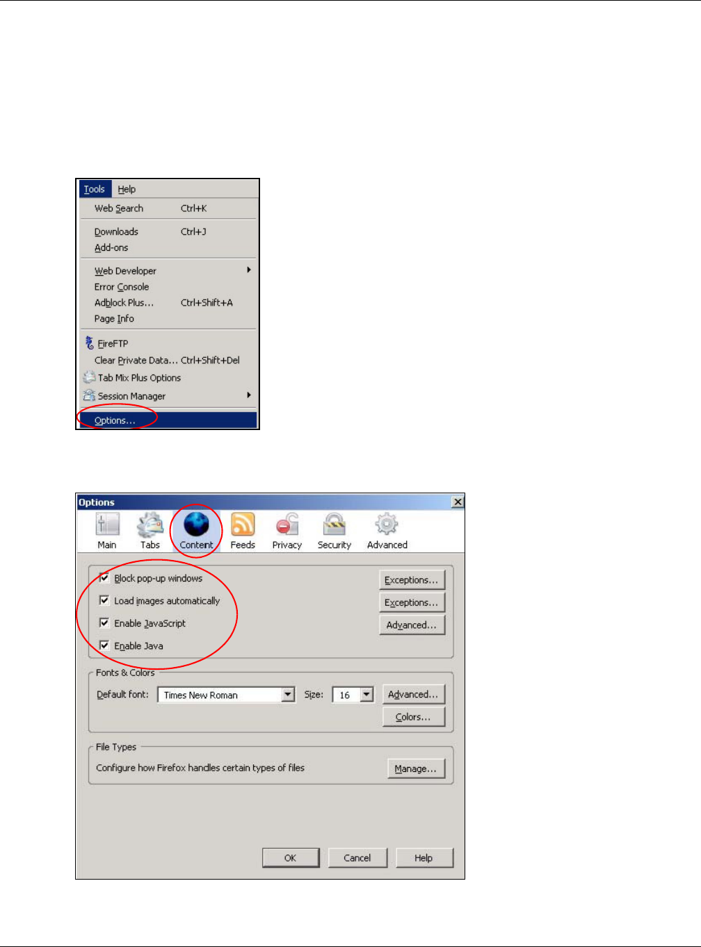
Appendix A Pop-up Windows, JavaScript and Java Permissions
EMG3425-Q10A User’s Guide
200
Mozilla Firefox
Mozilla Firefox 2.0 screens are used here. Screens for other versions may vary slightly. The steps
below apply to Mozilla Firefox 3.0 as well.
You can enable Java, Javascript and pop-ups in one screen. Click Tools, then click Opt ions in the
screen that appears.
Figure 126 Mozilla Firefox: TOOLS > Options
Click Content to show the screen below. Select the check boxes as shown in the following screen.
Figure 127 Mozilla Firefox Content Security