ZyXEL Communications EMG6765-Q10A AC2200 Gigabit Ethernet MoCA Gateway AC2200 Gigabit Ethernet Gateway User Manual Book
ZyXEL Communications Corporation AC2200 Gigabit Ethernet MoCA Gateway AC2200 Gigabit Ethernet Gateway Book
UserManual.wiki
>
ZyXEL Communications
>
EMG6765 Q10A User Manual
User Manual
Navigation menu
Upload a User Manual
Namespaces
Wiki Guide
HTML
PDF
Info
Views
User Manual
Discussion / Help
Navigation

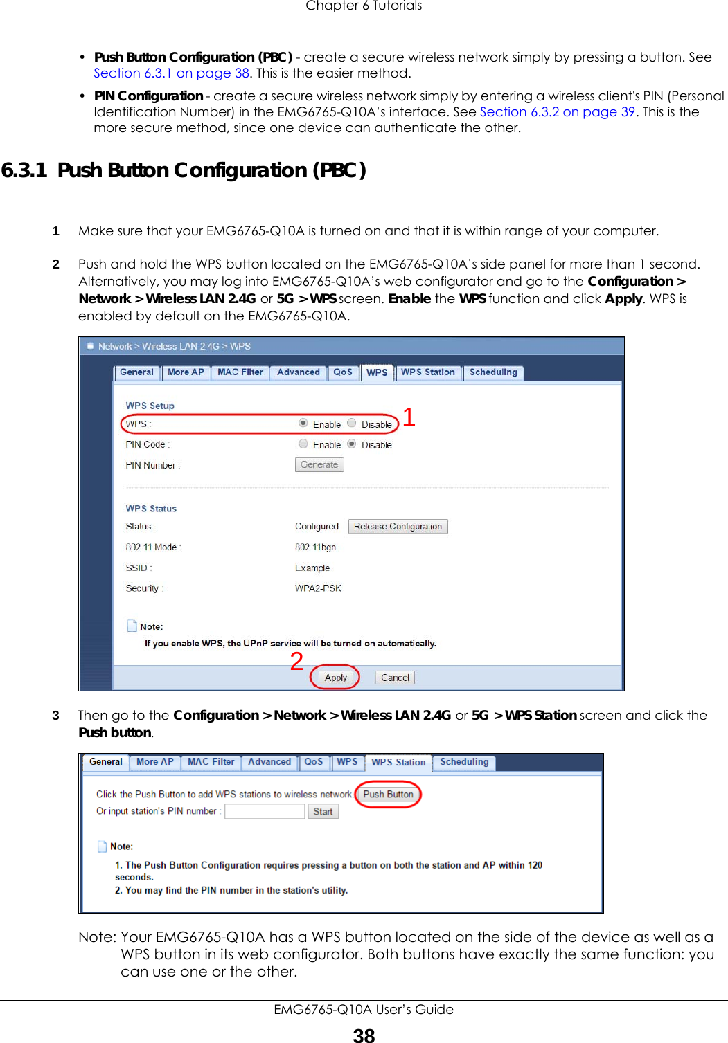
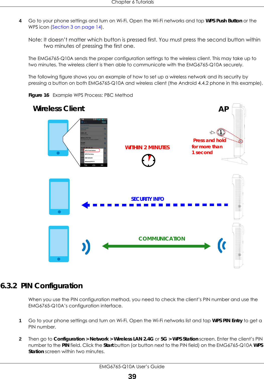
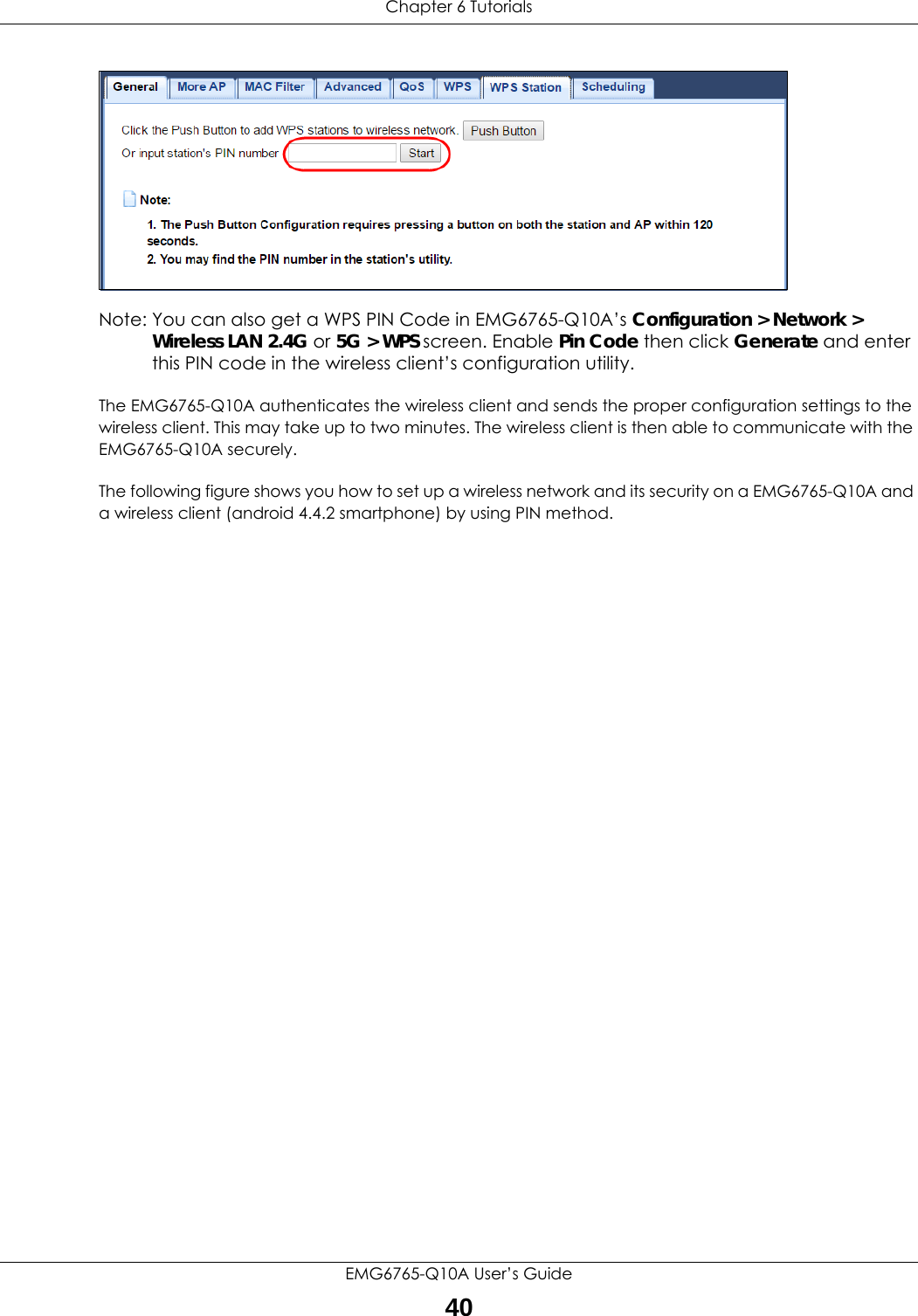
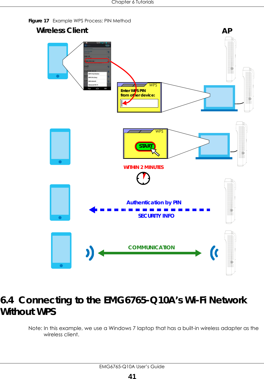
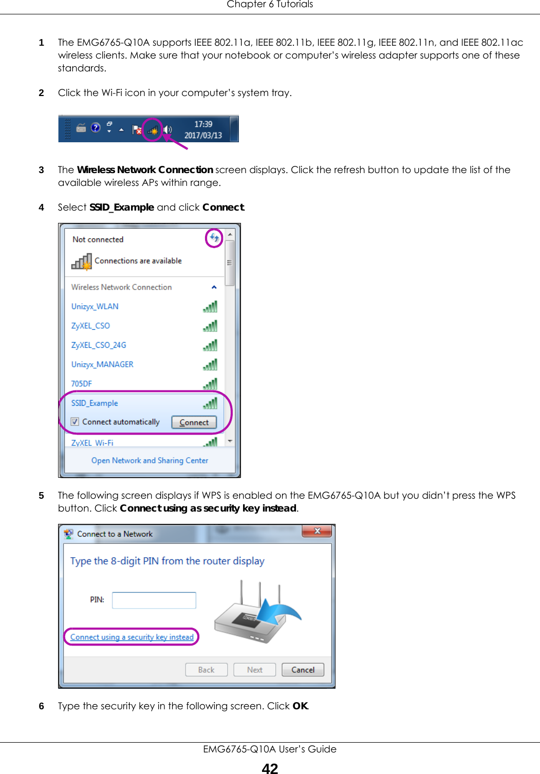
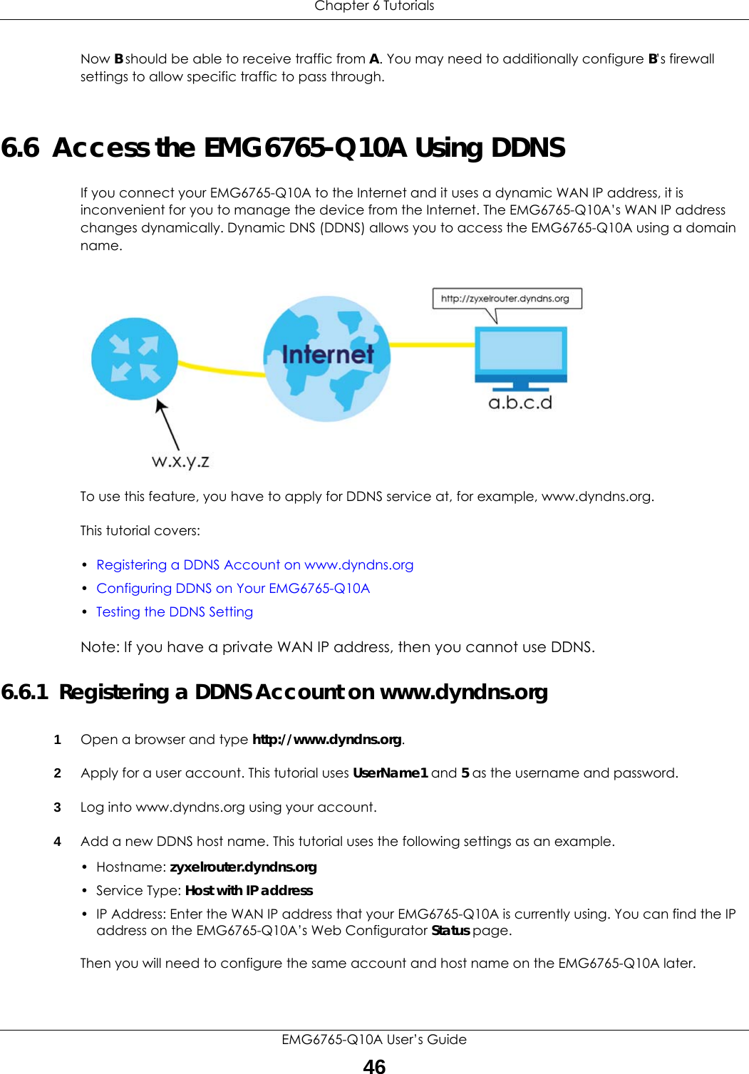
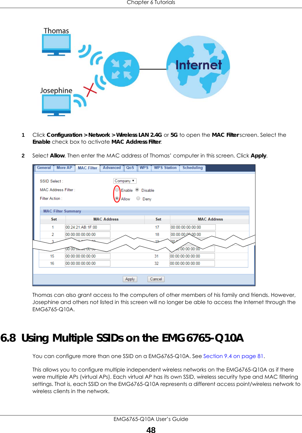
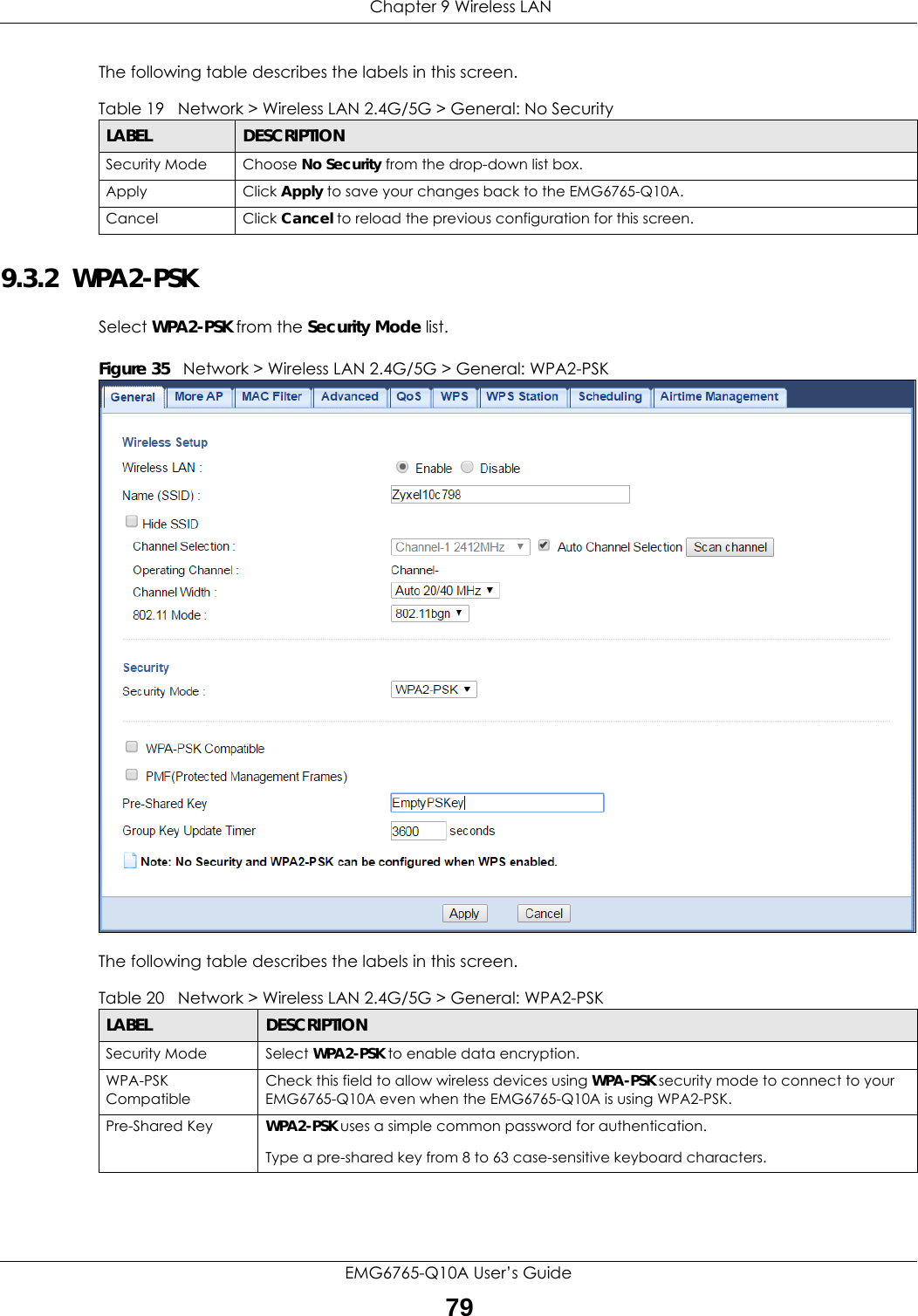
![Chapter 6 TutorialsEMG6765-Q10A User’s Guide476.6.2 Configuring DDNS on Your EMG6765-Q10AConfigure the following settings in the Network Setting > DNS > Dynamic DNS screen.•Select Enable Dynamic DNS.•Select www.DynDNS.com as the service provider.•Type zyxelrouter.dyndns.org in the Host Name field.• Enter the user name (UserName1) and password (5).Click Apply.6.6.3 Testing the DDNS SettingNow you should be able to access the EMG6765-Q10A from the Internet. To test this:1Open a web browser on the computer (using the IP address a.b.c.d) that is connected to the Internet.2Type http://zyxelrouter.dyndns.org and press [Enter].3The EMG6765-Q10A’s login page should appear. You can then log into the EMG6765-Q10A and manage it.6.7 Configuring the MAC Address FilterThomas noticed that his daughter Josephine spends too much time surfing the web and downloading media files. He decided to prevent Josephine from accessing the Internet so that she can concentrate on preparing for her final exams.Josephine’s computer connects wirelessly to the Internet through the EMG6765-Q10A. Thomas decides to use the Configuration > Network > Wireless LAN 2.4G or 5G > MAC Filter screen to grant wireless network access to his computer but not to Josephine’s computer.](https://usermanual.wiki/ZyXEL-Communications/EMG6765-Q10A/User-Guide-3484519-Page-47.png)
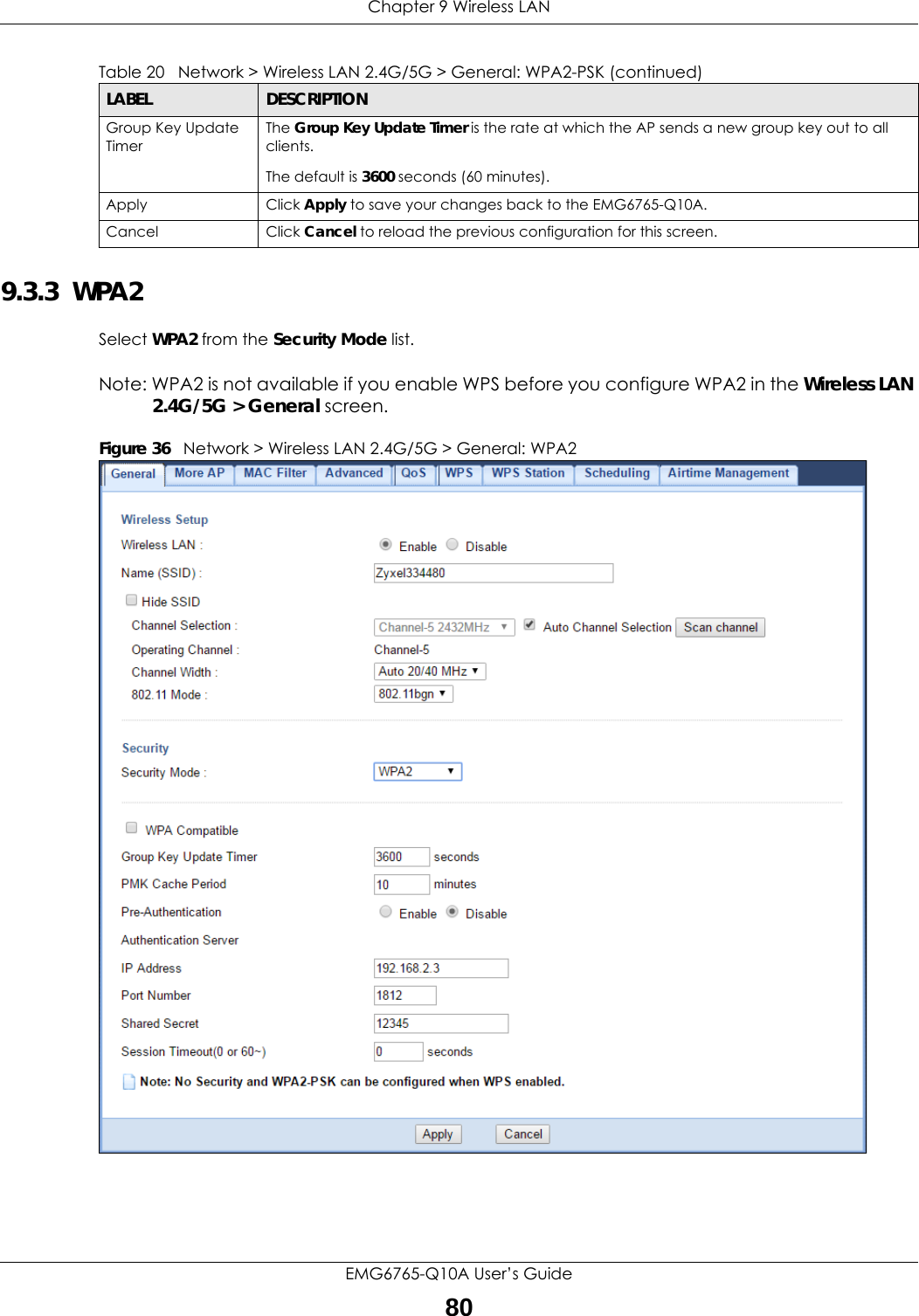


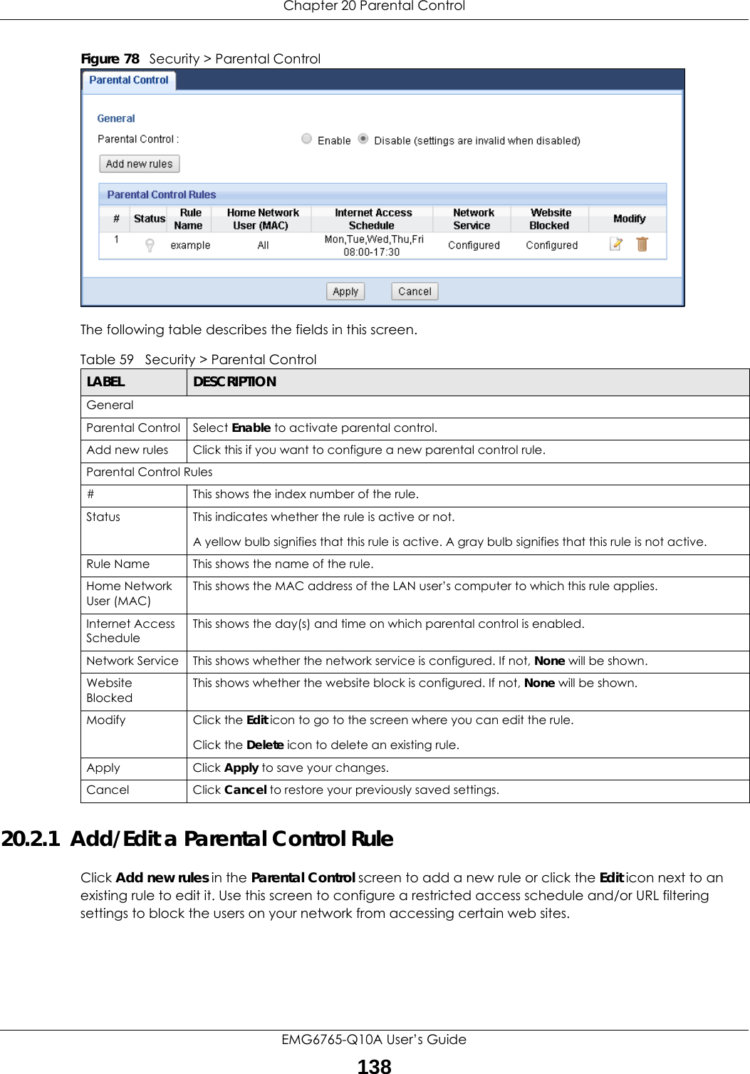
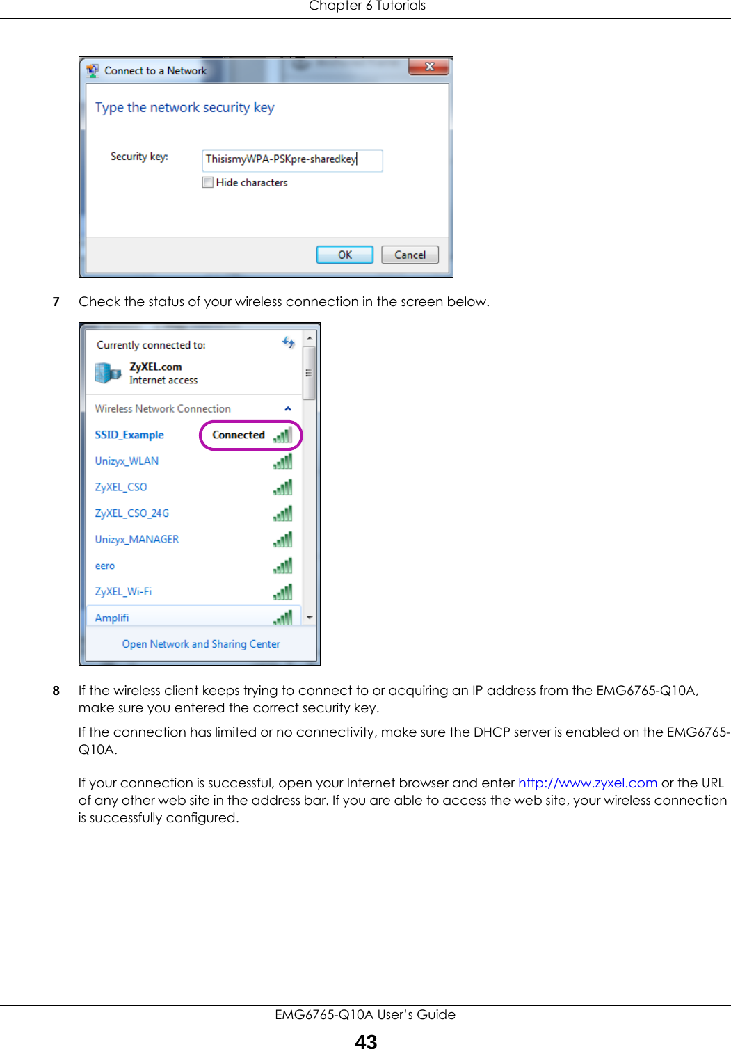
![Chapter 20 Parental ControlEMG6765-Q10A User’s Guide14120.3 Technical ReferenceThe following section contains additional technical information about the EMG6765-Q10A features described in this chapter.20.3.1 Customizing Keyword Blocking URL CheckingYou can use commands to set how much of a website’s URL the content filter is to check for keyword blocking. See the appendices for information on how to access and use the command interpreter.Domain Name or IP Address URL CheckingBy default, the EMG6765-Q10A checks the URL’s domain name or IP address when performing keyword blocking.This means that the EMG6765-Q10A checks the characters that come before the first slash in the URL.For example, with the URL www.zyxel.com.tw/news/pressroom.php, content filtering only searches for keywords within www.zyxel.com.tw.Full Path URL CheckingFull path URL checking has the EMG6765-Q10A check the characters that come before the last slash in the URL.For example, with the URL www.zyxel.com.tw/news/pressroom.php, full path URL checking searches for keywords within www.zyxel.com.tw/news/.Use the ip urlfilter customize actionFlags 6 [disable | enable] command to extend (or not extend) the keyword blocking search to include the URL's full path.File Name URL CheckingFilename URL checking has the EMG6765-Q10A check all of the characters in the URL.For example, filename URL checking searches for keywords within the URL www.zyxel.com.tw/news/pressroom.php.Use the ip urlfilter customize actionFlags 8 [disable | enable] command to extend (or not extend) the keyword blocking search to include the URL's complete filename.Apply Click Apply to save your settings with the EMG6765-Q10A.Back Click Back to return to the previous screen.Table 61 Security > Parental Control > Add/Edit new rules > Add/Edit new service (continued)LABEL DESCRIPTION](https://usermanual.wiki/ZyXEL-Communications/EMG6765-Q10A/User-Guide-3484519-Page-141.png)
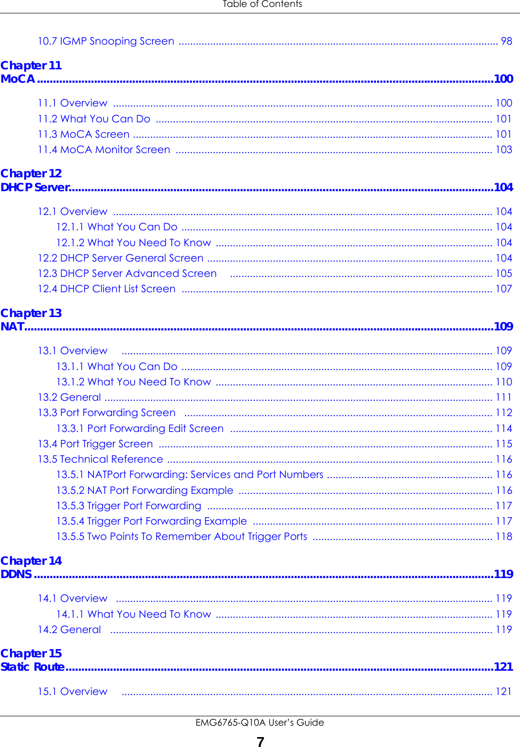
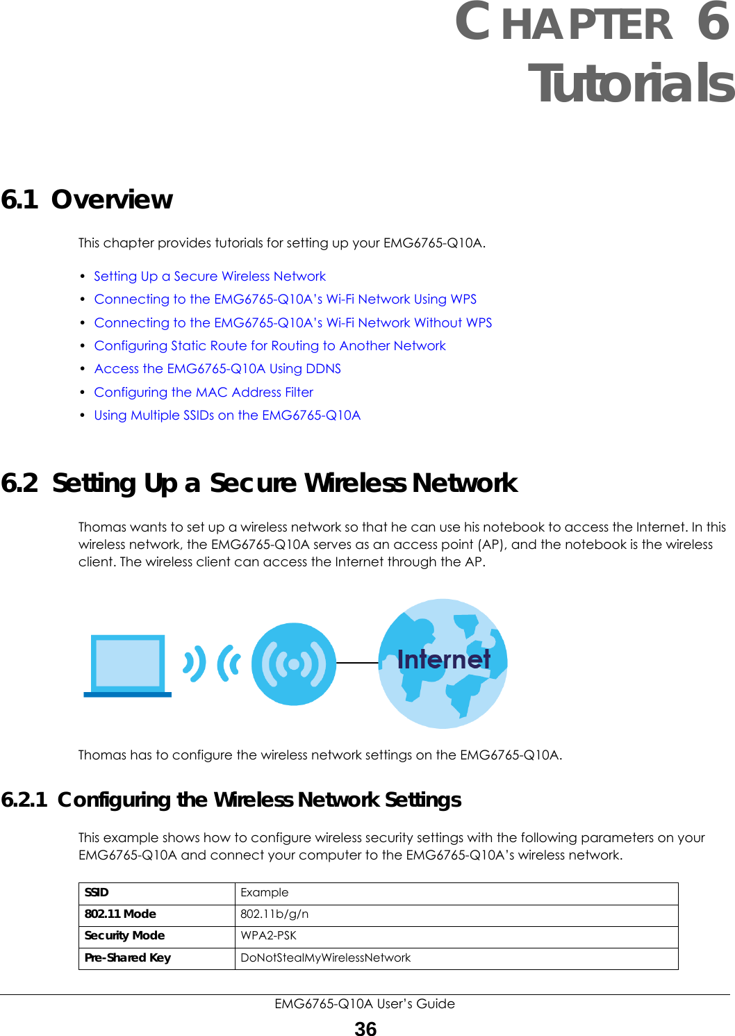
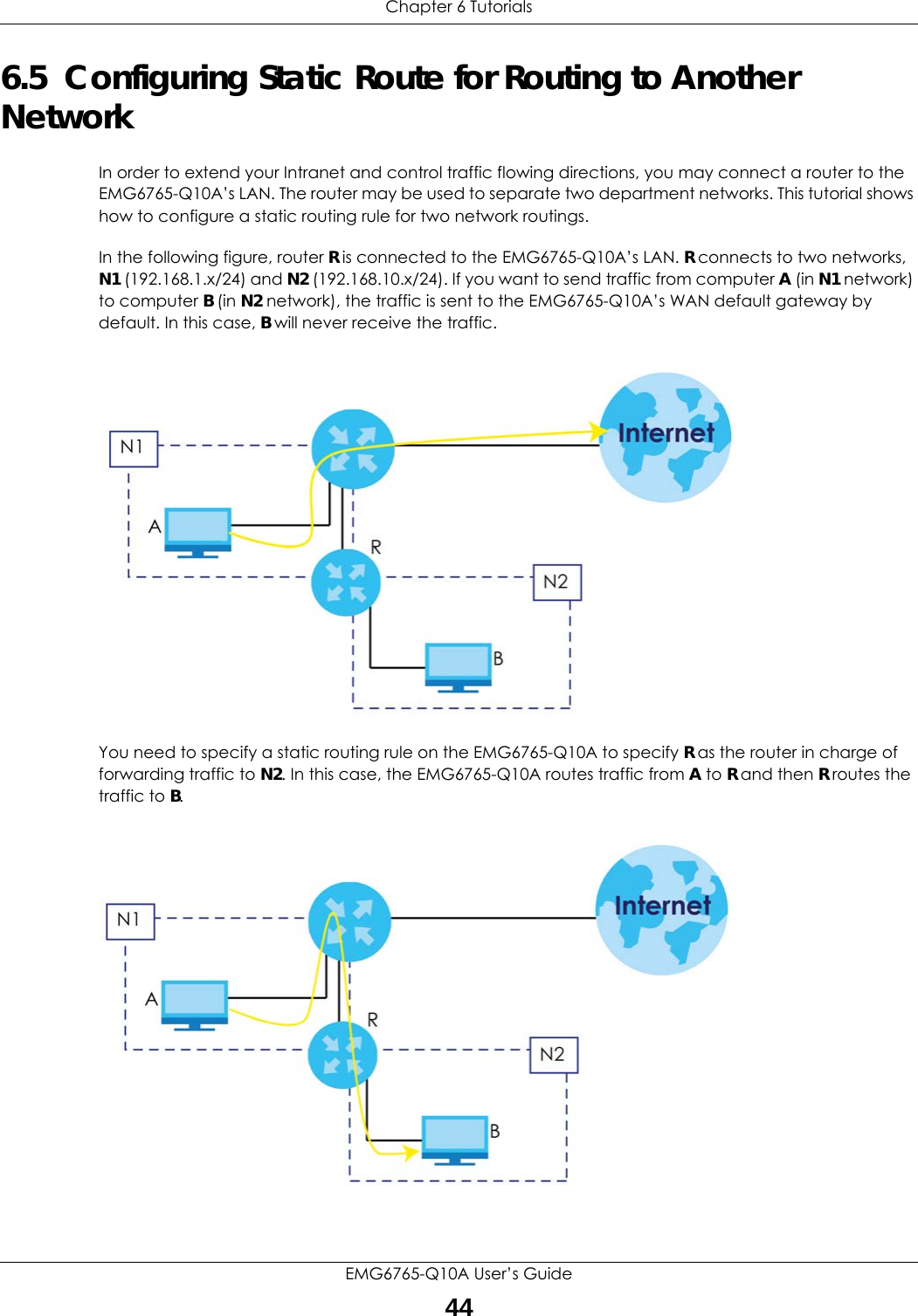
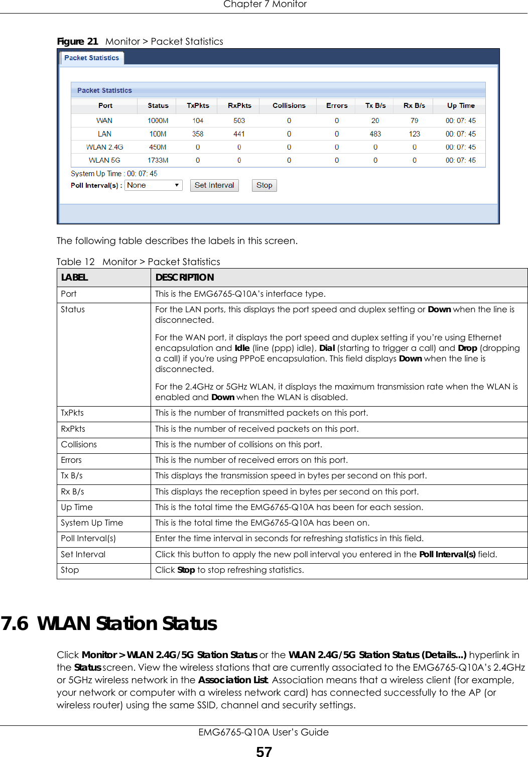
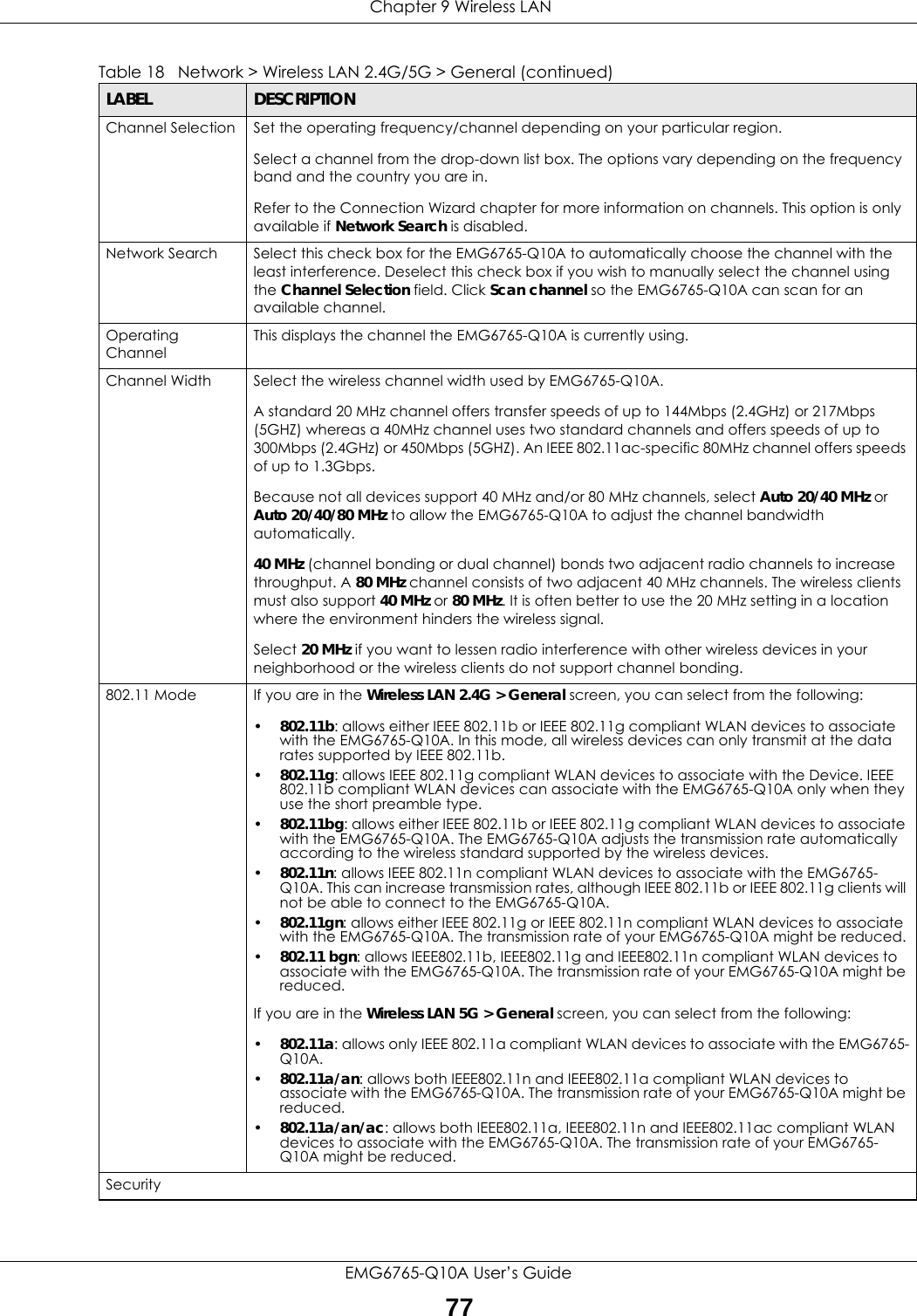
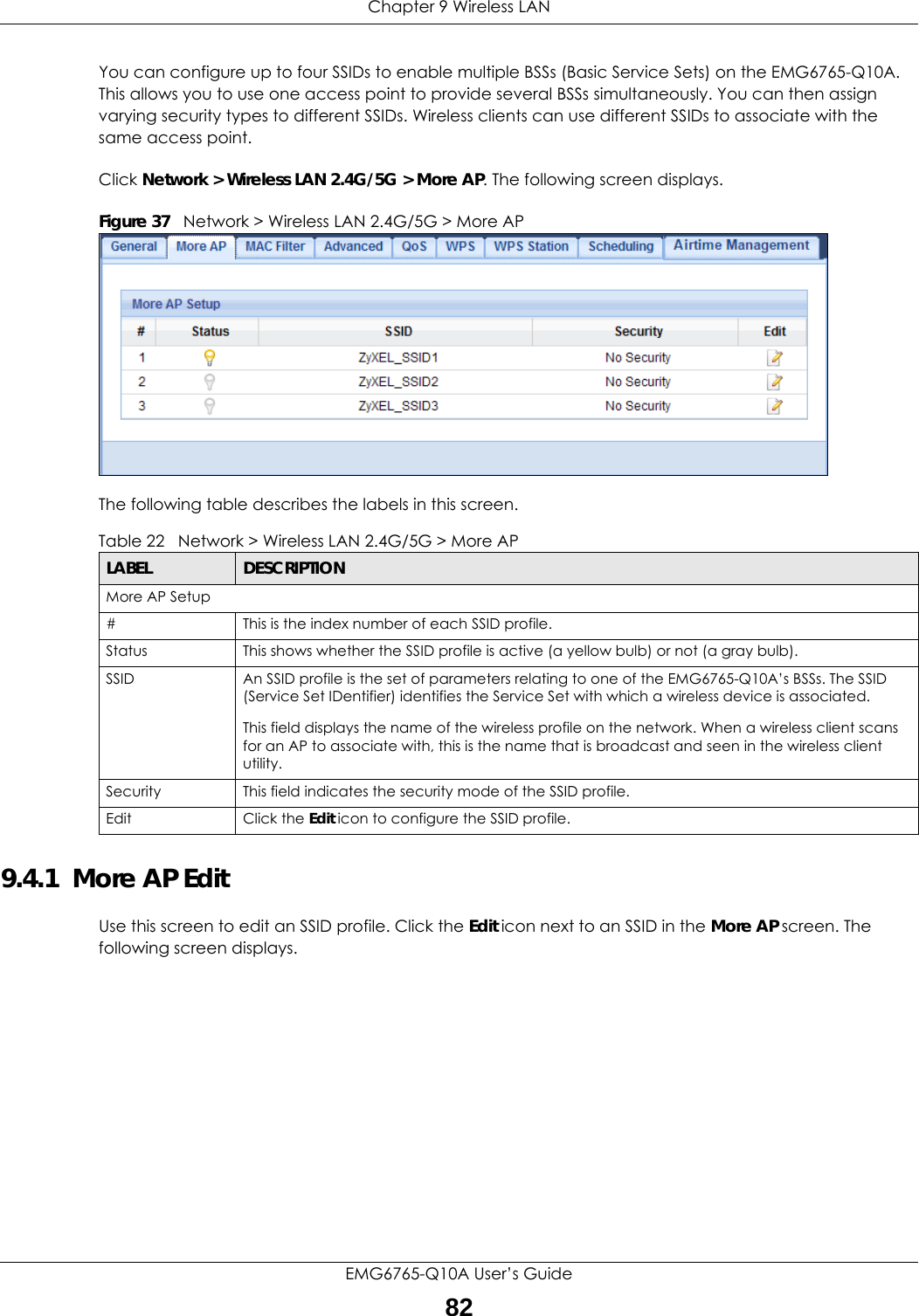
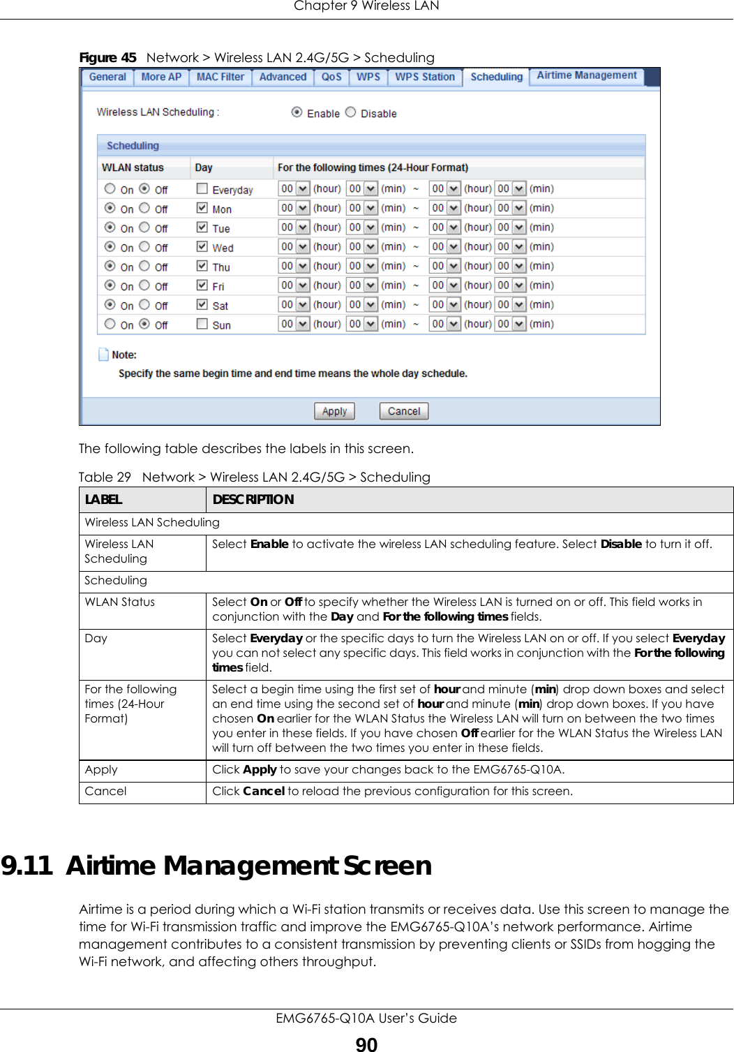
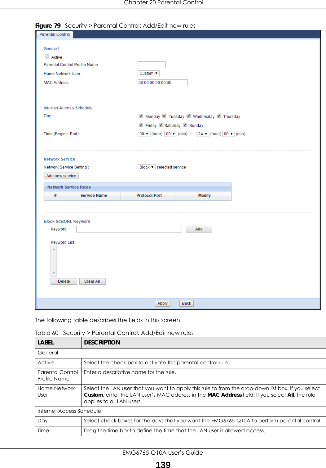
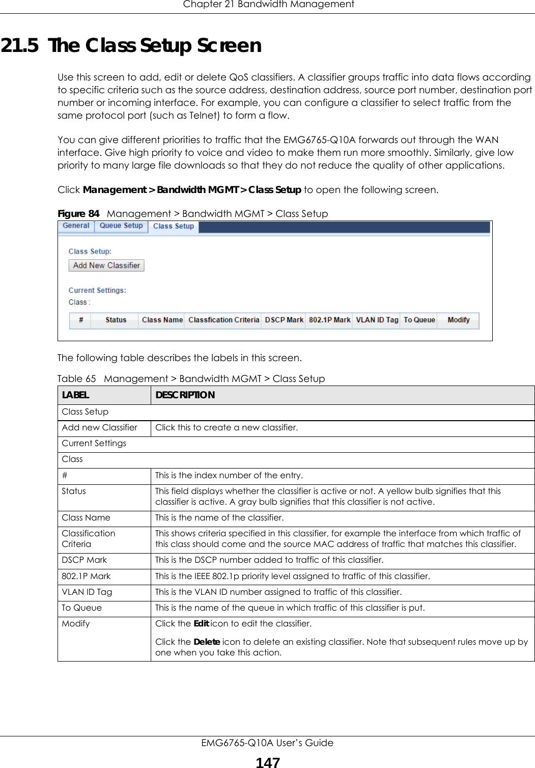
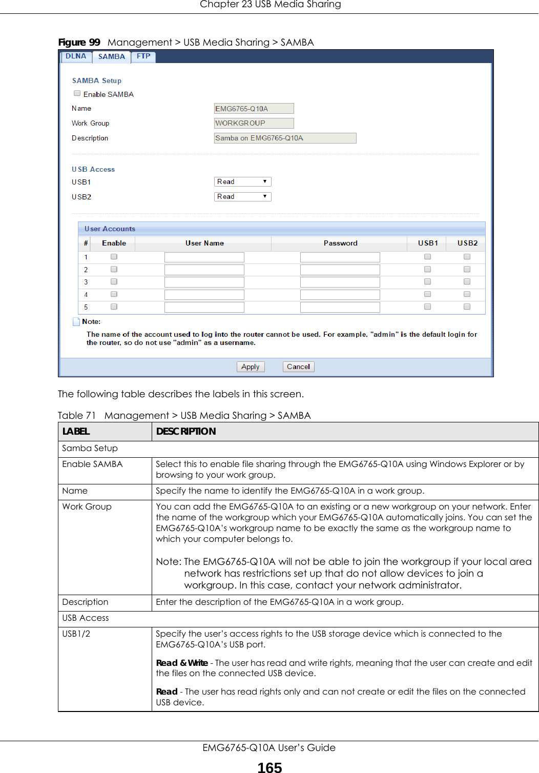
![Chapter 21 Bandwidth ManagementEMG6765-Q10A User’s Guide14621.4.1 Add/Edit a Queue Click Add New Queue or the Edit icon in the Queue Setup screen to configure a queue. Figure 83 Management > Bandwidth MGMT > Queue Setup: Add/Edit new queue The following table describes the labels in this screen. Rate Limit This shows the maximum transmission rate allowed for traffic on this queue.Modify Click the Edit icon to edit the queue.Click the Delete icon to delete an existing queue. Note that subsequent rules move up by one when you take this action.Table 63 Management > Bandwidth MGMT > Queue Setup (continued)LABEL DESCRIPTIONTable 64 Management > Bandwidth MGMT > Queue Setup: Add/Edit new queueLABEL DESCRIPTIONActive Select to enable or disable this queue.Name Enter the descriptive name of this queue. Note that \"<>%\\^[]`\+\$\,='#&@.:() are not allowed.To Interface Select the interface to which this queue is applied.Priority Select the priority level (from 1 to 7) of this queue.The smaller the number, the higher the priority level. Traffic assigned to higher priority queues gets through faster while traffic in lower priority queues is dropped if the network is congested.Weight Select the weight (from 1 to 8) of this queue. If two queues have the same priority level, the EMG6765-Q10A divides the bandwidth across the queues according to their weights. Queues with larger weights get more bandwidth than queues with smaller weights.Rate Limit Specify the maximum transmission rate (in Kbps) allowed for traffic on this queue.Back Click this to return to the previous screen.Apply Click this to save your changes.Cancel Click this to exit this screen without saving.](https://usermanual.wiki/ZyXEL-Communications/EMG6765-Q10A/User-Guide-3484519-Page-146.png)
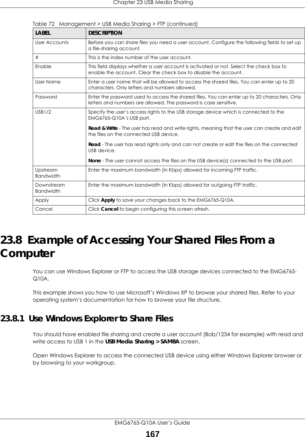
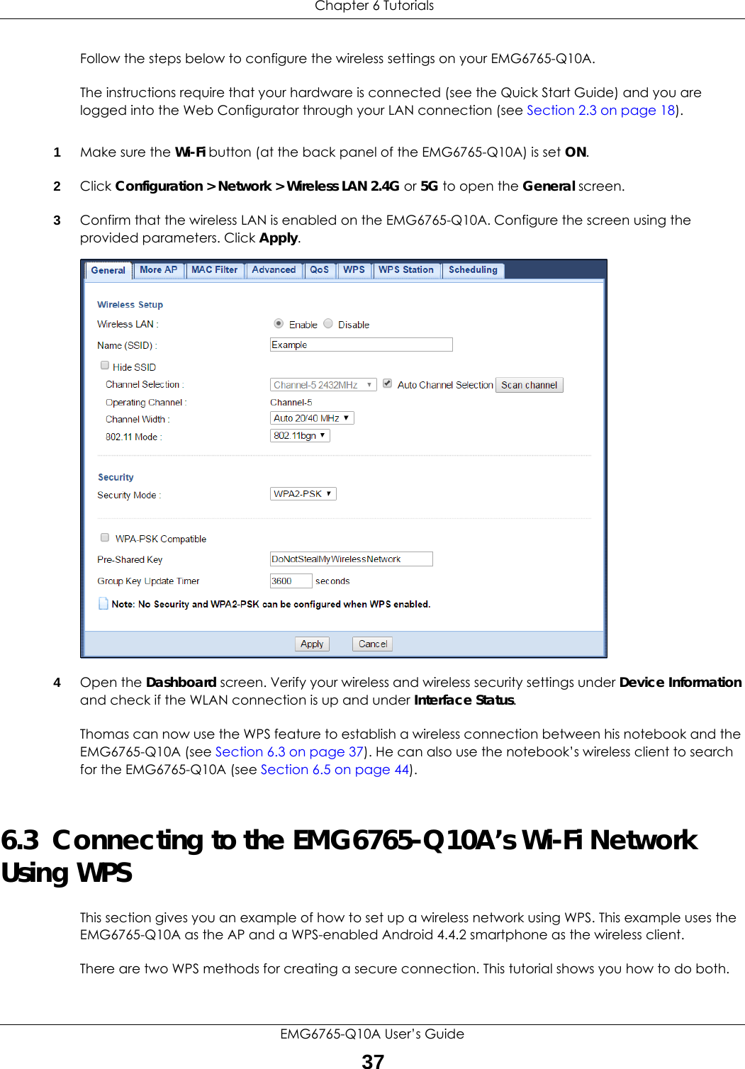
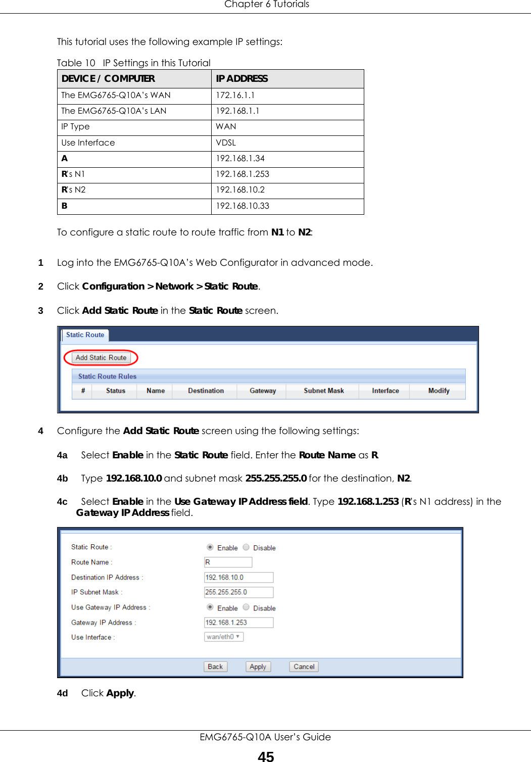
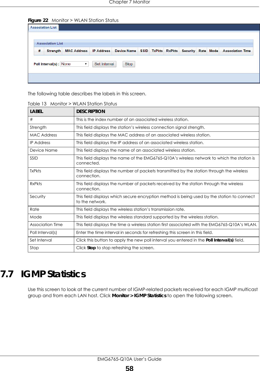
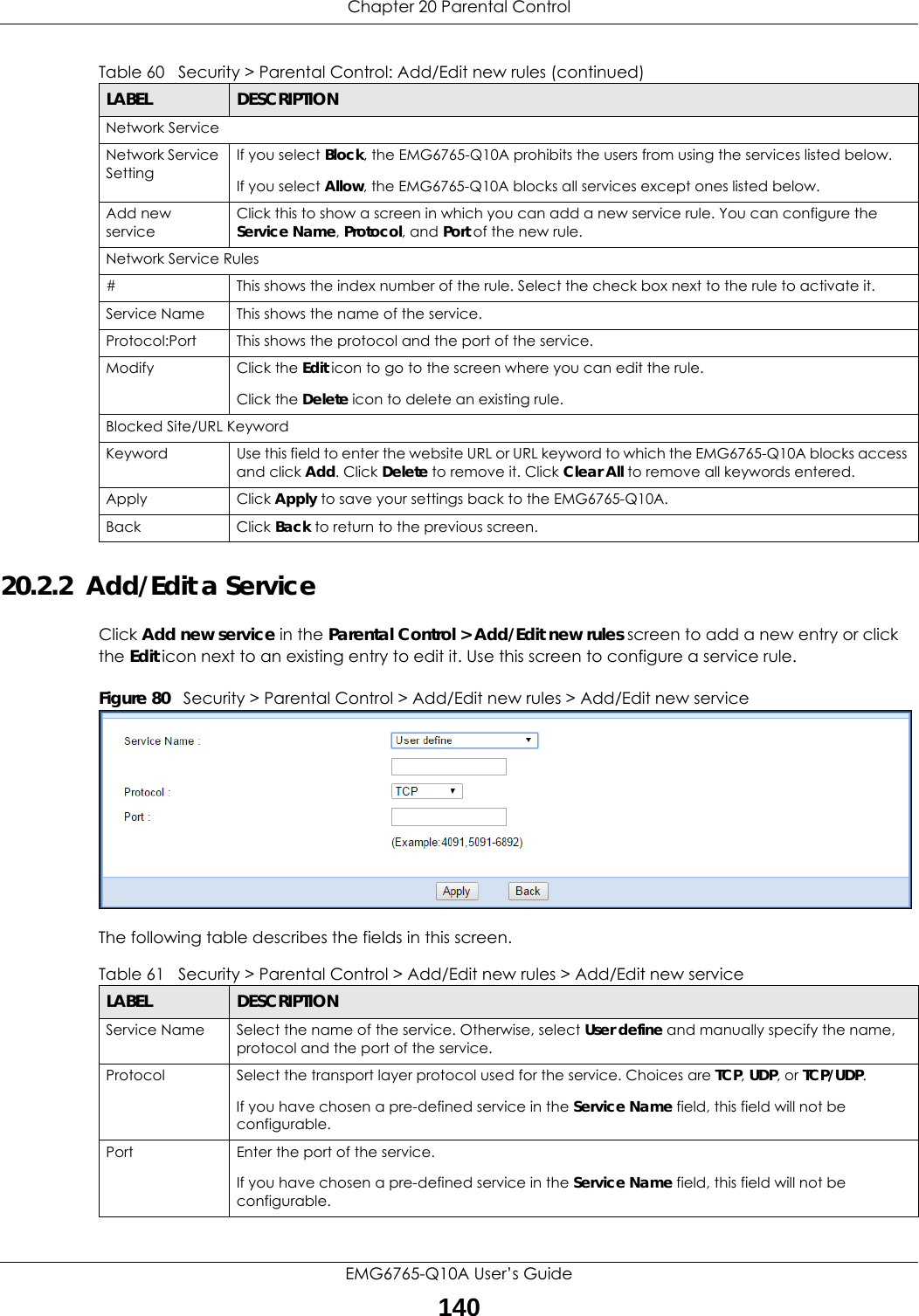
![Chapter 23 USB Media SharingEMG6765-Q10A User’s Guide1681In Windows Explorer’s Address bar type a double backslash “\\” followed by the IP address of the EMG6765-Q10A (the default IP address of the EMG6765-Q10A in router mode is 192.168.1.1) and press [ENTER]. A screen asking for password authentication appears. Type the user name and password (Bob and 1234 in this example) and click OK.Note: Once you log into the shared folder via your EMG6765-Q10A, you do not have to relogin unless you restart your computer.](https://usermanual.wiki/ZyXEL-Communications/EMG6765-Q10A/User-Guide-3484519-Page-168.png)
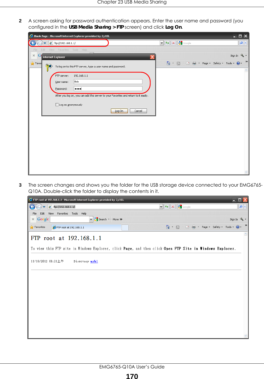
![Chapter 23 USB Media SharingEMG6765-Q10A User’s Guide1692You can also use the workgroup name to access files by browsing to the workgroup folder using the folder tree on the left side of the screen. It is located under My Network Places. In this example the workgroup name is the default “Workgroup”. 23.8.2 Use FTP to Share FilesYou can use FTP to access the USB storage devices connected to the EMG6765-Q10A. In this example, we use the web browser to share files via FTP from the LAN. The way or screen you log into the FTP server (on the EMG6765-Q10A) varies depending on your FTP client. See your FTP client documentation for more information. You should have enabled file sharing and create a user account (Bob/1234 for example) with read and write access to USB 1 in the USB Media Sharing > FTP screen.1In your web browser’s address or URL bar type “ftp://” followed by the IP address of the EMG6765-Q10A (the default LAN IP address of the EMG6765-Q10A in router mode is 192.168.1.1) and click Go or press [ENTER].](https://usermanual.wiki/ZyXEL-Communications/EMG6765-Q10A/User-Guide-3484519-Page-169.png)
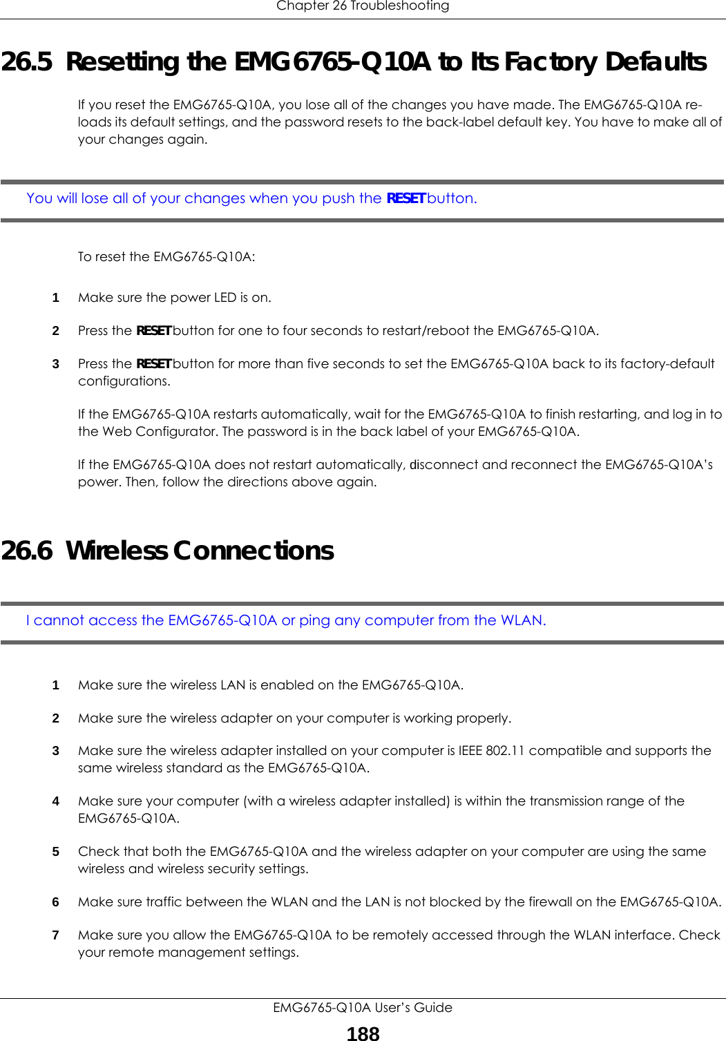
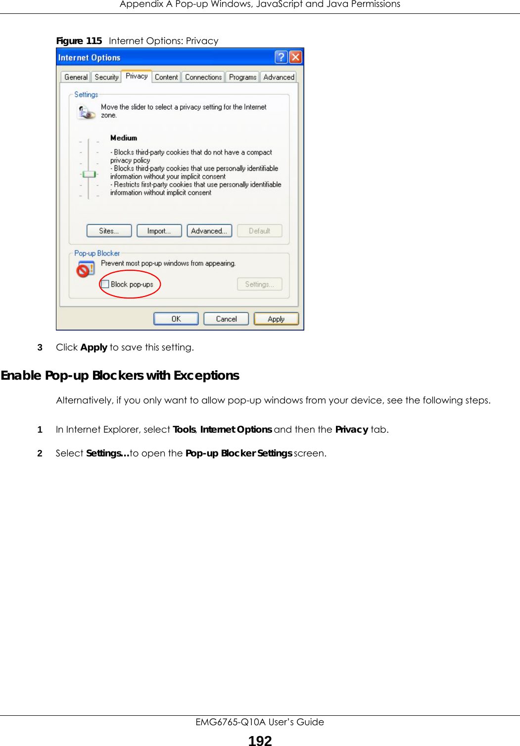
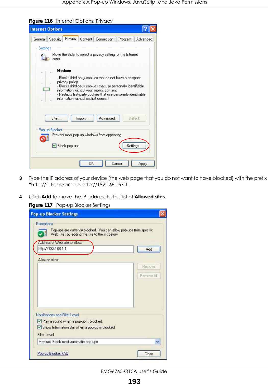
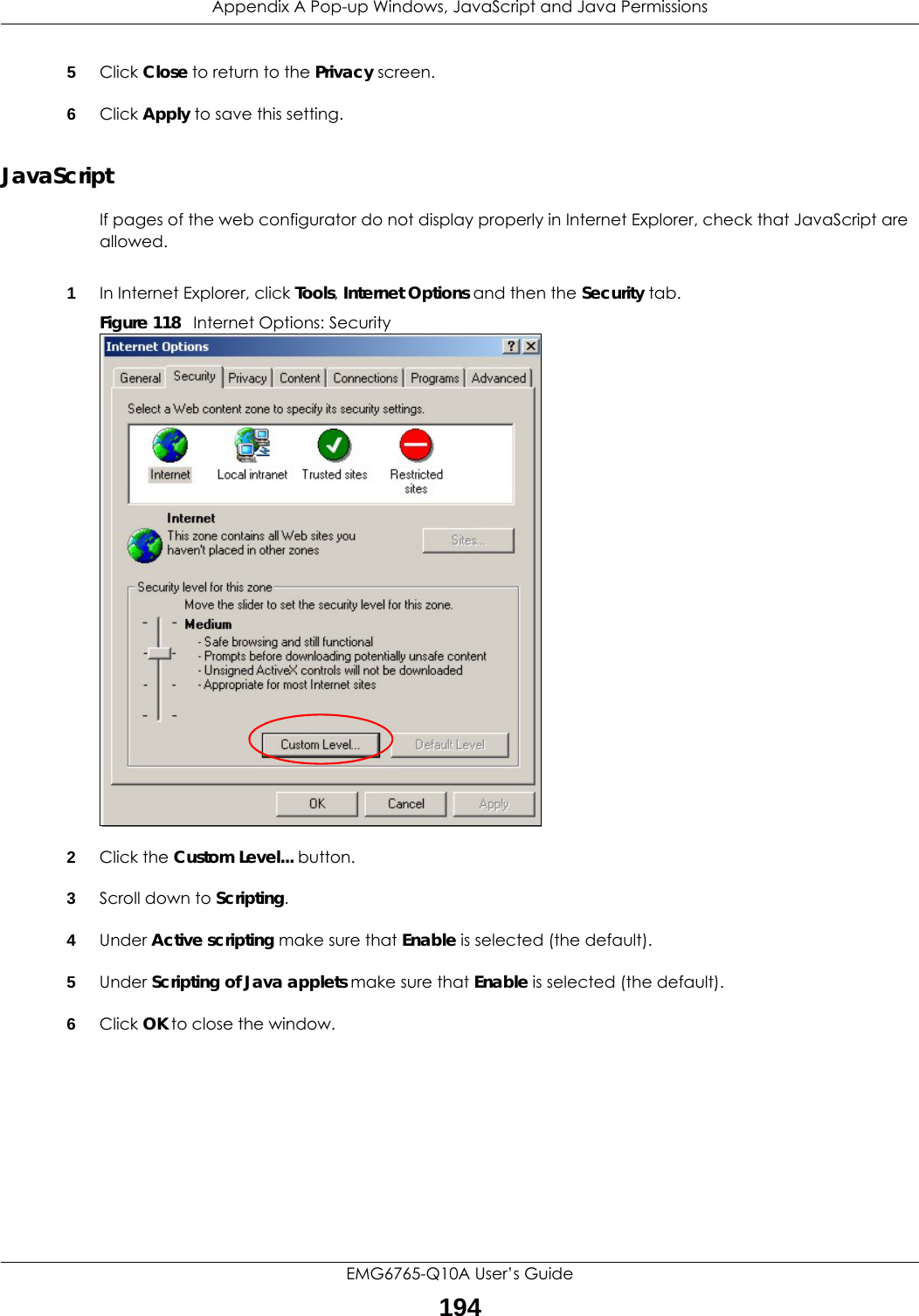
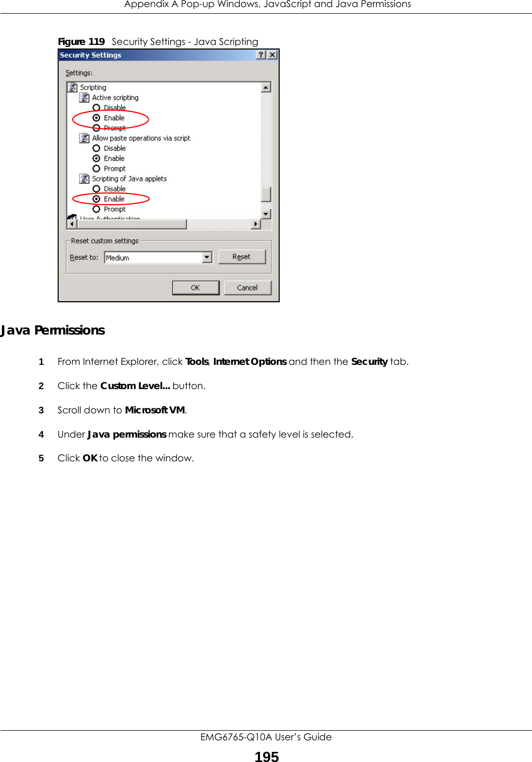
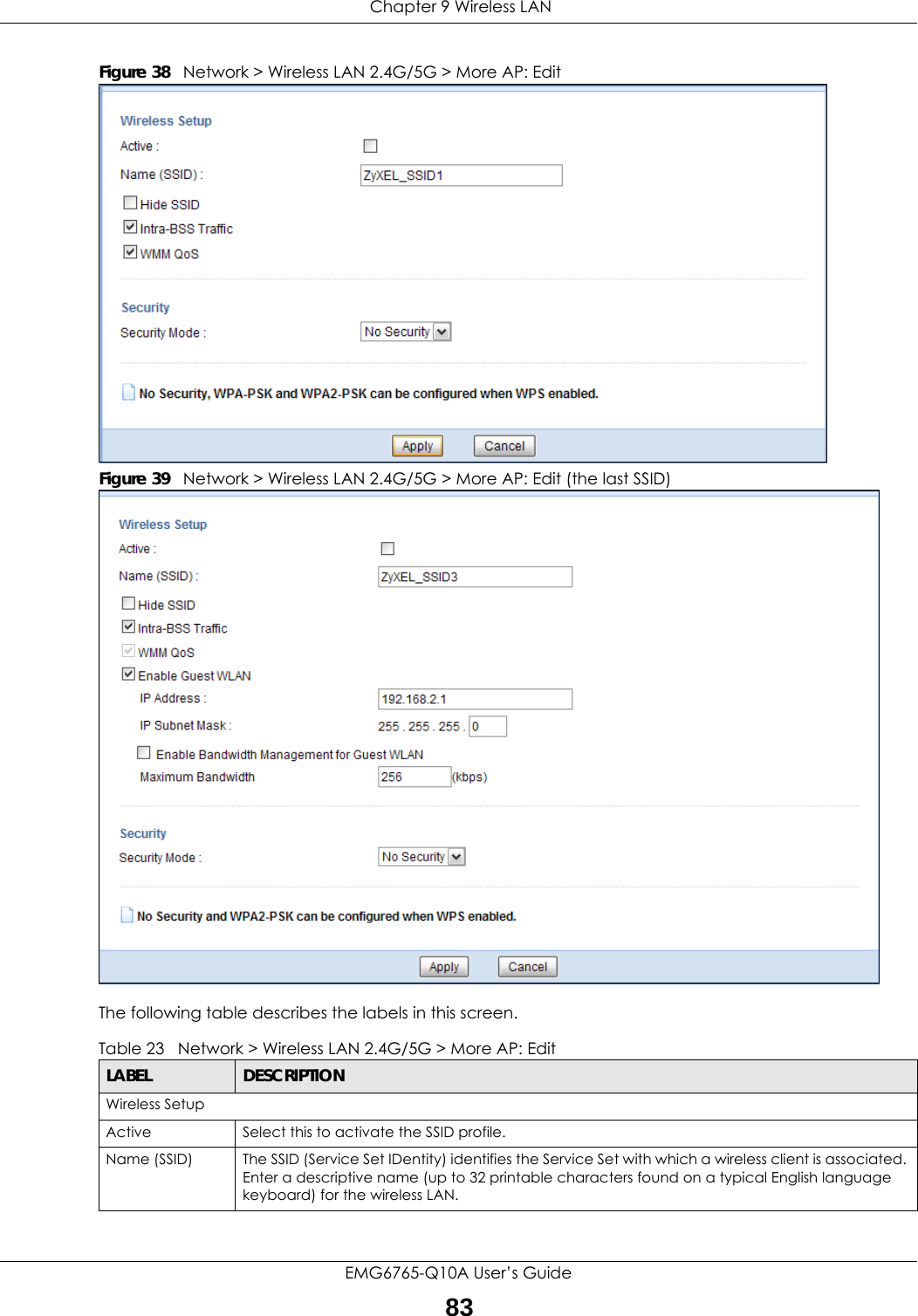
![Chapter 26 TroubleshootingEMG6765-Q10A User’s Guide1862Check the hardware connections, and make sure the LEDs are behaving as expected. See the Quick Start Guide. 3Make sure your Internet browser does not block pop-up windows and has JavaScript and Java enabled. See Appendix A on page 191.4Make sure your computer is in the same subnet as the EMG6765-Q10A. (If you know that there are routers between your computer and the EMG6765-Q10A, skip this step.)• If there is a DHCP server on your network, make sure your computer is using a dynamic IP address. See Section 10.4 on page 96. • If there is no DHCP server on your network, make sure your computer’s IP address is in the same subnet as the EMG6765-Q10A. See Section 10.4 on page 96.5Reset the device to its factory defaults, and try to access the EMG6765-Q10A with the default IP address. See Section 1.5 on page 14.6If the problem continues, contact the network administrator or vendor, or try one of the advanced suggestions.Advanced Suggestions• Try to access the EMG6765-Q10A using another service, such as Telnet. If you can access the EMG6765-Q10A, check the remote management settings and firewall rules to find out why the EMG6765-Q10A does not respond to HTTP.• If your computer is connected to the WAN port or is connected wirelessly, use a computer that is connected to a LAN/ETHERNET port.I can see the Login screen, but I cannot log in to the EMG6765-Q10A.1Make sure you have entered the password correctly. The default password is in the back label of your EMG6765-Q10A. This field is case-sensitive, so make sure [Caps Lock] is not on. 2This can happen when you fail to log out properly from your last session. Try logging in again after 5 minutes.3Disconnect and re-connect the power adaptor or cord to the EMG6765-Q10A. 4If this does not work, you have to reset the device to its factory defaults. See Section 26.5 on page 188.26.4 Internet AccessI cannot access the Internet.1Check the hardware connections, and make sure the LEDs are behaving as expected. See the Quick Start Guide.](https://usermanual.wiki/ZyXEL-Communications/EMG6765-Q10A/User-Guide-3484519-Page-186.png)
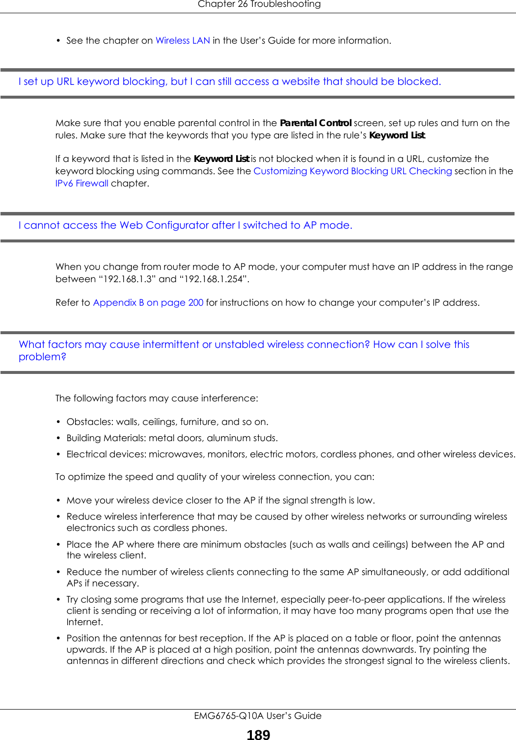
![Chapter 26 TroubleshootingEMG6765-Q10A User’s Guide1872Go to Maintenance > Sys OP Mode. Check your System Operation Mode setting. • If the EMG6765-Q10A is in Router Mode, make sure the WAN port is connected to a broadband modem or router with Internet access. Your computer and the EMG6765-Q10A should be in the same subnet.• If the EMG6765-Q10A is in Access Point Mode, make sure the WAN port is connected to a broadband modem or router with Internet access and your computer is set to obtain an dynamic IP address.3If the EMG6765-Q10A is in Router Mode, make sure you entered your ISP account information correctly in the wizard or the WAN screen. These fields are case-sensitive, so make sure [Caps Lock] is not on.4If you are trying to access the Internet wirelessly, make sure the wireless settings in the wireless client are the same as the settings in the AP.5Disconnect all the cables from your device, and follow the directions in the Quick Start Guide again. 6If the problem continues, contact your ISP.I cannot access the Internet anymore. I had access to the Internet (with the EMG6765-Q10A), but my Internet connection is not available anymore.1Check the hardware connections, and make sure the LEDs are behaving as expected. See the Quick Start Guide and Section 1.6 on page 15. 2Reboot the EMG6765-Q10A.3If the problem continues, contact your ISP. The Internet connection is slow or intermittent.1There might be a lot of traffic on the network. Look at the LEDs, and check Section 1.6 on page 15. If the EMG6765-Q10A is sending or receiving a lot of information, try closing some programs that use the Internet, especially peer-to-peer applications.2Check the signal strength. If the signal strength is low, try moving the EMG6765-Q10A closer to the AP if possible, and look around to see if there are any devices that might be interfering with the wireless network (for example, microwaves, other wireless networks, and so on).3Reboot the EMG6765-Q10A.4If the problem continues, contact the network administrator or vendor, or try one of the advanced suggestions.Advanced Suggestion• Check the settings for QoS. If it is disabled, you might consider activating it.](https://usermanual.wiki/ZyXEL-Communications/EMG6765-Q10A/User-Guide-3484519-Page-187.png)