ZyXEL Communications MAX206M1R WiMax MIMO CPE User Manual Quick Start Guide
ZyXEL Communications Corporation WiMax MIMO CPE Quick Start Guide
Contents
- 1. User Manual 1
- 2. User Manual 2
User Manual 2
Chapter 18 The Logs Screens
User’s Guide 201
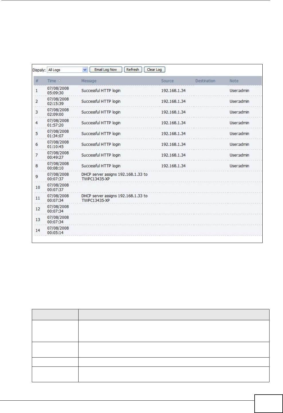
18.2 View Logs
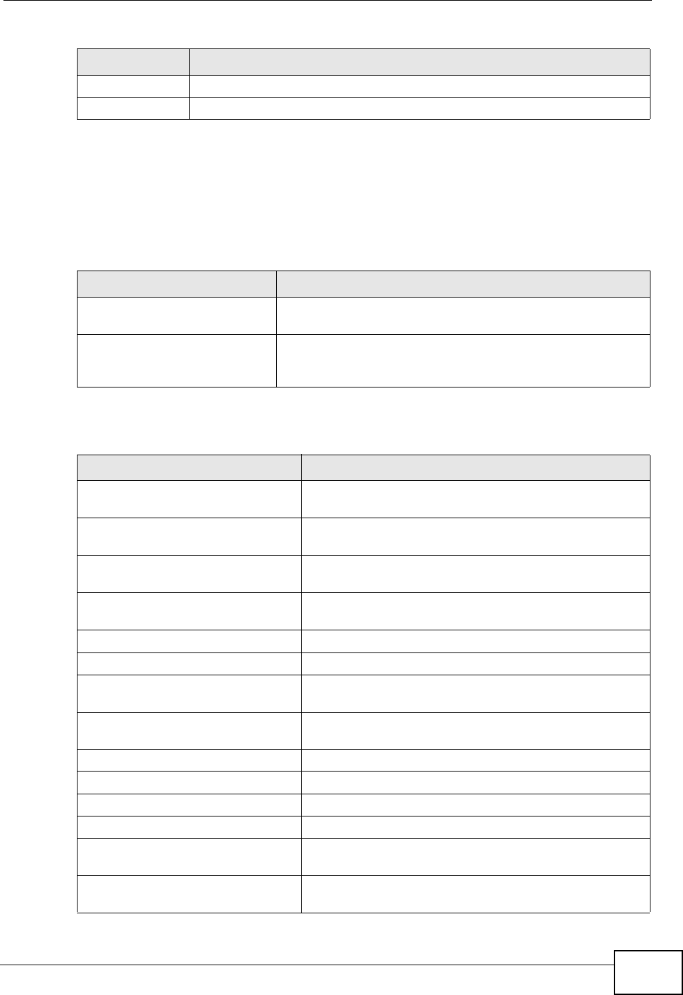
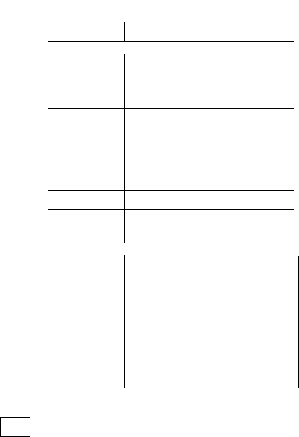
Click TOOLS > Logs > View Log to access this screen. Use this screen to look at
log entries and alerts. Alerts are written in red.
Figure 88 TOOLS > Logs > View Logs
Click a column header to sort log entries in descending (later-to-earlier) order.
Click again to sort in ascending order. The small triangle next to a column header
indicates how the table is currently sorted (pointing downward is descending;
pointing upward is ascending).
The following table describes the labels in this screen.
Table 77 TOOLS > Logs > View Logs
LABEL DESCRIPTION
Display Select a category whose log entries you want to view. To view all logs,
select All Logs. The list of categories depends on what log categories
are selected in the Log Settings page.
Email Log Now Click this to send the log screen to the e-mail address specified in the
Log Settings page.
Refresh Click to renew the log screen.
Clear Log Click to clear all the log entries, regardless of what is shown on the log
screen.
Chapter 18 The Logs Screens
User’s Guide
202
# The number of the item in this list.
Time This field displays the time the log entry was recorded.
Message This field displays the reason for the log entry. See Section 18.4 on
page 205.
Source This field displays the source IP address and the port number of the
incoming packet. In many cases, some or all of this information may
not be available.
Destination This field lists the destination IP address and the port number of the
incoming packet. In many cases, some or all of this information may
not be available.
Note This field displays additional information about the log entry.
Table 77 TOOLS > Logs > View Logs (continued)
LABEL DESCRIPTION
Chapter 18 The Logs Screens
User’s Guide 203
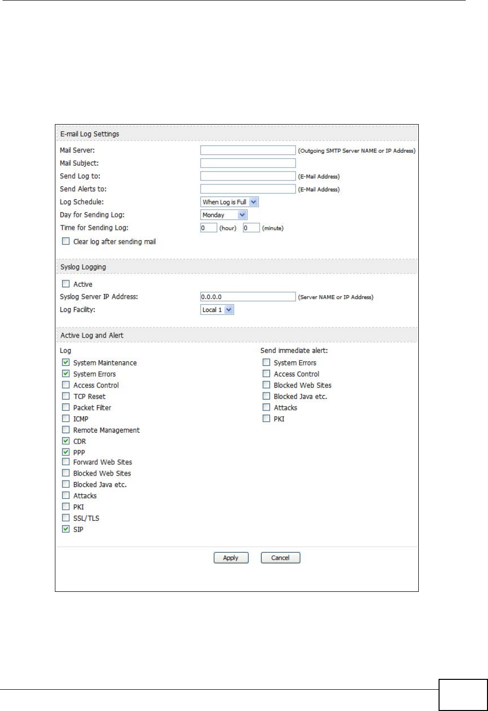
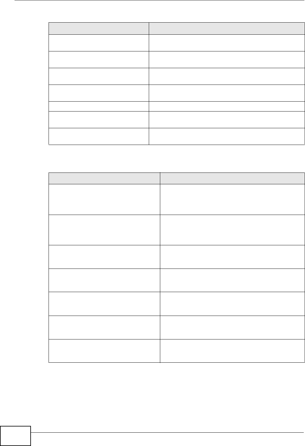
18.3 Log Settings
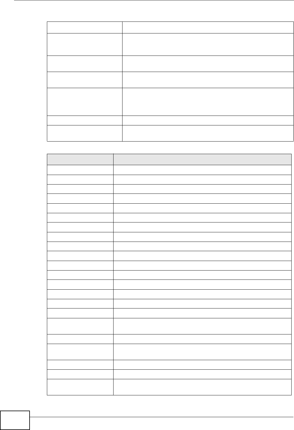
Click TOOLS > Logs > Log Settings to configure where the WiMAX Modem
sends logs and alerts, the schedule for sending logs, and which logs and alerts are
sent or recorded.
Figure 89 TOOLS > Logs > Log Settings
Chapter 18 The Logs Screens
User’s Guide
204
The following table describes the labels in this screen.
Table 78 TOOLS > Logs > Log Settings
LABEL DESCRIPTION
E-mail Log Settings
Mail Server Enter the server name or the IP address of the mail server the WiMAX
Modem should use to e-mail logs and alerts. Leave this field blank if you
do not want to send logs or alerts by e-mail.
Mail Subject Enter the subject line used in e-mail messages the WiMAX Modem
sends.
Send Log to Enter the e-mail address to which log entries are sent by e-mail. Leave
this field blank if you do not want to send logs by e-mail.
Send Alerts to Enter the e-mail address to which alerts are sent by e-mail. Leave this
field blank if you do not want to send alerts by e-mail.
Log Schedule Select the frequency with which the WiMAX Modem should send log
messages by e-mail.
• Daily
•Weekly
•Hourly
• When Log is Full
•None.
If the Weekly or the Daily option is selected, specify a time of day
when the E-mail should be sent. If the Weekly option is selected, then
also specify which day of the week the E-mail should be sent. If the
When Log is Full option is selected, an alert is sent when the log fills
up. If you select None, no log messages are sent.
Day for Sending
Log This field is only available when you select Weekly in the Log
Schedule field.
Select which day of the week to send the logs.
Time for
Sending Log This field is only available when you select Daily or Weekly in the Log
Schedule field.
Enter the time of day in 24-hour format (for example 23:00 equals
11:00 pm) to send the logs.
Clear log after
sending mail Select this to clear all logs and alert messages after logs are sent by e-
mail.
Syslog Logging
Active Select this to enable syslog logging.
Syslog Server
IP Address Enter the server name or IP address of the syslog server that logs the
selected categories of logs.
Log Facility Select a location. The log facility allows you to log the messages in
different files in the syslog server. See the documentation of your
syslog for more details.
Active Log and Alert
Log Select the categories of logs that you want to record.
Send
immediate alert Select the categories of alerts that you want the WiMAX Modem to send
immediately.
Chapter 18 The Logs Screens
User’s Guide 205
18.4 Log Message Descriptions
The following tables provide descriptions of example log messages.
Apply Click to save your changes.
Cancel Click to return to the previous screen without saving your changes.
Table 78 TOOLS > Logs > Log Settings
LABEL DESCRIPTION
Table 79 System Error Logs
LOG MESSAGE DESCRIPTION
WAN connection is down. The WAN connection is down. You cannot access the
network through this interface.
%s exceeds the max.
number of session per
host!
This attempt to create a NAT session exceeds the
maximum number of NAT session table entries allowed to
be created per host.
Table 80 System Maintenance Logs
LOG MESSAGE DESCRIPTION
Time calibration is
successful The device has adjusted its time based on information
from the time server.
Time calibration failed The device failed to get information from the time
server.
WAN interface gets IP: %s The WAN interface got a new IP address from the
DHCP or PPPoE server.
DHCP client gets %s A DHCP client got a new IP address from the DHCP
server.
DHCP client IP expired A DHCP client's IP address has expired.
DHCP server assigns %s The DHCP server assigned an IP address to a client.
Successful WEB login Someone has logged on to the device's web
configurator interface.
WEB login failed Someone has failed to log on to the device's web
configurator interface.
TELNET Login Successfully Someone has logged on to the router via telnet.
TELNET Login Fail Someone has failed to log on to the router via telnet.
Successful FTP login Someone has logged on to the device via ftp.
FTP login failed Someone has failed to log on to the device via ftp.
NAT Session Table is Full! The maximum number of NAT session table entries
has been exceeded and the table is full.
Time initialized by Daytime
Server The device got the time and date from the Daytime
server.
Chapter 18 The Logs Screens
User’s Guide
206
Time initialized by Time
server The device got the time and date from the time
server.
Time initialized by NTP
server The device got the time and date from the NTP
server.
Connect to Daytime server
fail The device was not able to connect to the Daytime
server.
Connect to Time server fail The device was not able to connect to the Time
server.
Connect to NTP server fail The device was not able to connect to the NTP server.
Too large ICMP packet has
been dropped The device dropped an ICMP packet that was too
large.
Configuration Change: PC =
0x%x, Task ID = 0x%x The device is saving configuration changes.
Table 81 Access Control Logs
LOG MESSAGE DESCRIPTION
Firewall default policy: [ TCP |
UDP | IGMP | ESP | GRE | OSPF ]
<Packet Direction>
Attempted TCP/UDP/IGMP/ESP/GRE/OSPF access
matched the default policy and was blocked or
forwarded according to the default policy’s
setting.
Firewall rule [NOT] match:[ TCP
| UDP | IGMP | ESP | GRE | OSPF
] <Packet Direction>, <rule:%d>
Attempted TCP/UDP/IGMP/ESP/GRE/OSPF access
matched (or did not match) a configured firewall
rule (denoted by its number) and was blocked or
forwarded according to the rule.
Triangle route packet forwarded:
[ TCP | UDP | IGMP | ESP | GRE |
OSPF ]
The firewall allowed a triangle route session to
pass through.
Packet without a NAT table entry
blocked: [ TCP | UDP | IGMP |
ESP | GRE | OSPF ]
The router blocked a packet that didn't have a
corresponding NAT table entry.
Router sent blocked web site
message: TCP The router sent a message to notify a user that
the router blocked access to a web site that the
user requested.
Exceed maximum sessions per host
(%d). The device blocked a session because the host's
connections exceeded the maximum sessions per
host.
Firewall allowed a packet that
matched a NAT session: [ TCP |
UDP ]
A packet from the WAN (TCP or UDP) matched a
cone NAT session and the device forwarded it to
the LAN.
Table 80 System Maintenance Logs (continued)
LOG MESSAGE DESCRIPTION

Chapter 18 The Logs Screens
User’s Guide 207
Table 82 TCP Reset Logs
LOG MESSAGE DESCRIPTION
Under SYN flood attack,
sent TCP RST The router sent a TCP reset packet when a host was
under a SYN flood attack (the TCP incomplete count is per
destination host.)
Exceed TCP MAX
incomplete, sent TCP RST The router sent a TCP reset packet when the number of
TCP incomplete connections exceeded the user configured
threshold. (the TCP incomplete count is per destination
host.)
Peer TCP state out of
order, sent TCP RST The router sent a TCP reset packet when a TCP
connection state was out of order.Note: The firewall
refers to RFC793 Figure 6 to check the TCP state.
Firewall session time
out, sent TCP RST The router sent a TCP reset packet when a dynamic
firewall session timed out.
The default timeout values are as follows:
ICMP idle timeout: 3 minutes
UDP idle timeout: 3 minutes
TCP connection (three way handshaking) timeout: 270
seconds
TCP FIN-wait timeout: 2 MSL (Maximum Segment
Lifetime set in the TCP header).
TCP idle (established) timeout (s): 150 minutes
TCP reset timeout: 10 seconds
Exceed MAX incomplete,
sent TCP RST The router sent a TCP reset packet when the number of
incomplete connections (TCP and UDP) exceeded the
user-configured threshold. (Incomplete count is for all
TCP and UDP connections through the firewall.)Note:
When the number of incomplete connections (TCP + UDP)
> “Maximum Incomplete High”, the router sends TCP RST
packets for TCP connections and destroys TOS (firewall
dynamic sessions) until incomplete connections <
“Maximum Incomplete Low”.
Access block, sent TCP
RST The router sends a TCP RST packet and generates this log
if you turn on the firewall TCP reset mechanism (via CI
command: sys firewall tcprst).
Table 83 Packet Filter Logs
LOG MESSAGE DESCRIPTION
[ TCP | UDP | ICMP | IGMP |
Generic ] packet filter
matched (set: %d, rule: %d)
Attempted access matched a configured filter rule
(denoted by its set and rule number) and was blocked
or forwarded according to the rule.
Chapter 18 The Logs Screens
User’s Guide
208
For type and code details, see Table 90 on page 211.
Table 84 ICMP Logs
LOG MESSAGE DESCRIPTION
Firewall default policy: ICMP
<Packet Direction>, <type:%d>,
<code:%d>
ICMP access matched the default policy and was
blocked or forwarded according to the user's
setting.
Firewall rule [NOT] match: ICMP
<Packet Direction>, <rule:%d>,
<type:%d>, <code:%d>
ICMP access matched (or didn’t match) a firewall
rule (denoted by its number) and was blocked or
forwarded according to the rule.
Triangle route packet forwarded:
ICMP The firewall allowed a triangle route session to
pass through.
Packet without a NAT table entry
blocked: ICMP The router blocked a packet that didn’t have a
corresponding NAT table entry.
Unsupported/out-of-order ICMP:
ICMP The firewall does not support this kind of ICMP
packets or the ICMP packets are out of order.
Router reply ICMP packet: ICMP The router sent an ICMP reply packet to the
sender.
Table 85 PPP Logs
LOG MESSAGE DESCRIPTION
ppp:LCP Starting The PPP connection’s Link Control Protocol stage has started.
ppp:LCP Opening The PPP connection’s Link Control Protocol stage is opening.
ppp:CHAP Opening The PPP connection’s Challenge Handshake Authentication Protocol
stage is opening.
ppp:IPCP
Starting The PPP connection’s Internet Protocol Control Protocol stage is
starting.
ppp:IPCP Opening The PPP connection’s Internet Protocol Control Protocol stage is
opening.
ppp:LCP Closing The PPP connection’s Link Control Protocol stage is closing.
ppp:IPCP Closing The PPP connection’s Internet Protocol Control Protocol stage is
closing.
Table 86 UPnP Logs
LOG MESSAGE DESCRIPTION
UPnP pass through Firewall UPnP packets can pass through the firewall.
Chapter 18 The Logs Screens
User’s Guide 209
For type and code details, see Table 90 on page 211.
Table 87 Content Filtering Logs
LOG MESSAGE DESCRIPTION
%s: Keyword blocking The content of a requested web page matched a user defined
keyword.
%s: Not in trusted web
list The web site is not in a trusted domain, and the router blocks
all traffic except trusted domain sites.
%s: Forbidden Web site The web site is in the forbidden web site list.
%s: Contains ActiveX The web site contains ActiveX.
%s: Contains Java
applet The web site contains a Java applet.
%s: Contains cookie The web site contains a cookie.
%s: Proxy mode
detected The router detected proxy mode in the packet.
%s: Trusted Web site The web site is in a trusted domain.
%s When the content filter is not on according to the time
schedule:
Waiting content
filter server
timeout
The external content filtering server did not respond within
the timeout period.
DNS resolving
failed The WiMAX Modem cannot get the IP address of the external
content filtering via DNS query.
Creating socket
failed The WiMAX Modem cannot issue a query because TCP/UDP
socket creation failed, port:port number.
Connecting to
content filter
server fail
The connection to the external content filtering server failed.
License key is
invalid The external content filtering license key is invalid.
Table 88 Attack Logs
LOG MESSAGE DESCRIPTION
attack [ TCP | UDP | IGMP
| ESP | GRE | OSPF ] The firewall detected a TCP/UDP/IGMP/ESP/GRE/OSPF
attack.
attack ICMP (type:%d,
code:%d) The firewall detected an ICMP attack.
land [ TCP | UDP | IGMP |
ESP | GRE | OSPF ] The firewall detected a TCP/UDP/IGMP/ESP/GRE/OSPF
land attack.
land ICMP (type:%d,
code:%d) The firewall detected an ICMP land attack.
ip spoofing - WAN [ TCP |
UDP | IGMP | ESP | GRE |
OSPF ]
The firewall detected an IP spoofing attack on the WAN
port.
Chapter 18 The Logs Screens
User’s Guide
210
ip spoofing - WAN ICMP
(type:%d, code:%d) The firewall detected an ICMP IP spoofing attack on the
WAN port.
icmp echo : ICMP
(type:%d, code:%d) The firewall detected an ICMP echo attack.
syn flood TCP The firewall detected a TCP syn flood attack.
ports scan TCP The firewall detected a TCP port scan attack.
teardrop TCP The firewall detected a TCP teardrop attack.
teardrop UDP The firewall detected an UDP teardrop attack.
teardrop ICMP (type:%d,
code:%d) The firewall detected an ICMP teardrop attack.
illegal command TCP The firewall detected a TCP illegal command attack.
NetBIOS TCP The firewall detected a TCP NetBIOS attack.
ip spoofing - no routing
entry [ TCP | UDP | IGMP
| ESP | GRE | OSPF ]
The firewall classified a packet with no source routing
entry as an IP spoofing attack.
ip spoofing - no routing
entry ICMP (type:%d,
code:%d)
The firewall classified an ICMP packet with no source
routing entry as an IP spoofing attack.
vulnerability ICMP
(type:%d, code:%d) The firewall detected an ICMP vulnerability attack.
traceroute ICMP (type:%d,
code:%d) The firewall detected an ICMP traceroute attack.
ports scan UDP The firewall detected a UDP port scan attack.
Firewall sent TCP packet
in response to DoS attack
TCP
The firewall sent TCP packet in response to a DoS attack
ICMP Source Quench ICMP The firewall detected an ICMP Source Quench attack.
ICMP Time Exceed ICMP The firewall detected an ICMP Time Exceed attack.
ICMP Destination
Unreachable ICMP The firewall detected an ICMP Destination Unreachable
attack.
ping of death. ICMP The firewall detected an ICMP ping of death attack.
smurf ICMP The firewall detected an ICMP smurf attack.
Table 89 Remote Management Logs
LOG MESSAGE DESCRIPTION
Remote Management: FTP denied Attempted use of FTP service was blocked according
to remote management settings.
Remote Management: TELNET
denied Attempted use of TELNET service was blocked
according to remote management settings.
Remote Management: HTTP or
UPnP denied Attempted use of HTTP or UPnP service was blocked
according to remote management settings.
Table 88 Attack Logs (continued)
LOG MESSAGE DESCRIPTION

Chapter 18 The Logs Screens
User’s Guide 211
Remote Management: WWW denied Attempted use of WWW service was blocked
according to remote management settings.
Remote Management: HTTPS
denied Attempted use of HTTPS service was blocked
according to remote management settings.
Remote Management: SSH denied Attempted use of SSH service was blocked
according to remote management settings.
Remote Management: ICMP Ping
response denied Attempted use of ICMP service was blocked
according to remote management settings.
Remote Management: DNS denied Attempted use of DNS service was blocked
according to remote management settings.
Table 90 ICMP Notes
TYPE CODE DESCRIPTION
0Echo Reply
0Echo reply message
3Destination Unreachable
0Net unreachable
1Host unreachable
2Protocol unreachable
3Port unreachable
4A packet that needed fragmentation was dropped because it was set
to Don't Fragment (DF)
5Source route failed
4Source Quench
0A gateway may discard internet datagrams if it does not have the
buffer space needed to queue the datagrams for output to the next
network on the route to the destination network.
5Redirect
0Redirect datagrams for the Network
1Redirect datagrams for the Host
2Redirect datagrams for the Type of Service and Network
3Redirect datagrams for the Type of Service and Host
8Echo
0Echo message
11 Time Exceeded
0Time to live exceeded in transit
1Fragment reassembly time exceeded
12 Parameter Problem
0Pointer indicates the error
13 Timestamp
Table 89 Remote Management Logs
LOG MESSAGE DESCRIPTION
Chapter 18 The Logs Screens
User’s Guide
212
0Timestamp request message
14 Timestamp Reply
0Timestamp reply message
15 Information Request
0Information request message
16 Information Reply
0Information reply message
Table 91 SIP Logs
LOG MESSAGE DESCRIPTION
SIP Registration Success
by SIP:SIP Phone Number The listed SIP account was successfully registered with a
SIP register server.
SIP Registration Fail by
SIP:SIP Phone Number An attempt to register the listed SIP account with a SIP
register server was not successful.
SIP UnRegistration
Success by SIP:SIP Phone
Number
The listed SIP account’s registration was deleted from
the SIP register server.
SIP UnRegistration Fail
by SIP:SIP Phone Number An attempt to delete the listed SIP account’s registration
from the SIP register server failed.
Table 92 RTP Logs
LOG MESSAGE DESCRIPTION
Error, RTP init fail The initialization of an RTP session failed.
Error, Call fail: RTP
connect fail A VoIP phone call failed because the RTP session could
not be established.
Error, RTP connection
cannot close The termination of an RTP session failed.
Table 90 ICMP Notes (continued)
TYPE CODE DESCRIPTION
Chapter 18 The Logs Screens
User’s Guide 213
Table 93 FSM Logs: Caller Side
LOG MESSAGE DESCRIPTION
VoIP Call Start Ph[Phone
Port Number] <- Outgoing
Call Number
Someone used a phone connected to the listed phone
port to initiate a VoIP call to the listed destination.
VoIP Call Established
Ph[Phone Port] ->
Outgoing Call Number
Someone used a phone connected to the listed phone
port to make a VoIP call to the listed destination.
VoIP Call End Phone[Phone
Port] A VoIP phone call made from a phone connected to the
listed phone port has terminated.
Table 94 FSM Logs: Callee Side
LOG MESSAGE DESCRIPTION
VoIP Call Start from
SIP[SIP Port Number] A VoIP phone call came to the WiMAX Modem from the
listed SIP number.
VoIP Call Established
Ph[Phone Port] <-
Outgoing Call Number
A VoIP phone call was set up from the listed SIP number to
the WiMAX Modem.
VoIP Call End
Phone[Phone Port] A VoIP phone call that came into the WiMAX Modem has
terminated.
Table 95 Lifeline Logs
LOG MESSAGE DESCRIPTION
PSTN Call Start A PSTN call has been initiated.
PSTN Call End A PSTN call has terminated.
PSTN Call Established A PSTN call has been set up.

Chapter 18 The Logs Screens
User’s Guide
214
User’s Guide 215
CHAPTER 19
The Status Screen
19.1 Overview
Use this screen to view a complete summary of your WiMAX Modem connection
status.
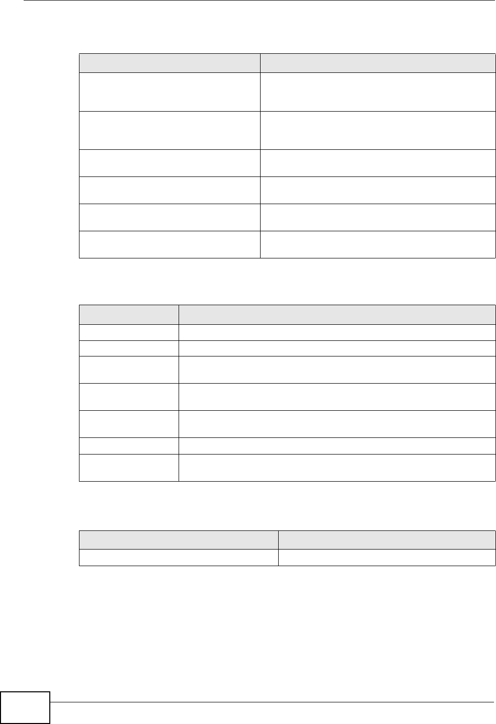
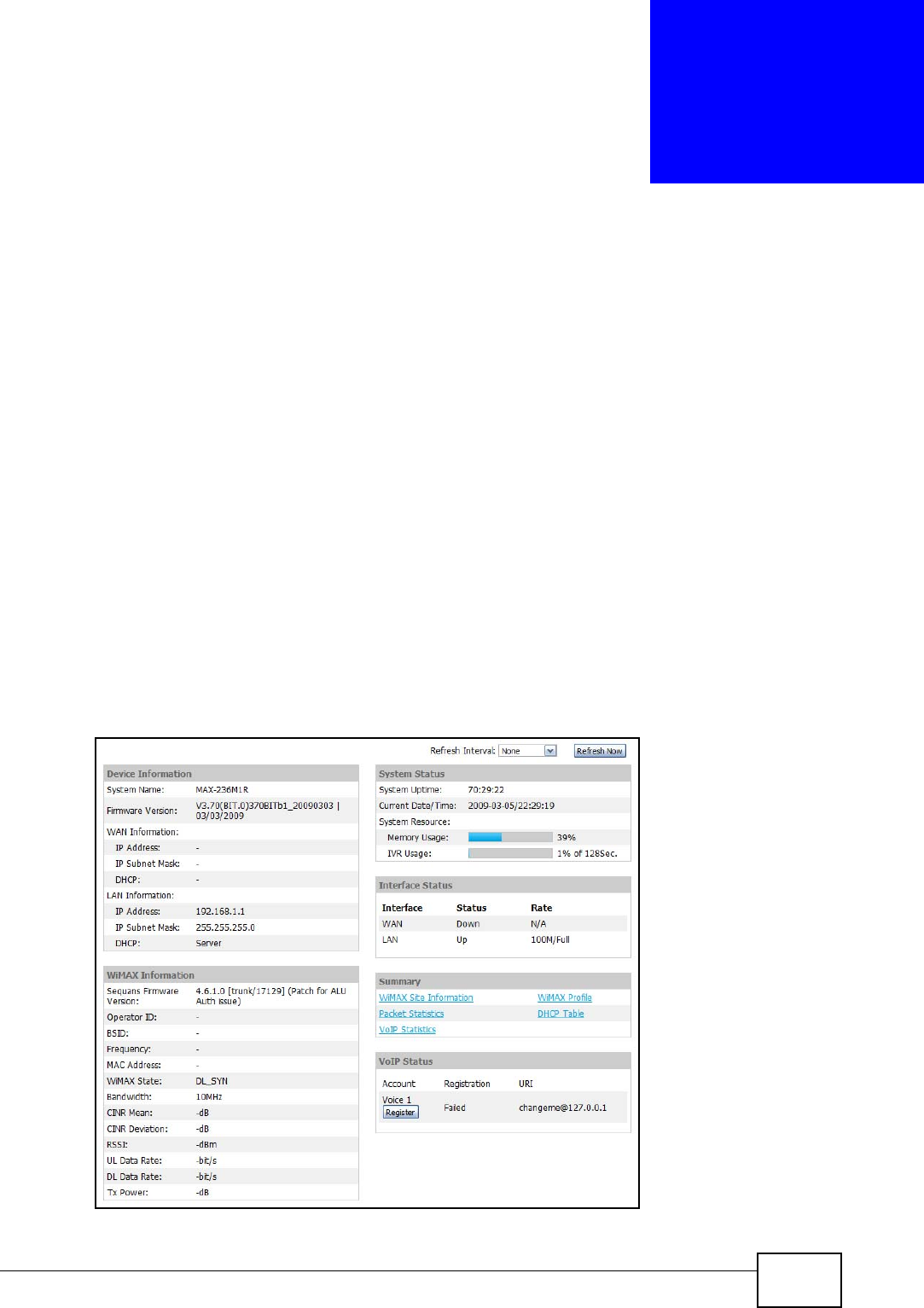
19.2 Status Screen
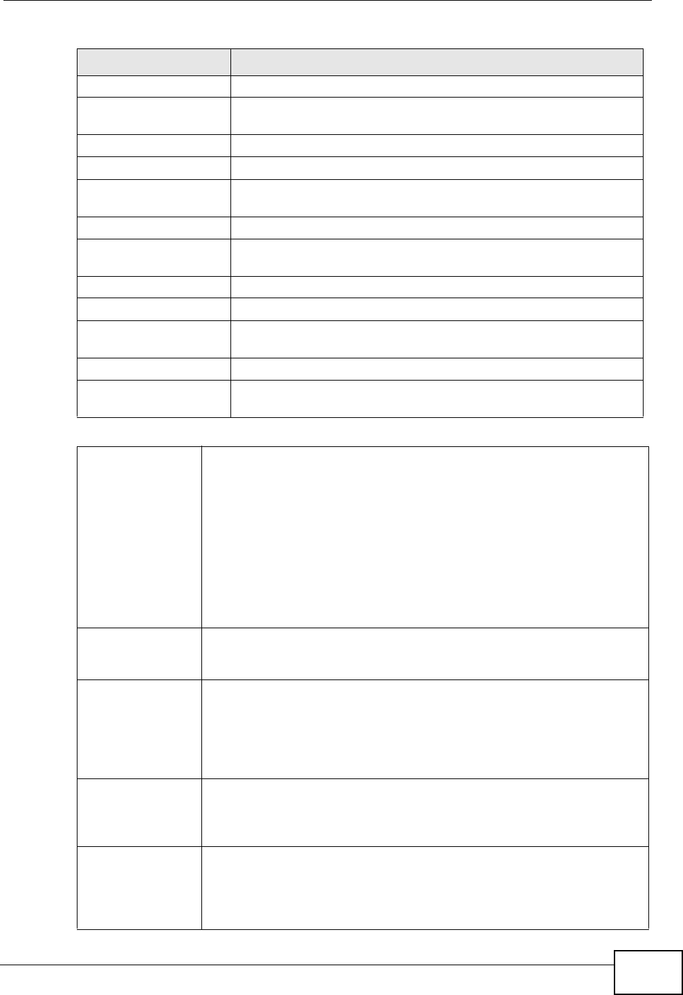
Click the STATUS icon in the navigation bar to go to this screen, where you can
view the current status of the device, system resources, interfaces (LAN and
WAN), and SIP accounts. You can also register and un-register SIP accounts as
well as view detailed information from DHCP and statistics from WiMAX, VoIP,
bandwidth management, and traffic.
Figure 90 Status
Chapter 19 The Status Screen
User’s Guide
216
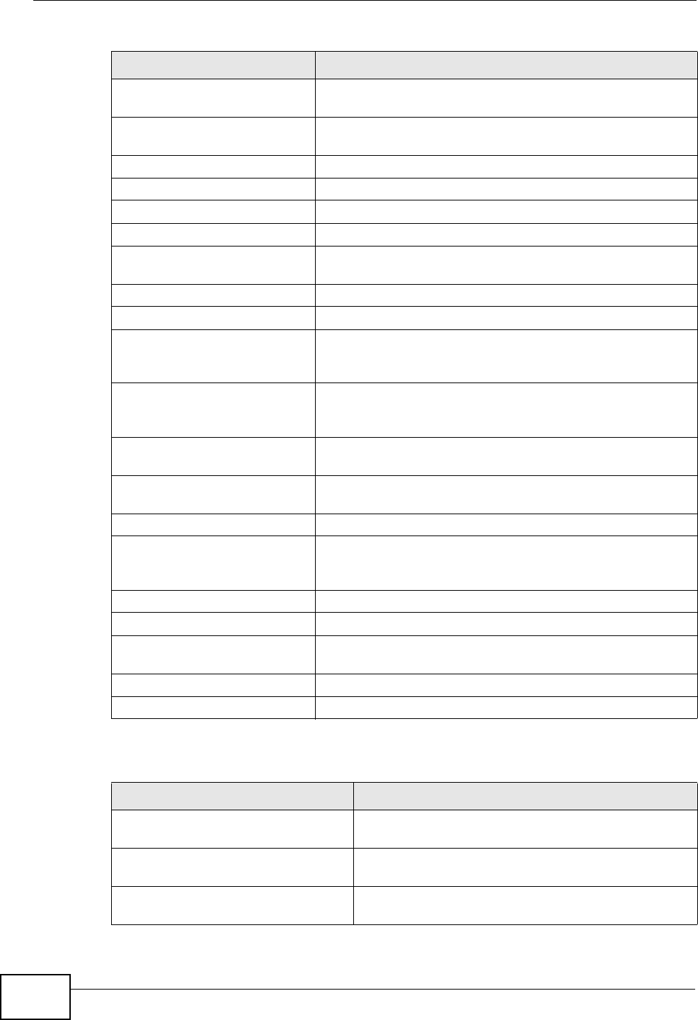
The following tables describe the labels in this screen.
Table 96 Status
LABEL DESCRIPTION
Refresh Interval Select how often you want the WiMAX Modem to update this screen.
Refresh Now Click this to update this screen immediately.
Device Information
System Name This field displays the WiMAX Modem system name. It is used for
identification.
You can change this in the ADVANCED > System Configuration >
General screen’s System Name field.
Firmware
Version This field displays the current version of the firmware inside the device.
It also shows the date the firmware version was created.
You can change the firmware version by uploading new firmware in
ADVANCED > System Configuration > Firmware.
WAN Information
IP Address This field displays the current IP address of the WiMAX Modem in the
WAN.
IP Subnet Mask This field displays the current subnet mask on the WAN.
DHCP This field displays what DHCP services the WiMAX Modem is using in the
WAN. Choices are:
Client - The WiMAX Modem is a DHCP client in the WAN. Its IP
address comes from a DHCP server on the WAN.
None - The WiMAX Modem is not using any DHCP services in the
WAN. It has a static IP address.
LAN Information
IP Address This field displays the current IP address of the WiMAX Modem in the
LAN.
IP Subnet Mask This field displays the current subnet mask in the LAN.
DHCP This field displays what DHCP services the WiMAX Modem is providing
to the LAN. Choices are:
Server - The WiMAX Modem is a DHCP server in the LAN. It assigns
IP addresses to other computers in the LAN.
Relay - The WiMAX Modem is routing DHCP requests to one or more
DHCP servers. The DHCP server(s) may be on another network.
None - The WiMAX Modem is not providing any DHCP services to the
LAN.
You can change this in ADVANCED > LAN Configuration > DHCP
Setup.
WiMAX Information
Operator ID Every WiMAX service provider has a unique Operator ID number, which
is broadcast by each base station it owns. You can only connect to the
Internet through base stations belonging to your service provider’s
network.
BSID This field displays the identification number of the wireless base station
to which the WiMAX Modem is connected. Every base station transmits
a unique BSID, which identifies it across the network.

Chapter 19 The Status Screen
User’s Guide 217
Frequency This field displays the radio frequency of the WiMAX Modem’s wireless
connection to a base station.
MAC address This field displays the Media Access Control address of the WiMAX
Modem. Every network device has a unique MAC address which
identifies it across the network.
WiMAX State This field displays the status of the WiMAX Modem’s current connection.
•INIT: the WiMAX Modem is starting up.
•DL_SYN: The WiMAX Modem is unable to connect to a base station.
•RANGING: the WiMAX Modem and the base station are transmitting
and receiving information about the distance between them.
Ranging allows the WiMAX Modem to use a lower transmission
power level when communicating with a nearby base station, and a
higher transmission power level when communicating with a distant
base station.
•CAP_NEGO: the WiMAX Modem and the base station are
exchanging information about their capabilities.
•AUTH: the WiMAX Modem and the base station are exchanging
security information.
•REGIST: the WiMAX Modem is registering with a RADIUS server.
•OPERATIONAL: the WiMAX Modem has successfully registered with
the base station. Traffic can now flow between the WiMAX Modem
and the base station.
•IDLE: the WiMAX Modem is in power saving mode, but can connect
when a base station alerts it that there is traffic waiting.
Bandwidth This field shows the size of the bandwidth step the WiMAX Modem uses
to connect to a base station in megahertz (MHz).
CINR mean This field shows the average Carrier to Interference plus Noise Ratio of
the current connection. This value is an indication of overall radio signal
quality. A higher value indicates a higher signal quality, and a lower
value indicates a lower signal quality.
CINR deviation This field shows the amount of change in the CINR level. This value is
an indication of radio signal stability. A lower number indicates a more
stable signal, and a higher number indicates a less stable signal.
RSSI This field shows the Received Signal Strength Indication. This value is a
measurement of overall radio signal strength. A higher RSSI level
indicates a stronger signal, and a lower RSSI level indicates a weaker
signal.
A strong signal does not necessarily indicate a good signal: a strong
signal may have a low signal-to-noise ratio (SNR).
UL Data Rate This field shows the number of data packets uploaded from the WiMAX
Modem to the base station each second.
DL Data Rate This field shows the number of data packets downloaded to the WiMAX
Modem from the base station each second.
Tx Power This field shows the output transmission (Tx) level of the WiMAX
Modem.
System Status
Table 96 Status (continued)
LABEL DESCRIPTION
Chapter 19 The Status Screen
User’s Guide
218
System Uptime This field displays how long the WiMAX Modem has been running since
it last started up. The WiMAX Modem starts up when you plug it in,
when you restart it (ADVANCED > System Configuration >
Restart), or when you reset it.
Current Date/
Time This field displays the current date and time in the WiMAX Modem. You
can change this in SETUP > Time Setting.
Memory Usage This field displays what percentage of the WiMAX Modem’s memory is
currently used. The higher the memory usage, the more likely the
WiMAX Modem is to slow down. Some memory is required just to start
the WiMAX Modem and to run the web configurator. You can reduce the
memory usage by disabling some services (see CPU Usage); by
reducing the amount of memory allocated to NAT and firewall rules (you
may have to reduce the number of NAT rules or firewall rules to do so);
or by deleting rules in functions such as incoming call policies, speed
dial entries, and static routes.
IVR Usage This field displays what percentage of the WiMAX Modem’s IVR memory
is currently used. IVR (Interactive Voice Response) refers to the
customizable ring tone and on-hold music you set.
Interface Status
Interface This column displays each interface of the WiMAX Modem.
Status This field indicates whether or not the WiMAX Modem is using the
interface.
For the WAN interface, this field displays Up when the WiMAX Modem is
connected to a WiMAX network, and Down when the WiMAX Modem is
not connected to a WiMAX network.
For the LAN interface, this field displays Up when the WiMAX Modem is
using the interface and Down when the WiMAX Modem is not using the
interface.
Rate For the LAN ports this displays the port speed and duplex setting.
For the WAN interface, it displays the downstream and upstream
transmission rate or N/A if the WiMAX Modem is not connected to a
base station.
For the WLAN interface, it displays the transmission rate when WLAN is
enabled or N/A when WLAN is disabled.
Summary
Packet
Statistics Click this link to view port status and packet specific statistics.
WiMAX Site
Information Click this link to view details of the radio frequencies used by the
WiMAX Modem to connect to a base station.
DHCP Table Click this link to see details of computers to which the WiMAX Modem
has given an IP address.
VoIP Statistics Click this link to view statistics about your VoIP usage.
WiMAX Profile Click this link to view details of the current wireless security settings.
VoIP Status
Account This column displays each SIP account in the WiMAX Modem.
Table 96 Status (continued)
LABEL DESCRIPTION
Chapter 19 The Status Screen
User’s Guide 219
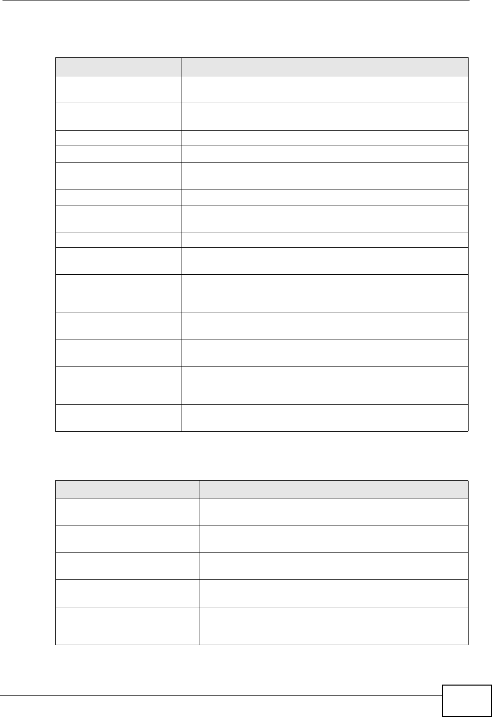
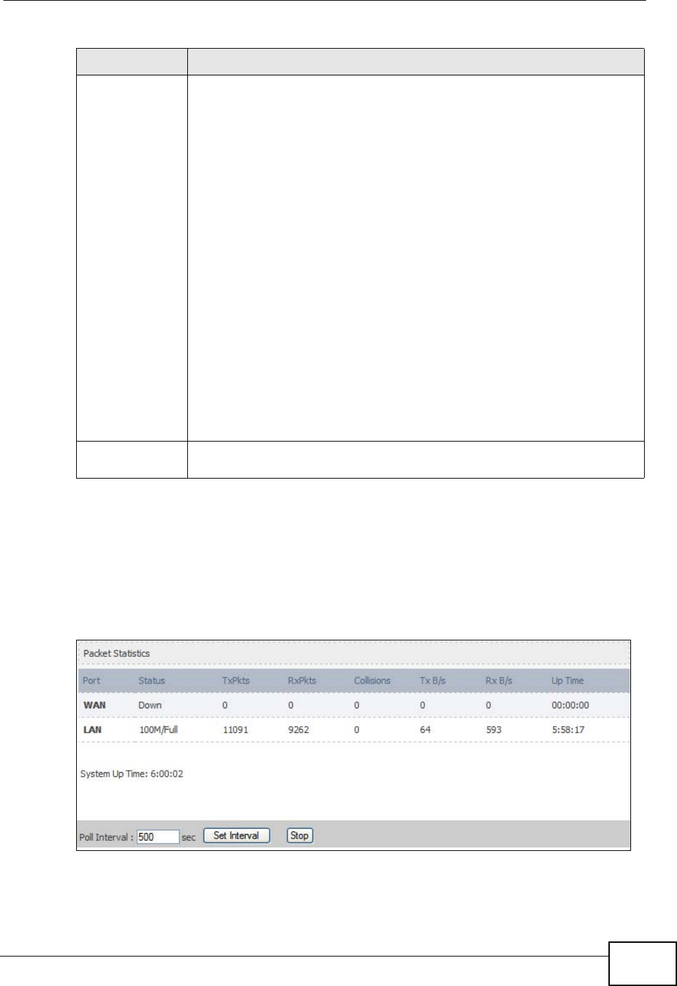
19.2.1 Packet Statistics
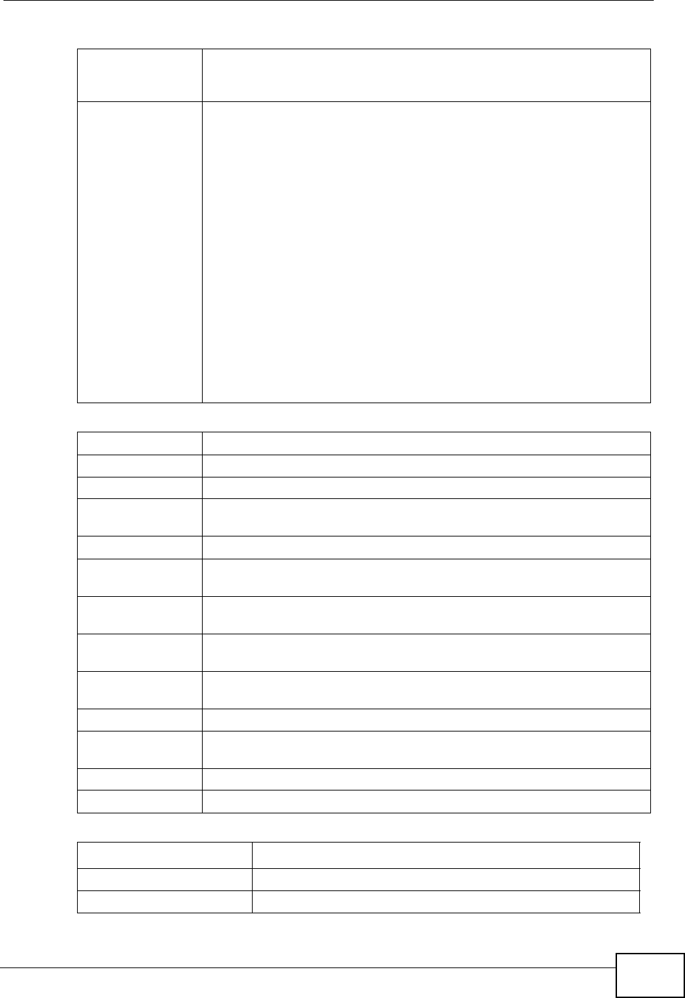
Click Status > Packet Statistics to open this screen. This read-only screen
displays information about the data transmission through the WiMAX Modem. To
configure these settings, go to the corresponding area in the Advanced screens.
Figure 91 Packet Statistics
Registration This field displays the current registration status of the SIP account.
You have to register SIP accounts with a SIP server to use VoIP.
If the SIP account is already registered with the SIP server,
Click Unregister to delete the SIP account’s registration in the SIP
server. This does not cancel your SIP account, but it deletes the
mapping between your SIP identity and your IP address or domain
name.
The second field displays Registered.
If the SIP account is not registered with the SIP server,
Click Register to have the WiMAX Modem attempt to register the SIP
account with the SIP server.
The second field displays the reason the account is not registered.
Inactive - The SIP account is not active. You can activate it in VOICE
> SIP > SIP Settings.
Register Fail - The last time the WiMAX Modem tried to register the
SIP account with the SIP server, the attempt failed. The WiMAX Modem
automatically tries to register the SIP account when you turn on the
WiMAX Modem or when you activate it.
URI This field displays the account number and service domain of the SIP
account. You can change these in VOICE > SIP > SIP Settings.
Table 96 Status (continued)
LABEL DESCRIPTION

Chapter 19 The Status Screen
User’s Guide
220
The following table describes the fields in this screen.
Table 97 Packet Statistics
LABEL DESCRIPTION
Port This column displays each interface of the WiMAX Modem.
Status This field indicates whether or not the WiMAX Modem is using the
interface.
For the WAN interface, this field displays the port speed and duplex
setting when the WiMAX Modem is connected to a WiMAX network,
and Down when the WiMAX Modem is not connected to a WiMAX
network.
For the LAN interface, this field displays the port speed and duplex
setting when the WiMAX Modem is using the interface and Down
when the WiMAX Modem is not using the interface.
For the WLAN interface, it displays the transmission rate when WLAN
is enabled or Down when WLAN is disabled.
TxPkts This field displays the number of packets transmitted on this interface.
RxPkts This field displays the number of packets received on this interface.
Collisions This field displays the number of collisions on this port.
Tx B/s This field displays the number of bytes transmitted in the last second.
Rx B/s This field displays the number of bytes received in the last second.
Up Time This field displays the elapsed time this interface has been connected.
System up Time This is the elapsed time the system has been on.
Poll Interval(s) Type the time interval for the browser to refresh system statistics.
Set Interval Click this button to apply the new poll interval you entered in the Poll
Interval field above.
Stop Click this button to halt the refreshing of the system statistics.
Chapter 19 The Status Screen
User’s Guide 221
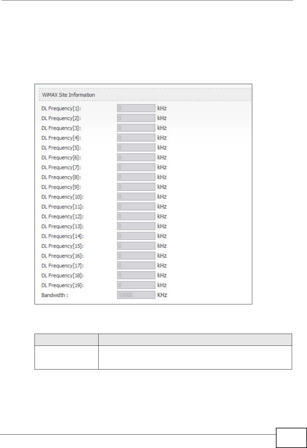
19.2.2 WiMAX Site Information
Click Status > WiMAX Site Information to open this screen. This read-only
screen shows WiMAX frequency information for the WiMAX Modem. These settings
can be configured in the ADVANCED > WAN Configuration > WiMAX
Configuration screen.
Figure 92 WiMAX Site Information
The following table describes the labels in this screen.
Table 98 WiMAX Site Information
LABEL DESCRIPTION
DL Frequency
[1] ~ [19]
These fields show the downlink frequency settings in kilohertz
(kHz). These settings determine how the WiMAX Modem searches
for an available wireless connection.
Chapter 19 The Status Screen
User’s Guide
222
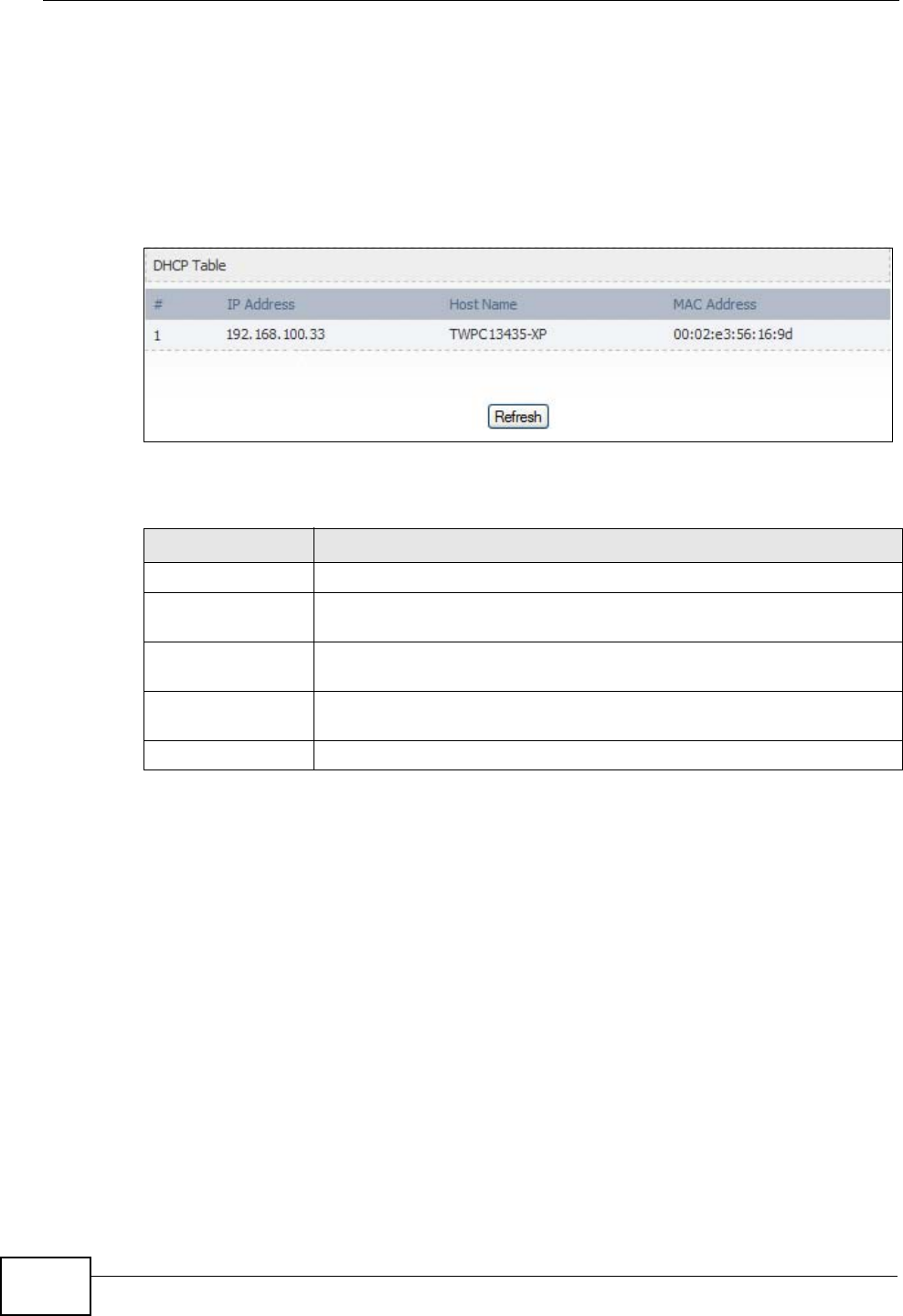
19.2.3 DHCP Table
Click Status > DHCP Table to open this screen. This read-only screen shows the
IP addresses, Host Names and MAC addresses of the devices currently connected
to the WiMAX Modem. These settings can be configured in the ADVANCED > LAN
Configuration > DHCP Setup screen.
Figure 93 DHCP Table
Each field is described in the following table.
Table 99 DHCP Table
LABEL DESCRIPTION
# The number of the item in this list.
IP Address This field displays the IP address the WiMAX Modem assigned to a
computer in the network.
Host Name This field displays the system name of the computer to which the
WiMAX Modem assigned the IP address.
MAC Address This field displays the MAC address of the computer to which the
WiMAX Modem assigned the IP address.
Refresh Click this button to update the table data.
Chapter 19 The Status Screen
User’s Guide 223
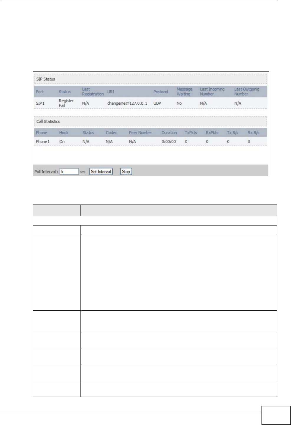
19.2.4 VoIP Statistics
Click Status > DHCP Table to open this screen. This read-only screen shows SIP
registration information, status of calls and VoIP traffic statistics. These settings
can be configured in the VOICE > Service Configuration > SIP Setting screen.
Figure 94 VoIP Statistics
Each field is described in the following table.
Table 100 VoIP Statistics
LABEL DESCRIPTION
SIP Status
Port This column displays each SIP account in the WiMAX Modem.
Status This field displays the current registration status of the SIP account.
You can change this in the Status screen.
Registered - The SIP account is registered with a SIP server.
Register Fail - The last time the WiMAX Modem tried to register the
SIP account with the SIP server, the attempt failed. The WiMAX Modem
automatically tries to register the SIP account when you turn on the
WiMAX Modem or when you activate it.
Inactive - The SIP account is not active. You can activate it in VOICE
> SIP > SIP Settings.
Last
Registration This field displays the last time you successfully registered the SIP
account. It displays N/A if you never successfully registered this
account.
URI This field displays the account number and service domain of the SIP
account. You can change these in VOICE > SIP > SIP Settings.
Protocol This field displays the transport protocol the SIP account uses. SIP
accounts always use UDP.
Message
Waiting This field indicates whether or not there are any messages waiting for
the SIP account.
Last Incoming
Number This field displays the last number that called the SIP account. It
displays N/A if no number has ever dialed the SIP account.
Chapter 19 The Status Screen
User’s Guide
224
Last Outgoing
Number This field displays the last number the SIP account called. It displays
N/A if the SIP account has never dialed a number.
Call Statistics
Phone This field displays the WiMAX Modem’s phone port number.
Hook This field indicates whether the phone is on the hook or off the hook.
On - The phone is hanging up or already hung up.
Off - The phone is dialing, calling, or connected.
Status This field displays the current state of the phone call.
N/A - There are no current VoIP calls, incoming calls or outgoing calls
being made.
DIAL - The callee’s phone is ringing.
RING - The phone is ringing for an incoming VoIP call.
Process - There is a VoIP call in progress.
DISC - The callee’s line is busy, the callee hung up or your phone was
left off the hook.
Codec This field displays what voice codec is being used for a current VoIP call
through a phone port.
Peer Number This field displays the SIP number of the party that is currently engaged
in a VoIP call through a phone port.
Duration This field displays how long the current call has lasted.
Tx Pkts This field displays the number of packets the WiMAX Modem has
transmitted in the current call.
Rx Pkts This field displays the number of packets the WiMAX Modem has
received in the current call.
Tx B/s This field displays how quickly the WiMAX Modem has transmitted
packets in the current call. The rate is the average number of bytes
transmitted per second.
Rx B/s This field displays how quickly the WiMAX Modem has received packets
in the current call. The rate is the average number of bytes transmitted
per second.
Poll Interval(s) Enter how often you want the WiMAX Modem to update this screen, and
click Set Interval.
Set Interval Click this to make the WiMAX Modem update the screen based on the
amount of time you specified in Poll Interval.
Stop Click this to make the WiMAX Modem stop updating the screen.
Table 100 VoIP Statistics
LABEL DESCRIPTION
Chapter 19 The Status Screen
User’s Guide 225
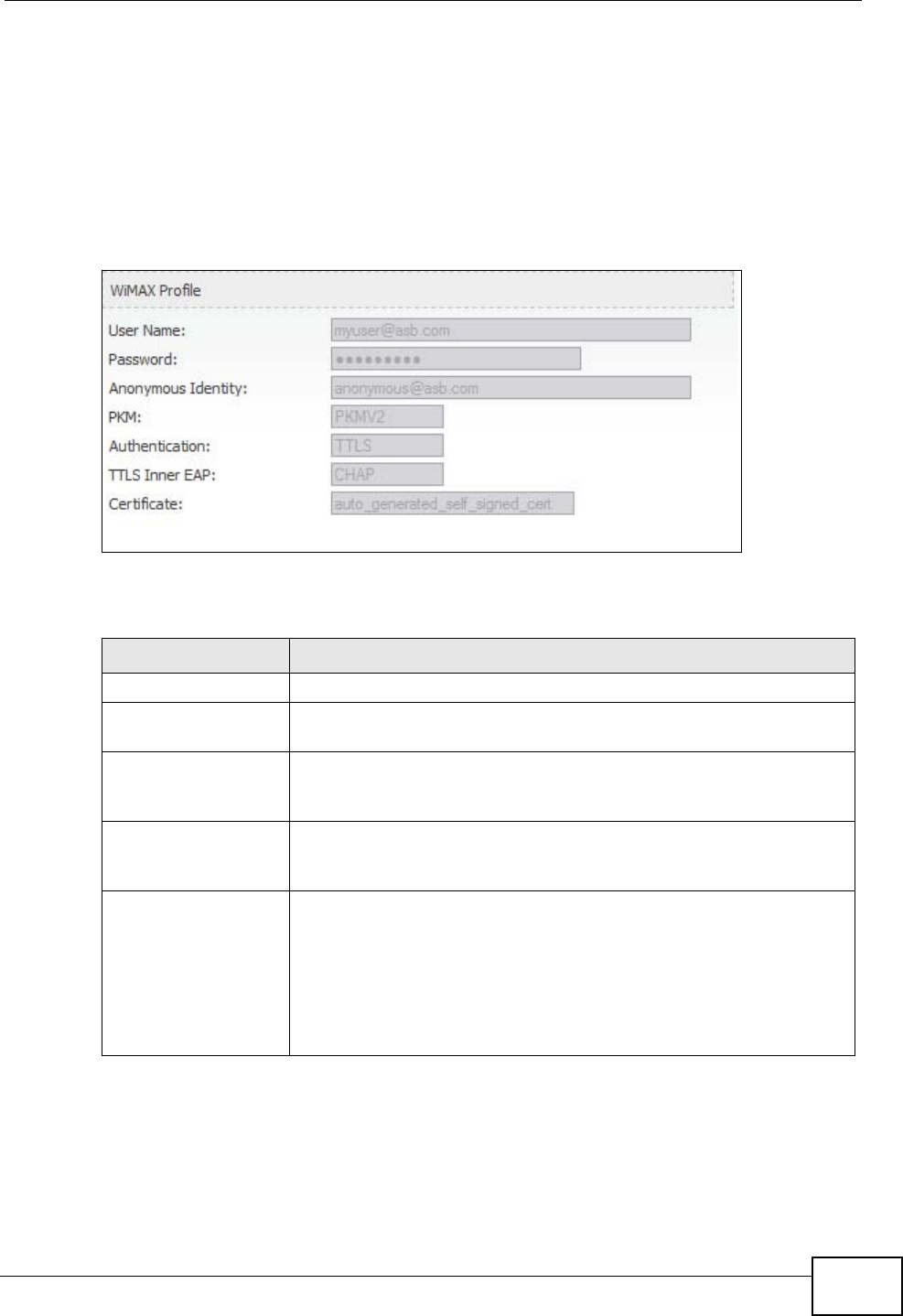
19.2.5 WiMAX Profile
Click Status > WiMAX Profile to open this screen. This read-only screen displays
information about the security settings you are using. To configure these settings,
go to the ADVANCED > WAN Configuration > Internet Connection screen.
Note: Not all WiMAX Modem models have all the fields shown here.
Figure 95 WiMAX Profile
The following table describes the labels in this screen.
Table 101 The WiMAX Profile Screen
LABEL DESCRIPTION
User Name This is the username for your Internet access account.
Password This is the password for your Internet access account. The
password displays as a row of asterisks for security purposes.
Anonymous Identity This is the anonymous identity provided by your Internet Service
Provider. Anonymous identity (also known as outer identity) is
used with EAP-TTLS encryption.
PKM This field displays the Privacy Key Management version number.
PKM provides security between the WiMAX Modem and the base
station. See the WiMAX security appendix for more information.
Authentication This field displays the user authentication method. Authentication
is the process of confirming the identity of a user (by means of a
username and password, for example).
EAP-TTLS allows an MS/SS and a base station to establish a
secure link (or ‘tunnel’) with an AAA (Authentication, Authorization
and Accounting) server in order to exchange authentication
information. See the WiMAX security appendix for more details.

Chapter 19 The Status Screen
User’s Guide
226
TTLS Inner EAP This field displays the type of secondary authentication method.
Once a secure EAP-TTLS connection is established, the inner EAP
is the protocol used to exchange security information between the
mobile station, the base station and the AAA server to
authenticate the mobile station. See the WiMAX security appendix
for more details.
The WiMAX Modem supports the following inner authentication
types:
•CHAP (Challenge Handshake Authentication Protocol)
•MSCHAP (Microsoft CHAP)
•MSCHAPV2 (Microsoft CHAP version 2)
•PAP (Password Authentication Protocol)
Certificate This is the security certificate the WiMAX Modem uses to
authenticate the AAA server, if one is available.
Table 101 The WiMAX Profile Screen (continued)
LABEL DESCRIPTION

227
PART VI
Troubleshooting
and Specifications
Troubleshooting (229)
Product Specifications (237)

228

User’s Guide 229
CHAPTER 20
Troubleshooting
This chapter offers some suggestions to solve problems you might encounter. The
potential problems are divided into the following categories:
•Power, Hardware Connections, and LEDs
•WiMAX Modem Access and Login
•Internet Access
•Phone Calls and VoIP
•Reset the WiMAX Modem to Its Factory Defaults
20.1 Power, Hardware Connections, and LEDs
The WiMAX Modem does not turn on. None of the LEDs turn on.
1Make sure you are using the power adapter or cord included with the WiMAX
Modem.
2Make sure the power adapter or cord is connected to the WiMAX Modem and
plugged in to an appropriate power source. Make sure the power source is turned
on.
3Disconnect and re-connect the power adapter or cord to the WiMAX Modem.
4If the problem continues, contact the vendor.
One of the LEDs does not behave as expected.
1Make sure you understand the normal behavior of the LED. See Section 1.2.1 on
page 34 for more information.

Chapter 20 Troubleshooting
User’s Guide
230
2Check the hardware connections. See the Quick Start Guide.
3Inspect your cables for damage. Contact the vendor to replace any damaged
cables.
4Disconnect and re-connect the power adapter to the WiMAX Modem.
5If the problem continues, contact the vendor.
20.2 WiMAX Modem Access and Login
I forgot the IP address for the WiMAX Modem.
1The default IP address is http://192.168.1.1.
2If you changed the IP address and have forgotten it, you might get the IP address
of the WiMAX Modem by looking up the IP address of the default gateway for your
computer. To do this in most Windows computers, click Start > Run, enter cmd,
and then enter ipconfig. The IP address of the Default Gateway might be the IP
address of the WiMAX Modem (it depends on the network), so enter this IP
address in your Internet browser.
3If this does not work, you have to reset the WiMAX Modem to its factory defaults.
See Section 20.1 on page 229.
I forgot the password.
1The default password is 1234.
2If this does not work, you have to reset the WiMAX Modem to its factory defaults.
See Section 9.5 on page 106.
I cannot see or access the Login screen in the web configurator.
1Make sure you are using the correct IP address.
• The default IP address is http://192.168.1.1.

Chapter 20 Troubleshooting
User’s Guide 231
• If you changed the IP address (Section 5.2 on page 58), use the new IP
address.
• If you changed the IP address and have forgotten it, see the troubleshooting
suggestions for I forgot the IP address for the WiMAX Modem.
2Check the hardware connections, and make sure the LEDs are behaving as
expected. See the Quick Start Guide and Section 1.2.1 on page 34.
3Make sure your Internet browser does not block pop-up windows and has
JavaScript and Java enabled. See Appendix C on page 289.
4If there is a DHCP server on your network, make sure your computer is using a
dynamic IP address. Your WiMAX Modem is a DHCP server by default.
If there is no DHCP server on your network, make sure your computer’s IP
address is in the same subnet as the WiMAX Modem. See Appendix D on page
299.
5Reset the WiMAX Modem to its factory defaults, and try to access the WiMAX
Modem with the default IP address. See Section 9.6 on page 107.
6If the problem continues, contact the network administrator or vendor, or try one
of the advanced suggestions.
Advanced Suggestions
• Try to access the WiMAX Modem using another service, such as Telnet. If you
can access the WiMAX Modem, check the remote management settings and
firewall rules to find out why the WiMAX Modem does not respond to HTTP.
• If your computer is connected wirelessly, use a computer that is connected to a
LAN/ETHERNET port.
I can see the Login screen, but I cannot log in to the WiMAX Modem.
1Make sure you have entered the user name and password correctly. The default
user name is admin, and the default password is 1234. These fields are case-
sensitive, so make sure [Caps Lock] is not on.
2You cannot log in to the web configurator while someone is using Telnet to access
the WiMAX Modem. Log out of the WiMAX Modem in the other session, or ask the
person who is logged in to log out.
3Disconnect and re-connect the power adapter or cord to the WiMAX Modem.
4If this does not work, you have to reset the WiMAX Modem to its factory defaults.
See Section 9.5 on page 106.

Chapter 20 Troubleshooting
User’s Guide
232
I cannot Telnet to the WiMAX Modem.
See the troubleshooting suggestions for I cannot see or access the Login screen in
the web configurator. Ignore the suggestions about your browser.
20.3 Internet Access
I cannot access the Internet.
1Check the hardware connections, and make sure the LEDs are behaving as
expected. See the Quick Start Guide and Section 1.2.1 on page 34.
2Make sure you entered your ISP account information correctly in the wizard.
These fields are case-sensitive, so make sure [Caps Lock] is not on.
3Check your security settings. In the web configurator, go to the Status screen.
Click the WiMAX Profile link in the Summary box and make sure that you are
using the correct security settings for your Internet account.
4Check your WiMAX settings. The WiMAX Modem may have been set to search the
wrong frequencies for a wireless connection. In the web configurator, go to the
Status screen. Click the WiMAX Site Information link in the Summary box and
ensure that the values are correct. If the values are incorrect, enter the correct
frequency settings in the ADVANCED > WAN Configuration > WiMAX
Configuration screen. If you are unsure of the correct values, contact your
service provider.
5If you are trying to access the Internet wirelessly, make sure the wireless settings
in the wireless client are the same as the settings in the AP.
6Disconnect all the cables from your WiMAX Modem, and follow the directions in the
Quick Start Guide again.
7If the problem continues, contact your ISP.
I cannot access the Internet any more. I had access to the Internet (with the
WiMAX Modem), but my Internet connection is not available any more.

Chapter 20 Troubleshooting
User’s Guide 233
1Check the hardware connections, and make sure the LEDs are behaving as
expected. See the Quick Start Guide and Section 1.2.1 on page 34.
2Disconnect and re-connect the power adapter to the WiMAX Modem.
3If the problem continues, contact your ISP.
The Internet connection is slow or intermittent.
1The quality of the WiMAX Modem’s wireless connection to the base station may be
poor. Poor signal reception may be improved by moving the WiMAX Modem away
from thick walls and other obstructions, or to a higher floor in your building.
2There may be radio interference caused by nearby electrical devices such as
microwave ovens and radio transmitters. Move the WiMAX Modem away or switch
the other devices off. Weather conditions may also affect signal quality.
3There might be a lot of traffic on the network. Look at the LEDs, and check Section
1.2.1 on page 34. If the WiMAX Modem is sending or receiving a lot of
information, try closing some programs that use the Internet, especially peer-to-
peer applications.
4Disconnect and re-connect the power adapter to the WiMAX Modem.
5If the problem continues, contact the network administrator or vendor, or try one
of the advanced suggestions.
The Internet connection disconnects.
1Check your WiMAX link and signal strength using the WiMAX Link and Strength
Indicator LEDs on the device.
2Contact your ISP if the problem persists.
20.4 Phone Calls and VoIP
The telephone port won’t work or the telephone lacks a dial tone.

Chapter 20 Troubleshooting
User’s Guide
234
1Check the telephone connections and telephone wire.
2Make sure you have the VOICE > Service Configuration > SIP Settings
screen properly configured (Chapter 10 on page 111).
I can access the Internet, but cannot make VoIP calls.
1Make sure you have the VOICE > Service Configuration > SIP Settings
screen properly configured (Chapter 10 on page 111).
2The VoIP LED should come on. Make sure that your telephone is connected to the
VoIP port (see the Quick Start Guide for information on connecting telephone
cables to the these ports).
3You can also check the VoIP status in the Status screen.
4If the VoIP settings are correct, use speed dial to make peer-to-peer calls. If you
cannot make a call using speed dial, there may be something wrong with the SIP
server. Contact your VoIP service provider.
Problems With Multiple SIP Accounts
You can set up two SIP accounts on your WiMAX Modem. By default your WiMAX
Modem uses SIP account 1 for outgoing calls, and it uses SIP accounts 1 and 2 for
incoming calls. With this setting, you always use SIP account 1 for your outgoing
calls and you cannot distinguish which SIP account the calls are coming in
through. If you want to control the use of different dialing plans for accounting
purposes or other reasons, you need to configure your phone port in order to
control which SIP account you are using when placing or receiving calls.
20.5 Reset the WiMAX Modem to Its Factory
Defaults
If you reset the WiMAX Modem, you lose all of the changes you have made. The
WiMAX Modem re-loads its default settings, and the password resets to 1234. You
have to make all of your changes again.

Chapter 20 Troubleshooting
User’s Guide 235
You will lose all of your changes when you push the Reset button.
To reset the WiMAX Modem,
1Make sure the Power LED is on and not blinking.
2Press and hold the Reset button for five to ten seconds. Release the Reset button
when the Power LED begins to blink. The default settings have been restored.
If the WiMAX Modem restarts automatically, wait for the WiMAX Modem to finish
restarting, and log in to the web configurator. The password is “1234”.
If the WiMAX Modem does not restart automatically, disconnect and reconnect the
WiMAX Modem’s power. Then, follow the directions above again.
20.5.1 Pop-up Windows, JavaScripts and Java Permissions
Please see Appendix C on page 289.

Chapter 20 Troubleshooting
User’s Guide
236

User’s Guide 237
CHAPTER 21
Product Specifications
This chapter gives details about your WiMAX Modem’s hardware and firmware
features.
Table 102 Environmental and Hardware Specifications
FEATURE DESCRIPTION
Operating Temperature 0°C to 45°C
Storage Temperature -25°C to 55°C
Operating Humidity 10% ~ 90% (non-condensing)
Storage Humidity 10% to 95% (non-condensing)
Power Supply 12V DC, 2A
Power Consumption 18W
Ethernet Interface One auto-negotiating, auto-MDI/MDI-X NWay 10/100 Mbps
RJ-45 Ethernet port
Telephony Interface One analog ATA interfaces for standard telephones through
RJ-11 FXS (Foreign Exchange Subscriber) analog connector
Antennas Two internal omnidirectional 7dBi WiMAX antenna for MAX-
216M1R.
Two (optional) SMA external antenna connectors for MAX-
216M1R plus.
Two internal omnidirectional 6dBi WiMAX antenna for MAX-
206M1R & MAx-236M1R.
Weight 400g
Dimensions 260mm (H) x 165mm (W) x 25mm (D)
Safety Approvals UL 60950-1
CAN/CSA C22.2 No. 60950-1-03
EN 60950-1
IEC 60950-1
EMI Approvals EN 301489-1 v1.6.1
EN 61000-3-2
EN 61000-3-3
Chapter 21 Product Specifications
User’s Guide
238
EMS Approvals EN 301489-4 v1.3.1
RF Approvals EN 302326
Table 103 Radio Specifications
FEATURE DESCRIPTION
Media Access Protocol IEEE 802.16e
WiMAX Bandwidth MAX-216M1R: 5MHz, 7MHz, 10MHz
MAX-206M1R: 5MHz, 10MHz
MAX-236M1R: 5MHz, 8.75MHz, 10MHz
Data Rate Download:
Maximum 15 Mbps
Average 6 Mbps
Upload:
Maximum 5 Mbps
Modulation QPSK (uplink and downlink)
16-QAM (uplink and downlink)
64-QAM (downlink only)
Output Power Typically 27dBm with internal antenna
Duplex mode Time Division Duplex (TDD)
Security PKMv2
EAP
CCMP, 128-bit AES
Table 104 Firmware Specifications
FEATURE DESCRIPTION
Web-based Configuration
and Management Tool Also known as “the web configurator”, this is a firmware-
based management solution for the WiMAX Modem. You must
connect using a compatible web browser in order to use it.
High Speed Wireless
Internet Access The WiMAX Modem is ideal for high-speed wireless Internet
browsing.
WiMAX (Worldwide Interoperability for Microwave Access) is
a wireless networking standard providing high-bandwidth,
wide-range secured wireless service. The WiMAX Modem is a
WiMAX mobile station (MS) compatible with the IEEE 802.16e
standard.
Firewall The WiMAX Modem is a stateful inspection firewall with DoS
(Denial of Service) protection. By default, when the firewall is
activated, all incoming traffic from the WAN to the LAN is
blocked unless it is initiated from the LAN. The WiMAX
Modem’s firewall supports TCP/UDP inspection, DoS detection
and prevention, real time alerts, reports and logs.
Table 102 Environmental and Hardware Specifications (continued)

Chapter 21 Product Specifications
User’s Guide 239
Content Filtering The WiMAX Modem can block access to web sites containing
specified keywords. You can define time periods and days
during which content filtering is enabled and include or
exclude a range of users on the LAN from content filtering.
Network Address
Translation (NAT) Network Address Translation (NAT) allows the translation of
an Internet protocol address used within one network (for
example a private IP address used in a local network) to a
different IP address known within another network (for
example a public IP address used on the Internet).
Universal Plug and Play
(UPnP) Your device and other UPnP enabled devices can use the
standard TCP/IP protocol to dynamically join a network,
obtain an IP address and convey their capabilities to each
other.
Dynamic DNS Support With Dynamic DNS support, you can have a static hostname
alias for a dynamic IP address, allowing the host to be more
easily accessible from various locations on the Internet. You
must register for this service with a Dynamic DNS service
provider.
DHCP DHCP (Dynamic Host Configuration Protocol) allows the
individual clients (computers) to obtain the TCP/IP
configuration at start-up from a centralized DHCP server.
Your device has built-in DHCP server capability enabled by
default. It can assign IP addresses, an IP default gateway
and DNS servers to DHCP clients. Your device can also act as
a surrogate DHCP server (DHCP Relay) where it relays IP
address assignment from the actual real DHCP server to the
clients.
IP Alias IP alias allows you to partition a physical network into logical
networks over the same Ethernet interface. Your device
supports three logical LAN interfaces via its single physical
Ethernet interface with the your device itself as the gateway
for each LAN network.
Multiple SIP Accounts You can configure multiple voice (SIP) accounts.
SIP ALG Your device is a SIP Application Layer Gateway (ALG). It
allows VoIP calls to pass through NAT for devices behind it
(such as a SIP-based VoIP software application on a
computer).
Dynamic Jitter Buffer The built-in adaptive buffer helps to smooth out the
variations in delay (jitter) for voice traffic (up to 60 ms). This
helps ensure good voice quality for your conversations.
Voice Activity Detection/
Silence Suppression Voice Activity Detection (VAD) reduces the bandwidth that a
call uses by not transmitting when you are not speaking.
Comfort Noise Generation Your device generates background noise to fill moments of
silence when the other device in a call stops transmitting
because the other party is not speaking (as total silence
could easily be mistaken for a lost connection).
Echo Cancellation You device supports G.168 of at least 24 ms.
This an ITU-T standard for eliminating the echo caused by the
sound of your voice reverberating in the telephone receiver
while you talk.
Table 104 Firmware Specifications (continued)
FEATURE DESCRIPTION
Chapter 21 Product Specifications
User’s Guide
240
Time and Date Get the current time and date from an external server when
you turn on your WiMAX Modem. You can also set the time
manually.
Logging Use the WiMAX Modem’s logging feature to view connection
history, surveillance logs, and error messages.
Codecs Enhanced Variable Rate Codec (EVRC), G.711 (PCM µ-law
and a-law), G.729a, and G.723.1
Fax Support T.38 FAX relay (FAX over UDP).
G.711 fax relay for fax calls and be able to renegotiate codec
to G.711 if a fax call is detected.
Ring Tones Supports different distinctive ring tones on each line.
Call Prioritization Prioritize VoIP traffic originating from the RJ-11 ports over
any other traffic.
Table 105 Standards Supported
STANDARD DESCRIPTION
RFC 768 User Datagram Protocol
RFC 791 Internet Protocol v4
RFC 792 Internet Control Message Protocol
RFC 792 Transmission Control Protocol
RFC 826 Address Resolution Protocol
RFC 854 Telnet Protocol
RFC 1349 Type of Service Protocol
RFC 1706 DNS NSAP Resource Records
RFC 1889 Real-time Transport Protocol (RTP)
RFC 1890 Real-time Transport Control Protocol (RTCP)
RFC 2030 Simple Network Time Protocol
RFC 2104 HMAC: Keyed-Hashing for Message Authentication
RFC 2131 Dynamic Host Configuration Protocol
RFC 2401 Security Architecture for the Internet Protocol
RFC 2409 Internet Key Exchange
RFC 2475 Architecture for Differentiated Services (Diffserv)
RFC 2617 Hypertext Transfer Protocol (HTTP) Authentication: Basic and
Digest Access Authentication
RFC 2782 A DNS RR for specifying the location of services (DNS SRV)
RFC 2833 Real-time Transport Protocol Payload for DTMF Digits,
Telephony Tones and Telephony Signals
RFC 2976 The SIP INFO Method
RFC 3261 Session Initiation Protocol (SIP version 2)
RFC 3262 Reliability of Provisional Responses in the Session Initiation
Protocol (SIP).
Table 104 Firmware Specifications (continued)
FEATURE DESCRIPTION
Chapter 21 Product Specifications
User’s Guide 241
RFC 3263 Session Initiation Protocol (SIP): Locating SIP Servers
RFC 3264 An Offer/Answer Model with the Session Description Protocol
(SDP)
RFC 3265 Session Initiation Protocol (SIP)-Specific Event Notification
RFC 3323 A Privacy Mechanism for SIP
RFC 3325 Private Extensions to the Session Initiation Protocol (SIP) for
Asserted Identity within Trusted Networks
RFC 3550 RTP - A Real Time Protocol for Real-Time Applications
RFC 3581 An Extension to the Session Initiation Protocol (SIP) for
Symmetric Response Routing
RFC 3611 RTP Control Protocol Extended Reports (RTCP XR)-XR
RFC 3715 IP Sec/NAT Compatibility
RFC 3842 A Message Summary and Message Waiting Indication Event
Package for the Session Initiation Protocol (SIP)
IEEE 802.3 10BASE5 10 Mbit/s (1.25 MB/s)
IEEE 802.3u 100BASE-TX, 100BASE-T4, 100BASE-FX Fast Ethernet at 100
Mbit/s (12.5 MB/s) with auto-negotiation
Table 106 Voice Features
Call Park and
Pickup Call park and pickup lets you put a call on hold (park) and then
continue the call (pickup). The caller must still pay while the call is
parked.
When you park the call, you enter a number of your choice (up to
eight digits), which you must enter again when you pick up the call. If
you do not enter the correct number, you cannot pickup the call. This
means that only someone who knows the number you have chosen
can pick up the call.
You can have more than one call on hold at the same time, but you
must give each call a different number.
Call Return With call return, you can place a call to the last number that called
you (either answered or missed). The last incoming call can be
through either SIP or PSTN.
Country Code Phone standards and settings differ from one country to another, so
the settings on your WiMAX Modem must be configured to match
those of the country you are in. The country code feature allows you
to do this by selecting the country from a list rather than changing
each setting manually. Configure the country code feature when you
move the WiMAX Modem from one country to another.
Do not Disturb
(DnD) This feature allows you to set your phone not to ring when someone
calls you. You can set each phone independently using its keypad, or
configure global settings for all phones using the command line
interpreter.
Auto Dial You can set the WiMAX Modem to automatically dial a specified
number immediately whenever you lift a phone off the hook. Use the
Web Configurator to set the specified number. Use the command line
interpreter to have the WiMAX Modem wait a specified length of time
before dialing the number.
Table 105 Standards Supported (continued)
STANDARD DESCRIPTION

Chapter 21 Product Specifications
User’s Guide
242
Phone config The phone configuration table allows you to customize the phone
keypad combinations you use to access certain features on the
WiMAX Modem, such as call waiting, call return, call forward, etc. The
phone configuration table is configurable in command interpreter
mode.
Firmware update
enable / disable If your service provider uses this feature, you hear a recorded
message when you pick up the phone when new firmware is available
for your WiMAX Modem. Enter *99# in your phone’s keypad to have
the WiMAX Modem upgrade the firmware, or enter #99# to not
upgrade. If your service provider gave you different numbers to use,
enter them instead. If you enter the code to not upgrade, you can
make a call as normal. You will hear the recording again each time
you pick up the phone, until you upgrade.
Call waiting This feature allows you to hear an alert when you are already using
the phone and another person calls you. You can then either reject
the new incoming call, put your current call on hold and receive the
new incoming call, or end the current call and receive the new
incoming call.
Call forwarding With this feature, you can set the WiMAX Modem to forward calls to a
specified number, either unconditionally (always), when your number
is busy, or when you do not answer. You can also forward incoming
calls from one specified number to another.
Caller ID The WiMAX Modem supports caller ID, which allows you to see the
originating number of an incoming call (on a phone with a suitable
display).
REN A Ringer Equivalence Number (REN) is used to determine the number
of devices (like telephones or fax machines) that may be connected
to the telephone line. Your device has a REN of three, so it can
support three devices per telephone port.
QoS (Quality of
Service) Quality of Service (QoS) mechanisms help to provide better service
on a per-flow basis. Your device supports Type of Service (ToS)
tagging and Differentiated Services (DiffServ) tagging. This allows
the device to tag voice frames so they can be prioritized over the
network.
Table 106 Voice Features
Chapter 21 Product Specifications
User’s Guide 243
SIP ALG Your device is a SIP Application Layer Gateway (ALG). It allows VoIP
calls to pass through NAT for devices behind it (such as a SIP-based
VoIP software application on a computer).
Other Voice
Features SIP version 2 (Session Initiating Protocol RFC 3261)
SDP (Session Description Protocol RFC 2327)
RTP (RFC 1889)
RTCP (RFC 1890)
Voice codecs (coder/decoders) G.711, G.726, G.729
Fax and data modem discrimination
DTMF Detection and Generation
DTMF: In-band and Out-band traffic (RFC 2833),(PCM), (SIP INFO)
Point-to-point call establishment between two IADs
Quick dialing through predefined phone book, which maps the phone
dialing number and destination URL.
Flexible Dial Plan (RFC3525 section 7.1.14)
Table 107 Star (*) and Pound (#) Code Support
*0 Wireless Operator Services
*2 Customer Care Access
*66 Repeat Dialing
*67 Plus the 10 digit phone number to block Caller ID on a single call
basis
*69 Return last call received
*70 Followed by the 10 digit phone number to cancel Call Waiting on a
single call basis
*72 Activate Call Forwarding (*72 followed by the 10 digit phone number
that is requesting call forwarding service)
*720 Activate Call Forwarding (*720 followed by the 10 digit phone
number that is requesting deactivation of call forwarding service)
*73 Plus the forward to phone number to activate Call Forwarding No
Answer (no VM service plan)
*730 Deactivate Call Forwarding No Answer
*740 Plus the forward to phone number to activate Call Forwarding Busy
(no VM service plan)
*911/911 Emergency phone number (same as dialing 911)
*411/411 Wireless Information Services
Table 108 Environmental and Hardware Specifications
FEATURE DESCRIPTION
Operating Temperature 0°C to 45°C
Storage Temperature -25°C to 55°C
Table 106 Voice Features
Chapter 21 Product Specifications
User’s Guide
244
Operating Humidity 20% ~ 90% (non-condensing)
Storage Humidity 10% to 95% (non-condensing)
Power Supply 12V DC, 2 A
Power consumption 18W
Ethernet Interface Two auto-negotiating, auto-MDI/MDI-X NWay 10/100 Mbps
RJ-45 Ethernet ports
Telephony Interface Two analog ATA interfaces for standard telephones through
RJ-11 FXS (Foreign Exchange Subscriber) analog connector
Antennas Two internal 5dBi WiMAX antennas
Weight 480g
Dimensions 160mm (W) x 118mm (D) x 167mm (H)
Safety Approvals UL 60950-1
CAN/CSA C22.2 No. 60950-1-03
EN 60950-1
IEC 60950-1
EMI Approvals EN 301489-1 v1.6.1
EN 61000-3-2
EN 61000-3-3
EMS Approvals EN 301489-4 v1.3.1
RF Approvals EN 302326
Table 109 Radio Specifications
FEATURE DESCRIPTION
Media Access Protocol IEEE 802.16e
WiMAX Bandwidth 2.5 GHz
Data Rate Download:
Maximum 20 Mbps
Average 6 Mbps
Upload:
Maximum 4 Mbps
Average 3 Mbps
Modulation QPSK (uplink and downlink)
16-QAM (uplink and downlink)
64-QAM (downlink only)
Output Power 27dBm with external antennas attached
Duplex mode Time Division Duplex (TDD)
Security PKMv2
EAP
CCMP, 128-bit AES
Table 108 Environmental and Hardware Specifications (continued)

Chapter 21 Product Specifications
User’s Guide 245
Table 110 Firmware Specifications
FEATURE DESCRIPTION
Web-based Configuration
and Management Tool Also known as “the web configurator”, this is a firmware-
based management solution for the WiMAX Modem. You must
connect using a compatible web browser in order to use it.
High Speed Wireless
Internet Access The WiMAX Modem is ideal for high-speed wireless Internet
browsing.
WiMAX (Worldwide Interoperability for Microwave Access) is
a wireless networking standard providing high-bandwidth,
wide-range secured wireless service. The WiMAX Modem is a
WiMAX mobile station (MS) compatible with the IEEE 802.16e
standard.
Firewall The WiMAX Modem is a stateful inspection firewall with DoS
(Denial of Service) protection. By default, when the firewall is
activated, all incoming traffic from the WAN to the LAN is
blocked unless it is initiated from the LAN. The WiMAX
Modem’s firewall supports TCP/UDP inspection, DoS detection
and prevention, real time alerts, reports and logs.
Content Filtering The WiMAX Modem can block access to web sites containing
specified keywords. You can define time periods and days
during which content filtering is enabled and include or
exclude a range of users on the LAN from content filtering.
Network Address
Translation (NAT) Network Address Translation (NAT) allows the translation of
an Internet protocol address used within one network (for
example a private IP address used in a local network) to a
different IP address known within another network (for
example a public IP address used on the Internet).
Universal Plug and Play
(UPnP) Your device and other UPnP enabled devices can use the
standard TCP/IP protocol to dynamically join a network,
obtain an IP address and convey their capabilities to each
other.
Dynamic DNS Support With Dynamic DNS support, you can have a static hostname
alias for a dynamic IP address, allowing the host to be more
easily accessible from various locations on the Internet. You
must register for this service with a Dynamic DNS service
provider.
DHCP DHCP (Dynamic Host Configuration Protocol) allows the
individual clients (computers) to obtain the TCP/IP
configuration at start-up from a centralized DHCP server.
Your device has built-in DHCP server capability enabled by
default. It can assign IP addresses, an IP default gateway
and DNS servers to DHCP clients. Your device can also act as
a surrogate DHCP server (DHCP Relay) where it relays IP
address assignment from the actual real DHCP server to the
clients.
IP Alias IP alias allows you to partition a physical network into logical
networks over the same Ethernet interface. Your device
supports three logical LAN interfaces via its single physical
Ethernet interface with the your device itself as the gateway
for each LAN network.
Multiple SIP Accounts You can configure multiple voice (SIP) accounts.
Chapter 21 Product Specifications
User’s Guide
246
SIP ALG Your device is a SIP Application Layer Gateway (ALG). It
allows VoIP calls to pass through NAT for devices behind it
(such as a SIP-based VoIP software application on a
computer).
Dynamic Jitter Buffer The built-in adaptive buffer helps to smooth out the
variations in delay (jitter) for voice traffic (up to 60 ms). This
helps ensure good voice quality for your conversations.
Voice Activity Detection/
Silence Suppression Voice Activity Detection (VAD) reduces the bandwidth that a
call uses by not transmitting when you are not speaking.
Comfort Noise Generation Your device generates background noise to fill moments of
silence when the other device in a call stops transmitting
because the other party is not speaking (as total silence
could easily be mistaken for a lost connection).
Echo Cancellation You device supports G.168 of at least 24 ms.
This an ITU-T standard for eliminating the echo caused by the
sound of your voice reverberating in the telephone receiver
while you talk.
Time and Date Get the current time and date from an external server when
you turn on your WiMAX Modem. You can also set the time
manually.
Logging Use the WiMAX Modem’s logging feature to view connection
history, surveillance logs, and error messages.
Codecs Enhanced Variable Rate Codec (EVRC), G.711 (PCM µ-law
and a-law), G.729a, and G.723.1
Fax Support T.38 FAX relay (FAX over UDP).
G.711 fax relay for fax calls and be able to renegotiate codec
to G.711 if a fax call is detected.
Ring Tones Supports different distinctive ring tones on each line.
Call Prioritization Prioritize VoIP traffic originating from the RJ-11 ports over
any other traffic.
Table 111 Standards Supported
STANDARD DESCRIPTION
RFC 768 User Datagram Protocol
RFC 791 Internet Protocol v4
RFC 792 Internet Control Message Protocol
RFC 792 Transmission Control Protocol
RFC 826 Address Resolution Protocol
RFC 854 Telnet Protocol
RFC 1349 Type of Service Protocol
RFC 1706 DNS NSAP Resource Records
RFC 1889 Real-time Transport Protocol (RTP)
RFC 1890 Real-time Transport Control Protocol (RTCP)
RFC 2030 Simple Network Time Protocol
Table 110 Firmware Specifications (continued)
FEATURE DESCRIPTION

Chapter 21 Product Specifications
User’s Guide 247
RFC 2104 HMAC: Keyed-Hashing for Message Authentication
RFC 2131 Dynamic Host Configuration Protocol
RFC 2401 Security Architecture for the Internet Protocol
RFC 2409 Internet Key Exchange
RFC 2475 Architecture for Differentiated Services (Diffserv)
RFC 2617 Hypertext Transfer Protocol (HTTP) Authentication: Basic and
Digest Access Authentication
RFC 2782 A DNS RR for specifying the location of services (DNS SRV)
RFC 2833 Real-time Transport Protocol Payload for DTMF Digits,
Telephony Tones and Telephony Signals
RFC 2976 The SIP INFO Method
RFC 3261 Session Initiation Protocol (SIP version 2)
RFC 3262 Reliability of Provisional Responses in the Session Initiation
Protocol (SIP).
RFC 3263 Session Initiation Protocol (SIP): Locating SIP Servers
RFC 3264 An Offer/Answer Model with the Session Description Protocol
(SDP)
RFC 3265 Session Initiation Protocol (SIP)-Specific Event Notification
RFC 3323 A Privacy Mechanism for SIP
RFC 3325 Private Extensions to the Session Initiation Protocol (SIP) for
Asserted Identity within Trusted Networks
RFC 3550 RTP - A Real Time Protocol for Real-Time Applications
RFC 3581 An Extension to the Session Initiation Protocol (SIP) for
Symmetric Response Routing
RFC 3611 RTP Control Protocol Extended Reports (RTCP XR)-XR
RFC 3715 IP Sec/NAT Compatibility
RFC 3842 A Message Summary and Message Waiting Indication Event
Package for the Session Initiation Protocol (SIP)
IEEE 802.3 10BASE5 10 Mbit/s (1.25 MB/s)
IEEE 802.3u 100BASE-TX, 100BASE-T4, 100BASE-FX Fast Ethernet at 100
Mbit/s (12.5 MB/s) with auto-negotiation
Table 111 Standards Supported (continued)
STANDARD DESCRIPTION

Chapter 21 Product Specifications
User’s Guide
248
Table 112 Voice Features
Call Park and
Pickup Call park and pickup lets you put a call on hold (park) and then
continue the call (pickup). The caller must still pay while the call is
parked.
When you park the call, you enter a number of your choice (up to
eight digits), which you must enter again when you pick up the call. If
you do not enter the correct number, you cannot pickup the call. This
means that only someone who knows the number you have chosen
can pick up the call.
You can have more than one call on hold at the same time, but you
must give each call a different number.
Call Return With call return, you can place a call to the last number that called
you (either answered or missed). The last incoming call can be
through either SIP or PSTN.
Country Code Phone standards and settings differ from one country to another, so
the settings on your WiMAX Modem must be configured to match
those of the country you are in. The country code feature allows you
to do this by selecting the country from a list rather than changing
each setting manually. Configure the country code feature when you
move the WiMAX Modem from one country to another.
Do not Disturb
(DnD) This feature allows you to set your phone not to ring when someone
calls you. You can set each phone independently using its keypad, or
configure global settings for all phones using the command line
interpreter.
Auto Dial You can set the WiMAX Modem to automatically dial a specified
number immediately whenever you lift a phone off the hook. Use the
Web Configurator to set the specified number. Use the command line
interpreter to have the WiMAX Modem wait a specified length of time
before dialing the number.
Phone config The phone config table allows you to customize the phone keypad
combinations you use to access certain features on the WiMAX
Modem, such as call waiting, call return, call forward, etc. The phone
config table is configurable in command interpreter mode.
Firmware update
enable / disable If your service provider uses this feature, you hear a recorded
message when you pick up the phone when new firmware is available
for your WiMAX Modem. Enter *99# in your phone’s keypad to have
the WiMAX Modem upgrade the firmware, or enter #99# to not
upgrade. If your service provider gave you different numbers to use,
enter them instead. If you enter the code to not upgrade, you can
make a call as normal. You will hear the recording again each time
you pick up the phone, until you upgrade.
Call waiting This feature allows you to hear an alert when you are already using
the phone and another person calls you. You can then either reject
the new incoming call, put your current call on hold and receive the
new incoming call, or end the current call and receive the new
incoming call.
Call forwarding With this feature, you can set the WiMAX Modem to forward calls to a
specified number, either unconditionally (always), when your number
is busy, or when you do not answer. You can also forward incoming
calls from one specified number to another.

Chapter 21 Product Specifications
User’s Guide 249
Caller ID The WiMAX Modem supports caller ID, which allows you to see the
originating number of an incoming call (on a phone with a suitable
display).
REN A Ringer Equivalence Number (REN) is used to determine the number
of devices (like telephones or fax machines) that may be connected
to the telephone line. Your device has a REN of three, so it can
support three devices per telephone port.
QoS (Quality of
Service) Quality of Service (QoS) mechanisms help to provide better service
on a per-flow basis. Your device supports Type of Service (ToS)
tagging and Differentiated Services (DiffServ) tagging. This allows
the device to tag voice frames so they can be prioritized over the
network.
SIP ALG Your device is a SIP Application Layer Gateway (ALG). It allows VoIP
calls to pass through NAT for devices behind it (such as a SIP-based
VoIP software application on a computer).
Other Voice
Features SIP version 2 (Session Initiating Protocol RFC 3261)
SDP (Session Description Protocol RFC 2327)
RTP (RFC 1889)
RTCP (RFC 1890)
Voice codecs (coder/decoders) G.711, G.726, G.729
Fax and data modem discrimination
DTMF Detection and Generation
DTMF: In-band and Out-band traffic (RFC 2833),(PCM), (SIP INFO)
Point-to-point call establishment between two IADs
Quick dialing through predefined phone book, which maps the phone
dialing number and destination URL.
Flexible Dial Plan (RFC3525 section 7.1.14)
Table 113 Star (*) and Pound (#) Code Support
*0 Wireless Operator Services
*2 Customer Care Access
*66 Repeat Dialing
*67 Plus the 10 digit phone number to block Caller ID on a single call
basis
*69 Return last call received
*70 Followed by the 10 digit phone number to cancel Call Waiting on a
single call basis
*72 Activate Call Forwarding (*72 followed by the 10 digit phone number
that is requesting call forwarding service)
*720 Activate Call Forwarding (*720 followed by the 10 digit phone
number that is requesting deactivation of call forwarding service)
*73 Plus the forward to phone number to activate Call Forwarding No
Answer (no VM service plan)
Table 112 Voice Features

Chapter 21 Product Specifications
User’s Guide
250
Note: To take full advantage of the supplementary phone services available through
the WiMAX Modem's phone port, you may need to subscribe to the services
from your voice account service provider.
Not all features are supported by all service providers. Consult your service
provider for more information.
*730 Deactivate Call Forwarding No Answer
*740 Plus the forward to phone number to activate Call Forwarding Busy
(no VM service plan)
*911/911 Emergency phone number (same as dialing 911)
*411/411 Wireless Information Services
Table 113 Star (*) and Pound (#) Code Support
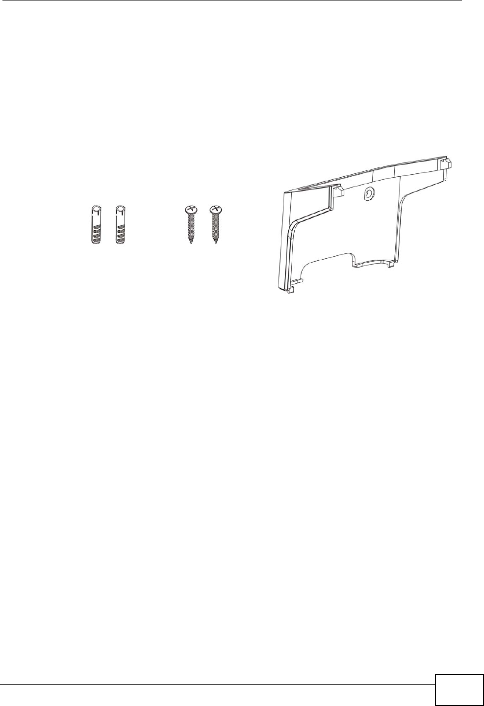
Chapter 21 Product Specifications
User’s Guide 251
21.1 Wall-Mounting
This section shows you how to mount your WiMAX Modem on a wall using the
ZyXEL Wall-Mounting kit (not included).
21.1.1 The Wall-Mounting Kit
The wall-mounting kit contains the following parts:
1Two Mortar Plugs (M4*L30 mm)
2Two Screws (M4*L30 mm)
3Wall-Mounting Chassis
If any parts are missing, contact your vendor.
21.1.2 Instructions
To mount the WiMAX Modem on a wall:
1Select a position free of obstructions on a sturdy wall.
2Drill two holes in the wall exactly 70 mm apart. The holes should be 6 mm wide
and at least 30 mm deep.
Be careful to avoid damaging pipes or cables located inside the
wall when drilling holes for the screws.
12 3
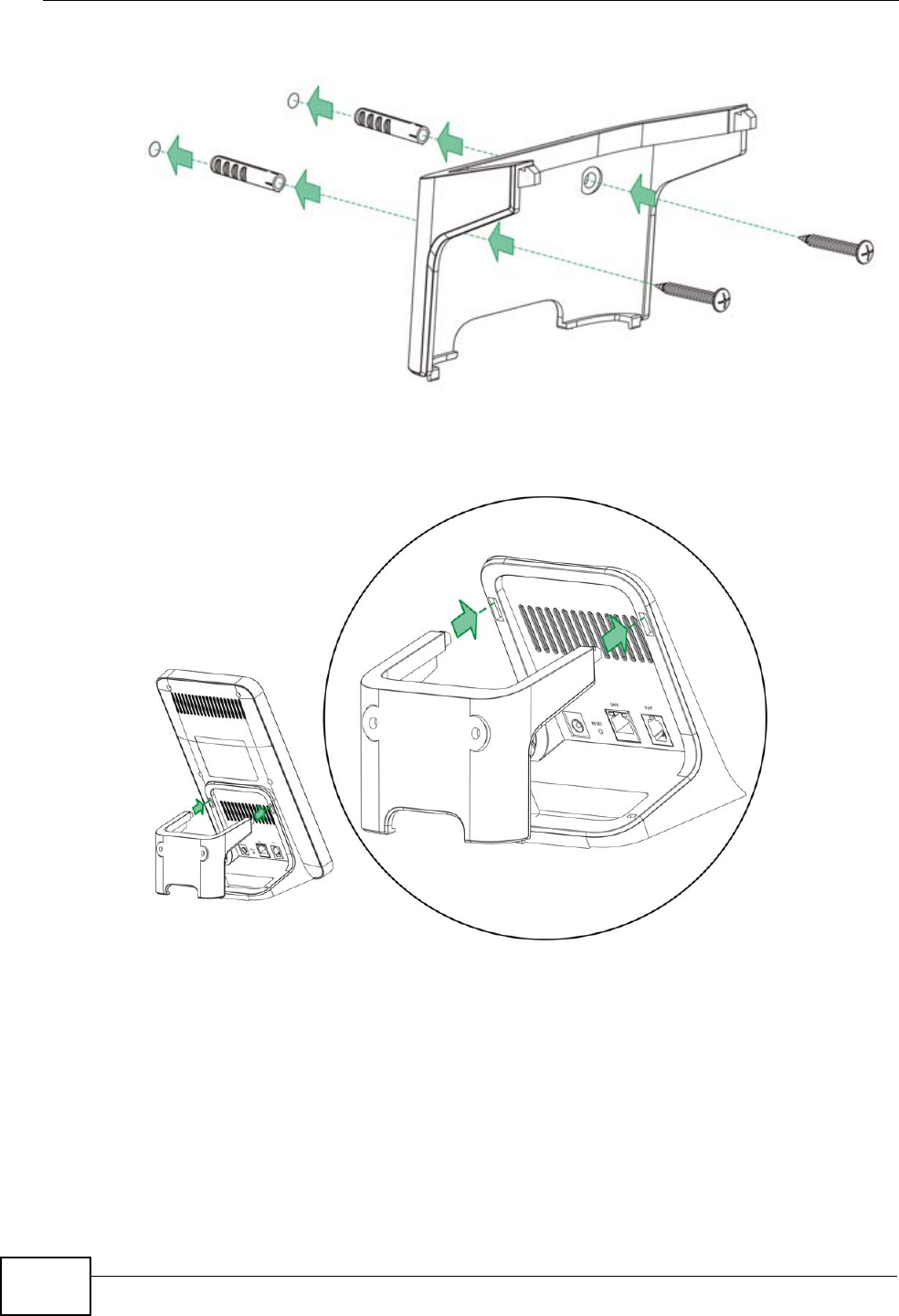
Chapter 21 Product Specifications
User’s Guide
252
3Attach the wall mounting chassis with the plugs and screws as shown below:
4Connect the MAX-216M1 to the wall mounting chassis by snapping the chassis’
two upper chassis hooks into the matching holes on the WiMAX Modem:
Do not pinch or server the cable connections between the wall-
mounting chassis the WiMAX Modem.
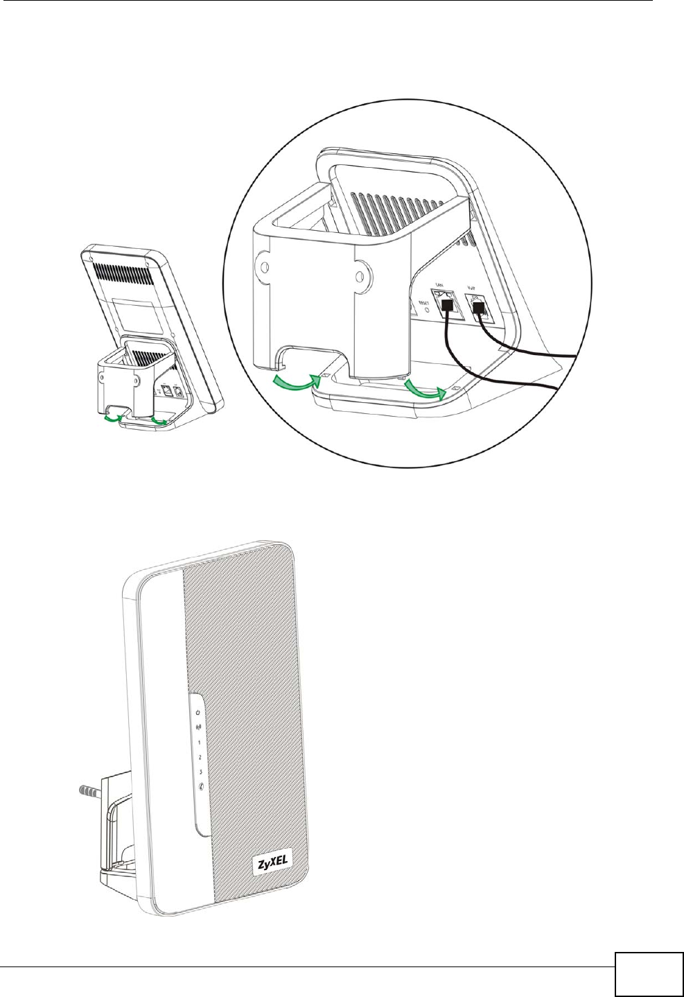
Chapter 21 Product Specifications
User’s Guide 253
5Snap the lower chassis hooks into the matching holes on the WiMAX Modem. The
cable connections should come out either the left or right gaps between the wall-
mounting chassis and the WiMAX Modem
6Once you have snapped the wall-mounting chassis in place, the WiMAX Modem is
securely fastened to the wall.

Chapter 21 Product Specifications
User’s Guide
254

255
PART VII
Appendices and
Index
WiMAX Security (257)
Setting Up Your Computer’s IP Address
(261)
Pop-up Windows, JavaScripts and Java
Permissions (289)
IP Addresses and Subnetting (299)
Importing Certificates (311)
SIP Passthrough (343)
Common Services (345)
Legal Information (349)
Customer Support (353)

256

User’s Guide 257
APPENDIX A
WiMAX Security
Wireless security is vital to protect your wireless communications. Without it,
information transmitted over the wireless network would be accessible to any
networking device within range.
User Authentication and Data Encryption
The WiMAX (IEEE 802.16) standard employs user authentication and encryption to
ensure secured communication at all times.
User authentication is the process of confirming a user’s identity and level of
authorization. Data encryption is the process of encoding information so that it
cannot be read by anyone who does not know the code.
WiMAX uses PKMv2 (Privacy Key Management version 2) for authentication, and
CCMP (Counter Mode with Cipher Block Chaining Message Authentication Protocol)
for data encryption.
WiMAX supports EAP (Extensible Authentication Protocol, RFC 2486) which allows
additional authentication methods to be deployed with no changes to the base
station or the mobile or subscriber stations.
PKMv2
PKMv2 is a procedure that allows authentication of a mobile or subscriber station
and negotiation of a public key to encrypt traffic between the MS/SS and the base
station. PKMv2 uses standard EAP methods such as Transport Layer Security
(EAP-TLS) or Tunneled TLS (EAP-TTLS) for secure communication.
In cryptography, a ‘key’ is a piece of information, typically a string of random
numbers and letters, that can be used to ‘lock’ (encrypt) or ‘unlock’ (decrypt) a
message. Public key encryption uses key pairs, which consist of a public (freely
available) key and a private (secret) key. The public key is used for encryption
and the private key is used for decryption. You can decrypt a message only if you
have the private key. Public key certificates (or ‘digital IDs’) allow users to verify
each other’s identity.

Appendix A WiMAX Security
User’s Guide
258
RADIUS
RADIUS is based on a client-server model that supports authentication,
authorization and accounting. The base station is the client and the server is the
RADIUS server. The RADIUS server handles the following tasks:
• Authentication
Determines the identity of the users.
• Authorization
Determines the network services available to authenticated users once they are
connected to the network.
•Accounting
Keeps track of the client’s network activity.
RADIUS is a simple package exchange in which your base station acts as a
message relay between the MS/SS and the network RADIUS server.
Types of RADIUS Messages
The following types of RADIUS messages are exchanged between the base station
and the RADIUS server for user authentication:
• Access-Request
Sent by an base station requesting authentication.
• Access-Reject
Sent by a RADIUS server rejecting access.
• Access-Accept
Sent by a RADIUS server allowing access.
• Access-Challenge
Sent by a RADIUS server requesting more information in order to allow access.
The base station sends a proper response from the user and then sends another
Access-Request message.
The following types of RADIUS messages are exchanged between the base station
and the RADIUS server for user accounting:
•Accounting-Request
Sent by the base station requesting accounting.
• Accounting-Response
Sent by the RADIUS server to indicate that it has started or stopped accounting.
In order to ensure network security, the access point and the RADIUS server use a
shared secret key, which is a password they both know. The key is not sent over

Appendix A WiMAX Security
User’s Guide 259
the network. In addition to the shared key, password information exchanged is
also encrypted to protect the network from unauthorized access.
Diameter
Diameter (RFC 3588) is a type of AAA server that provides several improvements
over RADIUS in efficiency, security, and support for roaming.
Security Association
The set of information about user authentication and data encryption between two
computers is known as a security association (SA). In a WiMAX network, the
process of security association has three stages.
• Authorization request and reply
The MS/SS presents its public certificate to the base station. The base station
verifies the certificate and sends an authentication key (AK) to the MS/SS.
• Key request and reply
The MS/SS requests a transport encryption key (TEK) which the base station
generates and encrypts using the authentication key.
• Encrypted traffic
The MS/SS decrypts the TEK (using the authentication key). Both stations can
now securely encrypt and decrypt the data flow.
CCMP
All traffic in a WiMAX network is encrypted using CCMP (Counter Mode with Cipher
Block Chaining Message Authentication Protocol). CCMP is based on the 128-bit
Advanced Encryption Standard (AES) algorithm.
‘Counter mode’ refers to the encryption of each block of plain text with an
arbitrary number, known as the counter. This number changes each time a block
of plain text is encrypted. Counter mode avoids the security weakness of repeated
identical blocks of encrypted text that makes encrypted data vulnerable to
pattern-spotting.
‘Cipher Block Chaining Message Authentication’ (also known as CBC-MAC) ensures
message integrity by encrypting each block of plain text in such a way that its
encryption is dependent on the block before it. This series of ‘chained’ blocks
creates a message authentication code (MAC or CMAC) that ensures the encrypted
data has not been tampered with.

Appendix A WiMAX Security
User’s Guide
260
Authentication
The WiMAX Modem supports EAP-TTLS authentication.
EAP-TTLS (Tunneled Transport Layer Service)
EAP-TTLS is an extension of the EAP-TLS authentication that uses certificates for
only the server-side authentications to establish a secure connection (with EAP-
TLS digital certifications are needed by both the server and the wireless clients for
mutual authentication). Client authentication is then done by sending username
and password through the secure connection, thus client identity is protected. For
client authentication, EAP-TTLS supports EAP methods and legacy authentication
methods such as PAP, CHAP, MS-CHAP and MS-CHAP v2.

User’s Guide 261
APPENDIX B
Setting Up Your Computer’s IP
Address
Note: Your specific ZyXEL device may not support all of the operating systems
described in this appendix. See the product specifications for more information
about which operating systems are supported.
This appendix shows you how to configure the IP settings on your computer in
order for it to be able to communicate with the other devices on your network.
Windows Vista/XP/2000, Mac OS 9/OS X, and all versions of UNIX/LINUX include
the software components you need to use TCP/IP on your computer.
If you manually assign IP information instead of using a dynamic IP, make sure
that your network’s computers have IP addresses that place them in the same
subnet.
In this appendix, you can set up an IP address for:
•Windows XP/NT/2000 on page 262
•Windows Vista on page 265
•Mac OS X: 10.3 and 10.4 on page 269
•Mac OS X: 10.5 on page 273
•Linux: Ubuntu 8 (GNOME) on page 276
•Linux: openSUSE 10.3 (KDE) on page 282
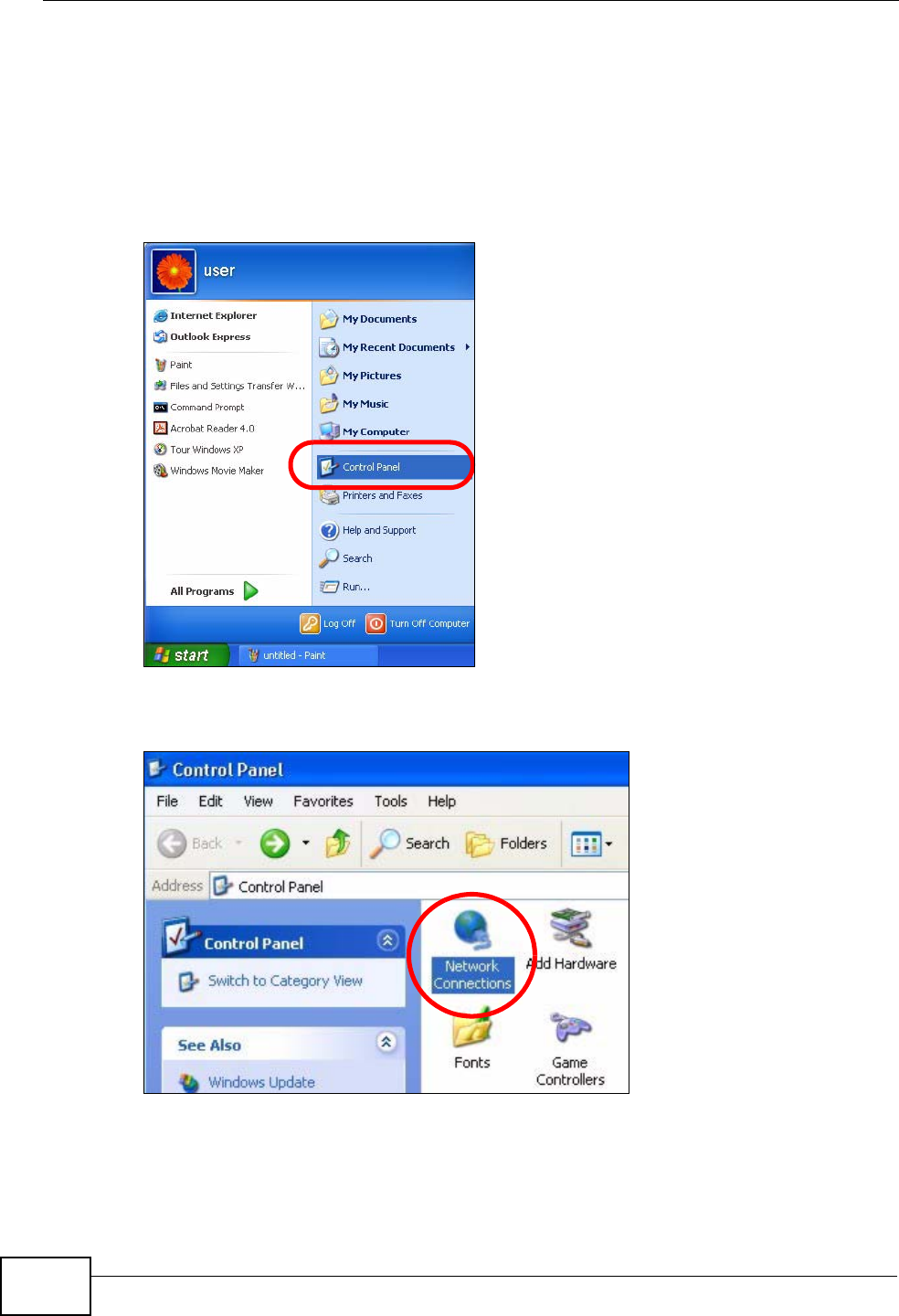
Appendix B Setting Up Your Computer’s IP Address
User’s Guide
262
Windows XP/NT/2000
The following example uses the default Windows XP display theme but can also
apply to Windows 2000 and Windows NT.
1Click Start > Control Panel.
Figure 96 Windows XP: Start Menu
2In the Control Panel, click the Network Connections icon.
Figure 97 Windows XP: Control Panel
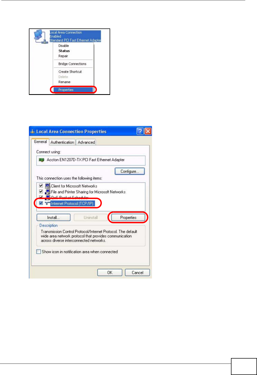
Appendix B Setting Up Your Computer’s IP Address
User’s Guide 263
3Right-click Local Area Connection and then select Properties.
Figure 98 Windows XP: Control Panel > Network Connections > Properties
4On the General tab, select Internet Protocol (TCP/IP) and then click
Properties.
Figure 99 Windows XP: Local Area Connection Properties
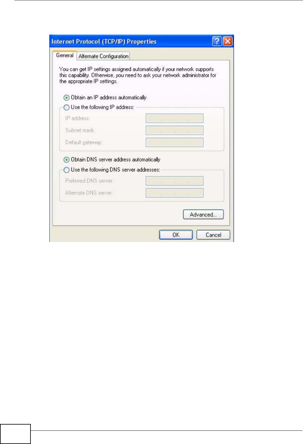
Appendix B Setting Up Your Computer’s IP Address
User’s Guide
264
5The Internet Protocol TCP/IP Properties window opens.
Figure 100 Windows XP: Internet Protocol (TCP/IP) Properties
6Select Obtain an IP address automatically if your network administrator or ISP
assigns your IP address dynamically.
Select Use the following IP Address and fill in the IP address, Subnet mask,
and Default gateway fields if you have a static IP address that was assigned to
you by your network administrator or ISP. You may also have to enter a
Preferred DNS server and an Alternate DNS server, if that information was
provided.
7Click OK to close the Internet Protocol (TCP/IP) Properties window.
Click OK to close the Local Area Connection Properties window.Verifying Settings
1Click Start > All Programs > Accessories > Command Prompt.
2In the Command Prompt window, type "ipconfig" and then press [ENTER].
You can also go to Start > Control Panel > Network Connections, right-click a
network connection, click Status and then click the Support tab to view your IP
address and connection information.
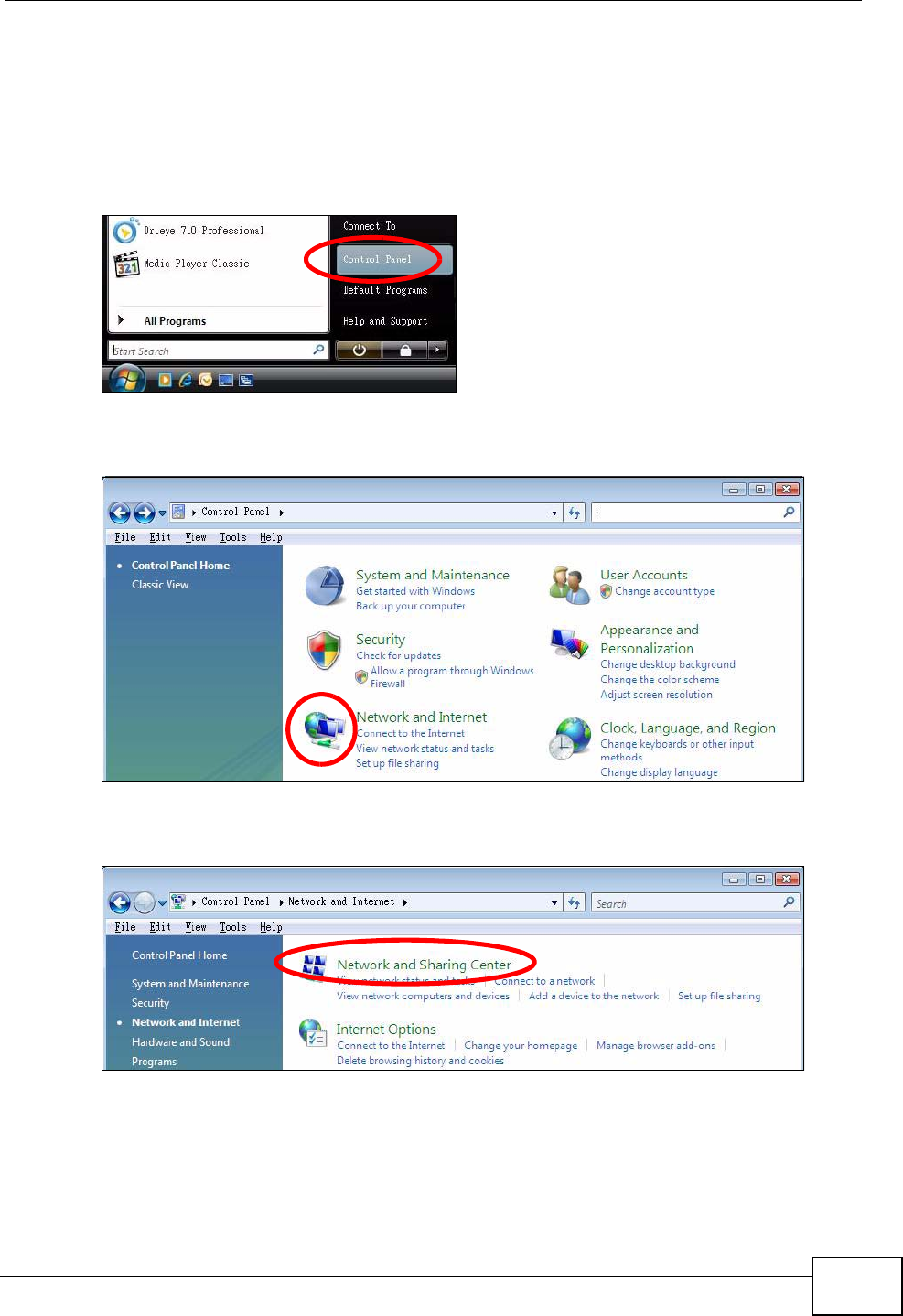
Appendix B Setting Up Your Computer’s IP Address
User’s Guide 265
Windows Vista
This section shows screens from Windows Vista Professional.
1Click Start > Control Panel.
Figure 101 Windows Vista: Start Menu
2In the Control Panel, click the Network and Internet icon.
Figure 102 Windows Vista: Control Panel
3Click the Network and Sharing Center icon.
Figure 103 Windows Vista: Network And Internet
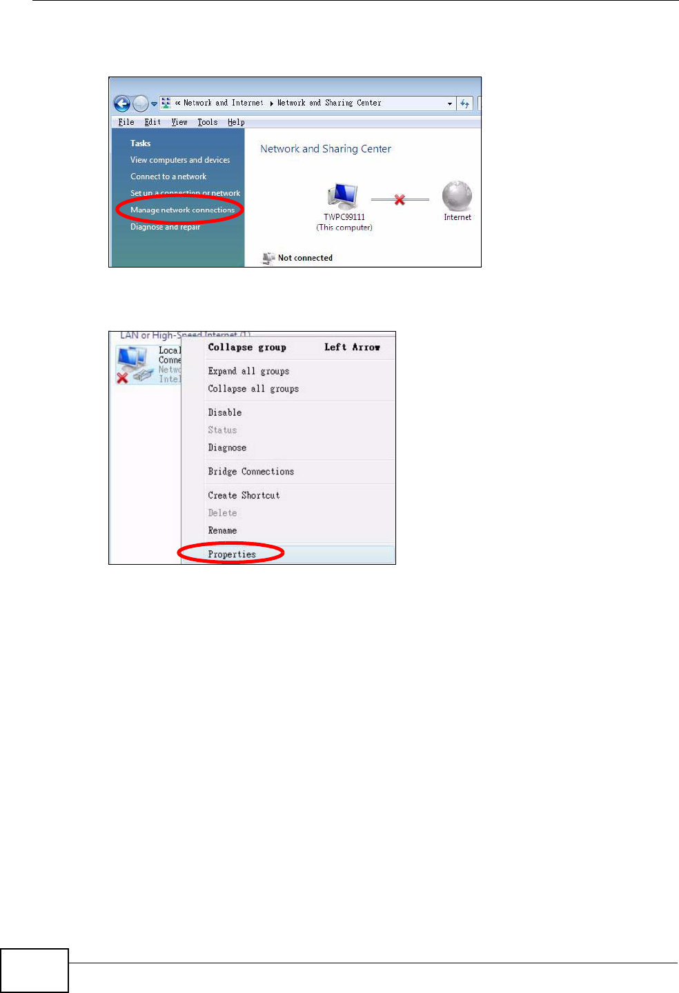
Appendix B Setting Up Your Computer’s IP Address
User’s Guide
266
4Click Manage network connections.
Figure 104 Windows Vista: Network and Sharing Center
5Right-click Local Area Connection and then select Properties.
Figure 105 Windows Vista: Network and Sharing Center
Note: During this procedure, click Continue whenever Windows displays a screen
saying that it needs your permission to continue.
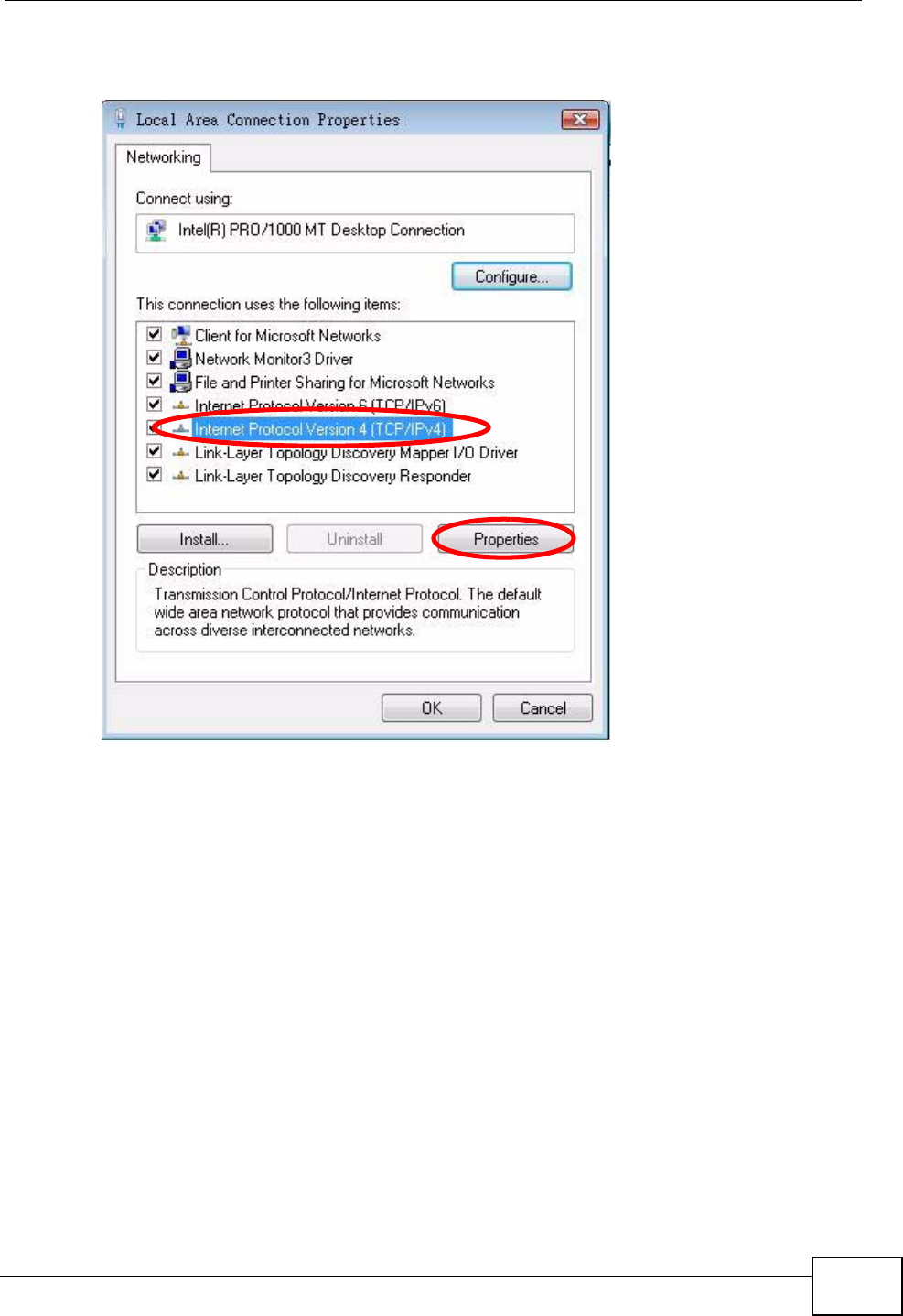
Appendix B Setting Up Your Computer’s IP Address
User’s Guide 267
6Select Internet Protocol Version 4 (TCP/IPv4) and then select Properties.
Figure 106 Windows Vista: Local Area Connection Properties
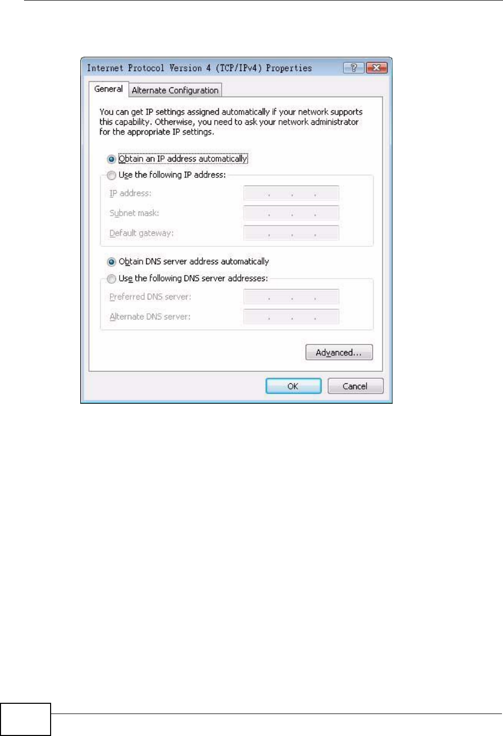
Appendix B Setting Up Your Computer’s IP Address
User’s Guide
268
7The Internet Protocol Version 4 (TCP/IPv4) Properties window opens.
Figure 107 Windows Vista: Internet Protocol Version 4 (TCP/IPv4) Properties
8Select Obtain an IP address automatically if your network administrator or ISP
assigns your IP address dynamically.
Select Use the following IP Address and fill in the IP address, Subnet mask,
and Default gateway fields if you have a static IP address that was assigned to
you by your network administrator or ISP. You may also have to enter a
Preferred DNS server and an Alternate DNS server, if that information was
provided.Click Advanced.
9Click OK to close the Internet Protocol (TCP/IP) Properties window.
Click OK to close the Local Area Connection Properties window.Verifying Settings
1Click Start > All Programs > Accessories > Command Prompt.
2In the Command Prompt window, type "ipconfig" and then press [ENTER].
You can also go to Start > Control Panel > Network Connections, right-click a
network connection, click Status and then click the Support tab to view your IP
address and connection information.
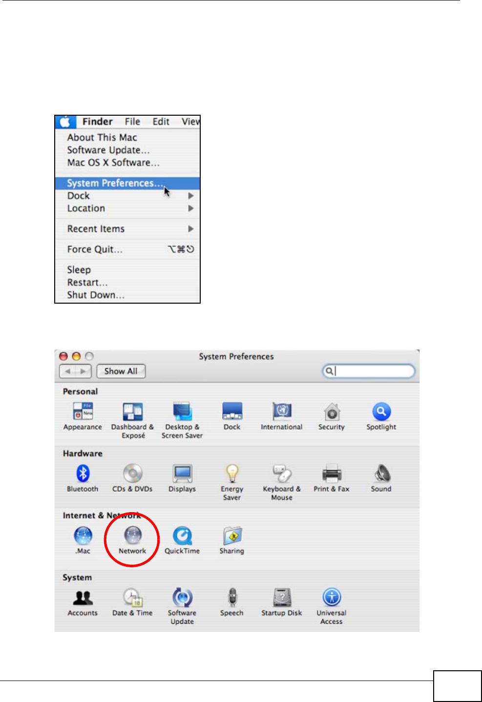
Appendix B Setting Up Your Computer’s IP Address
User’s Guide 269
Mac OS X: 10.3 and 10.4
The screens in this section are from Mac OS X 10.4 but can also apply to 10.3.
1Click Apple > System Preferences.
Figure 108 Mac OS X 10.4: Apple Menu
2In the System Preferences window, click the Network icon.
Figure 109 Mac OS X 10.4: System Preferences
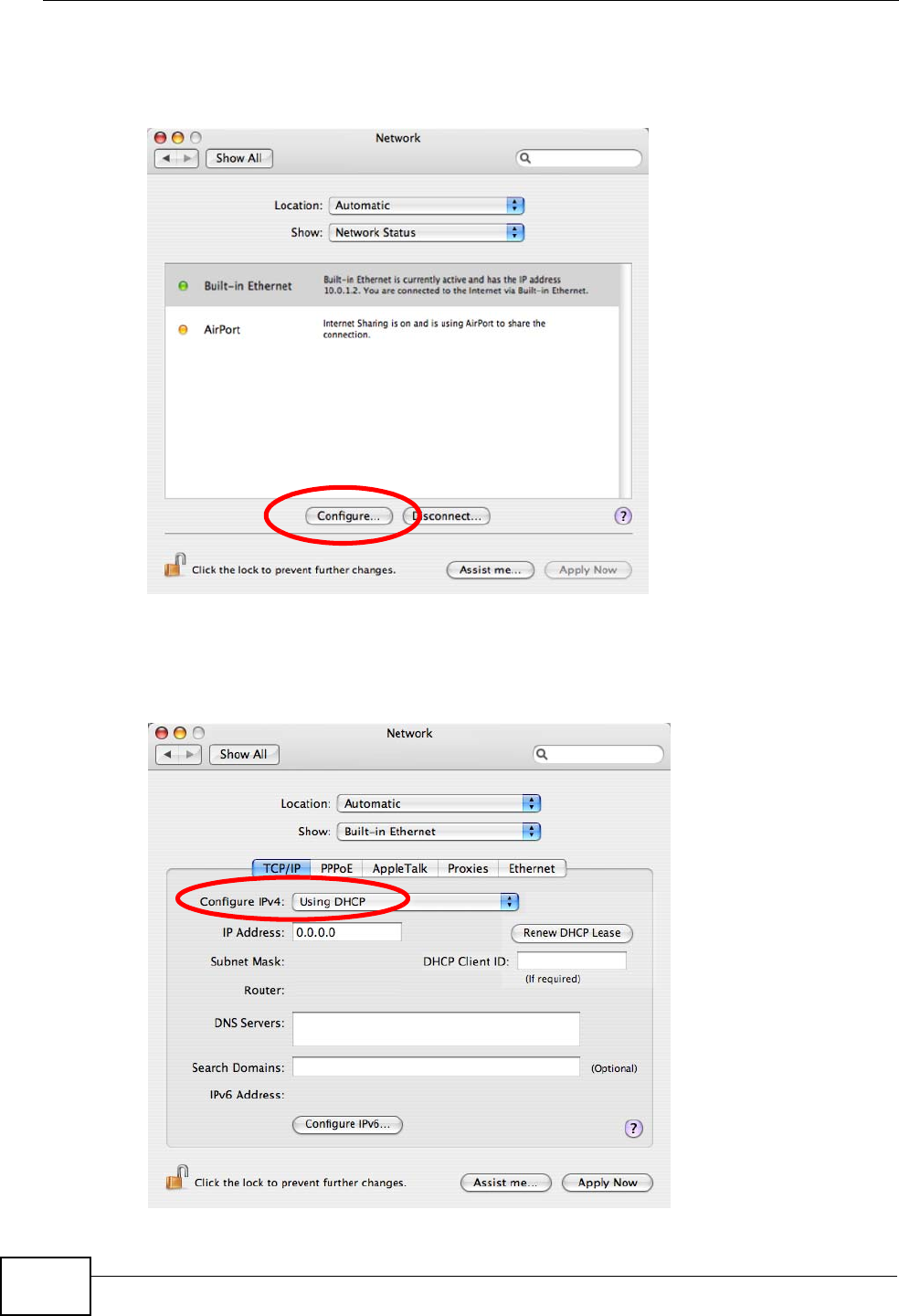
Appendix B Setting Up Your Computer’s IP Address
User’s Guide
270
3When the Network preferences pane opens, select Built-in Ethernet from the
network connection type list, and then click Configure.
Figure 110 Mac OS X 10.4: Network Preferences
4For dynamically assigned settings, select Using DHCP from the Configure IPv4
list in the TCP/IP tab.
Figure 111 Mac OS X 10.4: Network Preferences > TCP/IP Tab.
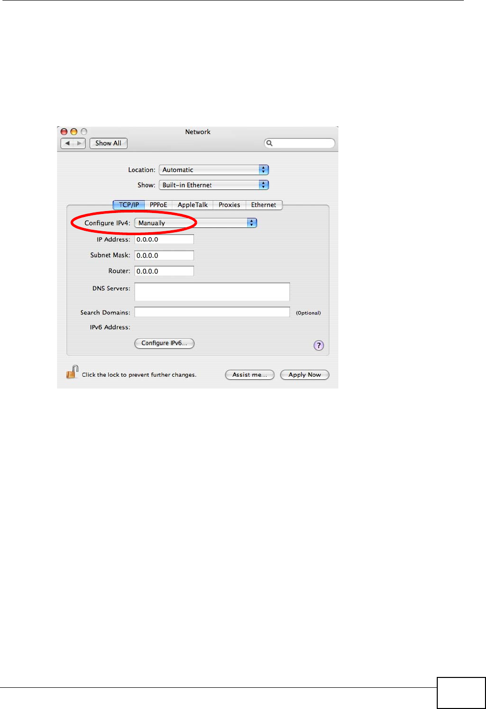
Appendix B Setting Up Your Computer’s IP Address
User’s Guide 271
5For statically assigned settings, do the following:
•From the Configure IPv4 list, select Manually.
•In the IP Address field, type your IP address.
•In the Subnet Mask field, type your subnet mask.
•In the Router field, type the IP address of your device.
Figure 112 Mac OS X 10.4: Network Preferences > Ethernet
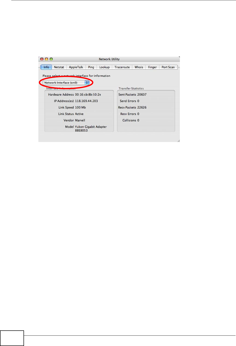
Appendix B Setting Up Your Computer’s IP Address
User’s Guide
272
Click Apply Now and close the window.Verifying Settings
Check your TCP/IP properties by clicking Applications > Utilities > Network
Utilities, and then selecting the appropriate Network Interface from the Info
tab.
Figure 113 Mac OS X 10.4: Network Utility
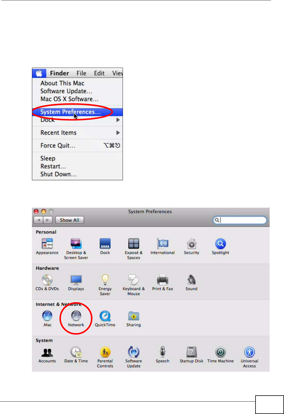
Appendix B Setting Up Your Computer’s IP Address
User’s Guide 273
Mac OS X: 10.5
The screens in this section are from Mac OS X 10.5.
1Click Apple > System Preferences.
Figure 114 Mac OS X 10.5: Apple Menu
2In System Preferences, click the Network icon.
Figure 115 Mac OS X 10.5: Systems Preferences
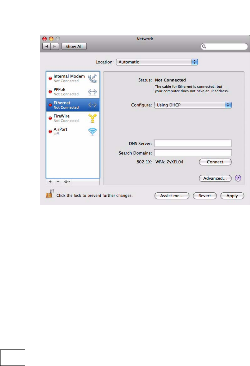
Appendix B Setting Up Your Computer’s IP Address
User’s Guide
274
3When the Network preferences pane opens, select Ethernet from the list of
available connection types.
Figure 116 Mac OS X 10.5: Network Preferences > Ethernet
4From the Configure list, select Using DHCP for dynamically assigned settings.
5For statically assigned settings, do the following:
•From the Configure list, select Manually.
•In the IP Address field, enter your IP address.
•In the Subnet Mask field, enter your subnet mask.
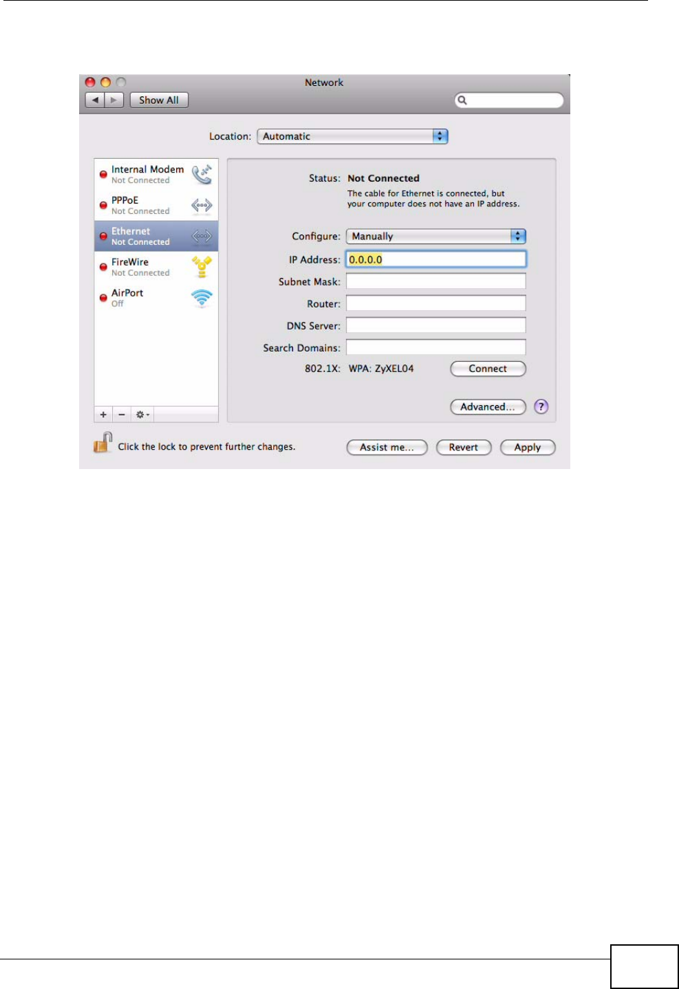
Appendix B Setting Up Your Computer’s IP Address
User’s Guide 275
•In the Router field, enter the IP address of your WiMAX Modem.
Figure 117 Mac OS X 10.5: Network Preferences > Ethernet
6Click Apply and close the window.
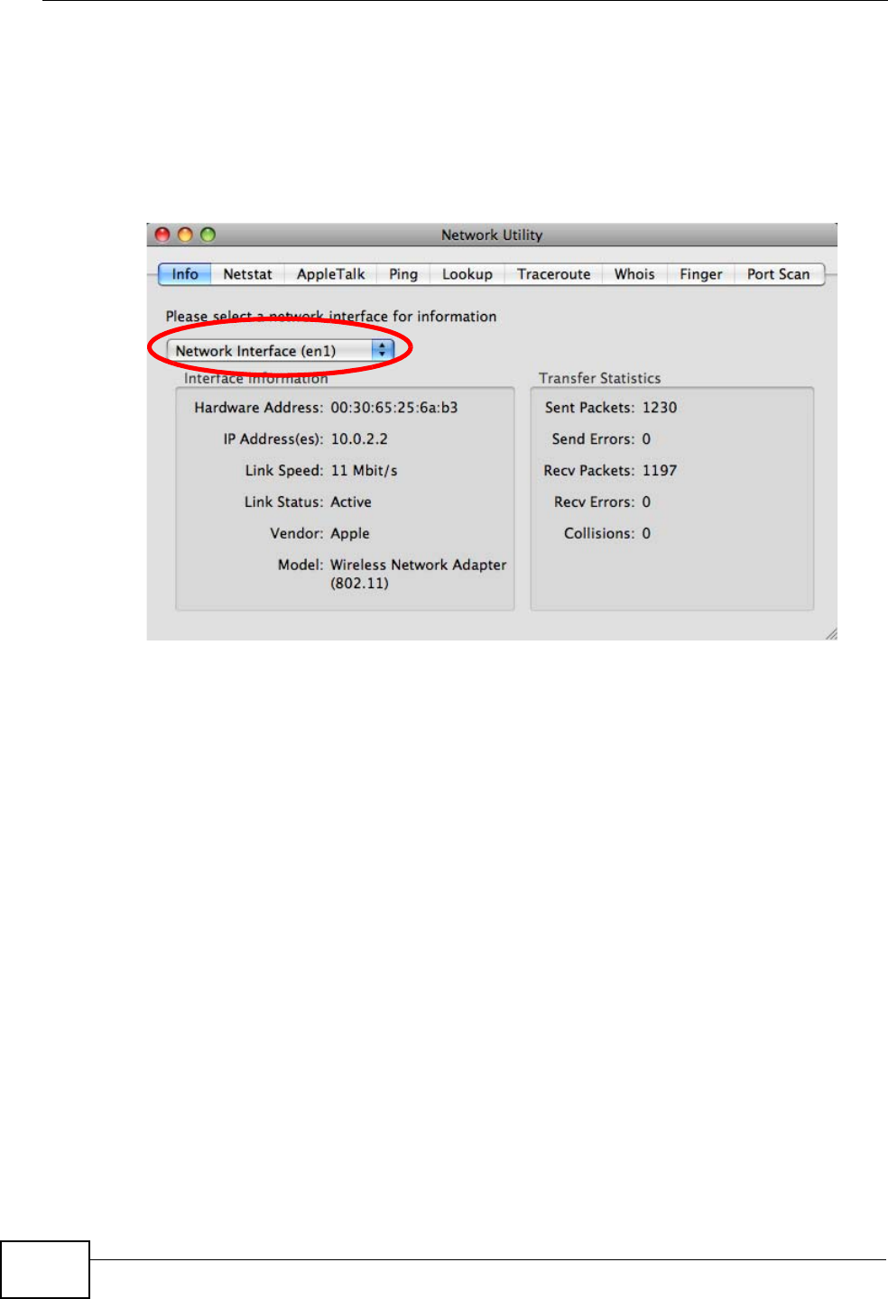
Appendix B Setting Up Your Computer’s IP Address
User’s Guide
276
Verifying Settings
Check your TCP/IP properties by clicking Applications > Utilities > Network
Utilities, and then selecting the appropriate Network interface from the Info
tab.
Figure 118 Mac OS X 10.5: Network Utility
Linux: Ubuntu 8 (GNOME)
This section shows you how to configure your computer’s TCP/IP settings in the
GNU Object Model Environment (GNOME) using the Ubuntu 8 Linux distribution.
The procedure, screens and file locations may vary depending on your specific
distribution, release version, and individual configuration. The following screens
use the default Ubuntu 8 installation.
Note: Make sure you are logged in as the root administrator.
Follow the steps below to configure your computer IP address in GNOME:
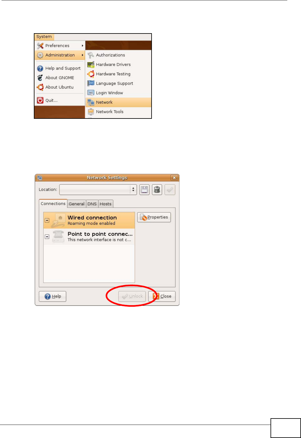
Appendix B Setting Up Your Computer’s IP Address
User’s Guide 277
1Click System > Administration > Network.
Figure 119 Ubuntu 8: System > Administration Menu
2When the Network Settings window opens, click Unlock to open the
Authenticate window. (By default, the Unlock button is greyed out until clicked.)
You cannot make changes to your configuration unless you first enter your admin
password.
Figure 120 Ubuntu 8: Network Settings > Connections
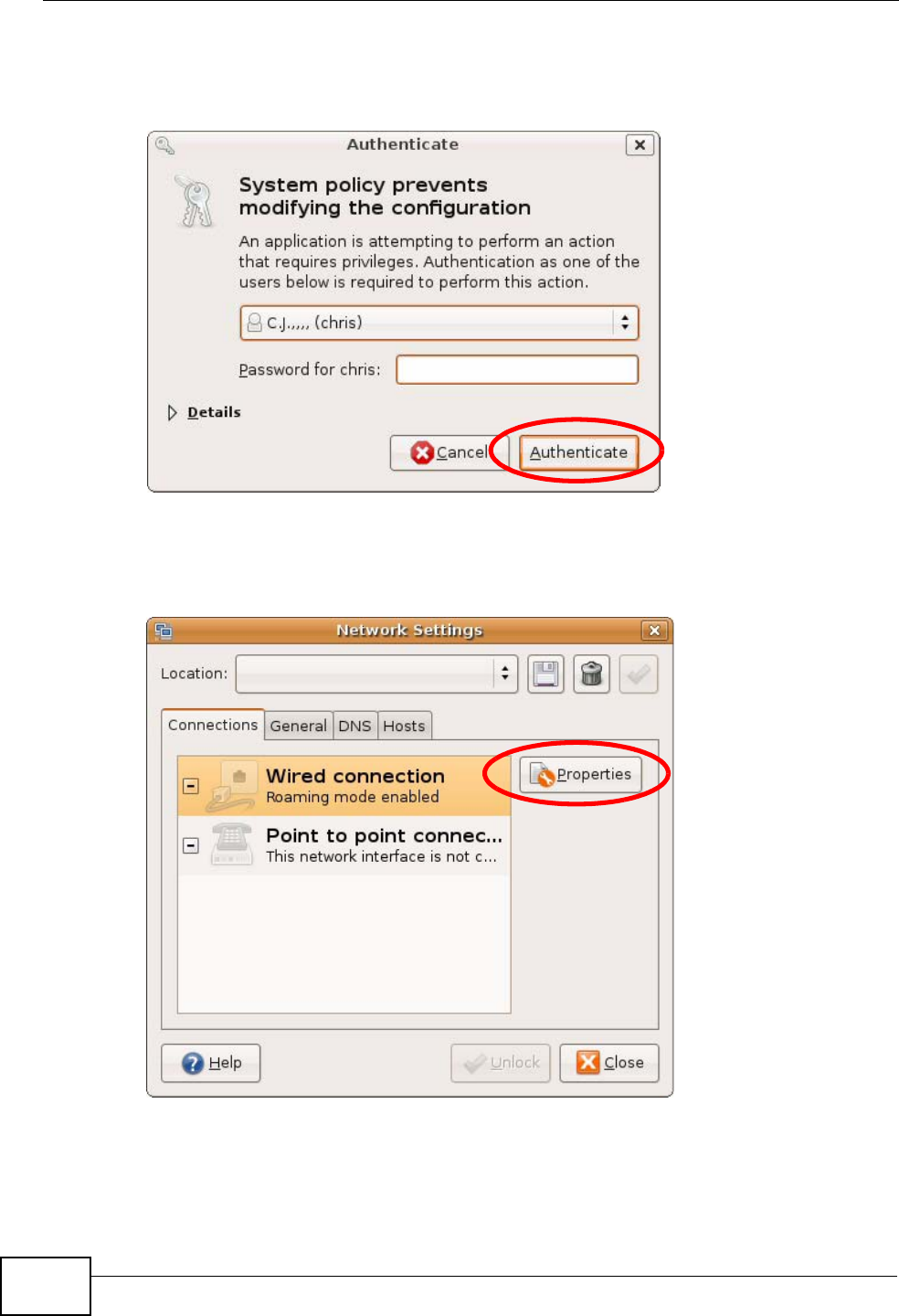
Appendix B Setting Up Your Computer’s IP Address
User’s Guide
278
3In the Authenticate window, enter your admin account name and password then
click the Authenticate button.
Figure 121 Ubuntu 8: Administrator Account Authentication
4In the Network Settings window, select the connection that you want to
configure, then click Properties.
Figure 122 Ubuntu 8: Network Settings > Connections
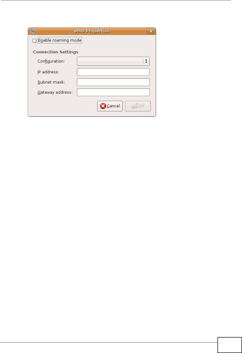
Appendix B Setting Up Your Computer’s IP Address
User’s Guide 279
5The Properties dialog box opens.
Figure 123 Ubuntu 8: Network Settings > Properties
•In the Configuration list, select Automatic Configuration (DHCP) if you
have a dynamic IP address.
•In the Configuration list, select Static IP address if you have a static IP
address. Fill in the IP address, Subnet mask, and Gateway address fields.
6Click OK to save the changes and close the Properties dialog box and return to
the Network Settings screen.
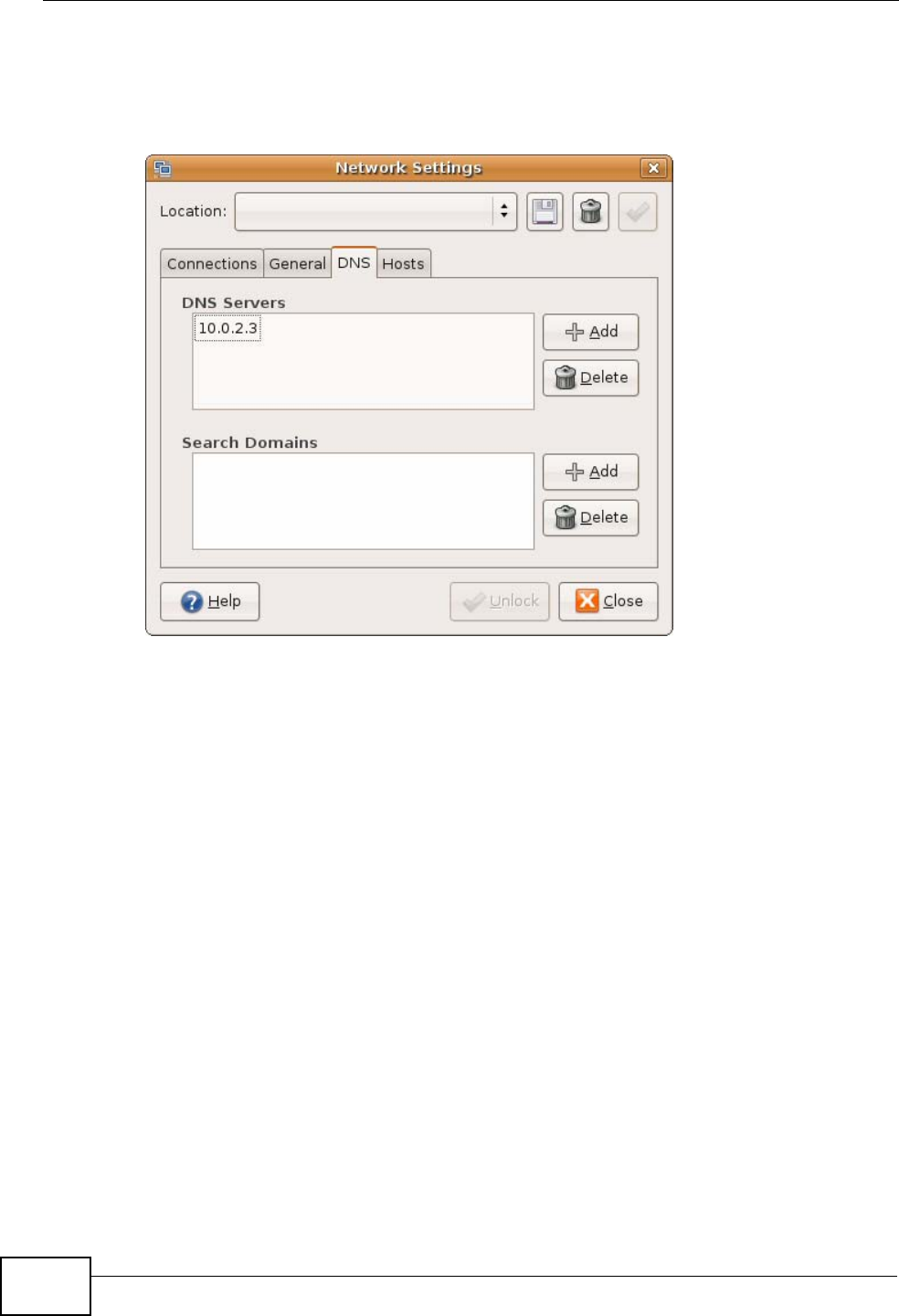
Appendix B Setting Up Your Computer’s IP Address
User’s Guide
280
7If you know your DNS server IP address(es), click the DNS tab in the Network
Settings window and then enter the DNS server information in the fields
provided.
Figure 124 Ubuntu 8: Network Settings > DNS
8Click the Close button to apply the changes.
Verifying Settings
Check your TCP/IP properties by clicking System > Administration > Network
Tools, and then selecting the appropriate Network device from the Devices
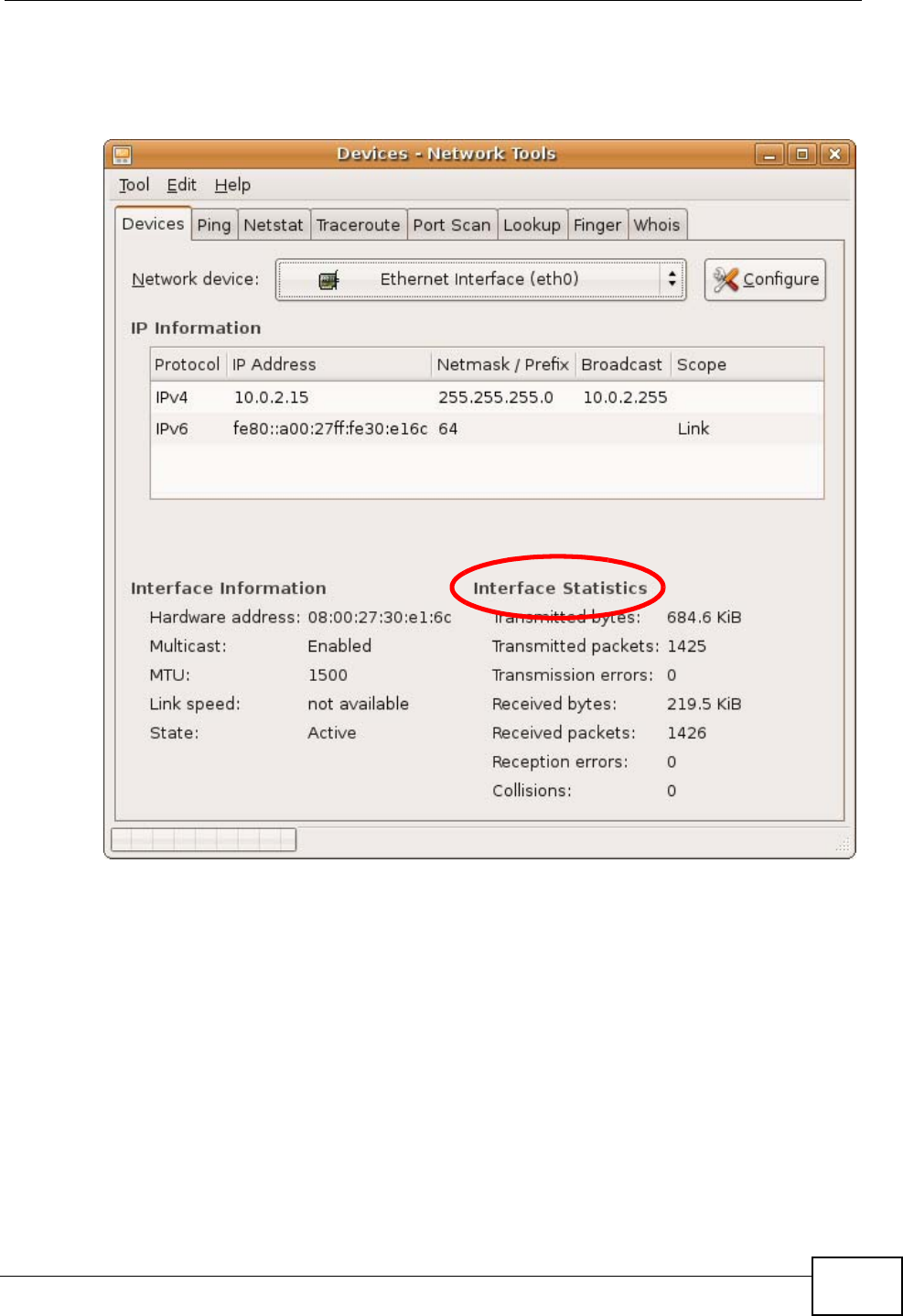
Appendix B Setting Up Your Computer’s IP Address
User’s Guide 281
tab. The Interface Statistics column shows data if your connection is working
properly.
Figure 125 Ubuntu 8: Network Tools
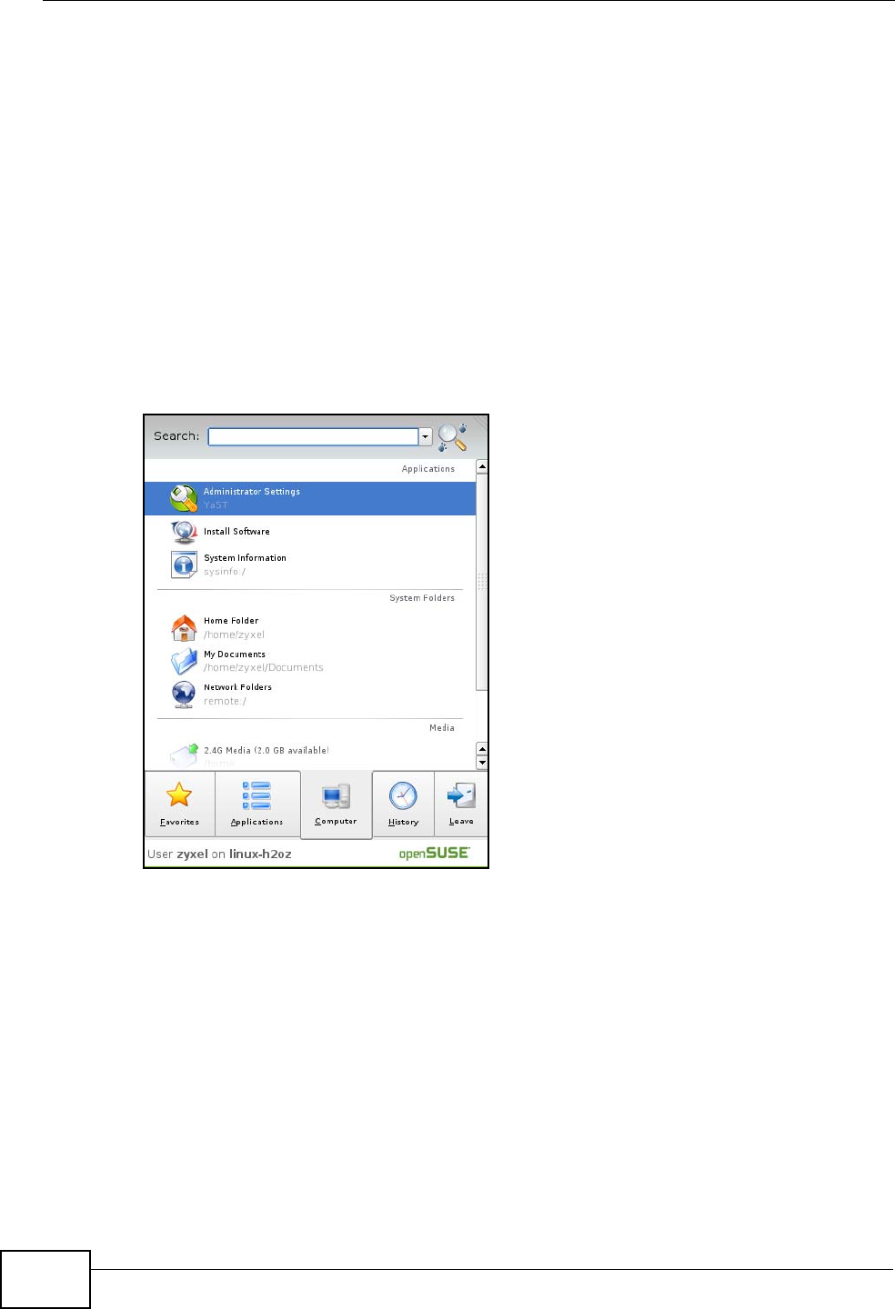
Appendix B Setting Up Your Computer’s IP Address
User’s Guide
282
Linux: openSUSE 10.3 (KDE)
This section shows you how to configure your computer’s TCP/IP settings in the K
Desktop Environment (KDE) using the openSUSE 10.3 Linux distribution. The
procedure, screens and file locations may vary depending on your specific
distribution, release version, and individual configuration. The following screens
use the default openSUSE 10.3 installation.
Note: Make sure you are logged in as the root administrator.
Follow the steps below to configure your computer IP address in the KDE:
1Click K Menu > Computer > Administrator Settings (YaST).
Figure 126 openSUSE 10.3: K Menu > Computer Menu
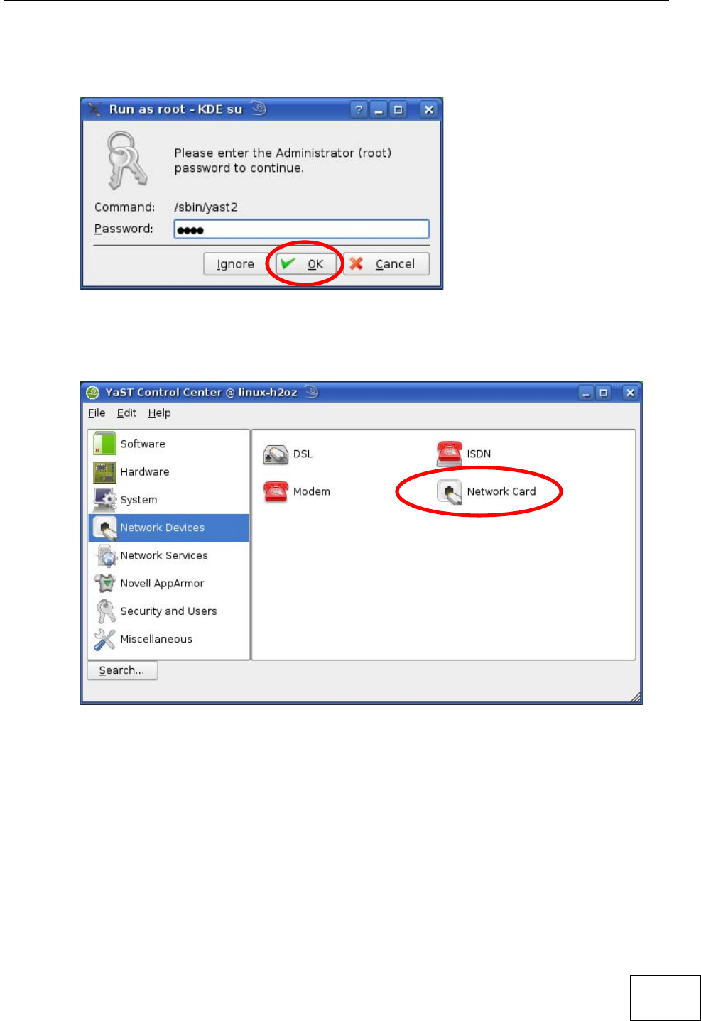
Appendix B Setting Up Your Computer’s IP Address
User’s Guide 283
2When the Run as Root - KDE su dialog opens, enter the admin password and
click OK.
Figure 127 openSUSE 10.3: K Menu > Computer Menu
3When the YaST Control Center window opens, select Network Devices and
then click the Network Card icon.
Figure 128 openSUSE 10.3: YaST Control Center
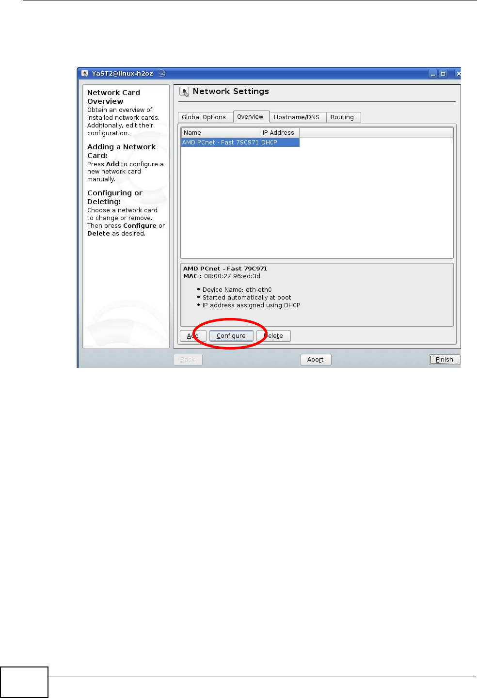
Appendix B Setting Up Your Computer’s IP Address
User’s Guide
284
4When the Network Settings window opens, click the Overview tab, select the
appropriate connection Name from the list, and then click the Configure button.
Figure 129 openSUSE 10.3: Network Settings
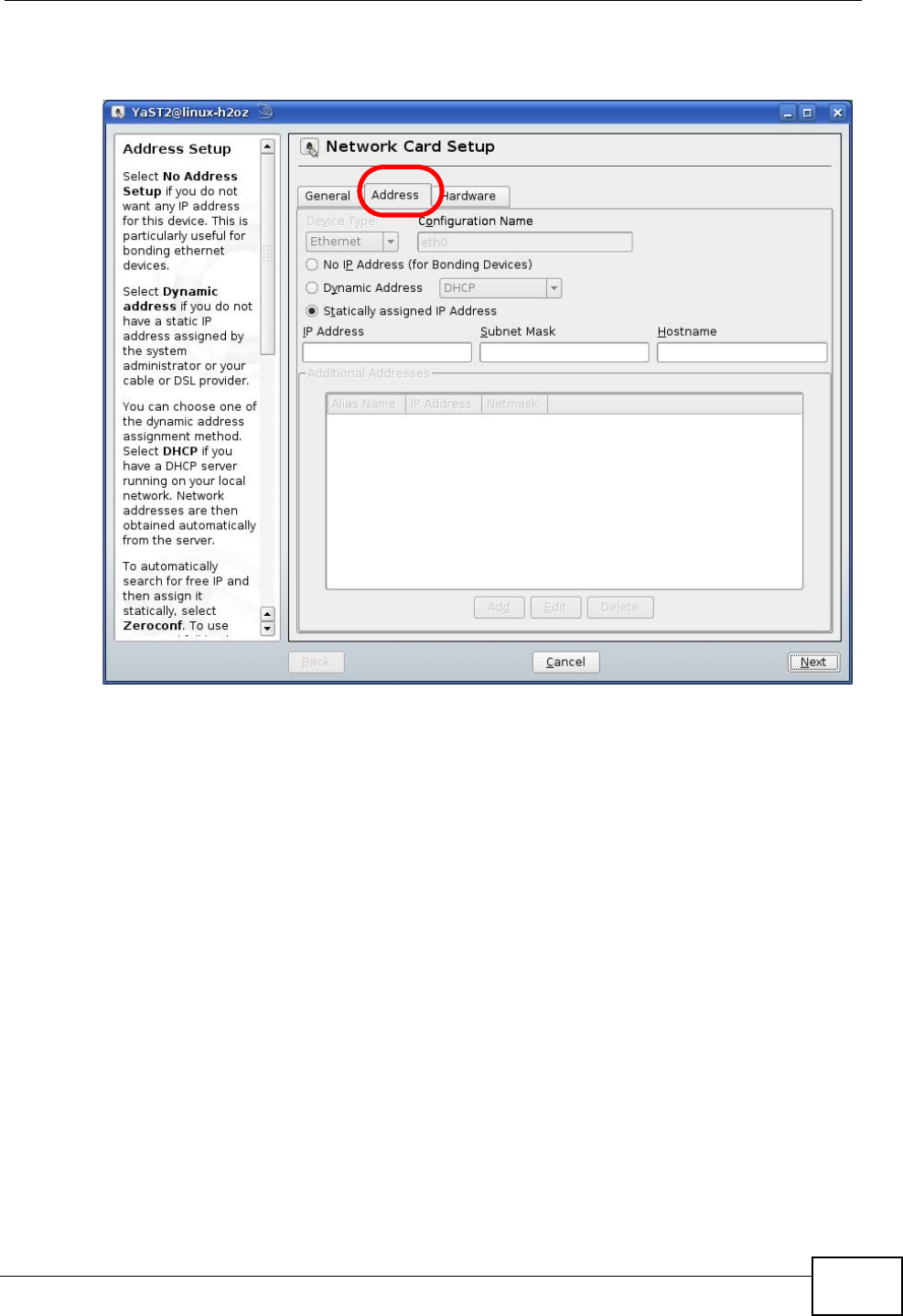
Appendix B Setting Up Your Computer’s IP Address
User’s Guide 285
5When the Network Card Setup window opens, click the Address tab
Figure 130 openSUSE 10.3: Network Card Setup
6Select Dynamic Address (DHCP) if you have a dynamic IP address.
Select Statically assigned IP Address if you have a static IP address. Fill in the
IP address, Subnet mask, and Hostname fields.
7Click Next to save the changes and close the Network Card Setup window.
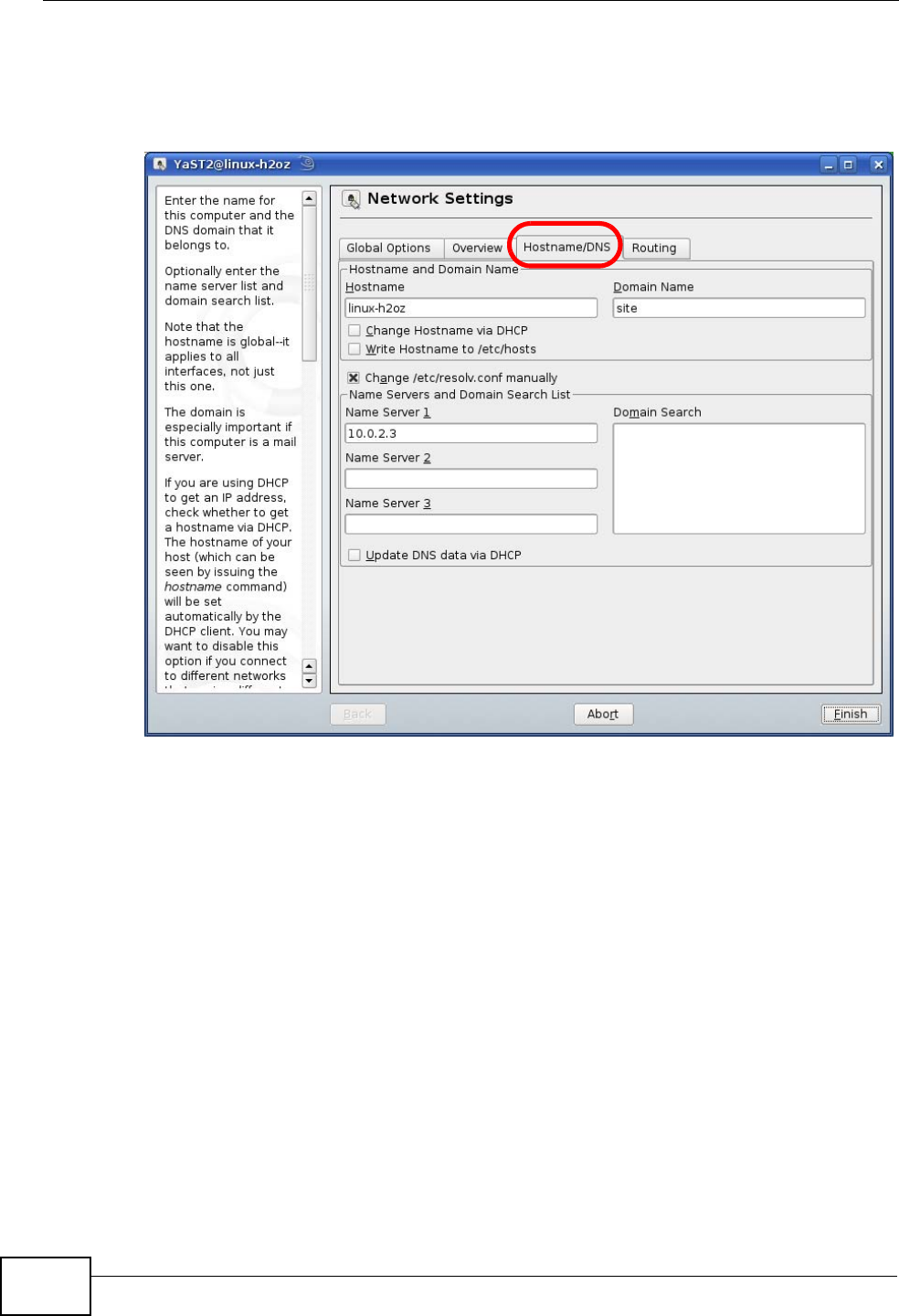
Appendix B Setting Up Your Computer’s IP Address
User’s Guide
286
8If you know your DNS server IP address(es), click the Hostname/DNS tab in
Network Settings and then enter the DNS server information in the fields
provided.
Figure 131 openSUSE 10.3: Network Settings
9Click Finish to save your settings and close the window.
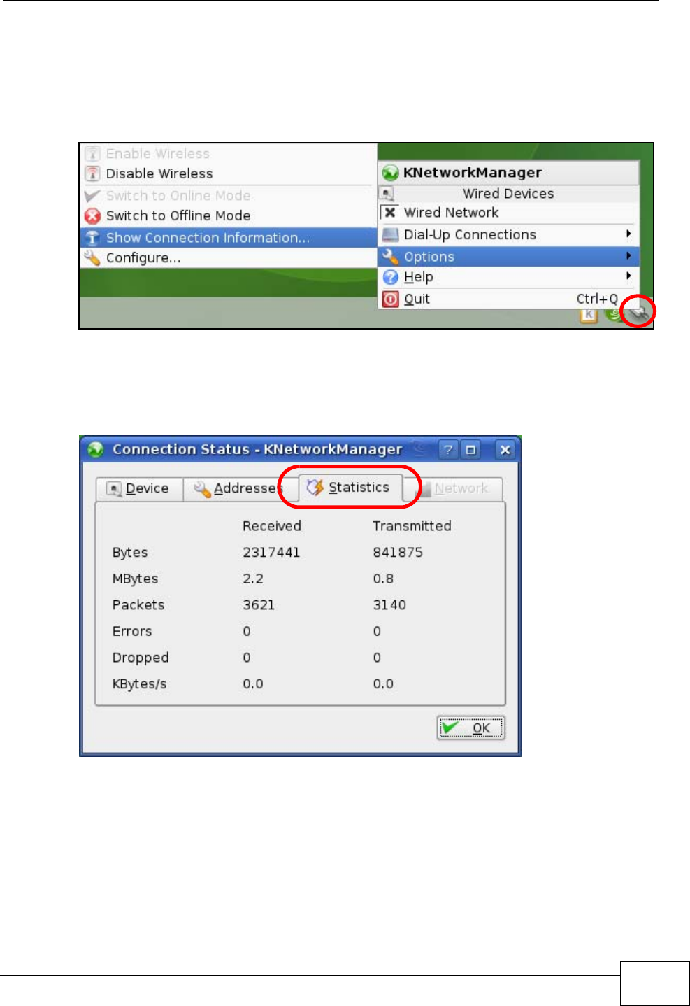
Appendix B Setting Up Your Computer’s IP Address
User’s Guide 287
Verifying Settings
Click the KNetwork Manager icon on the Task bar to check your TCP/IP
properties. From the Options sub-menu, select Show Connection Information.
Figure 132 openSUSE 10.3: KNetwork Manager
When the Connection Status - KNetwork Manager window opens, click the
Statistics tab to see if your connection is working properly.
Figure 133 openSUSE: Connection Status - KNetwork Manager

Appendix B Setting Up Your Computer’s IP Address
User’s Guide
288
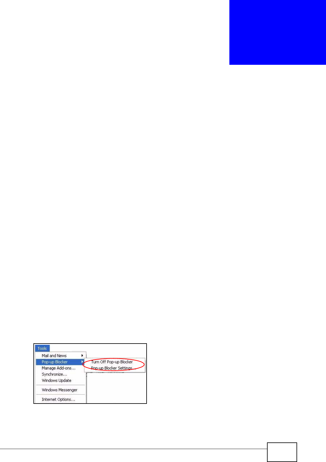
User’s Guide 289
APPENDIX C
Pop-up Windows, JavaScripts
and Java Permissions
In order to use the web configurator you need to allow:
• Web browser pop-up windows from your device.
• JavaScripts (enabled by default).
• Java permissions (enabled by default).
Note: Internet Explorer 6 screens are used here. Screens for other Internet Explorer
versions may vary.
Internet Explorer Pop-up Blockers
You may have to disable pop-up blocking to log into your device.
Either disable pop-up blocking (enabled by default in Windows XP SP (Service
Pack) 2) or allow pop-up blocking and create an exception for your device’s IP
address.
Disable Pop-up Blockers
1In Internet Explorer, select Tools, Pop-up Blocker and then select Turn Off
Pop-up Blocker.
Figure 134 Pop-up Blocker
You can also check if pop-up blocking is disabled in the Pop-up Blocker section in
the Privacy tab.
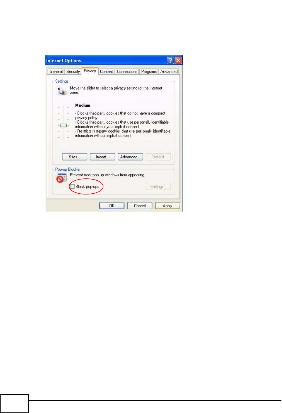
Appendix C Pop-up Windows, JavaScripts and Java Permissions
User’s Guide
290
1In Internet Explorer, select Tools, Internet Options, Privacy.
2Clear the Block pop-ups check box in the Pop-up Blocker section of the screen.
This disables any web pop-up blockers you may have enabled.
Figure 135 Internet Options: Privacy
3Click Apply to save this setting.
Enable Pop-up Blockers with Exceptions
Alternatively, if you only want to allow pop-up windows from your device, see the
following steps.
1In Internet Explorer, select Tools, Internet Options and then the Privacy tab.
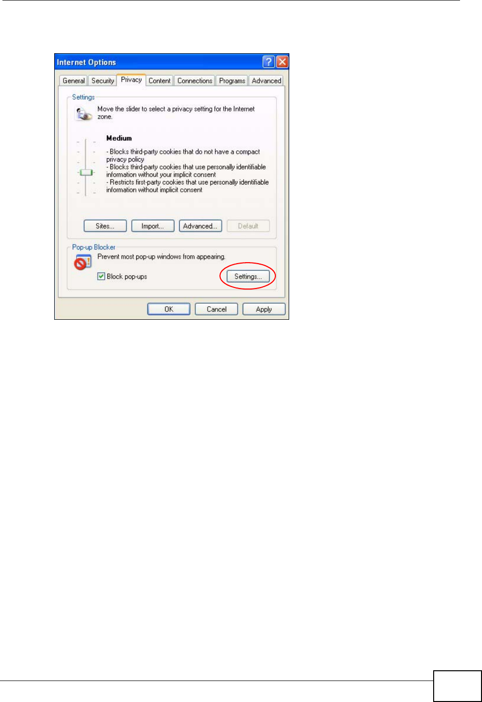
Appendix C Pop-up Windows, JavaScripts and Java Permissions
User’s Guide 291
2Select Settings…to open the Pop-up Blocker Settings screen.
Figure 136 Internet Options: Privacy
3Type the IP address of your device (the web page that you do not want to have
blocked) with the prefix “http://”. For example, http://192.168.167.1.
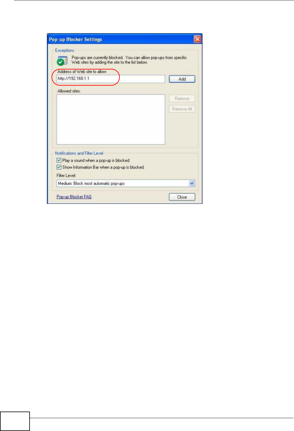
Appendix C Pop-up Windows, JavaScripts and Java Permissions
User’s Guide
292
4Click Add to move the IP address to the list of Allowed sites.
Figure 137 Pop-up Blocker Settings
5Click Close to return to the Privacy screen.
6Click Apply to save this setting.
JavaScripts
If pages of the web configurator do not display properly in Internet Explorer,
check that JavaScripts are allowed.
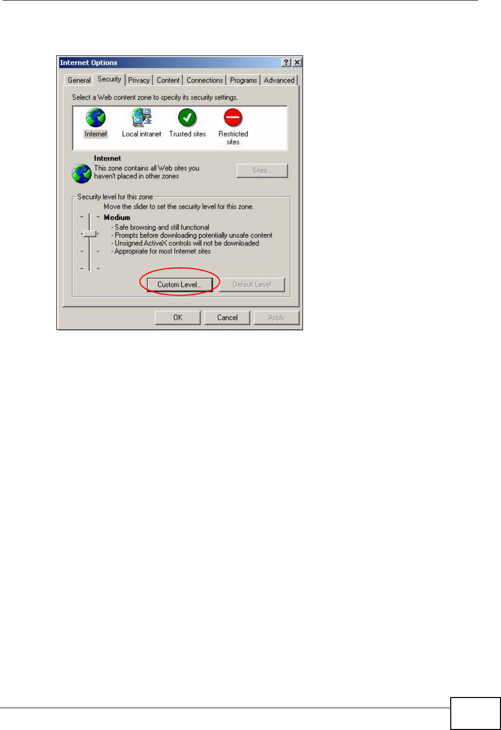
Appendix C Pop-up Windows, JavaScripts and Java Permissions
User’s Guide 293
1In Internet Explorer, click Tools, Internet Options and then the Security tab.
Figure 138 Internet Options: Security
2Click the Custom Level... button.
3Scroll down to Scripting.
4Under Active scripting make sure that Enable is selected (the default).
5Under Scripting of Java applets make sure that Enable is selected (the
default).
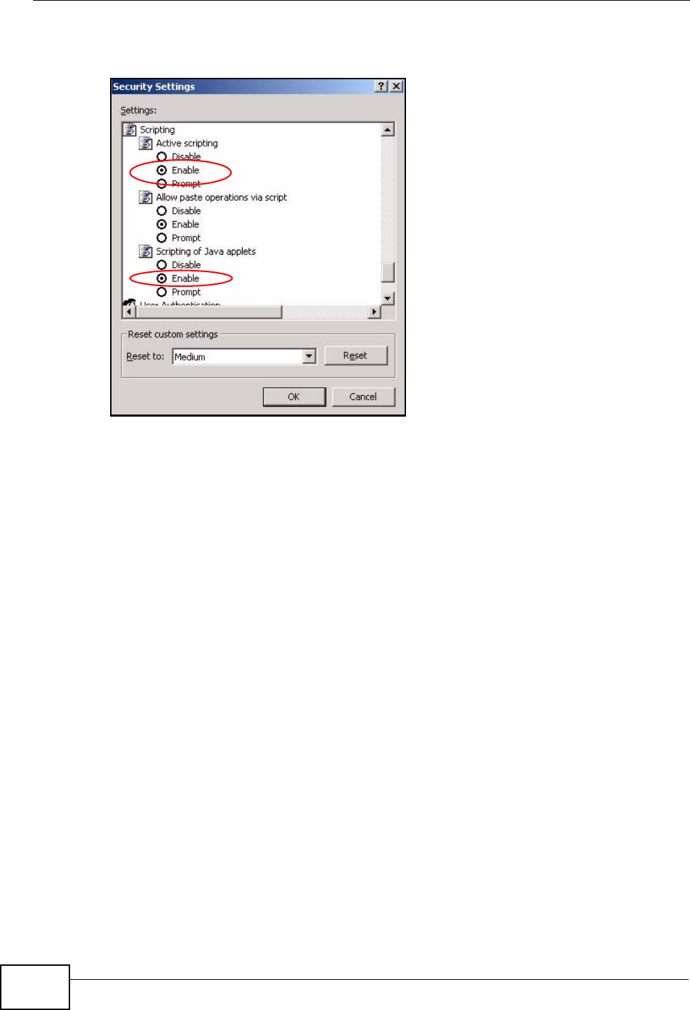
Appendix C Pop-up Windows, JavaScripts and Java Permissions
User’s Guide
294
6Click OK to close the window.
Figure 139 Security Settings - Java Scripting
Java Permissions
1From Internet Explorer, click Tools, Internet Options and then the Security
tab.
2Click the Custom Level... button.
3Scroll down to Microsoft VM.
4Under Java permissions make sure that a safety level is selected.
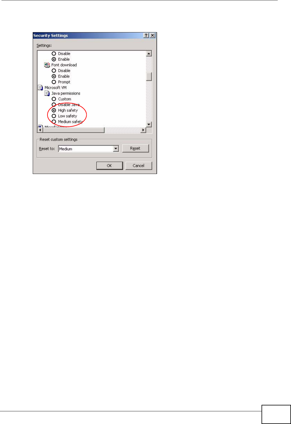
Appendix C Pop-up Windows, JavaScripts and Java Permissions
User’s Guide 295
5Click OK to close the window.
Figure 140 Security Settings - Java
JAVA (Sun)
1From Internet Explorer, click Tools, Internet Options and then the Advanced
tab.
2Make sure that Use Java 2 for <applet> under Java (Sun) is selected.
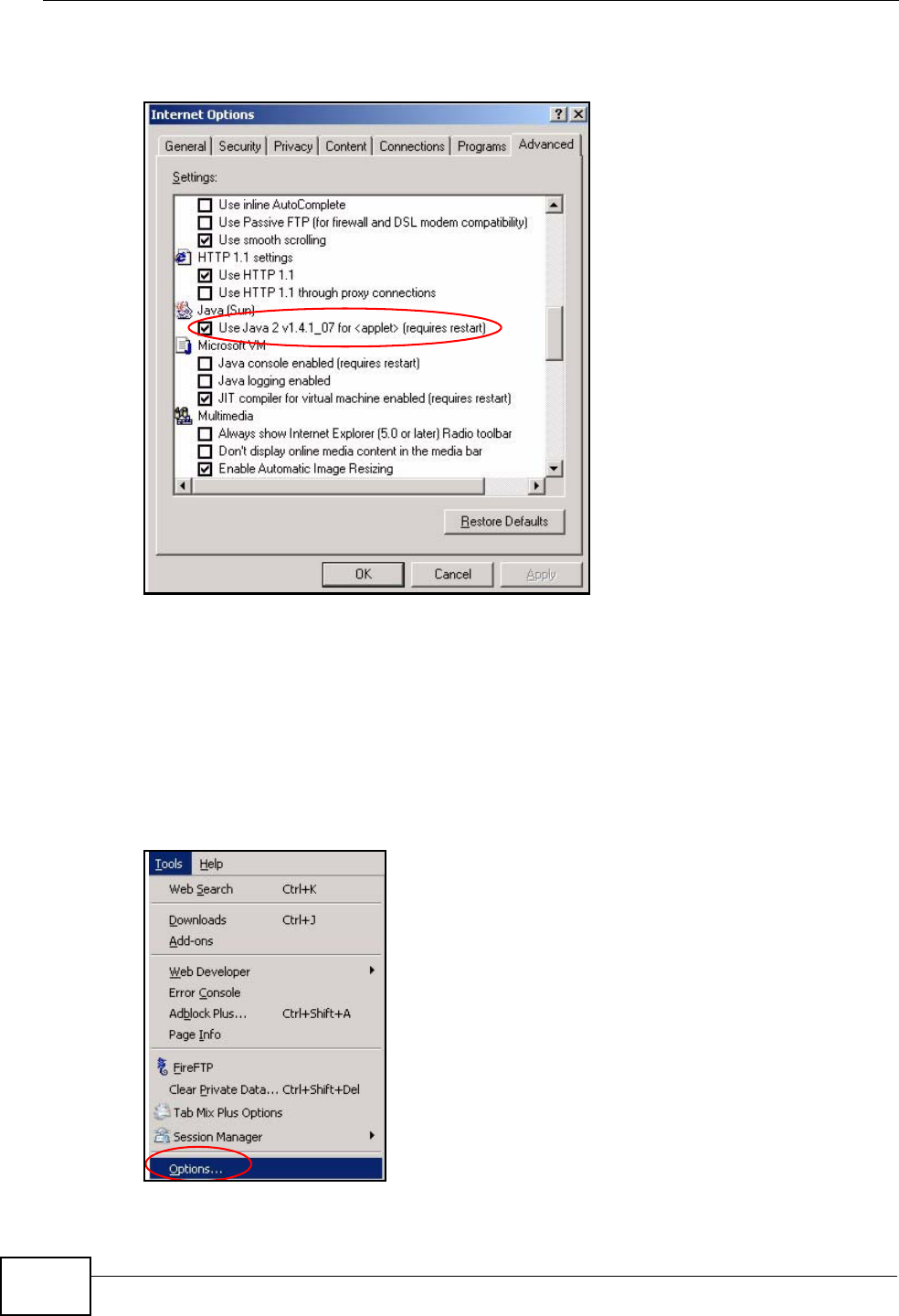
Appendix C Pop-up Windows, JavaScripts and Java Permissions
User’s Guide
296
3Click OK to close the window.
Figure 141 Java (Sun)
Mozilla Firefox
Mozilla Firefox 2.0 screens are used here. Screens for other versions may vary.
You can enable Java, Javascripts and pop-ups in one screen. Click Tools, then
click Options in the screen that appears.
Figure 142 Mozilla Firefox: TOOLS > Options
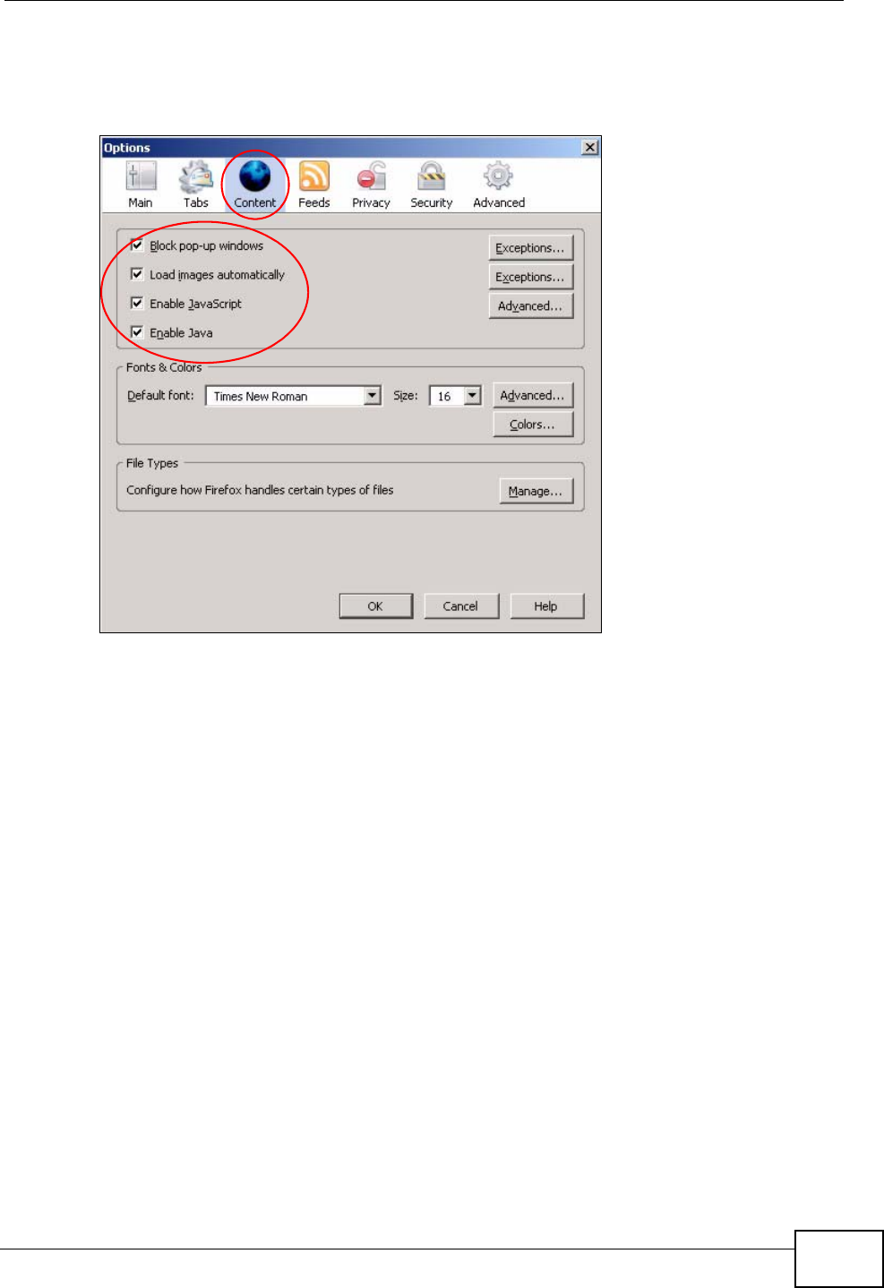
Appendix C Pop-up Windows, JavaScripts and Java Permissions
User’s Guide 297
Click Content.to show the screen below. Select the check boxes as shown in the
following screen.
Figure 143 Mozilla Firefox Content Security

Appendix C Pop-up Windows, JavaScripts and Java Permissions
User’s Guide
298

User’s Guide 299
APPENDIX D
IP Addresses and Subnetting
This appendix introduces IP addresses and subnet masks.
IP addresses identify individual devices on a network. Every networking device
(including computers, servers, routers, printers, etc.) needs an IP address to
communicate across the network. These networking devices are also known as
hosts.
Subnet masks determine the maximum number of possible hosts on a network.
You can also use subnet masks to divide one network into multiple sub-networks.
Introduction to IP Addresses
One part of the IP address is the network number, and the other part is the host
ID. In the same way that houses on a street share a common street name, the
hosts on a network share a common network number. Similarly, as each house
has its own house number, each host on the network has its own unique
identifying number - the host ID. Routers use the network number to send
packets to the correct network, while the host ID determines to which host on the
network the packets are delivered.
Structure
An IP address is made up of four parts, written in dotted decimal notation (for
example, 192.168.1.1). Each of these four parts is known as an octet. An octet is
an eight-digit binary number (for example 11000000, which is 192 in decimal
notation).
Therefore, each octet has a possible range of 00000000 to 11111111 in binary, or
0 to 255 in decimal.
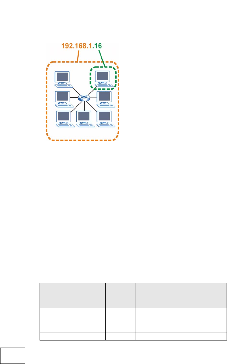
Appendix D IP Addresses and Subnetting
User’s Guide
300
The following figure shows an example IP address in which the first three octets
(192.168.1) are the network number, and the fourth octet (16) is the host ID.
Figure 144 Network Number and Host ID
How much of the IP address is the network number and how much is the host ID
varies according to the subnet mask.
Subnet Masks
A subnet mask is used to determine which bits are part of the network number,
and which bits are part of the host ID (using a logical AND operation). The term
“subnet” is short for “sub-network”.
A subnet mask has 32 bits. If a bit in the subnet mask is a “1” then the
corresponding bit in the IP address is part of the network number. If a bit in the
subnet mask is “0” then the corresponding bit in the IP address is part of the host
ID.
The following example shows a subnet mask identifying the network number (in
bold text) and host ID of an IP address (192.168.1.2 in decimal).
Table 114 IP Address Network Number and Host ID Example
1ST
OCTET:
(192)
2ND
OCTET:
(168)
3RD
OCTET:
(1)
4TH
OCTET
(2)
IP Address (Binary) 11000000 10101000 00000001 00000010
Subnet Mask (Binary) 11111111 11111111 11111111 00000000
Network Number 11000000 10101000 00000001
Host ID 00000010
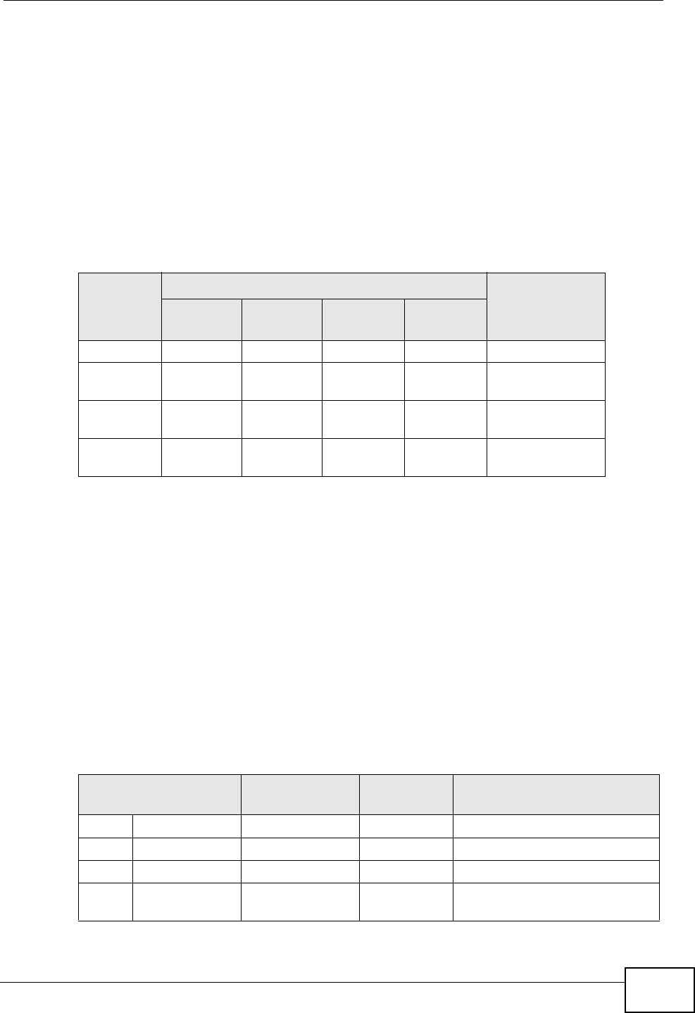
Appendix D IP Addresses and Subnetting
User’s Guide 301
By convention, subnet masks always consist of a continuous sequence of ones
beginning from the leftmost bit of the mask, followed by a continuous sequence of
zeros, for a total number of 32 bits.
Subnet masks can be referred to by the size of the network number part (the bits
with a “1” value). For example, an “8-bit mask” means that the first 8 bits of the
mask are ones and the remaining 24 bits are zeroes.
Subnet masks are expressed in dotted decimal notation just like IP addresses. The
following examples show the binary and decimal notation for 8-bit, 16-bit, 24-bit
and 29-bit subnet masks.
Network Size
The size of the network number determines the maximum number of possible
hosts you can have on your network. The larger the number of network number
bits, the smaller the number of remaining host ID bits.
An IP address with host IDs of all zeros is the IP address of the network
(192.168.1.0 with a 24-bit subnet mask, for example). An IP address with host
IDs of all ones is the broadcast address for that network (192.168.1.255 with a
24-bit subnet mask, for example).
As these two IP addresses cannot be used for individual hosts, calculate the
maximum number of possible hosts in a network as follows:
Table 115 Subnet Masks
BINARY
DECIMAL
1ST
OCTET 2ND
OCTET 3RD
OCTET 4TH
OCTET
8-bit mask 11111111 00000000 00000000 00000000 255.0.0.0
16-bit
mask 11111111 11111111 00000000 00000000 255.255.0.0
24-bit
mask 11111111 11111111 11111111 00000000 255.255.255.0
29-bit
mask 11111111 11111111 11111111 11111000 255.255.255.24
8
Table 116 Maximum Host Numbers
SUBNET MASK HOST ID SIZE MAXIMUM NUMBER OF
HOSTS
8 bits 255.0.0.0 24 bits 224 – 2 16777214
16 bits 255.255.0.0 16 bits 216 – 2 65534
24 bits 255.255.255.0 8 bits 28 – 2 254
29 bits 255.255.255.2
48 3 bits 23 – 2 6
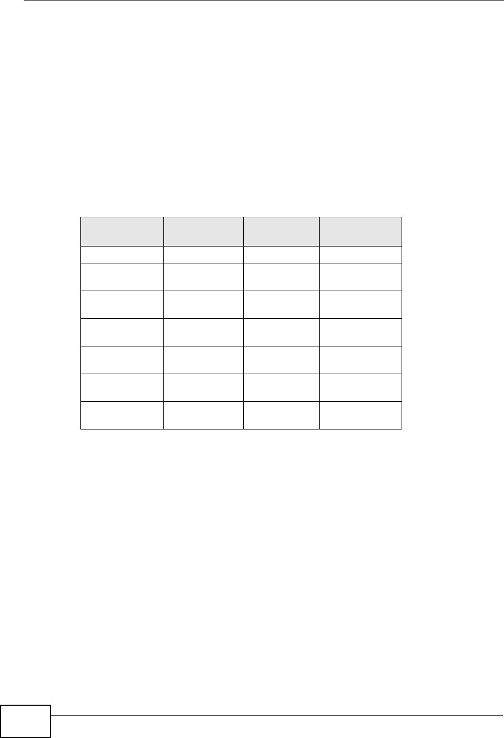
Appendix D IP Addresses and Subnetting
User’s Guide
302
Notation
Since the mask is always a continuous number of ones beginning from the left,
followed by a continuous number of zeros for the remainder of the 32 bit mask,
you can simply specify the number of ones instead of writing the value of each
octet. This is usually specified by writing a “/” followed by the number of bits in
the mask after the address.
For example, 192.1.1.0 /25 is equivalent to saying 192.1.1.0 with subnet mask
255.255.255.128.
The following table shows some possible subnet masks using both notations.
Subnetting
You can use subnetting to divide one network into multiple sub-networks. In the
following example a network administrator creates two sub-networks to isolate a
group of servers from the rest of the company network for security reasons.
In this example, the company network address is 192.168.1.0. The first three
octets of the address (192.168.1) are the network number, and the remaining
octet is the host ID, allowing a maximum of 28 – 2 or 254 possible hosts.
Table 117 Alternative Subnet Mask Notation
SUBNET
MASK ALTERNATIVE
NOTATION LAST OCTET
(BINARY) LAST OCTET
(DECIMAL)
255.255.255.0 /24 0000 0000 0
255.255.255.12
8/25 1000 0000 128
255.255.255.19
2/26 1100 0000 192
255.255.255.22
4/27 1110 0000 224
255.255.255.24
0/28 1111 0000 240
255.255.255.24
8/29 1111 1000 248
255.255.255.25
2/30 1111 1100 252
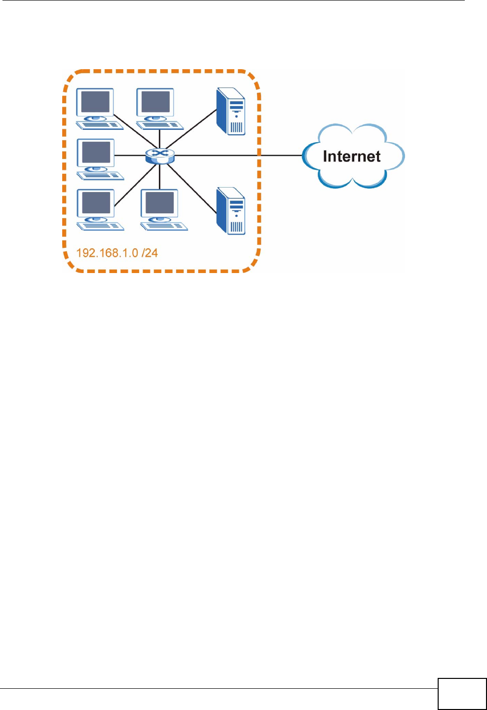
Appendix D IP Addresses and Subnetting
User’s Guide 303
The following figure shows the company network before subnetting.
Figure 145 Subnetting Example: Before Subnetting
You can “borrow” one of the host ID bits to divide the network 192.168.1.0 into
two separate sub-networks. The subnet mask is now 25 bits (255.255.255.128 or
/25).
The “borrowed” host ID bit can have a value of either 0 or 1, allowing two
subnets; 192.168.1.0 /25 and 192.168.1.128 /25.
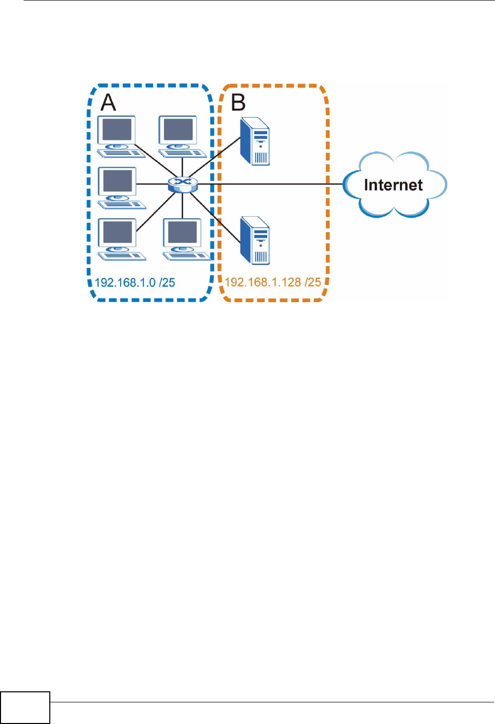
Appendix D IP Addresses and Subnetting
User’s Guide
304
The following figure shows the company network after subnetting. There are now
two sub-networks, A and B.
Figure 146 Subnetting Example: After Subnetting
In a 25-bit subnet the host ID has 7 bits, so each sub-network has a maximum of
27 – 2 or 126 possible hosts (a host ID of all zeroes is the subnet’s address itself,
all ones is the subnet’s broadcast address).
192.168.1.0 with mask 255.255.255.128 is subnet A itself, and 192.168.1.127
with mask 255.255.255.128 is its broadcast address. Therefore, the lowest IP
address that can be assigned to an actual host for subnet A is 192.168.1.1 and
the highest is 192.168.1.126.
Similarly, the host ID range for subnet B is 192.168.1.129 to 192.168.1.254.
Example: Four Subnets
The previous example illustrated using a 25-bit subnet mask to divide a 24-bit
address into two subnets. Similarly, to divide a 24-bit address into four subnets,
you need to “borrow” two host ID bits to give four possible combinations (00, 01,
10 and 11). The subnet mask is 26 bits
(11111111.11111111.11111111.11000000) or 255.255.255.192.
Appendix D IP Addresses and Subnetting
User’s Guide 305
Each subnet contains 6 host ID bits, giving 26 - 2 or 62 hosts for each subnet (a
host ID of all zeroes is the subnet itself, all ones is the subnet’s broadcast
address).
Table 118 Subnet 1
IP/SUBNET MASK NETWORK NUMBER LAST OCTET BIT
VALUE
IP Address (Decimal) 192.168.1. 0
IP Address (Binary) 11000000.10101000.00000001. 00000000
Subnet Mask (Binary) 11111111.11111111.11111111. 11000000
Subnet Address:
192.168.1.0 Lowest Host ID: 192.168.1.1
Broadcast Address:
192.168.1.63 Highest Host ID: 192.168.1.62
Table 119 Subnet 2
IP/SUBNET MASK NETWORK NUMBER LAST OCTET BIT
VALUE
IP Address 192.168.1. 64
IP Address (Binary) 11000000.10101000.00000001. 01000000
Subnet Mask (Binary) 11111111.11111111.11111111. 11000000
Subnet Address:
192.168.1.64 Lowest Host ID: 192.168.1.65
Broadcast Address:
192.168.1.127 Highest Host ID: 192.168.1.126
Table 120 Subnet 3
IP/SUBNET MASK NETWORK NUMBER LAST OCTET BIT
VALUE
IP Address 192.168.1. 128
IP Address (Binary) 11000000.10101000.00000001. 10000000
Subnet Mask (Binary) 11111111.11111111.11111111. 11000000
Subnet Address:
192.168.1.128 Lowest Host ID: 192.168.1.129
Broadcast Address:
192.168.1.191 Highest Host ID: 192.168.1.190
Table 121 Subnet 4
IP/SUBNET MASK NETWORK NUMBER LAST OCTET BIT
VALUE
IP Address 192.168.1. 192
IP Address (Binary) 11000000.10101000.00000001
. 11000000
Subnet Mask (Binary) 11111111.11111111.11111111
. 11000000
Appendix D IP Addresses and Subnetting
User’s Guide
306
Example: Eight Subnets
Similarly, use a 27-bit mask to create eight subnets (000, 001, 010, 011, 100,
101, 110 and 111).
The following table shows IP address last octet values for each subnet.
Subnet Planning
The following table is a summary for subnet planning on a network with a 24-bit
network number.
Subnet Address:
192.168.1.192 Lowest Host ID: 192.168.1.193
Broadcast Address:
192.168.1.255 Highest Host ID: 192.168.1.254
Table 121 Subnet 4 (continued)
IP/SUBNET MASK NETWORK NUMBER LAST OCTET BIT
VALUE
Table 122 Eight Subnets
SUBNET SUBNET
ADDRESS FIRST ADDRESS LAST
ADDRESS BROADCAST
ADDRESS
1 0 1 30 31
232 33 62 63
364 65 94 95
496 97 126 127
5128 129 158 159
6160 161 190 191
7192 193 222 223
8224 225 254 255
Table 123 24-bit Network Number Subnet Planning
NO. “BORROWED”
HOST BITS SUBNET MASK NO. SUBNETS NO. HOSTS PER
SUBNET
1255.255.255.128 (/25) 2126
2255.255.255.192 (/26) 462
3255.255.255.224 (/27) 830
4255.255.255.240 (/28) 16 14
5255.255.255.248 (/29) 32 6
6255.255.255.252 (/30) 64 2
7255.255.255.254 (/31) 128 1
Appendix D IP Addresses and Subnetting
User’s Guide 307
The following table is a summary for subnet planning on a network with a 16-bit
network number.
Configuring IP Addresses
Where you obtain your network number depends on your particular situation. If
the ISP or your network administrator assigns you a block of registered IP
addresses, follow their instructions in selecting the IP addresses and the subnet
mask.
If the ISP did not explicitly give you an IP network number, then most likely you
have a single user account and the ISP will assign you a dynamic IP address when
the connection is established. If this is the case, it is recommended that you select
a network number from 192.168.0.0 to 192.168.255.0. The Internet Assigned
Number Authority (IANA) reserved this block of addresses specifically for private
use; please do not use any other number unless you are told otherwise. You must
also enable Network Address Translation (NAT) on the WiMAX Modem.
Once you have decided on the network number, pick an IP address for your
WiMAX Modem that is easy to remember (for instance, 192.168.1.1) but make
sure that no other device on your network is using that IP address.
The subnet mask specifies the network number portion of an IP address. Your
WiMAX Modem will compute the subnet mask automatically based on the IP
Table 124 16-bit Network Number Subnet Planning
NO. “BORROWED”
HOST BITS SUBNET MASK NO.
SUBNETS NO. HOSTS PER
SUBNET
1255.255.128.0 (/17) 232766
2255.255.192.0 (/18) 416382
3255.255.224.0 (/19) 88190
4255.255.240.0 (/20) 16 4094
5255.255.248.0 (/21) 32 2046
6255.255.252.0 (/22) 64 1022
7255.255.254.0 (/23) 128 510
8255.255.255.0 (/24) 256 254
9255.255.255.128 (/25) 512 126
10 255.255.255.192 (/26) 1024 62
11 255.255.255.224 (/27) 2048 30
12 255.255.255.240 (/28) 4096 14
13 255.255.255.248 (/29) 8192 6
14 255.255.255.252 (/30) 16384 2
15 255.255.255.254 (/31) 32768 1

Appendix D IP Addresses and Subnetting
User’s Guide
308
address that you entered. You don't need to change the subnet mask computed
by the WiMAX Modem unless you are instructed to do otherwise.
Private IP Addresses
Every machine on the Internet must have a unique address. If your networks are
isolated from the Internet (running only between two branch offices, for example)
you can assign any IP addresses to the hosts without problems. However, the
Internet Assigned Numbers Authority (IANA) has reserved the following three
blocks of IP addresses specifically for private networks:
• 10.0.0.0 — 10.255.255.255
• 172.16.0.0 — 172.31.255.255
• 192.168.0.0 — 192.168.255.255
You can obtain your IP address from the IANA, from an ISP, or it can be assigned
from a private network. If you belong to a small organization and your Internet
access is through an ISP, the ISP can provide you with the Internet addresses for
your local networks. On the other hand, if you are part of a much larger
organization, you should consult your network administrator for the appropriate IP
addresses.
Regardless of your particular situation, do not create an arbitrary IP address;
always follow the guidelines above. For more information on address assignment,
please refer to RFC 1597, Address Allocation for Private Internets and RFC 1466,
Guidelines for Management of IP Address Space.
IP Address Conflicts
Each device on a network must have a unique IP address. Devices with duplicate
IP addresses on the same network will not be able to access the Internet or other
resources. The devices may also be unreachable through the network.
Conflicting Computer IP Addresses Example
More than one device can not use the same IP address. In the following example
computer A has a static (or fixed) IP address that is the same as the IP address
that a DHCP server assigns to computer B which is a DHCP client. Neither can
access the Internet. This problem can be solved by assigning a different static IP
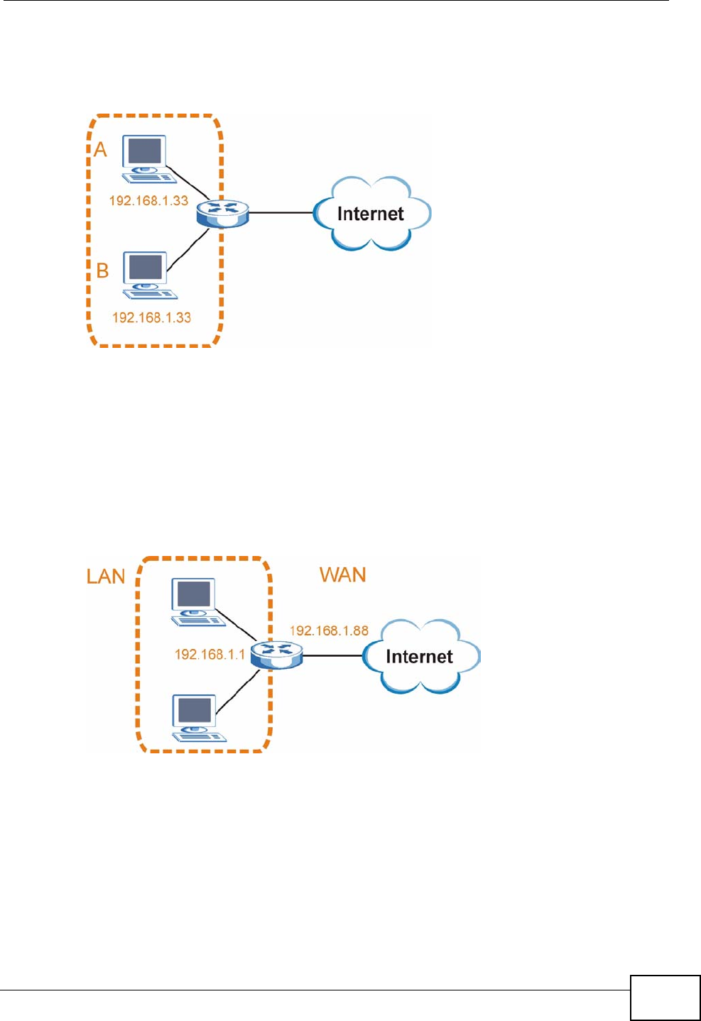
Appendix D IP Addresses and Subnetting
User’s Guide 309
address to computer A or setting computer A to obtain an IP address
automatically.
Figure 147 Conflicting Computer IP Addresses Example
Conflicting Router IP Addresses Example
Since a router connects different networks, it must have interfaces using different
network numbers. For example, if a router is set between a LAN and the Internet
(WAN), the router’s LAN and WAN addresses must be on different subnets. In the
following example, the LAN and WAN are on the same subnet. The LAN computers
cannot access the Internet because the router cannot route between networks.
Figure 148 Conflicting Computer IP Addresses Example
Conflicting Computer and Router IP Addresses Example
More than one device can not use the same IP address. In the following example,
the computer and the router’s LAN port both use 192.168.1.1 as the IP address.
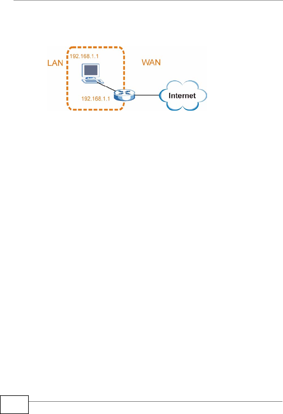
Appendix D IP Addresses and Subnetting
User’s Guide
310
The computer cannot access the Internet. This problem can be solved by
assigning a different IP address to the computer or the router’s LAN port.
Figure 149 Conflicting Computer and Router IP Addresses Example

User’s Guide 311
APPENDIX E
Importing Certificates
This appendix shows you how to import public key certificates into your web
browser.
Public key certificates are used by web browsers to ensure that a secure web site
is legitimate. When a certificate authority such as VeriSign, Comodo, or Network
Solutions, to name a few, receives a certificate request from a website operator,
they confirm that the web domain and contact information in the request match
those on public record with a domain name registrar. If they match, then the
certificate is issued to the website operator, who then places it on the site to be
issued to all visiting web browsers to let them know that the site is legitimate.
Many ZyXEL products, such as the NSA-2401, issue their own public key
certificates. These can be used by web browsers on a LAN or WAN to verify that
they are in fact connecting to the legitimate device and not one masquerading as
it. However, because the certificates were not issued by one of the several
organizations officially recognized by the most common web browsers, you will
need to import the ZyXEL-created certificate into your web browser and flag that
certificate as a trusted authority.
Note: You can see if you are browsing on a secure website if the URL in your web
browser’s address bar begins with https:// or there is a sealed padlock
icon ( ) somewhere in the main browser window (not all browsers show the
padlock in the same location.)
In this appendix, you can import a public key certificate for:
• Internet Explorer on page 312
•Firefox on page 322
•Opera on page 328
• Konqueror on page 336
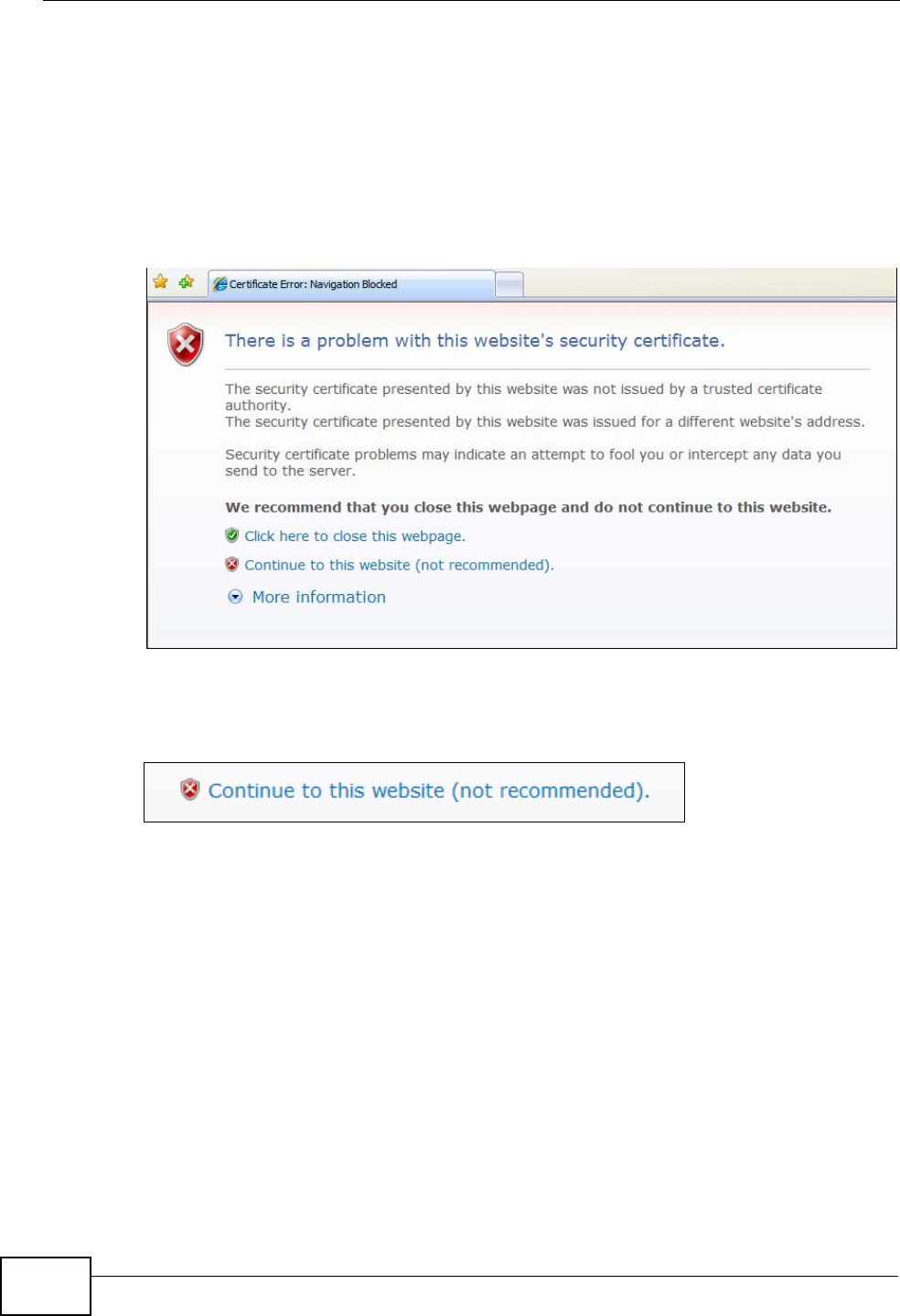
Appendix E Importing Certificates
User’s Guide
312
Internet Explorer
The following example uses Microsoft Internet Explorer 7 on Windows XP
Professional; however, they can also apply to Internet Explorer on Windows Vista.
1If your device’s web configurator is set to use SSL certification, then the first time
you browse to it you are presented with a certification error.
Figure 150 Internet Explorer 7: Certification Error
2Click Continue to this website (not recommended).
Figure 151 Internet Explorer 7: Certification Error
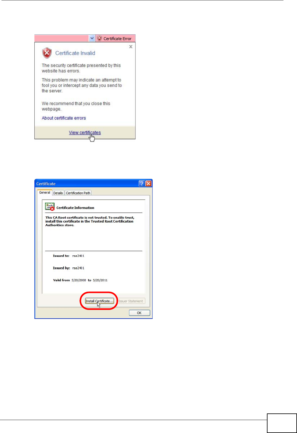
Appendix E Importing Certificates
User’s Guide 313
3In the Address Bar, click Certificate Error > View certificates.
Figure 152 Internet Explorer 7: Certificate Error
4In the Certificate dialog box, click Install Certificate.
Figure 153 Internet Explorer 7: Certificate
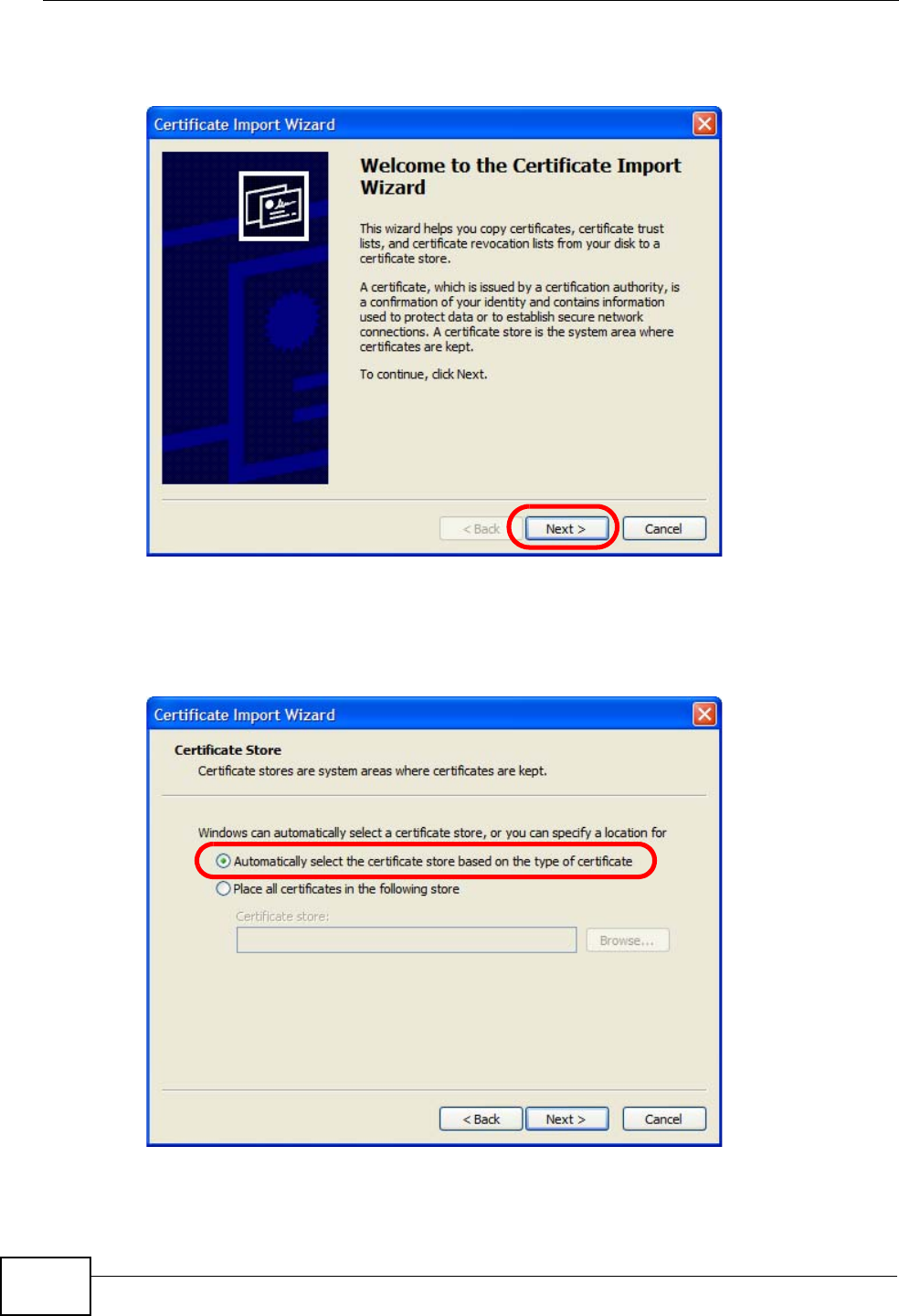
Appendix E Importing Certificates
User’s Guide
314
5In the Certificate Import Wizard, click Next.
Figure 154 Internet Explorer 7: Certificate Import Wizard
6If you want Internet Explorer to Automatically select certificate store based
on the type of certificate, click Next again and then go to step 9.
Figure 155 Internet Explorer 7: Certificate Import Wizard
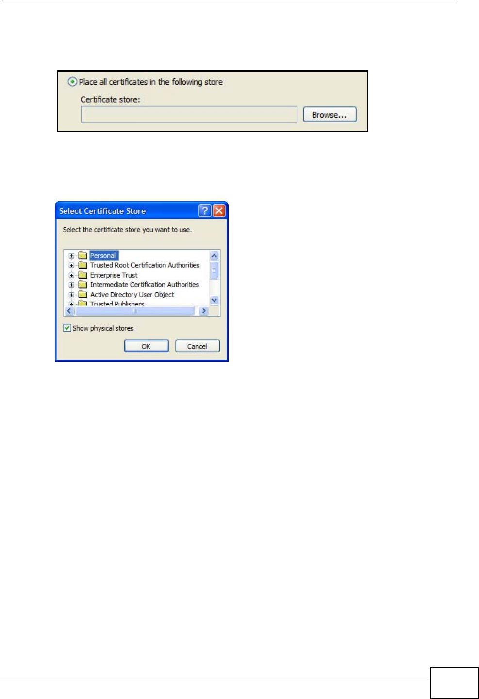
Appendix E Importing Certificates
User’s Guide 315
7Otherwise, select Place all certificates in the following store and then click
Browse.
Figure 156 Internet Explorer 7: Certificate Import Wizard
8In the Select Certificate Store dialog box, choose a location in which to save the
certificate and then click OK.
Figure 157 Internet Explorer 7: Select Certificate Store
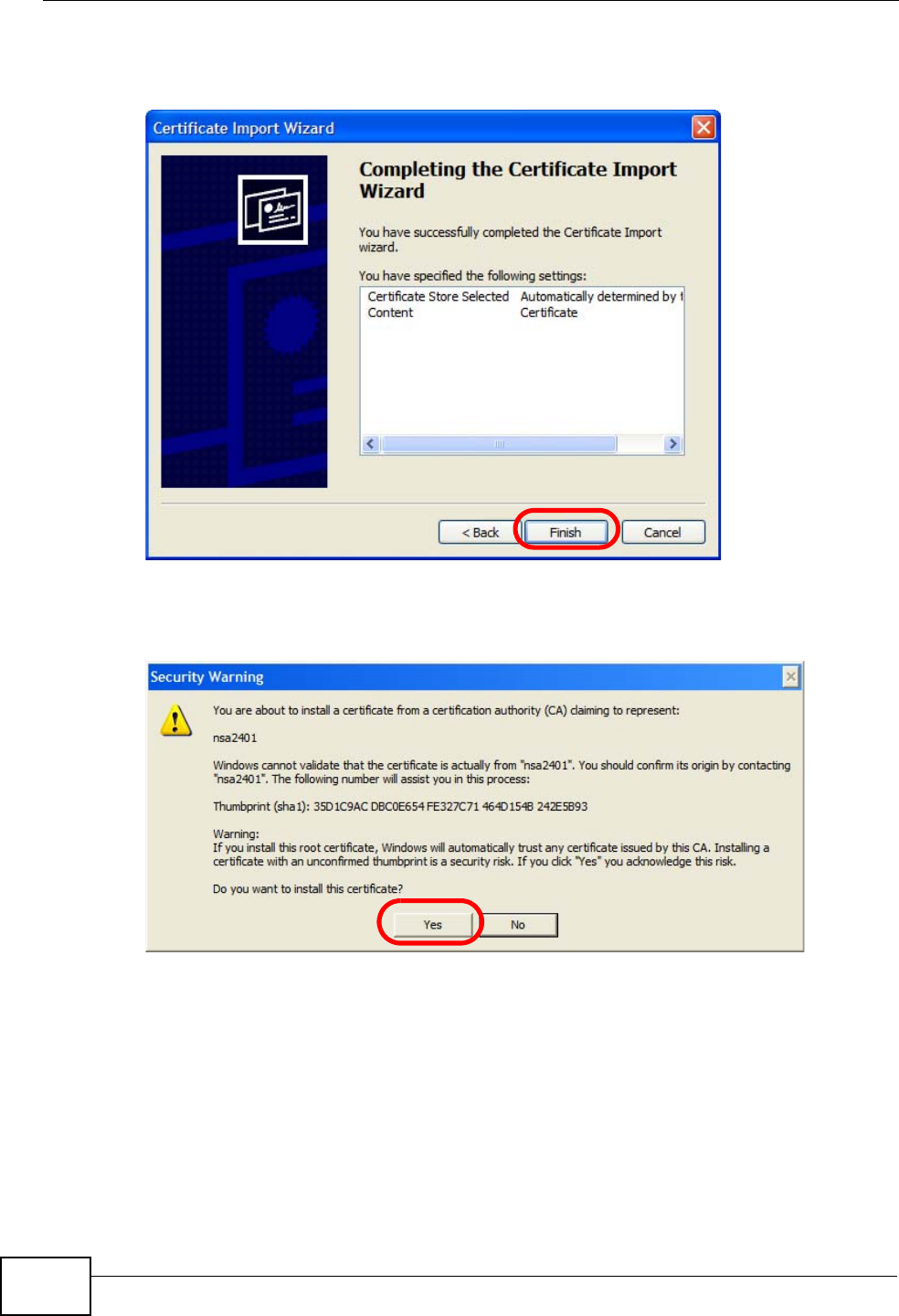
Appendix E Importing Certificates
User’s Guide
316
9In the Completing the Certificate Import Wizard screen, click Finish.
Figure 158 Internet Explorer 7: Certificate Import Wizard
10 If you are presented with another Security Warning, click Yes.
Figure 159 Internet Explorer 7: Security Warning
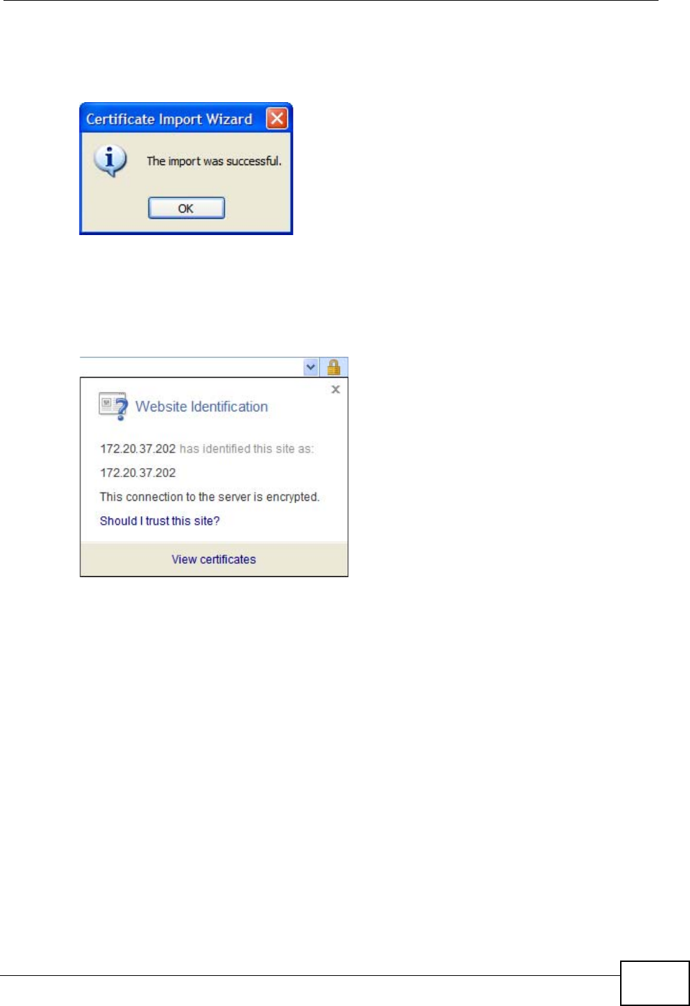
Appendix E Importing Certificates
User’s Guide 317
11 Finally, click OK when presented with the successful certificate installation
message.
Figure 160 Internet Explorer 7: Certificate Import Wizard
12 The next time you start Internet Explorer and go to a ZyXEL web configurator
page, a sealed padlock icon appears in the address bar. Click it to view the page’s
Website Identification information.
Figure 161 Internet Explorer 7: Website Identification
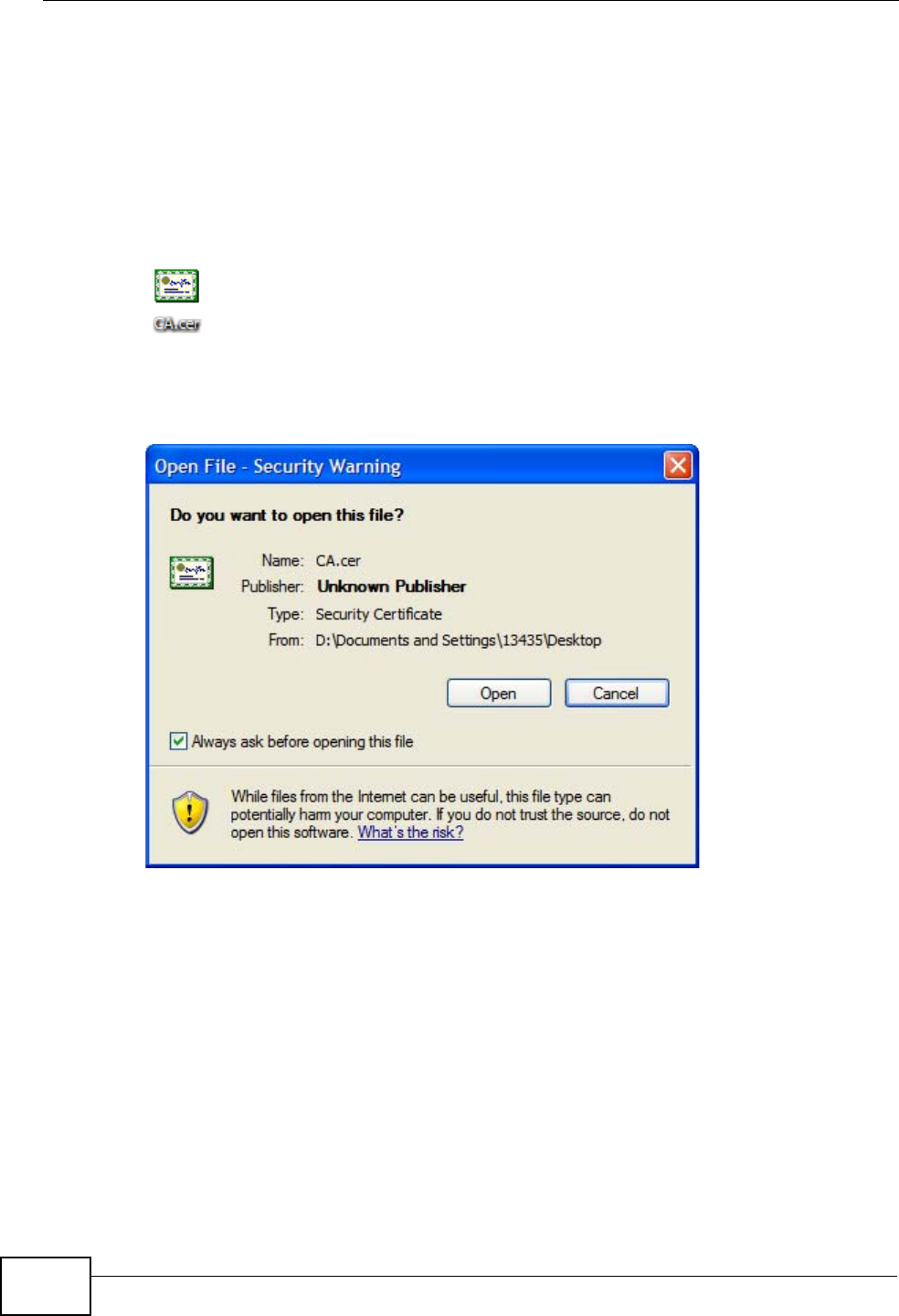
Appendix E Importing Certificates
User’s Guide
318
Installing a Stand-Alone Certificate File in Internet Explorer
Rather than browsing to a ZyXEL web configurator and installing a public key
certificate when prompted, you can install a stand-alone certificate file if one has
been issued to you.
1Double-click the public key certificate file.
Figure 162 Internet Explorer 7: Public Key Certificate File
2In the security warning dialog box, click Open.
Figure 163 Internet Explorer 7: Open File - Security Warning
3Refer to steps 4-12 in the Internet Explorer procedure beginning on page 312 to
complete the installation process.
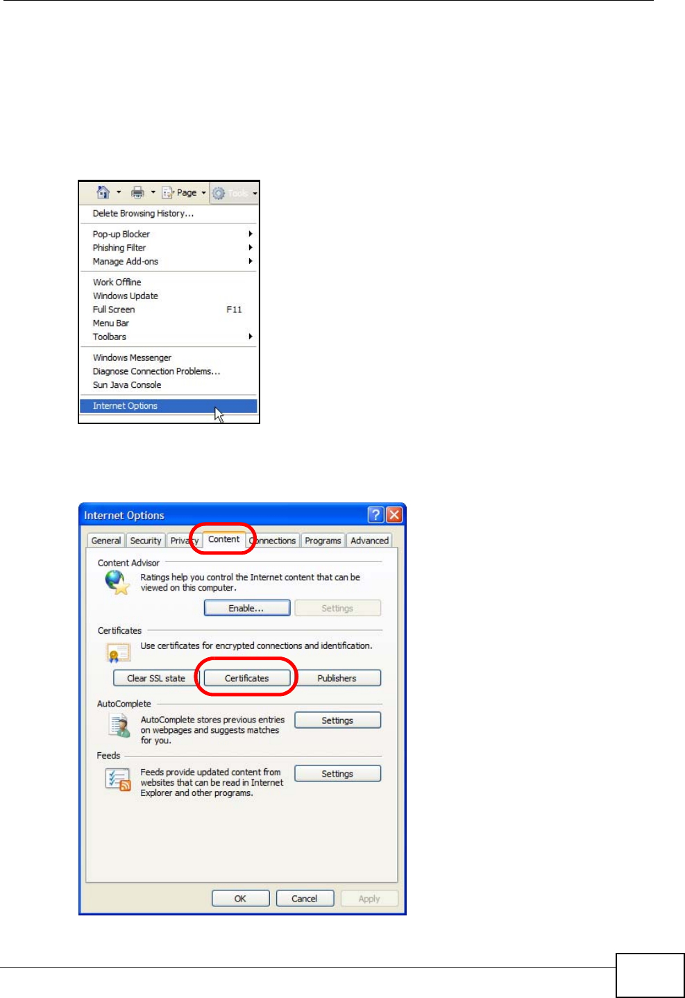
Appendix E Importing Certificates
User’s Guide 319
Removing a Certificate in Internet Explorer
This section shows you how to remove a public key certificate in Internet Explorer
7.
1Open Internet Explorer and click TOOLS > Internet Options.
Figure 164 Internet Explorer 7: Tools Menu
2In the Internet Options dialog box, click Content > Certificates.
Figure 165 Internet Explorer 7: Internet Options
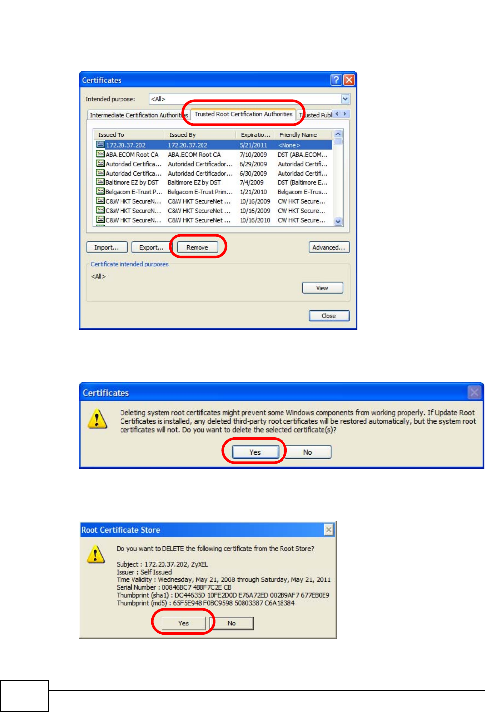
Appendix E Importing Certificates
User’s Guide
320
3In the Certificates dialog box, click the Trusted Root Certificates Authorities
tab, select the certificate that you want to delete, and then click Remove.
Figure 166 Internet Explorer 7: Certificates
4In the Certificates confirmation, click Yes.
Figure 167 Internet Explorer 7: Certificates
5In the Root Certificate Store dialog box, click Yes.
Figure 168 Internet Explorer 7: Root Certificate Store

Appendix E Importing Certificates
User’s Guide 321
6The next time you go to the web site that issued the public key certificate you just
removed, a certification error appears.
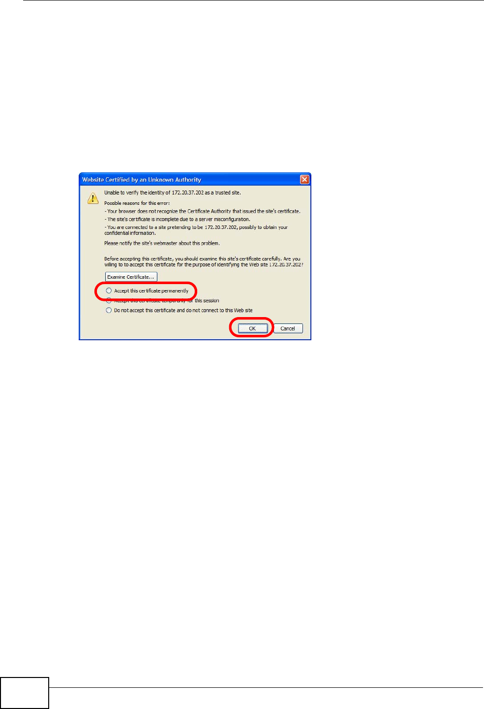
Appendix E Importing Certificates
User’s Guide
322
Firefox
The following example uses Mozilla Firefox 2 on Windows XP Professional;
however, the screens can also apply to Firefox 2 on all platforms.
1If your device’s web configurator is set to use SSL certification, then the first time
you browse to it you are presented with a certification error.
2Select Accept this certificate permanently and click OK.
Figure 169 Firefox 2: Website Certified by an Unknown Authority
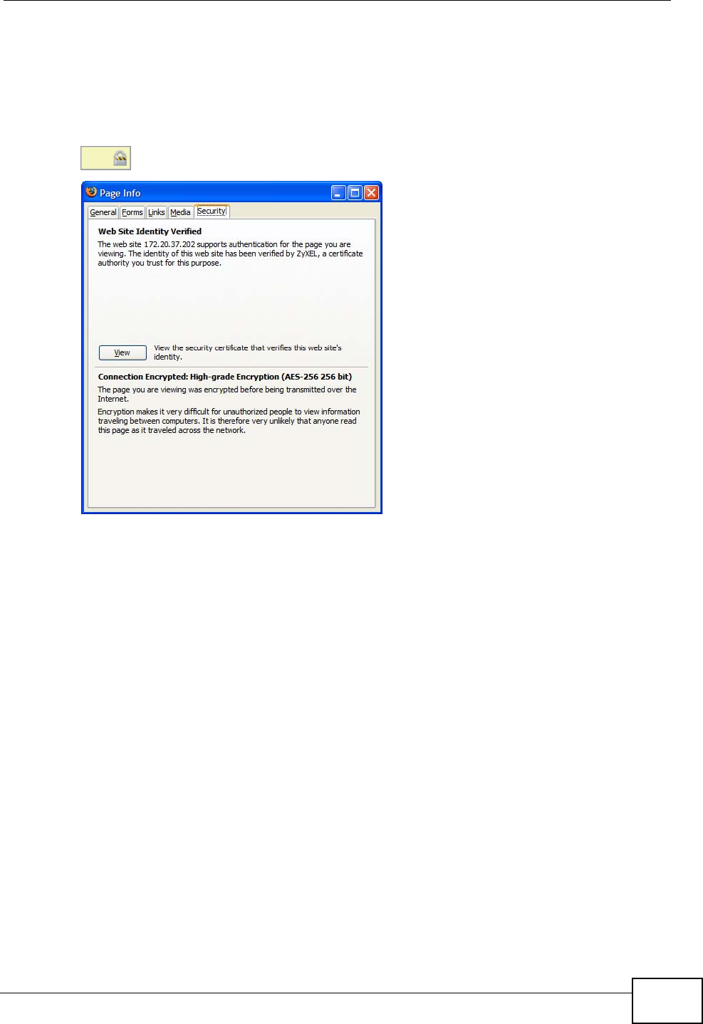
Appendix E Importing Certificates
User’s Guide 323
3The certificate is stored and you can now connect securely to the web
configurator. A sealed padlock appears in the address bar, which you can click to
open the Page Info > Security window to view the web page’s security
information.
Figure 170 Firefox 2: Page Info
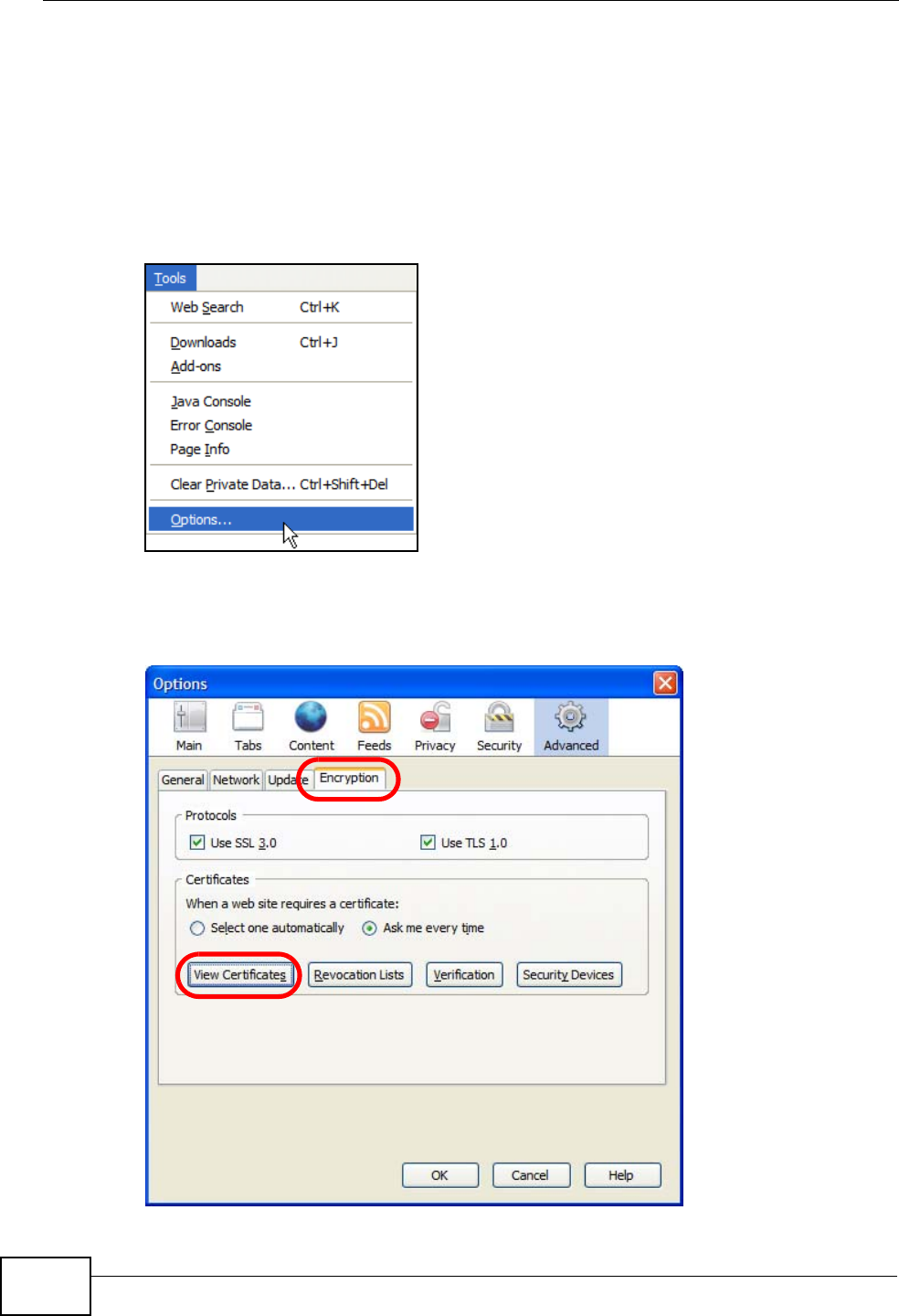
Appendix E Importing Certificates
User’s Guide
324
Installing a Stand-Alone Certificate File in Firefox
Rather than browsing to a ZyXEL web configurator and installing a public key
certificate when prompted, you can install a stand-alone certificate file if one has
been issued to you.
1Open Firefox and click TOOLS > Options.
Figure 171 Firefox 2: Tools Menu
2In the Options dialog box, click ADVANCED > Encryption > View Certificates.
Figure 172 Firefox 2: Options
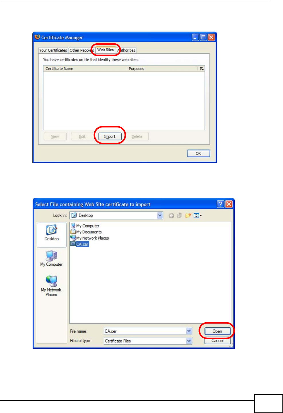
Appendix E Importing Certificates
User’s Guide 325
3In the Certificate Manager dialog box, click Web Sites > Import.
Figure 173 Firefox 2: Certificate Manager
4Use the Select File dialog box to locate the certificate and then click Open.
Figure 174 Firefox 2: Select File
5The next time you visit the web site, click the padlock in the address bar to open
the Page Info > Security window to see the web page’s security information.
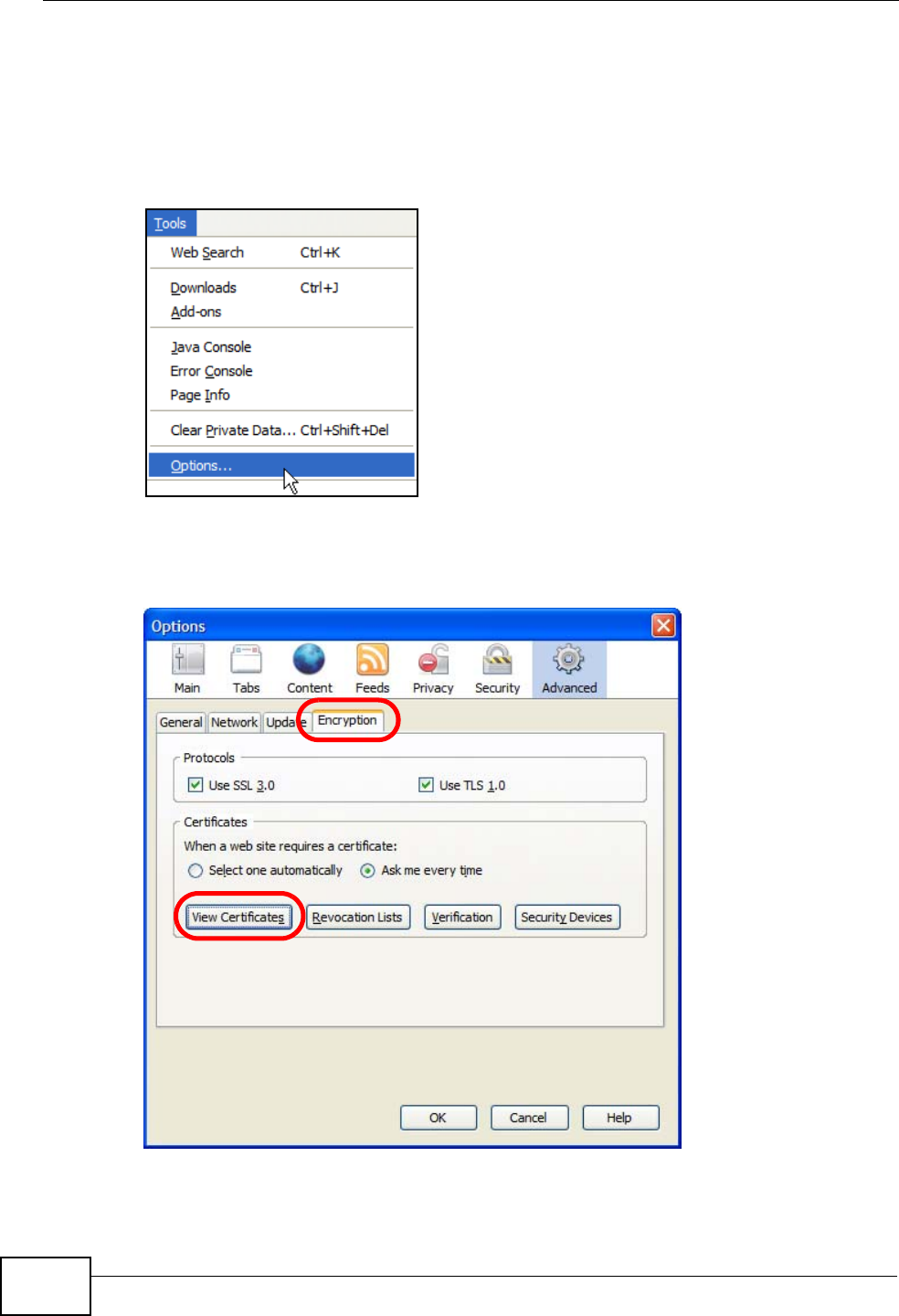
Appendix E Importing Certificates
User’s Guide
326
Removing a Certificate in Firefox
This section shows you how to remove a public key certificate in Firefox 2.
1Open Firefox and click TOOLS > Options.
Figure 175 Firefox 2: Tools Menu
2In the Options dialog box, click ADVANCED > Encryption > View Certificates.
Figure 176 Firefox 2: Options
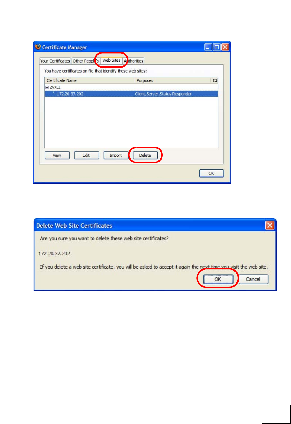
Appendix E Importing Certificates
User’s Guide 327
3In the Certificate Manager dialog box, select the Web Sites tab, select the
certificate that you want to remove, and then click Delete.
Figure 177 Firefox 2: Certificate Manager
4In the Delete Web Site Certificates dialog box, click OK.
Figure 178 Firefox 2: Delete Web Site Certificates
5The next time you go to the web site that issued the public key certificate you just
removed, a certification error appears.
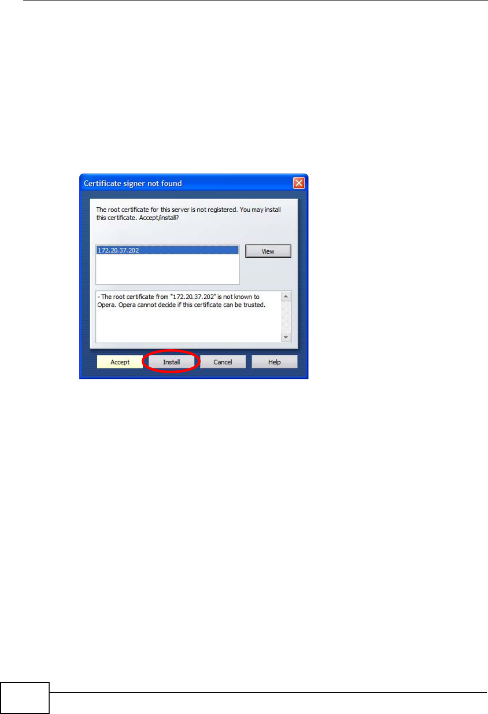
Appendix E Importing Certificates
User’s Guide
328
Opera
The following example uses Opera 9 on Windows XP Professional; however, the
screens can apply to Opera 9 on all platforms.
1If your device’s web configurator is set to use SSL certification, then the first time
you browse to it you are presented with a certification error.
2Click Install to accept the certificate.
Figure 179 Opera 9: Certificate signer not found
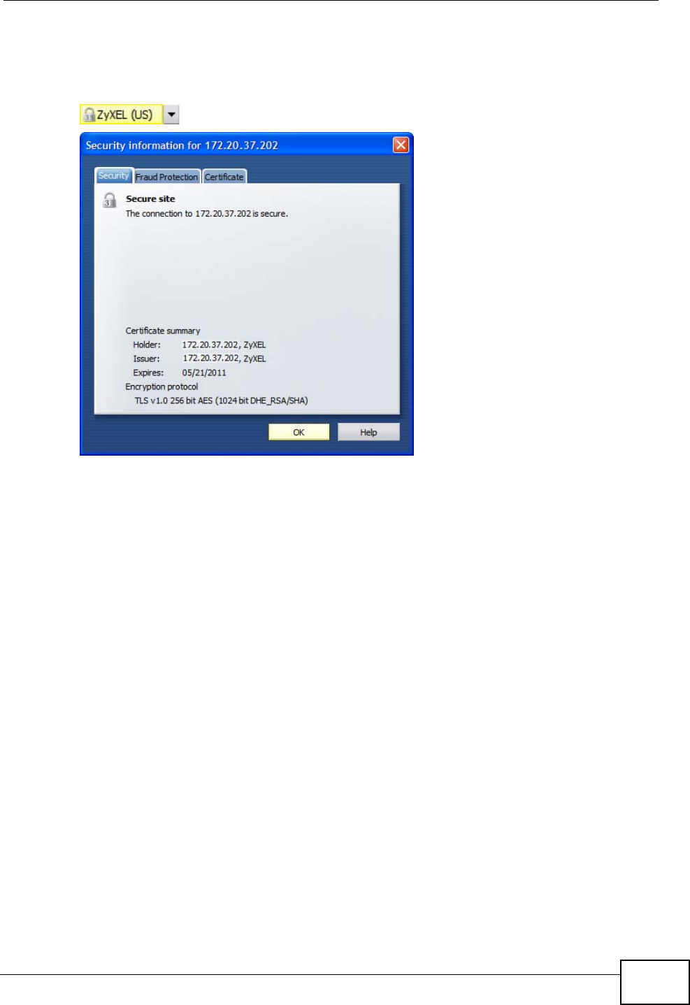
Appendix E Importing Certificates
User’s Guide 329
3The next time you visit the web site, click the padlock in the address bar to open
the Security information window to view the web page’s security details.
Figure 180 Opera 9: Security information
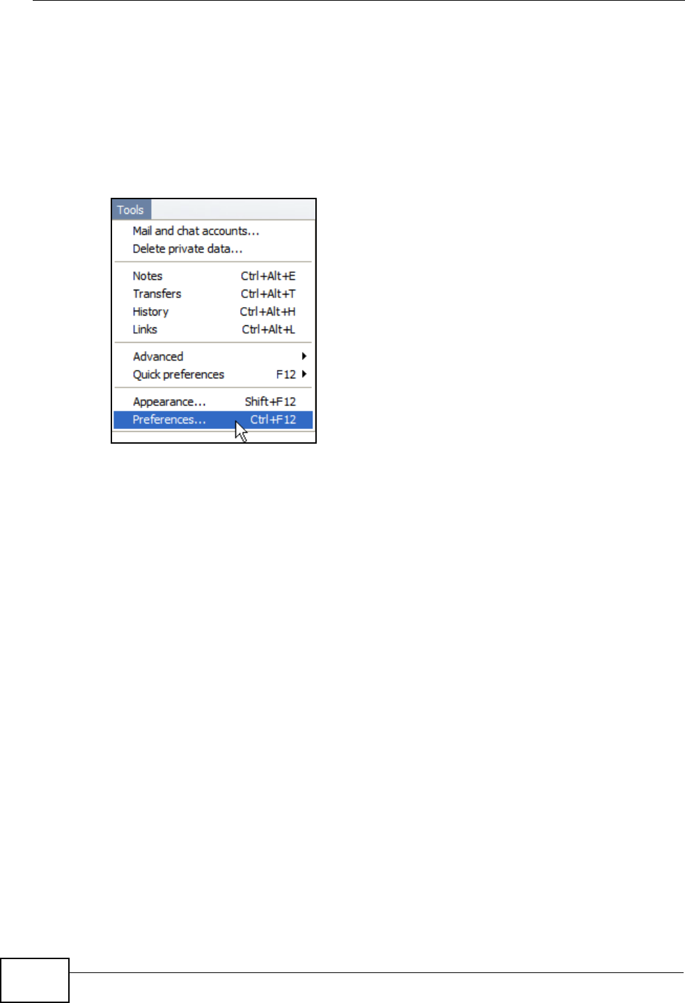
Appendix E Importing Certificates
User’s Guide
330
Installing a Stand-Alone Certificate File in Opera
Rather than browsing to a ZyXEL web configurator and installing a public key
certificate when prompted, you can install a stand-alone certificate file if one has
been issued to you.
1Open Opera and click TOOLS > Preferences.
Figure 181 Opera 9: Tools Menu
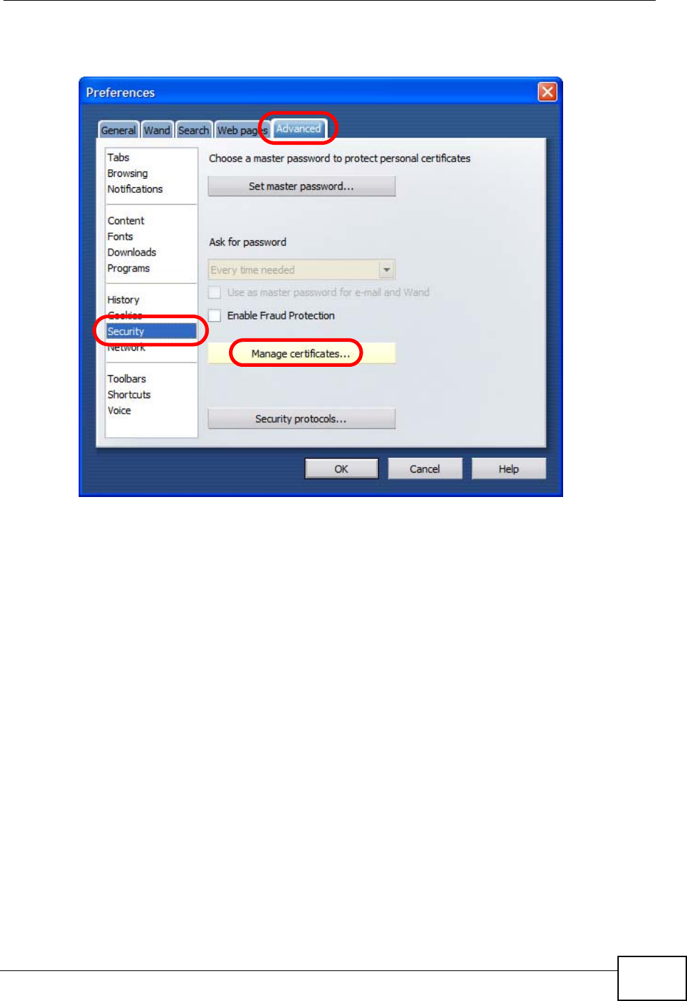
Appendix E Importing Certificates
User’s Guide 331
2In Preferences, click ADVANCED > Security > Manage certificates.
Figure 182 Opera 9: Preferences
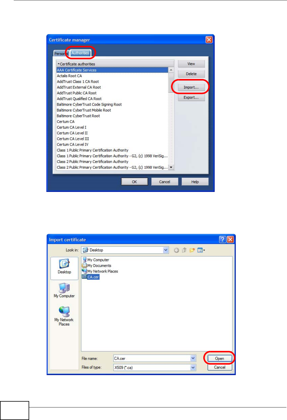
Appendix E Importing Certificates
User’s Guide
332
3In the Certificates Manager, click Authorities > Import.
Figure 183 Opera 9: Certificate manager
4Use the Import certificate dialog box to locate the certificate and then click
Open.
Figure 184 Opera 9: Import certificate
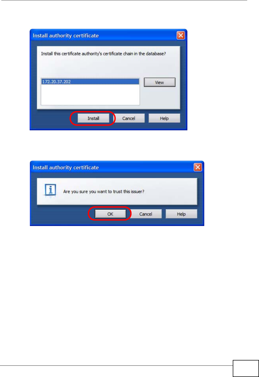
Appendix E Importing Certificates
User’s Guide 333
5In the Install authority certificate dialog box, click Install.
Figure 185 Opera 9: Install authority certificate
6Next, click OK.
Figure 186 Opera 9: Install authority certificate
7The next time you visit the web site, click the padlock in the address bar to open
the Security information window to view the web page’s security details.
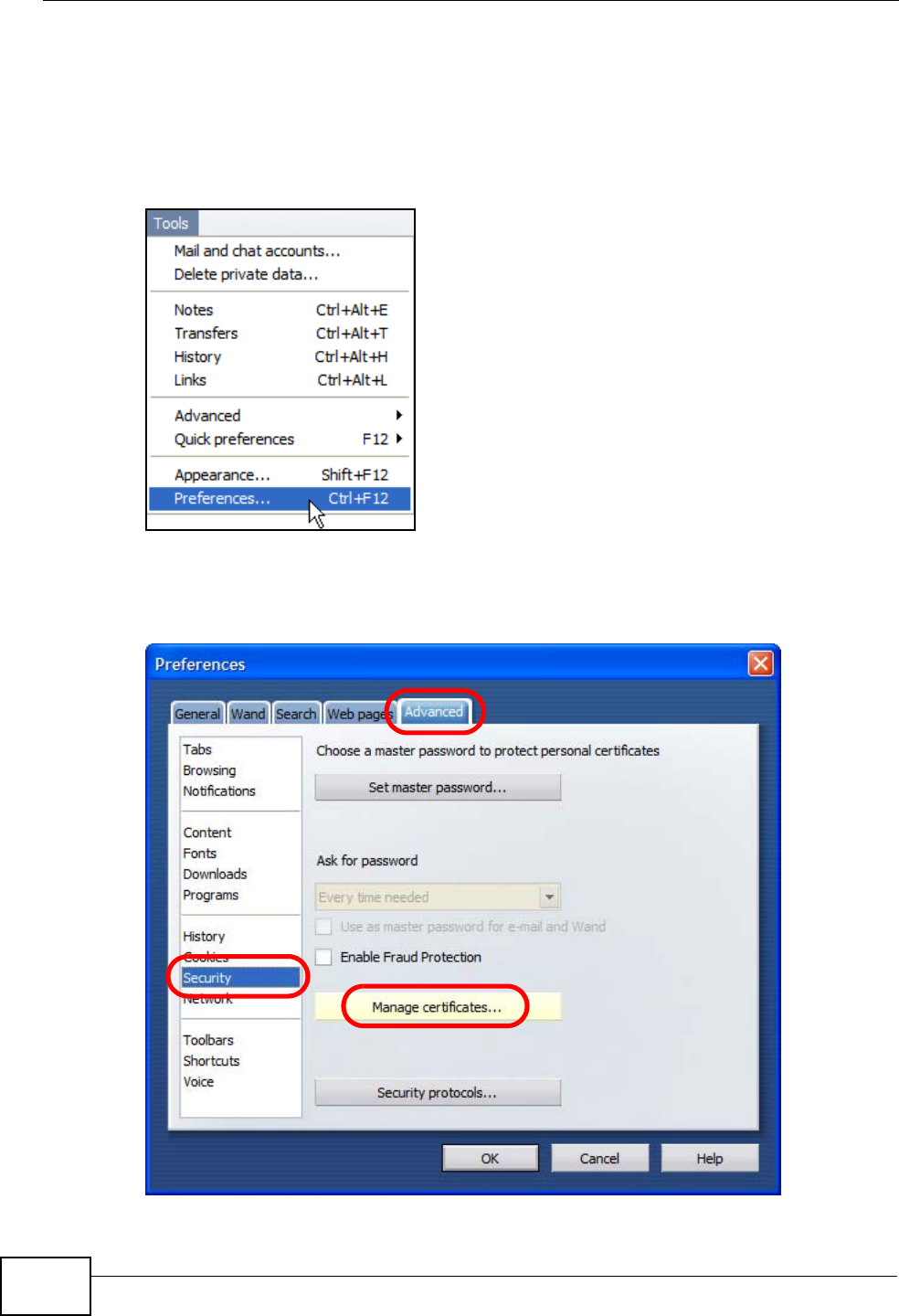
Appendix E Importing Certificates
User’s Guide
334
Removing a Certificate in Opera
This section shows you how to remove a public key certificate in Opera 9.
1Open Opera and click TOOLS > Preferences.
Figure 187 Opera 9: Tools Menu
2In Preferences, ADVANCED > Security > Manage certificates.
Figure 188 Opera 9: Preferences
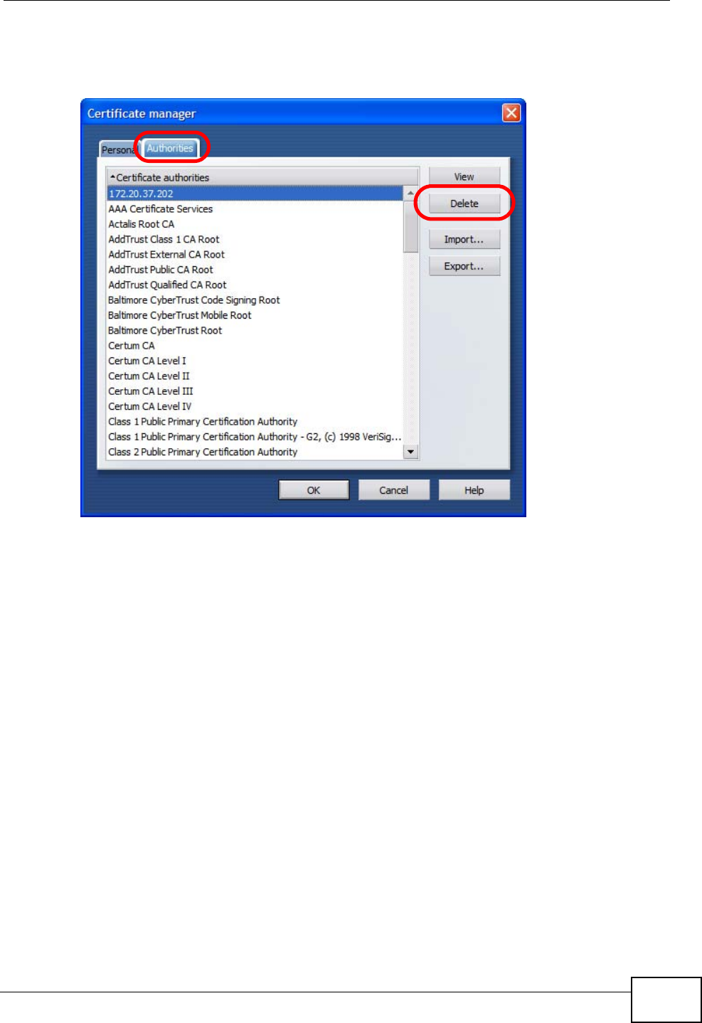
Appendix E Importing Certificates
User’s Guide 335
3In the Certificates manager, select the Authorities tab, select the certificate
that you want to remove, and then click Delete.
Figure 189 Opera 9: Certificate manager
4The next time you go to the web site that issued the public key certificate you just
removed, a certification error appears.
Note: There is no confirmation when you delete a certificate authority, so be
absolutely certain that you want to go through with it before clicking the button.
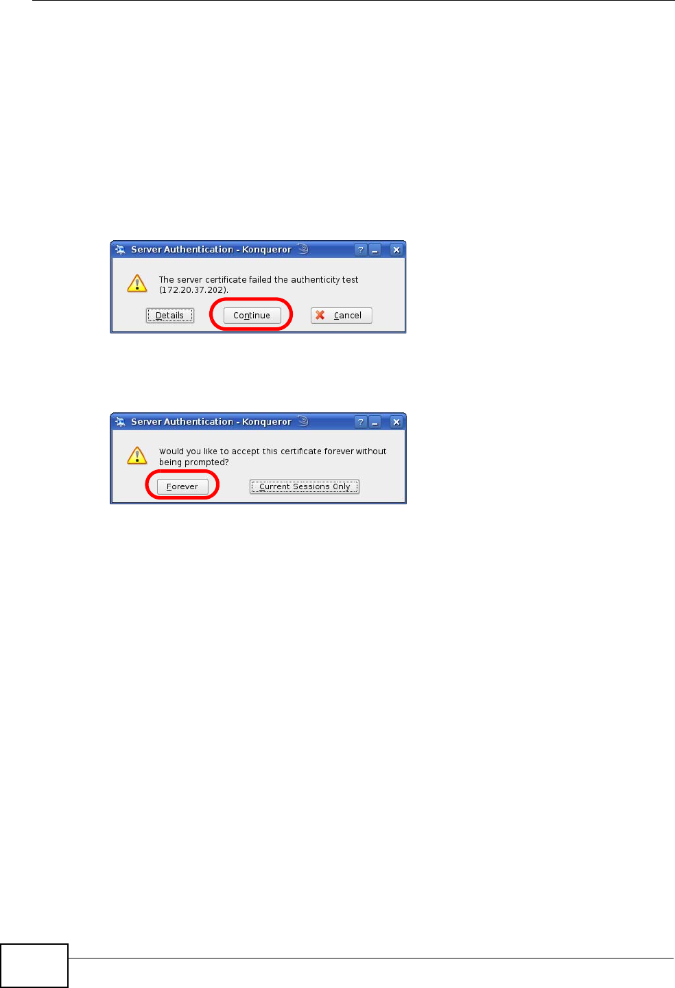
Appendix E Importing Certificates
User’s Guide
336
Konqueror
The following example uses Konqueror 3.5 on openSUSE 10.3, however the
screens apply to Konqueror 3.5 on all Linux KDE distributions.
1If your device’s web configurator is set to use SSL certification, then the first time
you browse to it you are presented with a certification error.
2Click Continue.
Figure 190 Konqueror 3.5: Server Authentication
3Click Forever when prompted to accept the certificate.
Figure 191 Konqueror 3.5: Server Authentication
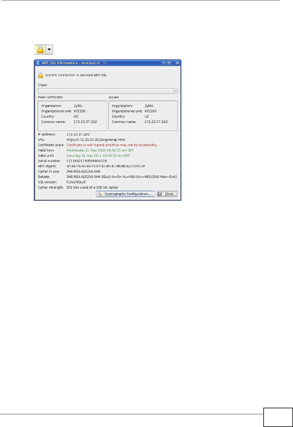
Appendix E Importing Certificates
User’s Guide 337
4Click the padlock in the address bar to open the KDE SSL Information window
and view the web page’s security details.
Figure 192 Konqueror 3.5: KDE SSL Information
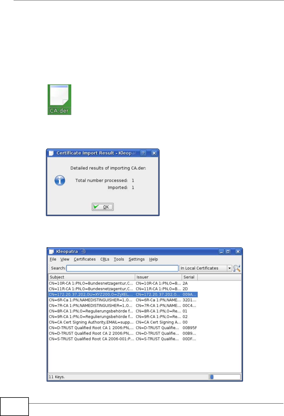
Appendix E Importing Certificates
User’s Guide
338
Installing a Stand-Alone Certificate File in Konqueror
Rather than browsing to a ZyXEL web configurator and installing a public key
certificate when prompted, you can install a stand-alone certificate file if one has
been issued to you.
1Double-click the public key certificate file.
Figure 193 Konqueror 3.5: Public Key Certificate File
2In the Certificate Import Result - Kleopatra dialog box, click OK.
Figure 194 Konqueror 3.5: Certificate Import Result
The public key certificate appears in the KDE certificate manager, Kleopatra.
Figure 195 Konqueror 3.5: Kleopatra

Appendix E Importing Certificates
User’s Guide 339
3The next time you visit the web site, click the padlock in the address bar to open
the KDE SSL Information window to view the web page’s security details.
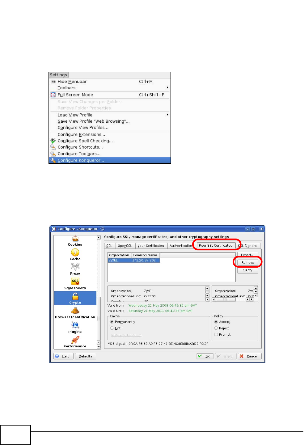
Appendix E Importing Certificates
User’s Guide
340
Removing a Certificate in Konqueror
This section shows you how to remove a public key certificate in Konqueror 3.5.
1Open Konqueror and click Settings > Configure Konqueror.
Figure 196 Konqueror 3.5: Settings Menu
2In the Configure dialog box, select Crypto.
3On the Peer SSL Certificates tab, select the certificate you want to delete and
then click Remove.
Figure 197 Konqueror 3.5: Configure
4The next time you go to the web site that issued the public key certificate you just
removed, a certification error appears.

Appendix E Importing Certificates
User’s Guide 341
Note: There is no confirmation when you remove a certificate authority, so be
absolutely certain you want to go through with it before clicking the button.

Appendix E Importing Certificates
User’s Guide
342

User’s Guide 343
APPENDIX F
SIP Passthrough
Enabling/Disabling the SIP ALG
You can turn off the WiMAX Modem SIP ALG to avoid retranslating the IP address
of an existing SIP device that is using STUN. If you want to use STUN with a SIP
client device (a SIP phone or IP phone for example) behind the WiMAX Modem,
use the ip alg disable ALG_SIP command to turn off the SIP ALG.
Signaling Session Timeout
Most SIP clients have an “expire” mechanism indicating the lifetime of signaling
sessions. The SIP UA sends registration packets to the SIP server periodically and
keeps the session alive in the WiMAX Modem.
If the SIP client does not have this mechanism and makes no call during the
WiMAX Modem SIP timeout default (60 minutes), the WiMAX Modem SIP ALG
drops any incoming calls after the timeout period. You can use the ip alg
siptimeout command to change the timeout value.
Audio Session Timeout
If no voice packets go through the SIP ALG before the timeout period default (5
minutes) expires, the SIP ALG does not drop the call but blocks all voice traffic
and deletes the audio session. You cannot hear anything and you will need to
make a new call to continue your conversation.

Appendix F SIP Passthrough
User’s Guide
344

User’s Guide 345
APPENDIX G
Common Services
The following table lists some commonly-used services and their associated
protocols and port numbers. For a comprehensive list of port numbers, ICMP type/
code numbers and services, visit the IANA (Internet Assigned Number Authority)
web site.
•Name: This is a short, descriptive name for the service. You can use this one or
create a different one, if you like.
•Protocol: This is the type of IP protocol used by the service. If this is TCP/
UDP, then the service uses the same port number with TCP and UDP. If this is
USER-DEFINED, the Port(s) is the IP protocol number, not the port number.
•Port(s): This value depends on the Protocol. Please refer to RFC 1700 for
further information about port numbers.
•If the Protocol is TCP, UDP, or TCP/UDP, this is the IP port number.
•If the Protocol is USER, this is the IP protocol number.
•Description: This is a brief explanation of the applications that use this service
or the situations in which this service is used.
Table 125 Commonly Used Services
NAME PROTOCOL PORT(S) DESCRIPTION
AH
(IPSEC_TUNNEL) User-Defined 51 The IPSEC AH (Authentication
Header) tunneling protocol uses this
service.
AIM/New-ICQ TCP 5190 AOL’s Internet Messenger service. It
is also used as a listening port by
ICQ.
AUTH TCP 113 Authentication protocol used by some
servers.
BGP TCP 179 Border Gateway Protocol.
BOOTP_CLIENT UDP 68 DHCP Client.
BOOTP_SERVER UDP 67 DHCP Server.
CU-SEEME TCP
UDP
7648
24032
A popular videoconferencing solution
from White Pines Software.
DNS TCP/UDP 53 Domain Name Server, a service that
matches web names (for example
www.zyxel.com) to IP numbers.

Appendix G Common Services
User’s Guide
346
ESP
(IPSEC_TUNNEL) User-Defined 50 The IPSEC ESP (Encapsulation
Security Protocol) tunneling protocol
uses this service.
FINGER TCP 79 Finger is a UNIX or Internet related
command that can be used to find out
if a user is logged on.
FTP TCP
TCP
20
21
File Transfer Program, a program to
enable fast transfer of files, including
large files that may not be possible by
e-mail.
H.323 TCP 1720 NetMeeting uses this protocol.
HTTP TCP 80 Hyper Text Transfer Protocol - a
client/server protocol for the world
wide web.
HTTPS TCP 443 HTTPS is a secured http session often
used in e-commerce.
ICMP User-Defined 1Internet Control Message Protocol is
often used for diagnostic or routing
purposes.
ICQ UDP 4000 This is a popular Internet chat
program.
IGMP
(MULTICAST) User-Defined 2Internet Group Management Protocol
is used when sending packets to a
specific group of hosts.
IKE UDP 500 The Internet Key Exchange algorithm
is used for key distribution and
management.
IRC TCP/UDP 6667 This is another popular Internet chat
program.
MSN Messenger TCP 1863 Microsoft Networks’ messenger
service uses this protocol.
NEW-ICQ TCP 5190 An Internet chat program.
NEWS TCP 144 A protocol for news groups.
NFS UDP 2049 Network File System - NFS is a client/
server distributed file service that
provides transparent file sharing for
network environments.
NNTP TCP 119 Network News Transport Protocol is
the delivery mechanism for the
USENET newsgroup service.
PING User-Defined 1Packet INternet Groper is a protocol
that sends out ICMP echo requests to
test whether or not a remote host is
reachable.
POP3 TCP 110 Post Office Protocol version 3 lets a
client computer get e-mail from a
POP3 server through a temporary
connection (TCP/IP or other).
Table 125 Commonly Used Services (continued)
NAME PROTOCOL PORT(S) DESCRIPTION

Appendix G Common Services
User’s Guide 347
PPTP TCP 1723 Point-to-Point Tunneling Protocol
enables secure transfer of data over
public networks. This is the control
channel.
PPTP_TUNNEL
(GRE) User-Defined 47 PPTP (Point-to-Point Tunneling
Protocol) enables secure transfer of
data over public networks. This is the
data channel.
RCMD TCP 512 Remote Command Service.
REAL_AUDIO TCP 7070 A streaming audio service that
enables real time sound over the
web.
REXEC TCP 514 Remote Execution Daemon.
RLOGIN TCP 513 Remote Login.
RTELNET TCP 107 Remote Telnet.
RTSP TCP/UDP 554 The Real Time Streaming (media
control) Protocol (RTSP) is a remote
control for multimedia on the
Internet.
SFTP TCP 115 Simple File Transfer Protocol.
SMTP TCP 25 Simple Mail Transfer Protocol is the
message-exchange standard for the
Internet. SMTP enables you to move
messages from one e-mail server to
another.
SNMP TCP/UDP 161 Simple Network Management
Program.
SNMP-TRAPS TCP/UDP 162 Traps for use with the SNMP
(RFC:1215).
SQL-NET TCP 1521 Structured Query Language is an
interface to access data on many
different types of database systems,
including mainframes, midrange
systems, UNIX systems and network
servers.
SSH TCP/UDP 22 Secure Shell Remote Login Program.
STRM WORKS UDP 1558 Stream Works Protocol.
SYSLOG UDP 514 Syslog allows you to send system logs
to a UNIX server.
TACACS UDP 49 Login Host Protocol used for
(Terminal Access Controller Access
Control System).
TELNET TCP 23 Telnet is the login and terminal
emulation protocol common on the
Internet and in UNIX environments. It
operates over TCP/IP networks. Its
primary function is to allow users to
log into remote host systems.
Table 125 Commonly Used Services (continued)
NAME PROTOCOL PORT(S) DESCRIPTION

Appendix G Common Services
User’s Guide
348
TFTP UDP 69 Trivial File Transfer Protocol is an
Internet file transfer protocol similar
to FTP, but uses the UDP (User
Datagram Protocol) rather than TCP
(Transmission Control Protocol).
VDOLIVE TCP 7000 Another videoconferencing solution.
Table 125 Commonly Used Services (continued)
NAME PROTOCOL PORT(S) DESCRIPTION

User’s Guide 349
APPENDIX H
Legal Information
Copyright
Copyright © 2008 by ZyXEL Communications Corporation.
The contents of this publication may not be reproduced in any part or as a whole,
transcribed, stored in a retrieval system, translated into any language, or
transmitted in any form or by any means, electronic, mechanical, magnetic,
optical, chemical, photocopying, manual, or otherwise, without the prior written
permission of ZyXEL Communications Corporation.
Published by ZyXEL Communications Corporation. All rights reserved.
Disclaimers
ZyXEL does not assume any liability arising out of the application or use of any
products, or software described herein. Neither does it convey any license under
its patent rights nor the patent rights of others. ZyXEL further reserves the right
to make changes in any products described herein without notice. This publication
is subject to change without notice.
Your use of the WiMAX Modem is subject to the terms and conditions of any
related service providers.
Do not use the WiMAX Modem for illegal purposes. Illegal downloading or sharing
of files can result in severe civil and criminal penalties. You are subject to the
restrictions of copyright laws and any other applicable laws, and will bear the
consequences of any infringements thereof. ZyXEL bears NO responsibility or
liability for your use of the download service feature.
Trademarks
Trademarks mentioned in this publication are used for identification purposes only
and may be properties of their respective owners.
Appendix H Legal Information
User’s Guide
350
Certifications
Federal Communications Commission (FCC) Interference Statement
The device complies with Part 15 of FCC rules. Operation is subject to the
following two conditions:
• This device complies with part 15 of the FCC Rules.
• Operation is subject to the condition that this device does not cause harmful
interference.
This device has been tested and found to comply with the limits for a Class B
digital device pursuant to Part 15 of the FCC Rules. These limits are designed to
provide reasonable protection against harmful interference in a residential
installation. This device generates, uses, and can radiate radio frequency energy,
and if not installed and used in accordance with the instructions, may cause
harmful interference to radio communications. However, there is no guarantee
that interference will not occur in a particular installation.
If this device does cause harmful interference to radio/television reception, which
can be determined by turning the device off and on, the user is encouraged to try
to correct the interference by one or more of the following measures:
1Reorient or relocate the receiving antenna.
2Increase the separation between the equipment and the receiver.
3Connect the equipment into an outlet on a circuit different from that to which the
receiver is connected.
4Consult the dealer or an experienced radio/TV technician for help.
FCC Radiation Exposure Statement
•This transmitter must not be co-located or operating in conjunction
with any other antenna or transmitter.
• To comply with FCC RF exposure compliance requirements, a separation
distance of at least 20 cm must be maintained between the antenna of this
device and all persons.
注意 !
依據 低功率電波輻射性電機管理辦法
第十二條 經型式認證合格之低功率射頻電機,非經許可,公司、商號或使用
者均不得擅自變更頻率、加大功率或變更原設計之特性及功能。

Appendix H Legal Information
User’s Guide 351
第十四條 低功率射頻電機之使用不得影響飛航安全及干擾合法通信;經發現
有干擾現象時,應立即停用,並改善至無干擾時方得繼續使用。
前項合法通信,指依電信規定作業之無線電信。低功率射頻電機須忍
受合法通信或工業、科學及醫療用電波輻射性電機設備之干擾。
本機限在不干擾合法電臺與不受被干擾保障條件下於室內使用。
減少電磁波影響,請妥適使用。
Notices
Changes or modifications not expressly approved by the party responsible for
compliance could void the user's authority to operate the equipment.
This Class B digital apparatus complies with Canadian ICES-003.
Cet appareil numérique de la classe B est conforme à la norme NMB-003 du
Canada.
Viewing Certifications
1Go to http://www.zyxel.com.
2Select your product on the ZyXEL home page to go to that product's page.
3Select the certification you wish to view from this page.
ZyXEL Limited Warranty
ZyXEL warrants to the original end user (purchaser) that this product is free from
any defects in materials or workmanship for a period of up to two years from the
date of purchase. During the warranty period, and upon proof of purchase, should
the product have indications of failure due to faulty workmanship and/or
materials, ZyXEL will, at its discretion, repair or replace the defective products or
components without charge for either parts or labor, and to whatever extent it
shall deem necessary to restore the product or components to proper operating
condition. Any replacement will consist of a new or re-manufactured functionally
equivalent product of equal or higher value, and will be solely at the discretion of
ZyXEL. This warranty shall not apply if the product has been modified, misused,
tampered with, damaged by an act of God, or subjected to abnormal working
conditions.
Note
Repair or replacement, as provided under this warranty, is the exclusive remedy
of the purchaser. This warranty is in lieu of all other warranties, express or

Appendix H Legal Information
User’s Guide
352
implied, including any implied warranty of merchantability or fitness for a
particular use or purpose. ZyXEL shall in no event be held liable for indirect or
consequential damages of any kind to the purchaser.
To obtain the services of this warranty, contact your vendor. You may also refer to
the warranty policy for the region in which you bought the device at http://
www.zyxel.com/web/support_warranty_info.php.
Registration
Register your product online to receive e-mail notices of firmware upgrades and
information at www.zyxel.com.

User’s Guide 353
APPENDIX I
Customer Support
In the event of problems that cannot be solved by using this manual, you should
contact your vendor. If you cannot contact your vendor, then contact a ZyXEL
office for the region in which you bought the device. Regional offices are listed
below (see also http://www.zyxel.com/web/contact_us.php). Please have the
following information ready when you contact an office.
Required Information
• Product model and serial number.
•Warranty Information.
• Date that you received your device.
• Brief description of the problem and the steps you took to solve it.
“+” is the (prefix) number you dial to make an international telephone call.
Corporate Headquarters (Worldwide)
• Support E-mail: support@zyxel.com.tw
• Sales E-mail: sales@zyxel.com.tw
• Telephone: +886-3-578-3942
• Fax: +886-3-578-2439
• Web: www.zyxel.com
• Regular Mail: ZyXEL Communications Corp., 6 Innovation Road II, Science
Park, Hsinchu 300, Taiwan
China - ZyXEL Communications (Beijing) Corp.
• Support E-mail: cso.zycn@zyxel.cn
• Sales E-mail: sales@zyxel.cn
• Telephone: +86-010-82800646
• Fax: +86-010-82800587
• Address: 902, Unit B, Horizon Building, No.6, Zhichun Str, Haidian District,
Beijing
• Web: http://www.zyxel.cn

Appendix I Customer Support
User’s Guide
354
China - ZyXEL Communications (Shanghai) Corp.
• Support E-mail: cso.zycn@zyxel.cn
• Sales E-mail: sales@zyxel.cn
• Telephone: +86-021-61199055
• Fax: +86-021-52069033
• Address: 1005F, ShengGao International Tower, No.137 XianXia Rd., Shanghai
• Web: http://www.zyxel.cn
Costa Rica
• Support E-mail: soporte@zyxel.co.cr
• Sales E-mail: sales@zyxel.co.cr
• Telephone: +506-2017878
• Fax: +506-2015098
• Web: www.zyxel.co.cr
• Regular Mail: ZyXEL Costa Rica, Plaza Roble Escazú, Etapa El Patio, Tercer Piso,
San José, Costa Rica
Czech Republic
• E-mail: info@cz.zyxel.com
• Telephone: +420-241-091-350
• Fax: +420-241-091-359
• Web: www.zyxel.cz
• Regular Mail: ZyXEL Communications, Czech s.r.o., Modranská 621, 143 01
Praha 4 - Modrany, Ceská Republika
Denmark
• Support E-mail: support@zyxel.dk
• Sales E-mail: sales@zyxel.dk
• Telephone: +45-39-55-07-00
• Fax: +45-39-55-07-07
• Web: www.zyxel.dk
• Regular Mail: ZyXEL Communications A/S, Columbusvej, 2860 Soeborg,
Denmark
Finland
• Support E-mail: support@zyxel.fi
• Sales E-mail: sales@zyxel.fi
• Telephone: +358-9-4780-8411

Appendix I Customer Support
User’s Guide 355
• Fax: +358-9-4780-8448
• Web: www.zyxel.fi
• Regular Mail: ZyXEL Communications Oy, Malminkaari 10, 00700 Helsinki,
Finland
France
• E-mail: info@zyxel.fr
• Telephone: +33-4-72-52-97-97
• Fax: +33-4-72-52-19-20
• Web: www.zyxel.fr
• Regular Mail: ZyXEL France, 1 rue des Vergers, Bat. 1 / C, 69760 Limonest,
France
Germany
• Support E-mail: support@zyxel.de
• Sales E-mail: sales@zyxel.de
• Telephone: +49-2405-6909-69
• Fax: +49-2405-6909-99
• Web: www.zyxel.de
• Regular Mail: ZyXEL Deutschland GmbH., Adenauerstr. 20/A2 D-52146,
Wuerselen, Germany
Hungary
• Support E-mail: support@zyxel.hu
• Sales E-mail: info@zyxel.hu
• Telephone: +36-1-3361649
• Fax: +36-1-3259100
• Web: www.zyxel.hu
• Regular Mail: ZyXEL Hungary, 48, Zoldlomb Str., H-1025, Budapest, Hungary
India
• Support E-mail: support@zyxel.in
• Sales E-mail: sales@zyxel.in
• Telephone: +91-11-30888144 to +91-11-30888153
• Fax: +91-11-30888149, +91-11-26810715
• Web: http://www.zyxel.in
• Regular Mail: India - ZyXEL Technology India Pvt Ltd., II-Floor, F2/9 Okhla
Phase -1, New Delhi 110020, India

Appendix I Customer Support
User’s Guide
356
Japan
• Support E-mail: support@zyxel.co.jp
• Sales E-mail: zyp@zyxel.co.jp
• Telephone: +81-3-6847-3700
• Fax: +81-3-6847-3705
• Web: www.zyxel.co.jp
• Regular Mail: ZyXEL Japan, 3F, Office T&U, 1-10-10 Higashi-Gotanda,
Shinagawa-ku, Tokyo 141-0022, Japan
Kazakhstan
• Support: http://zyxel.kz/support
• Sales E-mail: sales@zyxel.kz
• Telephone: +7-3272-590-698
• Fax: +7-3272-590-689
• Web: www.zyxel.kz
• Regular Mail: ZyXEL Kazakhstan, 43 Dostyk Ave., Office 414, Dostyk Business
Centre, 050010 Almaty, Republic of Kazakhstan
Malaysia
• Support E-mail: support@zyxel.com.my
• Sales E-mail: sales@zyxel.com.my
• Telephone: +603-8076-9933
• Fax: +603-8076-9833
• Web: http://www.zyxel.com.my
• Regular Mail: ZyXEL Malaysia Sdn Bhd., 1-02 & 1-03, Jalan Kenari 17F, Bandar
Puchong Jaya, 47100 Puchong, Selangor Darul Ehsan, Malaysia
North America
• Support E-mail: support@zyxel.com
• Support Telephone: +1-800-978-7222
• Sales E-mail: sales@zyxel.com
• Sales Telephone: +1-714-632-0882
• Fax: +1-714-632-0858
• Web: www.zyxel.com
• Regular Mail: ZyXEL Communications Inc., 1130 N. Miller St., Anaheim, CA
92806-2001, U.S.A.
Norway
• Support E-mail: support@zyxel.no

Appendix I Customer Support
User’s Guide 357
• Sales E-mail: sales@zyxel.no
• Telephone: +47-22-80-61-80
• Fax: +47-22-80-61-81
• Web: www.zyxel.no
• Regular Mail: ZyXEL Communications A/S, Nils Hansens vei 13, 0667 Oslo,
Norway
Poland
• E-mail: info@pl.zyxel.com
• Telephone: +48-22-333 8250
• Fax: +48-22-333 8251
• Web: www.pl.zyxel.com
• Regular Mail: ZyXEL Communications, ul. Okrzei 1A, 03-715 Warszawa, Poland
Russia
• Support: http://zyxel.ru/support
• Sales E-mail: sales@zyxel.ru
• Telephone: +7-095-542-89-29
• Fax: +7-095-542-89-25
• Web: www.zyxel.ru
• Regular Mail: ZyXEL Russia, Ostrovityanova 37a Str., Moscow 117279, Russia
Singapore
• Support E-mail: support@zyxel.com.sg
• Sales E-mail: sales@zyxel.com.sg
• Telephone: +65-6899-6678
• Fax: +65-6899-8887
• Web: http://www.zyxel.com.sg
• Regular Mail: ZyXEL Singapore Pte Ltd., No. 2 International Business Park, The
Strategy #03-28, Singapore 609930
Spain
• Support E-mail: support@zyxel.es
• Sales E-mail: sales@zyxel.es
• Telephone: +34-902-195-420
• Fax: +34-913-005-345
• Web: www.zyxel.es
• Regular Mail: ZyXEL Communications, Arte, 21 5ª planta, 28033 Madrid, Spain

Appendix I Customer Support
User’s Guide
358
Sweden
• Support E-mail: support@zyxel.se
• Sales E-mail: sales@zyxel.se
• Telephone: +46-31-744-7700
• Fax: +46-31-744-7701
• Web: www.zyxel.se
• Regular Mail: ZyXEL Communications A/S, Sjöporten 4, 41764 Göteborg,
Sweden
Taiwan
• Support E-mail: support@zyxel.com.tw
• Sales E-mail: sales@zyxel.com.tw
• Telephone: +886-2-27399889
• Fax: +886-2-27353220
• Web: http://www.zyxel.com.tw
• Address: Room B, 21F., No.333, Sec. 2, Dunhua S. Rd., Da-an District, Taipei
Thailand
• Support E-mail: support@zyxel.co.th
• Sales E-mail: sales@zyxel.co.th
• Telephone: +662-831-5315
• Fax: +662-831-5395
• Web: http://www.zyxel.co.th
• Regular Mail: ZyXEL Thailand Co., Ltd., 1/1 Moo 2, Ratchaphruk Road,
Bangrak-Noi, Muang, Nonthaburi 11000, Thailand.
Turkey
• Support E-mail: cso@zyxel.com.tr
• Telephone: +90 212 222 55 22
• Fax: +90-212-220-2526
• Web: http:www.zyxel.com.tr
• Address: Kaptanpasa Mahallesi Piyalepasa Bulvari Ortadogu Plaza N:14/13 K:6
Okmeydani/Sisli Istanbul/Turkey
Ukraine
• Support E-mail: support@ua.zyxel.com
• Sales E-mail: sales@ua.zyxel.com
• Telephone: +380-44-247-69-78

Appendix I Customer Support
User’s Guide 359
• Fax: +380-44-494-49-32
• Web: www.ua.zyxel.com
• Regular Mail: ZyXEL Ukraine, 13, Pimonenko Str., Kiev 04050, Ukraine
United Kingdom
• Support E-mail: support@zyxel.co.uk
• Sales E-mail: sales@zyxel.co.uk
• Telephone: +44-1344-303044, 0845 122 0301 (UK only)
• Fax: +44-1344-303034
• Web: www.zyxel.co.uk
• Regular Mail: ZyXEL Communications UK Ltd., 11 The Courtyard, Eastern Road,
Bracknell, Berkshire RG12 2XB, United Kingdom (UK)

Appendix I Customer Support
User’s Guide
360

Index
User’s Guide 361
Index
A
AAA 79
AbS 116
accounting server
see AAA
ACK message 123
activity 79
Advanced Encryption Standard
see AES
AES 259
ALG 96, 246, 249
alternative subnet mask notation 302
analysis-by-synthesis 116
antenna 244
Application Layer Gateway
see ALG
authentication 48, 79, 81, 257
inner 260
key
server 79
types 260
authorization 257
request and reply 259
server 79
auto dial 248
B
base station
see BS
BS 77–78
links 78
BYE request 124
C
CA 147, 164
and certificates 165
call
Europe type service mode 134
forwarding 248
hold 134–136
park and pickup 248
return 248
service mode 134–136
transfer 135–136
waiting 135–136, 248
caller ID 249
CBC-MAC 259
CCMP 257, 259
cell 77
Certificate Management Protocol (CMP) 152
Certificate Revocation List (CRL) 165
certificates 147, 257
advantages 165
and CA 165
certification path 155, 161, 164
expired 164
factory-default 165
file formats 165
fingerprints 156, 162
importing 149
not used for encryption 164
revoked 164
self-signed 151
serial number 155, 161
storage space 148
thumbprint algorithms 167
thumbprints 167
used for authentication 164
verification 259
verifying fingerprints 166
certification
authority, see CA
notices 351
requests 147, 151, 152
viewing 351
chaining 259
chaining message authentication

Index
User’s Guide
362
see CCMP
circuit-switched telephone networks 111
Class of Service (CoS) 126
client-server
protocol 124
SIP 124
CMAC
see MAC
codec 115, 249
comfort noise 129
generation 246
contact information 353
copyright 349
CoS 126
counter mode
see CCMP
country code 248
coverage area 77
cryptography 257
customer support 353
D
data 257–259
decryption 257
encryption 257
flow 259
rate 244
DHCP 66, 100, 102, 245
client 100, 245
relay 245
server 66, 245
diameter 79
Differentiated Services
see DiffServ
DiffServ 126
DiffServ Code Point (DSCP) 126
marking rule 127
digital ID 257
dimensions 244
DL frequency 85, 86
DnD 248
do not disturb 248
domain name 100
download frequency
see DL frequency
DS field 127
DSCP
see DiffServ
DTMF 249
detection and generation 249
duplex 244
dynamic DNS 102, 245
Dynamic Host Configuration Protocol
see DHCP
dynamic jitter buffer 246
E
EAP 79
echo cancellation 129, 246
encryption 257–259
traffic 259
environmental specifications 243, 244
Ethernet 244
encapsulation 90
Europe type call service mode 134
Extensible Authorization Protocol
see EAP
F
FCC interference statement 350
firewall 169, 174, 175
flash key 134
flashing 134
frequency
band 86
ranges 85, 86
scanning 86
FTP 102, 184
restrictions 184

Index
User’s Guide 363
G
G.168 129, 246
G.711 116, 249
G.726 249
G.729 116, 249
H
humidity 244
hybrid waveform codec 116
I
IANA 308
identity 79, 257
idle timeout 184
IEEE 802.16 77, 257
IEEE 802.16e 77
IEEE 802.1Q VLAN 122
inner authentication 260
interface 244
Internet
access 79, 245
Internet Assigned Numbers Authority
see IANA 308
Internet Telephony Service Provider
see ITSP
interoperability 77
IP alias 245
IP-PBX 111
ITSP 111
ITU-T 129
J
jitter buffer 246
K
key 48, 81, 257
request and reply 259
L
listening port 119
M
MAC 259
MAN 77
Management Information Base (MIB) 188
manual site survey 85, 86
Media Access Protocol 244
Message Authentication Code
see MAC
message integrity 259
message waiting indication 116
Metropolitan Area Network
see MAN
microwave 77, 78
mobile station
see MS
modulation 244
MS 78
multimedia 112
multiple SIP accounts 245
MWI 116
My Certificates 148
see also certificates
N
NAT 115, 307
and remote management 184
routers 115
server sets 90
network
activity 79

Index
User’s Guide
364
services 79
Network Address Translation
see NAT
O
OK response 123
operating humidity 244
operating temperature 243
outbound proxy 115, 126
server 115
SIP 115
P
park 248
pattern-spotting 259
PBX services 111
PCM 116
peer-to-peer calls 139
per-hop behavior 127
PHB (per-hop behavior) 127
phone
configuration 248
services 130
physical specifications 243, 244
pickup 248
PKMv2 48, 79, 81, 257, 260
plain text encryption 259
point-to-point calls 249
power 244
output 244
supply 244
Privacy Key Management
see PKM
private key 257
product registration 352
proxy server
SIP 124
public certificate 259
public key 48, 81, 257
Public-Key Infrastructure (PKI) 165
public-private key pairs 147, 164
pulse code modulation 116
Q
QoS 195, 249
Quality of Service 249
see QoS
Quality of Service, see QoS
quick dialing 249
R
RADIUS 79, 258
Message Types 258
Messages 258
Shared Secret Key 258
Real-time Transport Protocol
see RTP
redirect server
SIP 125
region 248
register server
SIP 112
registration
product 352
related documentation 3
remote management and NAT 184
remote management limitations 184
REN 249
required bandwidth 116
RFC 1889 112, 249
RFC 1890 249
RFC 2327 249
RFC 2510. See Certificate Management
Protocol.
RFC 3261 249
RFC 3489 115
RFC 3842 116
Ringer Equivalence Number 249
RTCP 249
RTP 112, 249

Index
User’s Guide 365
S
safety warnings 7
SDP 249
secure communication 48, 81, 257
secure connection 79
security 244, 257
security association 259
see SA
server
outbound proxy 115
services 79
Session Description Protocol 249
Session Initiation Protocol
see SIP
silence suppression 129, 246
silent packets 129
Simple Certificate Enrollment Protocol (SCEP)
152
SIP 111
account 112, 245
ACK message 123
ALG 96, 126, 246, 249
Application Layer Gateway, see ALG
authentication 52
authentication password 52
BYE request 124
call progression 123
client 124
client server 124
identities 112
INVITE request 123
number 52, 112
OK response 123
outbound proxy 115
proxy server 124
redirect server 125
register server 112
server address 52
servers 124
service domain 52, 112
URI 112
user agent 124
version 2 249
SNMP 185
manager 187
sound quality 116
specifications
physical and environmental 243, 244
speed dial 139
SS 77, 78
stateful inspection 174
storage humidity 244
storage temperature 243
STUN 115, 126
subnet 299
mask 300
subnetting 302
subscriber station
see SS
supplementary phone services 130
syntax conventions 5
system timeout 184
T
tampering
TCP/IP configuration 66
TDD 244
TEK 259
temperature 243
TFTP restrictions 184
three-way conference 135, 137
TLS 48, 81, 257
transport encryption key
see TEK
transport layer security
see TLS
triangle route
problem 175
solutions 176
trigger port forwarding
process 95
TTLS 48, 81, 257, 260
tunneled TLS
see TTLS

Index
User’s Guide
366
U
unauthorized device 257
uniform resource identifier 112
UPnP 245
USA type call service mode 136
use NAT 126
use NAT feature 112
user agent, SIP 124
user authentication 257
user ID 52
user name 103
V
VAD 129, 246
verification 259
virtual local area network
see VLAN
VLAN 122
group 122
ID tags 122
tags 122
VLAN ID 122
voice
activity detection 129, 246
coding 115
mail 111
Voice over IP
see VoIP
VoIP 111
standards compliance 245
W
waveform codec 116
weight 244
WiMAX 77–78, 244
bandwidth 244
security 259
WiMAX Forum 77
Wireless Interoperability for Microwave Access
see WiMAX
Wireless Metropolitan Area Network
see MAN
wireless network
access 77
standard 77
wireless security 244, 257
wizard setup 45