ZyXEL Communications NBG4104 Wireless N-lite Managed Router User Manual V 2
ZyXEL Communications Corporation Wireless N-lite Managed Router V 2
UserManual.wiki
>
ZyXEL Communications
>
NBG4104 User Manual
User manual V.2
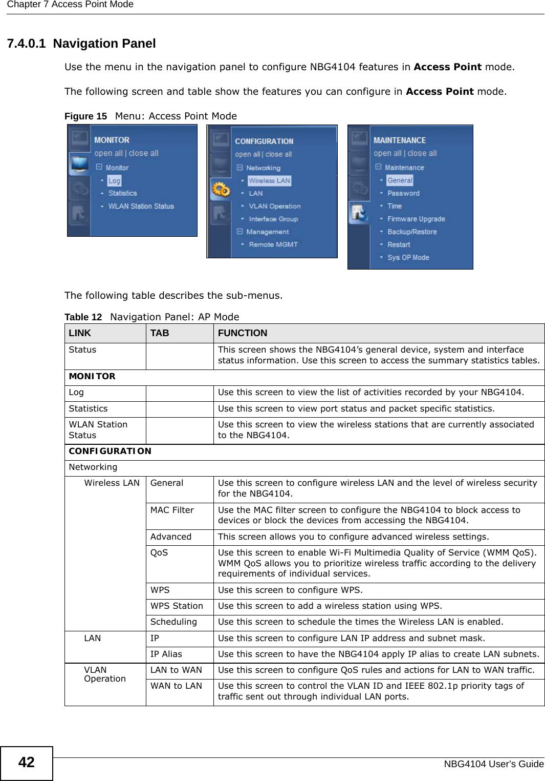
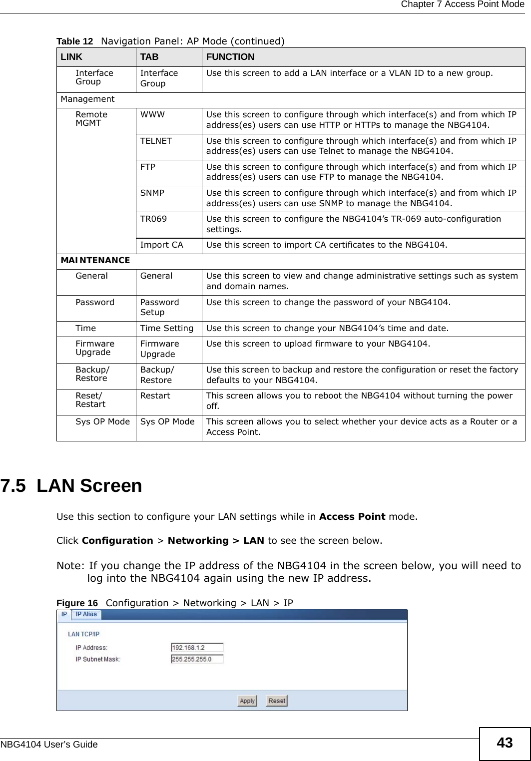
Navigation menu
Upload a User Manual
Namespaces
Wiki Guide
HTML
PDF
Info
Views
User Manual
Discussion / Help
Navigation
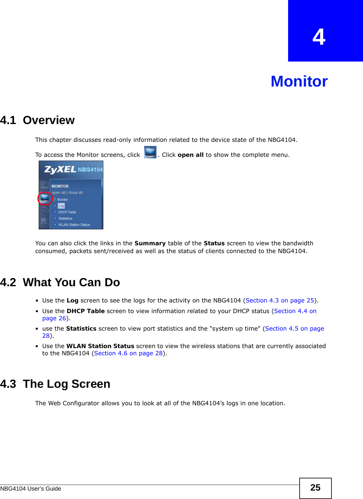
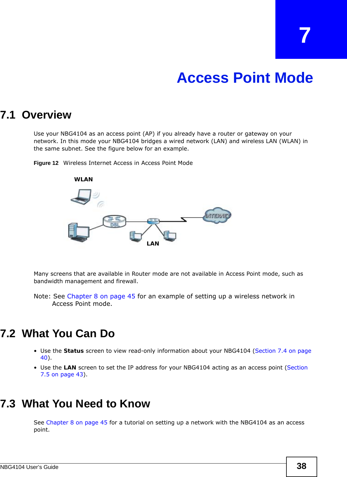
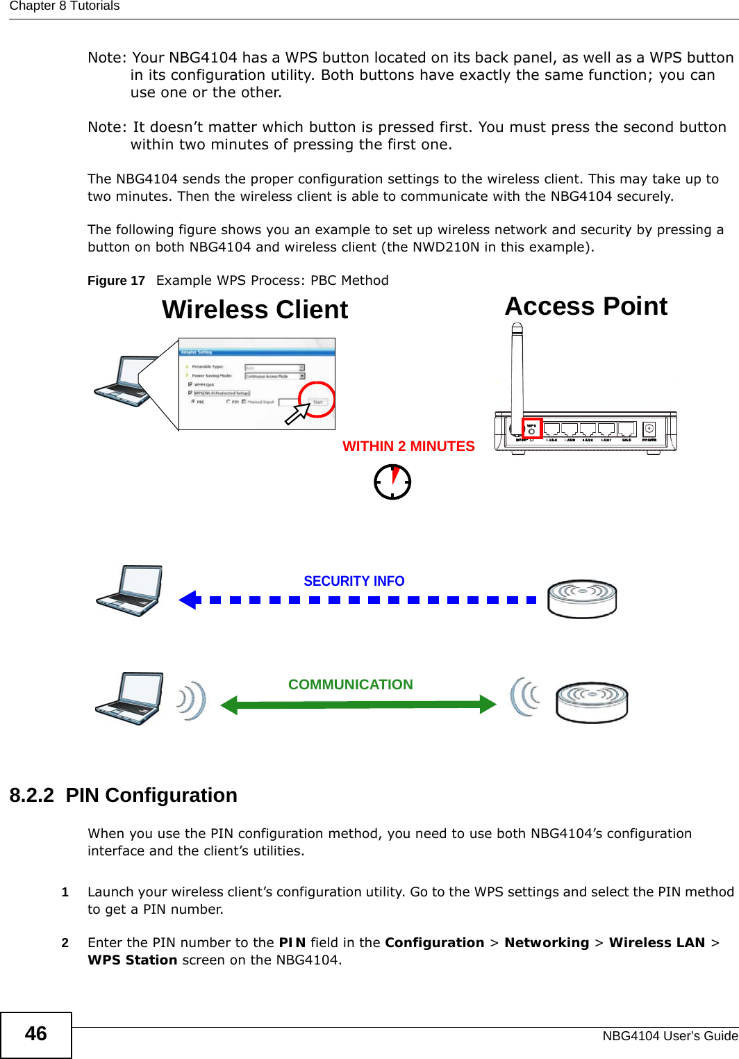
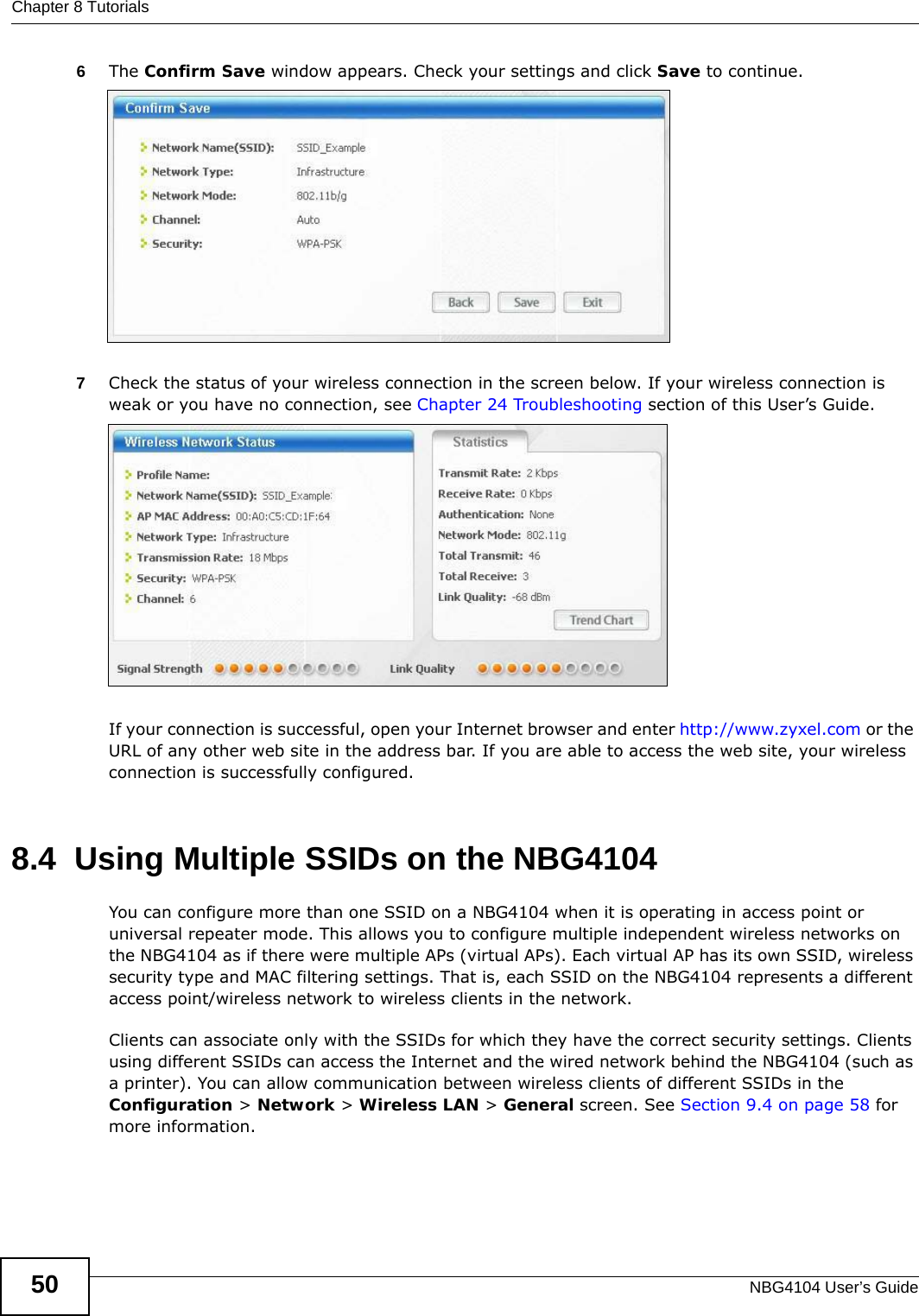
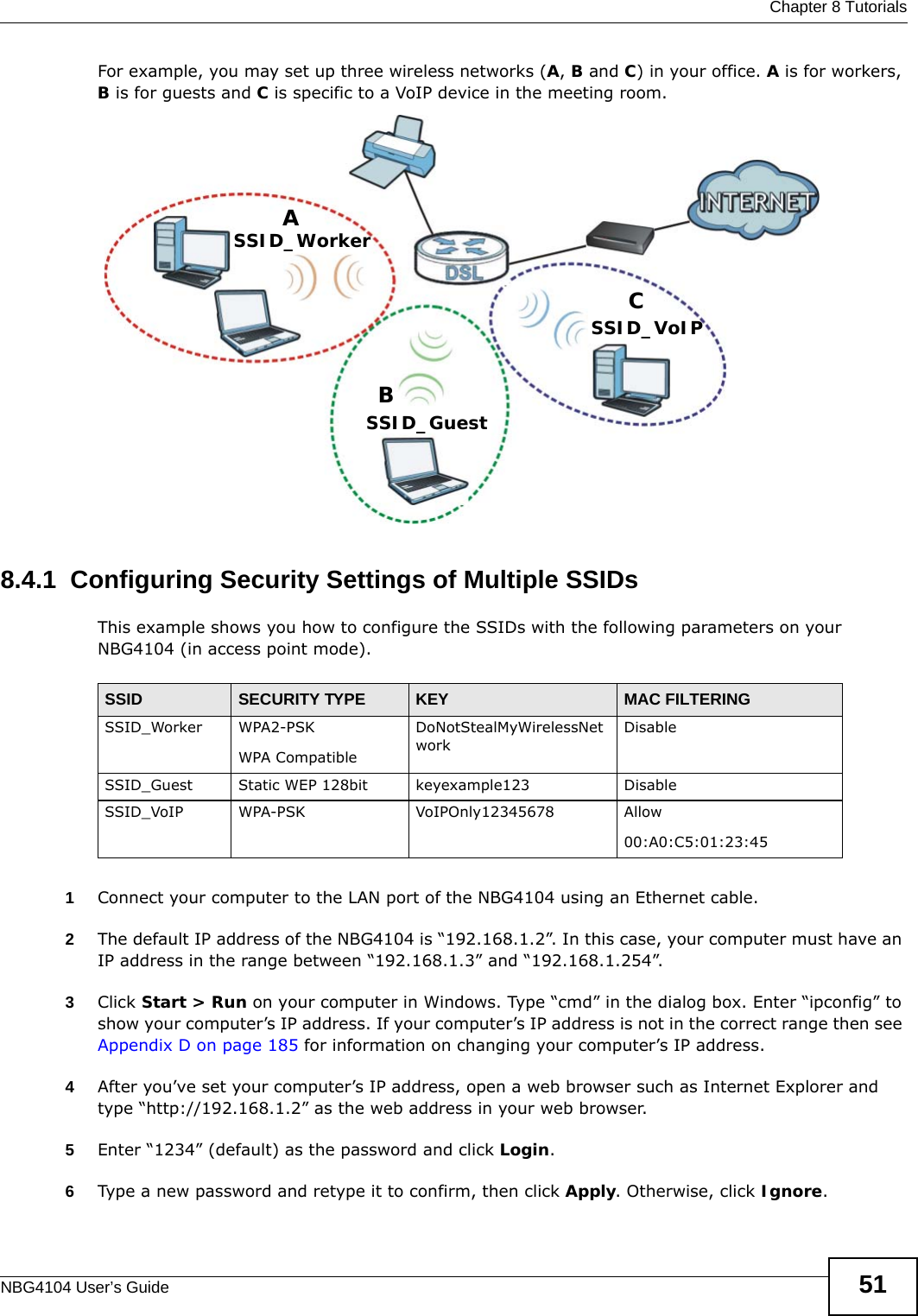
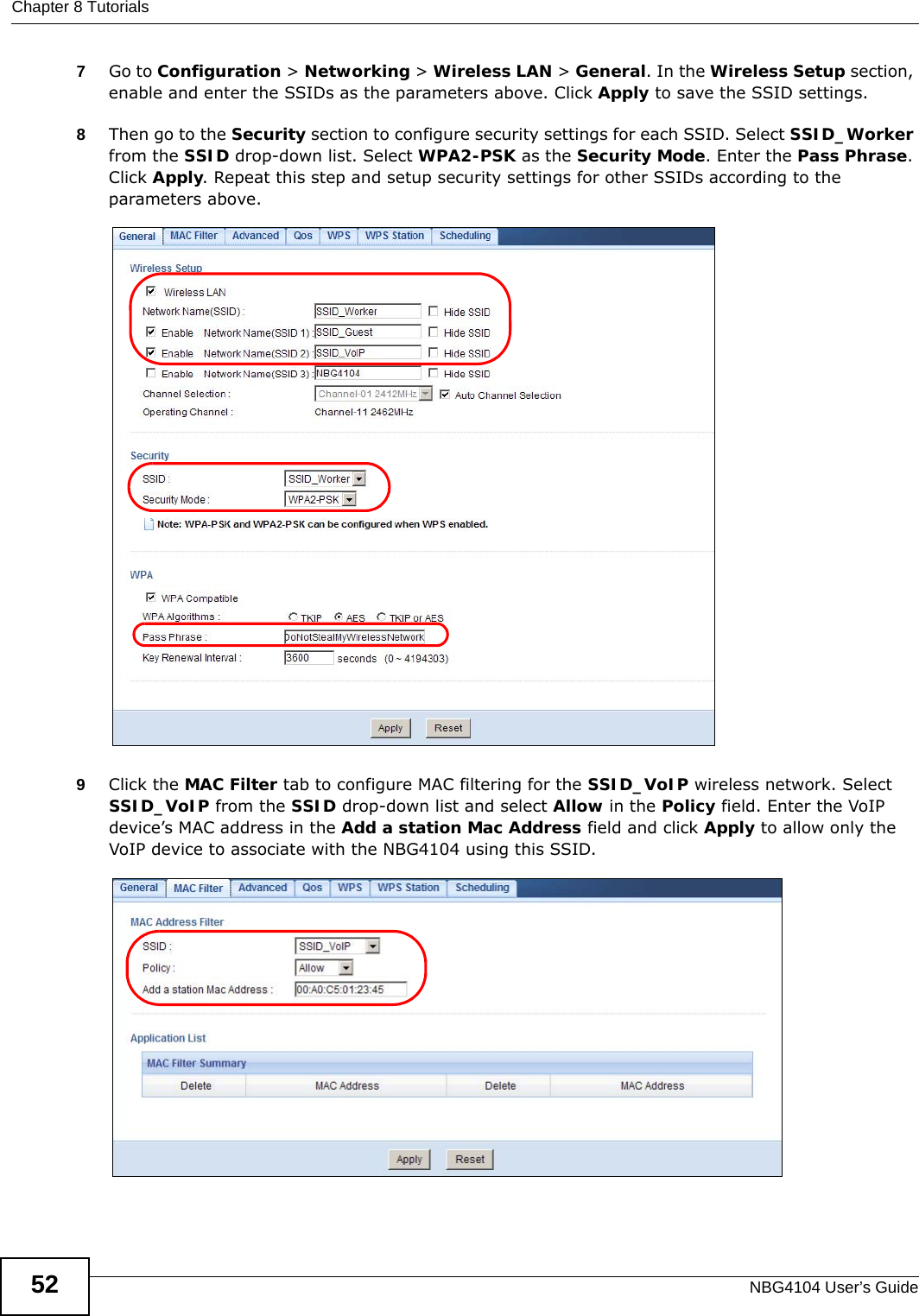
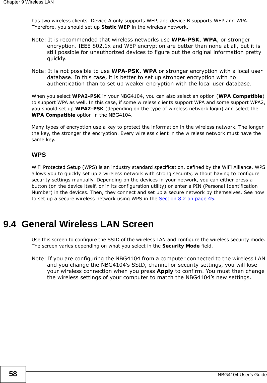
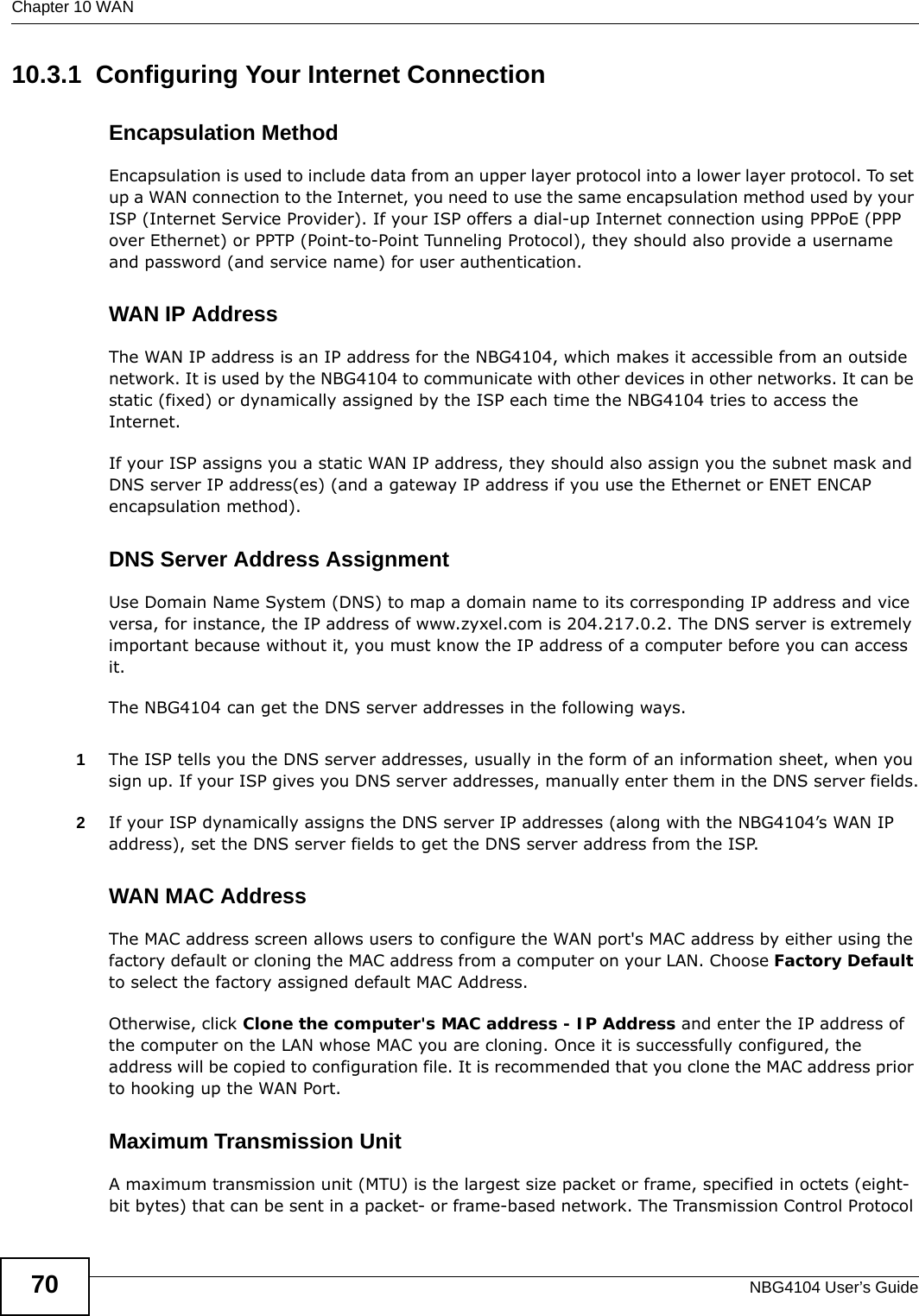
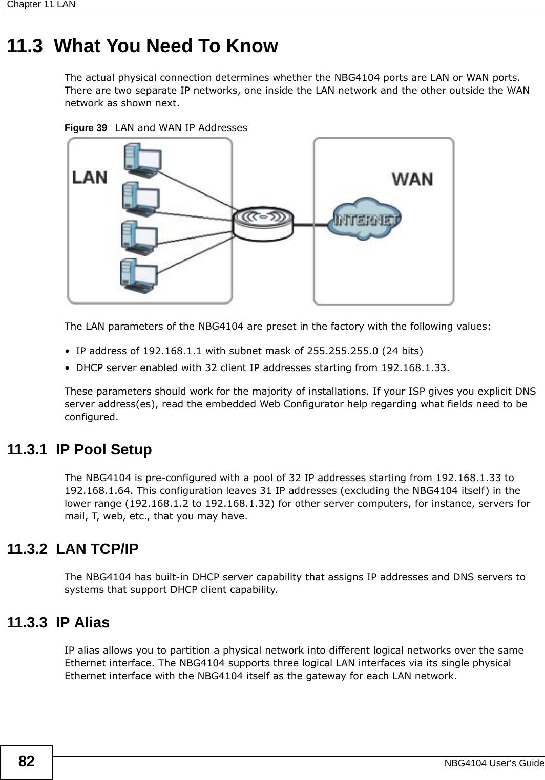
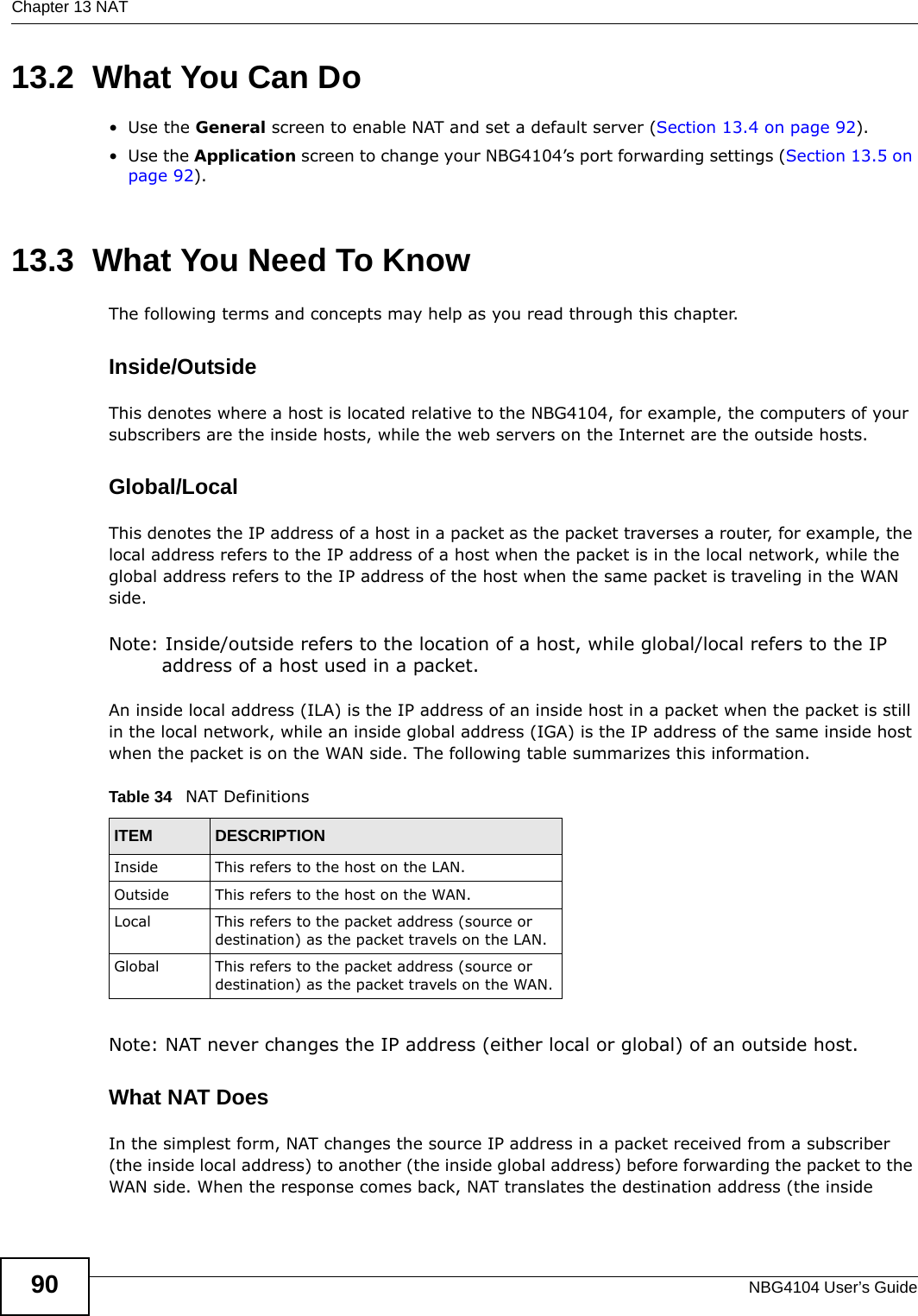
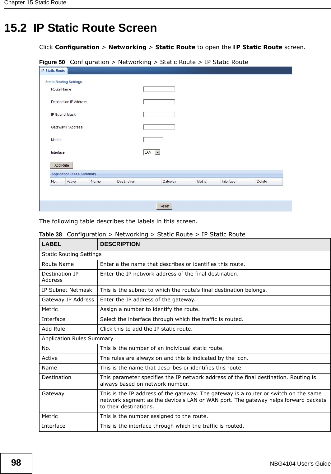
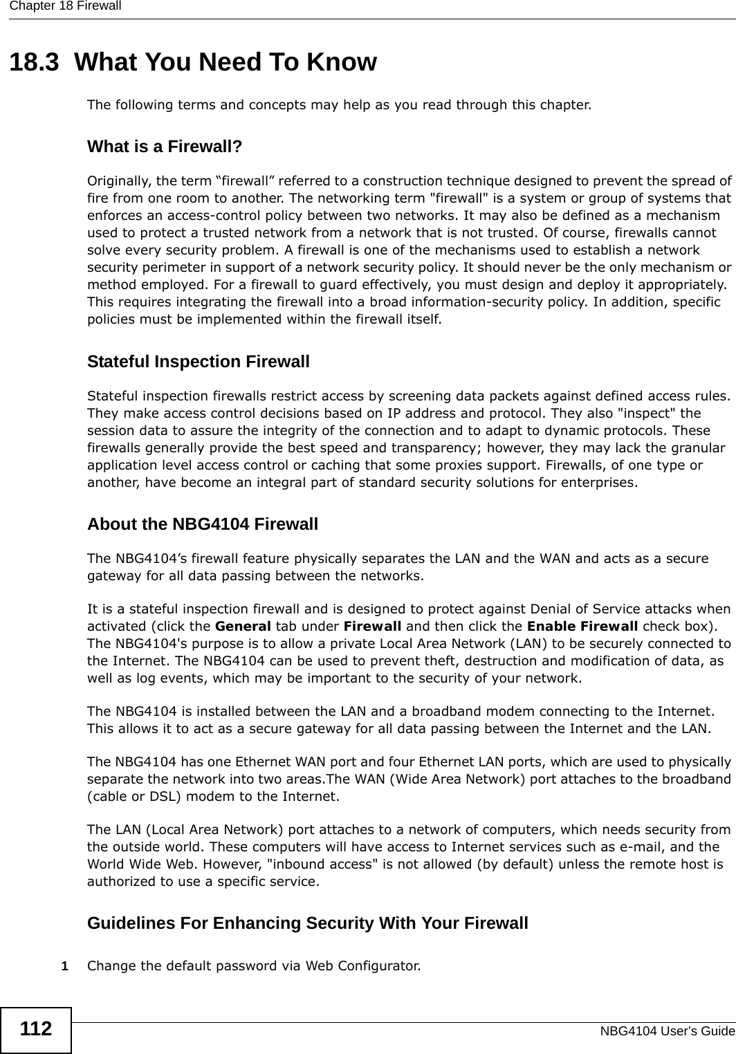
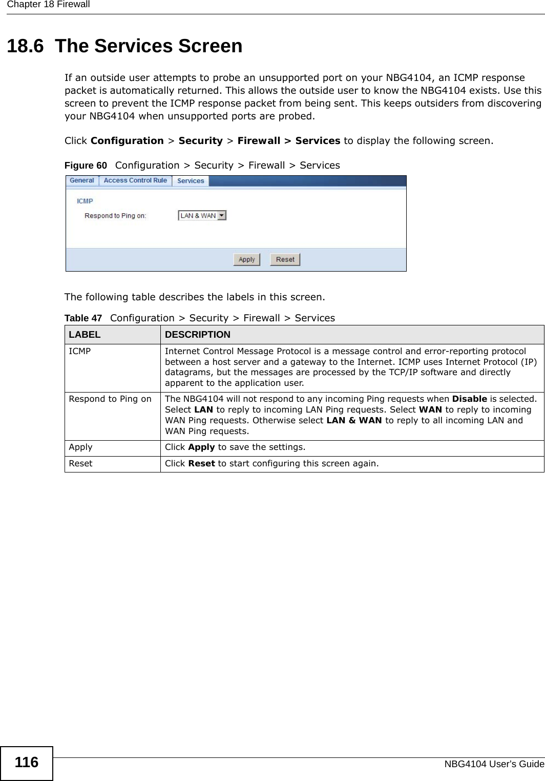
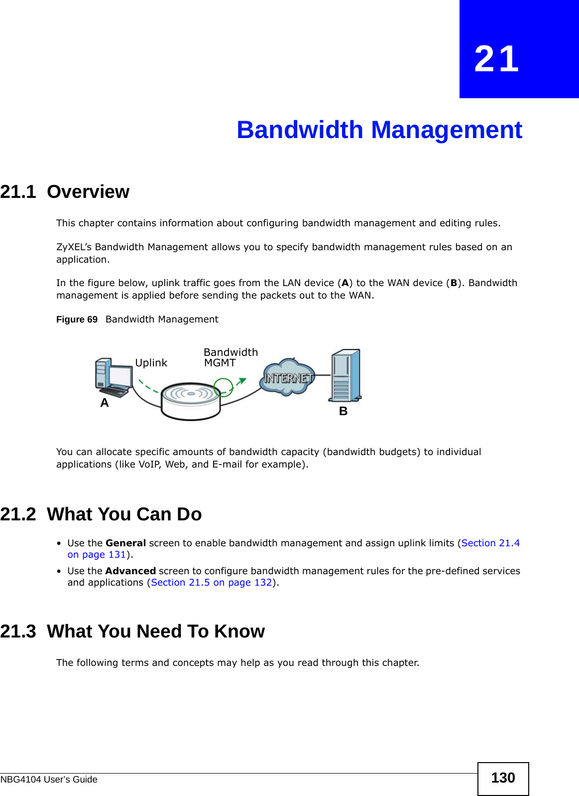
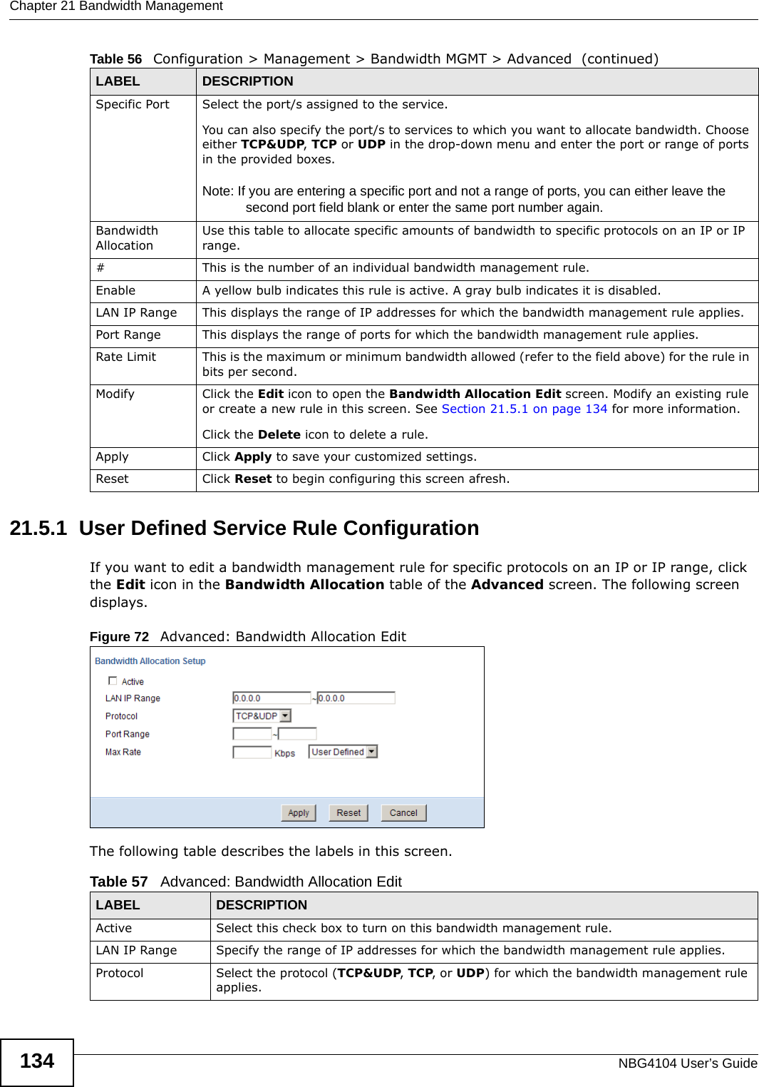
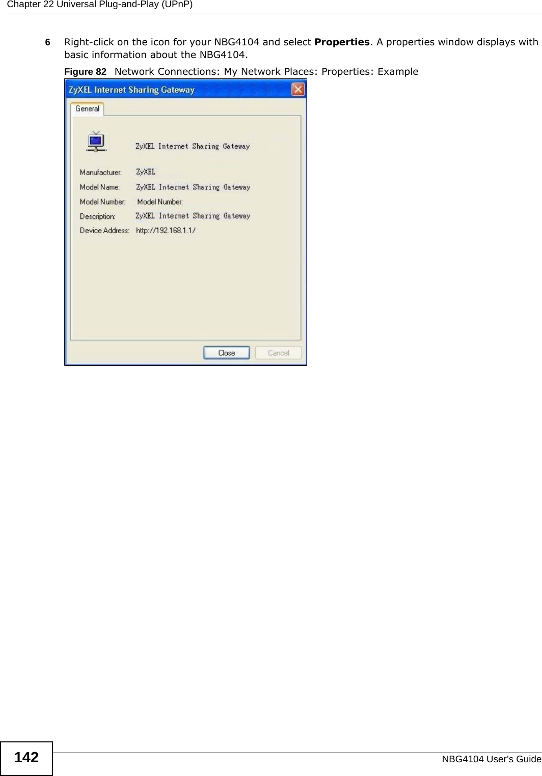
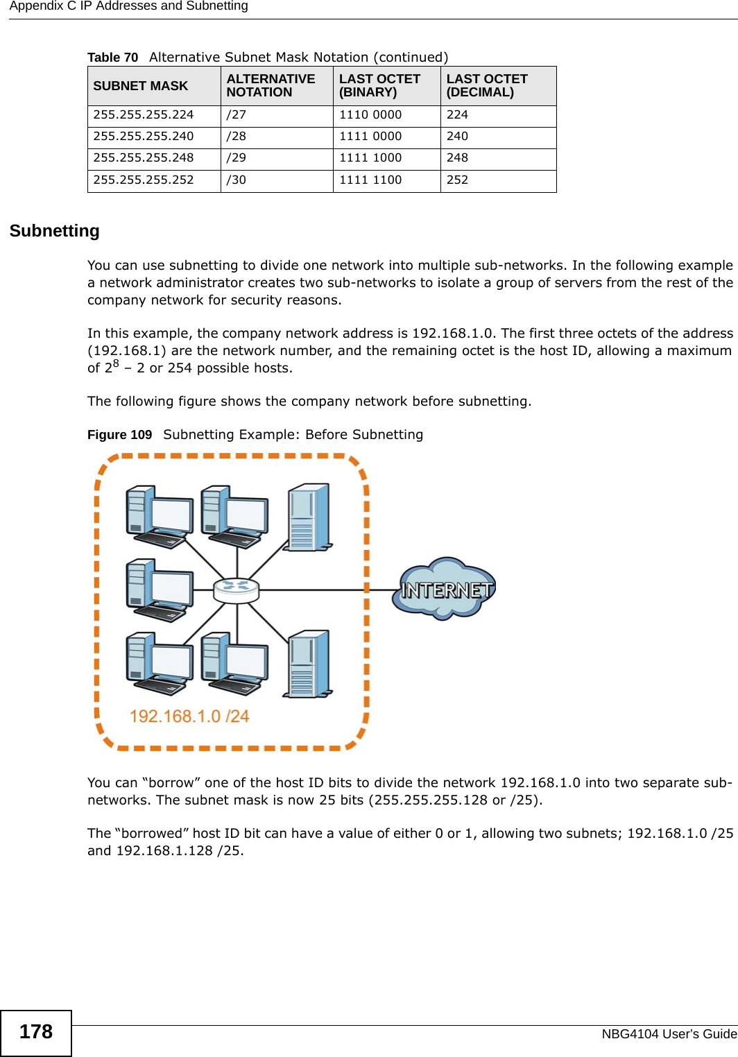
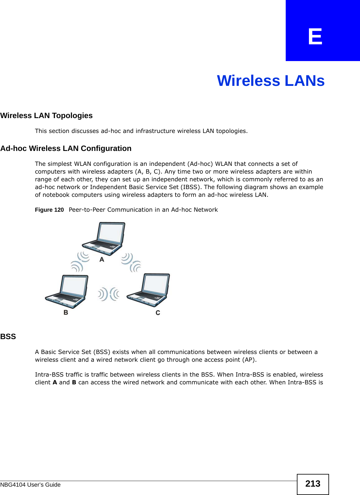
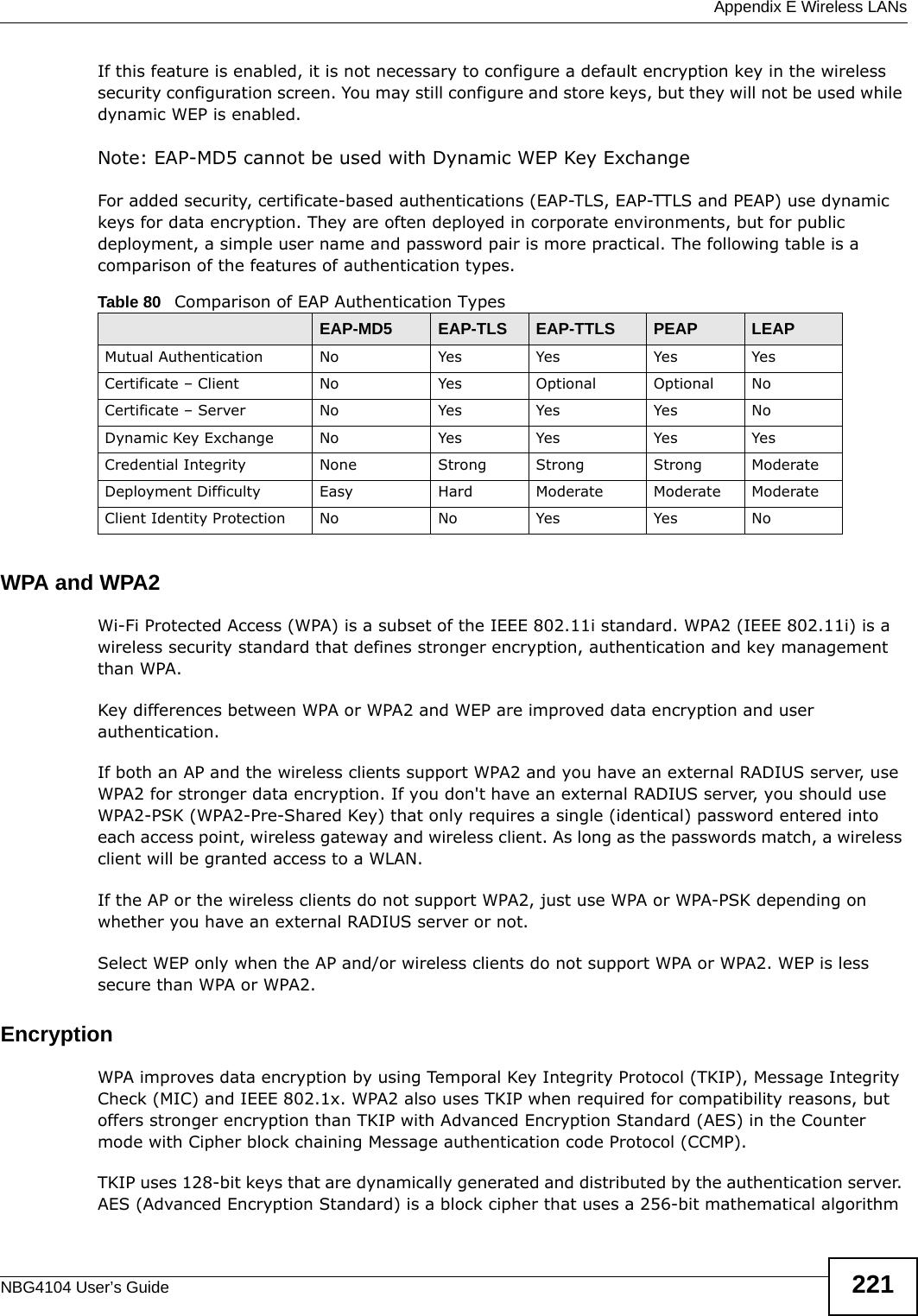
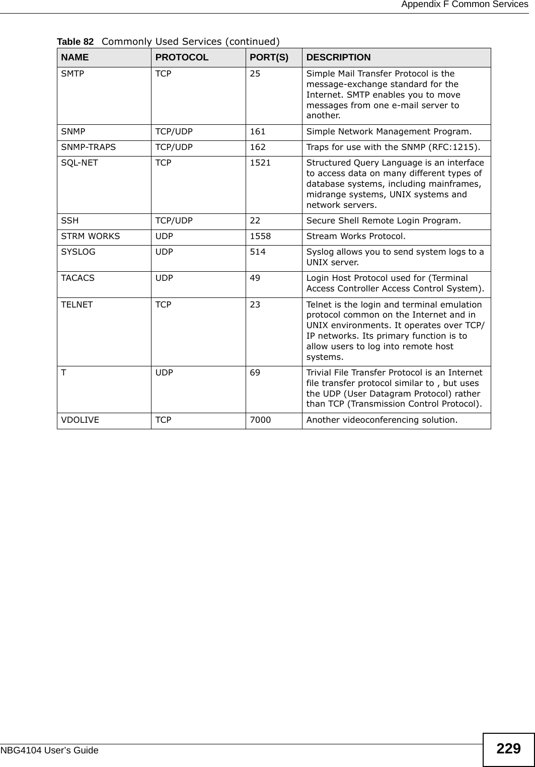
![About This User's GuideNBG4104 User’s Guide 3About This User's GuideIntended AudienceThis manual is intended for people who want to configure the NBG4104 using the Web Configurator. Tips for Reading User’s Guides On-ScreenWhen reading a ZyXEL User’s Guide On-Screen, keep the following in mind:• If you don’t already have the latest version of Adobe Reader, you can download it from http://www.adobe.com.• Use the PDF’s bookmarks to quickly navigate to the areas that interest you. Adobe Reader’s bookmarks pane opens by default in all ZyXEL User’s Guide PDFs.• If you know the page number or know vaguely which page-range you want to view, you can enter a number in the toolbar in Reader, then press [ENTER] to jump directly to that page.• Type [CTRL]+[F] to open the Adobe Reader search utility and enter a word or phrase. This can help you quickly pinpoint the information you require. You can also enter text directly into the toolbar in Reader.• To quickly move around within a page, press the [SPACE] bar. This turns your cursor into a “hand” with which you can grab the page and move it around freely on your screen.• Embedded hyperlinks are actually cross-references to related text. Click them to jump to the corresponding section of the User’s Guide PDF.Related Documentation•Quick Start Guide The Quick Start Guide is designed to help you get your NBG4104 up and running right away. It contains information on setting up your network and configuring for Internet access.•Support DiscRefer to the included CD for support documents.](https://usermanual.wiki/ZyXEL-Communications/NBG4104/User-Guide-1621838-Page-3.png)
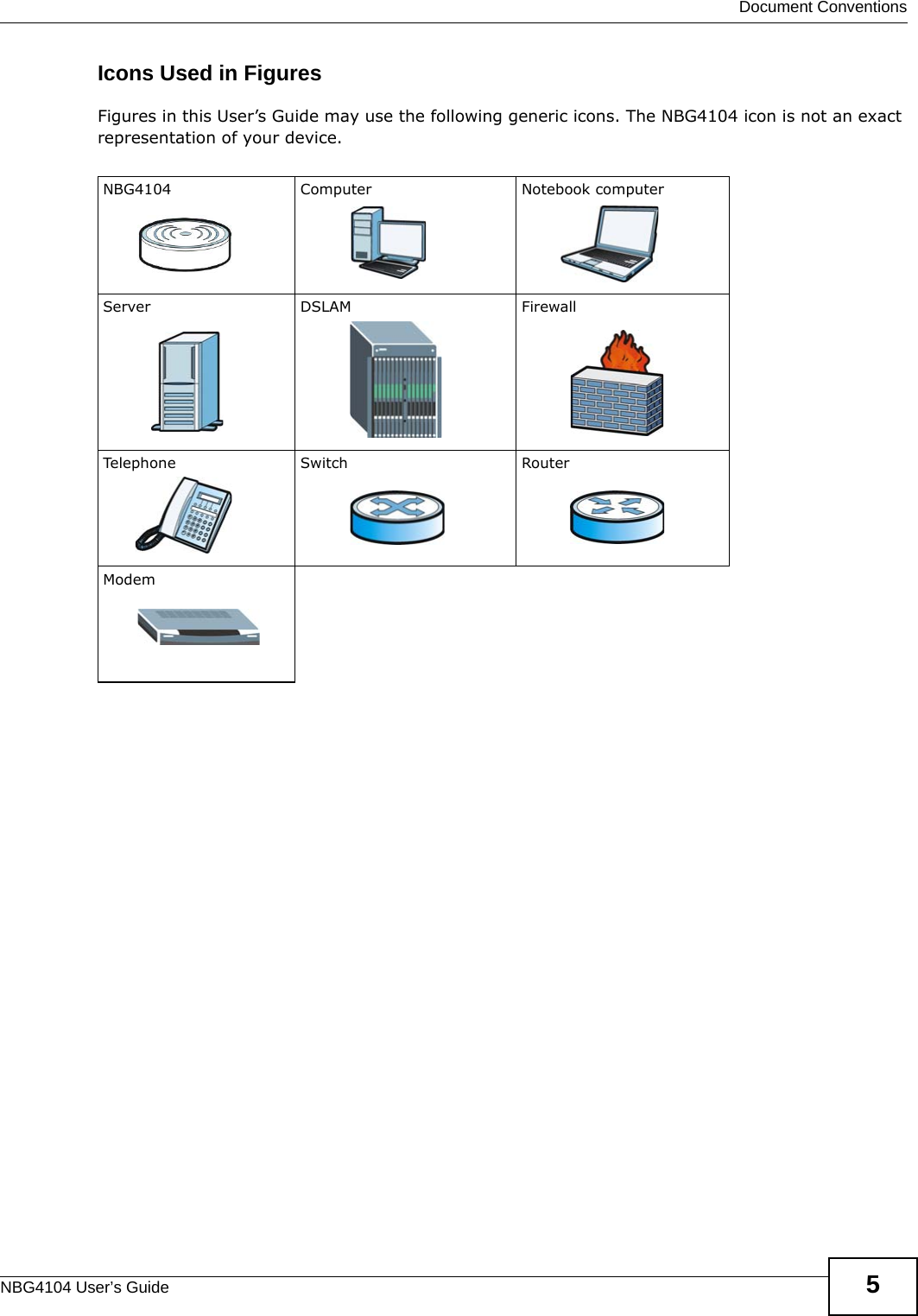
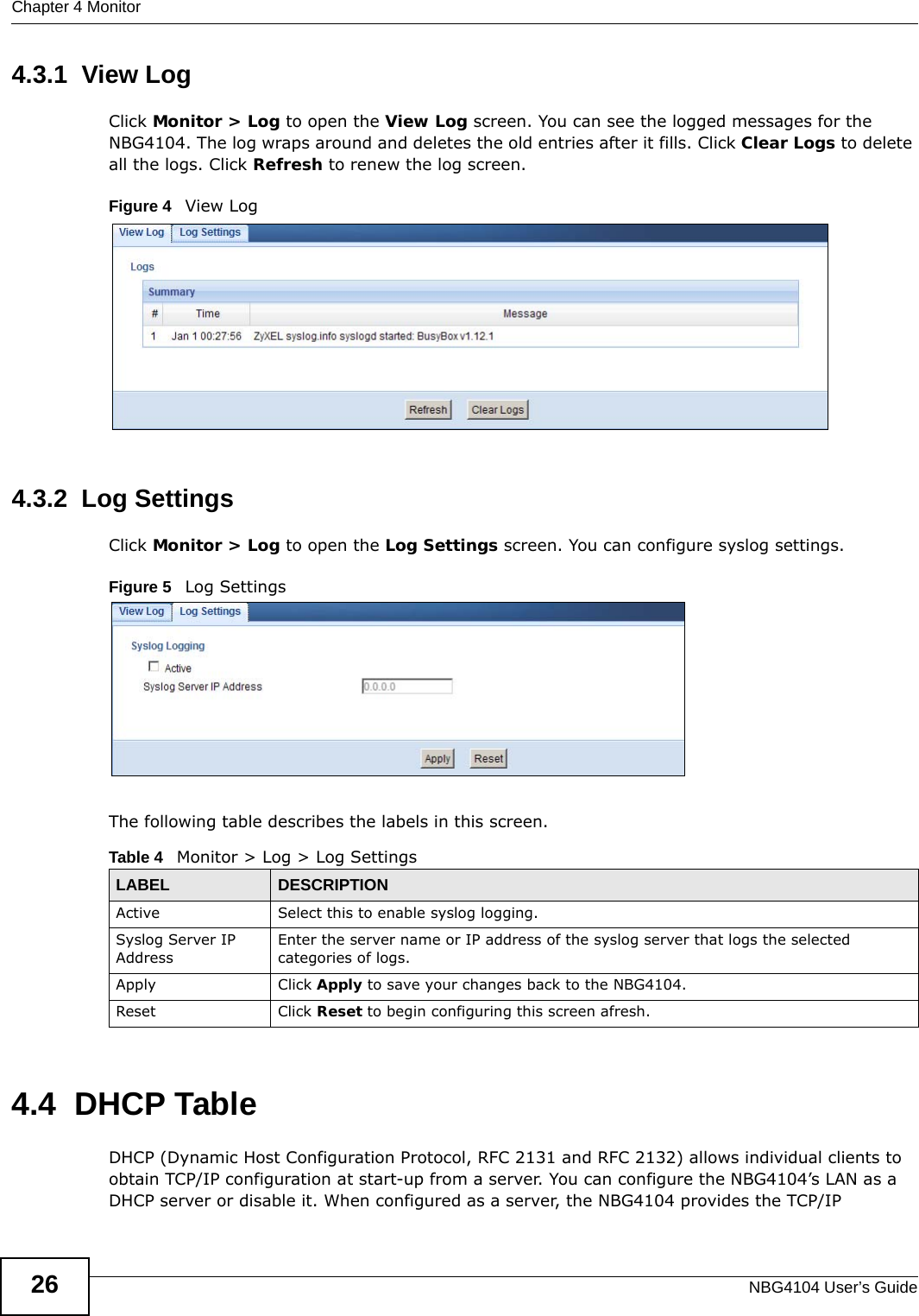
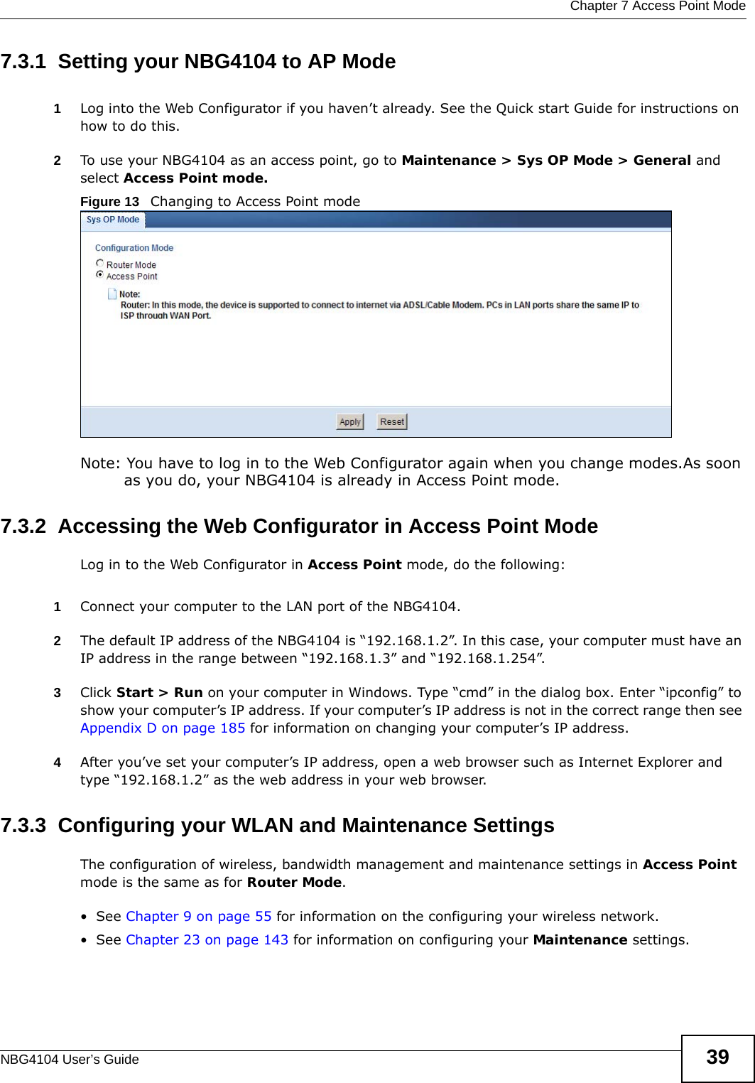
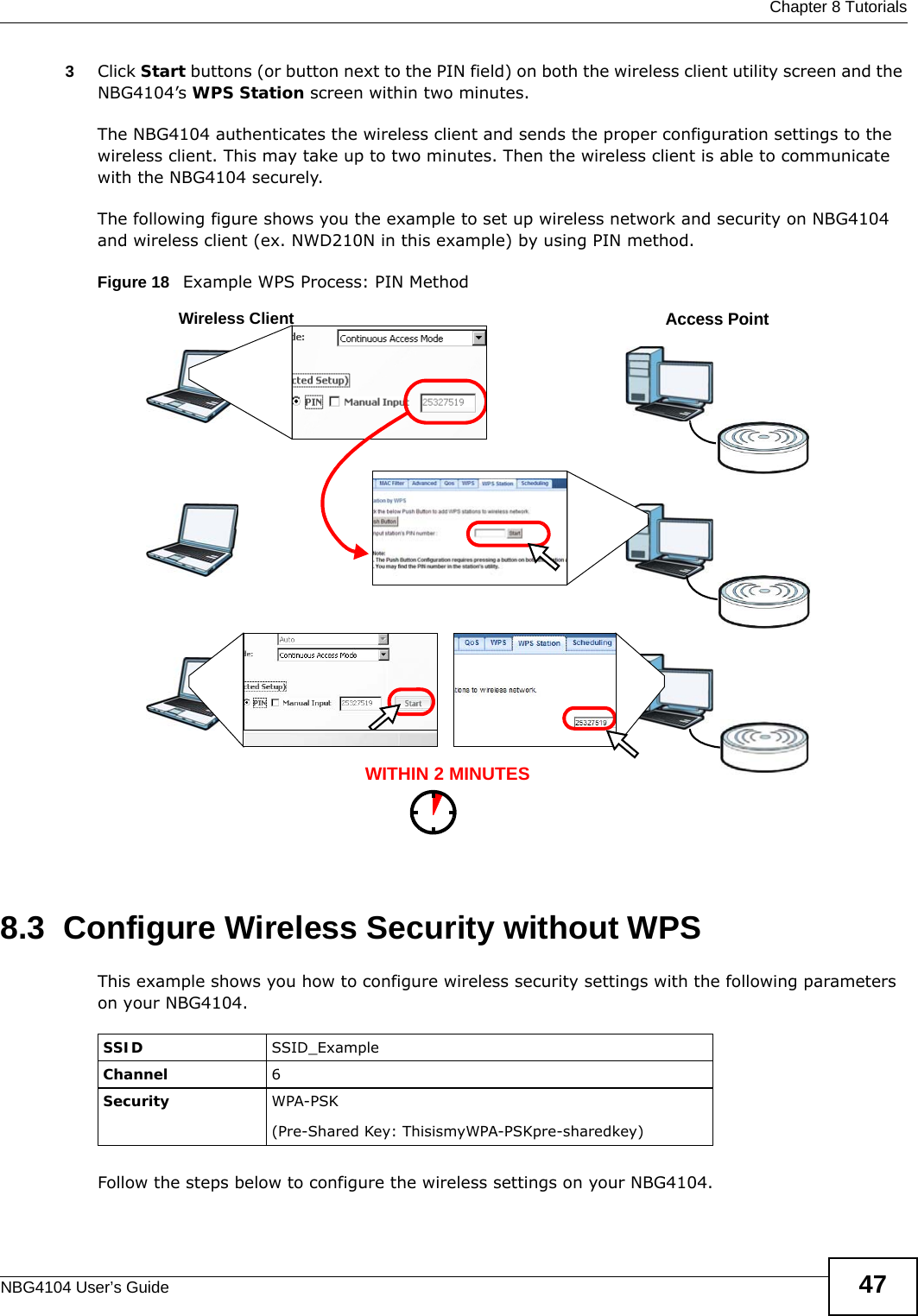
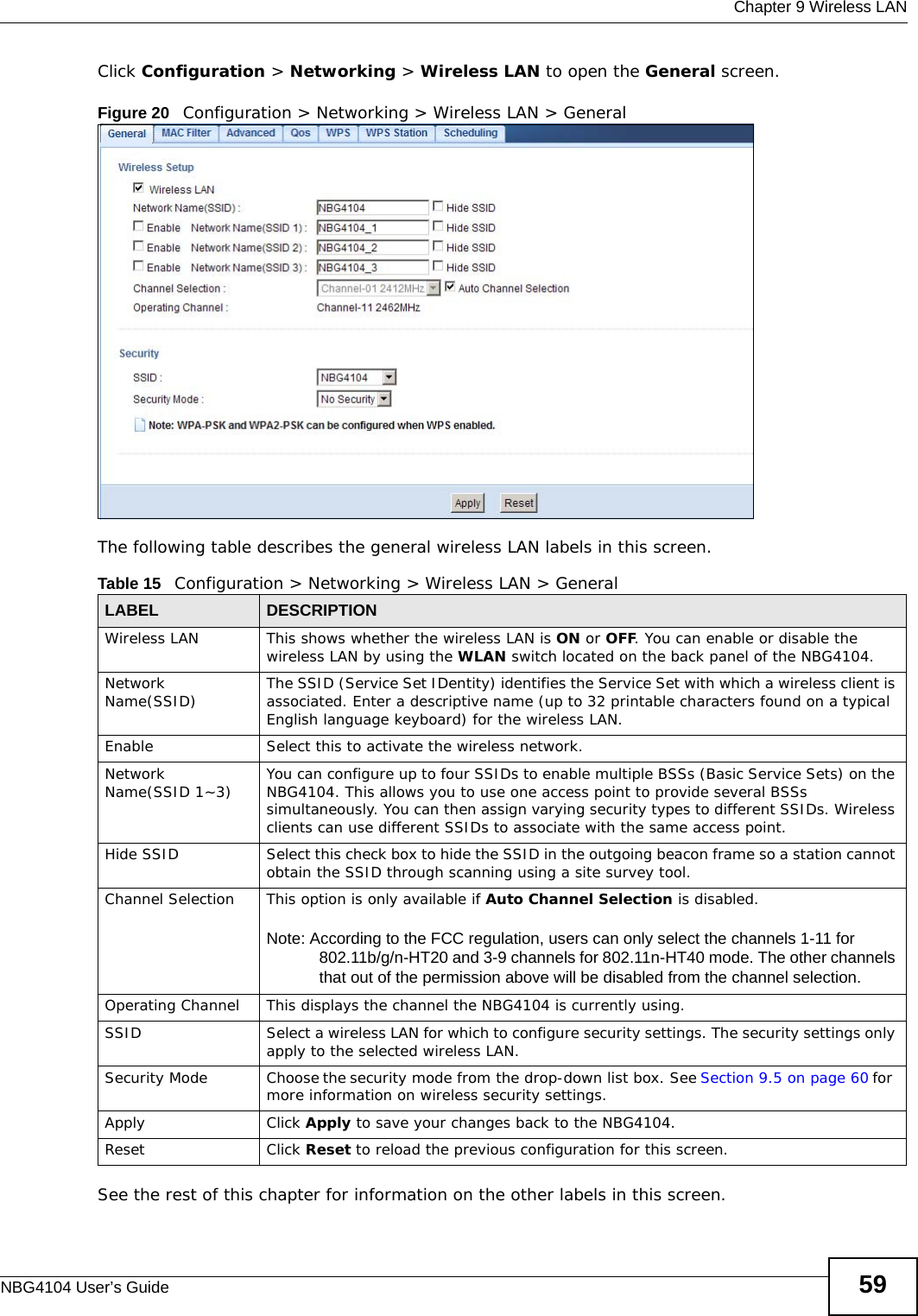
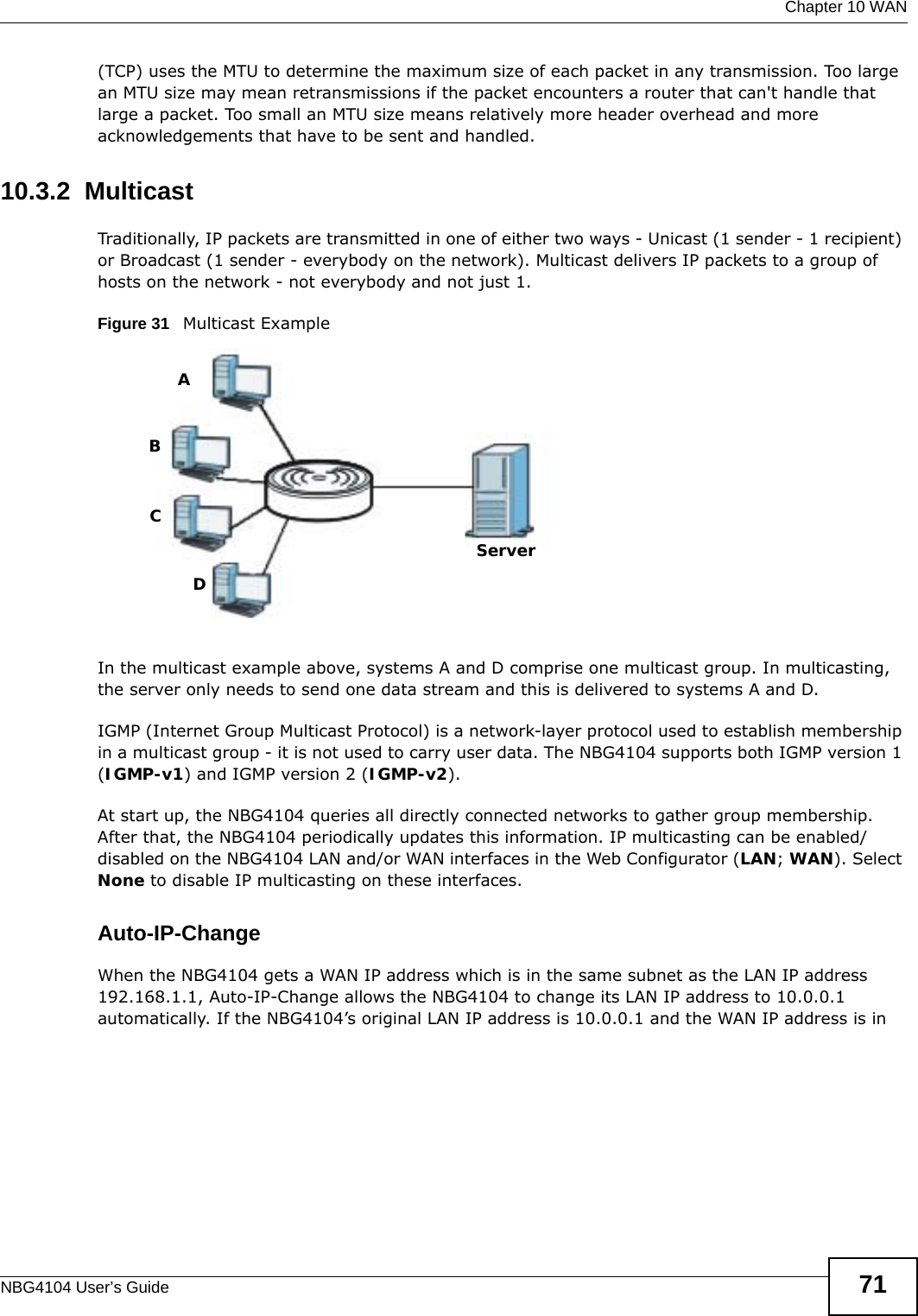
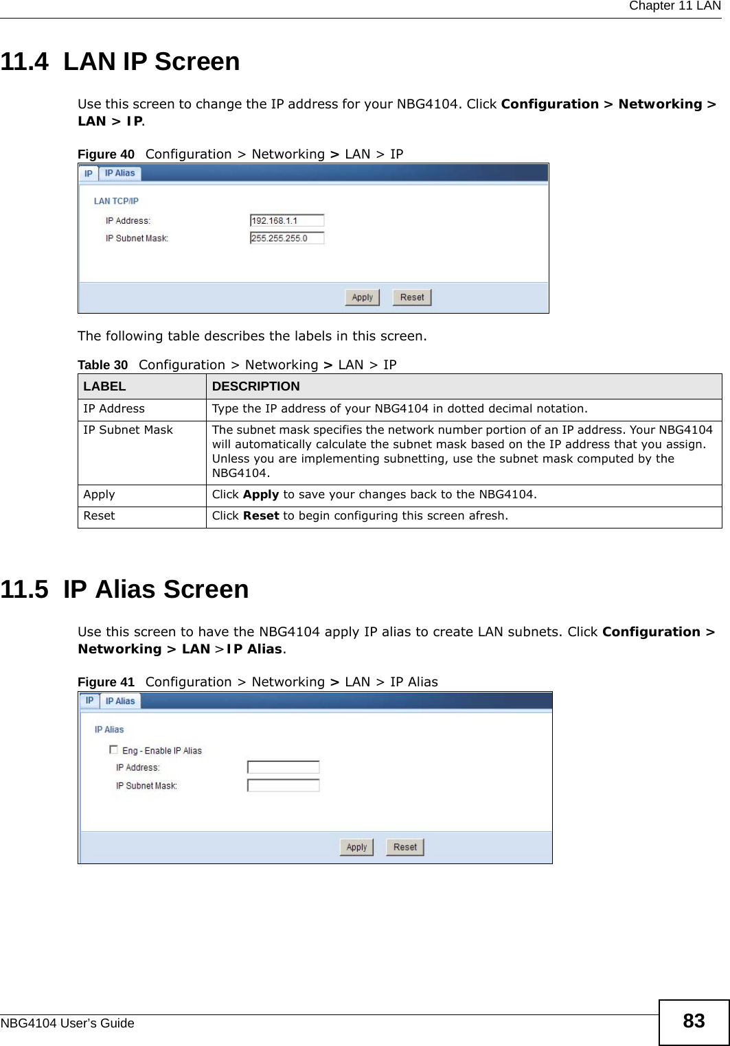
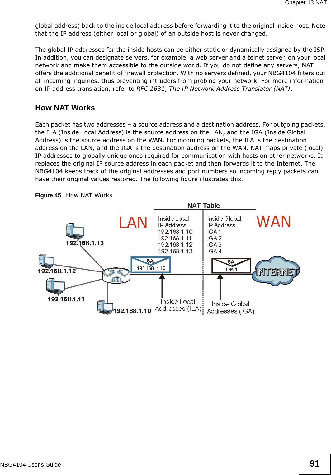
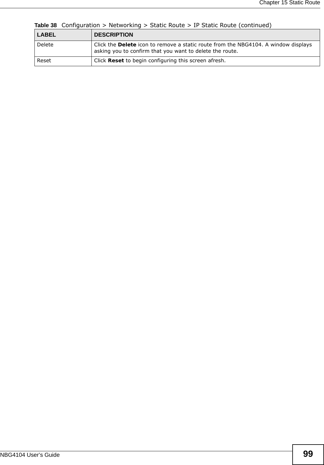
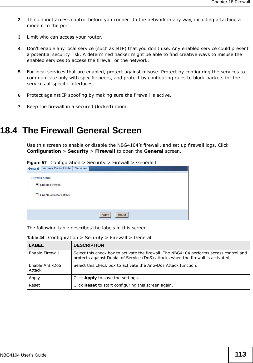
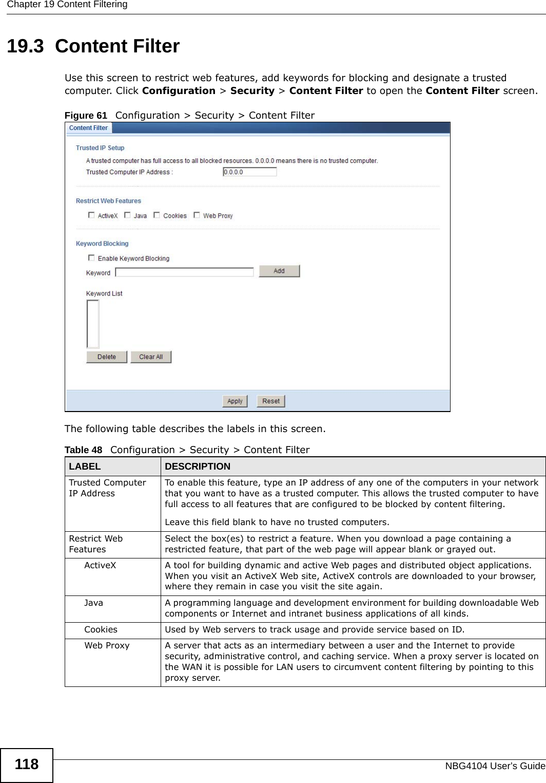
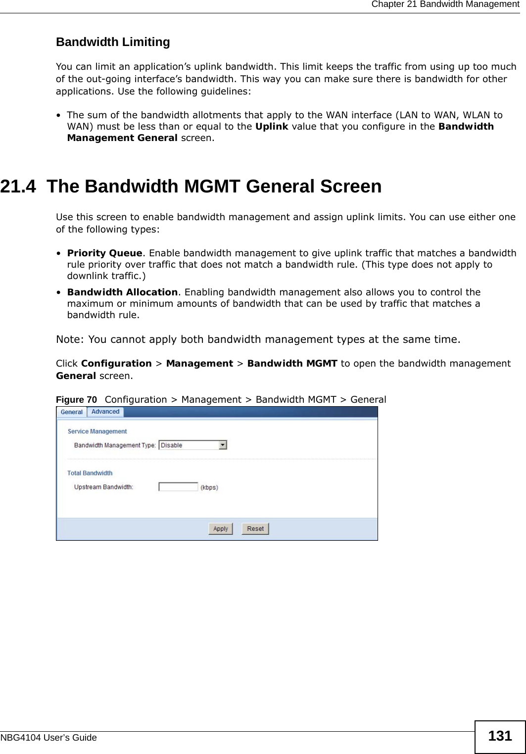
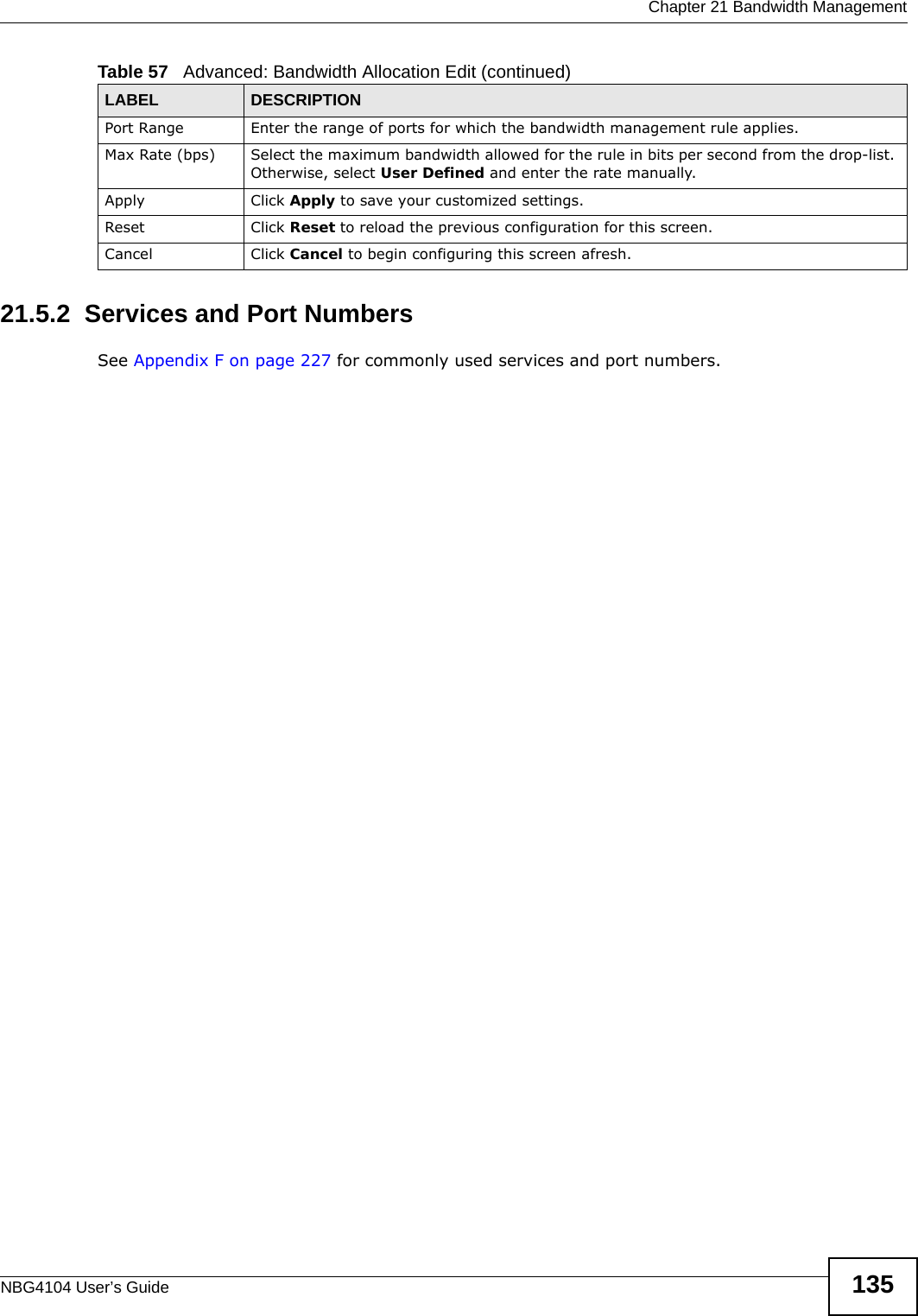
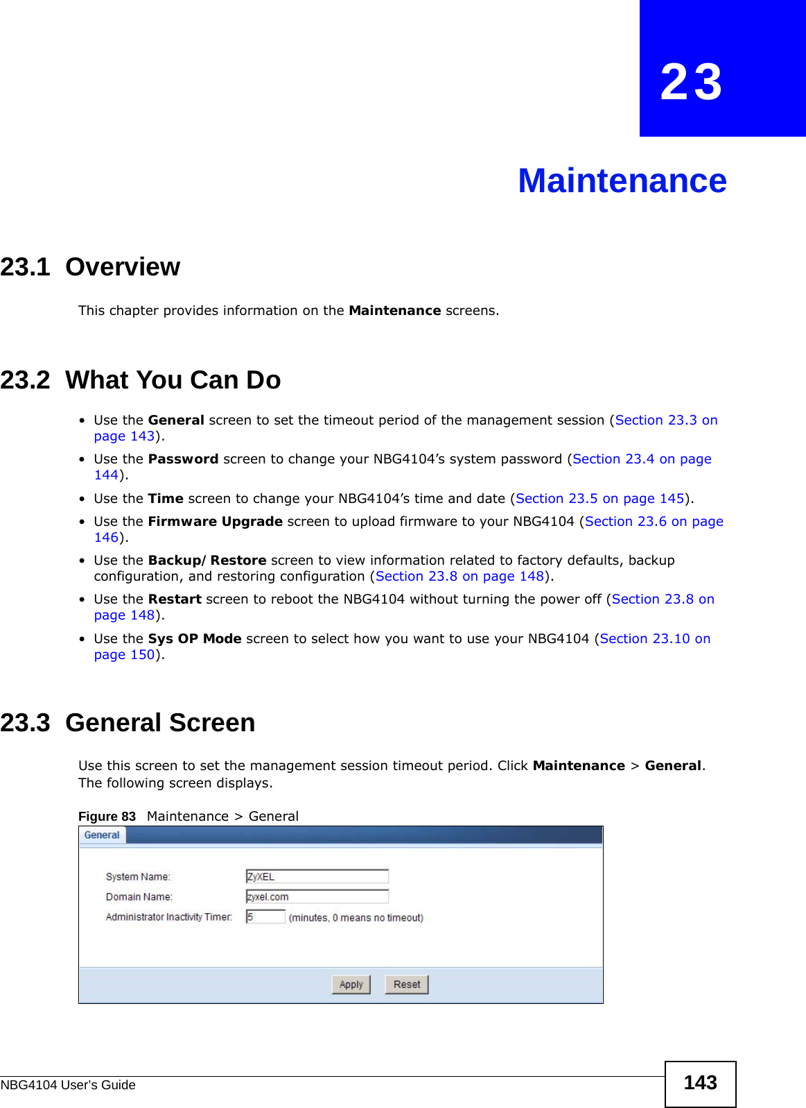
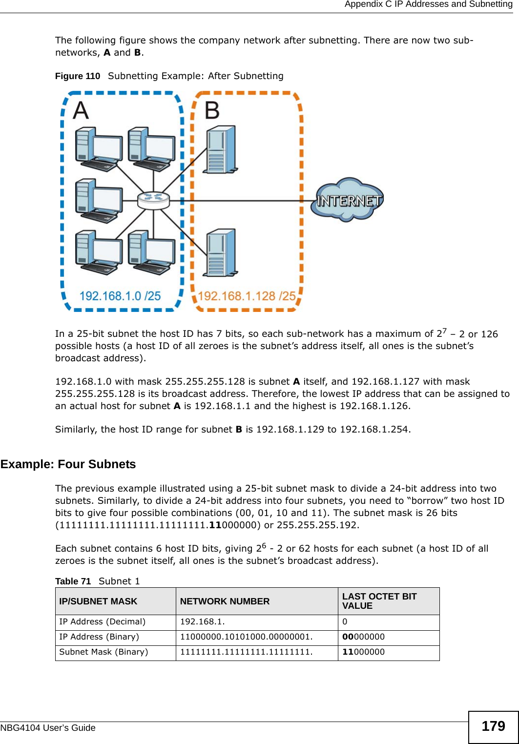
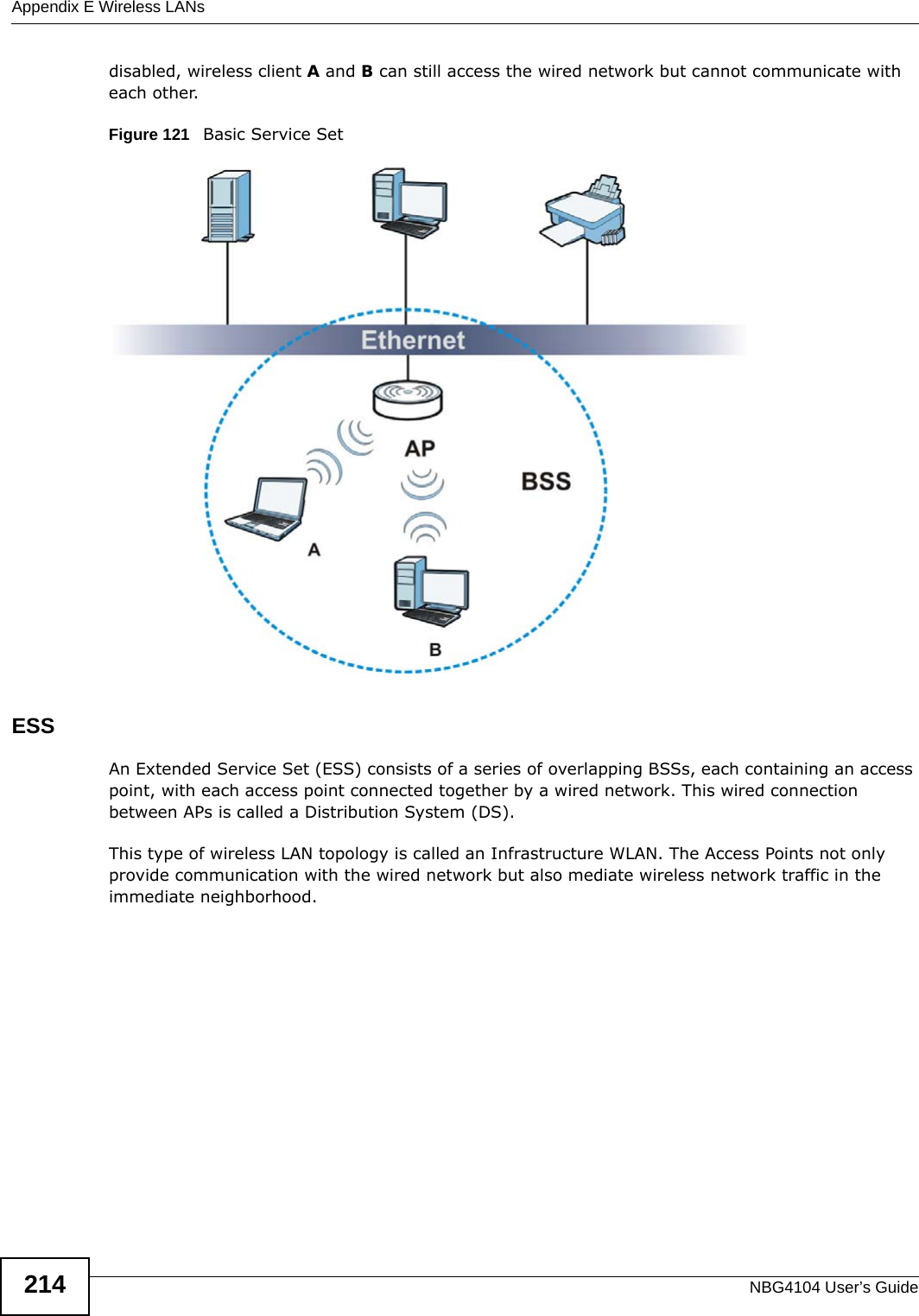
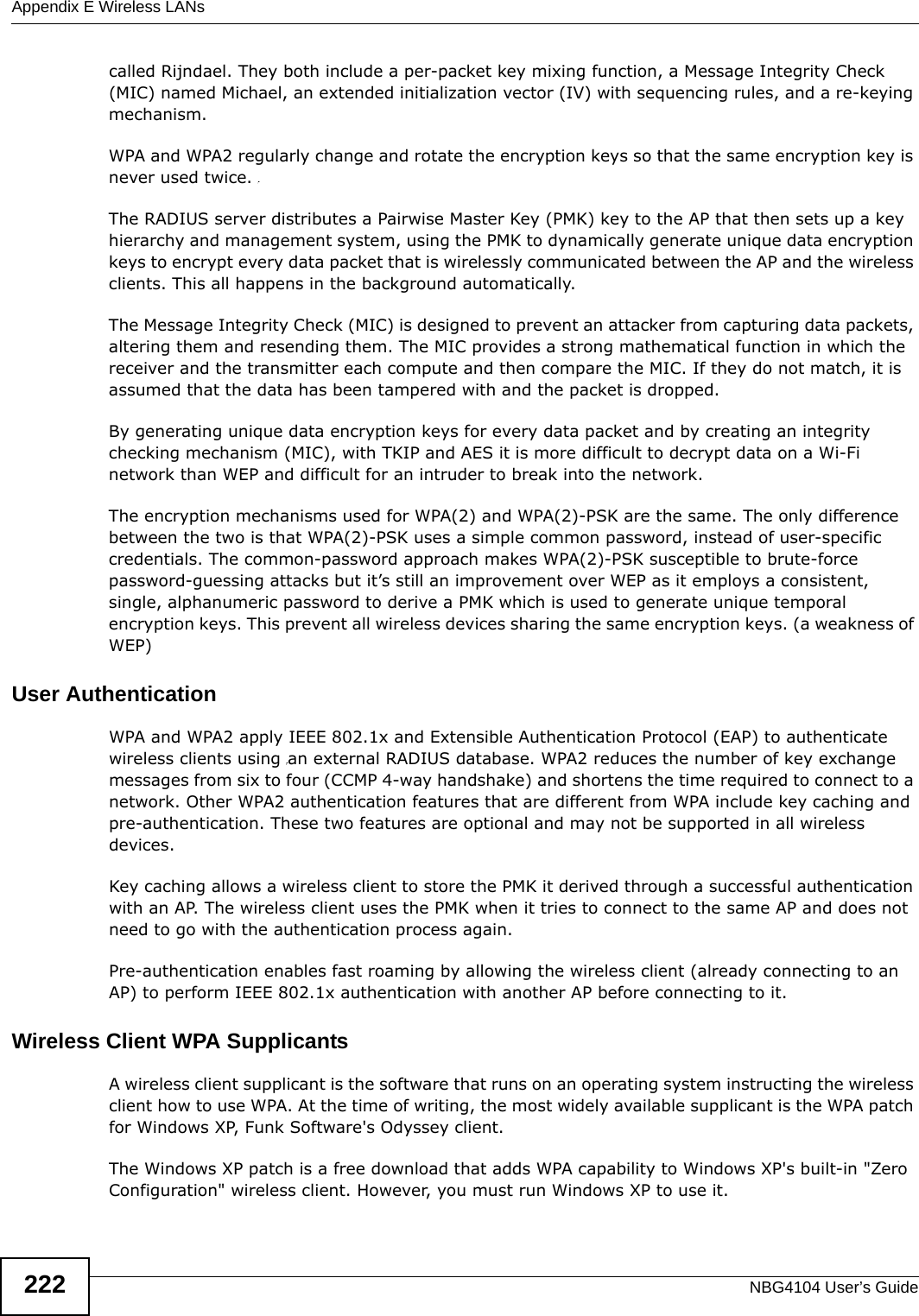
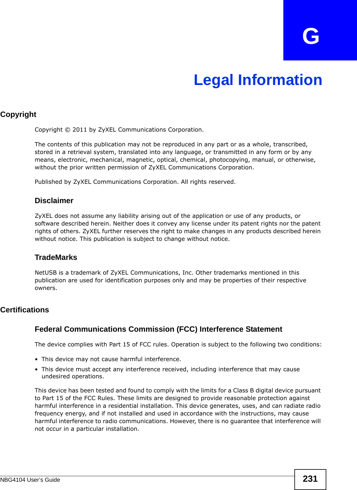
![Document ConventionsNBG4104 User’s Guide4Document ConventionsWarnings and NotesThese are how warnings and notes are shown in this User’s Guide. Warnings tell you about things that could harm you or your device.Note: Notes tell you other important information (for example, other things you may need to configure or helpful tips) or recommendations.Syntax Conventions• The NBG4104 may be referred to as the “NBG4104”, the “device”, the “product” or the “system” in this User’s Guide.• Product labels, screen names, field labels and field choices are all in bold font.• A key stroke is denoted by square brackets and uppercase text, for example, [ENTER] means the “enter” or “return” key on your keyboard.• “Enter” means for you to type one or more characters and then press the [ENTER] key. “Select” or “choose” means for you to use one of the predefined choices.• A right angle bracket ( > ) within a screen name denotes a mouse click. For example, Maintenance > Log > Log Setting means you first click Maintenance in the navigation panel, then the Log sub menu and finally the Log Setting tab to get to that screen.• Units of measurement may denote the “metric” value or the “scientific” value. For example, “k” for kilo may denote “1000” or “1024”, “M” for mega may denote “1000000” or “1048576” and so on.• “e.g.,” is a shorthand for “for instance”, and “i.e.,” means “that is” or “in other words”.](https://usermanual.wiki/ZyXEL-Communications/NBG4104/User-Guide-1621838-Page-4.png)
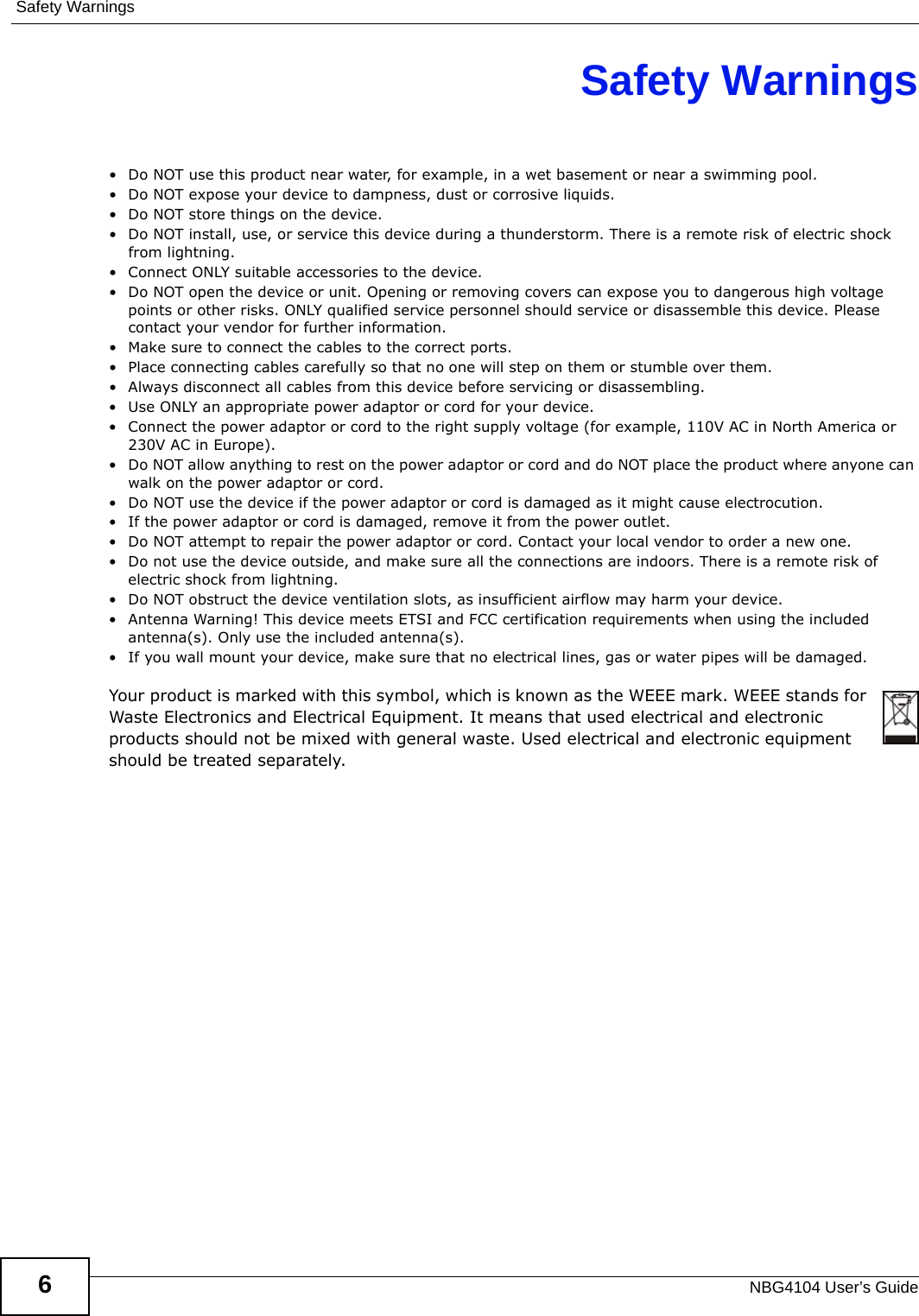

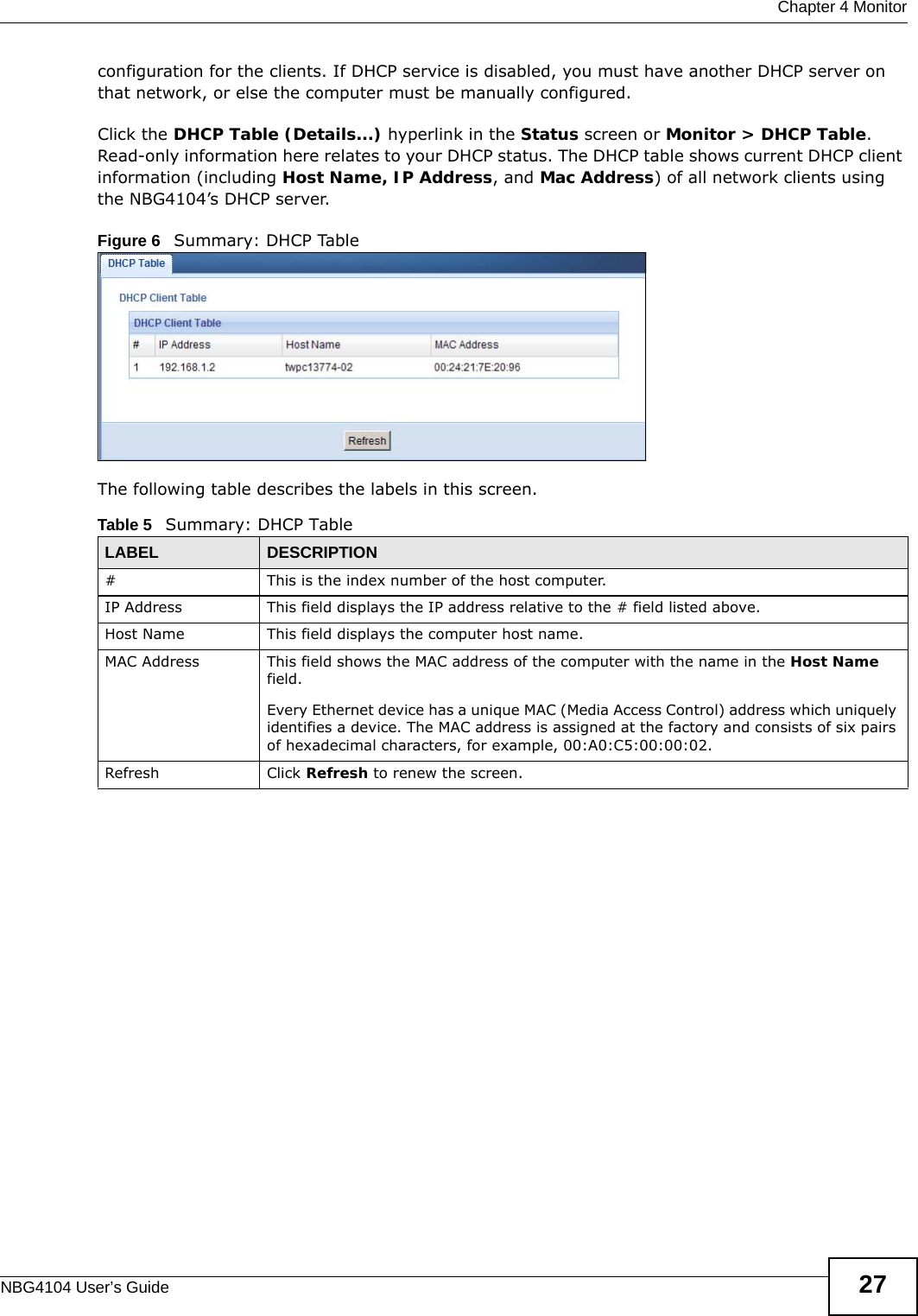

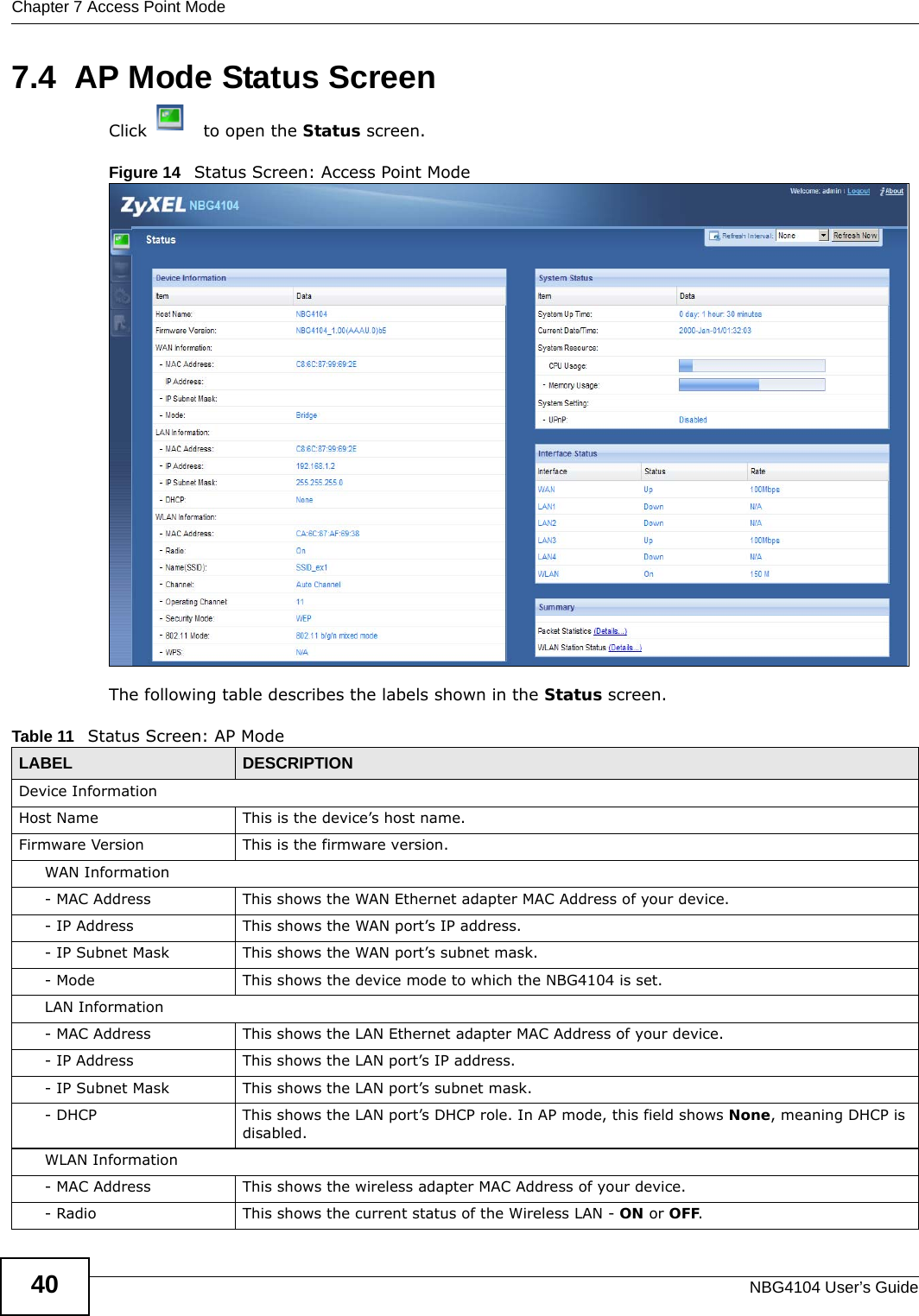
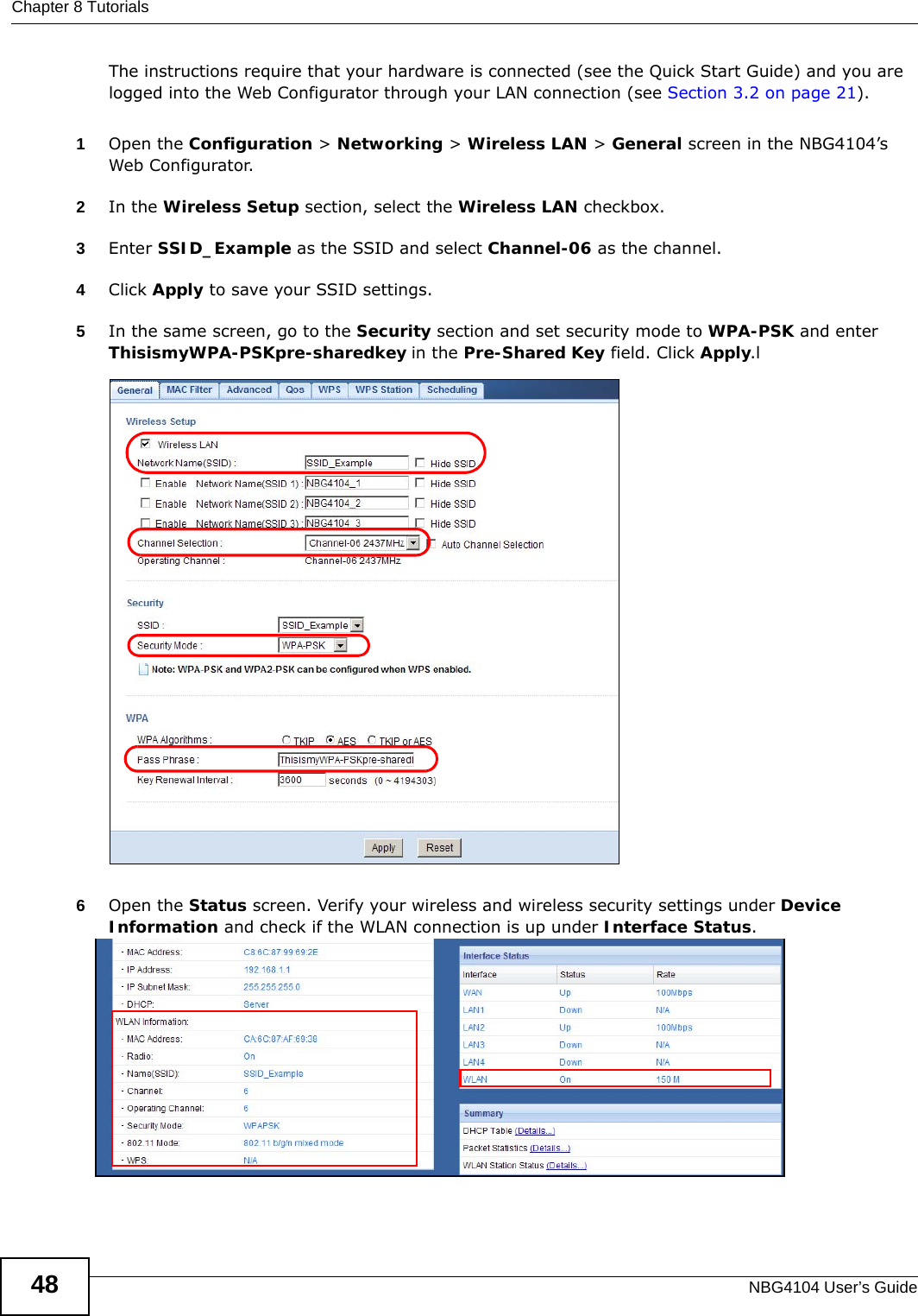
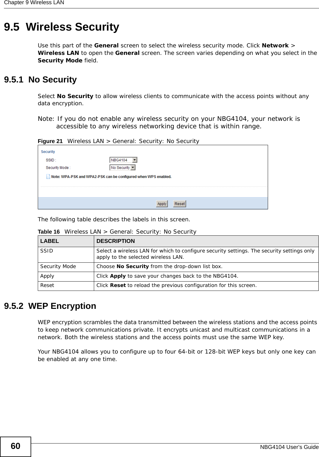
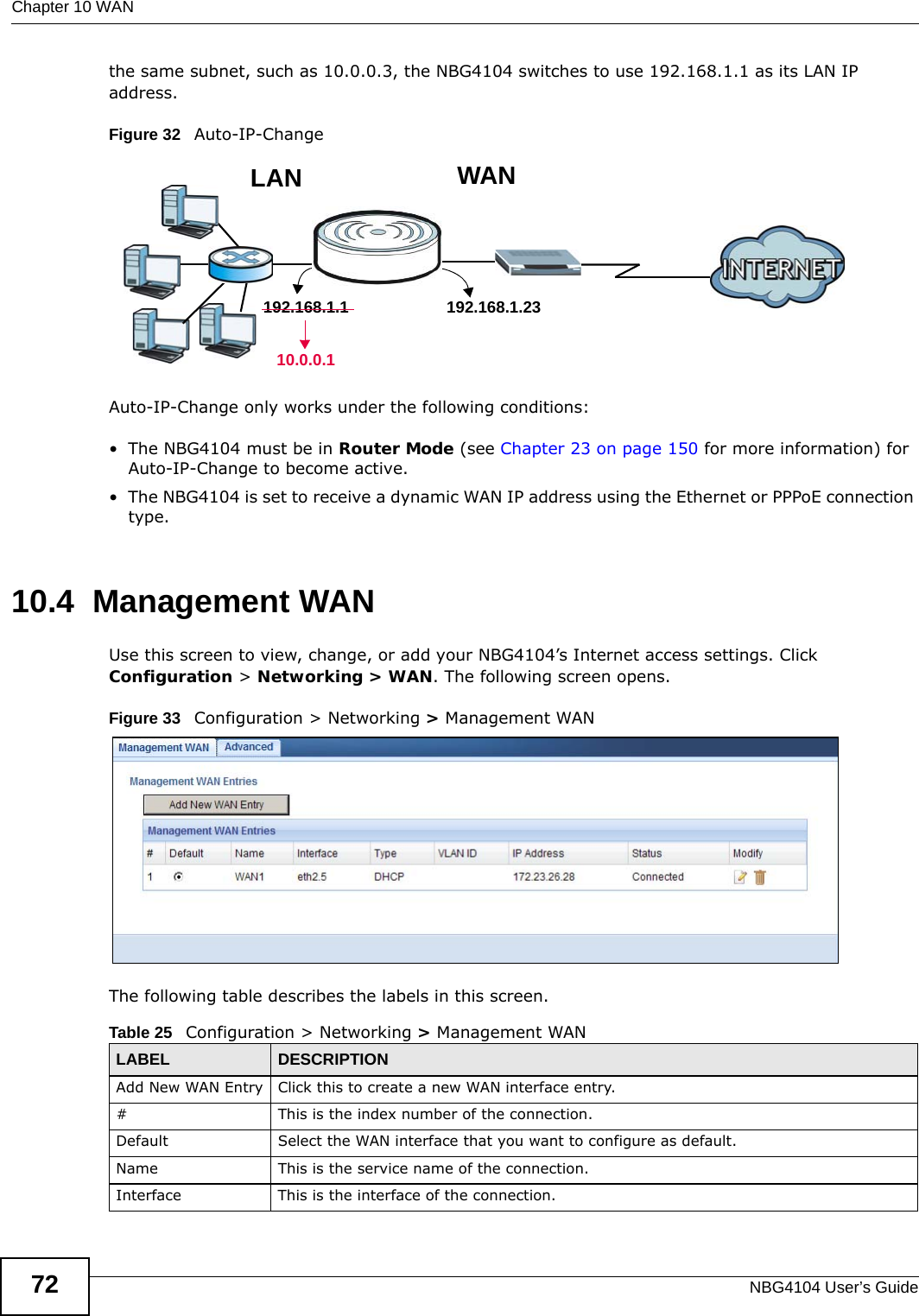
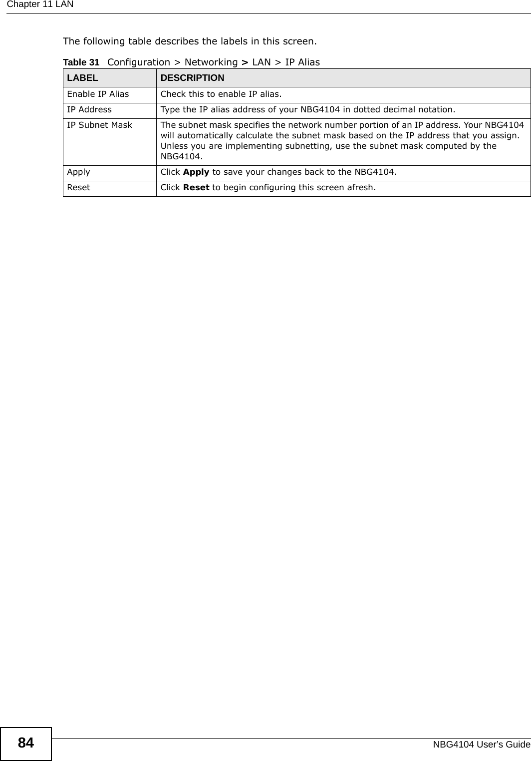
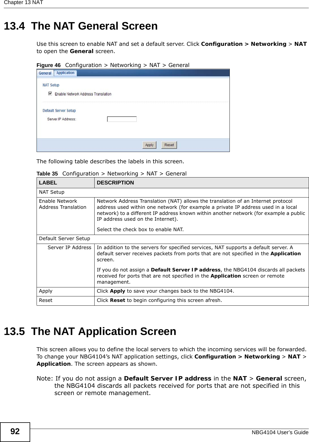

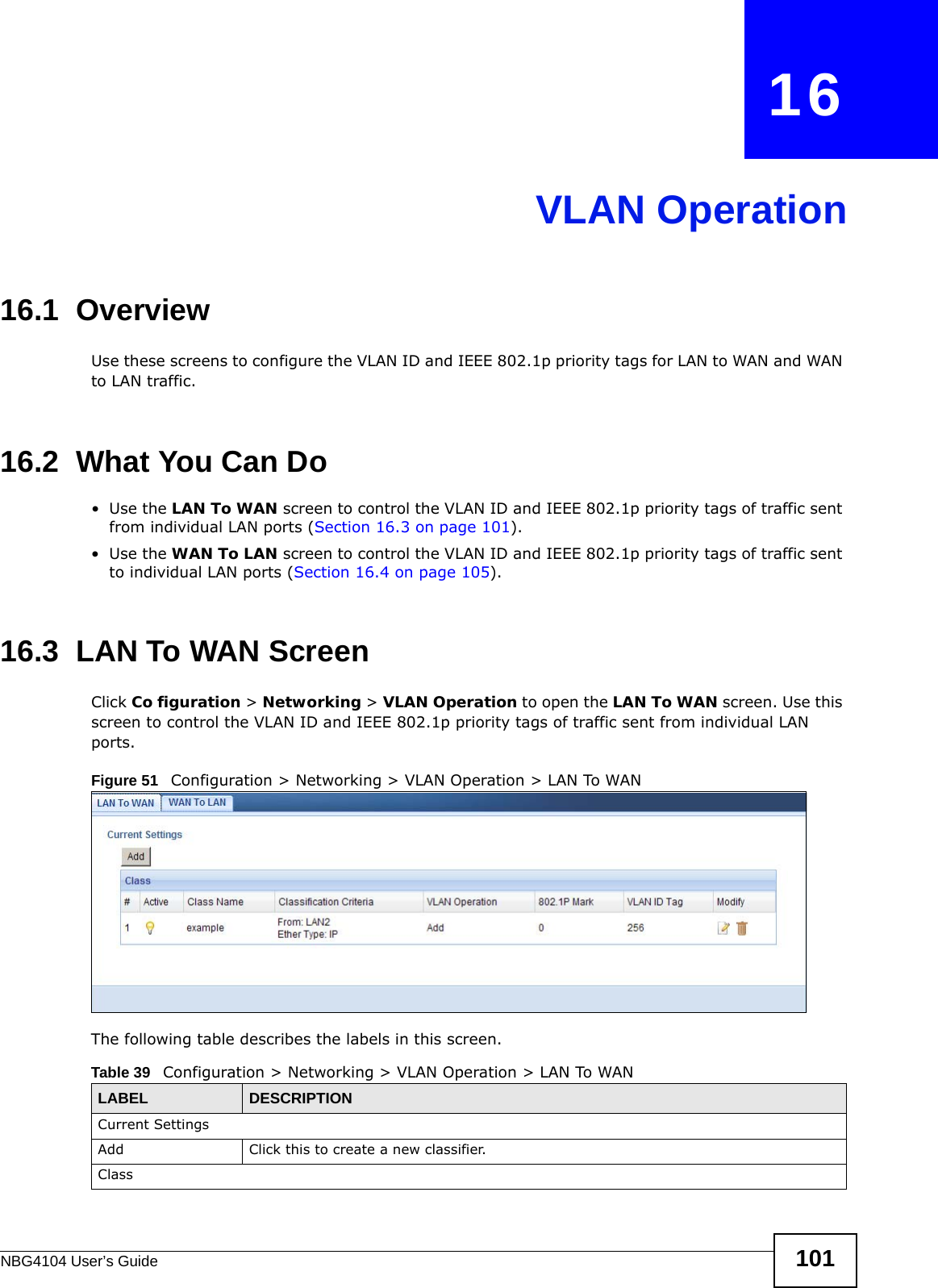

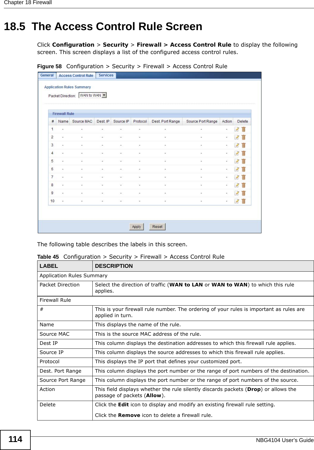

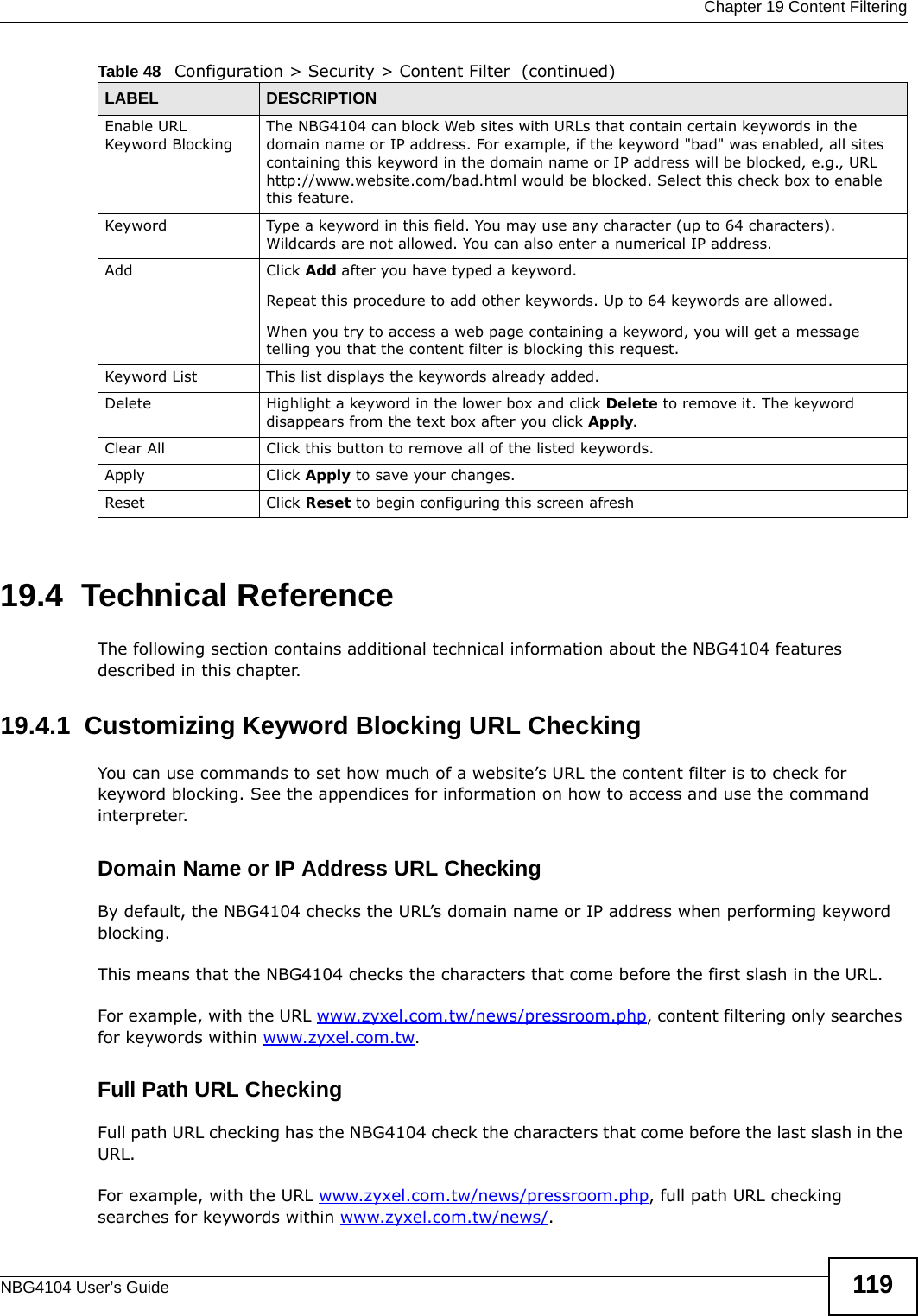
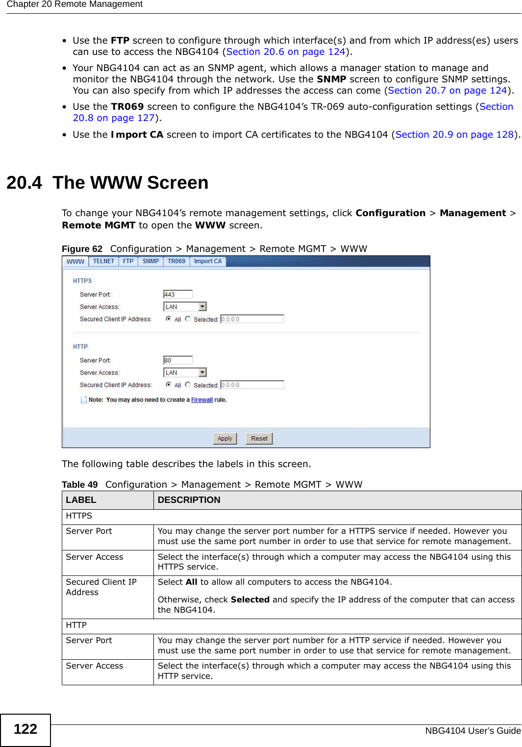
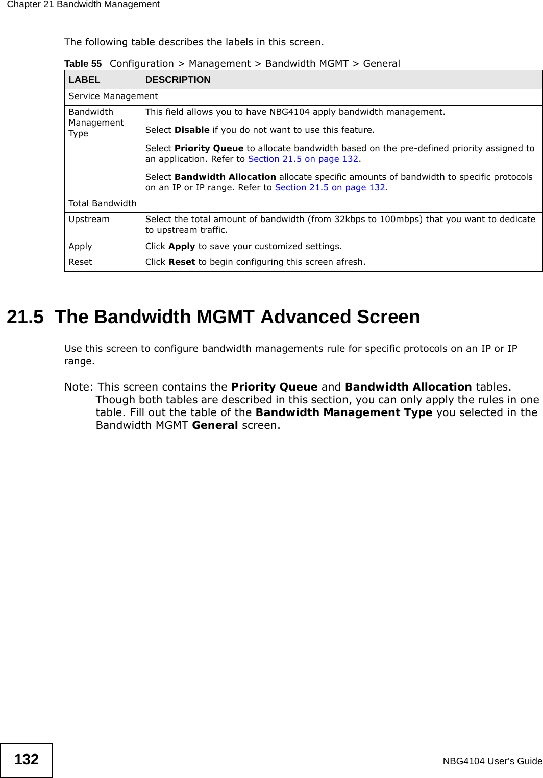
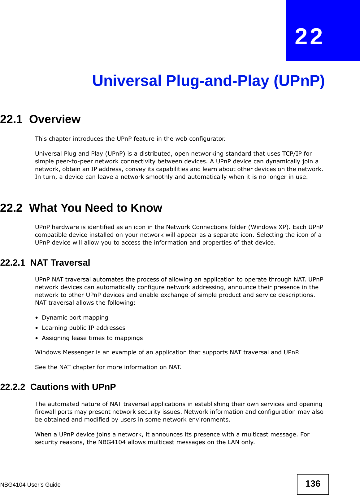
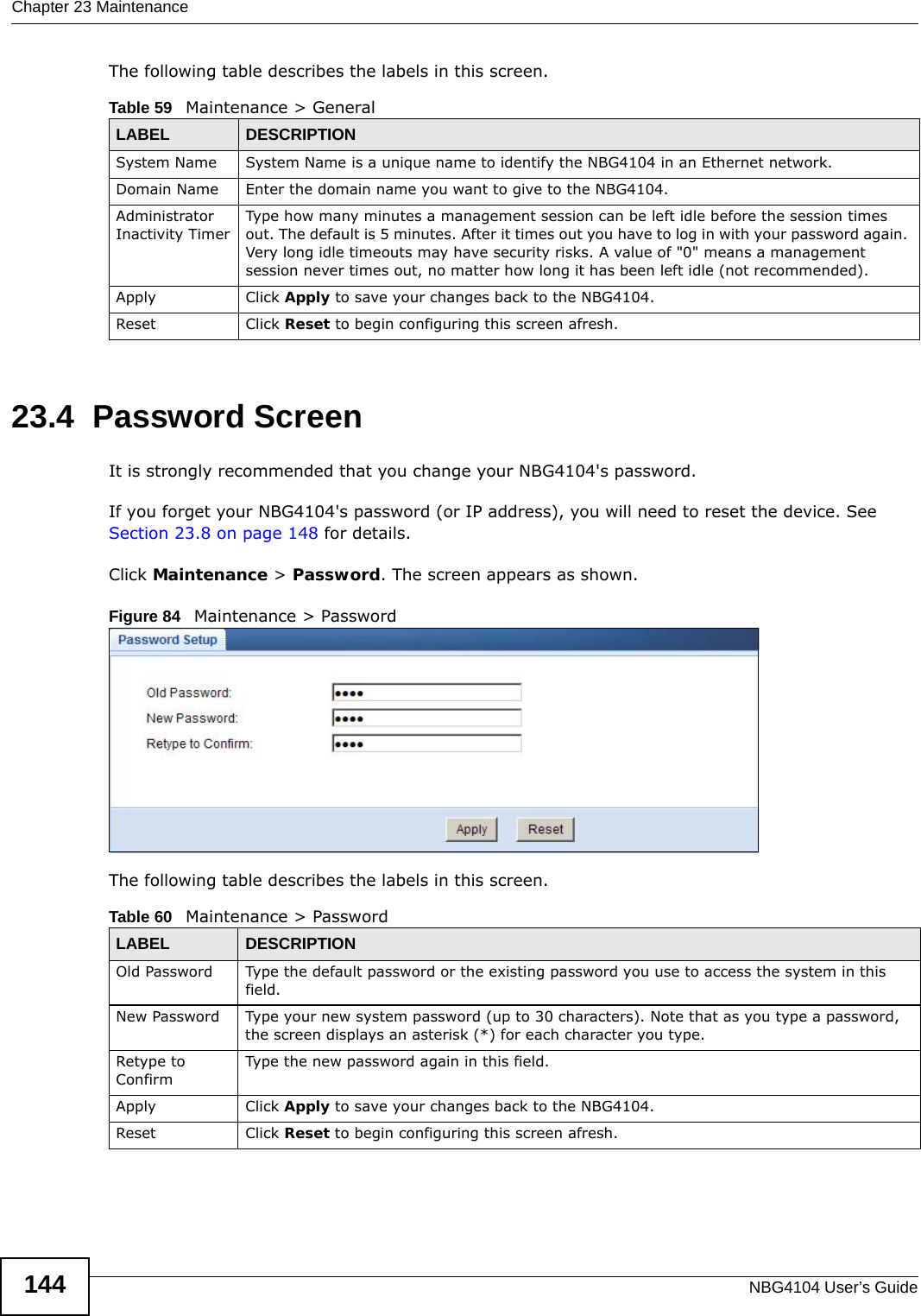
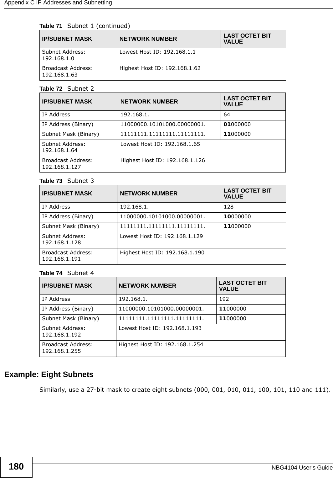
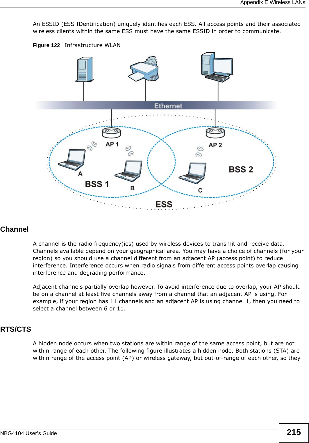
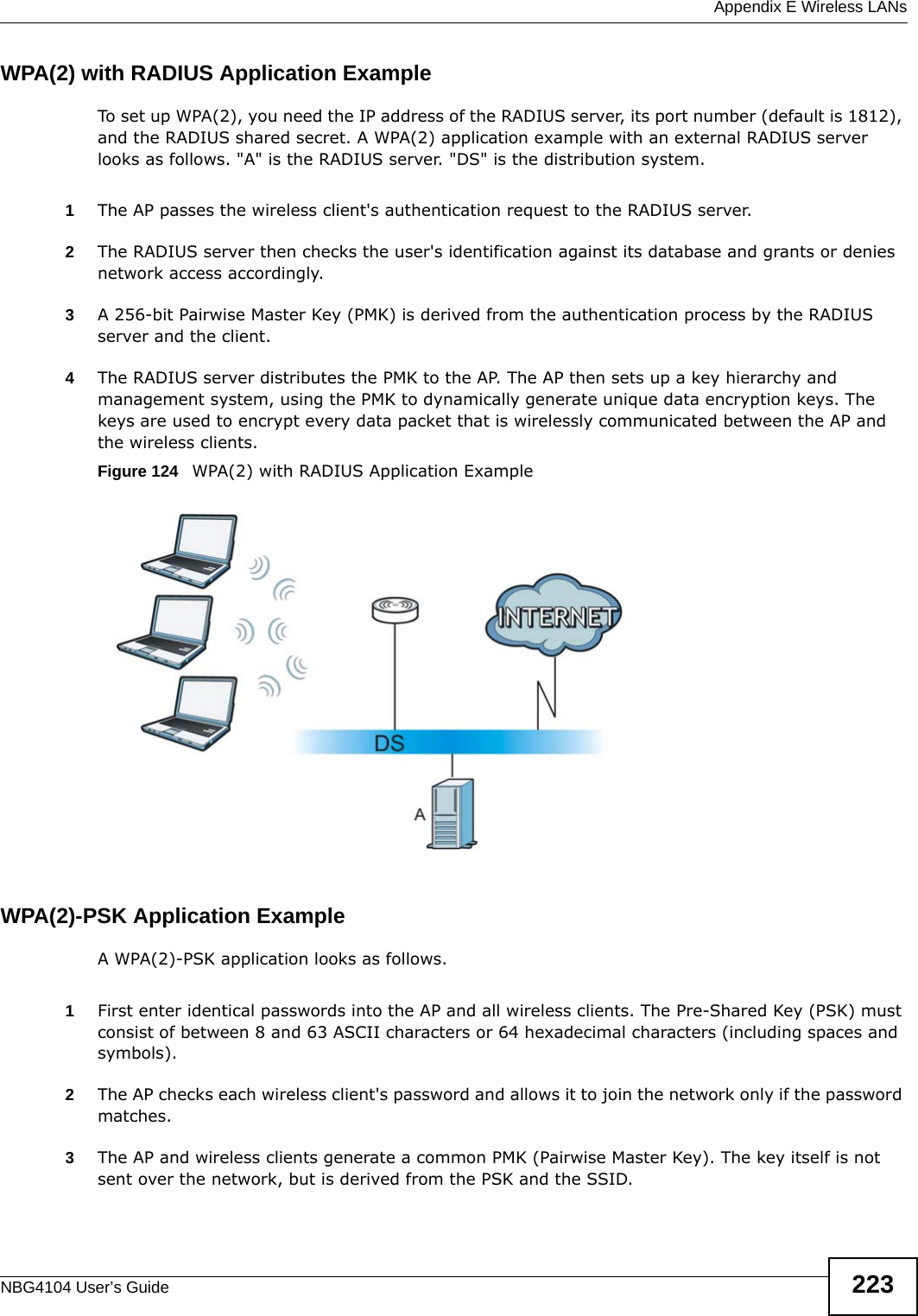
![Chapter 19 Content FilteringNBG4104 User’s Guide120Use the ip urlfilter customize actionFlags 6 [disable | enable] command to extend (or not extend) the keyword blocking search to include the URL's full path.File Name URL CheckingFilename URL checking has the NBG4104 check all of the characters in the URL.For example, filename URL checking searches for keywords within the URL www.zyxel.com.tw/news/pressroom.php.Use the ip urlfilter customize actionFlags 8 [disable | enable] command to extend (or not extend) the keyword blocking search to include the URL's complete filename.](https://usermanual.wiki/ZyXEL-Communications/NBG4104/User-Guide-1621838-Page-120.png)
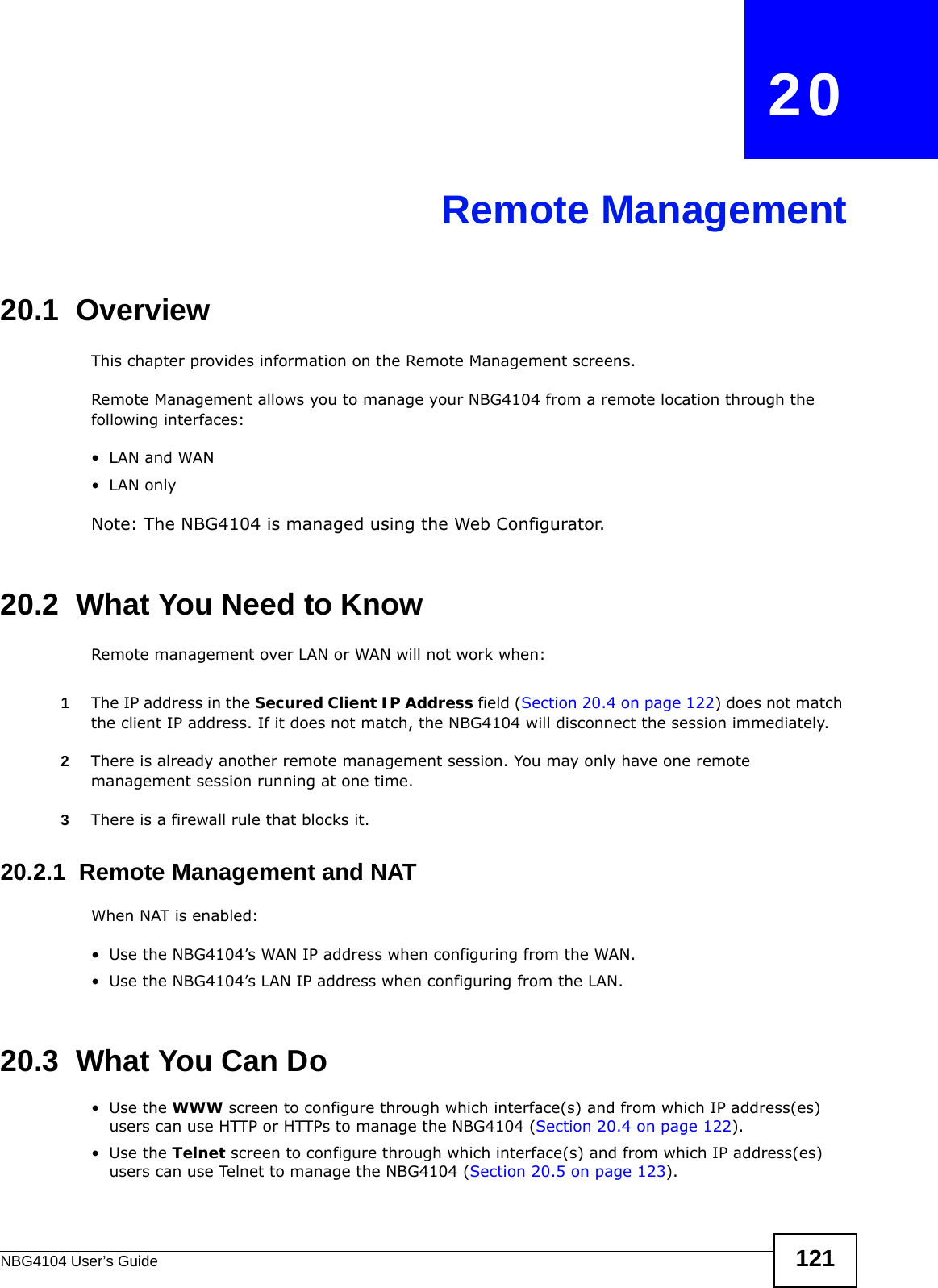
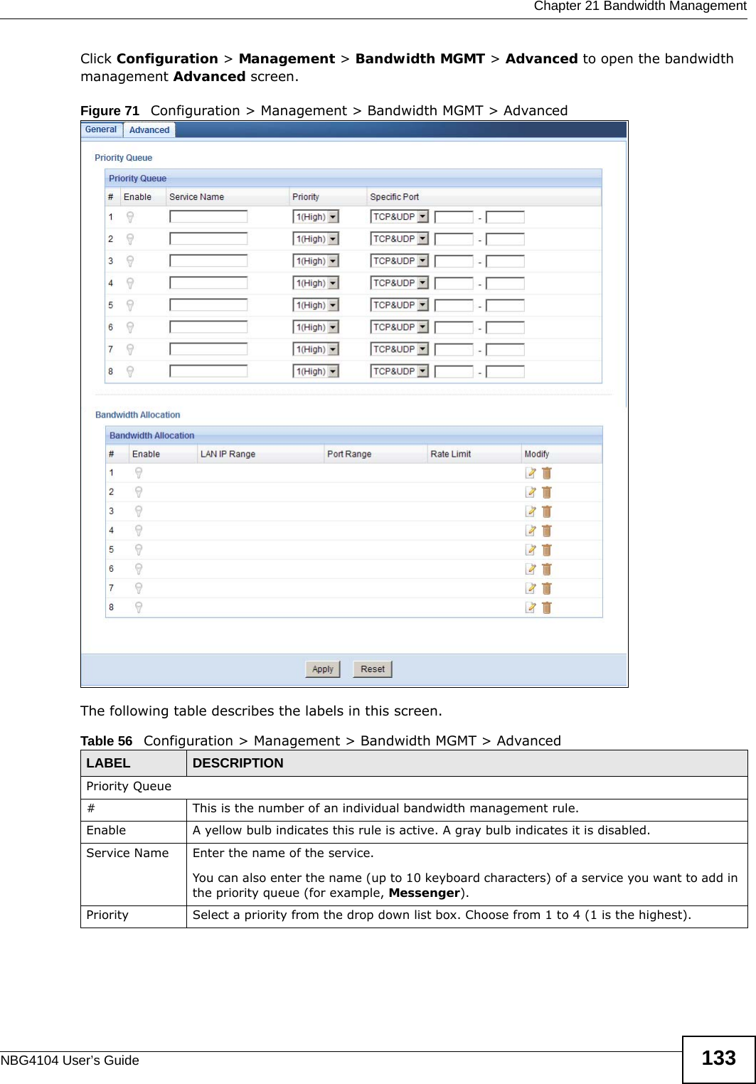
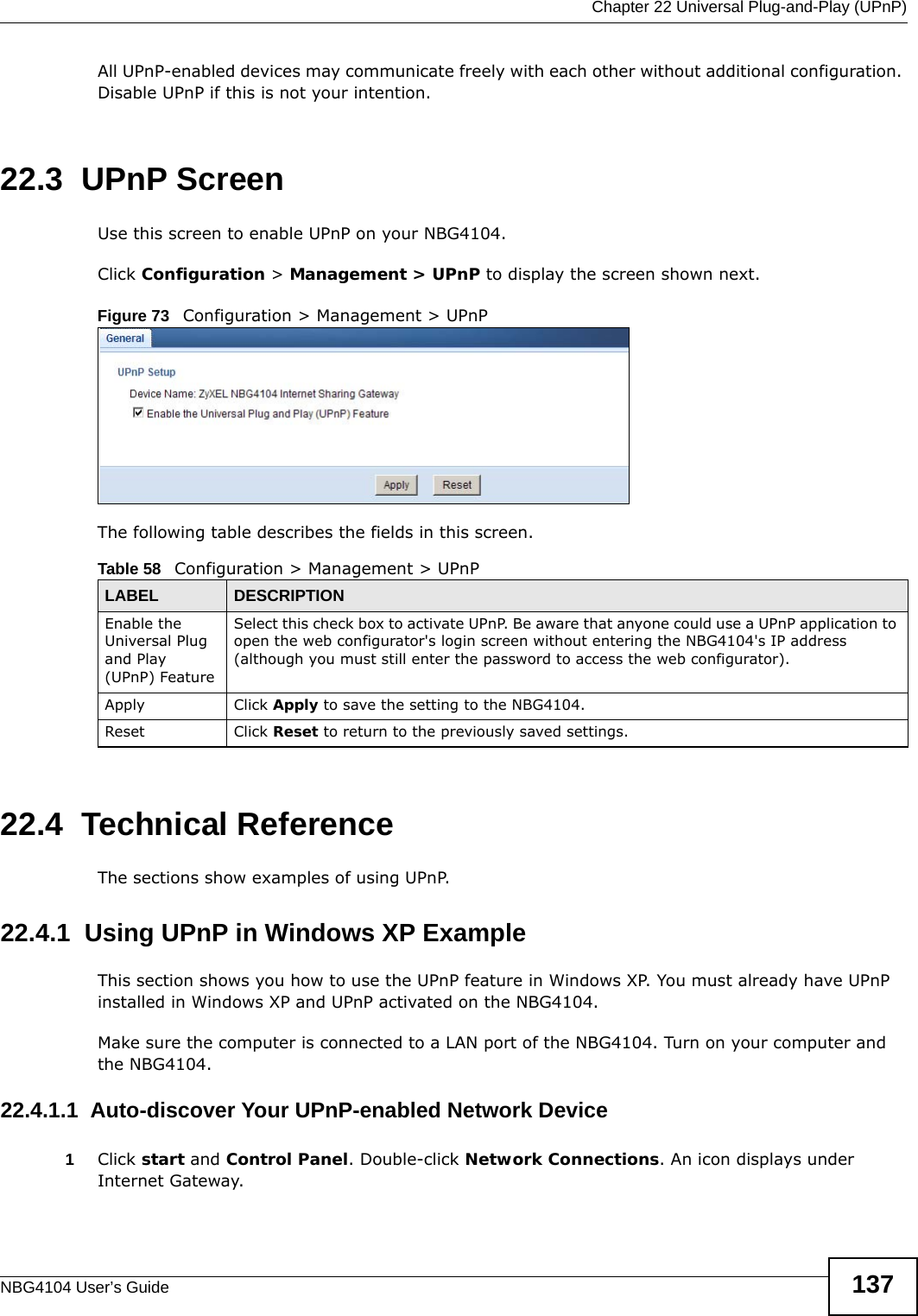
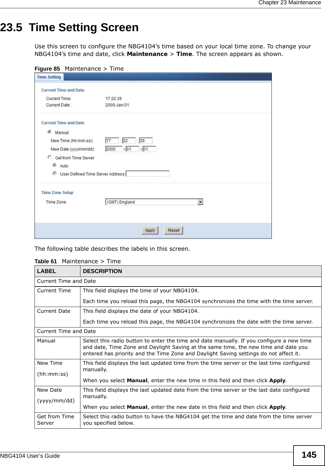
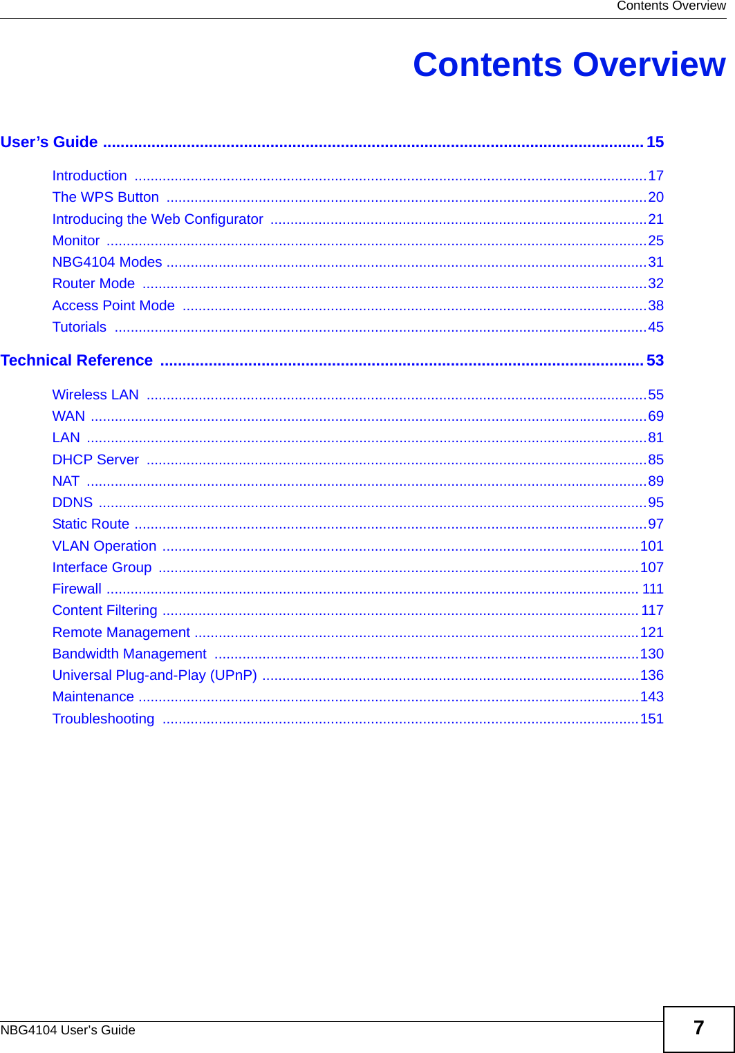
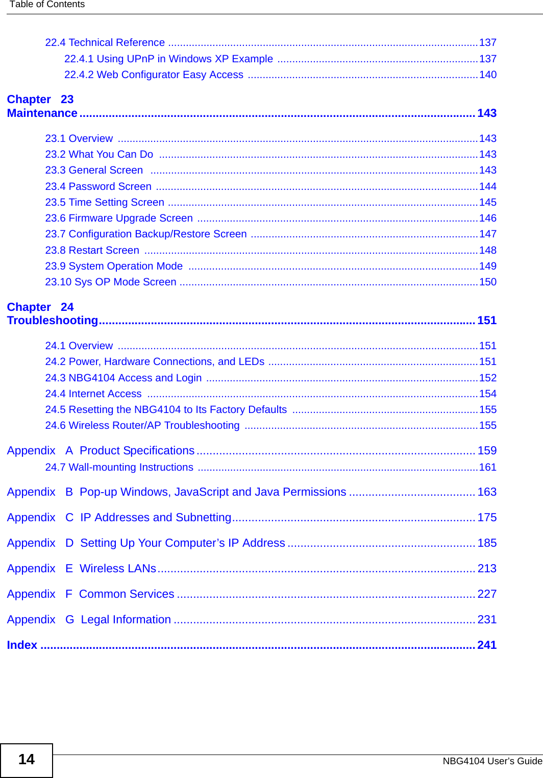
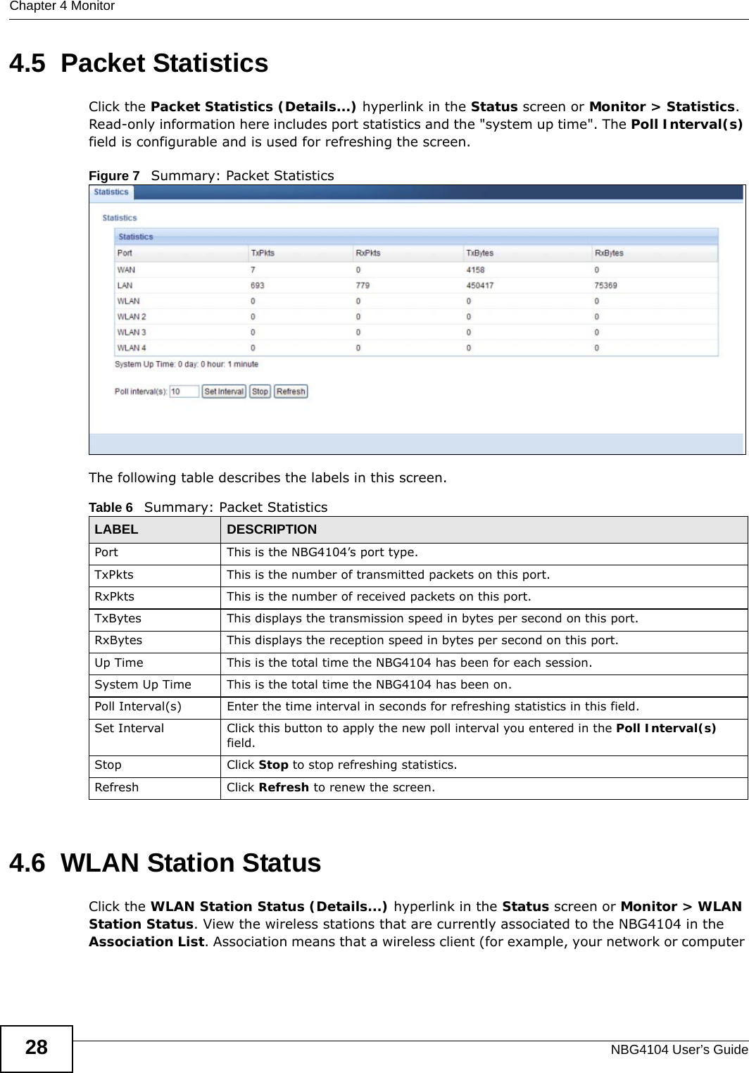
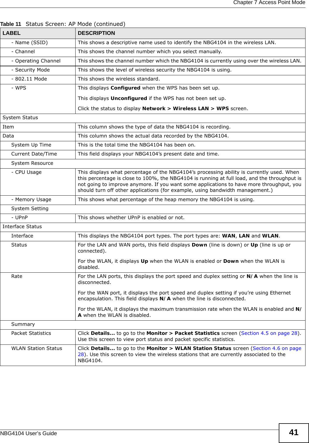
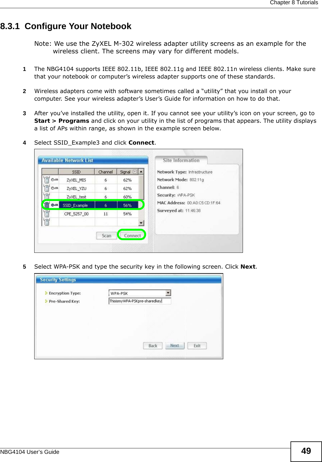
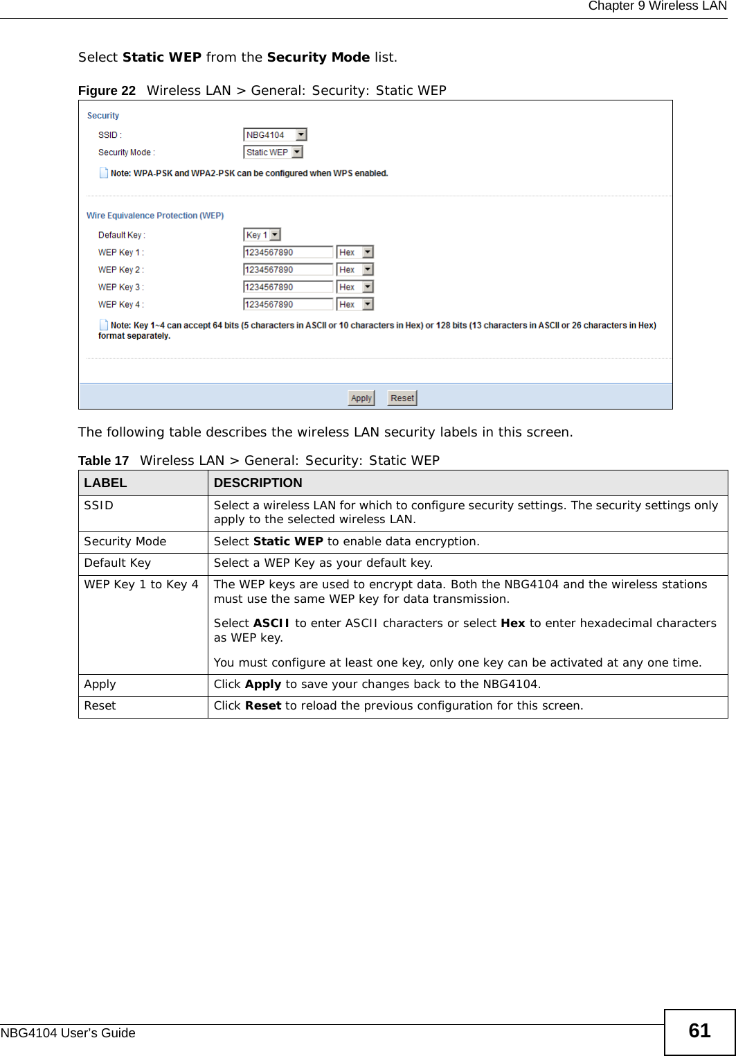
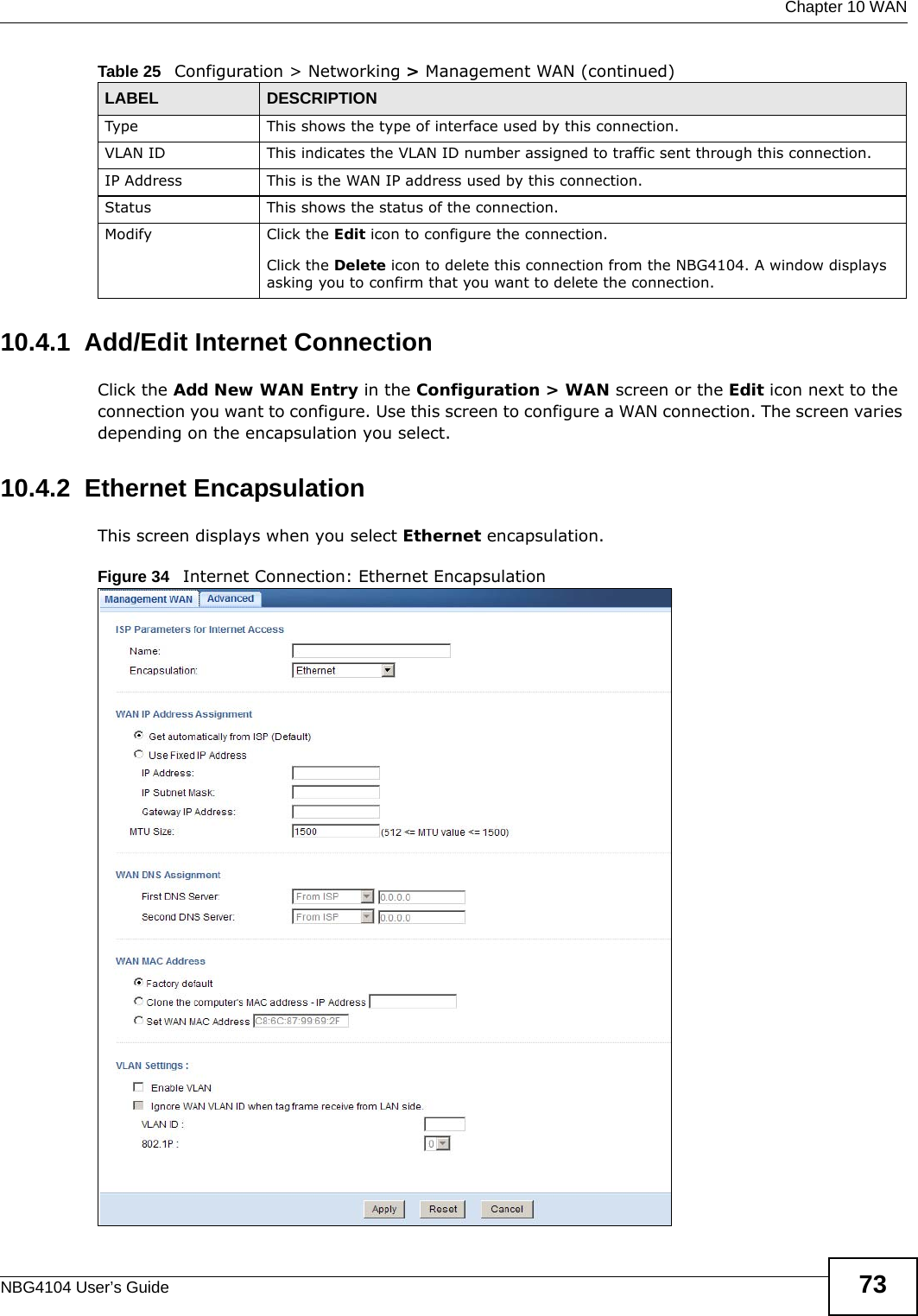
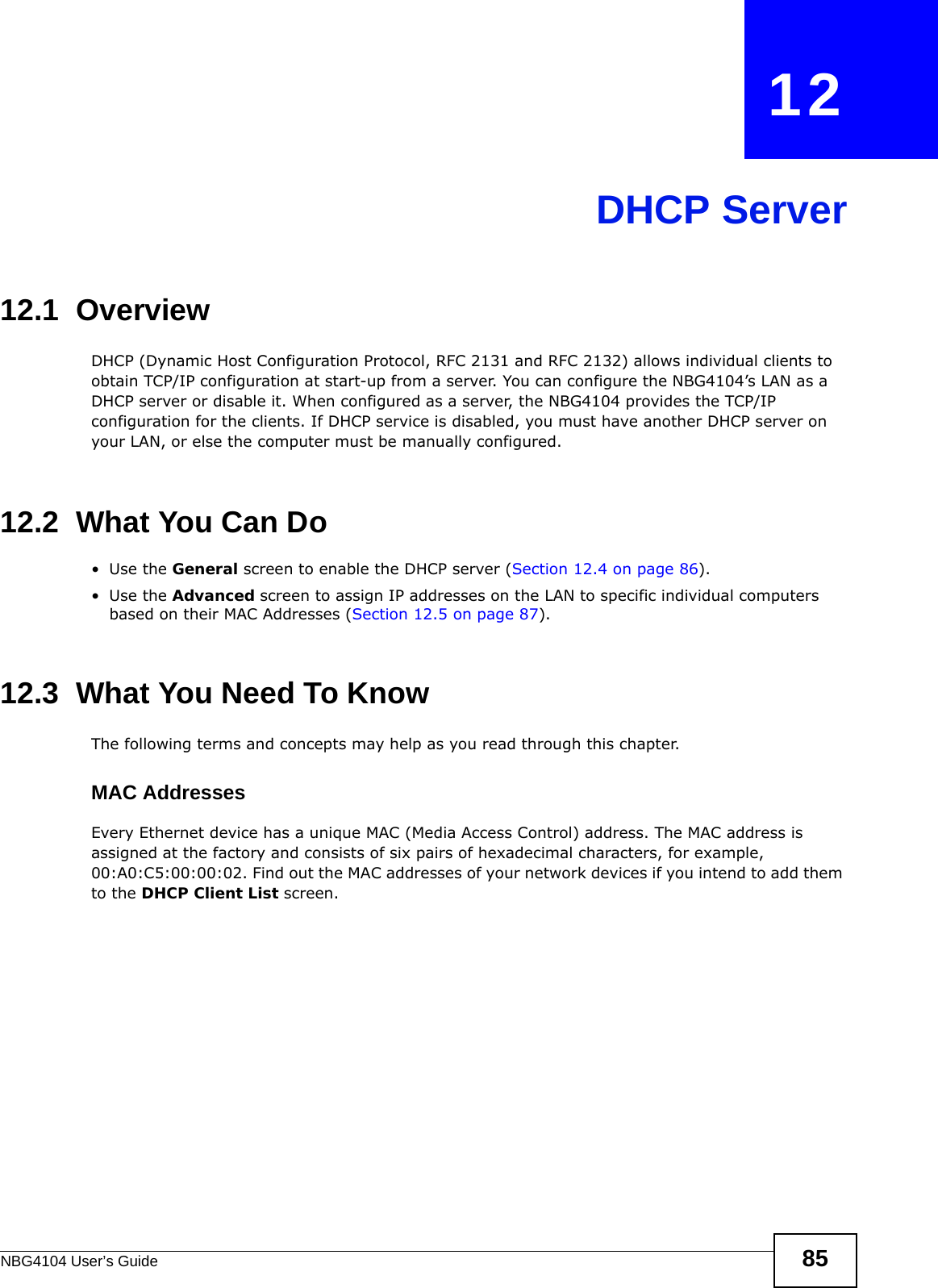
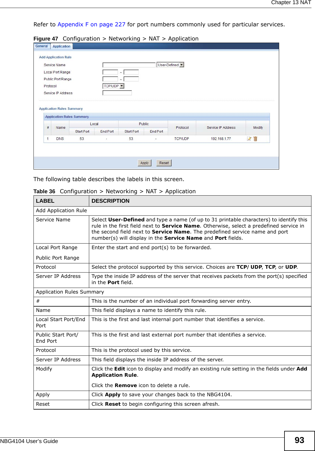
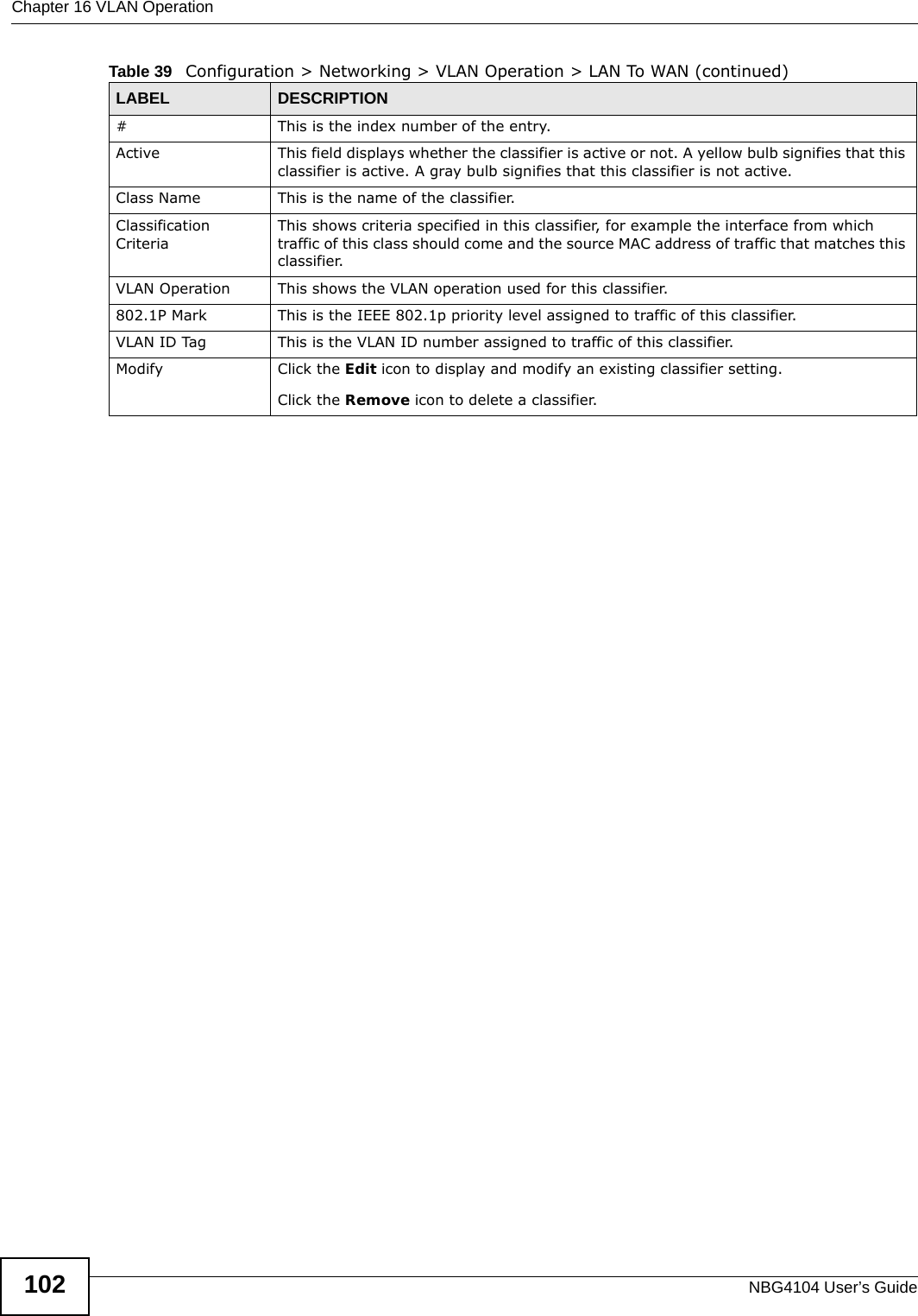
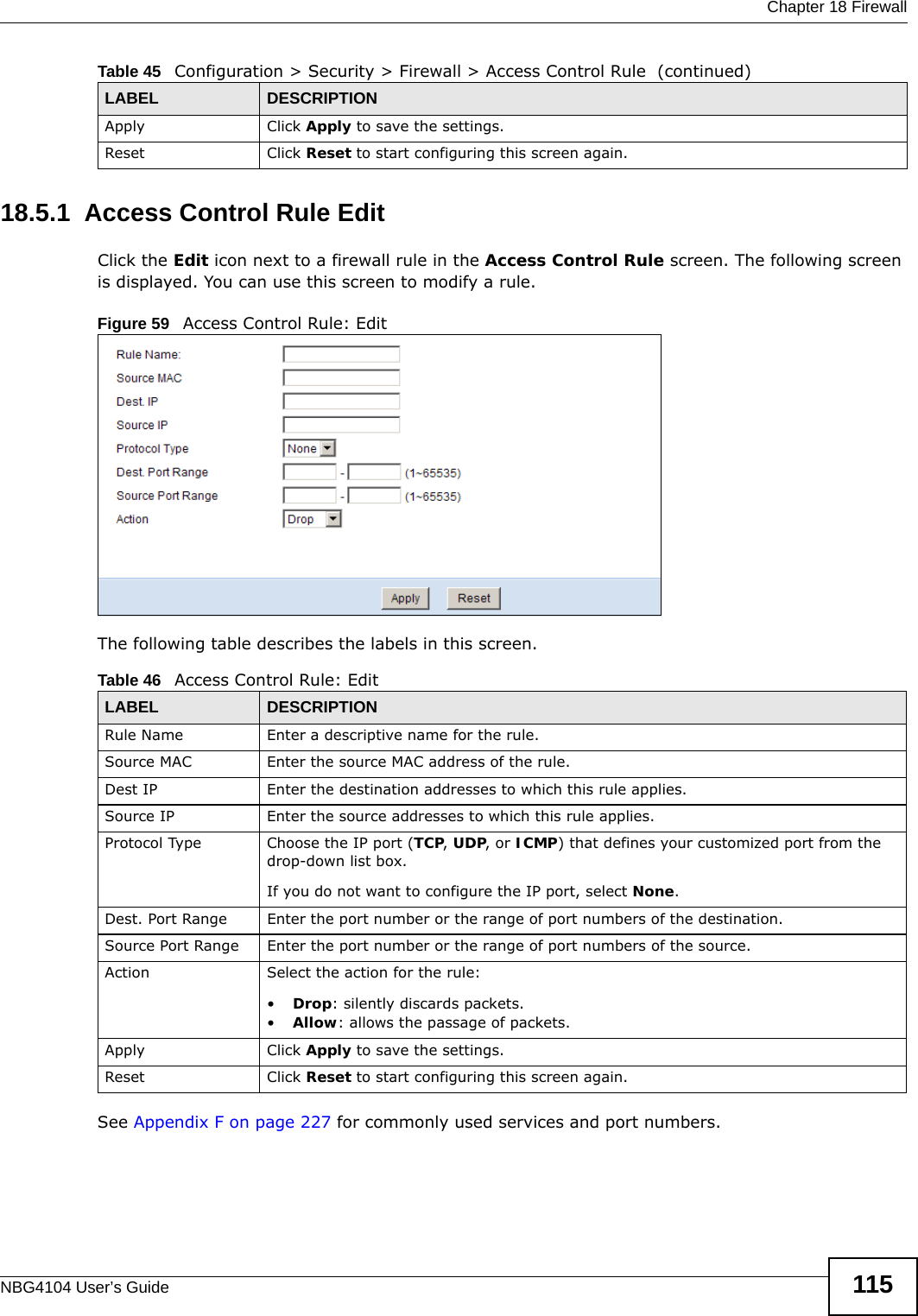
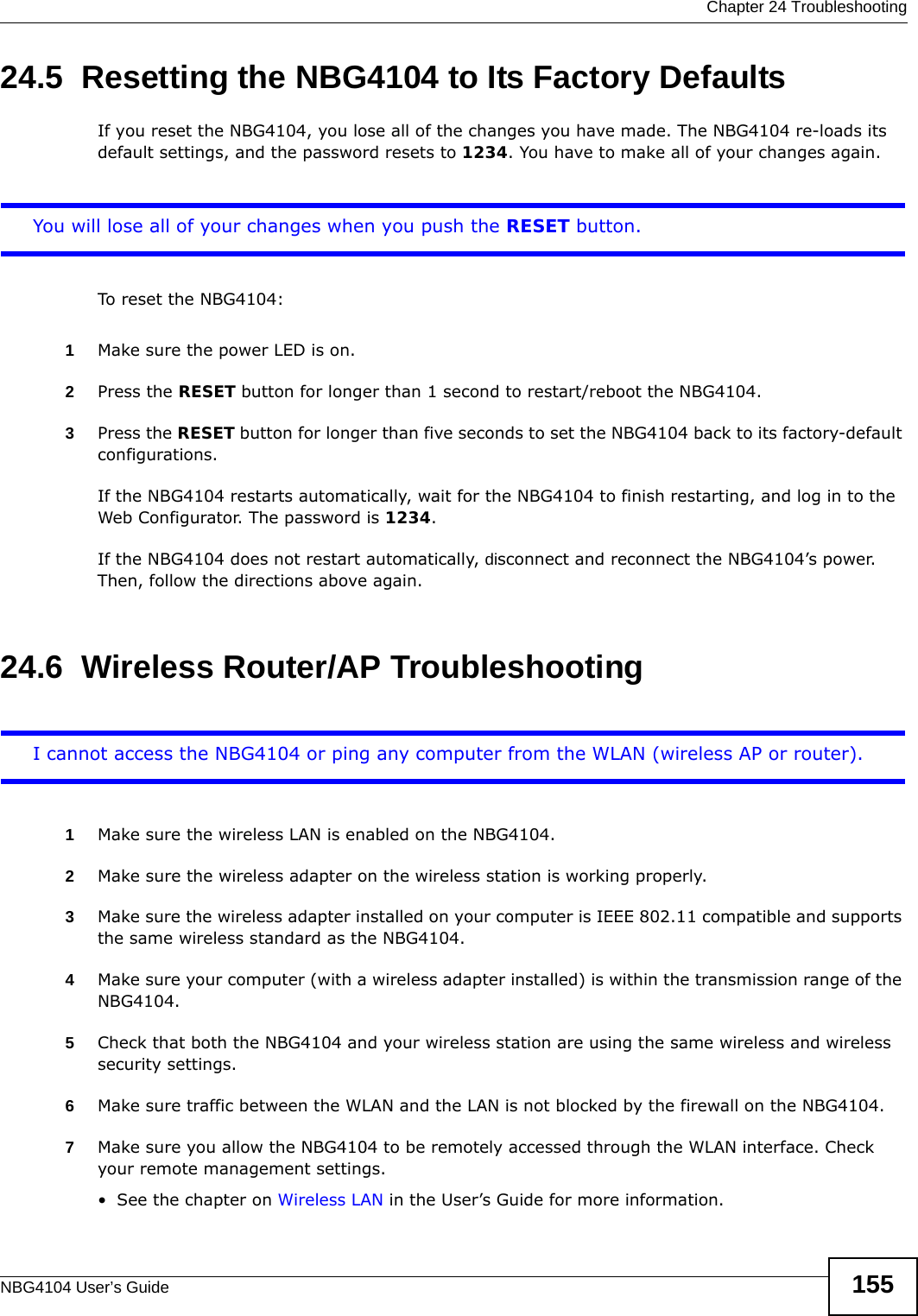
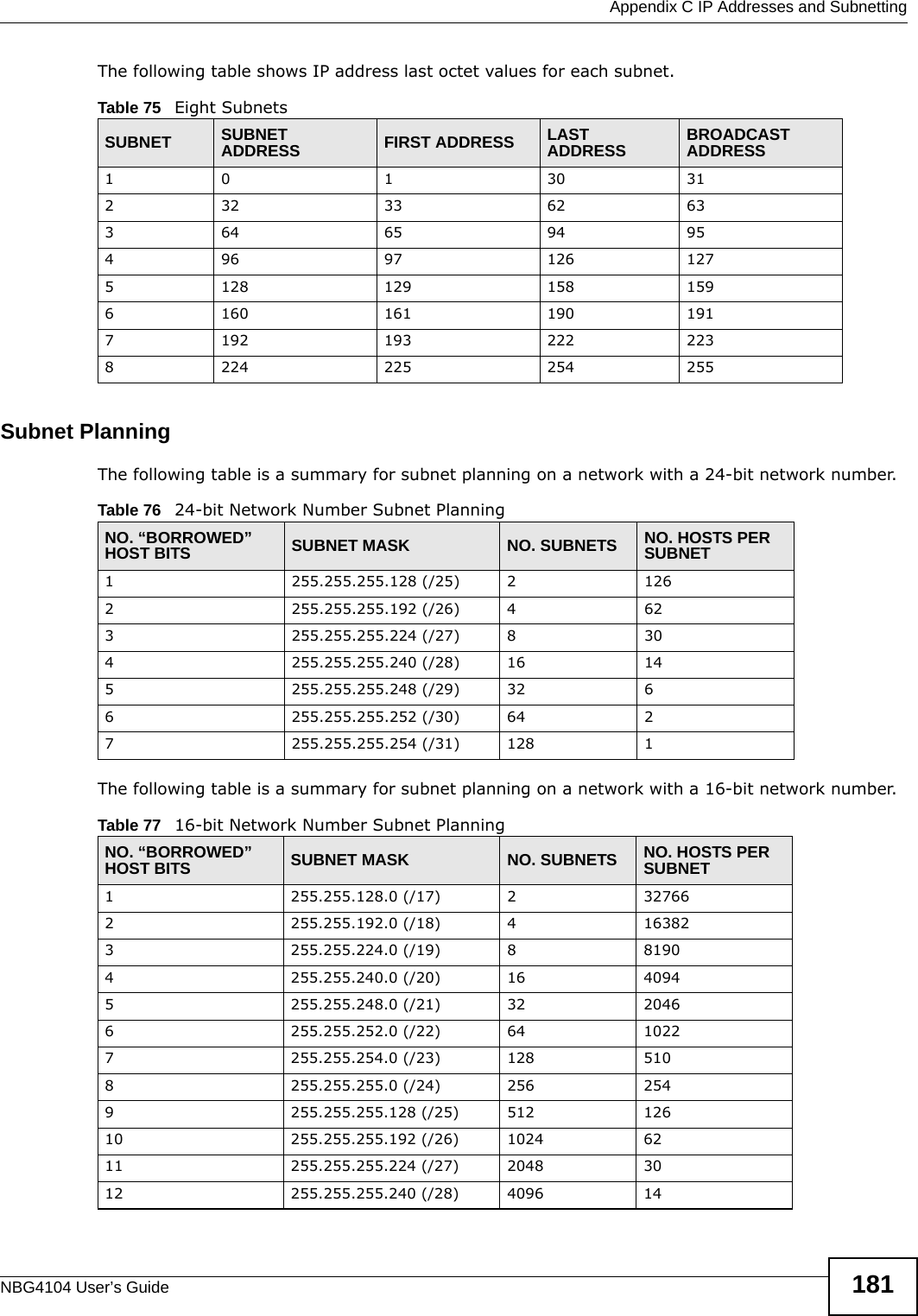
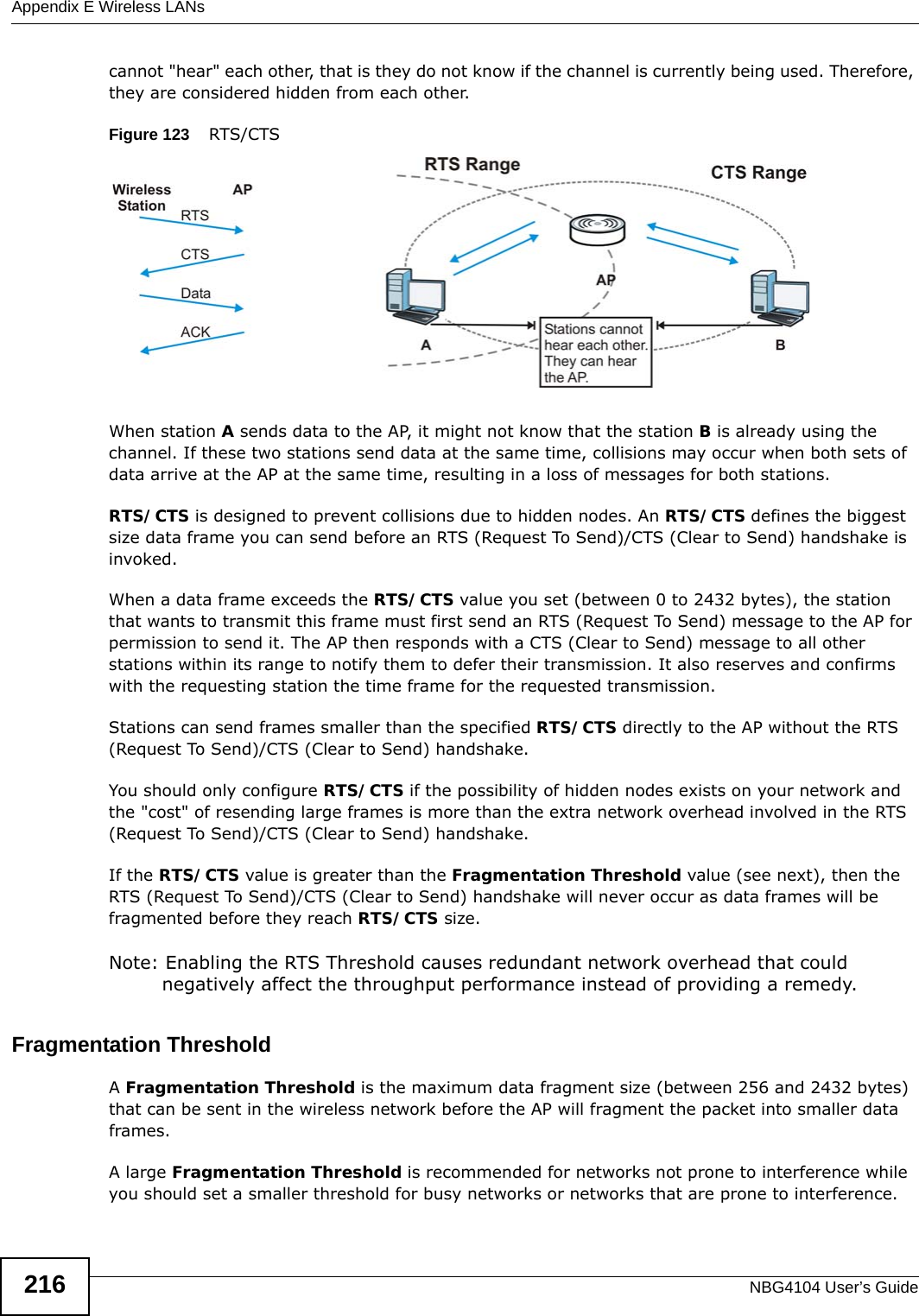
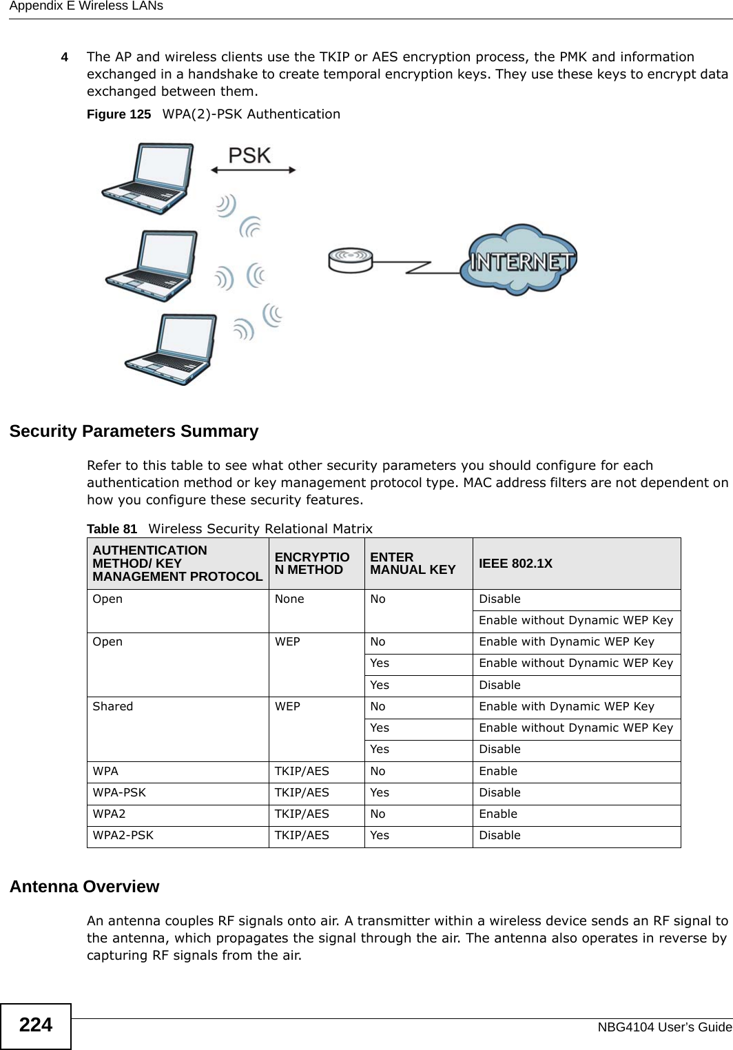
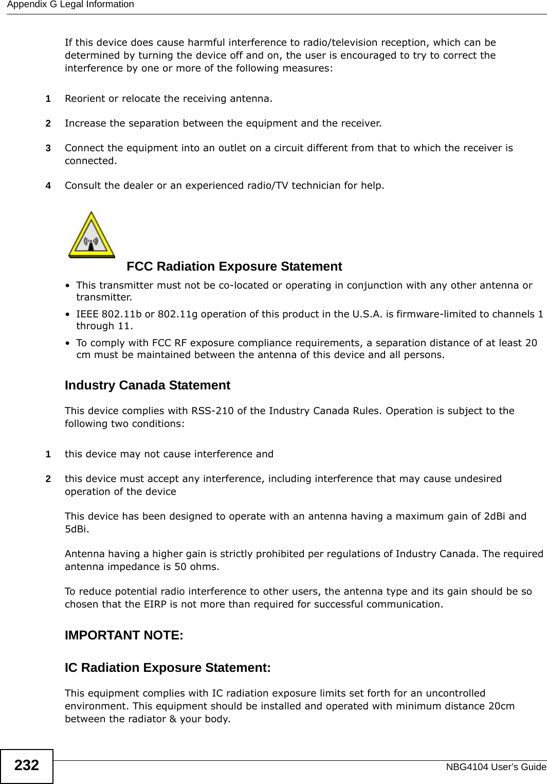
![Chapter 24 TroubleshootingNBG4104 User’s Guide 1532Check the hardware connections, and make sure the LEDs are behaving as expected. See the Quick Start Guide. 3Make sure your Internet browser does not block pop-up windows and has JavaScript and Java enabled. See Appendix B on page 163.4Make sure your computer is in the same subnet as the NBG4104. (If you know that there are routers between your computer and the NBG4104, skip this step.)• If there is a DHCP server on your network, make sure your computer is using a dynamic IP address. See Section 11.4 on page 83. • If there is no DHCP server on your network, make sure your computer’s IP address is in the same subnet as the NBG4104. See Section 11.4 on page 83.5Reset the device to its factory defaults, and try to access the NBG4104 with the default IP address. See Section 3.3.1 on page 23.6If the problem continues, contact the network administrator or vendor, or try one of the advanced suggestions.Advanced Suggestions• Try to access the NBG4104 using another service, such as Telnet. If you can access the NBG4104, check the remote management settings and firewall rules to find out why the NBG4104 does not respond to HTTP.• If your computer is connected to the WAN port or is connected wirelessly, use a computer that is connected to a LAN/ETHERNET port.I can see the Login screen, but I cannot log in to the NBG4104.1Make sure you have entered the password correctly. The default password is 1234. This field is case-sensitive, so make sure [Caps Lock] is not on. 2You cannot log in to the Web Configurator while someone is using Telnet to access the NBG4104. Log out of the NBG4104 in the other session, or ask the person who is logged in to log out. 3This can happen when you fail to log out properly from your last session. Try logging in again after 5 minutes.4Disconnect and re-connect the power adaptor or cord to the NBG4104. 5If this does not work, you have to reset the device to its factory defaults. See Section 24.5 on page 155.](https://usermanual.wiki/ZyXEL-Communications/NBG4104/User-Guide-1621838-Page-153.png)
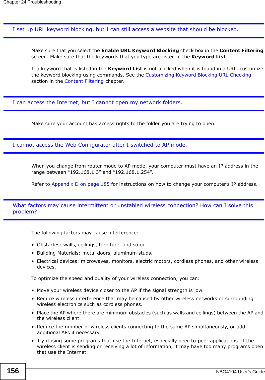


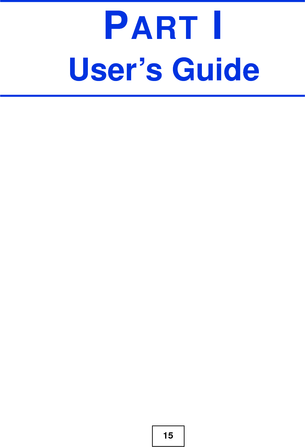
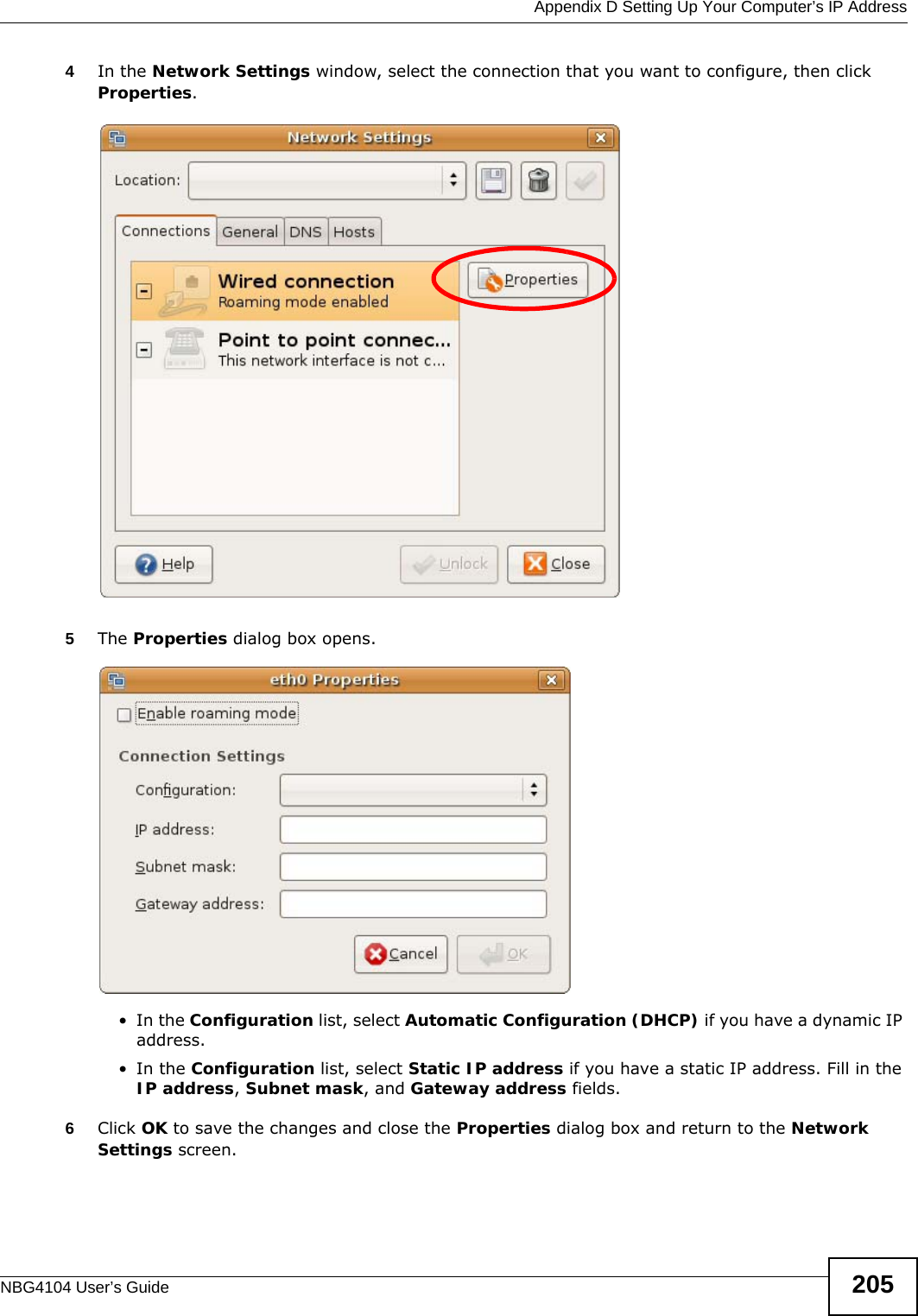
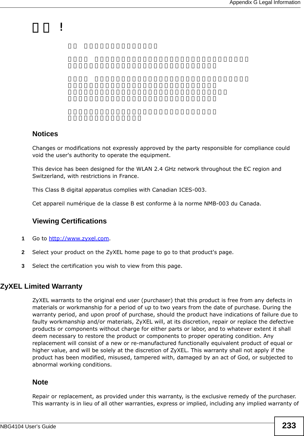
![Appendix D Setting Up Your Computer’s IP AddressNBG4104 User’s Guide1885The Internet Protocol TCP/IP Properties window opens.6Select Obtain an IP address automatically if your network administrator or ISP assigns your IP address dynamically.Select Use the following IP Address and fill in the IP address, Subnet mask, and Default gateway fields if you have a static IP address that was assigned to you by your network administrator or ISP. You may also have to enter a Preferred DNS server and an Alternate DNS server, if that information was provided.7Click OK to close the Internet Protocol (TCP/IP) Properties window.8Click OK to close the Local Area Connection Properties window.Verifying Settings1Click Start > All Programs > Accessories > Command Prompt.2In the Command Prompt window, type "ipconfig" and then press [ENTER]. You can also go to Start > Control Panel > Network Connections, right-click a network connection, click Status and then click the Support tab to view your IP address and connection information.](https://usermanual.wiki/ZyXEL-Communications/NBG4104/User-Guide-1621838-Page-188.png)
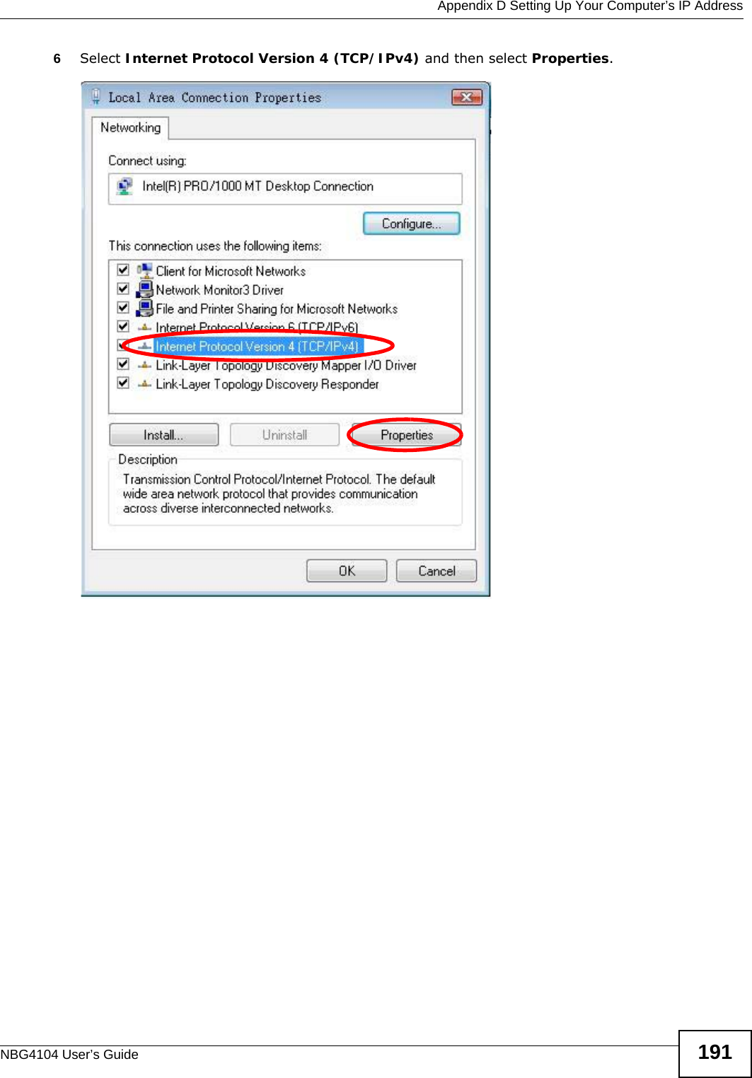
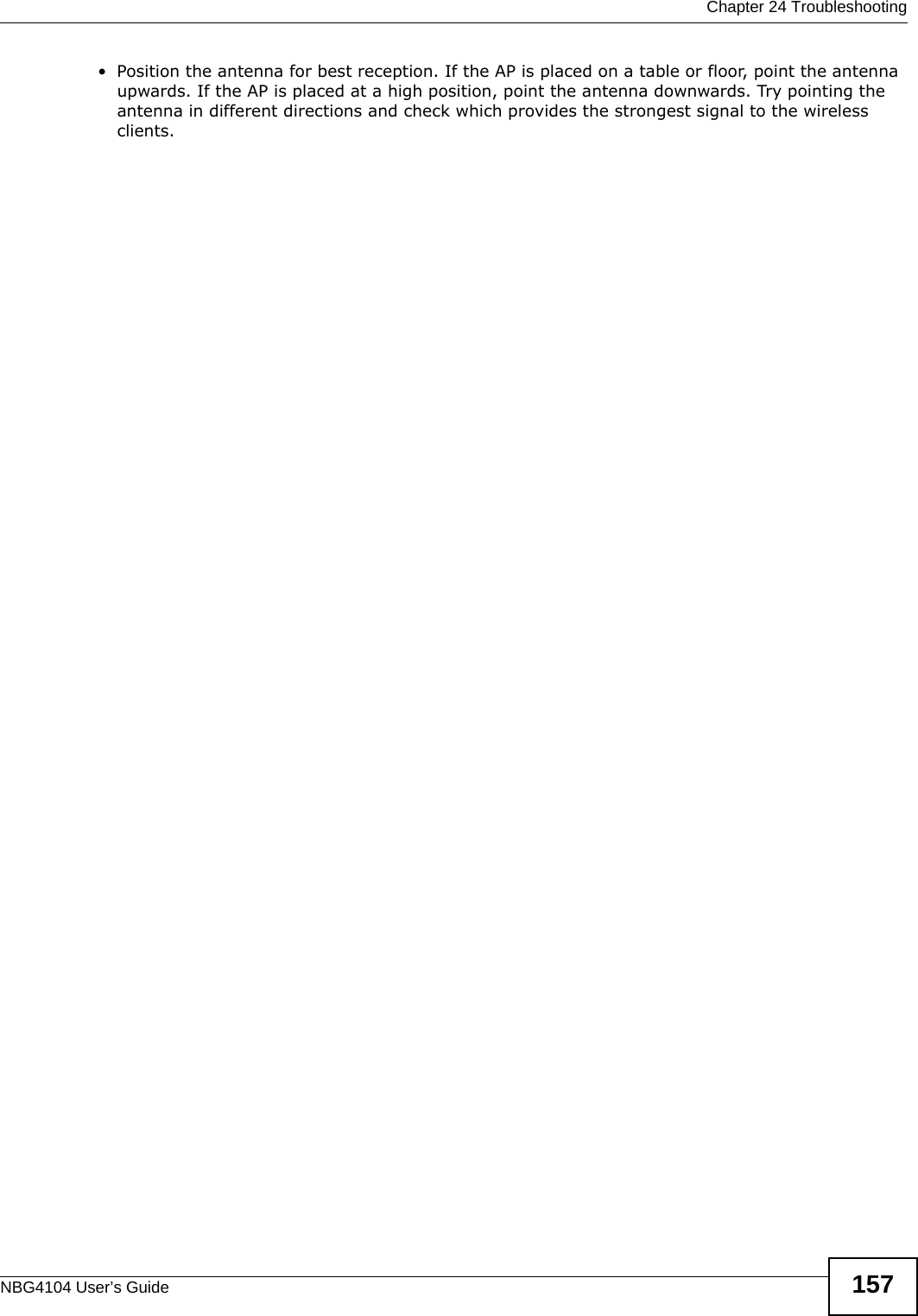
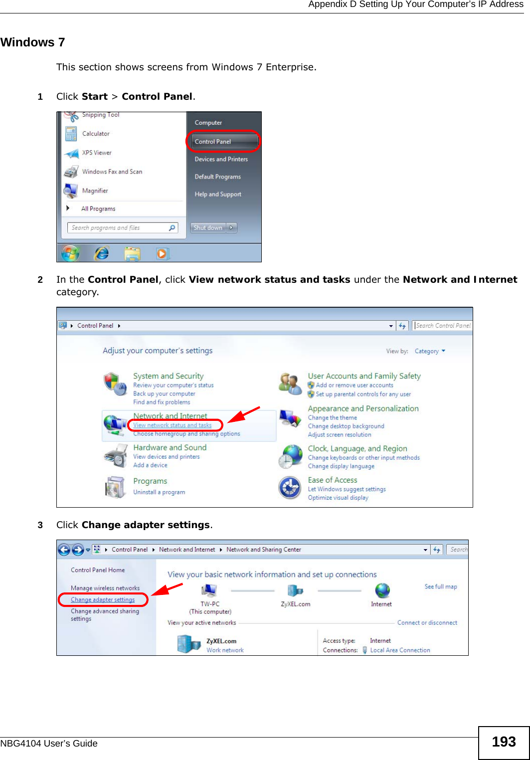
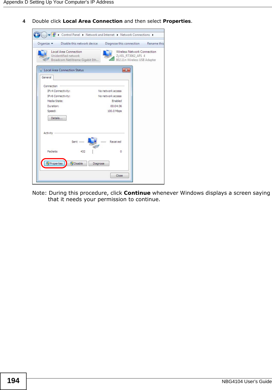
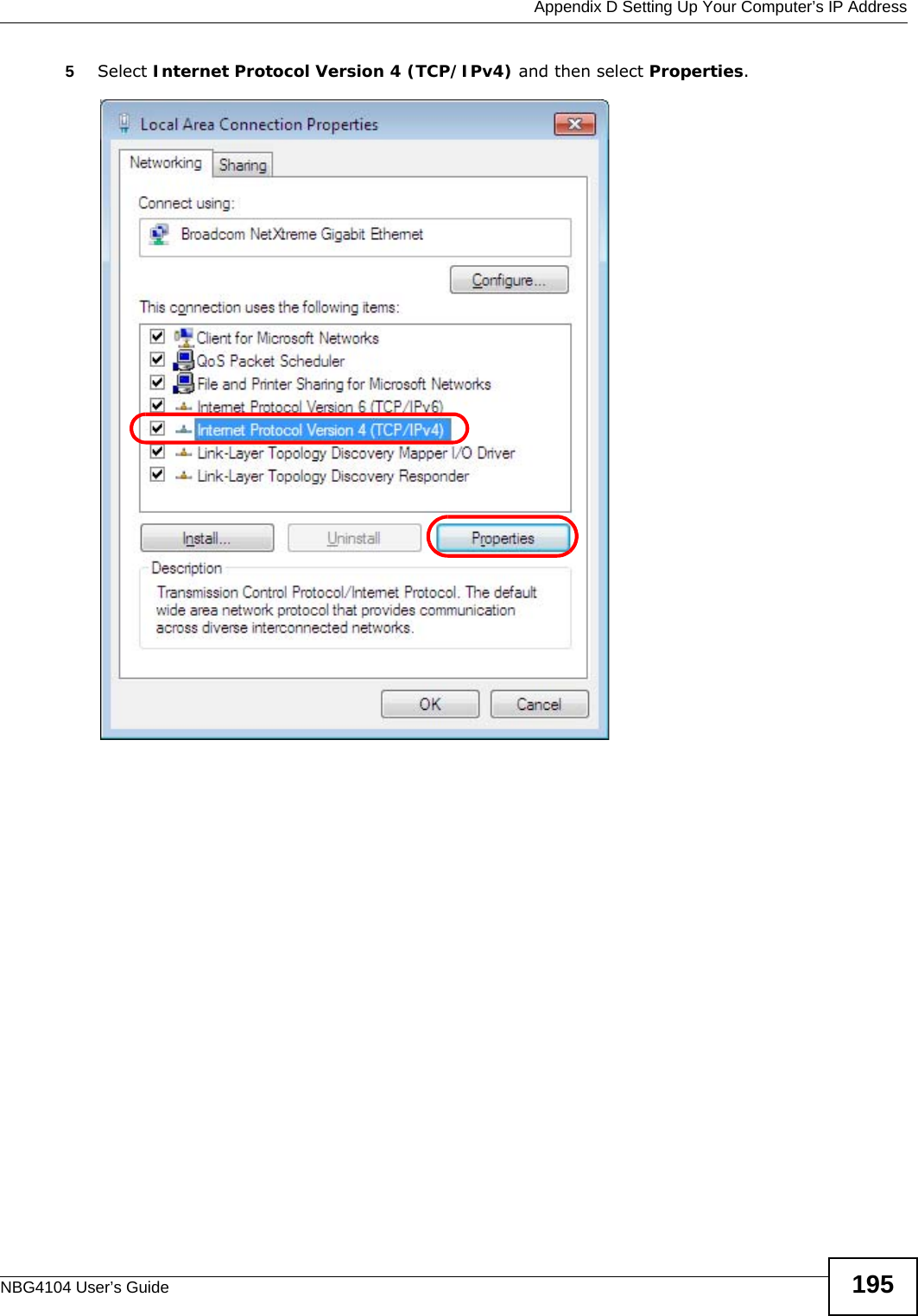
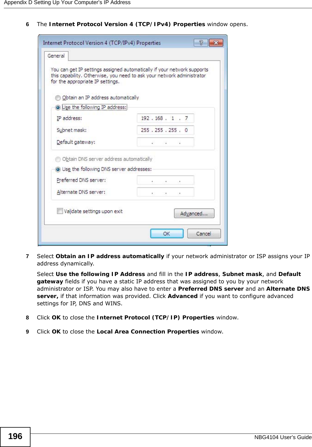
![Appendix D Setting Up Your Computer’s IP AddressNBG4104 User’s Guide1927The Internet Protocol Version 4 (TCP/IPv4) Properties window opens.8Select Obtain an IP address automatically if your network administrator or ISP assigns your IP address dynamically.Select Use the following IP Address and fill in the IP address, Subnet mask, and Default gateway fields if you have a static IP address that was assigned to you by your network administrator or ISP. You may also have to enter a Preferred DNS server and an Alternate DNS server, if that information was provided.Click Advanced.9Click OK to close the Internet Protocol (TCP/IP) Properties window.10 Click OK to close the Local Area Connection Properties window.Verifying Settings1Click Start > All Programs > Accessories > Command Prompt.2In the Command Prompt window, type "ipconfig" and then press [ENTER]. You can also go to Start > Control Panel > Network Connections, right-click a network connection, click Status and then click the Support tab to view your IP address and connection information.](https://usermanual.wiki/ZyXEL-Communications/NBG4104/User-Guide-1621838-Page-192.png)
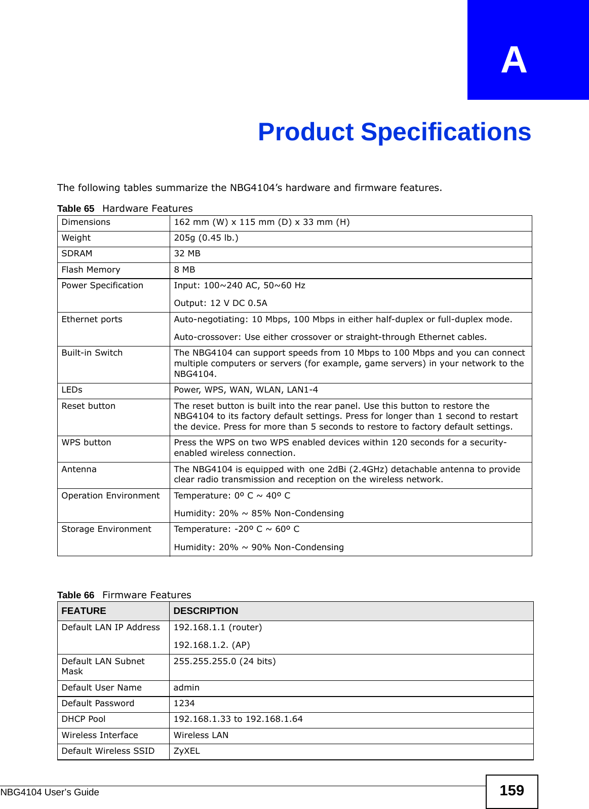
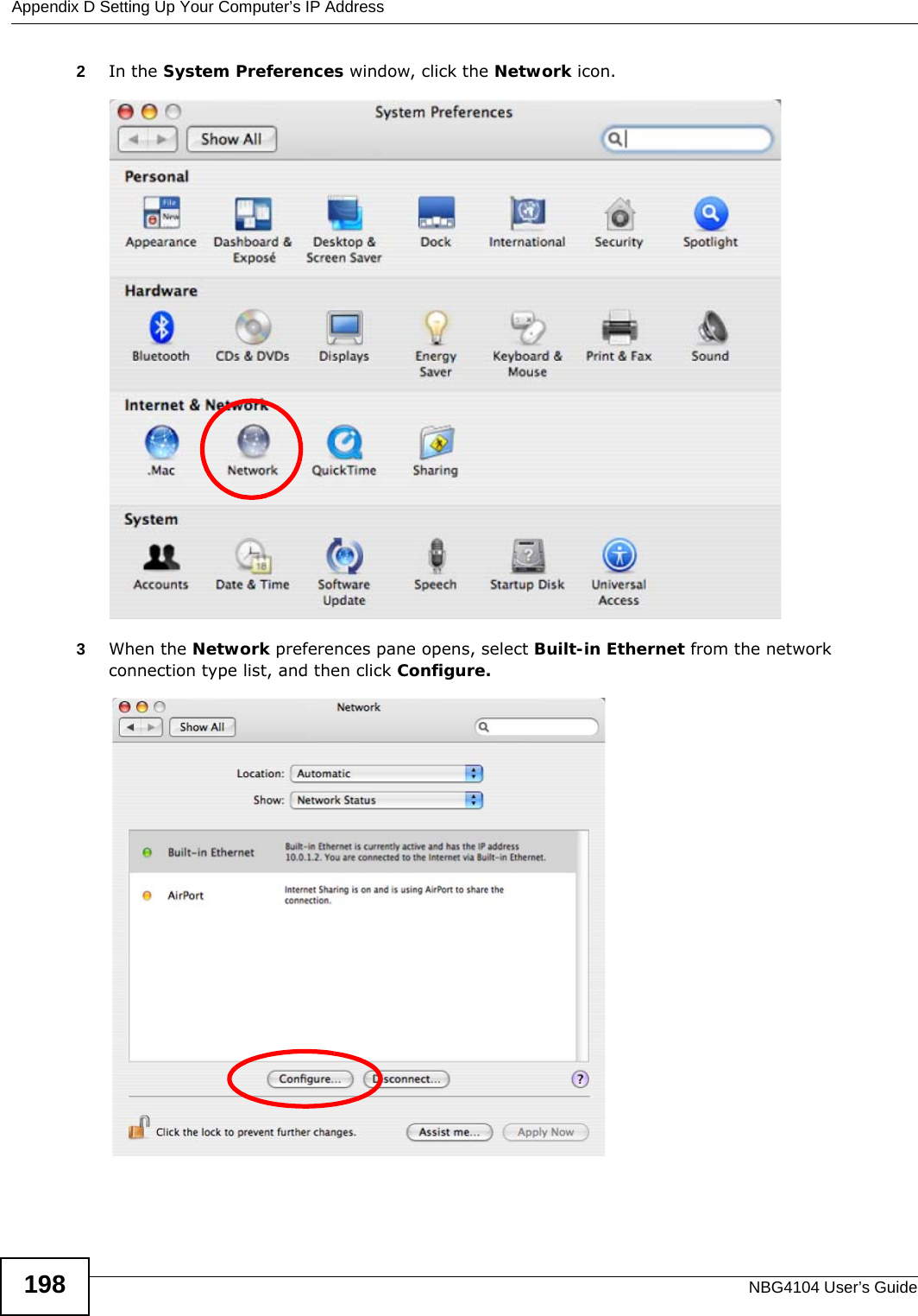
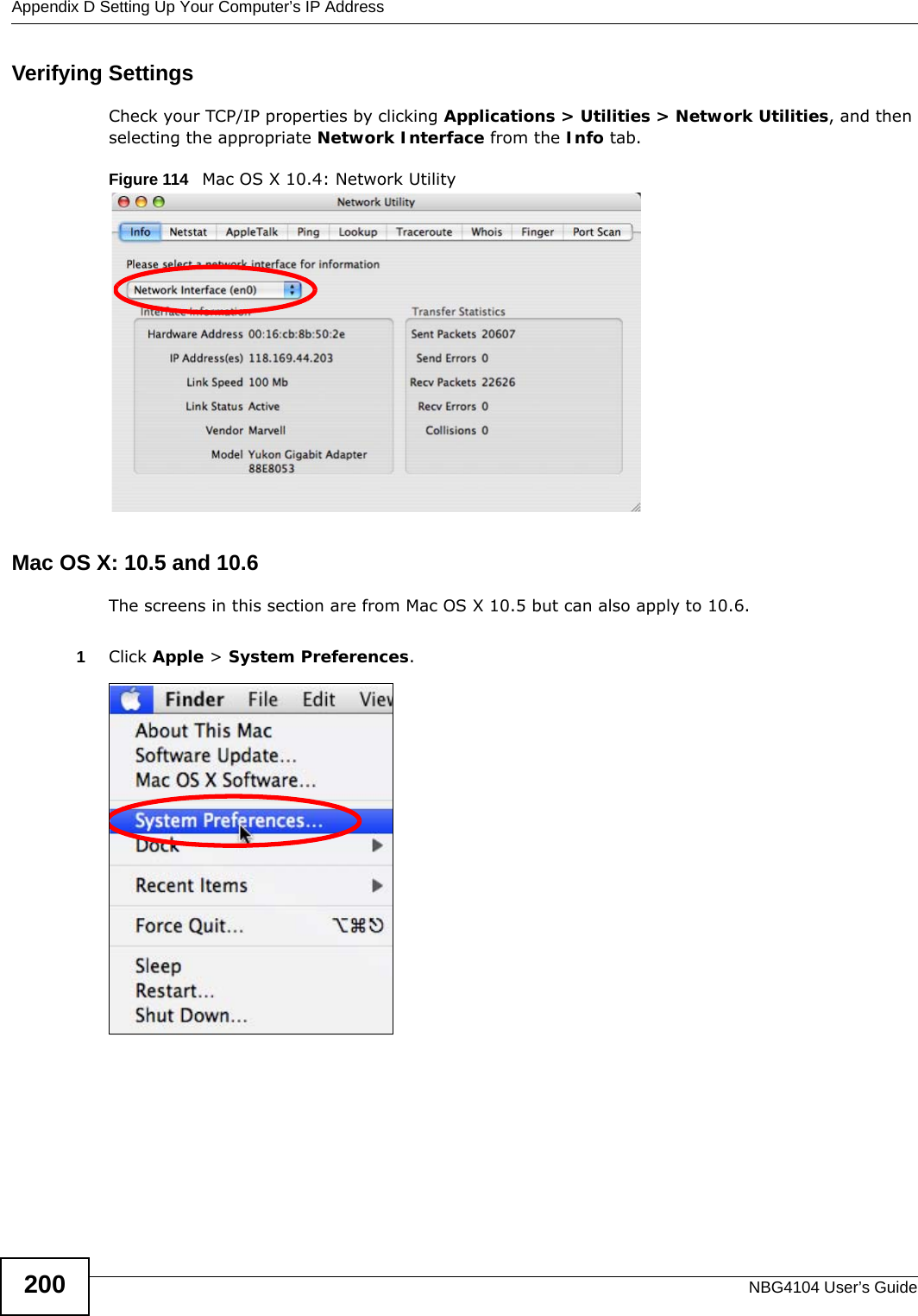
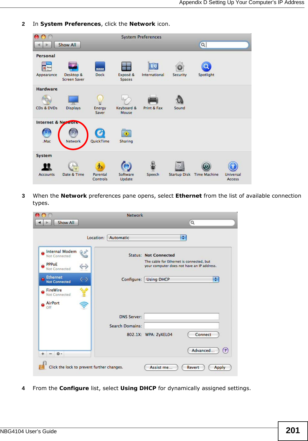
![Appendix D Setting Up Your Computer’s IP AddressNBG4104 User’s Guide 197Verifying Settings1Click Start > All Programs > Accessories > Command Prompt.2In the Command Prompt window, type "ipconfig" and then press [ENTER]. 3The IP settings are displayed as follows.Mac OS X: 10.3 and 10.4The screens in this section are from Mac OS X 10.4 but can also apply to 10.3.1Click Apple > System Preferences.](https://usermanual.wiki/ZyXEL-Communications/NBG4104/User-Guide-1621838-Page-197.png)

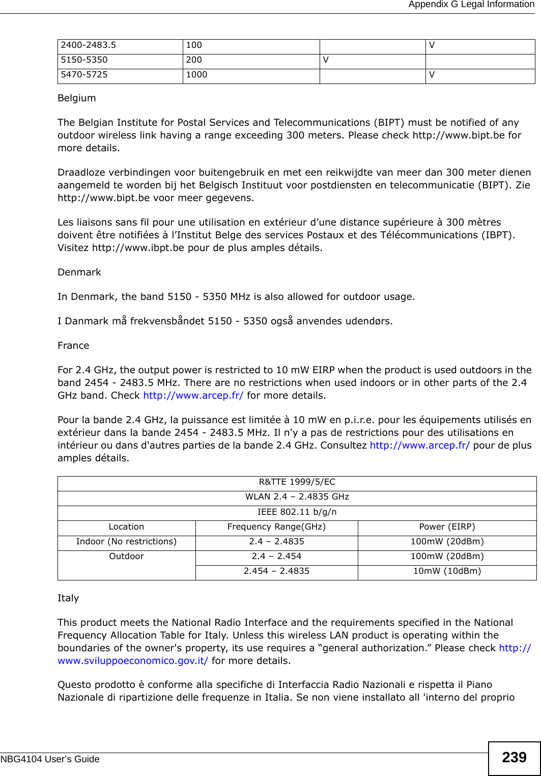
![Appendix G Legal InformationNBG4104 User’s Guide 237Note: Some components of this product incorporate source code covered under the Apache License, GPL License, LGPL License, Sun License, and Castor License. To obtain the source code covered under those Licenses, please check ://opensource.zyxel.com to get it.Regulatory InformationEuropean UnionThe following information applies if you use the product within the European Union. Declaration of Conformity with Regard to EU Directive 1999/5/EC (R&TTE Directive)Compliance Information for 2.4GHz and 5GHz Wireless Products Relevant to the EU and Other Countries Following the EU Directive 1999/5/EC (R&TTE Directive) [Czech] ZyXEL tímto prohlašuje, že tento zařízení je ve shodě se základními požadavky a dalšími příslušnými ustanoveními směrnice 1999/5/EC.[Danish] Undertegnede ZyXEL erklærer herved, at følgende udstyr udstyr overholder de væsentlige krav og øvrige relevante krav i direktiv 1999/5/EF.[German] Hiermit erklärt ZyXEL, dass sich das Gerät Ausstattung in Übereinstimmung mit den grundlegenden Anforderungen und den übrigen einschlägigen Bestimmungen der Richtlinie 1999/5/EU befindet.[Estonian] Käesolevaga kinnitab ZyXEL seadme seadmed vastavust direktiivi 1999/5/EÜ põhinõuetele ja nimetatud direktiivist tulenevatele teistele asjakohastele sätetele.English Hereby, ZyXEL declares that this equipment is in compliance with the essential requirements and other relevant provisions of Directive 1999/5/EC.[Spanish] Por medio de la presente ZyXEL declara que el equipo cumple con los requisitos esenciales y cualesquiera otras disposiciones aplicables o exigibles de la Directiva 1999/5/CE.[Greek] ΜΕ ΤΗΝ ΠΑΡΟΥΣΑ ZyXEL ΔΗΛΩΝΕΙ ΟΤΙ εξοπλισμός ΣΥΜΜΟΡΦΩΝΕΤΑΙ ΠΡΟΣ ΤΙΣ ΟΥΣΙΩΔΕΙΣ ΑΠΑΙΤΗΣΕΙΣ ΚΑΙ ΤΙΣ ΛΟΙΠΕΣ ΣΧΕΤΙΚΕΣ ΔΙΑΤΑΞΕΙΣ ΤΗΣ ΟΔΗΓΙΑΣ 1999/5/ΕC.[French] Par la présente ZyXEL déclare que l'appareil équipements est conforme aux exigences essentielles et aux autres dispositions pertinentes de la directive 1999/5/EC.[Italian] Con la presente ZyXEL dichiara che questo attrezzatura è conforme ai requisiti essenziali ed alle altre disposizioni pertinenti stabilite dalla direttiva 1999/5/CE.[Latvian] Ar šo ZyXEL deklarē, ka iekārtas atbilst Direktīvas 1999/5/EK būtiskajām prasībām un citiem ar to saistītajiem noteikumiem.[Lithuanian] Šiuo ZyXEL deklaruoja, kad šis įranga atitinka esminius reikalavimus ir kitas 1999/5/EB Direktyvos nuostatas.[Dutch] Hierbij verklaart ZyXEL dat het toestel uitrusting in overeenstemming is met de essentiële eisen en de andere relevante bepalingen van richtlijn 1999/5/EC.[Maltese] Hawnhekk, ZyXEL, jiddikjara li dan tagħmir jikkonforma mal-ħtiġijiet essenzjali u ma provvedimenti oħrajn relevanti li hemm fid-Dirrettiva 1999/5/EC.[Hungarian] Alulírott, ZyXEL nyilatkozom, hogy a berendezés megfelel a vonatkozó alapvetõ követelményeknek és az 1999/5/EK irányelv egyéb elõírásainak.[Polish] Niniejszym ZyXEL oświadcza, że sprzęt jest zgodny z zasadniczymi wymogami oraz pozostałymi stosownymi postanowieniami Dyrektywy 1999/5/EC.[Portuguese] ZyXEL declara que este equipamento está conforme com os requisitos essenciais e outras disposições da Directiva 1999/5/EC.](https://usermanual.wiki/ZyXEL-Communications/NBG4104/User-Guide-1621838-Page-237.png)
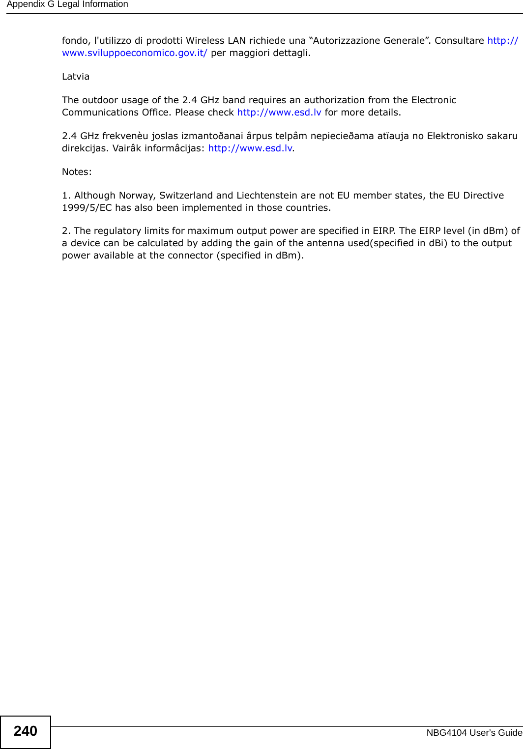
![Appendix G Legal InformationNBG4104 User’s Guide238National RestrictionsThis product may be used in all EU countries (and other countries following the EU directive 1999/5/EC) without any limitation except for the countries mentioned below:Ce produit peut être utilisé dans tous les pays de l’UE (et dans tous les pays ayant transposés la directive 1999/5/CE) sans aucune limitation, excepté pour les pays mentionnés ci-dessous:Questo prodotto è utilizzabile in tutte i paesi EU (ed in tutti gli altri paesi che seguono le direttive EU 1999/5/EC) senza nessuna limitazione, eccetto per i paesii menzionati di seguito:Das Produkt kann in allen EU Staaten ohne Einschränkungen eingesetzt werden (sowie in anderen Staaten die der EU Direktive 1995/5/CE folgen) mit Außnahme der folgenden aufgeführten Staaten:In the majority of the EU and other European countries, the 2, 4- and 5-GHz bands have been made available for the use of wireless local area networks (LANs). Later in this document you will find an overview of countries inwhich additional restrictions or requirements or both are applicable.The requirements for any country may evolve. ZyXEL recommends that you check with the local authorities for the latest status of their national regulations for both the 2,4- and 5-GHz wireless LANs.The following countries have restrictions and/or requirements in addition to those given in the table labeled “Overview of Regulatory Requirements for Wireless LANs”:.[Slovenian] ZyXEL izjavlja, da je ta oprema v skladu z bistvenimi zahtevami in ostalimi relevantnimi določili direktive 1999/5/EC.[Slovak] ZyXEL týmto vyhlasuje, že zariadenia spĺňa základné požiadavky a všetky príslušné ustanovenia Smernice 1999/5/EC.[Finnish] ZyXEL vakuuttaa täten että laitteet tyyppinen laite on direktiivin 1999/5/EY oleellisten vaatimusten ja sitä koskevien direktiivin muiden ehtojen mukainen.[Swedish] Härmed intygar ZyXEL att denna utrustning står I överensstämmelse med de väsentliga egenskapskrav och övriga relevanta bestämmelser som framgår av direktiv 1999/5/EC.[Bulgarian] С настоящото ZyXEL декларира, че това оборудване е в съответствие със съществените изисквания и другите приложими разпоредбите на Директива 1999/5/ЕC.[Icelandic] Hér með lýsir, ZyXEL því yfir að þessi búnaður er í samræmi við grunnkröfur og önnur viðeigandi ákvæði tilskipunar 1999/5/EC.[Norwegian] Erklærer herved ZyXEL at dette utstyret er I samsvar med de grunnleggende kravene og andre relevante bestemmelser I direktiv 1999/5/EF.[Romanian] Prin prezenta, ZyXEL declară că acest echipament este în conformitate cu cerinţele esenţiale şi alte prevederi relevante ale Directivei 1999/5/EC.Overview of Regulatory Requirements for Wireless LANs Frequency Band (MHz) Max Power Level (EIRP)1 (mW) Indoor ONLY Indoor and Outdoor](https://usermanual.wiki/ZyXEL-Communications/NBG4104/User-Guide-1621838-Page-238.png)