ZyXEL Communications NBG410W3G 3G Wireless Router User Manual NBG41xW3G UG V4 03 Ed1 2008 08 15 DRAFT
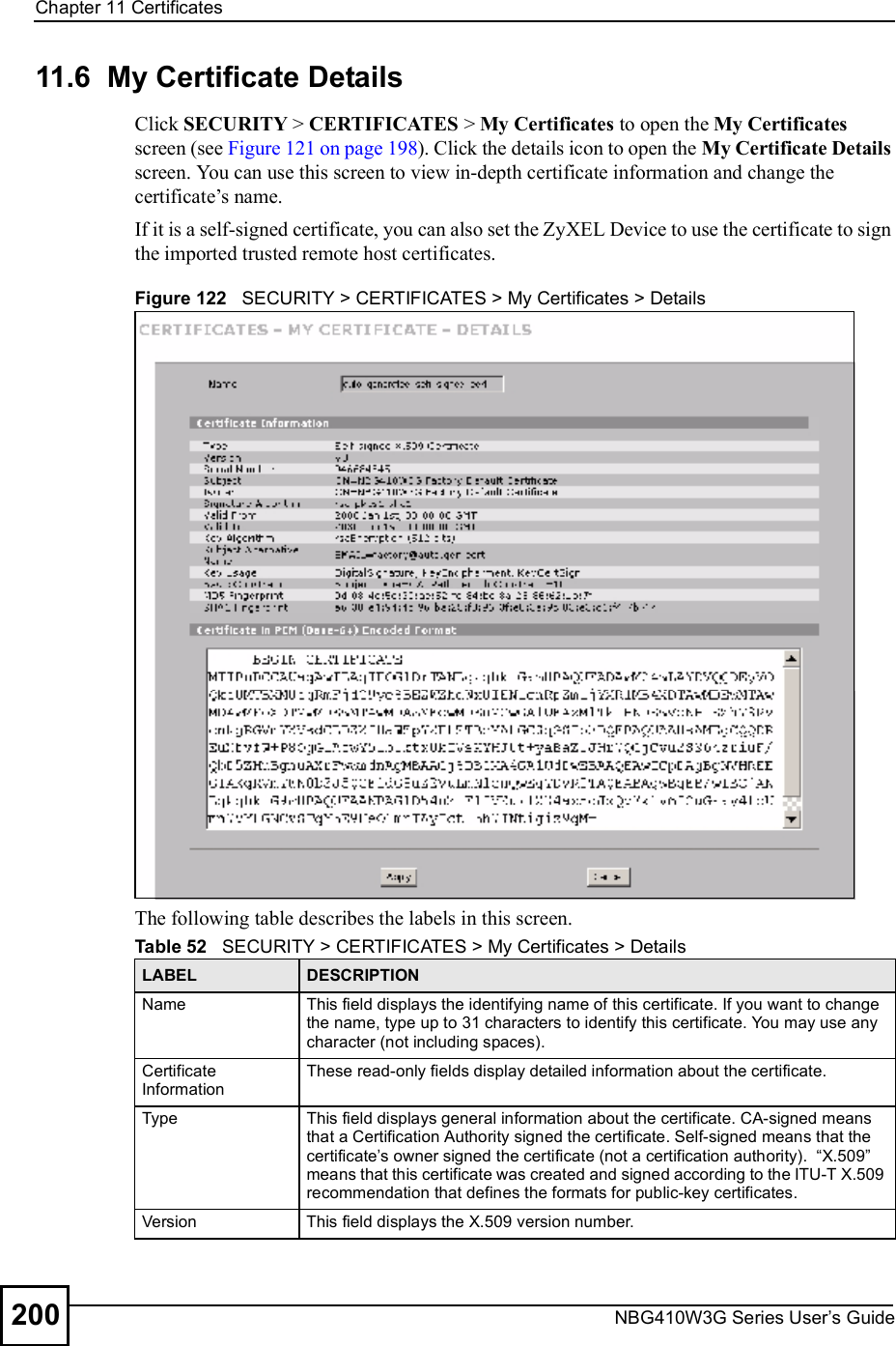
ZyXEL Communications Corporation 3G Wireless Router NBG41xW3G UG V4 03 Ed1 2008 08 15 DRAFT
Contents
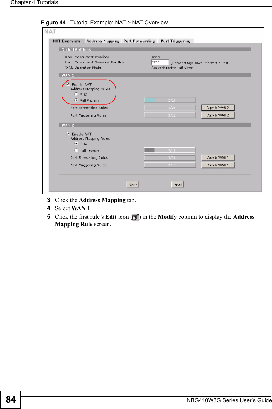
- 1. User manual 1 rev2
- 2. User manual 2 rev2
User manual 1 rev2
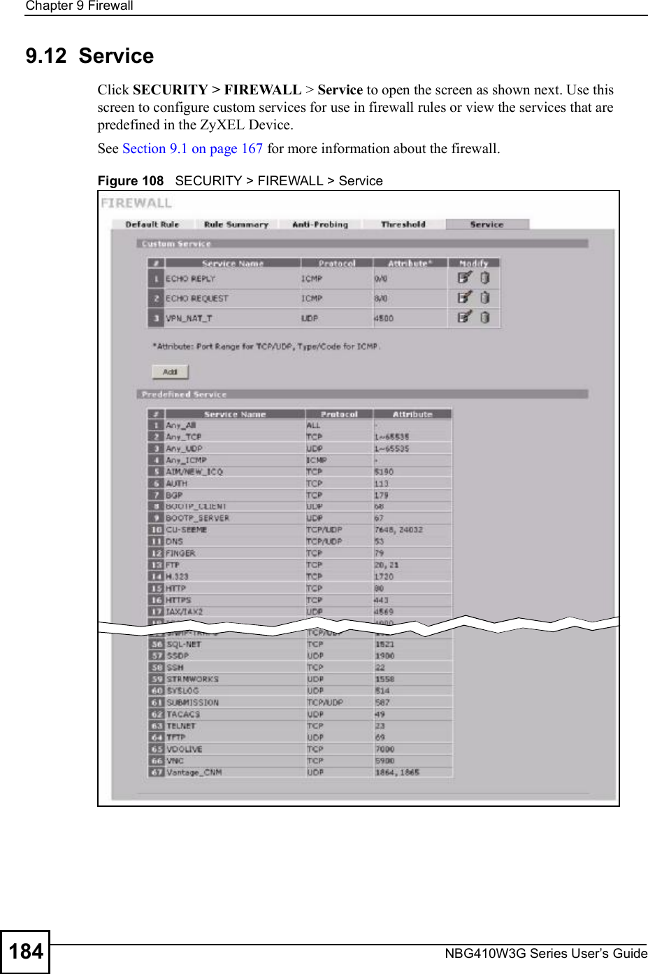
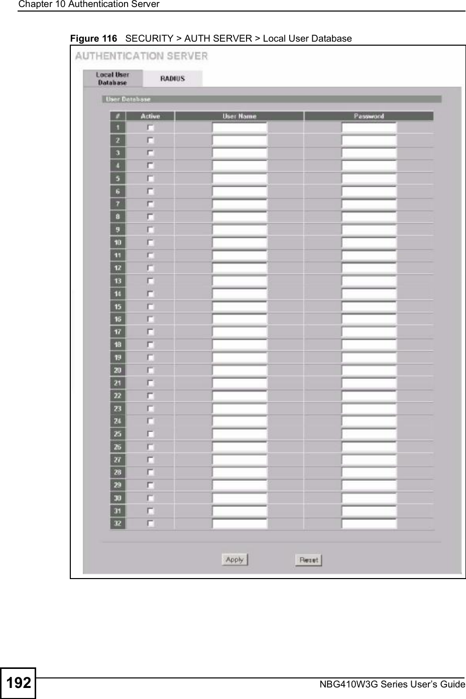
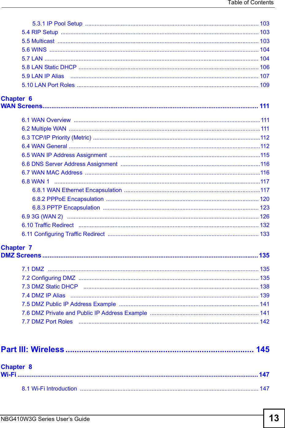
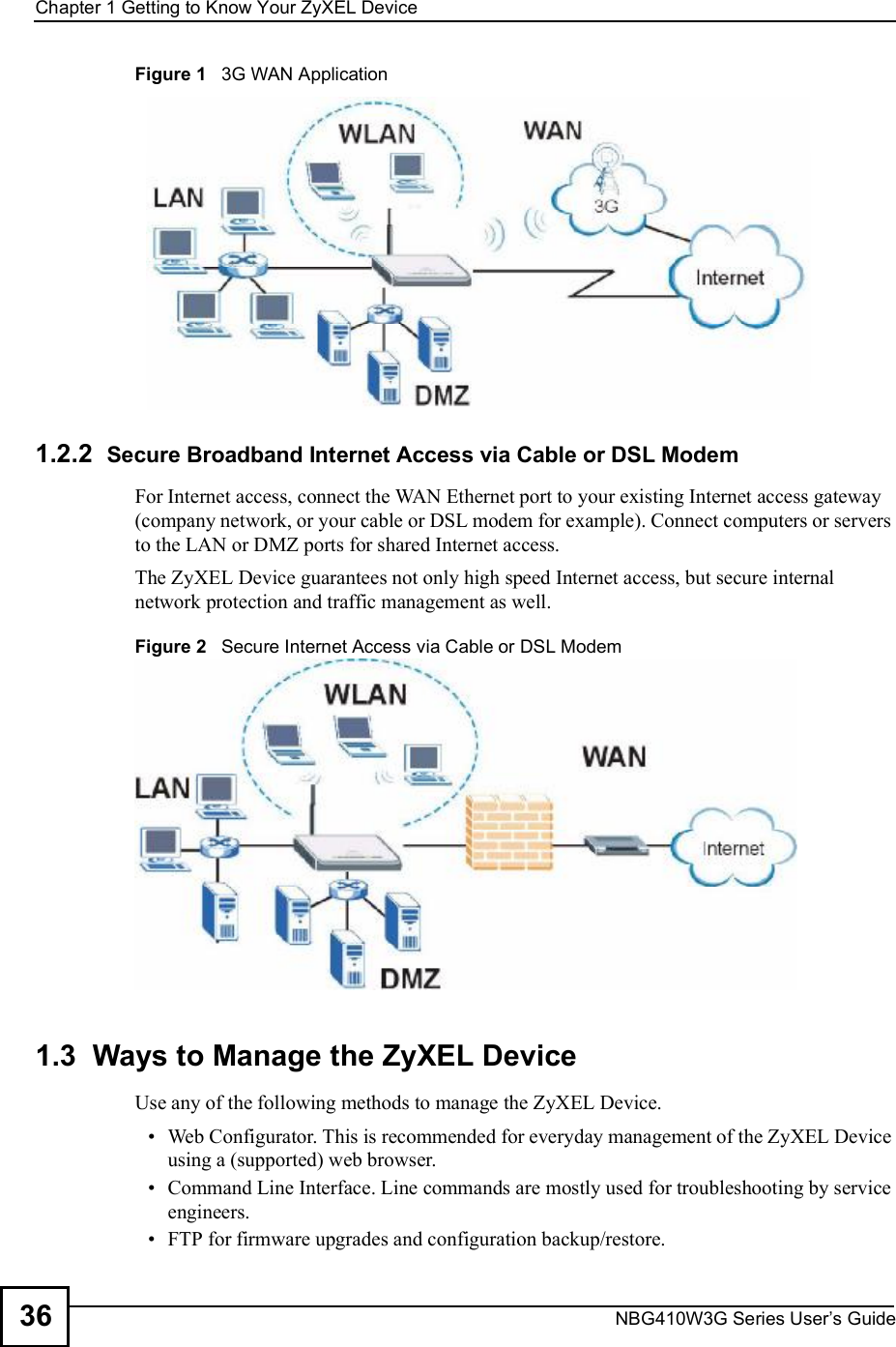
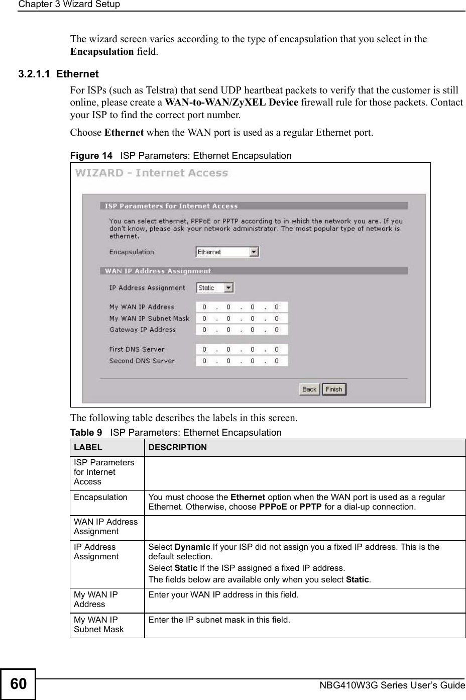
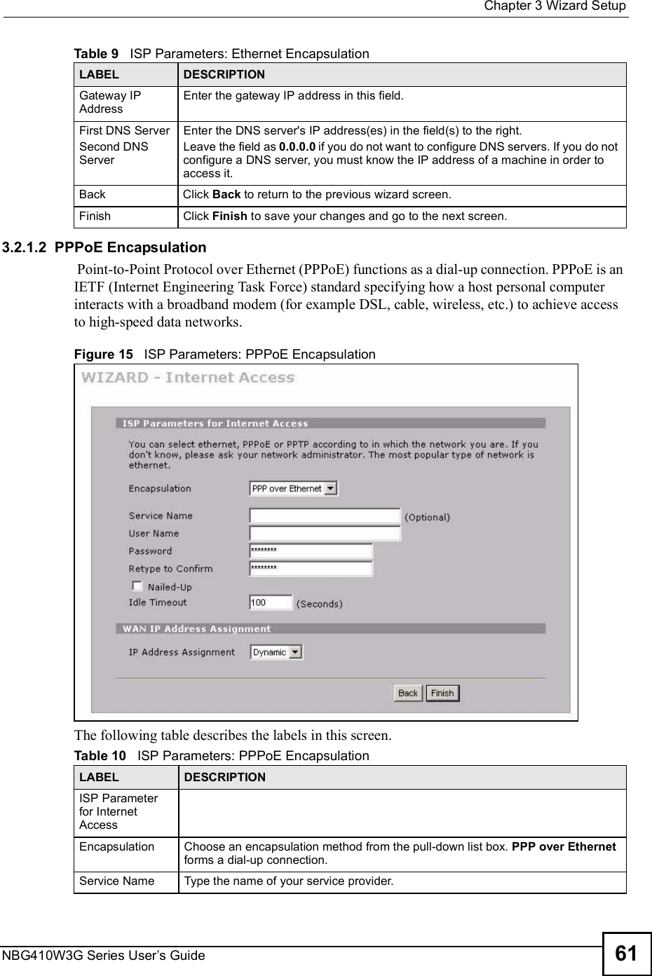
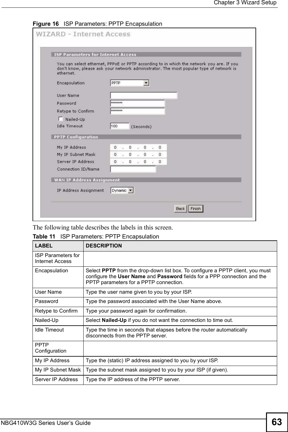
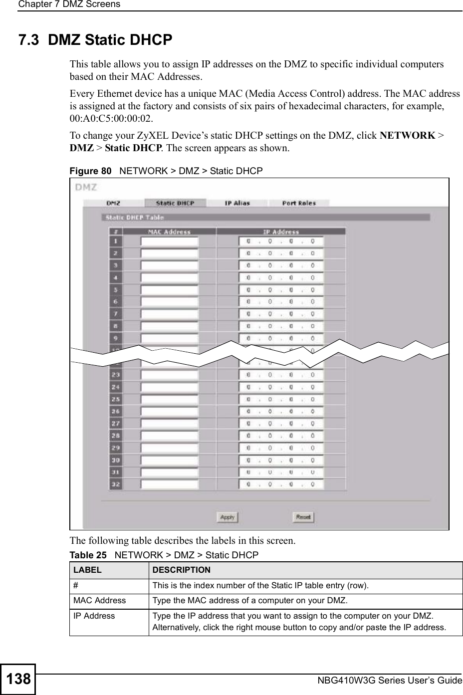
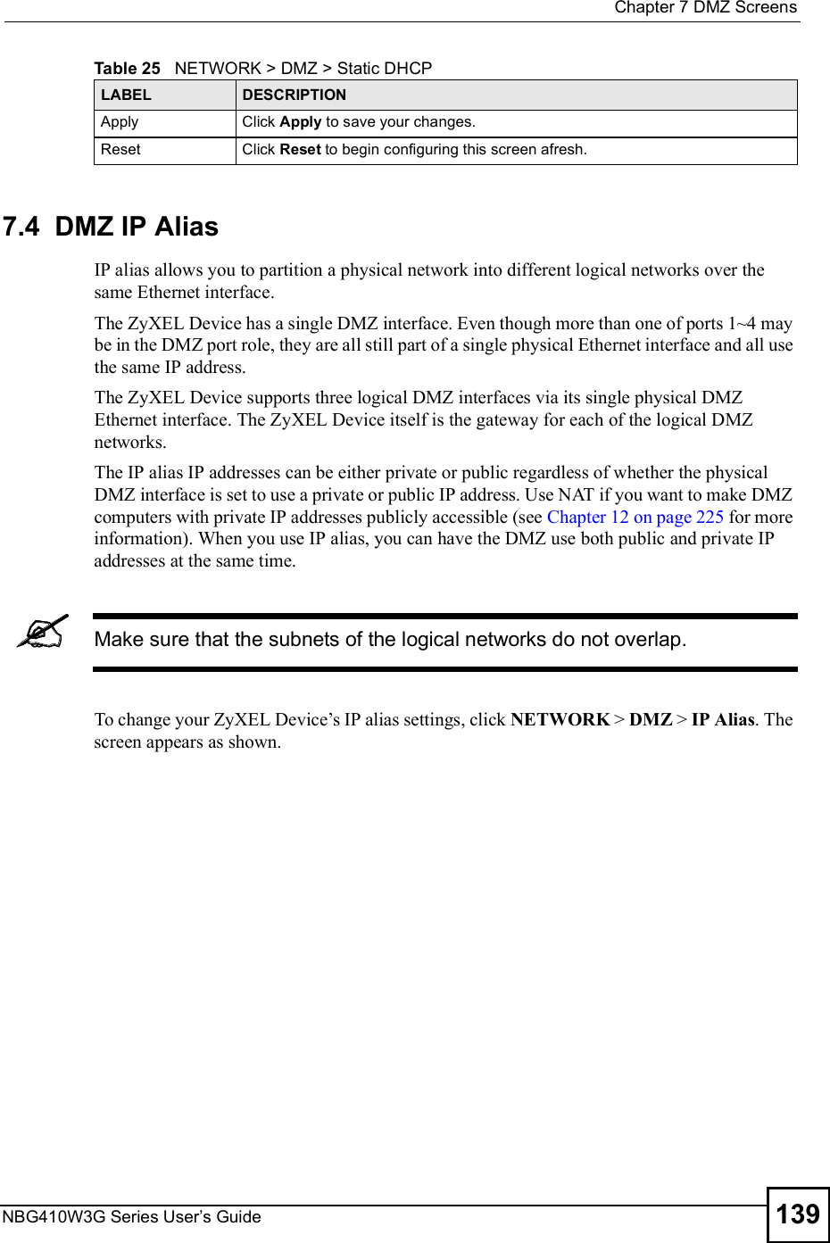
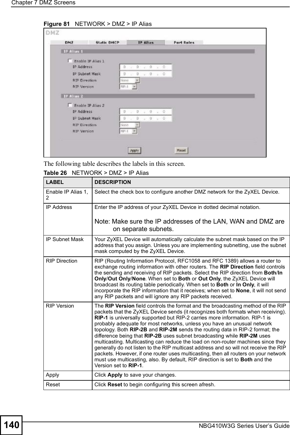
![Document ConventionsNBG410W3G Series User s Guide4Document ConventionsWarnings and NotesThese are how warnings and notes are shown in this User!s Guide. Warnings tell you about things that could harm you or your device.Notes tell you other important information (for example, other things you may need to configure or helpful tips) or recommendations.Syntax Conventions The NBG410W3G and NBG412W3G may be referred to as the "ZyXEL Device#, the "device#, the "system#, or the "NBG410W3G Series# in this User!s Guide. Product labels, screen names, field labels and field choices are all in bold font. A key stroke is denoted by square brackets and uppercase text, for example, [ENTER] means the "enter# or "return# key on your keyboard. "Enter# means for you to type one or more characters and then press the [ENTER] key. "Select# or "choose# means for you to use one of the predefined choices. A right angle bracket ( > ) within a screen name denotes a mouse click. For example, Maintenance > Log > Log Setting means you first click Maintenance in the navigation panel, then the Log sub menu and finally the Log Setting tab to get to that screen. Units of measurement may denote the "metric# value or the "scientific# value. For example, "k# for kilo may denote "1000# or "1024#, "M# for mega may denote "1000000# or "1048576# and so on. "e.g.,# is a shorthand for "for instance#, and "i.e.,# means "that is# or "in other words#.](https://usermanual.wiki/ZyXEL-Communications/NBG410W3G.User-manual-1-rev2/User-Guide-986479-Page-4.png)

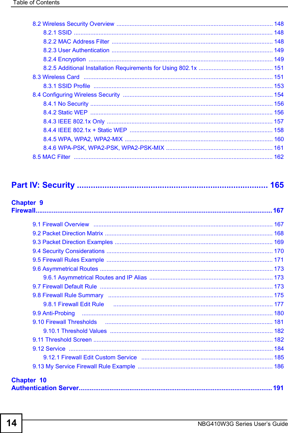

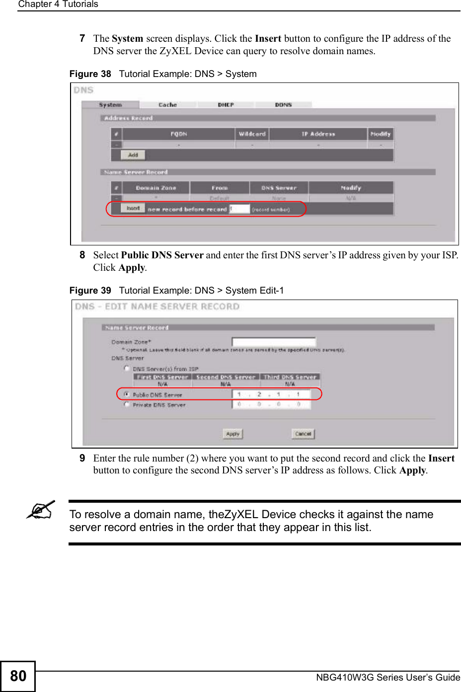
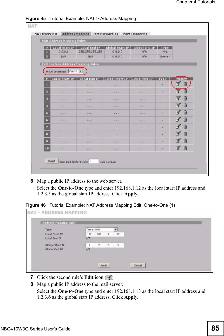


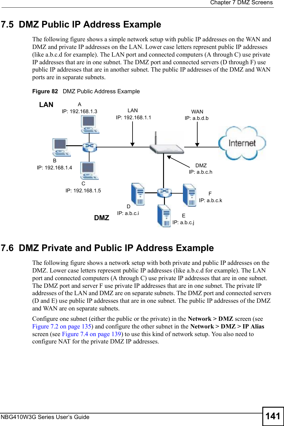


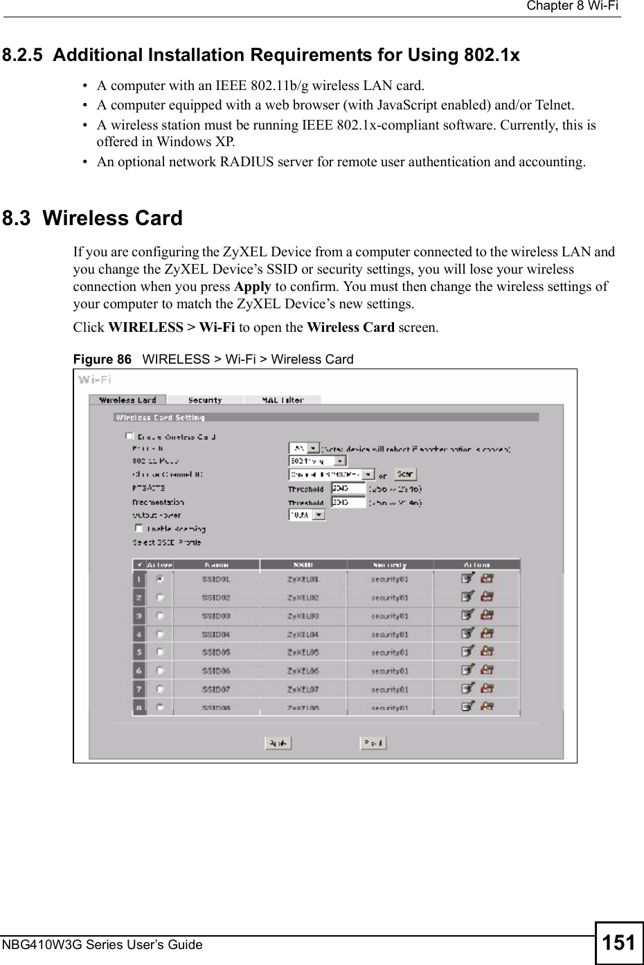


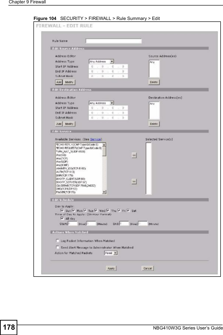
![Chapter 9FirewallNBG410W3G Series User s Guide 179The following table describes the labels in this screen. Table 44 SECURITY > FIREWALL > Rule Summary > EditLABEL DESCRIPTIONRule NameEnter a descriptive name of up to 31 printable ASCII characters (except Extended ASCII characters) for the firewall rule. Spaces are allowed. Edit Source/Destination AddressAddress TypeDo you want your rule to apply to packets with a particular (single) IP, a range of IP addresses (for example 192.168.1.10 to 192.169.1.50), a subnet or any IP address? Select an option from the drop-down list box that includes: Single Address, Range Address, Subnet Address and Any Address.Start IP AddressEnter the single IP address or the starting IP address in a range here. End IP AddressEnter the ending IP address in a range here.Subnet MaskEnter the subnet mask here, if applicable.AddClick Add to add a new address to the Source or Destination Address(es) box. You can add multiple addresses, ranges of addresses, and/or subnets.ModifyTo edit an existing source or destination address, select it from the box and click Modify.DeleteHighlight an existing source or destination address from the Source or Destination Address(es) box above and click Delete to remove it.Edit ServiceAvailable/ Selected ServicesHighlight a service from the Available Services box on the left, then click >> to add it to the Selected Service(s) box on the right. To remove a service, highlight it in the Selected Service(s) box on the right, then click <<.Next to the name of a service, two fields appear in brackets. The first field indicates the IP protocol type (TCP, UDP, or ICMP). The second field indicates the IP port number that defines the service. (Note that there may be more than one IP protocol type). For example, look at the DNS entry, (UDP/TCP:53) means UDP port 53 and TCP port 53. Click the Service link to go to the Service screen where you can configure custom service ports. See Appendix D on page 385 for a list of commonly used services and port numbers. You can use the [CTRL] key and select multiple services at once.Edit ScheduleDay to ApplySelect everyday or the day(s) of the week to apply the rule.Time of Day to Apply (24-Hour Format)Select All Day or enter the start and end times in the hour-minute format to apply the rule.Actions When MatchedLog Packet Information When MatchedThis field determines if a log for packets that match the rule is created (Yes) or not (No). Go to the Log Settings page and select the Access Control logs category to have the ZyXEL Device record these logs.Send Alert Message to Administrator When MatchedSelect the check box to have the ZyXEL Device generate an alert when the rule is matched.](https://usermanual.wiki/ZyXEL-Communications/NBG410W3G.User-manual-1-rev2/User-Guide-986479-Page-179.png)