ZyXEL Communications NBG410W3G 3G Wireless Router User Manual NBG41xW3G UG V4 03 Ed1 2008 08 15 DRAFT
ZyXEL Communications Corporation 3G Wireless Router NBG41xW3G UG V4 03 Ed1 2008 08 15 DRAFT
Contents
- 1. User manual 1 rev2
- 2. User manual 2 rev2
User manual 2 rev2


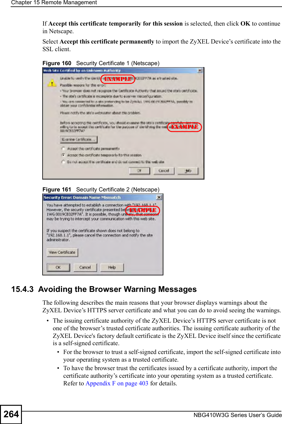
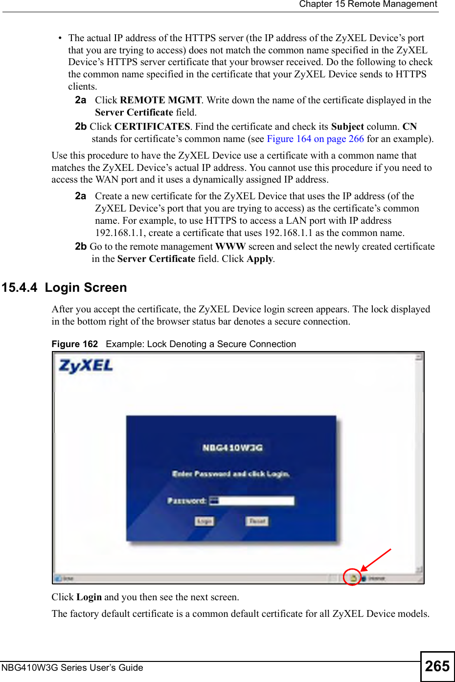
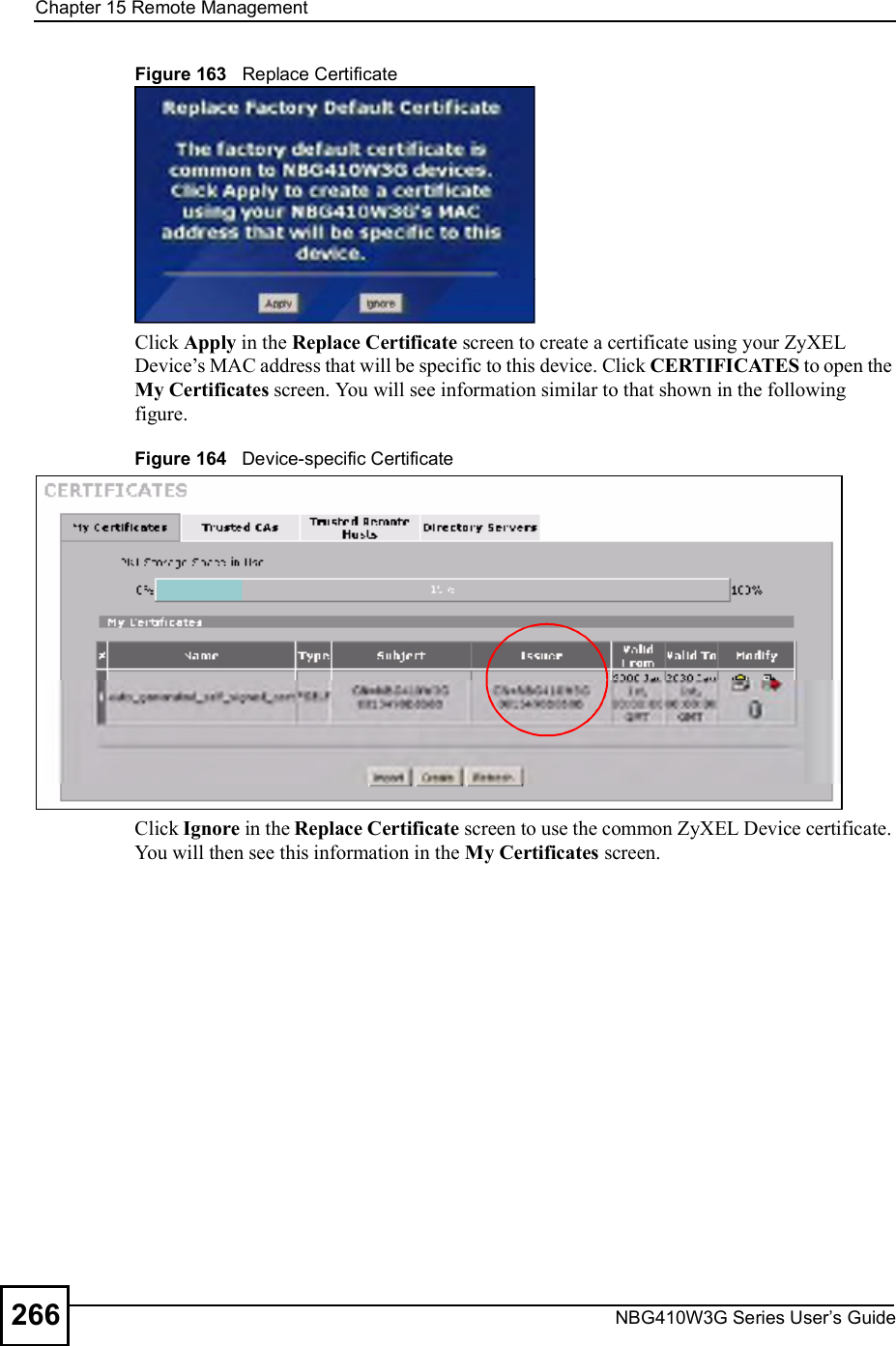
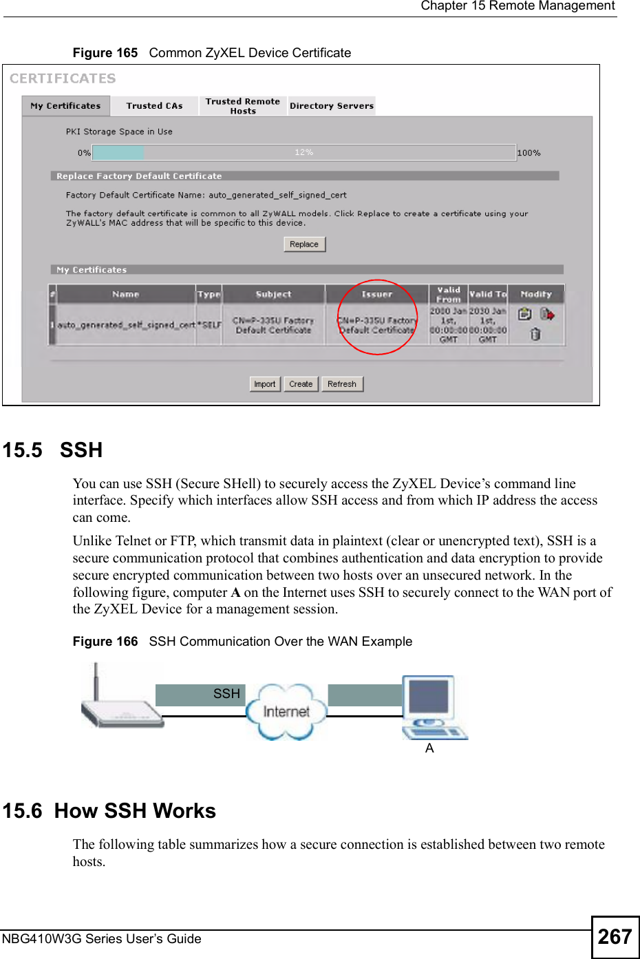
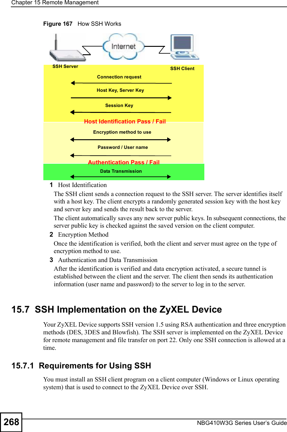
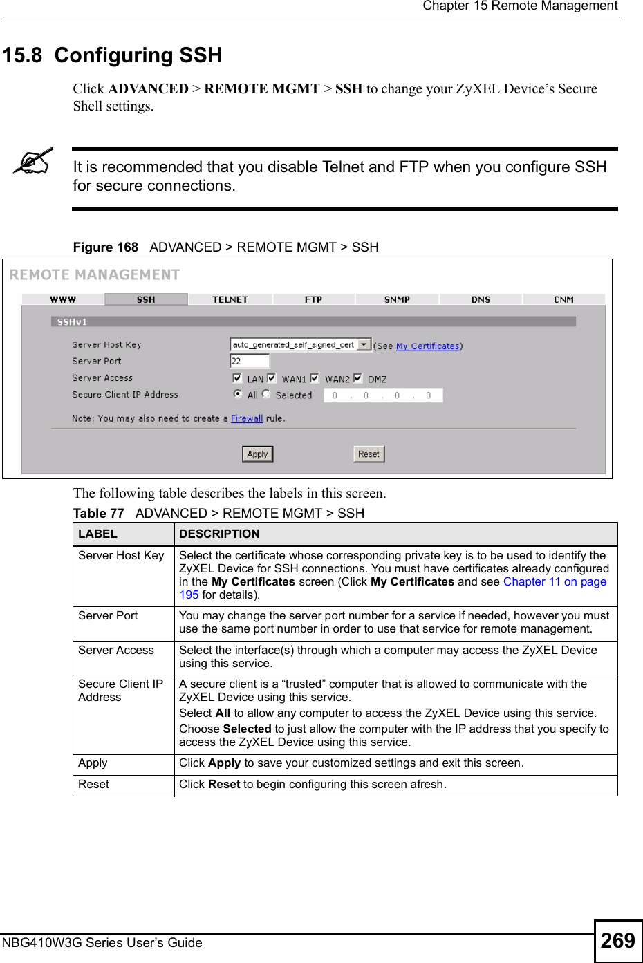
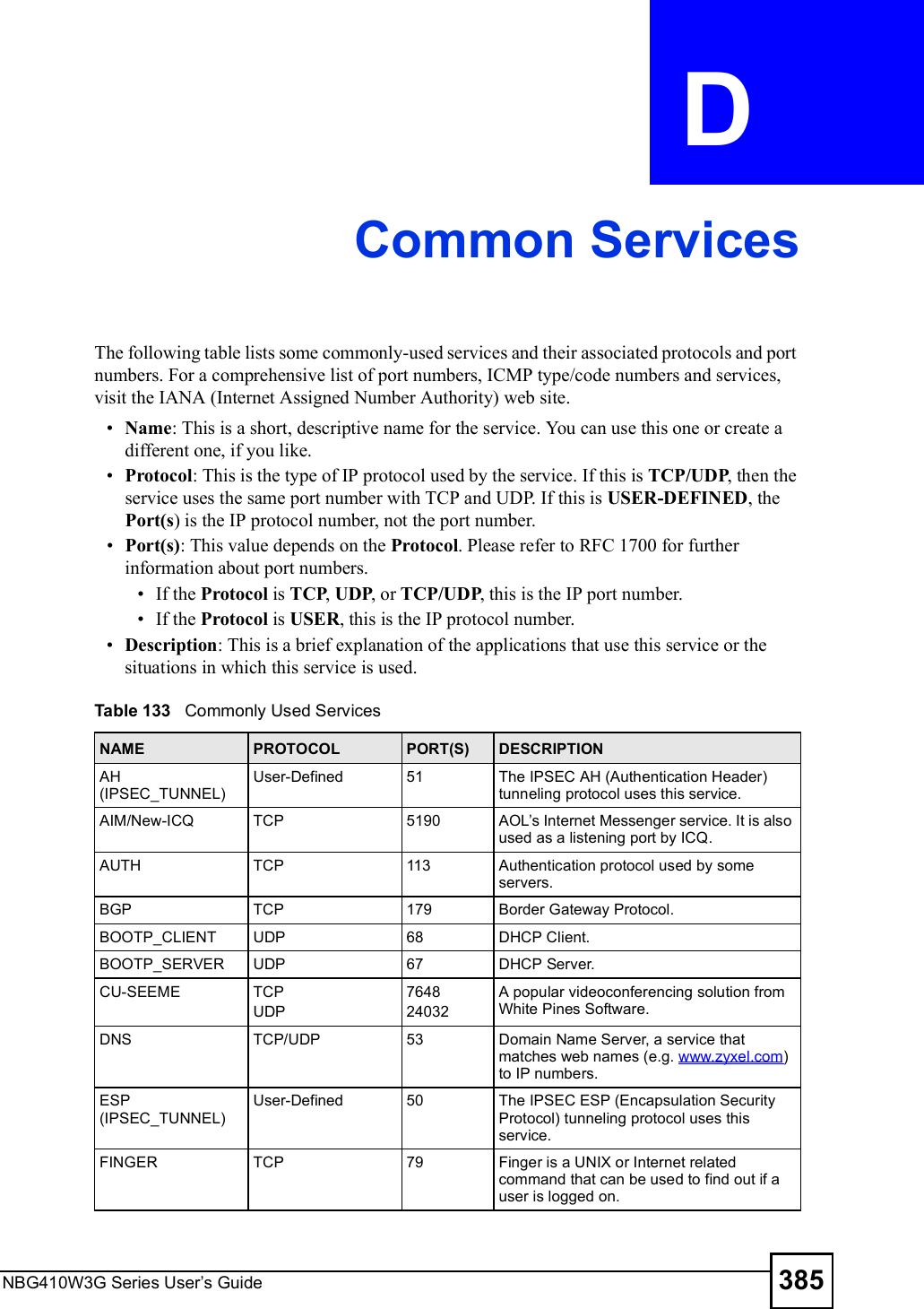
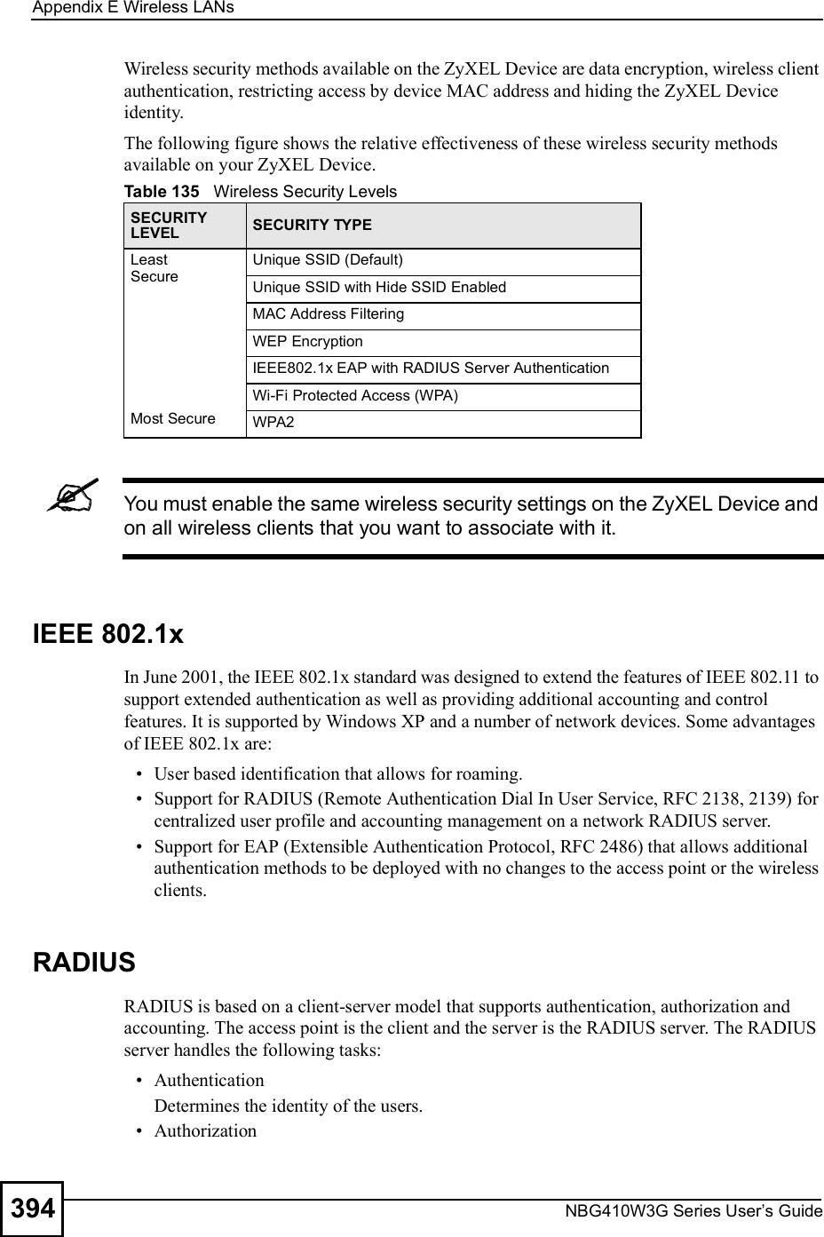
![Chapter 15Remote ManagementNBG410W3G Series User s Guide27015.9 Secure Telnet Using SSH ExamplesThis section shows two examples using a command interface and a graphical interface SSH client program to remotely access the ZyXEL Device. The configuration and connection steps are similar for most SSH client programs. Refer to your SSH client program user!s guide. 15.9.1 Example 1: Microsoft Windows This section describes how to access the ZyXEL Device using the Secure Shell Client program.1Launch the SSH client and specify the connection information (IP address, port number or device name) for the ZyXEL Device. 2Configure the SSH client to accept connection using SSH version 1. 3A window displays prompting you to store the host key in you computer. Click Yes to continue. Figure 169 SSH Example 1: Store Host KeyEnter the password to log in to the ZyXEL Device. The CLI main menu displays next. 15.9.2 Example 2: LinuxThis section describes how to access the ZyXEL Device using the OpenSSH client program that comes with most Linux distributions. 1Test whether the SSH service is available on the ZyXEL Device. Enter "telnet 192.168.1.1 22# at a terminal prompt and press [ENTER]. The computer attempts to connect to port 22 on the ZyXEL Device (using the default IP address of 192.168.1.1). A message displays indicating the SSH protocol version supported by the ZyXEL Device. Figure 170 SSH Example 2: Test $ telnet 192.168.1.1 22Trying 192.168.1.1...Connected to 192.168.1.1.Escape character is '^]'.SSH-1.5-1.0.0](https://usermanual.wiki/ZyXEL-Communications/NBG410W3G.User-manual-2-rev2/User-Guide-986480-Page-70.png)
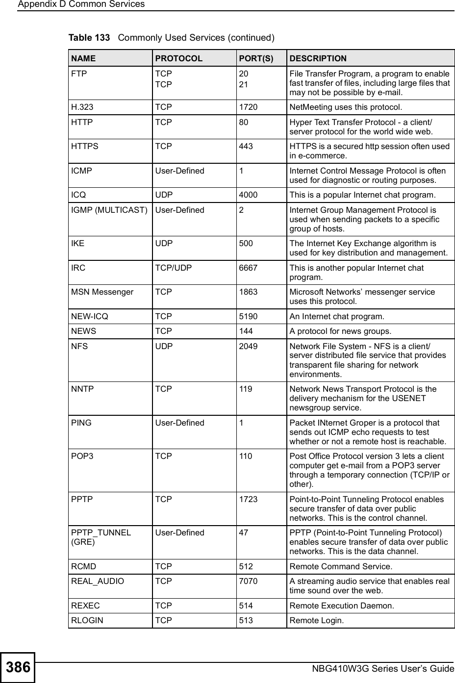
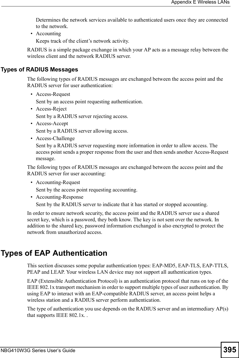
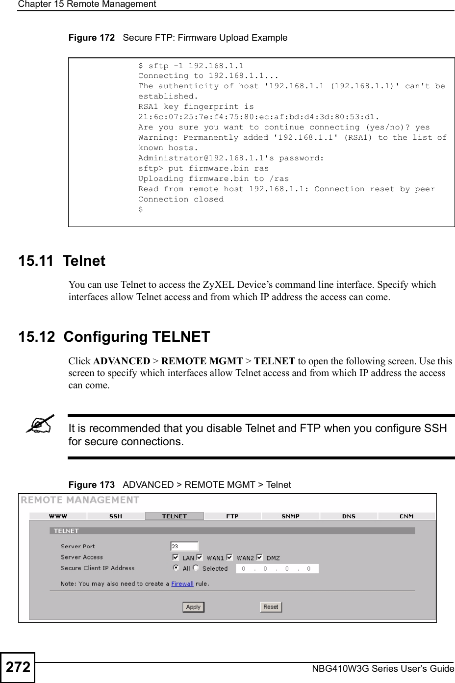
![Chapter 15Remote ManagementNBG410W3G Series User s Guide 2712Enter "ssh 1 192.168.1.1#. This command forces your computer to connect to the ZyXEL Device using SSH version 1. If this is the first time you are connecting to the ZyXEL Device using SSH, a message displays prompting you to save the host information of the ZyXEL Device. Type "yes# and press [ENTER]. Then enter the password to log in to the ZyXEL Device. Figure 171 SSH Example 2: Log in3The CLI main menu displays next. 15.10 Secure FTP Using SSH ExampleThis section shows an example on file transfer using the OpenSSH client program. The configuration and connection steps are similar for other SSH client programs. Refer to your SSH client program user!s guide.1Enter "sftp 1 192.168.1.1#. This command forces your computer to connect to the ZyXEL Device for secure file transfer using SSH version 1. If this is the first time you are connecting to the ZyXEL Device using SSH, a message displays prompting you to save the host information of the ZyXEL Device. Type "yes# and press [ENTER].2Enter the password to login to the ZyXEL Device. 3Use the "put# command to upload a new firmware to the ZyXEL Device. $ ssh 1 192.168.1.1The authenticity of host '192.168.1.1 (192.168.1.1)' can't be established.RSA1 key fingerprint is 21:6c:07:25:7e:f4:75:80:ec:af:bd:d4:3d:80:53:d1.Are you sure you want to continue connecting (yes/no)? yesWarning: Permanently added '192.168.1.1' (RSA1) to the list of known hosts.Administrator@192.168.1.1's password:](https://usermanual.wiki/ZyXEL-Communications/NBG410W3G.User-manual-2-rev2/User-Guide-986480-Page-71.png)


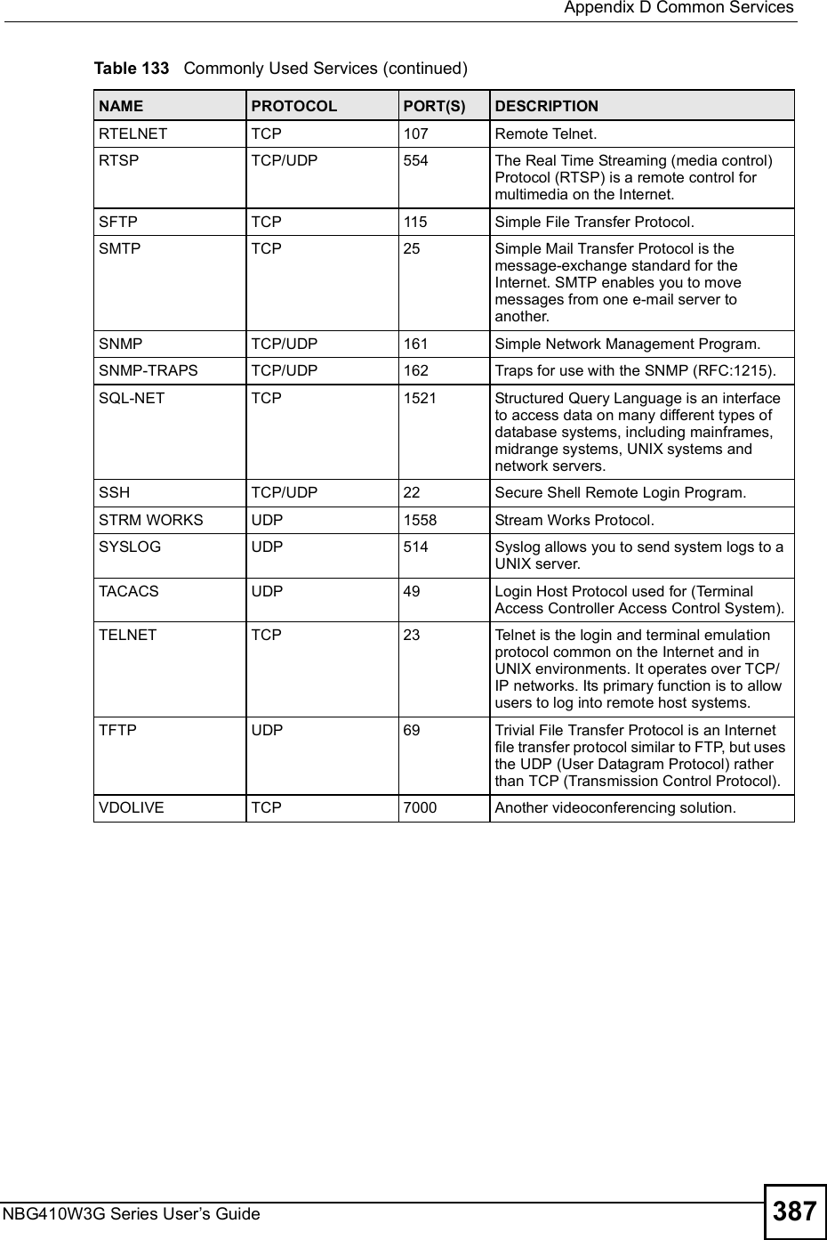
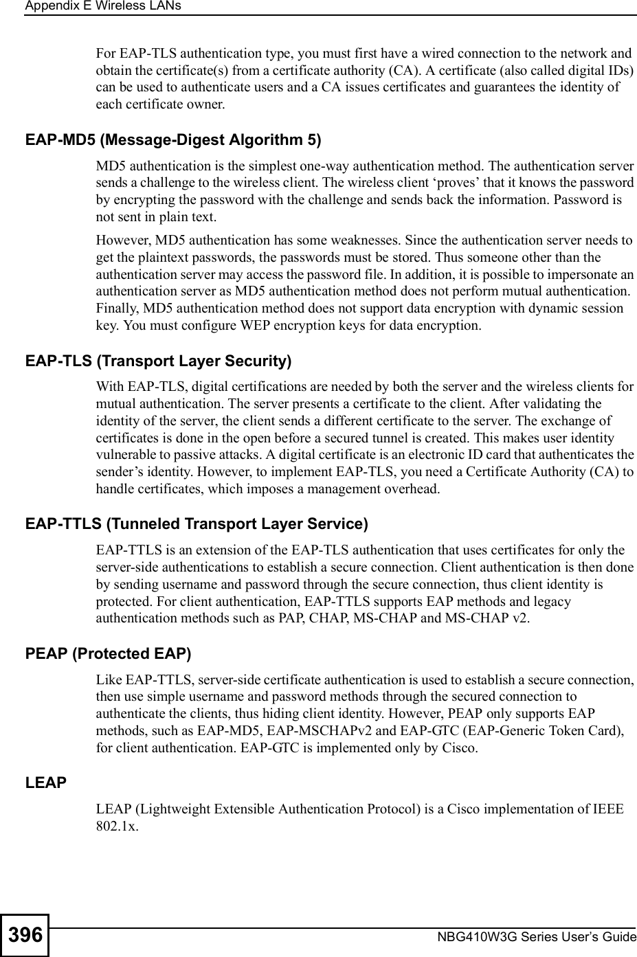
![Chapter 19Logs ScreensNBG410W3G Series User s Guide314 Table 98 Access Control LogsLOG MESSAGE DESCRIPTIONFirewall default policy: [ TCP | UDP | IGMP | ESP | GRE | OSPF ] <Packet Direction>Attempted TCP/UDP/IGMP/ESP/GRE/OSPF access matched the default policy and was blocked or forwarded according to the default policy s setting.Firewall rule [NOT] match:[ TCP | UDP | IGMP | ESP | GRE | OSPF ] <Packet Direction>, <rule:%d>Attempted TCP/UDP/IGMP/ESP/GRE/OSPF access matched (or did not match) a configured firewall rule (denoted by its number) and was blocked or forwarded according to the rule. Triangle route packet forwarded: [ TCP | UDP | IGMP | ESP | GRE | OSPF ]The firewall allowed a triangle route session to pass through.Packet without a NAT table entry blocked: [ TCP | UDP | IGMP | ESP | GRE | OSPF ]The router blocked a packet that didn't have a corresponding NAT table entry.Router sent blocked web site message: TCPThe router sent a message to notify a user that the router blocked access to a web site that the user requested.Exceed maximum sessions per host (%d).The device blocked a session because the host's connections exceeded the maximum sessions per host.Firewall allowed a packet that matched a NAT session: [ TCP | UDP ]A packet from the WAN (TCP or UDP) matched a cone NAT session and the device forwarded it to the LAN.Table 99 TCP Reset LogsLOG MESSAGE DESCRIPTIONUnder SYN flood attack, sent TCP RSTThe router sent a TCP reset packet when a host was under a SYN flood attack (the TCP incomplete count is per destination host.) Exceed TCP MAX incomplete, sent TCP RSTThe router sent a TCP reset packet when the number of TCP incomplete connections exceeded the user configured threshold. (the TCP incomplete count is per destination host.) Note: Refer to TCP Maximum Incomplete in the Firewall Attack Alerts screen. Peer TCP state out of order, sent TCP RSTThe router sent a TCP reset packet when a TCP connection state was out of order.Note: The firewall refers to RFC793 Figure 6 to check the TCP state.Firewall session time out, sent TCP RSTThe router sent a TCP reset packet when a dynamic firewall session timed out.The default timeout values are as follows:ICMP idle timeout: 3 minutesUDP idle timeout: 3 minutesTCP connection (three way handshaking) timeout: 270 secondsTCP FIN-wait timeout: 2 MSL (Maximum Segment Lifetime set in the TCP header).TCP idle (established) timeout (s): 150 minutesTCP reset timeout: 10 seconds](https://usermanual.wiki/ZyXEL-Communications/NBG410W3G.User-manual-2-rev2/User-Guide-986480-Page-114.png)
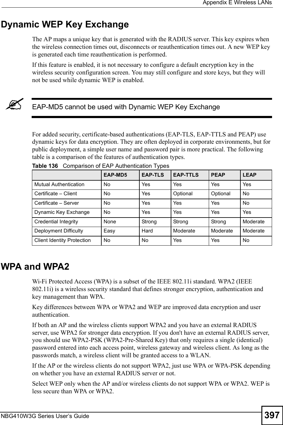
![Chapter 19Logs ScreensNBG410W3G Series User s Guide 315 For type and code details, see Table 110 on page 321.Exceed MAX incomplete, sent TCP RSTThe router sent a TCP reset packet when the number of incomplete connections (TCP and UDP) exceeded the user-configured threshold. (Incomplete count is for all TCP and UDP connections through the firewall.)Note: When the number of incomplete connections (TCP + UDP) > "Maximum Incomplete High#, the router sends TCP RST packets for TCP connections and destroys TOS (firewall dynamic sessions) until incomplete connections < "Maximum Incomplete Low#.Access block, sent TCP RSTThe router sends a TCP RST packet and generates this log if you turn on the firewall TCP reset mechanism (via CI command: "sys firewall tcprst").Table 100 Packet Filter LogsLOG MESSAGE DESCRIPTION[ TCP | UDP | ICMP | IGMP | Generic ] packet filter matched (set: %d, rule: %d)Attempted access matched a configured filter rule (denoted by its set and rule number) and was blocked or forwarded according to the rule.Table 101 ICMP LogsLOG MESSAGE DESCRIPTIONFirewall default policy: ICMP <Packet Direction>, <type:%d>, <code:%d>ICMP access matched the default policy and was blocked or forwarded according to the user's setting.Firewall rule [NOT] match: ICMP <Packet Direction>, <rule:%d>, <type:%d>, <code:%d>ICMP access matched (or didn t match) a firewall rule (denoted by its number) and was blocked or forwarded according to the rule. Triangle route packet forwarded: ICMPThe firewall allowed a triangle route session to pass through.Packet without a NAT table entry blocked: ICMPThe router blocked a packet that didn t have a corresponding NAT table entry.Unsupported/out-of-order ICMP: ICMPThe firewall does not support this kind of ICMP packets or the ICMP packets are out of order.Router reply ICMP packet: ICMP The router sent an ICMP reply packet to the sender.Table 102 Remote Management LogsLOG MESSAGE DESCRIPTIONRemote Management: FTP denied Attempted use of FTP service was blocked according to remote management settings.Remote Management: TELNET denied Attempted use of TELNET service was blocked according to remote management settings.Remote Management: HTTP or UPnP deniedAttempted use of HTTP or UPnP service was blocked according to remote management settings.Remote Management: WWW denied Attempted use of WWW service was blocked according to remote management settings.Table 99 TCP Reset Logs (continued)LOG MESSAGE DESCRIPTION](https://usermanual.wiki/ZyXEL-Communications/NBG410W3G.User-manual-2-rev2/User-Guide-986480-Page-115.png)
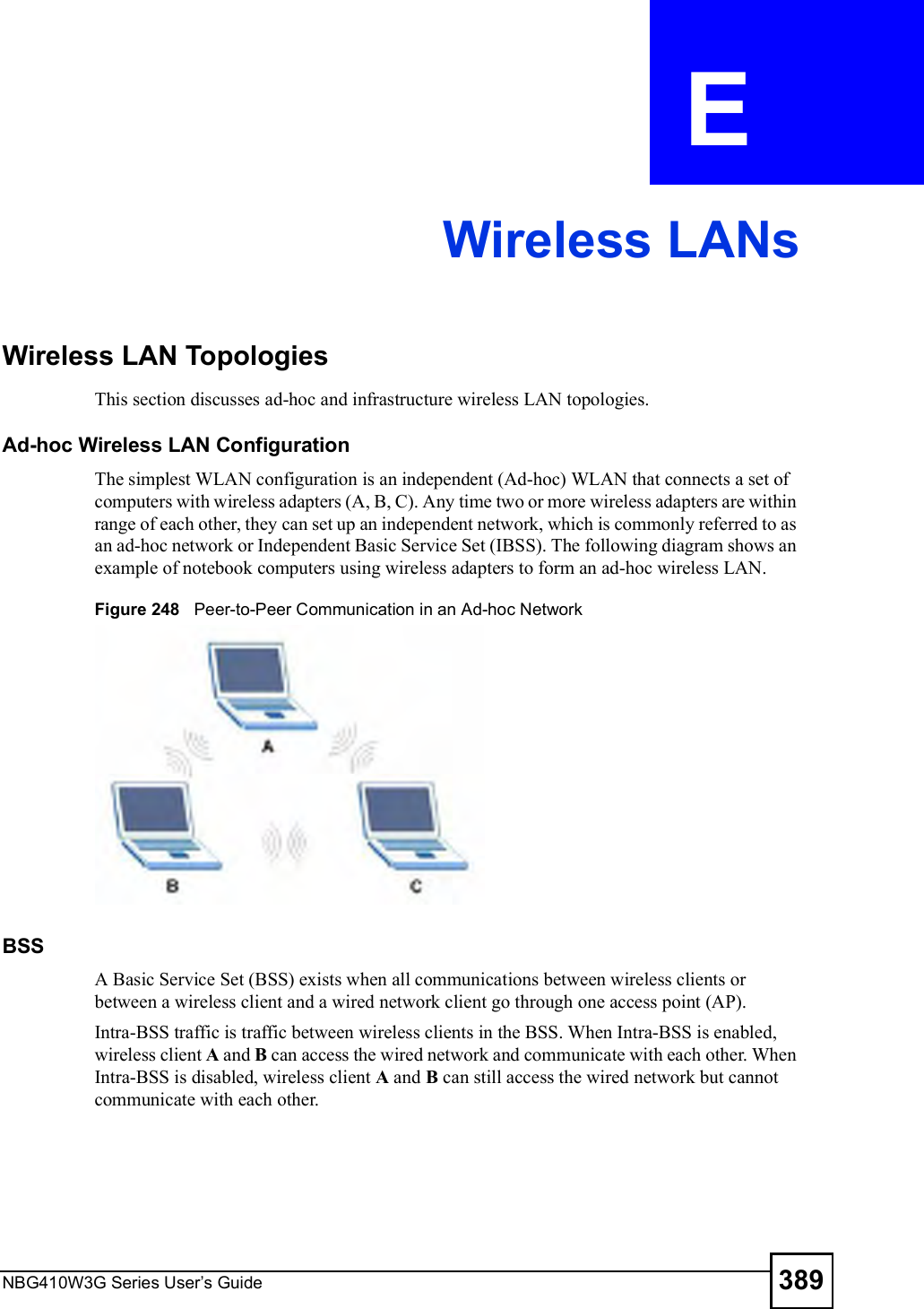
![Chapter 19Logs ScreensNBG410W3G Series User s Guide 317For type and code details, see Table 110 on page 321.Table 106 Attack LogsLOG MESSAGE DESCRIPTIONattack [ TCP | UDP | IGMP | ESP | GRE | OSPF ]The firewall detected a TCP/UDP/IGMP/ESP/GRE/OSPF attack.attack ICMP (type:%d, code:%d)The firewall detected an ICMP attack. land [ TCP | UDP | IGMP | ESP | GRE | OSPF ]The firewall detected a TCP/UDP/IGMP/ESP/GRE/OSPF land attack.land ICMP (type:%d, code:%d)The firewall detected an ICMP land attack. ip spoofing - WAN [ TCP | UDP | IGMP | ESP | GRE | OSPF ]The firewall detected an IP spoofing attack on the WAN port.ip spoofing - WAN ICMP (type:%d, code:%d)The firewall detected an ICMP IP spoofing attack on the WAN port. icmp echo : ICMP (type:%d, code:%d)The firewall detected an ICMP echo attack. syn flood TCP The firewall detected a TCP syn flood attack.ports scan TCP The firewall detected a TCP port scan attack.teardrop TCP The firewall detected a TCP teardrop attack.teardrop UDP The firewall detected an UDP teardrop attack.teardrop ICMP (type:%d, code:%d)The firewall detected an ICMP teardrop attack. illegal command TCP The firewall detected a TCP illegal command attack.NetBIOS TCP The firewall detected a TCP NetBIOS attack.ip spoofing - no routing entry [ TCP | UDP | IGMP | ESP | GRE | OSPF ]The firewall classified a packet with no source routing entry as an IP spoofing attack.ip spoofing - no routing entry ICMP (type:%d, code:%d)The firewall classified an ICMP packet with no source routing entry as an IP spoofing attack.vulnerability ICMP (type:%d, code:%d)The firewall detected an ICMP vulnerability attack. traceroute ICMP (type:%d, code:%d)The firewall detected an ICMP traceroute attack. ports scan UDP The firewall detected a UDP port scan attack.Firewall sent TCP packet in response to DoS attack TCPThe firewall sent TCP packet in response to a DoS attackICMP Source Quench ICMP The firewall detected an ICMP Source Quench attack.ICMP Time Exceed ICMP The firewall detected an ICMP Time Exceed attack.ICMP Destination Unreachable ICMPThe firewall detected an ICMP Destination Unreachable attack.ping of death. ICMP The firewall detected an ICMP ping of death attack.smurf ICMP The firewall detected an ICMP smurf attack.](https://usermanual.wiki/ZyXEL-Communications/NBG410W3G.User-manual-2-rev2/User-Guide-986480-Page-117.png)

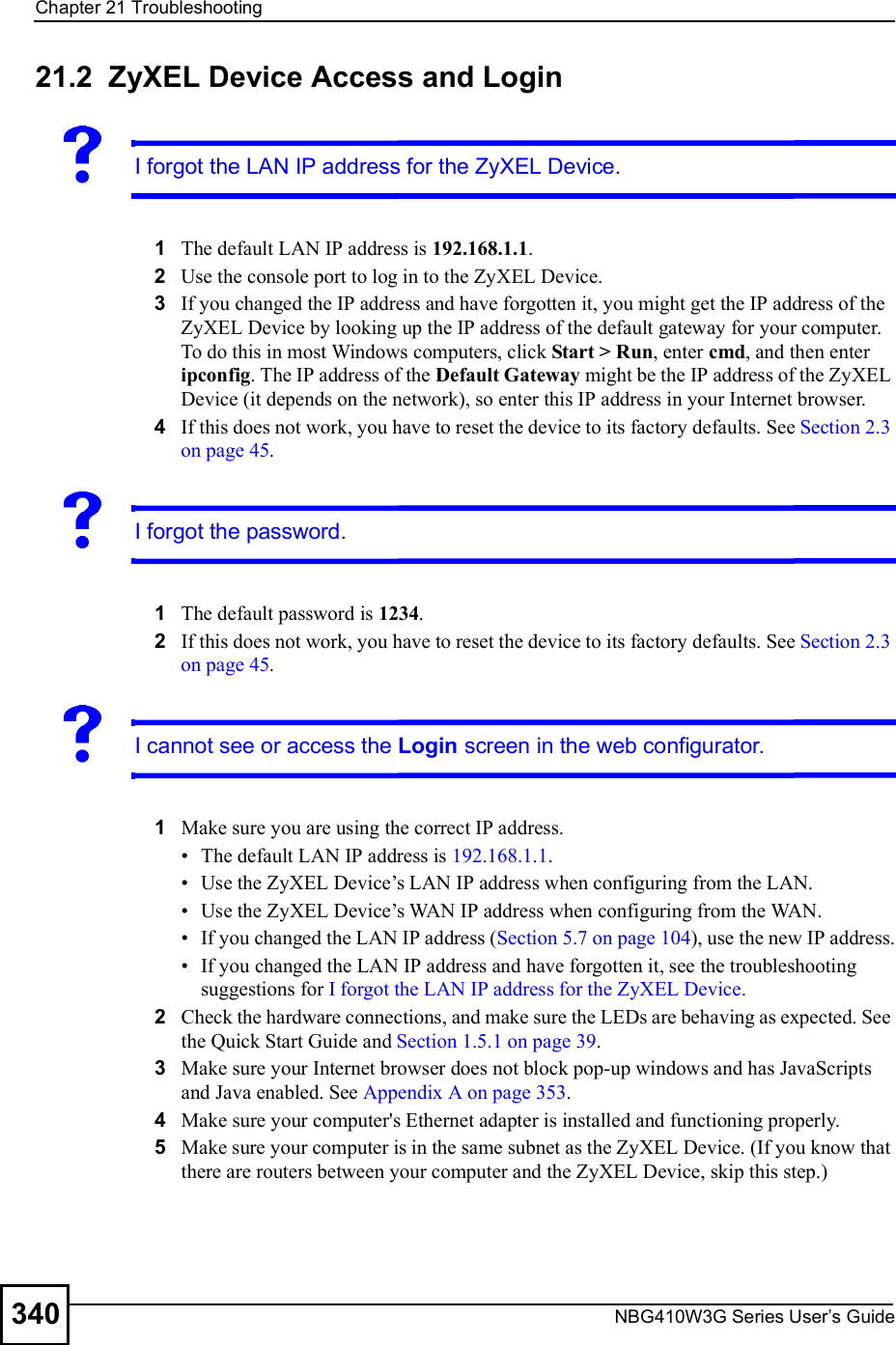
![Chapter 21TroubleshootingNBG410W3G Series User s Guide 341 If there is a DHCP server on your network, make sure your computer is using a dynamic IP address. See Appendix B on page 361. Your ZyXEL Device is a DHCP server by default. 6Reset the device to its factory defaults, and try to access the ZyXEL Device with the default IP address. See Section 2.3 on page 45. 7If the problem continues, contact the network administrator or vendor, or try one of the advanced suggestions.Advanced Suggestions Try to access the ZyXEL Device using another service, such as Telnet. If you can access the ZyXEL Device, check the remote management settings, and firewall rules to find out why the ZyXEL Device does not respond to HTTP. If your computer is connected to the WAN port or is connected wirelessly, use a computer that is connected to a LAN port. You may also need to clear your Internet browser!s cache.In Internet Explorer, click Tools and then Internet Options to open the Internet Options screen. In the General tab, click Delete Files. In the pop-up window, select the Delete all offline content check box and click OK. Click OK in the Internet Options screen to close it. If you disconnect your computer from one device and connect it to another device that has the same IP address, your computer!s ARP (Address Resolution Protocol) table may contain an entry that maps the management IP address to the previous device!s MAC address). In Windows, use arp -d at the command prompt to delete all entries in your computer!s ARP table.I can see the Login screen, but I cannot log in to the ZyXEL Device.1Make sure you have entered the password correctly. The default password is 1234. These fields are case-sensitive, so make sure [Caps Lock] is not on. 2You cannot log in to the web configurator while someone is using Telnet, or the console port to access the ZyXEL Device. Log out of the ZyXEL Device in the other session, or ask the person who is logged in to log out.3Turn the ZyXEL Device off and on or disconnect and re-connect the power adaptor or cord to the ZyXEL Device. 4If this does not work, you have to reset the device to its factory defaults. See Section 2.3 on page 45.I cannot Telnet to the ZyXEL Device.See the troubleshooting suggestions for I cannot see or access the Login screen in the web configurator. Ignore the suggestions about your browser.](https://usermanual.wiki/ZyXEL-Communications/NBG410W3G.User-manual-2-rev2/User-Guide-986480-Page-141.png)
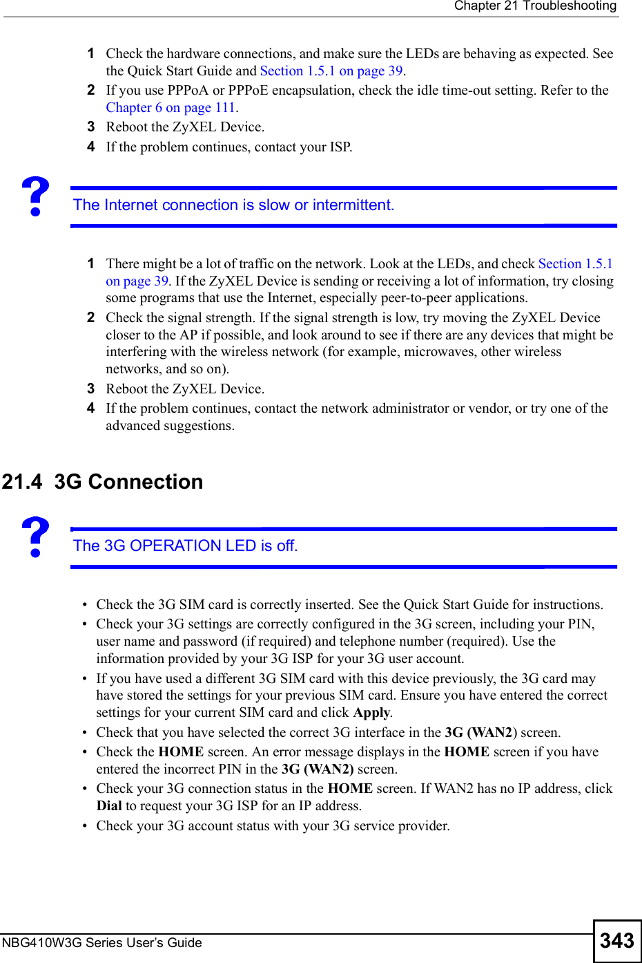
![Chapter 21TroubleshootingNBG410W3G Series User s Guide342I cannot use FTP to upload / download the configuration file. / I cannot use FTP to upload new firmware. See the troubleshooting suggestions for I cannot see or access the Login screen in the web configurator. Ignore the suggestions about your browser.21.3 Internet AccessI cannot get a WAN IP address from the ISP.1The ISP provides the WAN IP address after authenticating you. Authentication may be through the user name and password, the MAC address or the host name.The username and password apply to PPPoE and PPPoA encapsulation only. Make sure that you have entered the correct Service Type, User Name and Password (be sure to use the correct casing). Refer to the WAN setup chapter (web configurator).2Disconnect all the cables from your device, and follow the directions in the Quick Start Guide again. 3If the problem continues, contact your ISP.I cannot access the Internet.1Check the hardware connections, and make sure the LEDs are behaving as expected. See the Quick Start Guide and Section 1.5.1 on page 39.2Make sure you entered your ISP account information correctly in the wizard, or WAN screen. These fields are case-sensitive, so make sure [Caps Lock] is not on. 3If you are trying to access the Internet wirelessly, make sure the wireless settings in the wireless client are the same as the settings in the AP. 4Disconnect all the cables from your device, and follow the directions in the Quick Start Guide again. 5If the problem continues, contact your ISP. I cannot access the Internet anymore. I had access to the Internet (with the ZyXEL Device), but my Internet connection is not available anymore.](https://usermanual.wiki/ZyXEL-Communications/NBG410W3G.User-manual-2-rev2/User-Guide-986480-Page-142.png)


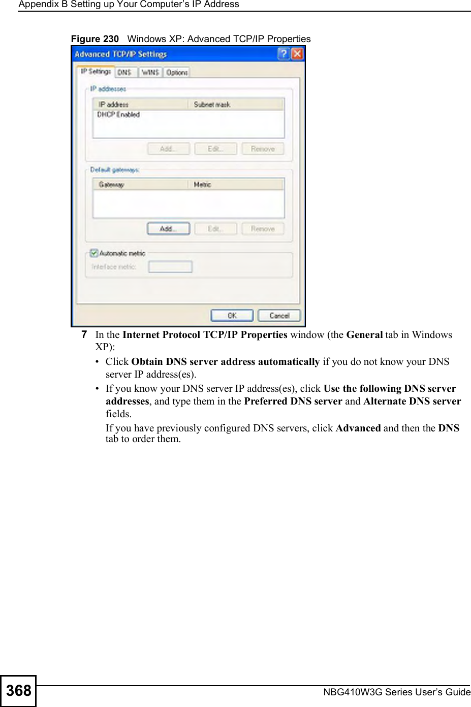
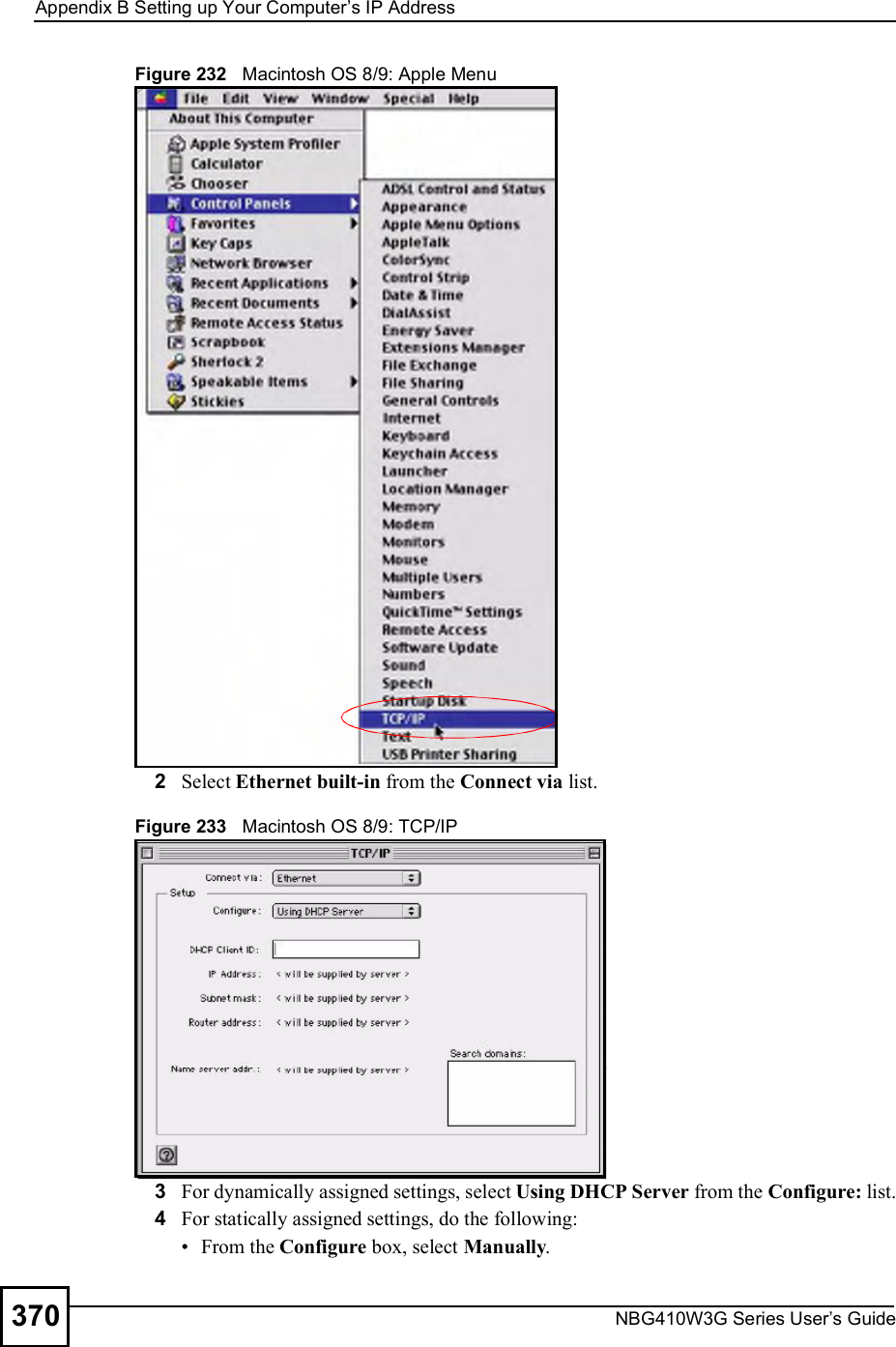
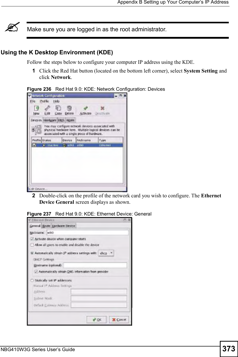
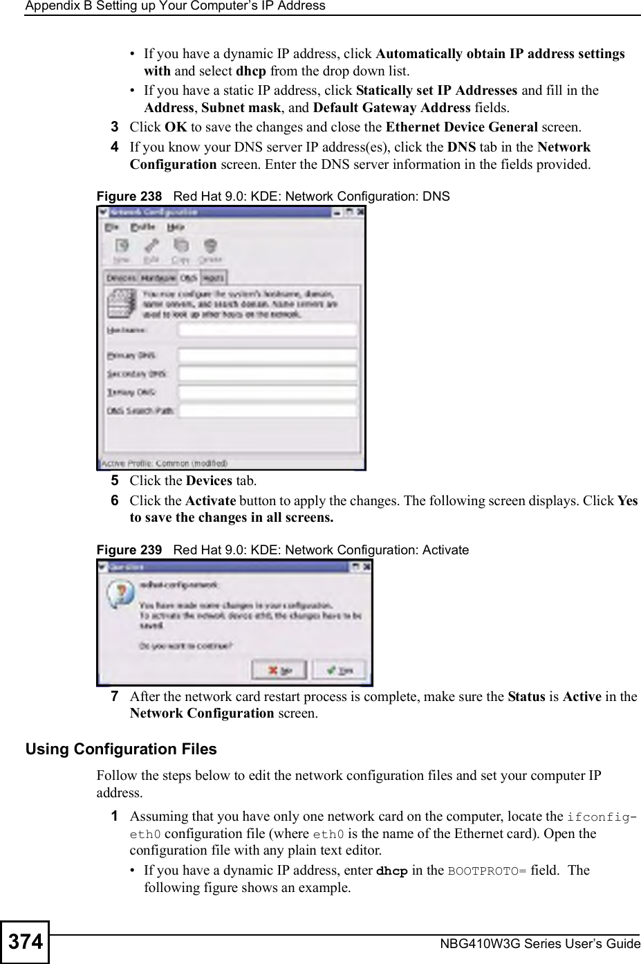
![Appendix BSetting up Your Computer s IP AddressNBG410W3G Series User s Guide 369Figure 231 Windows XP: Internet Protocol (TCP/IP) Properties8Click OK to close the Internet Protocol (TCP/IP) Properties window.9Click Close (OK in Windows 2000/NT) to close the Local Area Connection Properties window.10 Close the Network Connections window (Network and Dial-up Connections in Windows 2000/NT).11 Turn on your ZyXEL Device and restart your computer (if prompted).Verifying Settings1Click Start, All Programs, Accessories and then Command Prompt.2In the Command Prompt window, type "ipconfig" and then press [ENTER]. You can also open Network Connections, right-click a network connection, click Status and then click the Support tab.Macintosh OS 8/9 1Click the Apple menu, Control Panel and double-click TCP/IP to open the TCP/IP Control Panel.](https://usermanual.wiki/ZyXEL-Communications/NBG410W3G.User-manual-2-rev2/User-Guide-986480-Page-169.png)
![Appendix BSetting up Your Computer s IP AddressNBG410W3G Series User s Guide 375Figure 240 Red Hat 9.0: Dynamic IP Address Setting in ifconfig-eth0 If you have a static IP address, enter static in the BOOTPROTO= field. Type IPADDR= followed by the IP address (in dotted decimal notation) and type NETMASK= followed by the subnet mask. The following example shows an example where the static IP address is 192.168.1.10 and the subnet mask is 255.255.255.0. Figure 241 Red Hat 9.0: Static IP Address Setting in ifconfig-eth0 2If you know your DNS server IP address(es), enter the DNS server information in the resolv.conf file in the /etc directory. The following figure shows an example where two DNS server IP addresses are specified.Figure 242 Red Hat 9.0: DNS Settings in resolv.conf 3After you edit and save the configuration files, you must restart the network card. Enter ./network restart in the /etc/rc.d/init.d directory. The following figure shows an example.Figure 243 Red Hat 9.0: Restart Ethernet Card DEVICE=eth0ONBOOT=yesBOOTPROTO=dhcpUSERCTL=noPEERDNS=yesTYPE=EthernetDEVICE=eth0ONBOOT=yesBOOTPROTO=staticIPADDR=192.168.1.10NETMASK=255.255.255.0USERCTL=noPEERDNS=yesTYPE=Ethernetnameserver 172.23.5.1nameserver 172.23.5.2[root@localhost init.d]# network restartShutting down interface eth0: [OK]Shutting down loopback interface: [OK]Setting network parameters: [OK]Bringing up loopback interface: [OK]Bringing up interface eth0: [OK]](https://usermanual.wiki/ZyXEL-Communications/NBG410W3G.User-manual-2-rev2/User-Guide-986480-Page-175.png)
![Appendix BSetting up Your Computer s IP AddressNBG410W3G Series User s Guide376Verifying SettingsEnter ifconfig in a terminal screen to check your TCP/IP properties. Figure 244 Red Hat 9.0: Checking TCP/IP Properties [root@localhost]# ifconfig eth0 Link encap:Ethernet HWaddr 00:50:BA:72:5B:44 inet addr:172.23.19.129 Bcast:172.23.19.255 Mask:255.255.255.0 UP BROADCAST RUNNING MULTICAST MTU:1500 Metric:1 RX packets:717 errors:0 dropped:0 overruns:0 frame:0 TX packets:13 errors:0 dropped:0 overruns:0 carrier:0 collisions:0 txqueuelen:100 RX bytes:730412 (713.2 Kb) TX bytes:1570 (1.5 Kb) Interrupt:10 Base address:0x1000 [root@localhost]#](https://usermanual.wiki/ZyXEL-Communications/NBG410W3G.User-manual-2-rev2/User-Guide-986480-Page-176.png)