ZyXEL Communications NBG417N Wireless N-LITE 3G Router User Manual 3890293
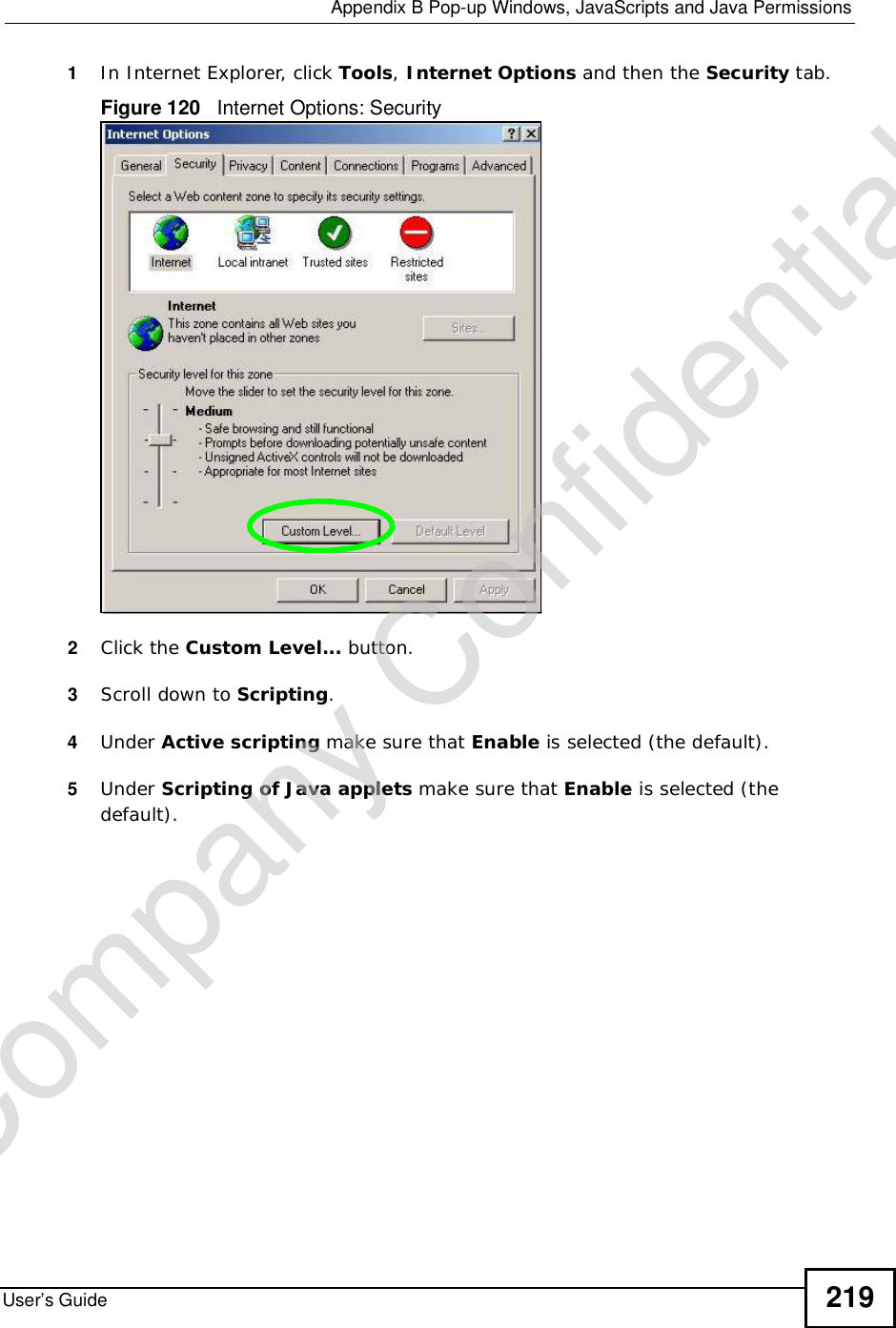
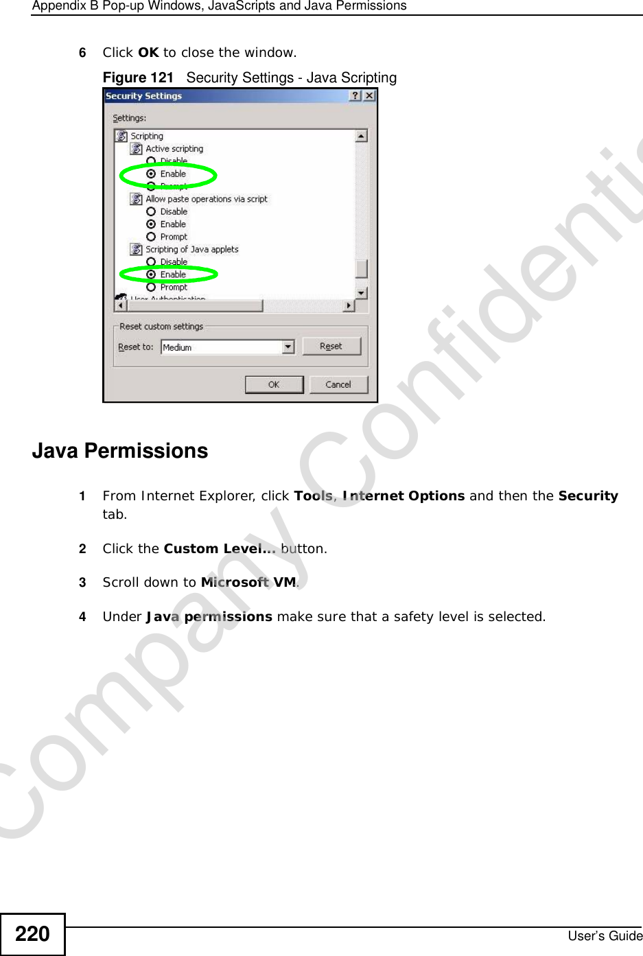
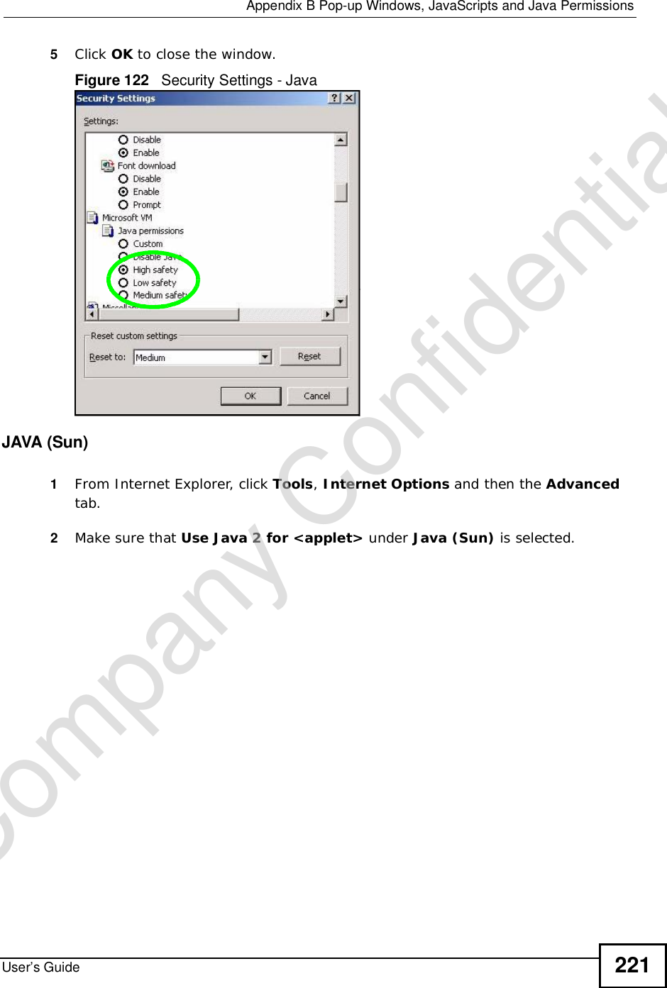
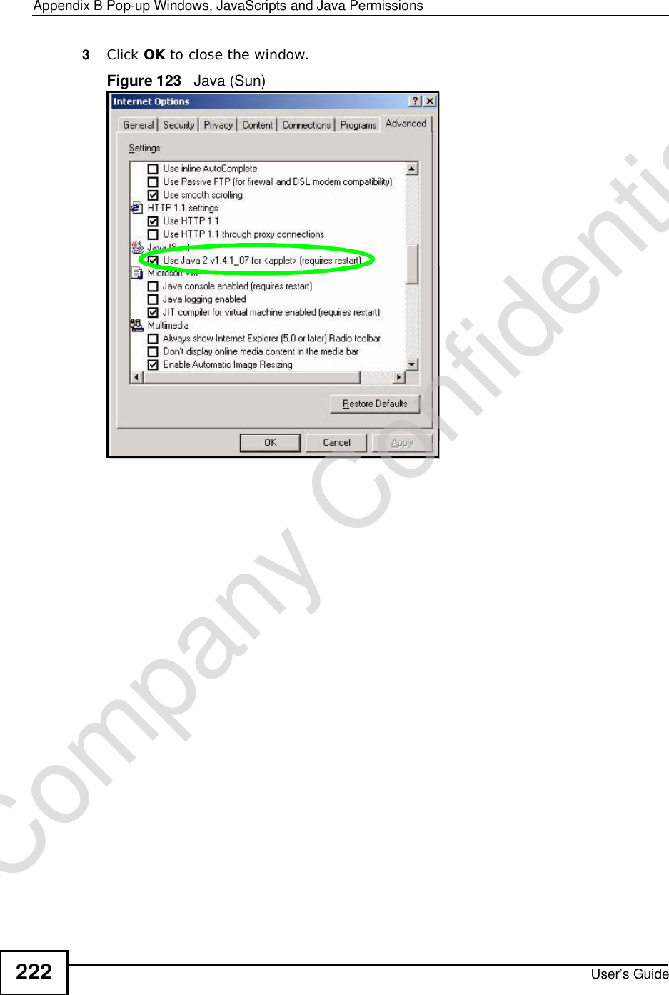
ZyXEL Communications Corporation Wireless N-LITE 3G Router 3890293
UserManual.wiki
>
ZyXEL Communications
>
NBG417N User Manual
>
User Manual
Contents
1.
Manual
2.
User Manual
User Manual
Navigation menu
Upload a User Manual
Namespaces
Wiki Guide
HTML
PDF
Info
Views
User Manual
Discussion / Help
Navigation
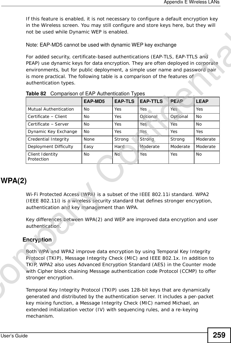
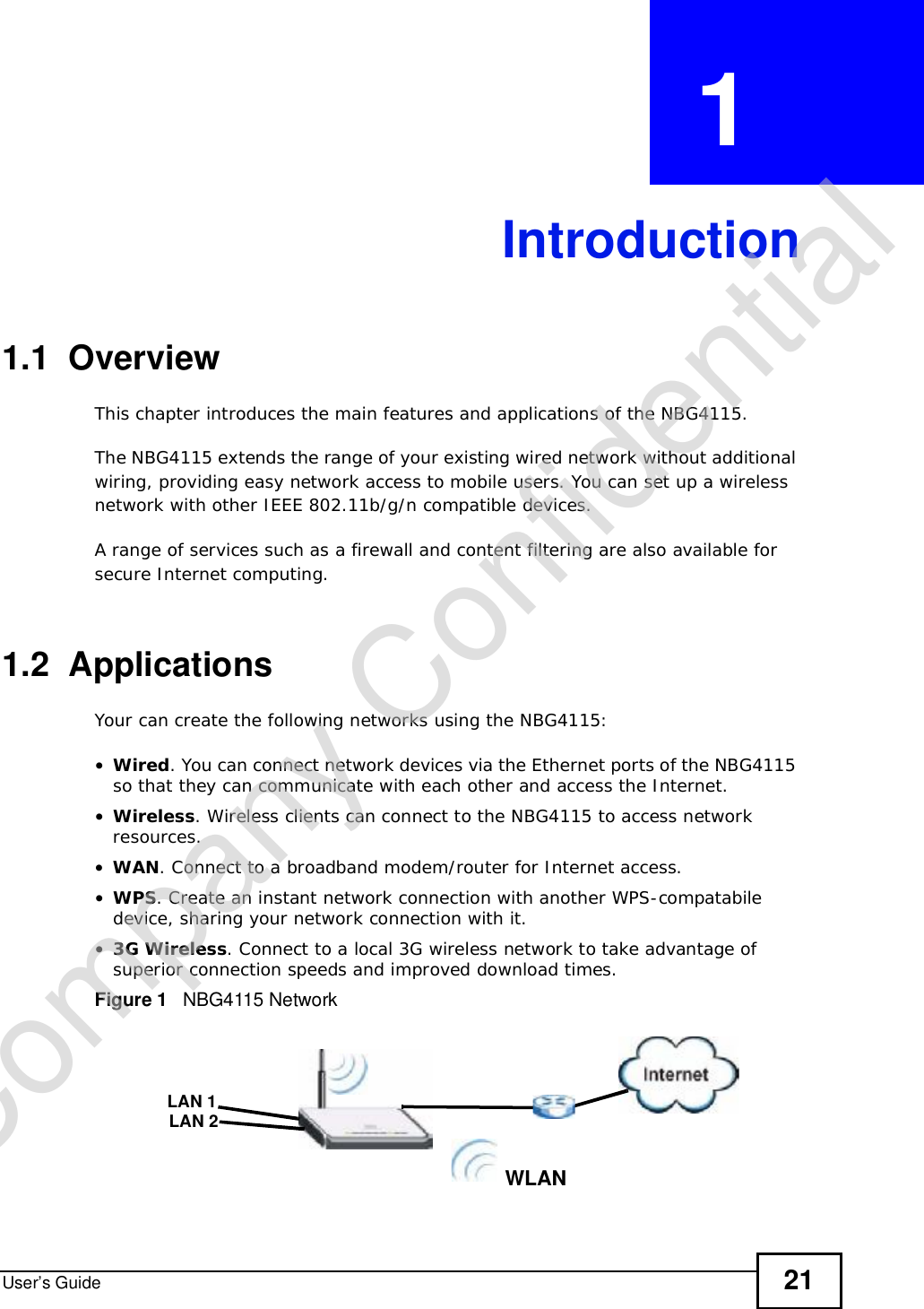
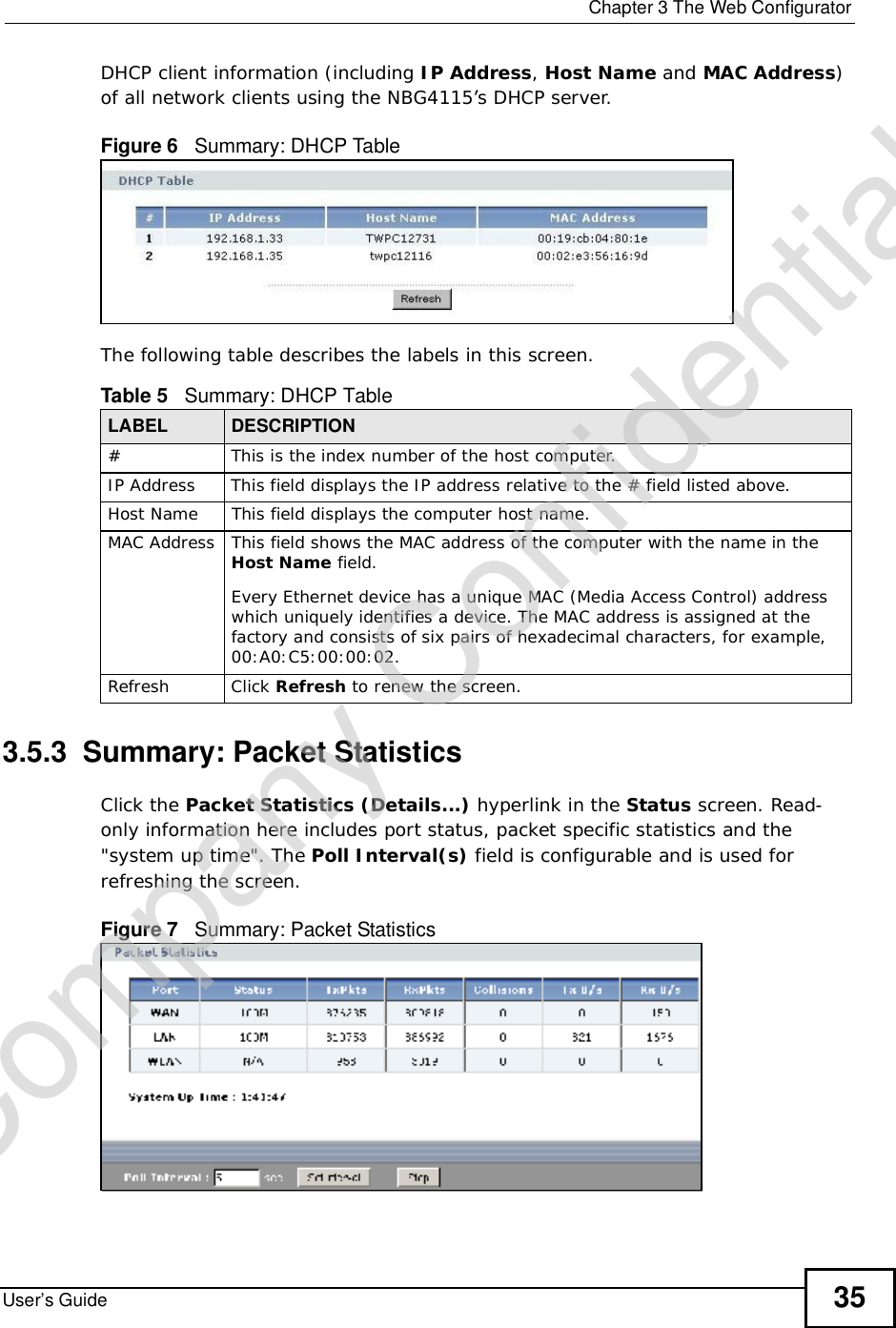
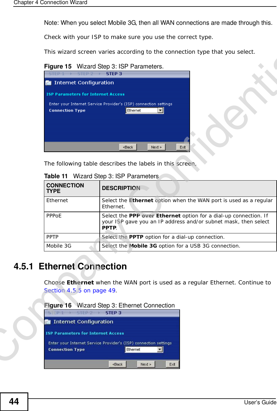
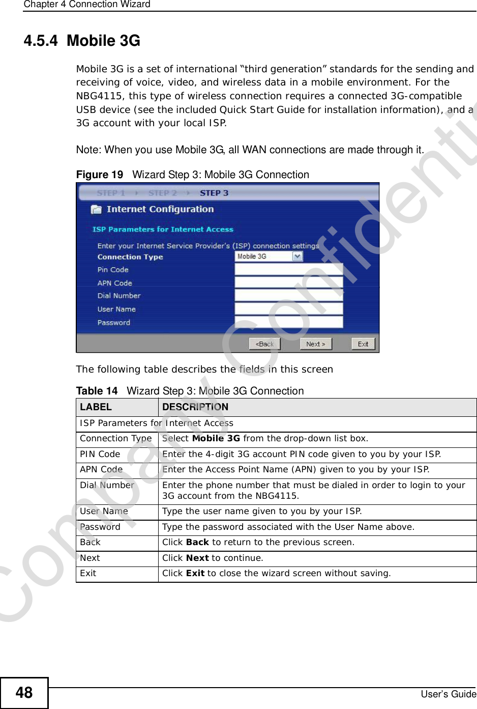
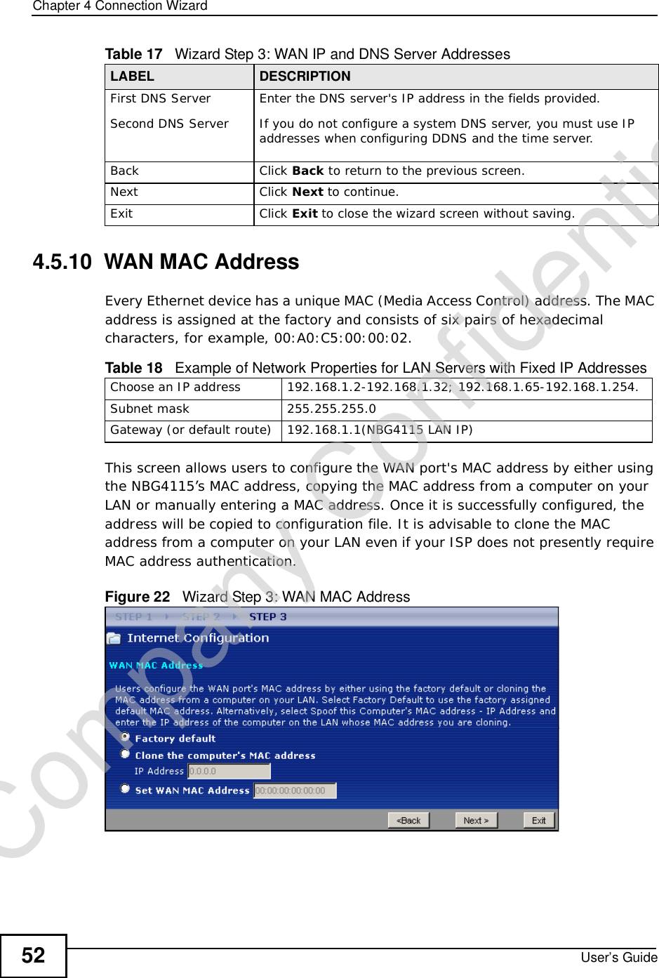
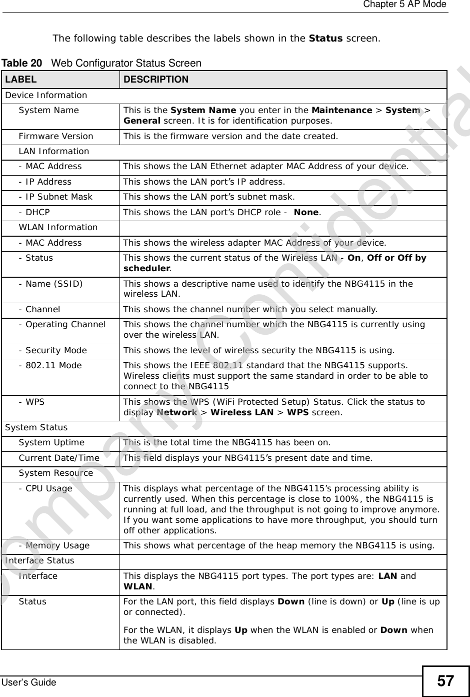
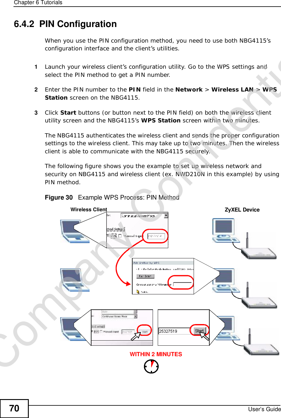
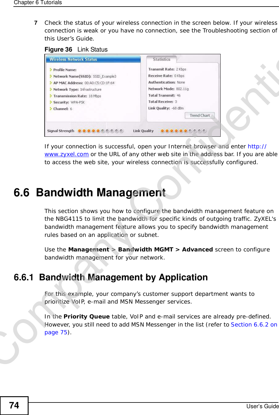
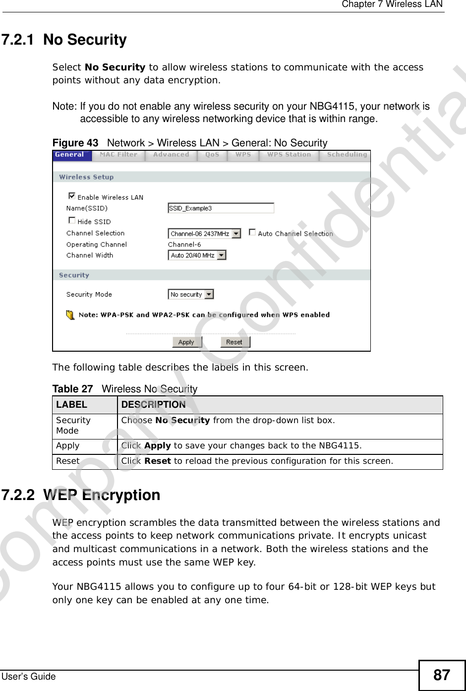
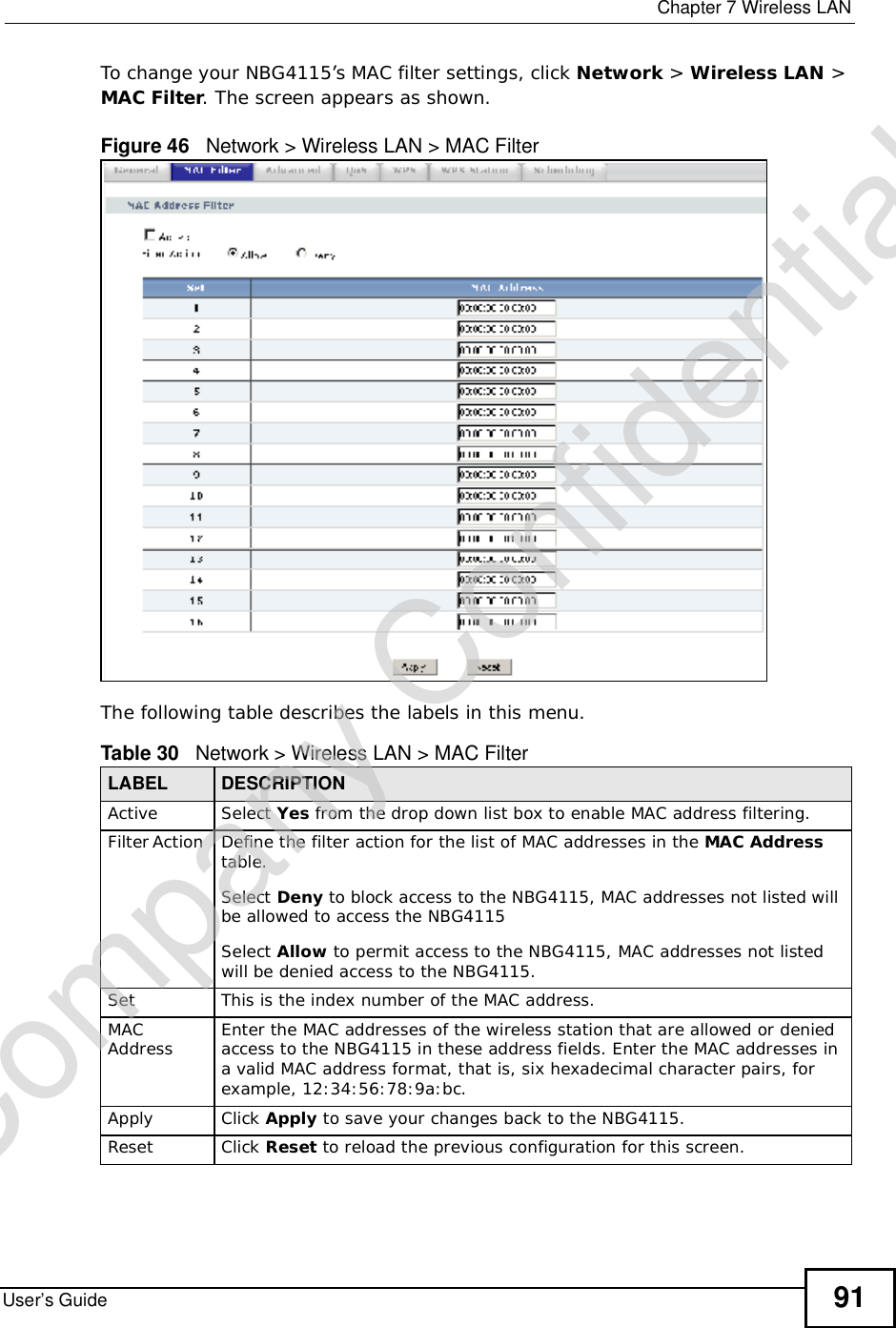
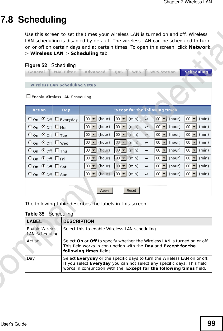
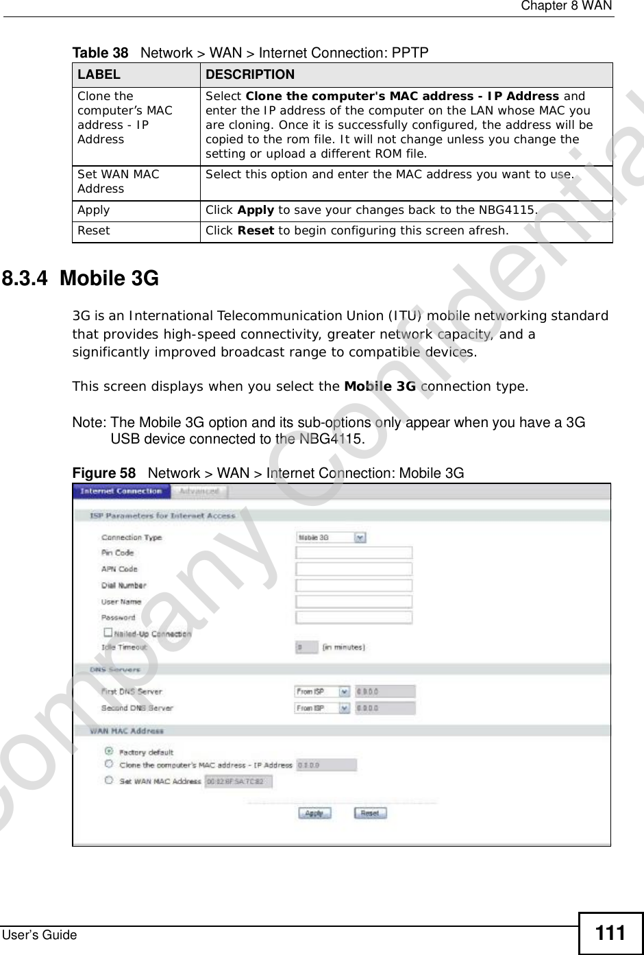
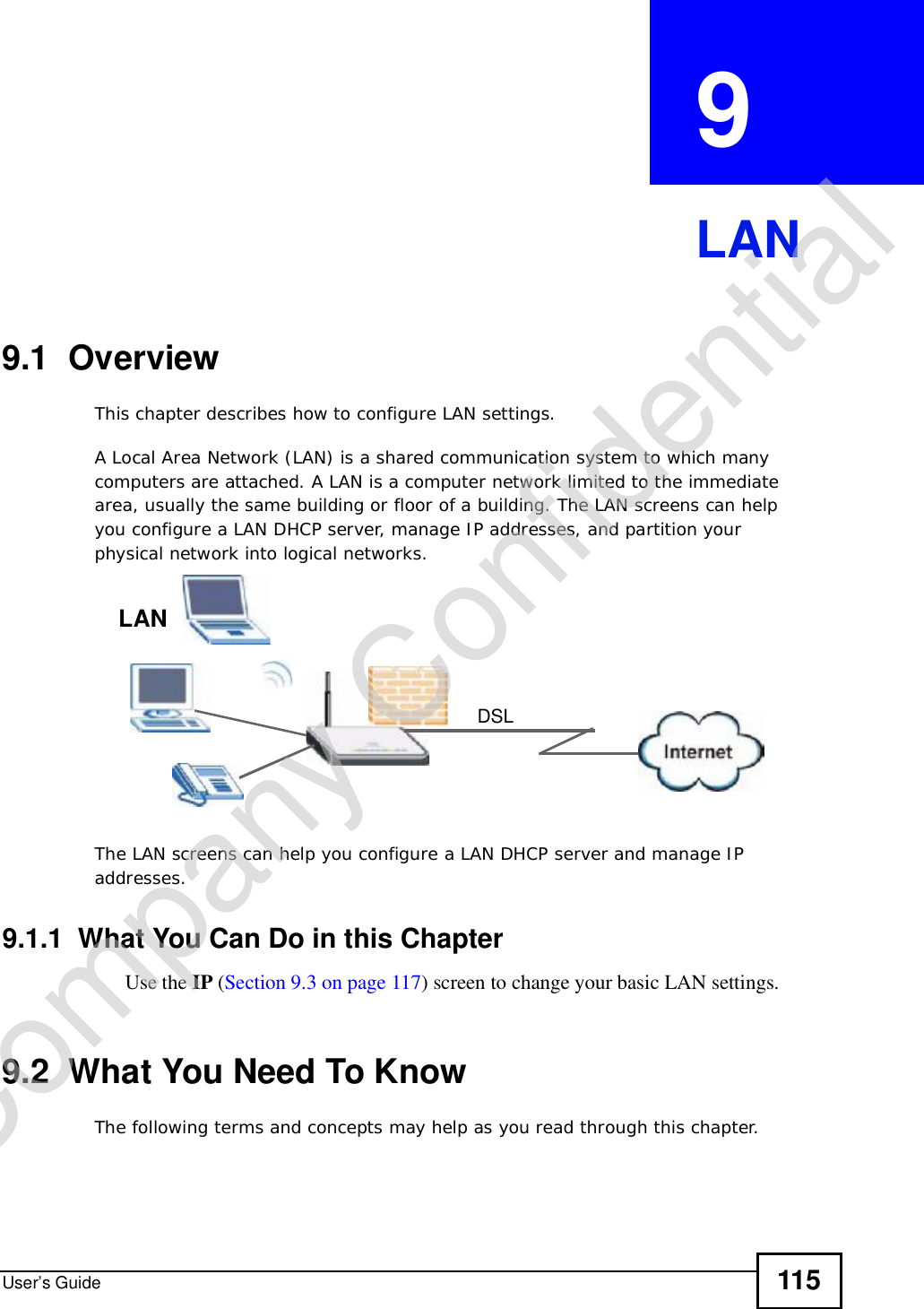
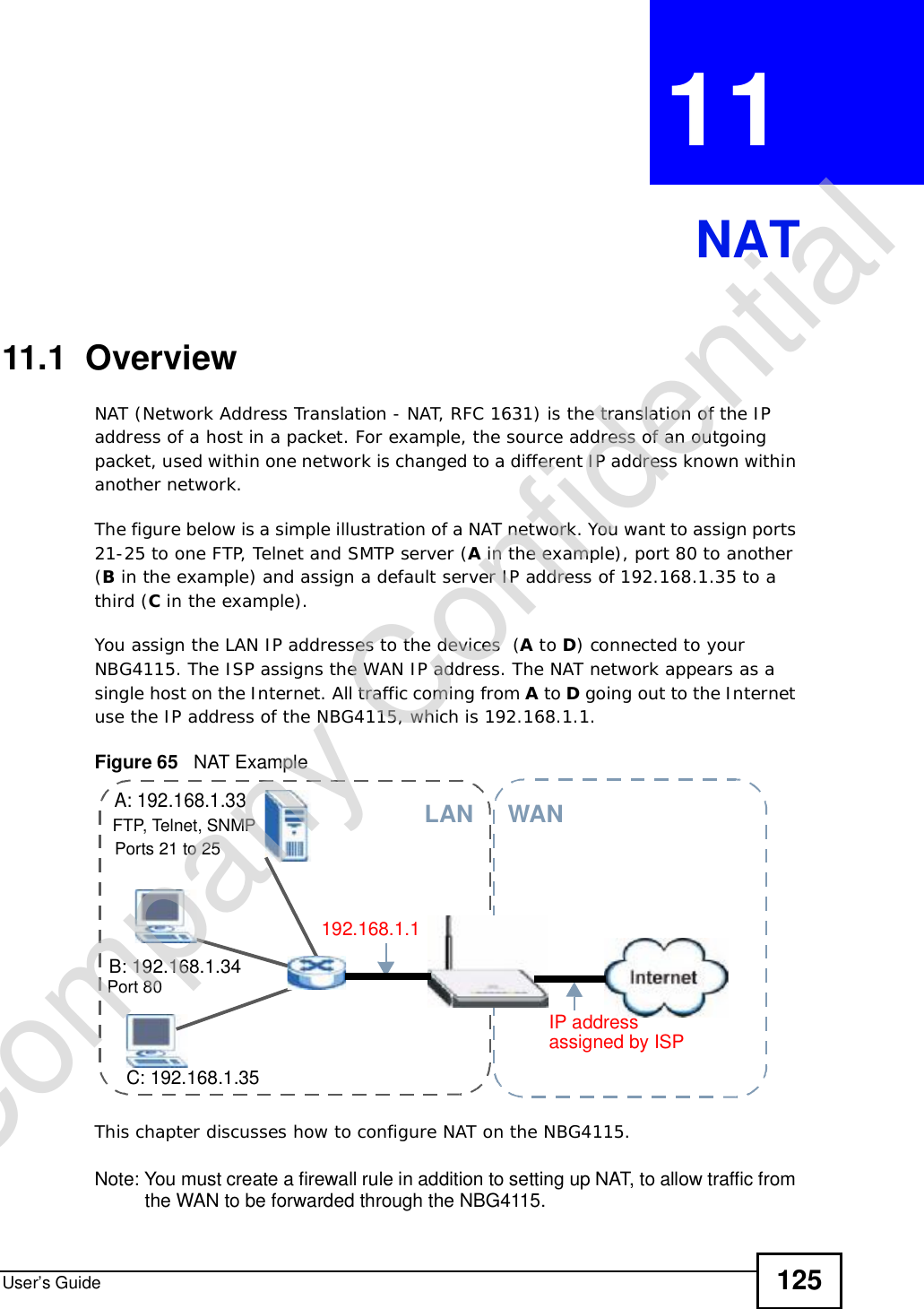
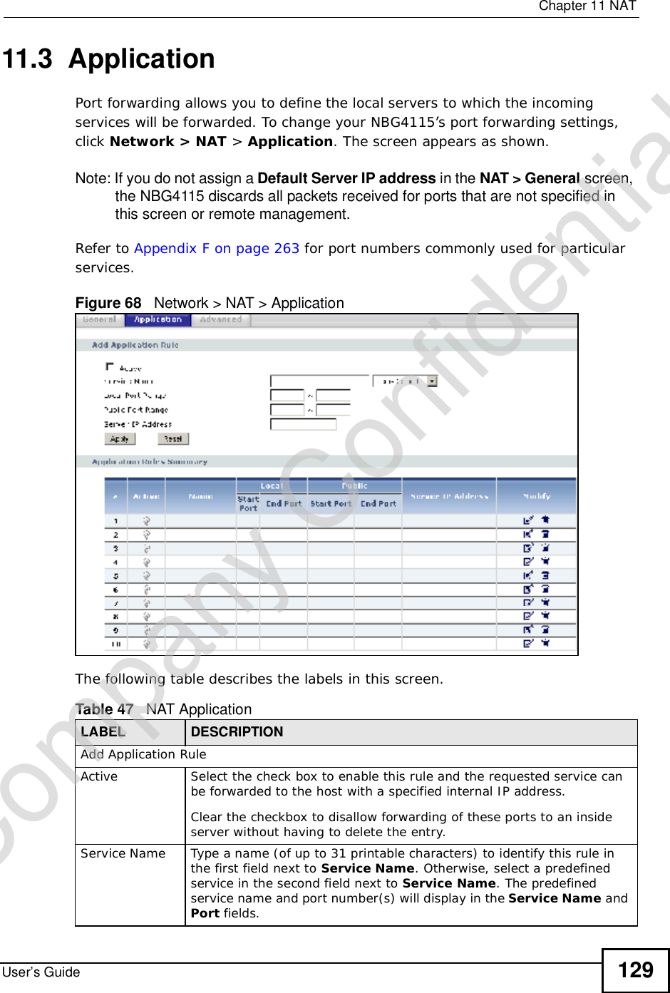
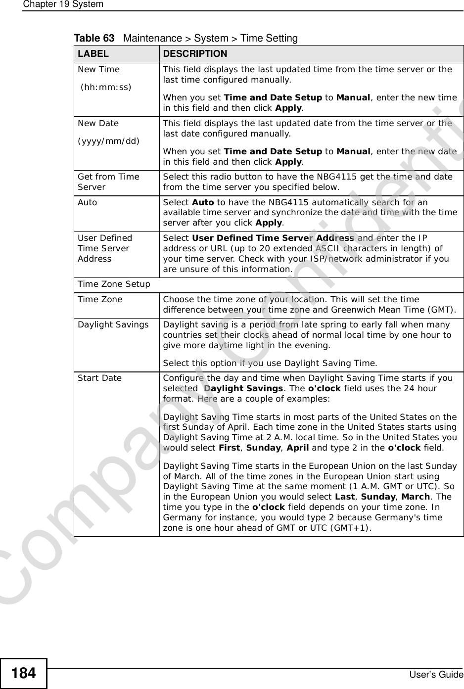
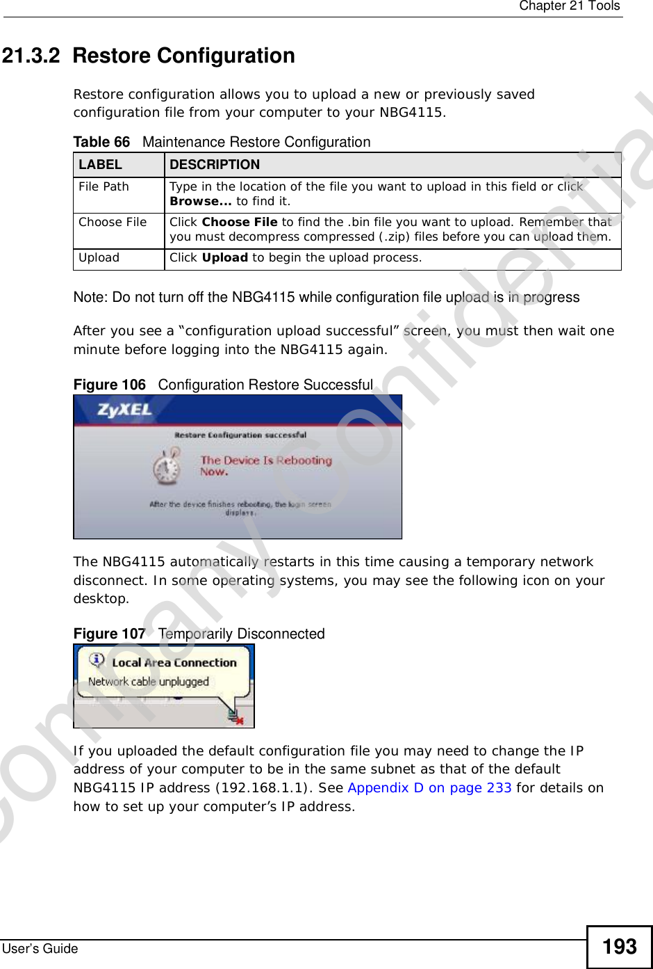
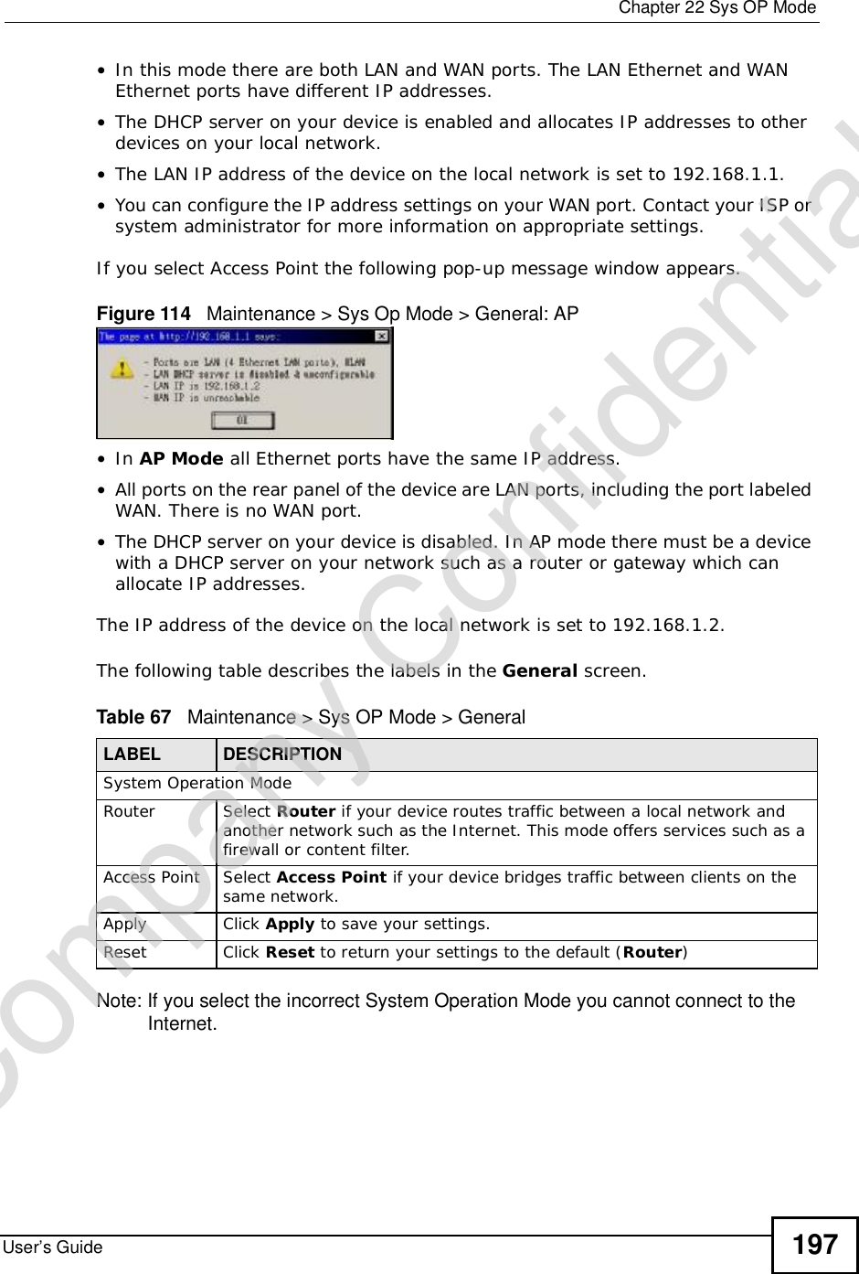
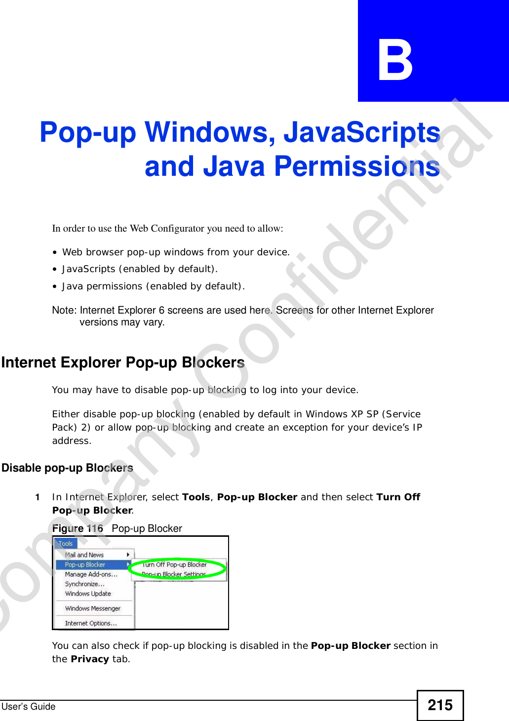
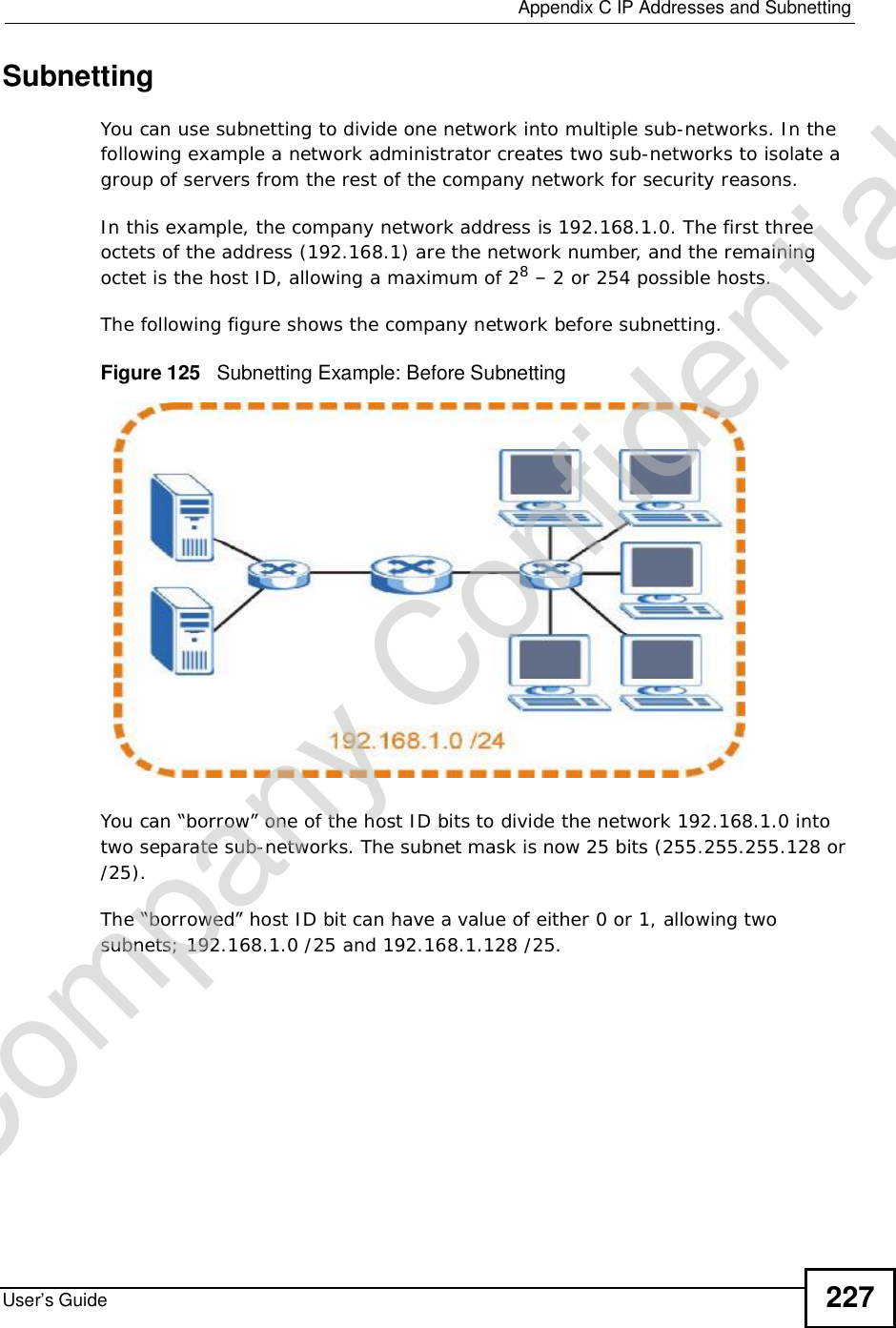
![About This User's GuideUser’s Guide 3About This User's GuideIntended AudienceThis manual is intended for people who want to configure the NBG4115 using the Web Configurator. You should have at least a basic knowledge of TCP/IP networking concepts and topology.Tips for Reading User’s Guides On-ScreenWhen reading a ZyXEL User’s Guide On-Screen, keep the following in mind:•If you don’t already have the latest version of Adobe Reader, you can download it from http://www.adobe.com.•Use the PDF’s bookmarks to quickly navigate to the areas that interest you. Adobe Reader’s bookmarks pane opens by default in all ZyXEL User’s Guide PDFs.•If you know the page number or know vaguely which page-range you want to view, you can enter a number in the toolbar in Reader, then press [ENTER] to jump directly to that page.•Type [CTRL]+[F] to open the Adobe Reader search utility and enter a word or phrase. This can help you quickly pinpoint the information you require. You can also enter text directly into the toolbar in Reader.•To quickly move around within a page, press the [SPACE] bar. This turns your cursor into a “hand” with which you can grab the page and move it around freely on your screen.•Embedded hyperlinks are actually cross-references to related text. Click them to jump to the corresponding section of the User’s Guide PDF.Related Documentation•Quick Start Guide The Quick Start Guide is designed to help you get your NBG4115 up and running right away. It contains information on setting up your network and configuring for Internet access.•Supporting DiscThe embedded Web Help contains descriptions of individual screens and supplementary information.•Support DiscRefer to the included CD for support documents.Company Confidential](https://usermanual.wiki/ZyXEL-Communications/NBG417N.User-Manual/User-Guide-1164748-Page-2.png)
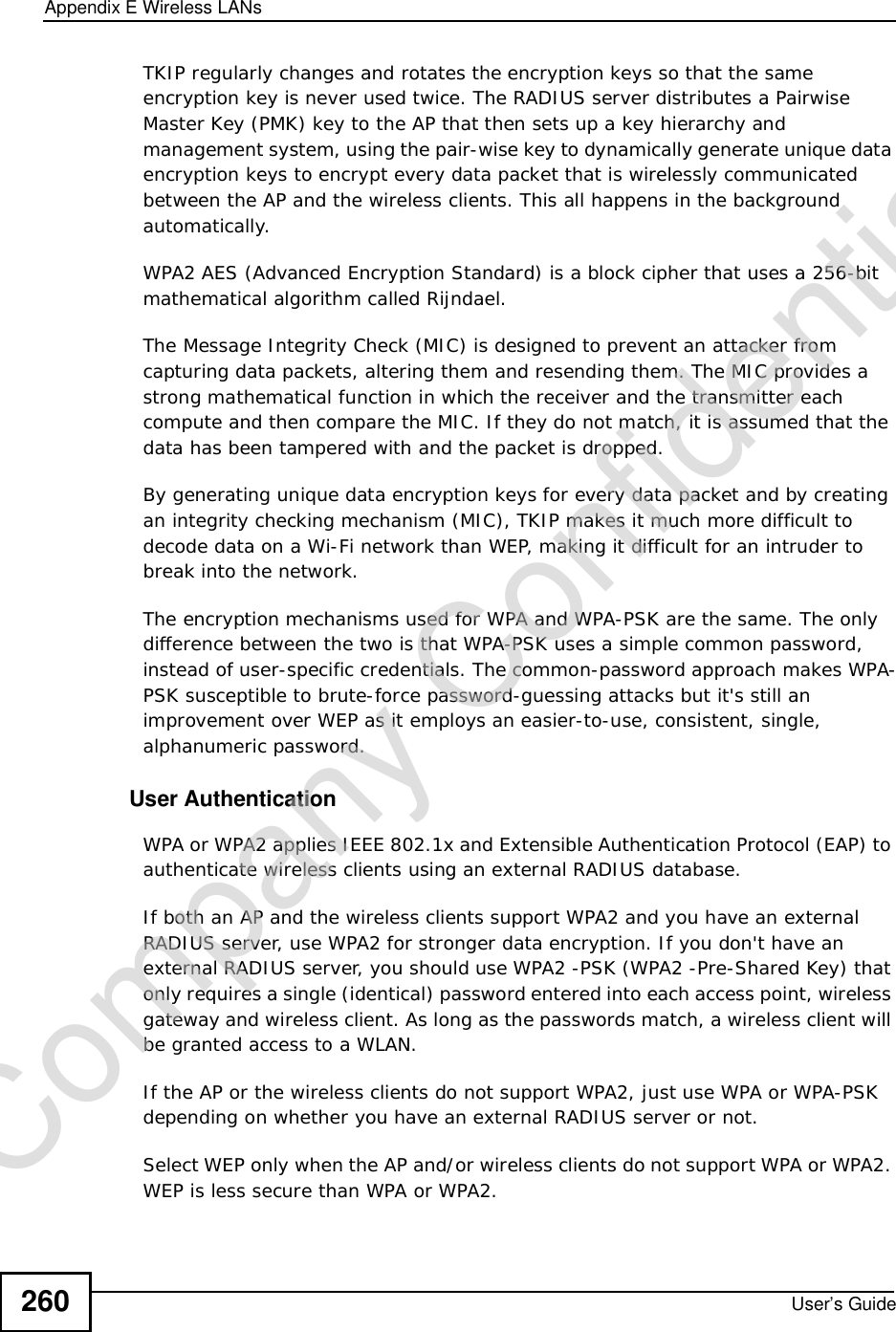
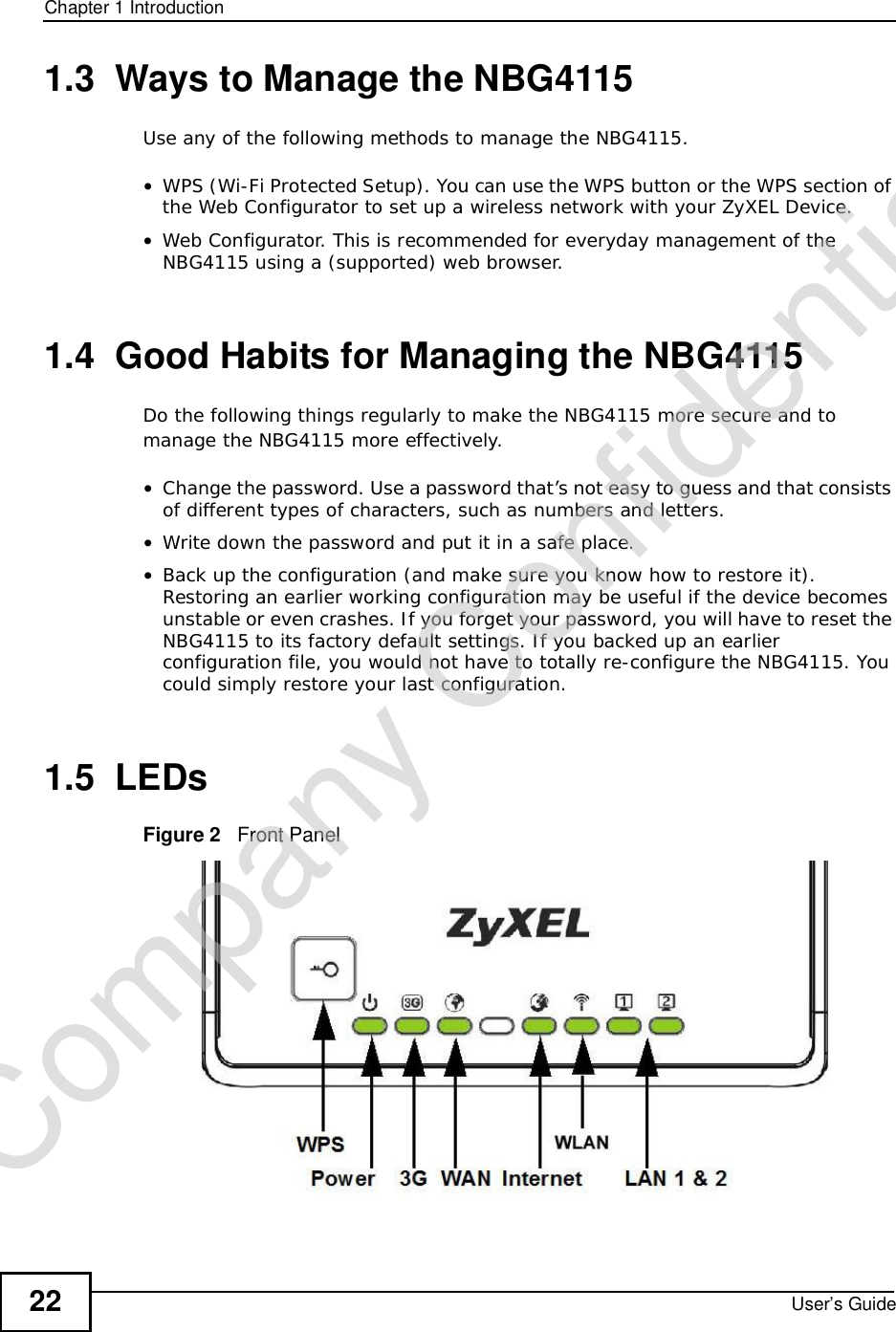
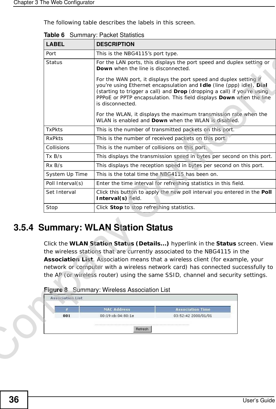
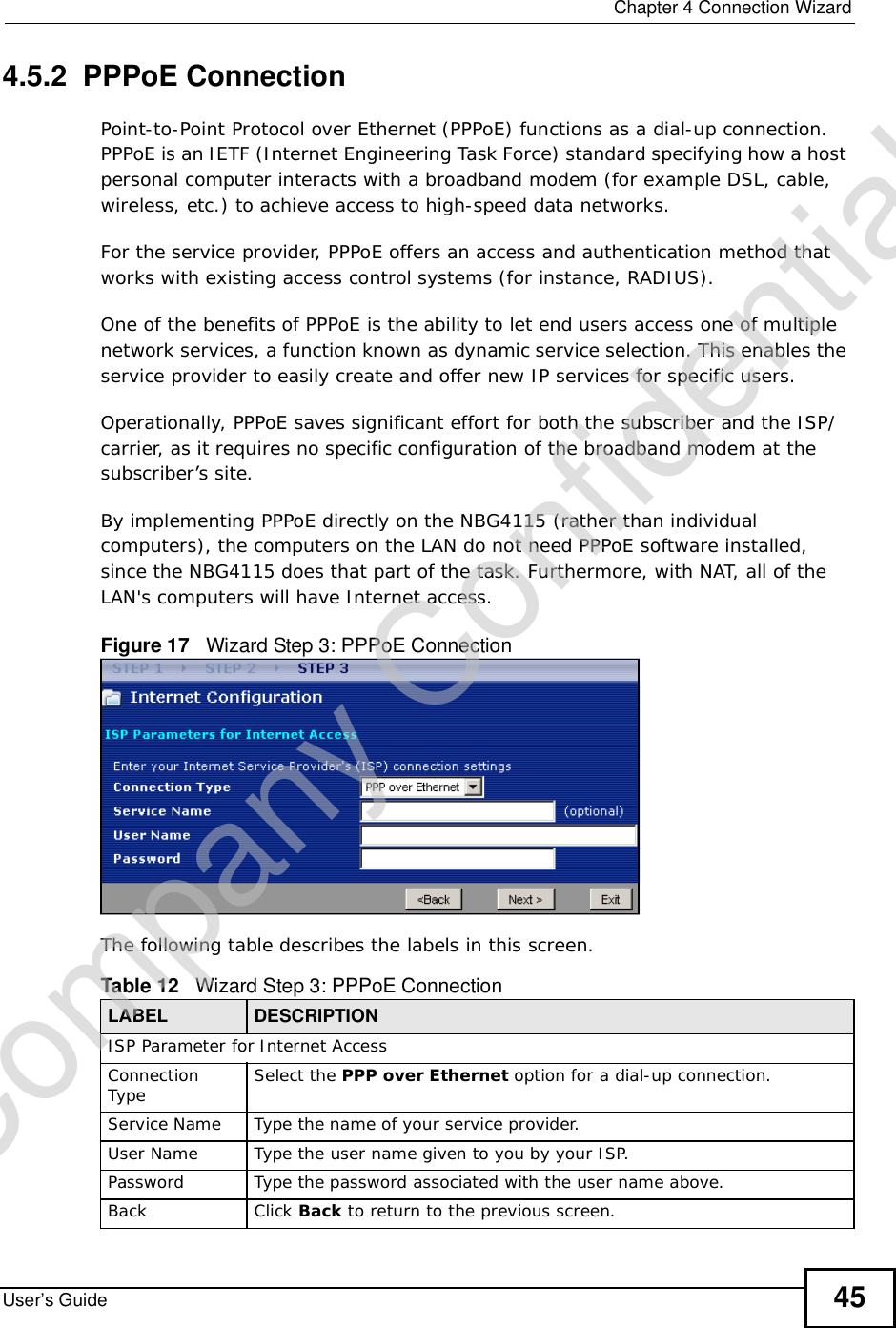
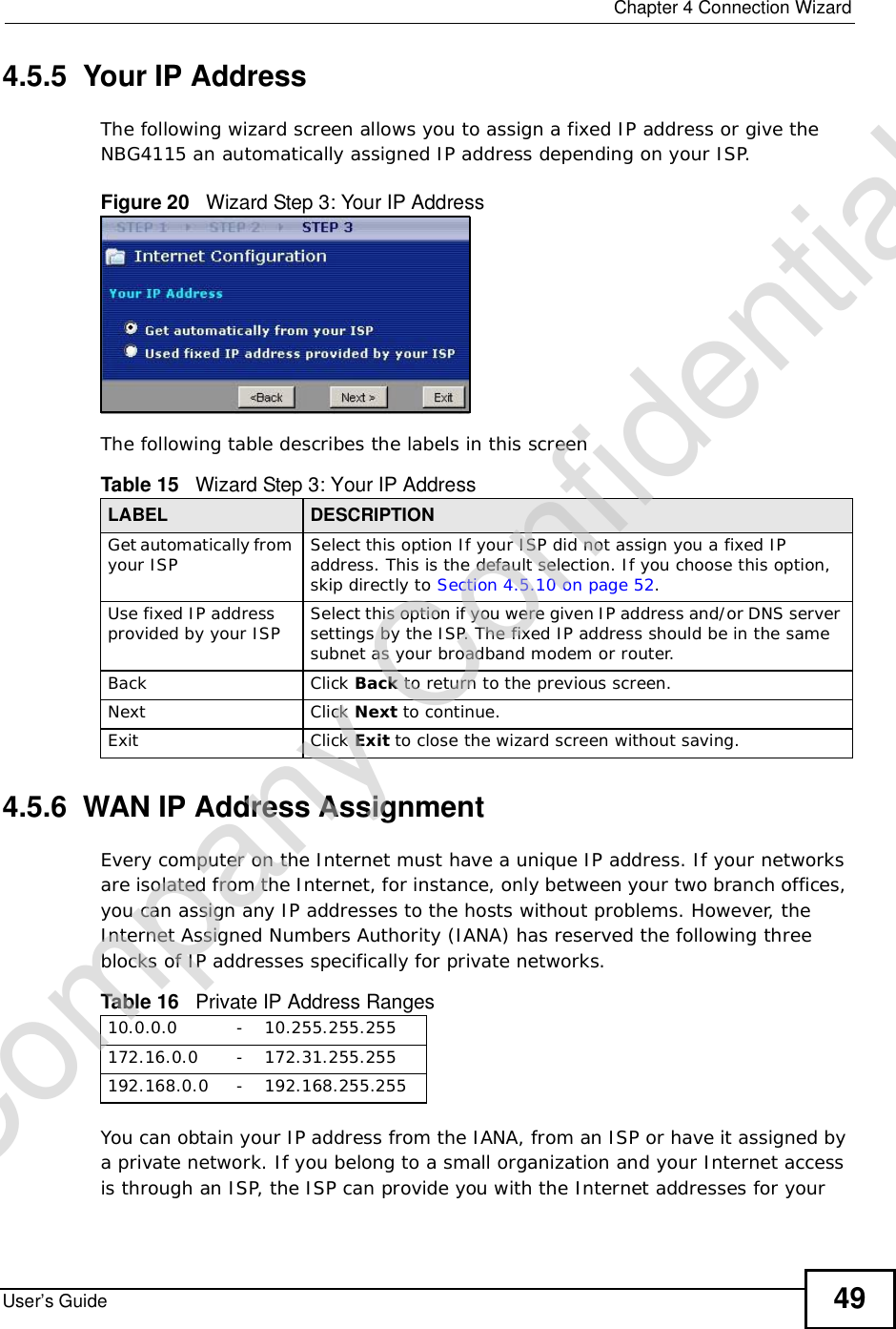
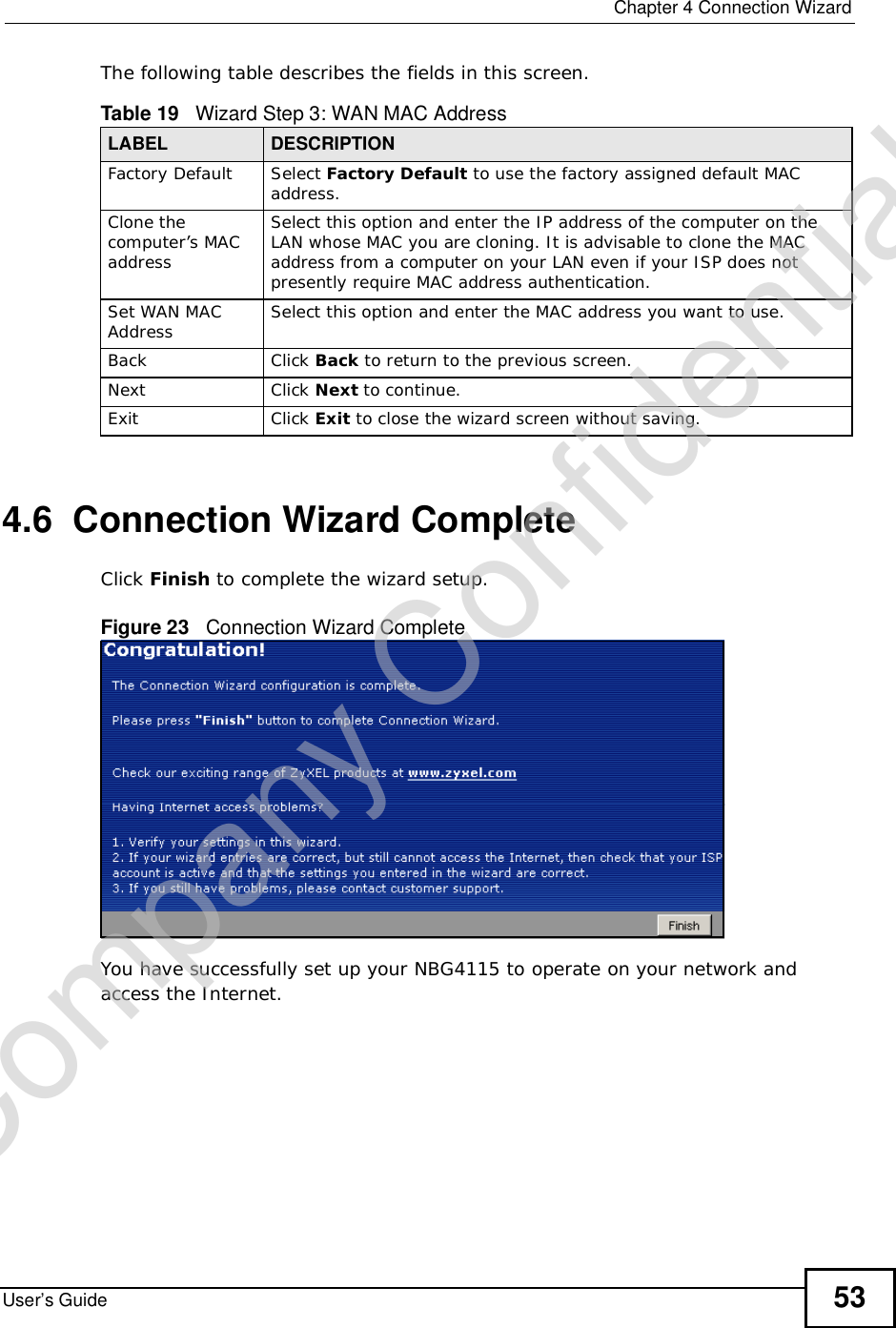
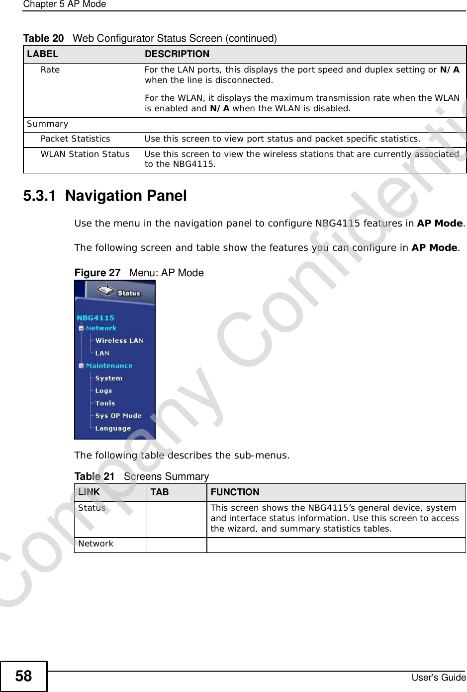
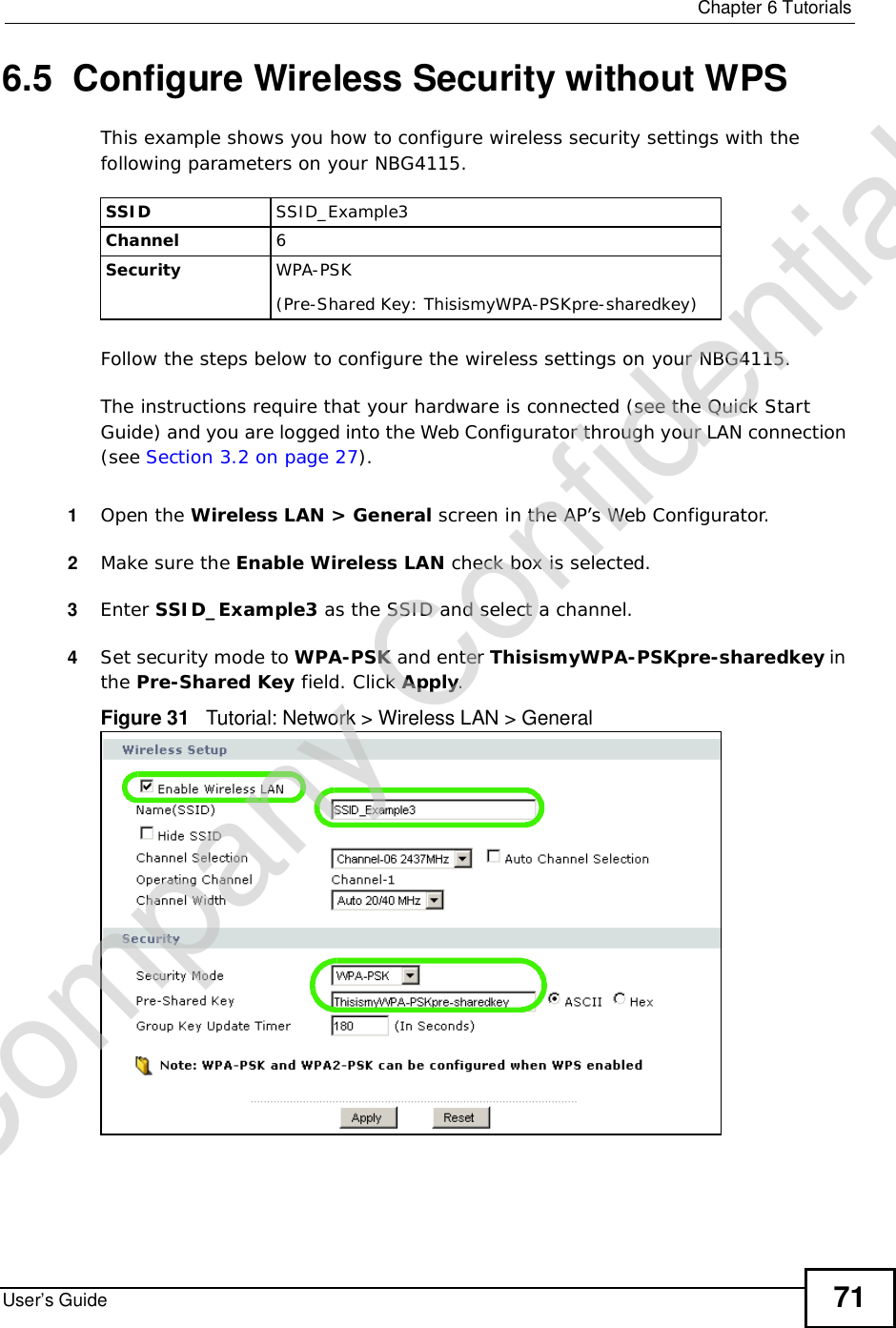
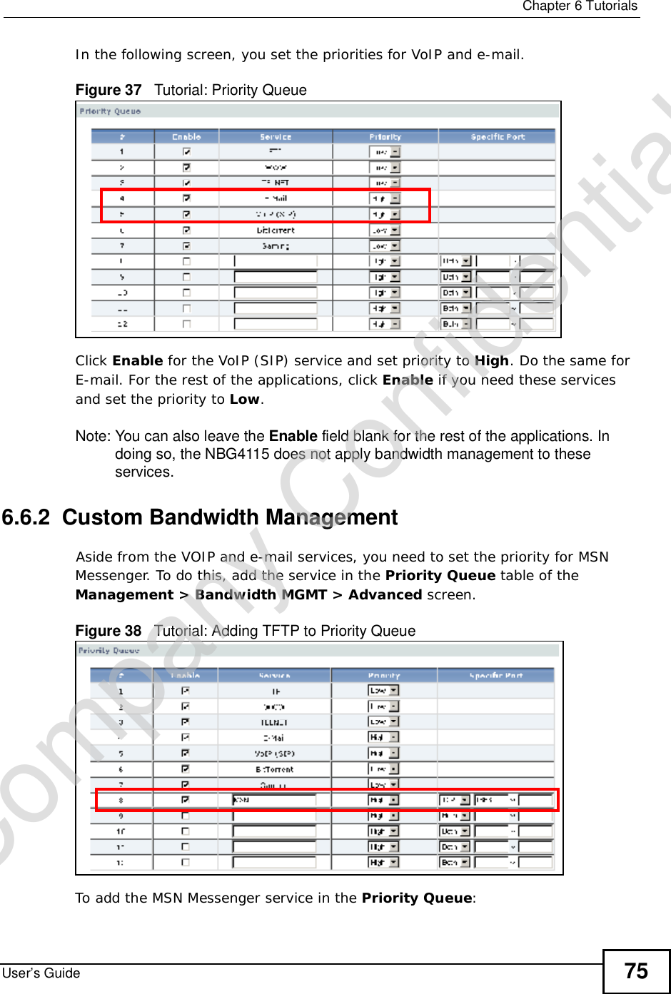
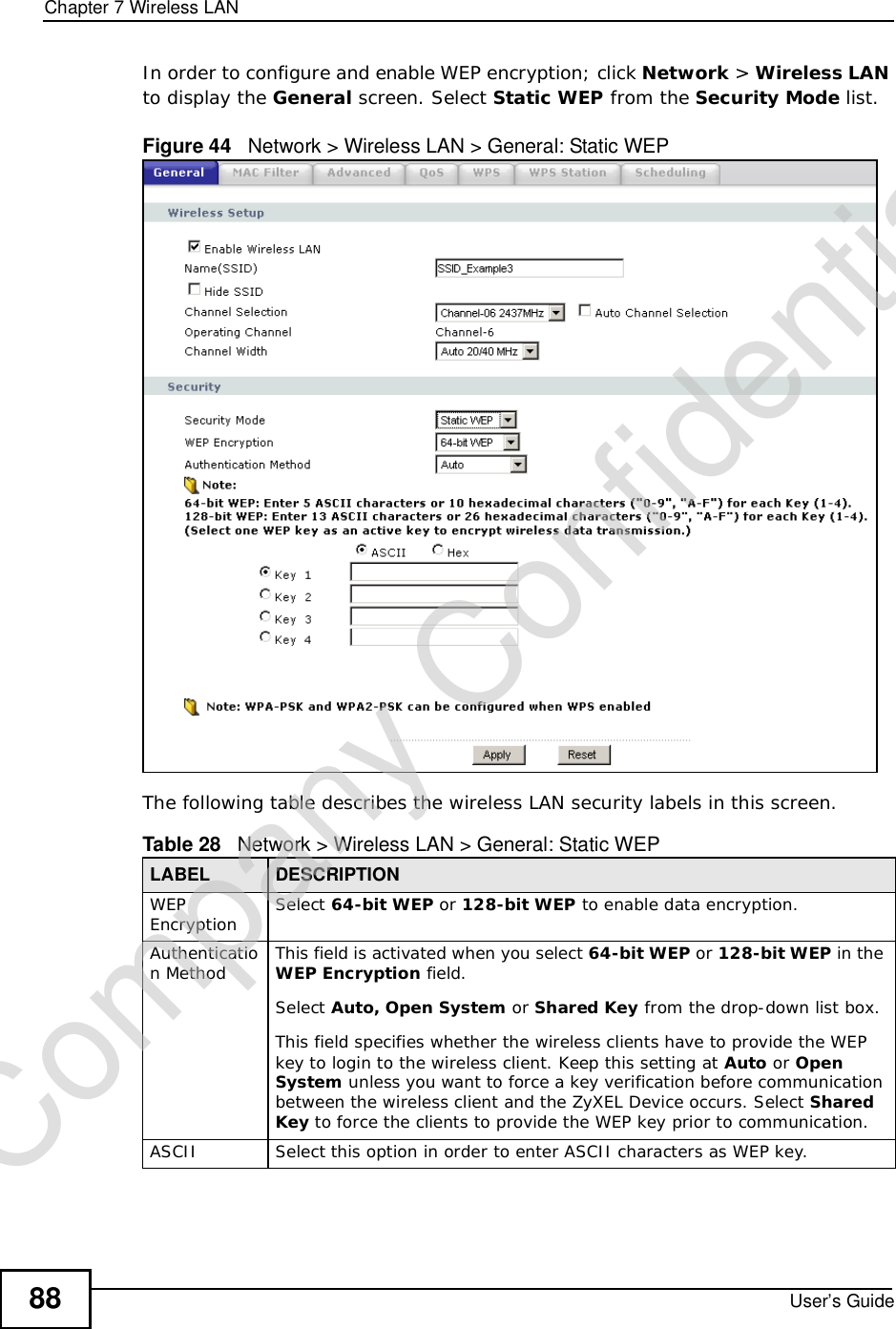
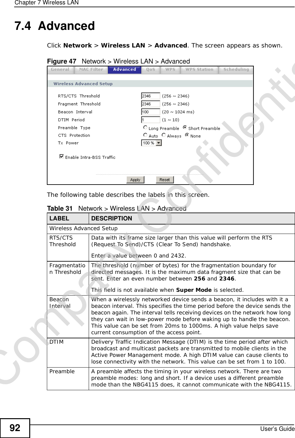
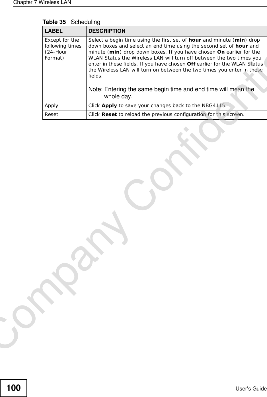
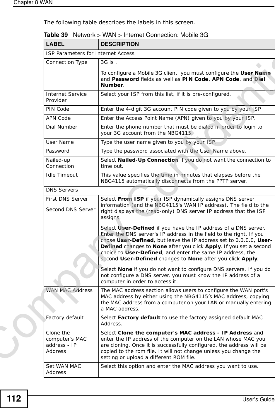
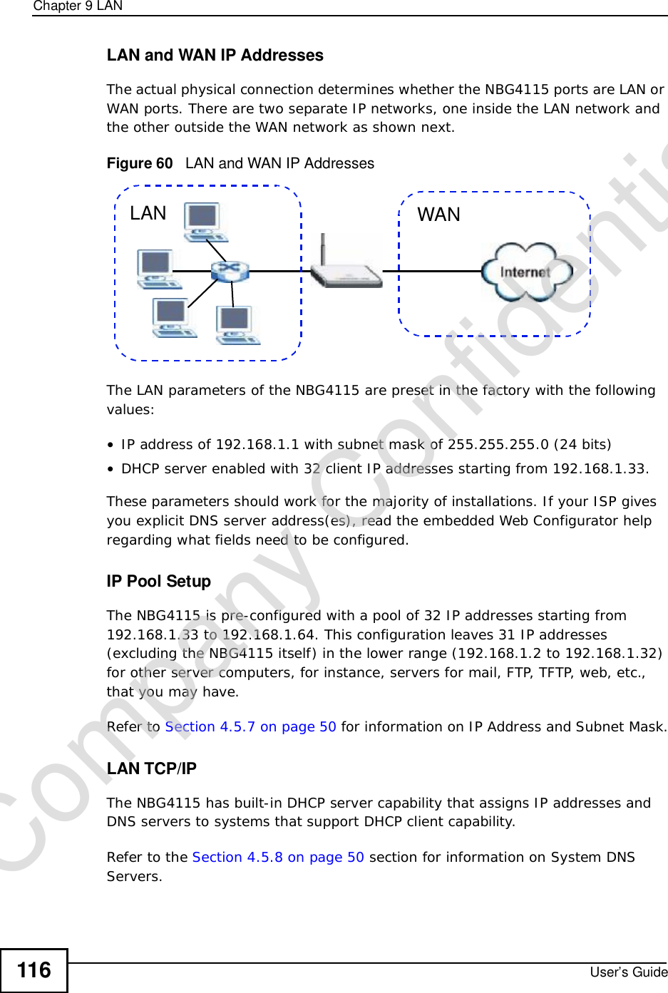
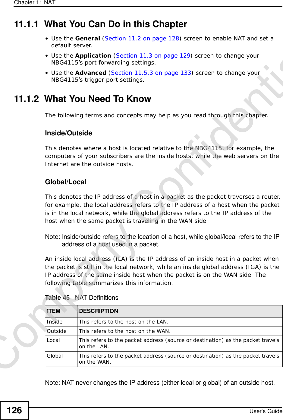
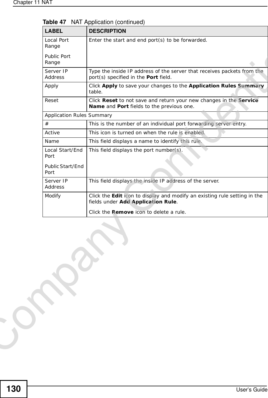
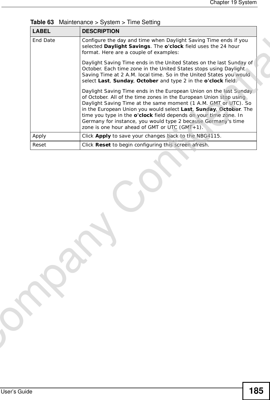
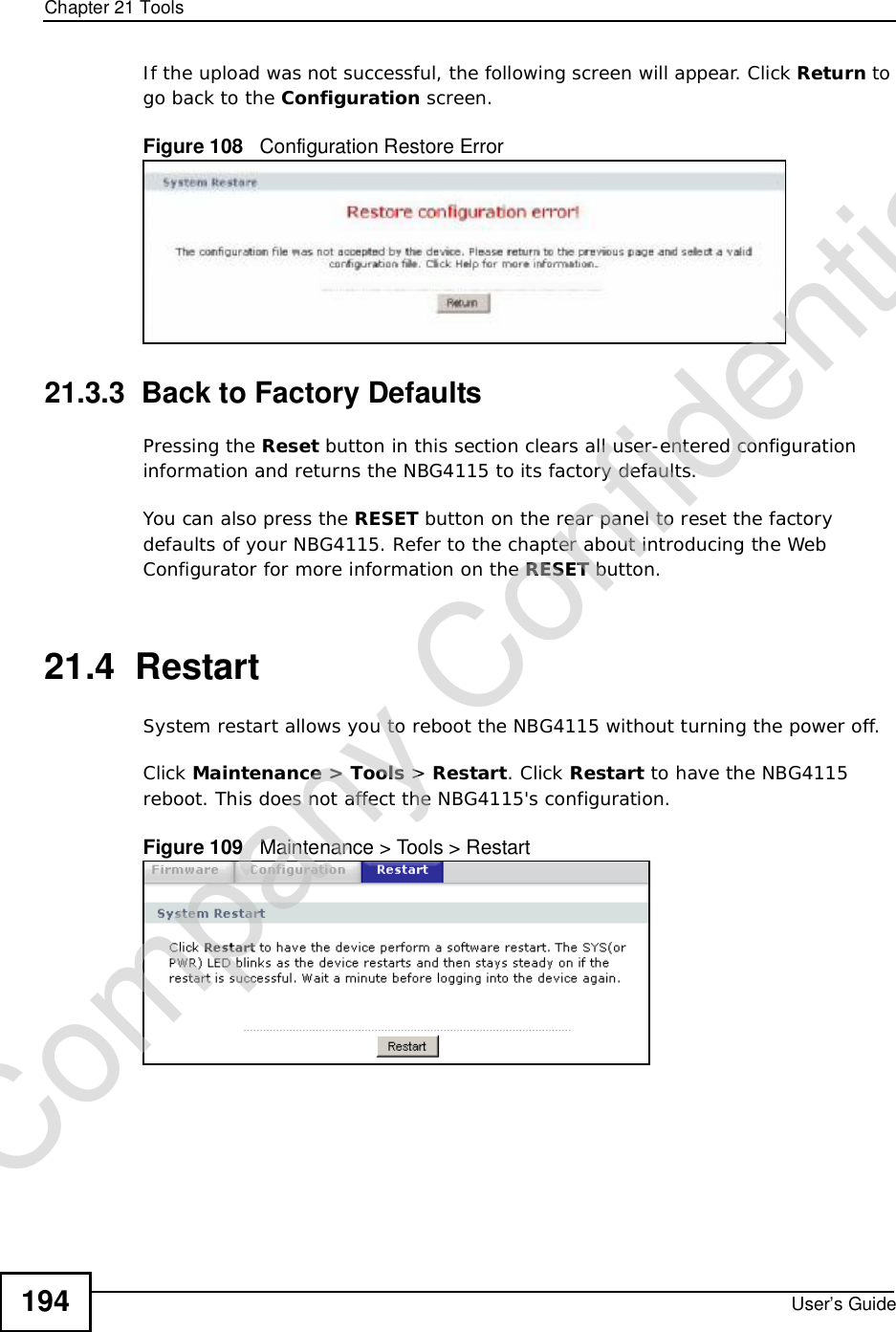
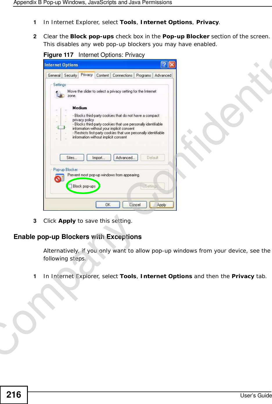
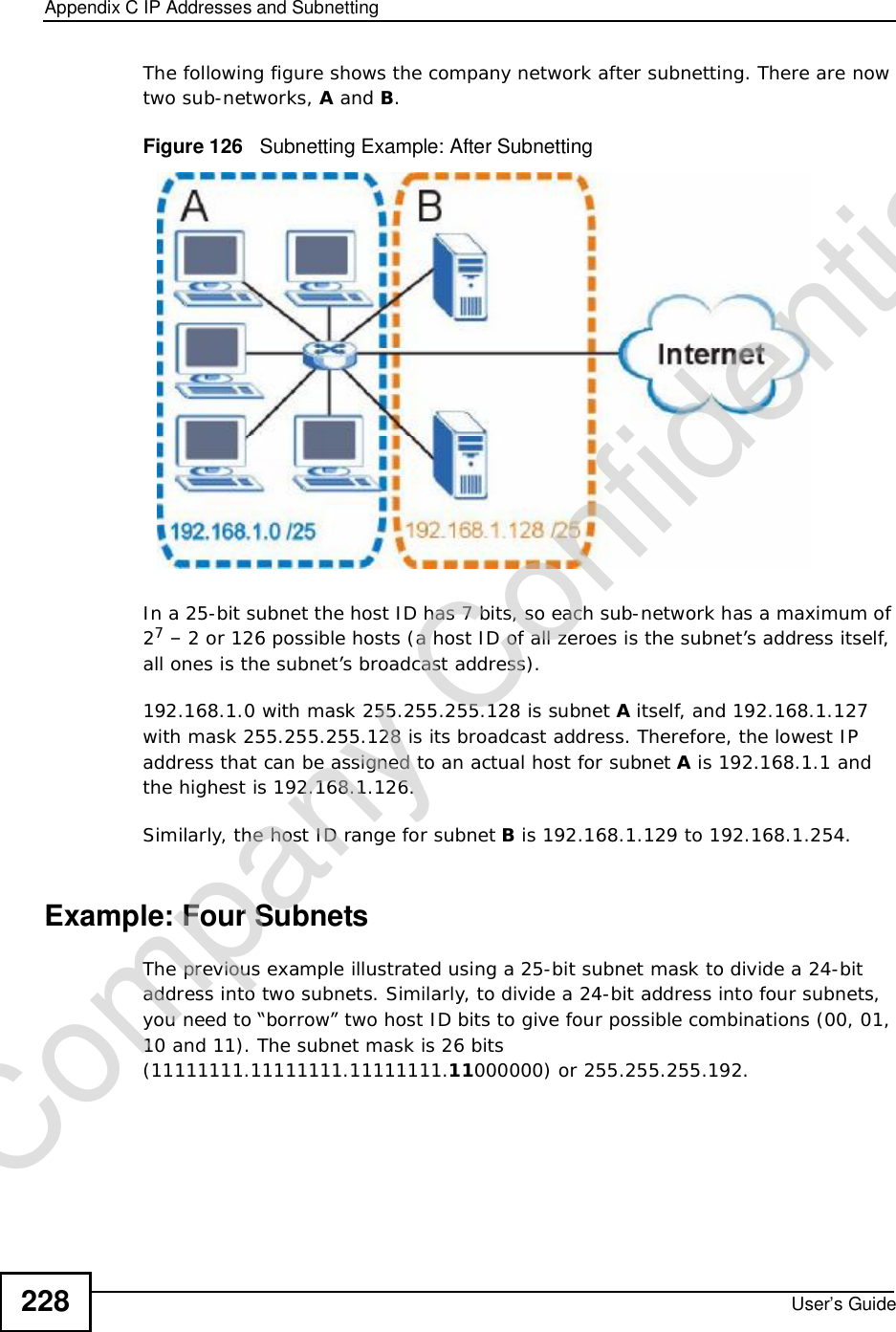
![Document ConventionsUser’s Guide6Document ConventionsWarnings and NotesThese are how warnings and notes are shown in this User’s Guide. Warnings tell you about things that could harm you or your device.Note: Notes tell you other important information (for example, other things you may need to configure or helpful tips) or recommendations.Syntax Conventions•The NBG4115 may be referred to as the “NBG4115”, the “device”, the “product” or the “system” in this User’s Guide.•Product labels, screen names, field labels and field choices are all in bold font.•A key stroke is denoted by square brackets and uppercase text, for example, [ENTER] means the “enter” or “return” key on your keyboard.•“Enter” means for you to type one or more characters and then press the [ENTER] key. “Select” or “choose” means for you to use one of the predefined choices.•A right angle bracket ( > ) within a screen name denotes a mouse click. For example, Maintenance > Log > Log Setting means you first click Maintenance in the navigation panel, then the Log sub menu and finally the Log Setting tab to get to that screen.•Units of measurement may denote the “metric” value or the “scientific” value. For example, “k” for kilo may denote “1000” or “1024”, “M” for mega may denote “1000000” or “1048576” and so on.•“e.g.,” is a shorthand for “for instance”, and “i.e.,” means “that is” or “in other words”.Company Confidential](https://usermanual.wiki/ZyXEL-Communications/NBG417N.User-Manual/User-Guide-1164748-Page-5.png)
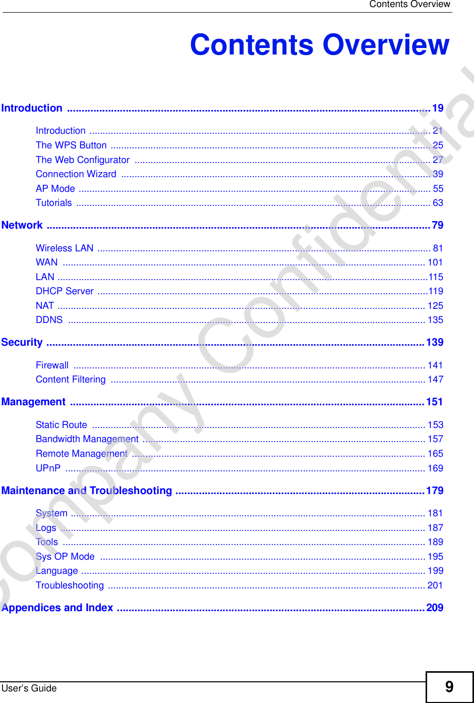


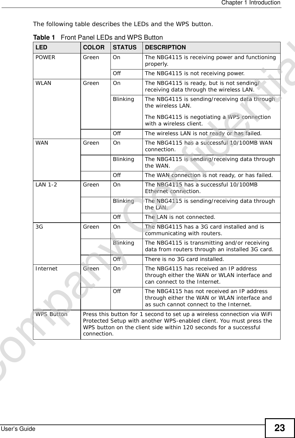


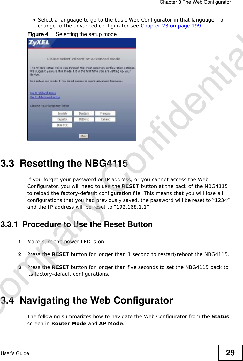
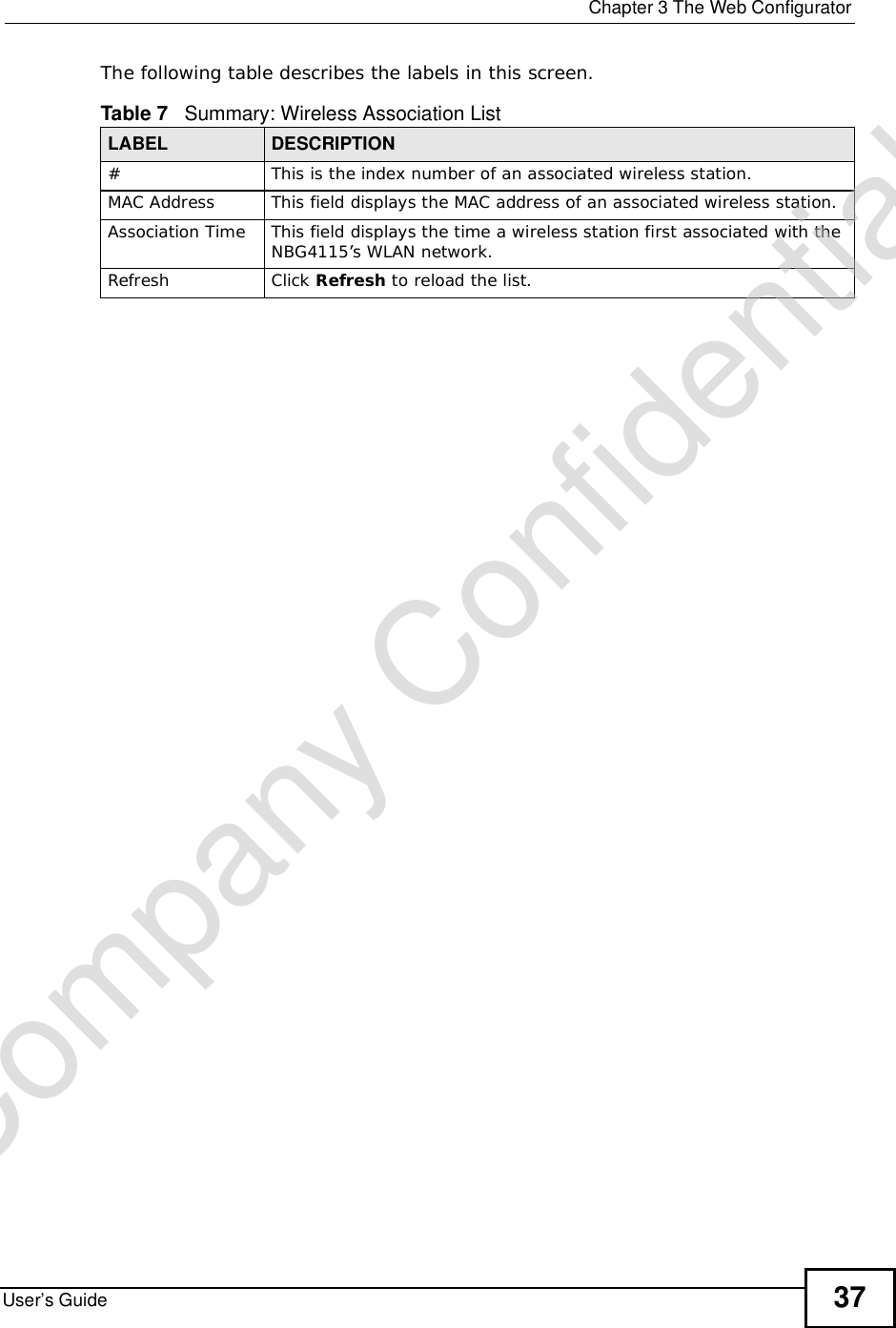

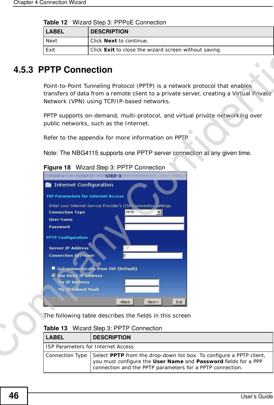
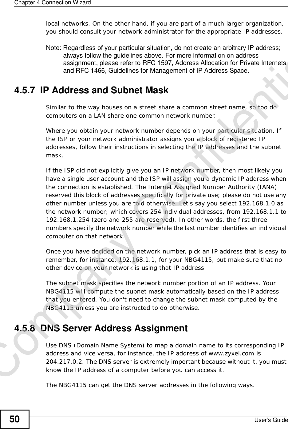

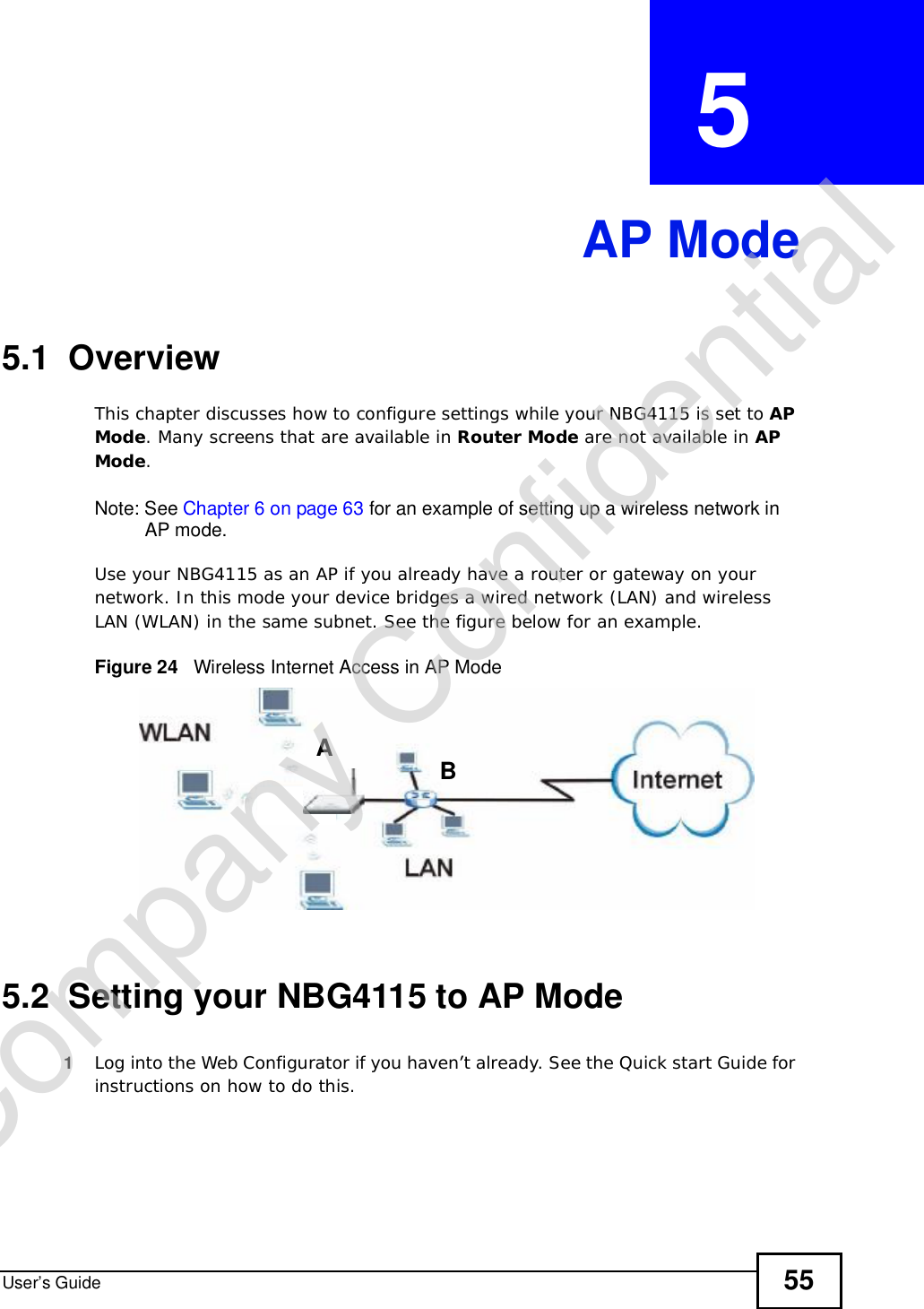
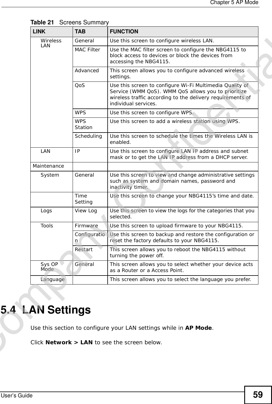

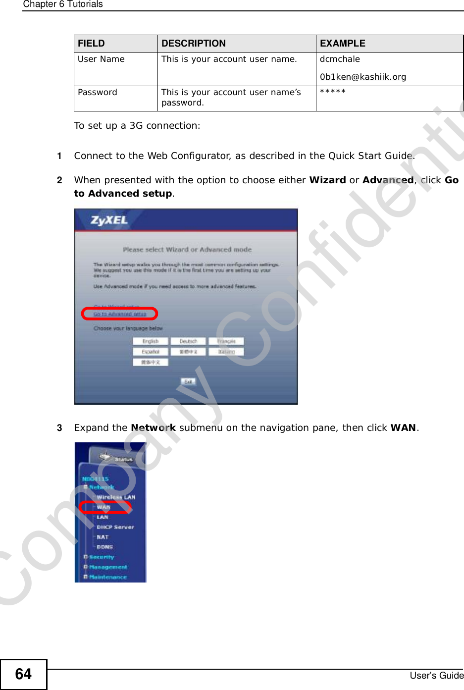
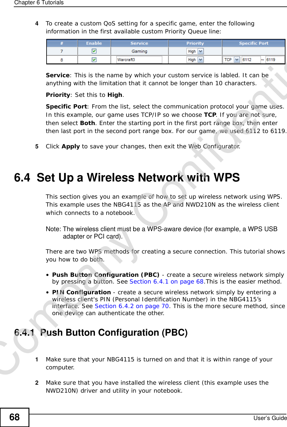
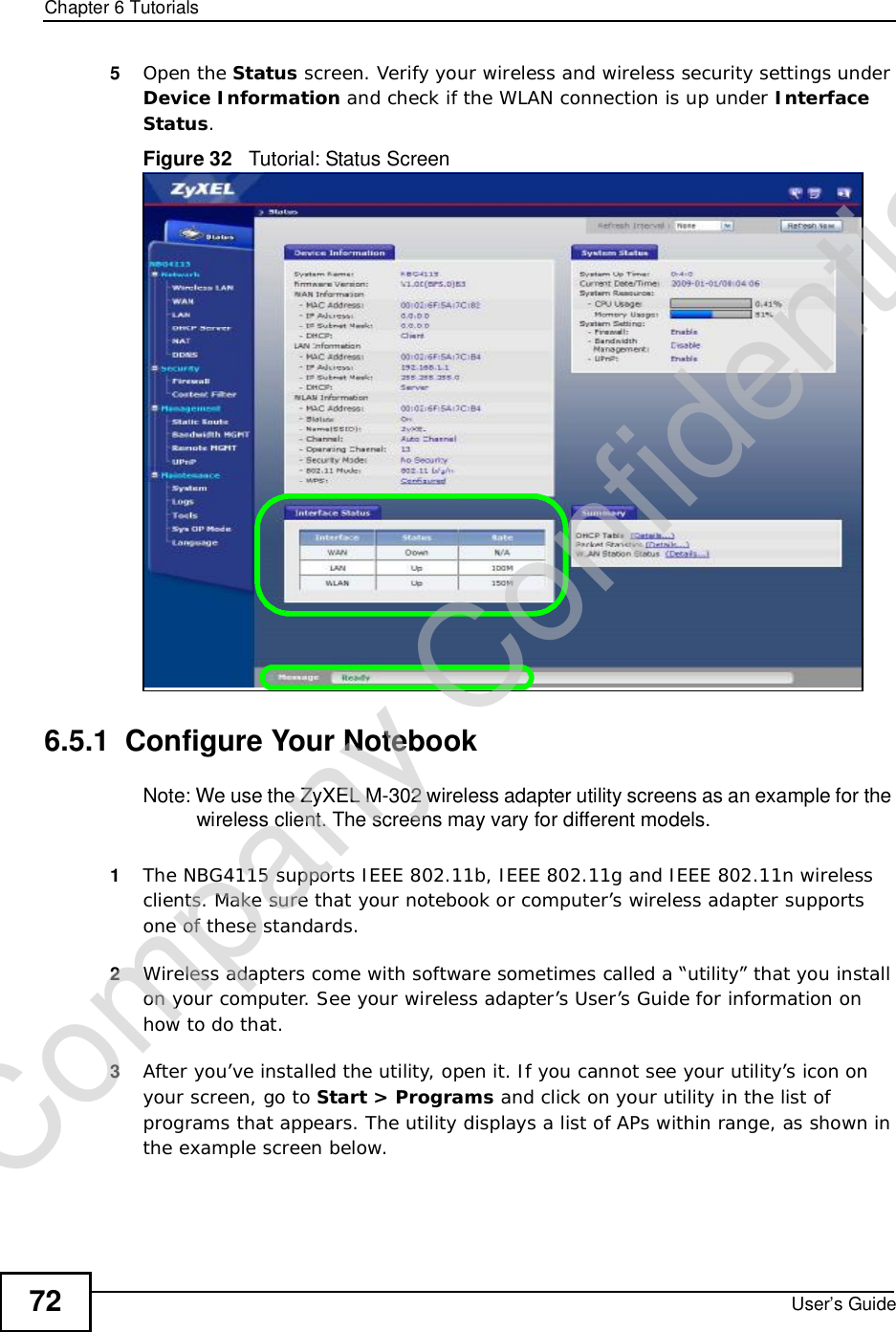
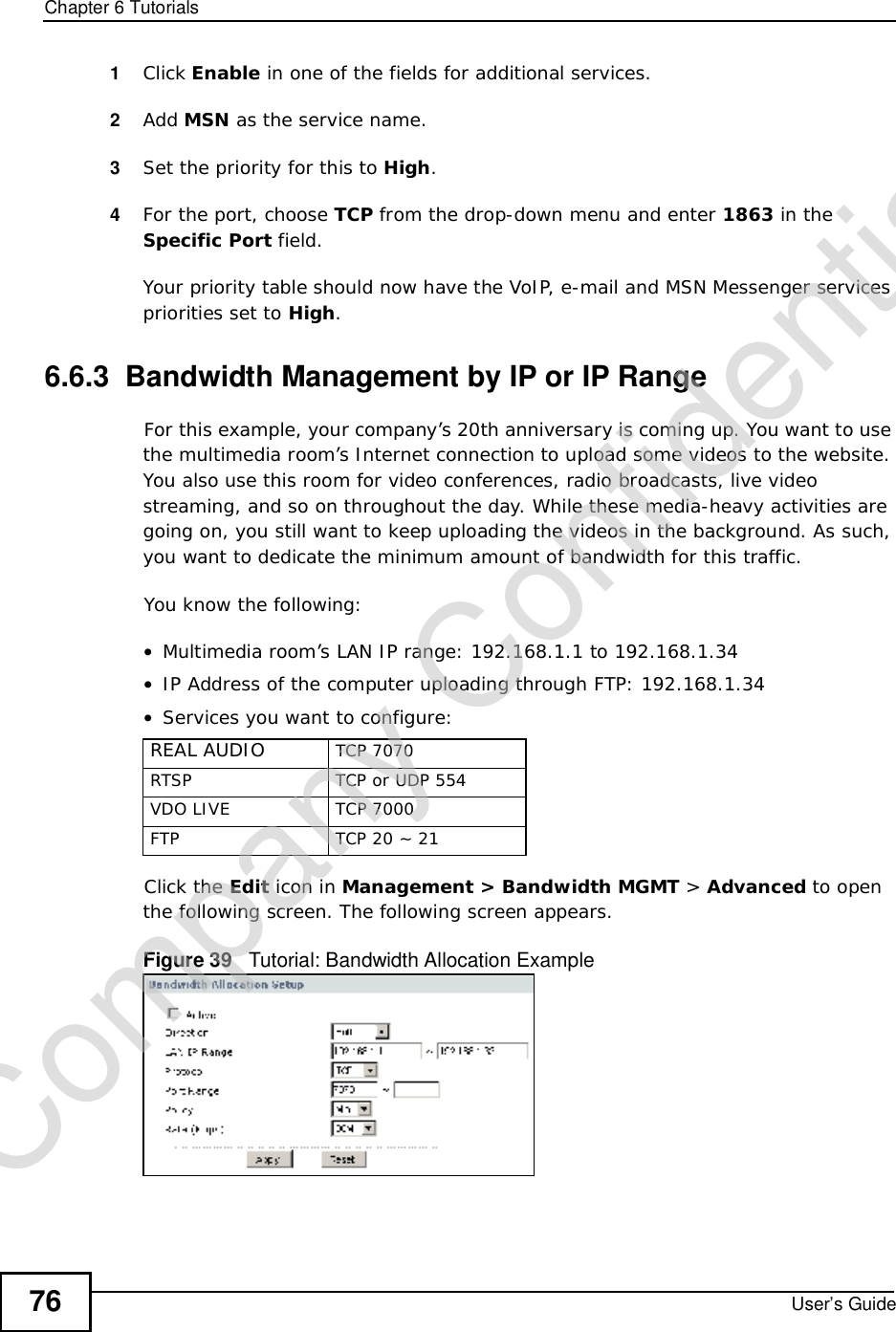

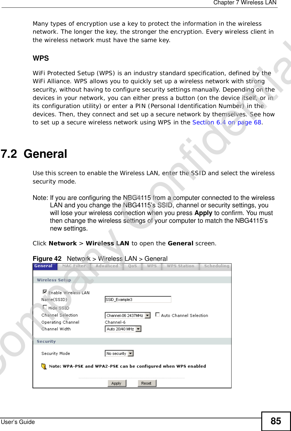
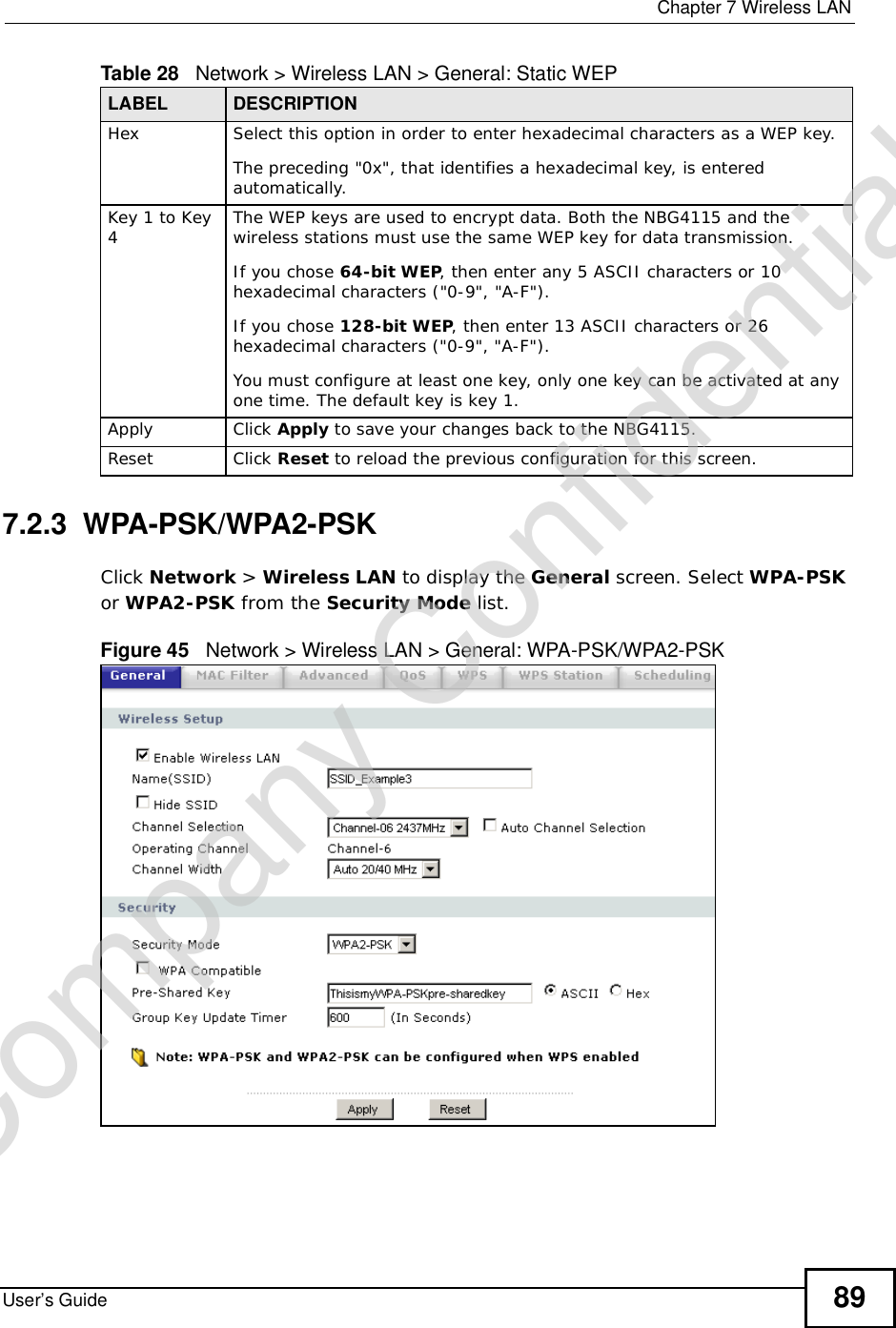
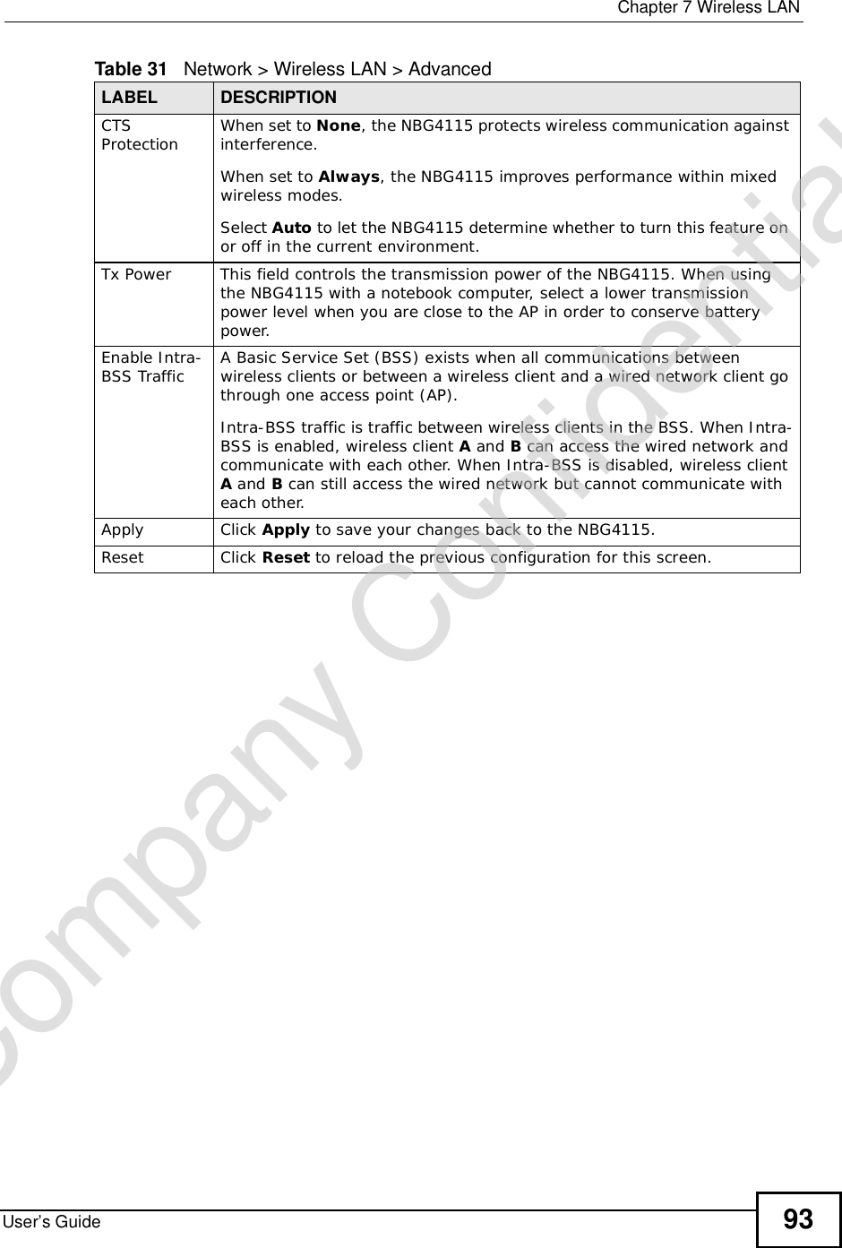
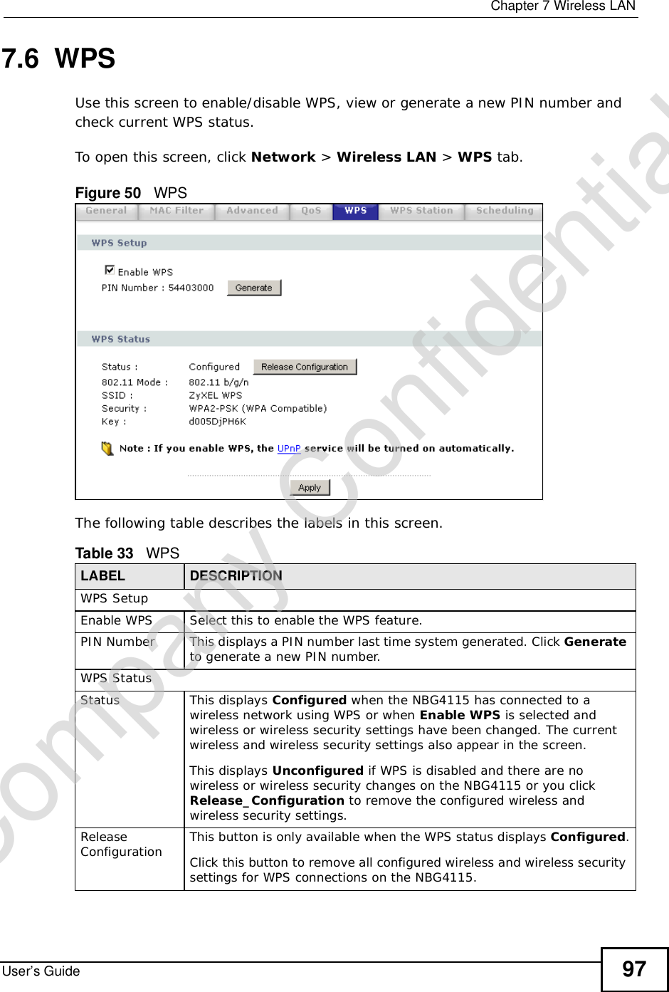
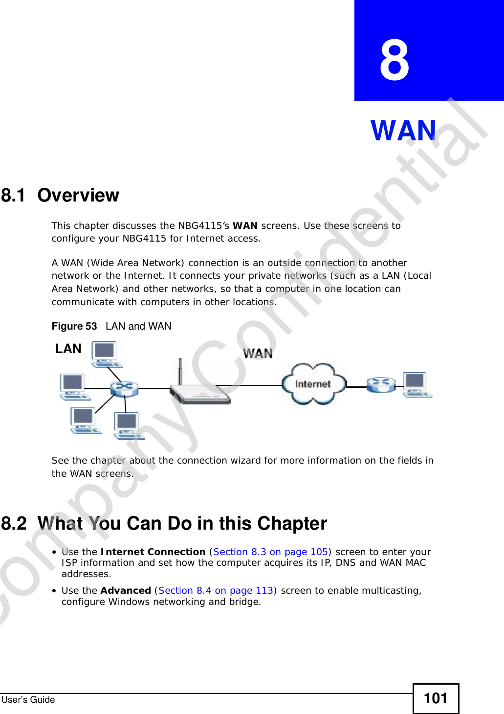
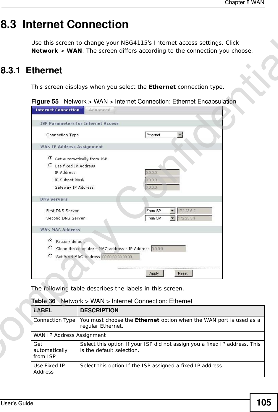
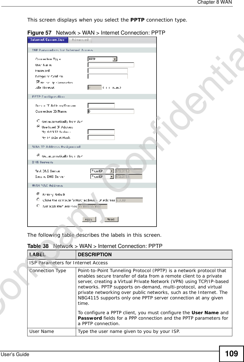
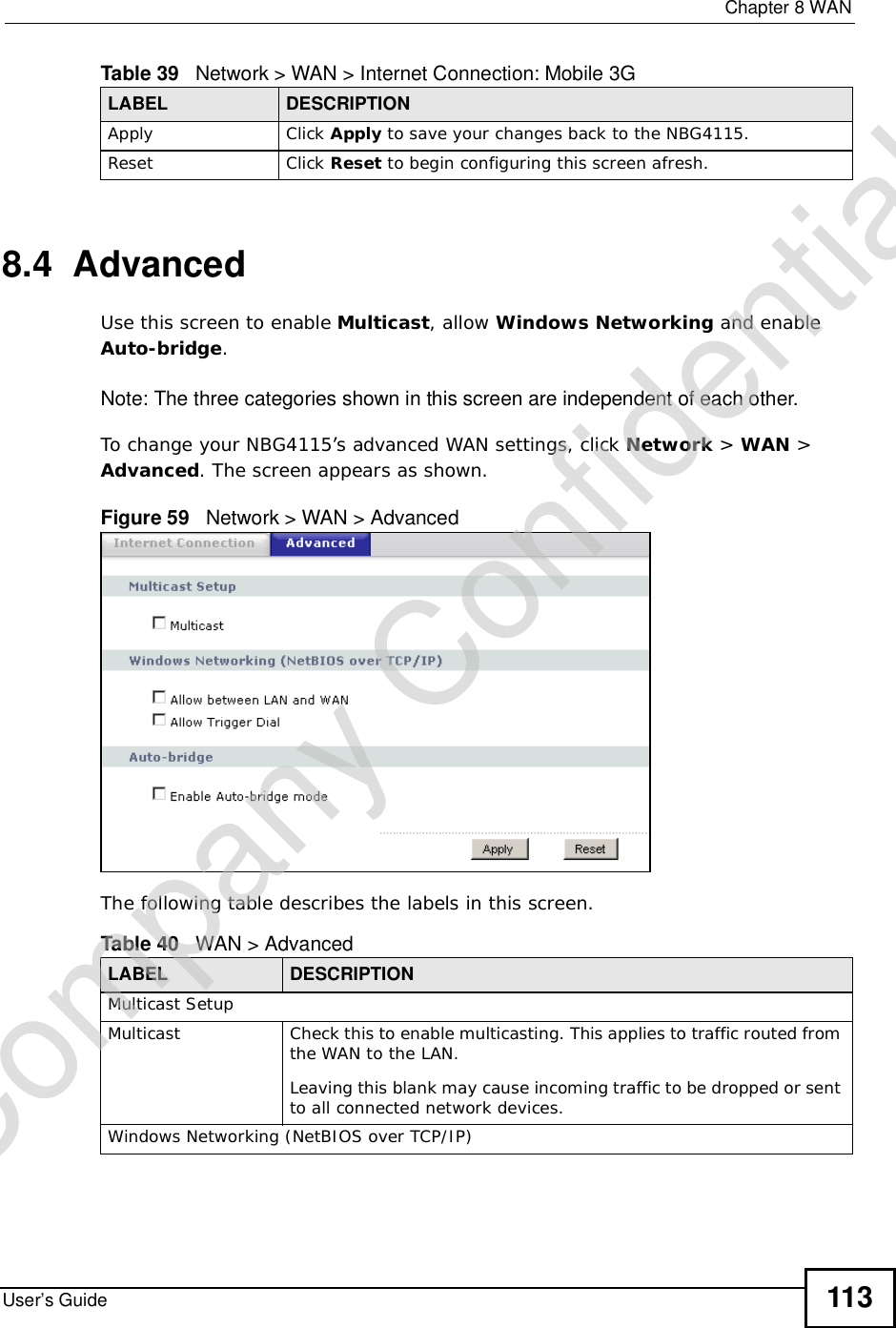
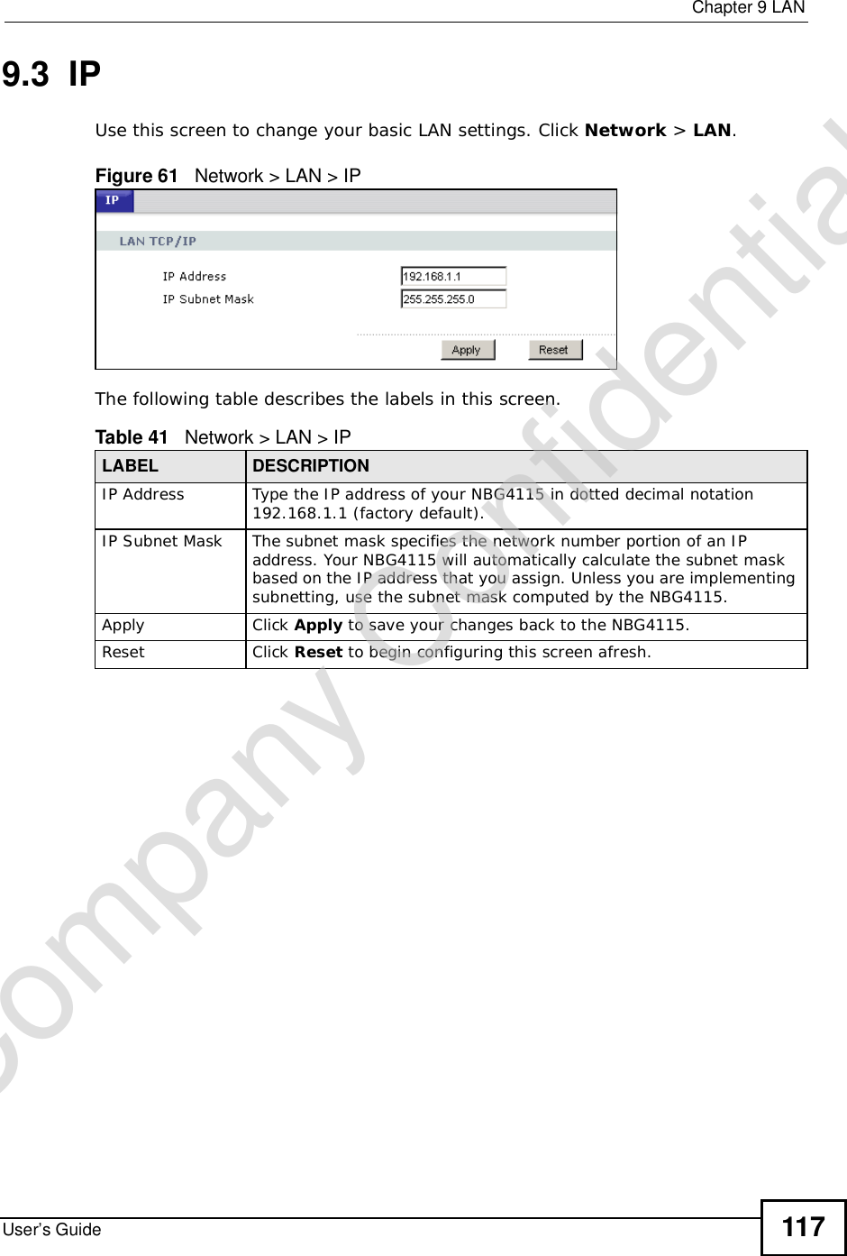


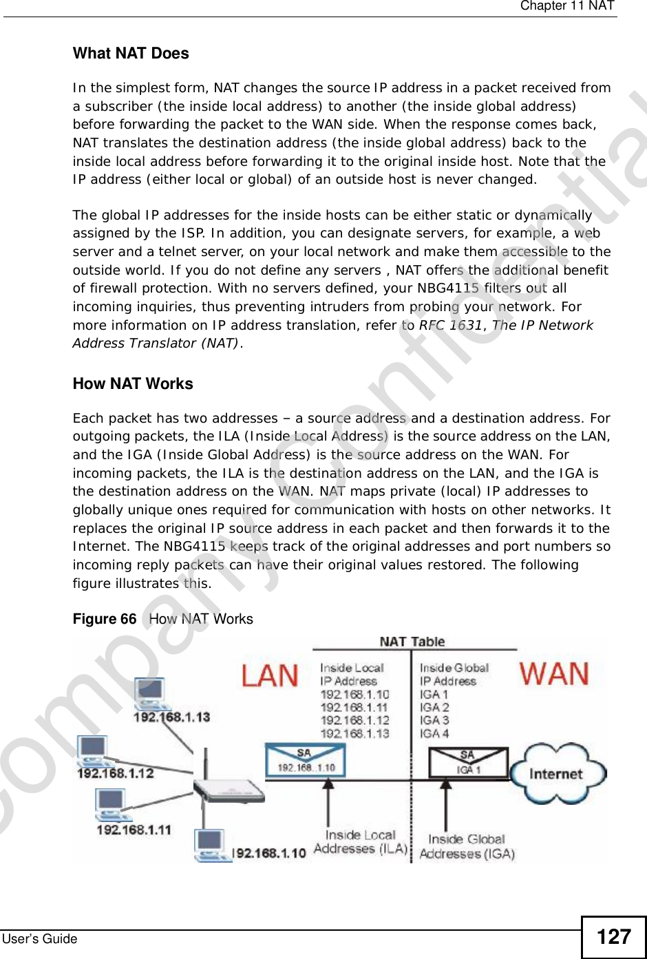
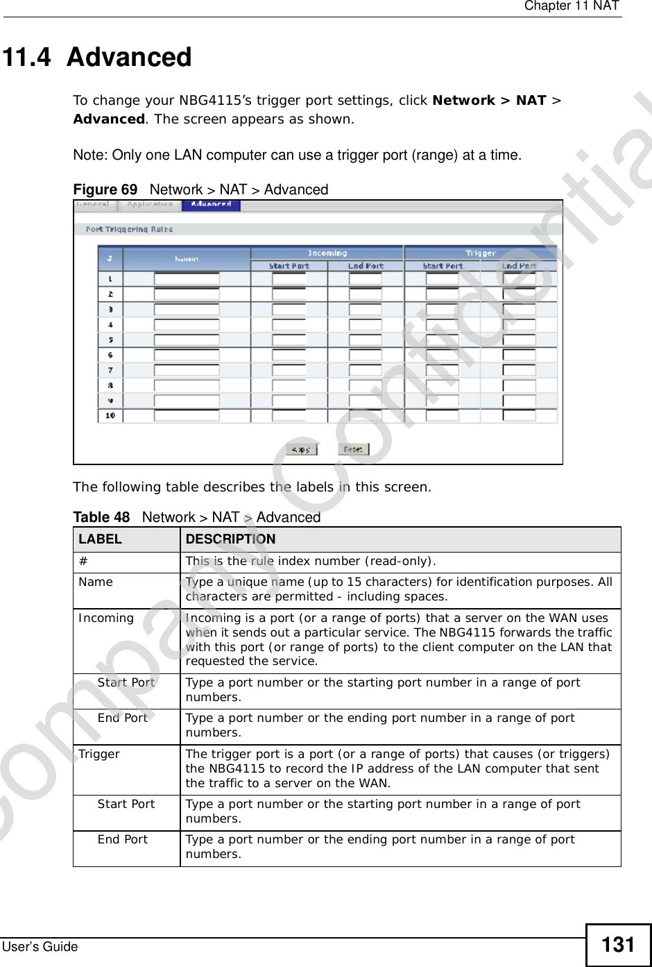
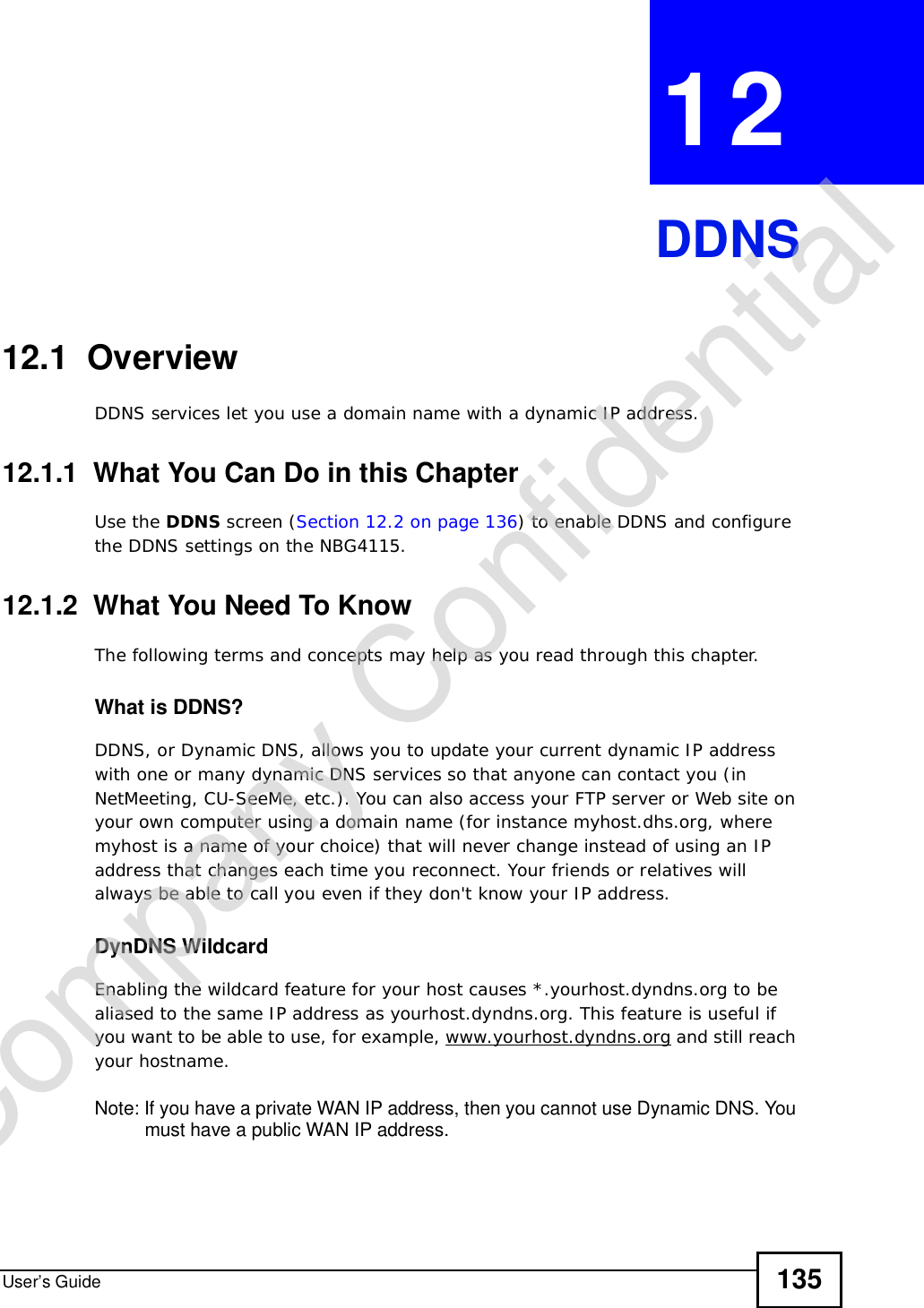


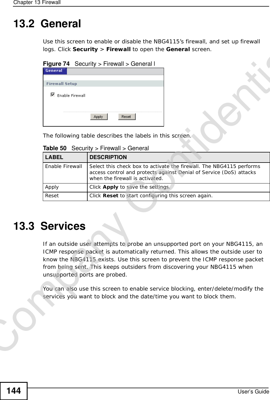
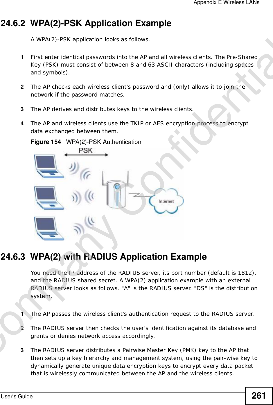
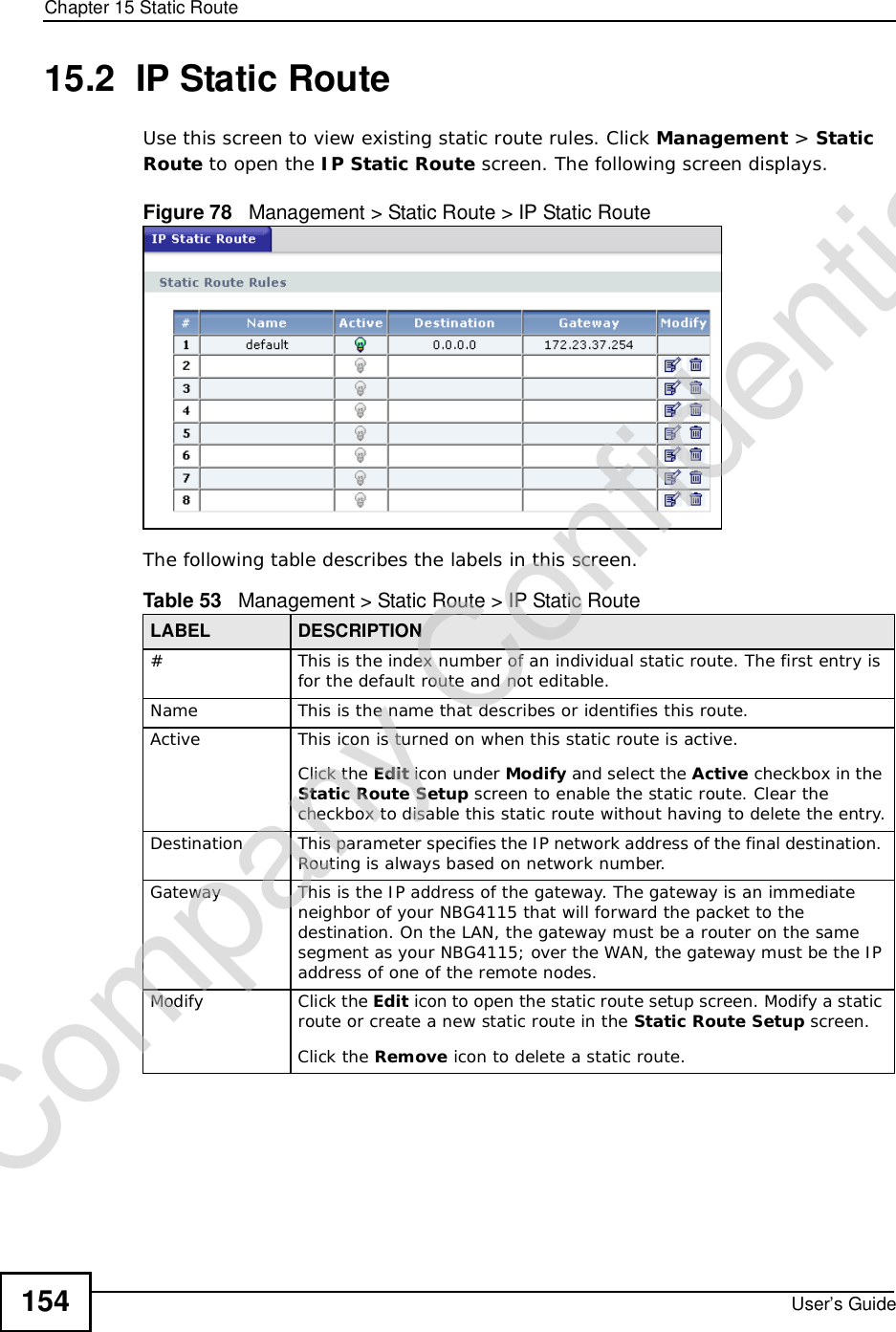
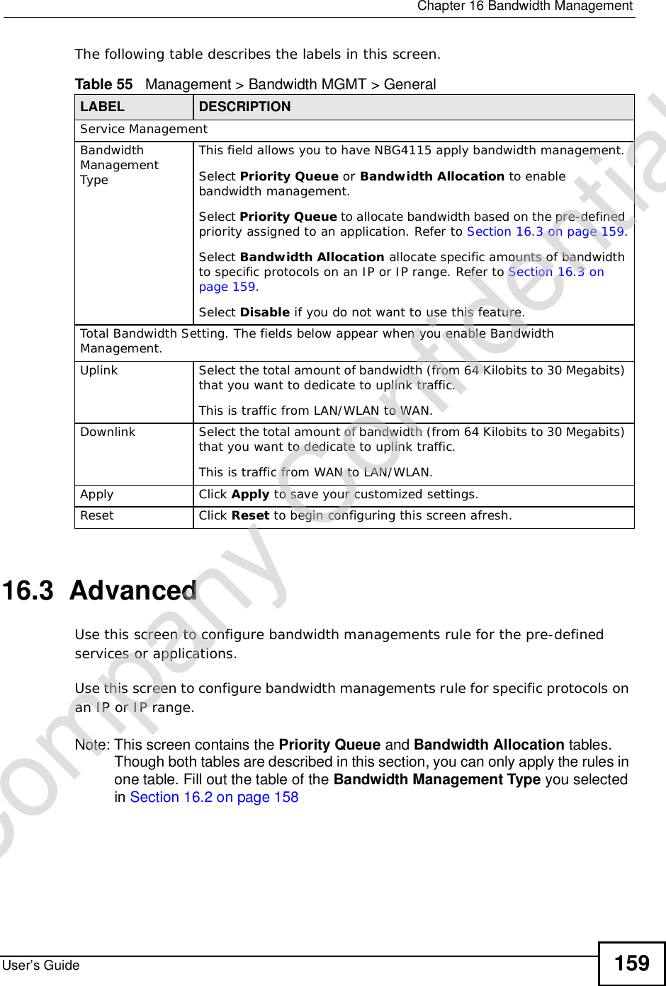
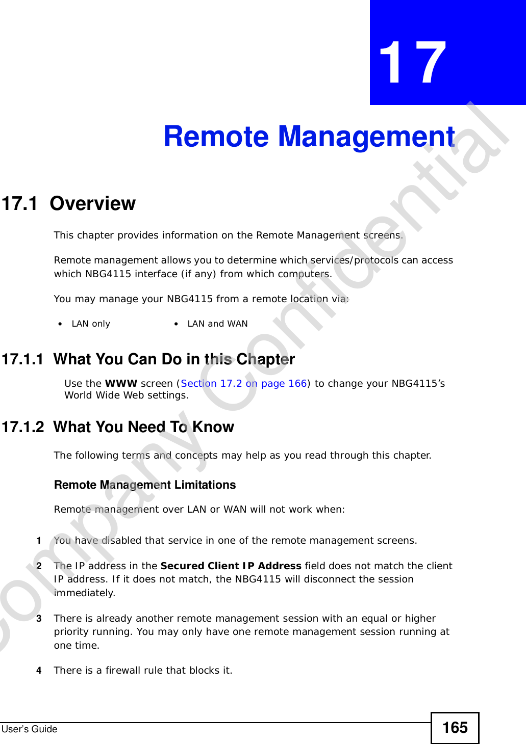
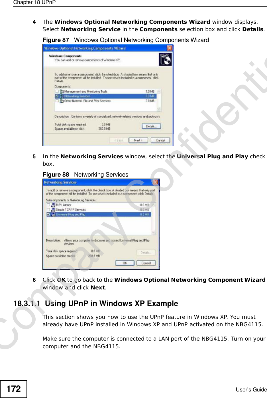
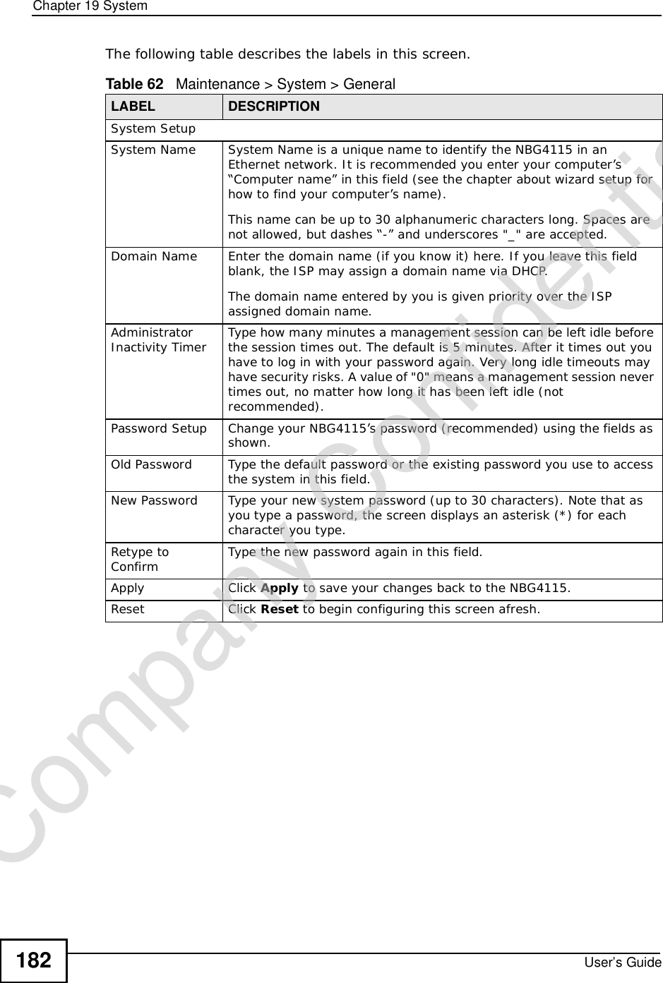
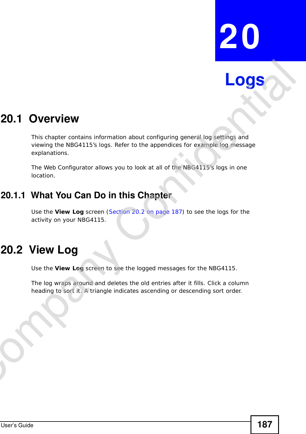
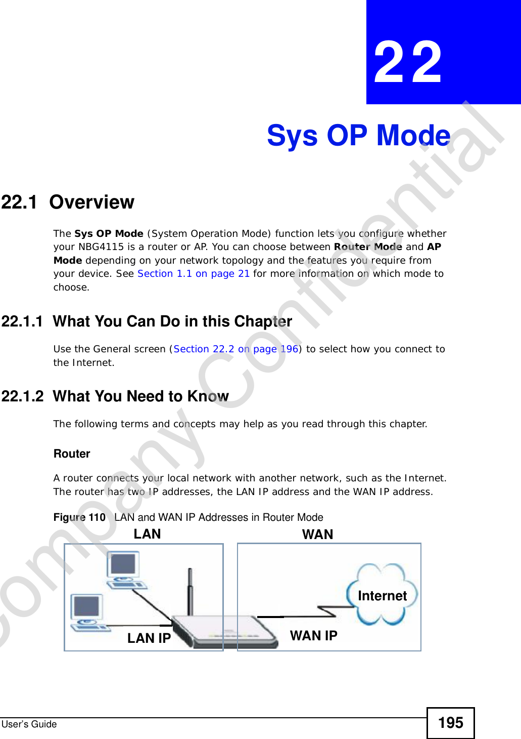
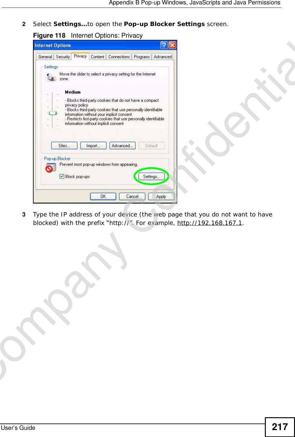
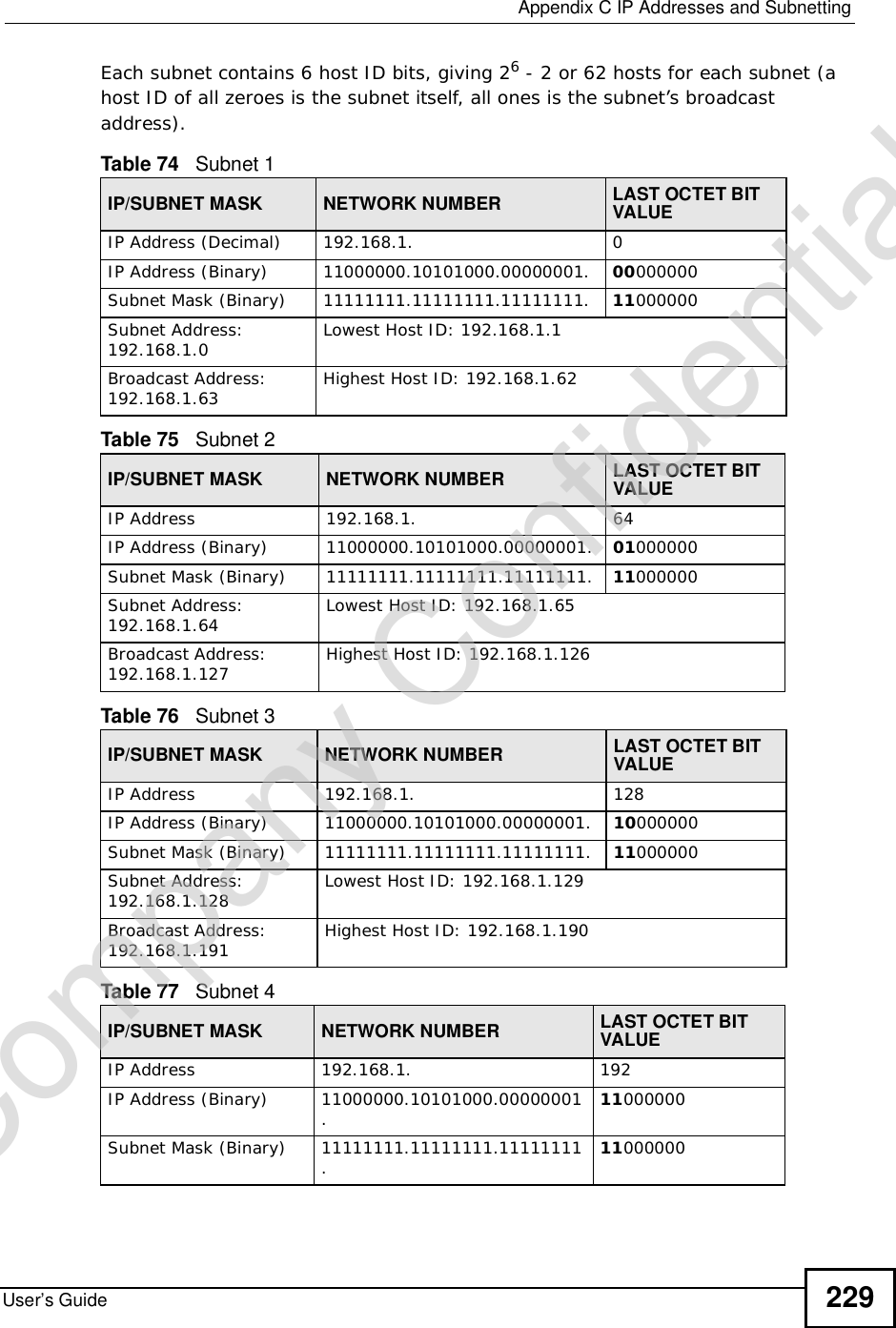
![Chapter 13FirewallUser’s Guide 145Click Security > Firewall > Services. The screen appears as shown next. Figure 75 Security > Firewall > Services lThe following table describes the labels in this screen.Table 51 Security > Firewall > ServicesLABEL DESCRIPTIONICMP Internet Control Message Protocol is a message control and error-reporting protocol between a host server and a gateway to the Internet. ICMP uses Internet Protocol (IP) datagrams, but the messages are processed by the TCP/IP software and directly apparent to the application user. Respond to Ping on The NBG4115 will not respond to any incoming Ping requests when Disable is selected. Select LAN to reply to incoming LAN Ping requests.Select WAN to reply to incoming WAN Ping requests. Otherwise select LAN & WAN to reply to all incoming LAN and WAN Ping requests. Do not respond to requests for unauthorized servicesSelect this option to prevent hackers from finding the NBG4115 by probing for unused ports. If you select this option, the NBG4115 will not respond to port request(s) for unused ports, thus leaving the unused ports and the NBG4115 unseen. By default this option is not selected and the NBG4115 will reply with an ICMP Port Unreachable packet for a port probe on its unused UDP ports, and a TCP Reset packet for a port probe on its unused TCP ports. Note that the probing packets must first traverse the NBG4115's firewall mechanism before reaching this anti-probing mechanism. Therefore if the firewall mechanism blocks a probing packet, the NBG4115 reacts based on the firewall policy, which by default, is to send a TCP reset packet for a blocked TCP packet. You can use the command "sys firewall tcprst rst [on|off]" to change this policy. When the firewall mechanism blocks a UDP packet, it drops the packet without sending a response packet.Apply Click Apply to save the settings. Reset Click Reset to start configuring this screen again. Company Confidential](https://usermanual.wiki/ZyXEL-Communications/NBG417N.User-Manual/User-Guide-1164748-Page-144.png)

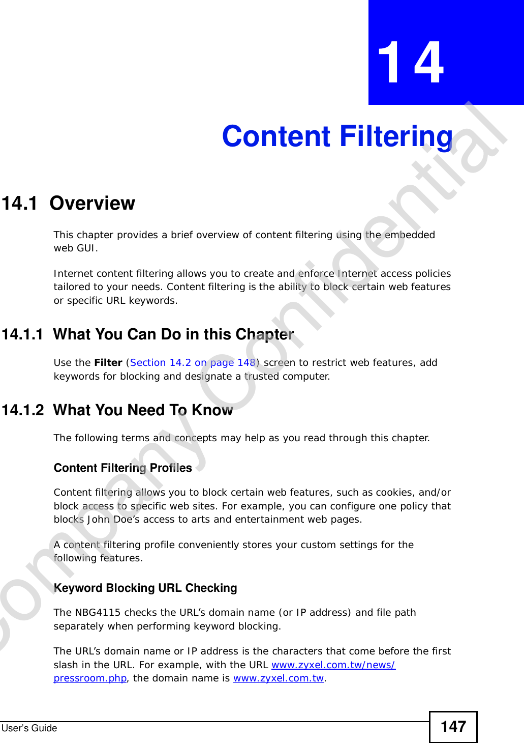
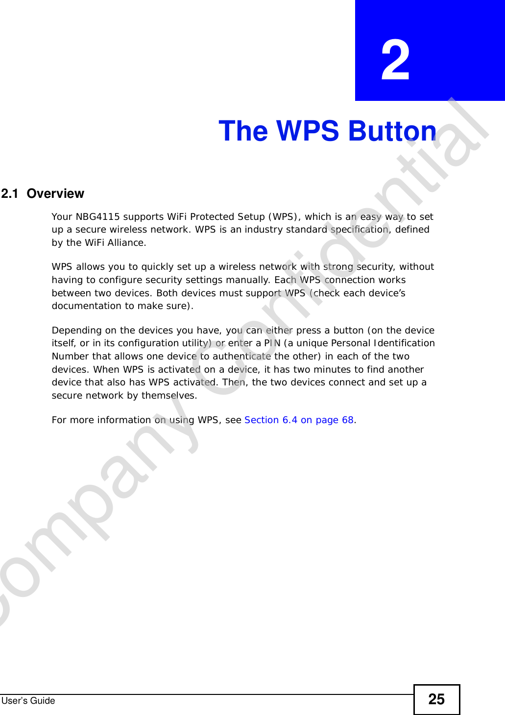
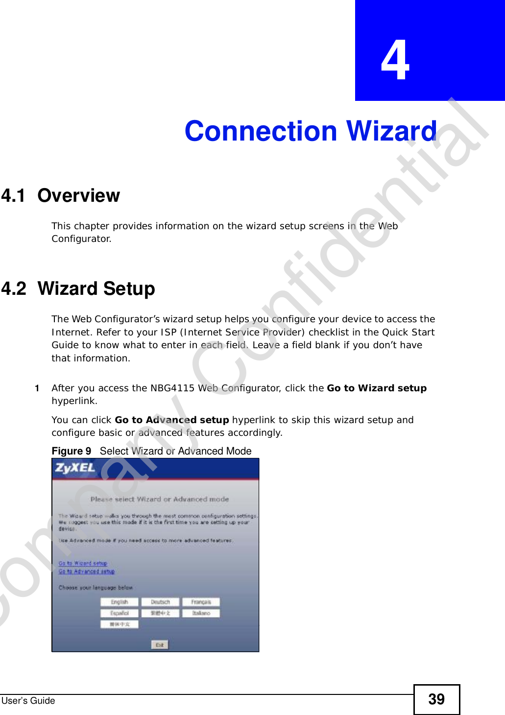
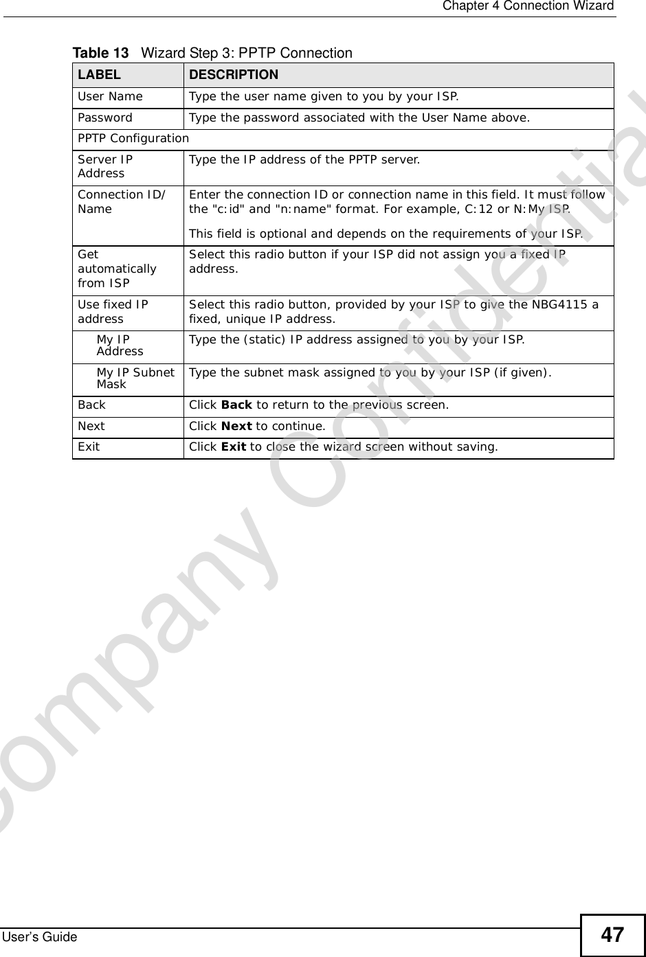
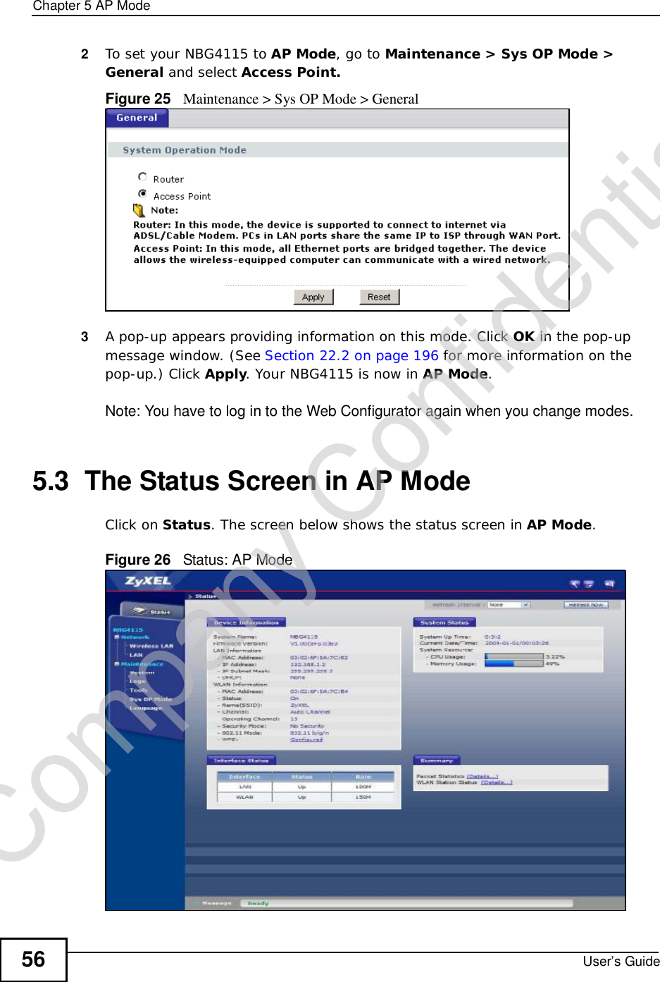
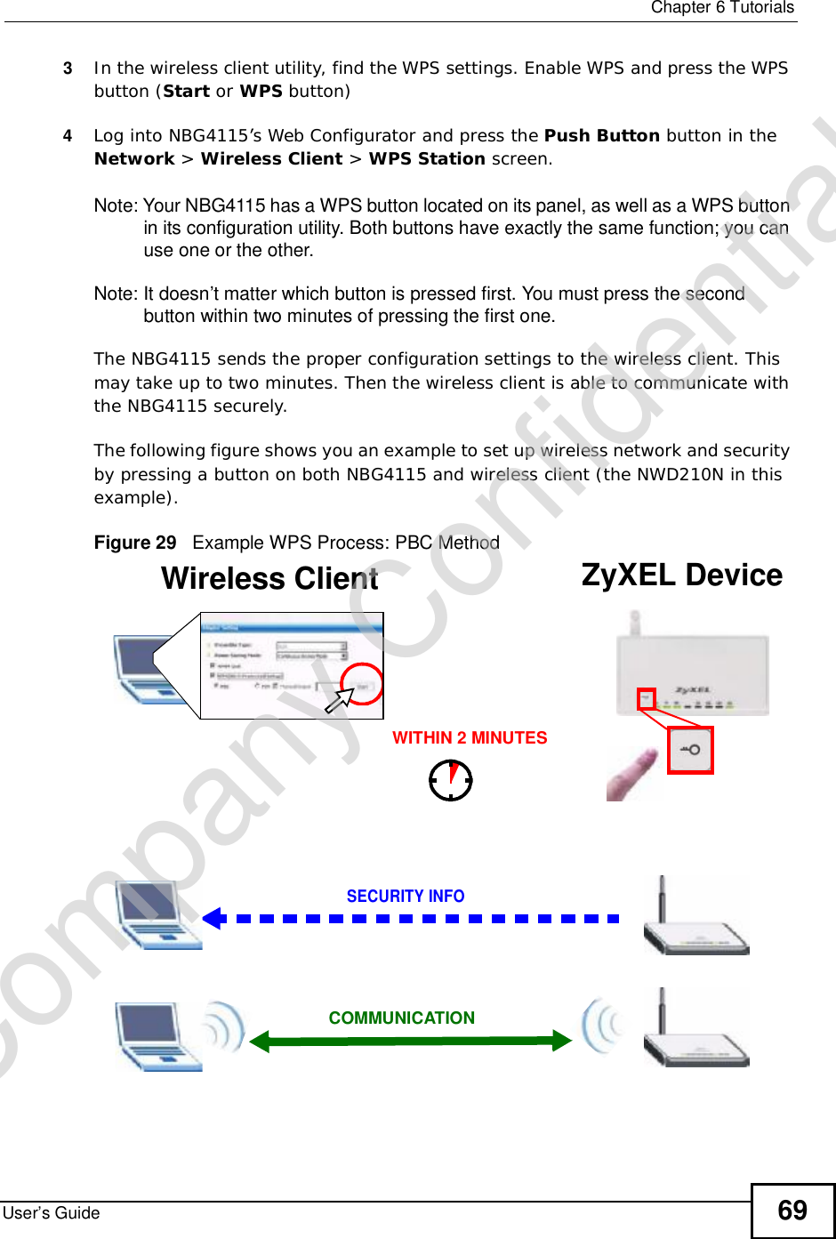
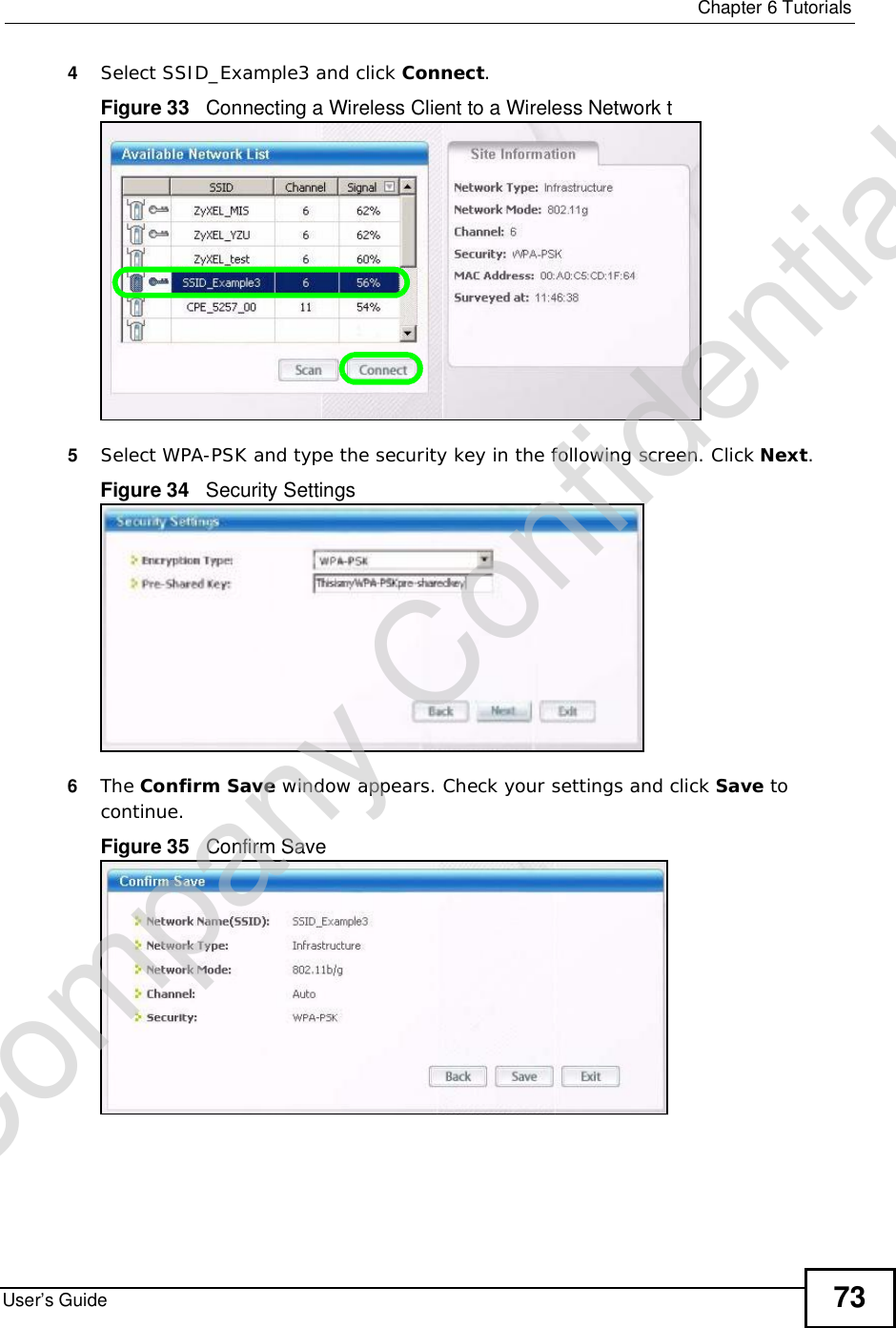
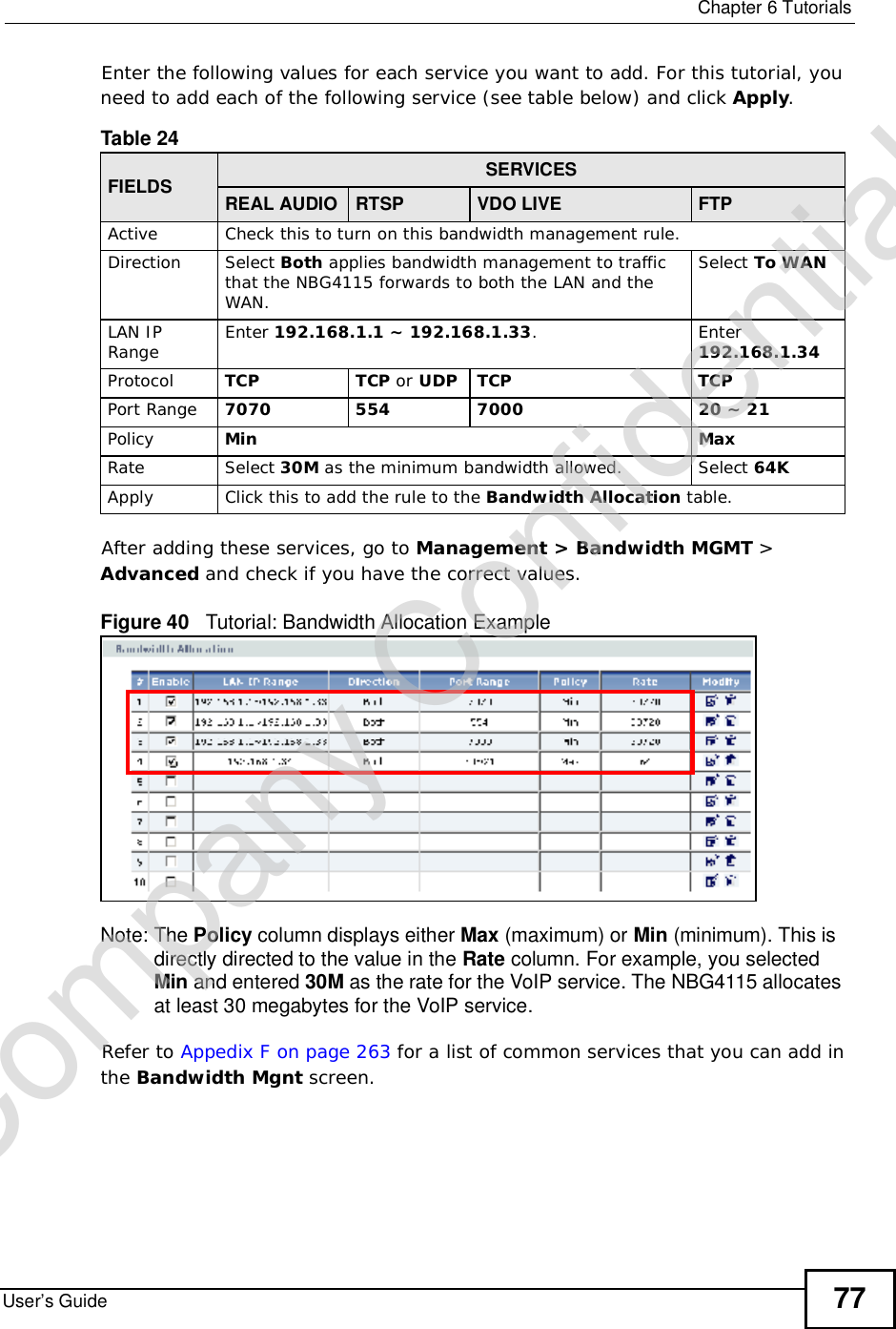
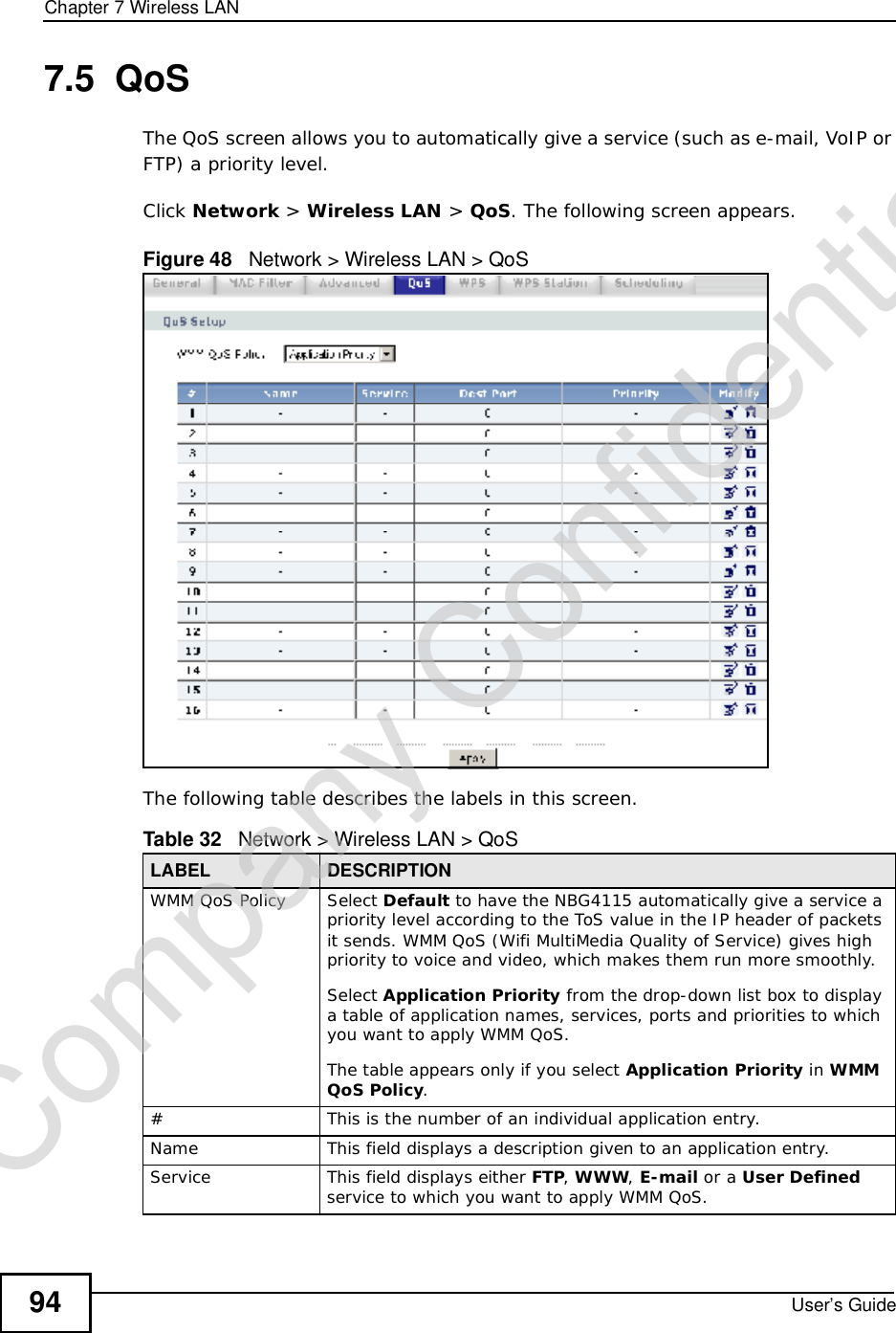
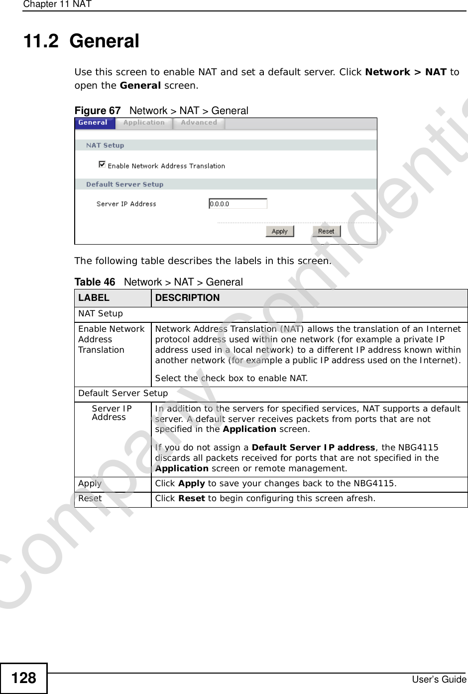
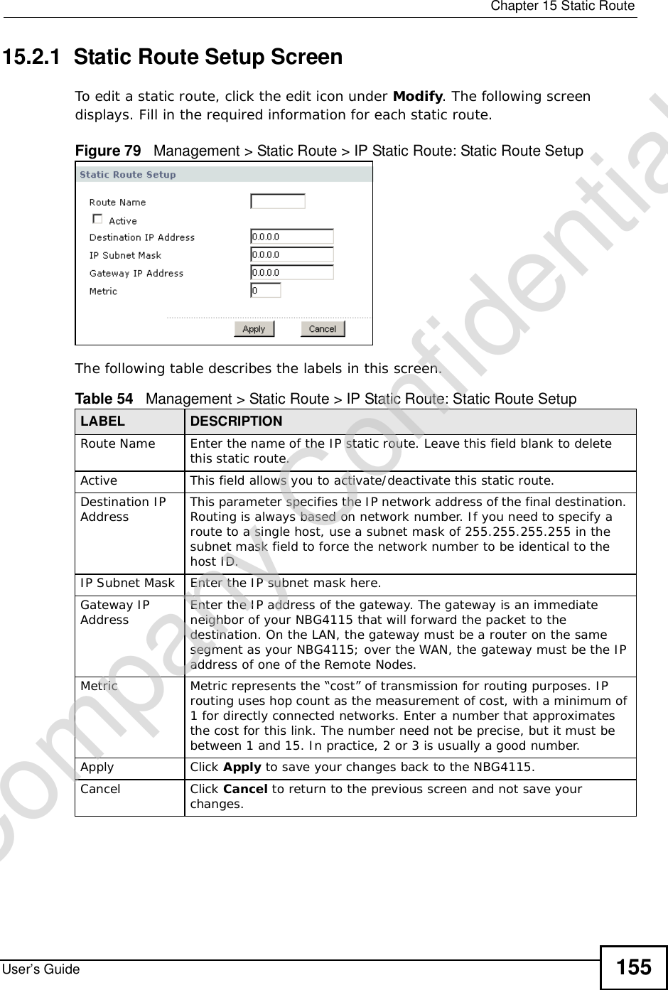
![Chapter 14Content FilteringUser’s Guide150For example, with the URL www.zyxel.com.tw/news/pressroom.php, content filtering only searches for keywords within www.zyxel.com.tw.Full Path URL CheckingFull path URL checking has the NBG4115 check the characters that come before the last slash in the URL.For example, with the URL www.zyxel.com.tw/news/pressroom.php, full path URL checking searches for keywords within www.zyxel.com.tw/news/.Use the ip urlfilter customize actionFlags 6 [disable | enable]command to extend (or not extend) the keyword blocking search to include the URL's full path.File Name URL CheckingFilename URL checking has the NBG4115 check all of the characters in the URL.For example, filename URL checking searches for keywords within the URL www.zyxel.com.tw/news/pressroom.php.Use the ip urlfilter customize actionFlags 8 [disable | enable] command to extend (or not extend) the keyword blocking search to include the URL's complete filename.Company Confidential](https://usermanual.wiki/ZyXEL-Communications/NBG417N.User-Manual/User-Guide-1164748-Page-149.png)


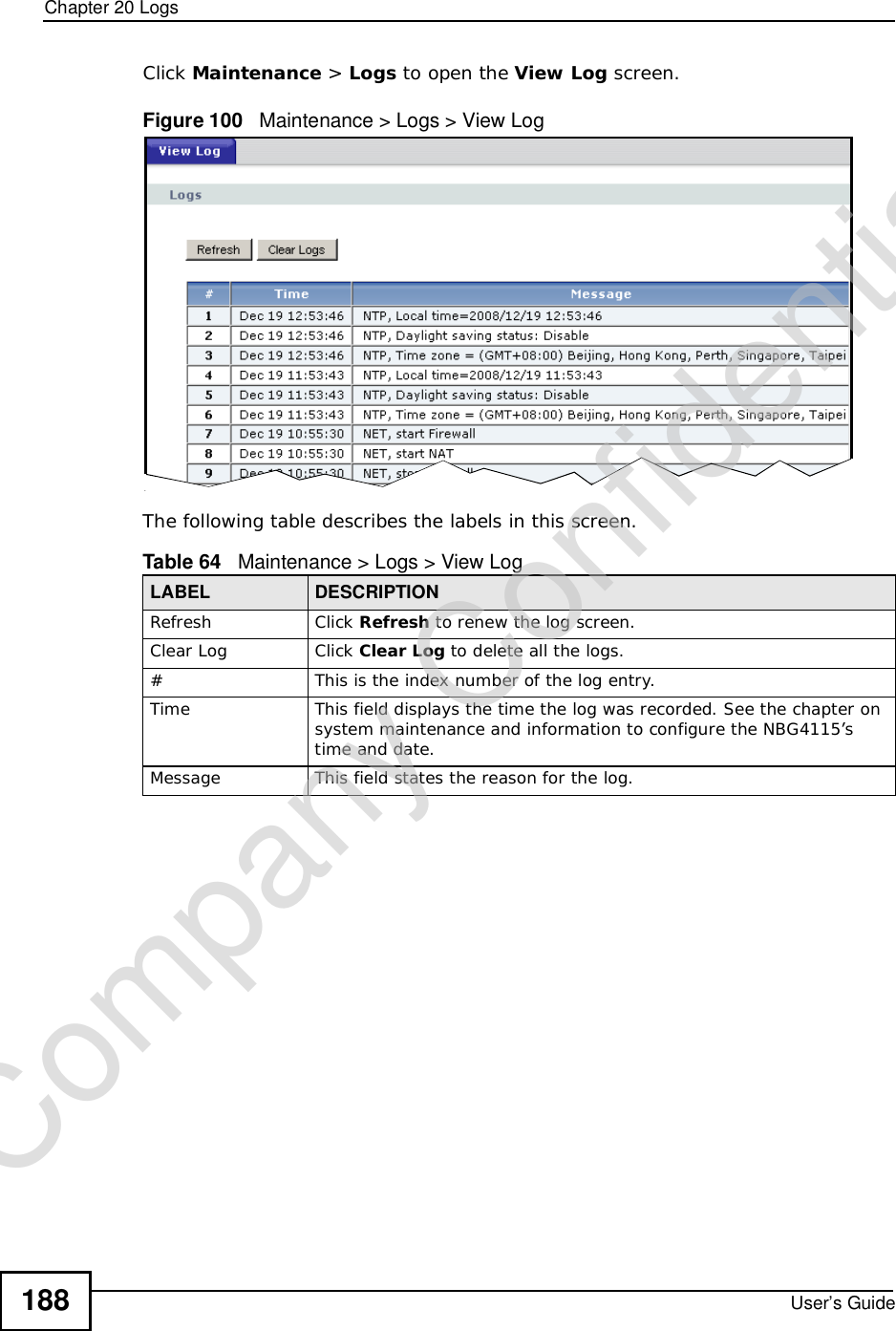


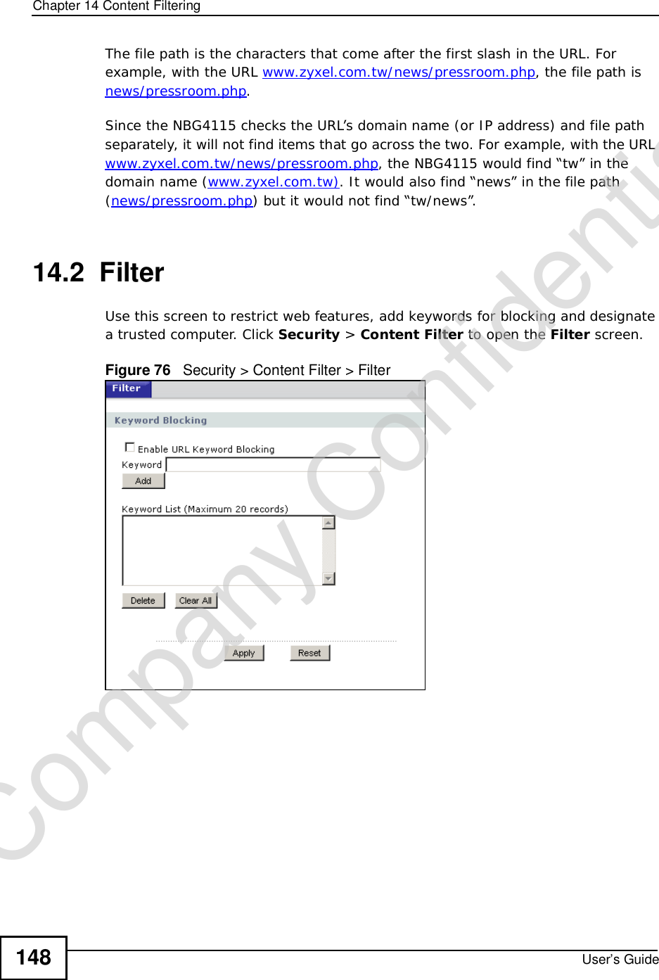
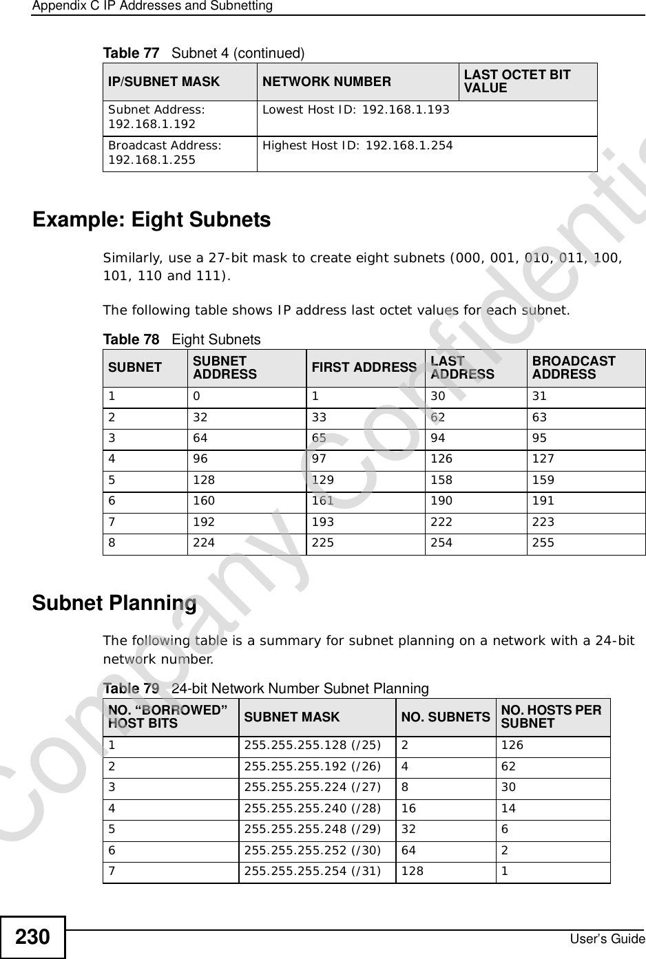
![Chapter 24TroubleshootingUser’s Guide204•If your computer is connected to the WAN port or is connected wirelessly, use a computer that is connected to a LAN/ETHERNET port.I can see the Login screen, but I cannot log in to the NBG4115.1Make sure you have entered the password correctly. The default password is 1234. This field is case-sensitive, so make sure [Caps Lock] is not on. 2You cannot log in to the Web Configurator while someone is using Telnet to access the NBG4115. Log out of the NBG4115 in the other session, or ask the person who is logged in to log out. 3This can happen when you fail to log out properly from your last session. Try logging in again after 5 minutes.4Disconnect and re-connect the power adaptor or cord to the NBG4115. 5If this does not work, you have to reset the device to its factory defaults. See Section 24.5 on page 206.24.4 Internet AccessI cannot access the Internet.1Check the hardware connections, and make sure the LEDs are behaving as expected. See the Quick Start Guide.2Make sure you entered your ISP account information correctly in the wizard. These fields are case-sensitive, so make sure [Caps Lock] is not on.3If you are trying to access the Internet wirelessly, make sure the wireless settings in the wireless client are the same as the settings in the AP.•Go to Network > Wireless LAN > General > WDS and check if the NBG4115 is set to bridge mode. Select Disable and try to connect to the Internet again.4Disconnect all the cables from your device, and follow the directions in the Quick Start Guide again. 5Go to Maintenance > Sys OP Mode > General. Check your System Operation Mode setting. Company Confidential](https://usermanual.wiki/ZyXEL-Communications/NBG417N.User-Manual/User-Guide-1164748-Page-203.png)


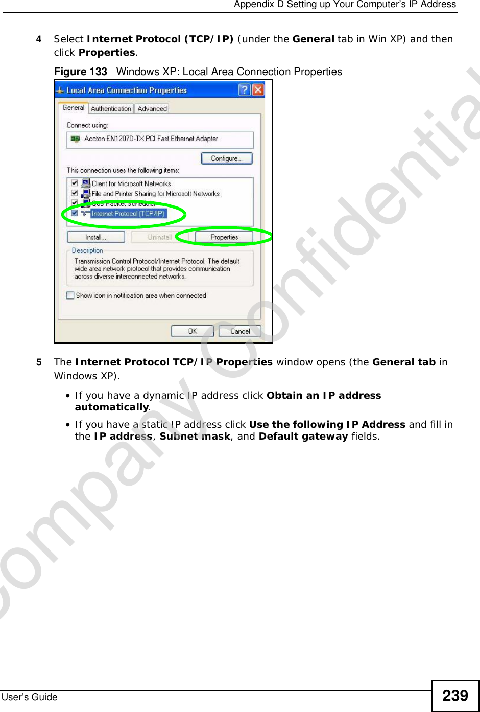
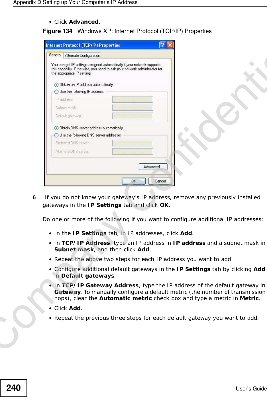
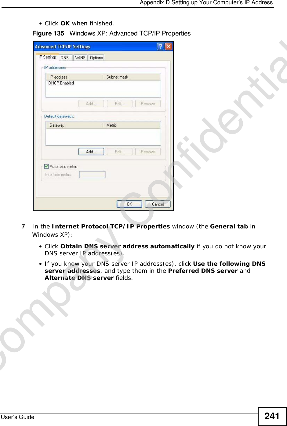
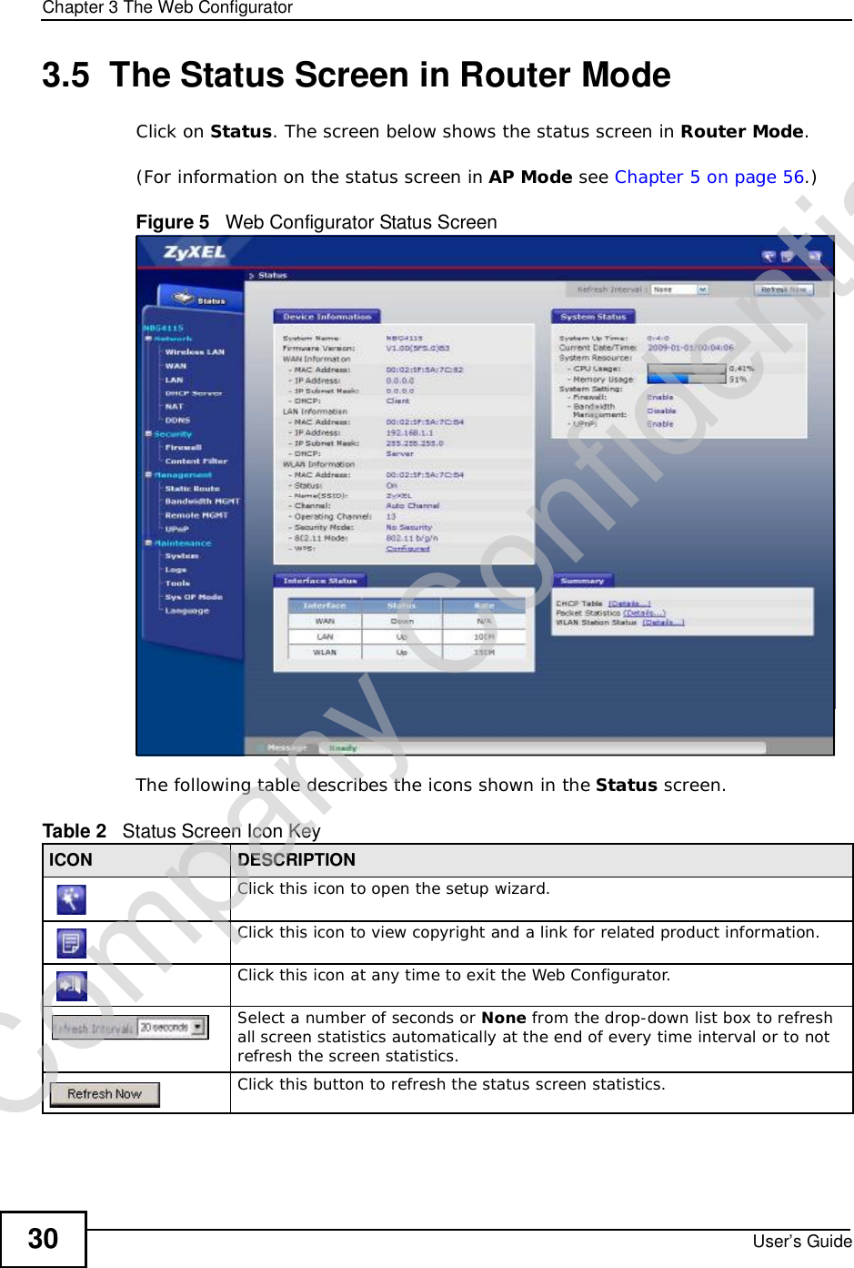
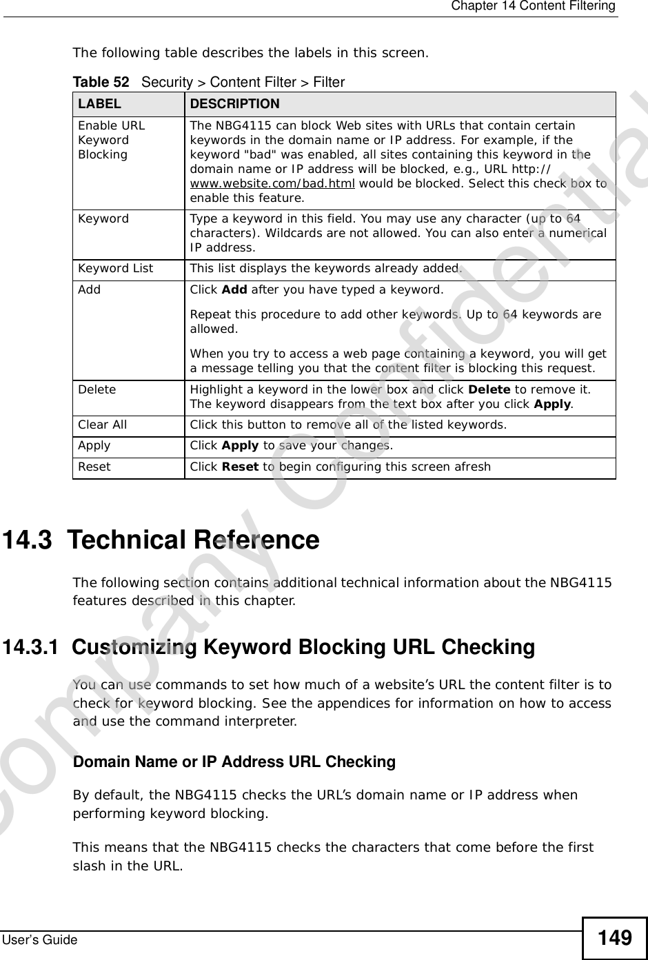
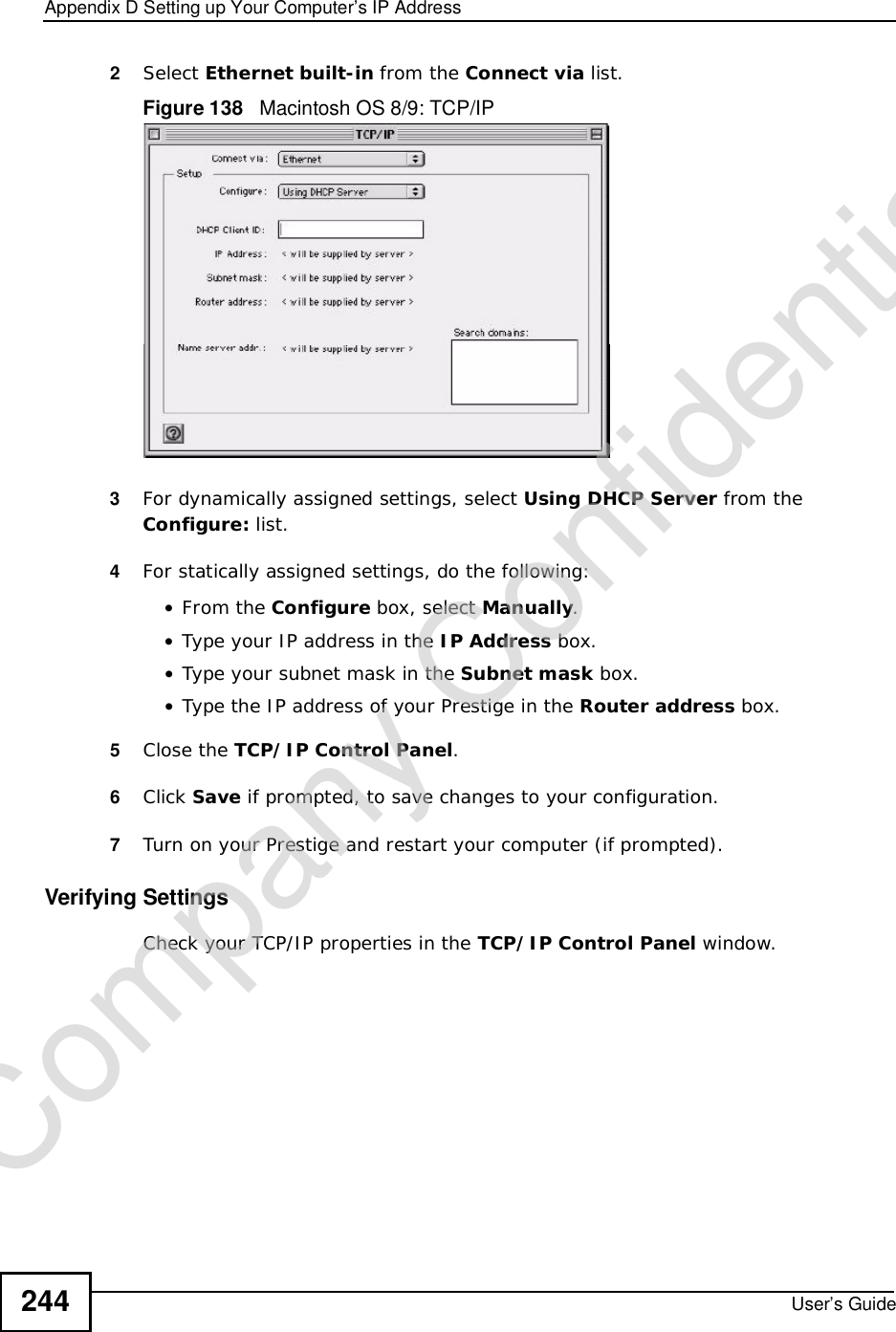
![Appendix DSetting up Your Computer’s IP AddressUser’s Guide242If you have previously configured DNS servers, click Advanced and then the DNS tab to order them.Figure 136 Windows XP: Internet Protocol (TCP/IP) Properties8Click OK to close the Internet Protocol (TCP/IP) Properties window.9Click Close (OK in Windows 2000/NT) to close the Local Area Connection Properties window.10 Close the Network Connections window (Network and Dial-up Connections in Windows 2000/NT).11 Turn on your Prestige and restart your computer (if prompted).Verifying Settings1Click Start,All Programs,Accessories and then Command Prompt.2In the Command Prompt window, type "ipconfig" and then press [ENTER]. You can also open Network Connections, right-click a network connection, click Status and then click the Support tab.Company Confidential](https://usermanual.wiki/ZyXEL-Communications/NBG417N.User-Manual/User-Guide-1164748-Page-241.png)
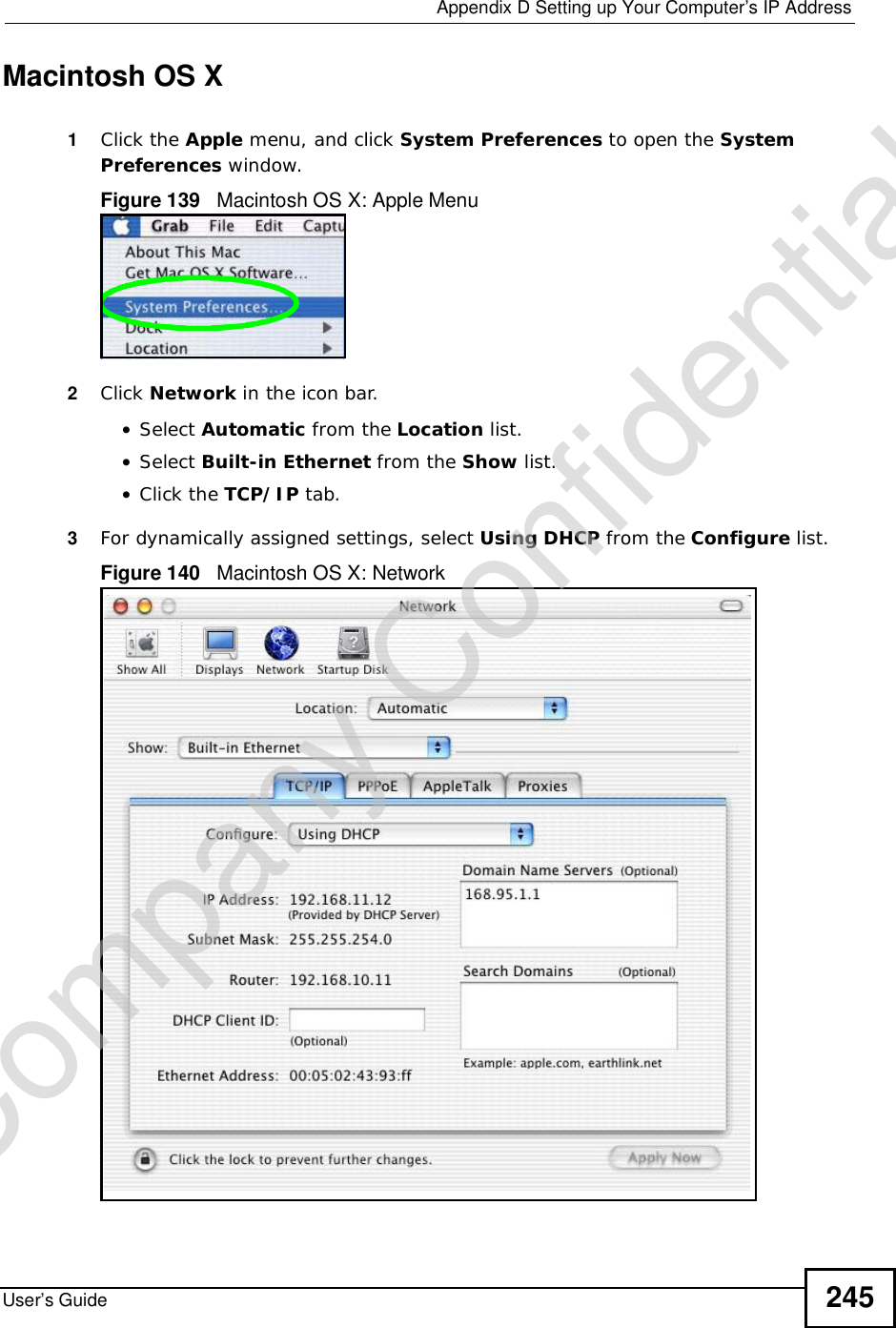
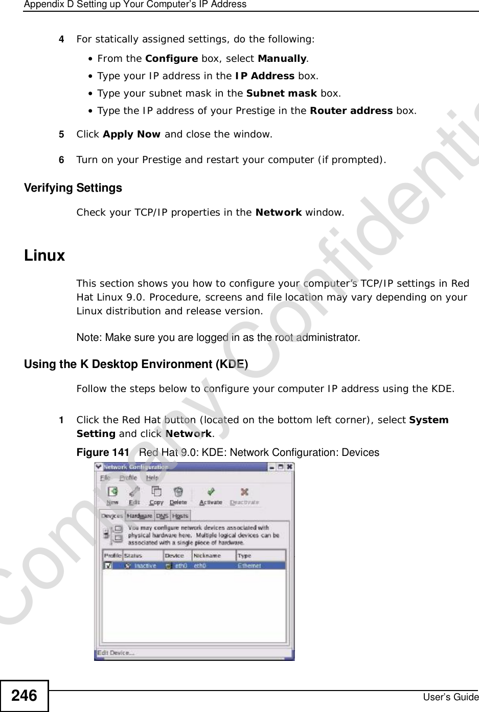
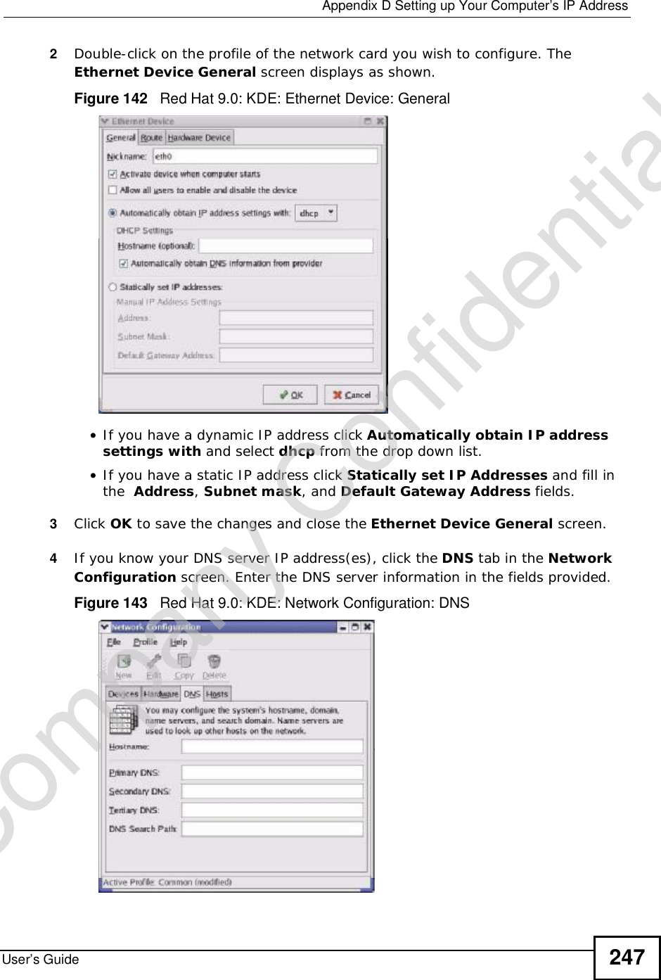
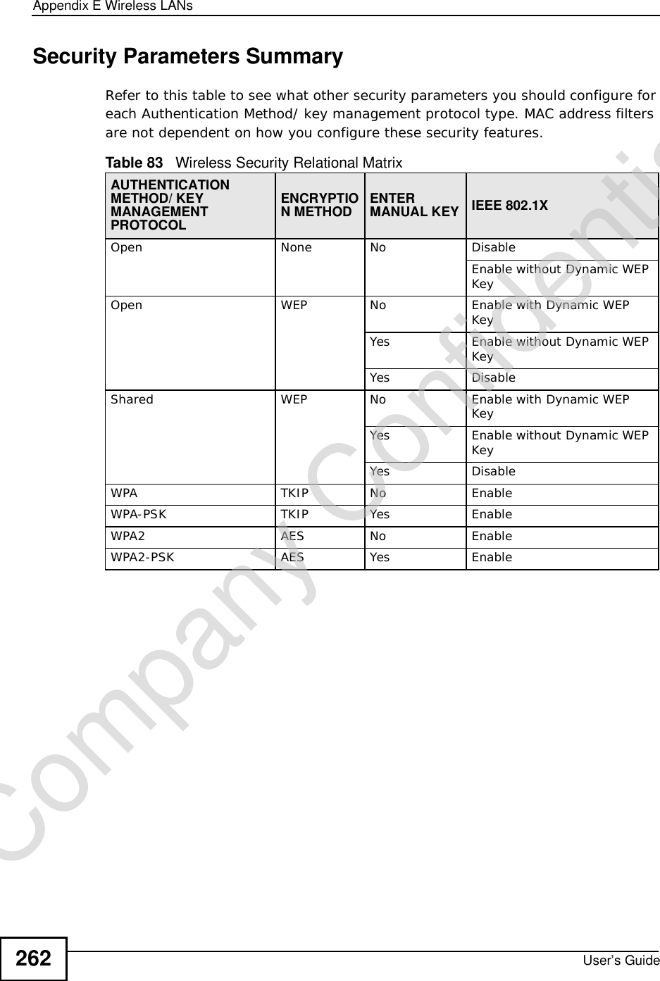
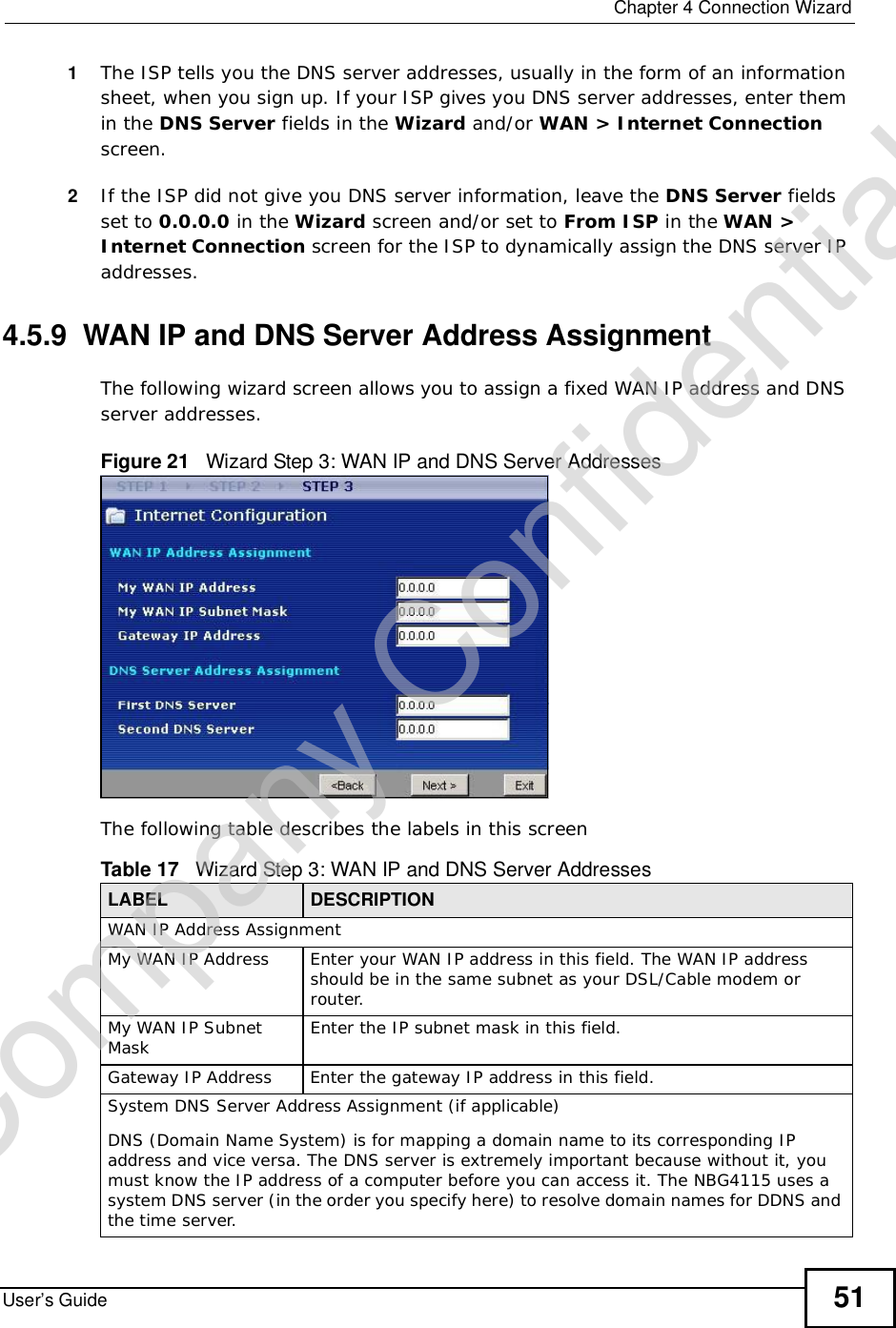
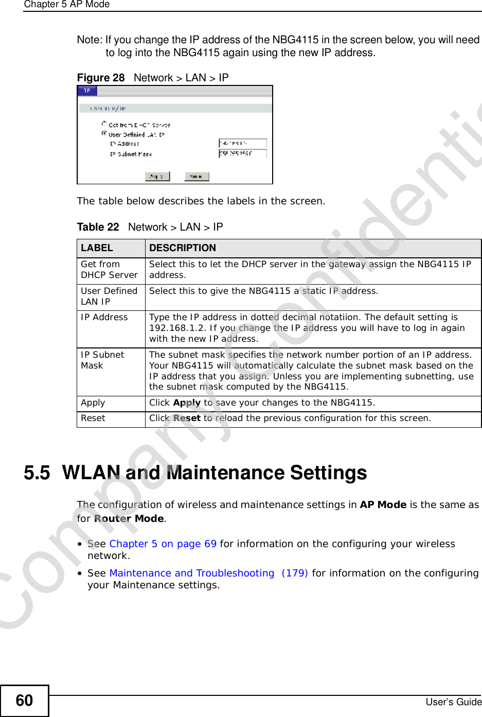
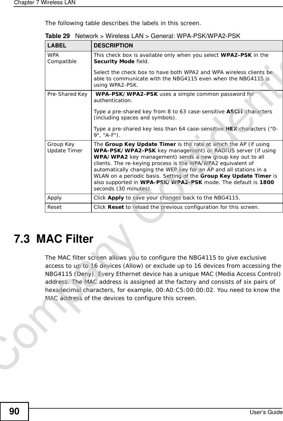
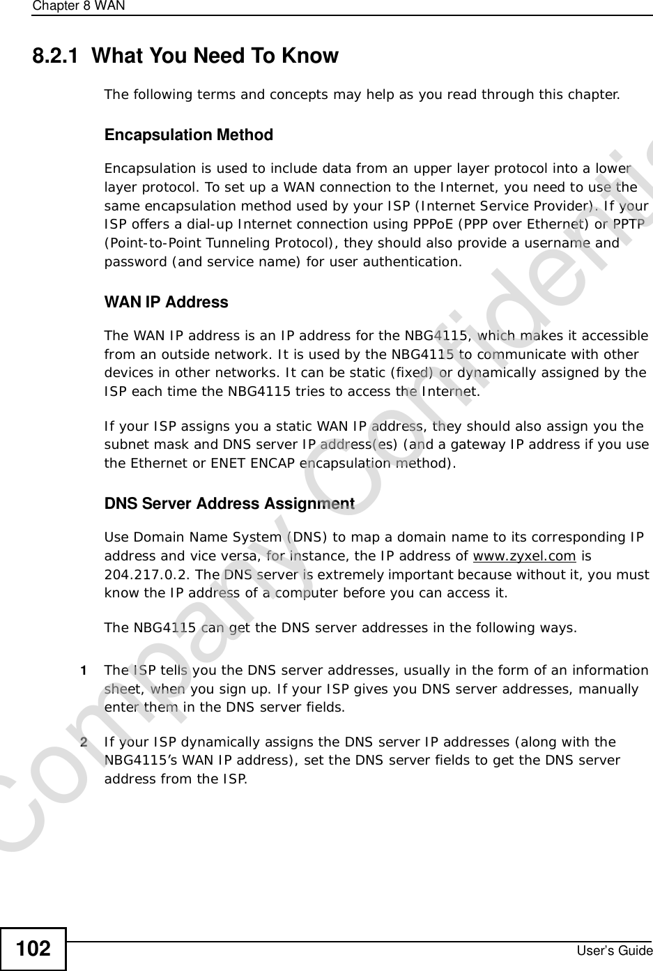
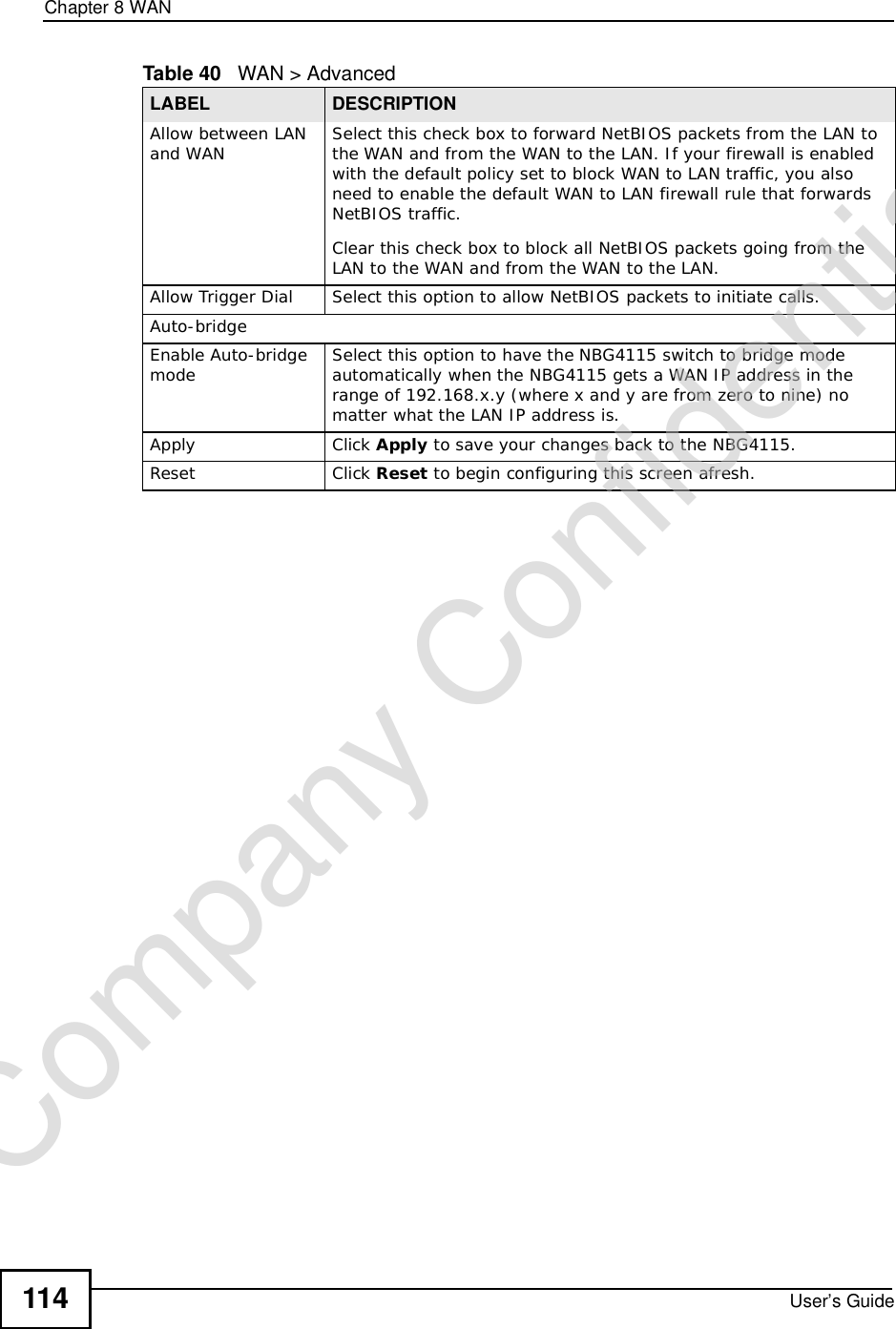
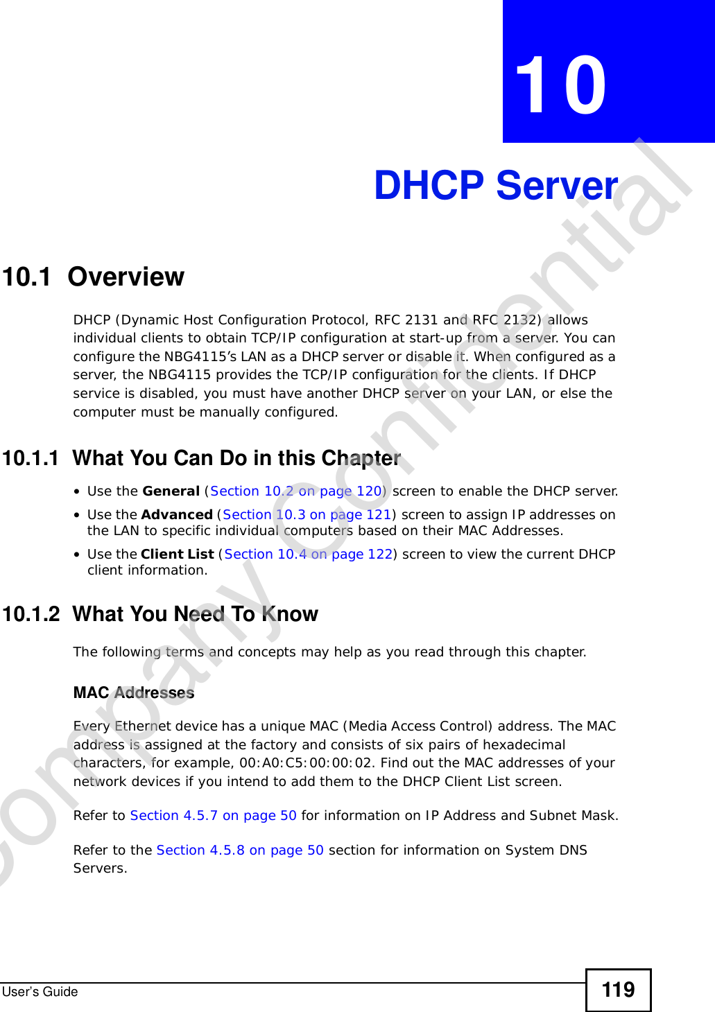
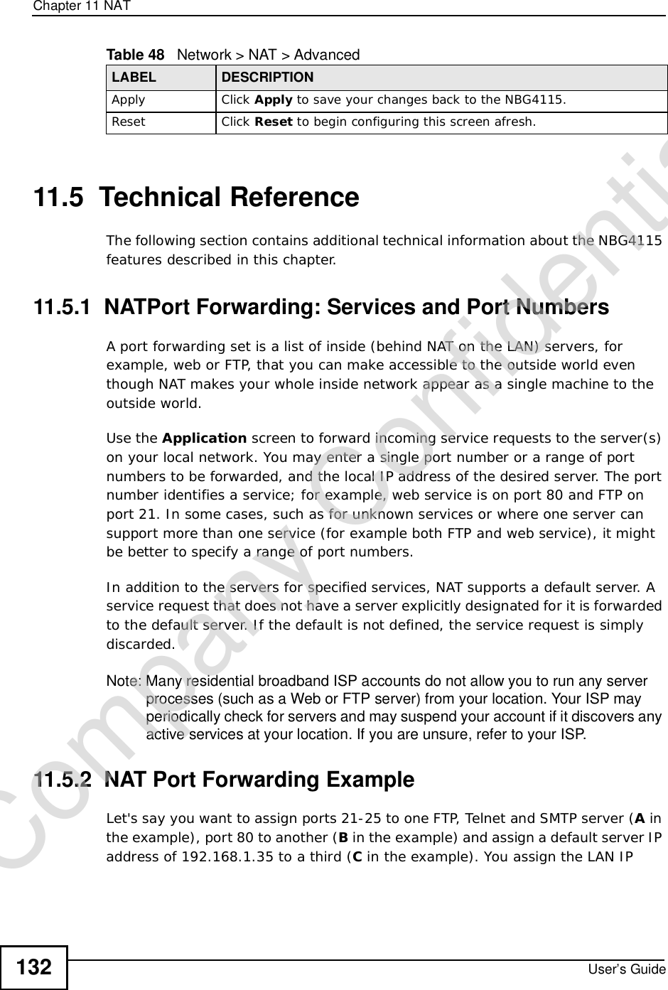
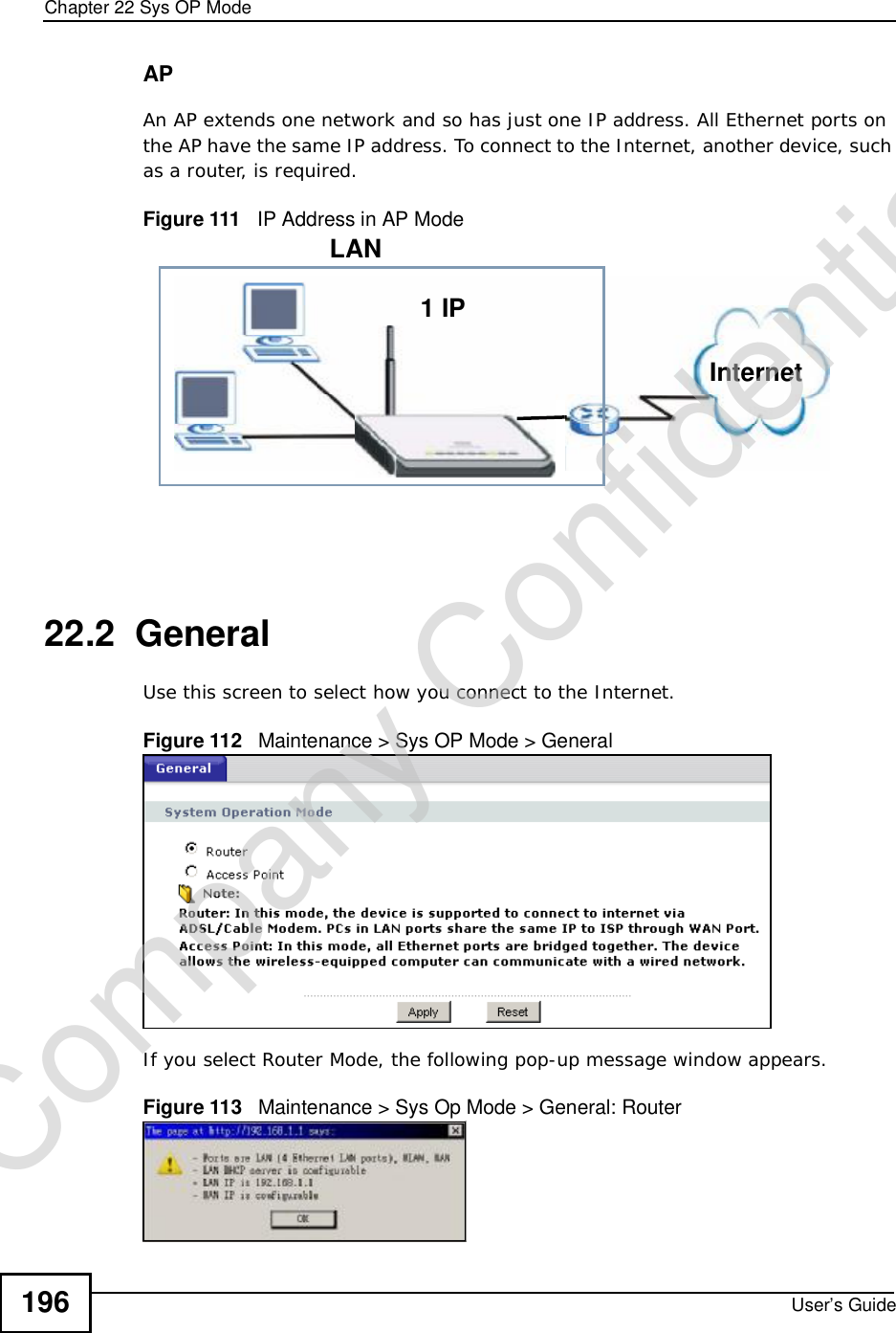
![Appendix DSetting up Your Computer’s IP AddressUser’s Guide 249•If you have a static IP address, enter static in the BOOTPROTO= field. Type IPADDR= followed by the IP address (in dotted decimal notation) and type NETMASK= followed by the subnet mask. The following example shows an example where the static IP address is 192.168.1.10 and the subnet mask is 255.255.255.0. Figure 146 Red Hat 9.0: Static IP Address Setting in ifconfig-eth0 2If you know your DNS server IP address(es), enter the DNS server information in the resolv.conf file in the /etc directory. The following figure shows an example where two DNS server IP addresses are specified.Figure 147 Red Hat 9.0: DNS Settings in resolv.conf 3After you edit and save the configuration files, you must restart the network card. Enter./network restart in the /etc/rc.d/init.d directory. The following figure shows an example.Figure 148 Red Hat 9.0: Restart Ethernet Card DEVICE=eth0ONBOOT=yesBOOTPROTO=staticIPADDR=192.168.1.10NETMASK=255.255.255.0USERCTL=noPEERDNS=yesTYPE=Ethernetnameserver 172.23.5.1nameserver 172.23.5.2[root@localhost init.d]# network restartShutting down interface eth0: [OK]Shutting down loopback interface: [OK]Setting network parameters: [OK]Bringing up loopback interface: [OK]Bringing up interface eth0: [OK]Company Confidential](https://usermanual.wiki/ZyXEL-Communications/NBG417N.User-Manual/User-Guide-1164748-Page-248.png)
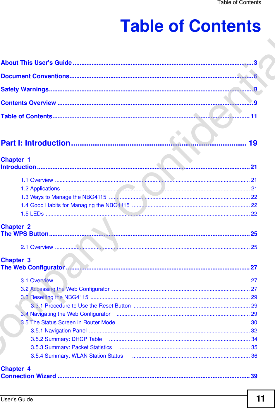
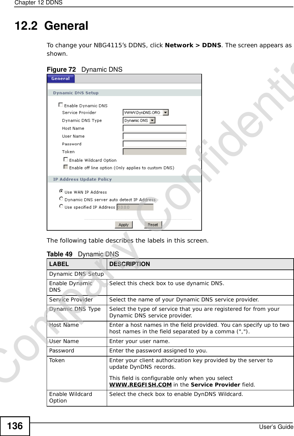
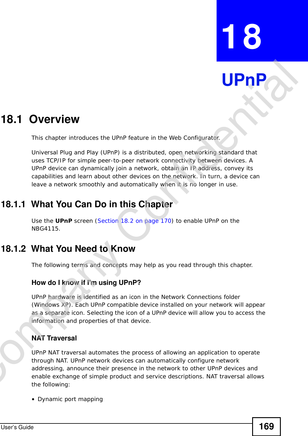
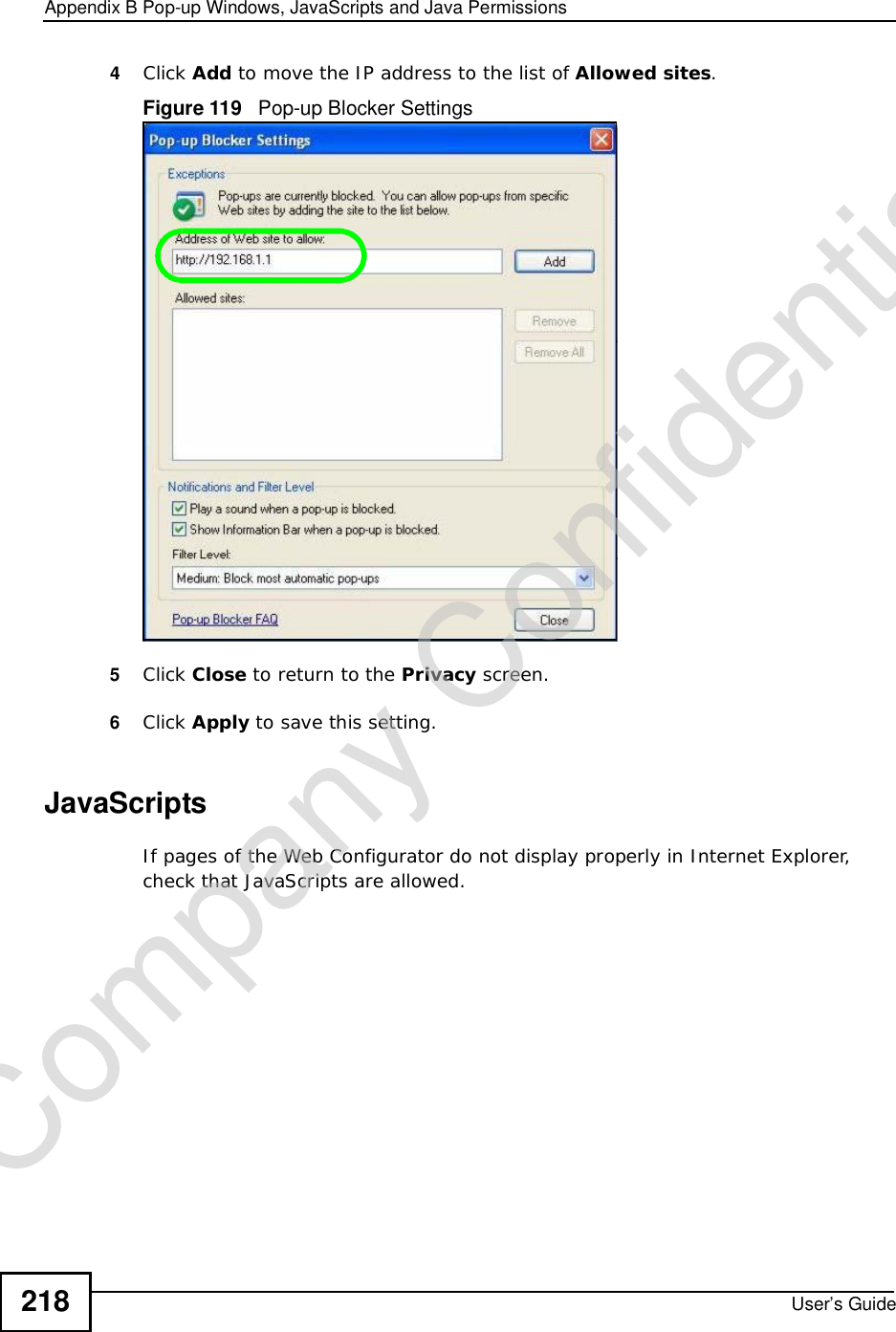
![Appendix DSetting up Your Computer’s IP AddressUser’s Guide25024.6.1 Verifying SettingsEnter ifconfig in a terminal screen to check your TCP/IP properties. Figure 149 Red Hat 9.0: Checking TCP/IP Properties [root@localhost]# ifconfig eth0 Link encap:Ethernet HWaddr 00:50:BA:72:5B:44 inet addr:172.23.19.129 Bcast:172.23.19.255 Mask:255.255.255.0 UP BROADCAST RUNNING MULTICAST MTU:1500 Metric:1 RX packets:717 errors:0 dropped:0 overruns:0 frame:0 TX packets:13 errors:0 dropped:0 overruns:0 carrier:0 collisions:0 txqueuelen:100 RX bytes:730412 (713.2 Kb) TX bytes:1570 (1.5 Kb) Interrupt:10 Base address:0x1000 [root@localhost]#Company Confidential](https://usermanual.wiki/ZyXEL-Communications/NBG417N.User-Manual/User-Guide-1164748-Page-249.png)