ZyXEL Communications NBG419N Wireless N Home Router, Wireless N Access Point User Manual NBG 419N
ZyXEL Communications Corporation Wireless N Home Router, Wireless N Access Point NBG 419N
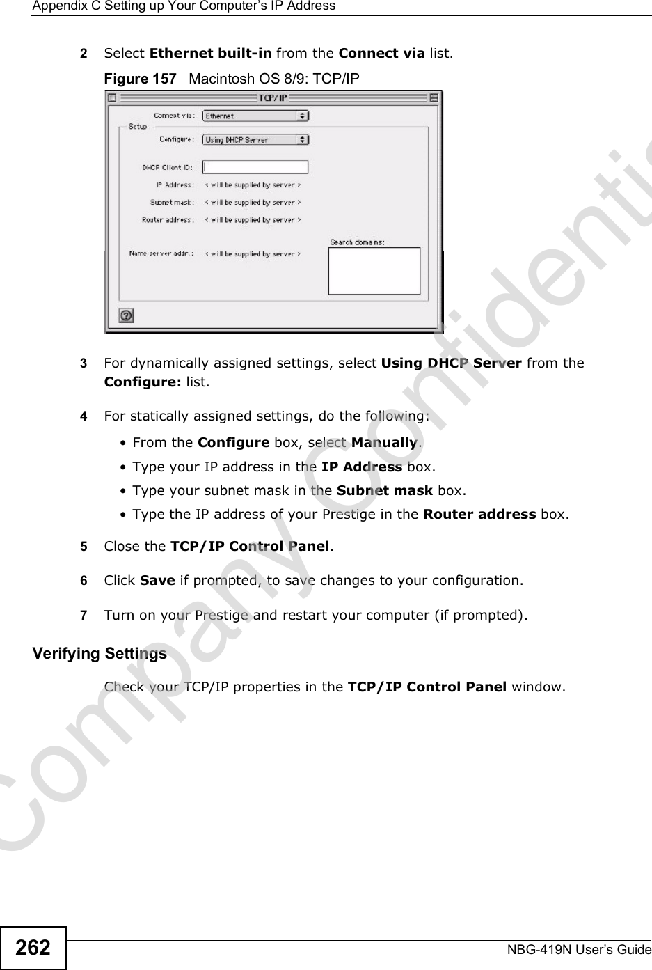
UserManual.wiki
>
ZyXEL Communications
>
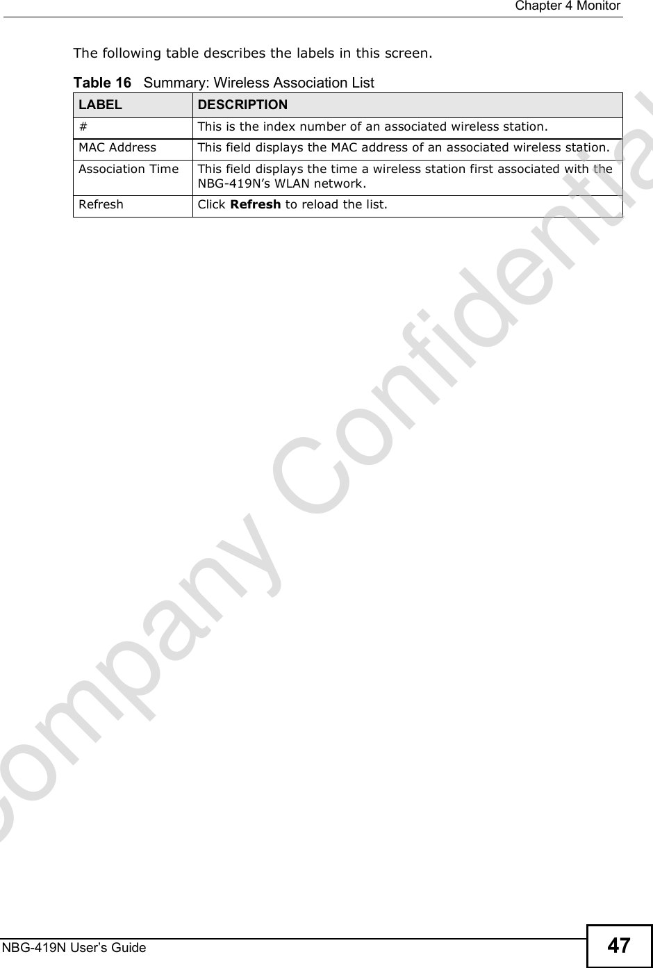
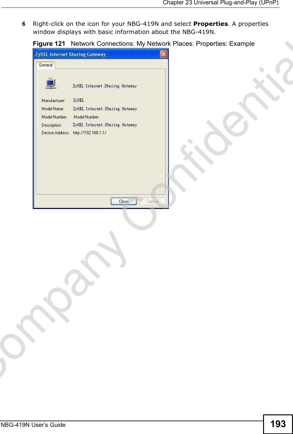
NBG419N User Manual
Manual
Navigation menu
Upload a User Manual
Namespaces
Wiki Guide
HTML
PDF
Info
Views
User Manual
Discussion / Help
Navigation

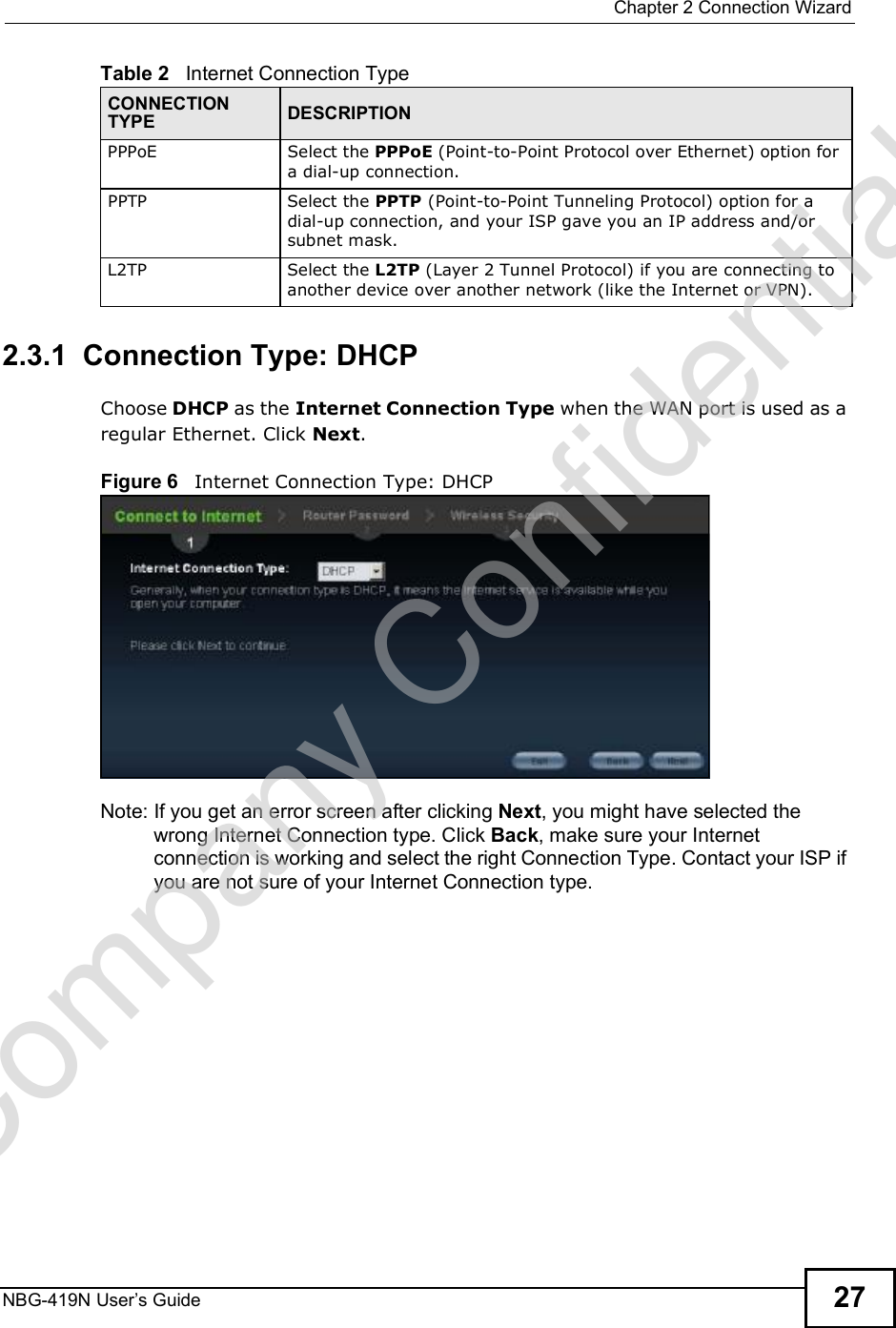
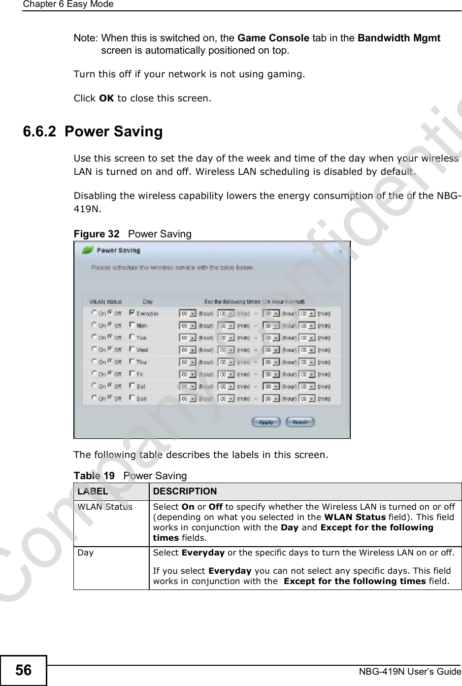
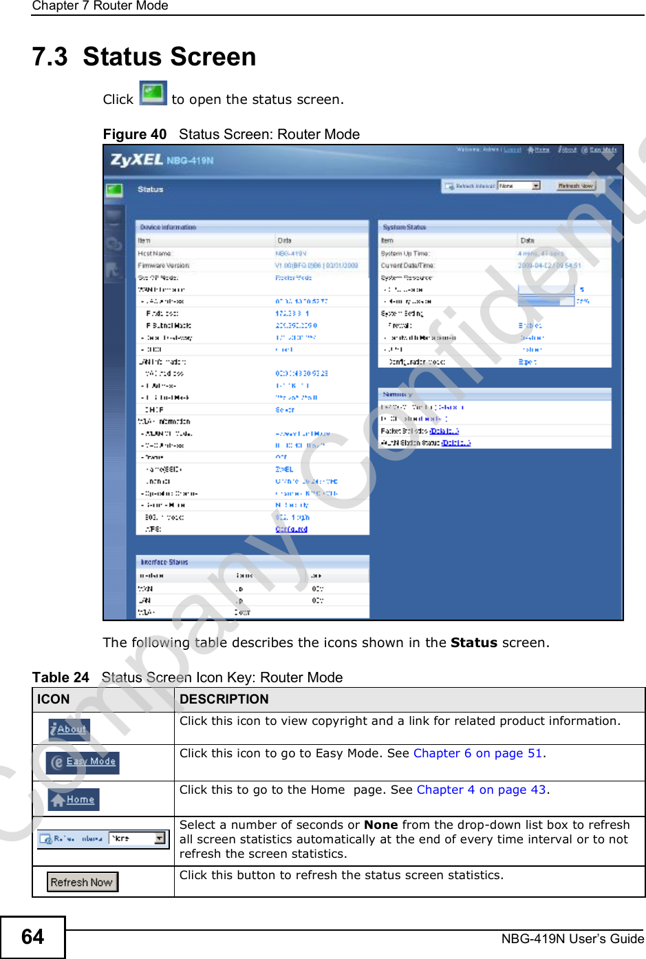
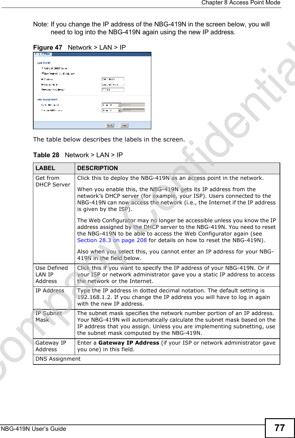
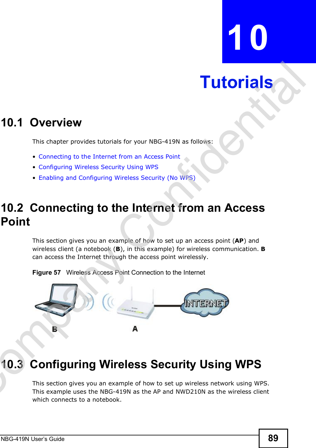
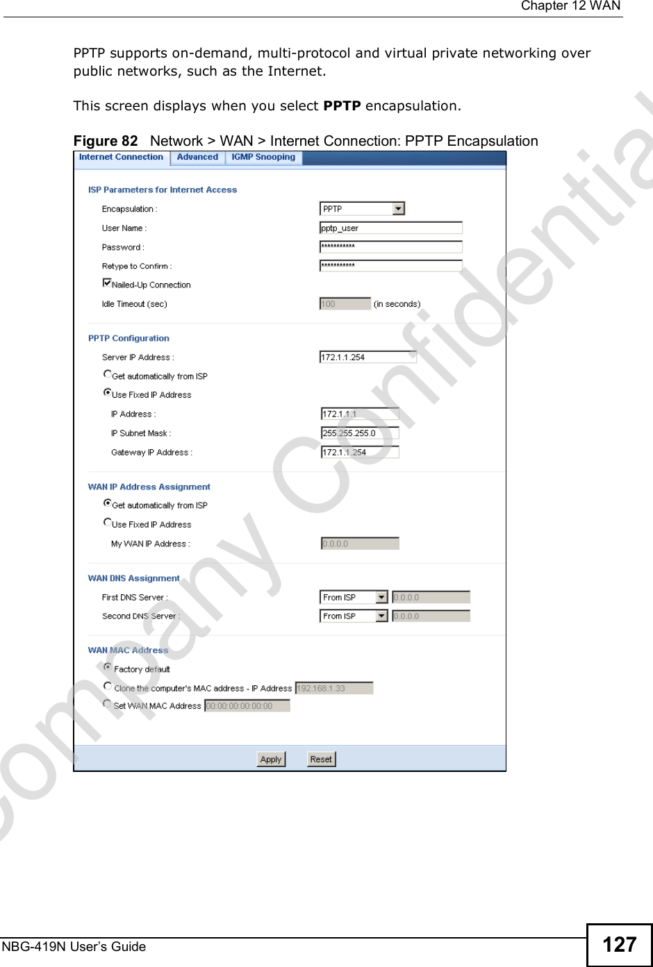
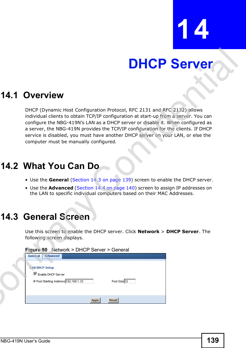
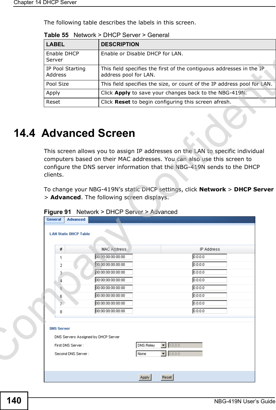
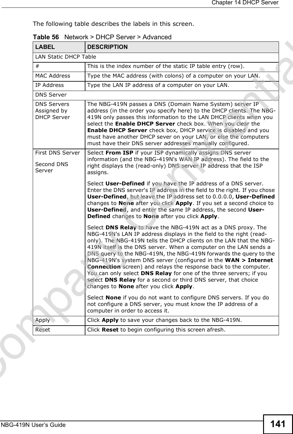
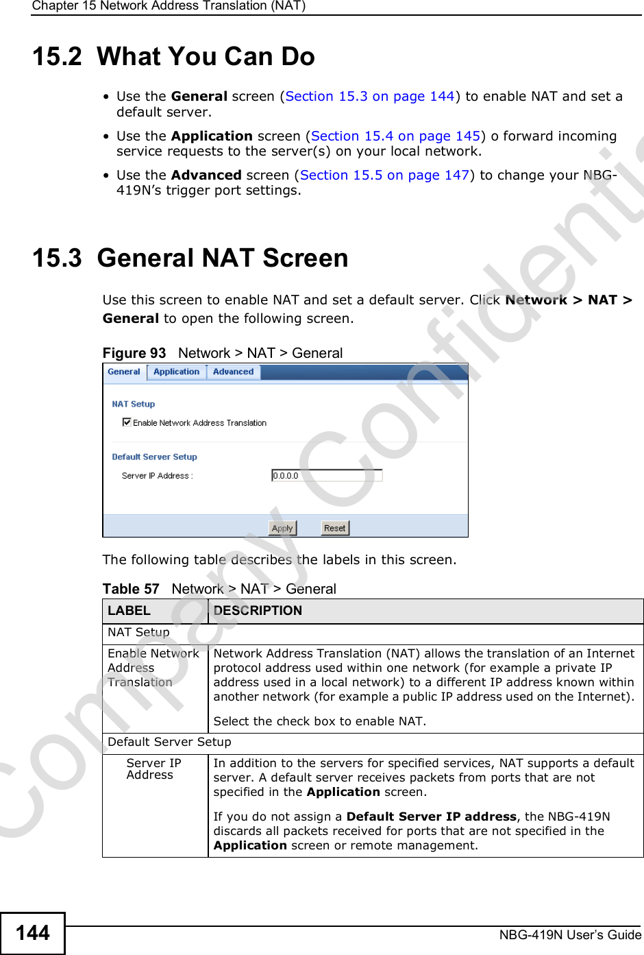
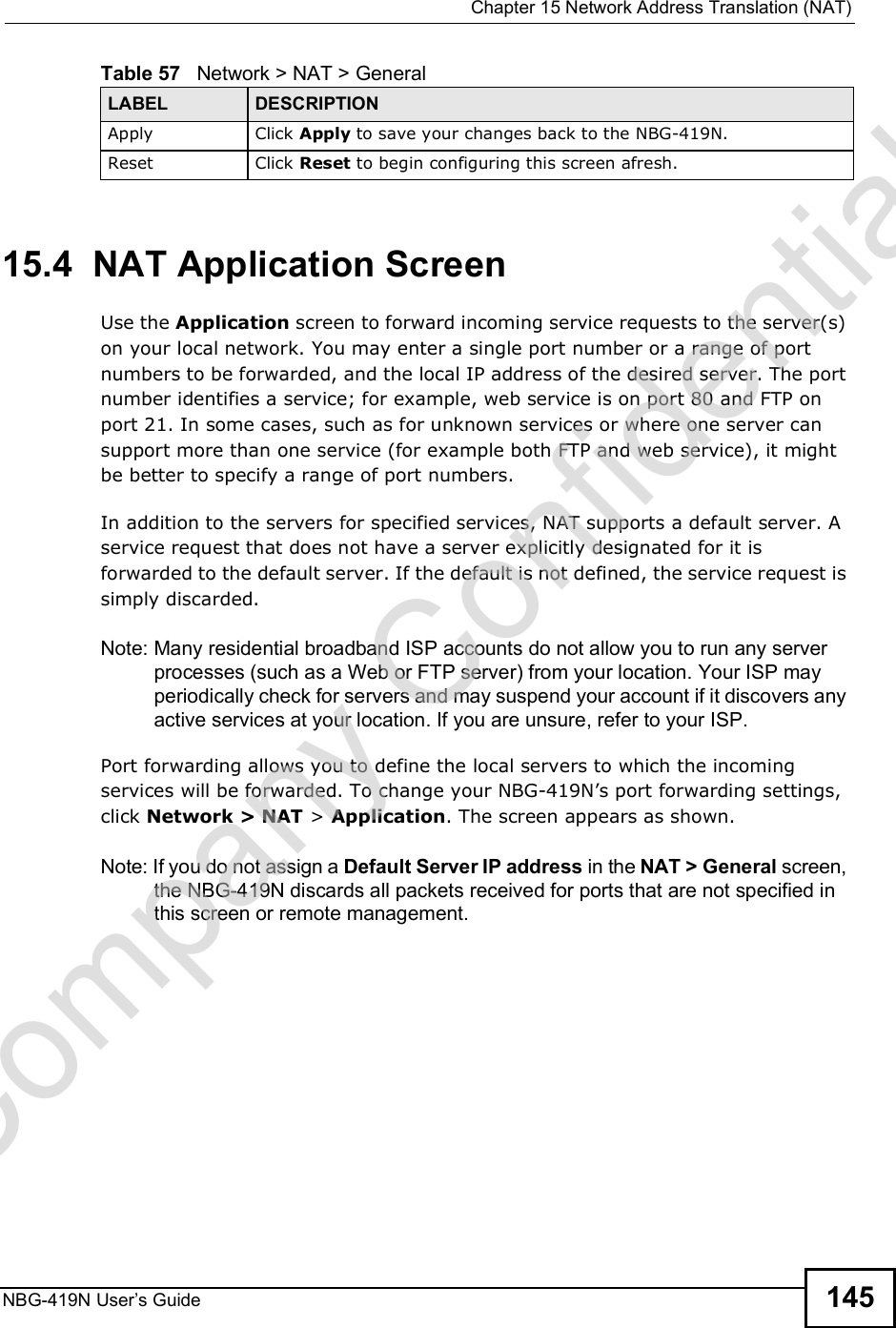
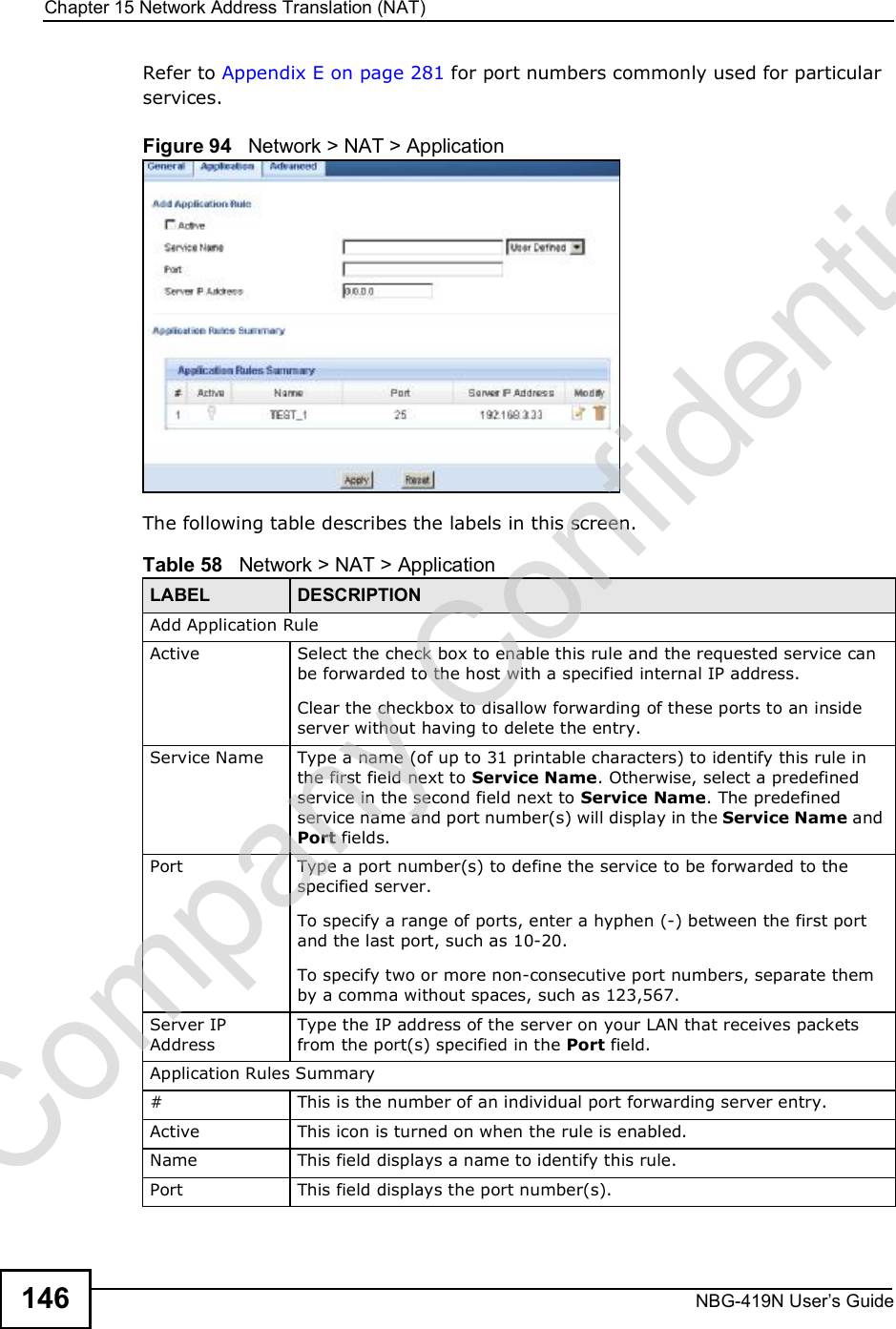
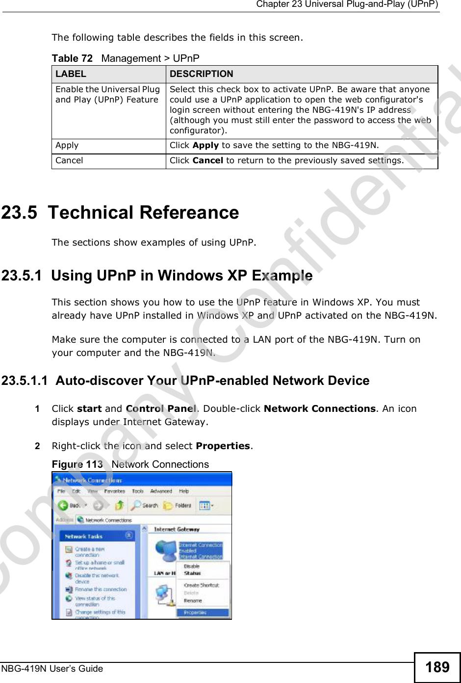
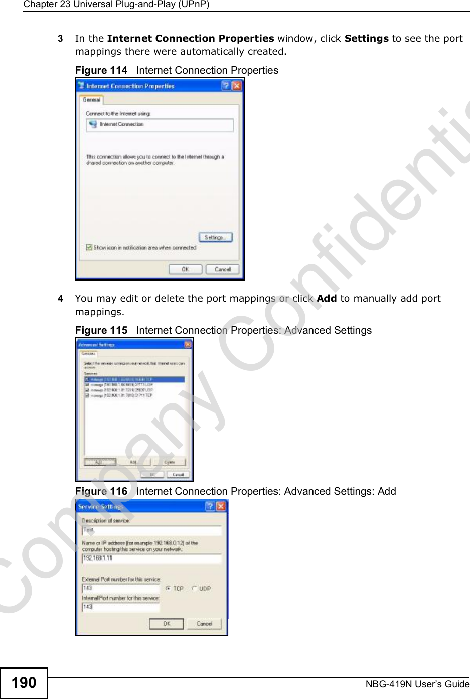
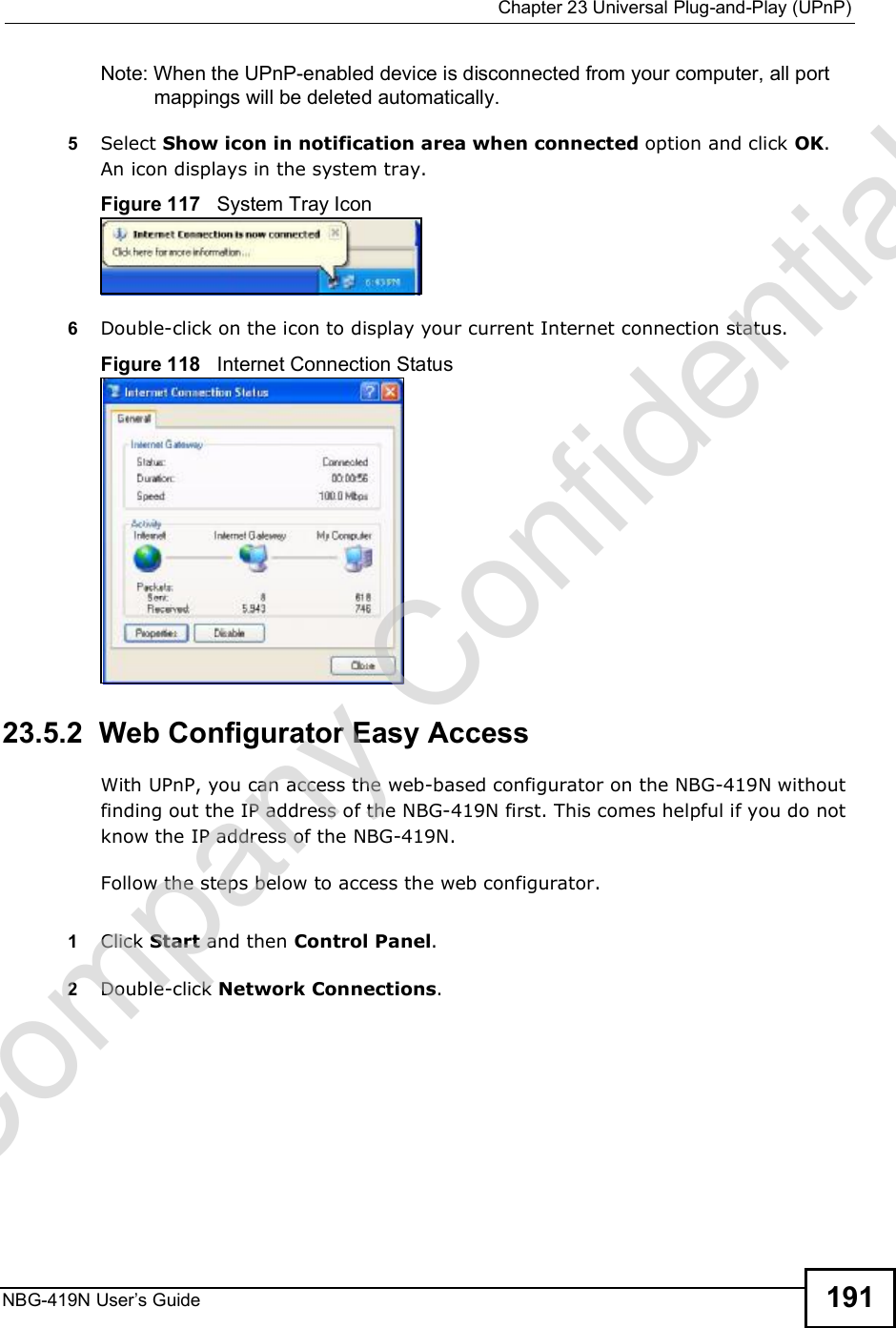
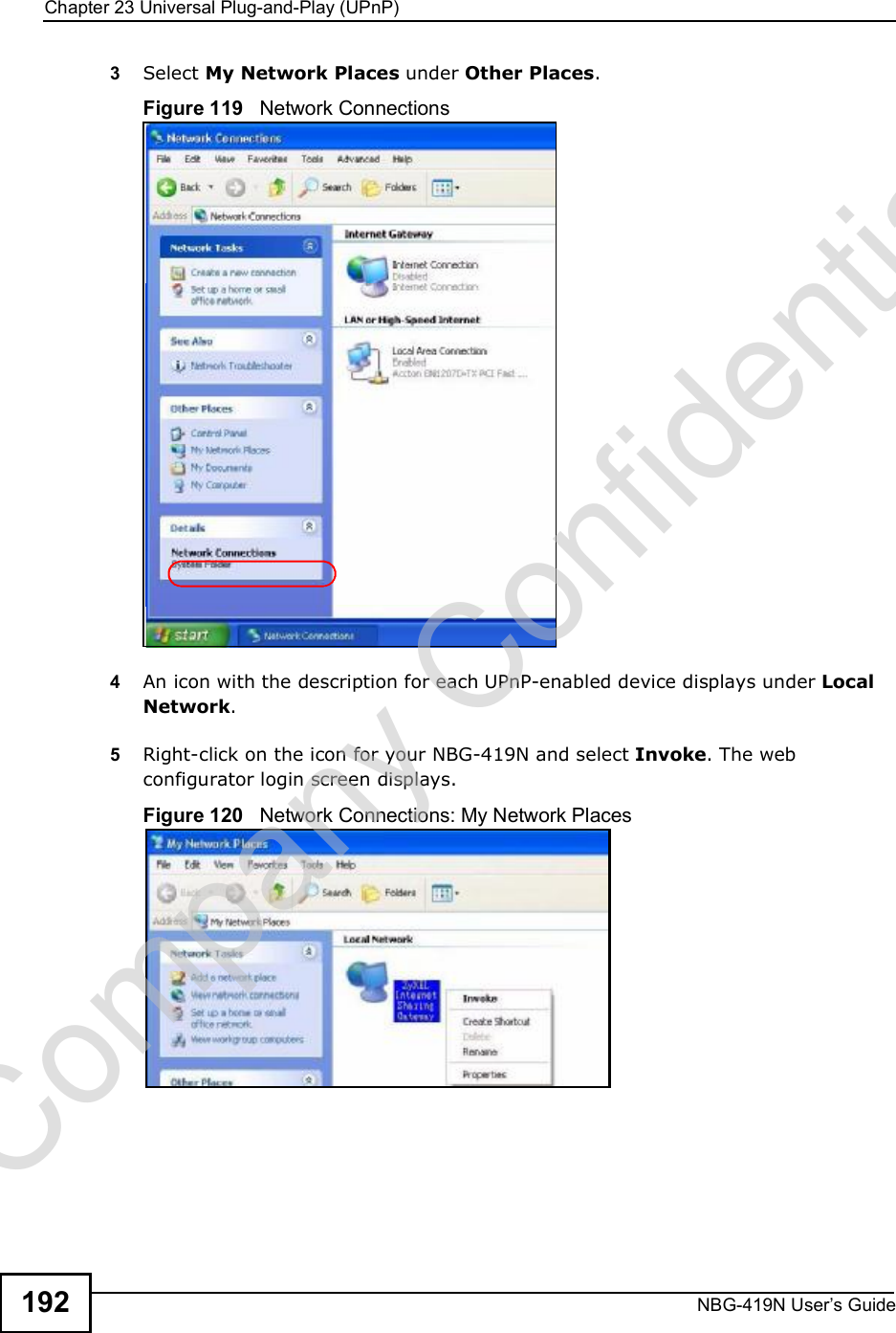
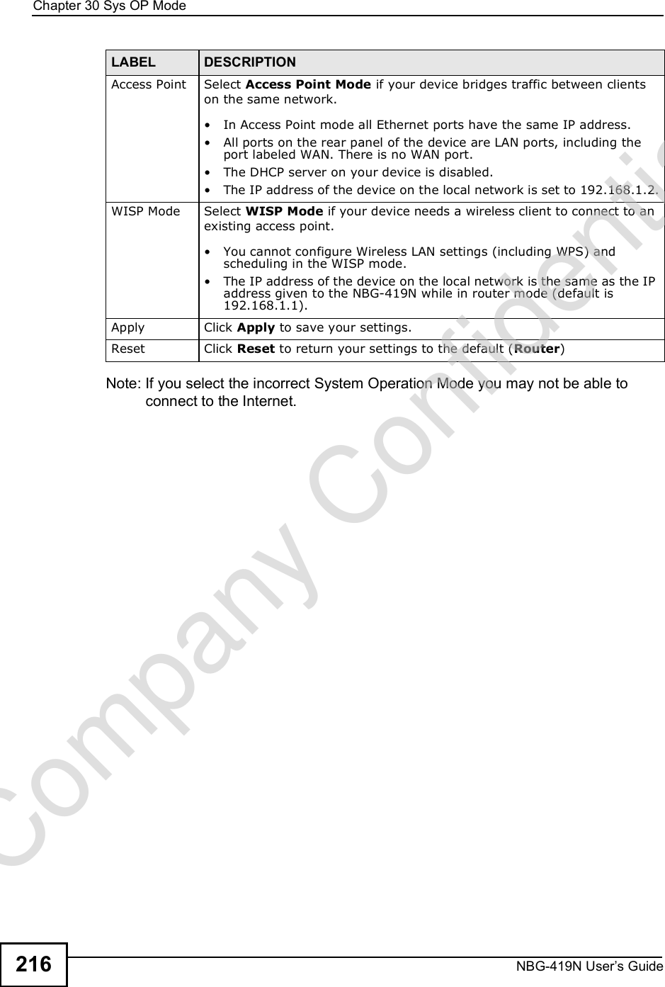
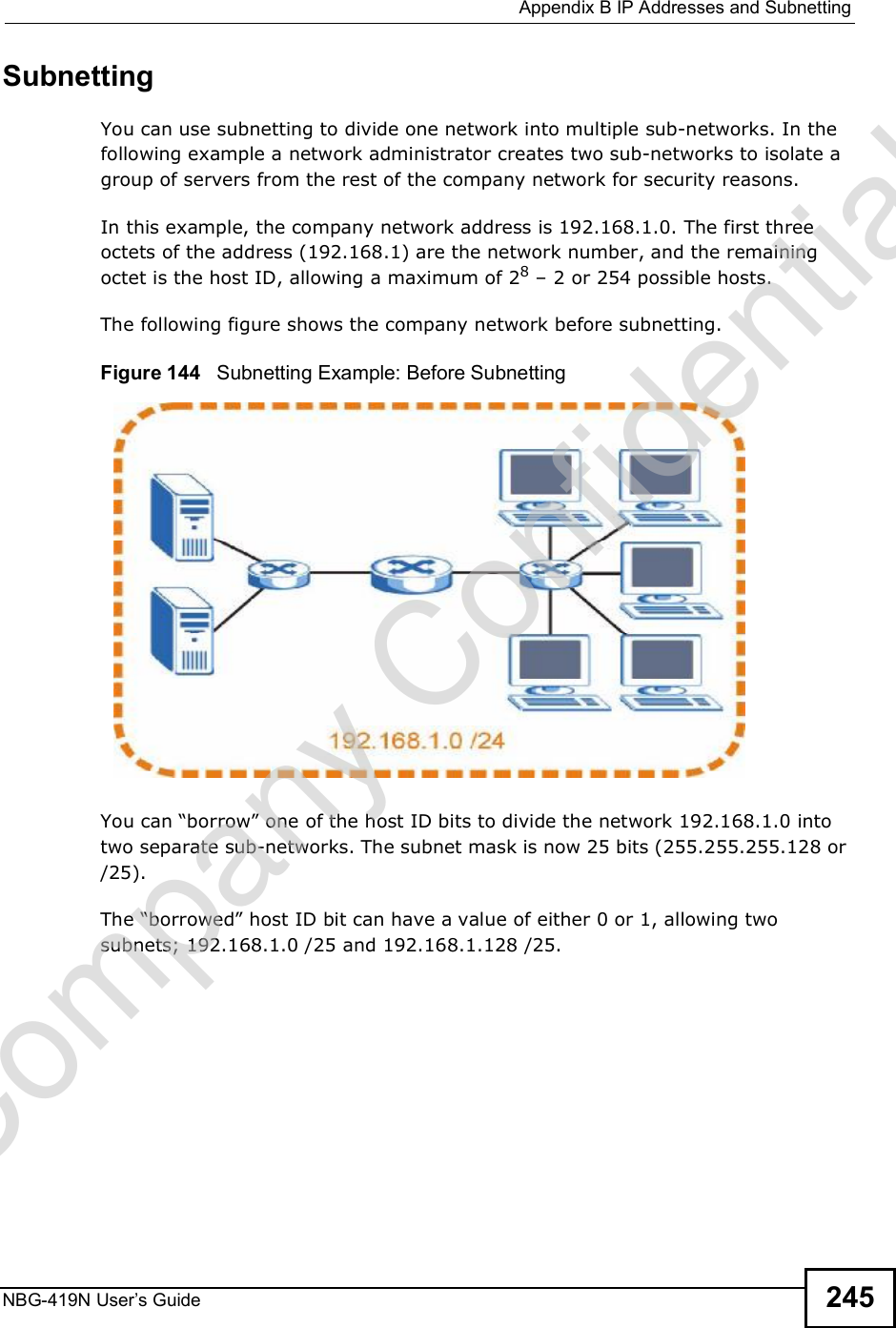
![Document ConventionsNBG-419N User s Guide 5Document ConventionsWarnings and NotesThese are how warnings and notes are shown in this User!s Guide. Warnings tell you about things that could harm you or your device.Note: Notes tell you other important information (for example, other things you may need to configure or helpful tips) or recommendations.Syntax Conventions The NBG-419N may be referred to as the "NBG-419N#, the "device#, the "product# or the "system# in this User!s Guide. Product labels, screen names, field labels and field choices are all in bold font. A key stroke is denoted by square brackets and uppercase text, for example, [ENTER] means the "enter# or "return# key on your keyboard. "Enter# means for you to type one or more characters and then press the [ENTER] key. "Select# or "choose# means for you to use one of the predefined choices. A right angle bracket ( > ) within a screen name denotes a mouse click. For example, Maintenance > Log > Log Setting means you first click Maintenance in the navigation panel, then the Log sub menu and finally the Log Setting tab to get to that screen. Units of measurement may denote the "metric# value or the "scientific# value. For example, "k# for kilo may denote "1000# or "1024#, "M# for mega may denote "1000000# or "1048576# and so on. "e.g.,# is a shorthand for "for instance#, and "i.e.,# means "that is# or "in other words#.Company Confidential](https://usermanual.wiki/ZyXEL-Communications/NBG419N/User-Guide-1180986-Page-5.png)


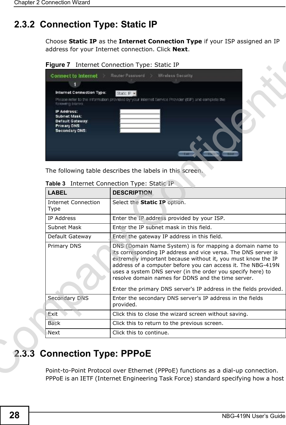

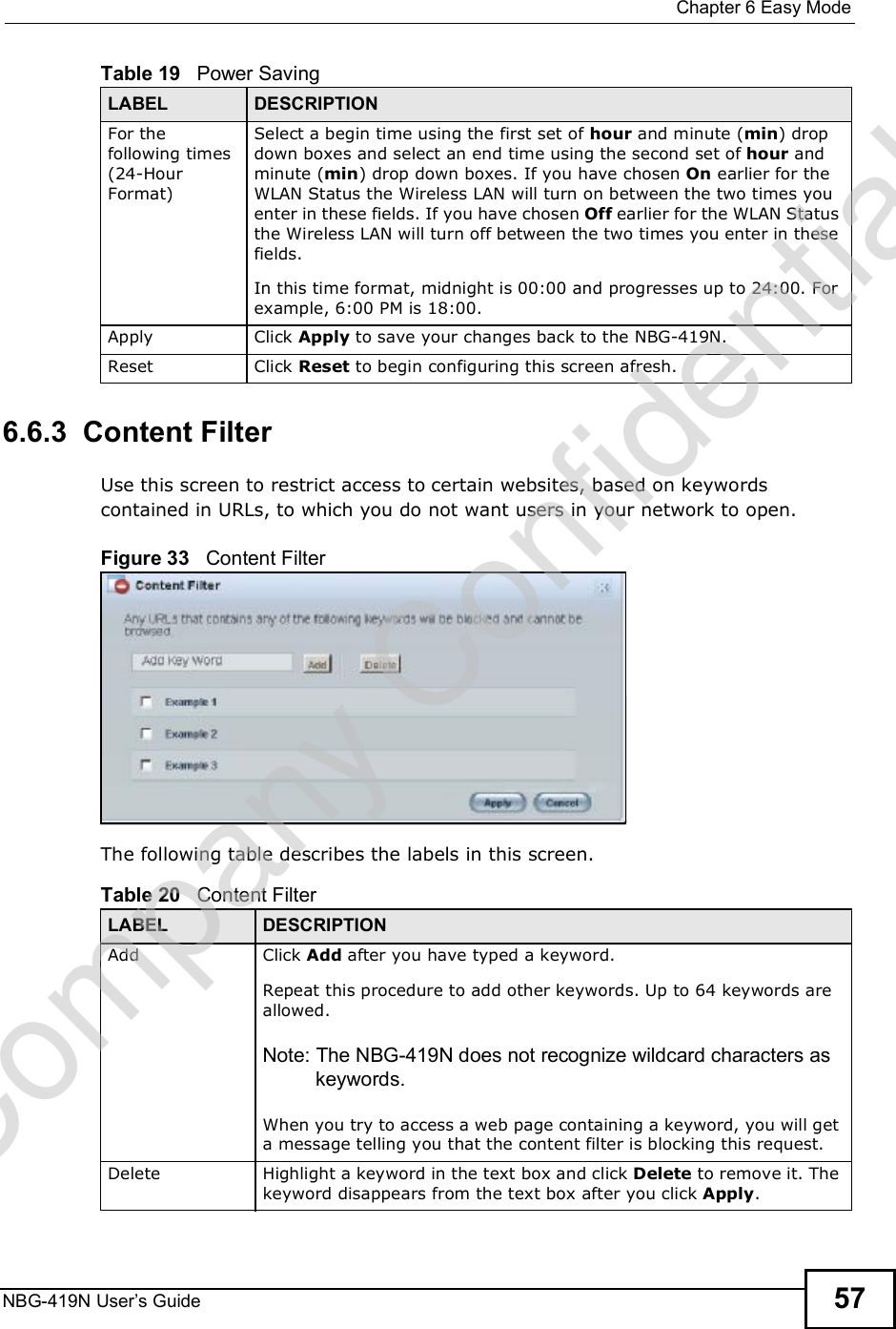
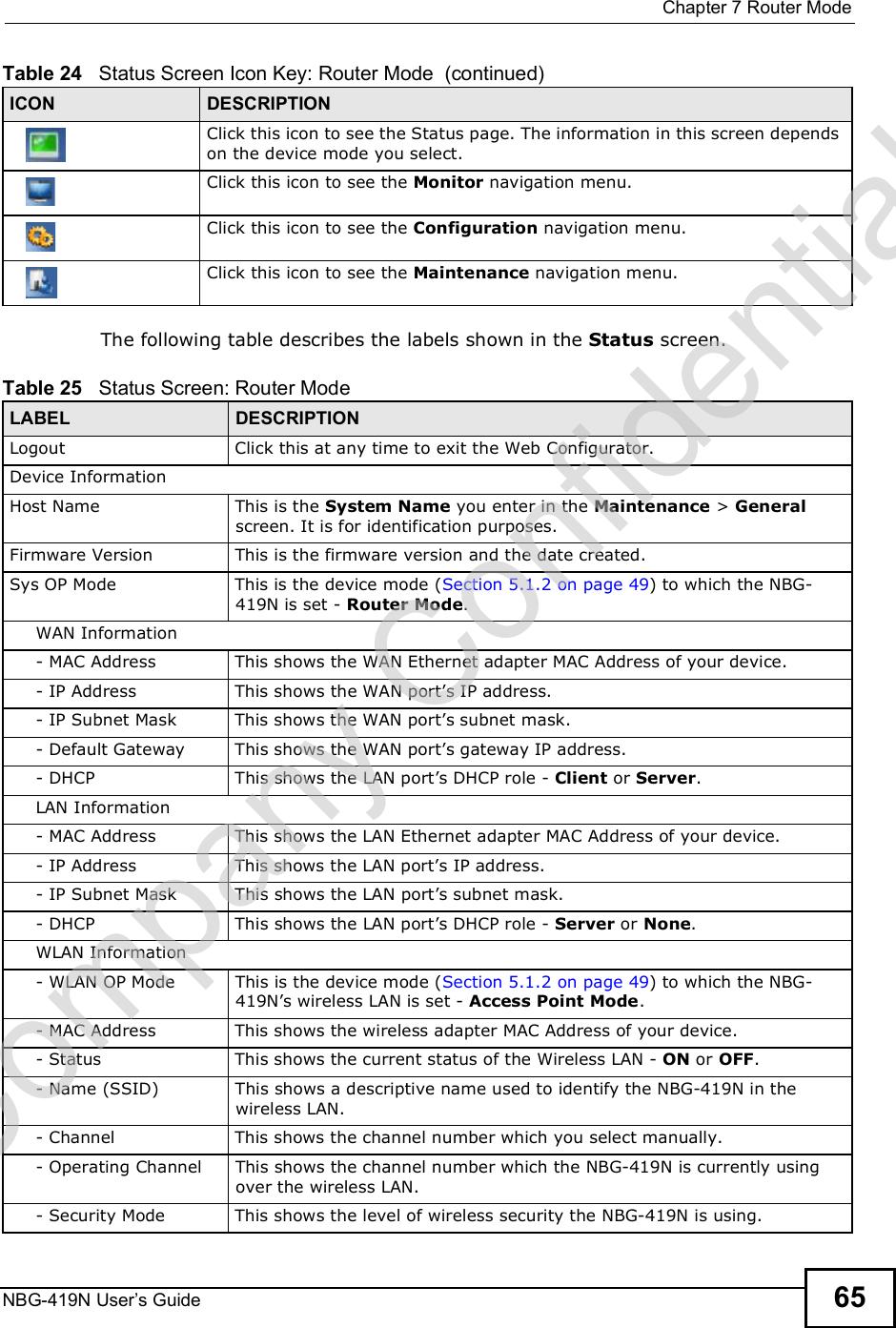

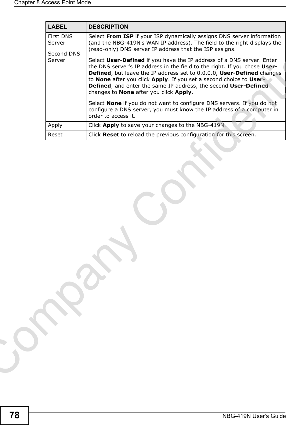


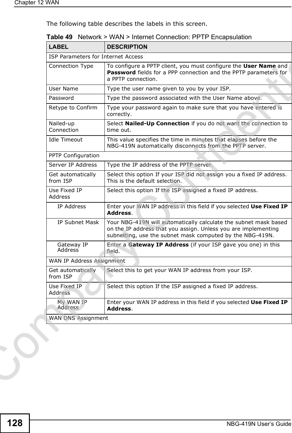


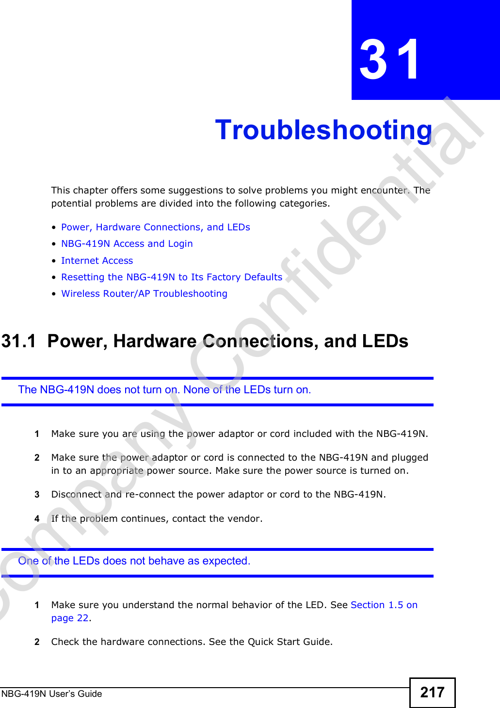
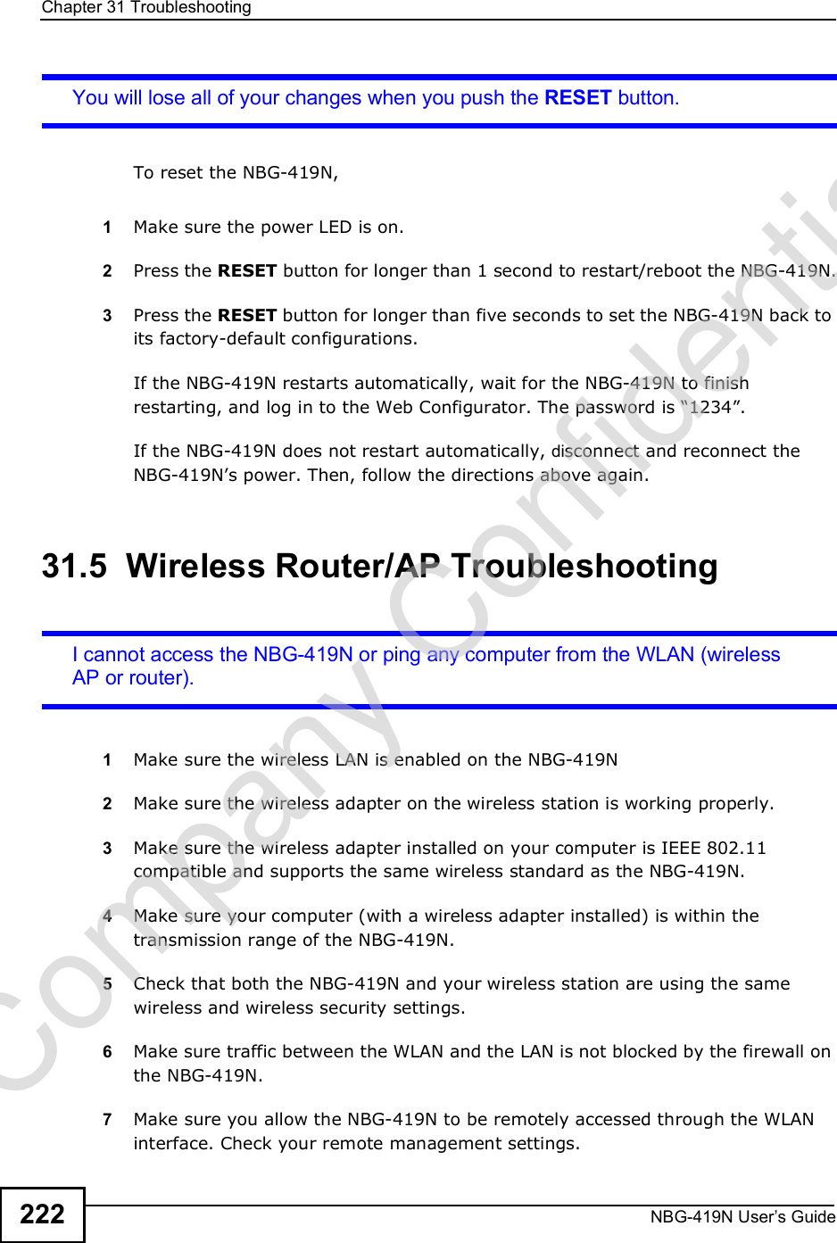
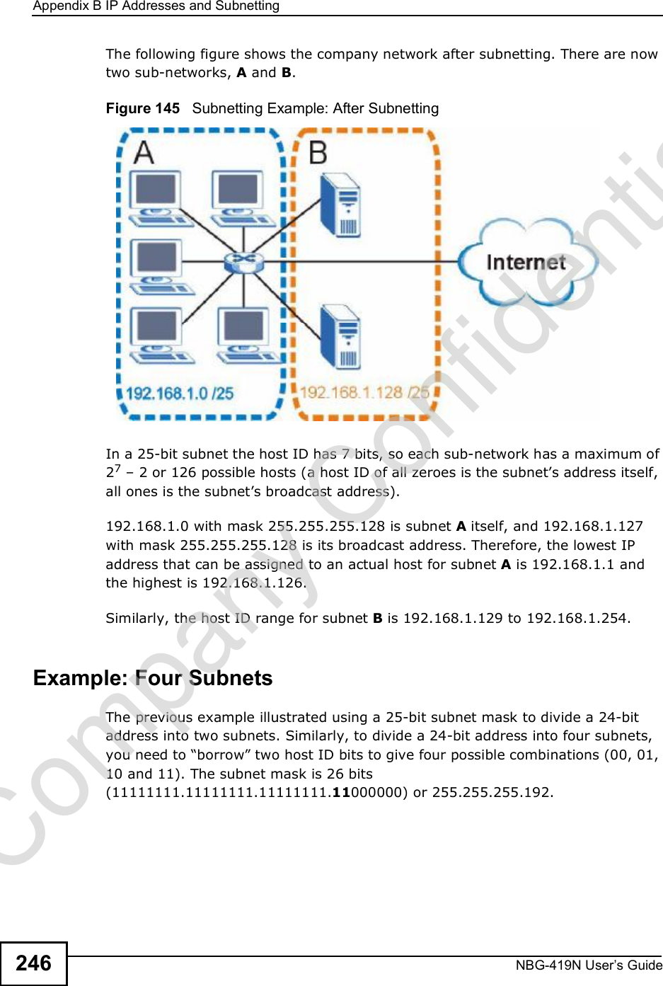
![Chapter 31TroubleshootingNBG-419N User s Guide 2192If this does not work, you have to reset the device to its factory defaults. See Section 31.4 on page 221.I cannot see or access the Login screen in the Web Configurator.1Make sure you are using the correct IP address. The default IP address is 192.168.1.1. If you changed the IP address (Section 13.4 on page 137), use the new IP address. If you changed the IP address and have forgotten it, see the troubleshooting suggestions for I don!t know the IP address of my NBG-419N.2Check the hardware connections, and make sure the LEDs are behaving as expected. See the Quick Start Guide. 3Make sure your Internet browser does not block pop-up windows and has JavaScripts and Java enabled. See Appendix A on page 233.4Make sure your computer is in the same subnet as the NBG-419N. (If you know that there are routers between your computer and the NBG-419N, skip this step.) If there is a DHCP server on your network, make sure your computer is using a dynamic IP address. See Section 14.3 on page 139. If there is no DHCP server on your network, make sure your computer!s IP address is in the same subnet as the NBG-419N. See Appendix B on page 241.5Reset the device to its factory defaults, and try to access the NBG-419N with the default IP address. See Section 28.3 on page 208.6If the problem continues, contact the network administrator or vendor, or try one of the advanced suggestions.Advanced Suggestion If your computer is connected to the WAN port or is connected wirelessly, use a computer that is connected to a LAN/ETHERNET port.I can see the Login screen, but I cannot log in to the NBG-419N.1Make sure you have entered the password correctly. The default password is 1234. This field is case-sensitive, so make sure [Caps Lock] is not on. Company Confidential](https://usermanual.wiki/ZyXEL-Communications/NBG419N/User-Guide-1180986-Page-219.png)
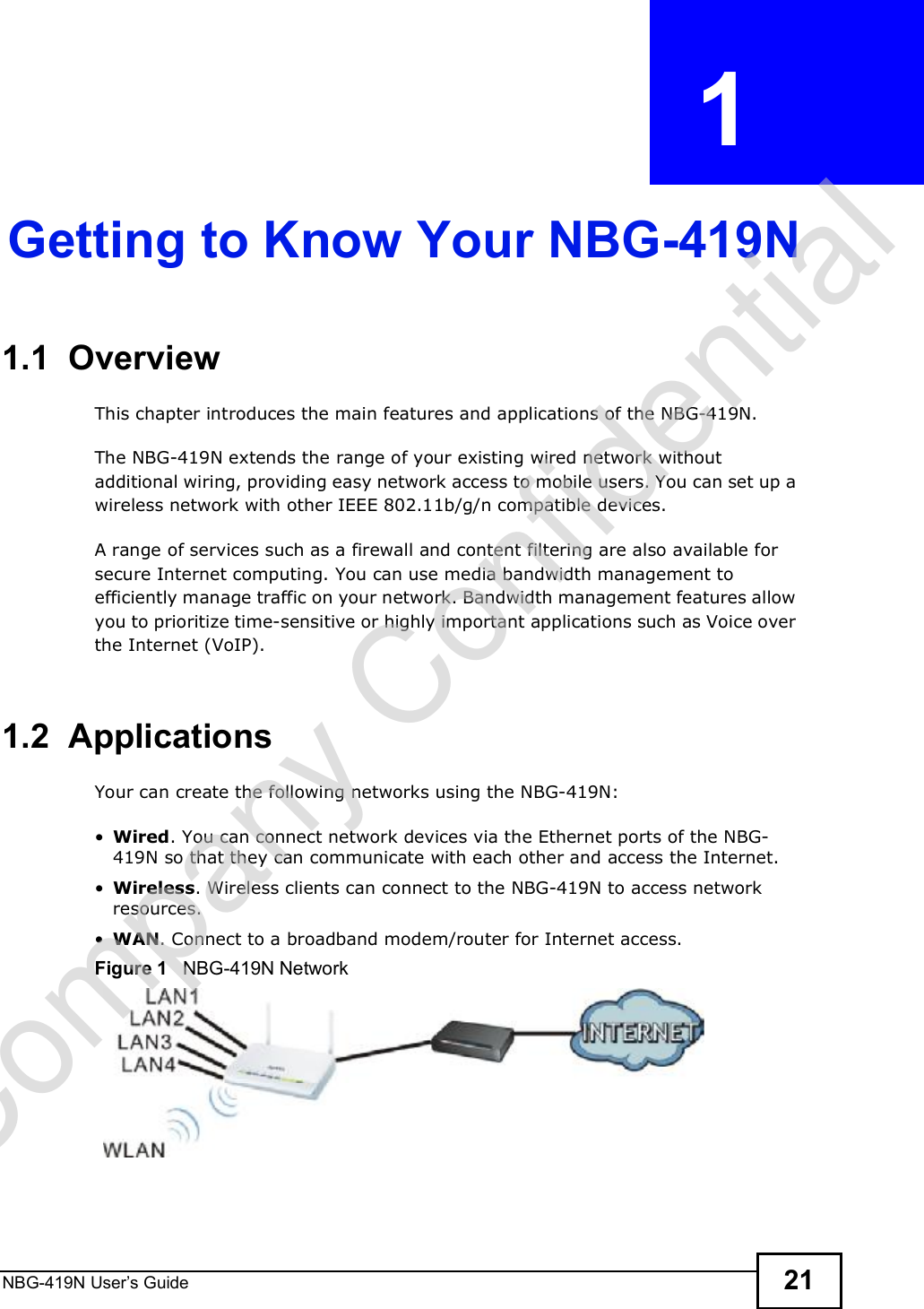
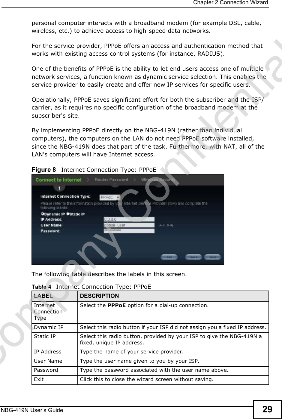
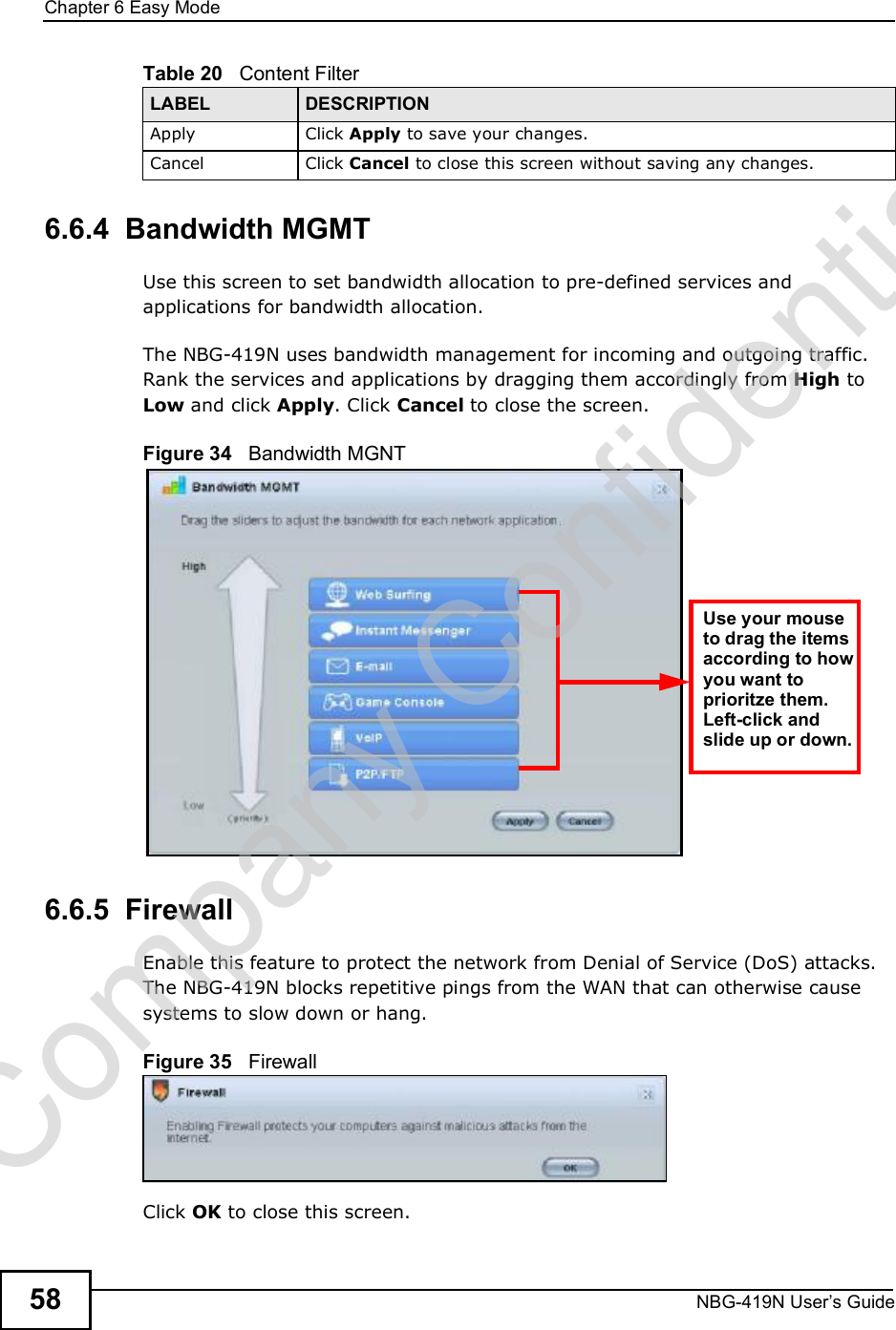
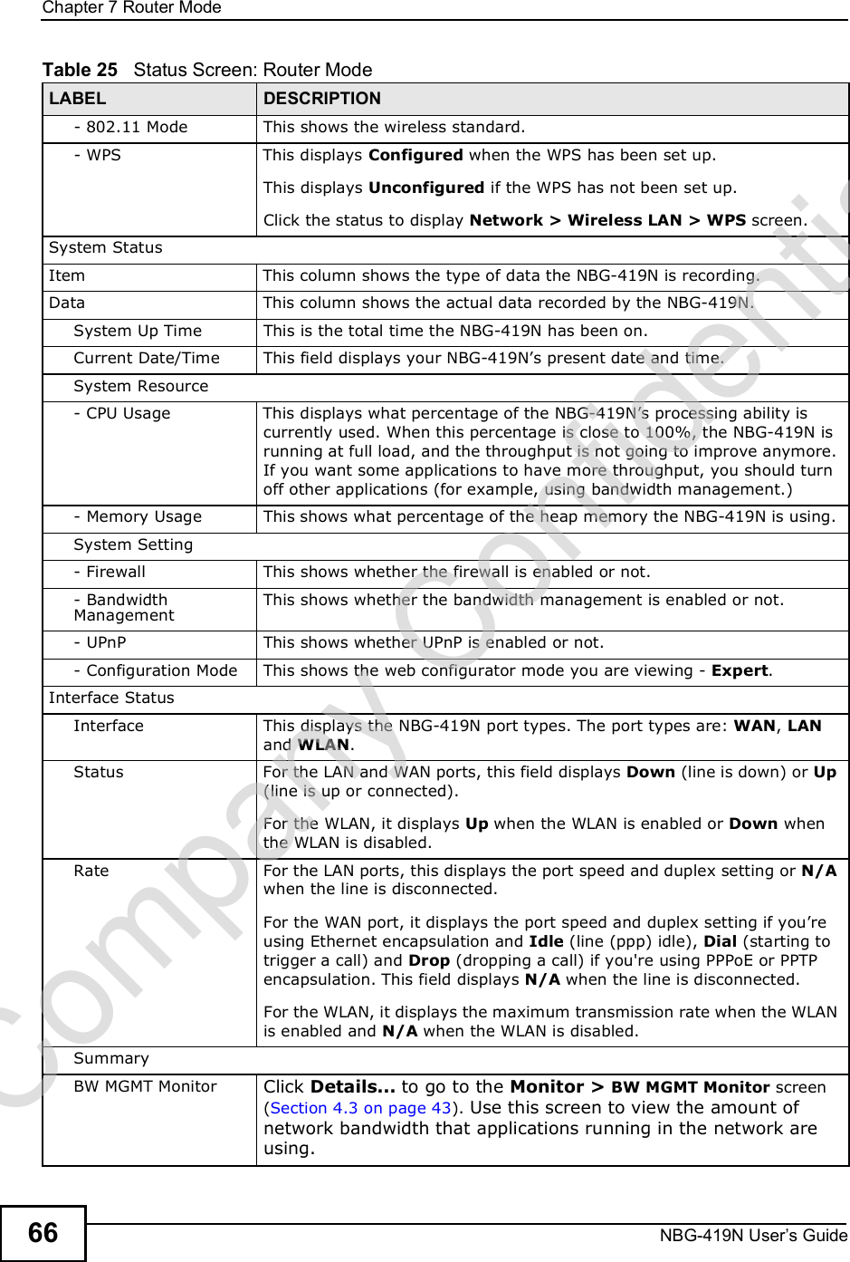
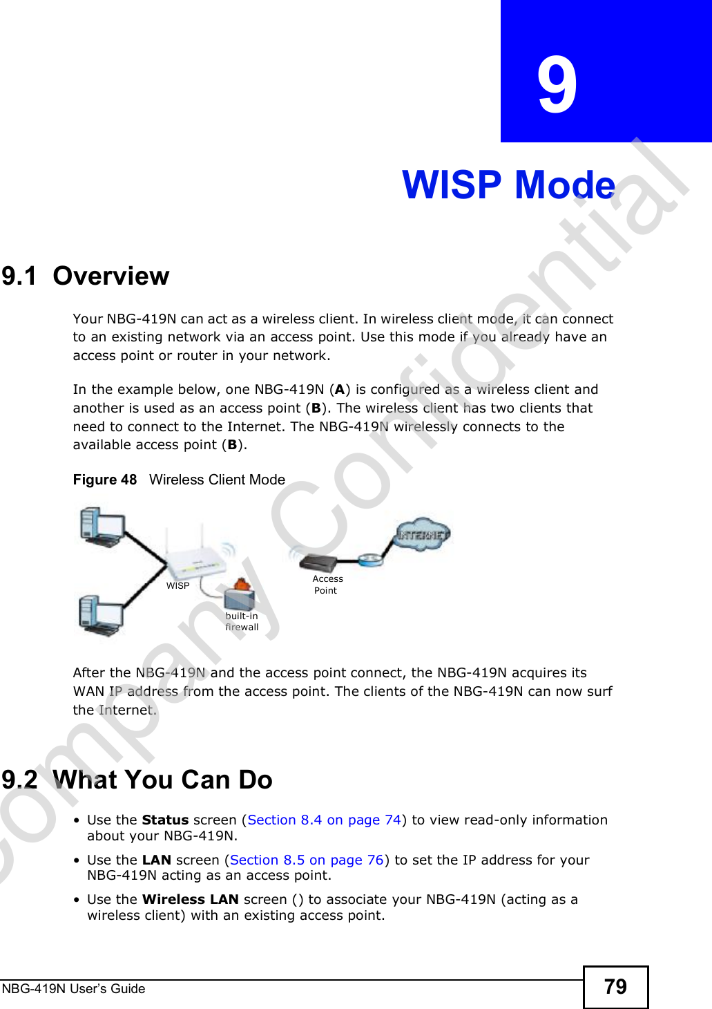
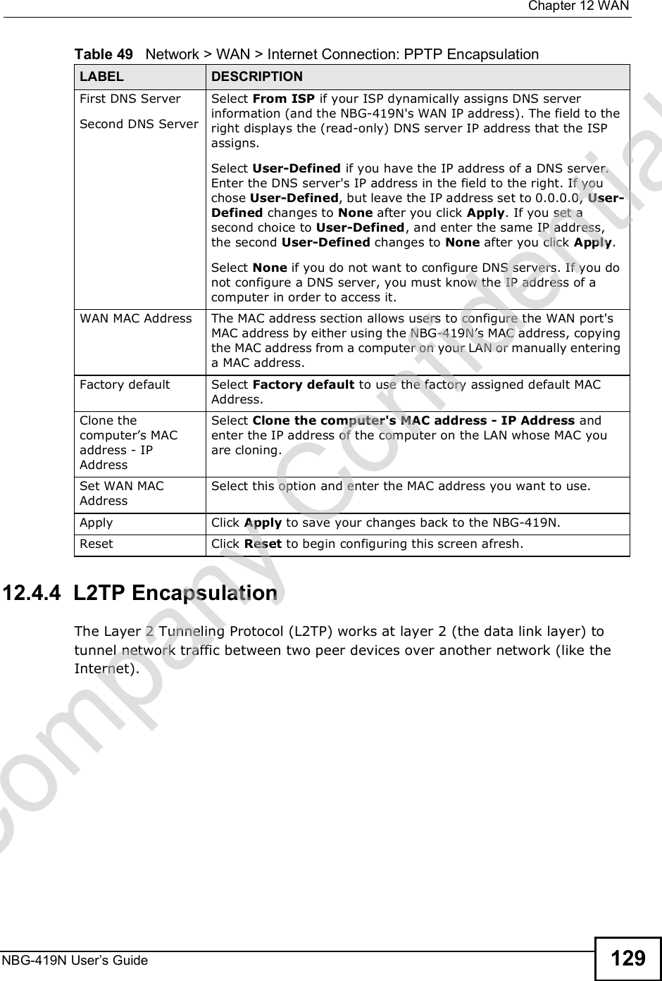
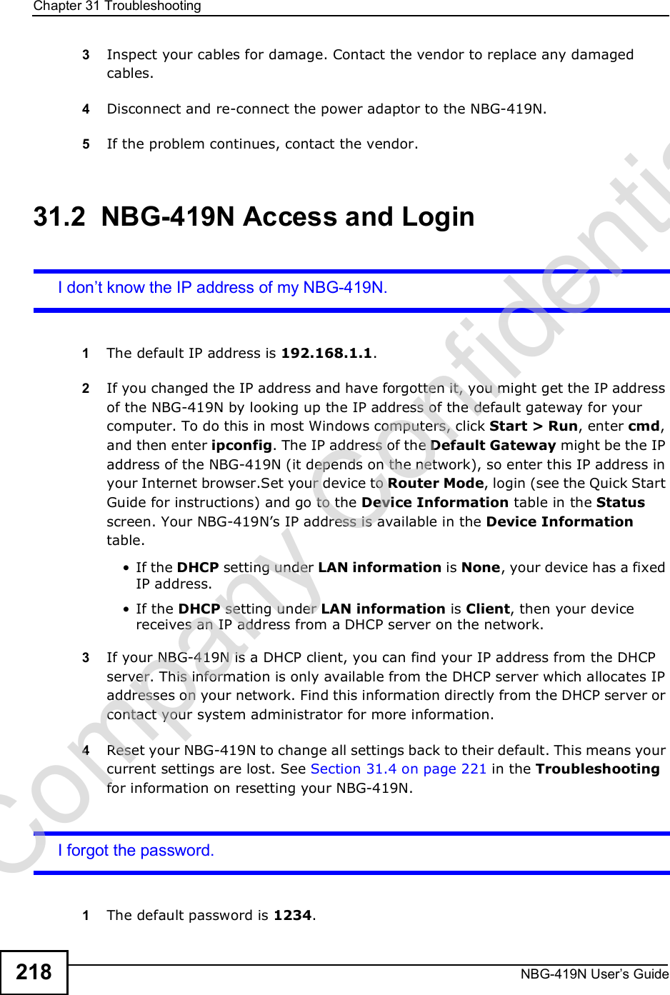
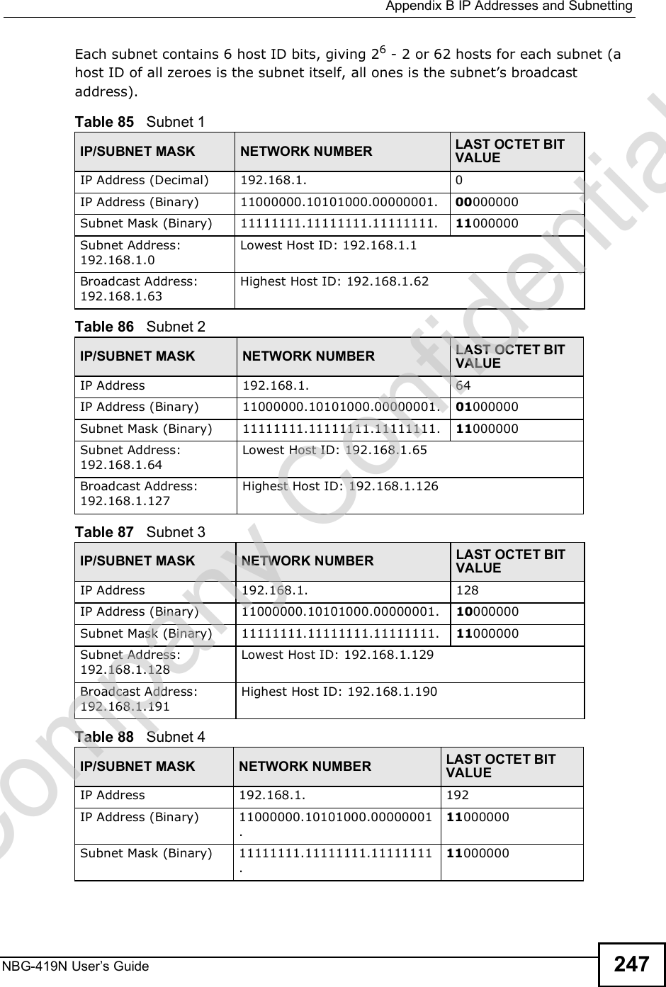
![Chapter 31TroubleshootingNBG-419N User s Guide2202This can happen when you fail to log out properly from your last session. Try logging in again after 5 minutes.3Disconnect and re-connect the power adaptor or cord to the NBG-419N. 4If this does not work, you have to reset the device to its factory defaults. See Section 31.4 on page 221.31.3 Internet AccessI cannot access the Internet.1Check the hardware connections, and make sure the LEDs are behaving as expected. See the Quick Start Guide.2Make sure you entered your ISP account information correctly in the wizard. These fields are case-sensitive, so make sure [Caps Lock] is not on.3If you are trying to access the Internet wirelessly, make sure the wireless settings in the wireless client are the same as the settings in the AP. Go to Network > Wireless LAN > General > WDS and check if the NBG-419N is set to bridge mode. Select Disable and try to connect to the Internet again.4Disconnect all the cables from your device, and follow the directions in the Quick Start Guide again. 5Go to Maintenance > Sys OP Mode > General. Check your System Operation Mode setting. Select Router if your device routes traffic between a local network and another network such as the Internet. Select Access Point if your device bridges traffic between clients on the same network. 6If the problem continues, contact your ISP.I cannot access the Internet anymore. I had access to the Internet (with the NBG-419N), but my Internet connection is not available anymore.Company Confidential](https://usermanual.wiki/ZyXEL-Communications/NBG419N/User-Guide-1180986-Page-220.png)
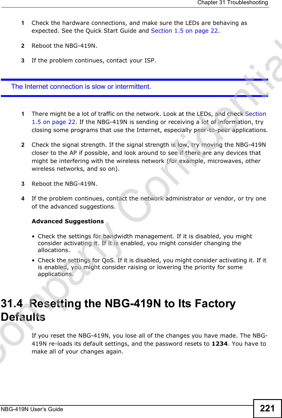


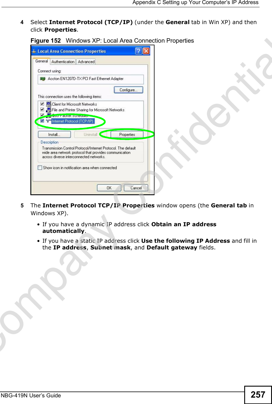
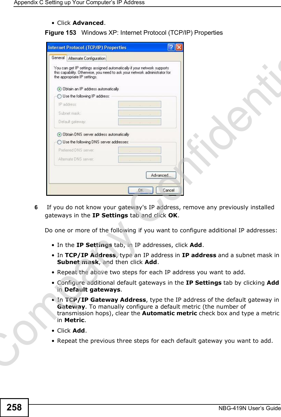
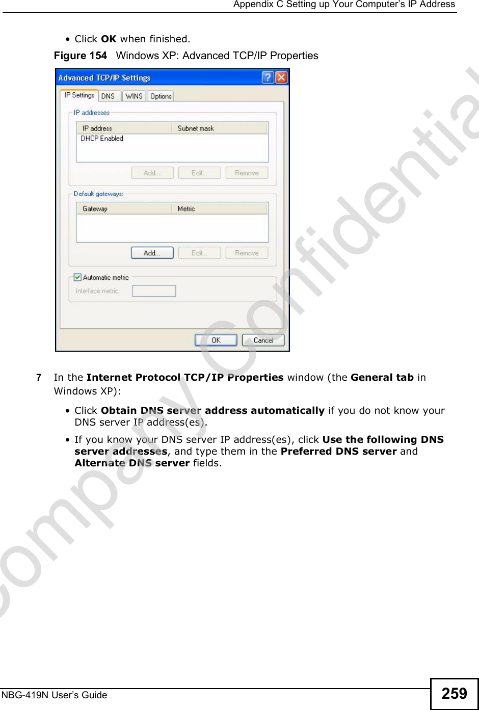
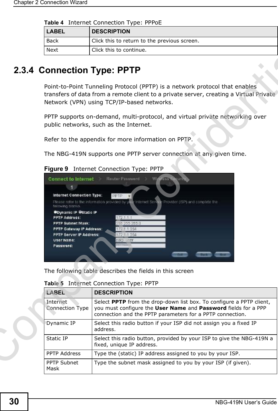
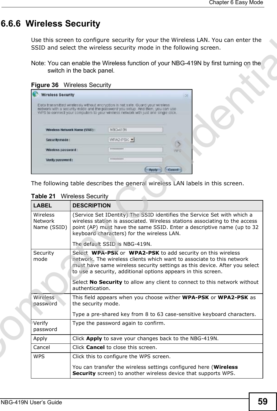
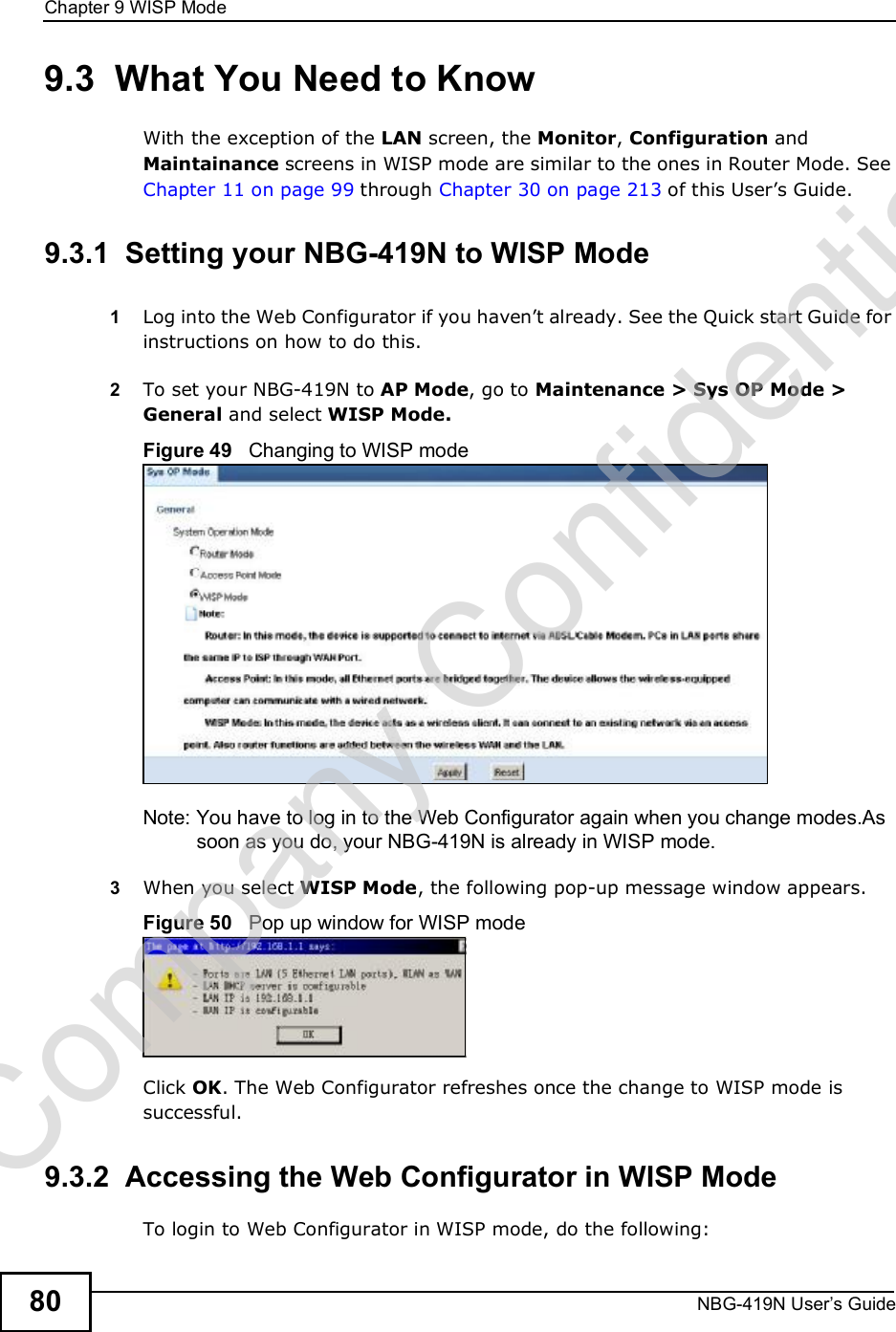
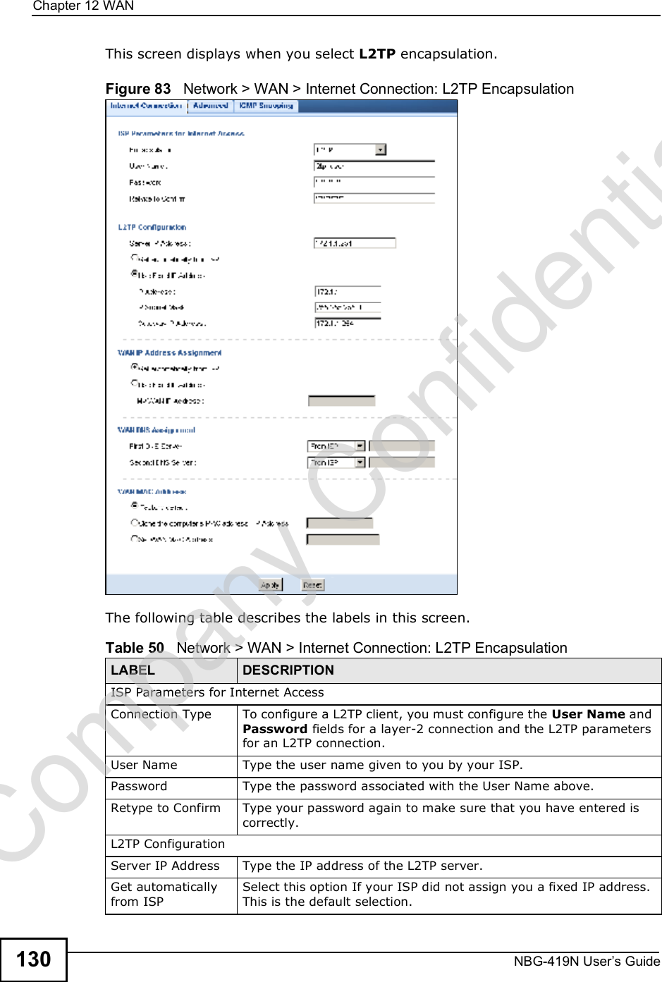
![Appendix CSetting up Your Computer s IP AddressNBG-419N User s Guide260If you have previously configured DNS servers, click Advanced and then the DNS tab to order them.Figure 155 Windows XP: Internet Protocol (TCP/IP) Properties8Click OK to close the Internet Protocol (TCP/IP) Properties window.9Click Close (OK in Windows 2000/NT) to close the Local Area Connection Properties window.10 Close the Network Connections window (Network and Dial-up Connections in Windows 2000/NT).11 Turn on your Prestige and restart your computer (if prompted).Verifying Settings1Click Start, All Programs, Accessories and then Command Prompt.2In the Command Prompt window, type "ipconfig" and then press [ENTER]. You can also open Network Connections, right-click a network connection, click Status and then click the Support tab.Company Confidential](https://usermanual.wiki/ZyXEL-Communications/NBG419N/User-Guide-1180986-Page-260.png)
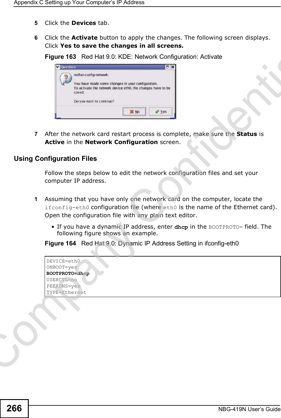
![Appendix CSetting up Your Computer s IP AddressNBG-419N User s Guide 267 If you have a static IP address, enter static in the BOOTPROTO= field. Type IPADDR= followed by the IP address (in dotted decimal notation) and type NETMASK= followed by the subnet mask. The following example shows an example where the static IP address is 192.168.1.10 and the subnet mask is 255.255.255.0. Figure 165 Red Hat 9.0: Static IP Address Setting in ifconfig-eth0 2If you know your DNS server IP address(es), enter the DNS server information in the resolv.conf file in the /etc directory. The following figure shows an example where two DNS server IP addresses are specified.Figure 166 Red Hat 9.0: DNS Settings in resolv.conf 3After you edit and save the configuration files, you must restart the network card. Enter./network restart in the /etc/rc.d/init.d directory. The following figure shows an example.Figure 167 Red Hat 9.0: Restart Ethernet Card DEVICE=eth0ONBOOT=yesBOOTPROTO=staticIPADDR=192.168.1.10NETMASK=255.255.255.0USERCTL=noPEERDNS=yesTYPE=Ethernetnameserver 172.23.5.1nameserver 172.23.5.2[root@localhost init.d]# network restartShutting down interface eth0: [OK]Shutting down loopback interface: [OK]Setting network parameters: [OK]Bringing up loopback interface: [OK]Bringing up interface eth0: [OK]Company Confidential](https://usermanual.wiki/ZyXEL-Communications/NBG419N/User-Guide-1180986-Page-267.png)
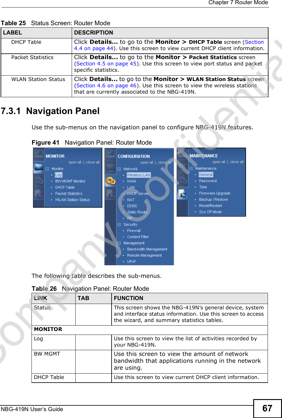
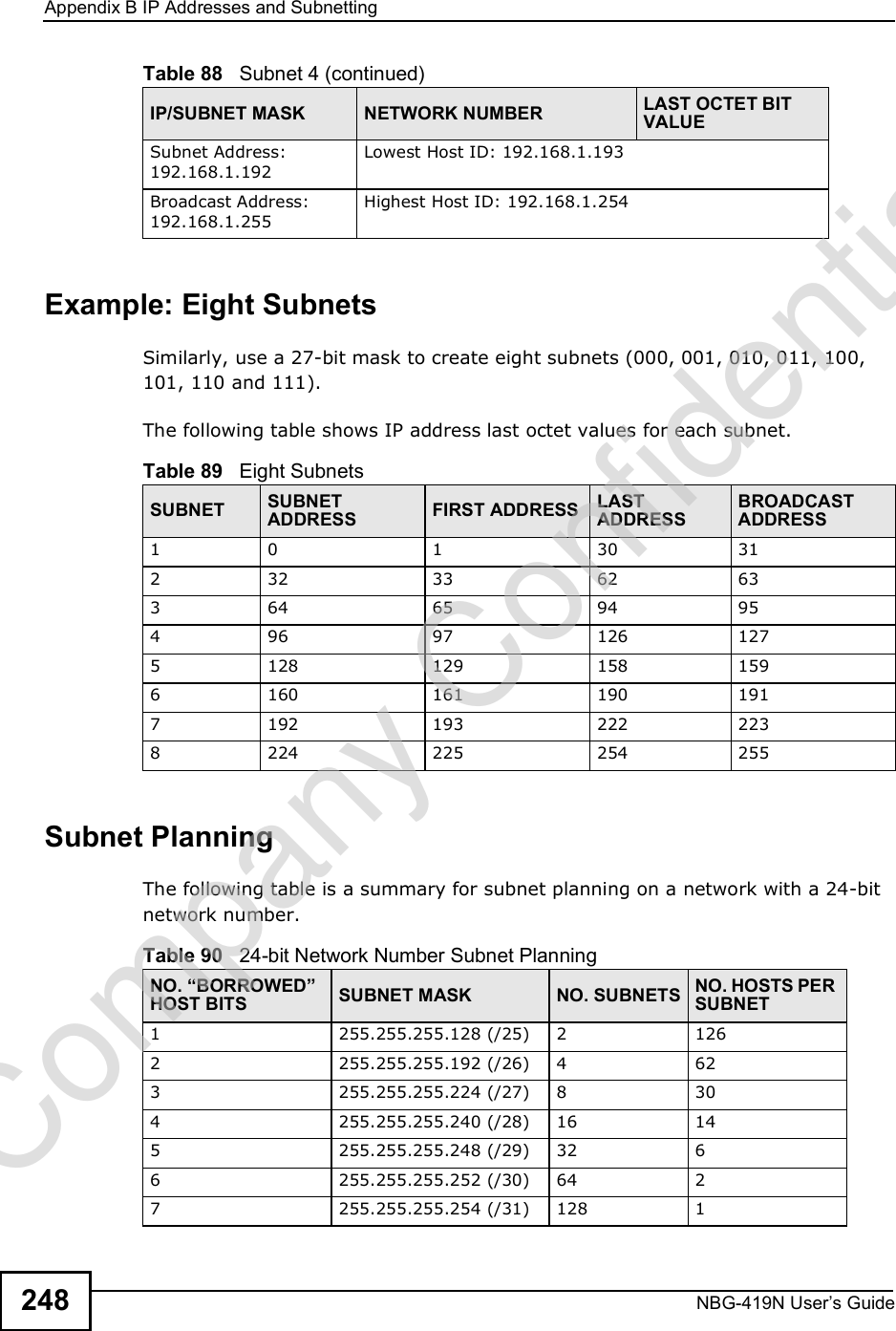
![Appendix CSetting up Your Computer s IP AddressNBG-419N User s Guide26832.1.1 Verifying SettingsEnter ifconfig in a terminal screen to check your TCP/IP properties. Figure 168 Red Hat 9.0: Checking TCP/IP Properties [root@localhost]# ifconfig eth0 Link encap:Ethernet HWaddr 00:50:BA:72:5B:44 inet addr:172.23.19.129 Bcast:172.23.19.255 Mask:255.255.255.0 UP BROADCAST RUNNING MULTICAST MTU:1500 Metric:1 RX packets:717 errors:0 dropped:0 overruns:0 frame:0 TX packets:13 errors:0 dropped:0 overruns:0 carrier:0 collisions:0 txqueuelen:100 RX bytes:730412 (713.2 Kb) TX bytes:1570 (1.5 Kb) Interrupt:10 Base address:0x1000 [root@localhost]#Company Confidential](https://usermanual.wiki/ZyXEL-Communications/NBG419N/User-Guide-1180986-Page-268.png)