ZyXEL Communications NBG5615 Simultaneous Dual-Band Wireless N750 Media Router User Manual Manual 1
ZyXEL Communications Corporation Simultaneous Dual-Band Wireless N750 Media Router Manual 1
Contents
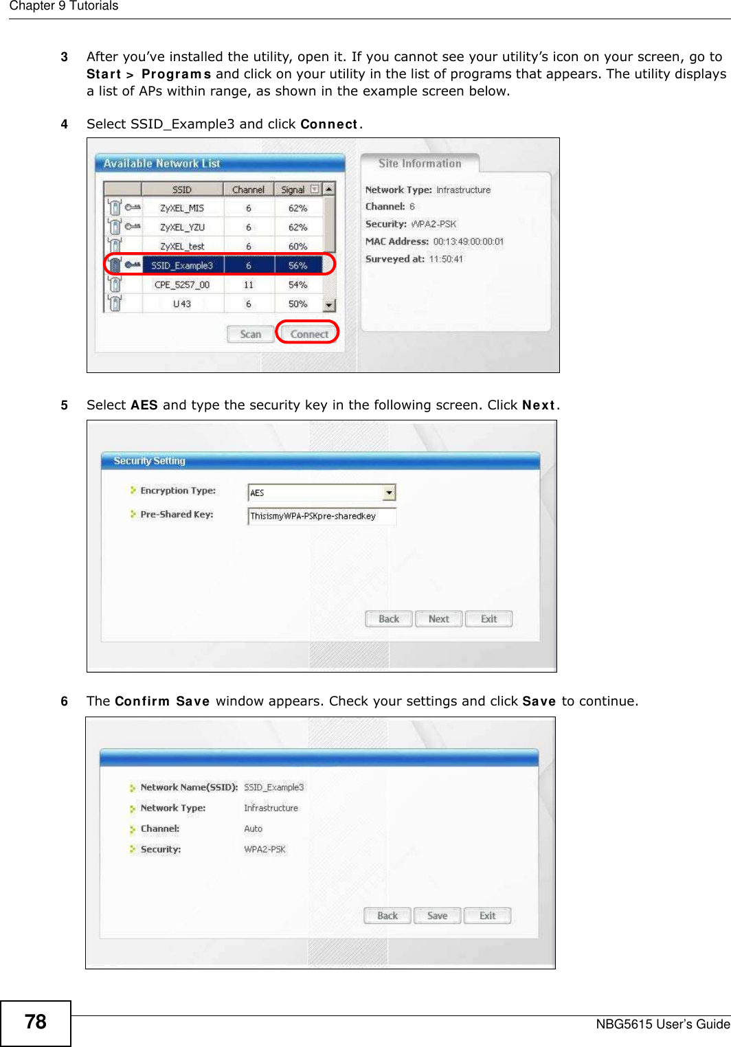
- 1. Manual-1
- 2. Manual-2
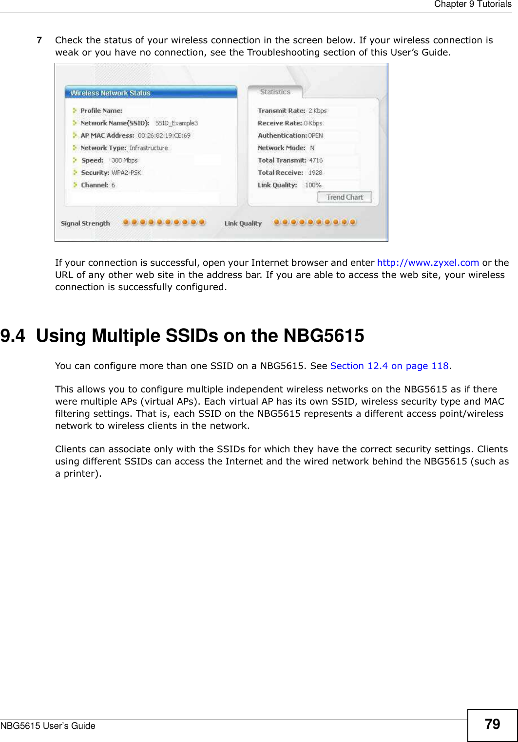
- 3. Manual-2(1020418)
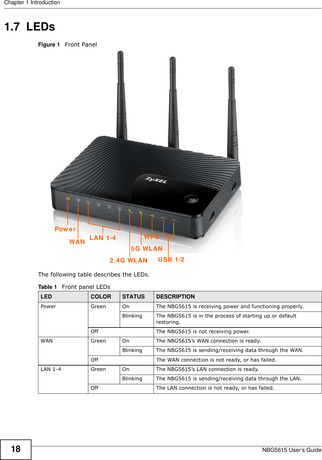
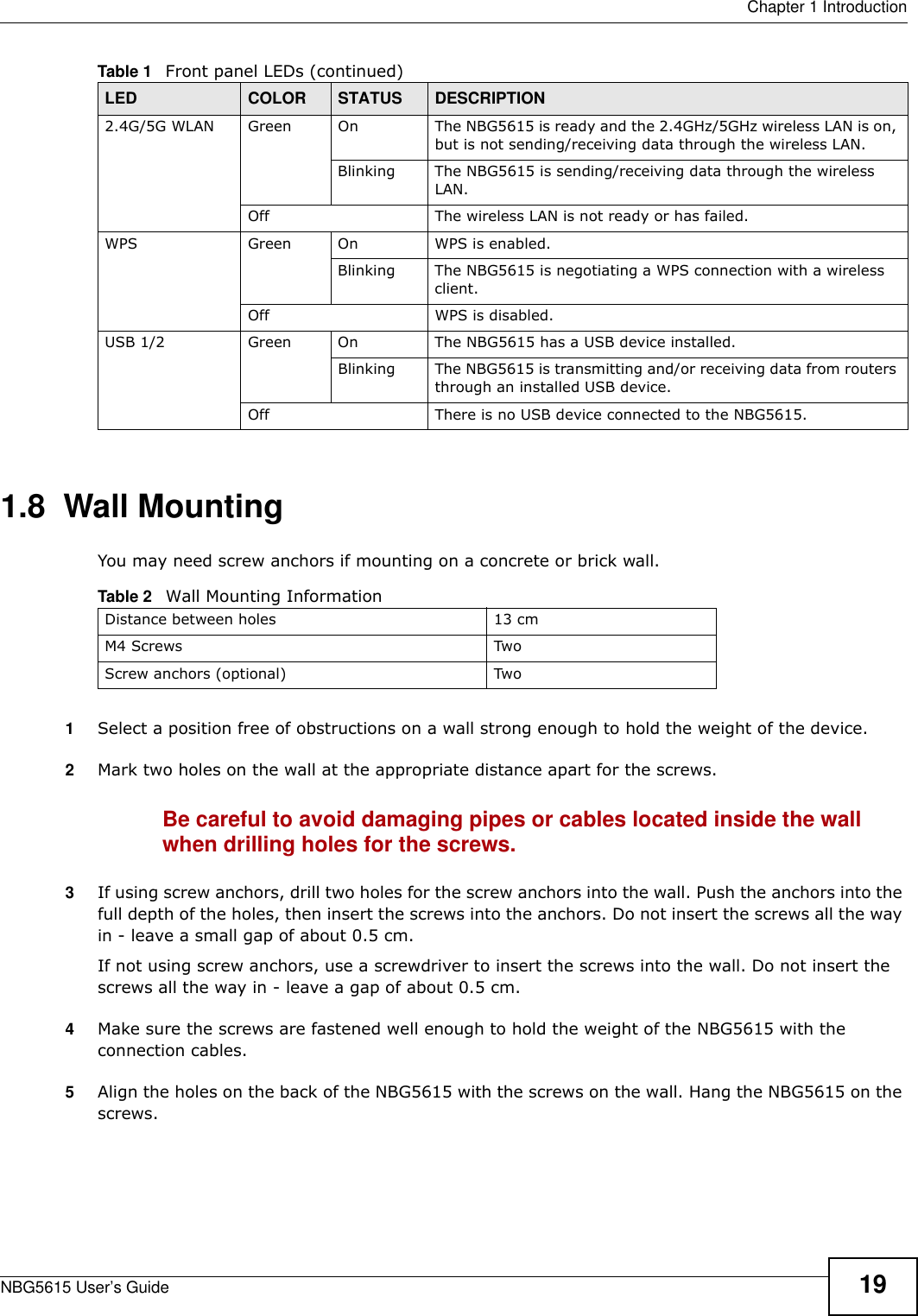
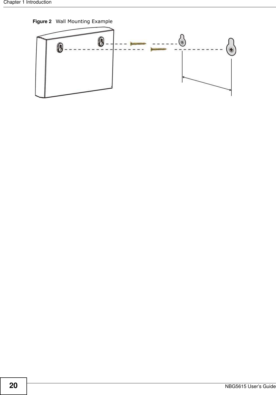
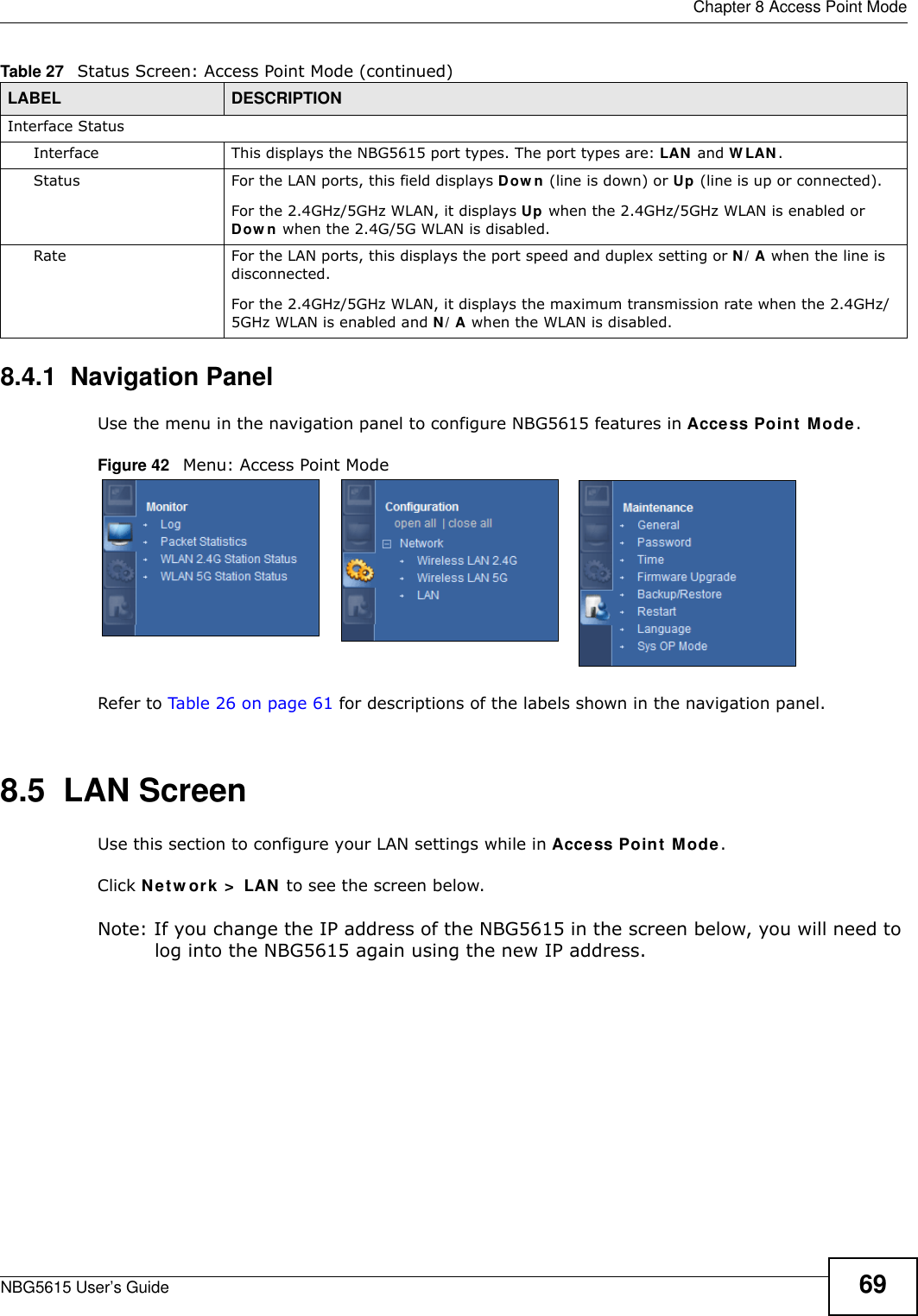
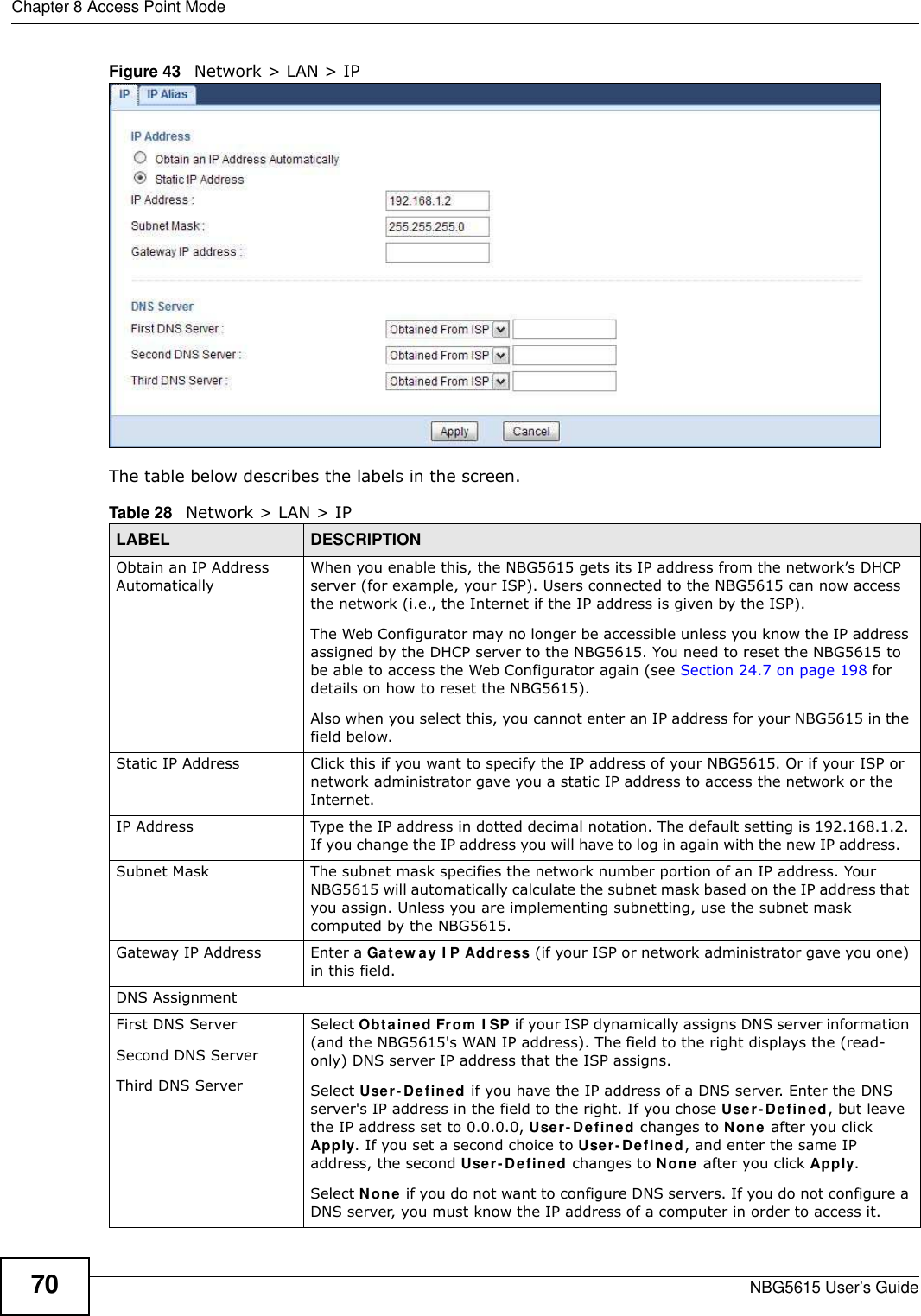
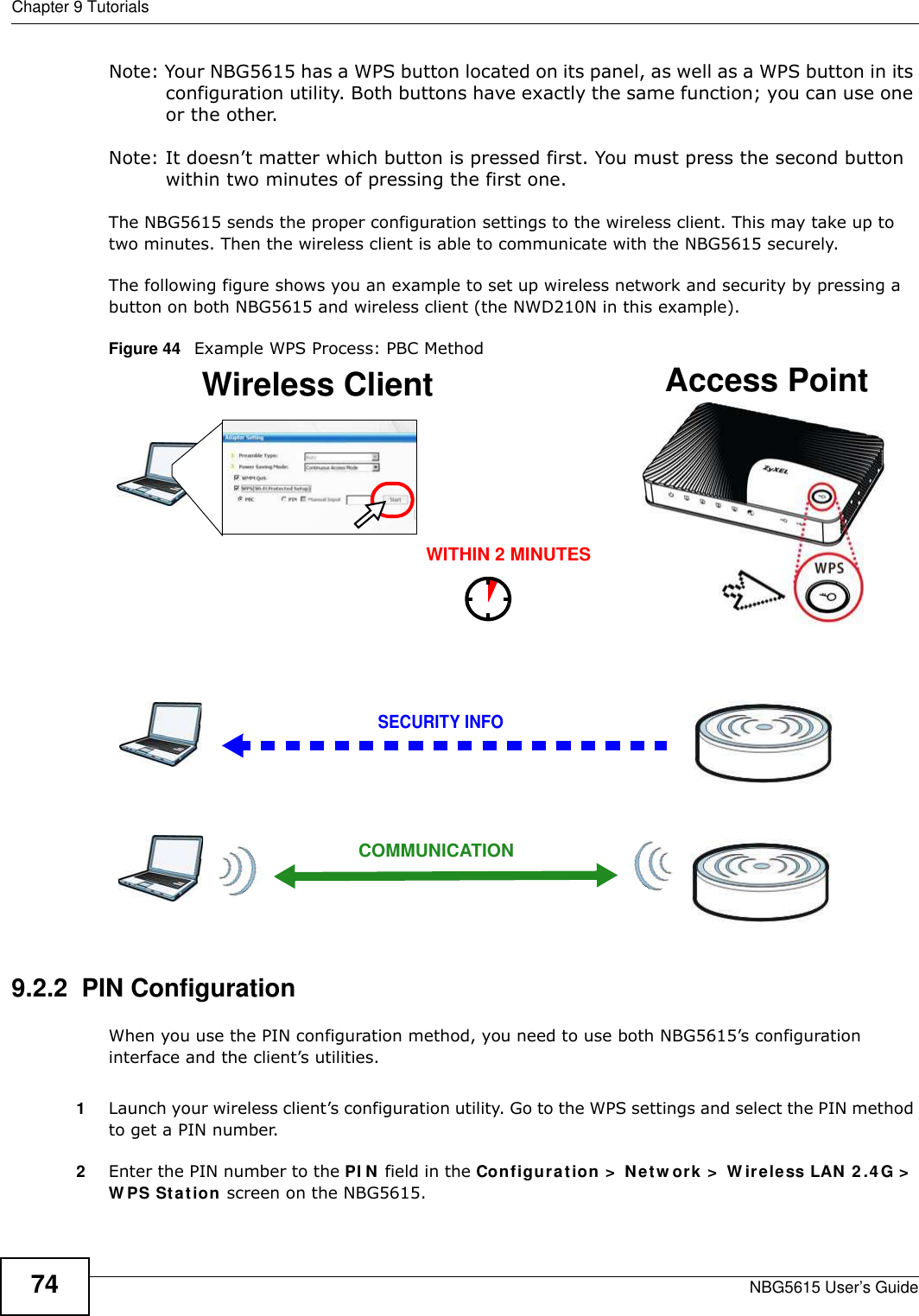
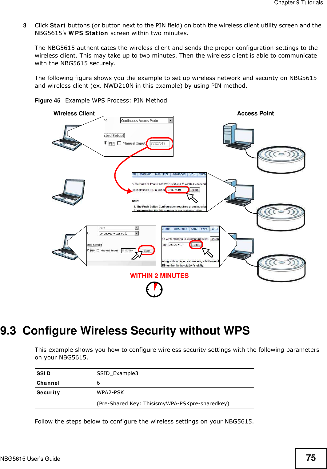
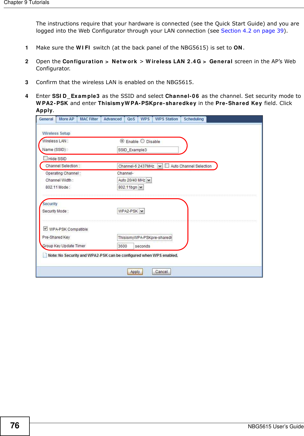
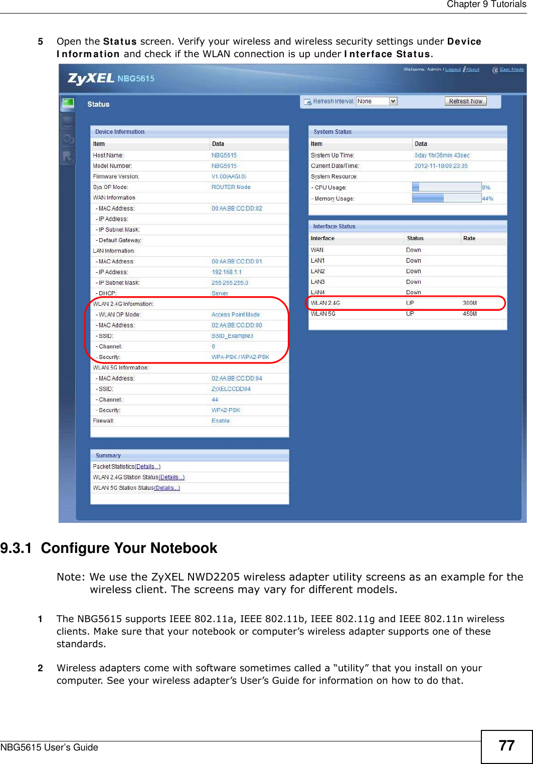
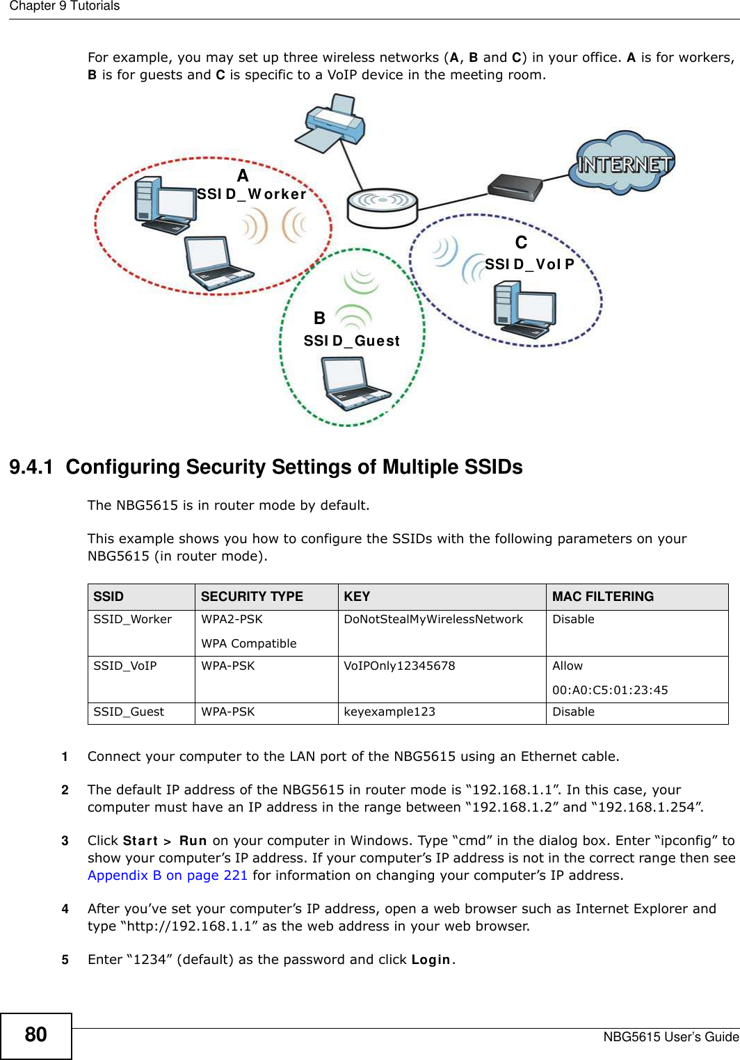
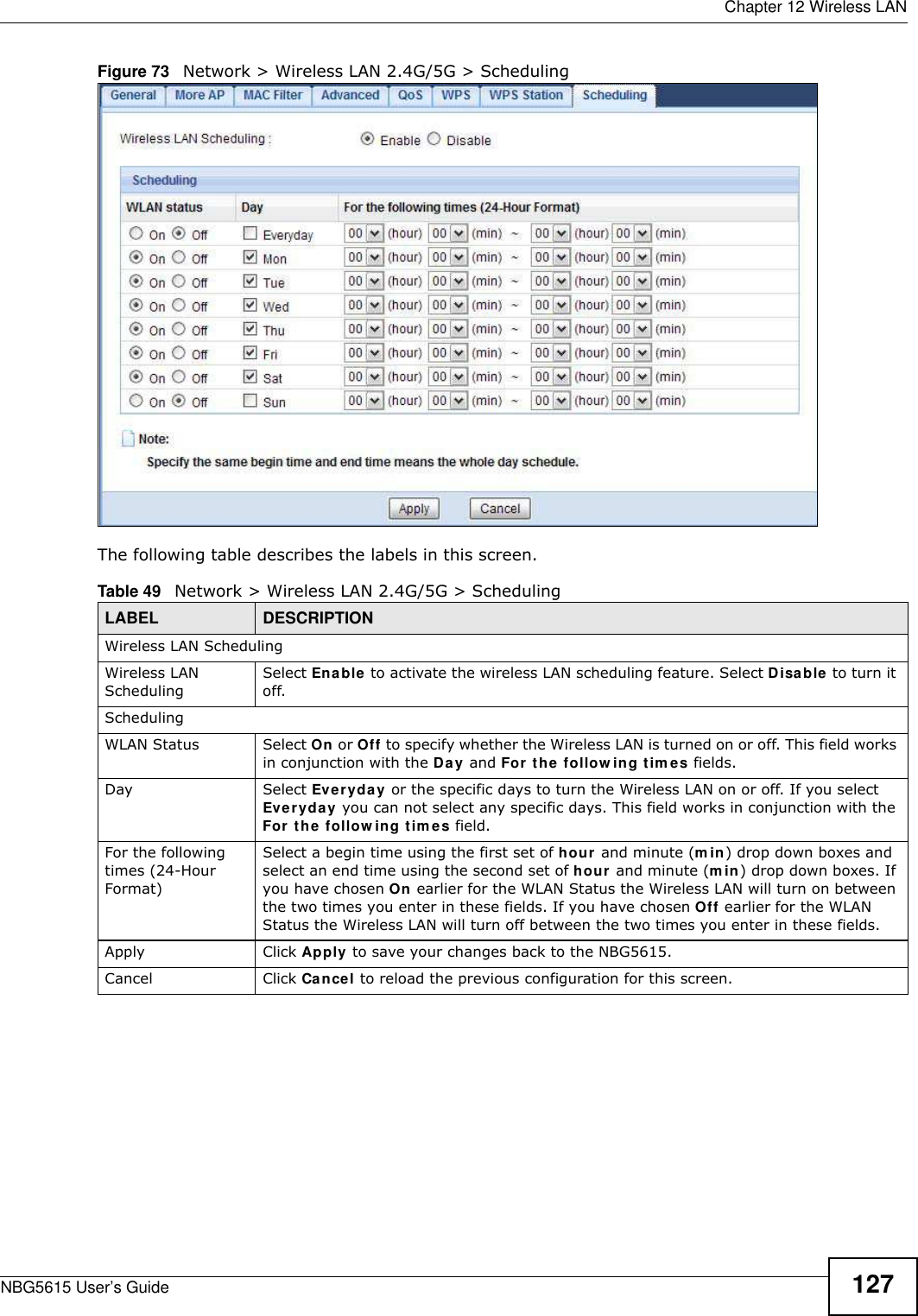
Manual-1