ZyXEL Communications NBG5615 Simultaneous Dual-Band Wireless N750 Media Router User Manual Manual 1
ZyXEL Communications Corporation Simultaneous Dual-Band Wireless N750 Media Router Manual 1
Contents
- 1. Manual-1
- 2. Manual-2
- 3. Manual-2(1020418)
Manual-1

Quick Start Guide
www.zyxel.com
NBG561 5
Simultaneous Dual-Band Wireless N750 Media Router
Version 1.00
Edition 1, 12/2012
Copyright © 2012 ZyXEL Communications Corporation
User’s Guide
Default Login Details
LAN IP Address http://192.168.1.1
(Router Mode)
http://192.168.1.2
(Access Point Mode)
Password 1234

NBG5615 User’s Guide2
IMPORTANT!
READ CAREFULLY BEFORE USE.
KEEP THIS GUIDE FOR FUTURE REFERENCE.
Screenshots and graphics in this book may differ slightly from your product due to differences in
your product firmware or your computer operating system. Every effort has been made to ensure
that the information in this manual is accurate.
Related Documentation
•Quick Start Guide
The Quick Start Guide shows how to connect the NBG5615 and access the Web Configurator
wizards. It contains information on setting up your network and configuring for Internet access.

Contents Overview
NBG5615 User’s Guide 3
Contents Overview
User’s Guide .......................................................................................................................................13
Introduction .............................................................................................................................................15
ZyXEL NetUSB Share Center Utility .......................................................................................................21
Connection Wizard ..................................................................................................................................27
Introducing the Web Configurator ...........................................................................................................39
NBG5615 Modes .....................................................................................................................................43
Easy Mode ..............................................................................................................................................45
Router Mode ...........................................................................................................................................57
Access Point Mode .................................................................................................................................65
Tutorials ..................................................................................................................................................73
Technical Reference ..........................................................................................................................87
Monitor ....................................................................................................................................................89
WAN ........................................................................................................................................................95
Wireless LAN ........................................................................................................................................105
LAN .......................................................................................................................................................129
DHCP Server ........................................................................................................................................133
NAT .......................................................................................................................................................139
DDNS ....................................................................................................................................................149
Static Route ...........................................................................................................................................151
Firewall ..................................................................................................................................................155
Content Filtering ....................................................................................................................................161
Bandwidth Management .......................................................................................................................165
Remote Management ............................................................................................................................173
Universal Plug-and-Play (UPnP) ...........................................................................................................177
USB Media Sharing ...............................................................................................................................183
Maintenance ..........................................................................................................................................193
Troubleshooting ....................................................................................................................................203

Contents Overview
NBG5615 User’s Guide
4

Table of Contents
NBG5615 User’s Guide 5
Table of Contents
Contents Overview ..............................................................................................................................3
Table of Contents .................................................................................................................................5
Part I: User’s Guide ......................................................................................... 13
Chapter 1
Introduction.........................................................................................................................................15
1.1 Overview ...........................................................................................................................................15
1.2 Applications .......................................................................................................................................15
1.3 Ways to Manage the NBG5615 ........................................................................................................16
1.4 Good Habits for Managing the NBG5615 .........................................................................................16
1.5 Resetting the NBG5615 ....................................................................................................................16
1.5.1 How to Use the RESET Button ................................................................................................16
1.6 The WPS Button ...............................................................................................................................16
1.7 LEDs .................................................................................................................................................18
1.8 Wall Mounting ...................................................................................................................................19
Chapter 2
ZyXEL NetUSB Share Center Utility..................................................................................................21
2.1 Overview ...........................................................................................................................................21
2.1.1 Quick Setup .............................................................................................................................21
2.1.2 Installing ZyXEL NetUSB Share Center Utility .........................................................................21
2.2 The ZyXEL NetUSB Share Center Utility ..........................................................................................22
2.2.1 The Menus ...............................................................................................................................23
2.2.2 The ZyXEL NetUSB Share Center Configuration Window ......................................................24
2.2.3 The Auto-Connect Printer List Window ...................................................................................25
2.2.4 Exit the ZyXEL NetUSB Share Center Utility ...........................................................................26
Chapter 3
Connection Wizard .............................................................................................................................27
3.1 Overview ...........................................................................................................................................27
3.2 Accessing the Wizard ........................................................................................................................27
3.3 Connect to Internet ............................................................................................................................28
3.3.1 Connection Type: IPoE ............................................................................................................29
3.3.2 Connection Type: PPPoE ........................................................................................................30
3.3.3 Connection Type: PPTP ..........................................................................................................32
3.4 Router Password ...............................................................................................................................33

Table of Contents
NBG5615 User’s Guide
6
3.5 Wireless Security ..............................................................................................................................34
3.5.1 Wireless Security: No Security ................................................................................................34
3.5.2 Wireless Security: WPA2-PSK .................................................................................................35
Chapter 4
Introducing the Web Configurator ....................................................................................................39
4.1 Overview ...........................................................................................................................................39
4.2 Accessing the Web Configurator .......................................................................................................39
4.2.1 Login Screen ...........................................................................................................................39
4.2.2 Password Screen ....................................................................................................................40
Chapter 5
NBG5615 Modes .................................................................................................................................43
5.1 Overview ...........................................................................................................................................43
5.1.1 Web Configurator Modes .........................................................................................................43
5.1.2 Device Modes ..........................................................................................................................43
Chapter 6
Easy Mode...........................................................................................................................................45
6.1 Overview ...........................................................................................................................................45
6.2 What You Can Do .............................................................................................................................46
6.3 What You Need to Know ...................................................................................................................46
6.4 Navigation Panel ...............................................................................................................................46
6.5 Network Map .....................................................................................................................................47
6.6 Control Panel ....................................................................................................................................48
6.6.1 Game Engine ...........................................................................................................................49
6.6.2 Power Saving ..........................................................................................................................49
6.6.3 Content Filter ...........................................................................................................................50
6.6.4 Bandwidth MGMT ....................................................................................................................51
6.6.5 Firewall ....................................................................................................................................52
6.6.6 Wireless Security .....................................................................................................................52
6.6.7 WPS ........................................................................................................................................53
6.7 Status Screen in Easy Mode .............................................................................................................54
Chapter 7
Router Mode........................................................................................................................................57
7.1 Overview ...........................................................................................................................................57
7.2 Router Mode Status Screen ..............................................................................................................57
7.2.1 Navigation Panel .....................................................................................................................60
Chapter 8
Access Point Mode.............................................................................................................................65
8.1 Overview ...........................................................................................................................................65

Table of Contents
NBG5615 User’s Guide 7
8.2 What You Can Do .............................................................................................................................65
8.3 What You Need to Know ...................................................................................................................65
8.3.1 Setting your NBG5615 to AP Mode .........................................................................................66
8.3.2 Accessing the Web Configurator in Access Point Mode ..........................................................66
8.3.3 Configuring your WLAN and Maintenance Settings ................................................................67
8.4 AP Mode Status Screen ....................................................................................................................67
8.4.1 Navigation Panel .....................................................................................................................69
8.5 LAN Screen .......................................................................................................................................69
Chapter 9
Tutorials...............................................................................................................................................73
9.1 Overview ...........................................................................................................................................73
9.2 Set Up a Wireless Network with WPS ...............................................................................................73
9.2.1 Push Button Configuration (PBC) ............................................................................................73
9.2.2 PIN Configuration ....................................................................................................................74
9.3 Configure Wireless Security without WPS ........................................................................................75
9.3.1 Configure Your Notebook ........................................................................................................77
9.4 Using Multiple SSIDs on the NBG5615 .............................................................................................79
9.4.1 Configuring Security Settings of Multiple SSIDs ......................................................................80
9.5 Automatically Connecting to a USB Printer .......................................................................................84
Part II: Technical Reference............................................................................ 87
Chapter 10
Monitor.................................................................................................................................................89
10.1 Overview .........................................................................................................................................89
10.2 What You Can Do ...........................................................................................................................89
10.3 The Log Screen ...............................................................................................................................89
10.3.1 View Log ................................................................................................................................89
10.4 DHCP Table .................................................................................................................................90
10.5 Packet Statistics ...........................................................................................................................91
10.6 WLAN Station Status ...................................................................................................................92
Chapter 11
WAN .....................................................................................................................................................95
11.1 Overview .........................................................................................................................................95
11.2 What You Can Do ............................................................................................................................95
11.3 What You Need To Know .................................................................................................................95
11.3.1 Configuring Your Internet Connection ....................................................................................96
11.4 Internet Connection .........................................................................................................................97
11.4.1 IPoE Encapsulation ................................................................................................................97

Table of Contents
NBG5615 User’s Guide
8
11.4.2 PPPoE Encapsulation ............................................................................................................99
11.4.3 PPTP Encapsulation ............................................................................................................101
11.5 Advanced WAN Screen .................................................................................................................104
Chapter 12
Wireless LAN.....................................................................................................................................105
12.1 Overview .......................................................................................................................................105
12.1.1 What You Can Do ................................................................................................................106
12.1.2 What You Should Know .......................................................................................................106
12.2 General Wireless LAN Screen .....................................................................................................110
12.3 Wireless Security .......................................................................................................................... 112
12.3.1 No Security ..........................................................................................................................112
12.3.2 WEP Encryption ..................................................................................................................113
12.3.3 WPA-PSK/WPA2-PSK ......................................................................................................... 115
12.3.4 WPA/WPA2 .......................................................................................................................... 116
12.4 More AP Screen ............................................................................................................................ 118
12.4.1 More AP Edit .......................................................................................................................119
12.5 MAC Filter Screen ........................................................................................................................121
12.6 Wireless LAN Advanced Screen ...................................................................................................123
12.7 Quality of Service (QoS) Screen ...................................................................................................123
12.8 WPS Screen ..................................................................................................................................124
12.9 WPS Station Screen ......................................................................................................................126
12.10 Scheduling Screen ......................................................................................................................126
Chapter 13
LAN ....................................................................................................................................................129
13.1 Overview .......................................................................................................................................129
13.2 What You Can Do .........................................................................................................................129
13.3 What You Need To Know ..............................................................................................................129
13.3.1 IP Pool Setup .......................................................................................................................130
13.3.2 LAN TCP/IP .........................................................................................................................130
13.3.3 IP Alias ................................................................................................................................130
13.4 LAN IP Screen ..............................................................................................................................130
13.5 IP Alias Screen ..............................................................................................................................131
Chapter 14
DHCP Server .....................................................................................................................................133
14.1 Overview .......................................................................................................................................133
14.1.1 What You Can Do ................................................................................................................133
14.1.2 What You Need To Know .....................................................................................................133
14.2 DHCP Server General Screen ......................................................................................................133
14.3 DHCP Server Advanced Screen ................................................................................................134
14.4 DHCP Client List Screen ...............................................................................................................136

Table of Contents
NBG5615 User’s Guide 9
Chapter 15
NAT.....................................................................................................................................................139
15.1 Overview ....................................................................................................................................139
15.1.1 What You Can Do ................................................................................................................139
15.1.2 What You Need To Know .....................................................................................................140
15.2 General .........................................................................................................................................141
15.3 Port Forwarding Screen ...............................................................................................................142
15.3.1 Port Forwarding Edit Screen ..............................................................................................144
15.4 Port Trigger Screen .......................................................................................................................145
15.5 Technical Reference ......................................................................................................................146
15.5.1 NATPort Forwarding: Services and Port Numbers ..............................................................146
15.5.2 NAT Port Forwarding Example ............................................................................................146
15.5.3 Trigger Port Forwarding .......................................................................................................147
15.5.4 Trigger Port Forwarding Example ........................................................................................147
15.5.5 Two Points To Remember About Trigger Ports ...................................................................148
Chapter 16
DDNS..................................................................................................................................................149
16.1 Overview ......................................................................................................................................149
16.1.1 What You Need To Know .....................................................................................................149
16.2 General .......................................................................................................................................149
Chapter 17
Static Route.......................................................................................................................................151
17.1 Overview ....................................................................................................................................151
17.2 IP Static Route Screen .................................................................................................................151
17.2.1 Add/Edit Static Route ..........................................................................................................152
Chapter 18
Firewall ..............................................................................................................................................155
18.1 Overview .....................................................................................................................................155
18.1.1 What You Can Do ................................................................................................................155
18.1.2 What You Need To Know .....................................................................................................155
18.2 General Screen ............................................................................................................................157
18.3 Services Screen ............................................................................................................................157
Chapter 19
Content Filtering...............................................................................................................................161
19.1 Overview .......................................................................................................................................161
19.1.1 What You Need To Know .....................................................................................................161
19.2 Content Filter .................................................................................................................................161
19.3 Technical Reference ......................................................................................................................163
19.3.1 Customizing Keyword Blocking URL Checking ...................................................................163

Table of Contents
NBG5615 User’s Guide
10
Chapter 20
Bandwidth Management...................................................................................................................165
20.1 Overview ......................................................................................................................................165
20.2 What You Can Do .........................................................................................................................165
20.3 What You Need To Know ..............................................................................................................166
20.4 General Screen ............................................................................................................................166
20.5 Advanced Screen .........................................................................................................................166
20.5.1 Rule Configuration: Application Rule Configuration ...........................................................168
20.5.2 Rule Configuration: User Defined Service Rule Configuration .........................................169
20.5.3 Predefined Bandwidth Management Services .....................................................................171
Chapter 21
Remote Management........................................................................................................................173
21.1 Overview .......................................................................................................................................173
21.2 What You Can Do in this Chapter .................................................................................................173
21.3 What You Need to Know ...............................................................................................................173
21.3.1 Remote Management and NAT ...........................................................................................174
21.3.2 System Timeout ..................................................................................................................174
21.4 WWW Screen .............................................................................................................................174
21.5 Telnet Screen .............................................................................................................................175
21.6 Wake On LAN Screen ...................................................................................................................175
Chapter 22
Universal Plug-and-Play (UPnP)......................................................................................................177
22.1 Overview ......................................................................................................................................177
22.2 What You Need to Know ...............................................................................................................177
22.2.1 NAT Traversal ......................................................................................................................177
22.2.2 Cautions with UPnP .............................................................................................................177
22.3 UPnP Screen ...............................................................................................................................178
22.4 Technical Reference ......................................................................................................................178
22.4.1 Using UPnP in Windows XP Example .................................................................................178
22.4.2 Web Configurator Easy Access ...........................................................................................180
Chapter 23
USB Media Sharing...........................................................................................................................183
23.1 Overview .......................................................................................................................................183
23.2 What You Can Do .........................................................................................................................184
23.3 What You Need To Know ..............................................................................................................184
23.4 Before You Begin ..........................................................................................................................185
23.5 DLNA Screen ................................................................................................................................186
23.6 SAMBA Screen .............................................................................................................................186
23.7 FTP Screen ...................................................................................................................................188
23.8 Example of Accessing Your Shared Files From a Computer ........................................................189

Table of Contents
NBG5615 User’s Guide 11
23.8.1 Use Windows Explorer to Share Files .................................................................................189
23.8.2 Use FTP to Share Files .......................................................................................................191
Chapter 24
Maintenance......................................................................................................................................193
24.1 Overview .......................................................................................................................................193
24.2 What You Can Do .........................................................................................................................193
24.3 General Screen .............................................................................................................................193
24.4 Password Screen ..........................................................................................................................194
24.5 Time Setting Screen ......................................................................................................................195
24.6 Firmware Upgrade Screen ............................................................................................................196
24.7 Configuration Backup/Restore Screen ..........................................................................................198
24.8 Restart Screen ..............................................................................................................................199
24.9 Language Screen ..........................................................................................................................199
24.10 System Operation Mode Overview .............................................................................................200
24.11 Sys OP Mode Screen ..................................................................................................................201
Chapter 25
Troubleshooting................................................................................................................................203
25.1 Overview .......................................................................................................................................203
25.2 Power, Hardware Connections, and LEDs ....................................................................................203
25.3 NBG5615 Access and Login .........................................................................................................204
25.4 Internet Access .............................................................................................................................205
25.5 Resetting the NBG5615 to Its Factory Defaults ............................................................................207
25.6 Wireless Connections ...................................................................................................................207
25.7 USB Device Problems ...................................................................................................................209
25.8 ZyXEL Share Center Utility Problems ...........................................................................................209
Appendix A Pop-up Windows, JavaScript and Java Permissions ...................................................211
Appendix B Setting Up Your Computer’s IP Address ......................................................................221
Appendix C Common Services........................................................................................................249
Appendix D Legal Information .........................................................................................................253
Index ..................................................................................................................................................259

Table of Contents
NBG5615 User’s Guide
12

13
PART I
User’s Guide

14

NBG5615 User’s Guide 15
CHAPTER 1
Introduction
1.1 Overview
This chapter introduces the main features and applications of the NBG5615.
The NBG5615 extends the range of your existing wired network without additional wiring, providing
easy network access to mobile users. You can set up a wireless network with other IEEE 802.11a/b/
g/n compatible devices. The NBG5615 is able to function both 2.4GHz and 5GHz networks at the
same time.
A range of services such as a firewall and content filtering are also available for secure Internet
computing.
There are two USB 2.0 ports on the side panel of your NBG5615. You can connect USB (version 2.0
or lower) memory sticks, USB hard drives, or USB devices for file sharing. The NBG5615
automatically detects the USB devices.
Note: For the USB function, it is strongly recommended to use version 2.0 or lower USB
storage devices (such as memory sticks, USB hard drives) and/or USB devices
(such as USB printers). Other USB products are not guaranteed to function
properly with the NBG5615.
Note: Be sure to install the ZyXEL NetUSBTM Share Center Utility (for NetUSB
functionality) from the included disc, or download the latest version from the
zyxel.com website.
1.2 Applications
Your can have the following networks using the NBG5615:
•W ired. You can connect network devices via the Ethernet ports of the NBG5615 so that they can
communicate with each other and access the Internet.
•W ireless. Wireless clients can connect to the NBG5615 to access network resources. You can
use WPS (Wi-Fi Protected Setup) to create an instant network connection with another WPS-
compatible device.
•W AN. Connect to a broadband modem/router for Internet access.
•NetUSB. The NBG5615 allows you to connect a USB device (such as printer, or scanner) directly
to the USB port and then share that device over the network using the NetUSB utility.

Chapter 1 Introduction
NBG5615 User’s Guide
16
1.3 Ways to Manage the NBG5615
Use any of the following methods to manage the NBG5615.
• WPS (Wi-Fi Protected Setup). You can use the WPS button or the WPS section of the Web
Configurator to set up a wireless network with your ZyXEL Device.
• Web Configurator. This is recommended for everyday management of the NBG5615 using a
(supported) web browser.
1.4 Good Habits for Managing the NBG5615
Do the following things regularly to make the NBG5615 more secure and to manage the NBG5615
more effectively.
• Change the password. Use a password that’s not easy to guess and that consists of different
types of characters, such as numbers and letters.
• Write down the password and put it in a safe place.
• Back up the configuration (and make sure you know how to restore it). Restoring an earlier
working configuration may be useful if the device becomes unstable or even crashes. If you
forget your password, you will have to reset the NBG5615 to its factory default settings. If you
backed up an earlier configuration file, you would not have to totally re-configure the NBG5615.
You could simply restore your last configuration.
1.5 Resetting the NBG5615
If you forget your password or IP address, or you cannot access the Web Configurator, you will need
to use the RESET button at the back of the NBG5615 to reload the factory-default configuration
file. This means that you will lose all configurations that you had previously saved, the password
will be reset to “1234” and the IP address will be reset to “192.168.1.1”.
1.5.1 How to Use the RESET Button
1Make sure the power LED is on.
2Press the RESET button for one to four seconds to restart/reboot the NBG5615.
3Press the RESET button for longer than five seconds to set the NBG5615 back to its factory-default
configurations.
1.6 The WPS Button
Your NBG5615 supports Wi-Fi Protected Setup (WPS), which is an easy way to set up a secure
wireless network. WPS is an industry standard specification, defined by the Wi-Fi Alliance.

Chapter 1 Introduction
NBG5615 User’s Guide 17
WPS allows you to quickly set up a wireless network with strong security, without having to
configure security settings manually. Each WPS connection works between two devices. Both
devices must support WPS (check each device’s documentation to make sure).
Depending on the devices you have, you can either press a button (on the device itself, or in its
configuration utility) or enter a PIN (a unique Personal Identification Number that allows one device
to authenticate the other) in each of the two devices. When WPS is activated on a device, it has two
minutes to find another device that also has WPS activated. Then, the two devices connect and set
up a secure network by themselves.
You can use the WPS button ( ) on the front panel of the NBG5615 to activate WPS in order to
quickly set up a wireless network with strong security.
1Make sure the power LED is on (not blinking).
2Press the WPS button for more than three seconds and release it. Press the WPS button on another
WPS-enabled device within range of the NBG5615.
Note: You must activate WPS in the NBG5615 and in another wireless device within two
minutes of each other.
For more information on using WPS, see Section 9.2 on page 73.
Chapter 1 Introduction
NBG5615 User’s Guide
18
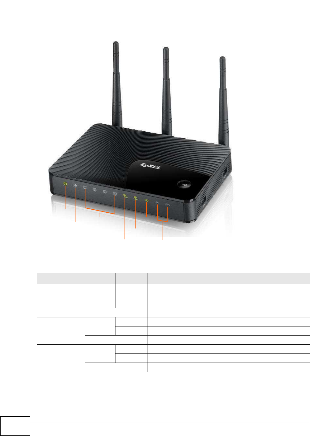
1.7 LEDs
Figure 1 Front Panel
The following table describes the LEDs.
Table 1 Front panel LEDs
LED COLOR STATUS DESCRIPTION
Power Green On The NBG5615 is receiving power and functioning properly.
Blinking The NBG5615 is in the process of starting up or default
restoring.
Off The NBG5615 is not receiving power.
WAN Green On The NBG5615’s WAN connection is ready.
Blinking The NBG5615 is sending/receiving data through the WAN.
Off The WAN connection is not ready, or has failed.
LAN 1-4 Green On The NBG5615’s LAN connection is ready.
Blinking The NBG5615 is sending/receiving data through the LAN.
Off The LAN connection is not ready, or has failed.
Pow er
LAN 1-4
WAN
2.4G WLAN USB 1/2
WPS
5G WLAN

Chapter 1 Introduction
NBG5615 User’s Guide 19
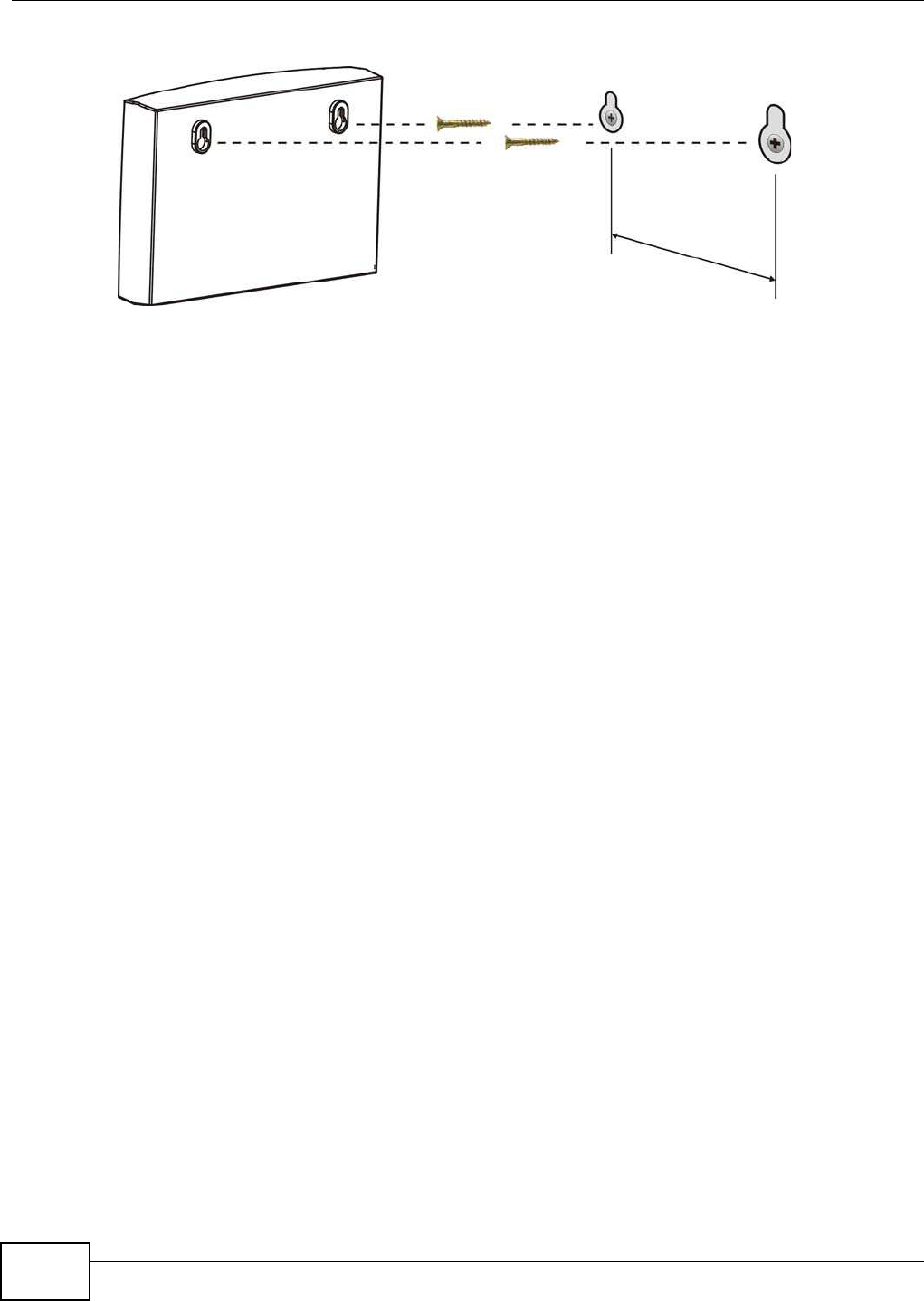
1.8 Wall Mounting
You may need screw anchors if mounting on a concrete or brick wall.
1Select a position free of obstructions on a wall strong enough to hold the weight of the device.
2Mark two holes on the wall at the appropriate distance apart for the screws.
Be careful to avoid damaging pipes or cables located inside the wall
when drilling holes for the screws.
3If using screw anchors, drill two holes for the screw anchors into the wall. Push the anchors into the
full depth of the holes, then insert the screws into the anchors. Do not insert the screws all the way
in - leave a small gap of about 0.5 cm.
If not using screw anchors, use a screwdriver to insert the screws into the wall. Do not insert the
screws all the way in - leave a gap of about 0.5 cm.
4Make sure the screws are fastened well enough to hold the weight of the NBG5615 with the
connection cables.
5Align the holes on the back of the NBG5615 with the screws on the wall. Hang the NBG5615 on the
screws.
2.4G/5G WLAN Green On The NBG5615 is ready and the 2.4GHz/5GHz wireless LAN is on,
but is not sending/receiving data through the wireless LAN.
Blinking The NBG5615 is sending/receiving data through the wireless
LAN.
Off The wireless LAN is not ready or has failed.
WPS Green On WPS is enabled.
Blinking The NBG5615 is negotiating a WPS connection with a wireless
client.
Off WPS is disabled.
USB 1/2 Green On The NBG5615 has a USB device installed.
Blinking The NBG5615 is transmitting and/or receiving data from routers
through an installed USB device.
Off There is no USB device connected to the NBG5615.
Table 1 Front panel LEDs (continued)
LED COLOR STATUS DESCRIPTION
Table 2 Wall Mounting Information
Distance between holes 13 cm
M4 Screws Two
Screw anchors (optional) Two
Chapter 1 Introduction
NBG5615 User’s Guide
20
Figure 2 Wall Mounting Example

NBG5615 User’s Guide 21
CHAPTER 2
ZyXEL NetUSB Share Center Utility
2.1 Overview
The ZyXEL NetUSB Share Center Utility allows you to work with the USB devices that are connected
directly to the NBG5615 as if they are connected directly to your computer. This allows you to easily
share USB-based devices such as printers, scanners, MP3 players, faxes, and digital cameras (to
name a few) with all the other people in your home or office as long as they are connected to the
NBG5615 and have the ZyXEL NetUSB Share Center Utility installed.
Note: Be sure to install the ZyXEL NetUSB Share Center Utility (for NetUSB functionality)
from the included disc, or download the latest version from the zyxel.com website.
2.1.1 Quick Setup
This section shows you how to get started using the ZyXEL NetUSB Share Center Utility.
1Install the ZyXEL NetUSB Share Center Utility on each computer connected to the NBG5615.
2Connect a USB device to the USB port on the NBG5615.
3Run the ZyXEL NetUSB Share Center Utility to display a list of all connected USB devices, then use
it to connect your computer to them.
2.1.2 Installing ZyXEL NetUSB Share Center Utility
Before you can access USB devices connected to the NBG5615, you must first install the ZyXEL
NetUSB Share Center Utility on any computer on your LAN to which you want to allow access to
these devices.
Note: In order to properly use the utility with your NBG5615, ensure that the NBG5615
firmware is version v1.00(AAGI.0) or higher. See Chapter 24 on page 196 for
information on updating your device’s firmware.
To install the ZyXEL NetUSB Share Center Utility:
1Insert the disc that came with your NBG5615 into your computer’s disc drive.
2Run the Setup program by double-clicking it and then follow the on-screen instructions for
installing it on your computer.
Note: The following operating systems are supported: Windows XP/Vista/7 (32 and 64-bit
versions), and Mac OS X 10.6.
Chapter 2 ZyXEL NetUSB Share Center Utility
NBG5615 User’s Guide
22
3To open the ZyXEL NetUSB Share Center Utility, double-click its system tray icon.
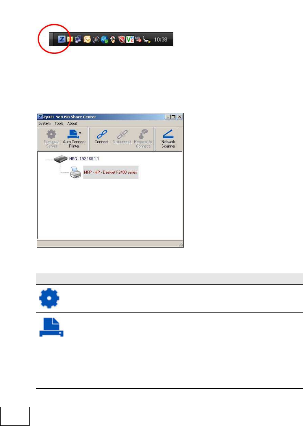
2.2 The ZyXEL NetUSB Share Center Utility
This section describes the ZyXEL NetUSB Share Center Utility main window.
Figure 3 ZyXEL NetUSB Share Center Utility Main Window
The following table describes the icons in this window.
Table 3 ZyXEL NetUSB Share Center Utility Main Window Icons
ICON DESCRIPTION
Configure Server
Click to open the NBG5615’s built-in Web Configurator, which you can use to set up the
NBG5615 (see Chapter 4 on page 39 for details).
Auto-Connect Printer
You can set the selected printer to ‘auto-connect’ after you have connected it to your
computer during inital connection. If the printer is auto-connected to your computer,
they will always be connected over the network. You do not need to configure it
manually each time.
Note: If the computer is connecting to the shared USB printer for the first time, you need
to click Connect and setup the printer before you can use the Auto-Connect
Printer function. See Chapter 9 on page 84 for more details.
Note: You first must install the appropriate drivers for the printer that you intend to use.
Chapter 2 ZyXEL NetUSB Share Center Utility
NBG5615 User’s Guide 23
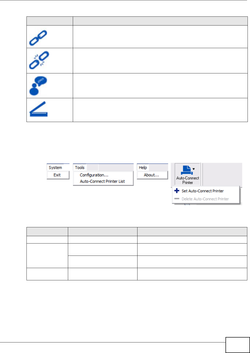
2.2.1 The Menus
This section describes the utility’s menus.
Figure 4 ZyXEL NetUSB Share Center Utility Menus
The following table describes the menus in this screen.
Connect
Select a USB device and then click this button to connect to it. Your computer can
connect to as many USB devices as are connected to the NBG5615.
Disconnect
Select a device to which your computer is connected and then click this button to
disconnect from it.
Request to Connect
Some USB devices may not allow automatic connections over the network. If so, select
the device in question and click this button to issue a request to connect to it.
Network Scanner
Click this to open the scanner options on your computer for working with a scanner
connected to the network.
Table 3 ZyXEL NetUSB Share Center Utility Main Window Icons (continued)
ICON DESCRIPTION
Table 4 ZyXEL NetUSB Share Center Utility Main Screen Menus
MENU ITEM DESCRIPTION
System Exit This closes the ZyXEL NetUSB Share Center Utility.
Tools Configuration This opens the ZyXEL NetUSB Share Center Utility
configuration window.
Auto-Connect Printer List This opens the list window that displays all of the
printing devices connected to the NBG5615.
Help About This opens the about window, which provides
information of the utility software and driver versions.
Chapter 2 ZyXEL NetUSB Share Center Utility
NBG5615 User’s Guide
24
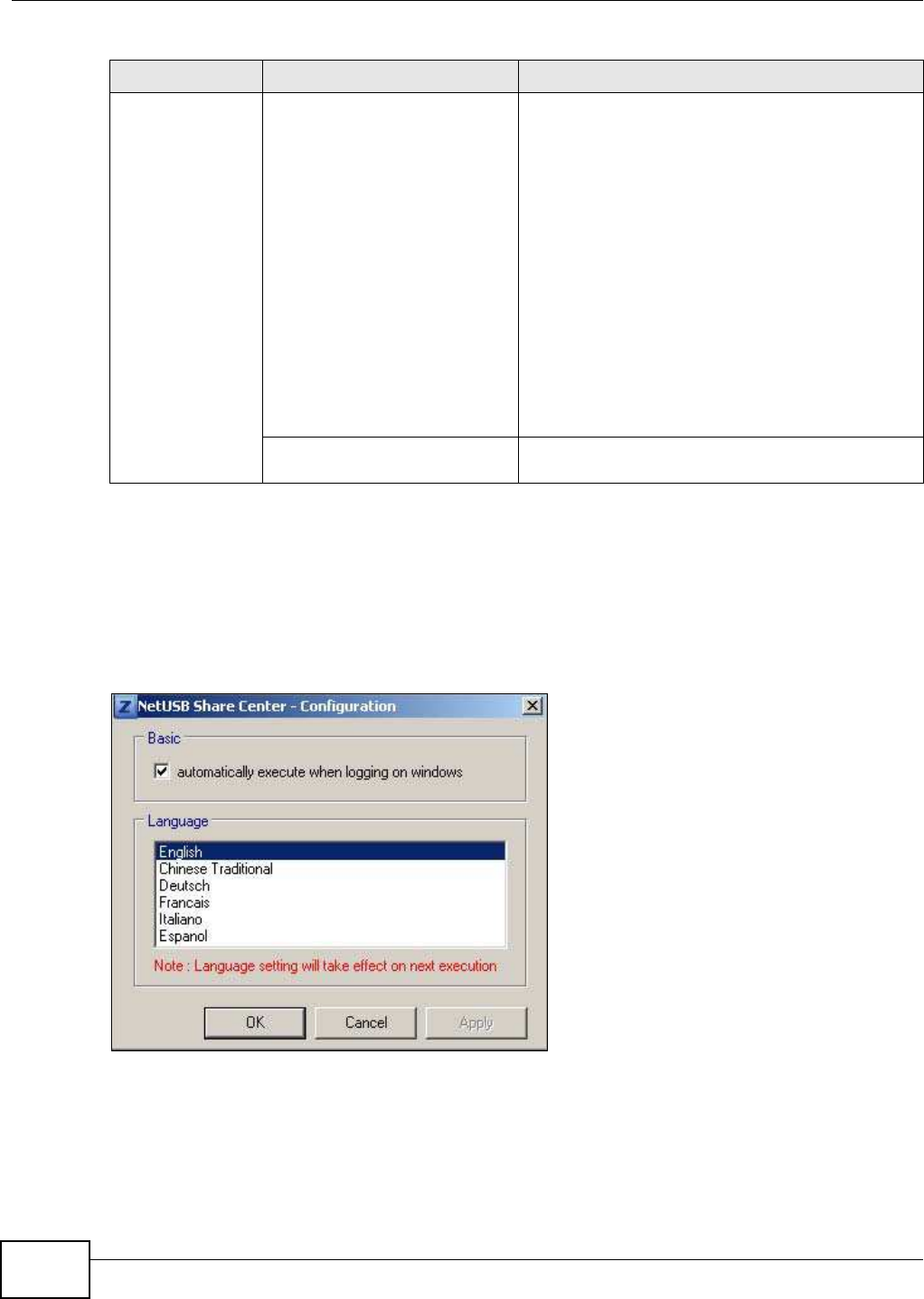
2.2.2 The ZyXEL NetUSB Share Center Configuration Window
This section describes the utility’s configuration window, which allows you to set certain options for
the utility. These options do not apply to the USB devices connected to the NBG5615.
You can open it by clicking the Tools > Configuration menu command.
Figure 5 ZyXEL NetUSB Share Center Utility Configuration Window
Auto-Connect
Printer
Set Auto-Connect Printer You can set the selected printer to ‘auto-connect’
after you have connected it to your computer during
inital connection. If the printer is auto-connected to
your computer, they will always be connected over
the network. You do not need to configure it manually
each time.
Click this to show your installed printer list and select
the one you want to set as auto-connected.
Note: If the computer is connecting to the shared USB
printer for the first time, you need to click
Connect and setup the printer before you can
use the Auto-Connect Printer function. See
Chapter 9 on page 84 for more details.
Note: You first must install the appropriate drivers for
the printer that you intend to use.
Delete Auto-Connect Printer This removes the auto-connect option from the
selected printer.
Table 4 ZyXEL NetUSB Share Center Utility Main Screen Menus (continued)
MENU ITEM DESCRIPTION
Chapter 2 ZyXEL NetUSB Share Center Utility
NBG5615 User’s Guide 25
The following table describes the labels in this window.
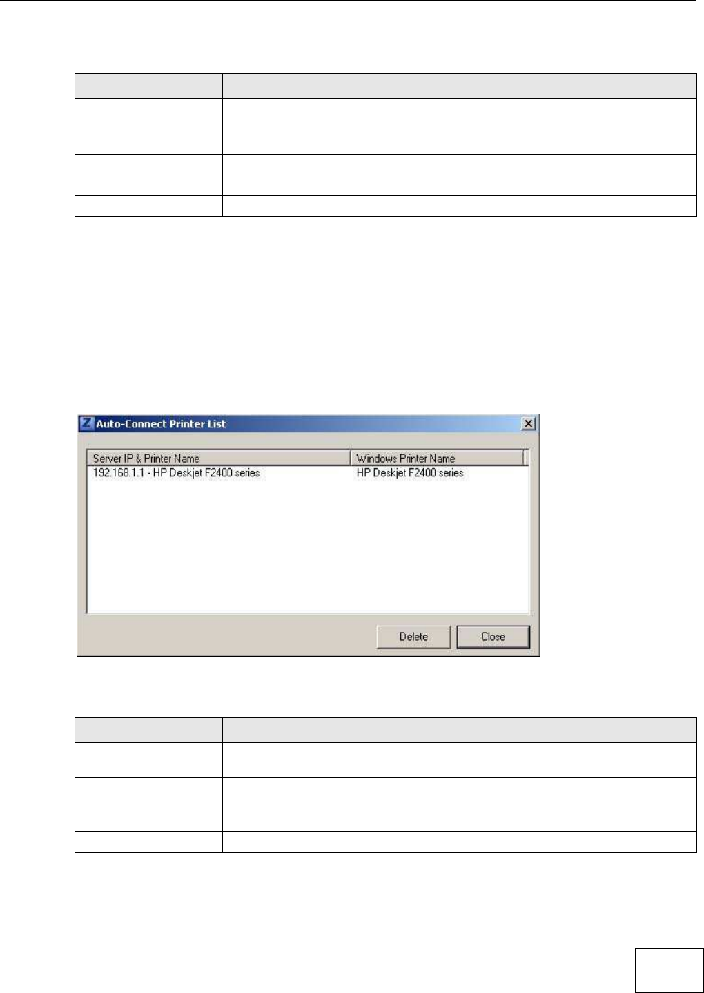
2.2.3 The Auto-Connect Printer List Window
This section describes the utility’s auto-connect printer list window. You can open it by clicking the
Tools > Auto- Connect Printer List menu command.
Note: If the computer is connecting to the shared USB printer for the first time, you need
to click Connect and setup the printer before you can use the Auto-Connect
Printer function. See Chapter 9 on page 84 for more details.
Figure 6 ZyXEL NetUSB Share Center Utility Auto-Connect Printer List Window
The following table describes the labels in this screen.
Table 5 ZyXEL NetUSB Share Center Utility Configuration Window
LABEL DESCRIPTION
Basic Select this to run the utility automatically when you log into or start up Windows.
Language Select a language for the ZyXEL NetUSB Share Center Utility. You must restart the
utility for the change to take effect.
OK Click this to save your changes and close the window.
Cancel Click this cancel to close the window without saving.
Apply Click this to save your changes without closing the window.
Table 6 ZyXEL NetUSB Share Center Utility Auto-Connect Printer List Window
LABEL DESCRIPTION
Server IP & Printer
Name
Displays a list of print server IPs and printer names connected to this NBG5615.
Windows Printer Name Displays a corresponding list of Windows printer names connected to this devices
listed in the other list.
Delete Select an printer from the list and click this to remove it.
Close Click this to close the window.
Chapter 2 ZyXEL NetUSB Share Center Utility
NBG5615 User’s Guide
26
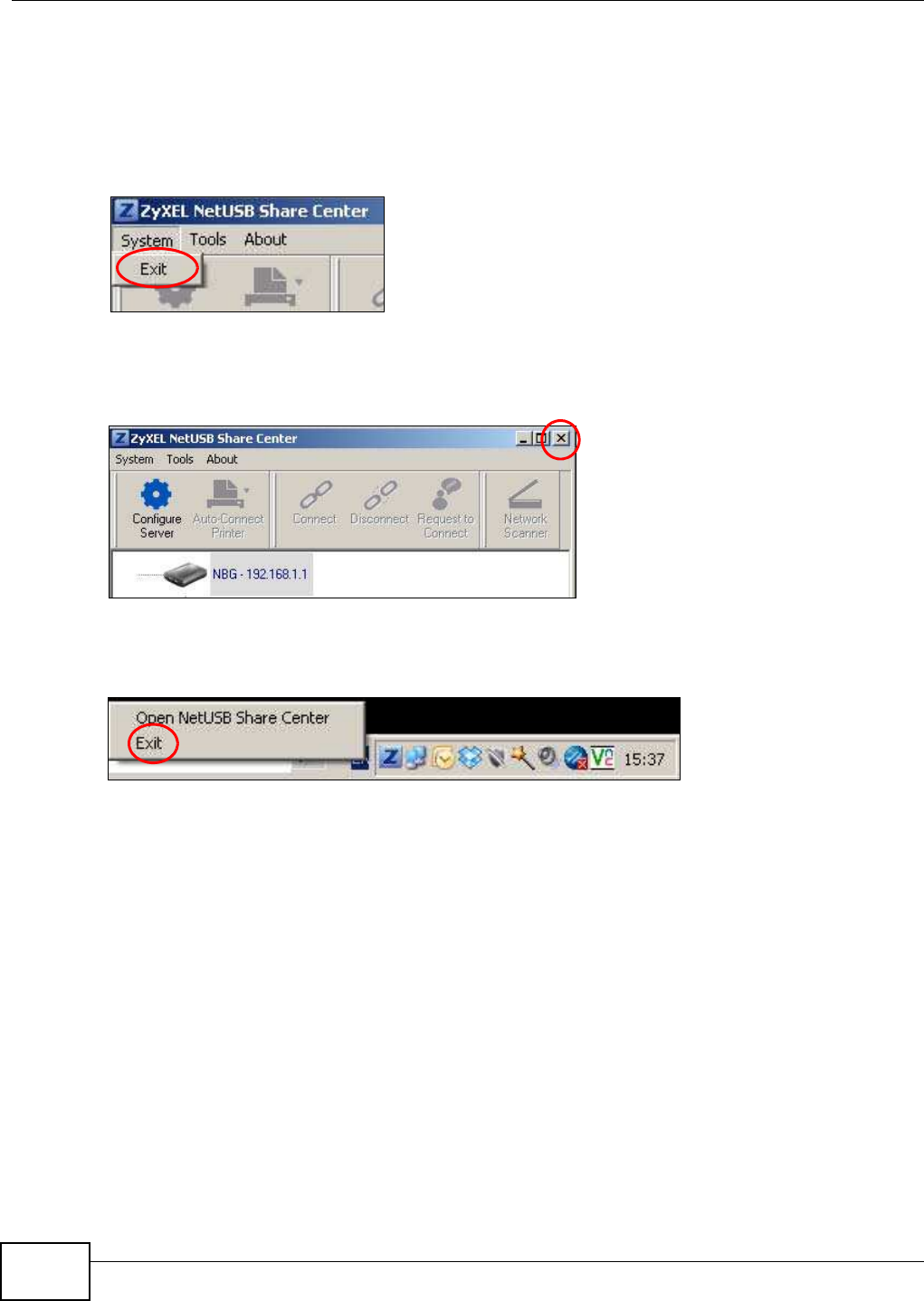
2.2.4 Exit the ZyXEL NetUSB Share Center Utility
If you want to exit the ZyXEL NetUSB Share Center Utility when your computer is not connected to
any USB device, follow the steps below:
1Click System > Exit on the Utility screen. The Utility will automatically close.
Or you can close the Utlity screen first, then exit:
1Click the X on the upper-right corner of the Utility:
2This will close the Utility screen to an icon at the system tray of your computer. Right-click on the
Utility’s icon and click Exit.
NBG5615 User’s Guide 27
CHAPTER 3
Connection Wizard
3.1 Overview
This chapter provides information on the wizard setup screens in the Web Configurator.
The Web Configurator’s wizard setup helps you configure your device to access the Internet. Refer
to your ISP for your Internet account information. Leave a field blank if you don’t have that
information.
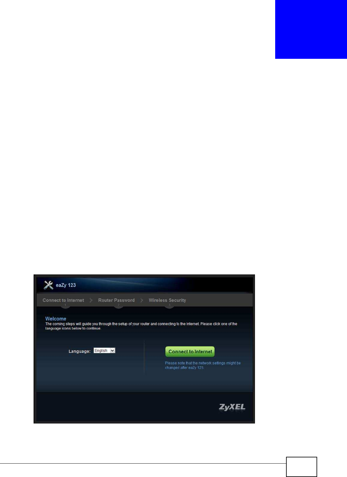
3.2 Accessing the Wizard
Launch your web browser and type "http://192.168.1.1" as the website address. Type "1234"
(default) as the password and click Login.
Note: The Wizard appears when the NBG5615 is accessed for the first time or when you
reset the NBG5615 to its default factory settings.
The Wizard screen opens. Choose your Language and click Connect to I nternet.
Figure 7 Welcome
Chapter 3 Connection Wizard
NBG5615 User’s Guide
28
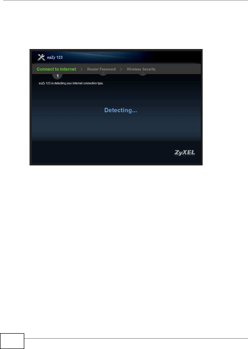
3.3 Connect to Internet
The NBG5615 offers three Internet connection types. They are I PoE, PPPoE or PPTP. The wizard
attempts to detect which WAN connection type you are using.
Figure 8 Detecting your Internet Connection Type
If the wizard does not detect a connection type, you must select one from the drop-down list box.
Check with your ISP to make sure you use the correct type.
Note: If you get an error message, check your hardware connections. Make sure your
Internet connection is up and running.
The following screen depends on your Internet connection type. Enter the details provided by your
Internet Service Provider (ISP) in the fields (if any).
Chapter 3 Connection Wizard
NBG5615 User’s Guide 29
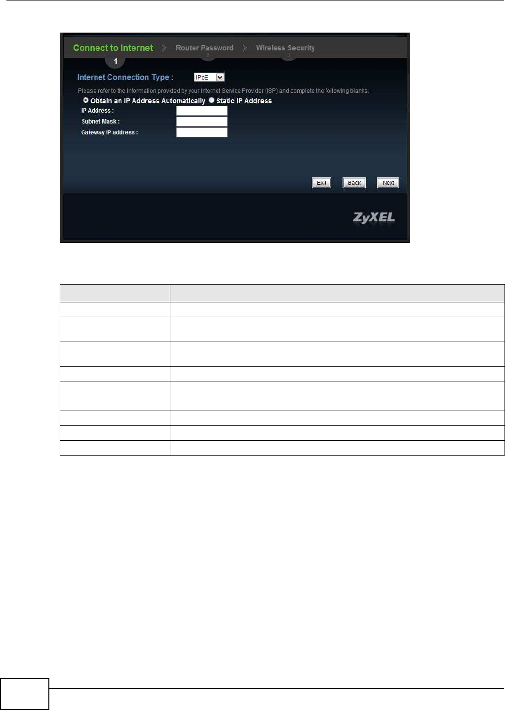
Figure 9 Internet Connection Type
Your NBG5615 detects the following Internet Connection type.
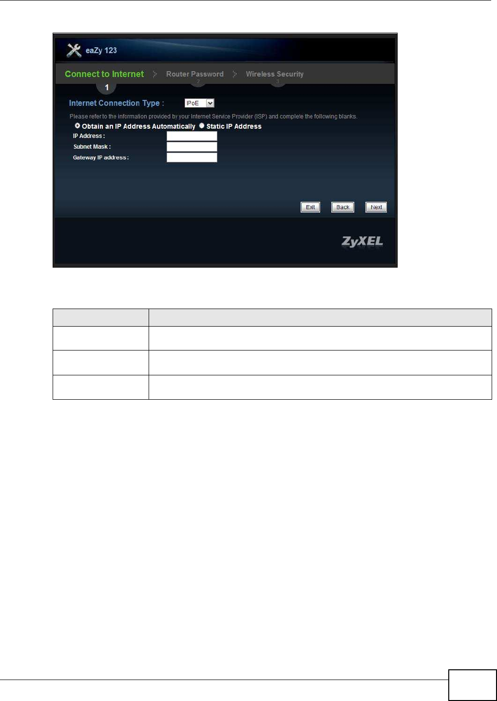
3.3.1 Connection Type: IPoE
Choose I PoE as the I nternet Connection Type when the WAN port is used as a regular Ethernet.
Click Next.
Table 7 Internet Connection Type
CONNECTION TYPE DESCRIPTION
IPoE Select the I PoE (IP over Ethernet) option when the WAN port is used as a regular
Ethernet.
PPPoE Select the PPPoE (Point-to-Point Protocol over Ethernet) option for a dial-up
connection.
PPTP Select the PPTP (Point-to-Point Tunneling Protocol) option for a dial-up connection,
and your ISP gave you an IP address and/or subnet mask.
Chapter 3 Connection Wizard
NBG5615 User’s Guide
30
Figure 10 Internet Connection Type: IPoE
The following table describes the labels in this screen.
Note: If you get an error screen after clicking Next, you might have selected the wrong
Internet Connection type. Click Back, make sure your Internet connection is
working and select the right Connection Type. Contact your ISP if you are not sure
of your Internet Connection type.
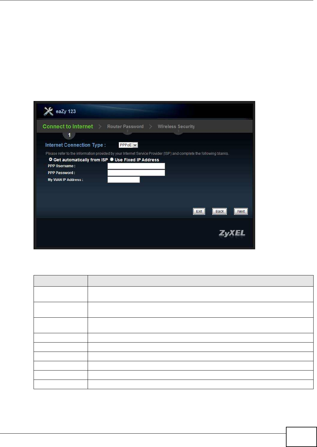
3.3.2 Connection Type: PPPoE
Point-to-Point Protocol over Ethernet (PPPoE) functions as a dial-up connection. PPPoE is an IETF
(Internet Engineering Task Force) standard specifying how a host personal computer interacts with
a broadband modem (for example DSL, cable, wireless, etc.) to achieve access to high-speed data
networks.
For the service provider, PPPoE offers an access and authentication method that works with existing
access control systems (for instance, RADIUS).
Table 8 Internet Connection Type: IPoE
LABEL DESCRIPTION
Internet Connection Type Select the I PoE option.
Obtain an IP Address
Automatically
Select this radio button if your ISP did not assign you a fixed IP address.
Static IP Address Select this radio button if your ISP assigned an IP address for your Internet
connection.
IP Address Enter the IP address provided by your ISP.
Subnet Mask Enter the IP subnet mask in this field.
Gateway IP Address Enter the gateway IP address in this field.
Exit Click this to close the wizard screen without saving.
Back Click this to return to the previous screen.
Next Click this to continue.
Chapter 3 Connection Wizard
NBG5615 User’s Guide 31
One of the benefits of PPPoE is the ability to let end users access one of multiple network services,
a function known as dynamic service selection. This enables the service provider to easily create
and offer new IP services for specific users.
Operationally, PPPoE saves significant effort for both the subscriber and the ISP/carrier, as it
requires no specific configuration of the broadband modem at the subscriber's site.
By implementing PPPoE directly on the NBG5615 (rather than individual computers), the computers
on the LAN do not need PPPoE software installed, since the NBG5615 does that part of the task.
Furthermore, with NAT, all of the LAN's computers will have Internet access.
Figure 11 Internet Connection Type: PPPoE
The following table describes the labels in this screen.
Table 9 Internet Connection Type: PPPoE
LABEL DESCRIPTION
Internet
Connection Type
Select the PPPoE option for a dial-up connection.
Get automatically
from ISP
Select this radio button if your ISP did not assign you a fixed IP address.
Use Fixed IP
Address
Select this radio button, provided by your ISP to give the NBG5615 a fixed, unique IP
address.
PPP Username Type the user name given to you by your ISP.
PPP Password Type the password associated with the user name above.
My WAN IP Address Type the name of your service provider.
Exit Click this to close the wizard screen without saving.
Back Click this to return to the previous screen.
Next Click this to continue.
Chapter 3 Connection Wizard
NBG5615 User’s Guide
32
3.3.3 Connection Type: PPTP
Point-to-Point Tunneling Protocol (PPTP) is a network protocol that enables transfers of data from a
remote client to a private server, creating a Virtual Private Network (VPN) using TCP/IP-based
networks.
PPTP supports on-demand, multi-protocol, and virtual private networking over public networks,
such as the Internet.
Refer to the appendix for more information on PPTP.
The NBG5615 supports one PPTP server connection at any given time.
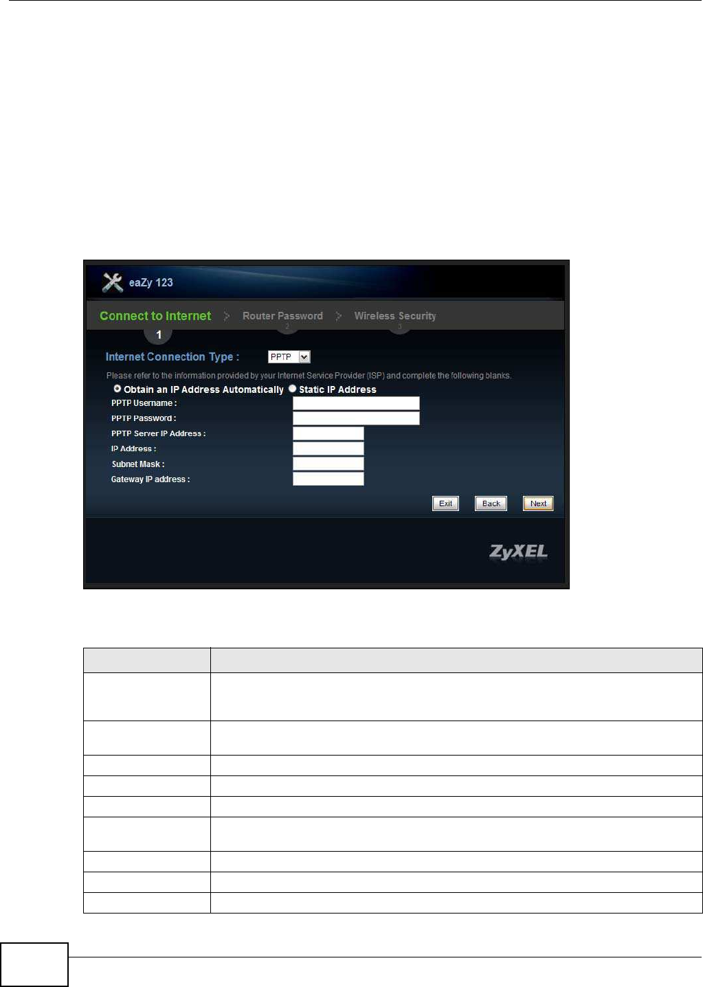
Figure 12 Internet Connection Type: PPTP
The following table describes the fields in this screen
Table 10 Internet Connection Type: PPTP
LABEL DESCRIPTION
Internet Connection
Type
Select PPTP from the drop-down list box. To configure a PPTP client, you must
configure the PPTP Usernam e and PPTP Passw ord fields for a PPP connection and
the PPTP parameters for a PPTP connection.
Obtain an IP Address
Automatically
Select this radio button if your ISP did not assign you a fixed IP address.
Static IP Address Select this radio button if your ISP assigned an IP address for your Internet connection.
PPTP Username Type the user name given to you by your ISP.
PPTP Password Type the password associated with the User Name above.
PPTP Server IP
Address
Type the server IP address of the PPTP server.
IP Address Type the (static) IP address assigned to you by your ISP.
Subnet Mask Type the subnet mask assigned to you by your ISP (if given).
Gateway IP Address Type the gateway IP address of the PPTP server.
Chapter 3 Connection Wizard
NBG5615 User’s Guide 33
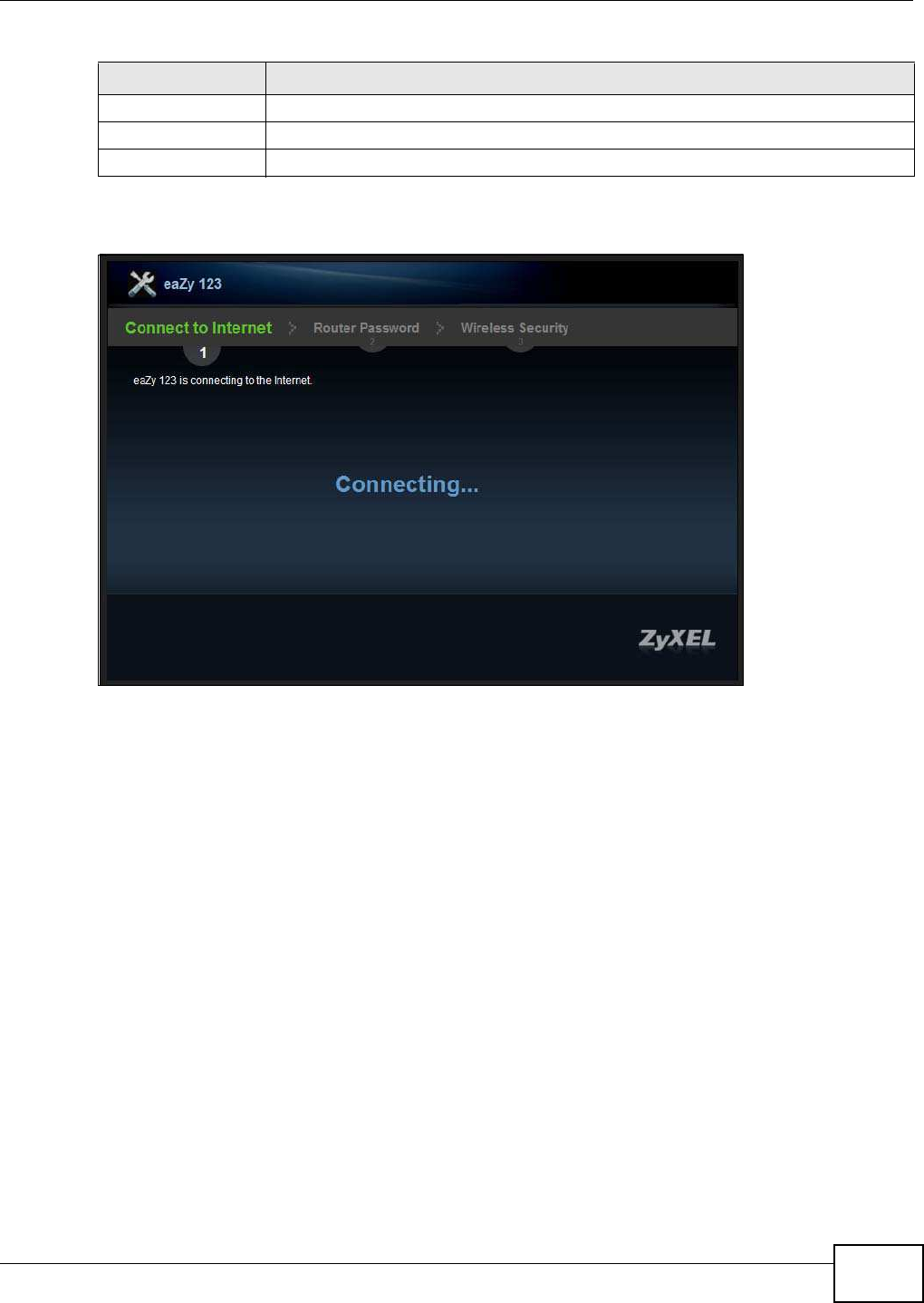
The NBG5615 connects to the Internet.
Figure 13 Connecting to the Internet
Note: If the Wizard successfully connects to the Internet, it proceeds to the next step. If
you get an error message, go back to the previous screen and make sure you have
entered the correct information provided by your ISP.
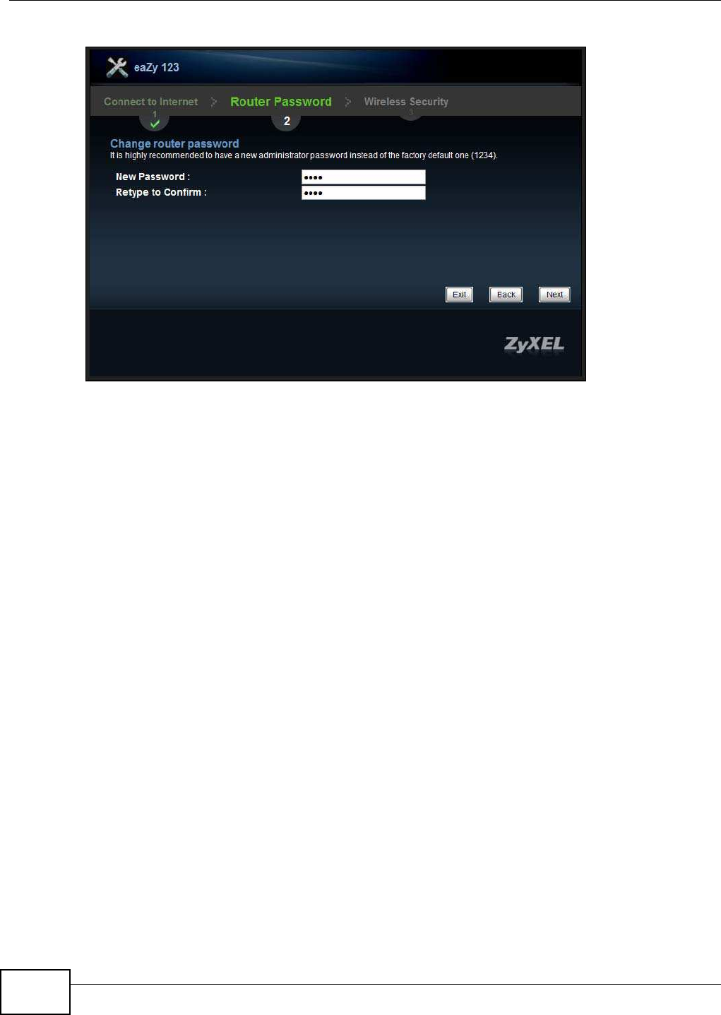
3.4 Router Password
Change the login password in the following screen. Enter the new password and retype it to
confirm. Click Next to proceed with the W ireless Security screen.
Exit Click this to close the wizard screen without saving.
Back Click this to return to the previous screen.
Next Click this to continue.
Table 10 Internet Connection Type: PPTP (continued)
LABEL DESCRIPTION
Chapter 3 Connection Wizard
NBG5615 User’s Guide
34
Figure 14 Router Password
3.5 Wireless Security
Configure Wireless Settings. Configure the wireless network settings on your NBG5615 in the
following screen. The fields that show up depend on the kind of security you select.
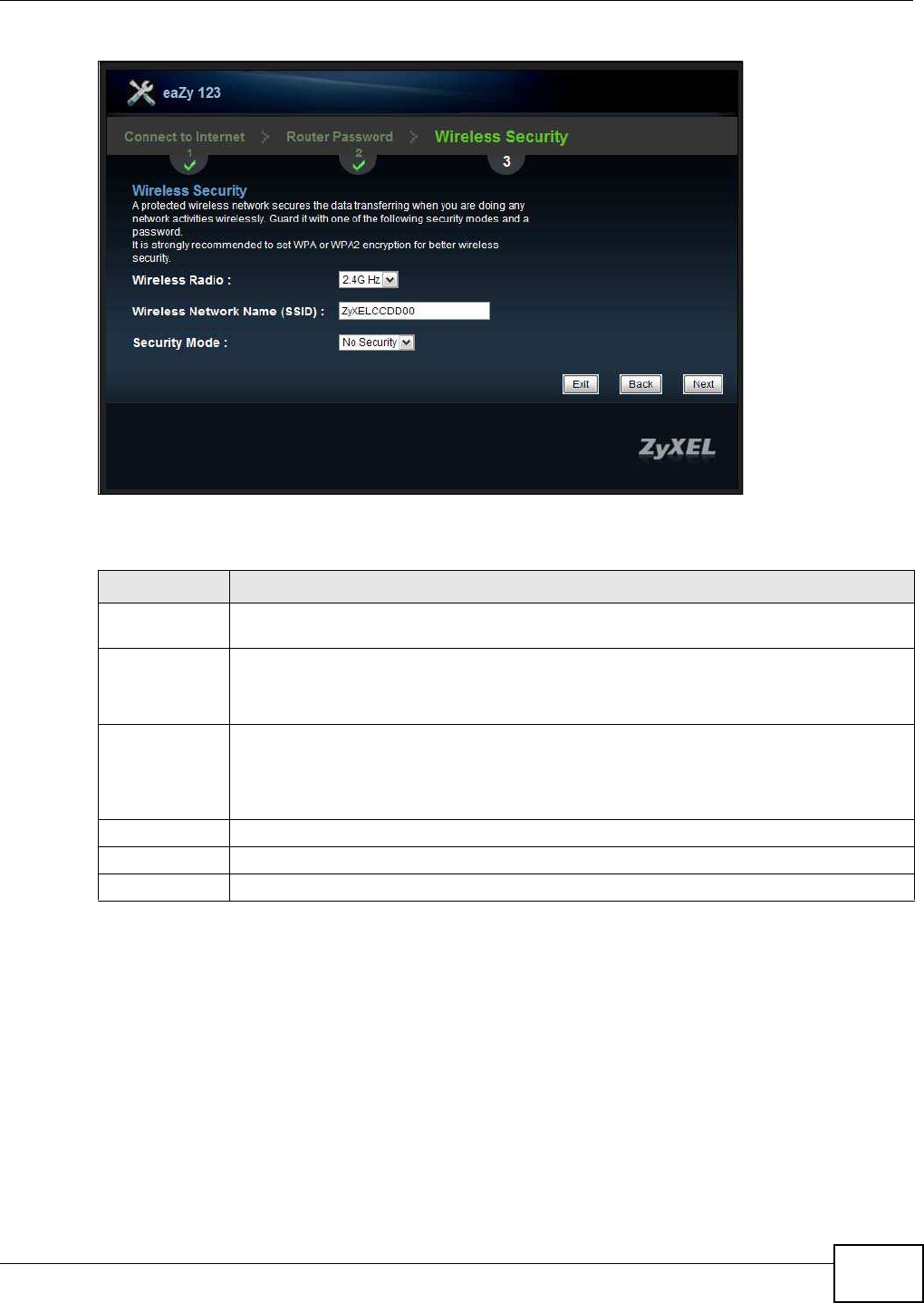
3.5.1 Wireless Security: No Security
Choose No Security in the Wireless Security screen to let wireless devices within range access
your wireless network.
Chapter 3 Connection Wizard
NBG5615 User’s Guide 35
Figure 15 Wireless Security: No Security
The following table describes the labels in this screen.
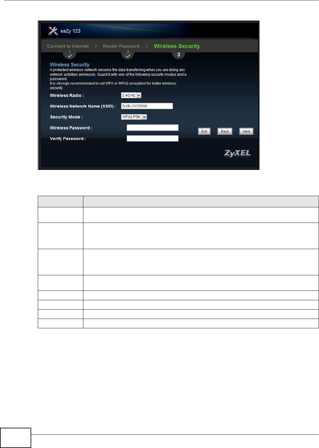
3.5.2 Wireless Security: WPA2-PSK
Choose W PA2-PSK security in the Wireless Security screen to set up a password for your wireless
network.
Table 11 Wireless Security: No Security
LABEL DESCRIPTION
Wireless Radio Choose whether you want to apply the wireless security to 2.4 G Hz or 5 G Hz wireless
radio.
Wireless
Network Name
(SSID)
Enter a descriptive name (up to 32 printable 7-bit ASCII characters) for the wireless LAN.
If you change this field on the NBG5615, make sure all wireless stations use the same SSID
in order to access the network.
Security Mode Select a security level from the drop-down list box.
Choose No Security to have no wireless LAN security configured. If you do not enable any
wireless security on your NBG5615, your network is accessible to any wireless networking
device that is within range.
Exit Click this to close the wizard screen without saving.
Back Click this to return to the previous screen.
Next Click this to continue.
Chapter 3 Connection Wizard
NBG5615 User’s Guide
36
Figure 16 Wireless Security: WPA2-PSK
The following table describes the labels in this screen.
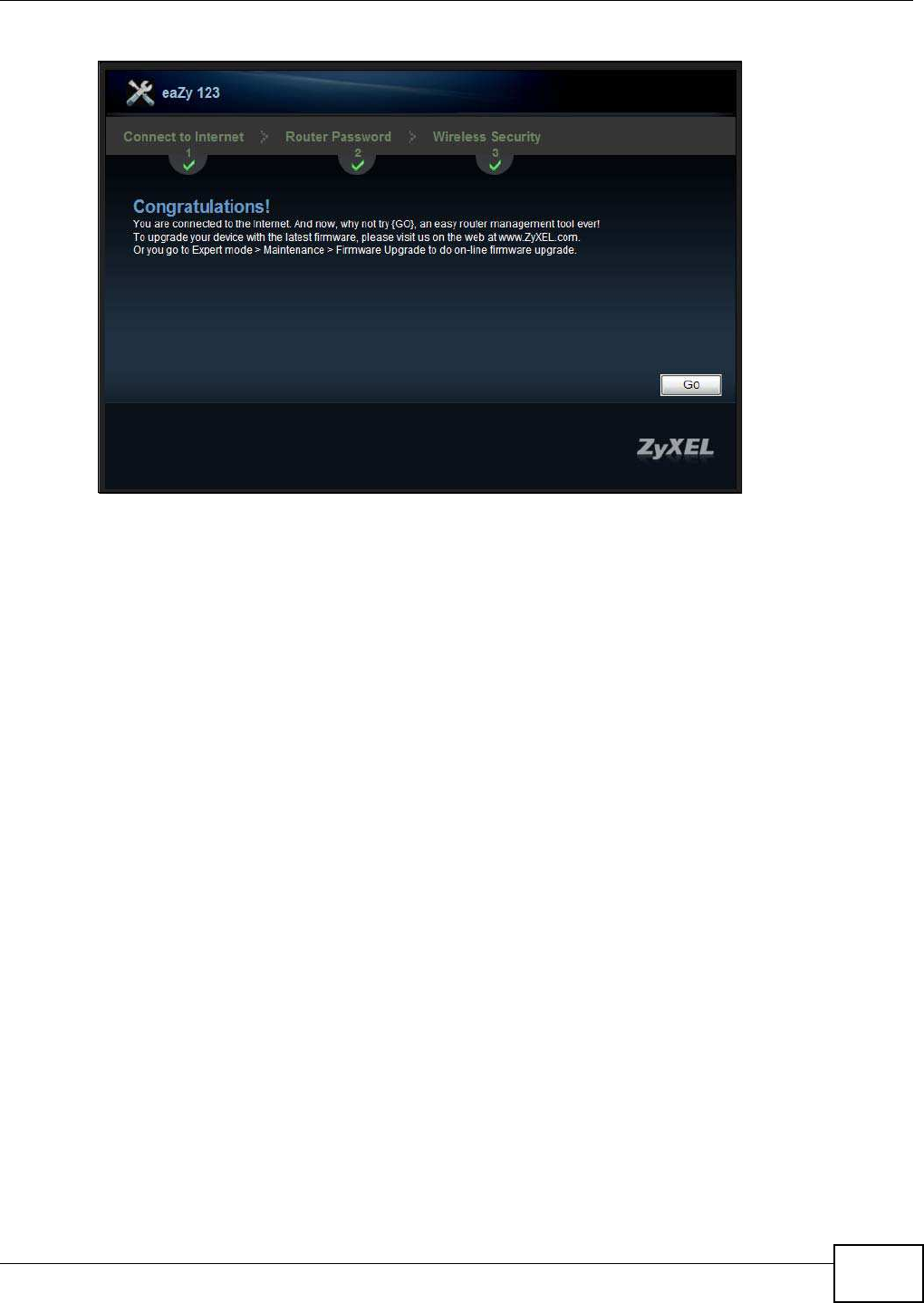
Congratulations! Open a web browser, such as Internet Explorer, to visit your favorite website.
Note: If you cannot access the Internet when your computer is connected to one of the
NBG5615’s LAN ports, check your connections. Then turn the NBG5615 off, wait for
a few seconds then turn it back on. If that does not work, log in to the web
configurator again and check you have typed all information correctly. See the
User’s Guide for more suggestions.
Table 12 Wireless Security: WPA2-PSK
LABEL DESCRIPTION
Wireless Radio Choose whether you want to apply the wireless security to 2.4G Hz or 5 G Hz wireless
radio.
Wireless
Network Name
(SSID)
Enter a descriptive name (up to 32 printable 7-bit ASCII characters) for the wireless LAN.
If you change this field on the NBG5615, make sure all wireless stations use the same SSID
in order to access the network.
Security Mode Select a security level from the drop-down list box.
Choose W PA2 -PSK security to configure a Pre-Shared Key. Choose this option only if your
wireless clients support WPA2-PSK.
Wireless
password
Type from 8 to 63 case-sensitive ASCII characters. You can set up the most secure wireless
connection by configuring WPA in the wireless LAN screens.
Verify Password Retype the password to confirm.
Exit Click this to close the wizard screen without saving.
Back Click this to return to the previous screen.
Next Click this to continue.
Chapter 3 Connection Wizard
NBG5615 User’s Guide 37
Figure 17 Congratulations
You can also click GO to open the Easy Mode Web Configurator of your NBG5615.
You have successfully set up your NBG5615 to operate on your network and access the Internet.
You are now ready to connect wirelessly to your NBG5615 and access the Internet.

Chapter 3 Connection Wizard
NBG5615 User’s Guide
38

NBG5615 User’s Guide 39
CHAPTER 4
Introducing the Web Configurator
4.1 Overview
This chapter describes how to access the NBG5615 Web Configurator and provides an overview of
its screens.
The Web Configurator is an HTML-based management interface that allows easy setup and
management of the NBG5615 via Internet browser. Use Internet Explorer 6.0 and later versions,
Mozilla Firefox 3 and later versions, or Safari 2.0 and later versions. The recommended screen
resolution is 1024 by 768 pixels.
In order to use the Web Configurator you need to allow:
• Web browser pop-up windows from your device. Web pop-up blocking is enabled by default in
Windows XP SP (Service Pack) 2.
• JavaScript (enabled by default).
• Java permissions (enabled by default).
Refer to the Troubleshooting chapter (Chapter 25 on page 203) to see how to make sure these
functions are allowed in Internet Explorer.
4.2 Accessing the Web Configurator
1Make sure your NBG5615 hardware is properly connected and prepare your computer or computer
network to connect to the NBG5615 (refer to the Quick Start Guide).
2Launch your web browser.
3The NBG5615 is in router mode by default. Type "http://192.168.1.1" as the website address.
If the NBG5615 is in access point, the IP address is 192.168.1.2. See Chapter 5 on page 43 for
more information about the modes of the NBG5615.
Your computer must be in the same subnet in order to access this website address.
4.2.1 Login Screen
Note: If this is the first time you are accessing the Web Configurator, you may be
redirected to the Wizard. Refer to Chapter 3 on page 27 for the Connection Wizard
screens.
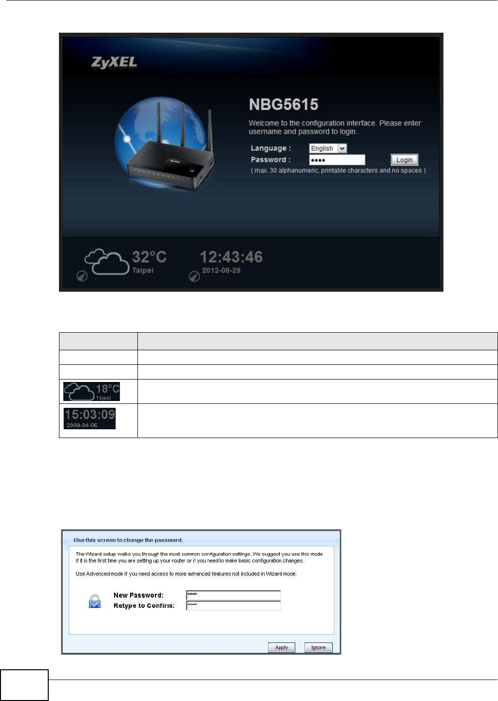
The Web Configurator initially displays the following login screen.
Chapter 4 Introducing the Web Configurator
NBG5615 User’s Guide
40
Figure 18 Login screen
The following table describes the labels in this screen.
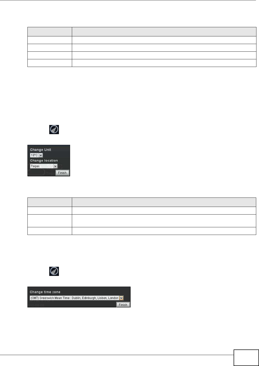
4.2.2 Password Screen
You should see a screen asking you to change your password (highly recommended) as shown
next.
Figure 19 Change Password Screen
Table 13 Login screen
LABEL DESCRIPTION
Language Select the language you want to use to configure the Web Configurator. Click Login.
Password Type "1234" (default) as the password.
This shows the current weather, either in celsius or fahrenheit, of the city you specify in
Section 4.2.2.1 on page 41.
This shows the time (hh:mm:ss) and date (yyyy:mm:dd) of the timezone you select in
Section 4.2.2.2 on page 41 or Section 24.5 on page 195. The time is in 24-hour format,
for example 15:00 is 3:00 PM.
Chapter 4 Introducing the Web Configurator
NBG5615 User’s Guide 41
The following table describes the labels in this screen.
Note: The management session automatically times out when the time period set in the
Adm inistrator I nactivity Tim er field expires (default five minutes; go to Chapter
24 on page 193 to change this). Simply log back into the NBG5615 if this happens.
4.2.2.1 Weather Edit
You can change the temperature unit and select the location for which you want to know the
weather.
Click the icon to change the Weather display.
Figure 20 Change Weather
The following table describes the labels in this screen.
4.2.2.2 Time/Date Edit
One timezone can cover more than one country. You can choose a particular country in which the
NBG5615 is located and have the NBG5615 display and use the current time and date for its logs.
Click the icon to change the time and date display.
Figure 21 Change Password Screen
Table 14 Change Password Screen
LABEL DESCRIPTION
New Password Type a new password.
Retype to Confirm Retype the password for confirmation.
Apply Click Apply to save your changes back to the NBG5615.
Ignore Click I gnore if you do not want to change the password this time.
Table 15 Change Weather
LABEL DESCRIPTION
Change Unit Choose which temperature unit you want the NBG5615 to display.
Change Location Select the location for which you want to know the weather. If the city you want is not
listed, choose one that is closest to it.
Finish Click this to apply the settings and refresh the date and time display.

Chapter 4 Introducing the Web Configurator
NBG5615 User’s Guide
42
The following table describes the labels in this screen.
Note: You can also edit the timezone in Section 24.5 on page 195.
Table 16 Change Password Screen
LABEL DESCRIPTION
Change time zone Select the specific country whose current time and date you want the NBG5615 to
display.
Finish Click this to apply the settings and refresh the weather display.

NBG5615 User’s Guide 43
CHAPTER 5
NBG5615 Modes
5.1 Overview
This chapter introduces the different modes available on your NBG5615. First, the term “mode”
refers to two things in this User’s Guide.
•W eb Configurator m ode. This refers to the Web Configurator interface you want to use for
editing NBG5615 features.
•Device m ode. This is the operating mode of your NBG5615, or simply how the NBG5615 is
being used in the network.
5.1.1 Web Configurator Modes
This refers to the configuration interface of the Web Configurator, which has two modes:
•Easy: The Web Configurator shows this mode by default. Refer to Chapter 6 on page 45 for more
information on the screens in this mode. This interface may be sufficient for users who just want
to use the device.
•Expert: Advanced users can change to this mode to customize all the functions of the NBG5615.
Click Expert Mode after logging into the Web Configurator. The User’s Guide Chapter 4 on page
39 through Chapter 24 on page 201 discusses the screens in this mode.
5.1.2 Device Modes
This refers to the operating mode of the NBG5615, which can act as a:
•Router: This is the default device mode of the NBG5615. Use this mode to connect the local
network to another network, like the Internet. Go to Section 7.2 on page 57 to view the Status
screen in this mode.
•Access Point: Use this mode if you want to extend your network by allowing network devices to
connect to the NBG5615 wirelessly. Go to Section 8.4 on page 67 to view the Status screen in
this mode.
For more information on these modes and to change the mode of your NBG5615, refer to Chapter
24 on page 201.
The menu for changing device modes is available in Expert Mode only.
Note: Choose your device mode carefully to avoid having to change it later.
When changing to another mode, the IP address of the NBG5615 changes. The running applications
and services of the network devices connected to the NBG5615 can be interrupted.

Chapter 5 NBG5615 Modes
NBG5615 User’s Guide
44
NBG5615 User’s Guide 45
CHAPTER 6
Easy Mode
6.1 Overview
The Web Configurator is set to Easy Mode by default. You can configure several key features of the
NBG5615 in this mode. This mode is useful to users who are not fully familiar with some features
that are usually intended for network administrators.
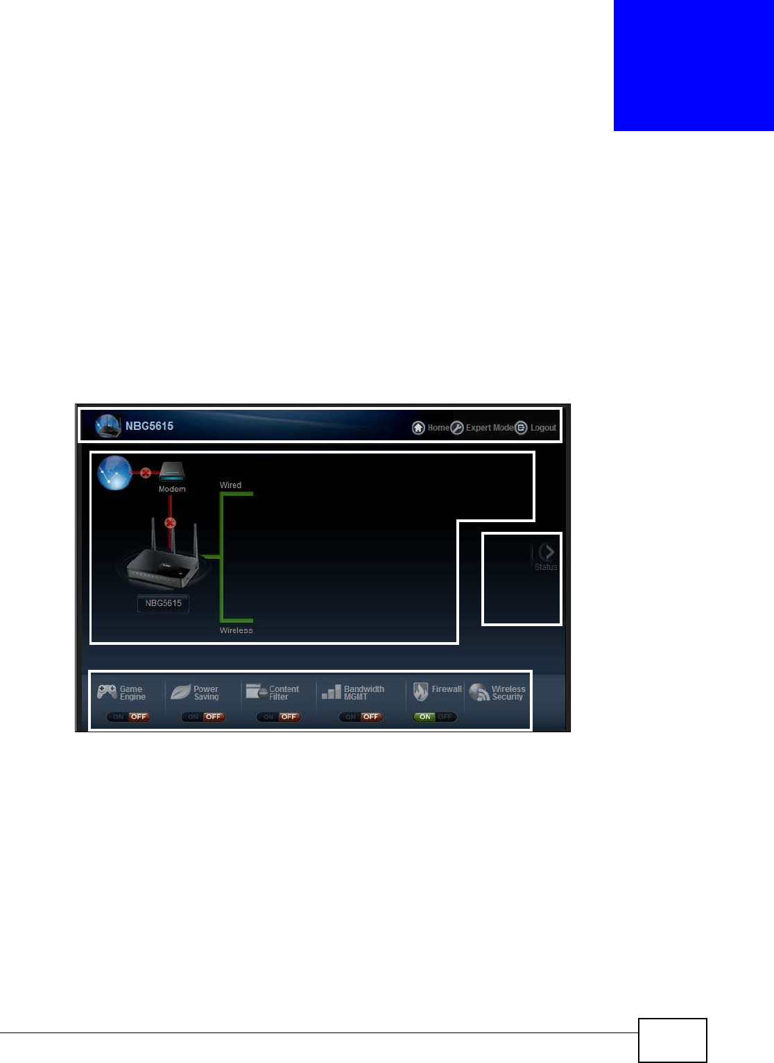
When you log in to the Web Configurator, the following screen opens.
Figure 22 Easy Mode: Network Map
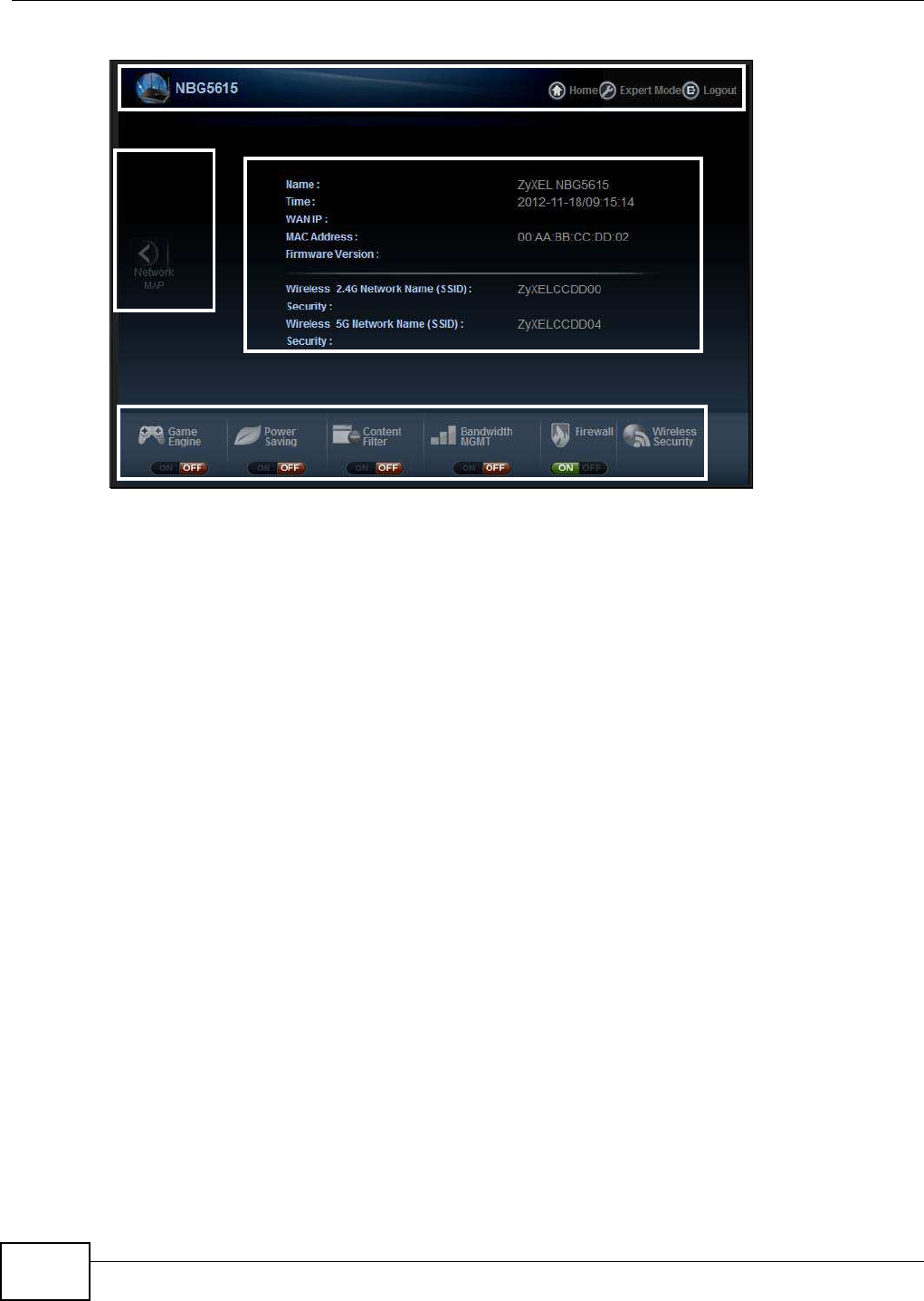
Click Status to open the following screen.
Network Map
Control Panel
Go to
Status
Screen
Navigation Panel
Chapter 6 Easy Mode
NBG5615 User’s Guide
46
Figure 23 Easy Mode: Status Screen
6.2 What You Can Do
You can do the following in this mode:
•Use this Navigation Panel to opt out of the Easy mode (Section 6.4 on page 46).
•Use the Netw ork Map screen to check if your NBG5615 can ping the gateway and whether it is
connected to the Internet (Section 6.5 on page 47).
•Use the Control Panel to configure and enable NBG5615 features, including wireless security,
wireless scheduling and bandwidth management and so on (Section 6.6 on page 48).
•Use the Status Screen to view read-only information about the NBG5615, including the WAN IP,
MAC address of the NBG5615 and the firmware version (Section 6.7 on page 54).
6.3 What You Need to Know
Between the different device modes, the Control Panel (Section 6.6 on page 48) changes
depending on which features are applicable to the mode:
•Router Mode: All Control Panel features are available.
•Access Point Mode: Only Pow er Saving and W ireless Security are available.
6.4 Navigation Panel
Use this navigation panel to opt out of the Easy mode.
Control Panel
Status Screen
Go to
Network
Map
Screen
Navigation Panel
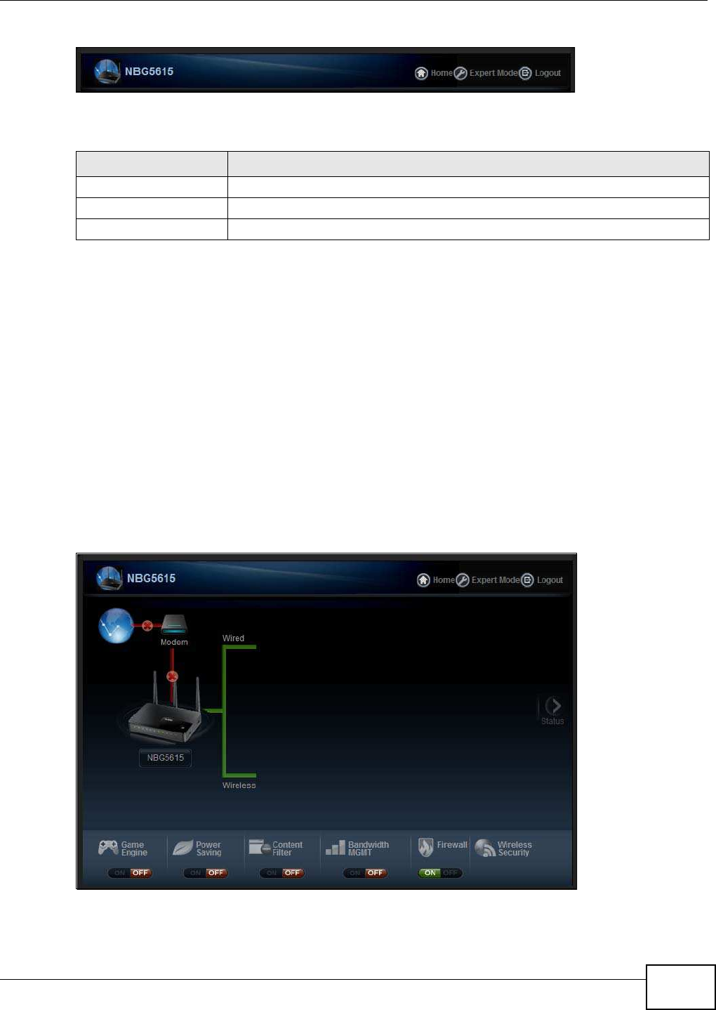
Chapter 6 Easy Mode
NBG5615 User’s Guide 47
Figure 24 Control Panel
The following table describes the labels in this screen.
6.5 Network Map
Note: The Network MAP is viewable by Windows XP (need to install patch), Windows
Vista and Windows 7 users only. For Windows XP (Service Pack 2) users, you can
see the network devices connected to the NBG5615 by downloading the LLTD (Link
Layer Topology Discovery) patch from the Microsoft Website.
Note: Don’t worry if the Network Map does not display in your web browser. This feature
may not be supported by your system. You can still configure the Control Panel
(Section 6.6 on page 48) in the Easy Mode and the NBG5615 features that you
want to use in the Expert Mode.
When you log into the Web Configurator, the Network Map is shown as follows.
Figure 25 Network Map
Table 17 Control Panel
ITEM DESCRIPTION
Home Click this to go to the Login page.
Expert Mode Click this to change to Expert Mode and customize features of the NBG5615.
Logout Click this to end the Web Configurator session.
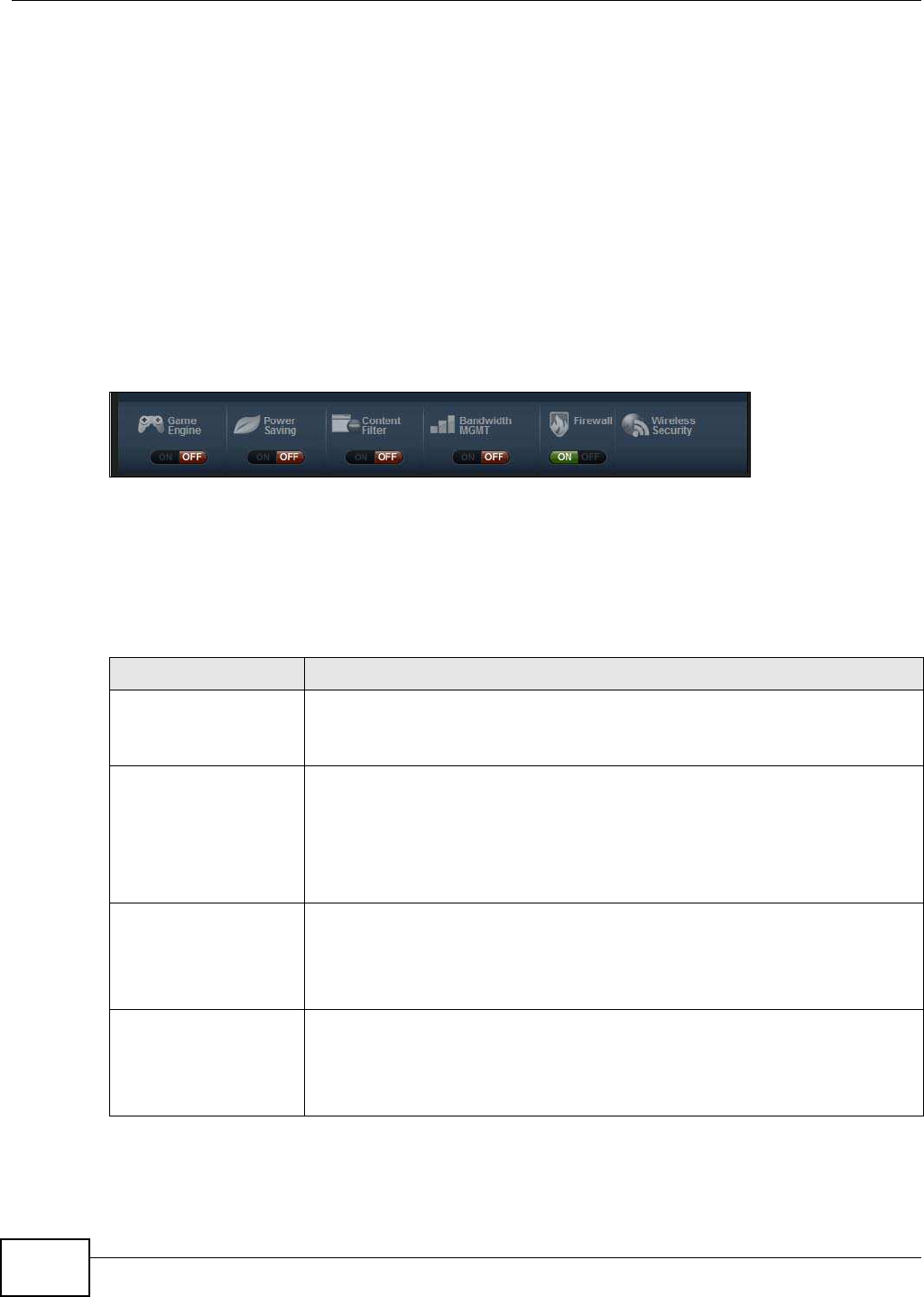
Chapter 6 Easy Mode
NBG5615 User’s Guide
48
The line connecting the NBG5615 to the gateway becomes green when the NBG5615 is able to ping
the gateway. It becomes red when the ping initiating from the NBG5615 does not get a response
from the gateway. The same rule applies to the line connecting the gateway to the Internet.
You can also view the devices (represented by icons indicating the kind of network device)
connected to the NBG5615, including those connecting wirelessly. Right-click on the NBG5615 icon
to refresh the network map and go to the Wizard. Right click on the other icons to view information
about the device.
6.6 Control Panel
The features configurable in Easy Mode are shown in the Control Panel.
Figure 26 Control Panel
Switch ON to enable the feature. Otherwise, switch OFF. If the feature is turned on, the green light
flashes. If it is turned off, the red light flashes.
Additionally, click the feature to open a screen where you can edit its settings.
The following table describes the labels in this screen.
Table 18 Control Panel
ITEM DESCRIPTION
Game Engine Switch ON to maximize bandwidth for gaming traffic in your network. Otherwise,
switch OFF.
Refer to Section 6.6.1 on page 49 to see this screen.
Power Saving Click this to schedule the wireless feature of the NBG5615.
Disabling the wireless function helps lower the energy consumption of the
NBG5615.
Switch ON to apply wireless scheduling. Otherwise, switch OFF.
Refer to Section 6.6.2 on page 49 to see this screen.
Content Filter Click this to restrict access to certain websites, based on keywords contained in
URLs, to which you do not want users in your network to open.
Switch ON to apply website filtering. Otherwise, switch OFF.
Refer to Section 6.6.3 on page 50 to see this screen.
Bandwidth MGMT Click this to edit bandwidth management for predefined applications.
Switch ON to have the NBG5615 management bandwidth for uplink and downlink
traffic according to an application or service. Otherwise, switch OFF.
Refer to Section 6.6.4 on page 51 to see this screen.
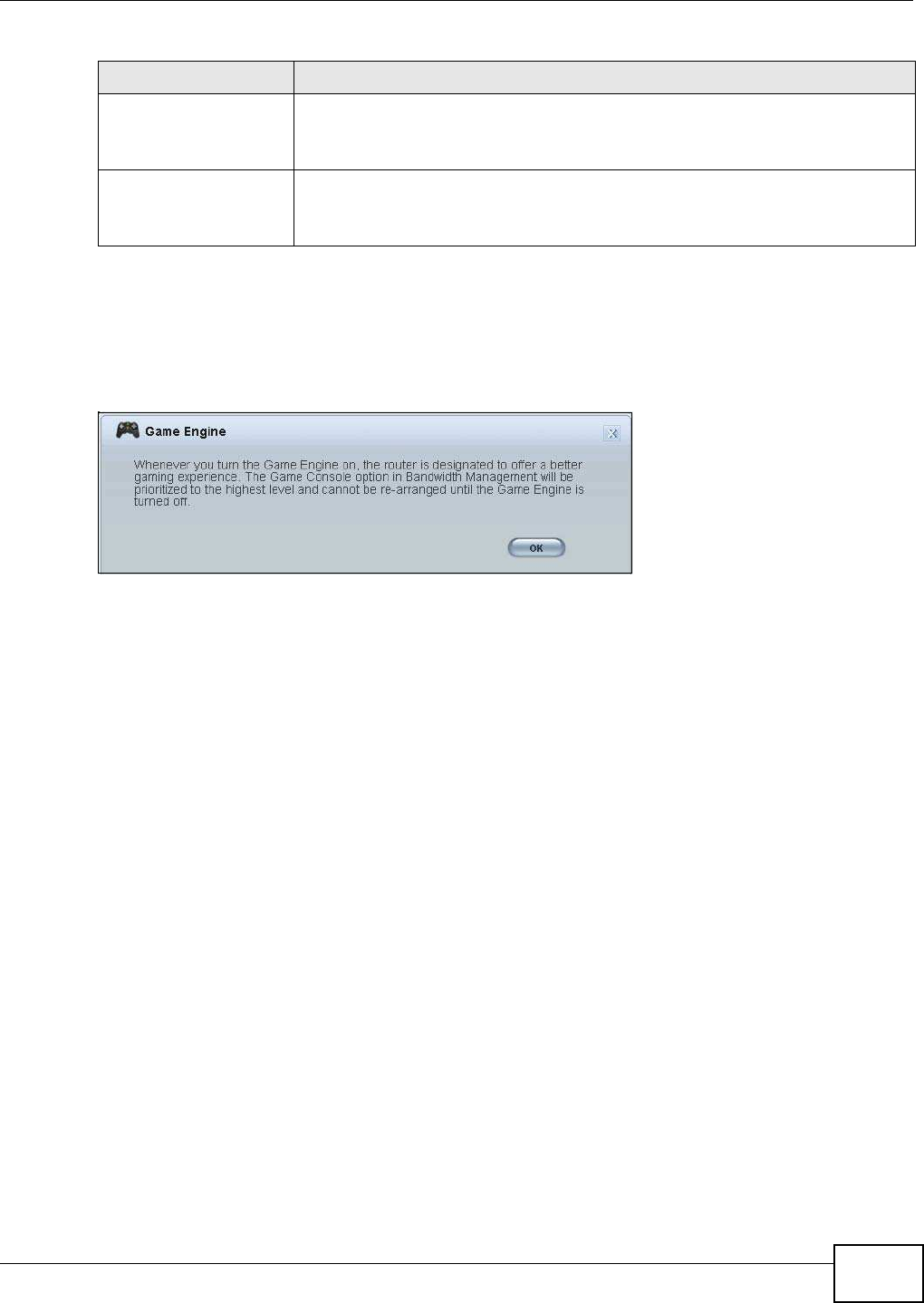
Chapter 6 Easy Mode
NBG5615 User’s Guide 49
6.6.1 Game Engine
When this feature is enabled, the NBG5615 maximizes the bandwidth for gaming traffic that
it forwards out through an interface.
Figure 27 Game Engine
Note: When this is switched on, the Gam e Console tab in the Bandw idth Mgm t screen
is automatically positioned on top.
Turn this off if your network is not using gaming.
Click OK to close this screen.
6.6.2 Power Saving
Use this screen to set the day of the week and time of the day when your wireless LAN is turned on
and off. Wireless LAN scheduling is disabled by default.
Disabling the wireless capability lowers the energy consumption of the of the NBG5615.
Firewall Switch ON to ensure that your network is protected from Denial of Service (DoS)
attacks. Otherwise, switch OFF.
Refer to Section 6.6.5 on page 52 to see this screen.
Wireless Security Click this to configure the wireless security, such as SSID, security mode and WPS
key on your NBG5615.
Refer to Section 6.6.6 on page 52 to see this screen.
Table 18 Control Panel (continued)
ITEM DESCRIPTION
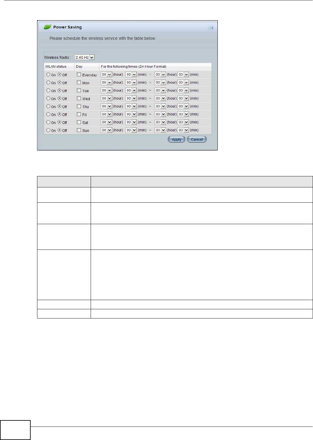
Chapter 6 Easy Mode
NBG5615 User’s Guide
50
Figure 28 Power Saving
The following table describes the labels in this screen.
6.6.3 Content Filter
Use this screen to restrict access to certain websites, based on keywords contained in URLs, to
which you do not want users in your network to open.
Table 19 Power Saving
LABEL DESCRIPTION
Wireless Radio Choose whether you want to apply the power saving schedule to 2.4G Hz or 5G Hz
wireless radio.
WLAN Status Select On or Off to specify whether the Wireless LAN is turned on or off (depending on
what you selected in the W LAN Status field). This field works in conjunction with the
Day and For the follow ing tim es fields.
Day Select Everyday or the specific days to turn the Wireless LAN on or off.
If you select Everyday you can not select any specific days. This field works in
conjunction with the For the follow ing tim es field.
For the following
times (24-Hour
Format)
Select a begin time using the first set of hour and minute (m in) drop down boxes and
select an end time using the second set of hour and minute (m in) drop down boxes. If
you have chosen On earlier for the WLAN Status the Wireless LAN will turn on between
the two times you enter in these fields. If you have chosen Off earlier for the WLAN
Status the Wireless LAN will turn off between the two times you enter in these fields.
In this time format, midnight is 00:00 and progresses up to 24:00. For example, 6:00
PM is 18:00.
Apply Click Apply to save your changes back to the NBG5615.
Cancel Click Cancel to close this screen without saving any changes.

Chapter 6 Easy Mode
NBG5615 User’s Guide 51
Figure 29 Content Filter
The following table describes the labels in this screen.
6.6.4 Bandwidth MGMT
Use this screen to set bandwidth allocation to pre-defined services and applications for bandwidth
allocation.
The NBG5615 uses bandwidth management for incoming and outgoing traffic. Rank the services
and applications by dragging them accordingly from High to Low and click Apply. Click Cancel to
close the screen.
Table 20 Content Filter
LABEL DESCRIPTION
Add Click Add after you have typed a keyword.
Repeat this procedure to add other keywords. Up to 64 keywords are allowed.
Note: The NBG5615 does not recognize wildcard characters as keywords.
When you try to access a web page containing a keyword, you will get a message telling
you that the content filter is blocking this request.
Delete Highlight a keyword in the text box and click Delete to remove it. The keyword
disappears from the text box after you click Apply.
Apply Click Apply to save your changes.
Cancel Click Cancel to close this screen without saving any changes.
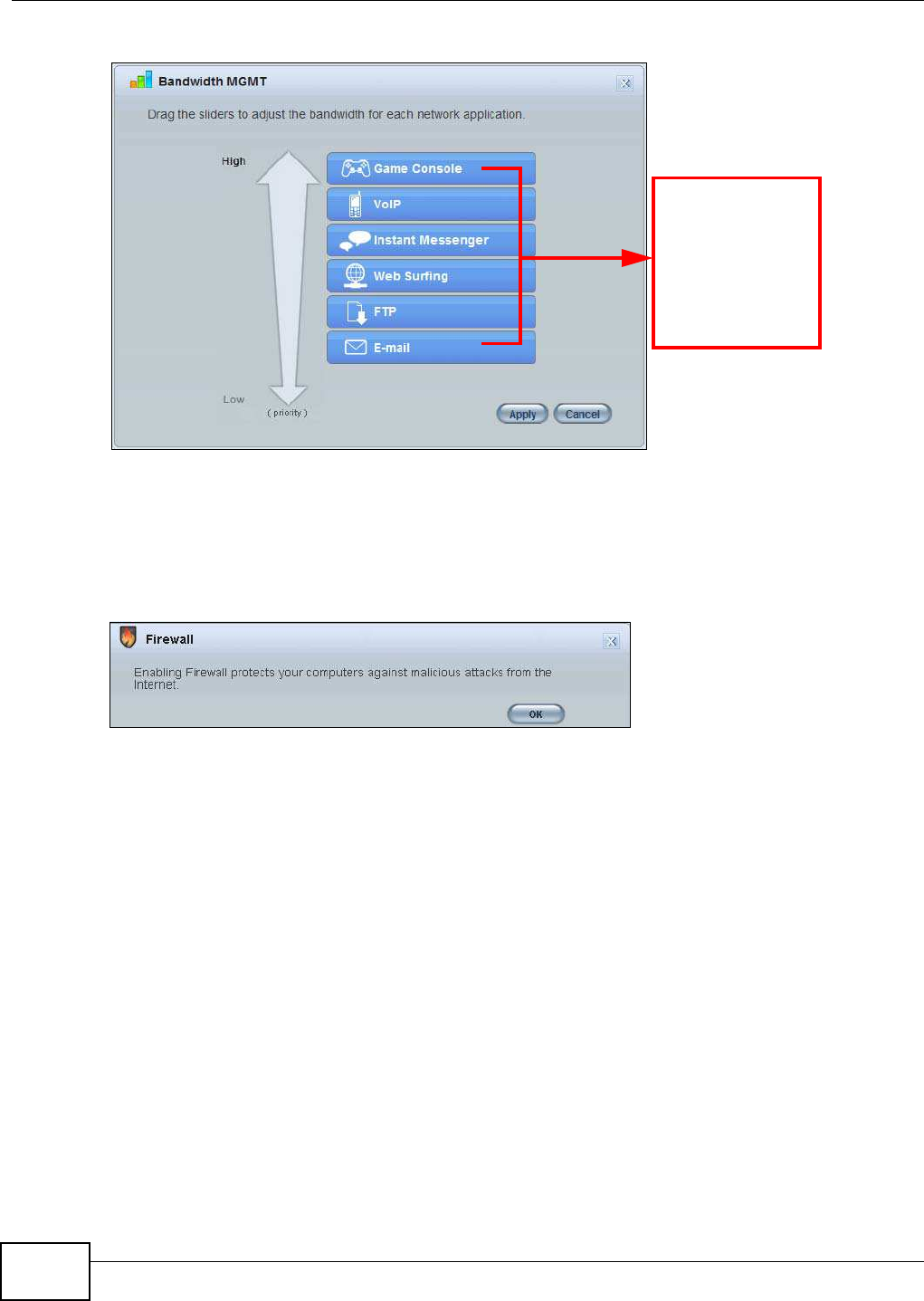
Chapter 6 Easy Mode
NBG5615 User’s Guide
52
Figure 30 Bandwidth MGNT
6.6.5 Firewall
Enable this feature to protect the network from Denial of Service (DoS) attacks. The NBG5615
blocks repetitive pings from the WAN that can otherwise cause systems to slow down or hang.
Figure 31 Firewall
Click OK to close this screen.
6.6.6 Wireless Security
Use this screen to configure security for your the wireless LAN. You can enter the SSID and select
the wireless security mode in the following screen.
Note: You can enable the wireless function of your NBG5615 by first turning on the switch
in the back panel.
Use your mouse
to drag the items
according to how
you want to
prioritize them.
Left-click and
slide up or down.
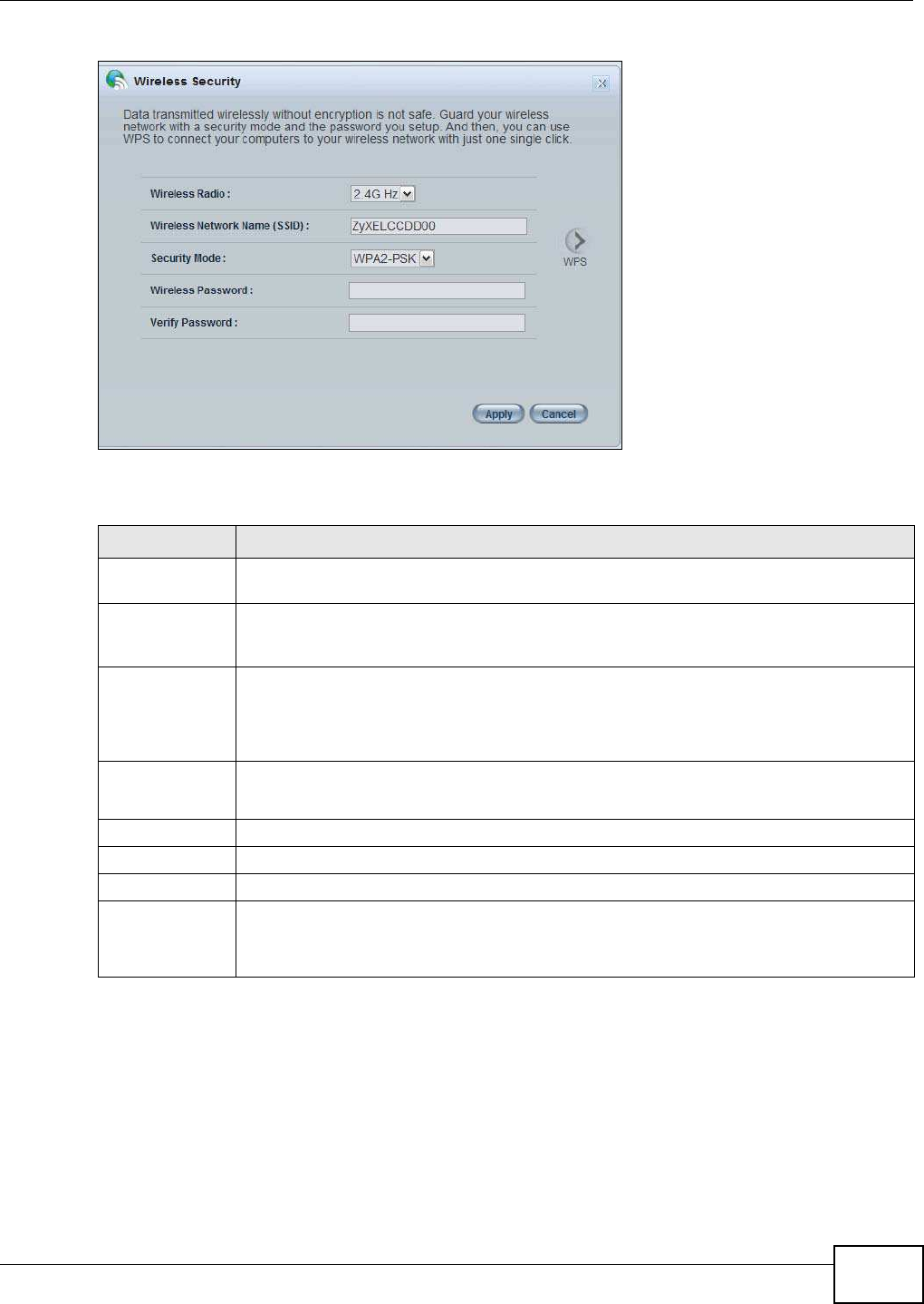
Chapter 6 Easy Mode
NBG5615 User’s Guide 53
Figure 32 Wireless Security
The following table describes the general wireless LAN labels in this screen.
6.6.7 WPS
Use this screen to add a wireless station to the network using WPS. Click W PS in the W ireless
Security to open the following screen.
Table 21 Wireless Security
LABEL DESCRIPTION
Wireless Radio Choose whether you want to apply the wireless security to 2.4 G Hz or 5 G Hz wireless
radio.
Wireless
Network Name
(SSID)
(Service Set IDentity) The SSID identifies the Service Set with which a wireless station is
associated. Wireless stations associating to the access point (AP) must have the same
SSID. Enter a descriptive name (up to 32 keyboard characters) for the wireless LAN.
Security mode Select W PA2 -PSK to add security on this wireless network. The wireless clients which
want to associate to this network must have same wireless security settings as this device.
After you select to use a security, additional options appears in this screen.
Select No Security to allow any client to connect to this network without authentication.
Wireless
password
This field appears when you choose wither W PA2 -PSK as the security mode.
Type a pre-shared key from 8 to 63 case-sensitive keyboard characters.
Verify password Type the password again to confirm.
Apply Click Apply to save your changes back to the NBG5615.
Cancel Click Cancel to close this screen.
WPS Click this to configure the WPS screen.
You can transfer the wireless settings configured here (W ireless Security screen) to
another wireless device that supports WPS.
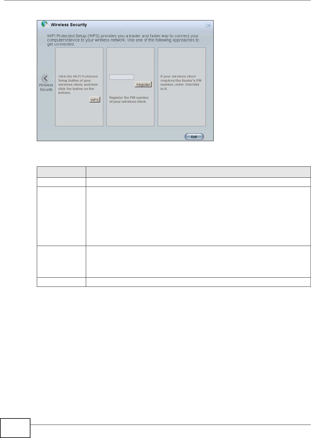
Chapter 6 Easy Mode
NBG5615 User’s Guide
54
Figure 33 Wireless Security: WPS
The following table describes the labels in this screen.
6.7 Status Screen in Easy Mode
In the Network Map screen, click Status to view read-only information about the NBG5615.
Table 22 Wireless Security: WPS
LABEL DESCRIPTION
Wireless Security Click this to go back to the W ireless Security screen.
WPS Create a secure wireless network simply by pressing a button.
The NBG5615 scans for a WPS-enabled device within the range and performs wireless
security information synchronization.
Note: After you click the WPS button on this screen, you have to press a similar button in
the wireless station utility within 2 minutes. To add the second wireless station, you
have to press these buttons on both device and the wireless station again after the
first 2 minutes.
Register Create a secure wireless network simply by entering a wireless client's PIN (Personal
Identification Number) in the NBG5615’s interface and pushing this button.
Type the same PIN number generated in the wireless station’s utility. Then click Register
to associate to each other and perform the wireless security information synchronization.
Exit Click Exit to close this screen.
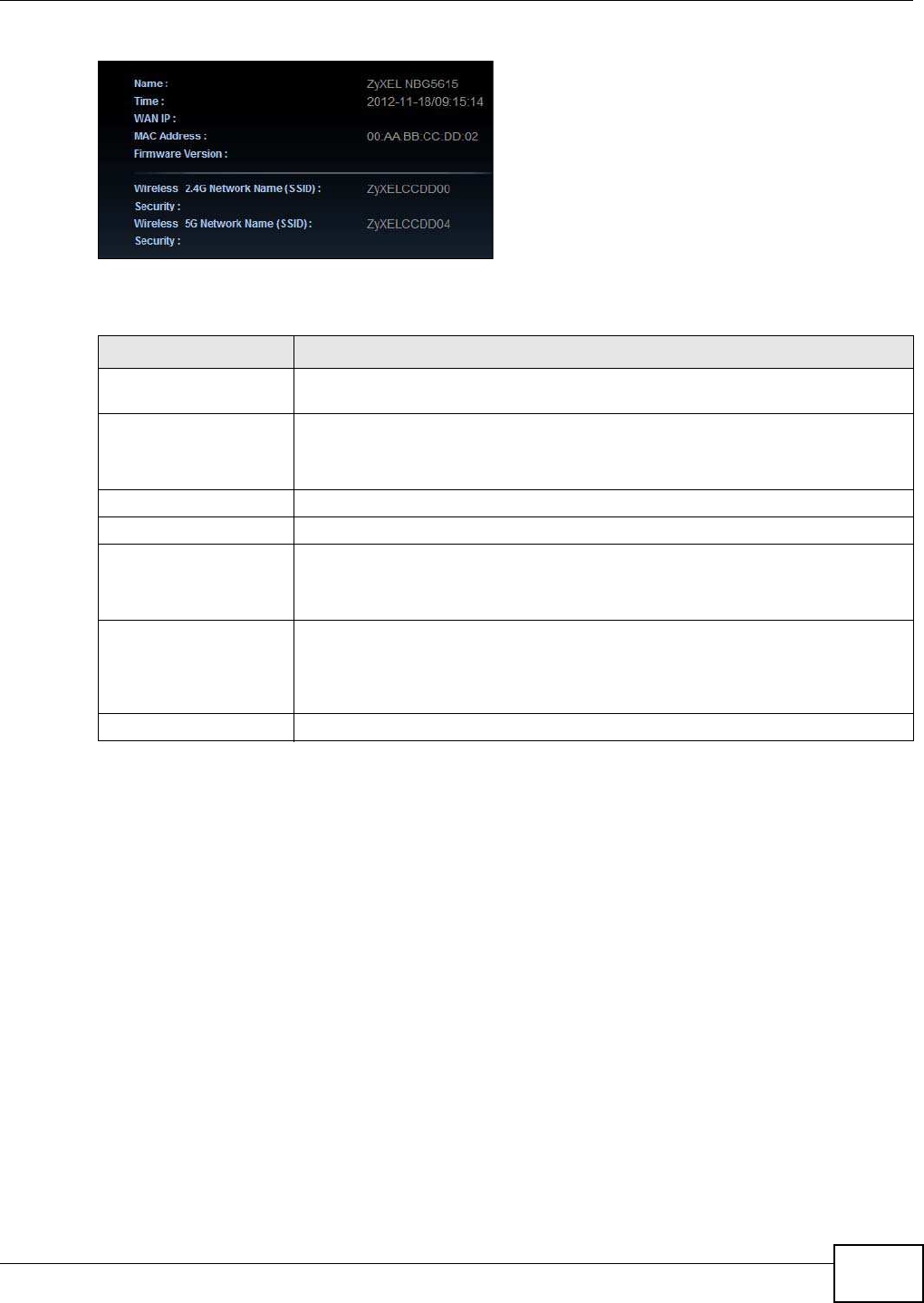
Chapter 6 Easy Mode
NBG5615 User’s Guide 55
Figure 34 Status Screen in Easy Mode
The following table describes the labels in this screen.
Table 23 Status Screen in Easy Mode
ITEM DESCRIPTION
Name This is the name of the NBG5615 in the network. You can change this in the
Maintenance > General screen in Section 24.3 on page 193.
Time This is the current system date and time.
The date is in YYYY:MM:DD (Year-Month-Day) format. The time is in HH:MM:SS
(Hour:Minutes:Seconds) format.
WAN IP This is the IP address of the WAN port.
MAC Address This is the MAC address of the NBG5615.
Firmware Version This shows the firmware version of the NBG5615.
The firmware version format shows the trunk version, model code and release
number.
Wireless 2.4G Network
Name (SSID)
Wireless 5G Network
Name (SSID)
This shows the SSID of the wireless network. You can configure this in the Wireless
Security screen (Section 6.6.6 on page 52; Section 12.2 on page 110).
Security This shows the wireless security used by the NBG5615.

Chapter 6 Easy Mode
NBG5615 User’s Guide
56
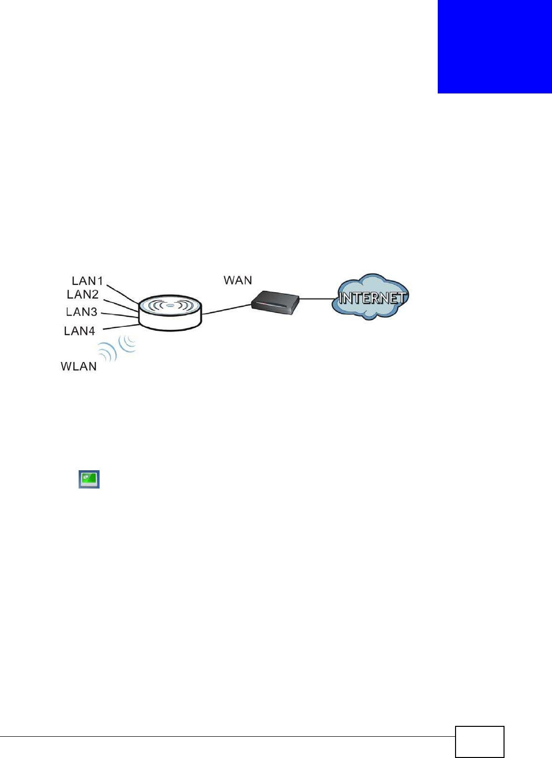
NBG5615 User’s Guide 57
CHAPTER 7
Router Mode
7.1 Overview
The NBG5615 is set to router mode by default. Routers are used to connect the local network to
another network (for example, the Internet). In the figure below, the NBG5615 connects the local
network (LAN1 ~ LAN4 ) to the Internet.
Figure 35 NBG5615 Network
Note: The Status screen is shown after changing to the Expert Mode of the Web
Configurator. It varies depending on the device mode of your NBG5615.
7.2 Router Mode Status Screen
Click to open the status screen.
Modem
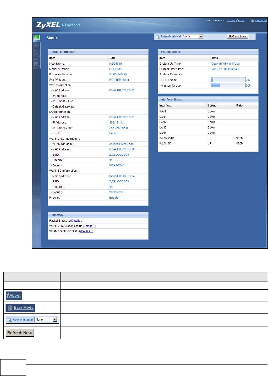
Chapter 7 Router Mode
NBG5615 User’s Guide
58
Figure 36 Status Screen: Router Mode
The following table describes the icons shown in the Status screen.
Table 24 Status Screen Icon Key
ICON DESCRIPTION
Logout Click this at any time to exit the Web Configurator.
Click this icon to view copyright and a link for related product information.
Click this icon to go to Easy Mode. See Chapter 6 on page 45.
Select a number of seconds or None from the drop-down list box to refresh all screen statistics
automatically at the end of every time interval or to not refresh the screen statistics.
Click this button to refresh the status screen statistics.
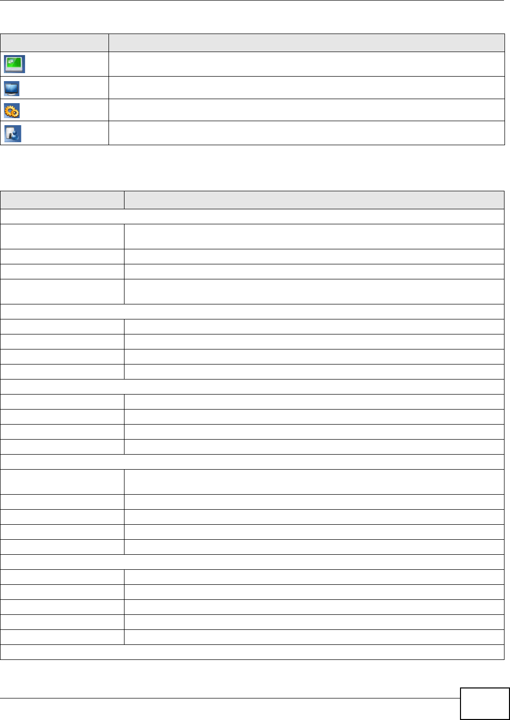
Chapter 7 Router Mode
NBG5615 User’s Guide 59
The following table describes the labels shown in the Status screen.
Click this icon to see the Status page. The information in this screen depends on the device
mode you select.
Click this icon to see the Monitor navigation menu.
Click this icon to see the Configuration navigation menu.
Click this icon to see the Maintenance navigation menu.
Table 24 Status Screen Icon Key (continued)
ICON DESCRIPTION
Table 25 Status Screen: Router Mode
LABEL DESCRIPTION
Device Information
Host Name This is the System Nam e you enter in the Maintenance > General screen. It is for
identification purposes.
Model Number This is the model name of your device.
Firmware Version This is the firmware version and the date created.
Sys OP Mode This is the device mode (Section 5.1.2 on page 43) to which the NBG5615 is set - Router
Mode.
WAN Information
MAC Address This shows the WAN Ethernet adapter MAC Address of your device.
IP Address This shows the WAN port’s IP address.
IP Subnet Mask This shows the WAN port’s subnet mask.
Default Gateway This shows the WAN port’s gateway IP address.
LAN Information
MAC Address This shows the LAN Ethernet adapter MAC Address of your device.
IP Address This shows the LAN port’s IP address.
IP Subnet Mask This shows the LAN port’s subnet mask.
DHCP This shows the LAN port’s DHCP role - Server or Disable.
WLAN 2.4G Information
WLAN OP Mode This is the device mode (Section 5.1.2 on page 43) to which the NBG5615’s wireless LAN is
set - Access Point Mode.
MAC Address This shows the 2.4GHz wireless adapter MAC Address of your device.
SSID This shows a descriptive name used to identify the NBG5615 in the 2.4GHz wireless LAN.
Channel This shows the channel number which you select manually.
Security This shows the level of wireless security the NBG5615 is using.
WLAN 5G Information
MAC Address This shows the 5GHz wireless adapter MAC Address of your device.
SSID This shows a descriptive name used to identify the NBG5615 in the 5GHz wireless LAN.
Channel This shows the channel number which you select manually.
Security This shows the level of wireless security the NBG5615 is using.
Firewall This shows whether the firewall is enabled or not.
Summary

Chapter 7 Router Mode
NBG5615 User’s Guide
60
7.2.1 Navigation Panel
Use the sub-menus on the navigation panel to configure NBG5615 features.
Packet Statistics Click Details... to go to the Monitor > Packet Statistics screen (Section 10.5 on page
91). Use this screen to view port status and packet specific statistics.
WLAN 2.4G Station
Status Click Details... to go to the Monitor > W LAN 2 .4 G Station Status screen (Section 10.6
on page 92). Use this screen to view the wireless stations that are currently associated to
the NBG5615’s 2.4GHz wireless LAN.
WLAN 5G Station Status Click Details... to go to the Monitor > W LAN 5 G Station Status screen (Section 10.6 on
page 92). Use this screen to view the wireless stations that are currently associated to the
NBG5615’s 5GHz wireless LAN.
System Status
Item This column shows the type of data the NBG5615 is recording.
Data This column shows the actual data recorded by the NBG5615.
System Up Time This is the total time the NBG5615 has been on.
Current Date/Time This field displays your NBG5615’s present date and time.
System Resource
- CPU Usage This displays what percentage of the NBG5615’s processing ability is currently used. When
this percentage is close to 100%, the NBG5615 is running at full load, and the throughput is
not going to improve anymore. If you want some applications to have more throughput, you
should turn off other applications (for example, using bandwidth management.)
- Memory Usage This shows what percentage of the heap memory the NBG5615 is using.
Interface Status
Interface This displays the NBG5615 port types. The port types are: W AN, LAN and W LAN.
Status For the LAN and WAN ports, this field displays Dow n (line is down) or Up (line is up or
connected).
For the 2.4GHz/5GHz WLAN, it displays Up when the 2.4GHz/5GHz WLAN is enabled or
Dow n when the 2.4G/5G WLAN is disabled.
Rate For the LAN ports, this displays the port speed and duplex setting or N/ A when the line is
disconnected.
For the WAN port, it displays the port speed and duplex setting if you’re using Ethernet
encapsulation. This field displays N/ A when the line is disconnected.
For the 2.4GHz/5GHz WLAN, it displays the maximum transmission rate when the 2.4GHz/
5GHz WLAN is enabled and N/ A when the WLAN is disabled.
Table 25 Status Screen: Router Mode (continued)
LABEL DESCRIPTION
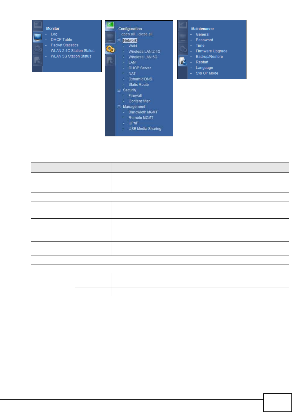
Chapter 7 Router Mode
NBG5615 User’s Guide 61
Figure 37 Navigation Panel: Router Mode
The following table describes the sub-menus.
Table 26 Navigation Panel: Router Mode
LINK TAB FUNCTION
Status This screen shows the NBG5615’s general device, system and interface
status information. Use this screen to access the wizard, and summary
statistics tables.
MONI TOR
Log Use this screen to view the list of activities recorded by your NBG5615.
DHCP Table Use this screen to view current DHCP client information.
Packet Statistics Use this screen to view port status and packet specific statistics.
WLAN 2.4G
Station Status
Use this screen to view the wireless stations that are currently associated
to the NBG5615’s 2.4GHz wireless LAN.
WLAN 5G
Station Status
Use this screen to view the wireless stations that are currently associated
to the NBG5615’s 5GHz wireless LAN.
CONFI GURATI ON
Network
WAN Internet
Connection
This screen allows you to configure ISP parameters, WAN IP address
assignment, DNS servers and the WAN MAC address.
Advanced Use this screen to configure other advanced properties.

Chapter 7 Router Mode
NBG5615 User’s Guide
62
Wireless LAN
2.4G/5G General Use this screen to enable the wireless LAN and configure wireless LAN and
wireless security settings.
More AP Use this screen to configure multiple BSSs on the NBG5615.
MAC Filter Use the MAC filter screen to configure the NBG5615 to block access to
devices or block the devices from accessing the NBG5615.
Advanced This screen allows you to configure advanced wireless settings.
QoS Use this screen to configure Wi-Fi Multimedia Quality of Service (WMM
QoS). WMM QoS allows you to prioritize wireless traffic according to the
delivery requirements of individual services.
WPS Use this screen to configure WPS.
WPS Station Use this screen to add a wireless station using WPS.
Scheduling Use this screen to schedule the times the Wireless LAN is enabled.
LAN IP Use this screen to configure LAN IP address and subnet mask.
IP Alias Use this screen to have the NBG5615 apply IP alias to create LAN subnets.
DHCP Server General Use this screen to enable the NBG5615’s DHCP server.
Advanced Use this screen to assign IP addresses to specific individual computers
based on their MAC addresses and to have DNS servers assigned by the
DHCP server.
Client List Use this screen to view information related to your DHCP status.
NAT General Use this screen to enable NAT.
Port
Forwarding
Use this screen to configure servers behind the NBG5615 and forward
incoming service requests to the server(s) on your local network.
Port Trigger Use this screen to change your NBG5615’s port triggering settings.
Dynamic
DNS Dynamic DNS Use this screen to set up dynamic DNS.
Static Route Static Route Use this screen to configure IP static routes.
Security
Firewall General Use this screen to activate/deactivate the firewall.
Services This screen shows a summary of the firewall rules, and allows you to edit/
add a firewall rule.
Content
Filter Content Filter Use this screen to block certain web features and sites containing certain
keywords in the URL.
Management
Bandwidth
Management General Use this screen to enable bandwidth management.
Advanced Use this screen to set the upstream bandwidth and edit a bandwidth
management rule.
Remote
Management WWW Use this screen to configure through which interface(s) and from which IP
address(es) users can use HTTP to manage the NBG5615.
Telnet Use this screen to configure through which interface(s) and from which IP
address(es) users can use Telnet to manage the NBG5615.
Wake On LAN Use this screen to enable Wake on LAN to remotely turn on a device on the
local network.
UPnP General Use this screen to enable UPnP on the NBG5615.
Table 26 Navigation Panel: Router Mode (continued)
LINK TAB FUNCTION

Chapter 7 Router Mode
NBG5615 User’s Guide 63
USB Media
Sharing DLNA Use this screen to have the NBG5615 function as a DLNA-compliant media
server, that lets DLNA-compliant media clients play video, audio, and photo
content files stored on the connected USB storage device.
SAMBA Use this screen to enable file sharing through the NBG5615.
FTP Use this screen to have the NBG5615 act as a FTP server.
MAI NTENANCE
General General Use this screen to view and change administrative settings such as system
and domain names.
Password Password
Setup
Use this screen to change the password of your NBG5615.
Time Time Setting Use this screen to change your NBG5615’s time and date.
Firmware
Upgrade Firmware
Upgrade
Use this screen to upload firmware to your NBG5615.
Backup/
Restore Backup/
Restore
Use this screen to backup and restore the configuration or reset the factory
defaults to your NBG5615.
Restart System
Restart
This screen allows you to reboot the NBG5615 without turning the power
off.
Language Language This screen allows you to select the language you prefer.
Sys OP Mode Sys OP Mode This screen allows you to select whether your device acts as a router, or an
access point.
Table 26 Navigation Panel: Router Mode (continued)
LINK TAB FUNCTION

Chapter 7 Router Mode
NBG5615 User’s Guide
64
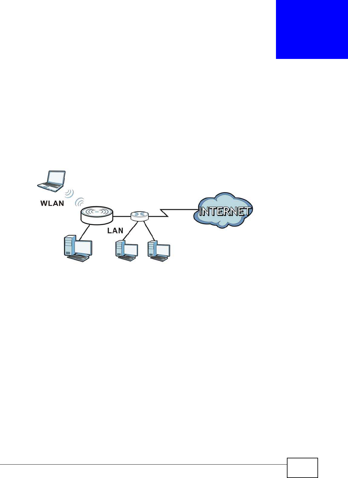
NBG5615 User’s Guide 65
CHAPTER 8
Access Point Mode
8.1 Overview
Use your NBG5615 as an access point (AP) if you already have a router or gateway on your
network. In this mode your NBG5615 bridges a wired network (LAN) and wireless LAN (WLAN) in
the same subnet. See the figure below for an example.
Figure 38 Wireless Internet Access in Access Point Mode
Many screens that are available in Router Mode are not available in Access Point Mode, such as
bandwidth management and firewall.
Note: See Chapter 9 on page 73 for an example of setting up a wireless network in
Access Point mode.
8.2 What You Can Do
•Use the Status screen to view read-only information about your NBG5615 (Section 8.4 on page
67).
•Use the LAN screen to set the IP address for your NBG5615 acting as an access point (Section
8.5 on page 69).
8.3 What You Need to Know
See Chapter 9 on page 73 for a tutorial on setting up a network with the NBG5615 as an access
point.
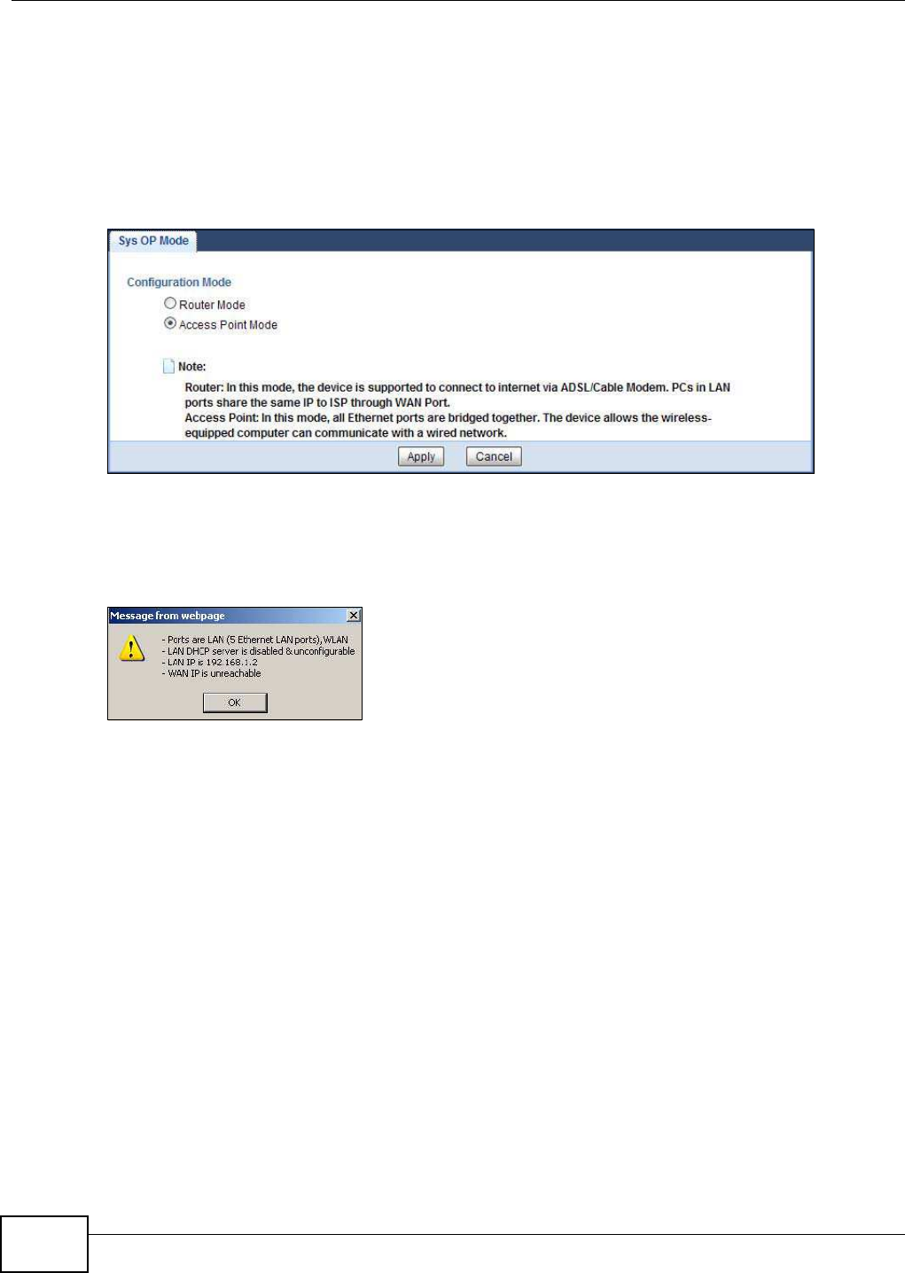
Chapter 8 Access Point Mode
NBG5615 User’s Guide
66
8.3.1 Setting your NBG5615 to AP Mode
1Log into the Web Configurator if you haven’t already. See the Quick start Guide for instructions on
how to do this.
2To use your NBG5615 as an access point, go to Maintenance > Sys OP Mode and select Access
Point Mode.
Figure 39 Changing to Access Point mode
Note: You have to log in to the Web Configurator again when you change modes. As soon
as you do, your NBG5615 is already in Access Point mode.
3When you select Access Point Mode, the following pop-up message window appears.
Figure 40 Pop up for Access Point mode
Click OK. Then click Apply. The Web Configurator refreshes once the change to Access Point mode
is successful.
8.3.2 Accessing the Web Configurator in Access Point Mode
Log in to the Web Configurator in Access Point mode, do the following:
1Connect your computer to the LAN port of the NBG5615.
2The default IP address of the NBG5615 is “192.168.1.2”. In this case, your computer must have an
IP address in the range between “192.168.1.3” and “192.168.1.254”.
3Click Start > Run on your computer in Windows. Type “cmd” in the dialog box. Enter “ipconfig” to
show your computer’s IP address. If your computer’s IP address is not in the correct range then see
Appendix B on page 221 for information on changing your computer’s IP address.
4After you’ve set your computer’s IP address, open a web browser such as Internet Explorer and
type “192.168.1.2” as the web address in your web browser.
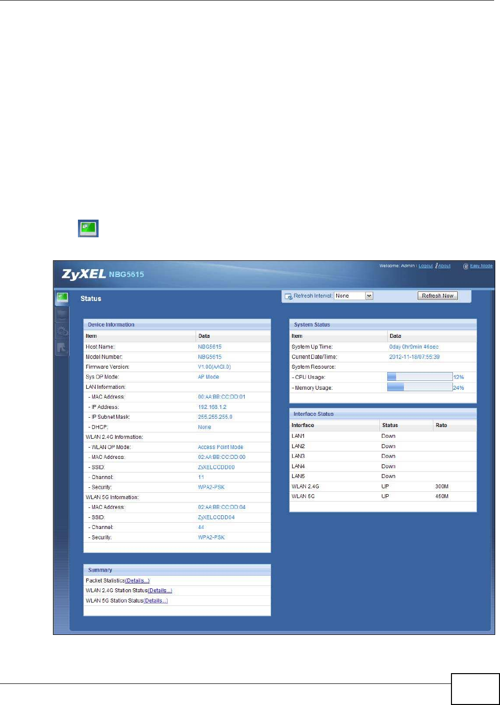
Chapter 8 Access Point Mode
NBG5615 User’s Guide 67
Note: After clicking Login, the Easy Mode appears. Refer to Section on page 45 for the
Easy Mode screens. Change to Expert Mode to see the screens described in the
sections following this.
8.3.3 Configuring your WLAN and Maintenance Settings
The configuration of wireless and maintenance settings in Access Point Mode is the same as for
Router Mode.
•See
Chapter 12 on page 105 for information on the configuring your wireless network.
•See
Chapter 24 on page 193 for information on configuring your Maintenance settings.
8.4 AP Mode Status Screen
Click to open the Status screen.
Figure 41 Status Screen: Access Point Mode

Chapter 8 Access Point Mode
NBG5615 User’s Guide
68
The following table describes the labels shown in the Status screen.
Table 27 Status Screen: Access Point Mode
LABEL DESCRIPTION
Device Information
Host Name This is the System Nam e you enter in the Maintenance > General screen. It is for
identification purposes.
Model Number This is the model name of your device.
Firmware Version This is the firmware version and the date created.
Sys OP Mode This is the device mode (Section 5.1.2 on page 43) to which the NBG5615 is set - AP Mode.
LAN Information
MAC Address This shows the LAN Ethernet adapter MAC Address of your device.
IP Address This shows the LAN port’s IP address.
IP Subnet Mask This shows the LAN port’s subnet mask.
DHCP This shows the LAN port’s DHCP role - Client or None.
WLAN 2.4G Information
WLAN OP Mode This is the device mode (Section 5.1.2 on page 43) to which the NBG5615’s wireless LAN is
set - Access Point Mode.
MAC Address This shows the 2.4GHz wireless adapter MAC Address of your device.
SSID This shows a descriptive name used to identify the NBG5615 in the 2.4GHz wireless LAN.
Channel This shows the channel number which you select manually.
Security This shows the level of wireless security the NBG5615 is using.
WLAN 5G Information
MAC Address This shows the 5GHz wireless adapter MAC Address of your device.
SSID This shows a descriptive name used to identify the NBG5615 in the 5GHz wireless LAN.
Channel This shows the channel number which you select manually.
Security This shows the level of wireless security the NBG5615 is using.
Summary
Packet Statistics Click Details... to go to the Monitor > Packet Statistics screen (Section 10.5 on page
91). Use this screen to view port status and packet specific statistics.
WLAN 2.4G Station
Status Click Details... to go to the Monitor > W LAN 2 .4 G Station Status screen (Section 10.6
on page 92). Use this screen to view the wireless stations that are currently associated to
the NBG5615’s 2.4GHz wireless LAN.
WLAN 5G Station Status Click Details... to go to the Monitor > W LAN 5 G Station Status screen (Section 10.6 on
page 92). Use this screen to view the wireless stations that are currently associated to the
NBG5615’s 5GHz wireless LAN.
System Status
Item This column shows the type of data the NBG5615 is recording.
Data This column shows the actual data recorded by the NBG5615.
System Up Time This is the total time the NBG5615 has been on.
Current Date/Time This field displays your NBG5615’s present date and time.
System Resource
- CPU Usage This displays what percentage of the NBG5615’s processing ability is currently used. When
this percentage is close to 100%, the NBG5615 is running at full load, and the throughput is
not going to improve anymore. If you want some applications to have more throughput, you
should turn off other applications (for example, using bandwidth management.)
- Memory Usage This shows what percentage of the heap memory the NBG5615 is using.
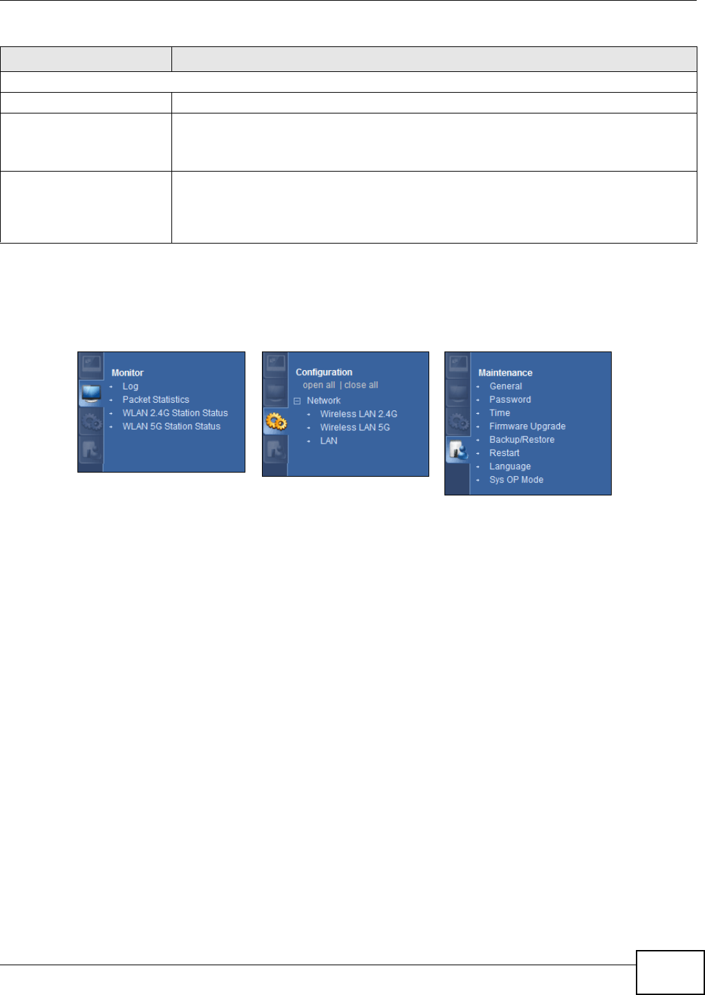
Chapter 8 Access Point Mode
NBG5615 User’s Guide 69
8.4.1 Navigation Panel
Use the menu in the navigation panel to configure NBG5615 features in Access Point Mode.
Figure 42 Menu: Access Point Mode
Refer to Table 26 on page 61 for descriptions of the labels shown in the navigation panel.
8.5 LAN Screen
Use this section to configure your LAN settings while in Access Point Mode.
Click Netw ork > LAN to see the screen below.
Note: If you change the IP address of the NBG5615 in the screen below, you will need to
log into the NBG5615 again using the new IP address.
Interface Status
Interface This displays the NBG5615 port types. The port types are: LAN and W LAN.
Status For the LAN ports, this field displays Dow n (line is down) or Up (line is up or connected).
For the 2.4GHz/5GHz WLAN, it displays Up when the 2.4GHz/5GHz WLAN is enabled or
Dow n when the 2.4G/5G WLAN is disabled.
Rate For the LAN ports, this displays the port speed and duplex setting or N/ A when the line is
disconnected.
For the 2.4GHz/5GHz WLAN, it displays the maximum transmission rate when the 2.4GHz/
5GHz WLAN is enabled and N/ A when the WLAN is disabled.
Table 27 Status Screen: Access Point Mode (continued)
LABEL DESCRIPTION
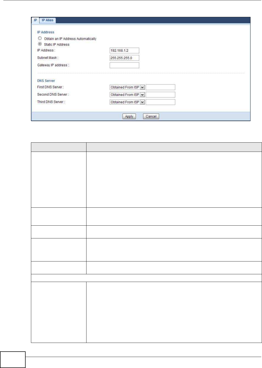
Chapter 8 Access Point Mode
NBG5615 User’s Guide
70
Figure 43 Network > LAN > IP
The table below describes the labels in the screen.
Table 28 Network > LAN > IP
LABEL DESCRIPTION
Obtain an IP Address
Automatically
When you enable this, the NBG5615 gets its IP address from the network’s DHCP
server (for example, your ISP). Users connected to the NBG5615 can now access
the network (i.e., the Internet if the IP address is given by the ISP).
The Web Configurator may no longer be accessible unless you know the IP address
assigned by the DHCP server to the NBG5615. You need to reset the NBG5615 to
be able to access the Web Configurator again (see Section 24.7 on page 198 for
details on how to reset the NBG5615).
Also when you select this, you cannot enter an IP address for your NBG5615 in the
field below.
Static IP Address Click this if you want to specify the IP address of your NBG5615. Or if your ISP or
network administrator gave you a static IP address to access the network or the
Internet.
IP Address Type the IP address in dotted decimal notation. The default setting is 192.168.1.2.
If you change the IP address you will have to log in again with the new IP address.
Subnet Mask The subnet mask specifies the network number portion of an IP address. Your
NBG5615 will automatically calculate the subnet mask based on the IP address that
you assign. Unless you are implementing subnetting, use the subnet mask
computed by the NBG5615.
Gateway IP Address Enter a Gatew ay I P Address (if your ISP or network administrator gave you one)
in this field.
DNS Assignment
First DNS Server
Second DNS Server
Third DNS Server
Select Obtained From I SP if your ISP dynamically assigns DNS server information
(and the NBG5615's WAN IP address). The field to the right displays the (read-
only) DNS server IP address that the ISP assigns.
Select User-Defined if you have the IP address of a DNS server. Enter the DNS
server's IP address in the field to the right. If you chose User- Defined, but leave
the IP address set to 0.0.0.0, User- Defined changes to None after you click
Apply. If you set a second choice to User- Defined, and enter the same IP
address, the second User-Defined changes to None after you click Apply.
Select None if you do not want to configure DNS servers. If you do not configure a
DNS server, you must know the IP address of a computer in order to access it.

Chapter 8 Access Point Mode
NBG5615 User’s Guide 71
Apply Click Apply to save your changes to the NBG5615.
Cancel Click Cancel to reload the previous configuration for this screen.
Table 28 Network > LAN > IP (continued)
LABEL DESCRIPTION

Chapter 8 Access Point Mode
NBG5615 User’s Guide
72

NBG5615 User’s Guide 73
CHAPTER 9
Tutorials
9.1 Overview
This chapter provides tutorials for setting up your NBG5615.
•Set Up a Wireless Network with WPS
•Configure Wireless Security without WPS
•Using Multiple SSIDs on the NBG5615
•Automatically Connecting to a USB Printer
9.2 Set Up a Wireless Network with WPS
This section gives you an example of how to set up wireless network using WPS. This example uses
the NBG5615 as the AP and NWD210N as the wireless client which connects to a notebook.
Note: The wireless client must be a WPS-aware device (for example, a WPS USB adapter
or PCI card).
There are two WPS methods for creating a secure connection. This tutorial shows you how to do
both.
•Push Button Configuration ( PBC) - create a secure wireless network simply by pressing a
button. See Section 9.2.1 on page 73.This is the easier method.
•PI N Configuration - create a secure wireless network simply by entering a wireless client's PIN
(Personal Identification Number) in the NBG5615’s interface. See Section 9.2.2 on page 74. This
is the more secure method, since one device can authenticate the other.
9.2.1 Push Button Configuration (PBC)
1Make sure that your NBG5615 is turned on. Make sure the W I FI button (at the back panel of the
NBG5615) is pushed in, and that the device is placed within range of your notebook.
2Make sure that you have installed the wireless client (this example uses the NWD210N) driver and
utility in your notebook.
3In the wireless client utility, find the WPS settings. Enable WPS and press the WPS button (Start or
W PS button)
4Log into NBG5615’s Web Configurator and press the Push Button in the Configuration >
Netw ork > W ireless LAN 2 .4 G > W PS Station screen.
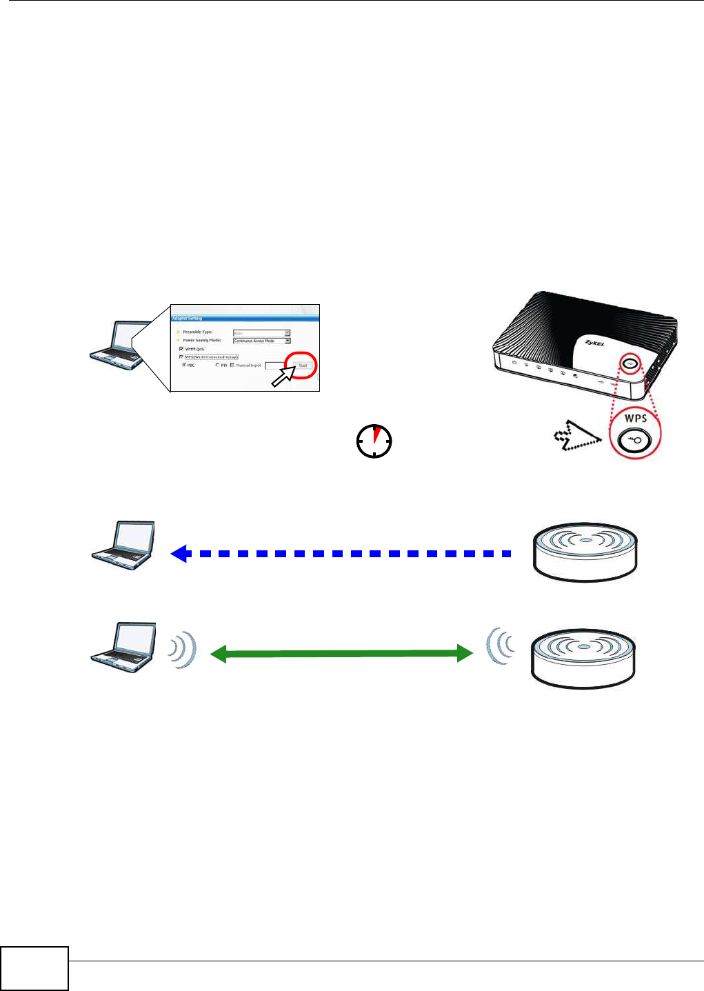
Chapter 9 Tutorials
NBG5615 User’s Guide
74
Note: Your NBG5615 has a WPS button located on its panel, as well as a WPS button in its
configuration utility. Both buttons have exactly the same function; you can use one
or the other.
Note: It doesn’t matter which button is pressed first. You must press the second button
within two minutes of pressing the first one.
The NBG5615 sends the proper configuration settings to the wireless client. This may take up to
two minutes. Then the wireless client is able to communicate with the NBG5615 securely.
The following figure shows you an example to set up wireless network and security by pressing a
button on both NBG5615 and wireless client (the NWD210N in this example).
Figure 44 Example WPS Process: PBC Method
9.2.2 PIN Configuration
When you use the PIN configuration method, you need to use both NBG5615’s configuration
interface and the client’s utilities.
1Launch your wireless client’s configuration utility. Go to the WPS settings and select the PIN method
to get a PIN number.
2Enter the PIN number to the PI N field in the Configuration > Netw ork > W ireless LAN 2 .4 G >
W PS Station screen on the NBG5615.
Wireless Client Access Point
SECURITY INFO
COMMUNICATION
WITHIN 2 MINUTES
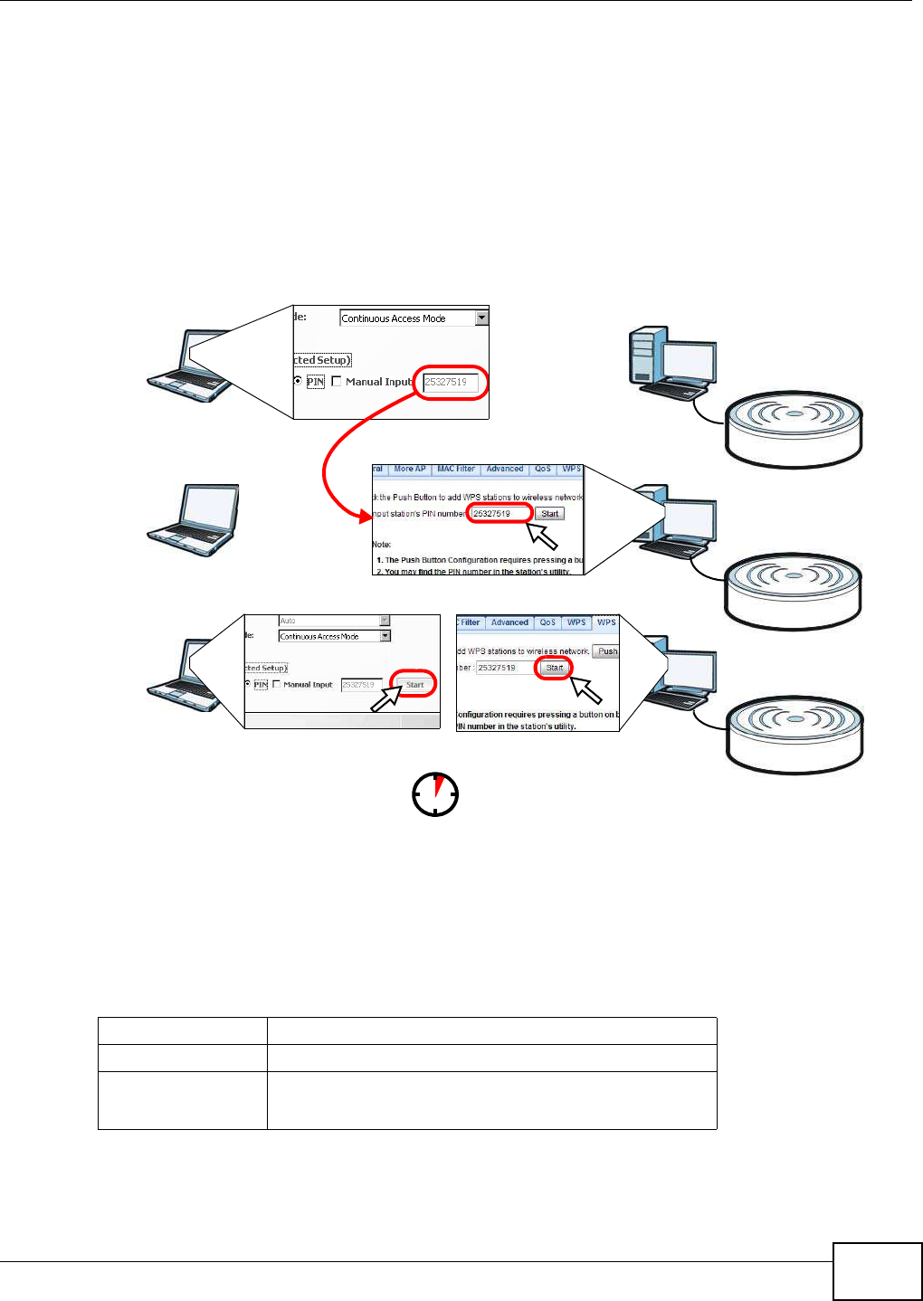
Chapter 9 Tutorials
NBG5615 User’s Guide 75
3Click Start buttons (or button next to the PIN field) on both the wireless client utility screen and the
NBG5615’s WPS Station screen within two minutes.
The NBG5615 authenticates the wireless client and sends the proper configuration settings to the
wireless client. This may take up to two minutes. Then the wireless client is able to communicate
with the NBG5615 securely.
The following figure shows you the example to set up wireless network and security on NBG5615
and wireless client (ex. NWD210N in this example) by using PIN method.
Figure 45 Example WPS Process: PIN Method
9.3 Configure Wireless Security without WPS
This example shows you how to configure wireless security settings with the following parameters
on your NBG5615.
Follow the steps below to configure the wireless settings on your NBG5615.
WITHIN 2 MINUTES
Wireless Client
Access Point
SSI D SSID_Example3
Channel 6
Security WPA2-PSK
(Pre-Shared Key: ThisismyWPA-PSKpre-sharedkey)
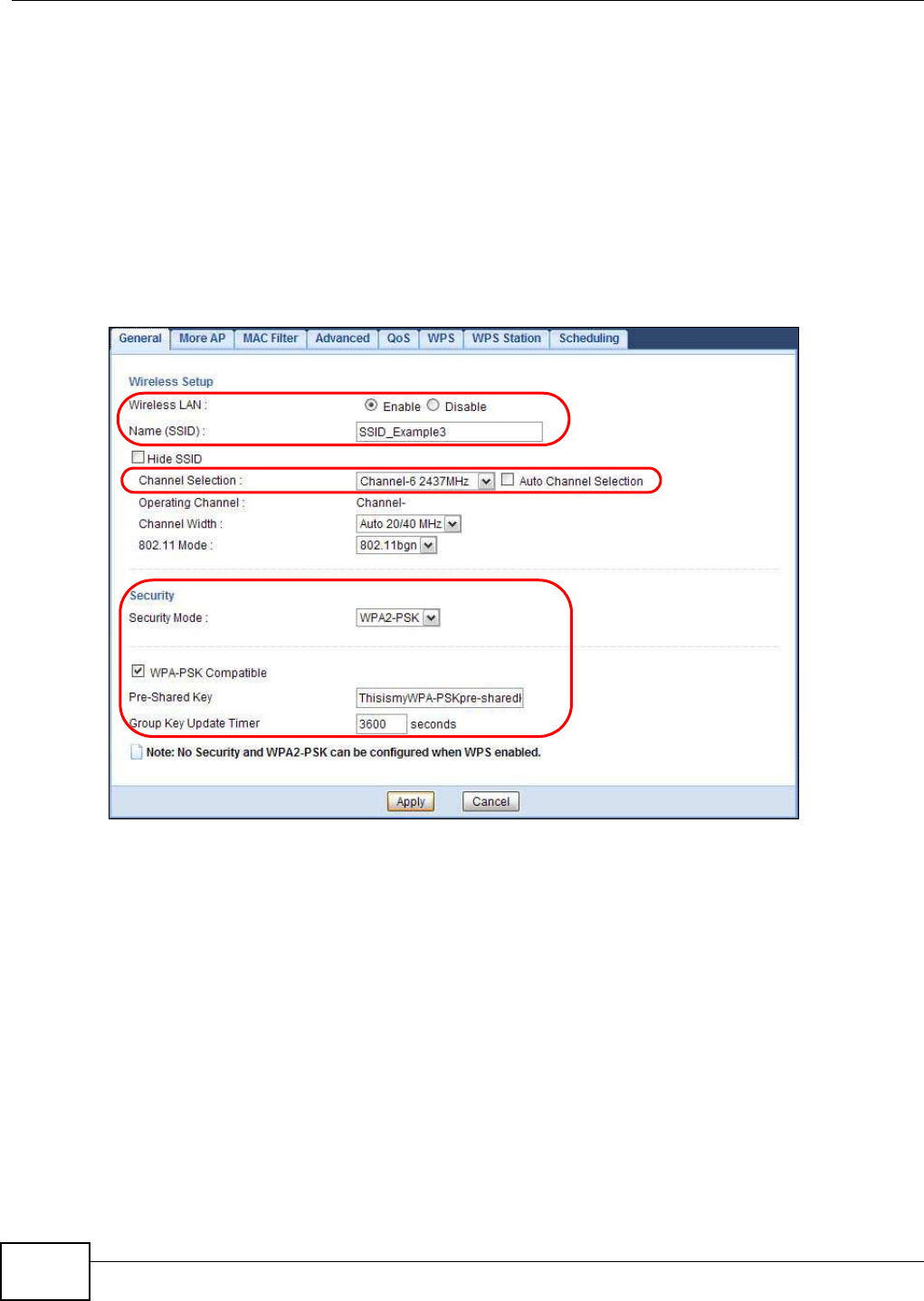
Chapter 9 Tutorials
NBG5615 User’s Guide
76
The instructions require that your hardware is connected (see the Quick Start Guide) and you are
logged into the Web Configurator through your LAN connection (see Section 4.2 on page 39).
1Make sure the W I FI switch (at the back panel of the NBG5615) is set to ON.
2Open the Configuration > Netw ork > W ireless LAN 2 .4 G > General screen in the AP’s Web
Configurator.
3Confirm that the wireless LAN is enabled on the NBG5615.
4Enter SSI D_ Exam ple3 as the SSID and select Channel- 06 as the channel. Set security mode to
W PA2 -PSK and enter Thisism yW PA- PSKpre- sharedkey in the Pre-Shared Key field. Click
Apply.
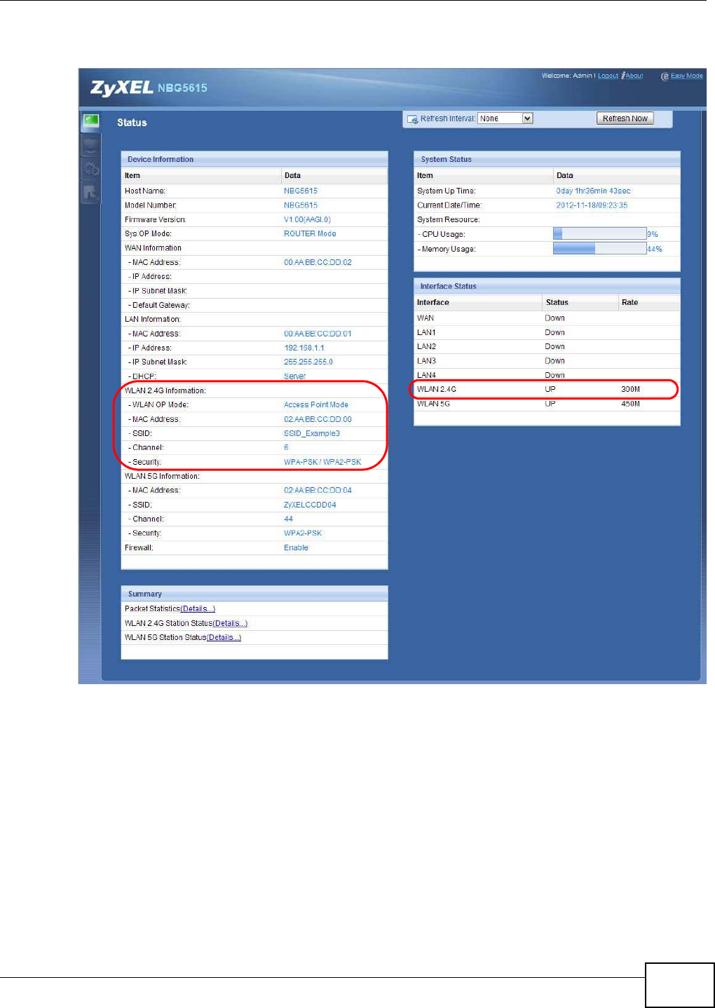
Chapter 9 Tutorials
NBG5615 User’s Guide 77
5Open the Status screen. Verify your wireless and wireless security settings under Device
I nform at ion and check if the WLAN connection is up under I nterface Status.
9.3.1 Configure Your Notebook
Note: We use the ZyXEL NWD2205 wireless adapter utility screens as an example for the
wireless client. The screens may vary for different models.
1The NBG5615 supports IEEE 802.11a, IEEE 802.11b, IEEE 802.11g and IEEE 802.11n wireless
clients. Make sure that your notebook or computer’s wireless adapter supports one of these
standards.
2Wireless adapters come with software sometimes called a “utility” that you install on your
computer. See your wireless adapter’s User’s Guide for information on how to do that.
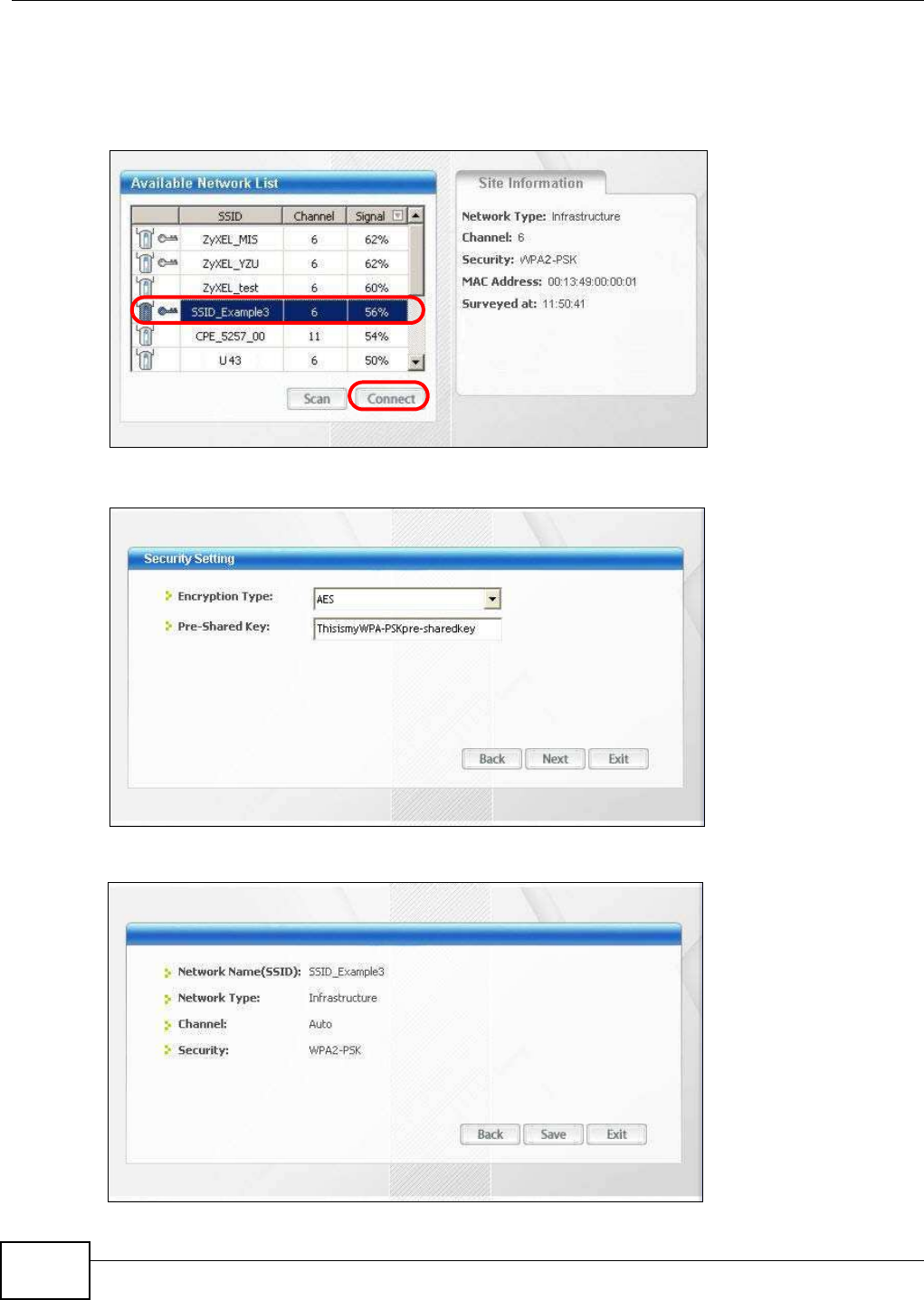
Chapter 9 Tutorials
NBG5615 User’s Guide
78
3After you’ve installed the utility, open it. If you cannot see your utility’s icon on your screen, go to
Start > Program s and click on your utility in the list of programs that appears. The utility displays
a list of APs within range, as shown in the example screen below.
4Select SSID_Example3 and click Connect.
5Select AES and type the security key in the following screen. Click Next.
6The Confirm Save window appears. Check your settings and click Save to continue.
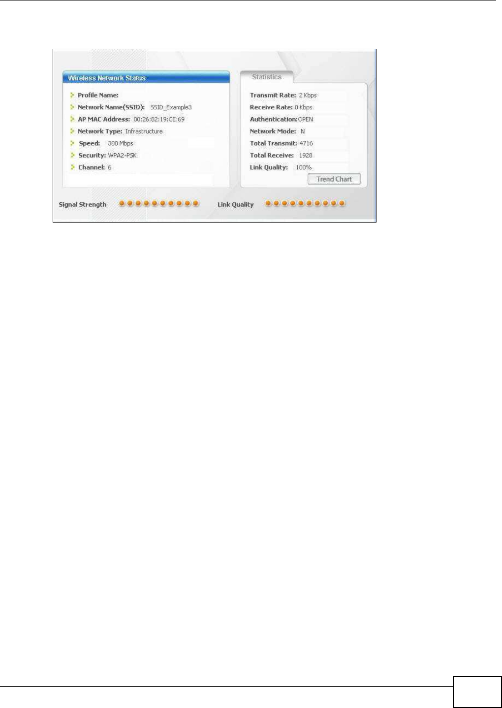
Chapter 9 Tutorials
NBG5615 User’s Guide 79
7Check the status of your wireless connection in the screen below. If your wireless connection is
weak or you have no connection, see the Troubleshooting section of this User’s Guide.
If your connection is successful, open your Internet browser and enter http://www.zyxel.com or the
URL of any other web site in the address bar. If you are able to access the web site, your wireless
connection is successfully configured.
9.4 Using Multiple SSIDs on the NBG5615
You can configure more than one SSID on a NBG5615. See Section 12.4 on page 118.
This allows you to configure multiple independent wireless networks on the NBG5615 as if there
were multiple APs (virtual APs). Each virtual AP has its own SSID, wireless security type and MAC
filtering settings. That is, each SSID on the NBG5615 represents a different access point/wireless
network to wireless clients in the network.
Clients can associate only with the SSIDs for which they have the correct security settings. Clients
using different SSIDs can access the Internet and the wired network behind the NBG5615 (such as
a printer).
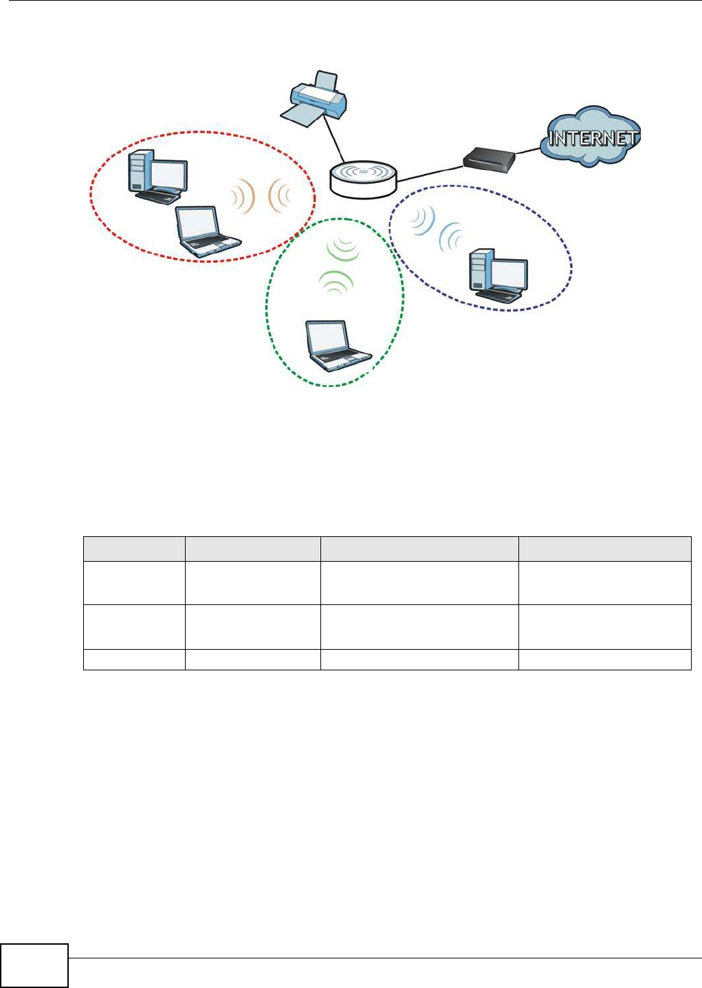
Chapter 9 Tutorials
NBG5615 User’s Guide
80
For example, you may set up three wireless networks (A, B and C) in your office. A is for workers,
B is for guests and C is specific to a VoIP device in the meeting room.
9.4.1 Configuring Security Settings of Multiple SSIDs
The NBG5615 is in router mode by default.
This example shows you how to configure the SSIDs with the following parameters on your
NBG5615 (in router mode).
1Connect your computer to the LAN port of the NBG5615 using an Ethernet cable.
2The default IP address of the NBG5615 in router mode is “192.168.1.1”. In this case, your
computer must have an IP address in the range between “192.168.1.2” and “192.168.1.254”.
3Click Start > Run on your computer in Windows. Type “cmd” in the dialog box. Enter “ipconfig” to
show your computer’s IP address. If your computer’s IP address is not in the correct range then see
Appendix B on page 221 for information on changing your computer’s IP address.
4After you’ve set your computer’s IP address, open a web browser such as Internet Explorer and
type “http://192.168.1.1” as the web address in your web browser.
5Enter “1234” (default) as the password and click Login.
A
B
C
SSI D_Guest
SSI D_ W orker
SSI D_VoI P
SSID SECURITY TYPE KEY MAC FILTERING
SSID_Worker WPA2-PSK
WPA Compatible
DoNotStealMyWirelessNetwork Disable
SSID_VoIP WPA-PSK VoIPOnly12345678 Allow
00:A0:C5:01:23:45
SSID_Guest WPA-PSK keyexample123 Disable
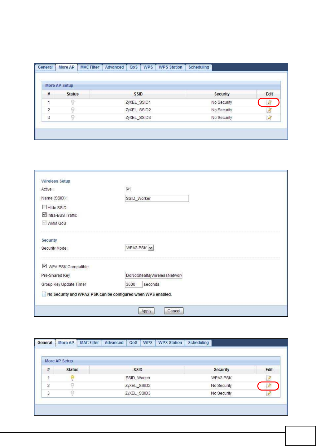
Chapter 9 Tutorials
NBG5615 User’s Guide 81
6Type a new password and retype it to confirm, then click Apply. Otherwise, click I gnore.
7The Easy Mode appears. Click Expert Mode in the navigation panel.
8Go to Configuration > Netw ork > W ireless LAN 2 .4 G > More AP. Click the Edit icon of the first
entry to configure wireless and security settings for SSI D_ W orker.
9Configure the screen as follows. In this example, you enable I ntra-BSS Traffic for SSI D_W orker
to allow wireless clients in the same wireless network to communicate with each other. Click Apply.
10 Click the Edit icon of the second entry to configure wireless and security settings for SSI D_VoI P.
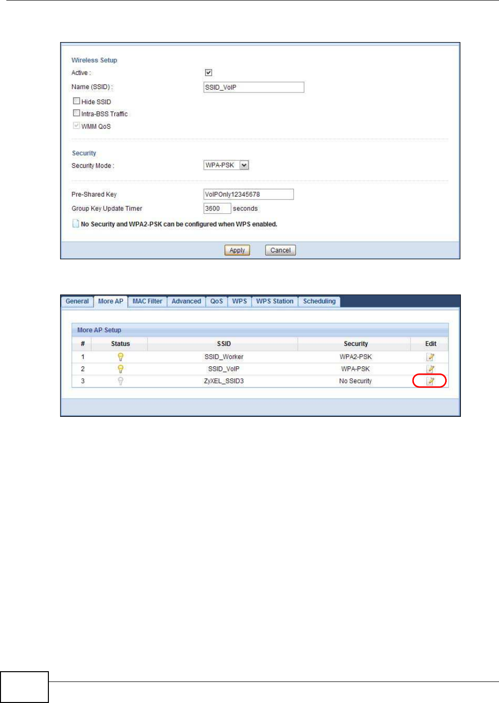
Chapter 9 Tutorials
NBG5615 User’s Guide
82
11 Configure the screen as follows. You do not enable I ntra- BSS Traffic for SSI D_ VoI P. Click Apply.
12 Click the Edit icon of the third entry to configure wireless and security settings for SSI D_Guest.
13 Configure the screen as follows. In this example, you enable I ntra-BSS Traffic for SSI D_ Guest to
allow wireless clients in the same wireless network to communicate with each other. Select Enable
Guest W LAN to allow clients to access the Internet only. Click Apply.
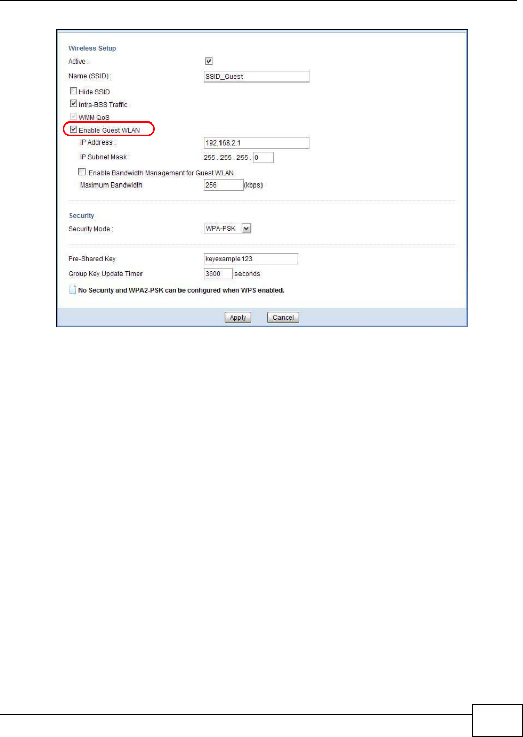
Chapter 9 Tutorials
NBG5615 User’s Guide 83
14 Click the MAC Filter tab to configure MAC filtering for the SSI D_ VoI P wireless network. Select
SSI D_VoI P from the SSI D Select drop-down list, enable MAC address filtering and set the Filter
Action to Allow . Enter the VoIP device’s MAC address in the Mac Address field and click Apply to
allow only the VoIP device to associate with the NBG5615 using this SSID.
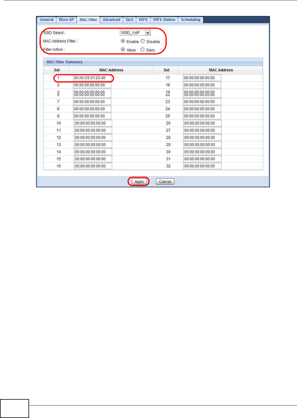
Chapter 9 Tutorials
NBG5615 User’s Guide
84
9.5 Automatically Connecting to a USB Printer
Your computer can connect to a shared USB printer by using the ZyXEL NetUSB Share Center
Utility. This tutorial shows you how to set your computer to automatically connect to a shared USB
printer over your NBG5615 network each time you log into your computer.
1Install the ZyXEL NetUSB Share Center Utility to your computer which should be connected to the
NBG5615’s network. See Chapter 2 on page 22 for details on the installation.
2Connect a USB printer to one of the USB ports of the NBG5615.
3Open the ZyXEL NetUSB Sharing Center Utility on your computer. The name of the USB printer
automatically shows in the Utility screen.
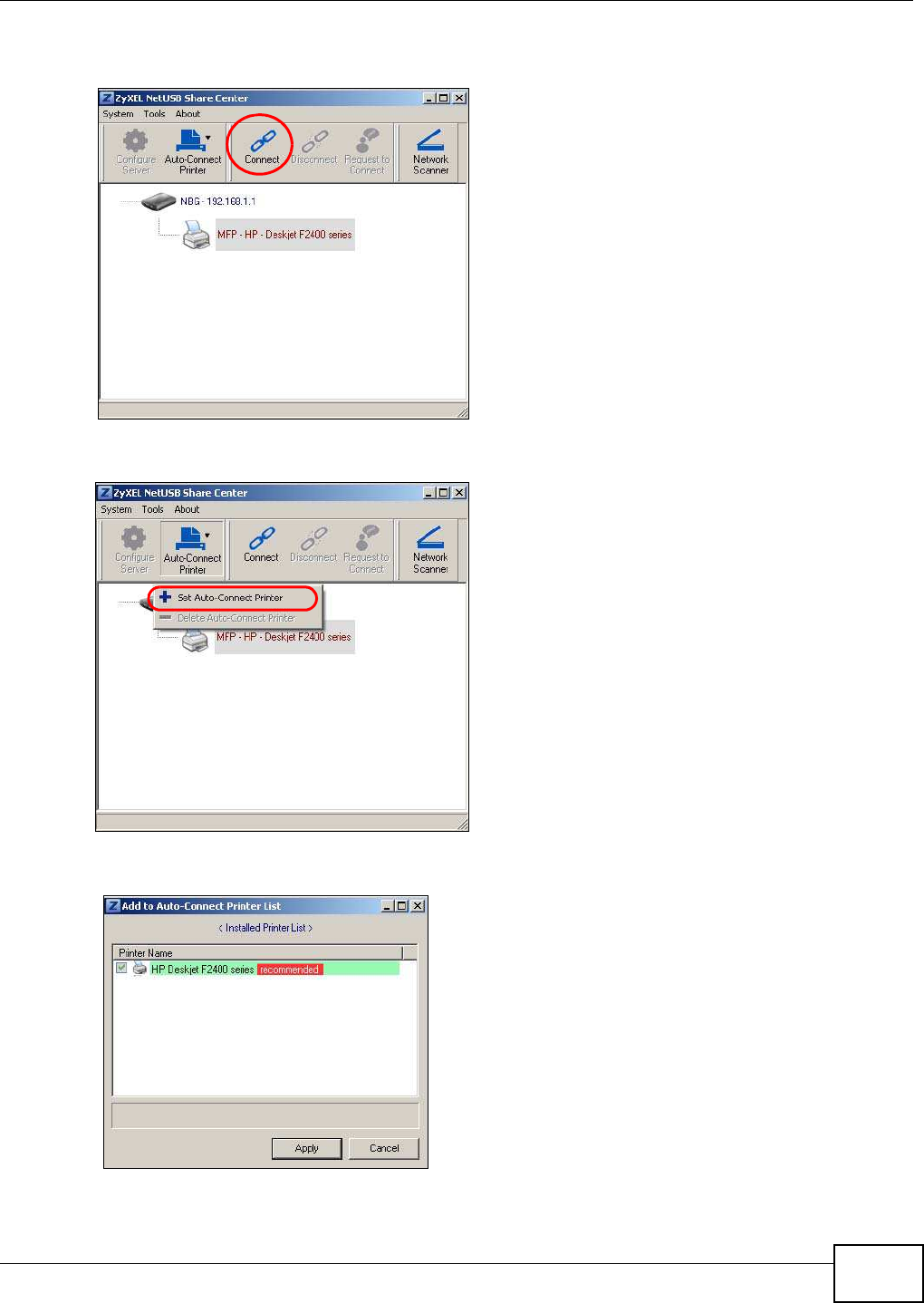
Chapter 9 Tutorials
NBG5615 User’s Guide 85
4Click on the printer name. Then click Connect. Your computer will search for the printer driver. You
may be prompted to install the driver. Follow the driver’s installation steps to finish installing.
5Click the Auto-Connect Printer menu and select Set Auto-Connect Printer from the menu.
6Select the USB printer you want to connect to and click Apply.

Chapter 9 Tutorials
NBG5615 User’s Guide
86
7Now your computer can automatically connect to this shared USB printer over your NBG5615
network each time you log into your computer. The printer will be automatically added to your
printer list.
8The Utility supports one connection to the NBG5615’s USB device at a time. If more than one
computer is using the printer and are all auto-connected to the USB device, the second computer
automatically starts printing after the first computer finishes its printing task.

87
PART II
Technical Reference

88
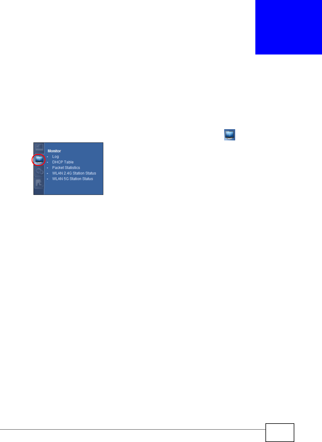
NBG5615 User’s Guide 89
CHAPTER 10
Monitor
10.1 Overview
This chapter discusses read-only information related to the device state of the NBG5615.
To access the Monitor screens, go to Expert Mode after login, then click .
You can also click the links in the Sum m ary table of the Status screen to view the packets sent/
received as well as the status of clients connected to the NBG5615.
10.2 What You Can Do
•Use the Log screen to see the logs for the activity on the NBG5615 (Section 10.3 on page 89).
•Use the DHCP Table screen to view information related to your DHCP status (Section 10.4 on
page 90).
•use the Packet Statistics screen to view port status, packet specific statistics, the "system up
time" and so on (Section 10.5 on page 91).
•Use the W LAN 2 .4G/ 5G Station Status screen to view the wireless stations that are currently
associated to the NBG5615 (Section 10.6 on page 92).
10.3 The Log Screen
The Web Configurator allows you to look at all of the NBG5615’s logs in one location.
10.3.1 View Log
Use the View Log screen to see the logged messages for the NBG5615. The log wraps around and
deletes the old entries after it fills. Select what logs you want to see from the Display drop list. The
log choices depend on your settings in the Log Setting screen. Click Refresh to renew the log
screen. Click Clear Log to delete all the logs.
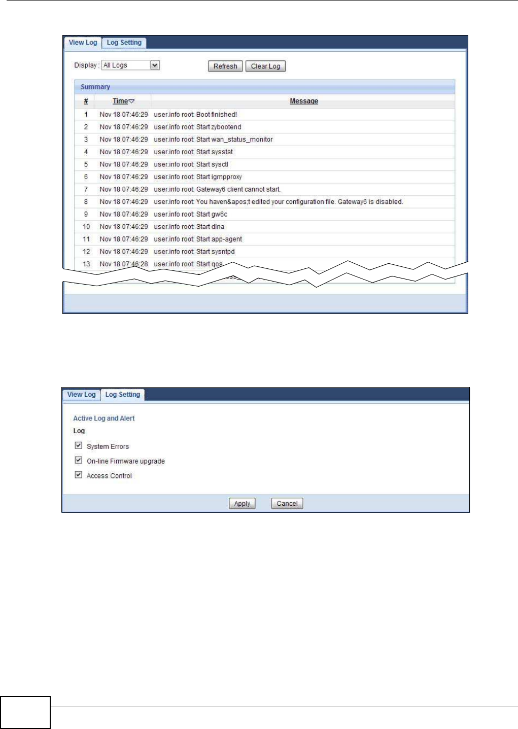
Chapter 10 Monitor
NBG5615 User’s Guide
90
Figure 46 View Log
You can configure which logs to display in the View Log screen. Go to the Log Setting screen and
select the logs you wish to display. Click Apply to save your settings. Click Cancel to start the
screen afresh.
Figure 47 Log Settings
10.4 DHCP Table
DHCP (Dynamic Host Configuration Protocol, RFC 2131 and RFC 2132) allows individual clients to
obtain TCP/IP configuration at start-up from a server. You can configure the NBG5615’s LAN as a
DHCP server or disable it. When configured as a server, the NBG5615 provides the TCP/IP
configuration for the clients. If DHCP service is disabled, you must have another DHCP server on
that network, or else the computer must be manually configured.
Click Monitor > DHCP Table or Configuration > Netw ork > DHCP Server > Client List. Read-
only information here relates to your DHCP status. The DHCP table shows current DHCP client
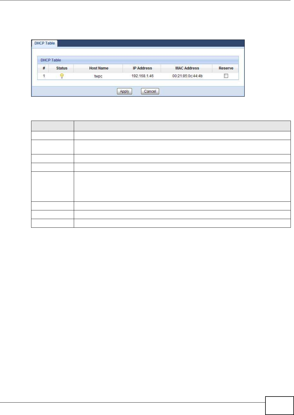
Chapter 10 Monitor
NBG5615 User’s Guide 91
information (including MAC Address, and I P Address) of all network clients using the NBG5615’s
DHCP server.
Figure 48 Monitor > DHCP Table
The following table describes the labels in this screen.
10.5 Packet Statistics
Click Monitor > Packet Statistics or the Packet Statistics ( Details...) hyperlink in the Status
screen. Read-only information here includes port status, packet specific statistics and the "system
up time". The Poll I nterval( s) field is configurable and is used for refreshing the screen.
Table 29 Monitor > DHCP Table
LABEL DESCRIPTION
# This is the index number of the host computer.
Status This field displays whether the connection to the host computer is up (a yellow bulb) or
down (a gray bulb).
Host Name This field displays the computer host name.
IP Address This field displays the IP address relative to the # field listed above.
MAC Address This field shows the MAC address of the computer with the name in the Host Nam e field.
Every Ethernet device has a unique MAC (Media Access Control) address which uniquely
identifies a device. The MAC address is assigned at the factory and consists of six pairs of
hexadecimal characters, for example, 00:A0:C5:00:00:02.
Reserve Select this if you want to reserve the IP address for this specific MAC address.
Apply Click Apply to save your changes back to the NBG5615.
Cancel Click Cancel to reload the previous configuration for this screen.
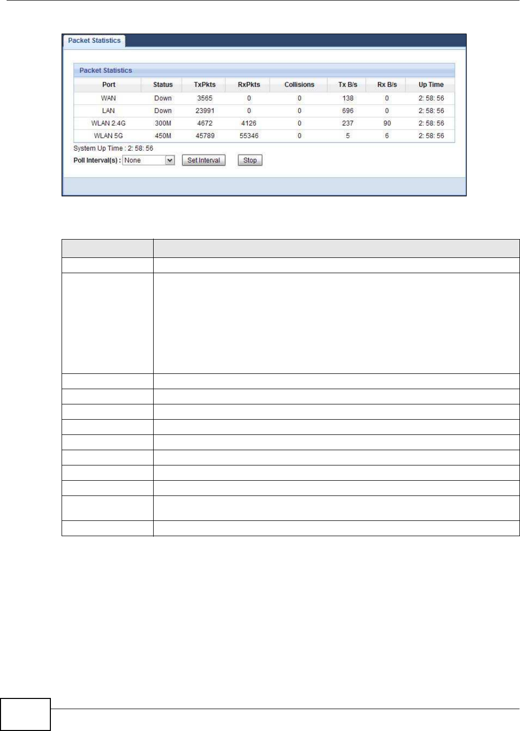
Chapter 10 Monitor
NBG5615 User’s Guide
92
Figure 49 Monitor > Packet Statistics
The following table describes the labels in this screen.
10.6 WLAN Station Status
Click Monitor > W LAN 2 .4 G/ 5G Station Status or the W LAN 2 .4 G/ 5G Station Status
( Details...) hyperlink in the Status screen. View the wireless stations that are currently associated
to the NBG5615’s 2.4GHz or 5GHz wireless network in the Association List. Association means
that a wireless client (for example, your network or computer with a wireless network card) has
connected successfully to the AP (or wireless router) using the same SSID, channel and security
settings.
Table 30 Monitor > Packet Statistics
LABEL DESCRIPTION
Port This is the NBG5615’s interface type.
Status For the LAN ports, this displays the port speed and duplex setting or Dow n when the
line is disconnected.
For the WAN port, it displays the port speed and duplex setting if you’re using Ethernet
encapsulation and I dle (line (ppp) idle), Dial (starting to trigger a call) and Drop
(dropping a call) if you're using PPPoE or PPTP encapsulation. This field displays Dow n
when the line is disconnected.
For the 2.4GHz or 5GHz WLAN, it displays the maximum transmission rate when the
WLAN is enabled and Dow n when the WLAN is disabled.
TxPkts This is the number of transmitted packets on this port.
RxPkts This is the number of received packets on this port.
Collisions This is the number of collisions on this port.
Tx B/s This displays the transmission speed in bytes per second on this port.
Rx B/s This displays the reception speed in bytes per second on this port.
Up Time This is the total time the NBG5615 has been for each session.
System Up Time This is the total time the NBG5615 has been on.
Poll Interval(s) Enter the time interval in seconds for refreshing statistics in this field.
Set Interval Click this button to apply the new poll interval you entered in the Poll I nterval( s)
field.
Stop Click Stop to stop refreshing statistics.
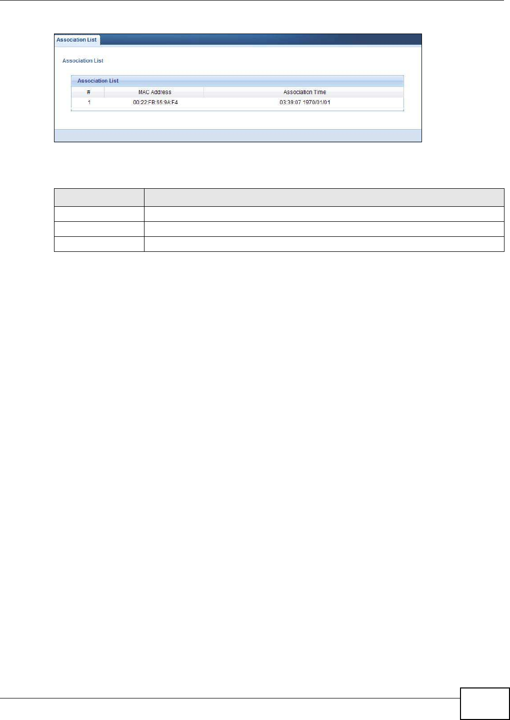
Chapter 10 Monitor
NBG5615 User’s Guide 93
Figure 50 Monitor > WLAN Station Status
The following table describes the labels in this screen.
Table 31 Monitor > WLAN Station Status
LABEL DESCRIPTION
# This is the index number of an associated wireless station.
MAC Address This field displays the MAC address of an associated wireless station.
Association Time This field displays the time a wireless station first associated with the NBG5615’s WLAN.

Chapter 10 Monitor
NBG5615 User’s Guide
94
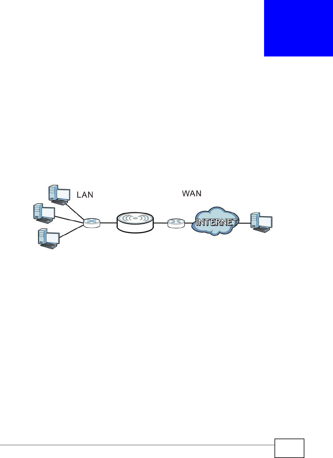
NBG5615 User’s Guide 95
CHAPTER 11
WAN
11.1 Overview
This chapter discusses the NBG5615’s W AN screens. Use these screens to configure your NBG5615
for Internet access.
A WAN (Wide Area Network) connection is an outside connection to another network or the
Internet. It connects your private networks such as a LAN (Local Area Network) and other
networks, so that a computer in one location can communicate with computers in other locations.
Figure 51 LAN and WAN
11.2 What You Can Do
•Use the I nternet Connection screen to enter your ISP information and set how the computer
acquires its IP, DNS and WAN MAC addresses (Section 11.4 on page 97).
•Use the Advanced screen to enable multicasting, configure Windows networking and bridge
(Section 11.5 on page 104).
11.3 What You Need To Know
The information in this section can help you configure the screens for your WAN connection, as well
as enable/disable some advanced features of your NBG5615.

Chapter 11 WAN
NBG5615 User’s Guide
96
11.3.1 Configuring Your Internet Connection
Encapsulation Method
Encapsulation is used to include data from an upper layer protocol into a lower layer protocol. To set
up a WAN connection to the Internet, you need to use the same encapsulation method used by your
ISP (Internet Service Provider). If your ISP offers a dial-up Internet connection using PPPoE (PPP
over Ethernet) or PPTP (Point-to-Point Tunneling Protocol), they should also provide a username
and password (and service name) for user authentication.
WAN IP Address
The WAN IP address is an IP address for the NBG5615, which makes it accessible from an outside
network. It is used by the NBG5615 to communicate with other devices in other networks. It can be
static (fixed) or dynamically assigned by the ISP each time the NBG5615 tries to access the
Internet.
If your ISP assigns you a static WAN IP address, they should also assign you the subnet mask and
DNS server IP address(es) (and a gateway IP address if you use the Ethernet or ENET ENCAP
encapsulation method).
DNS Server Address Assignment
Use Domain Name System (DNS) to map a domain name to its corresponding IP address and vice
versa, for instance, the IP address of www.zyxel.com is 204.217.0.2. The DNS server is extremely
important because without it, you must know the IP address of a computer before you can access
it.
The NBG5615 can get the DNS server addresses in the following ways.
1The ISP tells you the DNS server addresses, usually in the form of an information sheet, when you
sign up. If your ISP gives you DNS server addresses, manually enter them in the DNS server fields.
2If your ISP dynamically assigns the DNS server IP addresses (along with the NBG5615’s WAN IP
address), set the DNS server fields to get the DNS server address from the ISP.
WAN MAC Address
The MAC address screen allows users to configure the WAN port's MAC address by either using the
factory default or cloning the MAC address from a computer on your LAN. Choose Factory Default
to select the factory assigned default MAC Address.
Otherwise, click Clone the com puter's MAC address - I P Address and enter the IP address of
the computer on the LAN whose MAC you are cloning. Once it is successfully configured, the
address will be copied to configuration file. It is recommended that you clone the MAC address prior
to hooking up the WAN Port.
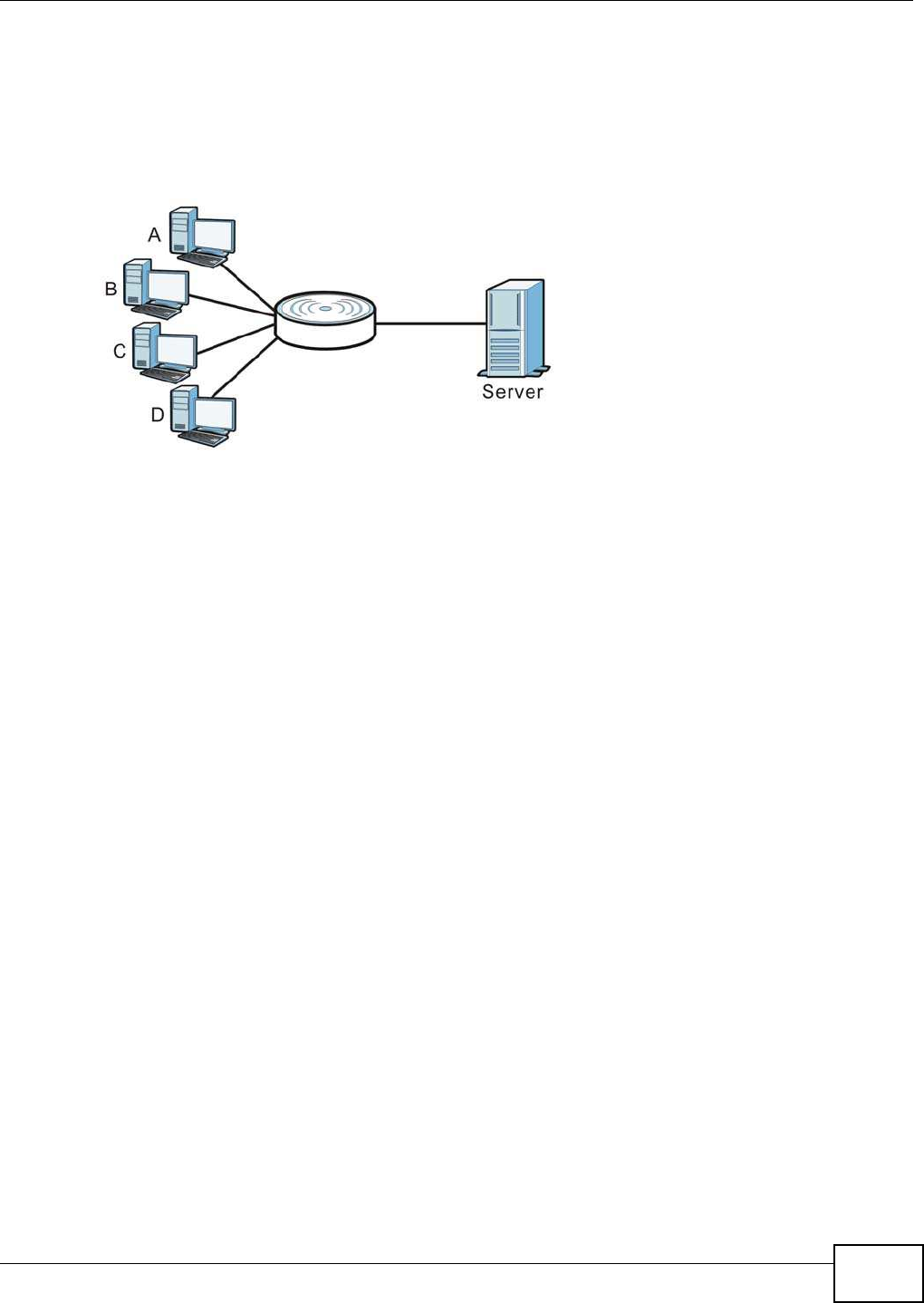
Chapter 11 WAN
NBG5615 User’s Guide 97
Multicast
Traditionally, IP packets are transmitted in one of either two ways - Unicast (1 sender - 1 recipient)
or Broadcast (1 sender - everybody on the network). Multicast delivers IP packets to a group of
hosts on the network - not everybody and not just 1.
Figure 52 Multicast Example
In the multicast example above, systems A and D comprise one multicast group. In multicasting,
the server only needs to send one data stream and this is delivered to systems A and D.
IGMP (Internet Group Multicast Protocol) is a network-layer protocol used to establish membership
in a multicast group - it is not used to carry user data. The NBG5615 supports both IGMP version 1
(I GMP-v1) and IGMP version 2 (I GMP- v2).
At start up, the NBG5615 queries all directly connected networks to gather group membership.
After that, the NBG5615 periodically updates this information. IP multicasting can be enabled/
disabled on the NBG5615 WAN interface in the Web Configurator (W AN). Select None to disable IP
multicasting on these interfaces.
11.4 Internet Connection
Use this screen to change your NBG5615’s Internet access settings. Click Netw ork > W AN from
the Configuration menu. The screen differs according to the encapsulation you choose.
11.4.1 IPoE Encapsulation
This screen displays when you select I PoE encapsulation.
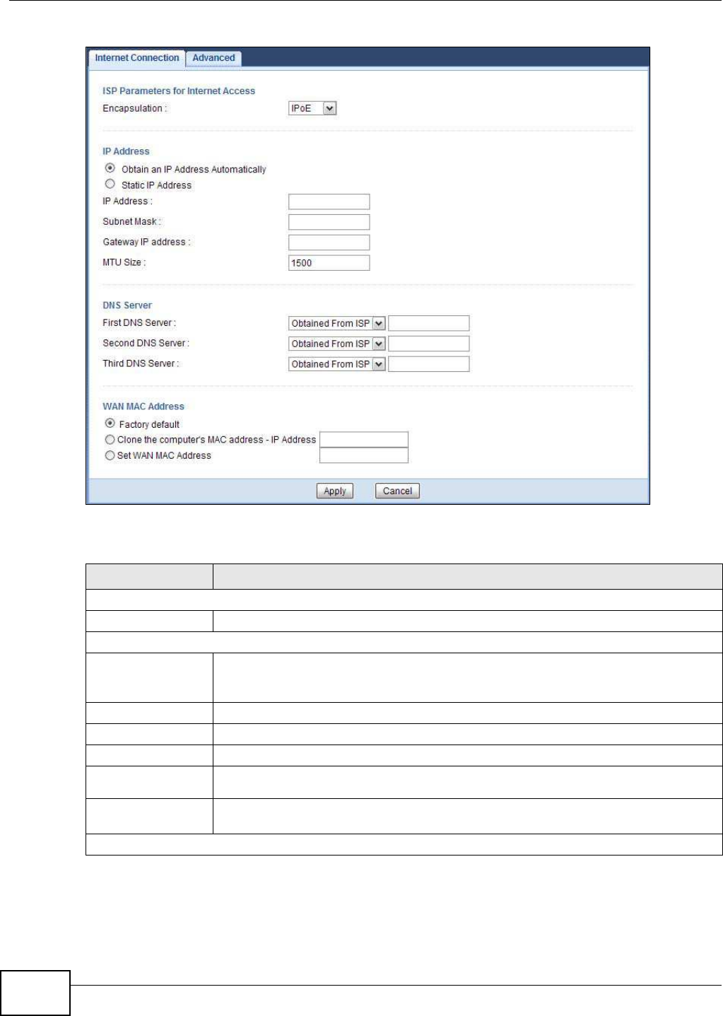
Chapter 11 WAN
NBG5615 User’s Guide
98
Figure 53 Network > WAN > Internet Connection: IPoE Encapsulation
The following table describes the labels in this screen.
Table 32 Network > WAN > Internet Connection: IPoE Encapsulation
LABEL DESCRIPTION
ISP Parameters for Internet Access
Encapsulation You must choose the I PoE option when the WAN port is used as a regular Ethernet.
IP Address
Obtain an IP
Address
Automatically
Select this option If your ISP did not assign you a fixed IP address. This is the default
selection.
Static IP Address Select this option If the ISP assigned a fixed IP address.
IP Address Enter your WAN IP address in this field if you selected Static I P Address.
Subnet Mask Enter the Subnet Mask in this field.
Gateway IP
Address Enter a Gatew ay I P Address (if your ISP gave you one) in this field.
MTU Size Enter the MTU (Maximum Transmission Unit) size for each packet. If a larger packet
arrives, the NBG5615 divides it into smaller fragments.
DNS Server

Chapter 11 WAN
NBG5615 User’s Guide 99
11.4.2 PPPoE Encapsulation
The NBG5615 supports PPPoE (Point-to-Point Protocol over Ethernet). PPPoE is an IETF standard
(RFC 2516) specifying how a personal computer (PC) interacts with a broadband modem (DSL,
cable, wireless, etc.) connection. The PPP over Ethernet option is for a dial-up connection using
PPPoE.
For the service provider, PPPoE offers an access and authentication method that works with existing
access control systems (for example Radius).
One of the benefits of PPPoE is the ability to let you access one of multiple network services, a
function known as dynamic service selection. This enables the service provider to easily create and
offer new IP services for individuals.
Operationally, PPPoE saves significant effort for both you and the ISP or carrier, as it requires no
specific configuration of the broadband modem at the customer site.
By implementing PPPoE directly on the NBG5615 (rather than individual computers), the computers
on the LAN do not need PPPoE software installed, since the NBG5615 does that part of the task.
Furthermore, with NAT, all of the LANs’ computers will have access.
First DNS Server
Second DNS Server
Third DNS Server
Select Obtained From I SP if your ISP dynamically assigns DNS server information
(and the NBG5615's WAN IP address). The field to the right displays the (read-only)
DNS server IP address that the ISP assigns.
Select User-Defined if you have the IP address of a DNS server. Enter the DNS
server's IP address in the field to the right. If you chose User-Defined, but leave the IP
address set to 0.0.0.0, User-Defined changes to None after you click Apply. If you
set a second choice to User- Defined, and enter the same IP address, the second
User-Defined changes to None after you click Apply.
Select None if you do not want to configure DNS servers. If you do not configure a DNS
server, you must know the IP address of a computer in order to access it.
WAN MAC Address The MAC address section allows users to configure the WAN port's MAC address by
either using the NBG5615’s MAC address, copying the MAC address from a computer on
your LAN or manually entering a MAC address.
Factory default Select Factory default to use the factory assigned default MAC Address.
Clone the
computer’s MAC
address - IP
Address
Select Clone the com puter's MAC address - I P Address and enter the IP address of
the computer on the LAN whose MAC you are cloning.
Set WAN MAC
Address
Select this option and enter the MAC address you want to use.
Apply Click Apply to save your changes back to the NBG5615.
Cancel Click Cancel to begin configuring this screen afresh.
Table 32 Network > WAN > Internet Connection: IPoE Encapsulation (continued)
LABEL DESCRIPTION
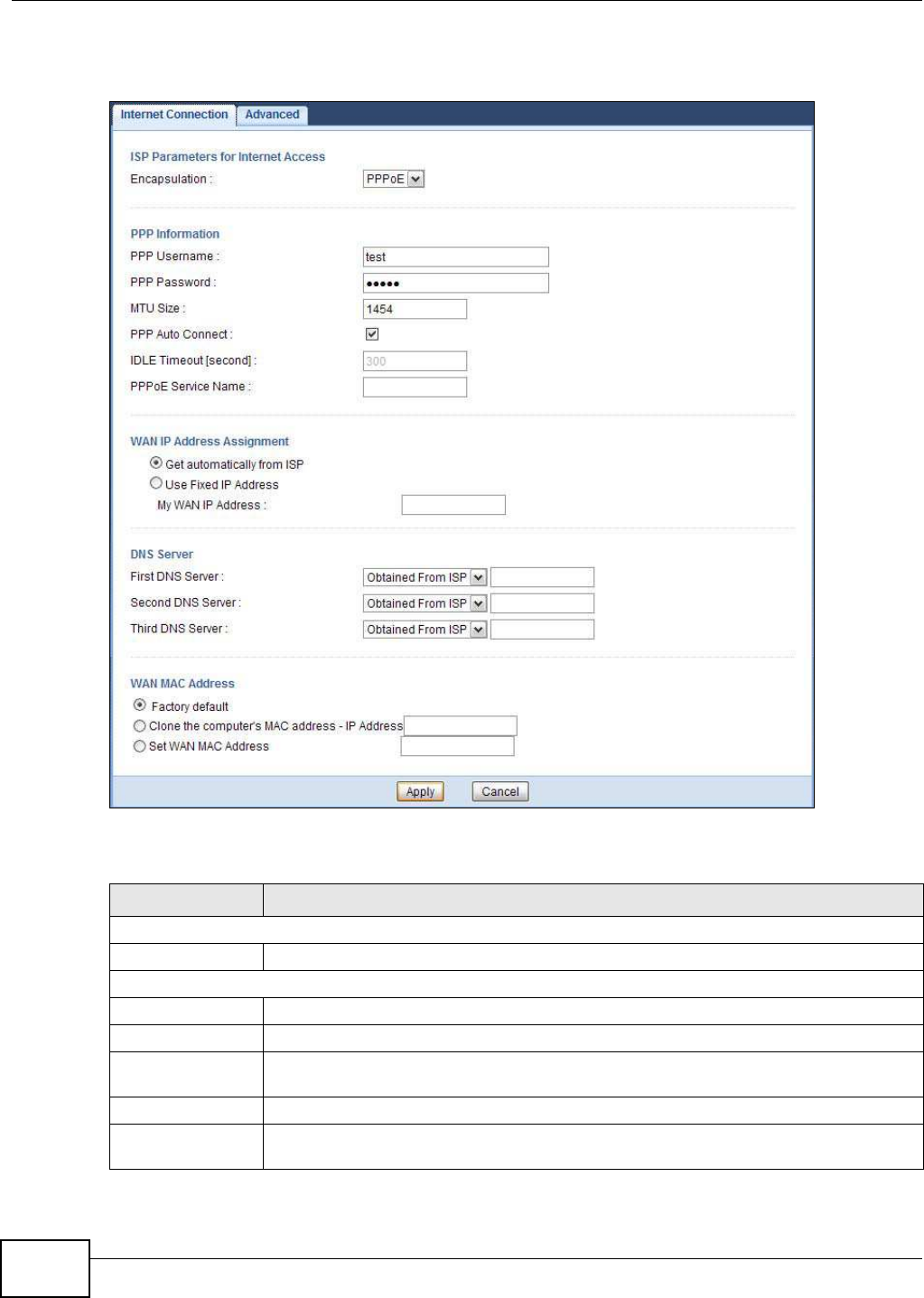
Chapter 11 WAN
NBG5615 User’s Guide
100
This screen displays when you select PPPoE encapsulation.
Figure 54 Network > WAN > Internet Connection: PPPoE Encapsulation
The following table describes the labels in this screen.
Table 33 Network > WAN > Internet Connection: PPPoE Encapsulation
LABEL DESCRIPTION
ISP Parameters for Internet Access
Encapsulation Select PPPoE if you connect to your Internet via dial-up.
PPP Information
PPP Username Type the user name given to you by your ISP.
PPP Password Type the password associated with the user name above.
MTU Size Enter the Maximum Transmission Unit (MTU) or the largest packet size per frame that
your NBG5615 can receive and process.
PPP Auto Connect Select this option if you do not want the connection to time out.
Idle Timeout
(second)
This value specifies the time in minutes that elapses before the router automatically
disconnects from the PPPoE server.

Chapter 11 WAN
NBG5615 User’s Guide 101
11.4.3 PPTP Encapsulation
Point-to-Point Tunneling Protocol (PPTP) is a network protocol that enables secure transfer of data
from a remote client to a private server, creating a Virtual Private Network (VPN) using TCP/IP-
based networks.
PPTP supports on-demand, multi-protocol and virtual private networking over public networks, such
as the Internet.
PPPoE Service
Name
Enter the PPPoE service name specified in the ISP account.
WAN IP Address Assignment
Get automatically
from ISP
Select this option If your ISP did not assign you a fixed IP address. This is the default
selection.
Use Fixed IP
Address
Select this option If the ISP assigned a fixed IP address.
My WAN IP
Address Enter your WAN IP address in this field if you selected Use Fixed I P Address.
DNS Server
First DNS Server
Second DNS
Server
Third DNS Server
Select Obtained From I SP if your ISP dynamically assigns DNS server information (and
the NBG5615's WAN IP address). The field to the right displays the (read-only) DNS
server IP address that the ISP assigns.
Select User-Defined if you have the IP address of a DNS server. Enter the DNS server's
IP address in the field to the right. If you chose User-Defined, but leave the IP address
set to 0.0.0.0, User- Defined changes to None after you click Apply. If you set a second
choice to User-Defined, and enter the same IP address, the second User-Defined
changes to None after you click Apply.
Select None if you do not want to configure DNS servers. If you do not configure a DNS
server, you must know the IP address of a computer in order to access it.
WAN MAC Address The MAC address section allows users to configure the WAN port's MAC address by using
the NBG5615’s MAC address, copying the MAC address from a computer on your LAN or
manually entering a MAC address.
Factory default Select Factory default to use the factory assigned default MAC Address.
Clone the
computer’s MAC
address - IP
Address
Select Clone the com puter's MAC address - I P Address and enter the IP address of
the computer on the LAN whose MAC you are cloning.
Set WAN MAC
Address
Select this option and enter the MAC address you want to use.
Apply Click Apply to save your changes back to the NBG5615.
Cancel Click Cancel to begin configuring this screen afresh.
Table 33 Network > WAN > Internet Connection: PPPoE Encapsulation (continued)
LABEL DESCRIPTION
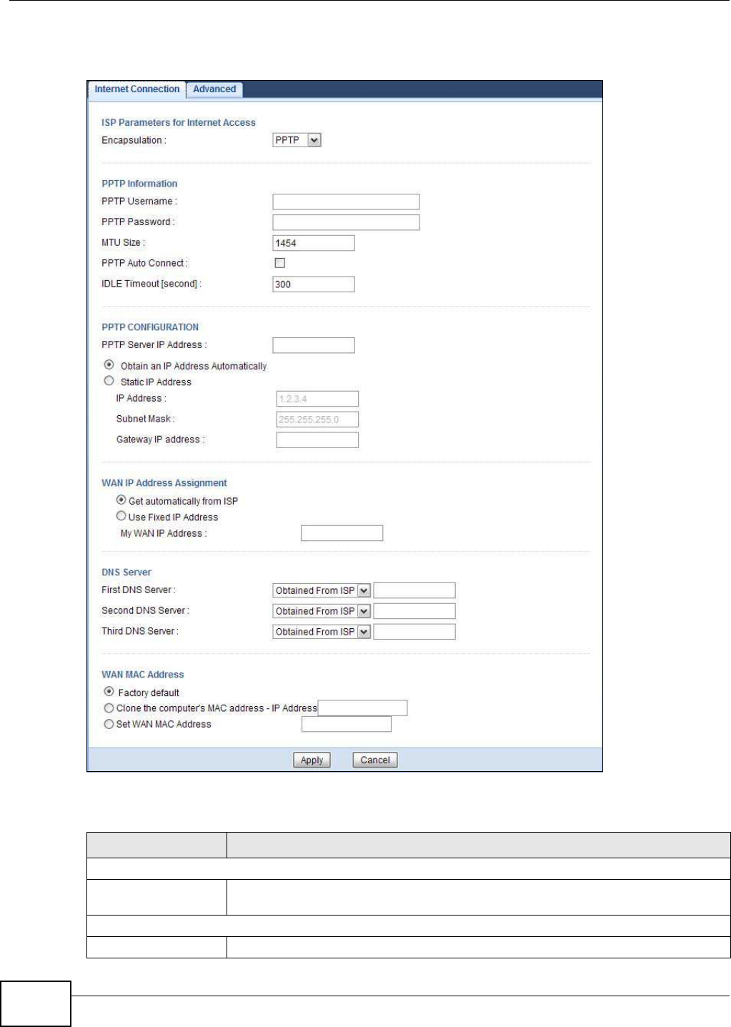
Chapter 11 WAN
NBG5615 User’s Guide
102
This screen displays when you select PPTP encapsulation.
Figure 55 Network > WAN > Internet Connection: PPTP Encapsulation
The following table describes the labels in this screen.
Table 34 Network > WAN > Internet Connection: PPTP Encapsulation
LABEL DESCRIPTION
ISP Parameters for Internet Access
Encapsulation To configure a PPTP client, you must configure the User Nam e and Passw ord fields
for a PPP connection and the PPTP parameters for a PPTP connection.
PPTP Information
PPTP Username Type the user name given to you by your ISP.

Chapter 11 WAN
NBG5615 User’s Guide 103
PPTP Password Type the password associated with the User Name above.
MTU Size Enter the Maximum Transmission Unit (MTU) or the largest packet size per frame that
your NBG5615 can receive and process.
PPPTP Auto Connect Select this option if you do not want the connection to time out.
Idle Timeout This value specifies the time in minutes that elapses before the NBG5615
automatically disconnects from the PPTP server.
PPTP Configuration
PPTP Server IP
Address
Type the IP address of the PPTP server.
Obtain an IP Address
Automatically
Select this option If your ISP did not assign you a fixed IP address. This is the default
selection.
Static IP Address Select this option If the ISP assigned a fixed IP address.
IP Address Enter your WAN IP address in this field if you selected Use Fixed I P Address.
Subnet Mask Your NBG5615 will automatically calculate the subnet mask based on the IP address
that you assign. Unless you are implementing subnetting, use the subnet mask
computed by the NBG5615.
Gateway IP
Address Enter a Gatew ay I P Address (if your ISP gave you one) in this field.
WAN IP Address Assignment
Get automatically
from ISP
Select this to get your WAN IP address from your ISP.
Use Fixed IP Address Select this option If the ISP assigned a fixed IP address.
My WAN IP
Address Enter your WAN IP address in this field if you selected Use Fixed I P Address.
DNS Server
First DNS Server
Second DNS Server
Third DNS Server
Select Obtained From I SP if your ISP dynamically assigns DNS server information
(and the NBG5615's WAN IP address). The field to the right displays the (read-only)
DNS server IP address that the ISP assigns.
Select User- Defined if you have the IP address of a DNS server. Enter the DNS
server's IP address in the field to the right. If you chose User-Defined, but leave the
IP address set to 0.0.0.0, User-Defined changes to None after you click Apply. If
you set a second choice to User-Defined, and enter the same IP address, the second
User-Defined changes to None after you click Apply.
Select None if you do not want to configure DNS servers. If you do not configure a
DNS server, you must know the IP address of a computer in order to access it.
WAN MAC Address The MAC address section allows users to configure the WAN port's MAC address by
either using the NBG5615’s MAC address, copying the MAC address from a computer
on your LAN or manually entering a MAC address.
Factory default Select Factory default to use the factory assigned default MAC Address.
Clone the computer’s
MAC address - IP
Address
Select Clone the com puter's MAC address - I P Address and enter the IP address
of the computer on the LAN whose MAC you are cloning.
Set WAN MAC Address Select this option and enter the MAC address you want to use.
Apply Click Apply to save your changes back to the NBG5615.
Cancel Click Cancel to begin configuring this screen afresh.
Table 34 Network > WAN > Internet Connection: PPTP Encapsulation (continued)
LABEL DESCRIPTION
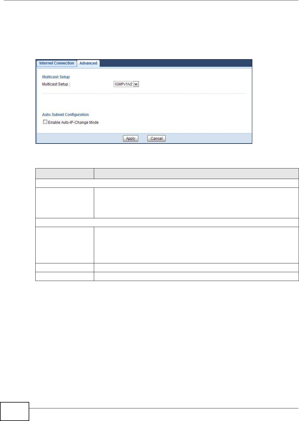
Chapter 11 WAN
NBG5615 User’s Guide
104
11.5 Advanced WAN Screen
To change your NBG5615’s advanced WAN settings, click Netw ork > W AN > Advanced. The
screen appears as shown.
Figure 56 Network > WAN > Advanced
The following table describes the labels in this screen.
Table 35 Network > WAN > Advanced
LABEL DESCRIPTION
Multicast Setup
Multicast Select I GMPv1 / v2 to enable multicasting. This applies to traffic routed from the
WAN to the LAN.
Select None to disable this feature. This may cause incoming traffic to be dropped or
sent to all connected network devices.
Auto-Subnet Configuration
Enable Auto-IP-
Change mode
Select this option to have the NBG5615 change its LAN IP address to 10.0.0.1 or
192.168.1.1 accordingly when the NBG5615 gets a dynamic WAN IP address in the
same subnet as the LAN IP address 192.168.1.1 or 10.0.0.1.
The NAT, DHCP server and firewall functions on the NBG5615 are still available in this
mode.
Apply Click Apply to save your changes back to the NBG5615.
Cancel Click Cancel to begin configuring this screen afresh.
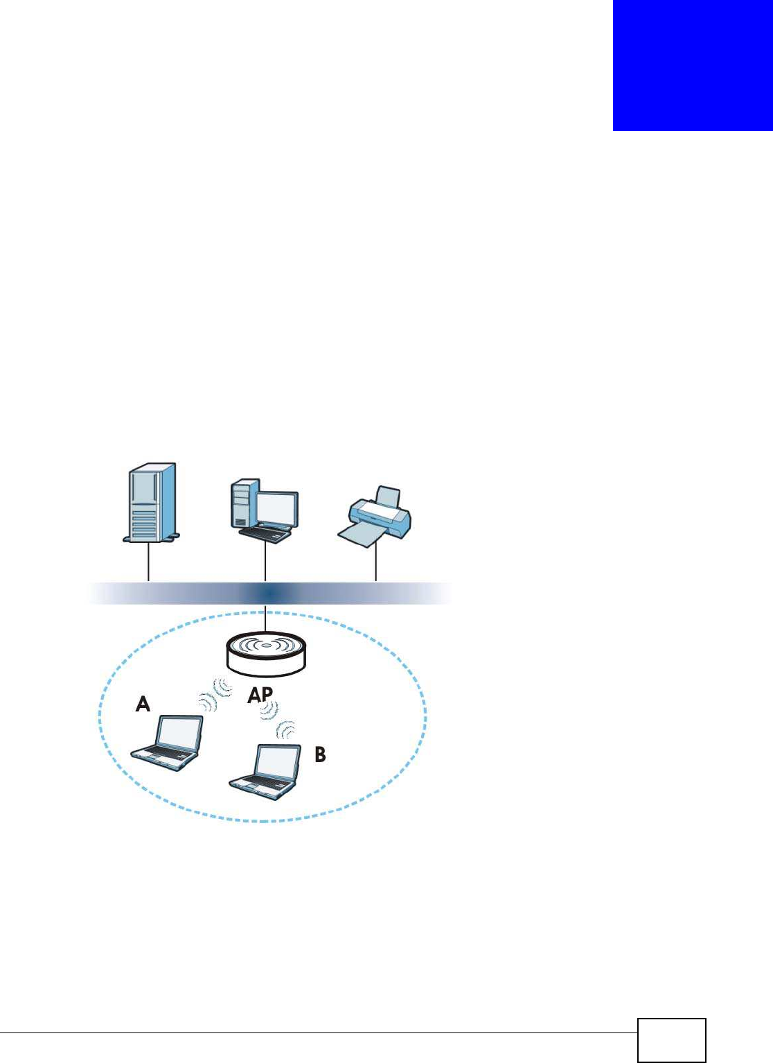
NBG5615 User’s Guide 105
CHAPTER 12
Wireless LAN
12.1 Overview
This chapter discusses how to configure the wireless network settings in your NBG5615. The
NBG5615 is able to function both 2.4GHz and 5GHz network at the same time. You can have
different wireless and wireless security settings for 2.4GHz and 5GHz wireless LANs. Click
Configuration > Netw ork > W ireless LAN 2.4G or W ireless LAN 5G to configure to do so.
See the appendices for more detailed information about wireless networks.
The following figure provides an example of a wireless network.
Figure 57 Example of a Wireless Network
The wireless network is the part in the blue circle. In this wireless network, devices A and B are
called wireless clients. The wireless clients use the access point (AP) to interact with other devices
(such as the printer) or with the Internet. Your NBG5615 is the AP.

Chapter 12 Wireless LAN
NBG5615 User’s Guide
106
12.1.1 What You Can Do
•Use the General screen to turn the wireless connection on or off, set up wireless security
between the NBG5615 and the wireless clients, and make other basic configuration changes
(Section 12.2 on page 110).
•Use the More AP screen to set up multiple wireless networks on your NBG5615 (Section 12.4 on
page 118).
•Use the MAC Filter screen to allow or deny wireless stations based on their MAC addresses from
connecting to the NBG5615 (Section 12.5 on page 121).
•Use the Advanced screen to allow intra-BSS networking and set the RTS/CTS Threshold (Section
12.6 on page 123).
•Use the QoS screen to ensure Quality of Service (QoS) in your wireless network (Section 12.7 on
page 123).
•Use the W PS screen to quickly set up a wireless network with strong security, without having to
configure security settings manually (Section 12.8 on page 124).
•Use the W PS Station screen to add a wireless station using WPS (Section 12.9 on page 126).
•Use the Scheduling screen to set the times your wireless LAN is turned on and off (Section
12.10 on page 126).
12.1.2 What You Should Know
Every wireless network must follow these basic guidelines.
• Every wireless client in the same wireless network must use the same SSID.
The SSID is the name of the wireless network. It stands for Service Set IDentity.
• If two wireless networks overlap, they should use different channels.
Like radio stations or television channels, each wireless network uses a specific channel, or
frequency, to send and receive information.
• Every wireless client in the same wireless network must use security compatible with the AP.
Security stops unauthorized devices from using the wireless network. It can also protect the
information that is sent in the wireless network.
Wireless Security Overview
The following sections introduce different types of wireless security you can set up in the wireless
network.
SSID
Normally, the AP acts like a beacon and regularly broadcasts the SSID in the area. You can hide the
SSID instead, in which case the AP does not broadcast the SSID. In addition, you should change
the default SSID to something that is difficult to guess.
This type of security is fairly weak, however, because there are ways for unauthorized devices to
get the SSID. In addition, unauthorized devices can still see the information that is sent in the
wireless network.

Chapter 12 Wireless LAN
NBG5615 User’s Guide 107
MAC Address Filter
Every wireless client has a unique identification number, called a MAC address.1 A MAC address is
usually written using twelve hexadecimal characters2; for example, 00A0C5000002 or
00:A0:C5:00:00:02. To get the MAC address for each wireless client, see the appropriate User’s
Guide or other documentation.
You can use the MAC address filter to tell the AP which wireless clients are allowed or not allowed to
use the wireless network. If a wireless client is allowed to use the wireless network, it still has to
have the correct settings (SSID, channel, and security). If a wireless client is not allowed to use the
wireless network, it does not matter if it has the correct settings.
This type of security does not protect the information that is sent in the wireless network.
Furthermore, there are ways for unauthorized devices to get the MAC address of an authorized
wireless client. Then, they can use that MAC address to use the wireless network.
User Authentication
You can make every user log in to the wireless network before they can use it. This is called user
authentication. However, every wireless client in the wireless network has to support IEEE 802.1x
to do this.
For wireless networks, there are two typical places to store the user names and passwords for each
user.
• In the AP: this feature is called a local user database or a local database.
• In a RADIUS server: this is a server used in businesses more than in homes.
If your AP does not provide a local user database and if you do not have a RADIUS server, you
cannot set up user names and passwords for your users.
Unauthorized devices can still see the information that is sent in the wireless network, even if they
cannot use the wireless network. Furthermore, there are ways for unauthorized wireless users to
get a valid user name and password. Then, they can use that user name and password to use the
wireless network.
Local user databases also have an additional limitation that is explained in the next section.
Encryption
Wireless networks can use encryption to protect the information that is sent in the wireless
network. Encryption is like a secret code. If you do not know the secret code, you cannot
understand the message.
1. Some wireless devices, such as scanners, can detect wireless networks but cannot use wireless networks. These kinds
of wireless devices might not have MAC addresses.
2. Hexadecimal characters are 0, 1, 2, 3, 4, 5, 6, 7, 8, 9, A, B, C, D, E, and F.

Chapter 12 Wireless LAN
NBG5615 User’s Guide
108
The types of encryption you can choose depend on the type of user authentication. (See page 107
for information about this.)
For example, if the wireless network has a RADIUS server, you can choose W PA or W PA2 . If users
do not log in to the wireless network, you can choose no encryption, Static W EP, W PA- PSK, or
W PA2 -PSK.
Usually, you should set up the strongest encryption that every wireless client in the wireless
network supports. For example, suppose the AP does not have a local user database, and you do
not have a RADIUS server. Therefore, there is no user authentication. Suppose the wireless network
has two wireless clients. Device A only supports WEP, and device B supports WEP and WPA.
Therefore, you should set up Static W EP in the wireless network.
Note: It is recommended that wireless networks use W PA- PSK, W PA, or stronger
encryption. IEEE 802.1x and WEP encryption are better than none at all, but it is
still possible for unauthorized devices to figure out the original information pretty
quickly.
Note: It is not possible to use W PA- PSK, W PA or stronger encryption with a local user
database. In this case, it is better to set up stronger encryption with no
authentication than to set up weaker encryption with the local user database.
When you select W PA2 or W PA2 -PSK in your NBG5615, you can also select an option (W PA/
W PA-PSK Com patible) to support WPA/WPA-PSK as well. In this case, if some wireless clients
support WPA and some support WPA2, you should set up W PA2 -PSK or W PA2 (depending on the
type of wireless network login) and select the W PA/W PA-PSK Com patible option in the
NBG5615.
Many types of encryption use a key to protect the information in the wireless network. The longer
the key, the stronger the encryption. Every wireless client in the wireless network must have the
same key.
Guest WLAN
Guest WLAN allows you to set up a wireless network where users can access to Internet via the
NBG5615 (Z), but not other networks connected to the Z. In the following figure, a guest user can
access the Internet from the guest wireless network A via Z but not the home or company network
N.
Note: The home or company network N and Guest WLAN network are independent
networks.
Note: Only Router mode supports guest WLAN.
Table 36 Types of Encryption for Each Type of Authentication
NO AUTHENTICATION RADIUS SERVER
W eakest No Security WPA
Static WEP
WPA-PSK
Strongest WPA2-PSK WPA2
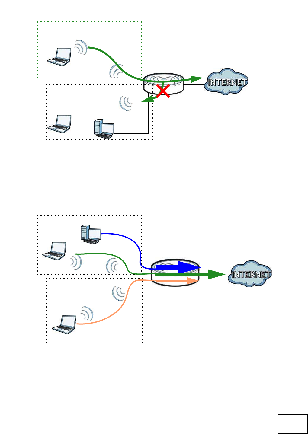
Chapter 12 Wireless LAN
NBG5615 User’s Guide 109
Figure 58 Guest Wireless LAN Network
Guest WLAN Bandwidth
The Guest WLAN Bandwidth function allows you to restrict the maximum bandwidth for the guest
wireless network. Additionally, you can also define bandwidth for your home or office network. An
example is shown next to define maximum bandwidth for your networks (A is Guest WLAN and N is
home or company network.)
Figure 59 Example: Bandwidth for Different Networks
WPS
WiFi Protected Setup (WPS) is an industry standard specification, defined by the WiFi Alliance. WPS
allows you to quickly set up a wireless network with strong security, without having to configure
security settings manually. Depending on the devices in your network, you can either press a
button (on the device itself, or in its configuration utility) or enter a PIN (Personal Identification
N
A
Z
600 kbps
100 kbps
300 kbps
N
A
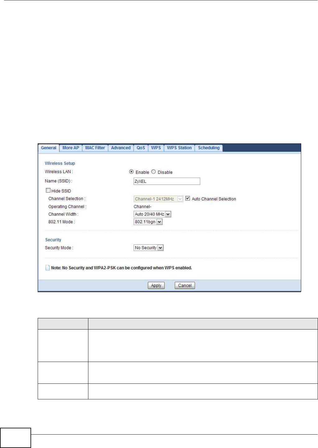
Chapter 12 Wireless LAN
NBG5615 User’s Guide
110
Number) in the devices. Then, they connect and set up a secure network by themselves. See how
to set up a secure wireless network using WPS in the Section 9.2 on page 73.
12.2 General Wireless LAN Screen
Use this screen to configure the SSID and wireless security of the wireless LAN.
Note: If you are configuring the NBG5615 from a computer connected to the wireless LAN
and you change the NBG5615’s SSID, channel or security settings, you will lose
your wireless connection when you press Apply to confirm. You must then change
the wireless settings of your computer to match the NBG5615’s new settings.
Click Netw ork > W ireless LAN 2 .4 G/ 5 G to open the General screen.
Figure 60 Network > Wireless LAN 2.4G/5G > General
The following table describes the general wireless LAN labels in this screen.
Table 37 Network > Wireless LAN 2.4G/5G > General
LABEL DESCRIPTION
Wireless LAN Select Enable to activate the 2.4GHz and/or 5GHz wireless LAN. Select Disable to turn it
off.
You can enable or disable both 2.4GHz and 5GHz wireless LANs by using the W I FI button
located on the back panel of the NBG5615.
Name (SSID) The SSID (Service Set IDentity) identifies the Service Set with which a wireless client is
associated. Enter a descriptive name (up to 32 printable characters found on a typical
English language keyboard) for the wireless LAN.
Hide SSID Select this check box to hide the SSID in the outgoing beacon frame so a station cannot
obtain the SSID through scanning using a site survey tool.

Chapter 12 Wireless LAN
NBG5615 User’s Guide 111
Channel Selection Set the operating frequency/channel depending on your particular region.
Select a channel from the drop-down list box. The options vary depending on the
frequency band and the country you are in.
Refer to the Connection Wizard chapter for more information on channels. This option is
only available if Auto Channel Selection is disabled.
Auto Channel
Selection
Select this check box for the NBG5615 to automatically choose the channel with the least
interference. Deselect this check box if you wish to manually select the channel using the
Channel Selection field.
Operating
Channel
This displays the channel the NBG5615 is currently using.
Channel Width Select the wireless channel width used by NBG5615.
A standard 20MHz channel offers transfer speeds of up to 144Mbps (2.4GHz) or 217Mbps
(5GHZ) whereas a 40MHz channel uses two standard channels and offers speeds of up to
300Mbps (2.4GHz) or 450Mbps (5GHZ).
Because not all devices support 40 MHz channels, select Auto 20 / 4 0MHz to allow the
NBG5615 to adjust the channel bandwidth automatically.
40MHz (channel bonding or dual channel) bonds two adjacent radio channels to increase
throughput. The wireless clients must also support 40 MHz. It is often better to use the 20
MHz setting in a location where the environment hinders the wireless signal.
Select 20 MHz if you want to lessen radio interference with other wireless devices in your
neighborhood or the wireless clients do not support channel bonding.
802.11 Mode If you are in the W ireless LAN 2 .4 G > General screen, you can select from the
following:
•80 2 .1 1b: allows either IEEE 802.11b or IEEE 802.11g compliant WLAN devices to
associate with the NBG5615. In this mode, all wireless devices can only transmit at
the data rates supported by IEEE 802.11b.
•80 2 .1 1g: allows IEEE 802.11g compliant WLAN devices to associate with the Device.
IEEE 802.11b compliant WLAN devices can associate with the NBG5615 only when
they use the short preamble type.
•80 2 .1 1bg: allows either IEEE 802.11b or IEEE 802.11g compliant WLAN devices to
associate with the NBG5615. The NBG5615 adjusts the transmission rate
automatically according to the wireless standard supported by the wireless devices.
•80 2 .1 1n: allows IEEE 802.11n compliant WLAN devices to associate with the
NBG5615. This can increase transmission rates, although IEEE 802.11b or IEEE
802.11g clients will not be able to connect to the NBG5615. I
•80 2 .1 1gn: allows either IEEE 802.11g or IEEE 802.11n compliant WLAN devices to
associate with the NBG5615. The transmission rate of your NBG5615 might be
reduced.
•80 2 .1 1 bgn: allows IEEE802.11b, IEEE802.11g and IEEE802.11n compliant WLAN
devices to associate with the NBG5615. The transmission rate of your NBG5615 might
be reduced.
If you are in the W ireless LAN 5 G > General screen, you can select from the following:
•80 2 .1 1a: allows only IEEE 802.11a compliant WLAN devices to associate with the
NBG5615.
•80 2 .1 1an: allows both IEEE802.11n and IEEE802.11a compliant WLAN devices to
associate with the NBG5615. The transmission rate of your NBG5615 might be
reduced.
Table 37 Network > Wireless LAN 2.4G/5G > General (continued)
LABEL DESCRIPTION
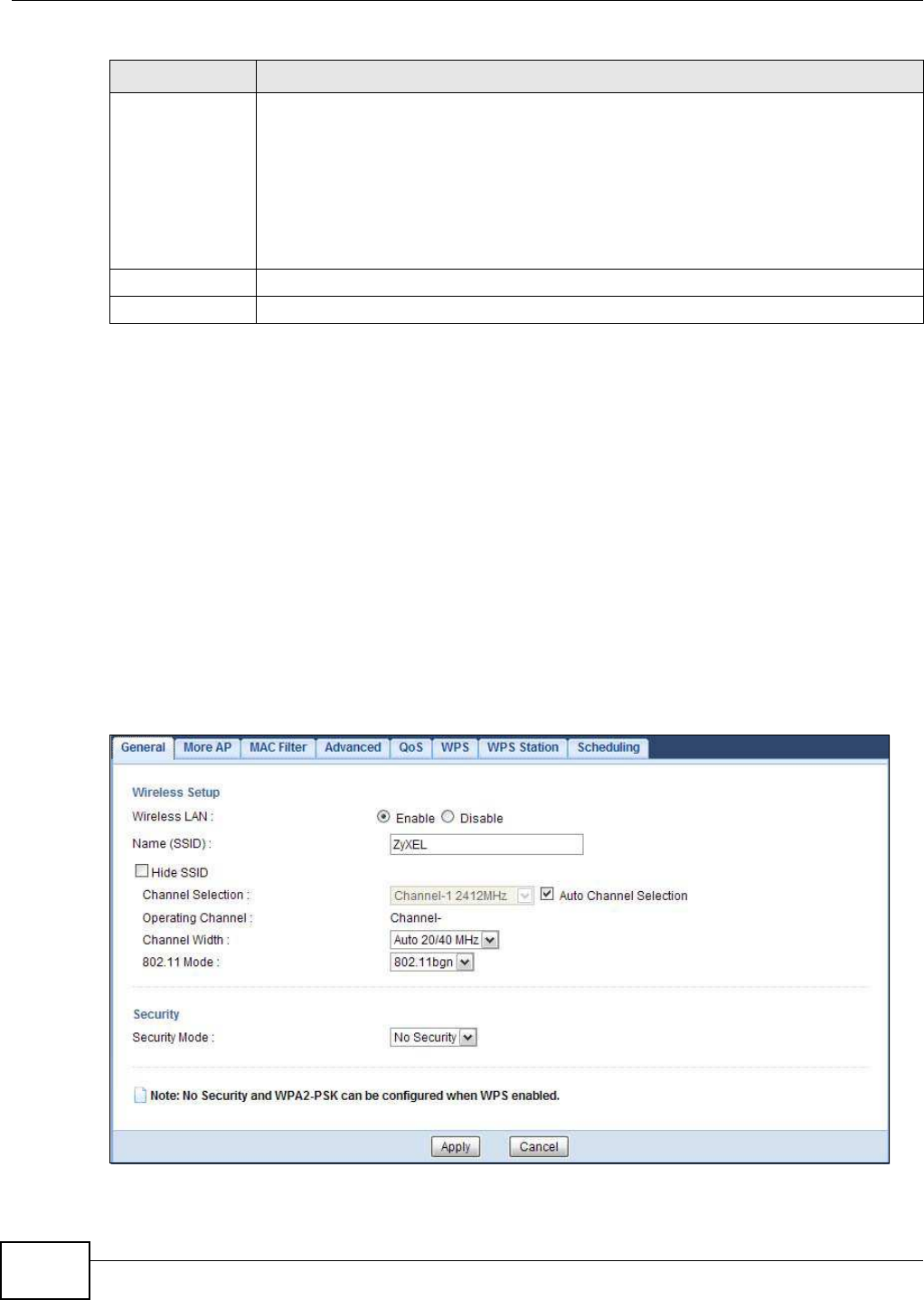
Chapter 12 Wireless LAN
NBG5615 User’s Guide
112
See the rest of this chapter for information on the other labels in this screen.
12.3 Wireless Security
The screen varies depending on what you select in the Security Mode field.
12.3.1 No Security
Select No Security to allow wireless clients to communicate with the access points without any
data encryption.
Note: If you do not enable any wireless security on your NBG5615, your network is
accessible to any wireless networking device that is within range.
Figure 61 Network > Wireless LAN 2.4G/5G > General: No Security
Security Mode Select Static W EP, W PA-PSK, W PA, W PA2 -PSK or W PA2 to add security on this
wireless network. The wireless clients which want to associate to this network must have
same wireless security settings as this device. After you select to use a security,
additional options appears in this screen. See Section 12.3 on page 112 for detailed
information on different security modes. Or you can select No Security to allow any
client to associate this network without authentication.
Note: If the WPS function is enabled (default), only No Security and WPA2-PSK are
available in this field.
Apply Click Apply to save your changes back to the NBG5615.
Cancel Click Cancel to reload the previous configuration for this screen.
Table 37 Network > Wireless LAN 2.4G/5G > General (continued)
LABEL DESCRIPTION

Chapter 12 Wireless LAN
NBG5615 User’s Guide 113
The following table describes the labels in this screen.
12.3.2 WEP Encryption
WEP encryption scrambles the data transmitted between the wireless stations and the access points
to keep network communications private. It encrypts unicast and multicast communications in a
network. Both the wireless stations and the access points must use the same WEP key.
Your NBG5615 allows you to configure up to four 64-bit or 128-bit WEP keys but only one key can
be enabled at any one time.
Select Static W EP from the Security Mode list.
Table 38 Network > Wireless LAN 2.4G/5G > General: No Security
LABEL DESCRIPTION
Security Mode Choose No Security from the drop-down list box.
Apply Click Apply to save your changes back to the NBG5615.
Cancel Click Cancel to reload the previous configuration for this screen.
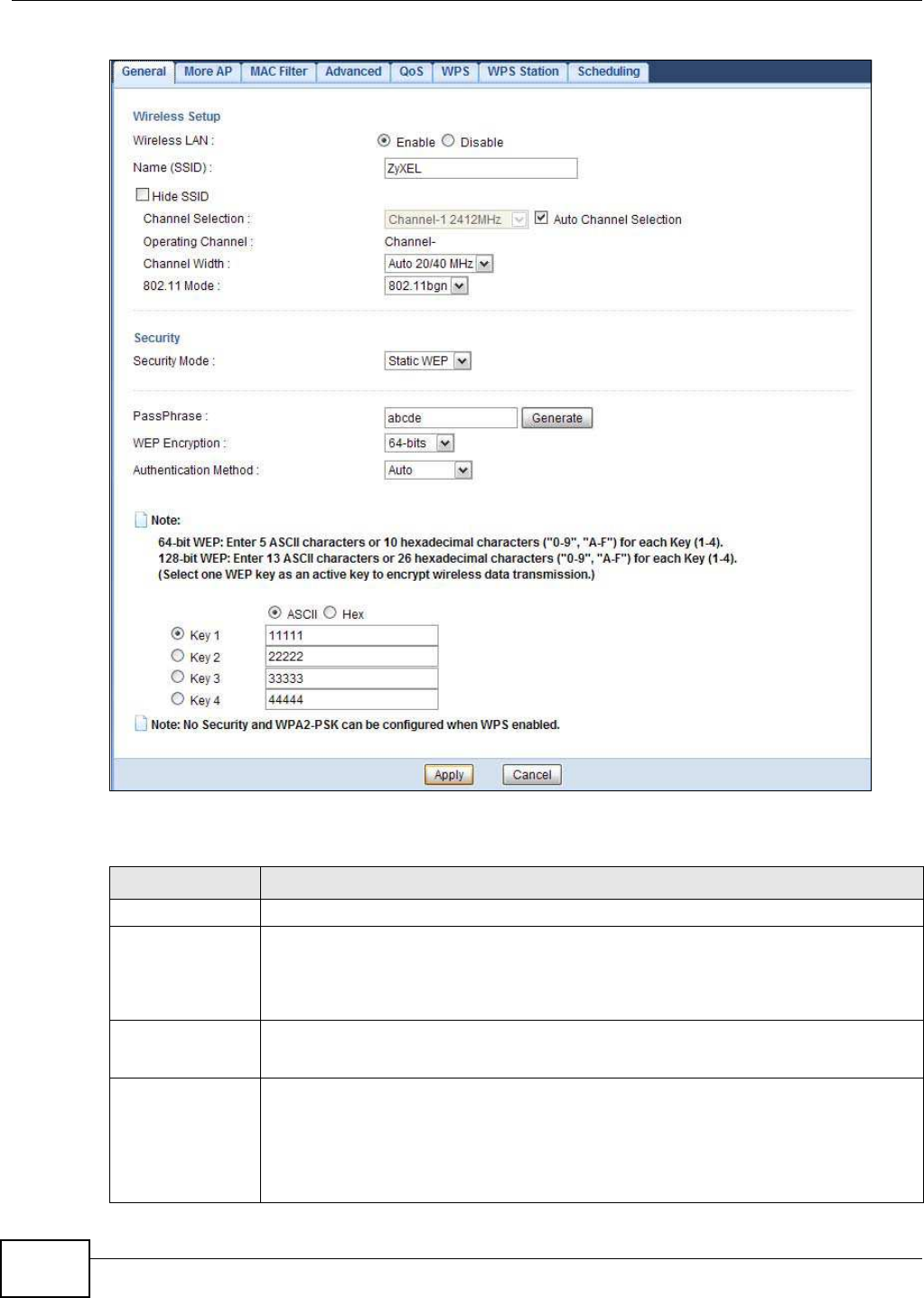
Chapter 12 Wireless LAN
NBG5615 User’s Guide
114
Figure 62 Network > Wireless LAN 2.4G/5G > General: Static WEP
The following table describes the wireless LAN security labels in this screen.
Table 39 Network > Wireless LAN 2.4G/5G > General: Static WEP
LABEL DESCRIPTION
Security Mode Select Static W EP to enable data encryption.
PassPhrase Enter a Passphrase (up to 26 printable characters) and click Generate.
A passphrase functions like a password. In WEP security mode, it is further converted by
the NBG5615 into a complicated string that is referred to as the “key”. This key is
requested from all devices wishing to connect to a wireless network.
WEP Encryption Select 6 4- bits or 1 28 -bits.
This dictates the length of the security key that the network is going to use.
Authentication
Method
Select Auto or Shared Key from the drop-down list box.
This field specifies whether the wireless clients have to provide the WEP key to login to
the wireless client. Keep this setting at Auto unless you want to force a key verification
before communication between the wireless client and the NBG5615 occurs.
Select Shared Key to force the clients to provide the WEP key prior to communication.
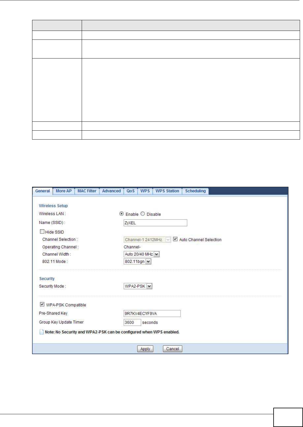
Chapter 12 Wireless LAN
NBG5615 User’s Guide 115
12.3.3 WPA-PSK/WPA2-PSK
Select W PA- PSK or W PA2 -PSK from the Security Mode list.
Figure 63 Network > Wireless LAN 2.4G/5G > General: WPA-PSK/WPA2-PSK
ASCII Select this option in order to enter ASCII characters as WEP key.
Hex Select this option in order to enter hexadecimal characters as a WEP key.
The preceding "0x", that identifies a hexadecimal key, is entered automatically.
Key 1 to Key 4 The WEP keys are used to encrypt data. Both the NBG5615 and the wireless stations
must use the same WEP key for data transmission.
If you chose 6 4- bits, then enter any 5 ASCII characters or 10 hexadecimal characters
("0-9", "A-F").
If you chose 12 8 -bits, then enter 13 ASCII characters or 26 hexadecimal characters ("0-
9", "A-F").
You must configure at least one key, only one key can be activated at any one time. The
default key is key 1.
Apply Click Apply to save your changes back to the NBG5615.
Cancel Click Cancel to reload the previous configuration for this screen.
Table 39 Network > Wireless LAN 2.4G/5G > General: Static WEP (continued)
LABEL DESCRIPTION

Chapter 12 Wireless LAN
NBG5615 User’s Guide
116
The following table describes the labels in this screen.
12.3.4 WPA/WPA2
Select W PA or W PA2 from the Security Mode list.
Note: WPA or WPA2 is not available if you enable WPS before you configure WPA or WPA2
in the W ireless LAN 2 .4 G/ 5 G > General screen.
Table 40 Network > Wireless LAN 2.4G/5G > General: WPA-PSK/WPA2-PSK
LABEL DESCRIPTION
Security Mode Select W PA- PSK or W PA2- PSK to enable data encryption.
WPA-PSK
Compatible
This field appears when you choose W PA2 -PSK as the Security Mode.
Check this field to allow wireless devices using W PA- PSK security mode to connect to
your NBG5615.
Pre-Shared Key W PA-PSK/ W PA2- PSK uses a simple common password for authentication.
Type a pre-shared key from 8 to 63 case-sensitive keyboard characters.
Group Key Update
Timer
The Group Key Update Tim er is the rate at which the AP sends a new group key out to
all clients.
The default is 36 0 0 seconds (60 minutes).
Apply Click Apply to save your changes back to the NBG5615.
Cancel Click Cancel to reload the previous configuration for this screen.
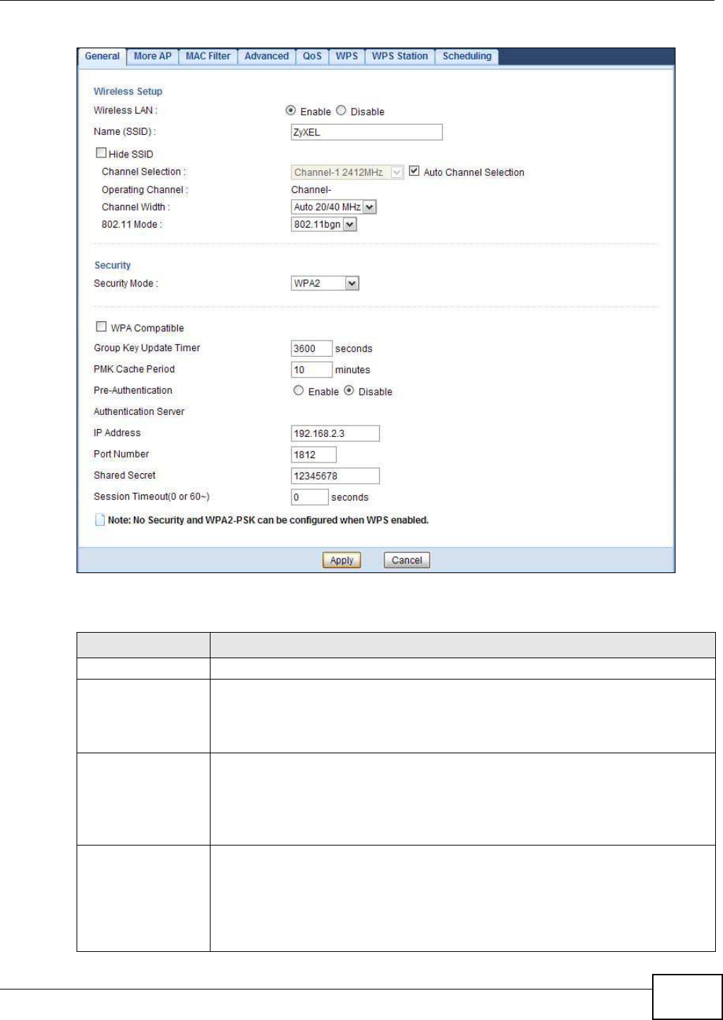
Chapter 12 Wireless LAN
NBG5615 User’s Guide 117
Figure 64 Network > Wireless LAN 2.4G/5G > General: WPA/WPA2
The following table describes the labels in this screen.
Table 41 Network > Wireless LAN 2.4G/5G > General: WPA/WPA2
LABEL DESCRIPTION
Security Mode Select W PA or W PA2 to enable data encryption.
WPA Compatible This check box is available only when you select W PA2 -PSK or W PA2 in the Security
Mode field.
Select the check box to have both WPA2 and WPA wireless clients be able to
communicate with the NBG5615 even when the NBG5615 is using WPA2-PSK or WPA2.
Group Key Update
Timer
The Group Key Update Tim er is the rate at which the AP (if using W PA- PSK/
W PA2 -PSK key management) or RADIUS server (if using W PA/ W PA2 key
management) sends a new group key out to all clients. The re-keying process is the
WPA/WPA2 equivalent of automatically changing the WEP key for an AP and all
stations in a WLAN on a periodic basis. Setting of the Group Key Update Tim er is
also supported in W PA- PSK/ W PA2 -PSK mode.
PMK Cache Period This field is available only when you select W PA2 .
Specify how often wireless clients have to resend usernames and passwords in order
to stay connected. Enter a time interval between 10 and 999999 minutes.
Note: If wireless client authentication is done using a RADIUS server, the
reauthentication timer on the RADIUS server has priority.

Chapter 12 Wireless LAN
NBG5615 User’s Guide
118
12.4 More AP Screen
This screen allows you to enable and configure multiple wireless networks and guest wireless
network settings on the NBG5615.
You can configure up to four SSIDs to enable multiple BSSs (Basic Service Sets) on the NBG5615.
This allows you to use one access point to provide several BSSs simultaneously. You can then
assign varying security types to different SSIDs. Wireless clients can use different SSIDs to
associate with the same access point.
Click Netw ork > W ireless LAN 2 .4 G/ 5G > More AP. The following screen displays.
Pre-Authentication This field is available only when you select W PA2 .
Pre-authentication enables fast roaming by allowing the wireless client (already
connecting to an AP) to perform IEEE 802.1x authentication with another AP before
connecting to it. Select Enable to turn on preauthentication in WAP2. Otherwise,
select Disable.
Authentication Server
IP Address Enter the IP address of the external authentication server in dotted decimal notation.
Port Number Enter the port number of the external authentication server.
You need not change this value unless your network administrator instructs you to do
so with additional information.
Shared Secret Enter a password (up to 127 alphanumeric characters) as the key to be shared
between the external authentication server and the NBG5615.
The key must be the same on the external authentication server and your NBG5615.
The key is not sent over the network.
Session Timeout The NBG5615 automatically disconnects a wireless client from the wireless and wired
networks after a period of inactivity. The wireless client needs to send the username
and password again before it can use the wireless and wired networks again. Some
wireless clients may prompt users for a username and password; other clients may
use saved login credentials. In either case, there is usually a short delay while the
wireless client logs in to the wireless network again.
Enter the time in seconds from 0 to 999999.
Apply Click Apply to save your changes back to the NBG5615.
Cancel Click Cancel to reload the previous configuration for this screen.
Table 41 Network > Wireless LAN 2.4G/5G > General: WPA/WPA2 (continued)
LABEL DESCRIPTION
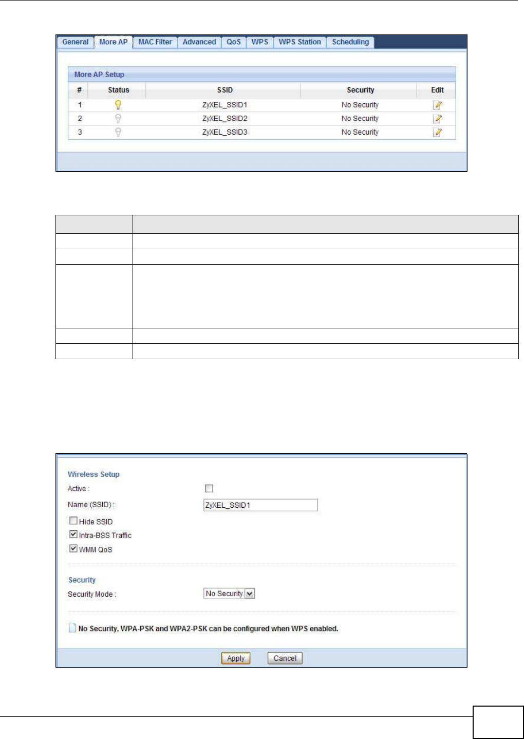
Chapter 12 Wireless LAN
NBG5615 User’s Guide 119
Figure 65 Network > Wireless LAN 2.4G/5G > More AP
The following table describes the labels in this screen.
12.4.1 More AP Edit
Use this screen to edit an SSID profile. Click the Edit icon next to an SSID in the More AP screen.
The following screen displays.
Figure 66 Network > Wireless LAN 2.4G/5G > More AP: Edit
Table 42 Network > Wireless LAN 2.4G/5G > More AP
LABEL DESCRIPTION
#This is the index number of each SSID profile.
Status This shows whether the SSID profile is active (a yellow bulb) or not (a gray bulb).
SSID An SSID profile is the set of parameters relating to one of the NBG5615’s BSSs. The SSID
(Service Set IDentifier) identifies the Service Set with which a wireless device is associated.
This field displays the name of the wireless profile on the network. When a wireless client
scans for an AP to associate with, this is the name that is broadcast and seen in the
wireless client utility.
Security This field indicates the security mode of the SSID profile.
Edit Click the Edit icon to configure the SSID profile.
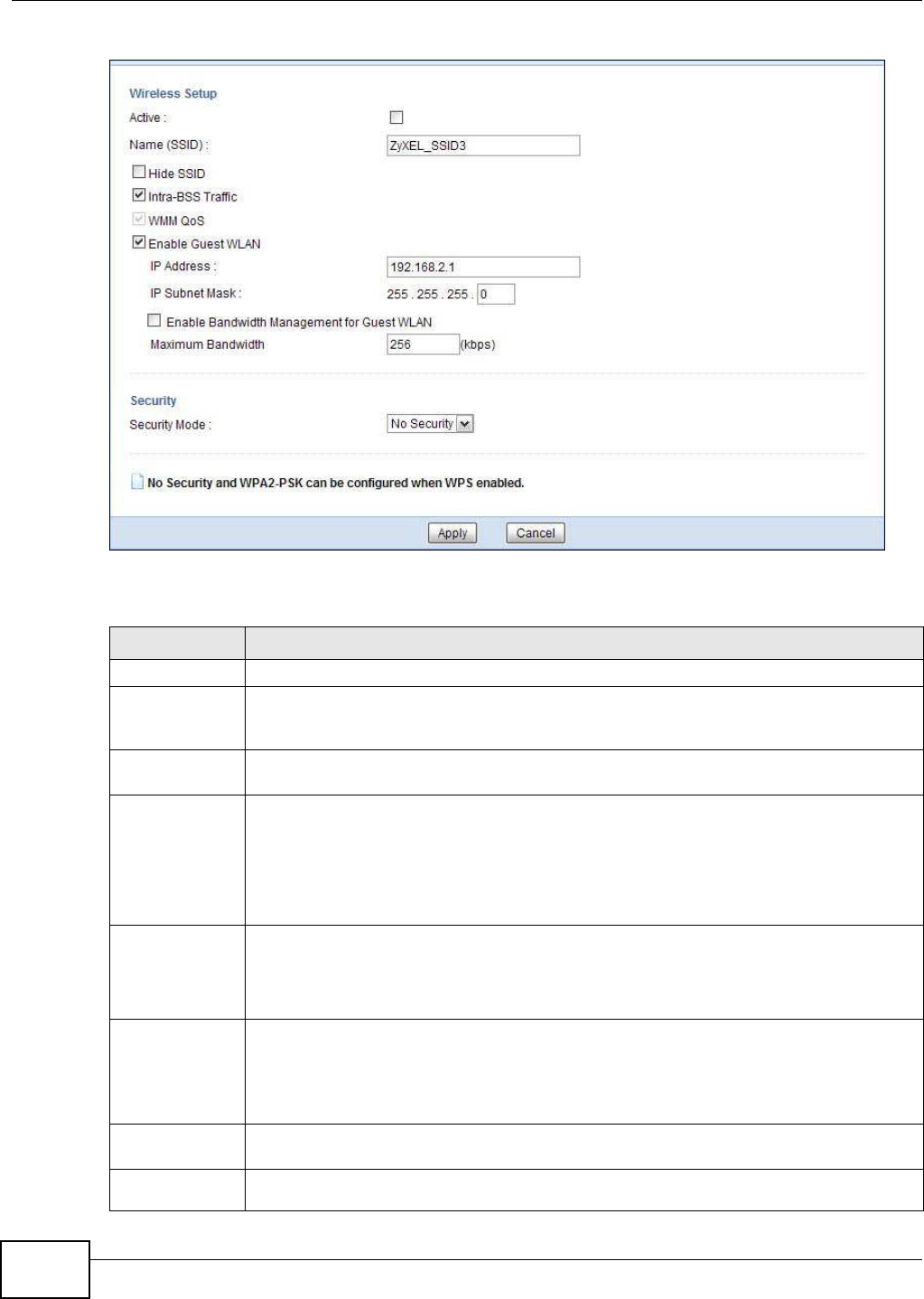
Chapter 12 Wireless LAN
NBG5615 User’s Guide
120
Figure 67 Network > Wireless LAN 2.4G/5G > More AP: Edit (the last SSID)
The following table describes the labels in this screen.
Table 43 Network > Wireless LAN 2.4G/5G > More AP: Edit
LABEL DESCRIPTION
Active Select this to activate the SSID profile.
Name (SSID) The SSID (Service Set IDentity) identifies the Service Set with which a wireless client is
associated. Enter a descriptive name (up to 32 printable characters found on a typical
English language keyboard) for the wireless LAN.
Hide SSID Select this check box to hide the SSID in the outgoing beacon frame so a station cannot
obtain the SSID through scanning using a site survey tool.
Intra-BSS Traffic A Basic Service Set (BSS) exists when all communications between wireless clients or
between a wireless client and a wired network client go through one access point (AP).
Intra-BSS traffic is traffic between wireless clients in the BSS. When Intra-BSS is enabled,
wireless clients can access the wired network and communicate with each other. When
Intra-BSS is disabled, wireless clients can still access the wired network but cannot
communicate with each other.
WMM QoS Check this to have the NBG5615 automatically give a service a priority level according to
the ToS value in the IP header of packets it sends.
WMM QoS (Wifi MultiMedia Quality of Service) gives high priority to voice and video, which
makes them run more smoothly.
Enable Guest
WLAN
Select the check box to activate guest wireless LAN. This is available only for the last SSID
on the NBG5615.
Note: Only Router mode supports guest WLAN. AP mode, Universal Repeater mode, WISP
mode and WISP + Universal Repeater mode don’t support guest WLAN.
IP Address Type an IP address for the devices on the Guest WLAN using this as the gateway IP
address.
IP Subnet
Mask Type the subnet mask for the guest wireless LAN.

Chapter 12 Wireless LAN
NBG5615 User’s Guide 121
12.5 MAC Filter Screen
The MAC filter screen allows you to configure the NBG5615 to give exclusive access to devices
(Allow ) or exclude devices from accessing the NBG5615 (Deny). Every Ethernet device has a
unique MAC (Media Access Control) address. The MAC address is assigned at the factory and
consists of six pairs of hexadecimal characters, for example, 00:A0:C5:00:00:02. You need to know
the MAC address of the devices to configure this screen.
To change your NBG5615’s MAC filter settings, click Netw ork > W ireless LAN 2 .4 G/ 5 G > MAC
Filter. The screen appears as shown.
Enable
Bandwidth
Management
for Guest
WLAN
Select this to turn on bandwidth management for the Guest WLAN network.
Maximum
Bandwidth Enter a number to specify maximum bandwidth the Guest WLAN network can use.
Security Mode Select Static W EP, W PA- PSK, W PA, W PA2 -PSK or W PA2 to add security on this
wireless network. The wireless clients which want to associate to this network must have
same wireless security settings as this device. After you select to use a security, additional
options appears in this screen. See Section 12.3 on page 112 for detailed information on
different security modes. Or you can select No Security to allow any client to associate
this network without authentication.
Note: If the WPS function is enabled (default), only No Security and WPA2-PSK are
available in this field.
Apply Click Apply to save your changes back to the NBG5615.
Cancel Click Cancel to reload the previous configuration for this screen.
Table 43 Network > Wireless LAN 2.4G/5G > More AP: Edit (continued)
LABEL DESCRIPTION
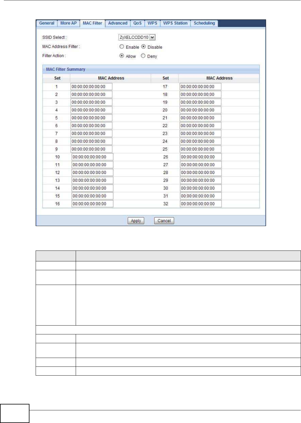
Chapter 12 Wireless LAN
NBG5615 User’s Guide
122
Figure 68 Network > Wireless LAN 2.4G/5G > MAC Filter
The following table describes the labels in this menu.
Table 44 Network > Wireless LAN 2.4G/5G > MAC Filter
LABEL DESCRIPTION
SSID Select Select the SSID for which you want to configure MAC filtering.
MAC Address
Filter
Select to turn on (Enable) or off (Disable) MAC address filtering.
Filter Action Define the filter action for the list of MAC addresses in the MAC Filter Summary table.
Select Allow to permit access to the NBG5615, MAC addresses not listed will be denied
access to the NBG5615.
Select Deny to block access to the NBG5615, MAC addresses not listed will be allowed to
access the NBG5615.
MAC Filter Summary
Set This is the index number of the MAC address.
MAC Address Enter the MAC address of the wireless station that are allowed or denied access to the
NBG5615.
Apply Click Apply to save your changes back to the NBG5615.
Cancel Click Cancel to reload the previous configuration for this screen.
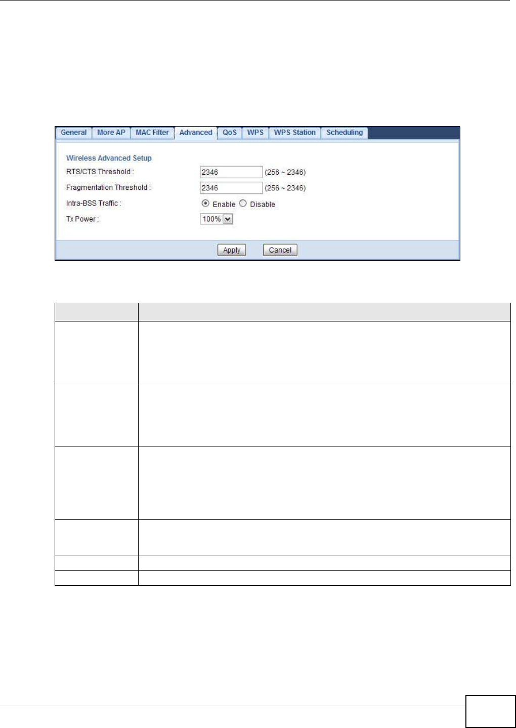
Chapter 12 Wireless LAN
NBG5615 User’s Guide 123
12.6 Wireless LAN Advanced Screen
Use this screen to allow wireless advanced features, such as the output power, RTS/CTS Threshold
settings.
Click Netw ork > W ireless LAN 2 .4 G/ 5 G > Advanced. The screen appears as shown.
Figure 69 Network > Wireless LAN 2.4G/5G > Advanced
The following table describes the labels in this screen.
12.7 Quality of Service (QoS) Screen
The QoS screen allows you to automatically give a service (such as VoIP and video) a priority level.
Table 45 Network > Wireless LAN 2.4G/5G > Advanced
LABEL DESCRIPTION
RTS/CTS
Threshold
Data with its frame size larger than this value will perform the RTS (Request To Send)/
CTS (Clear To Send) handshake.
This field is not configurable and the NBG5615 automatically changes to use the
maximum value if you select 80 2 .1 1n, 802 .1 1 an, 802 .1 1 gn or 80 2 .1 1bgn in the
W ireless LAN 2.4G/ 5G > General screen.
Fragmentation
Threshold
The threshold (number of bytes) for the fragmentation boundary for directed messages.
It is the maximum data fragment size that can be sent.
This field is not configurable and the NBG5615 automatically changes to use the
maximum value if you select 80 2 .1 1n, 802 .1 1 an, 802 .1 1 gn or 80 2 .1 1bgn in the
W ireless LAN 2.4G/ 5G > General screen.
Intra-BSS Traffic A Basic Service Set (BSS) exists when all communications between wireless clients or
between a wireless client and a wired network client go through one access point (AP).
Intra-BSS traffic is traffic between wireless clients in the BSS. When Intra-BSS is
enabled, wireless clients can access the wired network and communicate with each other.
When Intra-BSS is disabled, wireless clients can still access the wired network but cannot
communicate with each other.
Tx Power Set the output power of the NBG5615 in this field. If there is a high density of APs in an
area, decrease the output power of the NBG5615 to reduce interference with other APs.
Select one of the following 100 % , 90% , 75 % , 5 0% , 2 5% or 10 % .
Apply Click Apply to save your changes back to the NBG5615.
Cancel Click Cancel to reload the previous configuration for this screen.
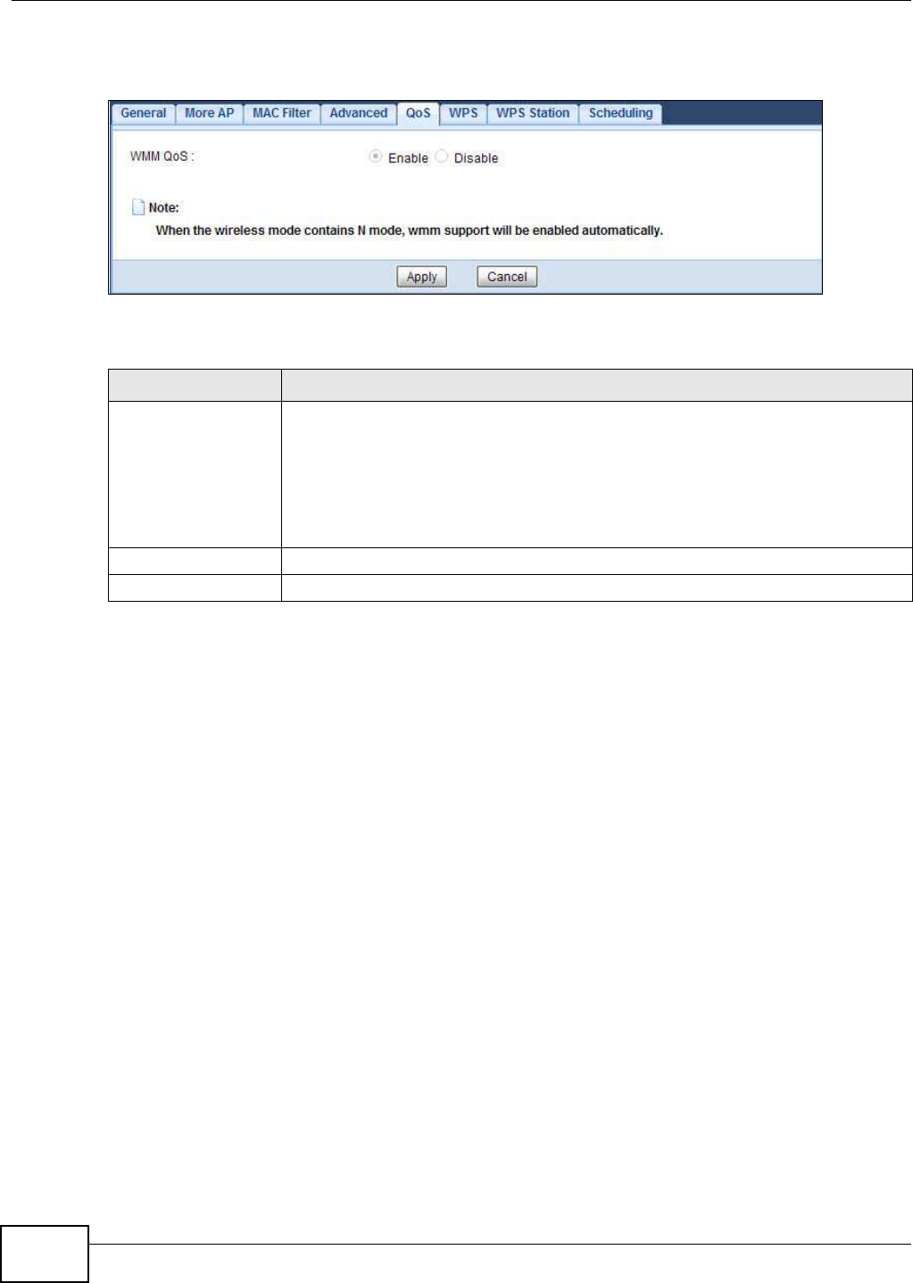
Chapter 12 Wireless LAN
NBG5615 User’s Guide
124
Click Netw ork > W ireless LAN 2 .4 G/ 5 G > QoS. The following screen appears.
Figure 70 Network > Wireless LAN 2.4G/5G > QoS
The following table describes the labels in this screen.
12.8 WPS Screen
Use this screen to enable/disable WPS, view or generate a new PIN number and check current WPS
status. To open this screen, click Netw ork > W ireless LAN 2.4G/ 5G > W PS.
Note: With WPS, wireless clients can only connect to the wireless network using the first
SSID on the NBG5615.
Table 46 Network > Wireless LAN 2.4G/5G > QoS
LABEL DESCRIPTION
WMM QoS Select Enable to have the NBG5615 automatically give a service a priority level
according to the ToS value in the IP header of packets it sends. WMM QoS (Wifi
MultiMedia Quality of Service) gives high priority to voice and video, which makes
them run more smoothly.
This field is not configurable and the NBG5615 automatically enables WMM QoS if you
select 802 .1 1n, 8 0 2 .1 1 a n, 8 02 .11 gn or 8 02.1 1bgn in the W ireless LAN 24 G/ 5G
> General screen.
Apply Click Apply to save your changes to the NBG5615.
Cancel Click Cancel to reload the previous configuration for this screen.
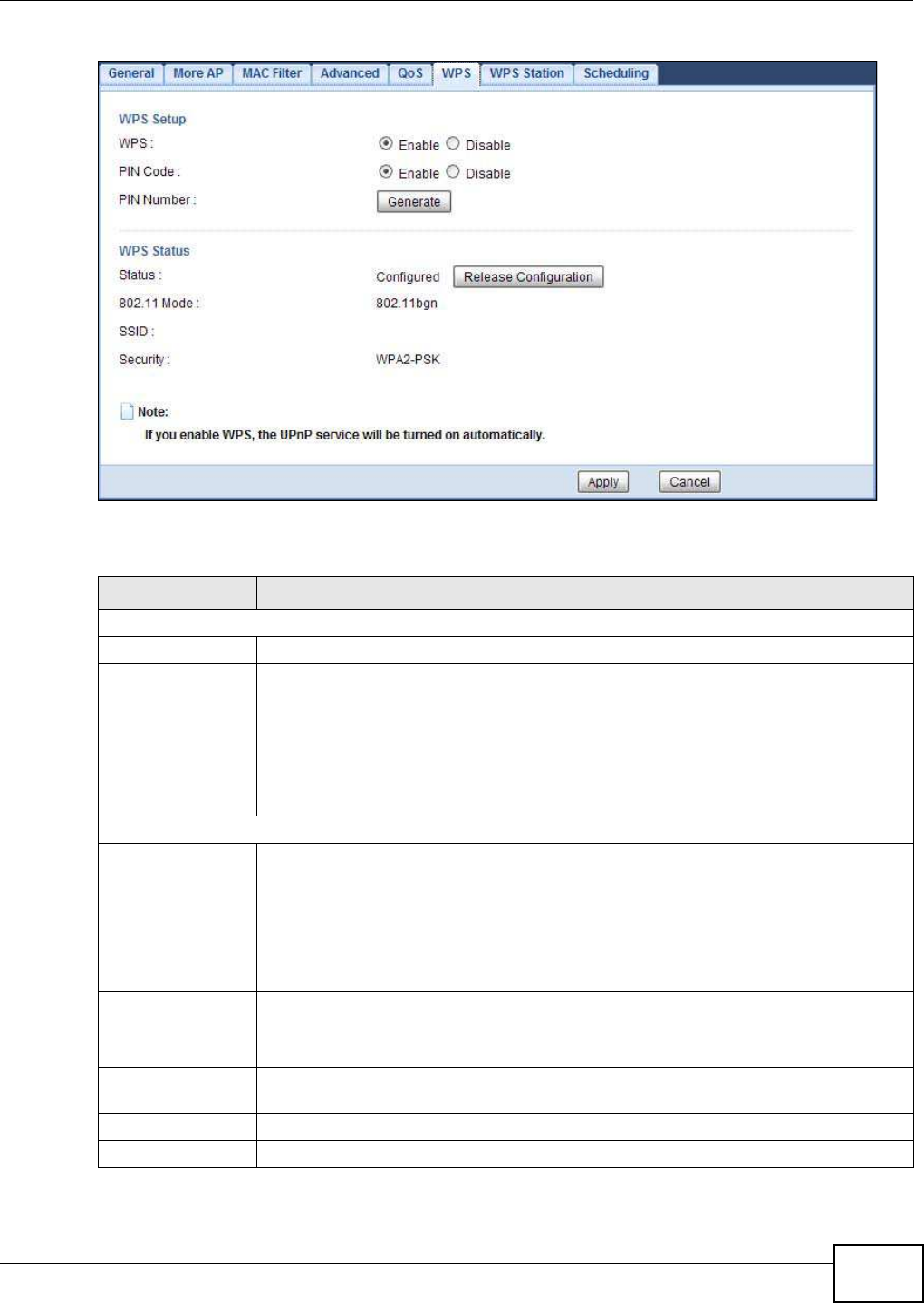
Chapter 12 Wireless LAN
NBG5615 User’s Guide 125
Figure 71 Network > Wireless LAN 2.4G/5G > WPS
The following table describes the labels in this screen.
Table 47 Network > Wireless LAN 2.4G/5G > WPS
LABEL DESCRIPTION
WPS Setup
WPS Select Enable to turn on the WPS feature. Otherwise, select Disable.
PIN Code Select Enable and click Apply to allow the PIN Configuration method. If you select
Disable, you cannot create a new PIN number.
PIN Number This is the WPS PIN (Personal Identification Number) of the NBG5615. Enter this PIN in
the configuration utility of the device you want to connect to the NBG5615 using WPS.
The PIN is not necessary when you use WPS push-button method.
Click Generate to generate a new PIN number.
WPS Status
Status This displays Configured when the NBG5615 has connected to a wireless network using
WPS or when W PS Enable is selected and wireless or wireless security settings have
been changed. The current wireless and wireless security settings also appear in the
screen.
This displays Unconfigured if WPS is disabled and there are no wireless or wireless
security changes on the NBG5615 or you click Release Configuration to remove the
configured wireless and wireless security settings.
Release
Configuration
This button is only available when the WPS status displays Configured.
Click this button to remove all configured wireless and wireless security settings for WPS
connections on the NBG5615.
802.11 Mode This is the 802.11 mode used. Only compliant WLAN devices can associate with the
NBG5615.
SSID This is the name of the wireless network (the NBG5615’s first SSID).
Security This is the type of wireless security employed by the network.
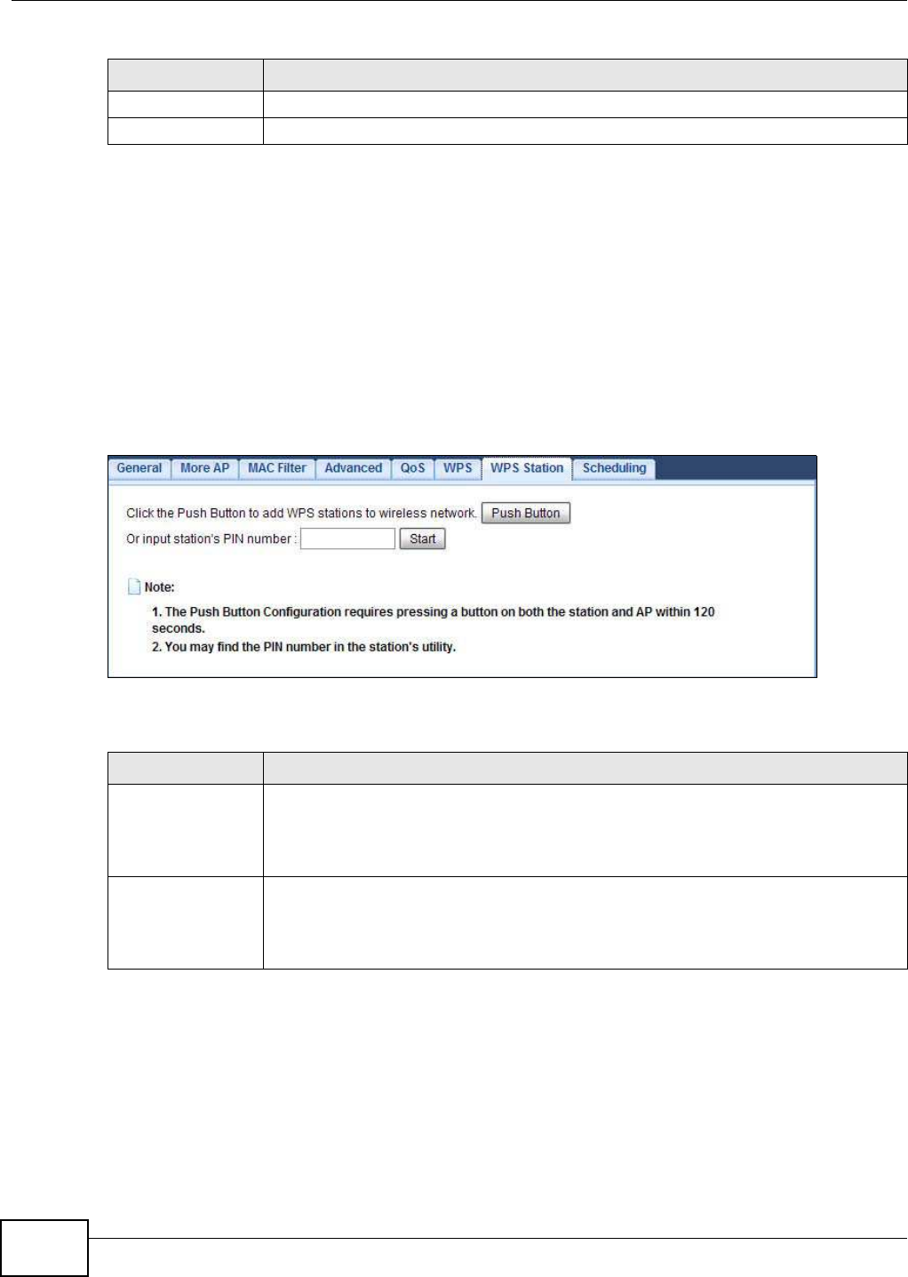
Chapter 12 Wireless LAN
NBG5615 User’s Guide
126
12.9 WPS Station Screen
Use this screen when you want to add a wireless station using WPS. To open this screen, click
Netw ork > W ireless LAN 2.4G/ 5 G > W PS Station tab.
Note: After you click Push Button on this screen, you have to press a similar button in
the wireless station utility within 2 minutes. To add the second wireless station, you
have to press these buttons on both device and the wireless station again after the
first 2 minutes.
Figure 72 Network > Wireless LAN 2.4G/5G > WPS Station
The following table describes the labels in this screen.
12.10 Scheduling Screen
Use this screen to set the times your wireless LAN is turned on and off. Wireless LAN scheduling is
disabled by default. The wireless LAN can be scheduled to turn on or off on certain days and at
certain times. To open this screen, click Netw ork > W ireless LAN 2.4G/ 5G > Scheduling tab.
Apply Click Apply to save your changes back to the NBG5615.
Cancel Click Cancel to reload the previous configuration for this screen.
Table 47 Network > Wireless LAN 2.4G/5G > WPS (continued)
LABEL DESCRIPTION
Table 48 Network > Wireless LAN 2.4G/5G > WPS Station
LABEL DESCRIPTION
Push Button Use this button when you use the PBC (Push Button Configuration) method to configure
wireless stations’s wireless settings.
Click this to start WPS-aware wireless station scanning and the wireless security
information synchronization.
Or input station’s
PIN number
Use this button when you use the PIN Configuration method to configure wireless
station’s wireless settings.
Type the same PIN number generated in the wireless station’s utility. Then click Start to
associate to each other and perform the wireless security information synchronization.
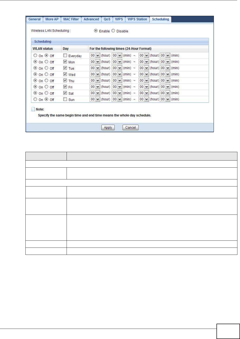
Chapter 12 Wireless LAN
NBG5615 User’s Guide 127
Figure 73 Network > Wireless LAN 2.4G/5G > Scheduling
The following table describes the labels in this screen.
Table 49 Network > Wireless LAN 2.4G/5G > Scheduling
LABEL DESCRIPTION
Wireless LAN Scheduling
Wireless LAN
Scheduling
Select Enable to activate the wireless LAN scheduling feature. Select Disable to turn it
off.
Scheduling
WLAN Status Select On or Off to specify whether the Wireless LAN is turned on or off. This field works
in conjunction with the Day and For the follow ing tim es fields.
Day Select Everyday or the specific days to turn the Wireless LAN on or off. If you select
Everyday you can not select any specific days. This field works in conjunction with the
For the follow ing tim es field.
For the following
times (24-Hour
Format)
Select a begin time using the first set of hour and minute (m in) drop down boxes and
select an end time using the second set of hour and minute (m in) drop down boxes. If
you have chosen On earlier for the WLAN Status the Wireless LAN will turn on between
the two times you enter in these fields. If you have chosen Off earlier for the WLAN
Status the Wireless LAN will turn off between the two times you enter in these fields.
Apply Click Apply to save your changes back to the NBG5615.
Cancel Click Cancel to reload the previous configuration for this screen.

Chapter 12 Wireless LAN
NBG5615 User’s Guide
128
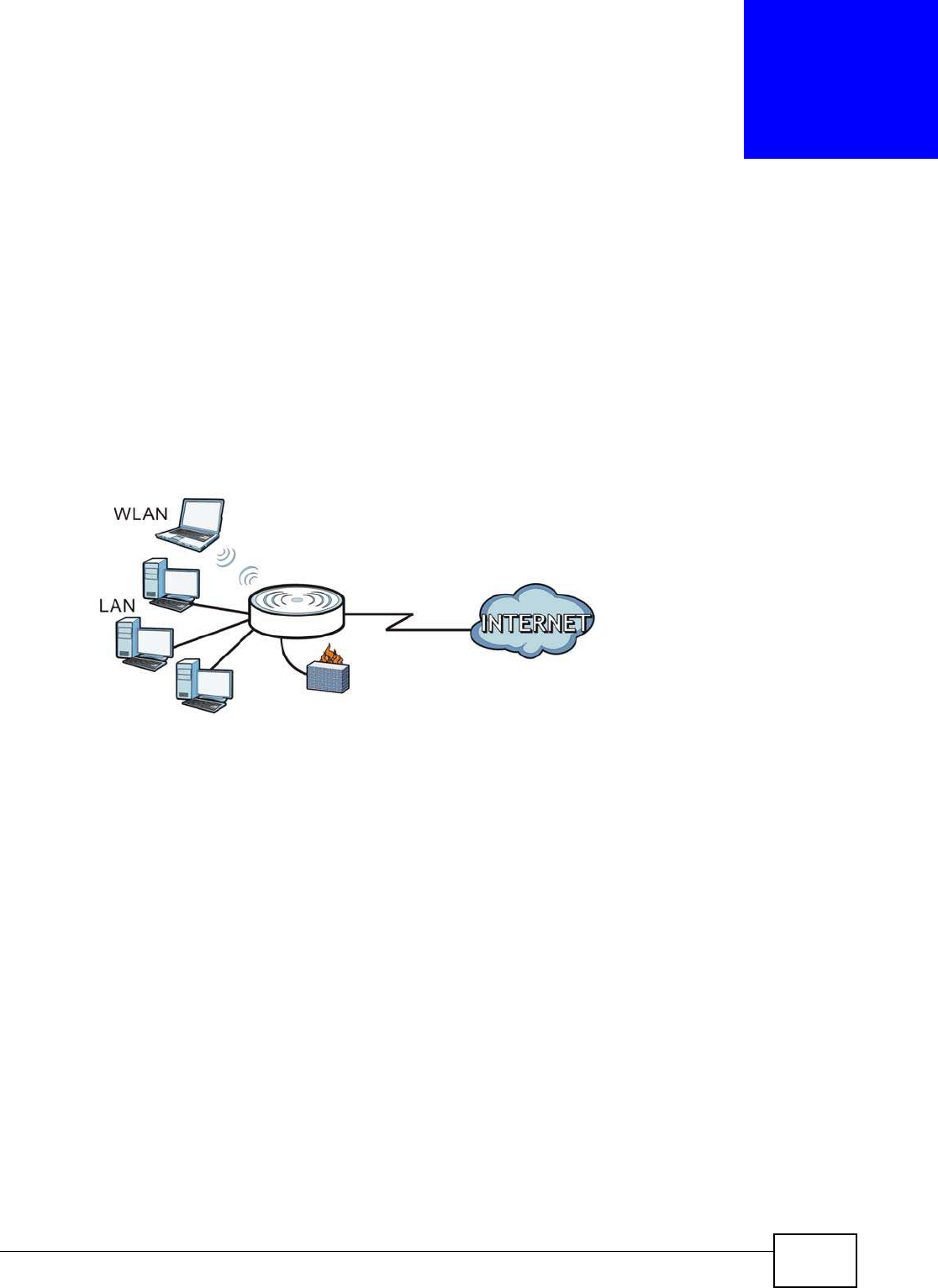
NBG5615 User’s Guide 129
CHAPTER 13
LAN
13.1 Overview
This chapter describes how to configure LAN settings.
A Local Area Network (LAN) is a shared communication system to which many computers are
attached. A LAN is a computer network limited to the immediate area, usually the same building or
floor of a building.
Figure 74 LAN Example
The LAN screens can help you configure a manage IP address, and partition your physical
network into logical networks.
13.2 What You Can Do
•Use the I P screen to change the IP address for your NBG5615 (Section 13.4 on page 130).
•Use the I P Alias screen to have the NBG5615 apply IP alias to create LAN subnets (Section 13.5
on page 131).
13.3 What You Need To Know
The actual physical connection determines whether the NBG5615 ports are LAN or WAN ports.
There are two separate IP networks, one inside the LAN network and the other outside the WAN
network as shown next.
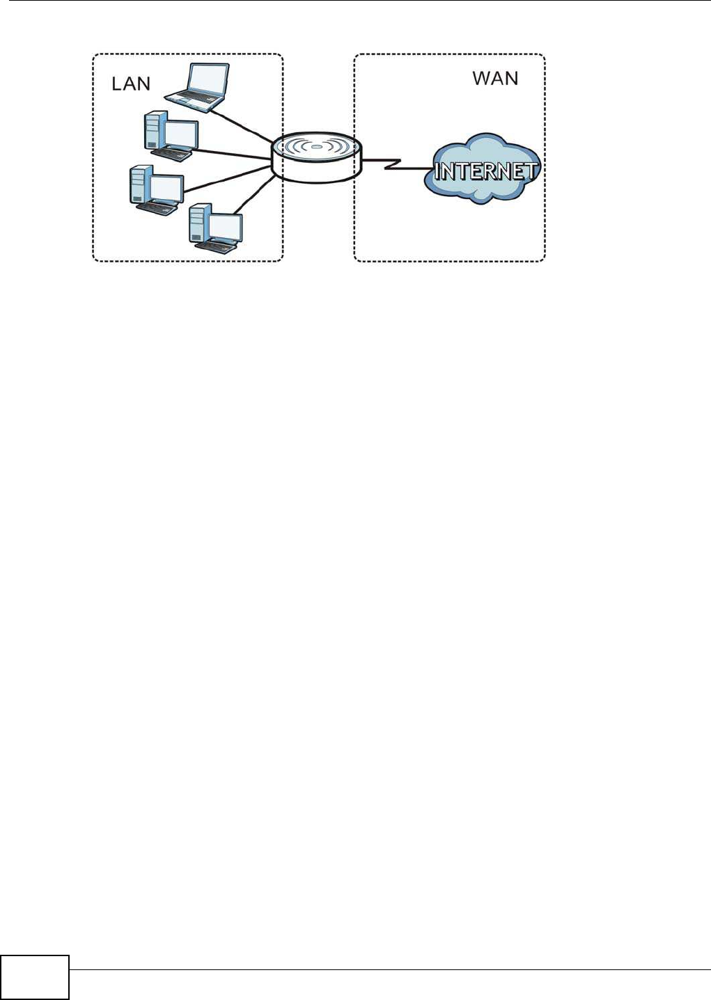
Chapter 13 LAN
NBG5615 User’s Guide
130
Figure 75 LAN and WAN IP Addresses
The LAN parameters of the NBG5615 are preset in the factory with the following values:
• IP address of 192.168.1.1 with subnet mask of 255.255.255.0 (24 bits)
• DHCP server enabled with 32 client IP addresses starting from 192.168.1.33.
These parameters should work for the majority of installations. If your ISP gives you explicit DNS
server address(es), read the embedded Web Configurator help regarding what fields need to be
configured.
13.3.1 IP Pool Setup
The NBG5615 is pre-configured with a pool of 32 IP addresses starting from 192.168.1.33 to
192.168.1.64. This configuration leaves 31 IP addresses (excluding the NBG5615 itself) in the
lower range (192.168.1.2 to 192.168.1.32) for other server computers, for instance, servers for
mail, FTP, TFTP, web, etc., that you may have.
13.3.2 LAN TCP/IP
The NBG5615 has built-in DHCP server capability that assigns IP addresses and DNS servers to
systems that support DHCP client capability.
13.3.3 IP Alias
IP alias allows you to partition a physical network into different logical networks over the same
Ethernet interface. The NBG5615 supports three logical LAN interfaces via its single physical
Ethernet interface with the NBG5615 itself as the gateway for each LAN network.
13.4 LAN IP Screen
Use this screen to change the IP address for your NBG5615. Click Netw ork > LAN > I P.
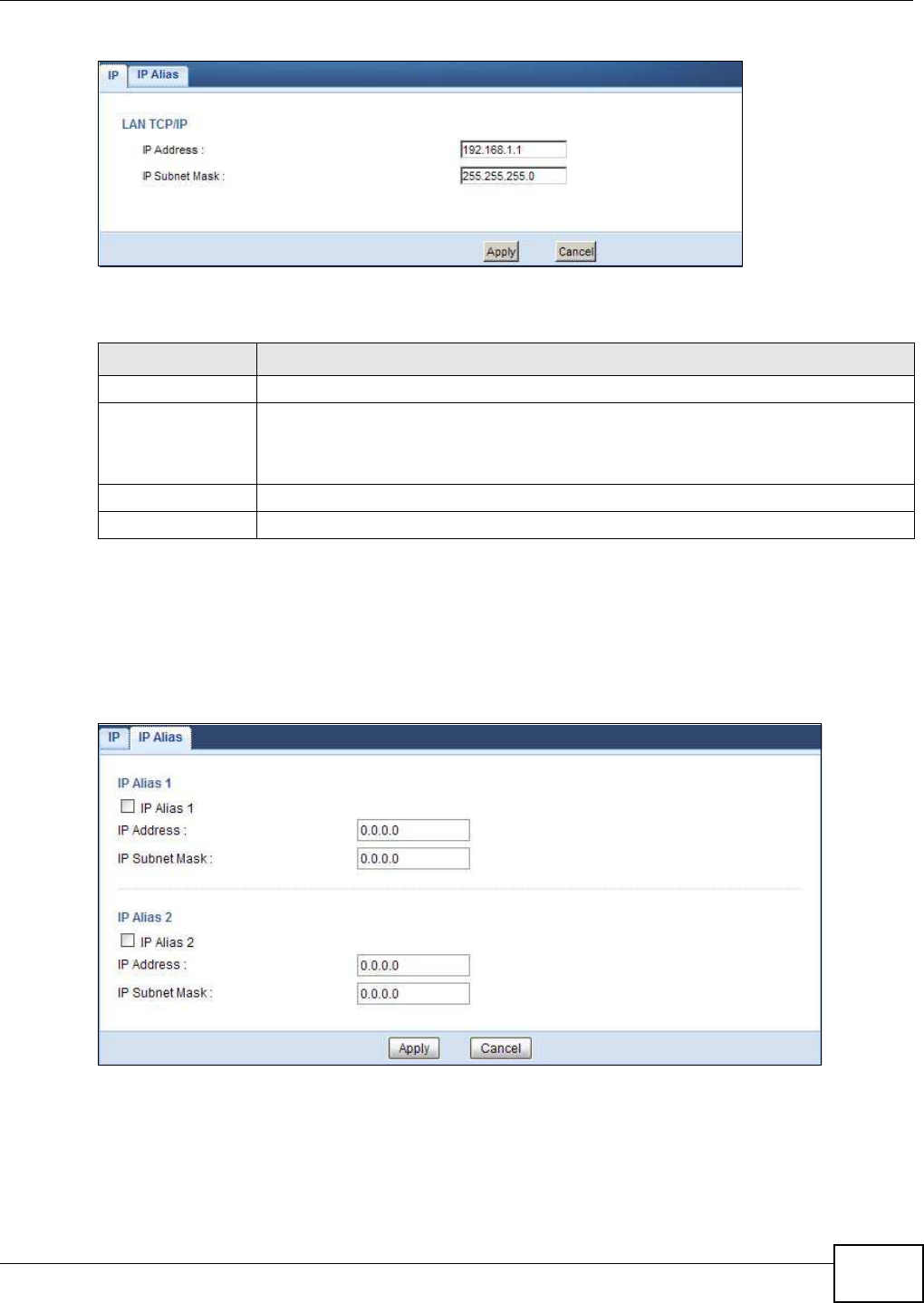
Chapter 13 LAN
NBG5615 User’s Guide 131
Figure 76 Network > LAN > IP
The following table describes the labels in this screen.
13.5 IP Alias Screen
Use this screen to have the NBG5615 apply IP alias to create LAN subnets. Click LAN I P Alias.
Figure 77 Network > LAN > IP Alias
Table 50 Network > LAN > IP
LABEL DESCRIPTION
IP Address Type the IP address of your NBG5615 in dotted decimal notation.
IP Subnet Mask The subnet mask specifies the network number portion of an IP address. Your NBG5615
will automatically calculate the subnet mask based on the IP address that you assign.
Unless you are implementing subnetting, use the subnet mask computed by the
NBG5615.
Apply Click Apply to save your changes back to the NBG5615.
Cancel Click Cancel to begin configuring this screen afresh.

Chapter 13 LAN
NBG5615 User’s Guide
132
The following table describes the labels in this screen.
Table 51 Network > LAN > IP Alias
LABEL DESCRIPTION
IP Alias 1, 2 Check this to enable IP alias to configure another LAN network for the NBG5615.
IP Address Type the IP alias address of your NBG5615 in dotted decimal notation.
IP Subnet Mask The subnet mask specifies the network number portion of an IP address. Your NBG5615
will automatically calculate the subnet mask based on the IP address that you assign.
Unless you are implementing subnetting, use the subnet mask computed by the
NBG5615.
Apply Click Apply to save your changes back to the NBG5615.
Cancel Click Cancel to begin configuring this screen afresh.