ZyXEL Communications NVG2053 Wireless N Gigabit VoIP Gateway User Manual ZyBook2
ZyXEL Communications Corporation Wireless N Gigabit VoIP Gateway ZyBook2
Contents
- 1. User's manual-1
- 2. User's manual-2
User's manual-1
www.zyxel.com
www.zyxel.com
NVG2053
Wireless N Gigabit VoIP Gateway
Copyright © 2011
ZyXEL Communications Corporation
Firmware Version 1.0
Edition 1, 02/2011
Default Login Details
IP Address http://192.168.1.1
Password 1234
About This User's Guide
NVG2053 User’s Guide 3
About This User's Guide
Intended Audience
This manual is intended for people who want to configure the NVG2053 using the
Web Configurator.
Related Documentation
•Quick Start Guide
The Quick Start Guide is designed to help you get up and running right away. It
contains information on setting up your network and configuring for Internet
access.
• Support Disc
Refer to the included CD for support documents.
Documentation Feedback
Send your comments, questions or suggestions to: techwriters@zyxel.com.tw
Thank you!
The Technical Writing Team, ZyXEL Communications Corp.,
6 Innovation Road II, Science-Based Industrial Park, Hsinchu, 30099, Taiwan.
Need More Help?
More help is available at www.zyxel.com.
• Download Library
Search for the latest product updates and documentation from this link. Read
the Tech Doc Overview to find out how to efficiently use the documentation in
order to better understand how to use your product.

About This User's Guide
NVG2053 User’s Guide
4
• Knowledge Base
If you have a specific question about your product, the answer may be here.
This is a collection of answers to previously asked questions about ZyXEL
products.
•Forum
This contains discussions on ZyXEL products. Learn from others who use ZyXEL
products and share your experiences as well.
Customer Support
Should problems arise that cannot be solved by the methods listed above, you
should contact your vendor. If you cannot contact your vendor, then contact a
ZyXEL office for the region in which you bought the device.
See http://www.zyxel.com/web/contact_us.php for contact information. Please
have the following information ready when you contact an office.
• Product model and serial number.
•Warranty Information.
• Date that you received your device.
• Brief description of the problem and the steps you took to solve it.

Document Conventions
NVG2053 User’s Guide 5
Document Conventions
Warnings and Notes
These are how warnings and notes are shown in this User’s Guide.
Warnings tell you about things that could harm you or your device.
Note: Notes tell you other important information (for example, other things you may
need to configure or helpful tips) or recommendations.
Syntax Conventions
• The NVG2053 may be referred to as the “NVG2053”, the “device”, the “product”
or the “system” in this User’s Guide.
• Product labels, screen names, field labels and field choices are all in bold font.
• A key stroke is denoted by square brackets and uppercase text, for example,
[ENTER] means the “enter” or “return” key on your keyboard.
• “Enter” means for you to type one or more characters and then press the
[ENTER] key. “Select” or “choose” means for you to use one of the predefined
choices.
• A right angle bracket ( > ) within a screen name denotes a mouse click. For
example, Maintenance > Log > Log Setting means you first click
Maintenance in the navigation panel, then the Log sub menu and finally the
Log Setting tab to get to that screen.
• Units of measurement may denote the “metric” value or the “scientific” value.
For example, “k” for kilo may denote “1000” or “1024”, “M” for mega may
denote “1000000” or “1048576” and so on.
• “e.g.,” is a shorthand for “for instance”, and “i.e.,” means “that is” or “in other
words”.
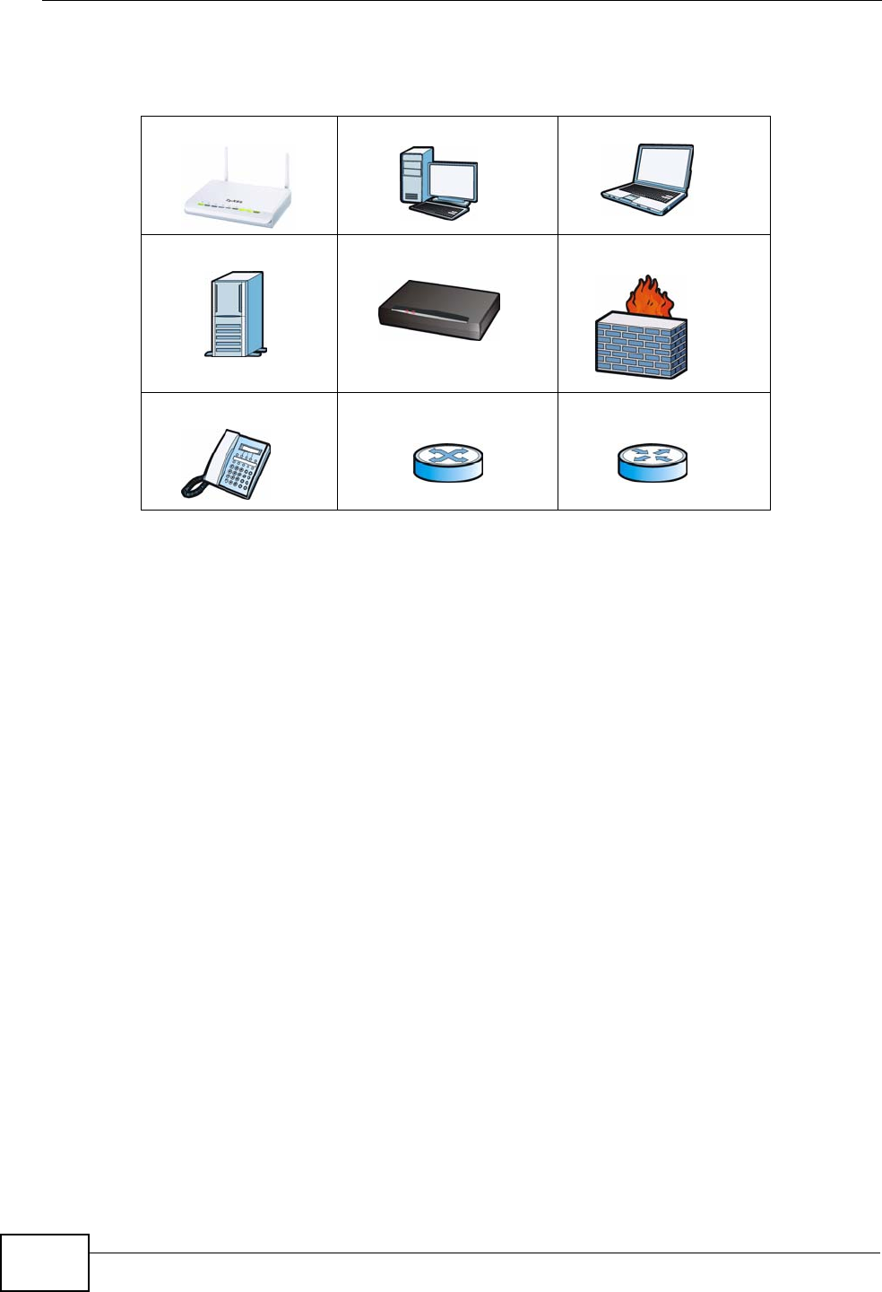
Icons Used in Figures
Figures in this User’s Guide use the following generic icons. The NVG2053 icon is
not an exact representation of your NVG2053.
Graphics in this book may differ slightly from the product due to differences in
operating systems, operating system versions, or if you installed updated
Document Conventions
NVG2053 User’s Guide
6
firmware/software for your device. Every effort has been made to ensure that the
information in this manual is accurate.
NVG2053 Computer Notebook computer
Server Modem Firewall
Telephone Switch Router

Safety Warnings
NVG2053 User’s Guide 7
Safety Warnings
• Do NOT use this product near water, for example, in a wet basement or near a swimming
pool.
• Do NOT expose your device to dampness, dust or corrosive liquids.
• Do NOT store things on the device.
• Do NOT install, use, or service this device during a thunderstorm. There is a remote risk
of electric shock from lightning.
• Connect ONLY suitable accessories to the device.
• Do NOT open the device or unit. Opening or removing covers can expose you to
dangerous high voltage points or other risks. ONLY qualified service personnel should
service or disassemble this device. Please contact your vendor for further information.
• Make sure to connect the cables to the correct ports.
• Place connecting cables carefully so that no one will step on them or stumble over them.
• Always disconnect all cables from this device before servicing or disassembling.
• Use ONLY an appropriate power adaptor or cord for your device.
• Connect the power adaptor or cord to the right supply voltage (for example, 110V AC in
North America or 230V AC in Europe).
• Do NOT allow anything to rest on the power adaptor or cord and do NOT place the
product where anyone can walk on the power adaptor or cord.
• Do NOT use the device if the power adaptor or cord is damaged as it might cause
electrocution.
• If the power adaptor or cord is damaged, remove it from the power outlet.
• Do NOT attempt to repair the power adaptor or cord. Contact your local vendor to order a
new one.
• Do not use the device outside, and make sure all the connections are indoors. There is a
remote risk of electric shock from lightning.
• Do NOT obstruct the device ventilation slots, as insufficient airflow may harm your
device.
• Antenna Warning! This device meets ETSI and FCC certification requirements when using
the included antenna(s). Only use the included antenna(s).
• If you wall mount your device, make sure that no electrical lines, gas or water pipes will
be damaged.
• This CPE product is for indoor use only (utilisation intérieure exclusivement).
Your product is marked with this symbol, which is known as the WEEE mark. WEEE
stands for Waste Electronics and Electrical Equipment. It means that used electrical
and electronic products should not be mixed with general waste. Used electrical and
electronic equipment should be treated separately.

Safety Warnings
NVG2053 User’s Guide
8

Contents Overview
NVG2053 User’s Guide 9
Contents Overview
User’s Guide ...........................................................................................................................19
Getting to Know Your NVG2053 ................................................................................................ 21
Tutorials ..................................................................................................................................... 27
Connection Wizard .................................................................................................................... 49
Introducing the Web Configurator .............................................................................................. 59
Technical Reference ..............................................................................................................67
Status Screens .......................................................................................................................... 69
Monitor ....................................................................................................................................... 75
Broadband ................................................................................................................................. 81
Wireless LAN ............................................................................................................................. 93
LAN .......................................................................................................................................... 121
DHCP Server ........................................................................................................................... 125
Quality of Service (QoS) .......................................................................................................... 131
Network Address Translation (NAT) ........................................................................................ 139
Dynamic DNS .......................................................................................................................... 145
Static Route ............................................................................................................................. 147
Universal Plug-and-Play (UPnP) ............................................................................................. 151
Firewall .................................................................................................................................... 161
Voice ........................................................................................................................................ 167
USB Service ............................................................................................................................ 197
Management ............................................................................................................................ 201
Maintenance ............................................................................................................................ 207
Password ................................................................................................................................. 209
Time ..........................................................................................................................................211
Firmware Upgrade ................................................................................................................... 215
Backup/Restore ....................................................................................................................... 217
Language ................................................................................................................................. 221
Restart ..................................................................................................................................... 223
Troubleshooting ....................................................................................................................... 225
Product Specifications ............................................................................................................. 231

Contents Overview
NVG2053 User’s Guide
10

Table of Contents
NVG2053 User’s Guide 11
Table of Contents
About This User's Guide..........................................................................................................3
Document Conventions............................................................................................................5
Safety Warnings........................................................................................................................7
Contents Overview ...................................................................................................................9
Table of Contents....................................................................................................................11
Part I: User’s Guide................................................................................ 19
Chapter 1
Getting to Know Your NVG2053 ............................................................................................21
1.1 Overview .............................................................................................................................. 21
1.2 Applications ......................................................................................................................... 21
1.2.1 The WPS Button ........................................................................................................ 23
1.3 Ways to Manage the NVG2053 ........................................................................................... 23
1.4 Good Habits for Managing the NVG2053 ............................................................................ 23
1.5 LEDs .................................................................................................................................... 24
1.6 Resetting the NVG2053 ....................................................................................................... 25
1.6.1 Procedure to Use the Reset Button ........................................................................... 25
Chapter 2
Tutorials...................................................................................................................................27
2.1 Overview .............................................................................................................................. 27
2.2 Getting Starting with the NVG2053 ...................................................................................... 27
2.3 How to Make a VoIP Call ..................................................................................................... 28
2.3.1 VoIP Calls With a Registered SIP Account ................................................................ 28
2.4 How to Set up a Secure Wireless Network .......................................................................... 31
2.4.1 Configuring the Wireless Network Settings ................................................................ 32
2.4.2 Using WPS ................................................................................................................. 34
2.4.3 Without WPS ..............................................................................................................38
2.5 How to Access the NVG2053 Using DDNS ......................................................................... 39
2.5.1 Registering a DDNS Account on www.dyndns.org .................................................... 39
2.5.2 Configuring DDNS on Your NVG2053 ........................................................................ 40
2.5.3 Testing the DDNS Setting .......................................................................................... 40
2.6 How to Route Traffic to Another Network Using Static Route .............................................. 41

Table of Contents
NVG2053 User’s Guide
12
2.7 How to Set Up NAT Port Forwarding ................................................................................... 43
2.8 How to Use QoS to Prioritize LAN Traffic ............................................................................ 45
Chapter 3
Connection Wizard .................................................................................................................49
3.1 Overview .............................................................................................................................. 49
3.2 Accessing the Wizard .......................................................................................................... 49
3.3 Connect to Internet .............................................................................................................. 50
3.3.1 Connection Type: PPPoE ........................................................................................... 51
3.3.2 Connection Type: DHCP ............................................................................................ 53
3.3.3 Connection Type: Static IP ......................................................................................... 53
3.4 Router Password ................................................................................................................. 55
3.5 Wireless Security ................................................................................................................. 55
3.5.1 Wireless Security: No Security ................................................................................... 56
3.5.2 Wireless Security: WPA-PSK/WPA2-PSK .................................................................. 57
Chapter 4
Introducing the Web Configurator ........................................................................................59
4.1 Overview .............................................................................................................................. 59
4.2 Accessing the Web Configurator ......................................................................................... 59
4.2.1 Login Screen .............................................................................................................. 60
4.2.2 Password Screen ....................................................................................................... 62
4.3 The Web Configurator Layout .............................................................................................. 63
4.3.1 Navigation Panel ........................................................................................................ 63
4.3.2 Main Window ..............................................................................................................66
4.3.3 Status Bar ................................................................................................................... 66
Part II: Technical Reference .................................................................. 67
Chapter 5
Status Screens........................................................................................................................69
5.1 Overview .............................................................................................................................. 69
5.2 Status Screen ...................................................................................................................... 70
Chapter 6
Monitor.....................................................................................................................................75
6.1 Overview .............................................................................................................................. 75
6.1.1 What You Can Do in this Chapter .............................................................................. 75
6.2 The View Log Screen .......................................................................................................... 75
6.3 The Log Settings Screen .................................................................................................... 76
6.4 The DHCP Table Scren ....................................................................................................77

Table of Contents
NVG2053 User’s Guide 13
6.5 The Packet Statistics Screen ............................................................................................77
6.6 The WLAN Station Status Screen .................................................................................... 79
Chapter 7
Broadband...............................................................................................................................81
7.1 Overview .............................................................................................................................. 81
7.1.1 What You Can Do in this Chapter .............................................................................. 81
7.2 What You Need To Know ..................................................................................................... 81
7.3 The Broadband Screen ......................................................................................................83
7.3.1 Broadband Configuration ........................................................................................... 84
7.3.2 PPPoE Encapsulation ................................................................................................ 86
7.4 Technical Reference ............................................................................................................ 90
Chapter 8
Wireless LAN...........................................................................................................................93
8.1 Overview .............................................................................................................................. 93
8.1.1 What You Can Do in this Chapter .............................................................................. 94
8.2 What You Need to Know ......................................................................................................94
8.3 General Wireless LAN Screen ............................................................................................ 97
8.3.1 No Security ................................................................................................................. 98
8.3.2 WEP Encryption ......................................................................................................... 99
8.3.3 WPA(2)-PSK ............................................................................................................ 101
8.3.4 WPA(2) Authentication ............................................................................................. 102
8.4 MAC Filter .......................................................................................................................... 104
8.5 Wireless LAN Advanced Screen ....................................................................................... 105
8.6 Quality of Service (QoS) Screen ....................................................................................... 107
8.7 WPS Screen ...................................................................................................................... 107
8.8 WPS Station Screen .......................................................................................................... 109
8.9 Scheduling Screen .............................................................................................................110
8.10 Technical Reference ......................................................................................................... 111
8.10.1 Additional Wireless Terms .......................................................................................111
8.10.2 Wireless Security Overview ....................................................................................111
8.10.3 WiFi Protected Setup ..............................................................................................114
Chapter 9
LAN.........................................................................................................................................121
9.1 Overview ............................................................................................................................ 121
9.2 What You Can Do in this Chapter ...................................................................................... 121
9.3 What You Need To Know ................................................................................................... 122
9.3.1 Multicast ................................................................................................................... 122
9.4 LAN IP Screen ................................................................................................................... 123
9.5 LAN Advanced Screen ...................................................................................................... 124

Table of Contents
NVG2053 User’s Guide
14
Chapter 10
DHCP Server..........................................................................................................................125
10.1 Overview .......................................................................................................................... 125
10.1.1 What You Can Do in this Chapter .......................................................................... 125
10.2 What You Need to Know .................................................................................................. 125
10.2.1 DHCP ..................................................................................................................... 125
10.2.2 IP Pool Setup ......................................................................................................... 125
10.3 General Screen ............................................................................................................... 126
10.4 Advanced Screen ......................................................................................................... 126
10.5 Client List Screen ............................................................................................................ 128
Chapter 11
Quality of Service (QoS).......................................................................................................131
11.1 Overview ......................................................................................................................... 131
11.1.1 What You Can Do in this Chapter ........................................................................... 131
11.2 The Quality of Service General Screen .......................................................................... 132
11.2.1 QoS Class Edit ...................................................................................................... 134
11.3 Technical Reference ........................................................................................................ 135
Chapter 12
Network Address Translation (NAT)....................................................................................139
12.1 Overview ....................................................................................................................... 139
12.1.1 What You Can Do in this Chapter .......................................................................... 140
12.2 The General NAT Screen ................................................................................................ 140
12.3 The NAT Port Forwarding Screen .................................................................................. 140
12.3.1 Port Forwarding Edit Screen ................................................................................. 142
Chapter 13
Dynamic DNS ........................................................................................................................145
13.1 Overview ......................................................................................................................... 145
13.1.1 What You Can Do in this Chapter .......................................................................... 145
13.2 What You Need To Know ................................................................................................. 145
13.3 The Dynamic DNS Screen ............................................................................................ 146
Chapter 14
Static Route...........................................................................................................................147
14.1 Overview ....................................................................................................................... 147
14.1.1 What You Can Do in this Chapter .......................................................................... 147
14.2 The IP Static Route Screen ............................................................................................ 148
14.2.1 Static Route Edit ................................................................................................... 149
Chapter 15
Universal Plug-and-Play (UPnP)..........................................................................................151

Table of Contents
NVG2053 User’s Guide 15
15.1 Overview ......................................................................................................................... 151
15.1.1 What You Can Do in this Chapter .......................................................................... 151
15.2 What You Need to Know .................................................................................................. 151
15.3 The UPnP Screen ............................................................................................................ 152
15.4 Installing UPnP in Windows ............................................................................................. 153
15.4.1 Windows 7 .............................................................................................................. 153
15.4.2 Windows XP ........................................................................................................... 154
15.5 Using UPnP in Windows XP ............................................................................................ 155
15.5.1 Auto-discover Your UPnP-enabled Network Device .............................................. 156
15.5.2 Web Configurator Easy Access ............................................................................. 158
Chapter 16
Firewall...................................................................................................................................161
16.1 Overview ........................................................................................................................ 161
16.1.1 What You Can Do in this Chapter .......................................................................... 161
16.2 What You Need To Know ................................................................................................. 161
16.3 The General Firewall Screen ........................................................................................ 162
16.4 The Services Screen ....................................................................................................163
16.4.1 Configuring Firewall Rules ................................................................................... 164
Chapter 17
Voice.......................................................................................................................................167
17.1 Overview .......................................................................................................................... 167
17.1.1 What You Can Do in this Chapter .......................................................................... 167
17.1.2 What You Need to Know ........................................................................................ 168
17.2 Before You Begin ............................................................................................................. 168
17.3 The SIP Service Provider Screen ................................................................................... 169
17.4 The SIP Account Screen ................................................................................................ 172
17.4.1 SIP Account Edit .................................................................................................. 173
17.4.2 Dial Plan Rules ....................................................................................................... 176
17.5 The Phone Device Screen .............................................................................................. 177
17.5.1 The Phone Device Edit Screen ............................................................................. 178
17.6 The Phone Region Screen ............................................................................................. 180
17.7 The Speed Dial Screen .................................................................................................... 180
17.7.1 The Speed Dial Edit Screen .................................................................................. 182
17.8 The PSTN call through Screen ....................................................................................... 182
17.9 Technical Reference ........................................................................................................ 183
17.9.1 Quality of Service (QoS) ........................................................................................ 191
17.9.2 Phone Services Overview ...................................................................................... 192
Chapter 18
USB Service...........................................................................................................................197
18.1 Overview .......................................................................................................................... 197

Table of Contents
NVG2053 User’s Guide
16
18.1.1 What You Can Do in this Chapter .......................................................................... 197
18.2 What You Need to Know .................................................................................................. 197
18.3 Before You Begin ............................................................................................................. 198
18.4 The 3G Connection Setup Screen ................................................................................... 198
Chapter 19
Management..........................................................................................................................201
19.1 Overview .......................................................................................................................... 201
19.1.1 What You Can Do in this Chapter .......................................................................... 201
19.2 What You Need To Know ................................................................................................. 201
19.3 The TR-069 Screen .........................................................................................................202
19.4 The WWW Screen ........................................................................................................... 204
19.5 The Telnet Screen ........................................................................................................... 204
19.6 The ICMP Screen ............................................................................................................ 205
Chapter 20
Maintenance ..........................................................................................................................207
20.1 Overview .......................................................................................................................... 207
20.2 What You Can Do ............................................................................................................ 207
20.3 General Screen .............................................................................................................. 207
Chapter 21
Password...............................................................................................................................209
21.1 Overview .......................................................................................................................... 209
21.1.1 What You Can Do in this Chapter .......................................................................... 209
21.2 Password Screen ............................................................................................................ 209
Chapter 22
Time........................................................................................................................................ 211
22.1 Overview ...........................................................................................................................211
22.1.1 What You Can Do in this Chapter ...........................................................................211
22.2 Time Setting Screen ........................................................................................................ 212
Chapter 23
Firmware Upgrade ................................................................................................................215
23.1 Overview .......................................................................................................................... 215
23.1.1 What You Can Do in this Chapter .......................................................................... 215
23.2 Firmware Upgrade Screen .............................................................................................. 215
Chapter 24
Backup/Restore.....................................................................................................................217
24.1 Overview .......................................................................................................................... 217
24.1.1 What You Can Do in this Chapter .......................................................................... 217

Table of Contents
NVG2053 User’s Guide 17
24.2 Backup/Restore Screen ................................................................................................... 218
Chapter 25
Language...............................................................................................................................221
25.1 Overview .......................................................................................................................... 221
25.2 What You Can Do ............................................................................................................ 221
25.3 The Language Screen ..................................................................................................... 221
Chapter 26
Restart....................................................................................................................................223
26.1 Overview .......................................................................................................................... 223
26.2 What You Can Do ............................................................................................................ 223
26.3 The Restart Screen ......................................................................................................... 223
Chapter 27
Troubleshooting....................................................................................................................225
27.1 Power, Hardware Connections, and LEDs ...................................................................... 225
27.2 NVG2053 Access and Login ........................................................................................... 226
27.3 Internet Access ................................................................................................................ 228
27.4 Resetting the NVG2053 to Its Factory Defaults ............................................................... 229
27.5 Wireless Router/AP Troubleshooting ............................................................................... 230
Chapter 28
Product Specifications.........................................................................................................231
Appendix A Pop-up Windows, JavaScripts and Java Permissions......................................235
Appendix B Setting Up Your Computer’s IP Address...........................................................247
Appendix C Wireless LANs ..................................................................................................275
Appendix D Legal Information..............................................................................................291
Appendix E Open Software Announcements .......................................................................295
Index.......................................................................................................................................323

Table of Contents
NVG2053 User’s Guide
18

19
PART I
User’s Guide

20

NVG2053 User’s Guide 21
CHAPTER 1
Getting to Know Your NVG2053
1.1 Overview
This chapter introduces the main features and applications of the NVG2053.
The NVG2053 extends the range of your existing wired network without additional
wiring, providing easy network access to mobile users. You can set up a wireless
network with other IEEE 802.11b/g/n compatible devices.
The NVG2053 supports Voice over IP (VoIP) technology to allow you to use an
analog telephone to make phone calls over the Internet.
The NVG2053 also supports 3G, which allows you to insert a 3G wireless adapter
in the USB port and use the 3G WAN connection as your WAN or a backup to
enhance network reliability.
You can enable NAT and use Quality of Service (QoS) to efficiently manage traffic
on your network by giving priority to certain types of traffic and/or to particular
computers.
1.2 Applications
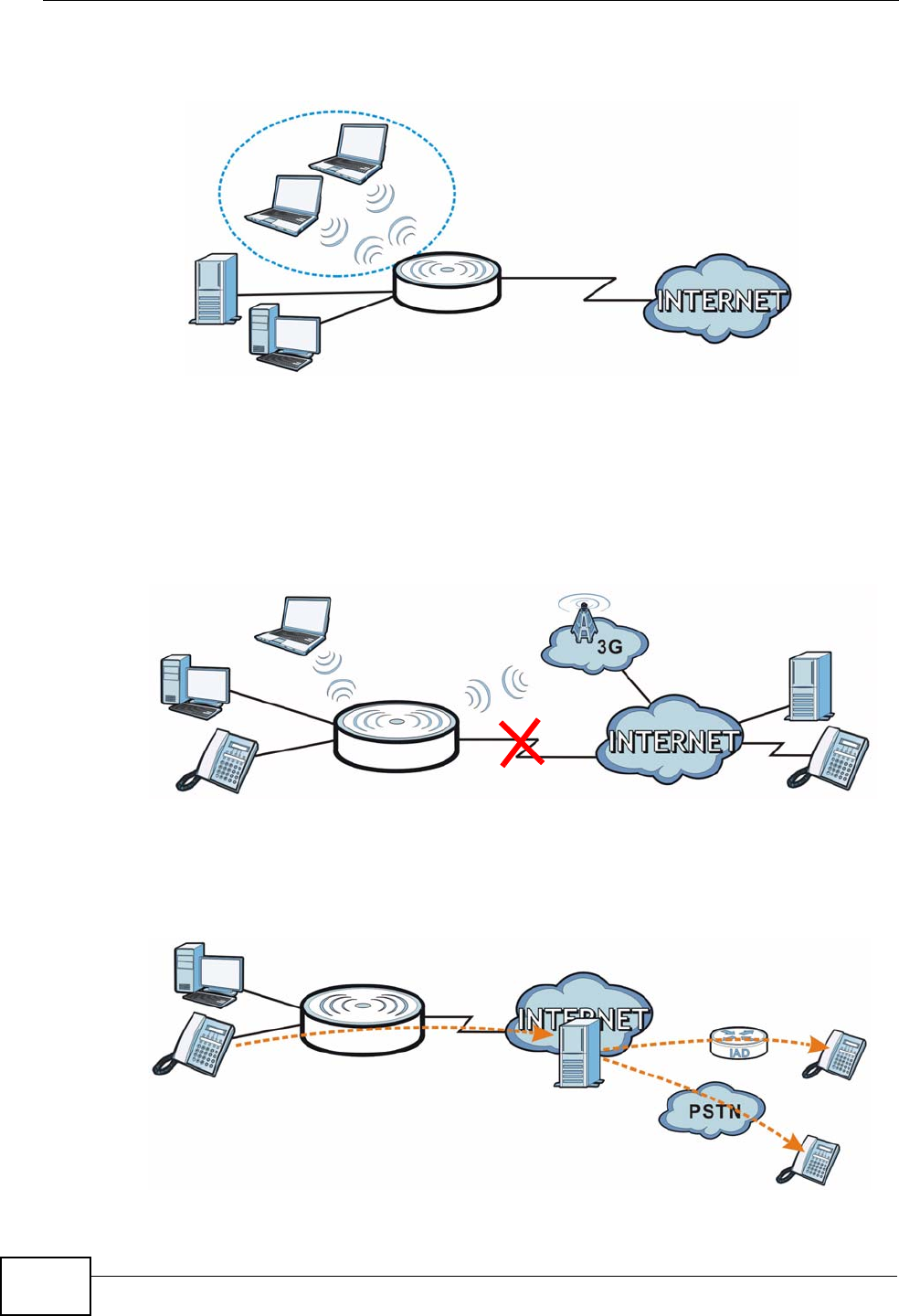
Your can create the following networks using the NVG2053:
•LAN. You can connect network devices via the Ethernet ports of the NVG2053
so that they can communicate with each other and access the Internet.
•Wireless. Wireless clients can connect to the NVG2053 to access network
resources.
Chapter 1 Getting to Know Your NVG2053
NVG2053 User’s Guide
22
•WAN. Connect to a broadband modem/router for Internet access.
Figure 1 NVG2053 Networks
•3G WAN. The USB port allows you to wirelessly connect to a 3G netowk to get
Internet access by attaching a 3G wireless adapter. You must leave the Ethernet
WAN port unconnected and attached a 3G wireless card to use 3G as your WAN.
You can also have the NVG2053 use the 3G WAN connection as a backup. That
means the NVG2053 switches to the 3G wireless WAN connection after the
wired Ethernet WAN connection fails. The NVG2053 automatically changes back
to use the wired Ethernet WAN connection when it is available.
Figure 2 Internet Access Application: 3G WAN
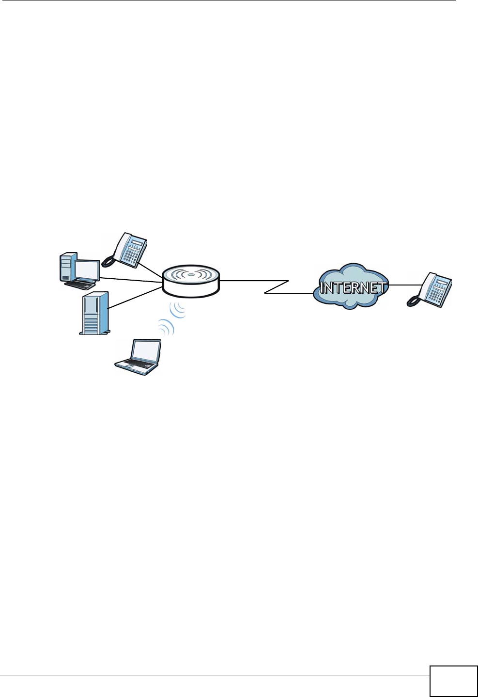
•VoIP Internet Calls. You can register up to two SIP (Session Initiation
Protocol) accounts and use the NVG2053 to make and receive VoIP telephone
calls. The NVG2053 sends your call to a VoIP service provider’s SIP server (A)
which forwards your calls to either VoIP or PSTN phones.
Figure 3 VoIP Application
WAN
WLAN
LAN
A

Chapter 1 Getting to Know Your NVG2053
NVG2053 User’s Guide 23
1.2.1 The WPS Button
You can use the WPS button ( ) on the top panel of the NVG2053 to activate
WPS in order to quickly set up a wireless network with strong security.
1Make sure the POWER LED is on (not blinking).
2Press the WPS button for more than three seconds and release it. Press the WPS
button on another WPS-enabled device within range of the NVG2053.
Note: You must activate WPS in the NVG2053 and in another wireless device within
two minutes of each other. See Section 8.10.3 on page 114 for more
information.
1.3 Ways to Manage the NVG2053
Use any of the following methods to manage the NVG2053.
• Web Configurator. This is recommended for everyday management of the
NVG2053 using a (supported) web browser.
• Wireless switch. You can use the built-in switch of the NVG2053 to turn the
wireless function on and off without opening the Web Configurator.
• WPS (Wi-Fi Protected Setup) button. You can use the WPS button or the WPS
section of the Web Configurator to set up a wireless network with your ZyXEL
Device.
• TR-069. This is an auto-configuration server used to remotely configure your
device.
1.4 Good Habits for Managing the NVG2053
Do the following things regularly to make the NVG2053 more secure and to
manage the NVG2053 more effectively.
• Change the password. Use a password that’s not easy to guess and that consists
of different types of characters, such as numbers and letters.
• Write down the password and put it in a safe place.
• Back up the configuration (and make sure you know how to restore it).
Restoring an earlier working configuration may be useful if the device becomes
unstable or even crashes. If you forget your password, you will have to reset the
NVG2053 to its factory default settings. If you backed up an earlier
configuration file, you would not have to totally re-configure the NVG2053. You
could simply restore your last configuration.
Chapter 1 Getting to Know Your NVG2053
NVG2053 User’s Guide
24
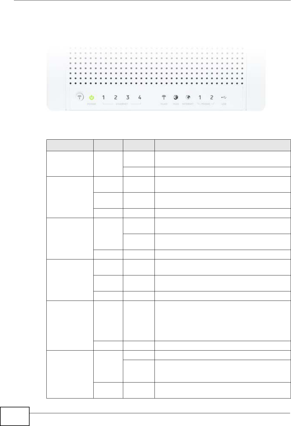
1.5 LEDs
Figure 4 Top Panel
The following table describes the LEDs and the WLAN button.
Table 1 Top Panel LEDs and WPS Button
LED COLOR STATUS DESCRIPTION
POWER Green On The NVG2053 is receiving power and functioning
properly.
Off The NVG2053 is not receiving power.
ETHERNET 1-4 Green On The NVG2053 has a successful 10/100/1000MB
Ethernet connection.
Blinking The NVG2053 is sending/receiving data through
the LAN.
Off The LAN is not connected.
WLAN Green On The NVG2053 is ready, but is not sending/
receiving data through the wireless LAN.
Blinking The NVG2053 is sending/receiving data through
the wireless LAN.
Off The wireless LAN is not ready or has failed.
WAN Green On The NVG2053 has a successful 10/100/1000MB
WAN connection.
Blinking The NVG2053 is sending/receiving data through
the WAN.
Off The WAN connection is not ready, or has failed.
INTERNET Green On The NVG2053 has an IP connection.
Your device has a WAN IP address (either static
or assigned by a DHCP server), PPP negotiation
was successfully completed (if used) and the DSL
connection is up.
Off The NVG2053 does not have an IP connection.
PHONE 1/2 Green On A SIP account is registered for the phone port.
Blinking A telephone connected to the phone port has its
receiver off of the hook or there is an incoming
call.
Off The phone port does not have a SIP account
registered.

Chapter 1 Getting to Know Your NVG2053
NVG2053 User’s Guide 25
1.6 Resetting the NVG2053
If you forget your password or IP address, or you cannot access the Web
Configurator, you will need to use the RESET button at the side of the NVG2053 to
reload the factory-default configuration file. This means that you will lose all
configurations that you had previously saved, the password will be reset to “1234”
and the IP address will be reset to “192.168.1.1”.
1.6.1 Procedure to Use the Reset Button
1Make sure the power LED is on.
2Press the RESET button for longer than ten seconds to set the NVG2053 back to
its factory-default configurations.
USB Green On The NVG2053 recognizes a USB connection.
Blinking The NVG2053 is sending/receiving data to /from
the USB device connected to it.
Off The NVG2053 does not detect a USB connection.
Table 1 Top Panel LEDs and WPS Button
LED COLOR STATUS DESCRIPTION

Chapter 1 Getting to Know Your NVG2053
NVG2053 User’s Guide
26

NVG2053 User’s Guide 27
CHAPTER 2
Tutorials
2.1 Overview
This chapter describes:
•How to Make a VoIP Call (see page 28).
•How to Set up a Secure Wireless Network (see page 31).
•How to Access the NVG2053 Using DDNS (see page 39)
•How to Route Traffic to Another Network Using Static Route (see page 41)
•How to Set Up NAT Port Forwarding (see page 43)
•How to Use QoS to Prioritize LAN Traffic (see page 45)
Note: The tutorials featured in this chapter require a basic understanding of
connecting to and using the Web Configurator on your NVG2053. For details,
see the included Quick Start Guide. For field descriptions of individual screens,
see the related technical reference in this User's Guide.
2.2 Getting Starting with the NVG2053
This quick overview provides pointers on where in this User’s Guide you can go to
get started with configuring and using the NVG2053.
Your NVG2053 may have come pre-configured from your ISP. If
such is the case, changing any network settings may affect your
ability to get online or connect to other computers on your
network.
1Install the device as described in the included Quick Start Guide.
2Connect and login to the Web Configurator at its default IP address as described in
Section 4.2 on page 59. This is where you configure all available settings related
to your device and its network connections. You will most likely need to connect to
the NVG2053 directly from your computer rather than over an existing network,
since the device’s default IP address won’t match that network’s existing topology.
Chapter 2 Tutorials
NVG2053 User’s Guide
28
3Once you’re in the Web Configurator, you can assign the NVG2053 a new Local
Area Network (LAN) IP address. This allows you to position in your LAN topology
where it is most beneficial to you. See Section 9.4 on page 123 for details.
4If you were given settings to configure the NVG2053’s WAN connection, then you
can do so in Section 7.3 on page 83.
5Finally, if you have a SIP account and want to place phone calls over the Internet,
see Section 2.3 on page 28.
2.3 How to Make a VoIP Call
The NVG2053 allows you to plug an analog phone into it and place calls over the
Internet to another VoIP device as if you were using an IP Phone or a SIP phone.
Making Internet phone calls requries that first have a SIP account set up with
either your ISP (if they provide such a service) or a third-party SIP provider.
2.3.1 VoIP Calls With a Registered SIP Account
To use a registered SIP account, you should have applied for a SIP account with
the VoIP service provider and got account information from your provider.
This section shows you examples of how to register your SIP account on the
NVG2053 and make Internet calls.
The following table shows the SIP account and SIP server address provided by
your service provider.
2.3.1.1 SIP Account Registration
Follow the steps below to register and activate your SIP account.
1Make sure your NVG2053 is connected to the Internet.
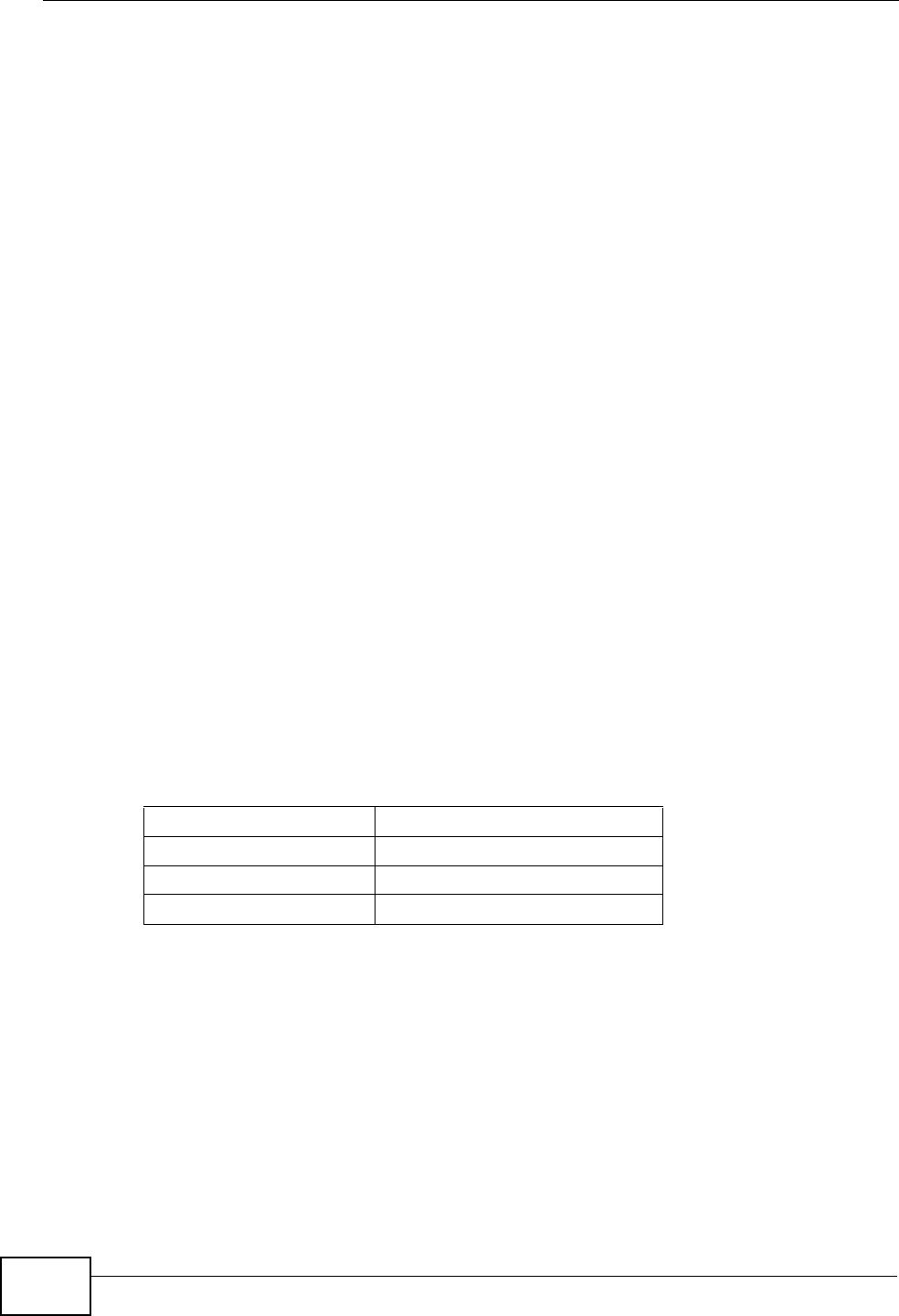
2Open the web configurator and go to VoIP > SIP.
3Select the SIP service provider profile you want to configure and give it a name
(“SIPSP-1” for example).
SIP Account 12345678@voipprovider.com
SIP Server Address 127.1.2.3
User Name username123
Password password123
Chapter 2 Tutorials
NVG2053 User’s Guide 29
4Enter the SIP server address (“127.1.2.3” in this example).
5Repeat the SIP server address in the REGISTER Server Address field.
6Enter the SIP server domain (“voipprovider.com” in this example) which is the part
after the @ symbol in your SIP account. Click Apply.
7Click VoIP > SIP > SIP Account to enter your SIP account information.
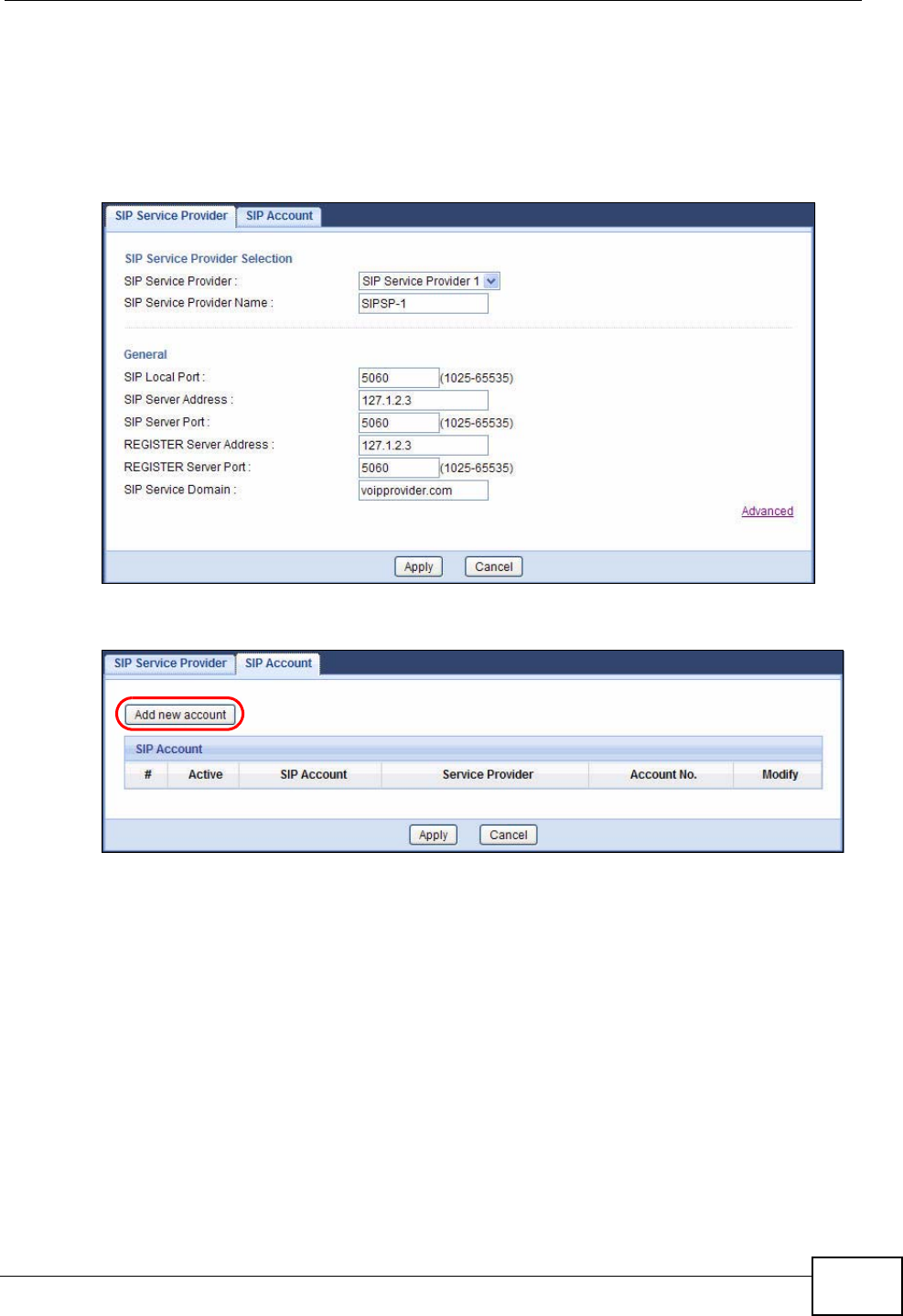
8The NVG2053 allows you to set up multiple SIP accounts. Click the Add new
account button and then select SIP1 to configure the first SIP account.
9Select the name of the SIP service provider profile you just configured.
10 Select the checkbox to enable the SIP account on the NVG2053. If you do not
select this option, then you cannot use the settings configured here for the
selected SIP account.
11 Enter the SIP number (“12345678” in this example) which is the part before the @
symbol in your SIP account.
Chapter 2 Tutorials
NVG2053 User’s Guide
30
12 Enter your user name and password. Click Apply to save your changes.
13 The NVG2053 automatically tries to register your SIP account after you click
Apply. Go to the Status screen, the Status of the FXS1 interface should be
Registered. Check the PHONE LED on the device’s top panel.
2.3.1.2 Analog Phone Configuration
Next, you must configure your Phone settings to bind your newly configured SIP
settings to a single phone.
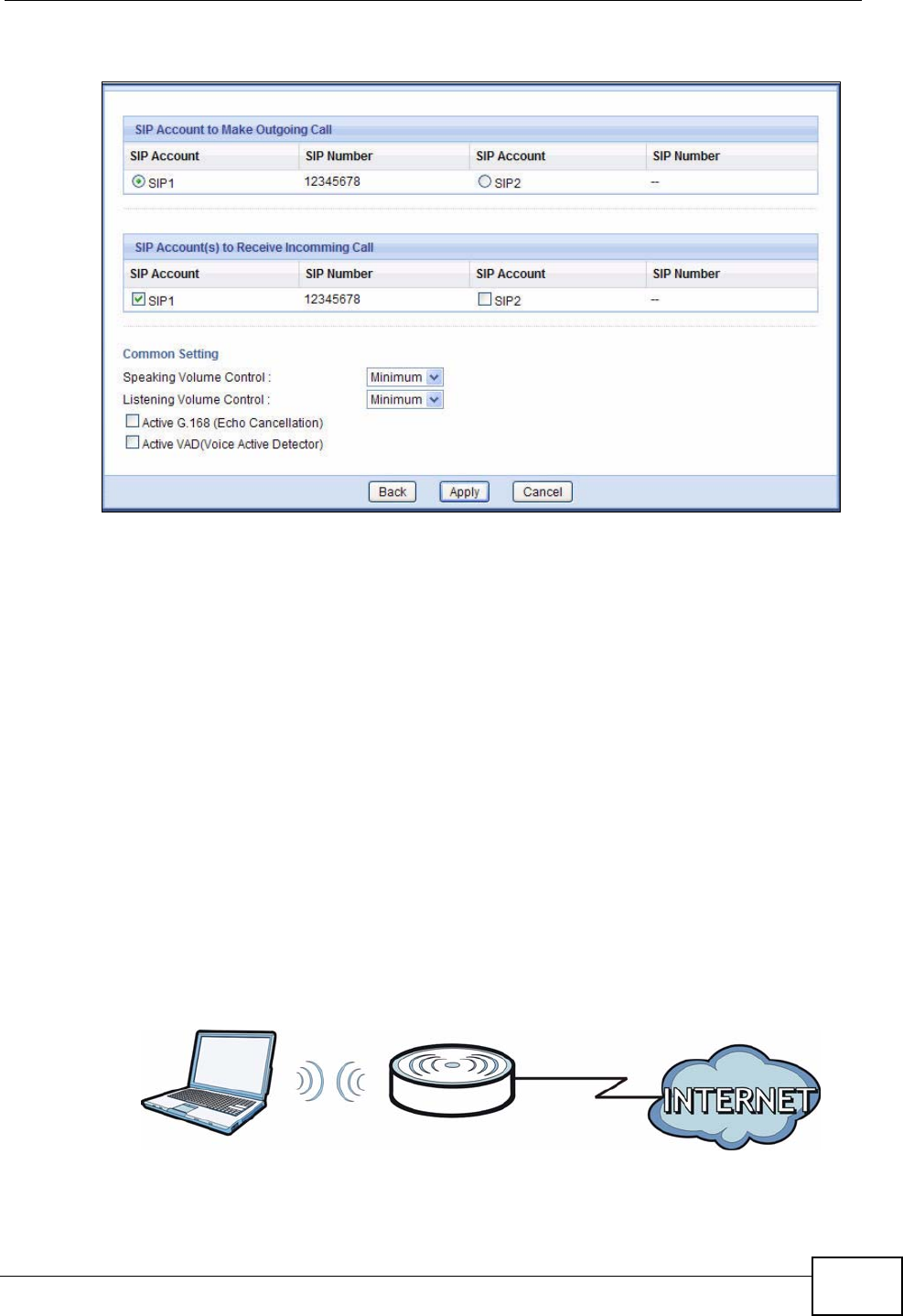
1Click VoIP > Phone to open the Phone Device screen.
2Click the Edit icon of the first entry to configure the first phone port. The phone
you choose corresponds to one of two phones physically connected to your
NVG2053.
3Select SIP1 in the SIP Account field of the SIP Account to Make Outgoing
Call section to have the phone (connected to the first phone port) use the
registered SIP1 account to make outgoing calls. This means any call sent to the
selected SIP account is forwarded to the phone port configured here.
4Select the SIP1 checkbox in the SIP Account(s) to Receive Incoming Call
section to have the phone (connected to the first phone port) receive phone calls
for the SIP1 account.
Chapter 2 Tutorials
NVG2053 User’s Guide 31
5Click Apply to save your changes.
2.3.1.3 Making a VoIP Call
1Connect a telephone to the first phone port on the NVG2053.
2Make sure the NVG2053 is on and connected to the Internet.
3Pick up the handset and hear a dial tone.
4Dial the SIP phone number you want to call.
2.4 How to Set up a Secure Wireless Network
You want to set up a wireless network so that you can use a notebook to access
the Internet wirelessly. In this wireless network, the NVG2053 serves as an access
point (AP), and the notebook with a wireless network card or USB/PCI adapter is
the wireless client. The wireless client can access the Internet through the AP.
Chapter 2 Tutorials
NVG2053 User’s Guide
32
You have to configure the wireless network settings on the NVG2053. Then you
can set up a wireless network using WPS (Section 2.4.2 on page 34) or manual
configuration (Section 2.4.3 on page 38).
2.4.1 Configuring the Wireless Network Settings
This example uses the following parameters to set up a wireless network.
Follow the steps below to configure the wireless settings on the NVG2053.
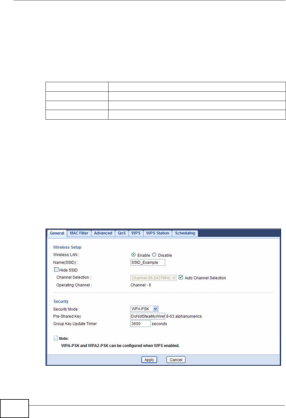
1Open the Network > Wireless LAN > General screen in the NVG2053’s web
configurator. Configure the screen using the provided parameters (see page 32).
2Make sure the Enable option is selected.
3Enter “SSID_Example” as the SSID and select Auto Channel Selection to have
the NVG2053 automatically determine a channel which is not used by another AP.
4Set security mode to WPA-PSK and enter “DoNotStealMyWirelessNetwork” in the
Pre-Shared Key field. Click Apply.
SSID SSID_Example
Security Mode WPA-PSK
Pre-Shared Key DoNotStealMyWirelessNetwork
Operating Mode IEEE 802.11b/g/n (Mixed)
Chapter 2 Tutorials
NVG2053 User’s Guide 33
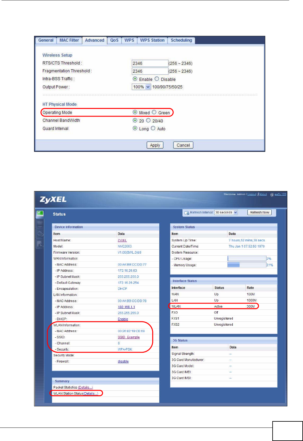
5Go to the Wireless LAN > Advanced screen, and make sure the Operating
Mode is set to Mixed. Click Apply.
6Open the Status screen.Verify your wireless and wireless security settings under
Device Information and check if the WLAN connection is up under Interface
Status.

Chapter 2 Tutorials
NVG2053 User’s Guide
34
7You can now use the WPS feature to establish a wireless connection between his
notebook and the NVG2053 (see Section 2.4.2 on page 34). You can also use the
notebook’s wireless client to search for the NVG2053 (see Section 2.4.3 on page
38).
8Click the WLAN Station Status hyperlink in the Status screen. You can see if
any wireless client has connected to the NVG2053.
2.4.2 Using WPS
This section shows you how to set up a wireless network using WPS. It uses the
NVG2053 as the AP and ZyXEL NWD210N as the wireless client which connects to
the notebook.
Note: The wireless client must be a WPS-aware device (for example, a WPS USB
adapter or PCMCIA card).
There are two WPS methods to set up the wireless client settings:
•Push Button Configuration (PBC) - simply press a button. This is the easier
of the two methods.
•PIN Configuration - configure a Personal Identification Number (PIN) on the
NVG2053. A wireless client must also use the same PIN in order to download the
wireless network settings from the NVG2053.
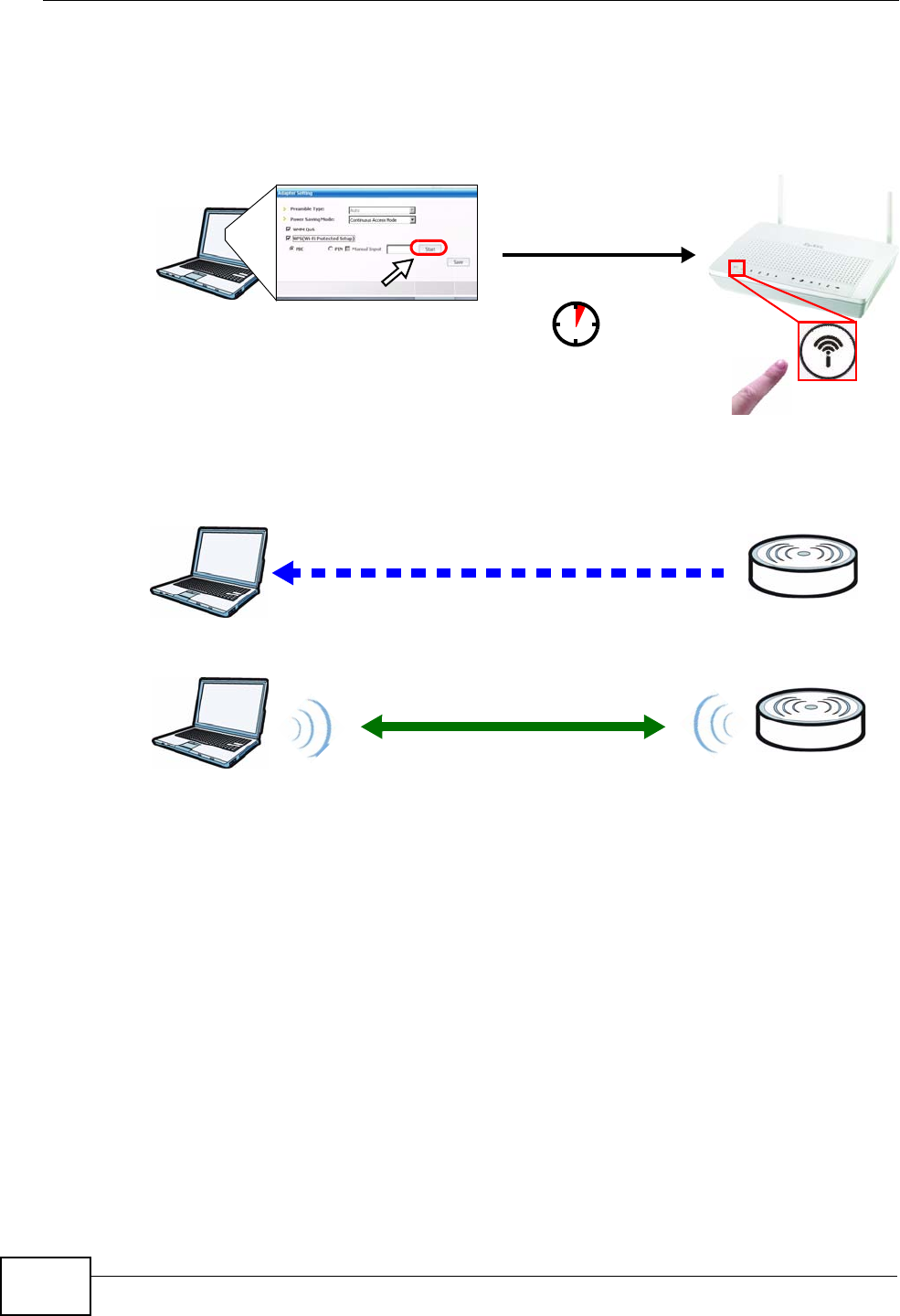
Push Button Configuration (PBC)
1Make sure that your NVG2053 is turned on and your notebook is within the cover
range of the wireless signal.
2Make sure that you have installed the wireless client driver and utility in your
notebook.
3Press the WPS button on your notebook within range of the NVG2053.
Chapter 2 Tutorials
NVG2053 User’s Guide 35
4The wireless LAN of the NVG2053 is enabled by default, so the WLAN LED lights
green. If not, push the WLAN switch to the ON position on the rear panel. When
the LED turns green, the wireless LAN is on. Then press the WPS button for more
than three seconds and release it.
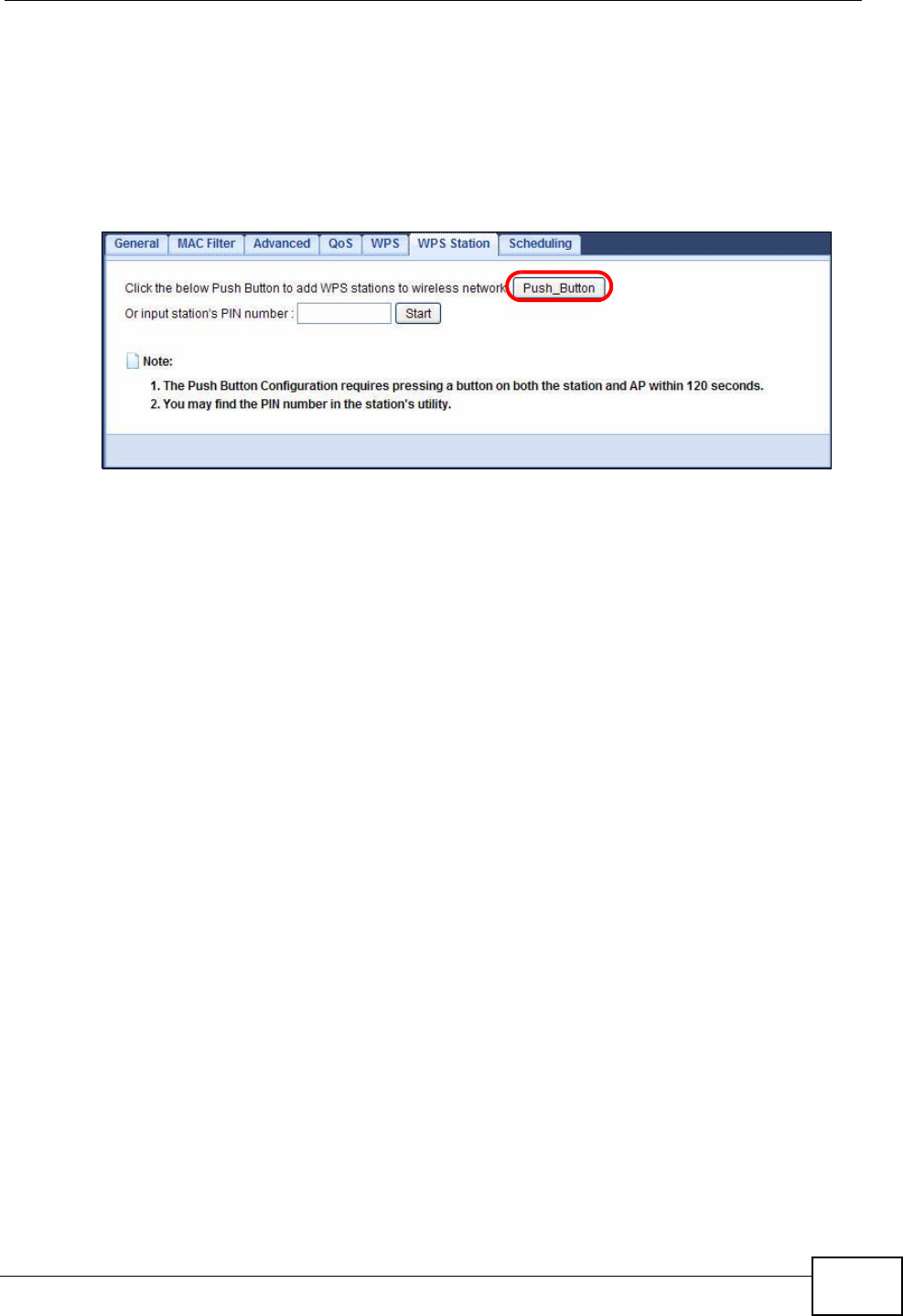
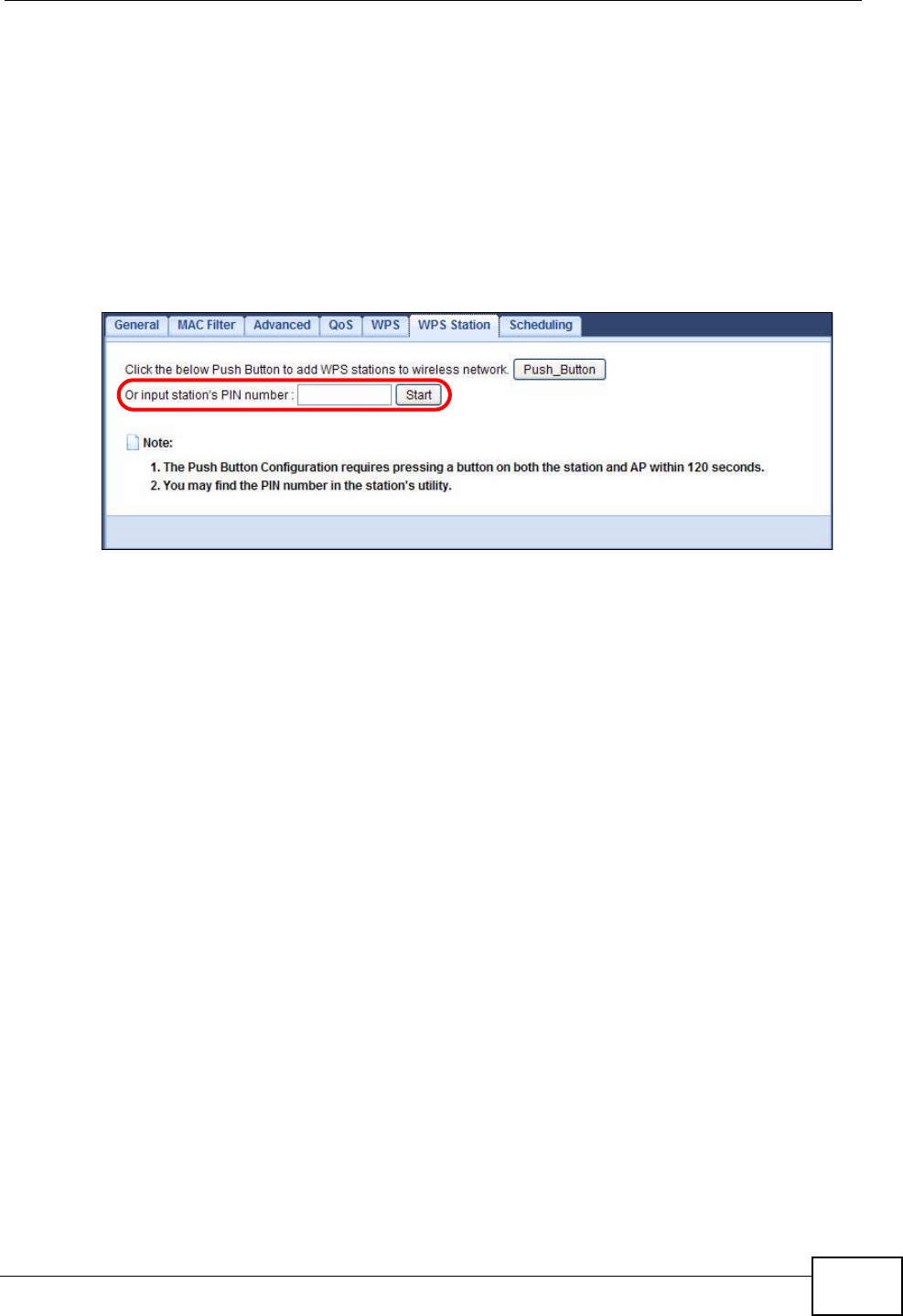
5Alternatively, you may log into NVG2053’s web configurator and click the Push
Button in the Network > Wireless LAN > WPS Station screen.
Note: Your NVG2053 has a WPS button located on its top panel as well as a WPS
button in its configuration utility. Both buttons have exactly the same function:
you can use one or the other.
Note: It doesn’t matter which button is pressed first. You must press the second
button within 120 seconds of pressing the first one.
Chapter 2 Tutorials
NVG2053 User’s Guide
36
The following figure shows you an example of how to set up a wireless network
and its security by pressing a button on both NVG2053 and wireless client.
Example WPS Process: PBC Method
Wireless Client Access Point
SECURITY INFO
COMMUNICATION
WITHIN 120 SECONDS
Press and hold for
more than 3 seconds
Chapter 2 Tutorials
NVG2053 User’s Guide 37
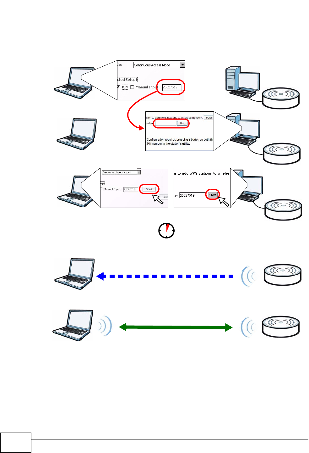
PIN Configuration
When you use the PIN configuration method, you need to use both the NVG2053’s
web configurator and the wireless client’s utility.
1Launch your wireless client’s configuration utility. Go to the WPS settings and
select the PIN method to get a PIN number.
2Enter the PIN number in the PIN field in the Network > Wireless LAN > WPS
Station screen on the NVG2053.
3Click the Start buttons (or the button next to the PIN field) on both the wireless
client utility screen and the NVG2053’s WPS Station screen within two minutes.
The NVG2053 authenticates the wireless client and sends the proper configuration
settings to the wireless client. This may take up to two minutes. The wireless
client is then able to communicate with the NVG2053 securely.
Chapter 2 Tutorials
NVG2053 User’s Guide
38
The following figure shows you how to set up a wireless network and its security
on a NVG2053 and a wireless client by using PIN method.
Example WPS Process: PIN Method
2.4.3 Without WPS
Use the wireless adapter’s utility installed on the notebook to search for the
“SSID_Example” SSID. Then enter the “DoNotStealMyWirelessNetwork” pre-
shared key to establish an wireless Internet connection.
Authentication by PIN
SECURITY INFO
WITHIN 2 MINUTES
Wireless Client
Access Point
COMMUNICATION
Chapter 2 Tutorials
NVG2053 User’s Guide 39
Note: The NVG2053 supports IEEE 802.11b, IEEE 802.11g and IEEE 802.11n
wireless clients. Make sure that your notebook or computer’s wireless adapter
supports one of these standards.
2.5 How to Access the NVG2053 Using DDNS
If you connect your NVG2053 to the Internet and it uses a dynamic WAN IP
address, it is inconvenient for you to manage the device from the Internet. The
NVG2053’s WAN IP address changes dynamically. Dynamic DNS (DDNS) allows
you to access the NVG2053 using a domain name.
To use this feature, you have to apply for DDNS service at www.dyndns.org.
This tutorial shows you how to:
•Registering a DDNS Account on www.dyndns.org
•Configuring DDNS on Your NVG2053
•Testing the DDNS Setting
Note: If you have a private WAN IP address, then you cannot use DDNS.
2.5.1 Registering a DDNS Account on www.dyndns.org
1Open a browser and type http://www.dyndns.org.
2Apply for a user account. This tutorial uses “UserName1” and “12345” as the
username and password.
3Log into www.dyndns.org using your account.
4Add a new DDNS host name. This tutorial uses the following settings as an
example.
• Hostname: zyxelrouter.dyndns.org
• Service Type: Host with IP address
w.x.y.z a.b.c.d
http://zyxelrouter.dyndns.org
A
Chapter 2 Tutorials
NVG2053 User’s Guide
40
• IP Address: Enter the WAN IP address that your NVG2053 is currently using.
You can find the IP address on the NVG2053’s Web Configurator Status page.
Then you will need to configure the same account and host name on the NVG2053
later.
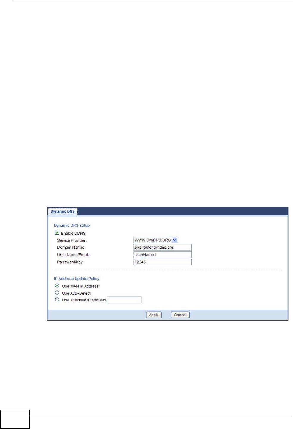
2.5.2 Configuring DDNS on Your NVG2053
1Log into the NVG2053's advanced mode.
2Configure the following settings in the Network > Dynamic DNS screen.
2a Select Enable DDNS.
2b Select WWW.DynDNS.ORG in the Service Provider field.
2c Type “zyxelrouter.dyndns.org” in the Domain Name field.
2d Enter the user name (“UserName1” for example) and password (“12345” for
example).
2e Select Use WAN IP Address for the IP address update policy.
2f Click Apply.
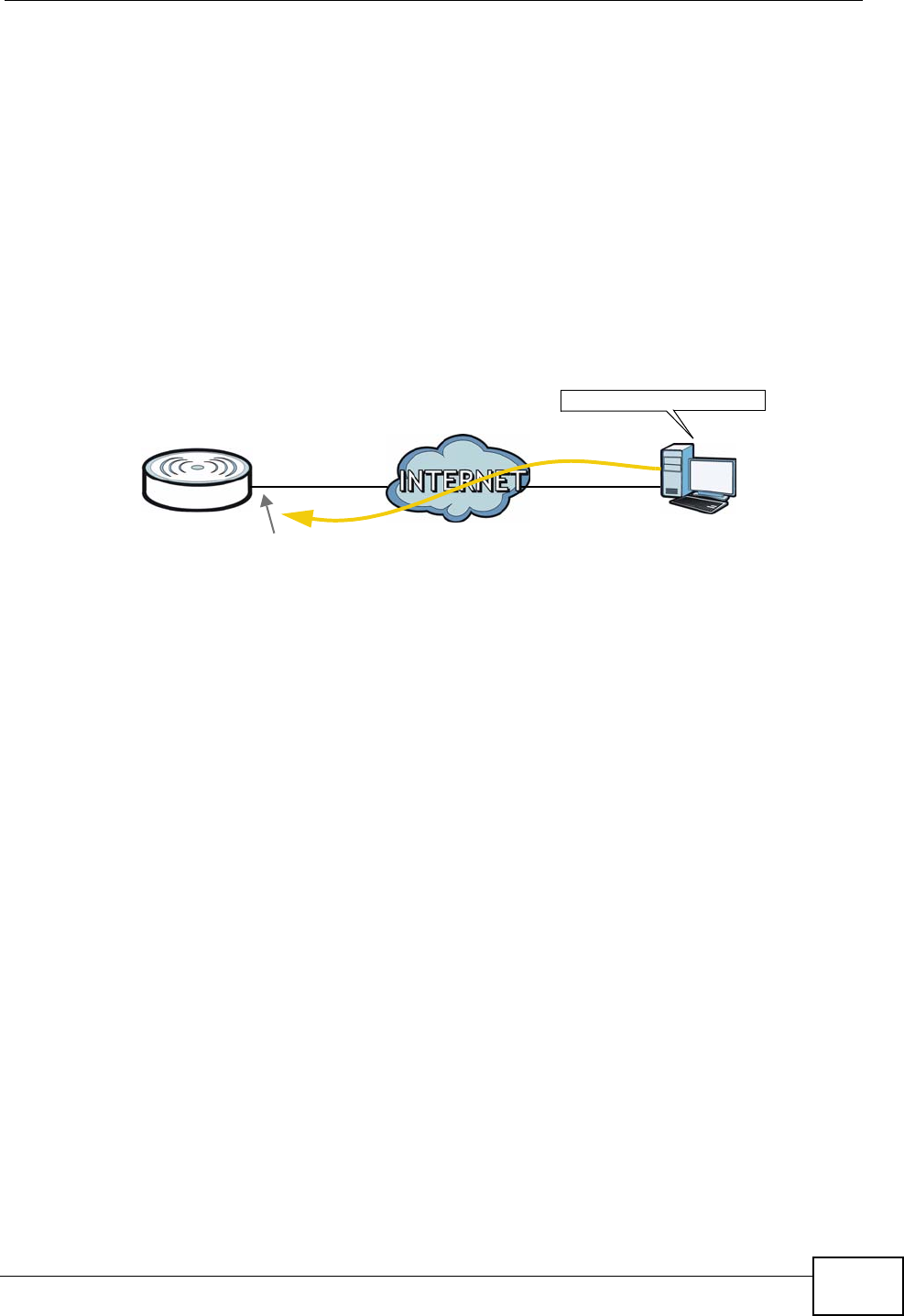
2.5.3 Testing the DDNS Setting
Now you should be able to access the NVG2053 from the Internet. To test this:
1Open a web browser on the computer (using the IP address a.b.c.d) that is
connected to the Internet.
2Type “http://zyxelrouter.dyndns.org” and press [Enter].
Chapter 2 Tutorials
NVG2053 User’s Guide 41
3The NVG2053’s login page should appear. You can then log into the NVG2053 and
manage it.
2.6 How to Route Traffic to Another Network
Using Static Route
In order to extend your Intranet and control traffic flow directions, you may
connect a router (R) to the NVG2053’s LAN. The router may be used to separate
two department networks. This tutorial shows how to configure a static routing
rule for two network routings.
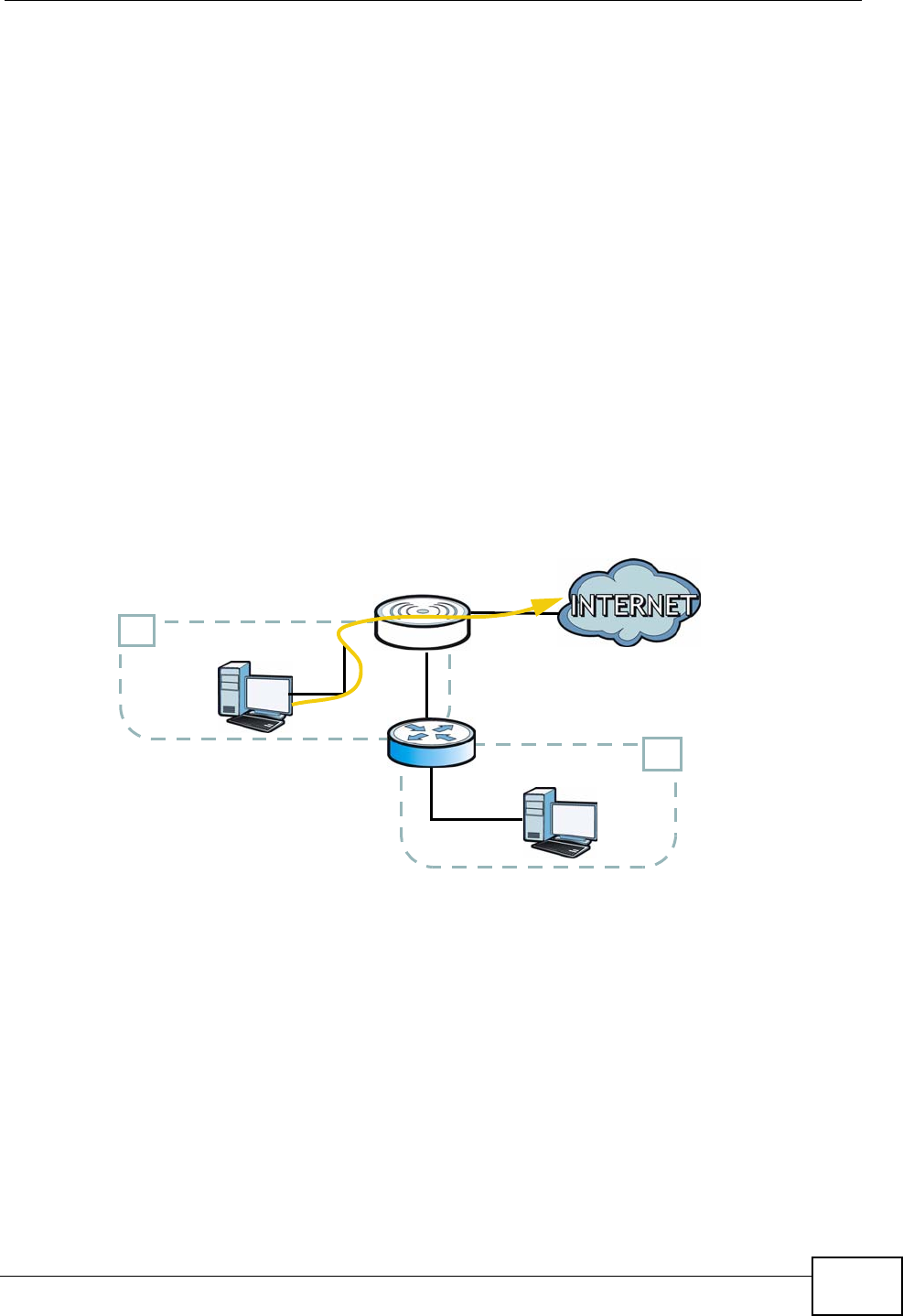
In the following figure, router R is connected to the NVG2053’s LAN. R connects to
two networks, N1 (192.168.1.x/24) and N2 (192.168.10.x/24). If you want to
send traffic from computer A (in N1 network) to computer B (in N2 network), the
traffic is sent to the NVG2053’s WAN default gateway by default. In this case, B
will never receive the traffic.
N2
B
N1
A
R
Chapter 2 Tutorials
NVG2053 User’s Guide
42
You need to specify a static routing rule on the NVG2053 to specify R as the router
in charge of forwarding traffic to N2. In this case, the NVG2053 routes traffic from
A to R and then R routes the traffic to B.
This tutorial uses the following example IP settings:
To configure a static route to route traffic from N1 to N2:
1Log into the NVG2053’s Web Configurator.
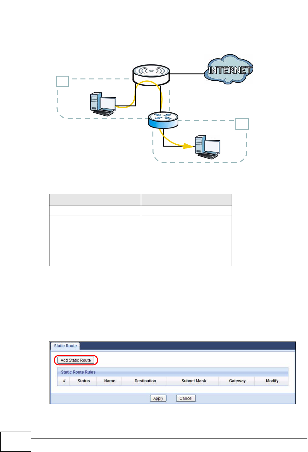
2Click Configuration > Network > Static Route.
3Click the Add Static Route button to create a new rule.
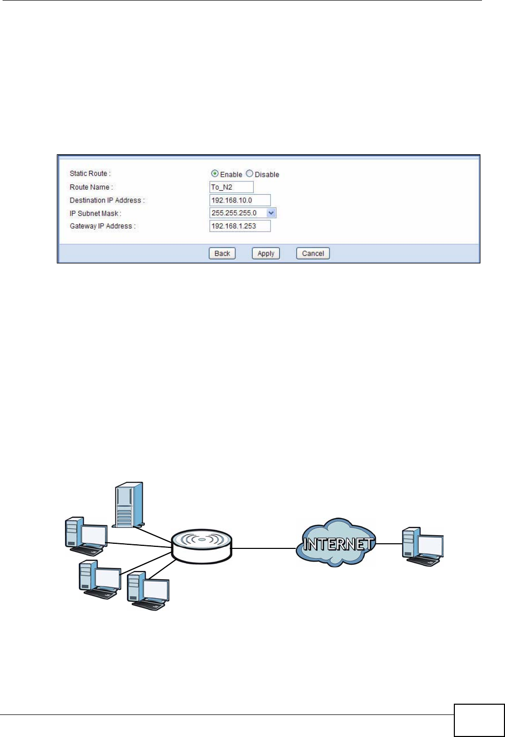
4Configure the Static Route > Edit screen using the following settings:
Table 2 IP Settings in this Tutorial
DEVICE / COMPUTER IP ADDRESS
The NVG2053’s WAN 172.16.1.1
The NVG2053’s LAN 192.168.1.1
A192.168.1.34
R’s N1 192.168.1.253
R’s N2 192.168.10.2
B192.168.10.33
N2
B
N1
A
R
Chapter 2 Tutorials
NVG2053 User’s Guide 43
4a Select Enable.
4b Specify a descriptive name for this routing rule.
4c Type “192.168.10.0” and select subnet mask “255.255.255.0” for the
destination, N2.
4d Type “192.168.1.253” (R’s N1 address) in the Gateway IP Address field.
4a Click Apply.
Now B should be able to receive traffic from A. You may need to additionally
configure B’s firewall settings to allow specific traffic to pass through.
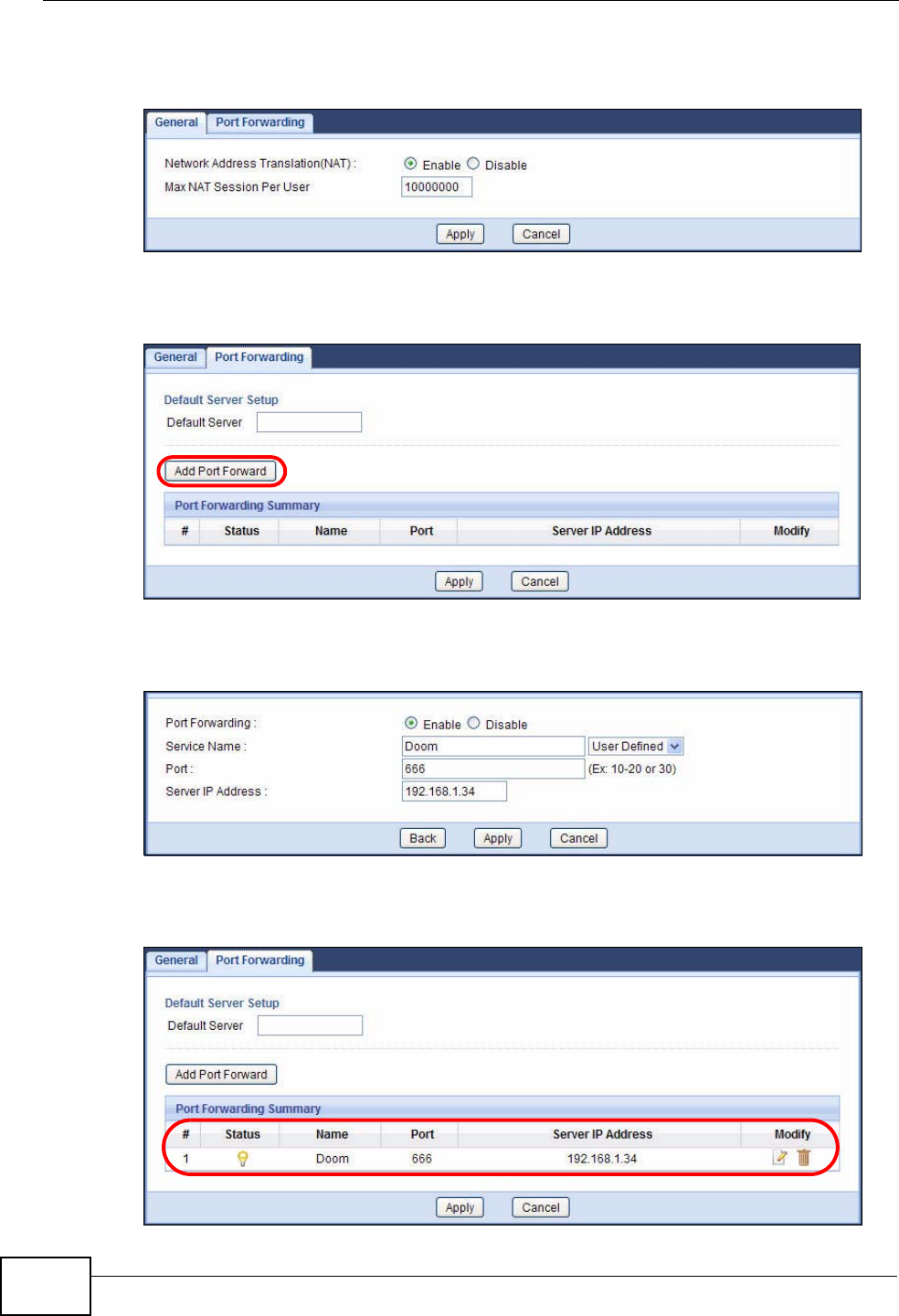
2.7 How to Set Up NAT Port Forwarding
You manage the Doom server on a computer behind the NVG2053. In order for
players on the Internet to communicate with the Doom server, you need to
configure the port settings and IP address on the NVG2053. Traffic should be
forwarded to the port 666 of the Doom server computer which has an IP address
of 192.168.1.34.
D=192.168.1.34 WAN
LAN
666
Chapter 2 Tutorials
NVG2053 User’s Guide
44
1Click Configuration > Network > NAT to open the General screen. Make sure
it is selected to enable NAT on the NVG2053 and click Apply.
2Click the Port Forwarding tab to open the following screen. Click the Add Port
Forward button to create a new rule.
3Configure the screen as follows to forward port 666 traffic to the computer with IP
address 192.168.1.34. Click Apply.
4The port forwarding settings you configured are listed in the Port Forwarding
screen.
Chapter 2 Tutorials
NVG2053 User’s Guide 45
Players on the Internet then can have access to the Doom server.
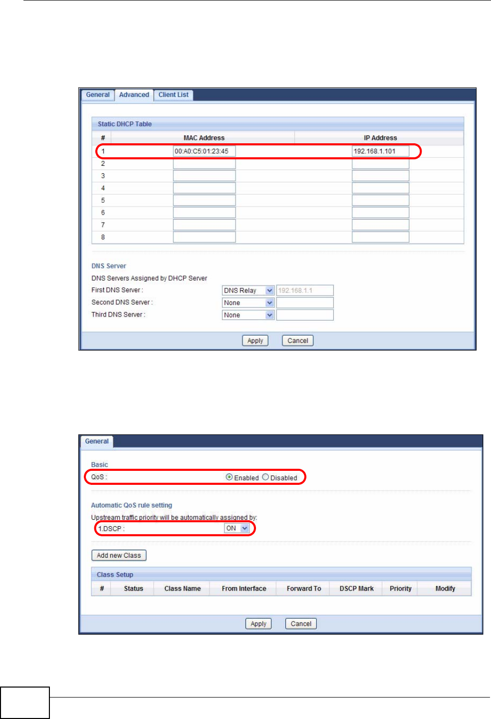
2.8 How to Use QoS to Prioritize LAN Traffic
In this example, your Internet connection has an upstream transmission speed of
50 Mbps. You want to configure a QoS class to assign the high priority queue (6)
to VoIP traffic from the phone port(s), so that voice traffic will not get delayed
when there is network congestion. Traffic from the boss’s IP address
(192.168.1.101 for example) is mapped to queue 5. Traffic that does not match
these two classes are assigned priority queue based on the DSCP value in the
packets.
50 Mbps
VoIP: Queue 6
Boss: Queue 5
IP = 192.168.1.101
Chapter 2 Tutorials
NVG2053 User’s Guide
46
1Click Configuration > DHCP Server > Advanced. Enter the MAC address of the
boss’s computer (“00:A0:C5:01:23:45” for example) in the MAC Address field
and 192.168.1.101 in the IP Address field to have the NVG2053 always assign
the IP address 192.168.1.101 to the boss’s computer. Click Apply.
2Click Network > QoS and select the Enabled option to turn on QoS on the
NVG2053.
Set DSCP to ON to have the NVG2053 assign priority to unmatched traffic based
on the DSCP value in the packets. Click Apply.
Chapter 2 Tutorials
NVG2053 User’s Guide 47
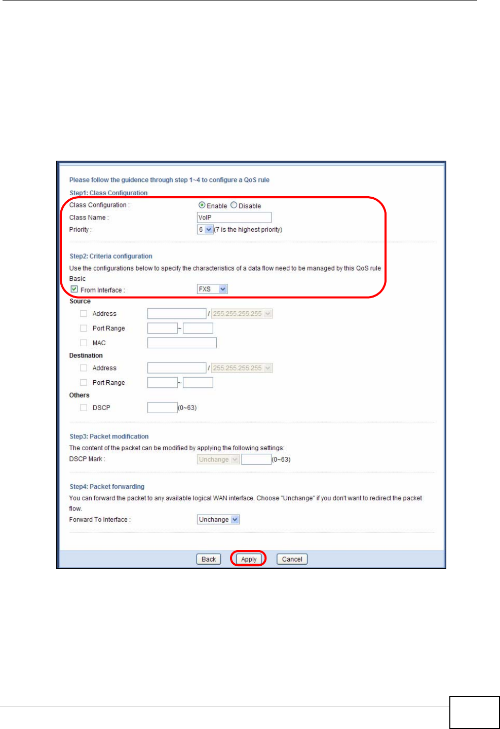
3Click Add new Class in the QoS > General scren to create a QoS class for VoIP
traffic.
4Give the class a name (“VoIP” for example).
Set Priority to 6.
Select From Interface and then FXS from the drop-down list to group traffic
coming from the phone port(s) on the NVG2053.
Leave all other fields as the default and click Apply.
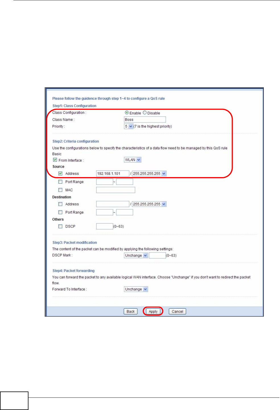
5Click Add new Class in the QoS > General scren to create a QoS class for traffic
from the boss’s IP address (10.1.1.23 in this example).
Chapter 2 Tutorials
NVG2053 User’s Guide
48
6Give the class a name (“Boss” for example).
Set Priority to 5.
Select From Interface and the interface to which the boss’s computer is
connected (WLAN in this example as he or she has a wireless connection to the
NVG2053).
Select Source Address and then enter the boss’s IP address in the field provided.
Leave all other fields as the default and click Apply.
VoIP traffic now should have higher priority and get through faster than the boss’s
traffic.

NVG2053 User’s Guide 49
CHAPTER 3
Connection Wizard
3.1 Overview
This chapter provides information on the wizard setup screens in the Web
Configurator.
The Web Configurator’s wizard setup helps you configure your device to access the
Internet. Refer to your ISP for your Internet account information. Leave a field
blank if you don’t have that information.
3.2 Accessing the Wizard
Launch your web browser and type "http://192.168.1.1" as the website address.
Note: The Wizard appears when the NVG2053 is accessed for the first time or when
you reset the NVG2053 to its default factory settings.
The Wizard screen opens. Choose your Language and click Connect to
Internet.
Figure 5 Welcome
Chapter 3 Connection Wizard
NVG2053 User’s Guide
50
Note: If you have already configured the wizard screens and want to open it again,
click the eaZy123 icon on the upper right corner of any Web Configurator
screen.
3.3 Connect to Internet
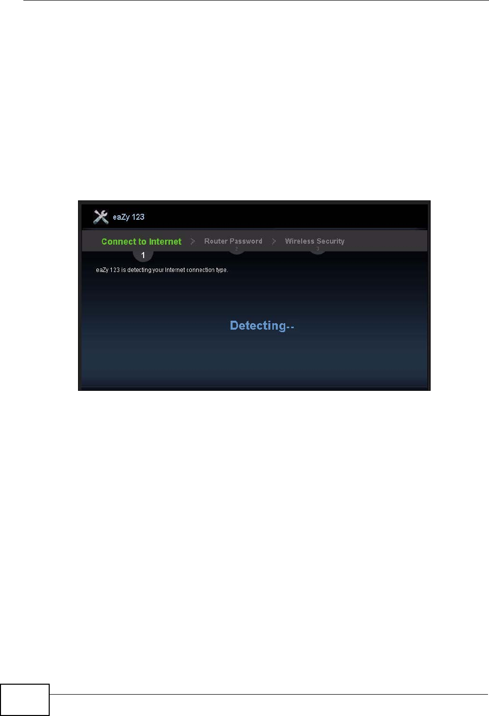
The NVG2053 offers three Internet connection types. They are Static IP, DHCP,
and PPPoE. The wizard attempts to detect which WAN connection type you are
using.
Figure 6 Detecting your Internet Connection Type
If the wizard does not detect a connection type, you must select one from the
drop-down list box. Check with your ISP to make sure you use the correct type.
Note: If you get an error message, check your hardware connections. Make sure your
Internet connection is up and running.
Chapter 3 Connection Wizard
NVG2053 User’s Guide 51
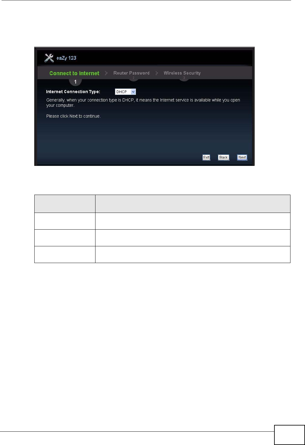
The following screen depends on your Internet connection type. Enter the details
provided by your Internet Service Provider (ISP) in the fields (if any).
Figure 7 Internet Connection Type
Your NVG2053 detects the following Internet Connection type.
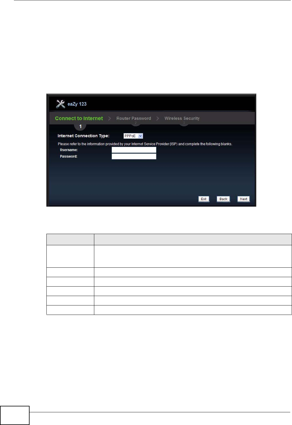
3.3.1 Connection Type: PPPoE
Point-to-Point Protocol over Ethernet (PPPoE) functions as a dial-up connection.
PPPoE is an IETF (Internet Engineering Task Force) standard specifying how a host
personal computer interacts with a broadband modem (for example DSL, cable,
wireless, etc.) to achieve access to high-speed data networks.
For the service provider, PPPoE offers an access and authentication method that
works with existing access control systems (for instance, RADIUS).
One of the benefits of PPPoE is the ability to let end users access one of multiple
network services, a function known as dynamic service selection. This enables the
service provider to easily create and offer new IP services for specific users.
Table 3 Internet Connection Type
CONNECTION
TYPE DESCRIPTION
PPPoE Select the PPPoE (Point-to-Point Protocol over Ethernet) option for
a dial-up connection.
DHCP Select the DHCP (Dynamic Host Configuration Protocol) option
when the WAN port is used as a regular Ethernet.
Static IP Select the Static IP if an administrator assigns the IP address of
your computer.
Chapter 3 Connection Wizard
NVG2053 User’s Guide
52
Operationally, PPPoE saves significant effort for both the subscriber and the ISP/
carrier, as it requires no specific configuration of the broadband modem at the
subscriber's site.
By implementing PPPoE directly on the NVG2053 (rather than individual
computers), the computers on the LAN do not need PPPoE software installed,
since the NVG2053 does that part of the task. Furthermore, with NAT, all of the
LAN's computers will have Internet access.
Figure 8 Internet Connection Type: PPPoE
The following table describes the labels in this screen.
Table 4 Internet Connection Type: PPPoE
LABEL DESCRIPTION
Internet
Connection
Type
Select the PPPoE option for a dial-up connection.
Username Type the user name given to you by your ISP.
Password Type the password associated with the user name above.
Exit Click this to close the wizard screen without saving.
Back Click this to return to the previous screen.
Next Click this to continue.
Chapter 3 Connection Wizard
NVG2053 User’s Guide 53
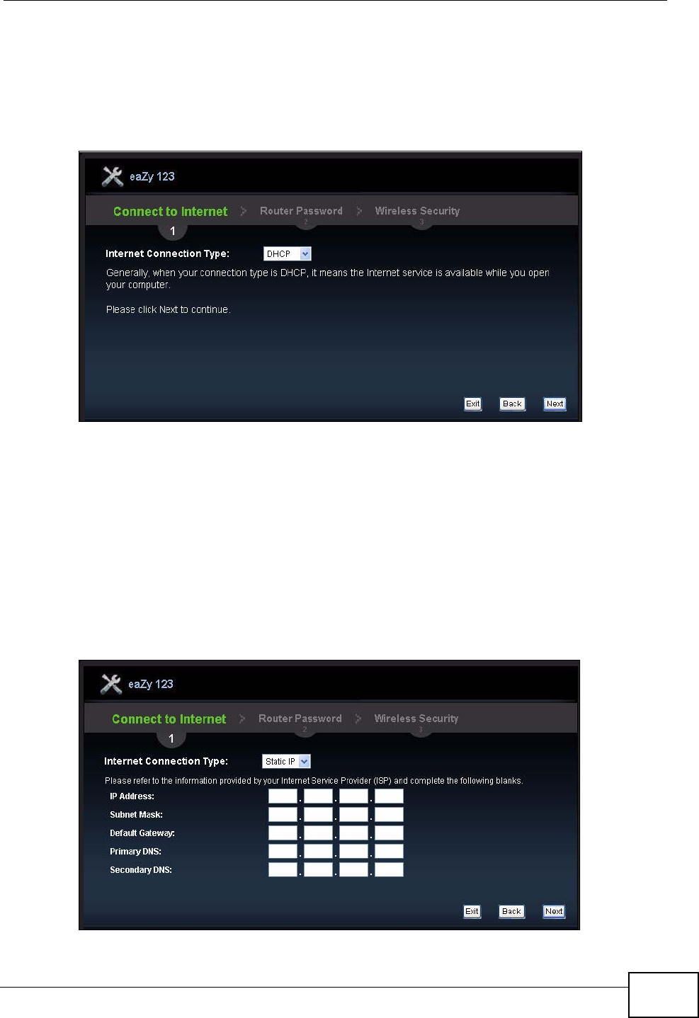
3.3.2 Connection Type: DHCP
Choose DHCP as the Internet Connection Type when the WAN port is used as a
regular Ethernet. Click Next.
Figure 9 Internet Connection Type: DHCP
Note: If you get an error screen after clicking Next, you might have selected the
wrong Internet connection type. Click Back, make sure your Internet
connection is working and select the right connection type. Contact your ISP if
you are not sure of your Internet connection type.
3.3.3 Connection Type: Static IP
Choose Static IP as the Internet Connection Type if your ISP assigned an IP
address for your Internet connection. Click Next.
Figure 10 Internet Connection Type: Static IP
Chapter 3 Connection Wizard
NVG2053 User’s Guide
54
The following table describes the labels in this screen.
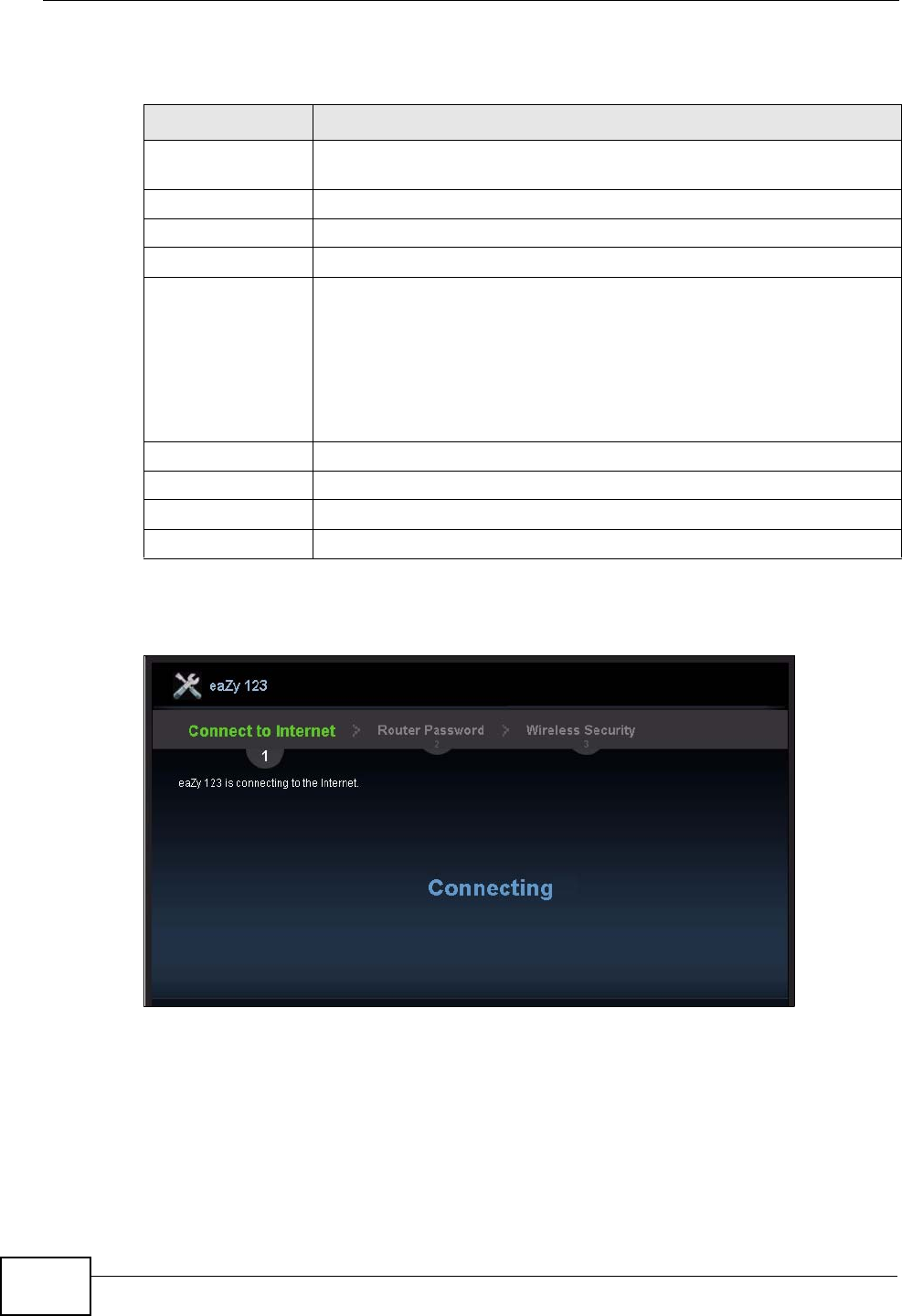
The NVG2053 connects to the Internet.
Figure 11 Connecting to the Internet
Note: If the Wizard successfully connects to the Internet, it proceeds to the next step.
If you get an error message, go back to the previous screen and make sure you
have entered the correct information provided by your ISP.
Table 5 Internet Connection Type: Static IP
LABEL DESCRIPTION
Internet
Connection Type Select the Static IP option.
IP Address Enter the IP address provided by your ISP.
Subnet Mask Enter the IP subnet mask in this field.
Default Gateway Enter the gateway IP address in this field.
Primary DNS DNS (Domain Name System) is for mapping a domain name to its
corresponding IP address and vice versa. The DNS server is
extremely important because without it, you must know the IP
address of a computer before you can access it. The NVG2053 uses a
system DNS server (in the order you specify here) to resolve domain
names for DDNS and the time server.
Enter the primary DNS server's IP address in the fields provided.
Secondary DNS Enter the secondary DNS server's IP address in the fields provided.
Exit Click this to close the wizard screen without saving.
Back Click this to return to the previous screen.
Next Click this to continue.
Chapter 3 Connection Wizard
NVG2053 User’s Guide 55
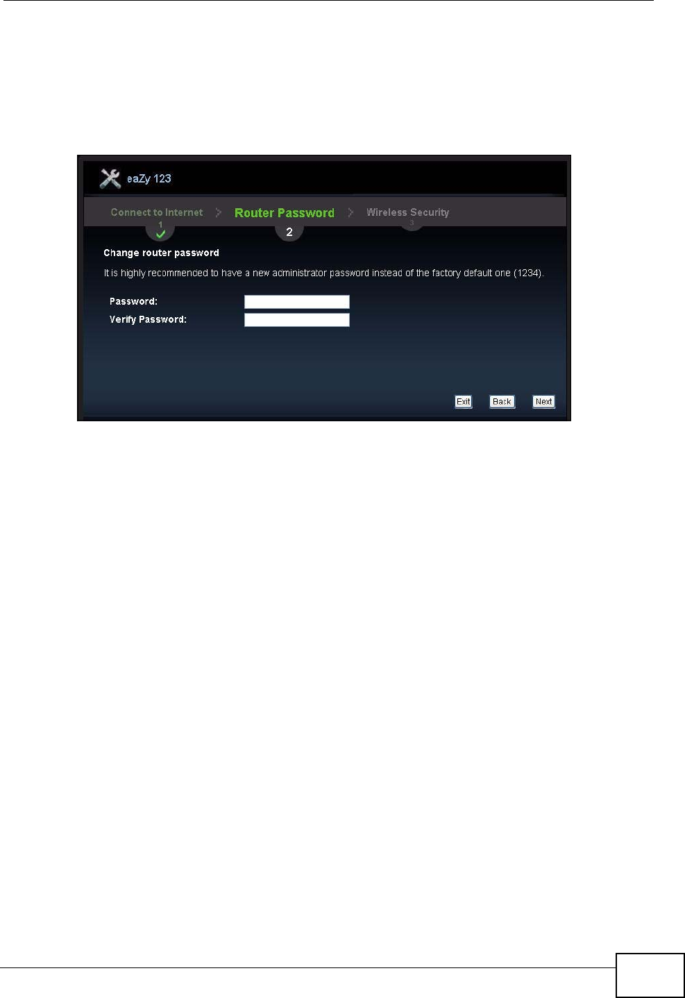
3.4 Router Password
Change the login password in the following screen. Enter the new password and
retype it to confirm. Click Next to proceed with the Wireless Security screen.
Figure 12 Router Password
3.5 Wireless Security
Configure Wireless Settings. Configure the wireless network settings on your
NVG2053 in the following screen. The fields that show up depend on the kind of
security you select.
Chapter 3 Connection Wizard
NVG2053 User’s Guide
56
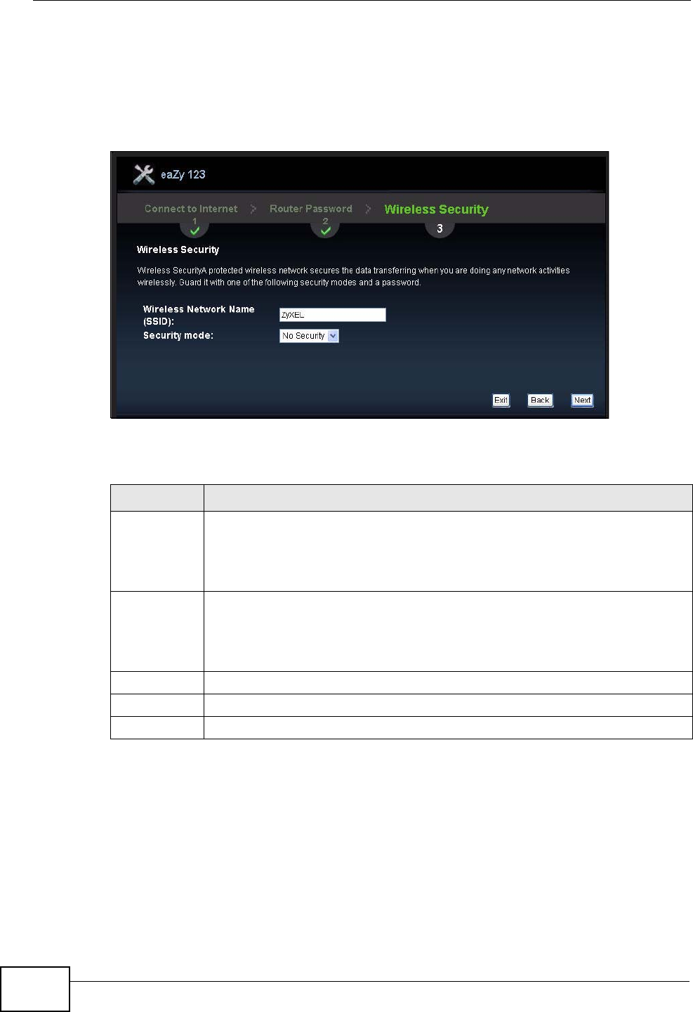
3.5.1 Wireless Security: No Security
Choose No Security in the Wireless Security screen to let wireless devices
within range access your wireless network.
Figure 13 Wireless Security: No Security
The following table describes the labels in this screen.
Table 6 Wireless Security: No Security
LABEL DESCRIPTION
Wireless
Network
Name
(SSID)
Enter a descriptive name (up to 32 printable 7-bit ASCII characters) for the
wireless LAN.
If you change this field on the NVG2053, make sure all wireless stations
use the same SSID in order to access the network.
Security
mode Select a security level from the drop-down list box.
Choose None to have no wireless LAN security configured. If you do not
enable any wireless security on your NVG2053, your network is accessible
to any wireless networking device that is within range.
Exit Click this to close the wizard screen without saving.
Back Click this to return to the previous screen.
Next Click this to continue.
Chapter 3 Connection Wizard
NVG2053 User’s Guide 57
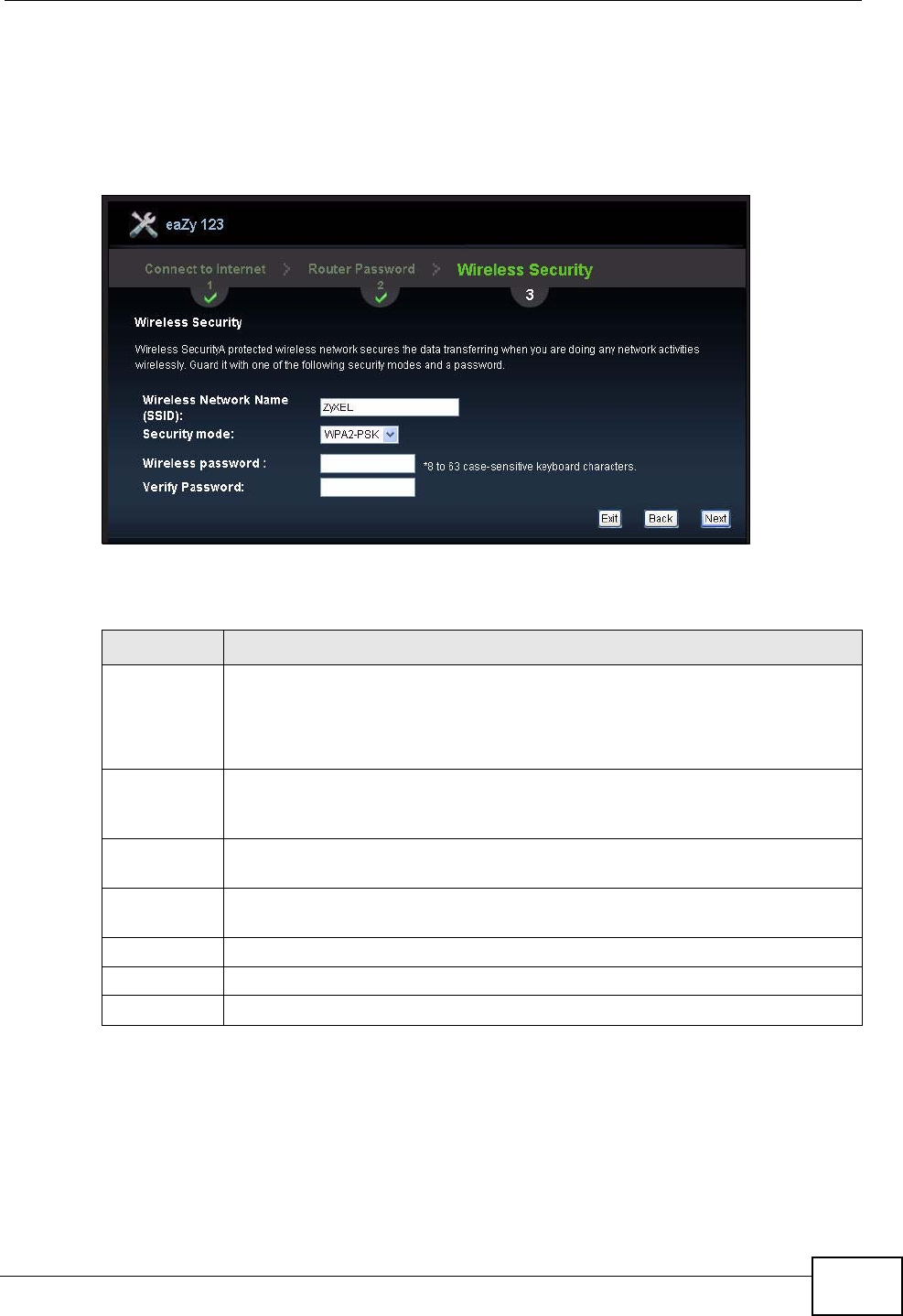
3.5.2 Wireless Security: WPA-PSK/WPA2-PSK
Choose WPA-PSK or WPA2-PSK security in the Wireless Security screen to set
up a password for your wireless network.
Figure 14 Wireless Security: WPA-PSK/WPA2-PSK
The following table describes the labels in this screen.
Congratulations! Open a web browser, such as Internet Explorer, to visit your
favorite website.
Table 7 Wireless Security: WPA-PSK/WPA2-PSK
LABEL DESCRIPTION
Wireless
Network
Name
(SSID)
Enter a descriptive name (up to 32 printable 7-bit ASCII characters) for the
wireless LAN.
If you change this field on the NVG2053, make sure all wireless stations
use the same SSID in order to access the network.
Security
mode Choose WPA-PSK or WPA2-PSK security to configure a Pre-Shared Key.
Choose this option only if your wireless clients support WPA-PSK or WPA2-
PSK respectively.
Wireless
password Type from 8 to 63 case-sensitive ASCII characters. You can set up the most
secure wireless connection by configuring WPA in the wireless LAN screens.
Verify
Password Retype the password to confirm.
Exit Click this to close the wizard screen without saving.
Back Click this to return to the previous screen.
Next Click this to continue.
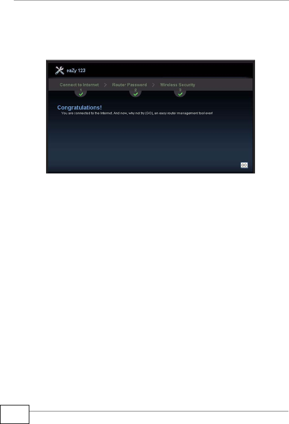
Chapter 3 Connection Wizard
NVG2053 User’s Guide
58
Note: If you cannot access the Internet when your computer is connected to one of
the NVG2053’s LAN ports, check your connections. Then turn the NVG2053
off, wait for a few seconds then turn it back on. If that does not work, log in to
the web configurator again and check you have typed all information correctly.
Figure 15 Congratulations
You have successfully set up your NVG2053 to operate on your network and
access the Internet. You are now ready to connect wirelessly to your NVG2053
and access the Internet.
You can click GO to open the login screen to acess the Web Configurator of your
NVG2053 for advanced settings.

NVG2053 User’s Guide 59
CHAPTER 4
Introducing the Web
Configurator
4.1 Overview
This chapter describes how to access the NVG2053 Web Configurator and provides
an overview of its screens.
The Web Configurator is an HTML-based management interface that allows easy
setup and management of the NVG2053 via Internet browser. Use Internet
Explorer 6.0 and later versions or Mozilla Firefox 3 and later versions. The
recommended screen resolution is 1024 by 768 pixels.
In order to use the Web Configurator you need to allow:
• Web browser pop-up windows from your device. Web pop-up blocking is enabled
by default in Windows XP SP (Service Pack) 2.
• JavaScript (enabled by default).
• Java permissions (enabled by default).
Refer to Appendix A on page 235 to see how to make sure these functions are
allowed in Internet Explorer.
4.2 Accessing the Web Configurator
1Make sure your NVG2053 hardware is properly connected and prepare your
computer or computer network to connect to the NVG2053 (refer to the Quick
Start Guide).
2Launch your web browser.
3Type "http://192.168.1.1" as the website address.
Your computer must be in the same subnet in order to access this website
address.
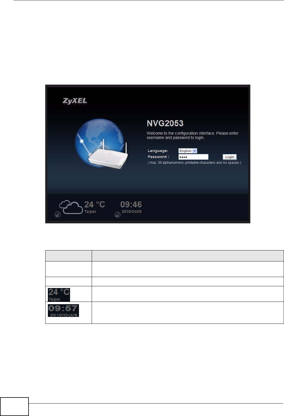
Chapter 4 Introducing the Web Configurator
NVG2053 User’s Guide
60
4.2.1 Login Screen
Note: If this is the first time you are accessing the Web Configurator, you may be
redirected to the Wizard. Refer to Chapter 3 on page 49 for the Connection
Wizard screens.
The Web Configurator initially displays the following login screen.
Figure 16 Login screen
The following table describes the labels in this screen.
4.2.1.1 Weather Edit
You can change the temperature unit and select the location for which you want to
know the weather.
Table 8 Login screen
LABEL DESCRIPTION
Language Select the language you want to use to configure the Web Configurator.
Click Login.
Password Type "1234" (default) as the password.
This shows the current weather, either in celsius or fahrenheit, of the
city you specify in Section 4.2.1.1 on page 60.
This shows the time (hh:mm) and date (yyyy/mm/dd) of the timezone
you select in Section 4.2.1.2 on page 61 or Section 22.2 on page 212.
The time is in 24-hour format, for example 15:00 is 3:00 PM.
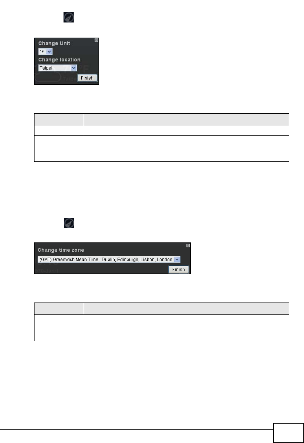
Chapter 4 Introducing the Web Configurator
NVG2053 User’s Guide 61
Click the icon to change the Weather display.
Figure 17 Change Weather
The following table describes the labels in this screen.
4.2.1.2 Time/Date Edit
One timezone can cover more than one country. You can choose a particular
country in which the NVG2053 is located and have the NVG2053 display and use
the current time and date for its logs.
Click the icon to change the time and date display.
Figure 18 Change Time Zone Screen
The following table describes the labels in this screen.
Note: You can also edit the timezone in Section 22.2 on page 212.
Table 9 Change Weather
LABEL DESCRIPTION
Change Unit Choose which temperature unit you want the NVG2053 to display.
Change location Select the location for which you want to know the weather. If the city
you want is not listed, choose one that is closest to it.
Finish Click this to apply the settings and refresh the date and time display.
Table 10 Change Time Zone Screen
LABEL DESCRIPTION
Change time
zone Select the specific country whose current time and date you want the
NVG2053 to display.
Finish Click this to apply the settings and refresh the weather display.
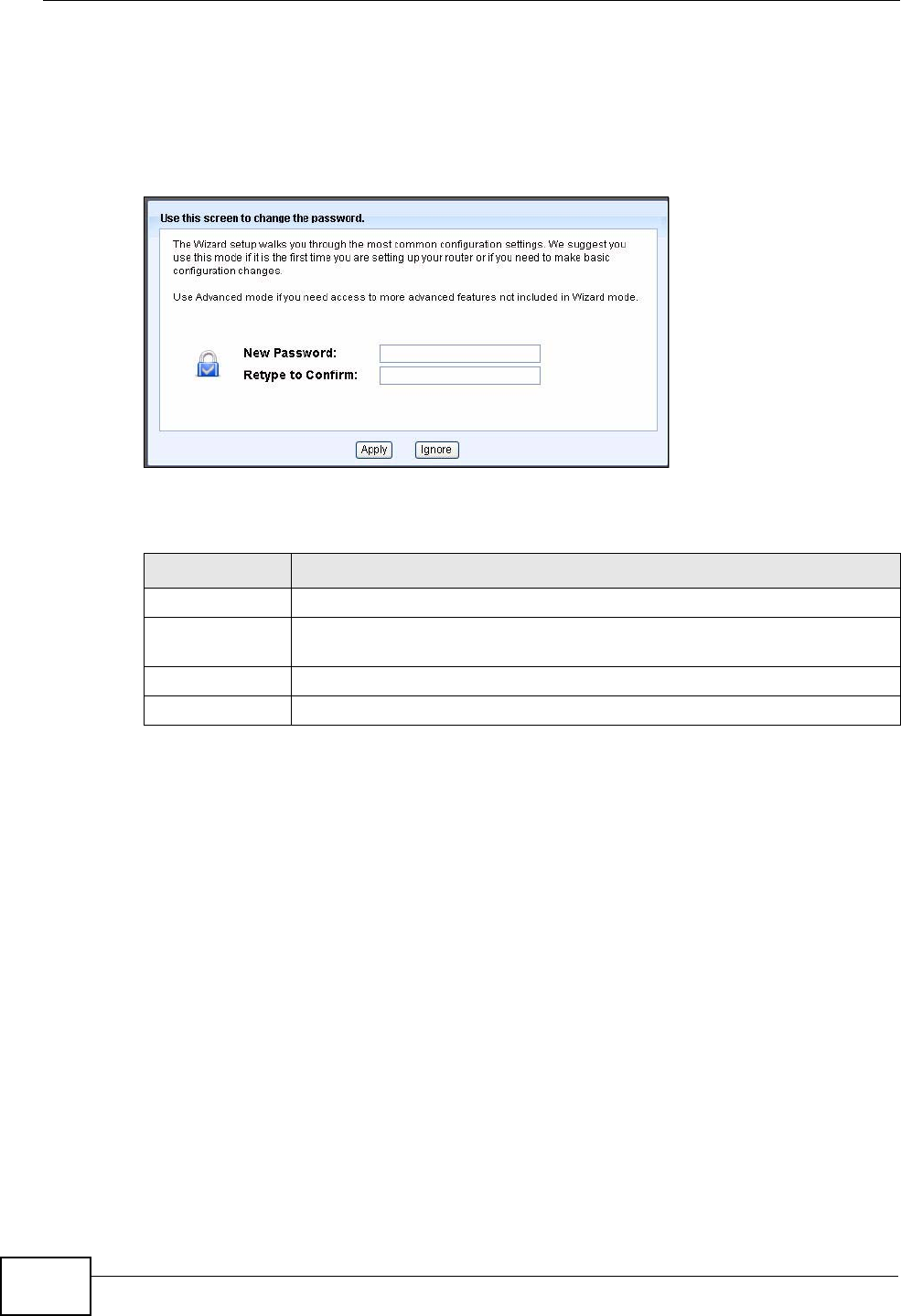
Chapter 4 Introducing the Web Configurator
NVG2053 User’s Guide
62
4.2.2 Password Screen
You should see a screen asking you to change your password (highly
recommended) as shown next.
Figure 19 Change Password Screen
The following table describes the labels in this screen.
Note: The management session automatically times out when the time period set in
the Administrator Inactivity Timer field expires (default five minutes; go to
Chapter 20 on page 207 to change this). Simply log back into the NVG2053 if
this happens.
Right after you log in, the Status screen is displayed. See Chapter 4 on page 81
for more information about the Status screen.
Table 11 Change Password Screen
LABEL DESCRIPTION
New Password Type a new password.
Retype to
Confirm Retype the password for confirmation.
Apply Click Apply to save your changes back to the NVG2053.
Ignore Click Ignore if you do not want to change the password this time.
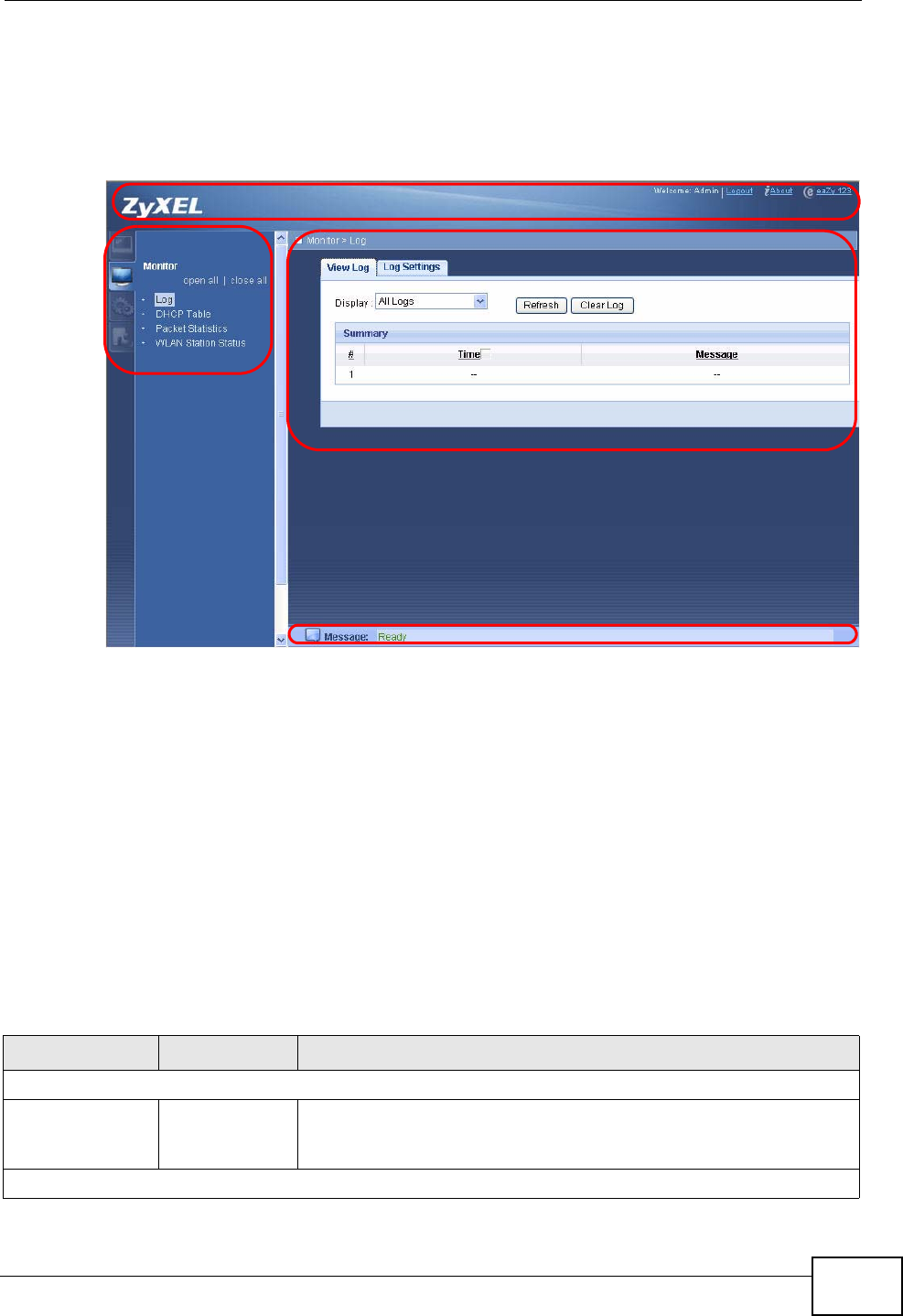
Chapter 4 Introducing the Web Configurator
NVG2053 User’s Guide 63
4.3 The Web Configurator Layout
Figure 20 The Web Configurator Layout
As illustrated above, the Web Configurator screen is divided into these parts:
•A - title bar
•B - navigation panel
•C - main window
•D - status bar
4.3.1 Navigation Panel
Use the menu items on the navigation panel to open screens to configure
NVG2053 features. The following tables describe each menu item.
A
BC
D
Table 12 Navigation Panel Summary
LINK TAB FUNCTION
Status
Status This screen shows the NVG2053’s general device and network
status information. Use this screen to access the statistics and
client list.
Monitor

Chapter 4 Introducing the Web Configurator
NVG2053 User’s Guide
64
Log View Log Use these screens to view the logs for the categories that you
selected and change your log settings.
Log Settings
DHCP Table Use this screen to view information related to your DHCP status.
Packet Statistics Use this screen to view port status, packet specific statistics, the
"system up time" and so on.
WLAN Station
Status Association
List Use this screen to view the wireless stations that are currently
associated to the NVG2053.
Configuration
Network
Broadband Use this screen to add or remove a WAN connection and configure
ISP parameters, WAN IP address assignment, and other advanced
properties
Wireless LAN General Use this screen to configure the wireless LAN settings and WLAN
authentication/security settings.
MAC Filter Use this screen to configure MAC filtering rules.
Advanced Use this screen to configure the advanced wireless LAN settings.
QoS WMM QoS allows you to prioritize wireless traffic according to the
delivery requirements of individual services.
WPS Use this screen to enable WPS (Wi-Fi Protected Setup) and view
the WPS status.
WPS Station Use this screen to use WPS to set up your wireless network.
Scheduling Use this screen to configure the times to enable or disable the
wireless LAN.
LAN IP Use this screen to configure NVG2053’s LAN IP address.
Advanced Use this screen to enable IP multicasting for your NVG2053 LAN
interface.
DHCP Server General Use this screen to enable the DHCP server for the LAN.
Advanced Use this screen to to always assign specific IP addresses to
individual MAC addresses (and host names).
Client List Use this screen to view current DHCP client information and to
always assign specific IP addresses to individual MAC addresses
(and host names).
QoS General Use this screen to enable QoS and define QoS classes.
NAT General Use this screen to enable NAT.
Port
Forwarding Use this screen to make your local servers visible to the outside
world.
Dynamic DNS This screen allows you to use a static hostname alias for a
dynamic IP address.
Static Route Use this screen to configure IP static routes to tell your device
about networks beyond the directly connected remote nodes.
UPnP Use this screen to turn UPnP on or off.
Security
Firewall General Use this screen to activate/deactivate the firewall.
Table 12 Navigation Panel Summary
LINK TAB FUNCTION
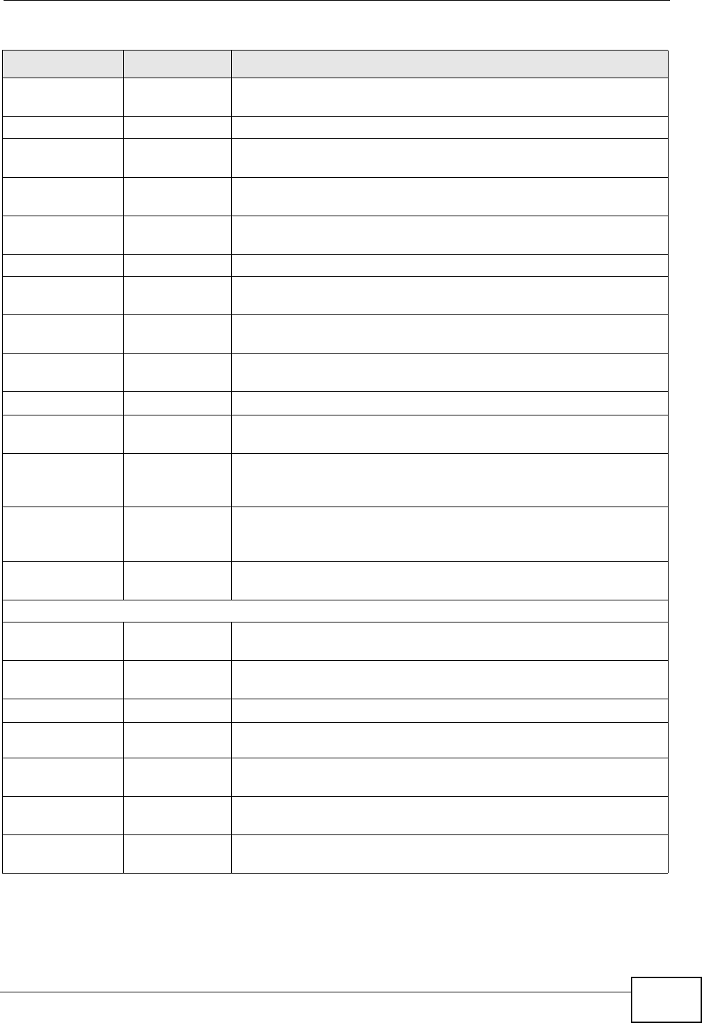
Chapter 4 Introducing the Web Configurator
NVG2053 User’s Guide 65
Services This screen shows a summary of the firewall rules, and allows you
to edit/add a firewall rule.
VoIP
SIP SIP Service
Provider Use this screen to configure the SIP server information, QoS for
VoIP calls and dialing interval and timer settings.
SIP Account Use this screen to congiure your SIP account information, dialing
plan rules and call features.
Phone Phone Device Use this screen to set which phone ports use which SIP accounts
and general phone port settings.
Region Use this screen to select your location and call service mode.
Call Rules Speed Dial Use this screen to configure speed dial for SIP phone numbers
that you call often.
PSTN call
through Use this screen to configure your NVG2053’s settings for regular
PSTN calls.
USB Services 3G Connection
Setup Use this screen to configure the 3G WAN connection.
Management
TR069 TR069
Configuration Use this screen to configure the NVG2053 to be managed by an
ACS (Auto Configuration Server).
Remote
MGMT WWW Use this screen to configure through which interface(s) and from
which IP address(es) users can use HTTP to manage the
NVG2053.
Telent Use this screen to configure through which interface(s) and from
which IP address(es) users can use Telnet to manage the
NVG2053.
ICMP Use this screen to set whether or not your device will respond to
pings.
Maintenance
General Use this screen to configure your device’s name, domain name,
and management inactivity timeout.
Password Password
Setup Use this screen to configure your device’s password.
Time Time Setting Use this screen to change your NVG2053’s time and date.
Firmware
Upgrade Use this screen to upload firmware to your device.
Backup/
Restore Use this screen to backup and restore your device’s configuration
(settings) or reset the factory default settings.
Language Use this screen to change the Web Configurator’s display
language.
Restart Use this screen to reboot the NVG2053 without turning the power
off.
Table 12 Navigation Panel Summary
LINK TAB FUNCTION

Chapter 4 Introducing the Web Configurator
NVG2053 User’s Guide
66
4.3.2 Main Window
The main window displays information and configuration fields. It is discussed in
the rest of this document.
4.3.3 Status Bar
Check the status bar when you click Apply or OK to verify that the configuration
has been updated.

67
PART II
Technical Reference

68

NVG2053 User’s Guide 69
CHAPTER 5
Status Screens
5.1 Overview
Use the Status screens to look at the current status of the device, system
resources and interfaces (LAN, WAN, WLAN and 3G). The Status screen also
provides statistics from traffic.
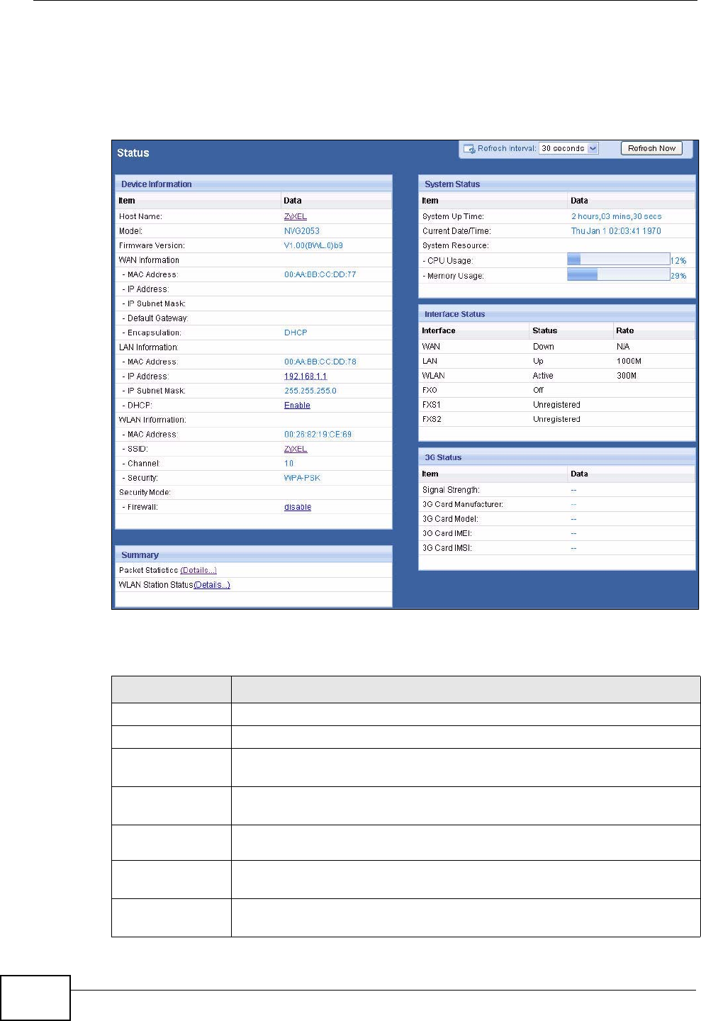
Chapter 5 Status Screens
NVG2053 User’s Guide
70
5.2 Status Screen
Click Status to open this screen.
Figure 21 Status Screen
Each field is described in the following table.
Table 13 Status Screen
LABEL DESCRIPTION
Refresh Interval Enter how often you want the NVG2053 to update this screen.
Refresh Now Click this to update this screen immediately.
Device
Information
Host Name This field displays the NVG2053 system name. It is used for
identification. Click this to go to the screen where you can change it.
Model
Number This is the model name of your device.
Firmware
Version This field displays the current version of the firmware inside the device.
It also shows the date the firmware version was created.
WAN
Information

Chapter 5 Status Screens
NVG2053 User’s Guide 71
MAC Address This is the MAC (Media Access Control) or Ethernet address unique to
your NVG2053. This MAC is used for the WAN connection and is
different from the LAN or WLAN MAC.
IP Address This field displays the current IPv4 address of the NVG2053 in the
WAN.
IP Subnet
Mask This field displays the current subnet mask in the WAN.
Default
Gateway This field displays the IP address of the default gateway, if applicable.
Encapsulatio
nThis field displays the method of encapsulation used by the WAN
connection.
LAN Information
MAC Address This is the MAC (Media Access Control) or Ethernet address unique to
your NVG2053. This MAC is used for LAN connections and differs from
the WLAN or WAN MAC.
IP Address This field displays the current IPv4 address of the NVG2053 in the LAN.
Click this to go to the screen where you can change it.
IP Subnet
Mask This field displays the current subnet mask in the LAN.
DHCP This field displays whether the NVG2053 acts as a DHCP server and
assigns IP addresses to other computers in the LAN (Enable) or not
(Disable).
Click this to go to the screen where you can change it.
WLAN
Information
MAC Address This is the MAC (Media Access Control) or Ethernet address unique to
your NVG2053. This MAC is used for WLAN connections and differs
from the LAN or WAN MAC.
SSID This is the descriptive name used to identify the NVG2053 in this
wireless network. Click this to go to the screen where you can change
it.
Channel This is the channel number used by the NVG2053 now.
Security This shows the level of wireless security the NVG2053 is using in this
wireless network.
Security Mode
Firewall This displays whether or not the NVG2053’s firewall is activated. Click
this to go to the screen where you can change it.
Summary
Packet
Statistics Click this link to view packet specific statistics of the WAN
connection(s). See Section 6.5 on page 77.
WLAN Station
Status Click this link to display the MAC address(es) of the wireless stations
that are currently associating with the NVG2053. See Section 6.6 on
page 79.
System Status
Table 13 Status Screen
LABEL DESCRIPTION
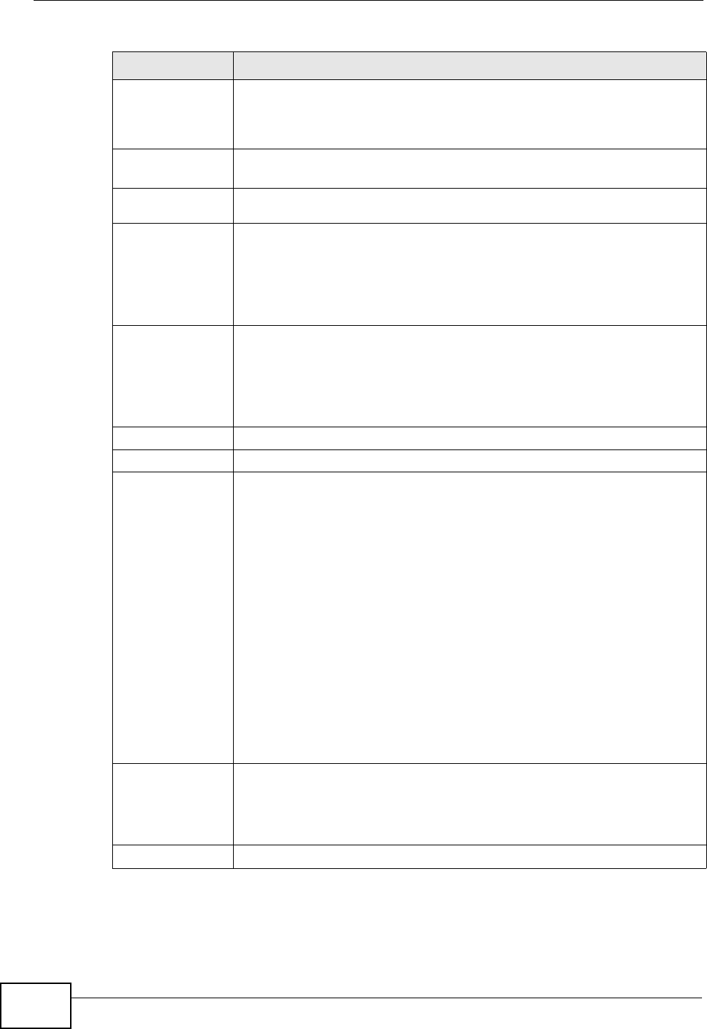
Chapter 5 Status Screens
NVG2053 User’s Guide
72
System
Uptime This field displays how long the NVG2053 has been running since it last
started up. The NVG2053 starts up when you plug it in, when you
restart it, or when you reset it using the Maintenance > Backup/
Restore screen or the RESET button (see Section 1.6 on page 25).
Current
Date/Time This field displays the current date and time in the NVG2053. You can
change this in Maintenance > Time.
System
Resource
CPU Usage This field displays what percentage of the NVG2053’s processing ability
is currently used. When this percentage is close to 100%, the NVG2053
is running at full load, and the throughput is not going to improve
anymore. If you want some applications to have more throughput, you
should turn off other applications (for example, using QoS; see Chapter
11 on page 131).
Memory
Usage This field displays what percentage of the NVG2053’s memory is
currently used. Usually, this percentage should not increase much. If
memory usage does get close to 100%, the NVG2053 is probably
becoming unstable, and you should restart the device. See Section
26.3 on page 223, or turn off the device (unplug the power) for a few
seconds.
Interface Status
Interface This column displays each interface the NVG2053 has.
Status This field indicates whether or not the NVG2053 is using the interface.
For the LAN or Ethernet WAN interface, this field displays Up when the
NVG2053 is using the interface and Down when the line is
disconnected.
For the WLAN interface, it displays Active when WLAN is enabled or
Down when WLAN is not active.
For the FXO interface, it displays Off when the LINE port is
disconnected, and On when the LINE port is connected.
For the FXS interface, it displays:
•Registered when the PHONE port is connected and the SIP
account used by the phone attached to this PHONE port is active
and registered.
•Unegistered when the PHONE port is disconnected and/or the SIP
account used by the phone attached to this PHONE port is not
active or not registered.
Rate For the LAN or Ethernet WAN interface, this displays the port speed or
N/A when the interface is not connected.
For the WLAN interface, it displays the maximum transmission rate
when WLAN is enabled or N/A when WLAN is disabled.
3G Status
Table 13 Status Screen
LABEL DESCRIPTION

Chapter 5 Status Screens
NVG2053 User’s Guide 73
Signal
Strength This field displays the signal strength of the 3G network to which the
3G card on the NVG2053 is connecting.
The signal strength mainly depends on the antenna output power and
the distance between your NVG2053 and the service provider’s base
station.
3G Card
Manufacturer This field displays the manufacturer of your 3G card.
3G Card
Model This field displays the model name of your 3G card.
3G Card IMEI This field displays the International Mobile Equipment Number (IMEI)
which is the serial number of the 3G wireless card. IMEI is a unique 15-
digit number used to identify a mobile device.
3G Card IMSI This field displays the International Mobile Subscriber Identity (IMSI)
stored in the SIM (Subscriber Identity Module) card. The SIM card is
installed in a mobile device and used for authenticating a customer to
the carrier network. IMSI is a unique 15-digit number used to identify a
user on a network.
Table 13 Status Screen
LABEL DESCRIPTION

Chapter 5 Status Screens
NVG2053 User’s Guide
74

NVG2053 User’s Guide 75
CHAPTER 6
Monitor
6.1 Overview
This chapter discusses read-only information related to the device state of the
NVG2053.
Note: To access the Monitor screens, you can also click the links in the Summary
table of the Status screen to view packets sent/received on a WAN connection
as well as the status of wireless clients connected to the NVG2053.
6.1.1 What You Can Do in this Chapter
•Use the View Log screen (Section 6.2 on page 75) to see the logs for the
categories that you selected in the Log Settings screen.
•Use the Log Settings screen (Section 6.3 on page 76) to configure which logs
and/or immediate alerts the NVG2053 is to record.
•Use the DHCP Table screen (Section 6.4 on page 77) to view information
related to your DHCP status.
•use the Packet Statistics screen (Section 6.5 on page 77) to view port status,
packet specific statistics, the "system up time" and so on.
•Use the WLAN Station Status screen (Section 6.6 on page 79) to view the
wireless stations that are currently associated to the NVG2053.
6.2 The View Log Screen
Click Monitor > Log to open the View Log screen. Use the View Log screen to
see the logs for the categories that you selected in the Log Settings screen (see
Section 6.3 on page 76).
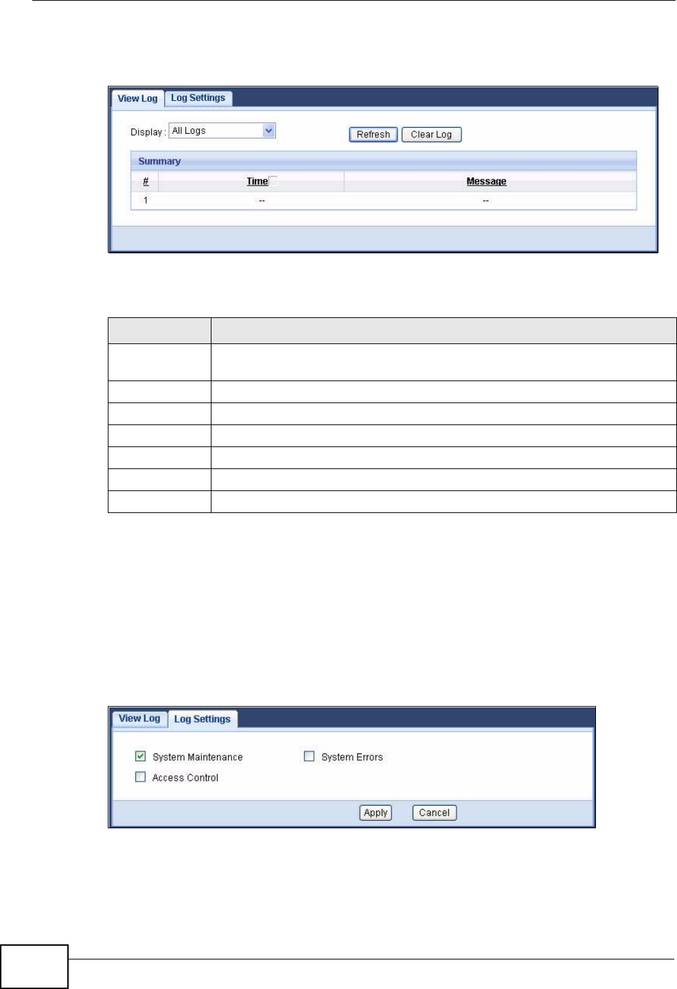
Chapter 6 Monitor
NVG2053 User’s Guide
76
The log wraps around and deletes the old entries after it fills.
Figure 22 Monitor > Log > View Log
The following table describes the fields in this screen.
6.3 The Log Settings Screen
Use the Log Settings screen to choose which categories of events and/or alerts
the NVG2053 is to log and then display the logs. To change your NVG2053’s log
settings, click Monitor > Log > Log Settings. The screen appears as shown.
Figure 23 Monitor > Log > Log Settings
Table 14 Monitor > Log > View Log
LABEL DESCRIPTION
Display Select a category of logs to view. Select All Logs to view logs from all of
the log categories that you selected in the Log Settings screen.
Refresh Click Refresh to renew the log screen.
Clear Log Click Clear Log to delete all the logs.
Summary The logs display in the table.
#This field is a sequential value and is not associated with a specific entry.
Time This field displays the time the log was recorded.
Message This field states the reason for the log.
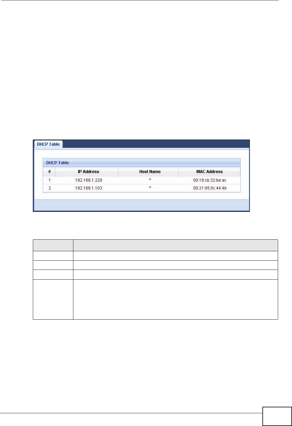
Chapter 6 Monitor
NVG2053 User’s Guide 77
6.4 The DHCP Table Scren
DHCP (Dynamic Host Configuration Protocol, RFC 2131 and RFC 2132) allows
individual clients to obtain TCP/IP configuration at start-up from a server. You can
configure the NVG2053 as a DHCP server or disable it. When configured as a
server, the NVG2053 provides the TCP/IP configuration for the clients. If DHCP
service is disabled, you must have another DHCP server on that network, or else
the computer must be manually configured.
Click Monitor > DHCP Table. Read-only information here relates to your DHCP
status. The DHCP table shows current DHCP client information (including IP
Address, Host Name and MAC Address) of all network clients using the
NVG2053’s DHCP server.
Figure 24 DHCP Table
The following table describes the labels in this screen.
6.5 The Packet Statistics Screen
Click Monitor > Packet Statistics or the Packet Statistics (Details...)
hyperlink in the Status screen. Read-only information here includes WAN port
Table 15 DHCP Table
LABEL DESCRIPTION
# This is the index number of the host computer.
IP Address This indicates the IP address assigned to this client computer.
Host Name This indicates the computer host name.
MAC Address This field shows the MAC address of the client computer.
Every Ethernet device has a unique MAC (Media Access Control) address
which uniquely identifies a device. The MAC address is assigned at the
factory and consists of six pairs of hexadecimal characters, for example,
00:A0:C5:00:00:02.
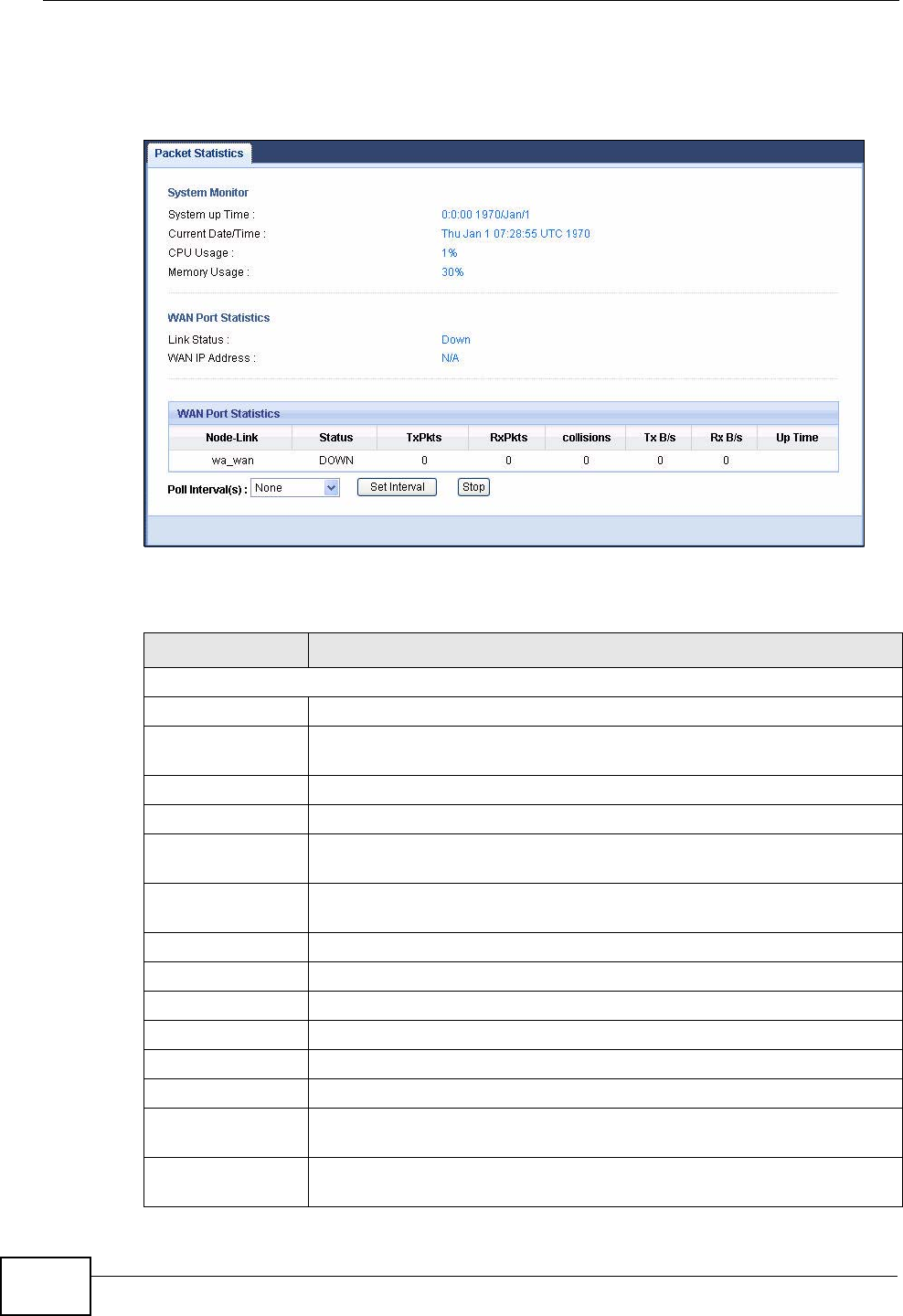
Chapter 6 Monitor
NVG2053 User’s Guide
78
status, packet specific statistics, system information and the "system up time".
The Poll Interval(s) field is configurable and is used for refreshing the screen.
Figure 25 Packet Statistics
The following table describes the labels in this screen.
Table 16 Packet Statistics
LABEL DESCRIPTION
System Monitor
System Up Time This is the total time the NVG2053 has been on.
Current Date/
Time This field displays your NVG2053’s present date and time.
CPU Usage This field specifies the percentage of CPU utilization.
Memory Usage This field specifies the percentage of memory utilization.
WAN Port
Statistics
Link Status This displays the port speed and duplex setting or Down when the
line is disconnected.
WAN IP Address This is the IP address of the NVG2053’s WAN port.
Node Link This field displays the descriptive name of the WAN connection.
Status This field shows whether the WAN connection is up or down.
TxPkts This is the number of transmitted packets on this connection.
RxPkts This is the number of received packets on this connection.
Collisions This is the number of collisions on this connection.
Tx B/s This displays the transmission speed in bytes per second on this
connection.
Rx B/s This displays the reception speed in bytes per second on this
connection.
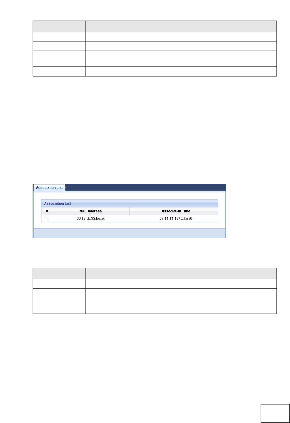
Chapter 6 Monitor
NVG2053 User’s Guide 79
6.6 The WLAN Station Status Screen
Click Monitor > WLAN Station Status or the WLAN Station Status
(Details...) hyperlink in the Status screen. View the wireless stations that are
currently associated to the NVG2053 in the Association List. Association means
that a wireless client (for example, your network or computer with a wireless
network card) has connected successfully to the AP (or wireless router) using the
same SSID, channel and security settings.
Figure 26 Summary: Wireless Association List
The following table describes the labels in this screen.
Up Time This is the total time the NVG2053 has been for each session.
Poll Interval(s) Enter the time interval in seconds for refreshing statistics in this field.
Set Interval Click this button to apply the new poll interval you entered in the Poll
Interval(s) field.
Stop Click Stop to stop refreshing statistics.
Table 16 Packet Statistics
LABEL DESCRIPTION
Table 17 Summary: Wireless Association List
LABEL DESCRIPTION
# This is the index number of an associated wireless station.
MAC Address This field displays the MAC address of an associated wireless station.
Association Time This field displays the time and date a wireless station first associated
with the NVG2053’s WLAN network.

Chapter 6 Monitor
NVG2053 User’s Guide
80
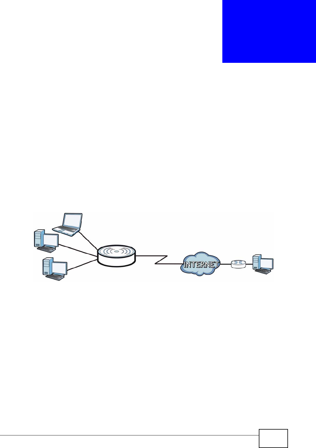
NVG2053 User’s Guide 81
CHAPTER 7
Broadband
7.1 Overview
This chapter discusses the NVG2053’s Broadband screens. Use these screens to
configure your NVG2053 for Internet access.
A WAN (Wide Area Network) connection is an outside connection to another
network or the Internet. It connects your private networks such as a LAN (Local
Area Network) and other networks, so that a computer in one location can
communicate with computers in other locations.
Figure 27 LAN and WAN
See Section 7.4 on page 90 for advanced technical information on WAN.
7.1.1 What You Can Do in this Chapter
Use the Broadband screen (Section 7.3 on page 83) to view and configure the
WAN settings on the NVG2053 for Internet access.
7.2 What You Need To Know
The information in this section can help you configure the screens for your WAN
connection, as well as enable/disable some advanced features of your NVG2053.
WAN
LAN

Chapter 7 Broadband
NVG2053 User’s Guide
82
Encapsulation Method
Encapsulation is used to include data from an upper layer protocol into a lower
layer protocol. To set up a WAN connection to the Internet, you need to use the
same encapsulation method used by your ISP (Internet Service Provider). If your
ISP offers a dial-up Internet connection using PPPoE (PPP over Ethernet), they
should also provide a username and password (and service name) for user
authentication.
WAN IP Address
The WAN IP address is an IP address for the NVG2053, which makes it accessible
from an outside network. It is used by the NVG2053 to communicate with other
devices in other networks. It can be static (fixed) or dynamically assigned by the
ISP each time the NVG2053 tries to access the Internet.
If your ISP assigns you a static WAN IP address, they should also assign you the
subnet mask and DNS server IP address(es) and a gateway IP address.
DNS Server Address Assignment
Use Domain Name System (DNS) to map a domain name to its corresponding IP
address and vice versa, for instance, the IP address of www.zyxel.com is
204.217.0.2. The DNS server is extremely important because without it, you must
know the IP address of a computer before you can access it.
The NVG2053 can get the DNS server addresses in the following ways.
1The ISP tells you the DNS server addresses, usually in the form of an information
sheet, when you sign up. If your ISP gives you DNS server addresses, manually
enter them in the DNS server fields.
2If your ISP dynamically assigns the DNS server IP addresses (along with the
NVG2053’s WAN IP address), set the DNS server fields to get the DNS server
address from the ISP.
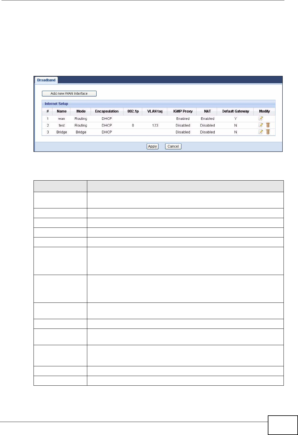
Chapter 7 Broadband
NVG2053 User’s Guide 83
7.3 The Broadband Screen
Use this screen to change your NVG2053’s Internet access settings. Click
Network > Broadband from the Configuration menu. The summary table
shows you the configured WAN services (connections) on the NVG2053.
Figure 28 Network > Broadband
The following table describes the labels in this screen.
Table 18 Network > Broadband
LABEL DESCRIPTION
Add new WAN
interface Click this button to create a new connection.
# This is the index number of the connection.
Name This is the service name of the connection.
Mode This shows whether the connection is in routing mode or bridge mode.
Encapsulation This shows the method of encapsulation used by this connection.
8021p This indicates the 802.1P priority level assigned to traffic sent through
this connection.
This field is blank when there is no priority level assigned.
VLAN tag This indicates the VLAN ID number assigned to traffic sent through
this connection.
This field is blank when there is no VLAN ID number assigned.
IGMP Proxy This shows whether the NVG2053 act as an IGMP proxy on this
connection.
NAT This shows whether NAT is activated or not for this connection.
Default Gateway This shows whether the NVG2053 use the WAN interface of this
connection as the system default gateway.
Modify Click the Edit icon to configure the WAN connection.
Click the Delete icon to remove the WAN connection.
Apply Click Apply to save your changes back to the NVG2053.
Cancel Click Cancel to return to the previous configuration.
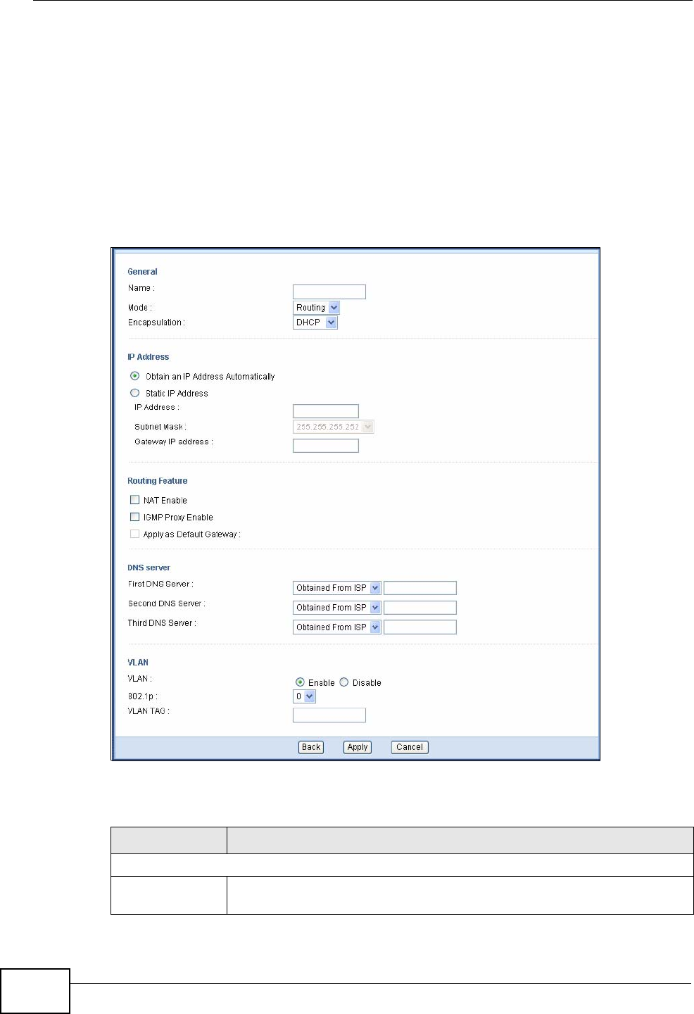
Chapter 7 Broadband
NVG2053 User’s Guide
84
7.3.1 Broadband Configuration
Click the Edit or Add button in the Broadband screen to configure a WAN
connection. The screen differs according to the mode and encapsulation you
choose.
7.3.1.1 DHCP
This screen displays when you select the Routing mode and DHCP encapsulation.
Figure 29 Network > Broadband: DHCP Encapsulation
The following table describes the labels in this screen.
Table 19 Network > Broadband: DHCP Encapsulation
LABEL DESCRIPTION
General
Name Specify a descriptive name of up to 15 alphanumeric characters for this
connection.

Chapter 7 Broadband
NVG2053 User’s Guide 85
Mode Select Routing (default) from the drop-down list box if your ISP give
you one IP address only and you want multiple computers to share an
Internet account.
Select Bridge when your ISP provides you more than one IP address
and you want the connected computers to get individual IP address
from ISP’s DHCP server directly. If you select Bridge, you cannot use
routing functions, such as QoS, Firewall, DHCP server and NAT on
traffic from the selected LAN port(s).
Encapsulation You must choose the DHCP (Ethernet) option when the WAN port is
used as a regular Ethernet.
IP Address
Obtain an IP
Address
Automatically
A static IP address is a fixed IP that your ISP gives you. A dynamic IP
address is not fixed; the ISP assigns you a different one each time you
connect to the Internet. Select this if you have a dynamic IP address.
Static IP
Address Select this option If the ISP assigned a fixed IP address.
IP Address Enter the static IP address provided by your ISP.
IP Subnet
Mask Enter the subnet mask provided by your ISP.
Gateway IP
Address Enter the gateway IP address provided by your ISP.
Routing Feature
NAT Enable Select this option to activate NAT on this connection.
IGMP Proxy
Enable Internet Group Multicast Protocol (IGMP) is a network-layer protocol
used to establish membership in a Multicast group - it is not used to
carry user data.
Select this option to have the NVG2053 act as an IGMP proxy on this
connection. This allows the NVG2053 to get subscribing information
and maintain a joined member list for each multicast group. It can
reduce multicast traffic significantly.
Apply as Default
Gateway Select this option to have the NVG2053 use the WAN interface of this
connection as the system default gateway.
This field is not configurable when another connection has been set to
be the deafult gateway through which the NVG2053 forwards the
traffic.
DNS Server
First DNS Server
Second DNS
Server
Third DNS
Server
Select Obtained From ISP if your ISP dynamically assigns DNS server
information (and the NVG2053's WAN IP address). The field to the right
displays the (read-only) DNS server IP address that the ISP assigns.
Select UserDefined if you have the IP address of a DNS server. Enter
the DNS server's IP address in the field to the right.
Select None if you do not want to configure DNS servers. If you do not
configure a DNS server, you must know the IP address of a computer in
order to access it.
VLAN
Table 19 Network > Broadband: DHCP Encapsulation
LABEL DESCRIPTION

Chapter 7 Broadband
NVG2053 User’s Guide
86
7.3.2 PPPoE Encapsulation
The NVG2053 supports PPPoE (Point-to-Point Protocol over Ethernet). PPPoE is an
IETF standard (RFC 2516) specifying how a personal computer (PC) interacts with
a broadband modem (DSL, cable, wireless, etc.) connection. The PPPoE option is
for a dial-up connection using PPPoE.
For the service provider, PPPoE offers an access and authentication method that
works with existing access control systems (for example Radius).
One of the benefits of PPPoE is the ability to let you access one of multiple network
services, a function known as dynamic service selection. This enables the service
provider to easily create and offer new IP services for individuals.
Operationally, PPPoE saves significant effort for both you and the ISP or carrier, as
it requires no specific configuration of the broadband modem at the customer site.
By implementing PPPoE directly on the NVG2053 (rather than individual
computers), the computers on the LAN do not need PPPoE software installed,
since the NVG2053 does that part of the task. Furthermore, with NAT, all of the
LANs’ computers will have access.
VLAN Select Enable to add the VLAN tag (specified below) to the outgoing
traffic through this connection. Otherwise, select Disable.
802.1p IEEE 802.1p defines up to 8 separate traffic types by inserting a tag
into a MAC-layer frame that contains bits to define class of service.
Type the IEEE 802.1p priority level (from 0 to 7) to add to traffic
through this connection. The greater the number, the higher the
priority level.
This field is configurable when you select Enable in the VLAN field.
VLAN TAG Type the VLAN ID number (from 1 to 4094) for traffic through this
connection.
This field is configurable when you select Enable in the VLAN field.
Back Click Back to return to the previous screen.
Apply Click Apply to save your changes back to the NVG2053.
Cancel Click Cancel to begin configuring this screen afresh.
Table 19 Network > Broadband: DHCP Encapsulation
LABEL DESCRIPTION
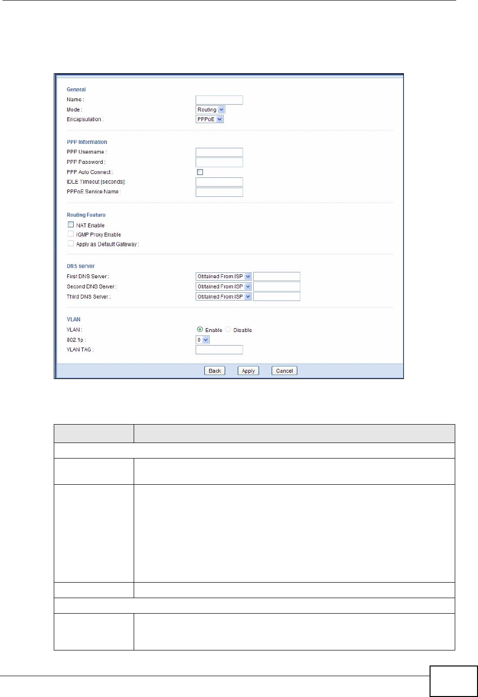
Chapter 7 Broadband
NVG2053 User’s Guide 87
This screen displays when you select the Routing mode and PPPoE
encapsulation.
Figure 30 Network > Broadband: PPPoE Encapsulation
The following table describes the labels in this screen.
Table 20 Network > Broadband: PPPoE Encapsulation
LABEL DESCRIPTION
General
Name Specify a descriptive name of up to 15 alphanumeric characters for this
connection.
Mode Select Routing (default) from the drop-down list box if your ISP give
you one IP address only and you want multiple computers to share an
Internet account.
Select Bridge when your ISP provides you more than one IP address
and you want the connected computers to get individual IP address
from ISP’s DHCP server directly. If you select Bridge, you cannot use
routing functions, such as QoS, Firewall, DHCP server and NAT on
traffic from the selected LAN port(s).
Encapsulation Select PPPoE for a dial-up connection.
PPP Information
PPP Username Enter the user name exactly as your ISP assigned. If assigned a name
in the form user@domain where domain identifies a service name, then
enter both components exactly as given.
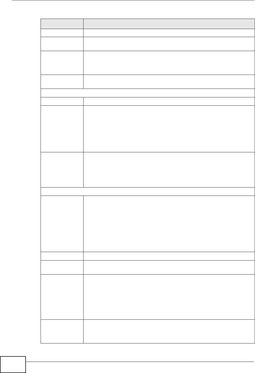
Chapter 7 Broadband
NVG2053 User’s Guide
88
PPP Password Enter the password associated with the user name above.
PPP Auto
Connect Select this option if you do not want the connection to time out.
IDLE Timeout This value specifies the time in minutes that elapses before the router
automatically disconnects from the PPPoE server.
This field is not configurable if you select PPP Auto Connect.
PPPoE Service
Name Enter the name of your PPPoE service here.
Routing Feature
NAT Enable Select this option to activate NAT on this connection.
IGMP Proxy
Enable Internet Group Multicast Protocol (IGMP) is a network-layer protocol
used to establish membership in a Multicast group - it is not used to
carry user data.
Select this option to have the NVG2053 act as an IGMP proxy on this
connection. This allows the NVG2053 to get subscribing information
and maintain a joined member list for each multicast group. It can
reduce multicast traffic significantly.
Apply as Default
Gateway Select this option to have the NVG2053 use the WAN interface of this
connection as the system default gateway.
This field is not configurable when another connection has been set to
be the deafult gateway through which the NVG2053 forwards the
traffic.
DNS Server
First DNS Server
Second DNS
Server
Third DNS
Server
Select Obtained From ISP if your ISP dynamically assigns DNS server
information (and the NVG2053's WAN IP address). The field to the right
displays the (read-only) DNS server IP address that the ISP assigns.
Select UserDefined if you have the IP address of a DNS server. Enter
the DNS server's IP address in the field to the right.
Select None if you do not want to configure DNS servers. If you do not
configure a DNS server, you must know the IP address of a computer in
order to access it.
VLAN
VLAN Select Enable to add the VLAN tag (specified below) to the outgoing
traffic through this connection. Otherwise, select Disable.
802.1p IEEE 802.1p defines up to 8 separate traffic types by inserting a tag
into a MAC-layer frame that contains bits to define class of service.
Type the IEEE 802.1p priority level (from 0 to 7) to add to traffic
through this connection. The greater the number, the higher the
priority level.
This field is configurable when you select Enable in the VLAN field.
VLAN TAG Type the VLAN ID number (from 1 to 4094) for traffic through this
connection.
This field is configurable when you select Enable in the VLAN field.
Table 20 Network > Broadband: PPPoE Encapsulation
LABEL DESCRIPTION
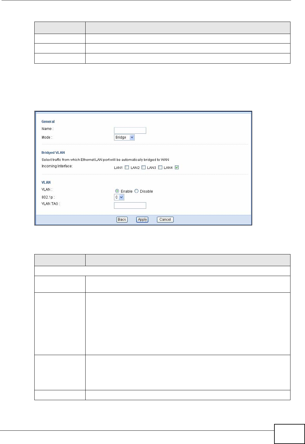
Chapter 7 Broadband
NVG2053 User’s Guide 89
7.3.2.1 Bridge
This screen displays when you select the Bridge mode.
Figure 31 Network > Broadband: Bridge mode
The following table describes the labels in this screen.
Back Click Back to return to the previous screen.
Apply Click Apply to save your changes back to the NVG2053.
Cancel Click Cancel to begin configuring this screen afresh.
Table 20 Network > Broadband: PPPoE Encapsulation
LABEL DESCRIPTION
Table 21 Network > Broadband: Bridge mode
LABEL DESCRIPTION
General
Name Specify a descriptive name of up to 15 alphanumeric characters for this
connection.
Mode Select Routing (default) from the drop-down list box if your ISP give
you one IP address only and you want multiple computers to share an
Internet account.
Select Bridge when your ISP provides you more than one IP address
and you want the connected computers to get individual IP address
from ISP’s DHCP server directly. If you select Bridge, you cannot use
routing functions, such as QoS, Firewall, DHCP server and NAT on
traffic from the selected LAN port(s).
Bridged VLAN Select the LAN port(s) from which traffic will be forwarded to the WAN
interface directly.
You cannot configure a QoS class for traffic from the LAN port which is
selected here.
VLAN
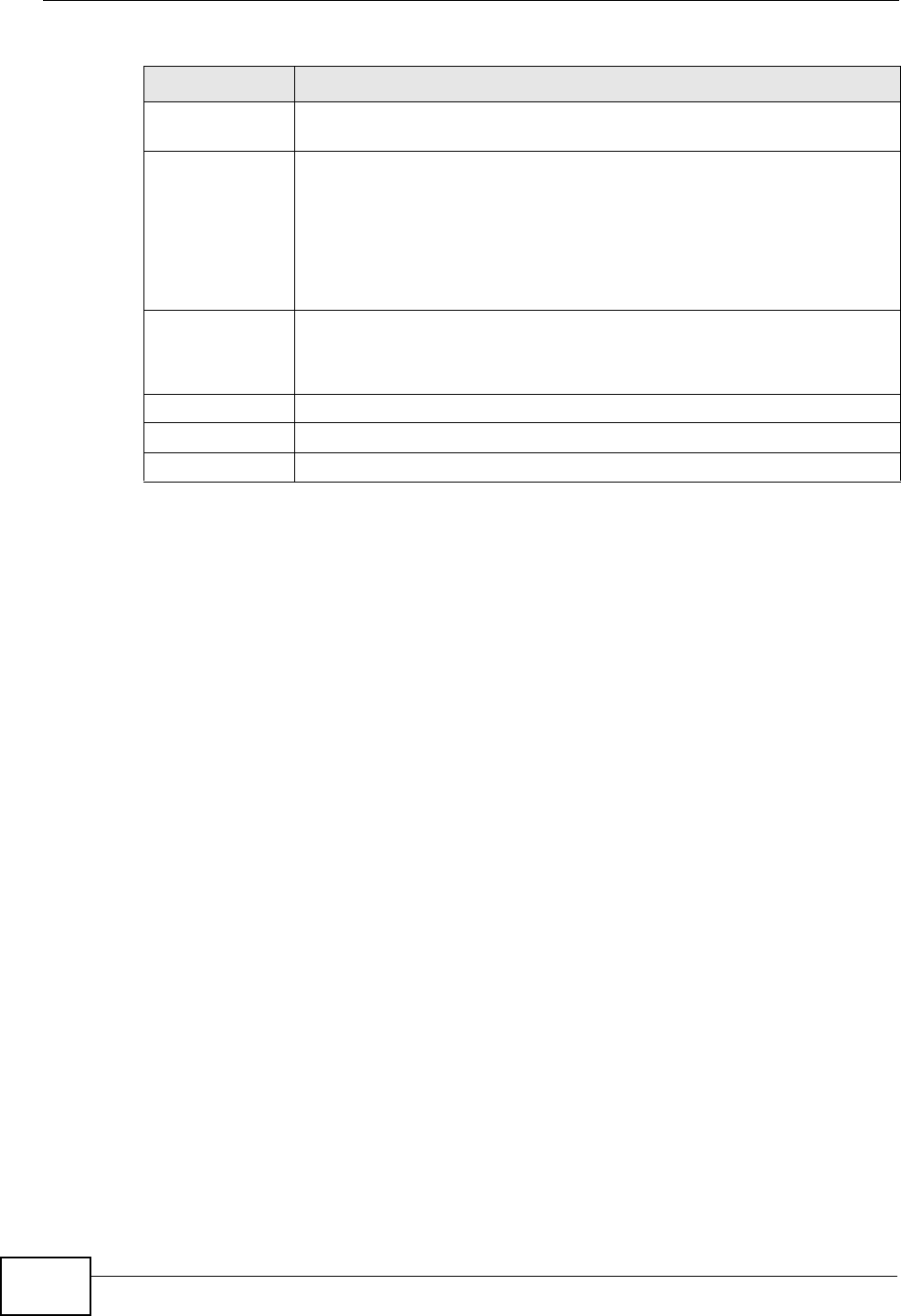
Chapter 7 Broadband
NVG2053 User’s Guide
90
7.4 Technical Reference
The following section contains additional technical information about the NVG2053
features described in this chapter.
Introduction to VLANs
A Virtual Local Area Network (VLAN) allows a physical network to be partitioned
into multiple logical networks. Devices on a logical network belong to one group. A
device can belong to more than one group. With VLAN, a device cannot directly
talk to or hear from devices that are not in the same group(s); the traffic must
first go through a router.
In Multi-Tenant Unit (MTU) applications, VLAN is vital in providing isolation and
security among the subscribers. When properly configured, VLAN prevents one
subscriber from accessing the network resources of another on the same LAN,
thus a user will not see the printers and hard disks of another user in the same
building.
VLAN also increases network performance by limiting broadcasts to a smaller and
more manageable logical broadcast domain. In traditional switched environments,
all broadcast packets go to each and every individual port. With VLAN, all
broadcasts are confined to a specific broadcast domain.
VLAN Select Enable to add the VLAN tag (specified below) to the outgoing
traffic through this connection. Otherwise, select Disable.
802.1p IEEE 802.1p defines up to 8 separate traffic types by inserting a tag
into a MAC-layer frame that contains bits to define class of service.
Type the IEEE 802.1p priority level (from 0 to 7) to add to traffic
through this connection. The greater the number, the higher the
priority level.
This field is configurable when you select Enable in the VLAN field.
VLAN TAG Type the VLAN ID number (from 1 to 4094) for traffic through this
connection.
This field is configurable when you select Enable in the VLAN field.
Back Click Back to return to the previous screen.
Apply Click Apply to save your changes back to the NVG2053.
Cancel Click Cancel to begin configuring this screen afresh.
Table 21 Network > Broadband: Bridge mode
LABEL DESCRIPTION

Chapter 7 Broadband
NVG2053 User’s Guide 91
Introduction to IEEE 802.1Q Tagged VLAN
A tagged VLAN uses an explicit tag (VLAN ID) in the MAC header to identify the
VLAN membership of a frame across bridges - they are not confined to the switch
on which they were created. The VLANs can be created statically by hand or
dynamically through GVRP. The VLAN ID associates a frame with a specific VLAN
and provides the information that switches need to process the frame across the
network. A tagged frame is four bytes longer than an untagged frame and
contains two bytes of TPID (Tag Protocol Identifier), residing within the type/
length field of the Ethernet frame) and two bytes of TCI (Tag Control Information),
starts after the source address field of the Ethernet frame).
The CFI (Canonical Format Indicator) is a single-bit flag, always set to zero for
Ethernet switches. If a frame received at an Ethernet port has a CFI set to 1, then
that frame should not be forwarded as it is to an untagged port. The remaining
twelve bits define the VLAN ID, giving a possible maximum number of 4,096
VLANs. Note that user priority and VLAN ID are independent of each other. A
frame with VID (VLAN Identifier) of null (0) is called a priority frame, meaning that
only the priority level is significant and the default VID of the ingress port is given
as the VID of the frame. Of the 4096 possible VIDs, a VID of 0 is used to identify
priority frames and value 4095 (FFF) is reserved, so the maximum possible VLAN
configurations are 4,094.
Multicast
IP packets are transmitted in either one of two ways - Unicast (1 sender - 1
recipient) or Broadcast (1 sender - everybody on the network). Multicast delivers
IP packets to a group of hosts on the network - not everybody and not just 1.
Internet Group Multicast Protocol (IGMP) is a network-layer protocol used to
establish membership in a Multicast group - it is not used to carry user data. IGMP
version 2 (RFC 2236) is an improvement over version 1 (RFC 1112) but IGMP
version 1 is still in wide use. If you would like to read more detailed information
about interoperability between IGMP version 2 and version 1, please see sections
4 and 5 of RFC 2236. The class D IP address is used to identify host groups and
can be in the range 224.0.0.0 to 239.255.255.255. The address 224.0.0.0 is not
assigned to any group and is used by IP multicast computers. The address
224.0.0.1 is used for query messages and is assigned to the permanent group of
all IP hosts (including gateways). All hosts must join the 224.0.0.1 group in order
to participate in IGMP. The address 224.0.0.2 is assigned to the multicast routers
group.
TPID
2 Bytes
User Priority
3 Bits
CFI
1 Bit
VLAN ID
12 Bits

Chapter 7 Broadband
NVG2053 User’s Guide
92
At start up, the NVG2053 queries all directly connected networks to gather group
membership. After that, the NVG2053 periodically updates this information.
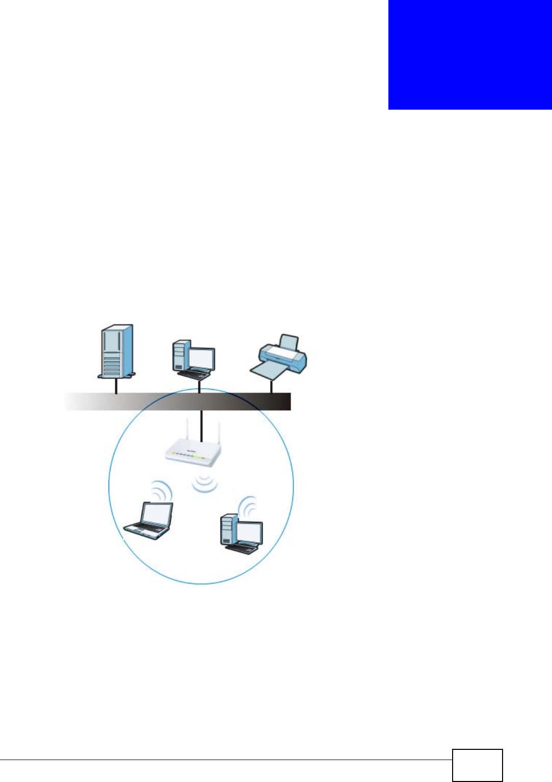
NVG2053 User’s Guide 93
CHAPTER 8
Wireless LAN
8.1 Overview
This chapter discusses how to configure the wireless network settings in your
NVG2053.
The following figure provides an example of a wireless network.
Figure 32 Example of a Wireless Network
The wireless network is the part in the blue circle. In this wireless network,
devices A and B are called wireless clients. The wireless clients use the access
point (AP) to interact with other devices (such as the printer) or with the Internet.
Your NVG2053 is the AP.
See Chapter 2 on page 33 for a tutorial showing how to set up your wireless
connection in an example scenario.
AB

Chapter 8 Wireless LAN
NVG2053 User’s Guide
94
See Section 8.10 on page 111 and Appendix C on page 275 for advanced technical
information on wireless networks.
8.1.1 What You Can Do in this Chapter
•Use the General screen (Section 8.3 on page 97) to enable the Wireless LAN,
enter the SSID and select the wireless security mode.
•Use the MAC Filter screen (Section 8.4 on page 104) to allow or deny wireless
clients based on their MAC addresses from connecting to the NVG2053.
•Use the Advanced screen (Section 8.5 on page 105) to allow wireless advanced
features, such as intra-BSS networking and set the RTS/CTS Threshold.
•Use the QoS screen (Section 8.6 on page 107) to have the NVG2053
automatically set priority levels to services, such as e-mail, VoIP, chat, and so
on.
•The WPS screen and the WPS Station screen let you use WiFi Protected Setup
(WPS) to quickly set up a wireless network with strong security, without having
to configure security settings manually.
Use the WPS screen (Section 8.7 on page 107) to enable or disable WPS,
generate a security PIN (Personal Identification Number) and see information
about the NVG2053’s WPS status.
Use the WPS Station (Section 8.8 on page 109) screen to add a wireless client
by pressing a button or using a PIN.
•Use the Scheduling screen (Section 8.9 on page 110) to set the times your
wireless LAN is turned on and off.
8.2 What You Need to Know
Every wireless network must follow these basic guidelines.
• Every wireless client in the same wireless network must use the same SSID.
The SSID is the name of the wireless network. It stands for Service Set IDentity.
• If two wireless networks overlap, they should use different channels.
Like radio stations or television channels, each wireless network uses a specific
channel, or frequency, to send and receive information.
• Every wireless client in the same wireless network must use security compatible
with the AP.
Security stops unauthorized devices from using the wireless network. It can also
protect the information that is sent in the wireless network.
Wireless Basics
“Wireless” is essentially radio communication. In the same way that walkie-talkie
radios send and receive information over the airwaves, wireless networking

Chapter 8 Wireless LAN
NVG2053 User’s Guide 95
devices exchange information with one another. A wireless networking device is
just like a radio that lets your computer exchange information with radios
attached to other computers. Like walkie-talkies, most wireless networking
devices operate at radio frequency bands that are open to the public and do not
require a license to use. However, wireless networking is different from that of
most traditional radio communications in that there a number of wireless
networking standards available with different methods of data encryption.
Wireless Network Construction
Wireless networks consist of wireless clients, access points and bridges.
• A wireless client is a radio connected to a user’s computer.
• An access point is a radio with a wired connection to a network, which can
connect with numerous wireless clients and let them access the network.
• A bridge is a radio that relays communications between access points and
wireless clients, extending a network’s range.
Traditionally, a wireless network operates in one of two ways.
• An “infrastructure” type of network has one or more access points and one or
more wireless clients. The wireless clients connect to the access points.
• An “ad-hoc” type of network is one in which there is no access point. Wireless
clients connect to one another in order to exchange information.
Network Names
Each network must have a name, referred to as the SSID - “Service Set
IDentifier”. The “service set” is the network, so the “service set identifier” is the
network’s name. This helps you identify your wireless network when wireless
networks’ coverage areas overlap and you have a variety of networks to choose
from.
Radio Channels
In the radio spectrum, there are certain frequency bands allocated for unlicensed,
civilian use. For the purposes of wireless networking, these bands are divided into
numerous channels. This allows a variety of networks to exist in the same place
without interfering with one another. When you create a network, you must select
a channel to use.
Since the available unlicensed spectrum varies from one country to another, the
number of available channels also varies.

Chapter 8 Wireless LAN
NVG2053 User’s Guide
96
Wireless Security
By their nature, radio communications are simple to intercept. For wireless data
networks, this means that anyone within range of a wireless network without
security can not only read the data passing over the airwaves, but also join the
network. Once an unauthorized person has access to the network she/he can
either steal information or introduce malware (malicious software) intended to
compromise the network. For these reasons, a variety of security systems have
been developed to ensure that only authorized people can use a wireless data
network, or understand the data carried on it.
These security standards do two things. First, they authenticate. This means that
only people presenting the right credentials (often a username and password, or a
“key” phrase) can access the network. Second, they encrypt. This means that the
information sent over the air is encoded. Only people with the code key can
understand the information, and only people who have been authenticated are
given the code key.
These security standards vary in effectiveness. Some can be broken, such as the
old Wired Equivalent Protocol (WEP). Using WEP is better than using no security at
all, but it will not keep a determined attacker out. Other security standards are
secure in themselves but can be broken if a user does not use them properly. For
example, the WPA-PSK security standard is perfectly secure if you use a long key
which is difficult for an attacker’s software to guess - for example, a twenty-letter
long string of apparently random numbers and letters - but it is not very secure if
you use a short key which is very easy to guess.
Because of the damage that can be done by a malicious attacker, it’s not just
people who have sensitive information on their network who should use security.
Everybody who uses any wireless network should ensure that effective security is
in place.
A good way to come up with effective security keys, passwords and so on is to use
obscure information that you personally will easily remember, and to enter it in a
way that appears random and does not include real words. For example, if your
mother owns a 1970 Dodge Challenger and her favorite movie is Vanishing Point
(which you know was made in 1971) you could use “70dodchal71vanpoi” as your
security key.
Signal Problems
Because wireless networks are radio networks, their signals are subject to
limitations of distance, interference and absorption.
Problems with distance occur when the two radios are too far apart. Problems with
interference occur when other radio waves interrupt the data signal. Interference
may come from other radio transmissions, such as military or air traffic control
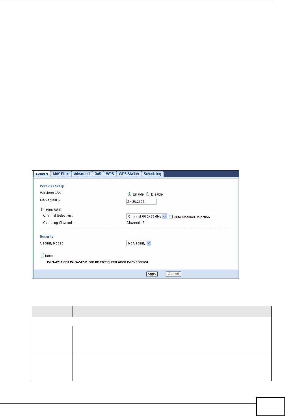
Chapter 8 Wireless LAN
NVG2053 User’s Guide 97
communications, or from machines that are coincidental emitters such as electric
motors or microwaves. Problems with absorption occur when physical objects
(such as thick walls) are between the two radios, muffling the signal.
8.3 General Wireless LAN Screen
Use this screen to enable the Wireless LAN, enter the SSID and select the wireless
security mode.
Note: If you are configuring the NVG2053 from a computer connected to the wireless
LAN and you change the NVG2053’s SSID, channel or security settings, you
will lose your wireless connection when you press Apply to confirm. You must
then change the wireless settings of your computer to match the NVG2053’s
new settings.
Click Network > Wireless LAN to open the General screen.
Figure 33 Network > Wireless LAN > General
The following table describes the general wireless LAN labels in this screen.
Table 22 Network > Wireless LAN > General
LABEL DESCRIPTION
Wireless Setup
Wireless LAN This is turned on by default.
You can turn the wireless LAN on or off using the switch at the rear panel
of the NVG2053. The current wireless state is reflected in this field.
Name(SSID) The SSID (Service Set IDentity) identifies the service set with which a
wireless device is associated. Wireless devices associating to the access
point (AP) must have the same SSID. Enter a descriptive name (up to 32
English keyboard characters) for the wireless LAN.
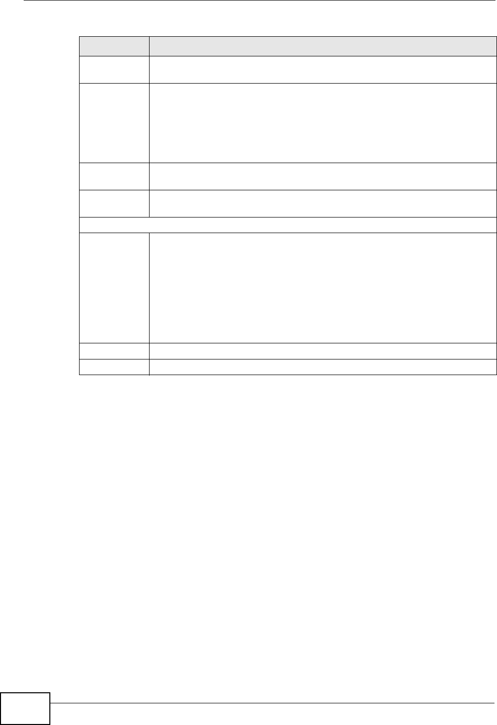
Chapter 8 Wireless LAN
NVG2053 User’s Guide
98
8.3.1 No Security
Select No Security to allow wireless stations to communicate with the access
points without any data encryption or authentication.
Hide SSID Select this check box to hide the SSID in the outgoing beacon frame so a
station cannot obtain the SSID through scanning using a site survey tool.
Channel
Selection Select a channel from the drop-down list box. The options vary depending
on the frequency band and the country you are in. If you are having
problems with wireless interference, changing the channel may help. Try
to use a channel that is as many channels away from any channels used
by neighboring APs as possible.
This option is only available if Auto Channel Selection is disabled.
Auto Channel
Selection Select this option to have the NVG2053 automatically determine a channel
to use.
Operating
Channel This displays the channel the NVG2053 is currently using.
Security
Security
Mode Select Static WEP, WPA-PSK, WPA, WPA2-PSK or WPA2 to add
security on this wireless network. The wireless clients which want to
associate to this network must have same wireless security settings as the
NVG2053. After you select to use a security, additional options appears in
this screen.
Or you can select No Security to allow any client to associate this
network without any data encryption or authentication.
See the following sections for more details about this field.
Apply Click Apply to save your changes back to the NVG2053.
Cancel Click Cancel to reload the previous configuration for this screen.
Table 22 Network > Wireless LAN > General
LABEL DESCRIPTION
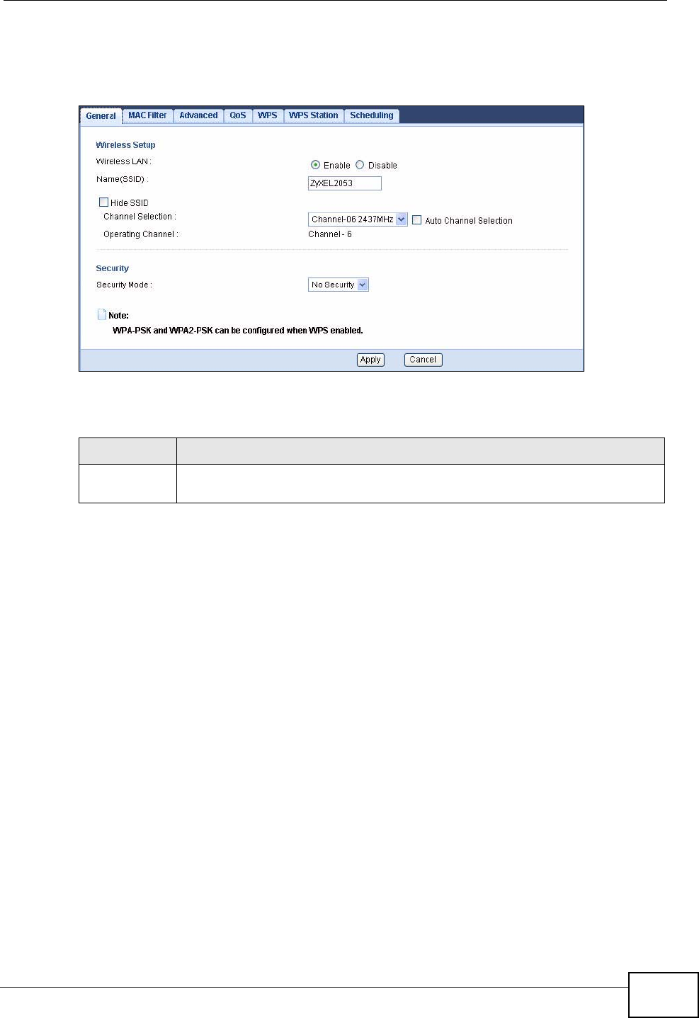
Chapter 8 Wireless LAN
NVG2053 User’s Guide 99
Note: If you do not enable any wireless security on your NVG2053, your network is
accessible to any wireless networking device that is within range.
Figure 34 Network > Wireless LAN > General: No Security
The following table describes the labels in this screen.
8.3.2 WEP Encryption
Your NVG2053 allows you to configure up to four 64-bit or 128-bit WEP keys but
only one key can be enabled at any one time.
Table 23 Network > Wireless LAN > General: No Security
LABEL DESCRIPTION
Security
Mode Choose No Security from the drop-down list box.
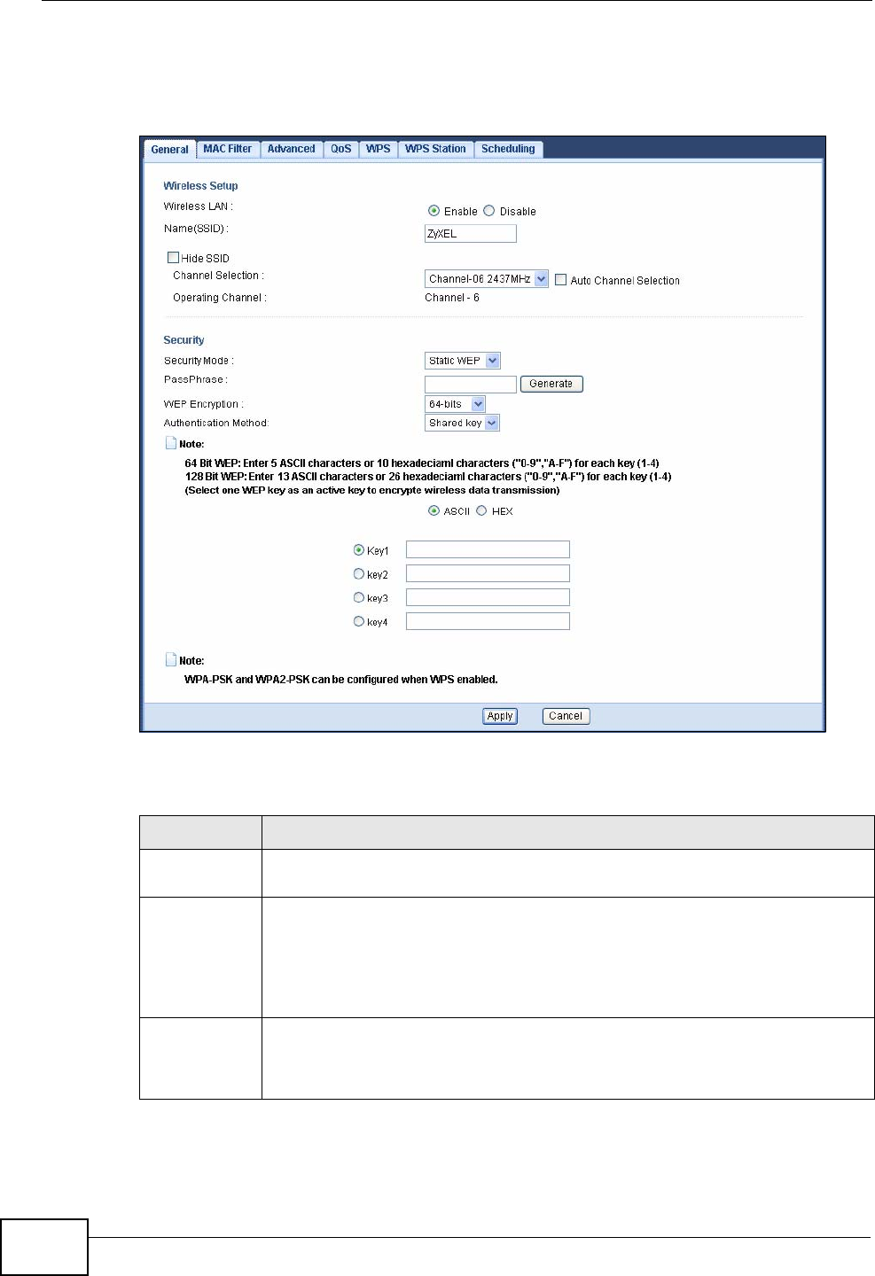
Chapter 8 Wireless LAN
NVG2053 User’s Guide
100
In order to configure and enable WEP encryption, click Network > Wireless LAN
to display the General screen. Select Static WEP from the Security Mode list.
Figure 35 Network > Wireless LAN > General: Static WEP
The following table describes the wireless LAN security labels in this screen.
Table 24 Network > Wireless LAN > General: Static WEP
LABEL DESCRIPTION
Security
Mode Select Static WEP to enable data encryption.
PassPhrase Enter a Passphrase (up to 26 printable characters) and click Generate.
A passphrase functions like a password. In WEP security mode, it is further
converted by the NVG2053 into a complicated string that is referred to as
the “key”. This key is requested from all devices wishing to connect to a
wireless network.
WEP
Encryption Select 64-bits or 128-bits.
This dictates the length of the security key that the network is going to
use.
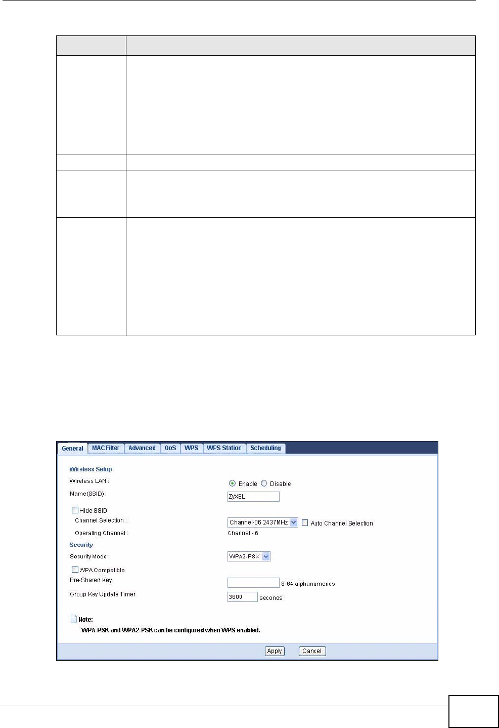
Chapter 8 Wireless LAN
NVG2053 User’s Guide 101
8.3.3 WPA(2)-PSK
Click Network > Wireless LAN to display the General screen. Select WPA-PSK
or WPA2-PSK from the Security Mode list.
Figure 36 Network > Wireless LAN > General: WPA(2)-PSK
Authenticatio
n Method Select Auto or Shared Key from the drop-down list box.
This field specifies whether the wireless clients have to provide the WEP
key to login to the wireless network. Keep this setting at Auto unless you
want to force a key verification before communication between the
wireless client and the NVG2053 occurs.
Select Shared Key to force the clients to provide the WEP key prior to
communication.
ASCII Select this option in order to enter ASCII characters as WEP key.
HEX Select this option in order to enter hexadecimal characters as a WEP key.
The preceding "0x", that identifies a hexadecimal key, is entered
automatically.
Key 1 to Key
4The WEP keys are used to encrypt data. Both the NVG2053 and the
wireless stations must use the same WEP key for data transmission.
If you chose 64-bits, then enter any 5 ASCII characters or 10
hexadecimal characters ("0-9", "A-F").
If you chose 128-bits, then enter 13 ASCII characters or 26 hexadecimal
characters ("0-9", "A-F").
You must configure at least one key, only one key can be activated at any
one time. The default key is key 1.
Table 24 Network > Wireless LAN > General: Static WEP
LABEL DESCRIPTION
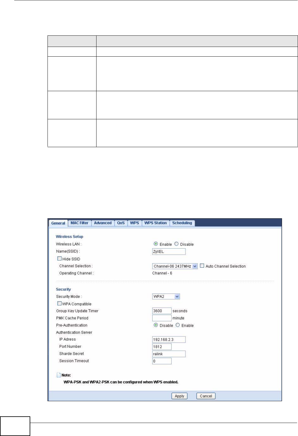
Chapter 8 Wireless LAN
NVG2053 User’s Guide
102
The following table describes the labels in this screen.
8.3.4 WPA(2) Authentication
Use this screen to configure and enable WPA or WPA2 authentication; click the
Wireless LAN link under Network to display the General screen. Select WPA or
WPA2 from the Security Mode list.
Figure 37 Wireless LAN > General: WPA(2)
Table 25 Network > Wireless LAN > General: WPA(2)-PSK
LABEL DESCRIPTION
Security Mode Select WPA-PSK or WPA2-PSK to enable data encryption.
WPA
Compatible This field appears when you choose WPA-PSK2 as the Security Mode.
Check this field to allow wireless devices using WPA-PSK security
mode to connect to your NVG2053. The NVG2053 supports WPA-PSK
and WPA2-PSK simultaneously.
Pre-Shared Key WPA-PSK/WPA2-PSK uses a simple common password for
authentication.
Type a pre-shared key from 8 to 63 case-sensitive keyboard characters.
Group Key
Update Timer The Group Key Update Timer is the rate at which the AP sends a new
group key out to all clients.
The default is 3600 seconds (60 minutes).

Chapter 8 Wireless LAN
NVG2053 User’s Guide 103
The following table describes the wireless LAN security labels in this screen.
Table 26 Wireless LAN > General: WPA(2)
LABEL DESCRIPTION
Security Mode Choose WPA or WPA2 from the drop-down list box.
WPA Compatible This field is only available for WPA2. Select this if you want the
NVG2053 to support WPA and WPA2 simultaneously.
Group Key
Update Timer The Group Key Update Timer is the rate at which the RADIUS server
sends a new group key out to all clients.
PMK Cache
Period This field is available only when you select WPA2.
Specify how often wireless clients have to resend usernames and
passwords in order to stay connected. Enter a time interval between
10 and 999999 minutes.
Note: If wireless client authentication is done using a RADIUS
server, the reauthentication timer on the RADIUS server has
priority.
Pre-
Authentication This field is available only when you select WPA2.
Pre-authentication enables fast roaming by allowing the wireless client
(already connecting to an AP) to perform IEEE 802.1x authentication
with another AP before connecting to it. Select Enabled to turn on
preauthentication in WAP2. Otherwise, select Disabled.
Authentication Server
IP Address Enter the IP address of the external authentication server in dotted
decimal notation.
Port Number Enter the port number of the external authentication server. The
default port number is 1812.
You need not change this value unless your network administrator
instructs you to do so with additional information.
Shared Secret Enter a password (up to 31 alphanumeric characters) as the key to be
shared between the external authentication server and the NVG2053.
The key must be the same on the external authentication server and
your NVG2053. The key is not sent over the network.
Session
Timeout The NVG2053 automatically disconnects a wireless client from the
wireless and wired networks after a period of inactivity. The wireless
client needs to send the username and password again before it can
use the wireless and wired networks again. Some wireless clients may
prompt users for a username and password; other clients may use
saved login credentials. In either case, there is usually a short delay
while the wireless client logs in to the wireless network again.
Enter the time in seconds from 0 to 999999.
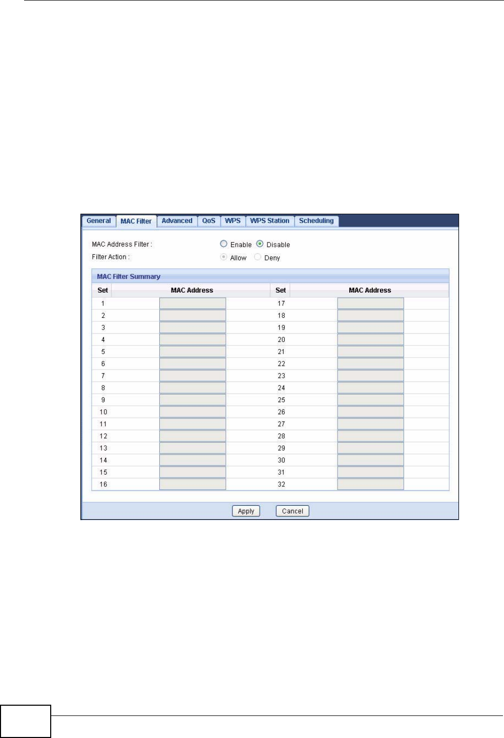
Chapter 8 Wireless LAN
NVG2053 User’s Guide
104
8.4 MAC Filter
The MAC filter screen allows you to configure the NVG2053 to give exclusive
access to devices (Allow) or exclude devices from accessing the NVG2053
(Deny). Every Ethernet device has a unique MAC (Media Access Control) address.
The MAC address is assigned at the factory and consists of six pairs of
hexadecimal characters, for example, 00:A0:C5:00:00:02. You need to know the
MAC address of the devices to configure this screen.
To change your NVG2053’s MAC filter settings, click Network > Wireless LAN >
MAC Filter. The screen appears as shown.
Figure 38 Network > Wireless LAN > MAC Filter
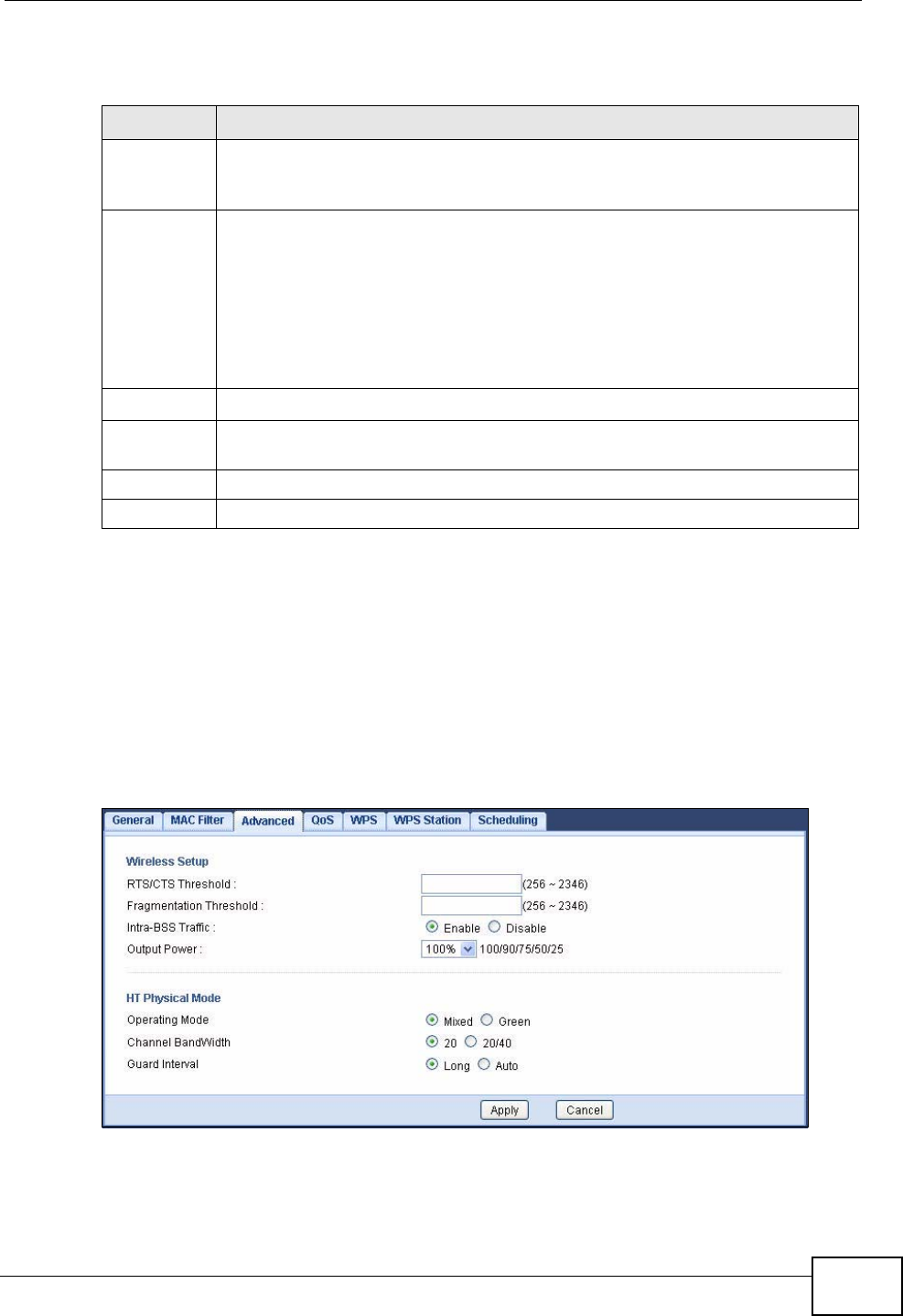
Chapter 8 Wireless LAN
NVG2053 User’s Guide 105
The following table describes the labels in this menu.
8.5 Wireless LAN Advanced Screen
Use this screen to allow wireless advanced features, such as intra-BSS networking
and set the RTS/CTS Threshold
Click Network > Wireless LAN > Advanced. The screen appears as shown.
Figure 39 Network > Wireless LAN > Advanced
Table 27 Network > Wireless LAN > MAC Filter
LABEL DESCRIPTION
MAC
Address
Filter
Select to turn on (Enable) or off (Disable) MAC address filtering.
Filter Action Define the filter action for the list of MAC addresses in the MAC Filter
Summary table. This field is configurable only when you select Enable in
the MAC Address Filter field.
Select Allow to permit access to the NVG2053, MAC addresses not listed
will be denied access to the NVG2053.
Select Deny to block access to the NVG2053, MAC addresses not listed will
be allowed to access the NVG2053
Set This is the index number of the MAC address.
MAC
Address Enter the MAC addresses of the wireless devices that are allowed or denied
access to the NVG2053.
Apply Click Apply to save your changes back to the NVG2053.
Cancel Click Cancel to reload the previous configuration for this screen.
Chapter 8 Wireless LAN
NVG2053 User’s Guide
106
The following table describes the labels in this screen.
Table 28 Network > Wireless LAN > Advanced
LABEL DESCRIPTION
RTS/CTS
Threshold Data with its frame size larger than this value will perform the RTS
(Request To Send)/CTS (Clear To Send) handshake.
Enter a value between 256 and 2346.
Fragmentation
Threshold The threshold (number of bytes) for the fragmentation boundary for
directed messages. It is the maximum data fragment size that can be
sent. Enter an even number between 256 and 2346.
Intra-BSS
Traffic A Basic Service Set (BSS) exists when all communications between
wireless clients or between a wireless client and a wired network client go
through one access point (AP).
Intra-BSS traffic is traffic between wireless clients in the BSS. When
Intra-BSS is enabled, wireless clients can access the wired network and
communicate with each other. When Intra-BSS is disabled, wireless
clients can still access the wired network but cannot communicate with
each other.
Output Power Set the output power of the NVG2053 in this field. If there is a high
density of APs in an area, decrease the output power of the NVG2053 to
reduce interference with other APs. Select one of the following 100%,
90%, 75%, 50% or 25%. See the product specifications for more
information on your NVG2053’s output power.
HT (High Throughput) Physical Mode - Use the fields below to configure the 802.11
wireless environment of your NVG2053.
Operating
Mode Choose this according to the wireless mode(s) used in your network.
Mixed - Select this if the wireless clients in your network use different
wireless modes (for example, IEEE 802.11b/g and IEEE 802.1n modes)
Green - Select this if the wireless clients in your network uses only one
type of wireless mode (for example, IEEEE 802.11 n only)
Channel
Bandwidth Select the channel bandwidth you want to use for your wireless network.
It is recommended that you select 20/40 (20/40 MHz).
Select 20 MHz if you want to lessen radio interference with other wireless
devices in your neighborhood.
Guard Interval Select Auto to increase data throughput. However, this may make data
transfer more prone to errors.
Select Long to prioritize data integrity. This may be because your
wireless network is busy and congested or the NVG2053 is located in an
environment prone to radio interference.
Apply Click Apply to save your changes back to the NVG2053.
Cancel Click Cancel to reload the previous configuration for this screen.
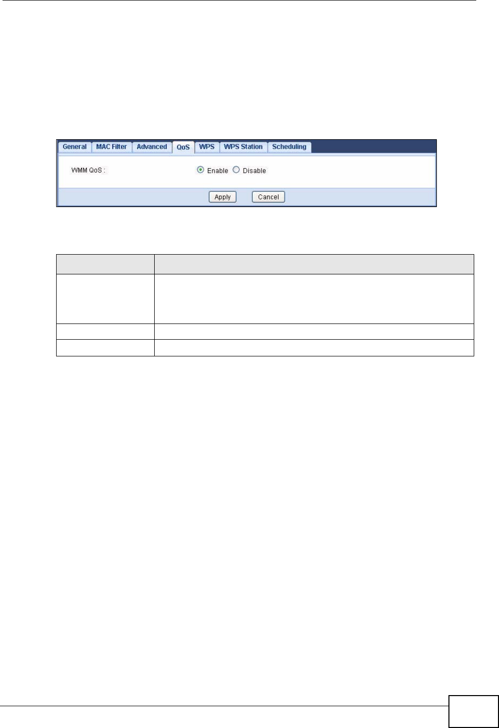
Chapter 8 Wireless LAN
NVG2053 User’s Guide 107
8.6 Quality of Service (QoS) Screen
The QoS screen allows you to automatically give a service (such as VoIP and
video) a priority level.
Click Network > Wireless LAN > QoS. The following screen appears.
Figure 40 Network > Wireless LAN > QoS
The following table describes the labels in this screen.
8.7 WPS Screen
Use this screen to enable/disable WPS, view or generate a new PIN number and
check current WPS status. To open this screen, click Network > Wireless LAN >
WPS tab.
Table 29 Network > Wireless LAN > QoS
LABEL DESCRIPTION
WMM QoS Select Enable to have the NVG2053 automatically give a service a
priority level according to the ToS value in the IP header of packets
it sends. WMM QoS (Wifi MultiMedia Quality of Service) gives high
priority to voice and video, which makes them run more smoothly.
Apply Click Apply to save your changes to the NVG2053.
Cancel Click Cancel to reload the previous configuration for this screen.
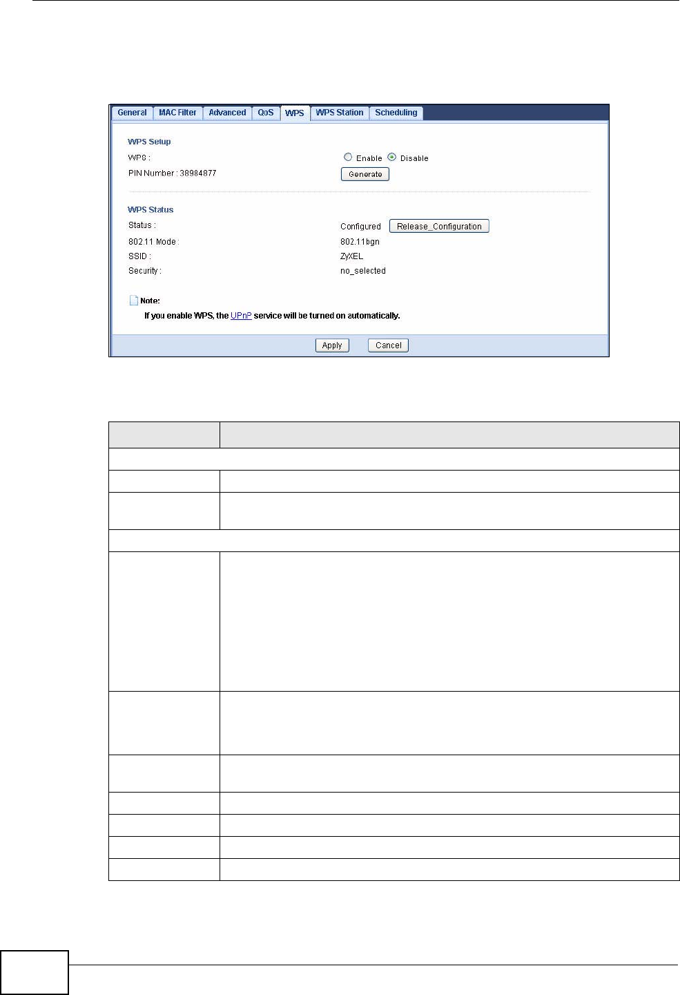
Chapter 8 Wireless LAN
NVG2053 User’s Guide
108
Note: WPS works only when you set the wireless security mode to WPA-PSK or
WPA2-PSK in the Wireless LAN > General screen.
Figure 41 Network > Wireless LAN > WPS
The following table describes the labels in this screen.
Table 30 Network > Wireless LAN > WPS
LABEL DESCRIPTION
WPS Setup
WPS Select Enable to turn on the WPS feature. Otherwise, select Disable.
PIN Number This displays a PIN number last time system generated. Click Generate
to generate a new PIN number.
WPS Status
Status This displays Configured when the NVG2053 has connected to a
wireless network using WPS or when Enable WPS is selected and
wireless or wireless security settings have been changed. The current
wireless and wireless security settings also appear in the screen.
This displays Unconfigured if WPS is disabled and there are no
wireless or wireless security changes on the NVG2053 or you click
Release_Configuration to remove the configured wireless and
wireless security settings.
Release
Configuration This button is only available when the WPS status displays Configured.
Click this button to remove all configured wireless and wireless security
settings for WPS connections on the NVG2053.
802.11 Mode This is the 802.11 mode used. Only compliant WLAN devices can
associate with the NVG2053.
SSID This is the name of the wireless network.
Security This is the type of wireless security employed by the network.
Apply Click Apply to save your changes back to the NVG2053.
Cancel Click Cancel to get this screen information afresh.
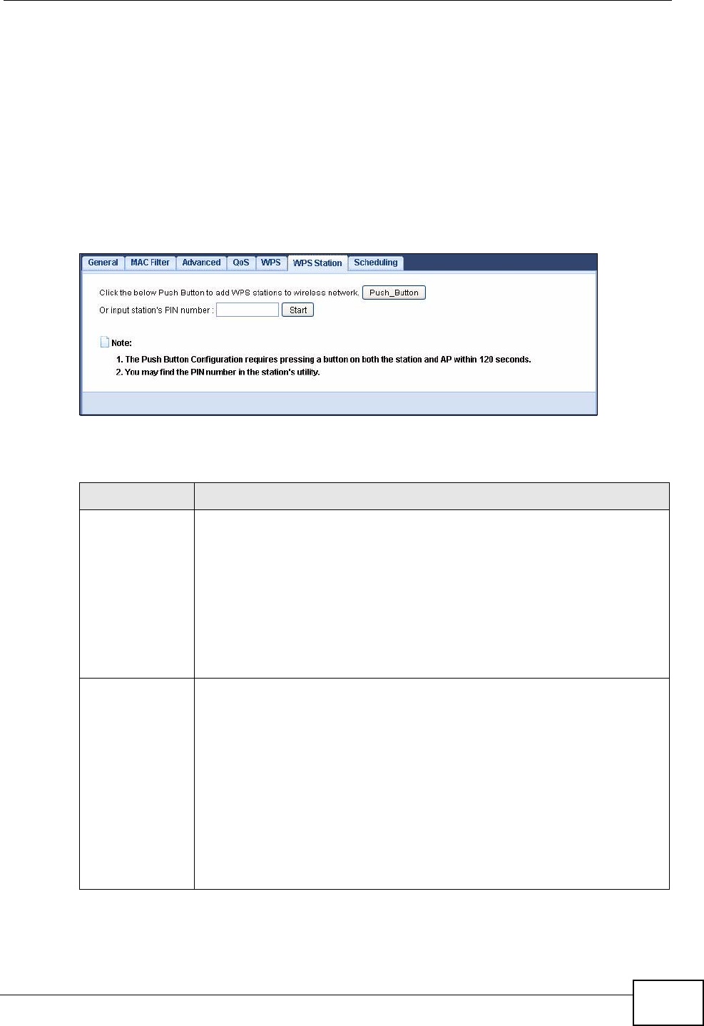
Chapter 8 Wireless LAN
NVG2053 User’s Guide 109
8.8 WPS Station Screen
Use this screen when you want to add a wireless station using WPS. To open this
screen, click Network > Wireless LAN > WPS Station tab.
Note: After you click Push Button on this screen, you have to press a similar button
in the wireless station utility within 2 minutes. To add the second wireless
station, you have to press these buttons on both device and the wireless station
again after the first 2 minutes.
Figure 42 Network > Wireless LAN > WPS Station
The following table describes the labels in this screen.
Table 31 Network > Wireless LAN > WPS Station
LABEL DESCRIPTION
Push Button Use this button when you use the PBC (Push Button Configuration)
method to add another WPS-enabled wireless device (within wireless
range of the NVG2053) to your wireless network. See Section 8.10.3.1
on page 114.
Click this to start WPS-aware wireless station scanning and the wireless
security information synchronization.
Note: You must press the other wireless device’s WPS button
within two minutes of pressing this button.
Or input
station's PIN
number
Use this button when you use the PIN Configuration method to
configure wireless station’s wireless settings. See Section 8.10.3.2 on
page 115.
Enter the PIN of the device that you are setting up a WPS connection
with and click Start to authenticate and add the wireless device to your
wireless network.
You can find the PIN either on the outside of the device, or by checking
the device’s settings.
Note: You must also activate WPS on that device within two
minutes to have it present its PIN to the NVG2053.
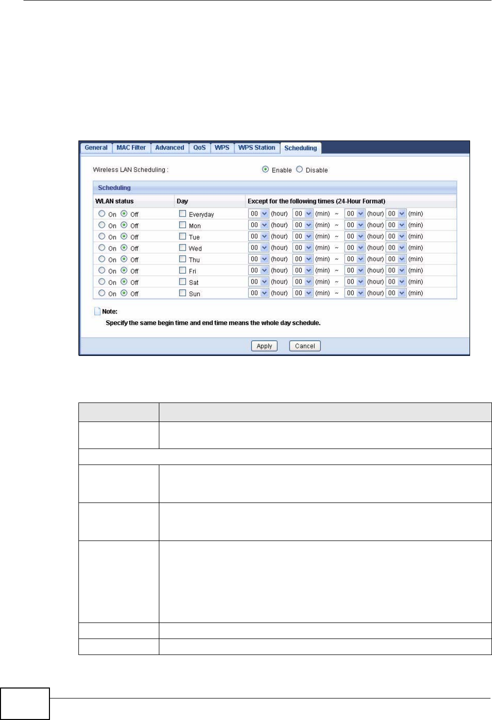
Chapter 8 Wireless LAN
NVG2053 User’s Guide
110
8.9 Scheduling Screen
Use this screen to set the times your wireless LAN is turned on and off. Wireless
LAN scheduling is disabled by default. The wireless LAN can be scheduled to turn
on or off on certain days and at certain times. To open this screen, click Network
> Wireless LAN > Scheduling tab.
Figure 43 Network > Wireless LAN > Scheduling
The following table describes the labels in this screen.
Table 32 Network > Wireless LAN > Scheduling
LABEL DESCRIPTION
Wireless LAN
Scheduling Select Enable to activate wireless LAN scheduling. Otherwise, select
Disable.
Scheduling
WLAN Status Select On or Off to specify whether the Wireless LAN is turned on or off.
This field works in conjunction with the Day and Except for the
following times fields.
Day Select Everyday or the specific days to turn the Wireless LAN on or off.
If you select Everyday you can not select any specific days. This field
works in conjunction with the Except for the following times field.
Except for the
following times
(24-Hour
Format)
Select a begin time using the first set of hour and minute (min) drop
down boxes and select an end time using the second set of hour and
minute (min) drop down boxes. If you have chosen On earlier for the
WLAN Status the Wireless LAN will turn on between the two times you
enter in these fields. If you have chosen Off earlier for the WLAN
Status the Wireless LAN will turn off between the two times you enter
in these fields.
Apply Click Apply to save your changes back to the NVG2053.
Cancel Click Cancel to reload the previous configuration for this screen.

Chapter 8 Wireless LAN
NVG2053 User’s Guide 111
8.10 Technical Reference
This section discusses wireless LANs in depth. For more information, see the
appendix.
8.10.1 Additional Wireless Terms
The following table describes some wireless network terms and acronyms used in
the NVG2053’s Web Configurator.
8.10.2 Wireless Security Overview
The following sections introduce different types of wireless security you can set up
in the wireless network.
8.10.2.1 SSID
Normally, the NVG2053 acts like a beacon and regularly broadcasts the SSID in
the area. You can hide the SSID instead, in which case the NVG2053 does not
broadcast the SSID. In addition, you should change the default SSID to something
that is difficult to guess.
Table 33 Additional Wireless Terms
TERM DESCRIPTION
RTS/CTS Threshold In a wireless network which covers a large area, wireless devices
are sometimes not aware of each other’s presence. This may cause
them to send information to the AP at the same time and result in
information colliding and not getting through.
By setting this value lower than the default value, the wireless
devices must sometimes get permission to send information to the
NVG2053. The lower the value, the more often the devices must get
permission.
If this value is greater than the fragmentation threshold value (see
below), then wireless devices never have to get permission to send
information to the NVG2053.
Preamble A preamble affects the timing in your wireless network. There are
two preamble modes: long and short. If a device uses a different
preamble mode than the NVG2053 does, it cannot communicate
with the NVG2053.
Authentication The process of verifying whether a wireless device is allowed to use
the wireless network.
Fragmentation
Threshold A small fragmentation threshold is recommended for busy networks,
while a larger threshold provides faster performance if the network
is not very busy.

Chapter 8 Wireless LAN
NVG2053 User’s Guide
112
This type of security is fairly weak, however, because there are ways for
unauthorized wireless devices to get the SSID. In addition, unauthorized wireless
devices can still see the information that is sent in the wireless network.
8.10.2.2 MAC Address Filter
Every device that can use a wireless network has a unique identification number,
called a MAC address.1 A MAC address is usually written using twelve hexadecimal
characters2; for example, 00A0C5000002 or 00:A0:C5:00:00:02. To get the MAC
address for each device in the wireless network, see the device’s User’s Guide or
other documentation.
You can use the MAC address filter to tell the NVG2053 which devices are allowed
or not allowed to use the wireless network. If a device is allowed to use the
wireless network, it still has to have the correct information (SSID, channel, and
security). If a device is not allowed to use the wireless network, it does not matter
if it has the correct information.
This type of security does not protect the information that is sent in the wireless
network. Furthermore, there are ways for unauthorized wireless devices to get the
MAC address of an authorized device. Then, they can use that MAC address to use
the wireless network.
8.10.2.3 User Authentication
Authentication is the process of verifying whether a wireless device is allowed to
use the wireless network. You can make every user log in to the wireless network
before they can use it. However, every device in the wireless network has to
support IEEE 802.1x to do this.
For wireless networks, you can store the user names and passwords for each user
in a RADIUS server. This is a server used in businesses more than in homes. If you
do not have a RADIUS server, you cannot set up user names and passwords for
your users.
Unauthorized wireless devices can still see the information that is sent in the
wireless network, even if they cannot use the wireless network. Furthermore,
there are ways for unauthorized wireless users to get a valid user name and
password. Then, they can use that user name and password to use the wireless
network.
1. Some wireless devices, such as scanners, can detect wireless networks but cannot use wireless networks.
These kinds of wireless devices might not have MAC addresses.
2. Hexadecimal characters are 0, 1, 2, 3, 4, 5, 6, 7, 8, 9, A, B, C, D, E, and F.

Chapter 8 Wireless LAN
NVG2053 User’s Guide 113
8.10.2.4 Encryption
Wireless networks can use encryption to protect the information that is sent in the
wireless network. Encryption is like a secret code. If you do not know the secret
code, you cannot understand the message.
The types of encryption you can choose depend on the type of authentication.
(See Section 8.10.2.3 on page 112 for information about this.)
For example, if the wireless network has a RADIUS server, you can choose WPA
or WPA2. If users do not log in to the wireless network, you can choose no
encryption, Static WEP, WPA-PSK, or WPA2-PSK.
Usually, you should set up the strongest encryption that every device in the
wireless network supports. For example, suppose you have a wireless network
with the NVG2053 and you do not have a RADIUS server. Therefore, there is no
authentication. Suppose the wireless network has two devices. Device A only
supports WEP, and device B supports WEP and WPA. Therefore, you should set up
Static WEP in the wireless network.
Note: It is recommended that wireless networks use WPA-PSK, WPA, or stronger
encryption. The other types of encryption are better than none at all, but it is still
possible for unauthorized wireless devices to figure out the original information
pretty quickly.
When you select WPA2 or WPA2-PSK in your NVG2053, you can also select an
option (WPA compatible) to support WPA as well. In this case, if some of the
devices support WPA and some support WPA2, you should set up WPA2-PSK or
WPA2 (depending on the type of wireless network login) and select the WPA
compatible option in the NVG2053.
Many types of encryption use a key to protect the information in the wireless
network. The longer the key, the stronger the encryption. Every device in the
wireless network must have the same key.
Table 34 Types of Encryption for Each Type of Authentication
NO AUTHENTICATION RADIUS SERVER
Weakest No Security
WPA
Static WEP
WPA-PSK
Stronges
tWPA2-PSK WPA2

Chapter 8 Wireless LAN
NVG2053 User’s Guide
114
8.10.3 WiFi Protected Setup
Your NVG2053 supports WiFi Protected Setup (WPS), which is an easy way to set
up a secure wireless network. WPS is an industry standard specification, defined
by the WiFi Alliance.
WPS allows you to quickly set up a wireless network with strong security, without
having to configure security settings manually. Each WPS connection works
between two devices. Both devices must support WPS (check each device’s
documentation to make sure).
Depending on the devices you have, you can either press a button (on the device
itself, or in its configuration utility) or enter a PIN (a unique Personal Identification
Number that allows one device to authenticate the other) in each of the two
devices. When WPS is activated on a device, it has two minutes to find another
device that also has WPS activated. Then, the two devices connect and set up a
secure network by themselves.
8.10.3.1 Push Button Configuration
WPS Push Button Configuration (PBC) is initiated by pressing a button on each
WPS-enabled device, and allowing them to connect automatically. You do not need
to enter any information.
Not every WPS-enabled device has a physical WPS button. Some may have a WPS
PBC button in their configuration utilities instead of or in addition to the physical
button.
Take the following steps to set up WPS using the button.
1Ensure that the two devices you want to set up are within wireless range of one
another.
2Look for a WPS button on each device. If the device does not have one, log into its
configuration utility and locate the button (see the device’s User’s Guide for how to
do this - for the NVG2053, see Section 8.8 on page 109).
3Press the button on one of the devices (it doesn’t matter which). For the NVG2053
you must press the WPS button for more than three seconds.
4Within two minutes, press the button on the other device. The registrar sends the
network name (SSID) and security key through an secure connection to the
enrollee.
If you need to make sure that WPS worked, check the list of associated wireless
clients in the AP’s configuration utility. If you see the wireless client in the list,
WPS was successful.

Chapter 8 Wireless LAN
NVG2053 User’s Guide 115
8.10.3.2 PIN Configuration
Each WPS-enabled device has its own PIN (Personal Identification Number). This
may either be static (it cannot be changed) or dynamic (in some devices you can
generate a new PIN by clicking on a button in the configuration interface).
Use the PIN method instead of the push-button configuration (PBC) method if you
want to ensure that the connection is established between the devices you specify,
not just the first two devices to activate WPS in range of each other. However, you
need to log into the configuration interfaces of both devices to use the PIN
method.
When you use the PIN method, you must enter the PIN from one device (usually
the wireless client) into the second device (usually the Access Point or wireless
router). Then, when WPS is activated on the first device, it presents its PIN to the
second device. If the PIN matches, one device sends the network and security
information to the other, allowing it to join the network.
Take the following steps to set up a WPS connection between an access point or
wireless router (referred to here as the AP) and a client device using the PIN
method.
1Ensure WPS is enabled on both devices.
2Access the WPS section of the AP’s configuration interface. See the device’s User’s
Guide for how to do this.
3Look for the client’s WPS PIN; it will be displayed either on the device, or in the
WPS section of the client’s configuration interface (see the device’s User’s Guide
for how to find the WPS PIN - for the NVG2053, see Section 8.7 on page 107).
4Enter the client’s PIN in the AP’s configuration interface.
Note: If the client device’s configuration interface has an area for entering another
device’s PIN, you can either enter the client’s PIN in the AP, or enter the AP’s
PIN in the client - it does not matter which.
5Start WPS on both devices within two minutes.
Note: Use the configuration utility to activate WPS, not the push-button on the device
itself.
6On a computer connected to the wireless client, try to connect to the Internet. If
you can connect, WPS was successful.
If you cannot connect, check the list of associated wireless clients in the AP’s
configuration utility. If you see the wireless client in the list, WPS was successful.
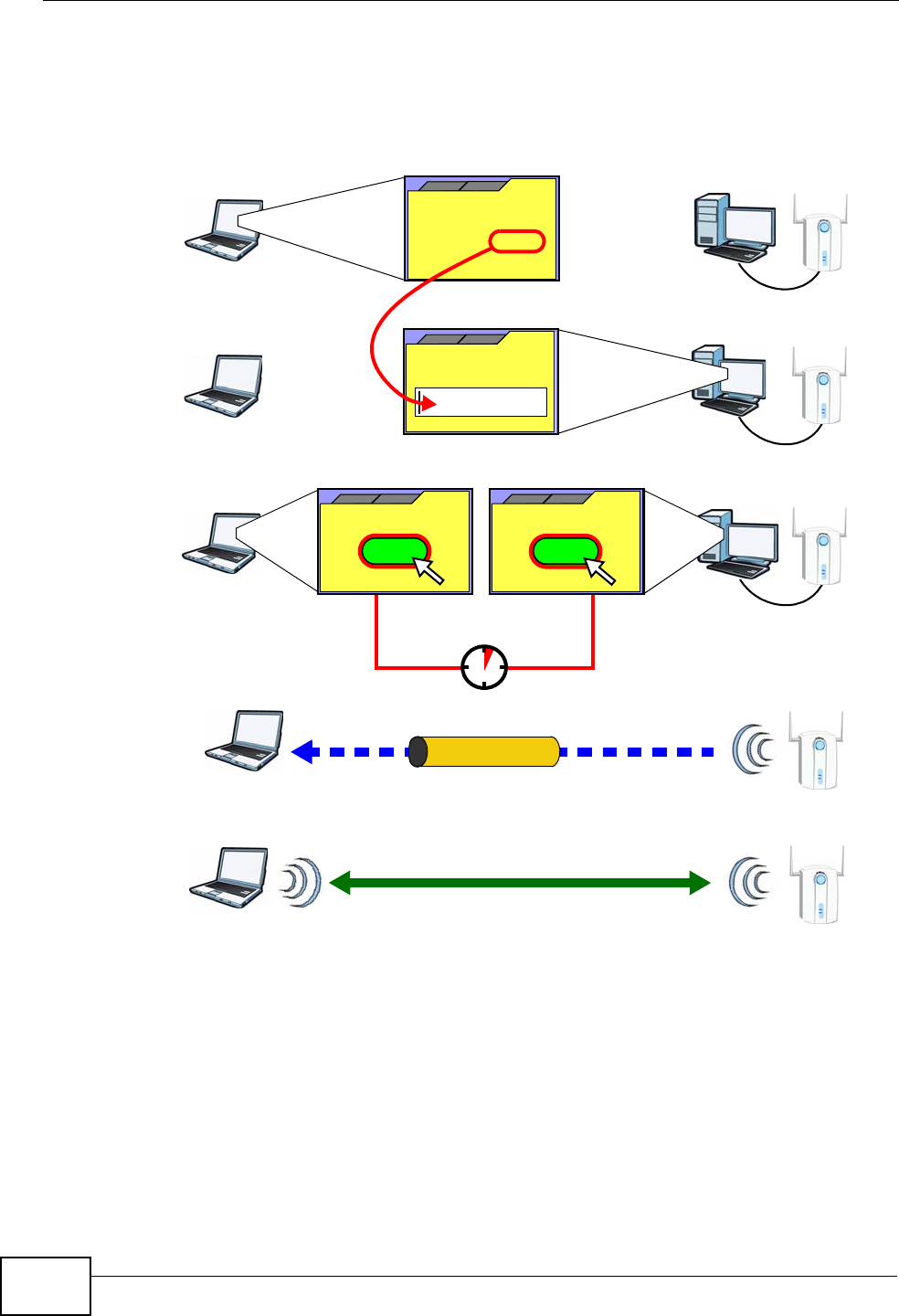
Chapter 8 Wireless LAN
NVG2053 User’s Guide
116
The following figure shows a WPS-enabled wireless client (installed in a notebook
computer) connecting to the WPS-enabled AP via the PIN method.
Figure 44 Example WPS Process: PIN Method
8.10.3.3 How WPS Works
When two WPS-enabled devices connect, each device must assume a specific role.
One device acts as the registrar (the device that supplies network and security
settings) and the other device acts as the enrollee (the device that receives
network and security settings. The registrar creates a secure EAP (Extensible
Authentication Protocol) tunnel and sends the network name (SSID) and the WPA-
PSK or WPA2-PSK pre-shared key to the enrollee. Whether WPA-PSK or WPA2-PSK
is used depends on the standards supported by the devices. If the registrar is
already part of a network, it sends the existing information. If not, it generates
the SSID and WPA(2)-PSK randomly.
ENROLLEE
SECURE EAP TUNNEL
SSID
WPA(2)-PSK
WITHIN 2 MINUTES
COMMUNICATION
This device’s
WPS
Enter WPS PIN
WPS
from other device:
WPS PIN: 123456
WPS
START
WPS
START
REGISTRAR
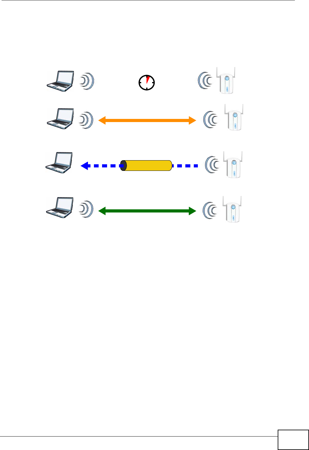
Chapter 8 Wireless LAN
NVG2053 User’s Guide 117
The following figure shows a WPS-enabled client (installed in a notebook
computer) connecting to a WPS-enabled access point.
Figure 45 How WPS works
The roles of registrar and enrollee last only as long as the WPS setup process is
active (two minutes). The next time you use WPS, a different device can be the
registrar if necessary.
The WPS connection process is like a handshake; only two devices participate in
each WPS transaction. If you want to add more devices you should repeat the
process with one of the existing networked devices and the new device.
Note that the access point (AP) is not always the registrar, and the wireless client
is not always the enrollee. All WPS-certified APs can be a registrar, and so can
some WPS-enabled wireless clients.
By default, a WPS devices is “unconfigured”. This means that it is not part of an
existing network and can act as either enrollee or registrar (if it supports both
functions). If the registrar is unconfigured, the security settings it transmits to the
enrollee are randomly-generated. Once a WPS-enabled device has connected to
another device using WPS, it becomes “configured”. A configured wireless client
can still act as enrollee or registrar in subsequent WPS connections, but a
configured access point can no longer act as enrollee. It will be the registrar in all
subsequent WPS connections in which it is involved. If you want a configured AP to
act as an enrollee, you must reset it to its factory defaults.
SECURE TUNNEL
SECURITY INFO
WITHIN 2 MINUTES
COMMUNICATION
ACTIVATE
WPS
ACTIVATE
WPS
WPS HANDSHAKE
REGISTRAR
ENROLLEE
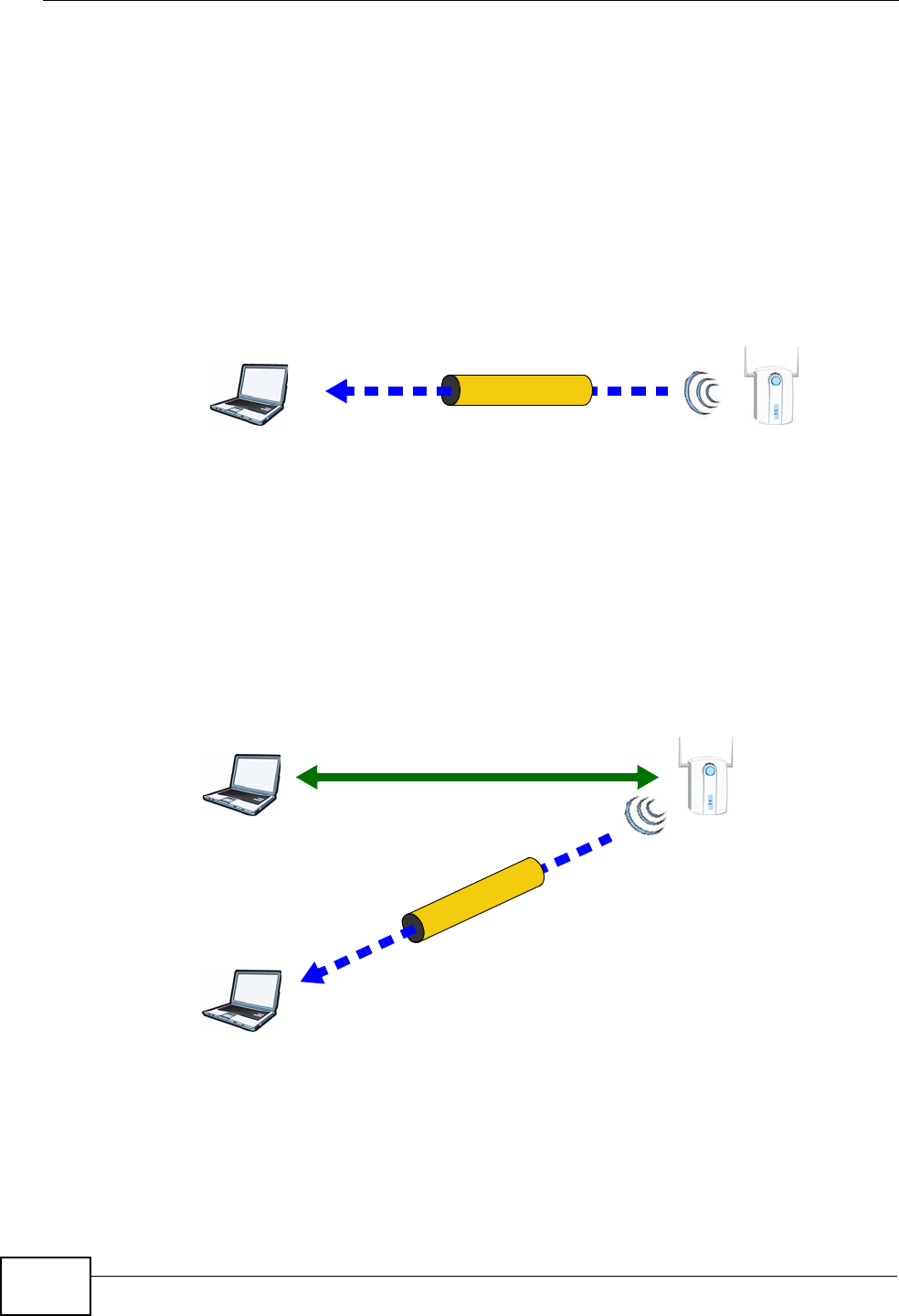
Chapter 8 Wireless LAN
NVG2053 User’s Guide
118
8.10.3.4 Example WPS Network Setup
This section shows how security settings are distributed in an example WPS setup.
The following figure shows an example network. In step 1, both AP1 and Client 1
are unconfigured. When WPS is activated on both, they perform the handshake. In
this example, AP1 is the registrar, and Client 1 is the enrollee. The registrar
randomly generates the security information to set up the network, since it is
unconfigured and has no existing information.
Figure 46 WPS: Example Network Step 1
In step 2, you add another wireless client to the network. You know that Client 1
supports registrar mode, but it is better to use AP1 for the WPS handshake with
the new client since you must connect to the access point anyway in order to use
the network. In this case, AP1 must be the registrar, since it is configured (it
already has security information for the network). AP1 supplies the existing
security information to Client 2.
Figure 47 WPS: Example Network Step 2
In step 3, you add another access point (AP2) to your network. AP2 is out of
range of AP1, so you cannot use AP1 for the WPS handshake with the new access
REGISTRARENROLLEE
SECURITY INFO
CLIENT 1 AP1
REGISTRAR
CLIENT 1 AP1
ENROLLEE
CLIENT 2
EXISTING CONNECTION
SECURITY INFO
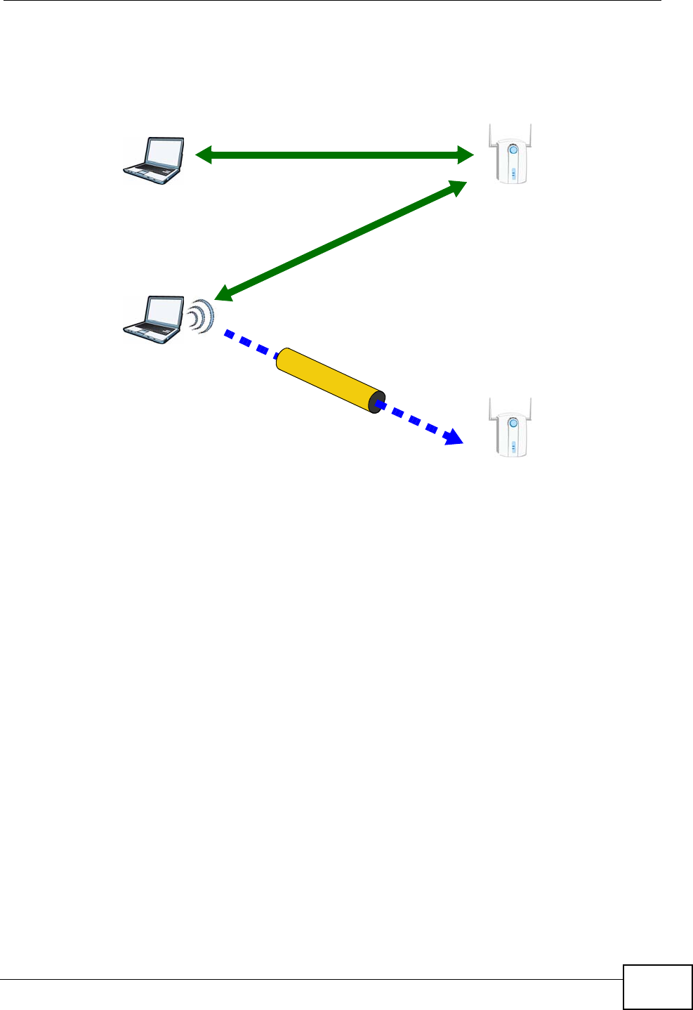
Chapter 8 Wireless LAN
NVG2053 User’s Guide 119
point. However, you know that Client 2 supports the registrar function, so you use
it to perform the WPS handshake instead.
Figure 48 WPS: Example Network Step 3
8.10.3.5 Limitations of WPS
WPS has some limitations of which you should be aware.
• WPS works in Infrastructure networks only (where an AP and a wireless client
communicate). It does not work in Ad-Hoc networks (where there is no AP).
• When you use WPS, it works between two devices only. You cannot enroll
multiple devices simultaneously, you must enroll one after the other.
For instance, if you have two enrollees and one registrar you must set up the
first enrollee (by pressing the WPS button on the registrar and the first enrollee,
for example), then check that it successfully enrolled, then set up the second
device in the same way.
• WPS works only with other WPS-enabled devices. However, you can still add
non-WPS devices to a network you already set up using WPS.
WPS works by automatically issuing a randomly-generated WPA-PSK or WPA2-
PSK pre-shared key from the registrar device to the enrollee devices. Whether
the network uses WPA-PSK or WPA2-PSK depends on the device. You can check
the configuration interface of the registrar device to discover the key the
network is using (if the device supports this feature). Then, you can enter the
key into the non-WPS device and join the network as normal (the non-WPS
device must also support WPA-PSK or WPA2-PSK).
CLIENT 1 AP1
REGISTRAR
CLIENT 2
EXISTING CONNECTION
SECURITY INFO
ENROLLEE
AP2
EXISTING CONNECTION

Chapter 8 Wireless LAN
NVG2053 User’s Guide
120
• When you use the PBC method, there is a short period (from the moment you
press the button on one device to the moment you press the button on the
other device) when any WPS-enabled device could join the network. This is
because the registrar has no way of identifying the “correct” enrollee, and
cannot differentiate between your enrollee and a rogue device. This is a possible
way for a hacker to gain access to a network.
You can easily check to see if this has happened. WPS works between only two
devices simultaneously, so if another device has enrolled your device will be
unable to enroll, and will not have access to the network. If this happens, open
the access point’s configuration interface and look at the list of associated
clients (usually displayed by MAC address). It does not matter if the access
point is the WPS registrar, the enrollee, or was not involved in the WPS
handshake; a rogue device must still associate with the access point to gain
access to the network. Check the MAC addresses of your wireless clients
(usually printed on a label on the bottom of the device). If there is an unknown
MAC address you can remove it or reset the AP.
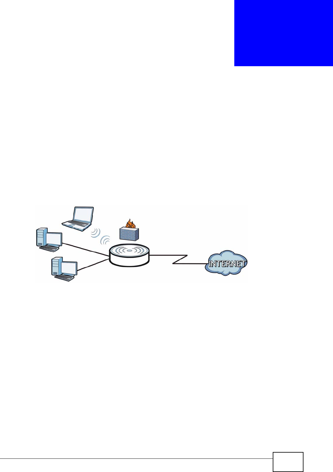
NVG2053 User’s Guide 121
CHAPTER 9
LAN
9.1 Overview
This chapter describes how to configure LAN settings.
A Local Area Network (LAN) is a shared communication system to which many
computers are attached. A LAN is a computer network limited to the immediate
area, usually the same building or floor of a building.
Figure 49 LAN Example
The LAN screens can help you manage IP addresses.
9.2 What You Can Do in this Chapter
•Use the IP screen (Section 9.4 on page 123) to change the IP address for your
NVG2053.
•Use the Advanced screen (Section 9.5 on page 124) to enable IP multicasting
on the LAN.
LAN WAN
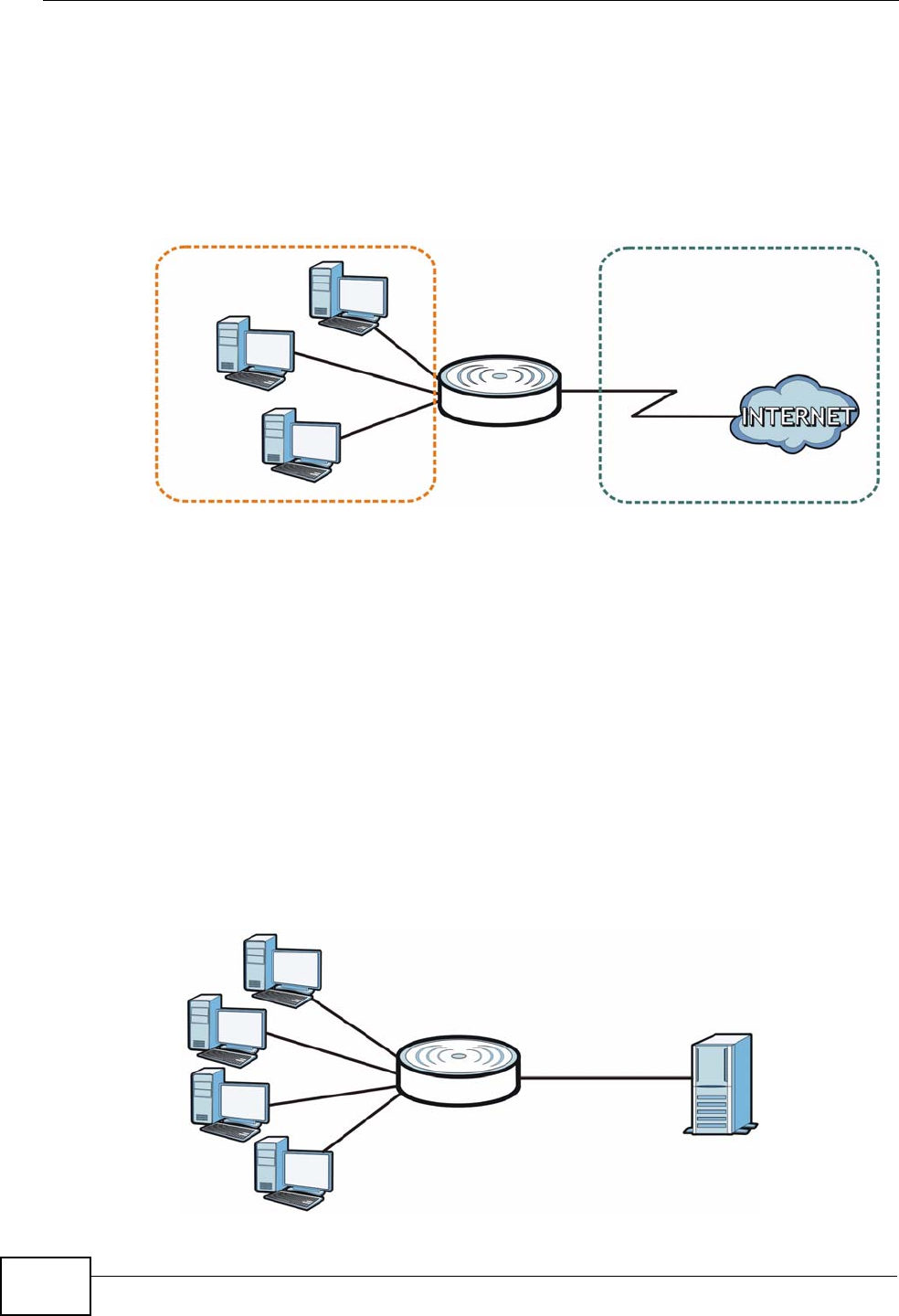
Chapter 9 LAN
NVG2053 User’s Guide
122
9.3 What You Need To Know
The actual physical connection determines whether the NVG2053 ports are LAN or
WAN ports. There are two separate IP networks, one inside the LAN network and
the other outside the WAN network as shown next.
Figure 50 LAN and WAN IP Addresses
The LAN parameters of the NVG2053 are preset in the factory with the following
values:
• IP address of 192.168.1.1 with subnet mask of 255.255.255.0 (24 bits)
• DHCP server enabled with 100 client IP addresses starting from 192.168.1.100.
These parameters should work for the majority of installations.
9.3.1 Multicast
IP packets are transmitted in one of either two ways - Unicast (1 sender - 1
recipient) or Broadcast (1 sender - everybody on the network). Multicast delivers
IP packets to a group of hosts on the network - not everybody and not just 1.
Figure 51 Multicast Example
LAN WAN
A
B
C
DServer
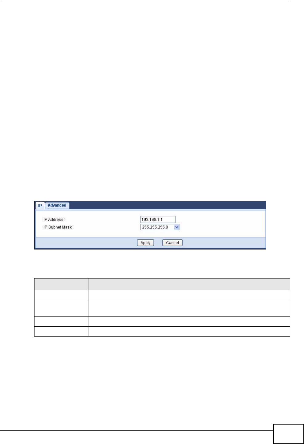
Chapter 9 LAN
NVG2053 User’s Guide 123
In the multicast example above, systems A and D comprise one multicast group.
In multicasting, the server only needs to send one data stream and this is
delivered to systems A and D.
IGMP (Internet Group Multicast Protocol) is a network-layer protocol used to
establish membership in a multicast group - it is not used to carry user data. The
NVG2053 supports both IGMP version 1 (IGMP-v1) and IGMP version 2 (IGMP-
v2).
At start up, the NVG2053 queries all directly connected networks to gather group
membership. After that, the NVG2053 periodically updates this information. IP
multicasting can be enabled/disabled on the NVG2053 LAN and/or WAN interfaces
in the Web Configurator.
9.4 LAN IP Screen
Use this screen to change the IP address for your NVG2053. Click Network >
LAN > IP.
Figure 52 Network > LAN > IP
The following table describes the labels in this screen.
Table 35 Network > LAN > IP
LABEL DESCRIPTION
IP Address Type the IP address of your NVG2053 in dotted decimal notation.
IP Subnet Mask The subnet mask specifies the network number portion of an IP
address. Select a subnet mask from the drop-down list.
Apply Click Apply to save your changes back to the NVG2053.
Cancel Click Cancel to begin configuring this screen afresh.
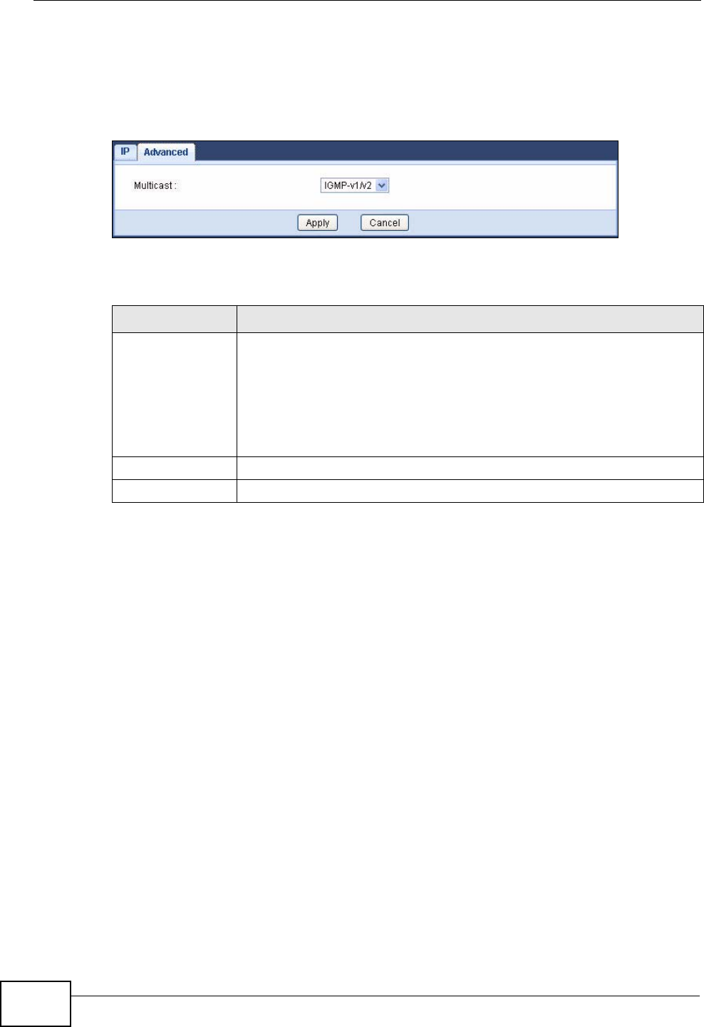
Chapter 9 LAN
NVG2053 User’s Guide
124
9.5 LAN Advanced Screen
Use this screen to edit the NVG2053’s multicast setting. Click LAN > Advanced.
Figure 53 Network > LAN > IP Alias
The following table describes the labels in this screen.
Table 36 Network > LAN > IP Alias
LABEL DESCRIPTION
Multicast IGMP (Internet Group Multicast Protocol) is a network-layer protocol
used to establish membership in a multicast group.
Select IGMPv1/v2 to enable multicasting. This applies to traffic
routed from the WAN to the LAN.
Select None to disable this feature. This may cause incoming traffic to
be dropped or sent to all connected network devices.
Apply Click Apply to save your changes back to the NVG2053.
Cancel Click Cancel to begin configuring this screen afresh.

NVG2053 User’s Guide 125
CHAPTER 10
DHCP Server
10.1 Overview
DHCP (Dynamic Host Configuration Protocol, RFC 2131 and RFC 2132) allows
individual clients to obtain TCP/IP configuration at start-up from a server. You can
configure the NVG2053’s LAN as a DHCP server or disable it. When configured as a
server, the NVG2053 provides the TCP/IP configuration for the clients. If DHCP
service is disabled, you must have another DHCP server on your LAN, or else the
computer must be manually configured.
10.1.1 What You Can Do in this Chapter
•Use the General (Section 10.3 on page 126) screen to enable the DHCP server.
•Use the Advanced (Section 10.4 on page 126) screen to assign IP addresses on
the LAN to specific individual computers based on their MAC Addresses.
•Use the Client List (Section 10.5 on page 128) screen to view current DHCP
client information of all network clients using the NVG2053’s DHCP server.
10.2 What You Need to Know
10.2.1 DHCP
DHCP (Dynamic Host Configuration Protocol) allows clients to obtain TCP/IP
configuration at start-up from a server. The NVG2053 has built-in DHCP server
capability that assigns IP addresses and DNS servers to systems that support
DHCP client capability.
10.2.2 IP Pool Setup
The NVG2053 is pre-configured with a pool of 32 IP addresses starting from
192.168.1.33 to 192.168.1.64. This configuration leaves 31 IP addresses
(excluding the NVG2053 itself) in the lower range (192.168.1.2 to 192.168.1.32)
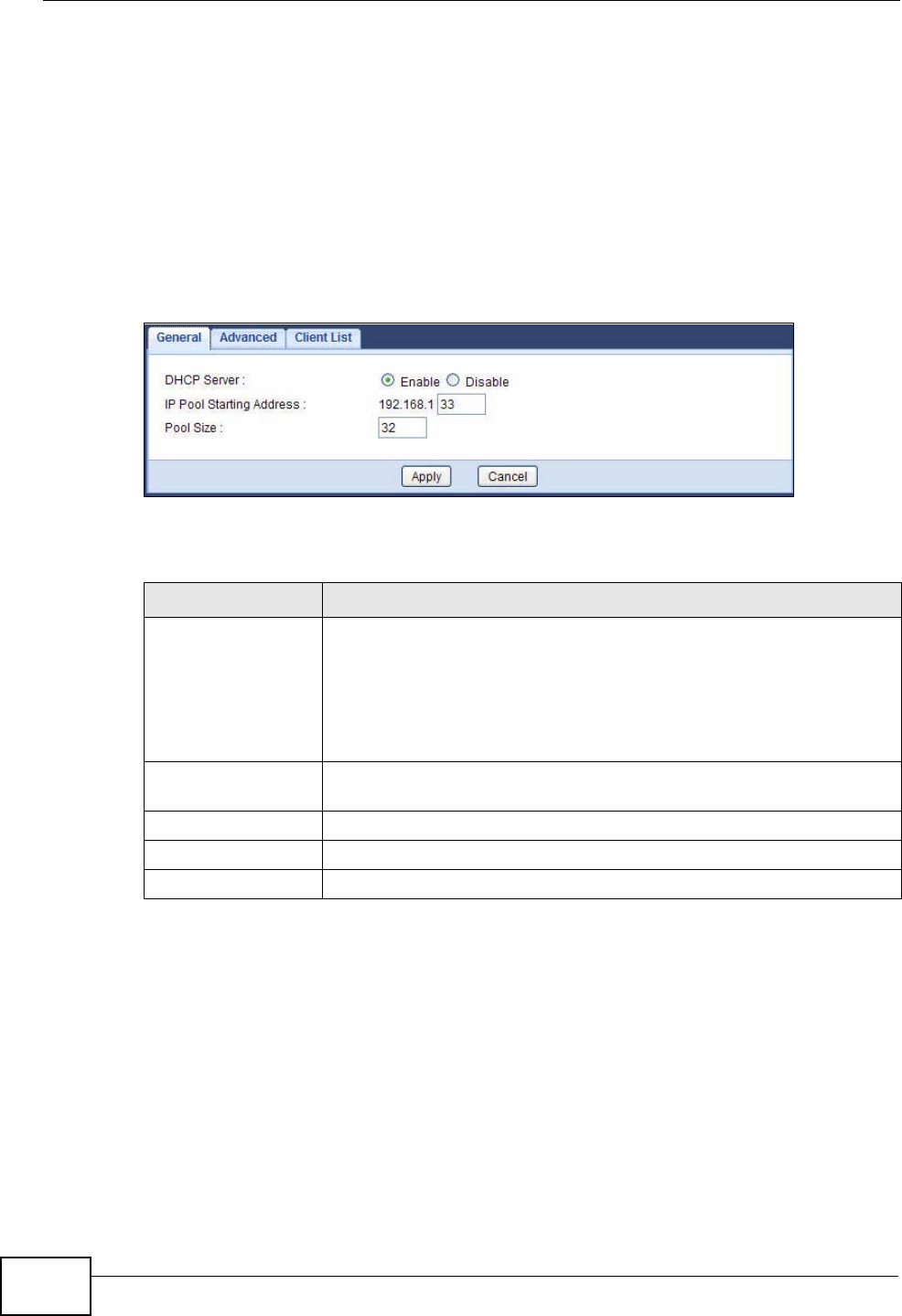
Chapter 10 DHCP Server
NVG2053 User’s Guide
126
for other server computers, for instance, servers for mail, FTP, TFTP, web, etc.,
that you may have.
10.3 General Screen
Use this screen to enable the DHCP server. Click Network > DHCP Server. The
following screen displays.
Figure 54 Network > DHCP Server > General
The following table describes the labels in this screen.
10.4 Advanced Screen
This screen allows you to assign IP addresses on the LAN to specific individual
computers based on their MAC addresses. You can also use this screen to
configure the DNS server information that the NVG2053 sends to the DHCP
clients.
Table 37 Network > DHCP Server > General
LABEL DESCRIPTION
DHCP Server Select Enable to turn on the DHCP server for LAN devices. The
NVG2053 will act as a DHCP server and assign IP addresses and
provide subnet mask, gateway, and DNS server information to the
network.
Otherwise, select Disable to not have the NVG2053 provide any
DHCP services.
IP Pool Starting
Address This field specifies the first of the contiguous addresses in the IP
address pool for LAN.
Pool Size This field specifies the size, or count of the IP address pool for LAN.
Apply Click Apply to save your changes back to the NVG2053.
Cancel Click Cancel to begin configuring this screen afresh.
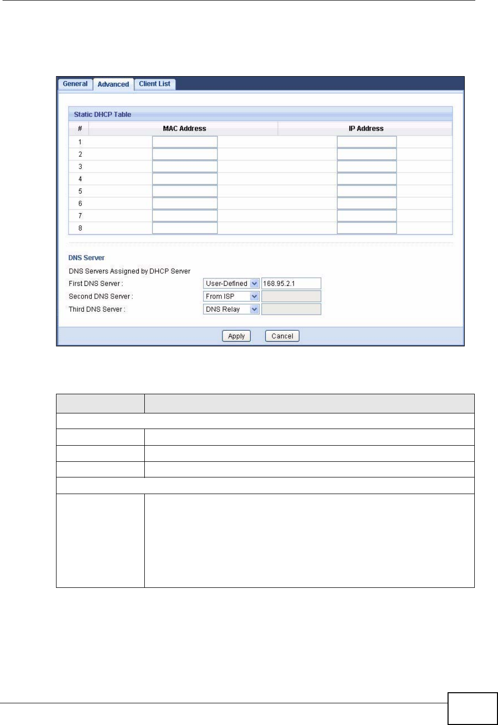
Chapter 10 DHCP Server
NVG2053 User’s Guide 127
To change your NVG2053’s static DHCP settings, click Network > DHCP Server
> Advanced. The following screen displays.
Figure 55 Network > DHCP Server > Advanced
The following table describes the labels in this screen.
Table 38 Network > DHCP Server > Advanced
LABEL DESCRIPTION
Static DHCP Table
# This is the index number of the static IP table entry (row).
MAC Address Type the MAC address (with colons) of a computer on your LAN.
IP Address Type the LAN IP address of a computer on your LAN.
DNS Server
DNS Servers
Assigned by
DHCP Server
The NVG2053 passes a DNS (Domain Name System) server IP
address (in the order you specify here) to the DHCP clients. The
NVG2053 only passes this information to the LAN DHCP clients when
you enable the DHCP Server on the NVG2053. When you set DHCP
Server to Disable in the DHCP Server > General screen, DHCP
service is disabled and you must have another DHCP sever on your
LAN, or else the computers must have their DNS server addresses
manually configured.
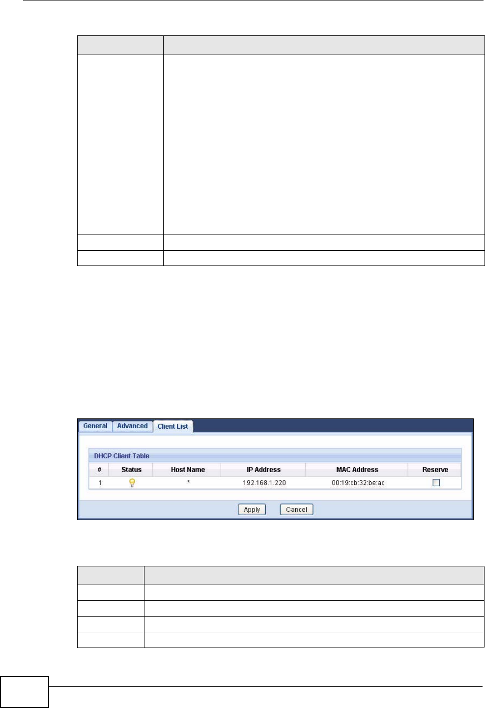
Chapter 10 DHCP Server
NVG2053 User’s Guide
128
10.5 Client List Screen
Click Network > DHCP Server > Client List. Read-only information here relates
to your DHCP status. The DHCP table shows current DHCP client information
(including IP Address, Host Name and MAC Address) of all network clients
using the NVG2053’s DHCP server.
Figure 56 Network > DHCP Server > Client List
The following table describes the labels in this screen.
First DNS Server
Second DNS
Server
Third DNS Server
Select From ISP if your ISP dynamically assigns DNS server
information (and the NVG2053's WAN IP address).
Select User-Defined if you have the IP address of a DNS server.
Enter the DNS server's IP address in the field to the right.
Select DNS Relay to have the NVG2053 act as a DNS proxy. The
NVG2053's LAN IP address displays in the field to the right (read-
only). The NVG2053 tells the DHCP clients on the LAN that the
NVG2053 itself is the DNS server. When a computer on the LAN sends
a DNS query to the NVG2053, the NVG2053 forwards the query to the
NVG2053's system DNS server (configured in the Network >
Broadband screen) and relays the response back to the computer.
Select None if you do not want to configure DNS servers. If you do
not configure a DNS server, you must know the IP address of a
computer in order to access it.
Apply Click Apply to save your changes back to the NVG2053.
Cancel Click Cancel to begin configuring this screen afresh.
Table 38 Network > DHCP Server > Advanced
LABEL DESCRIPTION
Table 39 Network > DHCP Server > Client List
LABEL DESCRIPTION
# This is the index number of the host computer.
Status This displays whether the client is connected to the NVG2053.
Host Name This indicates the computer host name.
IP Address This indicates the IP address assigned to this client computer.

Chapter 10 DHCP Server
NVG2053 User’s Guide 129
MAC Address This field shows the MAC address of the client computer.
Every Ethernet device has a unique MAC (Media Access Control) address
which uniquely identifies a device. The MAC address is assigned at the
factory and consists of six pairs of hexadecimal characters, for example,
00:A0:C5:00:00:02.
Reserve Select the check box(es) in each entry to have the NVG2053 always assign
the selected entry(ies)’s IP address(es) to the corresponding MAC
address(es) (and host name(s)).
After you click Apply, the MAC address and IP address also display in the
DHCP Server > Advanced screen (where you can edit them).
Table 39 Network > DHCP Server > Client List (continued)
LABEL DESCRIPTION

Chapter 10 DHCP Server
NVG2053 User’s Guide
130

NVG2053 User’s Guide 131
CHAPTER 11
Quality of Service (QoS)
11.1 Overview
Quality of Service (QoS) refers to both a network’s ability to deliver data with
minimum delay, and the networking methods used to control the use of
bandwidth. Without QoS, all traffic data is equally likely to be dropped when the
network is congested. This can cause a reduction in network performance and
make the network inadequate for time-critical application such as video-on-
demand.
Configure QoS on the NVG2053 to group and prioritize application traffic and fine-
tune network performance. Setting up QoS involves these steps:
1Configure classifiers to sort traffic into different flows.
2Assign priority and define actions to be performed for a classified traffic flow.
The NVG2053 assigns each packet a priority and then queues the packet
accordingly. Packets assigned a high priority are processed more quickly than
those with low priority if there is congestion, allowing time-sensitive applications
to flow more smoothly. Time-sensitive applications include both those that require
a low level of latency (delay) and a low level of jitter (variations in delay) such as
Voice over IP (VoIP) or Internet gaming, and those for which jitter alone is a
problem such as Internet radio or streaming video.
This chapter contains information about configuring QoS and editing classifiers.
11.1.1 What You Can Do in this Chapter
Use the General (Section 11.2 on page 132) screen to enable or disable QoS, set
the bandwidth, and allow the NVG2053 to automatically assign priority to upstream
traffic according to the DSCP value. This screen also lets you add, edit or delete
QoS classes.
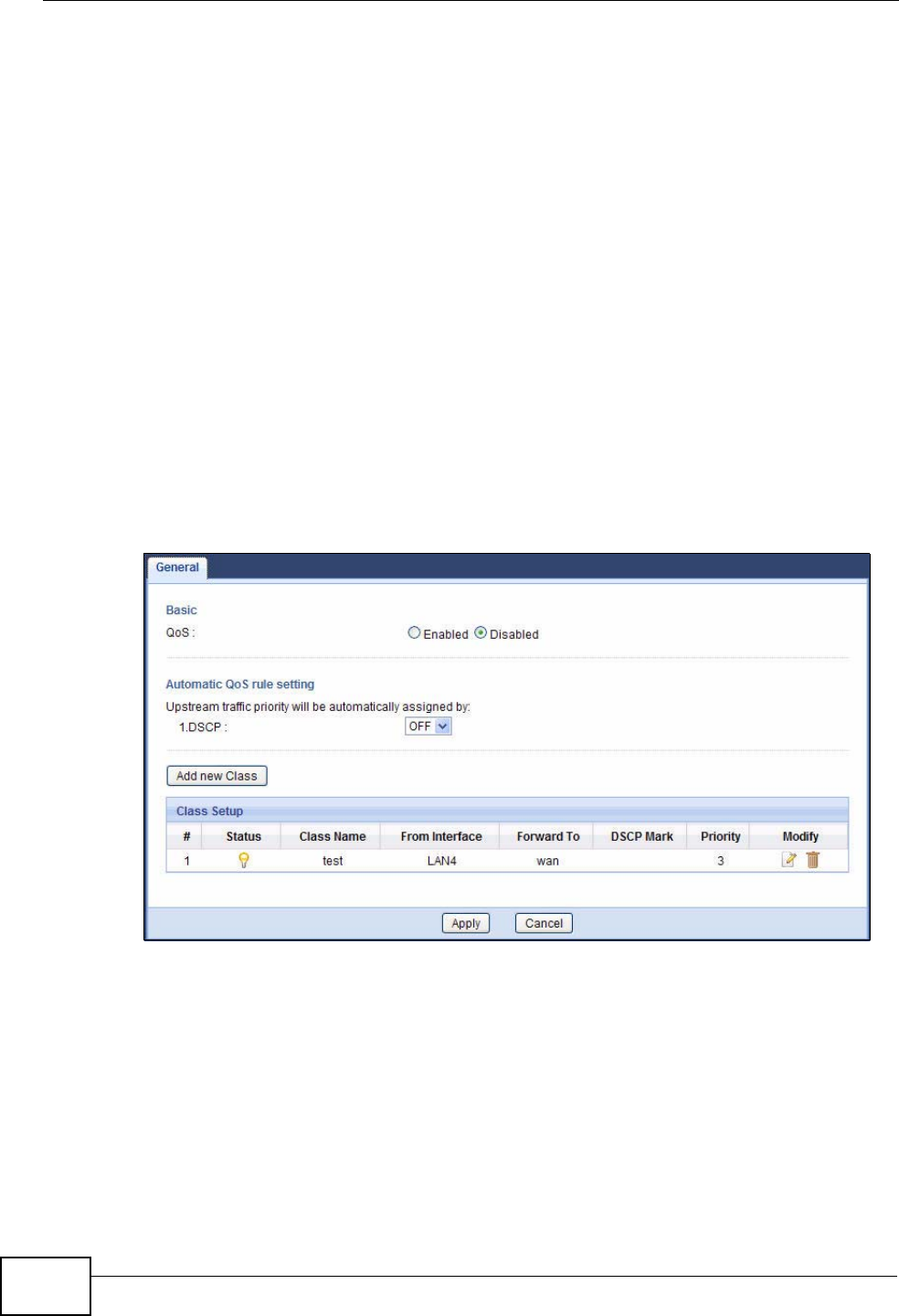
Chapter 11 Quality of Service (QoS)
NVG2053 User’s Guide
132
11.2 The Quality of Service General Screen
Click Configuration > Network > QoS to open the screen as shown next.
Use this screen to enable or disable QoS, set the bandwidth, and select to have
the NVG2053 automatically assign priority to upstream traffic according to the
DSCP value in the packets. See Section 11.1 on page 131 for more information.
You can also use this screen to add, edit or delete QoS classes. A class groups
traffic into data flows according to specific criteria such as the source address,
destination address, source port number, destination port number or incoming
interface. For example, you can configure a class to select traffic from the same
protocol port (such as Telnet) to form a flow.
You can give different priorities to traffic that the NVG2053 forwards out through a
WAN interface. Give high priority to voice and video to make them run more
smoothly. Similarly, give low priority to many large file downloads so that they do
not reduce the quality of other applications.
Figure 57 QoS General

Chapter 11 Quality of Service (QoS)
NVG2053 User’s Guide 133
The following table describes the labels in this screen.
Table 40 QoS General
LABEL DESCRIPTION
QoS Select Enabled to turn on QoS to improve your network performance.
Otherwise, select Disabled.
Upstream
traffic priority
will be
automatically
assigned by
These fields are ignored if upstream traffic matches a pre-configured
QoS class.
If you select ON and traffic does not match a a pre-configured QoS
class, the NVG2053 assigns priority to unmatched traffic based on the
DSCP value in the packets. See Section 11.3 on page 135 for more
information.
If you select OFF, traffic which does not match a class is mapped to the
default queue with the lowest priority.
Add new Class Click this button to create a new QoS class.
#This field displays the index number of the class.
Status This shows whether the class is enabled or not.
Class Name This is the name of the classifier.
From Interface This is the interface from which traffic of this class should come.
Forward To This is the interface through which traffic that matches this class is
forwarded out.
DSCP Mark This is the DSCP number added to traffic of this class.
Priority This is the priority level assigned to traffic of this class.
Modify Click the Edit icon to go to the screen where you can edit the classifier.
Click the Remove icon to delete an existing classifier. Note that
subsequent rules move up by one when you take this action.
Apply Click Apply to save your changes back to the NVG2053.
Cancel Click Cancel to begin configuring this screen afresh.
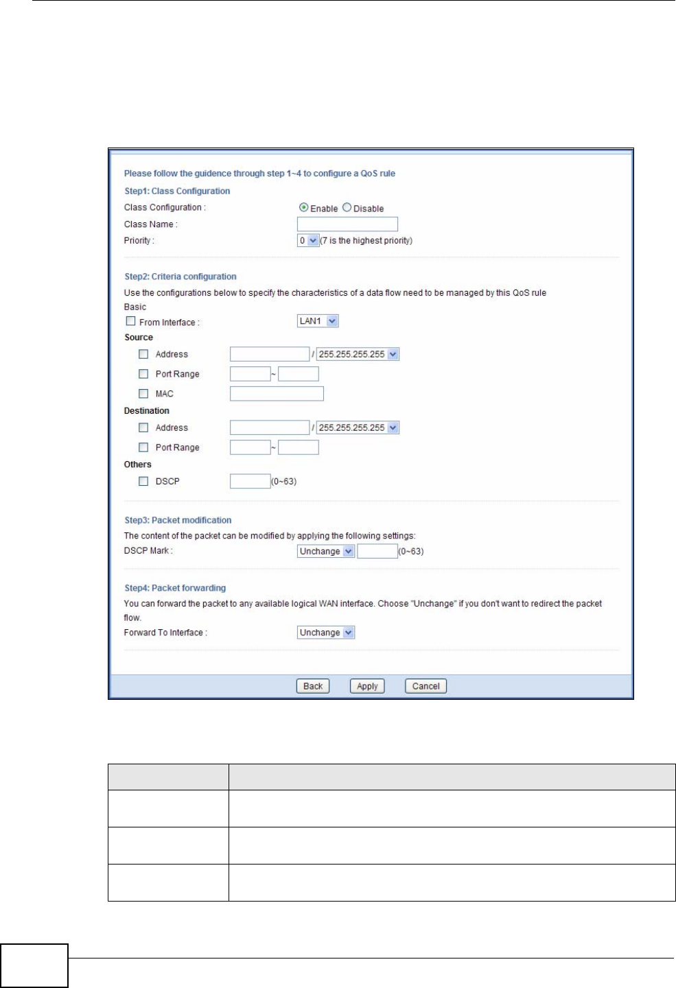
Chapter 11 Quality of Service (QoS)
NVG2053 User’s Guide
134
11.2.1 QoS Class Edit
Click the Add new Class button or the Edit icon in the QoS > General screen to
configure a classifier.
Figure 58 QoS Class Configuration
The following table describes the labels in this screen.
Table 41 QoS Class Configuration
LABEL DESCRIPTION
Class
Configuration Select to enable or disable this class.
Class Name Enter a descriptive name of up to 20 printable English keyboard
characters, including spaces.
Priority Select a priority level (between 0 and 7) from the drop down list box.
"7" is the highest priority level and "0" is the lowest.

Chapter 11 Quality of Service (QoS)
NVG2053 User’s Guide 135
11.3 Technical Reference
The following section contains additional technical information about the NVG2053
features described in this chapter.
QoS versus Cos
QoS is used to prioritize source-to-destination traffic flows. All packets in the same
flow are given the same priority. CoS (class of service) is a way of managing traffic
Criteria Configuration
Use the following fields to configure the criteria for traffic classification.
From Interface Select from which LAN, WLAN or FXS interface traffic of this class
should come.
Source
Address Select the check box and enter the source IP address in dotted
decimal notation and select a source subnet mask.
Port Range Select the check box and enter the port number(s) of the source.
MAC Select the check box and enter the source MAC address of the packet.
Destination
IP Address Select the check box and enter the destination IP address in dotted
decimal notation and select a source subnet mask.
Port Range Select the check box and enter the port number(s) of the source.
Others
DSCP Select this option and specify a DSCP (DiffServ Code Point) number
between 0 and 63 in the field provided.
Packet
modification
DSCP Mark If you select Mark, enter a DSCP value with which the NVG2053
replaces the DSCP field in the packets.
If you select Unchange, the NVG2053 keep the DSCP field in the
packets.
Packet
forwarding
Forward to
Interface Select a WAN interface through which traffic of this class will be
forwarded out. If you select Unchange, the NVG2053 forward traffic
of this class according to the default routing table.
Back Click Back to return to the previous screen without saving.
Apply Click Apply to save your changes back to the NVG2053.
Cancel Click Cancel to begin configuring this screen afresh.
Table 41 QoS Class Configuration (continued)
LABEL DESCRIPTION
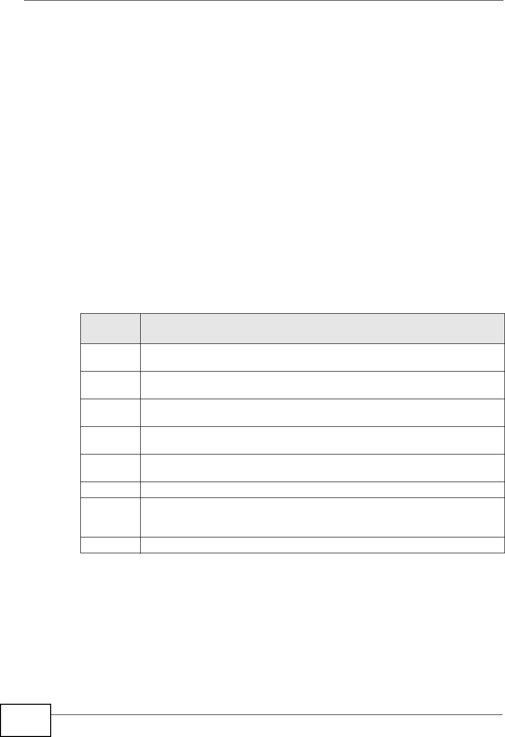
Chapter 11 Quality of Service (QoS)
NVG2053 User’s Guide
136
in a network by grouping similar types of traffic together and treating each type as
a class. You can use CoS to give different priorities to different packet types.
CoS technologies include IEEE 802.1p layer 2 tagging and DiffServ (Differentiated
Services or DS). IEEE 802.1p tagging makes use of three bits in the packet
header, while DiffServ is a new protocol and defines a new DS field, which replaces
the eight-bit ToS (Type of Service) field in the IP header.
IEEE 802.1Q Tag
The IEEE 802.1Q standard defines an explicit VLAN tag in the MAC header to
identify the VLAN membership of a frame across bridges. A VLAN tag includes the
12-bit VLAN ID and 3-bit user priority. The VLAN ID associates a frame with a
specific VLAN and provides the information that devices need to process the frame
across the network.
IEEE 802.1p specifies the user priority field and defines up to eight separate traffic
types. The following table describes the traffic types defined in the IEEE 802.1d
standard (which incorporates the 802.1p).
DiffServ
QoS is used to prioritize source-to-destination traffic flows. All packets in the flow
are given the same priority. You can use CoS (class of service) to give different
priorities to different packet types.
DiffServ (Differentiated Services) is a class of service (CoS) model that marks
packets so that they receive specific per-hop treatment at DiffServ-compliant
Table 42 IEEE 802.1p Priority Level and Traffic Type
PRIORITY
LEVEL TRAFFIC TYPE
Level 7 Typically used for network control traffic such as router configuration
messages.
Level 6 Typically used for voice traffic that is especially sensitive to jitter (jitter is the
variations in delay).
Level 5 Typically used for video that consumes high bandwidth and is sensitive to
jitter.
Level 4 Typically used for controlled load, latency-sensitive traffic such as SNA
(Systems Network Architecture) transactions.
Level 3 Typically used for “excellent effort” or better than best effort and would
include important business traffic that can tolerate some delay.
Level 2 This is for “spare bandwidth”.
Level 1 This is typically used for non-critical “background” traffic such as bulk
transfers that are allowed but that should not affect other applications and
users.
Level 0 Typically used for best-effort traffic.

Chapter 11 Quality of Service (QoS)
NVG2053 User’s Guide 137
network devices along the route based on the application types and traffic flow.
Packets are marked with DiffServ Code Points (DSCPs) indicating the level of
service desired. This allows the intermediary DiffServ-compliant network devices
to handle the packets differently depending on the code points without the need to
negotiate paths or remember state information for every flow. In addition,
applications do not have to request a particular service or give advanced notice of
where the traffic is going.
DSCP and Per-Hop Behavior
DiffServ defines a new Differentiated Services (DS) field to replace the Type of
Service (TOS) field in the IP header. The DS field contains a 2-bit unused field and
a 6-bit DSCP field which can define up to 64 service levels. The following figure
illustrates the DS field.
DSCP is backward compatible with the three precedence bits in the ToS octet so
that non-DiffServ compliant, ToS-enabled network device will not conflict with the
DSCP mapping.
The DSCP value determines the forwarding behavior, the PHB (Per-Hop Behavior),
that each packet gets across the DiffServ network. Based on the marking rule,
different kinds of traffic can be marked for different kinds of forwarding. Resources
can then be allocated according to the DSCP values and the configured policies.
IP Precedence
Similar to IEEE 802.1p prioritization at layer-2, you can use IP precedence to
prioritize packets in a layer-3 network. IP precedence uses three bits of the eight-
bit ToS (Type of Service) field in the IP header. There are eight classes of services
(ranging from zero to seven) in IP precedence. Zero is the lowest priority level and
seven is the highest.
Automatic Priority Queue Assignment
If you enable QoS on the NVG2053, the NVG2053 can automatically base on the
IEEE 802.1p priority level, IP precedence and/or packet length to assign priority to
traffic which does not match a class.
The following table shows you the internal layer-2 and layer-3 QoS mapping on
the NVG2053. On the NVG2053, traffic assigned to higher priority queues gets
DSCP (6 bits) Unused (2 bits)

Chapter 11 Quality of Service (QoS)
NVG2053 User’s Guide
138
through faster while traffic in lower index queues is dropped if the network is
congested.
Table 43 Internal Layer2 and Layer3 QoS Mapping
PRIORITY
QUEUE
LAYER 2 LAYER 3
IEEE 802.1P
USER PRIORITY
(ETHERNET
PRIORITY)
TOS (IP
PRECEDENCE) DSCP IP PACKET
LENGTH (BYTE)
0 1 0 000000
12
2 0 0 000000 >1100
3 3 1 001110
001100
001010
001000
250~1100
4 4 2 010110
010100
010010
010000
5 5 3 011110
011100
011010
011000
<250
6 6 4 100110
100100
100010
100000
5 101110
101000
7 7 6 110000
111000
7
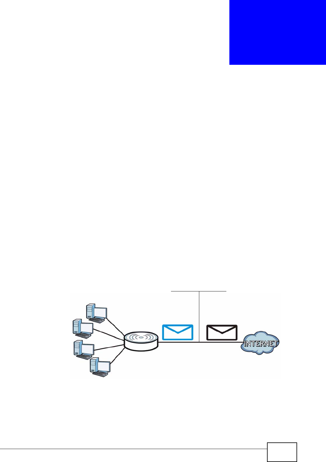
NVG2053 User’s Guide 139
CHAPTER 12
Network Address Translation
(NAT)
12.1 Overview
NAT (Network Address Translation - NAT, RFC 1631) is the translation of the IP
address of a host in a packet. For example, the source address of an outgoing
packet, used within one network is changed to a different IP address known within
another network.
Each packet has two addresses – a source address and a destination address. For
outgoing packets, NAT maps private (local) IP addresses to globally unique ones
required for communication with hosts on other networks. It replaces the original
IP source address in each packet and then forwards it to the Internet. The
NVG2053 keeps track of the original addresses and port numbers so incoming
reply packets can have their original values restored. The following figure
illustrates this.
Figure 59 NAT Example
For more information on IP address translation, refer to RFC 1631, The IP Network
Address Translator (NAT).
192.168.1.13
192.168.1.12
192.168.1.11
192.168.1.10
192.168.1.10
192.168.1.10
192.168.1.11
192.168.1.12
192.168.1.13
Public IP
NAT Table
LAN WAN
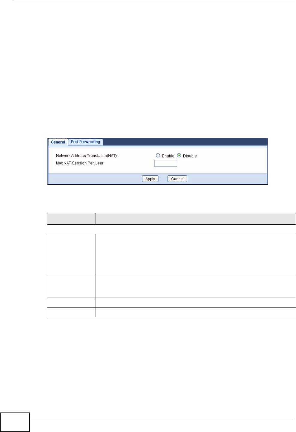
Chapter 12 Network Address Translation (NAT)
NVG2053 User’s Guide
140
12.1.1 What You Can Do in this Chapter
•Use the General screen (Section 12.2 on page 140) to enable NAT and set the
maximum NAT sessions.
•Use the Port Forwarding screen (Section 12.3 on page 140) to forward
incoming service requests to the server(s) on your local network.
12.2 The General NAT Screen
Use this screen to enable NAT. Click Network > NAT > General to open the
following screen.
Figure 60 Network > NAT > General
The following table describes the labels in this screen.
12.3 The NAT Port Forwarding Screen
Use this screen to forward incoming service requests to the server(s) on your local
network and set a default server. You may enter a single port number or a range
of port numbers to be forwarded, and the local IP address of the desired server.
The port number identifies a service; for example, web service is on port 80 and
FTP on port 21. In some cases, such as for unknown services or where one server
Table 44 Network > NAT > General
LABEL DESCRIPTION
NAT Setup
Network
Address
Translation
(NAT)
Network Address Translation (NAT) allows the translation of an Internet
protocol address used within one network (for example a private IP
address used in a local network) to a different IP address known within
another network (for example a public IP address used on the Internet).
Select to enable or disable NAT on the NVG2053.
Max NAT
Session Per
User
Specify the highest number of NAT sessions that the NVG2053 will
permit a host to have at one time.
Apply Click Apply to save your changes back to the NVG2053.
Cancel Click Cancel to begin configuring this screen afresh.
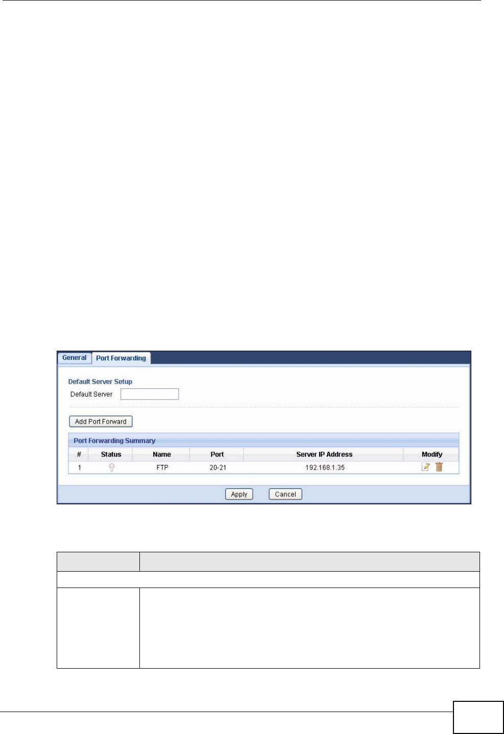
Chapter 12 Network Address Translation (NAT)
NVG2053 User’s Guide 141
can support more than one service (for example both FTP and web service), it
might be better to specify a range of port numbers.
In addition to the servers for specified services, NAT supports a default server. A
service request that does not have a server explicitly designated for it is forwarded
to the default server. If the default is not defined, the service request is simply
discarded.
Note: Many residential broadband ISP accounts do not allow you to run any server
processes (such as a Web or FTP server) from your location. Your ISP may
periodically check for servers and may suspend your account if it discovers any
active services at your location. If you are unsure, refer to your ISP.
Port forwarding allows you to define the local servers to which the incoming
services will be forwarded. To change your NVG2053’s port forwarding settings,
click Network > NAT > Port Forwarding. The screen appears as shown.
Note: If you do not assign a Default Server, the NVG2053 discards all packets
received for ports that are not specified in this screen or remote management.
Refer to Appendix F on page 319 for port numbers commonly used for particular
services.
Figure 61 Network > NAT > Port Forwarding
The following table describes the labels in this screen.
Table 45 Network > NAT > Port Forwarding
LABEL DESCRIPTION
Default Server Setup
Default Server In addition to the servers for specified services, NAT supports a default
server. A default server receives packets from ports that are not
specified in the Port Forwarding screen.
If you do not assign a Default Server IP address, the NVG2053
discards all packets received for ports that are not specified in the Port
Forwarding screen or remote management.
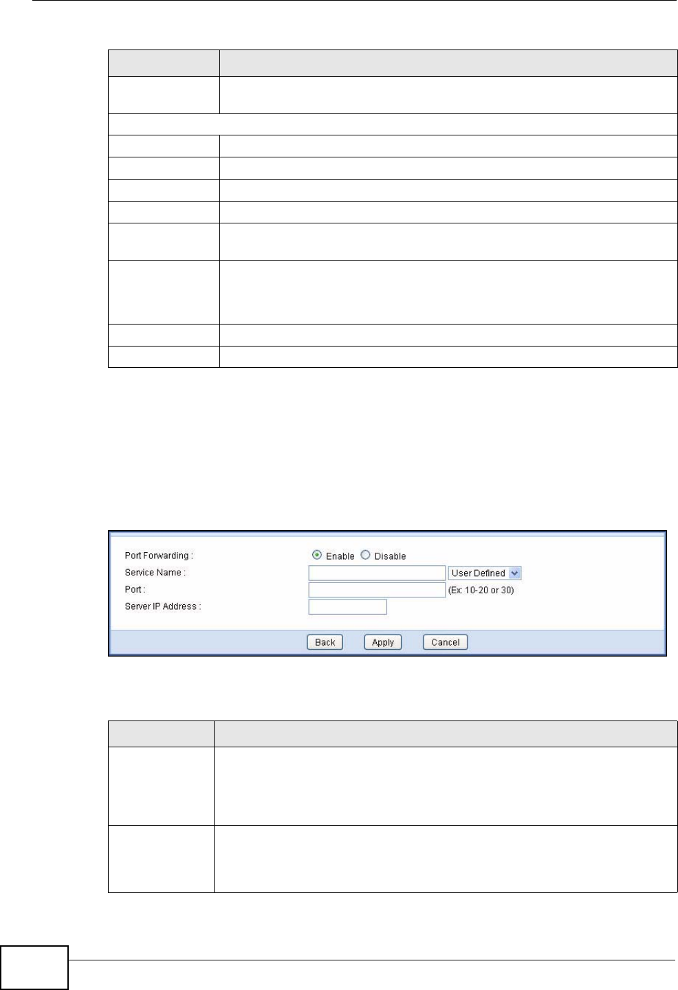
Chapter 12 Network Address Translation (NAT)
NVG2053 User’s Guide
142
12.3.1 Port Forwarding Edit Screen
This screen lets you create or edit a port forwarding rule. Click the Add Port
Forward button or a rule’s Edit icon in the Port Forwarding screen to open the
following screen.
Figure 62 NAT > Port Forwarding Edit
The following table describes the labels in this screen.
Add Port
Forward Click this button to open a screen where you can add a rule to the table
below.
Port Forwarding Summary
#This is the number of an individual port forwarding server entry.
Status This icon is turned on when the rule is enabled.
Name This field displays a name to identify this rule.
Port This field displays the port number(s).
Server IP
Address This field displays the inside IP address of the server.
Modify Click the Edit icon to open a screen where you can modify an existing
rule.
Click the Remove icon to delete a rule.
Apply Click Apply to save your changes back to the NVG2053.
Cancel Click Cancel to begin configuring this screen afresh.
Table 45 Network > NAT > Port Forwarding (continued)
LABEL DESCRIPTION
Table 46 NAT > Port Forwarding Edit
LABEL DESCRIPTION
Port
Forwarding Select Enable to turn on this rule and the requested service can be
forwarded to the host with a specified internal IP address.
Select Disable to disallow forwarding of these ports to an inside server
without having to delete the entry.
Service Name Type a name (of up to 31 printable characters) to identify this rule in the
first field next to Service Name. Otherwise, select a predefined service
in the second field next to Service Name. The predefined service name
and port number(s) will display in the Service Name and Port fields.

Chapter 12 Network Address Translation (NAT)
NVG2053 User’s Guide 143
Port Type a port number(s) to define the service to be forwarded to the
specified server.
To specify a range of ports, enter a hyphen (-) between the first port and
the last port, such as 10-20.
Server IP
Address Type the IP address of the server on your LAN that receives packets from
the port(s) specified in the Port field.
Back Click Back to return to the previous screen.
Apply Click Apply to save your changes back to the NVG2053.
Cancel Click Cancel to begin configuring this screen afresh.
Table 46 NAT > Port Forwarding Edit (continued)
LABEL DESCRIPTION

Chapter 12 Network Address Translation (NAT)
NVG2053 User’s Guide
144

NVG2053 User’s Guide 145
CHAPTER 13
Dynamic DNS
13.1 Overview
Dynamic DNS (DDNS) services let you use a domain name with a dynamic IP
address.
13.1.1 What You Can Do in this Chapter
Use the Dynamic DNS screen (Section 13.3 on page 146) to enable DDNS and
configure the DDNS settings on the NVG2053.
13.2 What You Need To Know
Dynamic DNS allows you to update your current dynamic IP address with one or
many dynamic DNS services so that anyone can contact you (in NetMeeting, CU-
SeeMe, etc.). You can also access your FTP server or Web site on your own
computer using a domain name (for instance myhost.dhs.org, where myhost is a
name of your choice) that will never change instead of using an IP address that
changes each time you reconnect. Your friends or relatives will always be able to
call you even if they don't know your IP address.
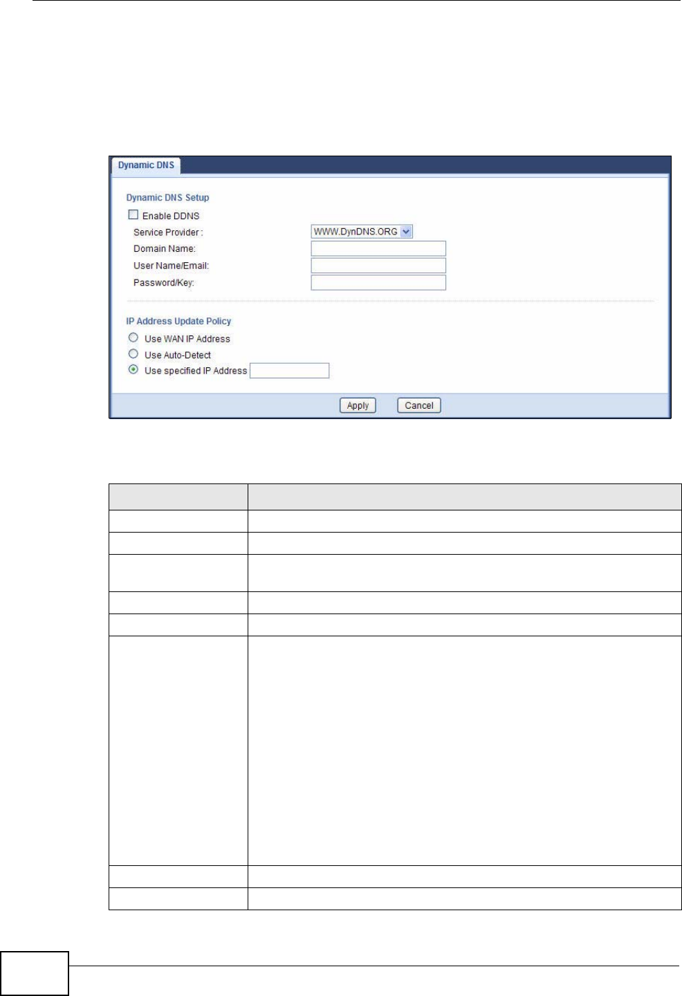
Chapter 13 Dynamic DNS
NVG2053 User’s Guide
146
13.3 The Dynamic DNS Screen
To change your NVG2053’s DDNS, click Network > DDNS. The screen appears as
shown.
Figure 63 Network > DDNS
The following table describes the labels in this screen.
Table 47 Network > DDNS
LABEL DESCRIPTION
Enable DDNS Select this check box to use dynamic DNS.
Service Provider Select the name of your Dynamic DNS service provider.
Domain Name Type the domain name assigned to your NVG2053 by your Dynamic
DNS provider.
User Name/Email Enter the user name you used to register for this service.
Password/Key Enter the password you used to register for this service.
IP Address Update
Policy Select Use WAN IP Address to have the NVG2053 update the
domain name with the WAN interface's IP address.
Select Auto-Detect only when there are one or more NAT routers
between the NVG2053 and the DDNS server. This feature has the
DDNS server automatically detect and use the IP address of the
NAT router that has a public IP address.
Note: The DDNS server may not be able to detect the proper IP
address if there is an HTTP proxy server between the
NVG2053 and the DDNS server.
Select Use specified IP Address and enter the IP address if you
have a static IP address.
Apply Click Apply to save your changes back to the NVG2053.
Cancel Click Cancel to begin configuring this screen afresh.
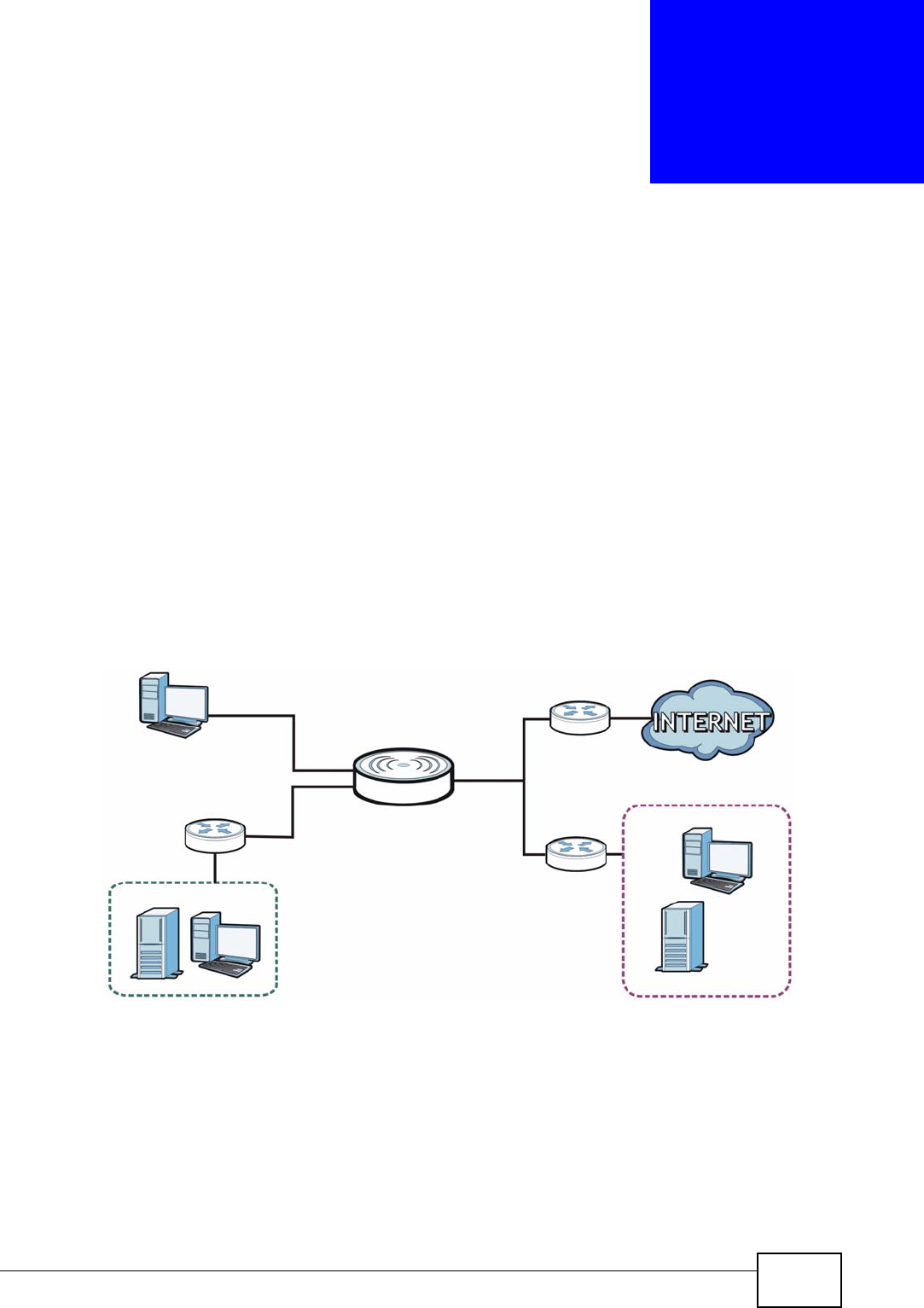
NVG2053 User’s Guide 147
CHAPTER 14
Static Route
14.1 Overview
The NVG2053 usually uses the default gateway to route outbound traffic from
computers on the LAN to the Internet. To have the NVG2053 send data to devices
not reachable through the default gateway, use static routes.
For example, the next figure shows a computer (A) connected to the NVG2053’s
LAN interface. The NVG2053 routes most traffic from A to the Internet through
the NVG2053’s default gateway (R1). You create one static route to connect to
services offered by your ISP behind router R2. You create another static route to
communicate with a separate network behind a router R3 connected to the LAN.
Figure 64 Example of Static Routing Topology
14.1.1 What You Can Do in this Chapter
Use the Static Route screen (Section 14.2 on page 148) to view, add and delete
static routes on the NVG2053.
AR1
R2
R3
LAN WAN
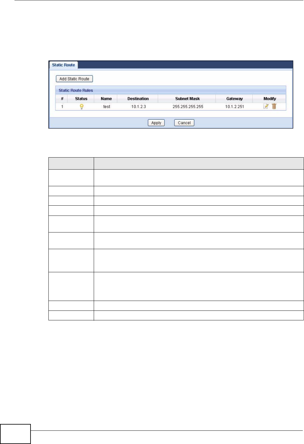
Chapter 14 Static Route
NVG2053 User’s Guide
148
14.2 The IP Static Route Screen
Click Network > Static Route to open the IP Static Route screen.
Figure 65 Network > Static Route
The following table describes the labels in this screen.
Table 48 Advanced > Static Route
LABEL DESCRIPTION
Add Static
Route Click this to create a new rule.
#This is the number of an individual static route.
Status This field indicates whether the rule is active or not.
Name This field displays a name to identify this rule.
Destination This parameter specifies the IP network address of the final destination.
Routing is always based on network number.
Subent Mask This parameter specifies the IP network subnet mask of the final
destination.
Gateway This is the IP address of the gateway. The gateway is a router or switch
on the same network segment as the device's LAN or WAN port. The
gateway helps forward packets to their destinations.
Modify Click the Edit icon to open a screen where you can modify an existing
rule.
Click the Remove icon to delete a rule from the NVG2053.
Apply Click Apply to save your changes back to the NVG2053.
Cancel Click Cancel to begin configuring this screen afresh.
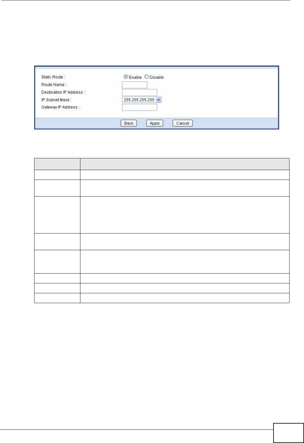
Chapter 14 Static Route
NVG2053 User’s Guide 149
14.2.1 Static Route Edit
Click the Add Static Route button or a rule’s Edit icon in the Static Route
screen. Use this screen to configure the required information for a static route.
Figure 66 Static Route: Add
The following table describes the labels in this screen.
Table 49 Static Route: Add
LABEL DESCRIPTION
Static Route Select to enable or disable this rule.
Route Name Type a name to identify this rule. You can use up to 20 printable English
keyboard characters, including spaces.
Destination IP
Address This parameter specifies the IP network address of the final destination.
Routing is always based on network number. If you need to specify a
route to a single host, use a subnet mask of 255.255.255.255 in the
subnet mask field to force the network number to be identical to the host
ID.
IP Subnet
Mask Select an IP subnet mask here.
Gateway IP
Address Enter the IP address of the next-hop gateway. The gateway is a router or
switch on the same segment as your NVG2053's interface(s). The
gateway helps forward packets to their destinations.
Back Click Back to return to the previous screen without saving.
Apply Click Apply to save your changes back to the NVG2053.
Cancel Click Cancel to set every field in this screen to its last-saved value.

Chapter 14 Static Route
NVG2053 User’s Guide
150

NVG2053 User’s Guide 151
CHAPTER 15
Universal Plug-and-Play (UPnP)
15.1 Overview
Universal Plug and Play (UPnP) is a distributed, open networking standard that
uses TCP/IP for simple peer-to-peer network connectivity between devices. A
UPnP device can dynamically join a network, obtain an IP address, convey its
capabilities and learn about other devices on the network. In turn, a device can
leave a network smoothly and automatically when it is no longer in use.
15.1.1 What You Can Do in this Chapter
Use the UPnP screen (Section 15.3 on page 152) to enable UPnP on the
NVG2053.
15.2 What You Need to Know
Identifying UPnP Devices
UPnP hardware is identified as an icon in the Network Connections folder
(Windows XP). Each UPnP compatible device installed on your network will appear
as a separate icon. Selecting the icon of a UPnP device will allow you to access the
information and properties of that device.
NAT Traversal
UPnP NAT traversal automates the process of allowing an application to operate
through NAT. UPnP network devices can automatically configure network
addressing, announce their presence in the network to other UPnP devices and
enable exchange of simple product and service descriptions. NAT traversal allows
the following:
• Dynamic port mapping
• Learning public IP addresses
• Assigning lease times to mappings
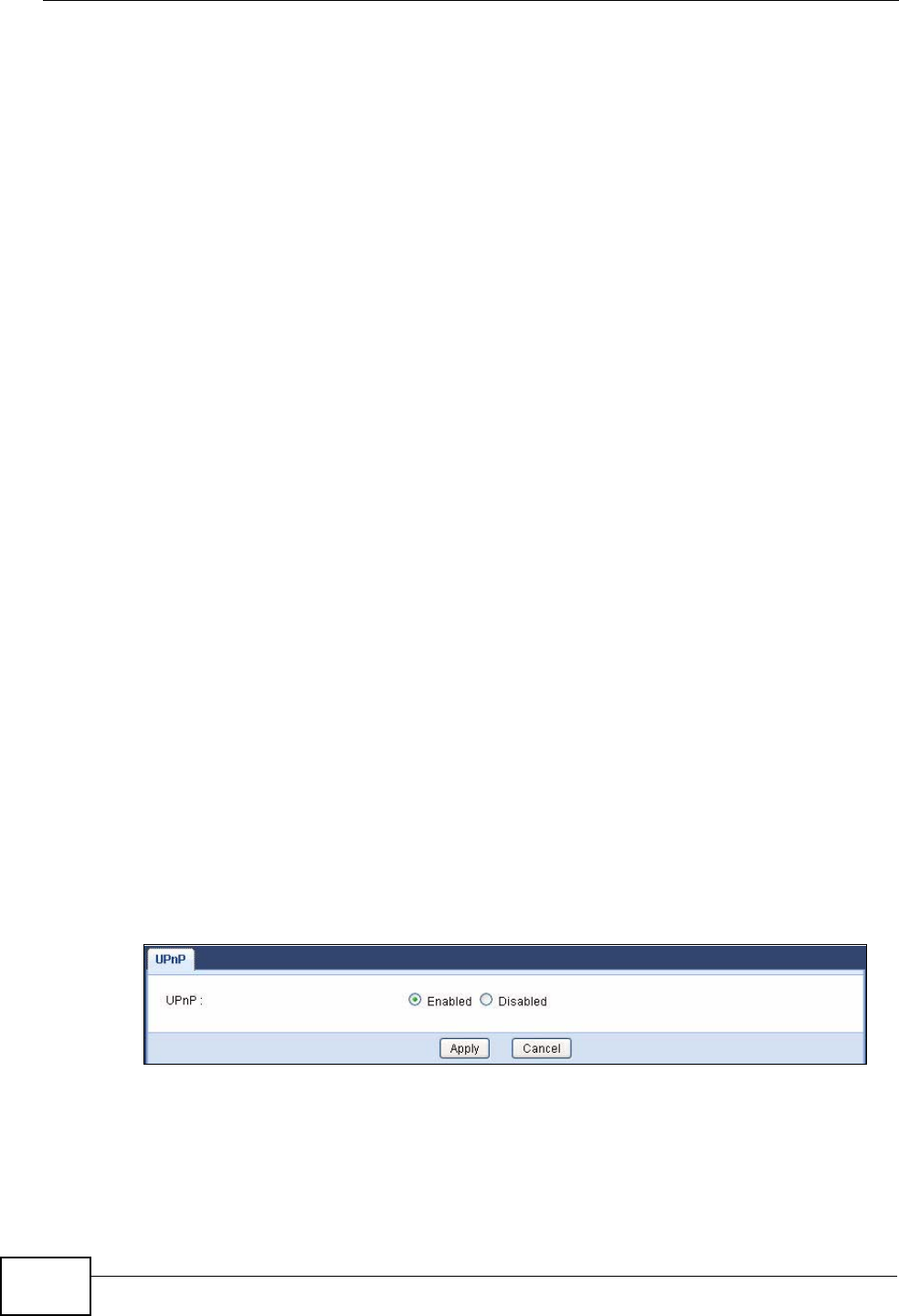
Chapter 15 Universal Plug-and-Play (UPnP)
NVG2053 User’s Guide
152
Windows Messenger is an example of an application that supports NAT traversal
and UPnP.
See the NAT chapter for more information on NAT.
Cautions with UPnP
The automated nature of NAT traversal applications in establishing their own
services and opening firewall ports may present network security issues. Network
information and configuration may also be obtained and modified by users in some
network environments.
When a UPnP device joins a network, it announces its presence with a multicast
message. For security reasons, the NVG2053 allows multicast messages on the
LAN only.
All UPnP-enabled devices may communicate freely with each other without
additional configuration. Disable UPnP if this is not your intention.
UPnP and ZyXEL
ZyXEL has achieved UPnP certification from the Universal Plug and Play Forum
UPnP™ Implementers Corp. (UIC). ZyXEL's UPnP implementation supports
Internet Gateway Device (IGD) 1.0.
See the following sections for examples of installing and using UPnP.
15.3 The UPnP Screen
Click Advanced > UPnP to display the screen shown next.
See Section 15.1 on page 151 for more information.
Figure 67 Advanced > UPnP
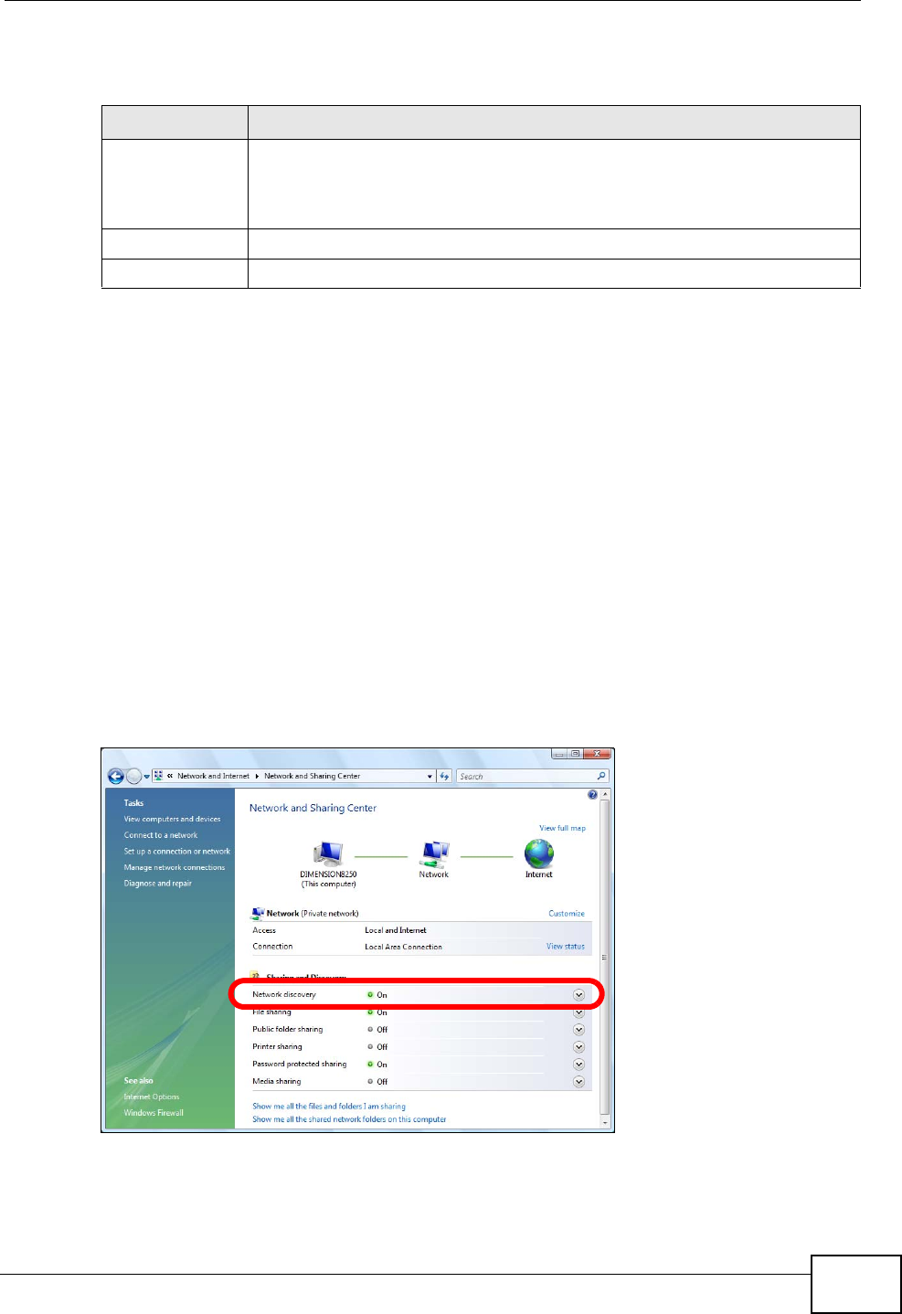
Chapter 15 Universal Plug-and-Play (UPnP)
NVG2053 User’s Guide 153
The following table describes the fields in this screen.
15.4 Installing UPnP in Windows
This section shows you how to configure or install UPnP in Windows.
15.4.1 Windows 7
Windows 7 already has UPnP installed. To enable it:
1Click Start > Control Panel and select Network and Internet.
2Click Network and Sharing Center.
3In the Network and Sharing window, set Network Discovery to On. This
activates the UPnP feature in Windows 7
Table 50 Advanced > UPnP
LABEL DESCRIPTION
UPnP Select Enabled to turn on UPnP. Be aware that anyone could use a UPnP
application to open the web configurator's login screen without entering
the NVG2053's IP address (although you must still enter the password
to access the web configurator).
Apply Click Apply to save your changes back to the NVG2053.
Cancel Click Cancel to begin configuring this screen afresh.
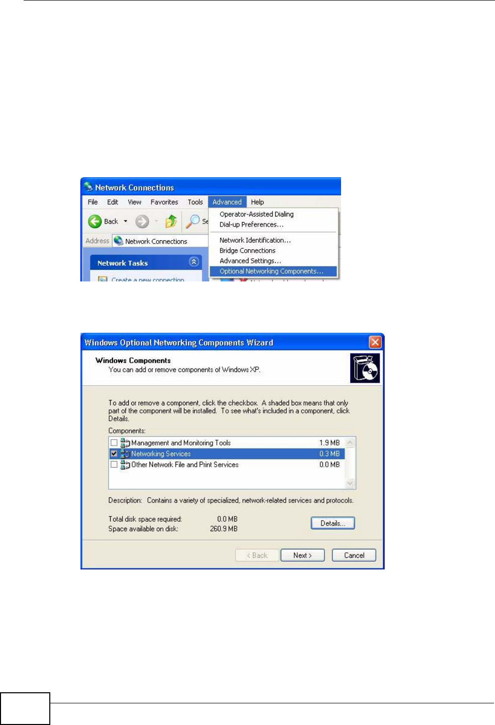
Chapter 15 Universal Plug-and-Play (UPnP)
NVG2053 User’s Guide
154
15.4.2 Windows XP
To install the UPnP in Windows XP:
1Click Start and Control Panel.
2Double-click Network Connections.
3In the Network Connections window, click Advanced in the main menu and
select Optional Networking Components ….
Network Co nnections
4The Windows Optional Networking Components Wizard window displays.
Select Networking Service in the Components selection box and click Details.
Windows Optional Networking Components Wizard
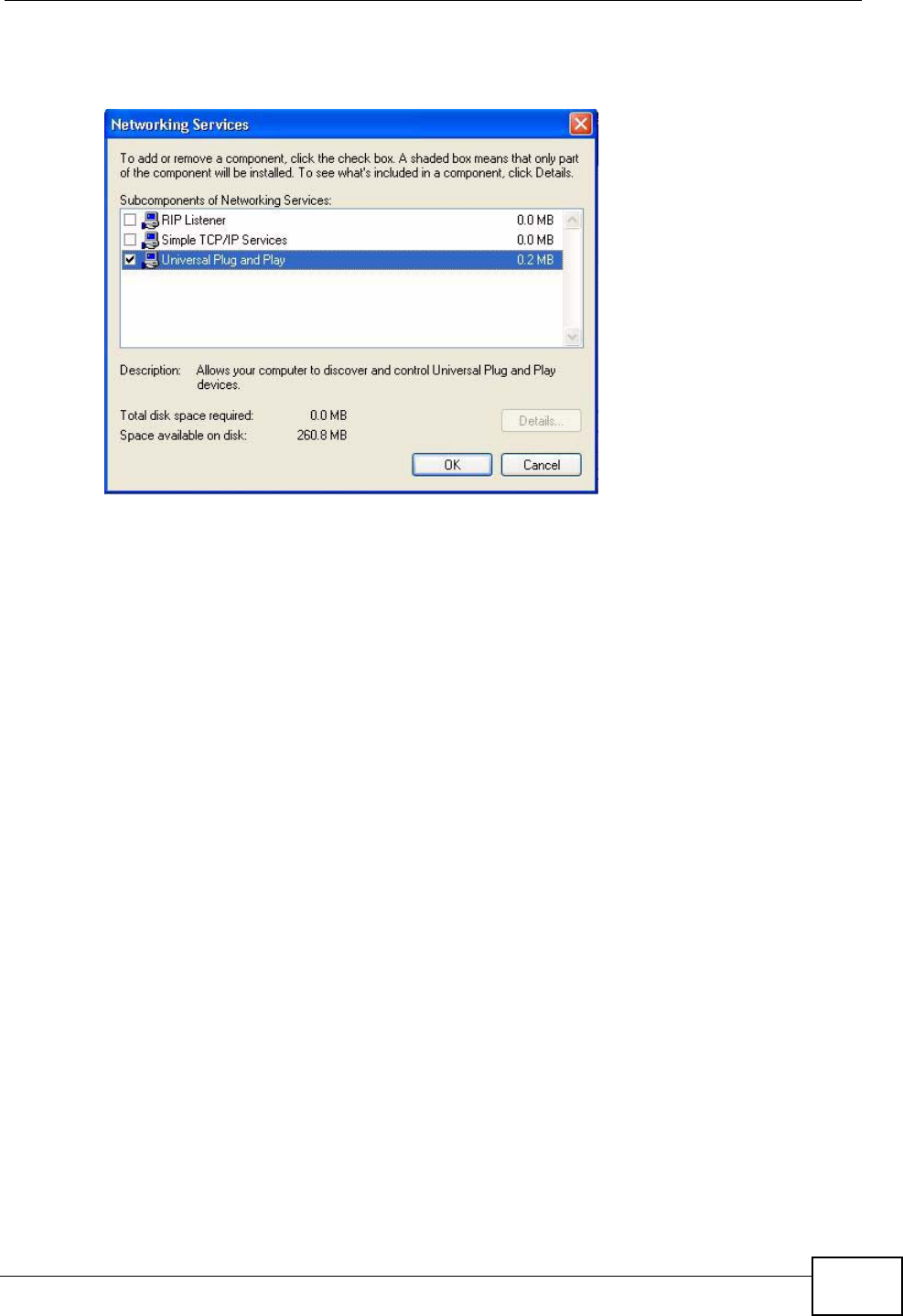
Chapter 15 Universal Plug-and-Play (UPnP)
NVG2053 User’s Guide 155
5In the Networking Services window, select the Universal Plug and Play check
box.
Networking Services
6Click OK to go back to the Windows Optional Networking Component Wizard
window and click Next.
15.5 Using UPnP in Windows XP
This section shows you how to use the UPnP feature in Windows XP. You must
already have UPnP installed in Windows XP and UPnP activated on the NVG2053.
Make sure the computer is connected to a LAN port of the NVG2053. Turn on your
computer and the NVG2053.
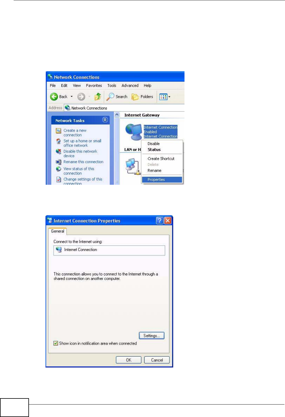
Chapter 15 Universal Plug-and-Play (UPnP)
NVG2053 User’s Guide
156
15.5.1 Auto-discover Your UPnP-enabled Network Device
1Click Start and Control Panel. Double-click Network Connections. An icon
displays under Internet Gateway.
2Right-click the icon and select Properties.
Network Co nnections
3In the Internet Connection Properties window, click Settings to see the port
mappings there were automatically created.
Internet Connection Properties
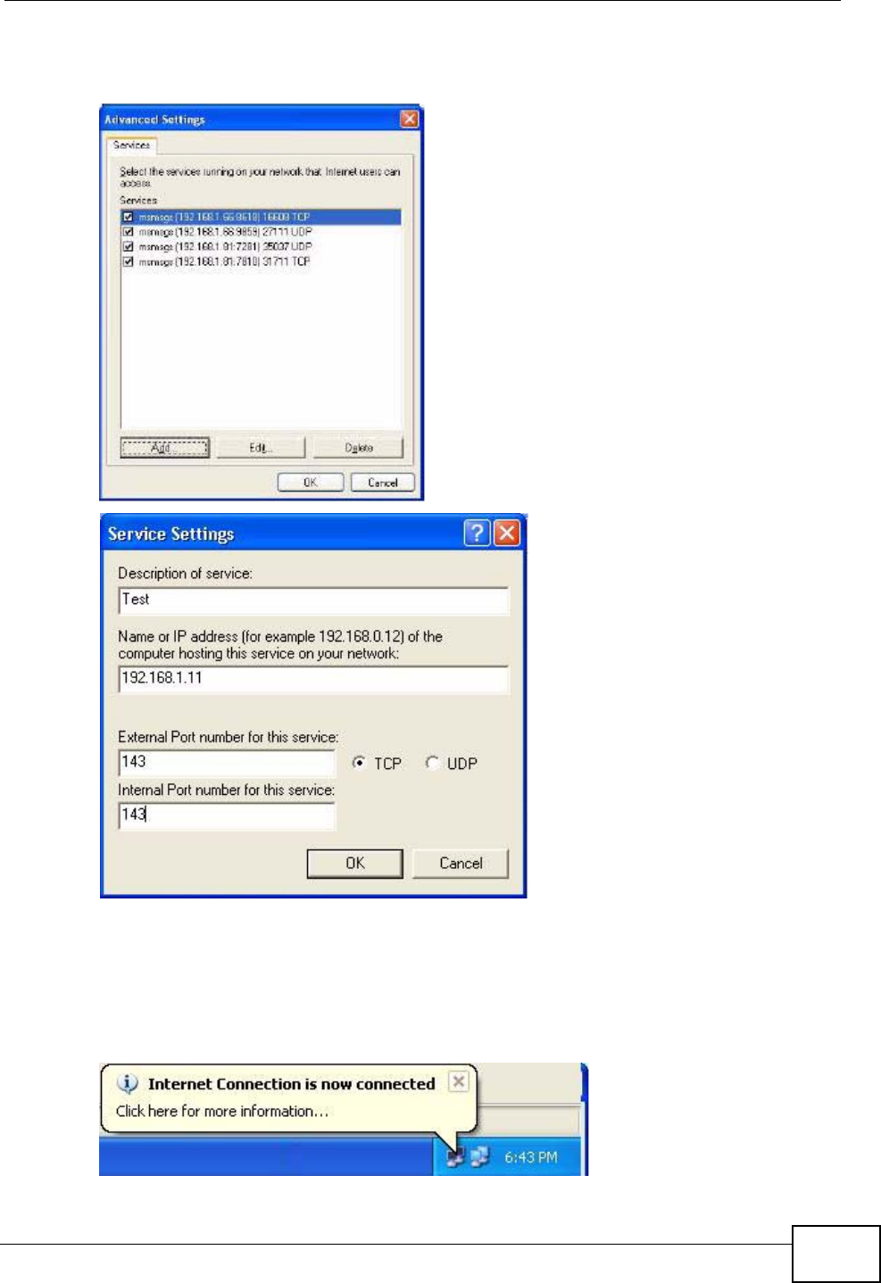
Chapter 15 Universal Plug-and-Play (UPnP)
NVG2053 User’s Guide 157
4You may edit or delete the port mappings or click Add to manually add port
mappings.
Internet Connection Properties: Advanced Settin gs
Internet Connection Properties: Advanced Settings: Add
5When the UPnP-enabled device is disconnected from your computer, all port
mappings will be deleted automatically.
6Select Show icon in notification area when connected option and click OK.
An icon displays in the system tray.
System Tray Icon
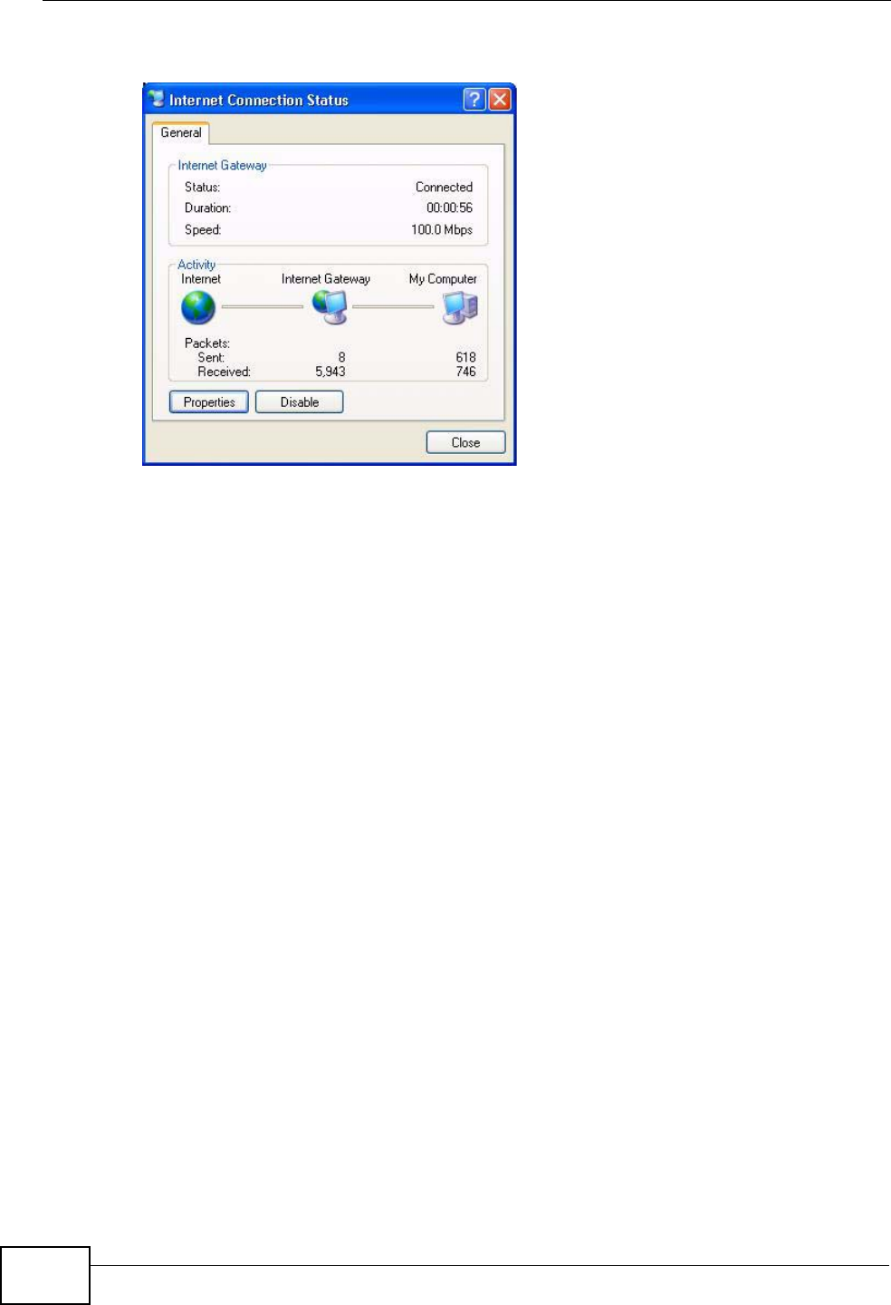
Chapter 15 Universal Plug-and-Play (UPnP)
NVG2053 User’s Guide
158
7Double-click on the icon to display your current Internet connection status.
Internet Connection Status
15.5.2 Web Configurator Easy Access
With UPnP, you can access the web-based configurator on the NVG2053 without
finding out the IP address of the NVG2053 first. This comes helpful if you do not
know the IP address of the NVG2053.
Follow the steps below to access the web configurator.
1Click Start and then Control Panel.
2Double-click Network Connections.
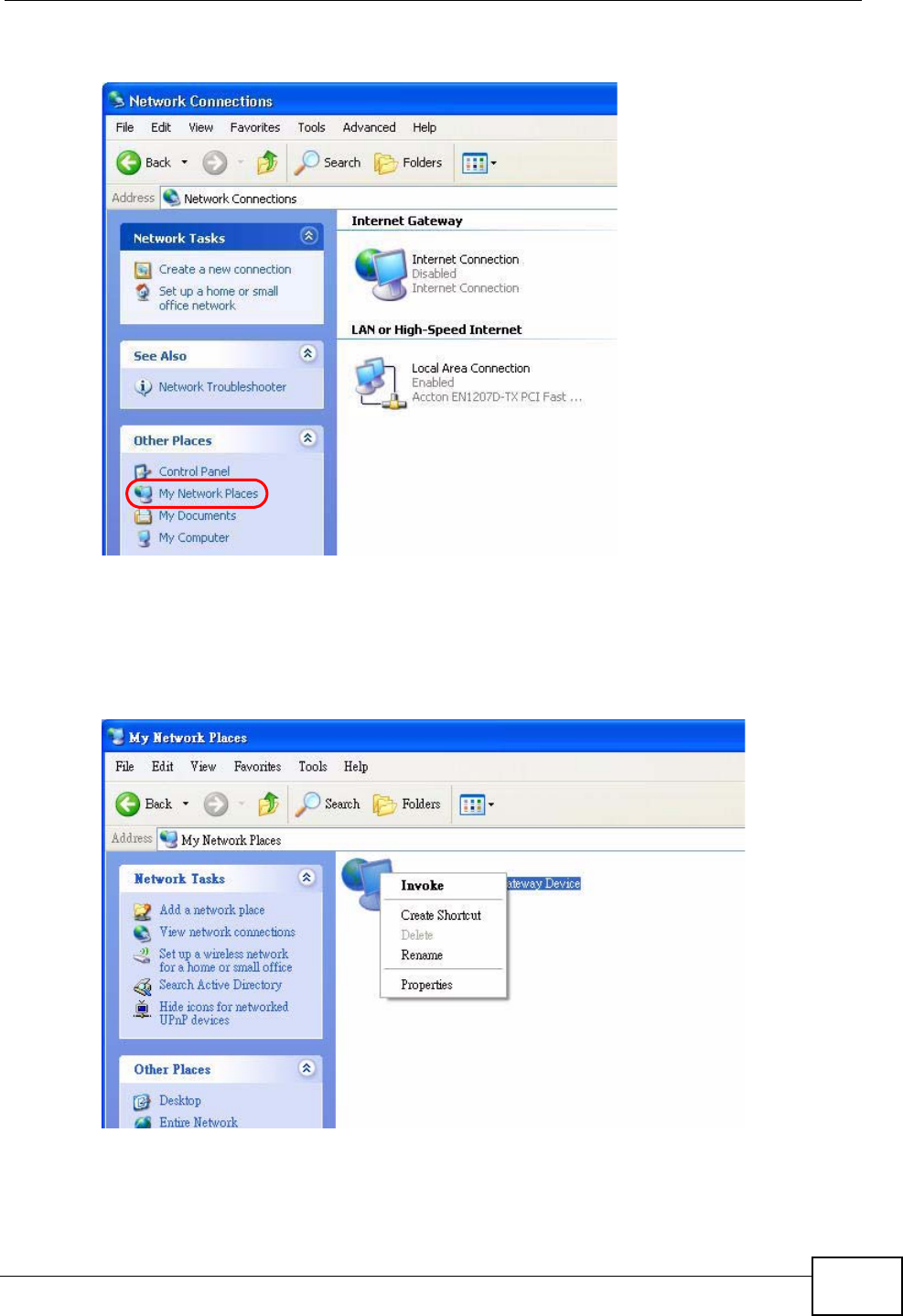
Chapter 15 Universal Plug-and-Play (UPnP)
NVG2053 User’s Guide 159
3Select My Network Places under Other Places.
Network Co nnections
4An icon with the description for each UPnP-enabled device displays under Local
Network.
5Right-click on the icon for your NVG2053 and select Invoke. The web configurator
login screen displays.
Network Co nnections: My Netw ork Places
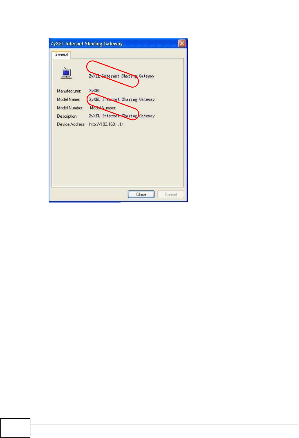
Chapter 15 Universal Plug-and-Play (UPnP)
NVG2053 User’s Guide
160
6Right-click on the icon for your NVG2053 and select Properties. A properties
window displays with basic information about the NVG2053.
Network Co nnections: My Netw ork Places: Proper ties: Example
EXAMPLE
EXAMPLE

NVG2053 User’s Guide 161
CHAPTER 16
Firewall
16.1 Overview
This chapter shows you how to enable and configure the NVG2053 firewall
settings.
The NVG2053 firewall is a packet filtering firewall and restricts access based on
the source/destination computer network address of a packet and the type of
application.
16.1.1 What You Can Do in this Chapter
•Use the General (Section 16.3 on page 162) screen to enable or disable the
NVG2053’s firewall.
•Use the Services (Section 16.4 on page 163) screen to view the configured
firewall rules and add, edit or remove a firewall rule.
16.2 What You Need To Know
Basics
Computers share information over the Internet using a common language called
TCP/IP. TCP/IP, in turn, is a set of application protocols that perform specific
functions. An “extension number”, called the "TCP port" or "UDP port" identifies
these protocols, such as HTTP (Web), FTP (File Transfer Protocol), POP3 (E-mail),
etc. For example, Web traffic by default uses TCP port 80.
When computers communicate on the Internet, they are using the client/server
model, where the server "listens" on a specific TCP/UDP port for information
requests from remote client computers on the network. For example, a Web
server typically listens on port 80. Please note that while a computer may be
intended for use over a single port, such as Web on port 80, other ports are also
active. If the person configuring or managing the computer is not careful, a hacker
could attack it over an unprotected port.
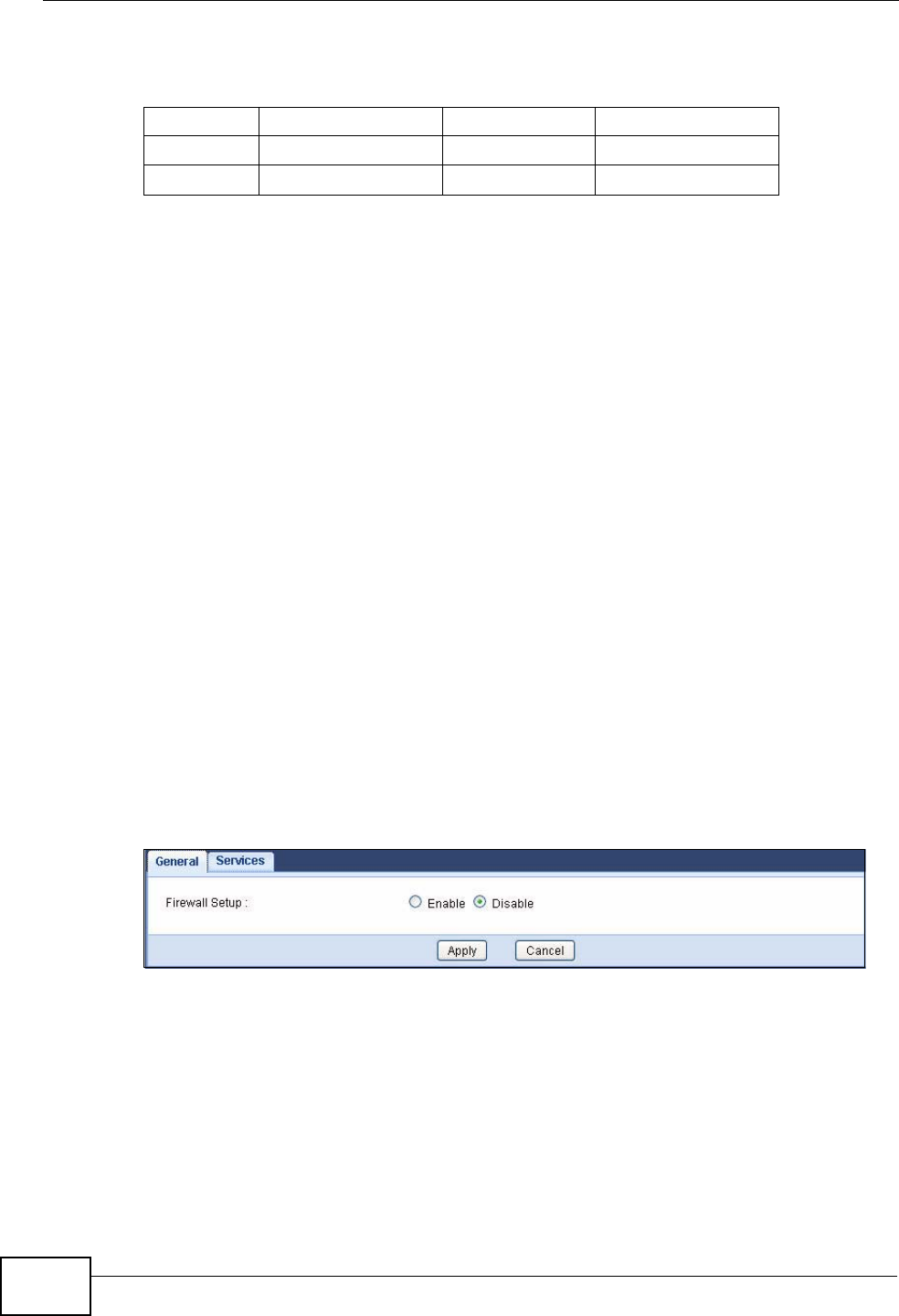
Chapter 16 Firewall
NVG2053 User’s Guide
162
Some of the most common IP ports are:
Default Filtering Policies
Filtering rules are grouped based on the direction of travel of packets to which
they apply.
The default rule for incoming traffic blocks all incoming connections from the WAN
to the LAN. If you wish to allow certain WAN users to have access to your LAN,
you will need to create custom rules to allow it.
Note: If you configure filtering rules without a good understanding of how they work,
you might inadvertently introduce security risks to the firewall and to the
protected network. Make sure you test your rules after you configure them.
These custom rules work by comparing the Source IP address, Destination IP
address and IP protocol type of network traffic to rules set by the administrator.
Your customized rules take precedence and override the NVG2053’s default rules.
16.3 The General Firewall Screen
Use this screen to enable or disable the NVG2053’s firewall. Click Configuration
> Security > Firewall to open the General screen.
Figure 68 Security > Firewall > General
Table 51 Common IP Ports
21 FTP 53 DNS
23 Telnet 80 HTTP
25 SMTP 110 POP3
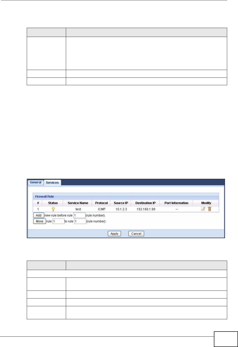
Chapter 16 Firewall
NVG2053 User’s Guide 163
The following table describes the labels in this screen.
16.4 The Services Screen
Note: The ordering of your rules is very important as rules are applied in turn.
Click Security > Firewall > Services to bring up the following screen. This
screen displays a list of the configured firewall rules. Note the order in which the
rules are listed.
Click Security > Firewall > Services. The screen appears as shown next.
Figure 69 Security > Firewall > Services
The following table describes the labels in this screen.
Table 52 Security > Firewall > General
LABEL DESCRIPTION
Firewall Setup Select Enable to activate the firewall.
When the firewall is enabled, the NVG2053 blocks all incoming traffic
from the WAN to the LAN. Create custome rules to allow certain WAN
users to access your LAN or to allow traffic from the WAN to a certain
computer on the LAN.
Apply Click Apply to save your changes back to the NVG2053.
Cancel Click Cancel to begin configuring this screen afresh.
Table 53 Security > Firewall > Services
LABEL DESCRIPTION
Firewall Rule
#This is your firewall rule number. The ordering of your rules is important
as rules are applied in turn.
Status This field displays whether a firewall rule is turned on or not.
Service Name This is a name that identifies or describes the firewall rule.
Protocol This is the protocol (TCP, UDP, ICMP or None) used to transport the
packets for which you want to apply the firewall rule.
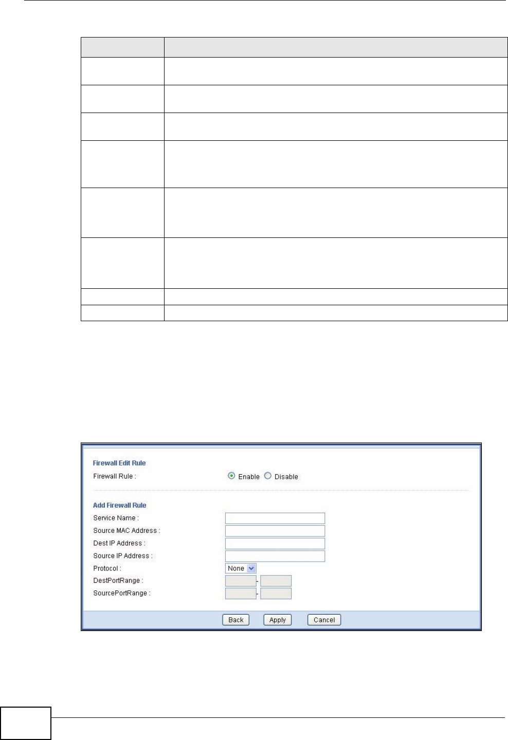
Chapter 16 Firewall
NVG2053 User’s Guide
164
16.4.1 Configuring Firewall Rules
In the Firewall > Services screen, enter an index number and click Add or click
a rule’s Edit icon to display this screen and refer to the following table for
information on the labels.
Figure 70 Security > Firewall > Services > Add
Source IP This is the IP address of the computer from which traffic for the
application or service is initialized.
Destination IP This is the IP address of the computer to which traffic for the application
or service is entering.
Port
Information This is the port number/range of the source and destination that define
the traffic type, for example TCP port 80 defines web traffic.
Modify Click the Edit icon to open a screen where you can modify an existing
rule.
Click the Remove icon to delete a rule from the NVG2053.
Add Enter an index number and click Add to add a new firewall rule before
the specified index number. For example, if you enter “6”, your new rule
becomes number 6 and the previous rule 6 (if there is one) becomes
rule 7.
Move Type a number in the first field next to the Move button and click the
Move button to move the rule to the number that you typed in the
second field next to the Move button. The ordering of your rules is
important as they are applied in order of their numbering.
Apply Click Apply to save your changes back to the NVG2053.
Cancel Click Cancel to begin configuring this screen afresh.
Table 53 Security > Firewall > Services
LABEL DESCRIPTION

Chapter 16 Firewall
NVG2053 User’s Guide 165
The following table describes the labels in this screen.
See Appendix F on page 319 for commonly used services and port numbers.
Table 54 Security > Firewall > Services > Add
LABEL DESCRIPTION
Firewall Edit Rule
Firewall Rule Select Enable to activate the firewall rule.
Add Firewall Rule
Service Name Enter a name that identifies or describes the firewall rule.
Source MAC
Address Enter the MAC address of the computer for which the firewall rule
applies.
Dest IP Address Enter the IP address of the computer to which traffic for the application
or service is entering.
The NVG2053 applies the firewall rule to traffic initiating from this
computer.
Source IP
Address Enter the IP address of the computer that initializes traffic for the
application or service.
The NVG2053 applies the firewall rule to traffic initiating from this
computer.
Protocol Select the protocol (TCP, UDP, ICMP or None) used to transport the
packets for which you want to apply the firewall rule.
DestPort Range Enter the port number/range of the destination that define the traffic
type, for example TCP port 80 defines web traffic.
SourcePort
Range Enter the port number/range of the source that define the traffic type,
for example TCP port 80 defines web traffic.
Back Click Back to return to the previous screen without saving.
Apply Click Apply to save your changes back to the NVG2053.
Cancel Click Cancel to begin configuring this screen afresh.

Chapter 16 Firewall
NVG2053 User’s Guide
166

NVG2053 User’s Guide 167
CHAPTER 17
Voice
17.1 Overview
Use this chapter to:
• Connect an analog phone to the NVG2053.
• Make phone calls over the Internet, as well as the regular phone network.
• Configure settings such as speed dial.
• Configure network settings to optimize the voice quality of your phone calls.
17.1.1 What You Can Do in this Chapter
These screens allow you to configure your NVG2053 to make phone calls over the
Internet and your regular phone line, and to set up the phones you connect to the
NVG2053.
•Use the SIP Service Provider screen (Section 17.3 on page 169) to configure
the SIP server information, QoS for VoIP calls, outbound proxy server, dialing
interval and timer settings.
•Use the SIP Account screen (Section 17.4 on page 172) to set up information
about your SIP account, configure dialing plan rules and enable certain phone
functions.
•Use the Phone Device screen (Section 17.4 on page 172) to control which SIP
accounts the phones connected to the NVG2053 use and configure audio
settings such as volume levels for the phones connected to the NVG2053.
•Use the Region screen (Section 17.6 on page 180) to change settings that
depend on the country you are in.
•Use the Speed Dial screen (Section 17.7 on page 180) to set up shortcuts for
dialing frequently-used (VoIP) phone numbers.
•Use the PSTN Call Through screen (Section 17.8 on page 182) to configure
your regular phone line.
You don’t necessarily need to use all these screens to set up your account. In fact,
if your service provider did not supply information on a particular field in a screen,
it is usually best to leave it at its default setting.

Chapter 17 Voice
NVG2053 User’s Guide
168
17.1.2 What You Need to Know
VoIP
VoIP stands for Voice over IP. IP is the Internet Protocol, which is the message-
carrying standard the Internet runs on. So, Voice over IP is the sending of voice
signals (speech) over the Internet (or another network that uses the Internet
Protocol).
SIP
SIP stands for Session Initiation Protocol. SIP is a signalling standard that lets one
network device (like a computer or the NVG2053) send messages to another. In
VoIP, these messages are about phone calls over the network. For example, when
you dial a number on your NVG2053, it sends a SIP message over the network
asking the other device (the number you dialed) to take part in the call.
SIP Accounts
A SIP account is a type of VoIP account. It is an arrangement with a service
provider that lets you make phone calls over the Internet. When you set the
NVG2053 to use your SIP account to make calls, the NVG2053 is able to send all
the information about the phone call to your service provider on the Internet.
Strictly speaking, you don’t need a SIP account. It is possible for one SIP device
(like the NVG2053) to call another without involving a SIP service provider.
However, the networking difficulties involved in doing this make it tremendously
impractical under normal circumstances. Your SIP account provider removes these
difficulties by taking care of the call routing and setup - figuring out how to get
your call to the right place in a way that you and the other person can talk to one
another.
How to Find Out More
See Chapter 2 on page 27 for a tutorial showing how to set up these screens in an
example scenario.
See Section 17.9 on page 183 for advanced technical information on SIP.
17.2 Before You Begin
• Before you can use these screens, you need to have a VoIP account already set
up. If you don’t have one yet, you can sign up with a VoIP service provider over
the Internet.
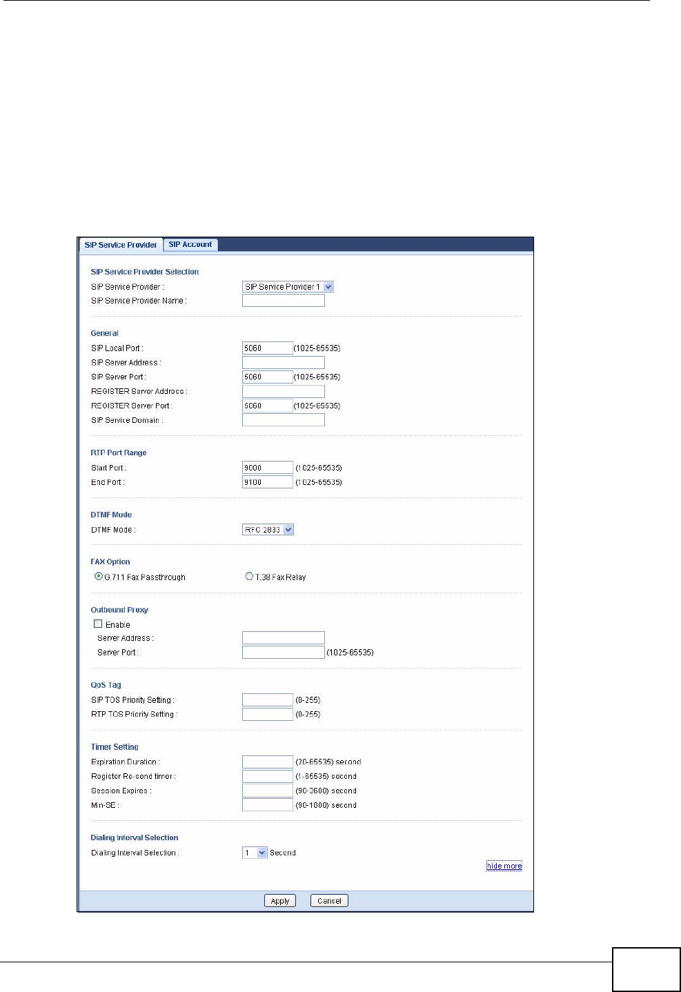
Chapter 17 Voice
NVG2053 User’s Guide 169
• You should have the information your VoIP service provider gave you ready,
before you start to configure the NVG2053.
17.3 The SIP Service Provider Screen
Click VoIP > SIP > SIP Service Provider to open the SIP Service Provider
screen. Use this screen to configure the SIP server information, QoS for VoIP calls.
Figure 71 VoIP > SIP > SIP Service Provider
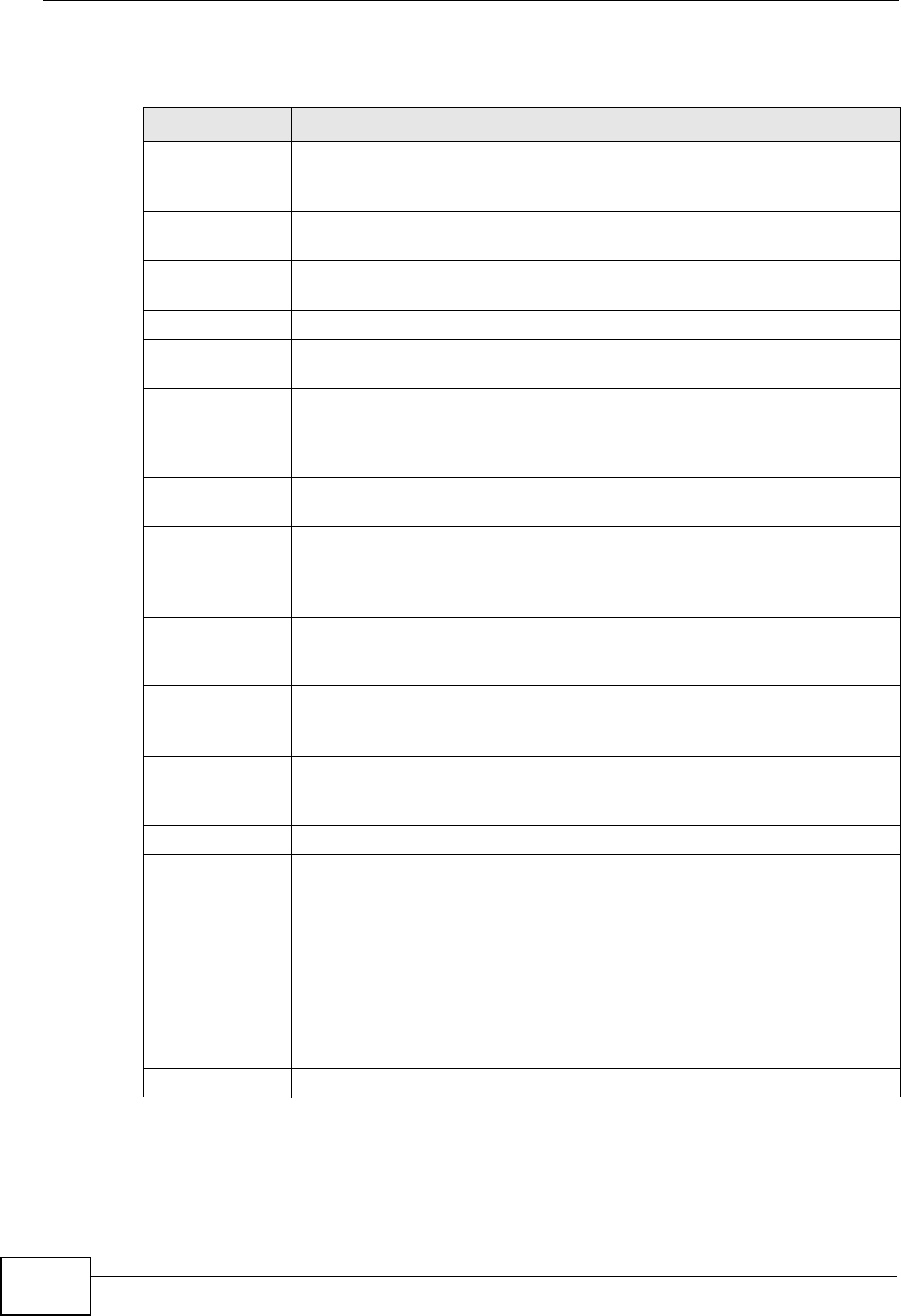
Chapter 17 Voice
NVG2053 User’s Guide
170
Each field is described in the following table.
Table 55 VoIP > SIP > SIP Service Provider
LABEL DESCRIPTION
Service
Provider
Selection
SIP Service
Provider Select the SIP service provider profile you want to see in this screen. If
you change this field, the screen automatically refreshes.
SIP Service
Provider Name Enter a descriptive name of up to 63 printable ASCII characters for this
SIP service provider profile. Spaces are not allowed.
General
SIP Local Port Enter the NVG2053’s listening port number, if your VoIP service
provider gave you one. Otherwise, keep the default value.
SIP Server
Address Enter the IP address or domain name of the SIP server provided by
your VoIP service provider. You can use up to 95 printable ASCII
characters. It does not matter whether the SIP server is a proxy,
redirect or register server.
SIP Server Port Enter the SIP server’s listening port number, if your VoIP service
provider gave you one. Otherwise, keep the default value.
REGISTER
Server Address Enter the IP address or domain name of the SIP register server, if your
VoIP service provider gave you one. Otherwise, enter the same address
you entered in the SIP Server Address field. You can use up to 95
printable ASCII characters.
REGISTER
Server Port Enter the SIP register server’s listening port number, if your VoIP
service provider gave you one. Otherwise, enter the same port number
you entered in the SIP Server Port field.
SIP Service
Domain Enter the SIP service domain name. In the full SIP URI, this is the part
after the @ symbol. You can use up to 127 printable ASCII Extended
set characters.
more.../hide
more Click more... to display and edit more information for the SIP service
provider profile. Click hide more to display and configure the basic
settings only.
RTP Port Range
Start Port
End Port
Enter the listening port number(s) for RTP traffic, if your VoIP service
provider gave you this information. Otherwise, keep the default values.
To enter one port number, enter the port number in the Start Port and
End Port fields.
To enter a range of ports,
• enter the port number at the beginning of the range in the Start
Port field.
• enter the port number at the end of the range in the End Port field.
DTMF Mode

Chapter 17 Voice
NVG2053 User’s Guide 171
DTMF Mode Control how the NVG2053 handles the tones that your telephone makes
when you push its buttons. You should use the same mode your VoIP
service provider uses.
RFC2833 - send the DTMF tones in RTP packets.
PCM - send the DTMF tones in the voice data stream. This method
works best when you are using a codec that does not use compression
(like G.711). Codecs that use compression (like G.729 and G.726) can
distort the tones.
SIP INFO - send the DTMF tones in SIP messages.
FAX Option This field controls how the NVG2053 handles fax messages.
G.711 Fax
Passthrough Select this if the NVG2053 should use G.711 to send fax messages. The
peer devices must also use G.711.
T.38 Fax
Relay Select this if the NVG2053 should send fax messages as UDP packets
through IP networks. This provides better quality, but it may have inter-
operability problems. The peer devices must also use T.38.
Outbound Proxy
Enable Select this option if your VoIP service provider has a SIP outbound
server to handle voice calls.
This allows the NVG2053 to work with any type of NAT router and
eliminates the need for STUN or a SIP ALG.
Turn off any SIP ALG on a NAT router in front of the NVG2053 to keep it
from re-translating the IP address (since this is already handled by the
outbound proxy server).
Server Address Enter the IP address or domain name of the SIP outbound proxy server.
Server Port Enter the SIP outbound proxy server’s listening port, if your VoIP
service provider gave you one. Otherwise, keep the default value.
QoS Tag
SIP TOS Priority
Setting Enter the priority for SIP voice transmissions. The NVG2053 creates
Type of Service priority tags with this priority to voice traffic that it
transmits.
RTP TOS
Priority Setting Enter the priority for RTP voice transmissions. The NVG2053 creates
Type of Service priority tags with this priority to RTP traffic that it
transmits.
Timer Setting
Expiration
Duration Enter the number of seconds your SIP account is registered with the
SIP register server before it is deleted. The NVG2053 automatically tries
to re-register your SIP account when one-half of this time has passed.
(The SIP register server might have a different expiration.)
Register Re-
send timer Enter the number of seconds the NVG2053 waits before it tries again to
register the SIP account, if the first try failed or if there is no response.
Session Expires Enter the number of seconds the NVG2053 lets a SIP session remain
idle (without traffic) before it automatically disconnects the session.
Table 55 VoIP > SIP > SIP Service Provider (continued)
LABEL DESCRIPTION
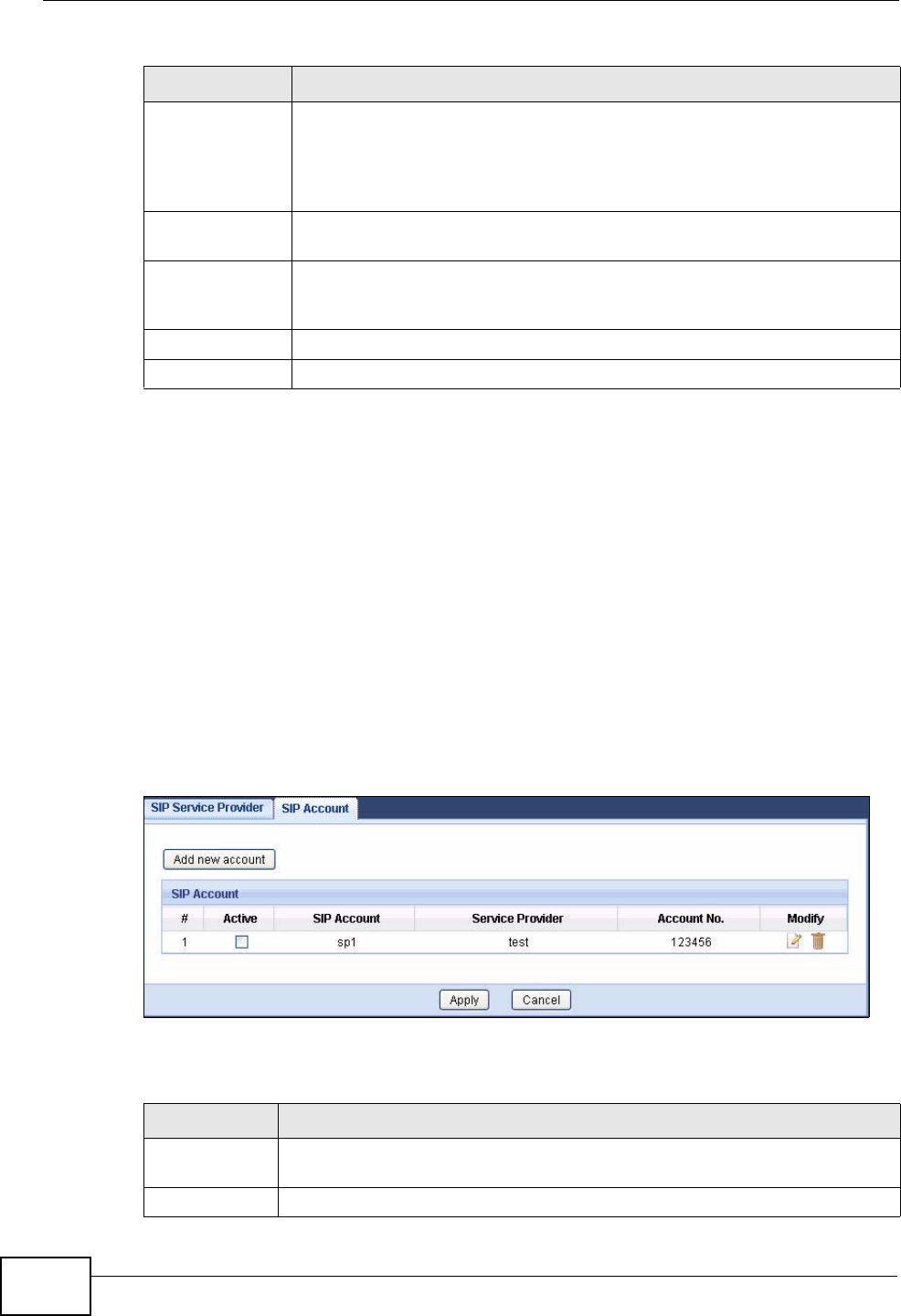
Chapter 17 Voice
NVG2053 User’s Guide
172
17.4 The SIP Account Screen
The NVG2053 uses a SIP account to make outgoing VoIP calls and check if an
incoming call’s destination number matches your SIP account’s SIP number. In
order to make or receive a VoIP call, you need to enable and configure a SIP
account, and map it to a phone port. The SIP account contains information that
allows your NVG2053 to connect to your VoIP service provider.
Use this screen to maintain information about each SIP account. You can also
enable and disable each SIP account. To access this screen, click VoIP > SIP >
SIP Account.
Figure 72 VoIP > SIP > SIP Account
The following table describes the labels in this screen.
Min-SE Enter the minimum number of seconds the NVG2053 lets a SIP session
remain idle (without traffic) before it automatically disconnects the
session. When two SIP devices start a SIP session, they must agree on
an expiration time for idle sessions. This field is the shortest expiration
time that the NVG2053 accepts.
Dialing Interval
Selection
Dialing Interval
Selection Select the number of seconds the NVG2053 should wait after you stop
dialing numbers before it makes the phone call. The value depends on
how quickly you dial phone numbers.
Apply Click this to save your changes and to apply them to the NVG2053.
Cancel Click this to set every field in this screen to its last-saved value.
Table 55 VoIP > SIP > SIP Service Provider (continued)
LABEL DESCRIPTION
Table 56 VoIP > SIP > SIP Account
LABEL DESCRIPTION
Add new
account Click this to create a new SIP account.
#This is the number of an individual account.
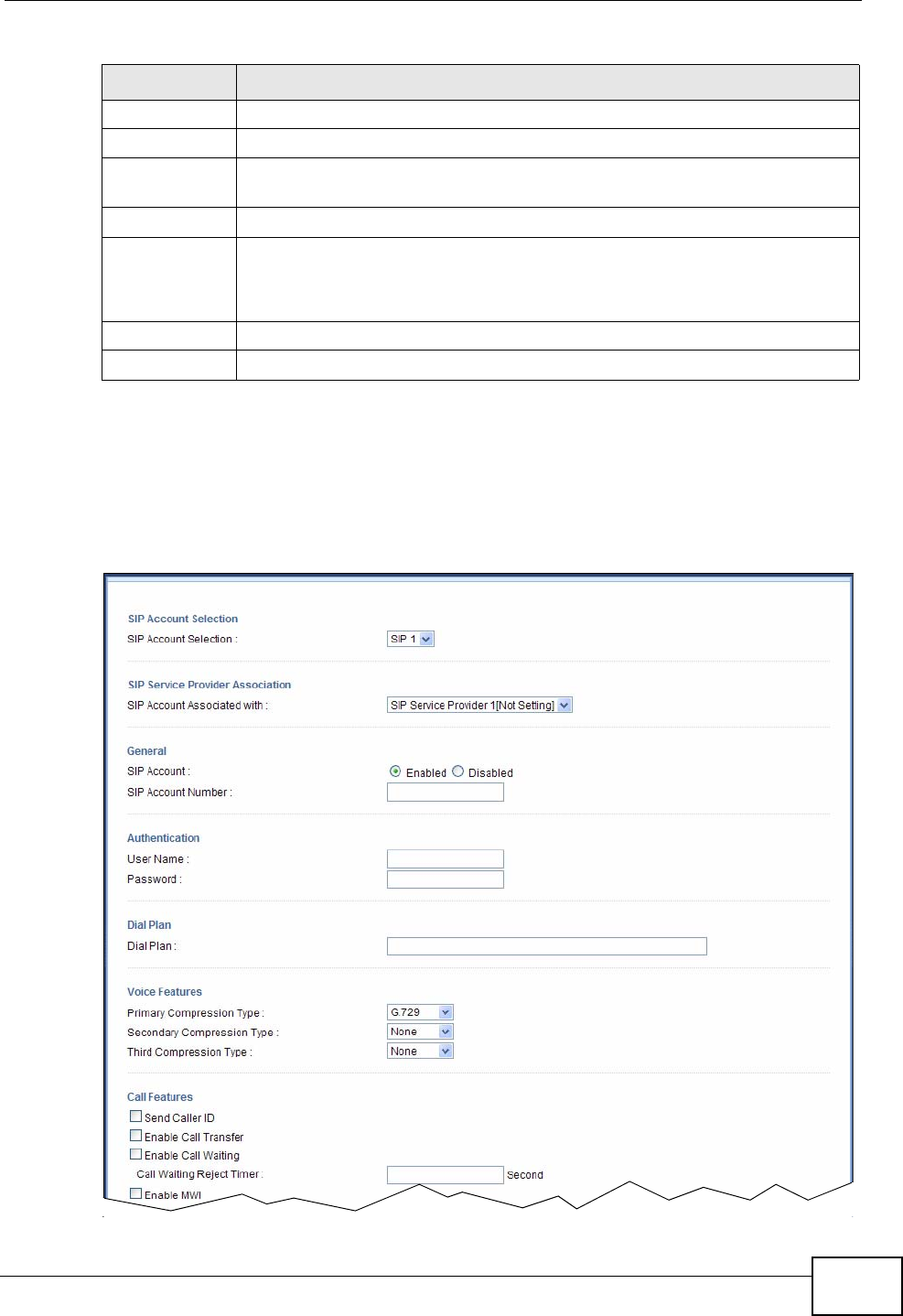
Chapter 17 Voice
NVG2053 User’s Guide 173
17.4.1 SIP Account Edit
Click the Add new account button or an entry’s Edit icon in the SIP Account
screen. Use this screen to configure the required information for a SIP account.
Figure 73 VoIP > SIP > SIP Account: Add
Active This field indicates whether the rule is active or not.
SIP Account This field displays a name to identify this account.
Service
Provider This field displays the name of the service provider profile used for this
account.
Account No. This field displays the SIP number of this account.
Modify Click the Edit icon to open a screen where you can modify an existing
account.
Click the Delete icon to remove an account from the NVG2053.
Apply Click Apply to save your changes back to the NVG2053.
Cancel Click Cancel to begin configuring this screen afresh.
Table 56 VoIP > SIP > SIP Account (continued)
LABEL DESCRIPTION
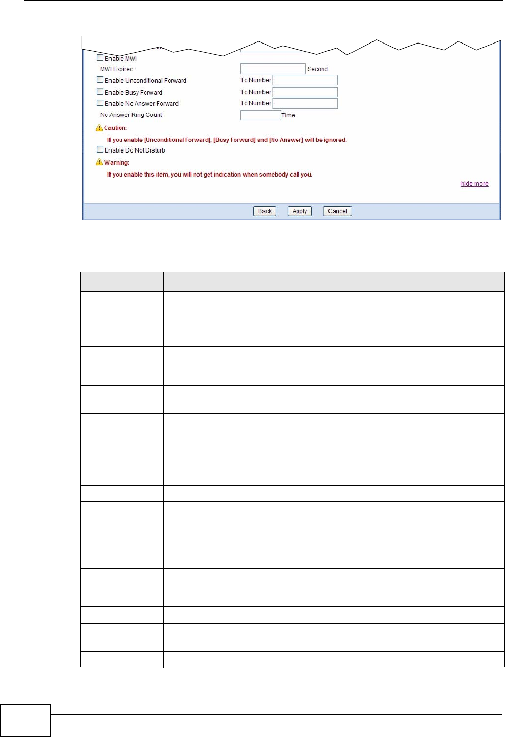
Chapter 17 Voice
NVG2053 User’s Guide
174
Each field is described in the following table.
Table 57 VoIP > SIP > SIP Account: Add
LABEL DESCRIPTION
SIP Account
Selection
SIP Account
Selection Select the SIP account you want to see in this screen. If you change this
field, the screen automatically refreshes.
SIP Service
Provider
Association
SIP Account
Associated with Select the SIP service provider profile you want to use for the SIP
account you configure in this screen.
General
SIP Account Select Enabled if you want the NVG2053 to use this account. Select
Disabled if you do not want the NVG2053 to use this account.
SIP Account
Number Enter your SIP number. In the full SIP URI, this is the part before the @
symbol. You can use up to 127 printable ASCII characters.
Authentication
User Name Enter the user name for registering this SIP account, exactly as it was
given to you. You can use up to 95 printable ASCII characters.
Password Enter the user name for registering this SIP account, exactly as it was
given to you. You can use up to 95 printable ASCII Extended set
characters.
more.../hide
more Click more... to display and edit more information for the SIP account.
Click hide more to display and configure the basic SIP account settings
only.
Dial Plan
Dial Plan Specify the dial plan rules in the text box provided. See Section 17.4.2
on page 176 for how to set up a rule.
Voice Features

Chapter 17 Voice
NVG2053 User’s Guide 175
Primary
Compression
Type
Secondary
Compression
Type
Third
Compression
Type
Select the type of voice coder/decoder (codec) that you want the
NVG2053 to use.
G.711 provides high voice quality but requires more bandwidth (64
kbps). G.711 is the default codec used by phone companies and digital
handsets.
•G.711a is typically used in Europe.
•G.711u is typically used in North America and Japan.
G.722 is a 7 KHz wideband voice codec that operates at 48, 56 and 64
kbps. By using a sample rate of 16 kHz, G.722 can provide higher
fidelity and better audio quality than narrowband codecs like G.711, in
which the voice signal is sampled at 8 KHz.
G.723.1 is an ITU (International Telecommunication Union) standard
for voice coding. The G.723.1 codec compresses voice audio in 30 ms
frames. The G.723.1 operates at two bitrates: 6.3 kbps when sampling
at 24 bytes or 5.3 kbps when sampling at 20 bytes per 30 ms frame.
G.726 is an Adaptive Differential Pulse Code Modulation (ADPCM)
waveform codec that uses a lower bitrate than standard PCM
conversion. Differential (or Delta) PCM is similar to PCM, but encodes
the audio signal based on the difference between one sample and a
prediction based on previous samples, rather than encoding the
sample’s actual quantized value. G.726 operates at 16, 24, 32 or 40
kbps.
G.729 is an Analysis-by-Synthesis (AbS) hybrid waveform codec. It
uses a filter based on information about how the human vocal tract
produces sounds. G.729 provides good sound quality and reduces the
required bandwidth to 8kbps.
The NVG2053 must use the same codec as the peer. When two SIP
devices start a SIP session, they must agree on a codec.
Select the NVG2053’s first choice for voice coder/decoder.
Select the NVG2053’s second choice for voice coder/decoder. Select
None if you only want the NVG2053 to accept the first choice.
Select the NVG2053’s third choice for voice coder/decoder. Select None
if you only want the NVG2053 to accept the first or second choice.
Call Features
Send Caller ID Select this if you want to send identification when you make VoIP phone
calls. Clear this if you do not want to send identification.
Enable Call
Transfer Select this to enable call transfer on the NVG2053. This allows you to
transfer an incoming call (that you have answered) to another phone.
Enable Call
Waiting Select this to enable call waiting on the NVG2053. This allows you to
place a call on hold while you answer another incoming call on the same
telephone number.
Call Waiting
Reject Timer Specify a time of seconds that the NVG2053 waits before rejecting the
second call if you do not answer it.
Table 57 VoIP > SIP > SIP Account: Add (continued)
LABEL DESCRIPTION
Chapter 17 Voice
NVG2053 User’s Guide
176
17.4.2 Dial Plan Rules
A dial plan defines the dialing patterns, such as the length and range of the digits
for a telephone number. It also includes country codes, access codes, area codes,
local numbers, long distance numbers or international call prefixes. For example,
the dial plan ([2-9]xxxxxx) does not allow a local number which begins with 1 or
0.
Without a dial plan, users have to manually enter the whole callee’s number and
wait for the specified dialing interval to time out or press a terminator key (usually
the pound key on the phone keypad) before the NVG2053 makes the call.
The NVG2053 initializes a call when the dialed number matches any one of the
rules in the dial plan. Dial plan rules follow these conventions:
• The collection of rules is in parentheses ().
Enable MWI Select this if you want to hear a waiting (beeping) dial tone on your
phone when you have at least one voice message. Your VoIP service
provider must support this feature.
MWI Expired Enter the number of seconds the SIP server should provide the message
waiting service each time the NVG2053 subscribes to the service.
Before this time passes, the NVG2053 automatically subscribes again.
Enable
Unconditional
Forward
Select this if you want the NVG2053 to forward all incoming calls to the
specified phone number.
Specify the phone number in the To Number field on the right.
Enable Busy
Forward Select this if you want the NVG2053 to forward incoming calls to the
specified phone number if the phone port is busy.
Specify the phone number in the To Number field on the right.
If you have call waiting, the incoming call is forwarded to the specified
phone number if you reject or ignore the second incoming call.
Enable No
Answer Forward Select this if you want the NVG2053 to forward incoming calls to the
specified phone number if the call is unanswered. (See No Answer
Ring Count.)
Specify the phone number in the To Number field on the right.
No Answer Ring
Count This field is used by the Active No Answer Forward feature.
Enter the number of telephone rings the NVG2053 should wait for you
to answer an incoming call before it considers the call is unanswered.
Enable Do Not
Disturb Select this to set your phone to not ring when someone calls you.
Back Click Back to return to the previous screen without saving.
Apply Click Apply to save your changes back to the NVG2053.
Cancel Click Cancel to set every field in this screen to its last-saved value.
Table 57 VoIP > SIP > SIP Account: Add (continued)
LABEL DESCRIPTION
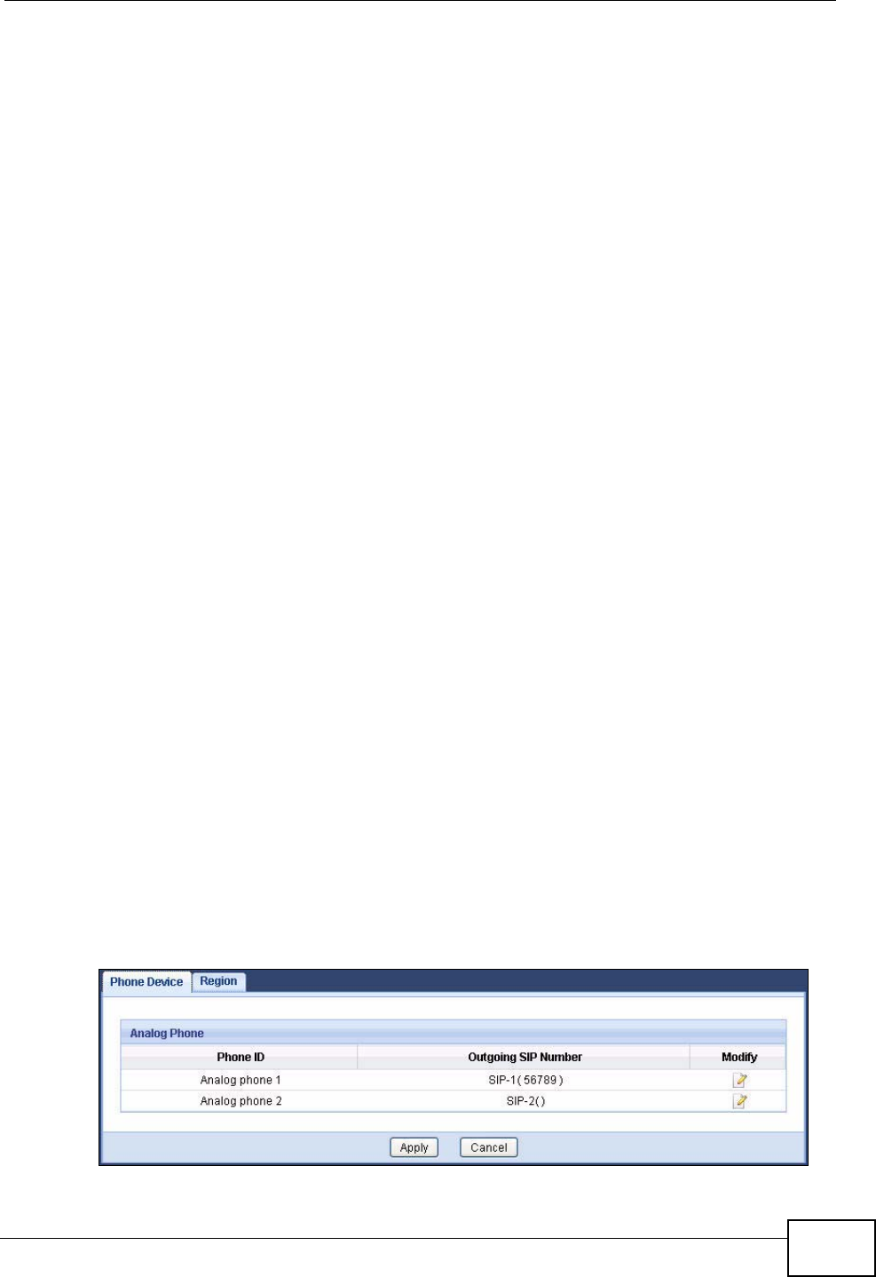
Chapter 17 Voice
NVG2053 User’s Guide 177
• Rules are separated by the | (bar) symbol.
• “x” stands for a wildcard and can be any digit from 0 to 9.
• A subset of keys is in a square bracket []. Ranges are allowed.
For example, [359] means a number matching this rule can be 3, 5 or 9. [26-
8*] means a number matching this rule can be 2, 6, 7, 8 or *.
• The dot “.” appended to a digit allows the digit to be ignored or repeated
multiple times. Any digit (0~9, *, #) after the dot will be ignored.
For example, (01.) means a number matching this rule can be 0, 01, 0111,
01111, and so on.
• <dialed-number:translated-number> indicates the number after the colon
replaces the number before the colon in an angle bracket <>. For example,
(<:1212> xxxxxxx) means the NVG2053 automatically prefixes the translated-
number “1212” to the number you dialed before making the call. This can be
used for local calls in the US.
(<9:> xxx xxxxxxx) means the NVG2053 automatically removes the specified
prefix “9” from the number you dialed before making the call. This is always
used for making outside calls from an office.
(xx<123:456>xxxx) means the NVG2053 automatically translates “123” to
“456” in the number you dialed before making the call.
• Calls with a number followed by the exclamation mark “!” will be dropped.
• Calls with a number followed by the termination character “@” will be made
immediately. Any digit (0~9, *, #) after the @ character will be ignored.
In this example dial plan (0 | [49]11 | 1 [2-9]xx xxxxxxx | 1 947 xxxxxxx !), you
can dial “0” to call the local operator, call 411 or 911, or make a long distance call
with an area code starting from 2 to 9 in the US. The calls with the area code 947
will be dropped.
17.5 The Phone Device Screen
Use this screen to view and control which SIP accounts each phone uses. To
access this screen, click VoIP > Phone > Phone Device.
Figure 74 VoIP > Phone > Phone Device
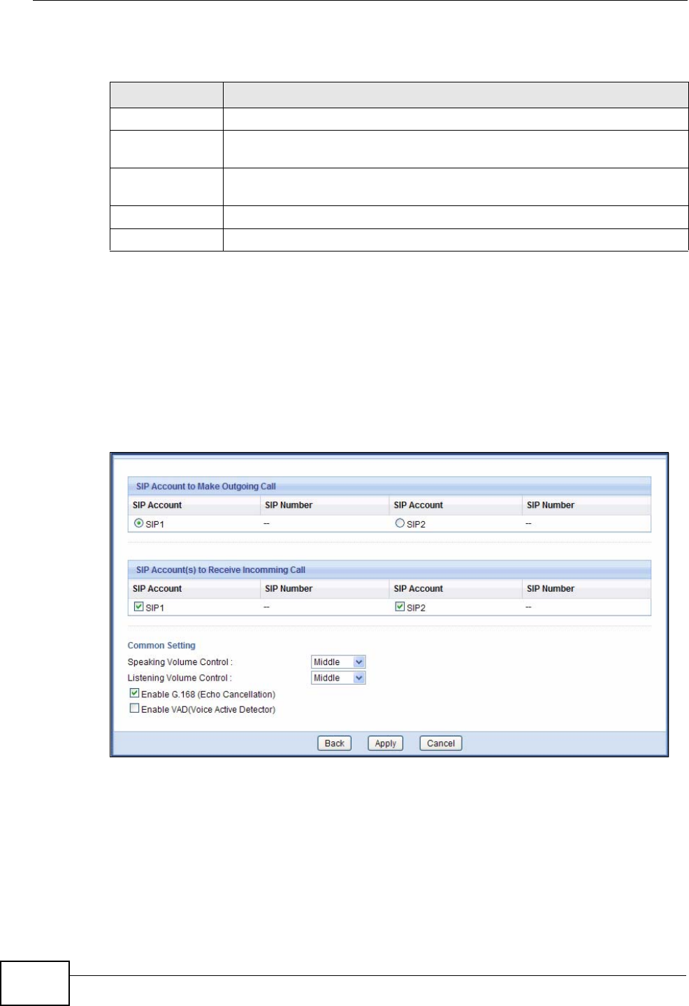
Chapter 17 Voice
NVG2053 User’s Guide
178
Each field is described in the following table.
17.5.1 The Phone Device Edit Screen
Use this screen to select which SIP account to use for making or receiving phone
calls on each individual phone port of the NVG2053. You can also configure the
echo cancellation and VAD (Voice Activity Detection) settings.
Click a phone port’s Edit icon in the Phone Device screen.
Figure 75 VoIP > Phone > Phone Device: Edit
Table 58 VoIP > Phone > Phone Device
LABEL DESCRIPTION
Phone ID This is the phone port in the NVG2053.
Outgoing SIP
Number This field displays the SIP account you want to use when making
outgoing calls with the analog phone connected to this phone port.
Modify Click the Edit icon to open a screen where you can change the phone
port settings.
Apply Click Apply to save your changes back to the NVG2053.
Cancel Click Cancel to begin configuring this screen afresh.

Chapter 17 Voice
NVG2053 User’s Guide 179
Each field is described in the following table.
Table 59 VoIP > Phone > Phone Device: Edit
LABEL DESCRIPTION
SIP Account to
Make Outgoing
Call
SIP Account Select the SIP account you want to use when making outgoing calls with
the analog phone connected to this phone port.
SIP Number This field displays the SIP number of the account.
SIP Account(s)
to Receive
Incomming Call
SIP Account Select the SIP account(s) for which you want to receive phone calls on
this phone port.
If you select more than one source for incoming calls, there is no way to
distinguish between them when you receive phone calls. If you do not
select a source for incoming calls, you cannot receive any calls on this
phone port.
SIP Number This field displays the SIP number of the account.
Common
Setting
Speaking
Volume Control Enter the loudness that the NVG2053 uses for speech that it sends to
the peer device.
Minimum is the quietest, and Maximum is the loudest.
Listening
Volume Control Enter the loudness that the NVG2053 uses for speech that it receives
from the peer device.
Minimum is the quietest, and Maximum is the loudest.
Enable G.168
(Echo
Cancellation)
Select this if you want to eliminate the echo caused by the sound of
your voice reverberating in the telephone receiver while you talk.
Enable VAD
(Voice Active
Detector)
Select this if the NVG2053 should stop transmitting when you are not
speaking. This reduces the bandwidth the NVG2053 uses.
Back Click Back to return to the previous screen without saving.
Apply Click Apply to save your changes back to the NVG2053.
Cancel Click Cancel to set every field in this screen to its last-saved value.
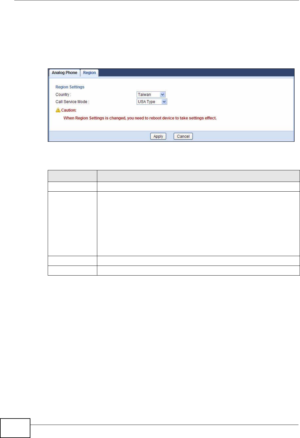
Chapter 17 Voice
NVG2053 User’s Guide
180
17.6 The Phone Region Screen
Use this screen to maintain settings that depend on which region of the world the
NVG2053 is in. To access this screen, click VoIP > Phone > Region.
Figure 76 VoIP > Phone > Region
Each field is described in the following table.
17.7 The Speed Dial Screen
Use this screen to add, edit, or remove speed-dial numbers for outgoing calls.
Speed dial provides shortcuts for dialing frequently-used (VoIP) phone numbers.
You also have to create speed-dial entries if you want to call SIP numbers that
contain letters. Once you have configured a speed dial rule, you can use a shortcut
(the speed dial number, #01 for example) on your phone's keypad to call the
phone number.
Table 60 VoIP > Phone > Region
LABEL DESCRIPTION
Country Select the place in which the NVG2053 is located.
Call Service
Mode Select the mode for supplementary phone services (call hold, call
waiting, call transfer and three-way conference calls) that your VoIP
service provider supports.
Europe Type - use supplementary phone services in European mode
USA Type - use supplementary phone services American mode
You might have to subscribe to these services to use them. Contact your
VoIP service provider.
Apply Click this to save your changes and to apply them to the NVG2053.
Cancel Click this to set every field in this screen to its last-saved value.
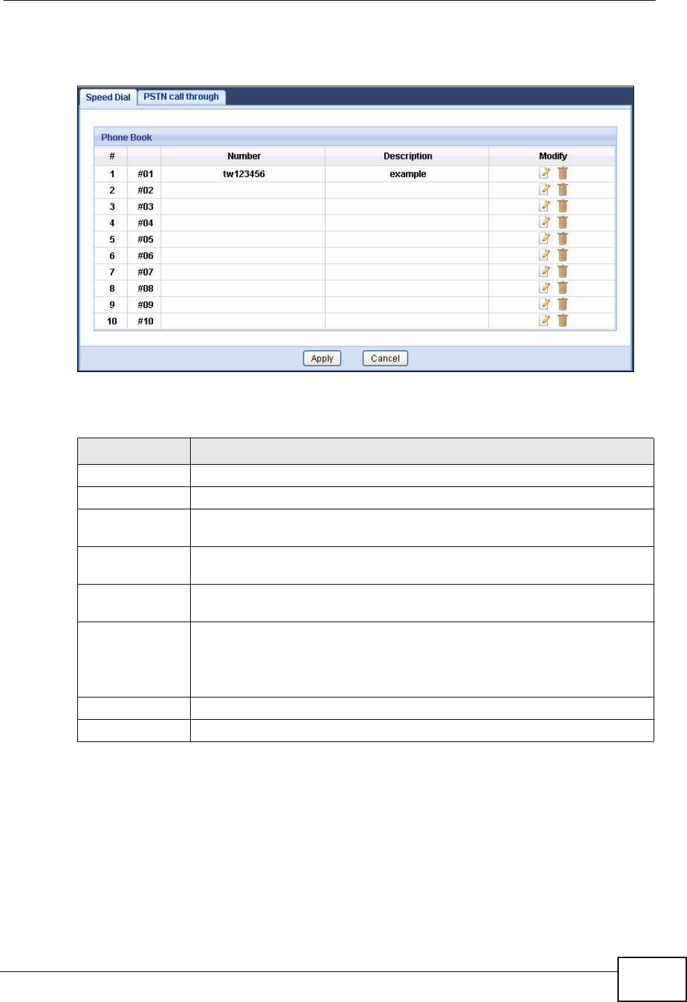
Chapter 17 Voice
NVG2053 User’s Guide 181
To access this screen, click VoIP > Call Rules > Speed Dial.
Figure 77 VoIP > Call Rules > Speed Dial
Each field is described in the following table.
Table 61 VoIP > Phone Book > Speed Dial
LABEL DESCRIPTION
Phone Book Use this section to look at all the speed-dial entries and to edit them.
# This field displays the index number of each entry.
This field displays the speed-dial number you should dial to use this
entry.
Number This field displays the SIP number the NVG2053 calls when you dial the
speed-dial number.
Description This field displays the name of the party you call when you dial the
speed-dial number.
Modify Use this field to edit or erase the speed-dial entry.
Click the Edit icon to open a screen where you can modify an entry.
Click the Delete icon to erase this speed-dial entry.
Apply Click Apply to save your changes back to the NVG2053.
Cancel Click Cancel to begin configuring this screen afresh.
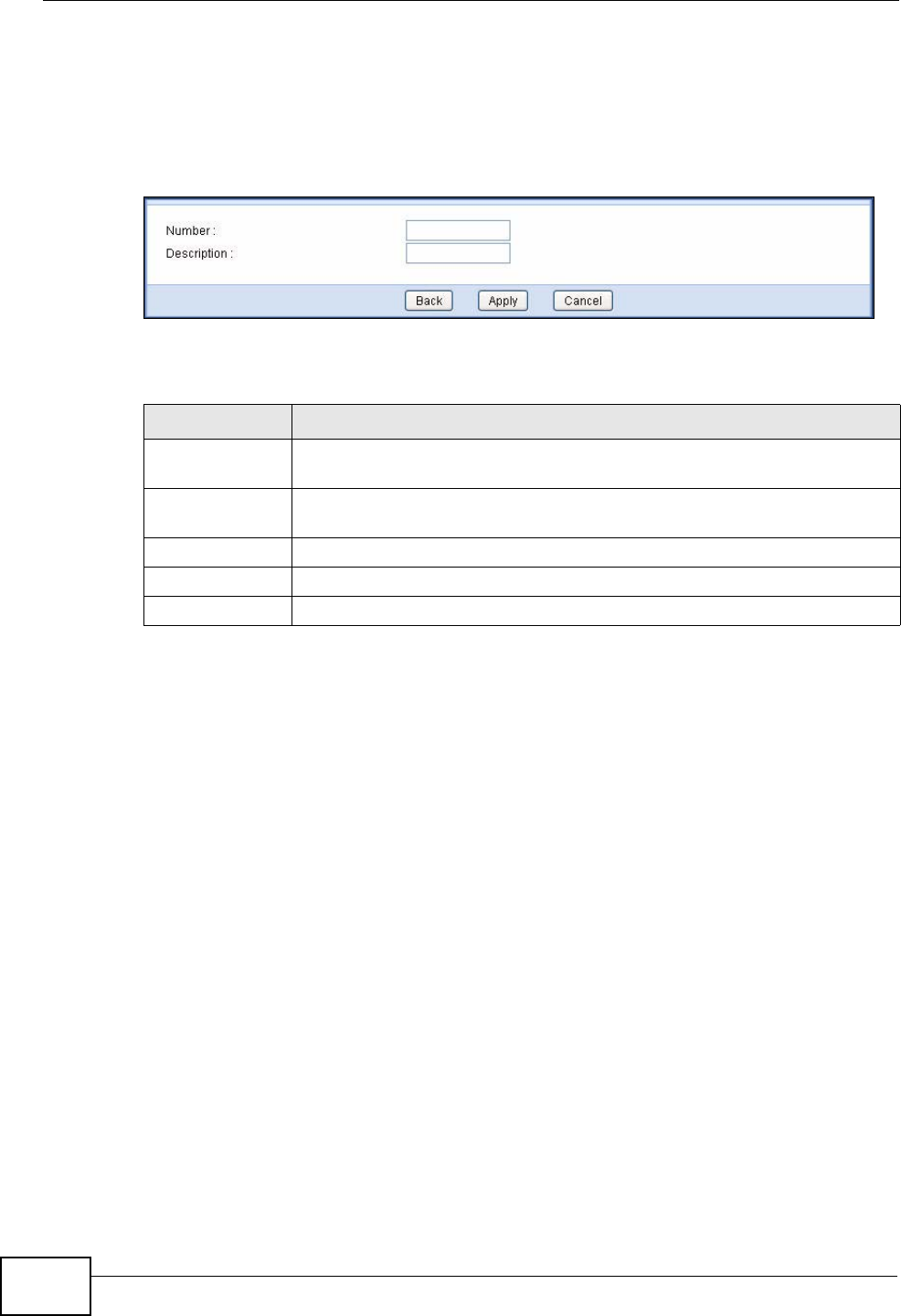
Chapter 17 Voice
NVG2053 User’s Guide
182
17.7.1 The Speed Dial Edit Screen
Use this screen to create or edit speed-dial entries. Click an entry’s Edit icon in
the Speed Dial screen.
Figure 78 VoIP > Call Rules > Speed Dial: Edit
Each field is described in the following table.
17.8 The PSTN call through Screen
Use this screen to set up the PSTN line you use to make regular PSTN phone calls.
Use a prefix number to make a regular call. When the device does not have power,
you can make regular calls without dialing a prefix number.
When the VoIP service is not available or the NVG2053 does not
have power, the phone(s) connected to the PHONE 2 port can still
be used for making PSTN calls.
You can also use the PSTN call through screen to specify phone numbers that
should always use the regular phone service (without having to dial a prefix
number). Do this for emergency numbers (like those for contacting police, fire or
emergency medical services).
Table 62 VoIP > Phone Book > Speed Dial: Edit
LABEL DESCRIPTION
Number Enter the SIP number you want the NVG2053 to call when you dial the
speed-dial number.
Description Enter a name to identify the party you call when you dial the speed-dial
number. You can use up to 127 printable ASCII characters.
Back Click Back to return to the previous screen without saving.
Apply Click Apply to save your changes back to the NVG2053.
Cancel Click Cancel to set every field in this screen to its last-saved value.
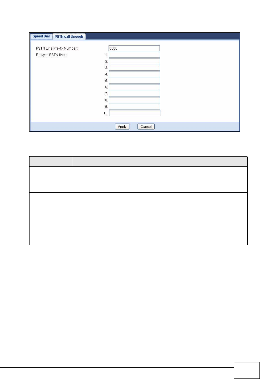
Chapter 17 Voice
NVG2053 User’s Guide 183
To access this screen, click VoIP > Call Rules > PSTN call through.
Figure 79 VoIP > Call Rules > PSTN call through
Each field is described in the following table.
17.9 Technical Reference
This section contains background material relevant to the VoIP screens.
VoIP
VoIP is the sending of voice signals over Internet Protocol. This allows you to
make phone calls and send faxes over the Internet at a fraction of the cost of
using the traditional circuit-switched telephone network. You can also use servers
to run telephone service applications like PBX services and voice mail. Internet
Telephony Service Provider (ITSP) companies provide VoIP service.
Table 63 VoIP > PSTN Line > General
LABEL DESCRIPTION
PSTN Line Pre-
fix Number Enter a prefix (up to seven numbers) you dial before you dial the phone
number, if you want to make a regular phone call while one of your SIP
accounts is registered. These numbers tell the NVG2053 that you want
to make a regular phone call.
Relay to PSTN
Line Enter phone numbers (for regular calls, not VoIP calls) that you want to
dial without the prefix number. For example, you should enter
emergency numbers.
The number (1 - 9) is not a speed-dial number. It is just a sequential
value that is not associated with any phone number.
Apply Click this to save your changes and to apply them to the NVG2053.
Cancel Click this to set every field in this screen to its last-saved value.

Chapter 17 Voice
NVG2053 User’s Guide
184
Circuit-switched telephone networks require 64 kilobits per second (Kbps) in each
direction to handle a telephone call. VoIP can use advanced voice coding
techniques with compression to reduce the required bandwidth.
SIP
The Session Initiation Protocol (SIP) is an application-layer control (signaling)
protocol that handles the setting up, altering and tearing down of voice and
multimedia sessions over the Internet.
SIP signaling is separate from the media for which it handles sessions. The media
that is exchanged during the session can use a different path from that of the
signaling. SIP handles telephone calls and can interface with traditional circuit-
switched telephone networks.
SIP Identities
A SIP account uses an identity (sometimes referred to as a SIP address). A
complete SIP identity is called a SIP URI (Uniform Resource Identifier). A SIP
account's URI identifies the SIP account in a way similar to the way an e-mail
address identifies an e-mail account. The format of a SIP identity is SIP-
Number@SIP-Service-Domain.
SIP Number
The SIP number is the part of the SIP URI that comes before the “@” symbol. A
SIP number can use letters like in an e-mail address (johndoe@your-ITSP.com for
example) or numbers like a telephone number (1122334455@VoIP-provider.com
for example).
SIP Service Domain
The SIP service domain of the VoIP service provider is the domain name in a SIP
URI. For example, if the SIP address is 1122334455@VoIP-provider.com, then
“VoIP-provider.com” is the SIP service domain.
SIP Registration
Each NVG2053 is an individual SIP User Agent (UA). To provide voice service, it
has a public IP address for SIP and RTP protocols to communicate with other
servers.
A SIP user agent has to register with the SIP registrar and must provide
information about the users it represents, as well as its current IP address (for the
routing of incoming SIP requests). After successful registration, the SIP server
knows that the users (identified by their dedicated SIP URIs) are represented by
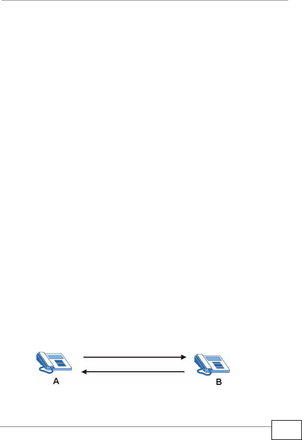
Chapter 17 Voice
NVG2053 User’s Guide 185
the UA, and knows the IP address to which the SIP requests and responses should
be sent.
Registration is initiated by the User Agent Client (UAC) running in the VoIP
gateway (the NVG2053). The gateway must be configured with information letting
it know where to send the REGISTER message, as well as the relevant user and
authorization data.
A SIP registration has a limited lifespan. The User Agent Client must renew its
registration within this lifespan. If it does not do so, the registration data will be
deleted from the SIP registrar's database and the connection broken.
The NVG2053 attempts to register all enabled subscriber ports when it is switched
on. When you enable a subscriber port that was previously disabled, the NVG2053
attempts to register the port immediately.
Authorization Requirements
SIP registrations (and subsequent SIP requests) require a username and
password for authorization. These credentials are validated via a challenge /
response system using the HTTP digest mechanism (as detailed in RFC3261, "SIP:
Session Initiation Protocol").
SIP Servers
SIP is a client-server protocol. A SIP client is an application program or device that
sends SIP requests. A SIP server responds to the SIP requests.
When you use SIP to make a VoIP call, it originates at a client and terminates at a
server. A SIP client could be a computer or a SIP phone. One device can act as
both a SIP client and a SIP server.
SIP User Agent
A SIP user agent can make and receive VoIP telephone calls. This means that SIP
can be used for peer-to-peer communications even though it is a client-server
protocol. In the following figure, either A or B can act as a SIP user agent client to
initiate a call. A and B can also both act as a SIP user agent to receive the call.
Figure 80 SIP User Agent
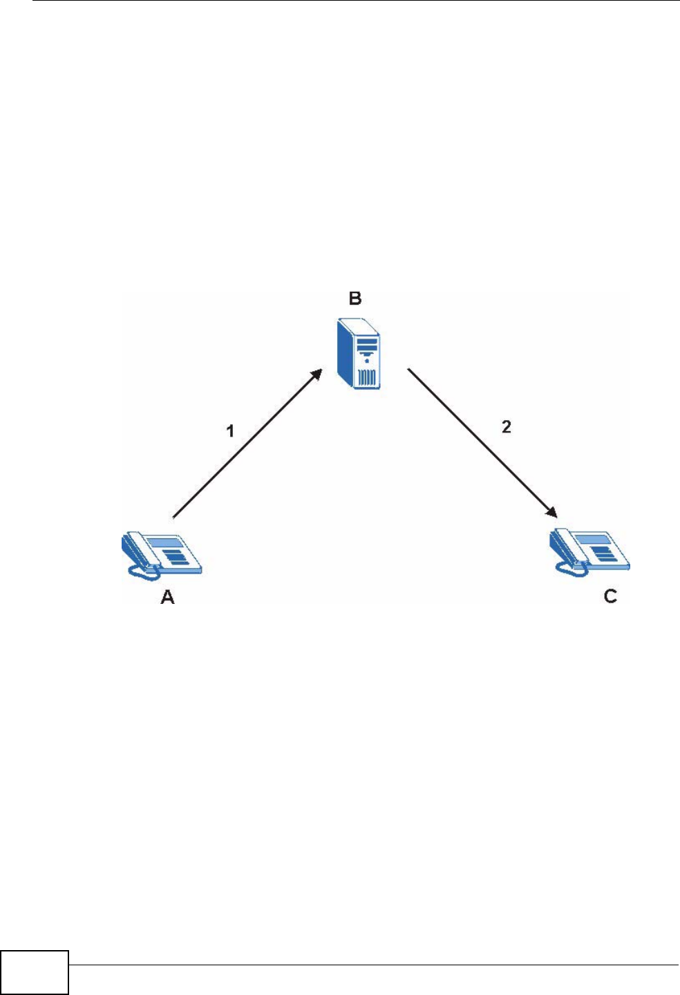
Chapter 17 Voice
NVG2053 User’s Guide
186
SIP Proxy Server
A SIP proxy server receives requests from clients and forwards them to another
server.
In the following example, you want to use client device A to call someone who is
using client device C.
1The client device (A in the figure) sends a call invitation to the SIP proxy server
(B).
2The SIP proxy server forwards the call invitation to C.
Figure 81 SIP Proxy Server
SIP Redirect Server
A SIP redirect server accepts SIP requests, translates the destination address to
an IP address and sends the translated IP address back to the device that sent the
request. Then the client device that originally sent the request can send requests
to the IP address that it received back from the redirect server. Redirect servers
do not initiate SIP requests.
In the following example, you want to use client device A to call someone who is
using client device C.
1Client device A sends a call invitation for C to the SIP redirect server (B).
2The SIP redirect server sends the invitation back to A with C’s IP address (or
domain name).
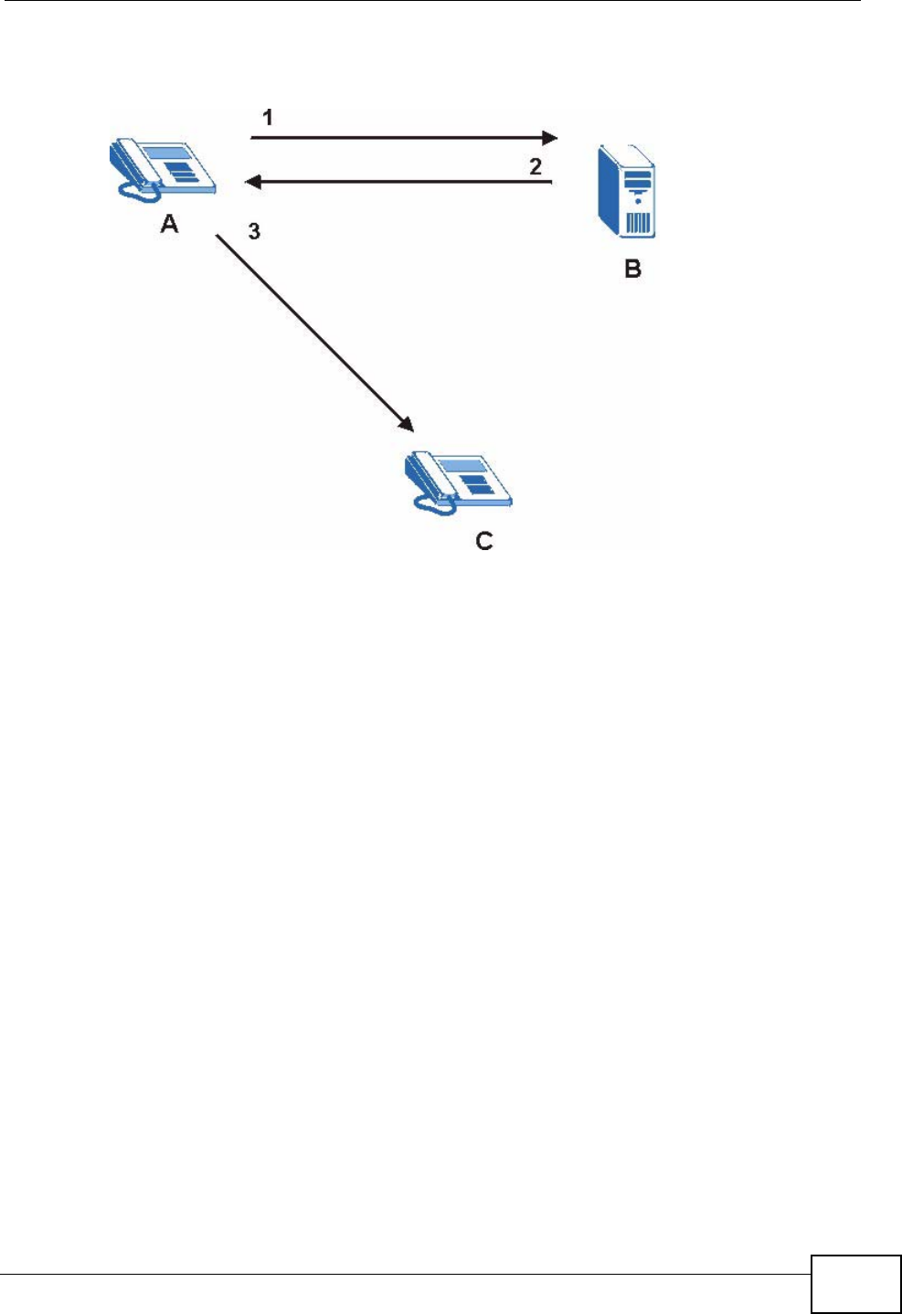
Chapter 17 Voice
NVG2053 User’s Guide 187
3Client device A then sends the call invitation to client device C.
Figure 82 SIP Redirect Server
SIP Register Server
A SIP register server maintains a database of SIP identity-to-IP address (or
domain name) mapping. The register server checks your user name and password
when you register.
RTP
When you make a VoIP call using SIP, the RTP (Real time Transport Protocol) is
used to handle voice data transfer. See RFC 1889 for details on RTP.
Pulse Code Modulation
Pulse Code Modulation (PCM) measures analog signal amplitudes at regular time
intervals and converts them into bits.
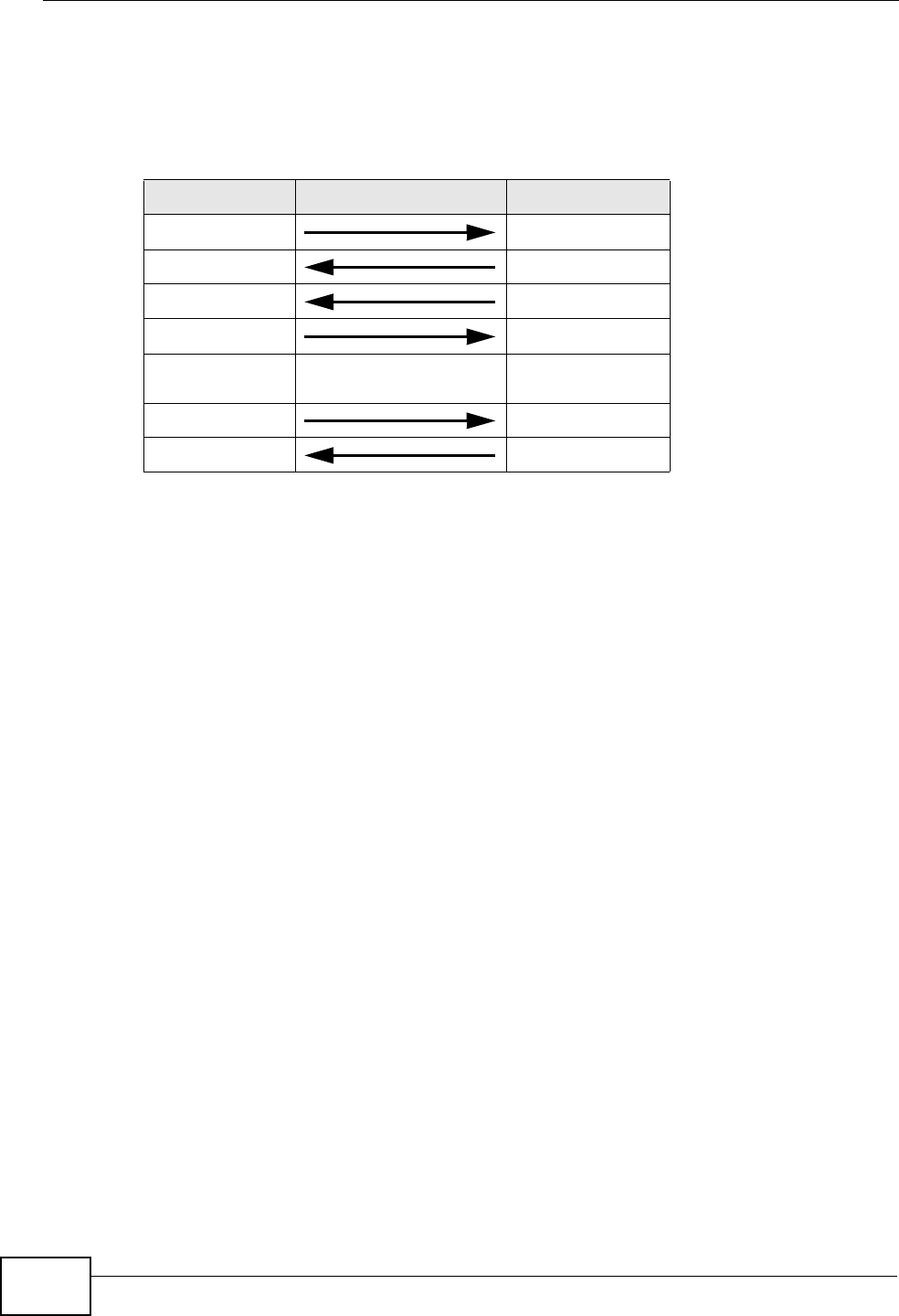
Chapter 17 Voice
NVG2053 User’s Guide
188
SIP Call Progression
The following figure displays the basic steps in the setup and tear down of a SIP
call. A calls B.
1A sends a SIP INVITE request to B. This message is an invitation for B to
participate in a SIP telephone call.
2B sends a response indicating that the telephone is ringing.
3B sends an OK response after the call is answered.
4A then sends an ACK message to acknowledge that B has answered the call.
5Now A and B exchange voice media (talk).
6After talking, A hangs up and sends a BYE request.
7B replies with an OK response confirming receipt of the BYE request and the call is
terminated.
SIP Call Progression Through Proxy Servers
Usually, the SIP UAC sets up a phone call by sending a request to the SIP proxy
server. Then, the proxy server looks up the destination to which the call should be
forwarded (according to the URI requested by the SIP UAC). The request may be
forwarded to more than one proxy server before arriving at its destination.
The response to the request goes to all the proxy servers through which the
request passed, in reverse sequence. Once the session is set up, session traffic is
sent between the UAs directly, bypassing all the proxy servers in between.
Table 64 SIP Call Progression
A B
1. INVITE
2. Ringing
3. OK
4. ACK
5.Dialogue (voice
traffic)
6. BYE
7. OK
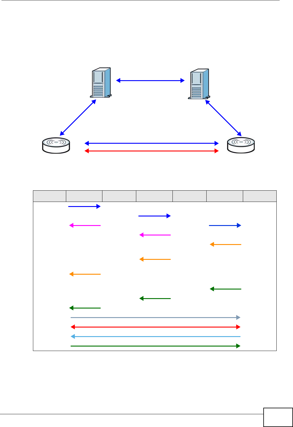
Chapter 17 Voice
NVG2053 User’s Guide 189
The following figure shows the SIP and session traffic flow between the user
agents (UA 1 and UA 2) and the proxy servers (this example shows two proxy
servers, PROXY 1 and PROXY 2).
Figure 83 SIP Call Through Proxy Servers
The following table shows the SIP call progression.
1User Agent 1 sends a SIP INVITE request to Proxy 1. This message is an
invitation to User Agent 2 to participate in a SIP telephone call. Proxy 1 sends a
response indicating that it is trying to complete the request.
Table 65 SIP Call Progression
UA 1 PROXY 1 PROXY 2 UA 2
Invite
Invite
100 Trying Invite
100 Trying
180
Ringing
180
Ringing
180
Ringing
200 OK
200 OK
200 OK
ACK
RTP RTP
BYE
200 OK
UA 1 UA 2
PROXY 1 PROXY 2
SIP
SIP
SIP
SIP & RTP

Chapter 17 Voice
NVG2053 User’s Guide
190
2Proxy 1 sends a SIP INVITE request to Proxy 2. Proxy 2 sends a response
indicating that it is trying to complete the request.
3Proxy 2 sends a SIP INVITE request to User Agent 2.
4User Agent 2 sends a response back to Proxy 2 indicating that the phone is
ringing. The response is relayed back to User Agent 1 via Proxy 1.
5User Agent 2 sends an OK response to Proxy 2 after the call is answered. This is
also relayed back to User Agent 1 via Proxy 1.
6User Agent 1 and User Agent 2 exchange RTP packets containing voice data
directly, without involving the proxies.
7When User Agent 2 hangs up, he sends a BYE request.
8User Agent 1 replies with an OK response confirming receipt of the BYE request,
and the call is terminated.
Voice Coding
A codec (coder/decoder) codes analog voice signals into digital signals and
decodes the digital signals back into analog voice signals. The NVG2053 supports
the following codecs.
• G.711 is a Pulse Code Modulation (PCM) waveform codec. PCM measures analog
signal amplitudes at regular time intervals and converts them into digital
samples. G.711 provides very good sound quality but requires 64 kbps of
bandwidth.
• G.726 is an Adaptive Differential PCM (ADPCM) waveform codec that uses a
lower bitrate than standard PCM conversion. ADPCM converts analog audio into
digital signals based on the difference between each audio sample and a
prediction based on previous samples. The more similar the audio sample is to
the prediction, the less space needed to describe it. G.726 operates at 16, 24,
32 or 40 kbps.
• G.729 is an Analysis-by-Synthesis (AbS) hybrid waveform codec that uses a
filter based on information about how the human vocal tract produces sounds.
G.729 provides good sound quality and reduces the required bandwidth to 8
kbps.
Voice Activity Detection/Silence Suppression
Voice Activity Detection (VAD) detects whether or not speech is present. This lets
the NVG2053 reduce the bandwidth that a call uses by not transmitting “silent
packets” when you are not speaking.

Chapter 17 Voice
NVG2053 User’s Guide 191
Comfort Noise Generation
When using VAD, the NVG2053 generates comfort noise when the other party is
not speaking. The comfort noise lets you know that the line is still connected as
total silence could easily be mistaken for a lost connection.
Echo Cancellation
G.168 is an ITU-T standard for eliminating the echo caused by the sound of your
voice reverberating in the telephone receiver while you talk.
MWI (Message Waiting Indication)
Enable Message Waiting Indication (MWI) enables your phone to give you a
message–waiting (beeping) dial tone when you have a voice message(s). Your
VoIP service provider must have a messaging system that sends message waiting
status SIP packets as defined in RFC 3842.
17.9.1 Quality of Service (QoS)
Quality of Service (QoS) refers to both a network's ability to deliver data with
minimum delay, and the networking methods used to provide bandwidth for real-
time multimedia applications.
Type of Service (ToS)
Network traffic can be classified by setting the ToS (Type of Service) values at the
data source (for example, at the NVG2053) so a server can decide the best
method of delivery, that is the least cost, fastest route and so on.
DiffServ
DiffServ is a class of service (CoS) model that marks packets so that they receive
specific per-hop treatment at DiffServ-compliant network devices along the route
based on the application types and traffic flow. Packets are marked with DiffServ
Code Points (DSCP) indicating the level of service desired. This allows the
intermediary DiffServ-compliant network devices to handle the packets differently
depending on the code points without the need to negotiate paths or remember
state information for every flow. In addition, applications do not have to request a
particular service or give advanced notice of where the traffic is going.3
3. The NVG2053 does not support DiffServ at the time of writing.

Chapter 17 Voice
NVG2053 User’s Guide
192
DSCP and Per-Hop Behavior
DiffServ defines a new DS (Differentiated Services) field to replace the Type of
Service (TOS) field in the IP header. The DS field contains a 2-bit unused field and
a 6-bit DSCP field which can define up to 64 service levels. The following figure
illustrates the DS field.
DSCP is backward compatible with the three precedence bits in the ToS octet so
that non-DiffServ compliant, ToS-enabled network device will not conflict with the
DSCP mapping.
Figure 84 DiffServ: Differentiated Service Field
The DSCP value determines the forwarding behavior, the PHB (Per-Hop Behavior),
that each packet gets across the DiffServ network. Based on the marking rule,
different kinds of traffic can be marked for different priorities of forwarding.
Resources can then be allocated according to the DSCP values and the configured
policies.
17.9.2 Phone Services Overview
Supplementary services such as call hold, call waiting, and call transfer. are
generally available from your VoIP service provider. The NVG2053 supports the
following services:
• Call Hold
• Call Waiting
• Making a Second Call
• Call Transfer
• Call Forwarding
• Three-Way Conference
•Internal Calls
• Call Park and Pickup
•Do not Disturb
Note: To take full advantage of the supplementary phone services available through
the NVG2053's phone ports, you may need to subscribe to the services from
your VoIP service provider.
DSCP
(6-bit)
Unused
(2-bit)
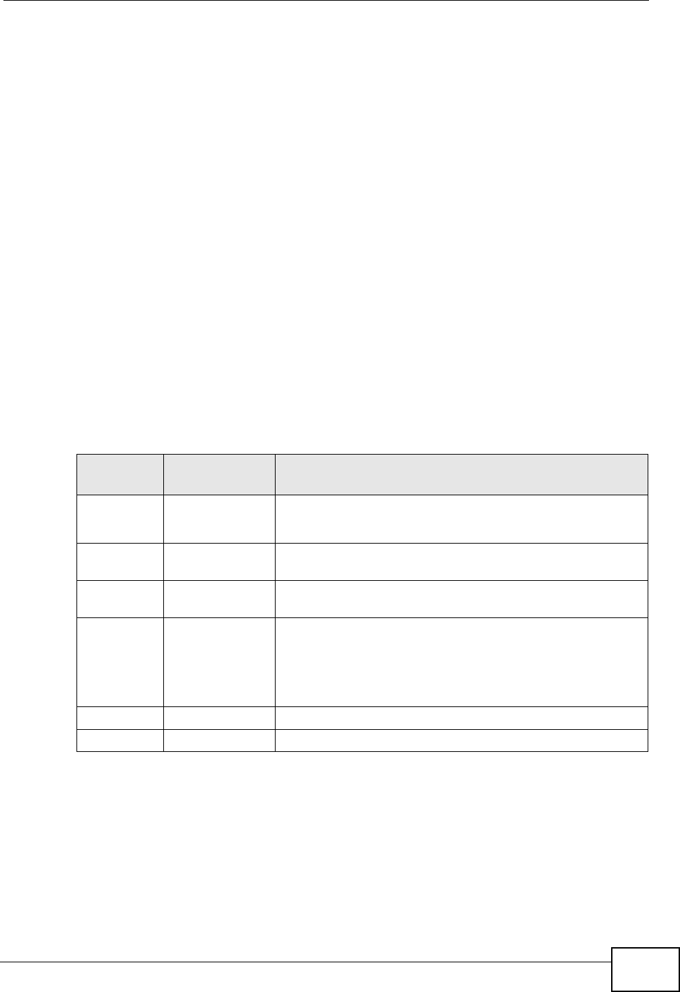
Chapter 17 Voice
NVG2053 User’s Guide 193
17.9.2.1 The Flash Key
Flashing means to press the hook for a short period of time (a few hundred
milliseconds) before releasing it. On newer telephones, there should be a "flash"
key (button) that generates the signal electronically. If the flash key is not
available, you can tap (press and immediately release) the hook by hand to
achieve the same effect. However, using the flash key is preferred since the timing
is much more precise. With manual tapping, if the duration is too long, it may be
interpreted as hanging up by the NVG2053.
You can invoke all the supplementary services by using the flash key.
17.9.2.2 Europe Type Supplementary Phone Services
This section describes how to use supplementary phone services with the Europe
Type Call Service Mode. Commands for supplementary services are listed in the
table below.
After pressing the flash key, if you do not issue the sub-command before the
default sub-command timeout (2 seconds) expires or issue an invalid sub-
command, the current operation will be aborted.
European Call Hold
Call hold allows you to put a call (A) on hold by pressing the flash key.
If you have another call, press the flash key and then “2” to switch back and forth
between caller A and B by putting either one on hold.
Table 66 European Flash Key Commands
COMMAND SUB-
COMMAND DESCRIPTION
Flash Put a current call on hold to place a second call.
Switch back to the call (if there is no second call).
Flash 0 Drop the call presently on hold or reject an incoming call
which is waiting for answer.
Flash 1 Disconnect the current phone connection and answer the
incoming call or resume with caller presently on hold.
Flash 2 1. Switch back and forth between two calls.
2. Put a current call on hold to answer an incoming call.
3. Separate the current three-way conference call into
two individual calls (one is on-line, the other is on hold).
Flash 3 Create three-way conference connection.
Flash *98# Transfer the call to another phone.

Chapter 17 Voice
NVG2053 User’s Guide
194
Press the flash key and then “0” to disconnect the call presently on hold and keep
the current call on line.
Press the flash key and then “1” to disconnect the current call and resume the call
on hold.
If you hang up the phone but a caller is still on hold, there will be a remind ring.
European Call Waiting
This allows you to place a call on hold while you answer another incoming call on
the same telephone (directory) number.
If there is a second call to a telephone number, you will hear a call waiting tone.
Take one of the following actions.
• Reject the second call.
Press the flash key and then press “0”.
• Disconnect the first call and answer the second call.
Either press the flash key and press “1”, or just hang up the phone and then
answer the phone after it rings.
• Put the first call on hold and answer the second call.
Press the flash key and then “2”.
European Call Transfer
Do the following to transfer an incoming call (that you have answered) to another
phone.
1Press the flash key to put the caller on hold.
2When you hear the dial tone, dial “*98#” followed by the number to which you
want to transfer the call.
3After you hear the ring signal or the second party answers it, hang up the phone.
European Three-Way Conference
Use the following steps to make three-way conference calls.
1When you are on the phone talking to someone, press the flash key to put the
caller on hold and get a dial tone.
2Dial a phone number directly to make another call.
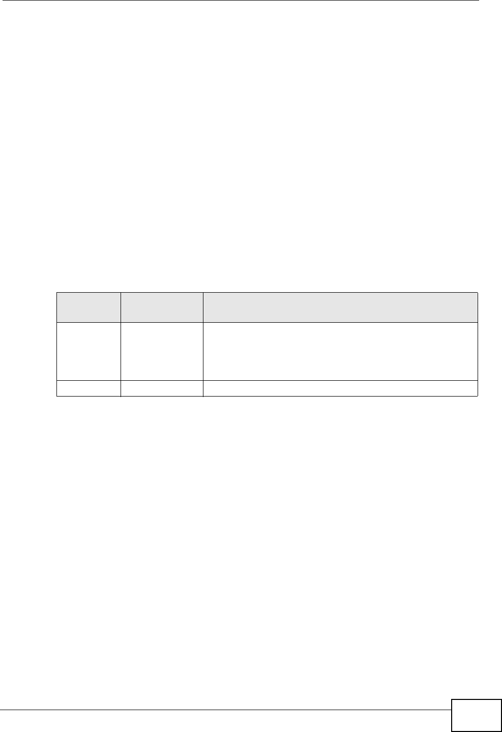
Chapter 17 Voice
NVG2053 User’s Guide 195
3When the second call is answered, press the flash key and press “3” to create a
three-way conversation.
4Hang up the phone to drop the connection.
5If you want to separate the activated three-way conference into two individual
connections (one is on-line, the other is on hold), press the flash key and press
“2”.
17.9.2.3 USA Type Supplementary Services
This section describes how to use supplementary phone services with the USA
Type Call Service Mode. Commands for supplementary services are listed in the
table below.
After pressing the flash key, if you do not issue the sub-command before the
default sub-command timeout (2 seconds) expires or issue an invalid sub-
command, the current operation will be aborted.
USA Call Hold
Call hold allows you to put a call (A) on hold by pressing the flash key.
If you have another call, press the flash key to switch back and forth between
caller A and B by putting either one on hold.
If you hang up the phone but a caller is still on hold, there will be a remind ring.
USA Call Waiting
This allows you to place a call on hold while you answer another incoming call on
the same telephone (directory) number.
If there is a second call to your telephone number, you will hear a call waiting
tone.
Press the flash key to put the first call on hold and answer the second call.
Table 67 USA Flash Key Commands
COMMAND SUB-
COMMAND DESCRIPTION
Flash Put a current call on hold to place a second call. After the
second call is successful, press the flash key again to
have a three-way conference call.
Put a current call on hold to answer an incoming call.
Flash *98# Transfer the call to another phone.

Chapter 17 Voice
NVG2053 User’s Guide
196
USA Call Transfer
Do the following to transfer an incoming call (that you have answered) to another
phone.
1Press the flash key to put the caller on hold.
2When you hear the dial tone, dial “*98#” followed by the number to which you
want to transfer the call.
3After you hear the ring signal or the second party answers it, hang up the phone.
USA Three-Way Conference
Use the following steps to make three-way conference calls.
1When you are on the phone talking to someone (party A), press the flash key to
put the caller on hold and get a dial tone.
2Dial a phone number directly to make another call (to party B).
3When party B answers the second call, press the flash key to create a three-way
conversation.
4Hang up the phone to drop the connection.
5If you want to separate the activated three-way conference into two individual
connections (with party A on-line and party B on hold), press the flash key.
6If you want to go back to the three-way conversation, press the flash key again.
7If you want to separate the activated three-way conference into two individual
connections again, press the flash key. This time the party B is on-line and party A
is on hold.
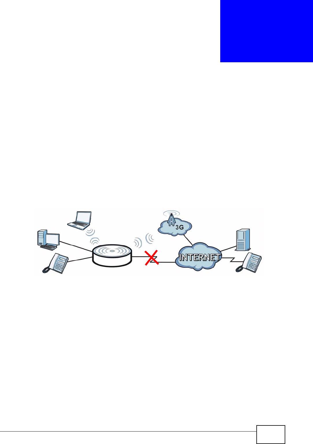
NVG2053 User’s Guide 197
CHAPTER 18
USB Service
18.1 Overview
This chapter discusses the NVG2053’s 3G Connection Setup screens.
3G (third generation) standards for the sending and receiving of voice, video, and
wireless data in a mobile environment.
You can attach a 3G wireless adapter to the USB port and set the NVG2053 to use
this 3G connection as your WAN or a backup when the wired WAN connection fails.
Figure 85 3G WAN Connection
18.1.1 What You Can Do in this Chapter
The 3G Connection Setup screen lets you configure the 3G WAN connection
(Section 18.4 on page 198).
18.2 What You Need to Know
3G
3G (Third Generation) is a digital, packet-switched wireless technology. Bandwidth
usage is optimized as multiple users share the same channel and bandwidth is
only allocated to users when they send data. It allows fast transfer of voice and
non-voice data and provides broadband Internet access to mobile devices.
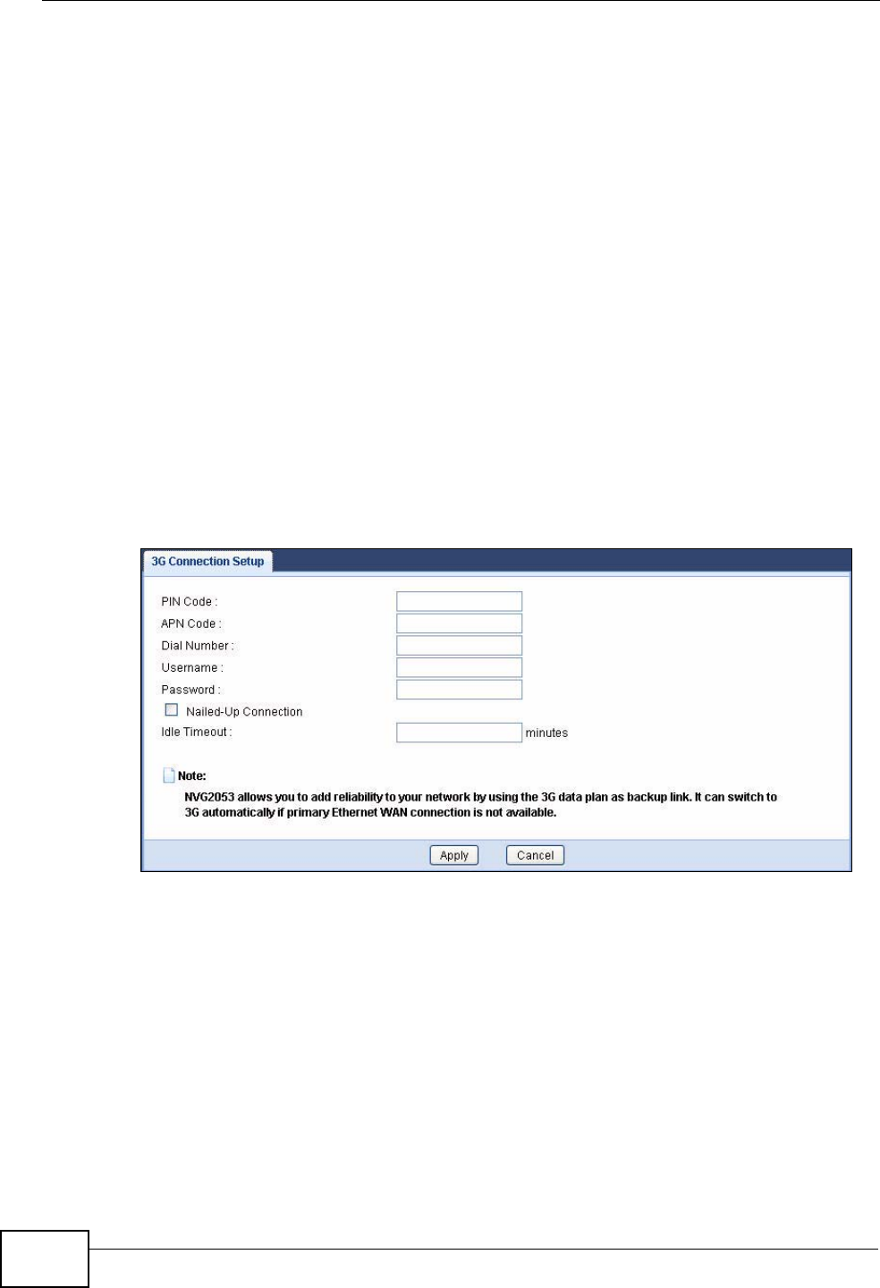
Chapter 18 USB Service
NVG2053 User’s Guide
198
18.3 Before You Begin
For the NVG2053, this type of wireless connection requires a connected 3G-
compatible USB device (see the included Quick Start Guide for installation
information), and a 3G account with your local ISP.
18.4 The 3G Connection Setup Screen
Use this screen to configure your 3G settings. Click Configuration > USB
Service.
At the time of writing, the 3G cards you can use in the NVG2053 are Huawei E169,
Huawei E169G, Huawei E219, D-Link DVM-152 and D-Link DVM-156.
Note: The actual data rate you obtain varies depending the 3G card you use, the
signal strength to the service provider’s base station, and so on.
Figure 86 USB Service > 3G Connection Setup

Chapter 18 USB Service
NVG2053 User’s Guide 199
The following table describes the labels in this screen.
Table 68 USB Service > 3G Connection Setup
LABEL DESCRIPTION
PIN Code A PIN (Personal Identification Number) code is a key to a 3G card.
Without the PIN code, you cannot use the 3G card.
If your ISP enabled PIN code authentication, enter the 4-digit PIN
code (0000 for example) provided by your ISP. If you enter the PIN
code incorrectly, the 3G card may be blocked by your ISP and you
cannot use the account to access the Internet.
If your ISP disabled PIN code authentication, leave this field blank.
APN Code Enter the APN (Access Point Name) provided by your service provider.
Connections with different APNs may provide different services (such
as Internet access or MMS (Multi-Media Messaging Service)) and
charge method.
You can enter up to 31 ASCII printable characters. Spaces are
allowed.
Dial Number Enter the phone number (dial string) used to dial up a connection to
your service provider’s base station. Your ISP should provide the
phone number.
For example, *99# is the dial string to establish a GPRS or 3G
connection in Taiwan.
Username Type the user name (of up to 70 ASCII printable characters) given to
you by your service provider.
Password Type the password (of up to 70 ASCII printable characters) associated
with the user name above.
Nailed-Up
Connection Select the check box if you do not want the connection to time out.
Clear the check box if you do not want the connection up all the time
and specify an idle time-out in the Idle Timeout field.
Idle Timeout This value specifies the time in minutes that elapses before the
NVG2053 automatically disconnects from the ISP.
0 means the Internet session will not timeout.
Apply Click Apply to save your changes back to the NVG2053.
Cancel Click Cancel to return to the previous configuration.

Chapter 18 USB Service
NVG2053 User’s Guide
200