ZyXEL Communications NVG2053 Wireless N Gigabit VoIP Gateway User Manual ZyBook2
ZyXEL Communications Corporation Wireless N Gigabit VoIP Gateway ZyBook2
UserManual.wiki
>
ZyXEL Communications
>
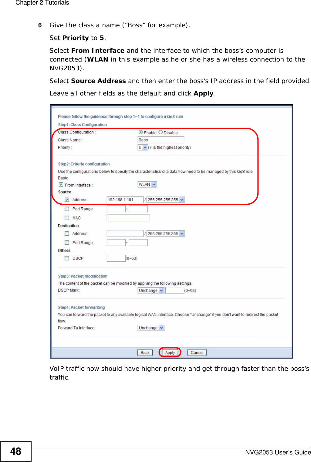
NVG2053 User Manual
>
User's manual-1
Contents
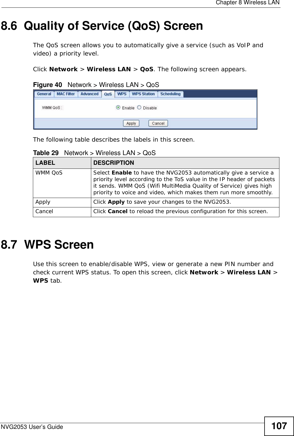
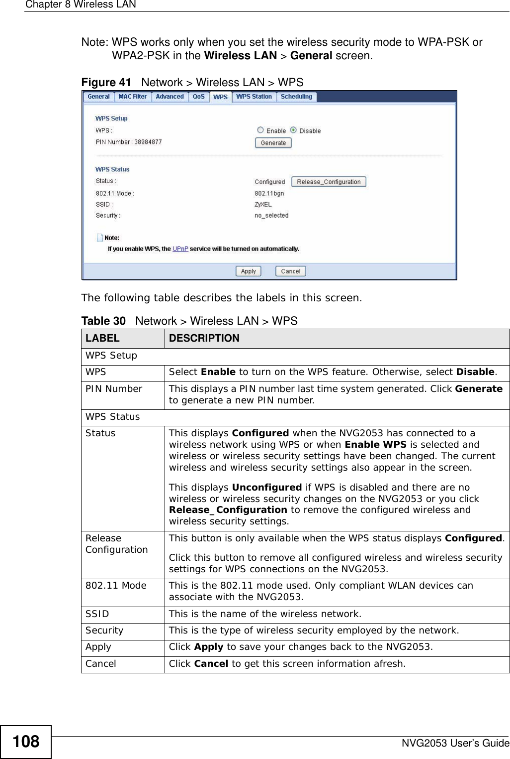
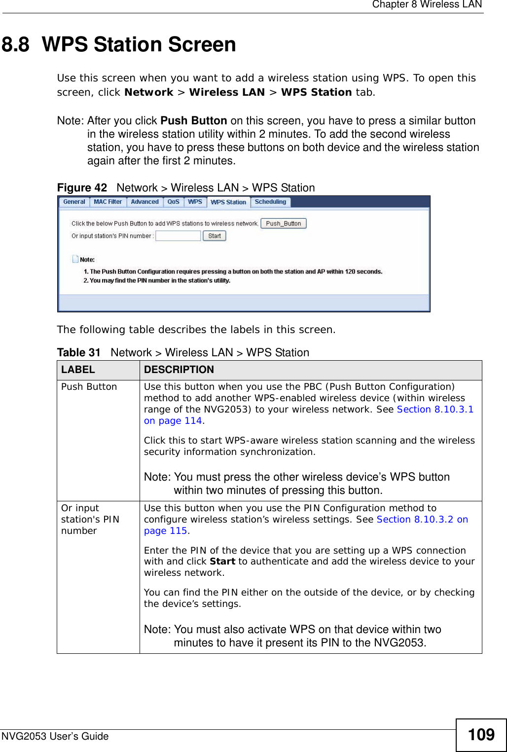
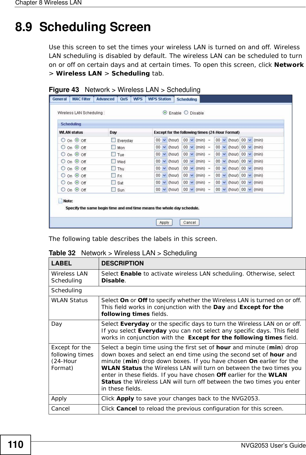
1.
User's manual-1
2.
User's manual-2
User's manual-1
Navigation menu
Upload a User Manual
Namespaces
Wiki Guide
HTML
PDF
Info
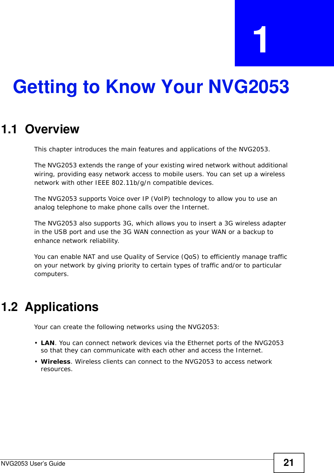
Views
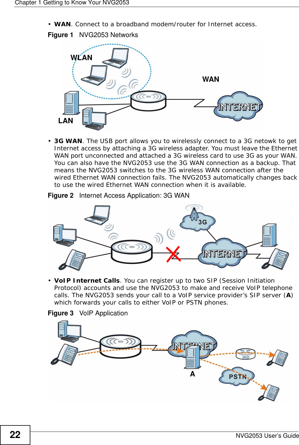
User Manual
Discussion / Help
Navigation
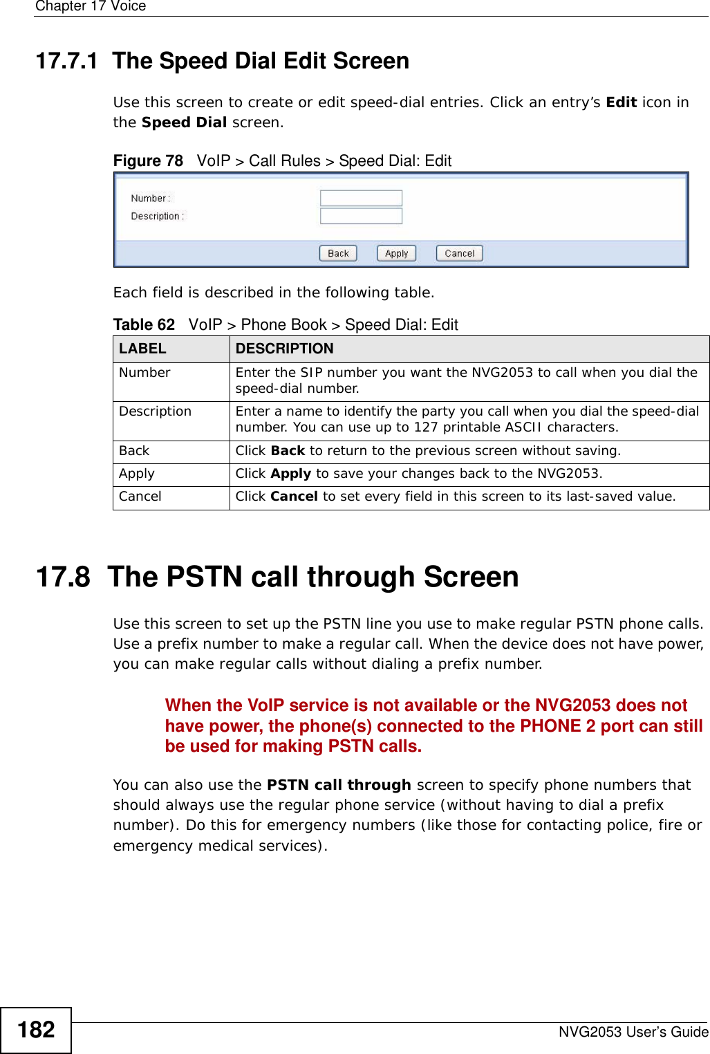
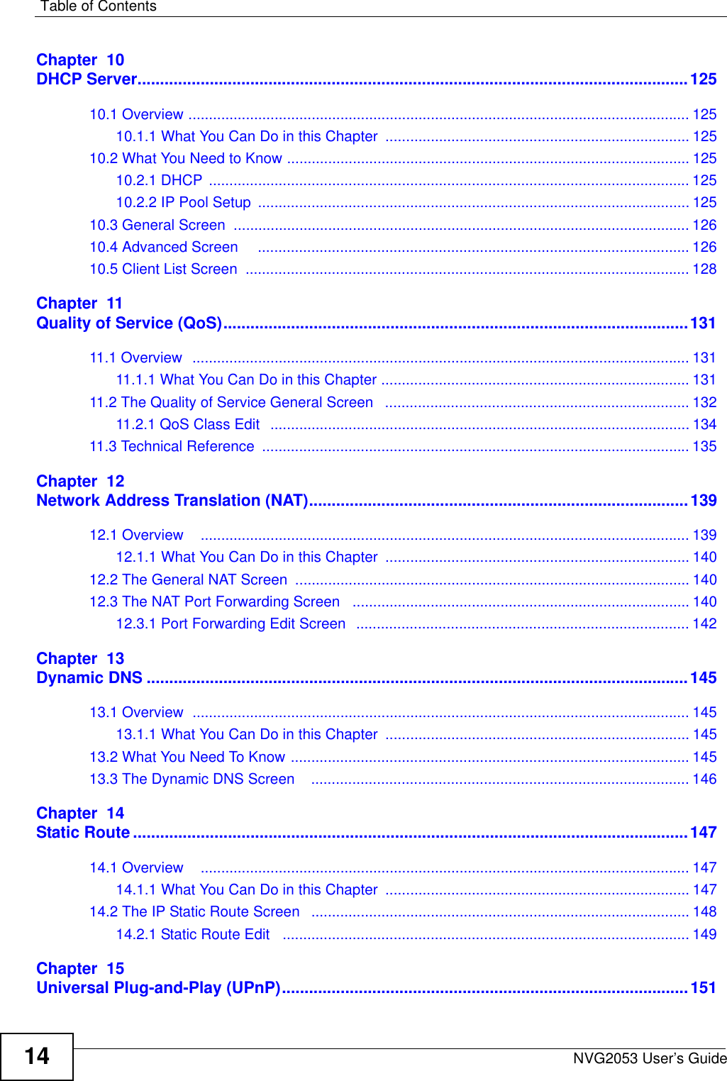
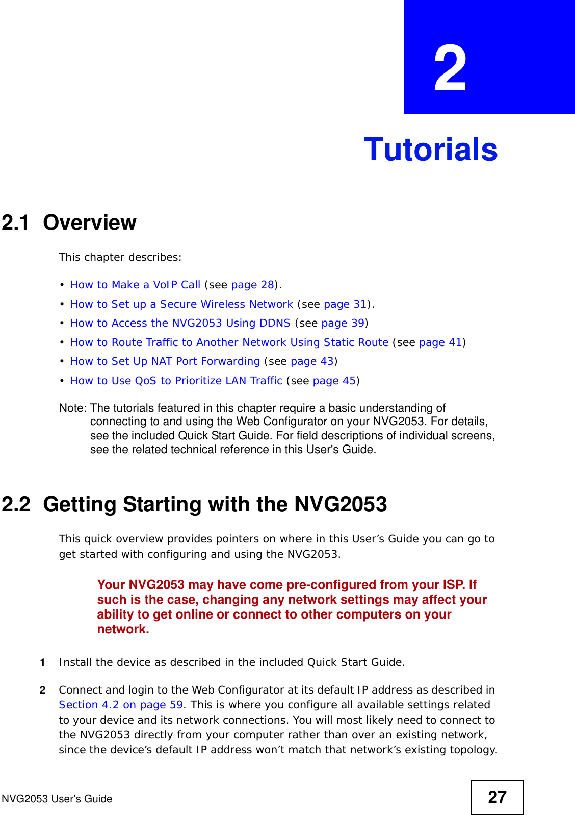
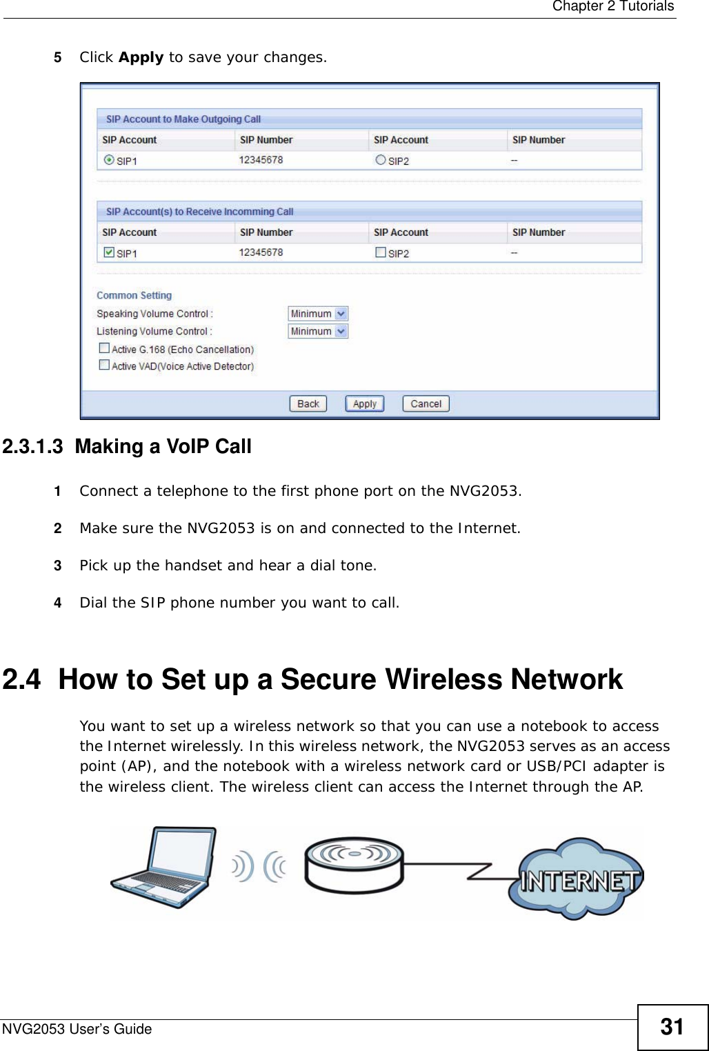
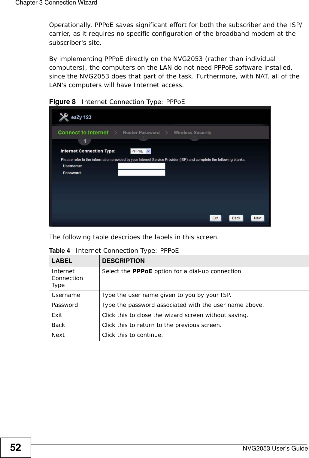
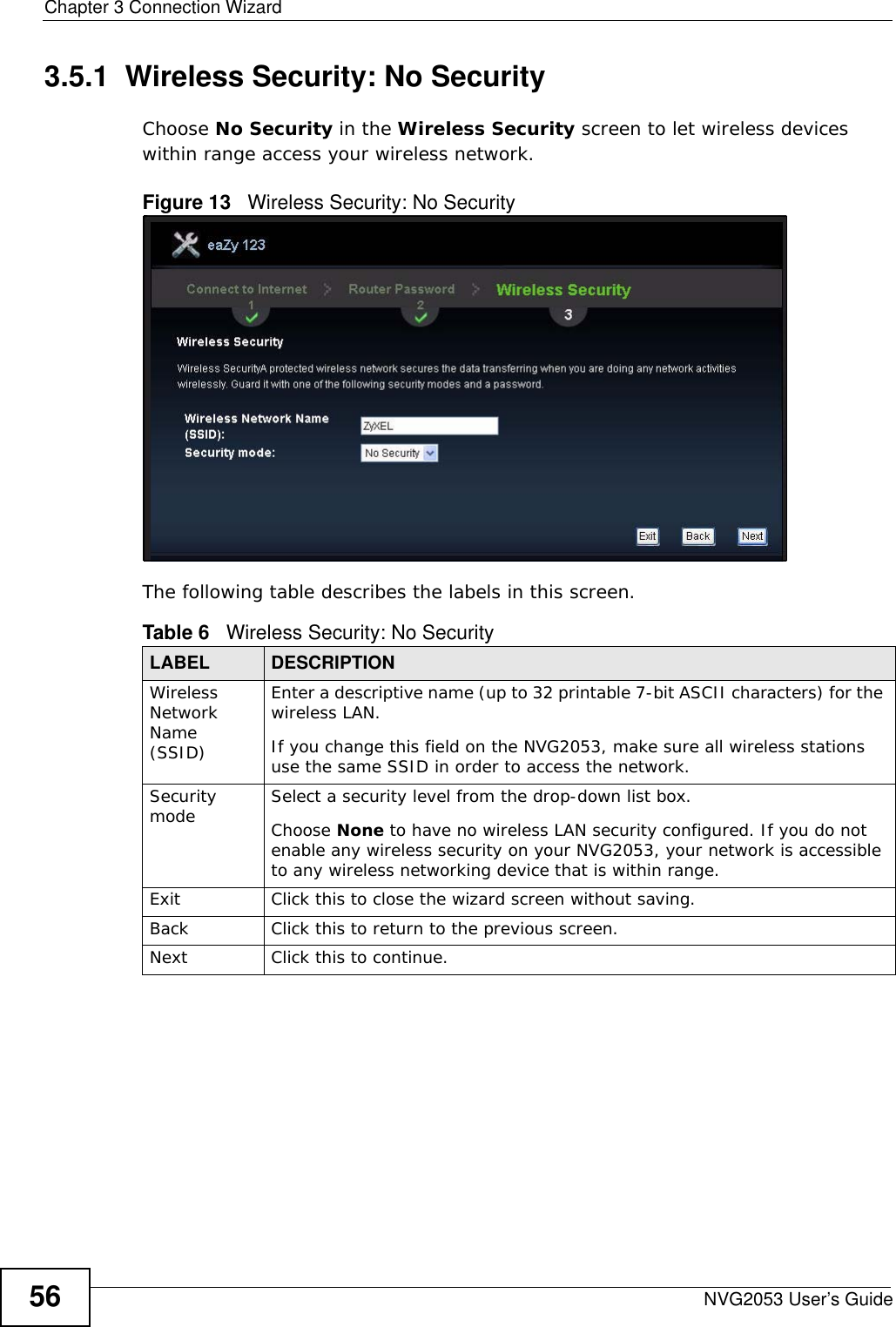
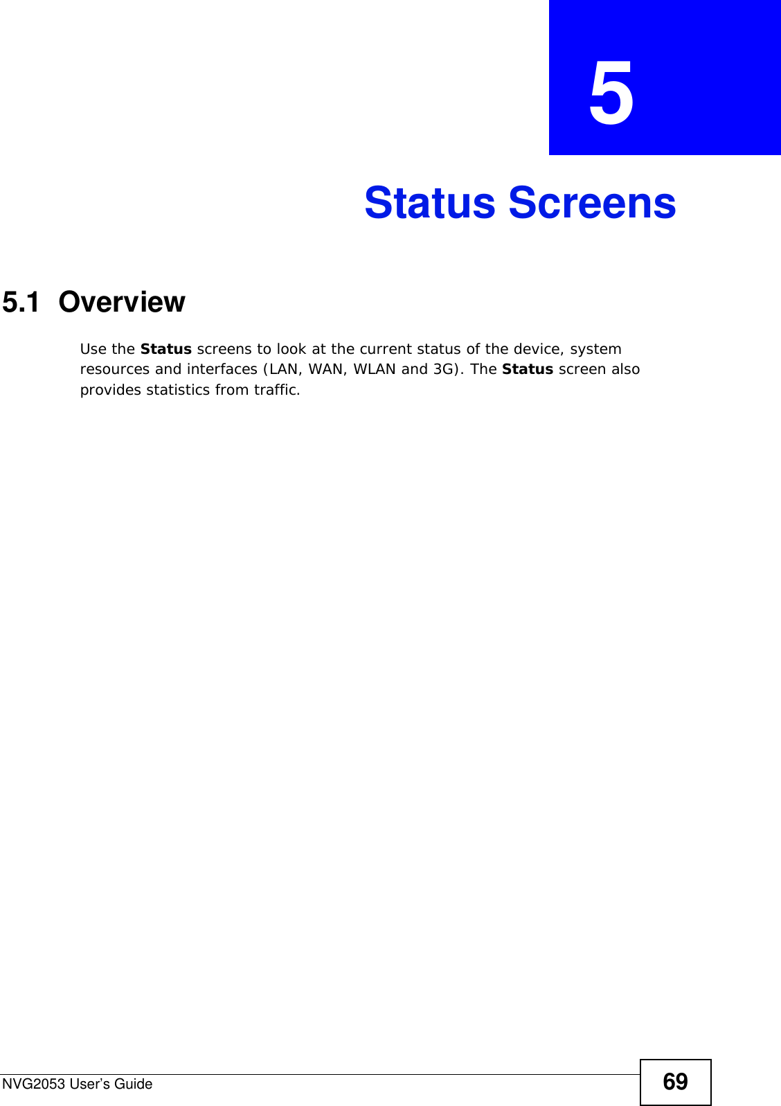
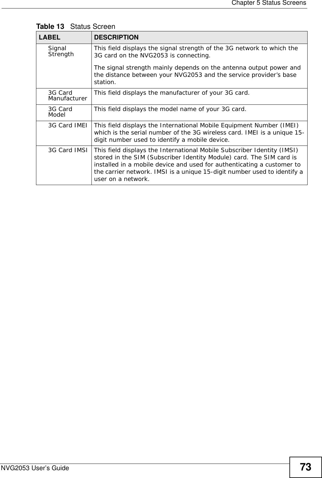
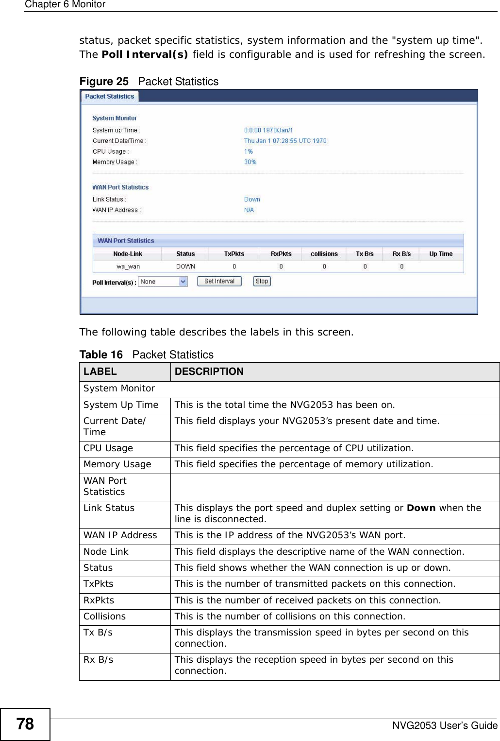
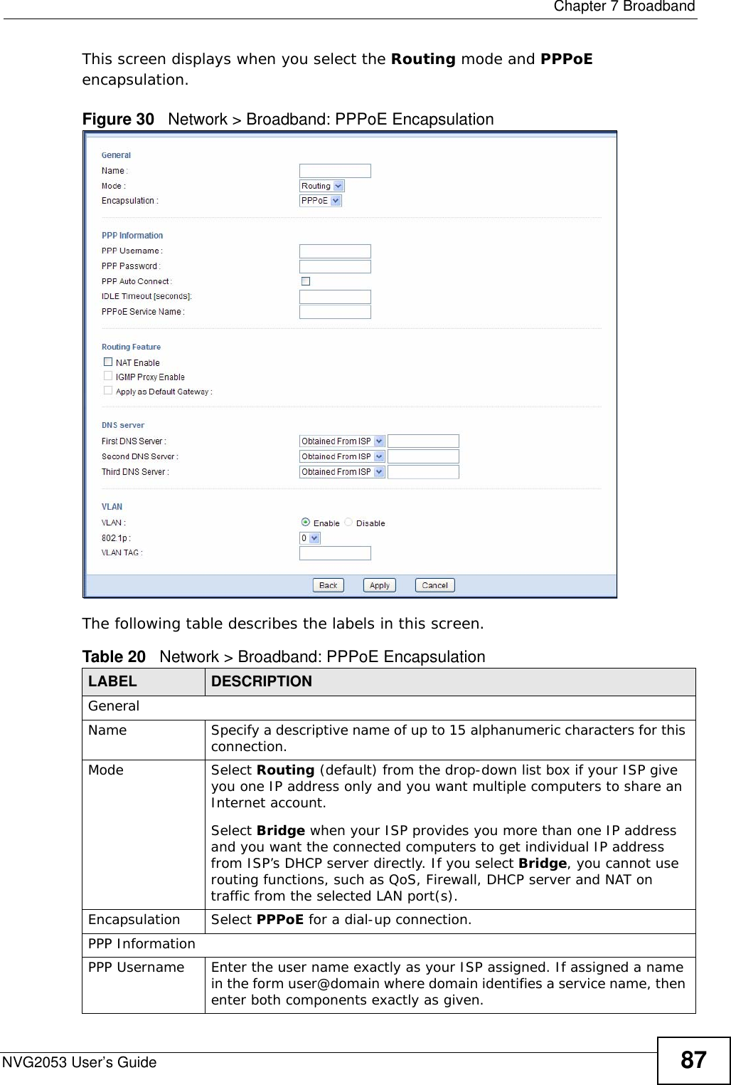
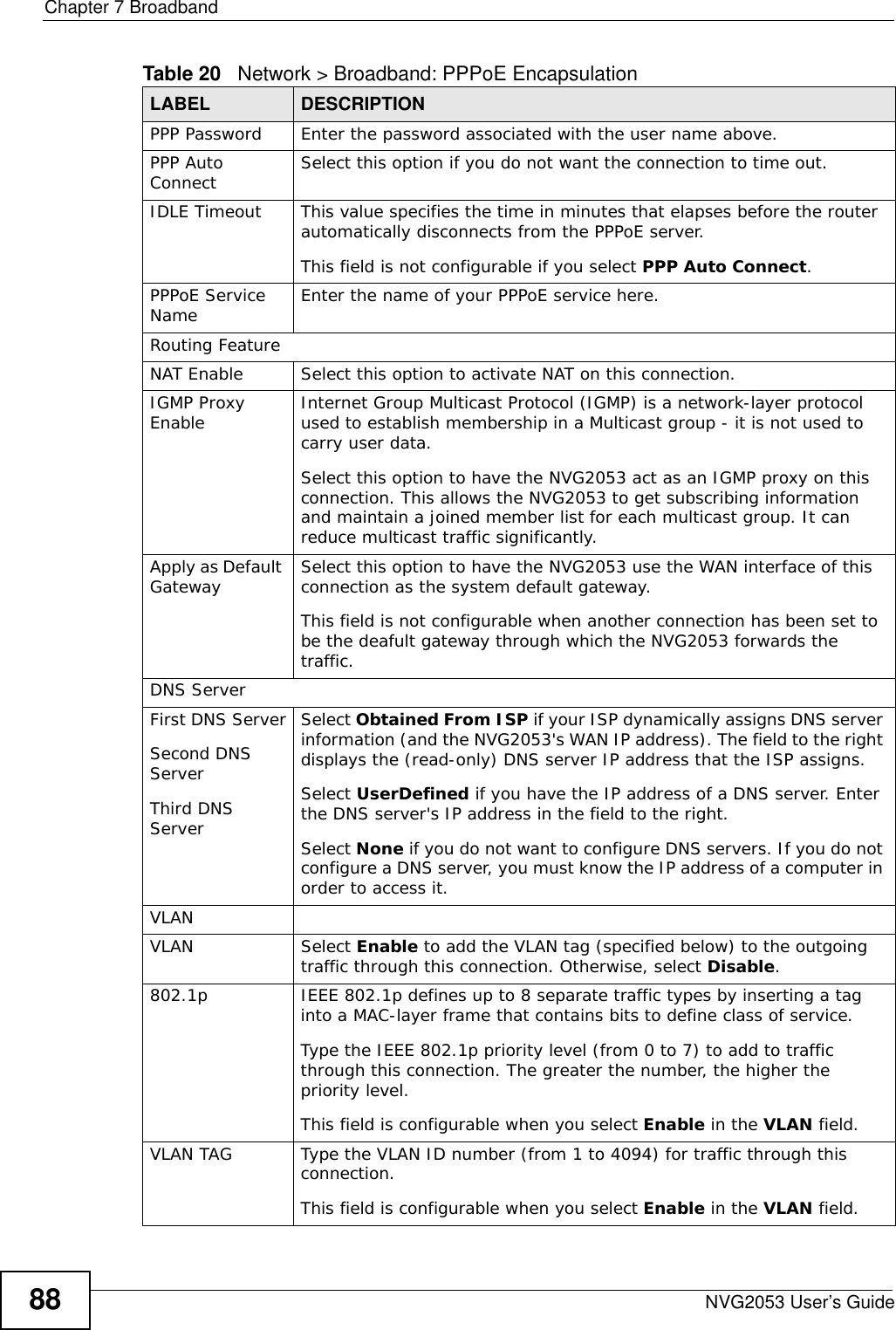
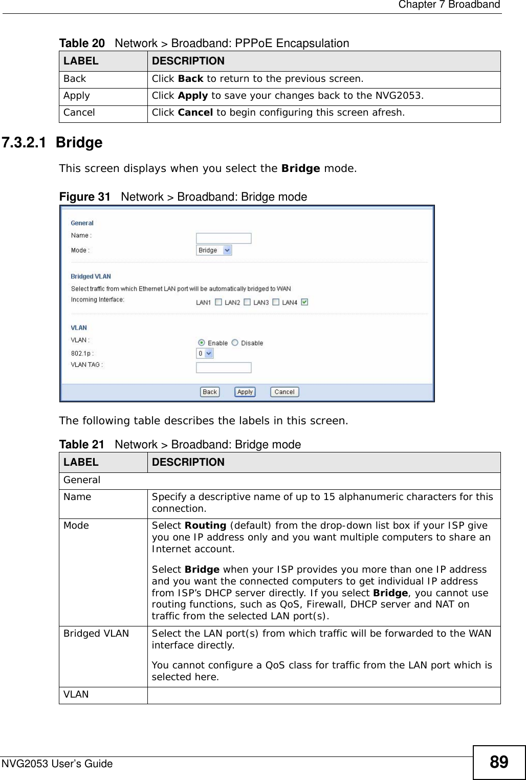
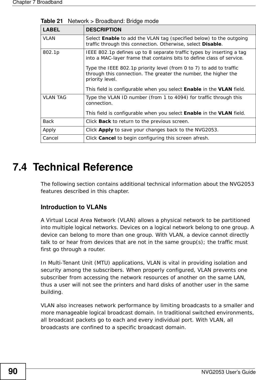
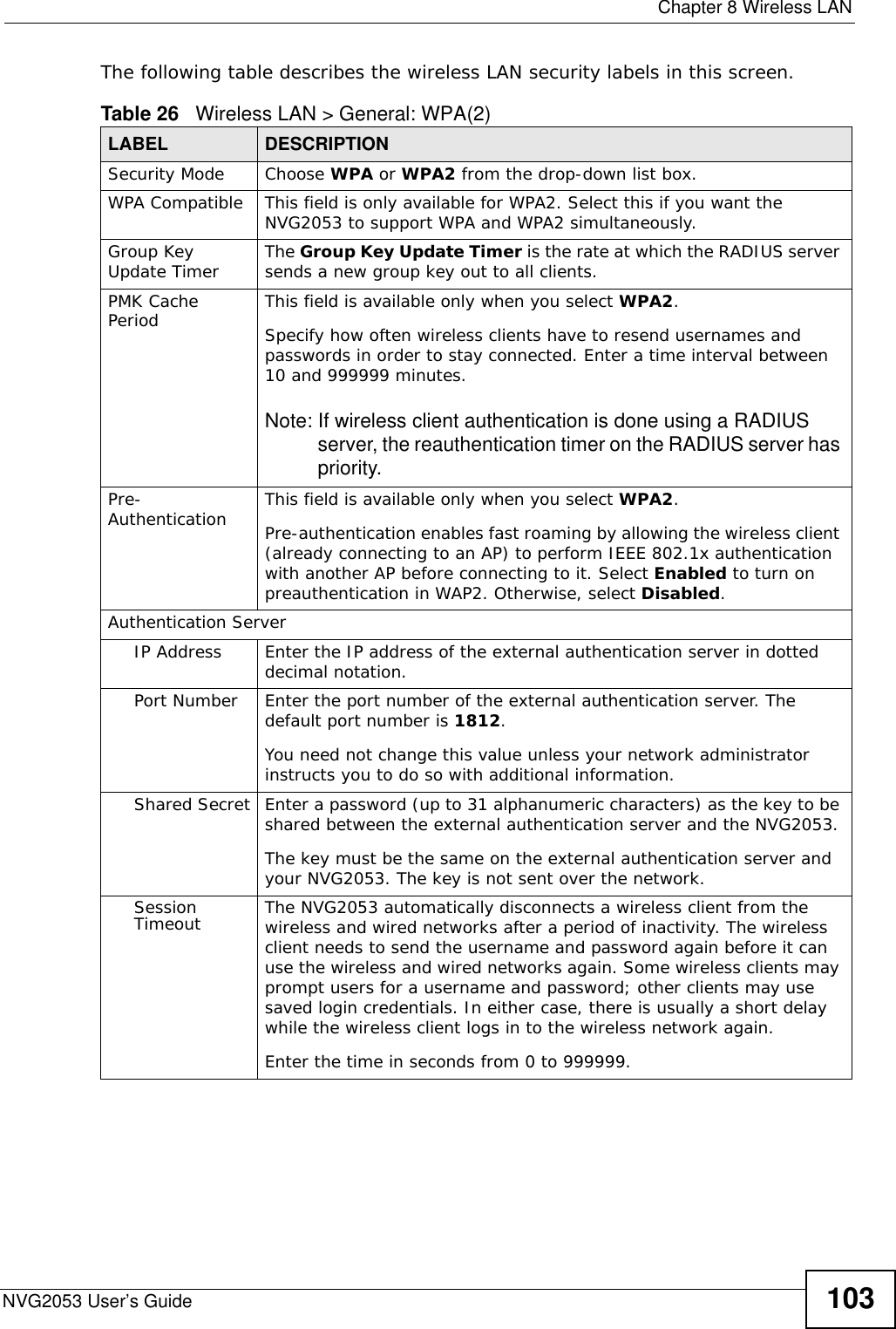
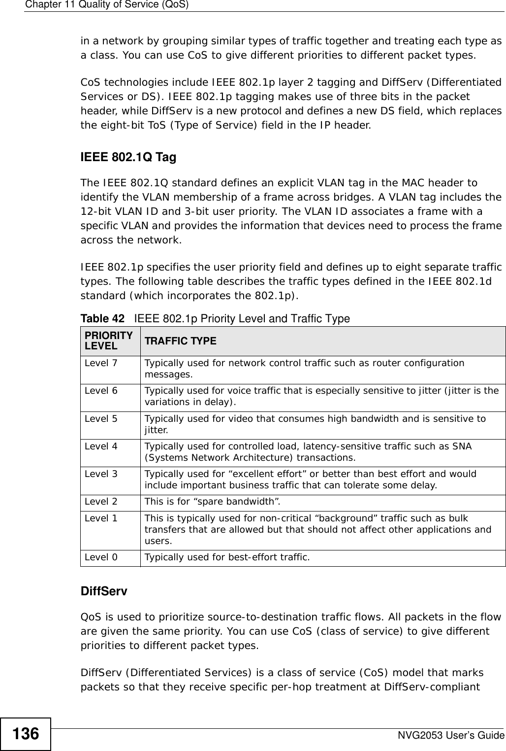
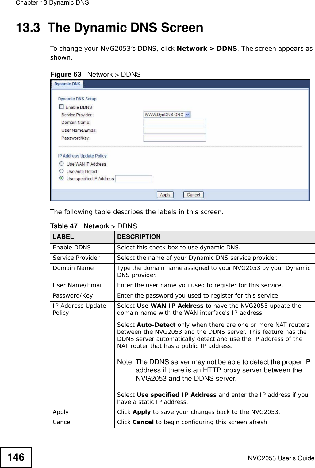
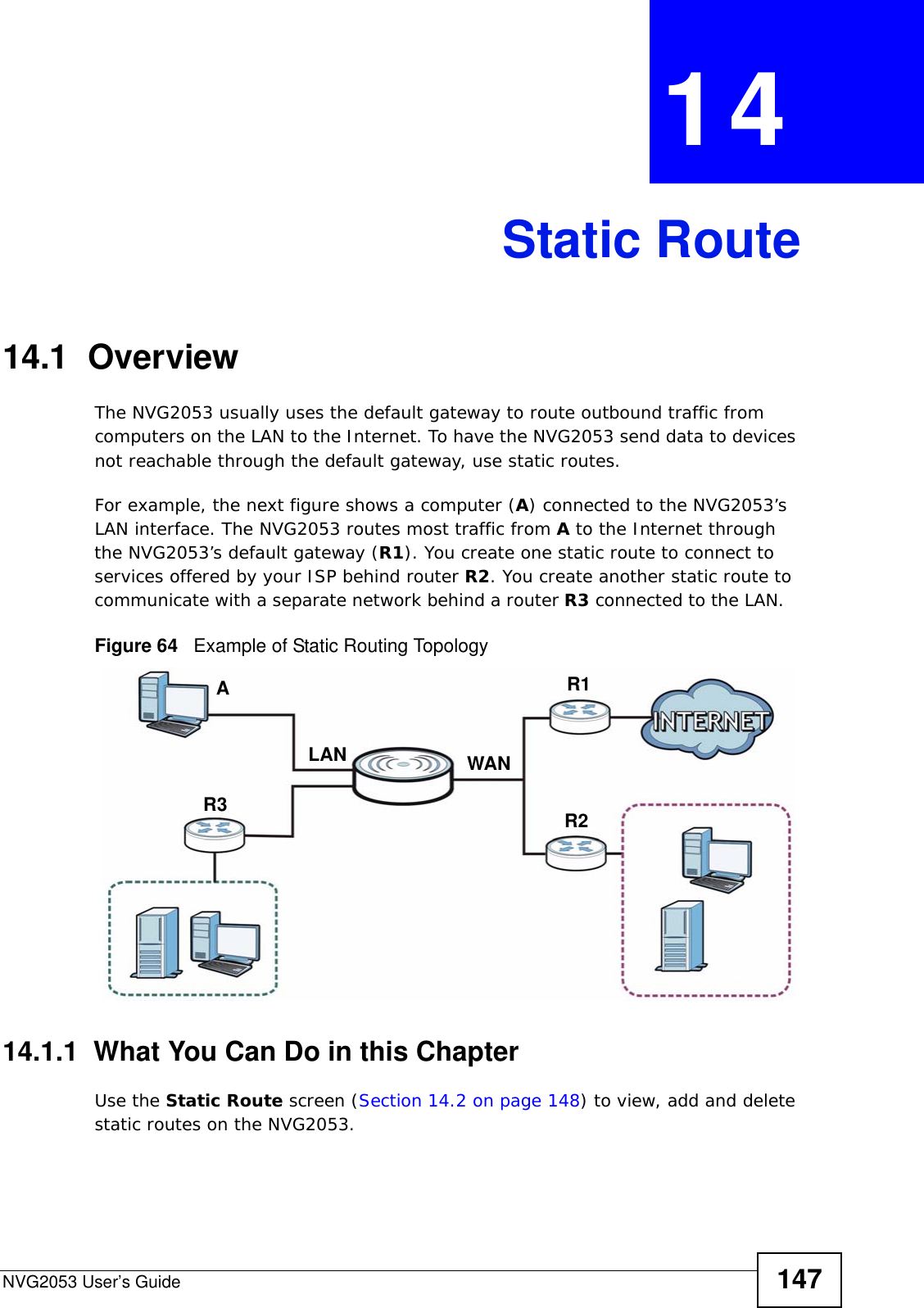
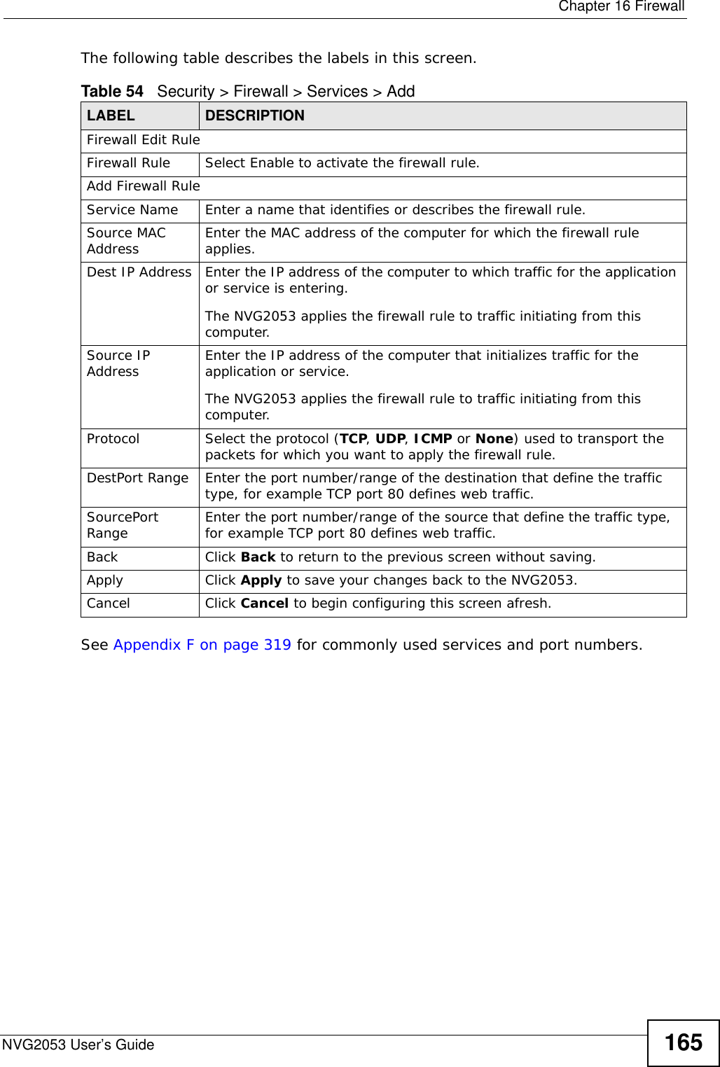
![Document ConventionsNVG2053 User’s Guide 5Document ConventionsWarnings and NotesThese are how warnings and notes are shown in this User’s Guide. Warnings tell you about things that could harm you or your device.Note: Notes tell you other important information (for example, other things you may need to configure or helpful tips) or recommendations.Syntax Conventions• The NVG2053 may be referred to as the “NVG2053”, the “device”, the “product” or the “system” in this User’s Guide.• Product labels, screen names, field labels and field choices are all in bold font.• A key stroke is denoted by square brackets and uppercase text, for example, [ENTER] means the “enter” or “return” key on your keyboard.• “Enter” means for you to type one or more characters and then press the [ENTER] key. “Select” or “choose” means for you to use one of the predefined choices.• A right angle bracket ( > ) within a screen name denotes a mouse click. For example, Maintenance > Log > Log Setting means you first click Maintenance in the navigation panel, then the Log sub menu and finally the Log Setting tab to get to that screen.• Units of measurement may denote the “metric” value or the “scientific” value. For example, “k” for kilo may denote “1000” or “1024”, “M” for mega may denote “1000000” or “1048576” and so on.• “e.g.,” is a shorthand for “for instance”, and “i.e.,” means “that is” or “in other words”.Icons Used in FiguresFigures in this User’s Guide use the following generic icons. The NVG2053 icon is not an exact representation of your NVG2053. Graphics in this book may differ slightly from the product due to differences in operating systems, operating system versions, or if you installed updated](https://usermanual.wiki/ZyXEL-Communications/NVG2053.User-s-manual-1/User-Guide-1439016-Page-5.png)
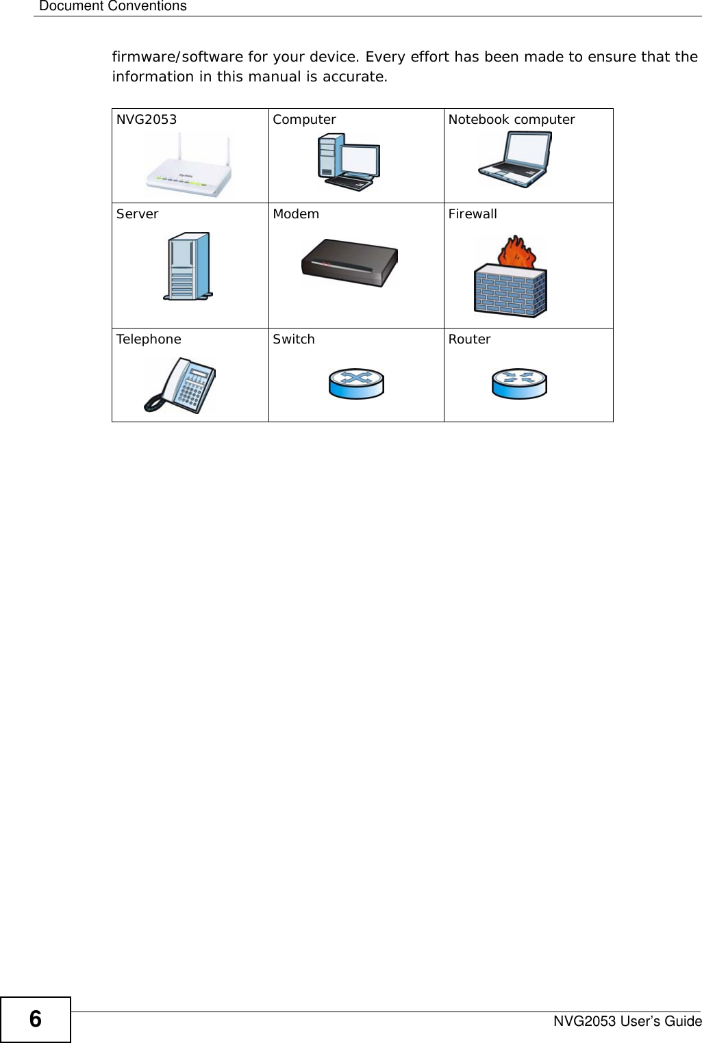

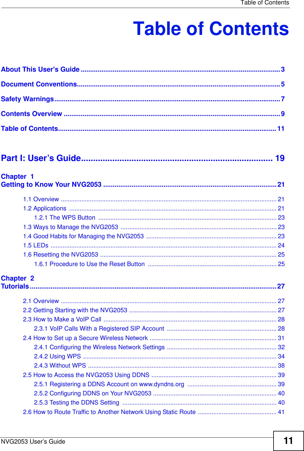
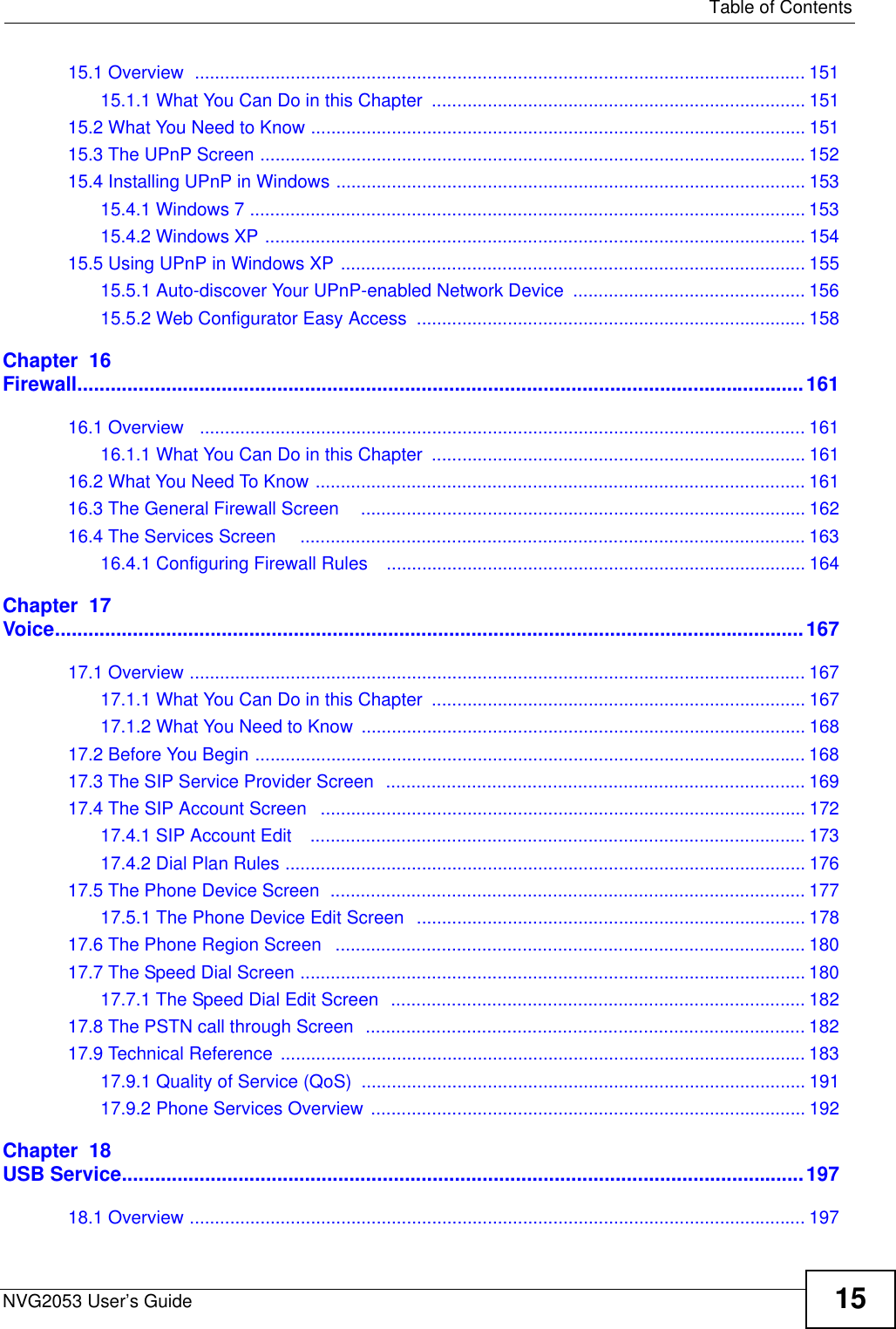

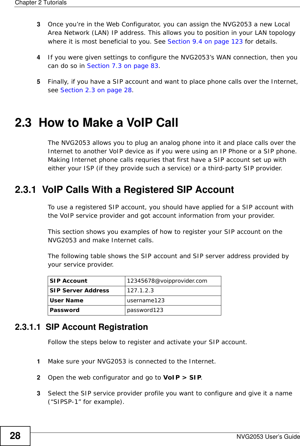
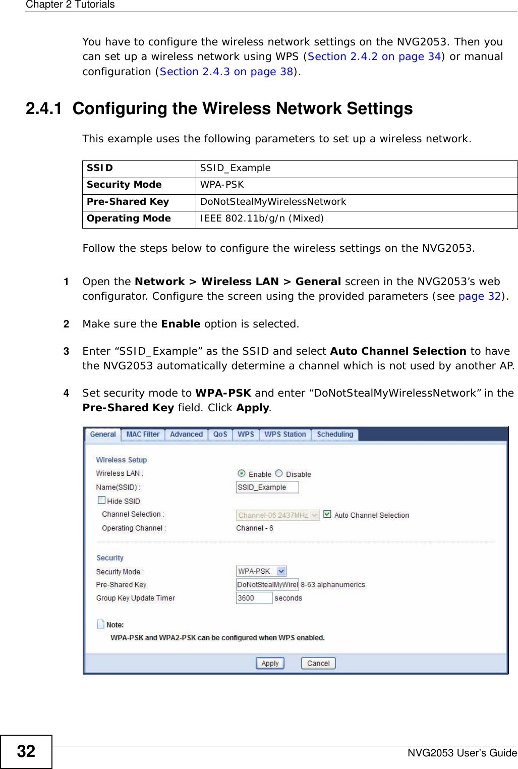
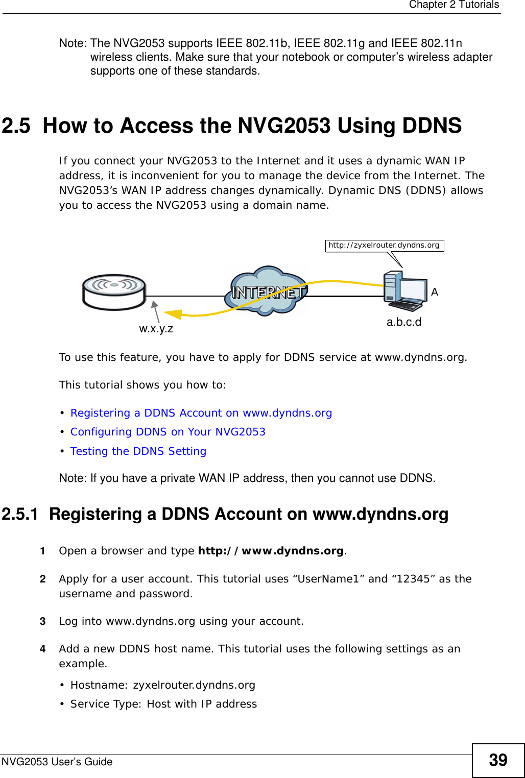
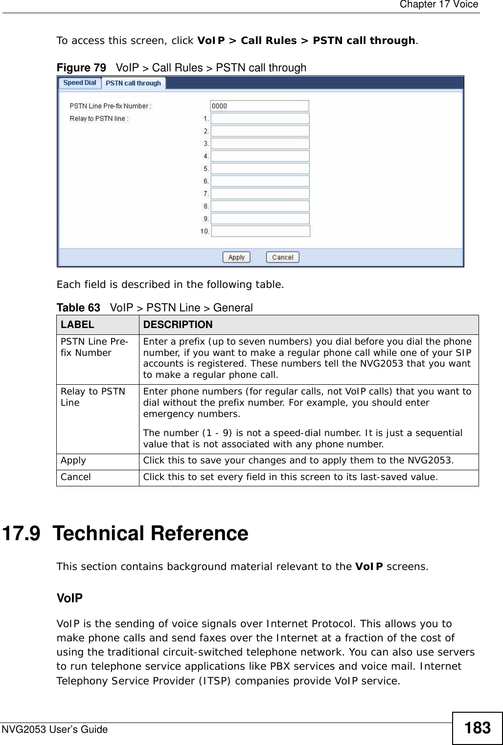
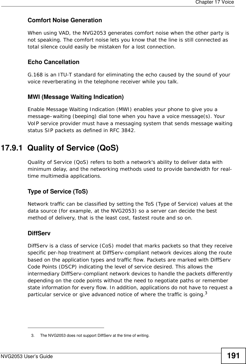
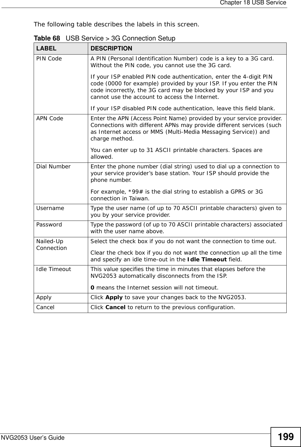
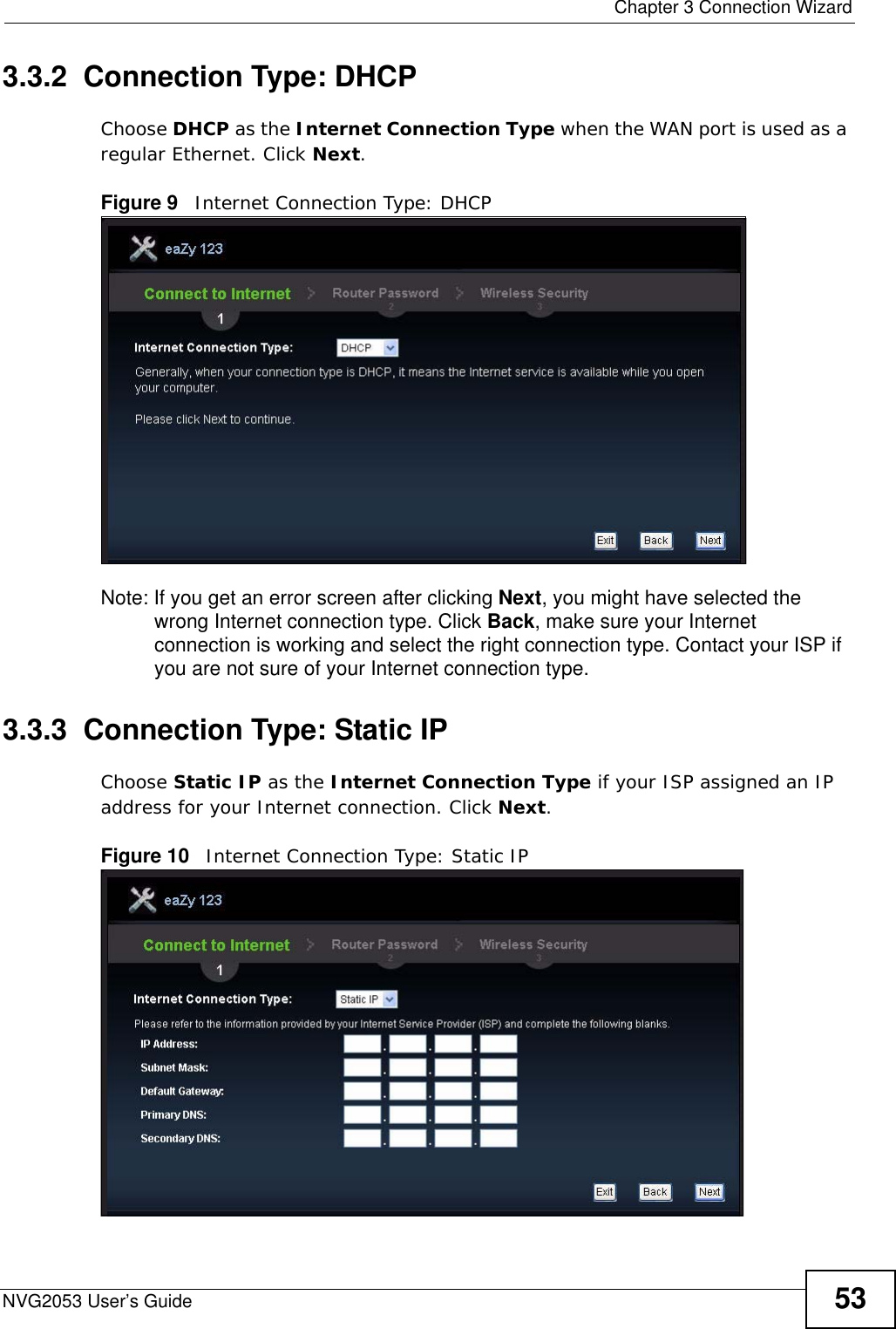
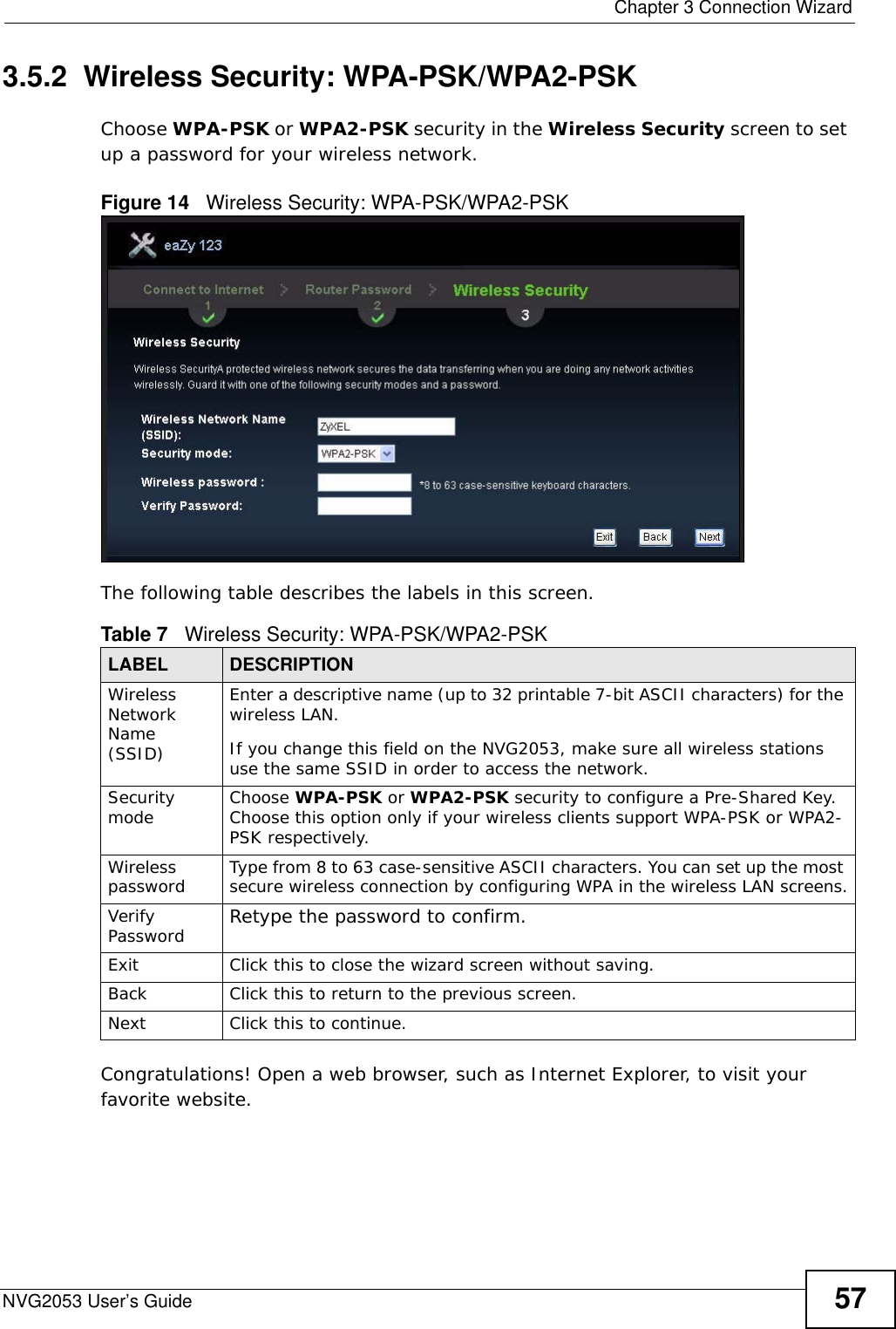
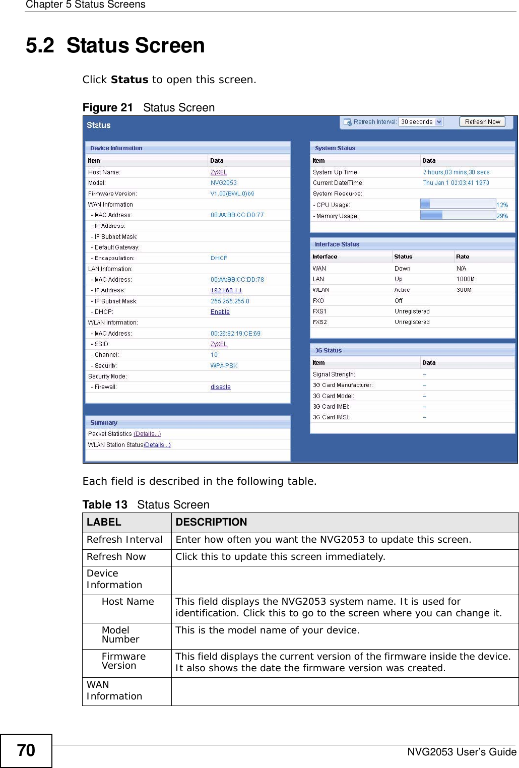
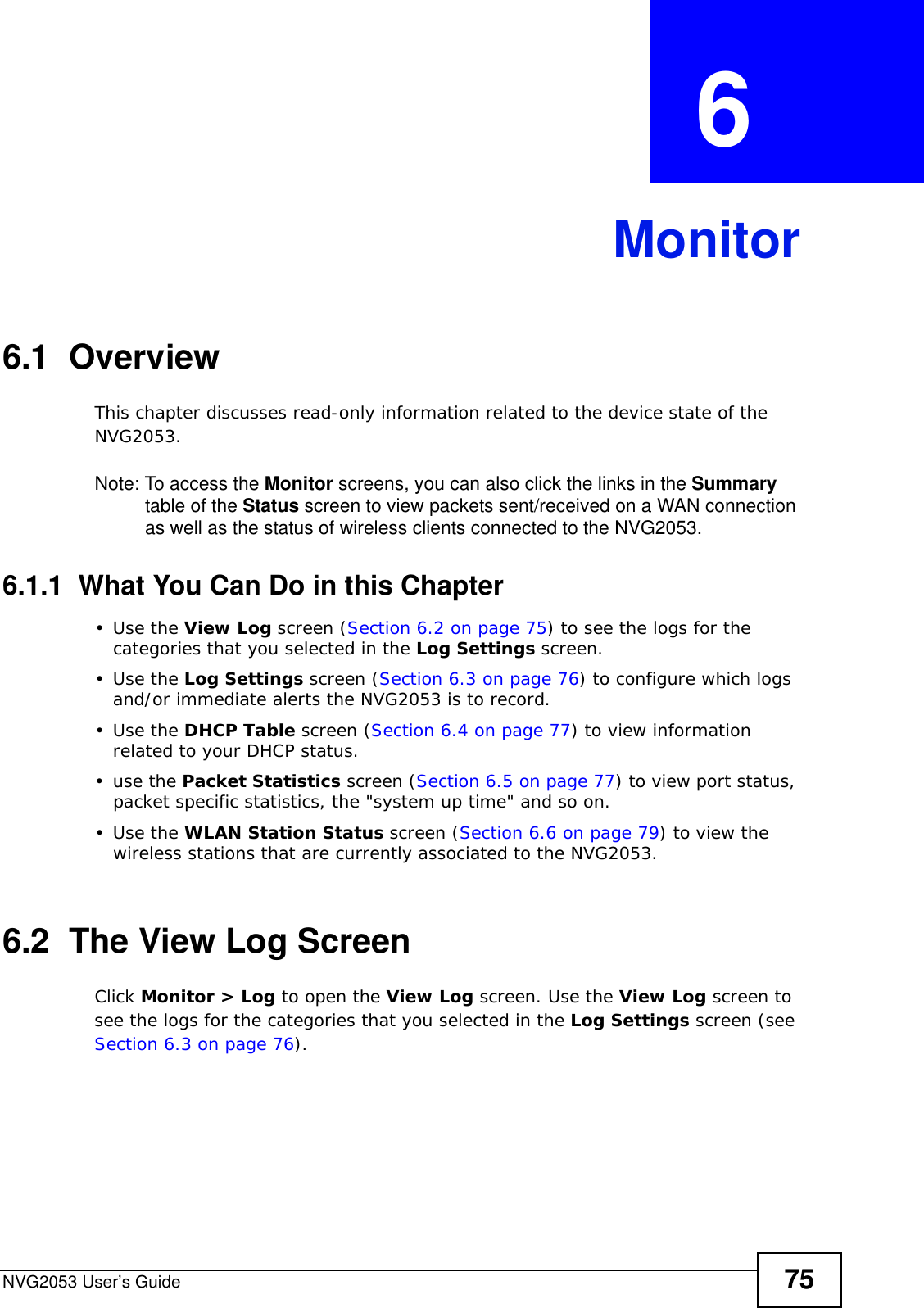
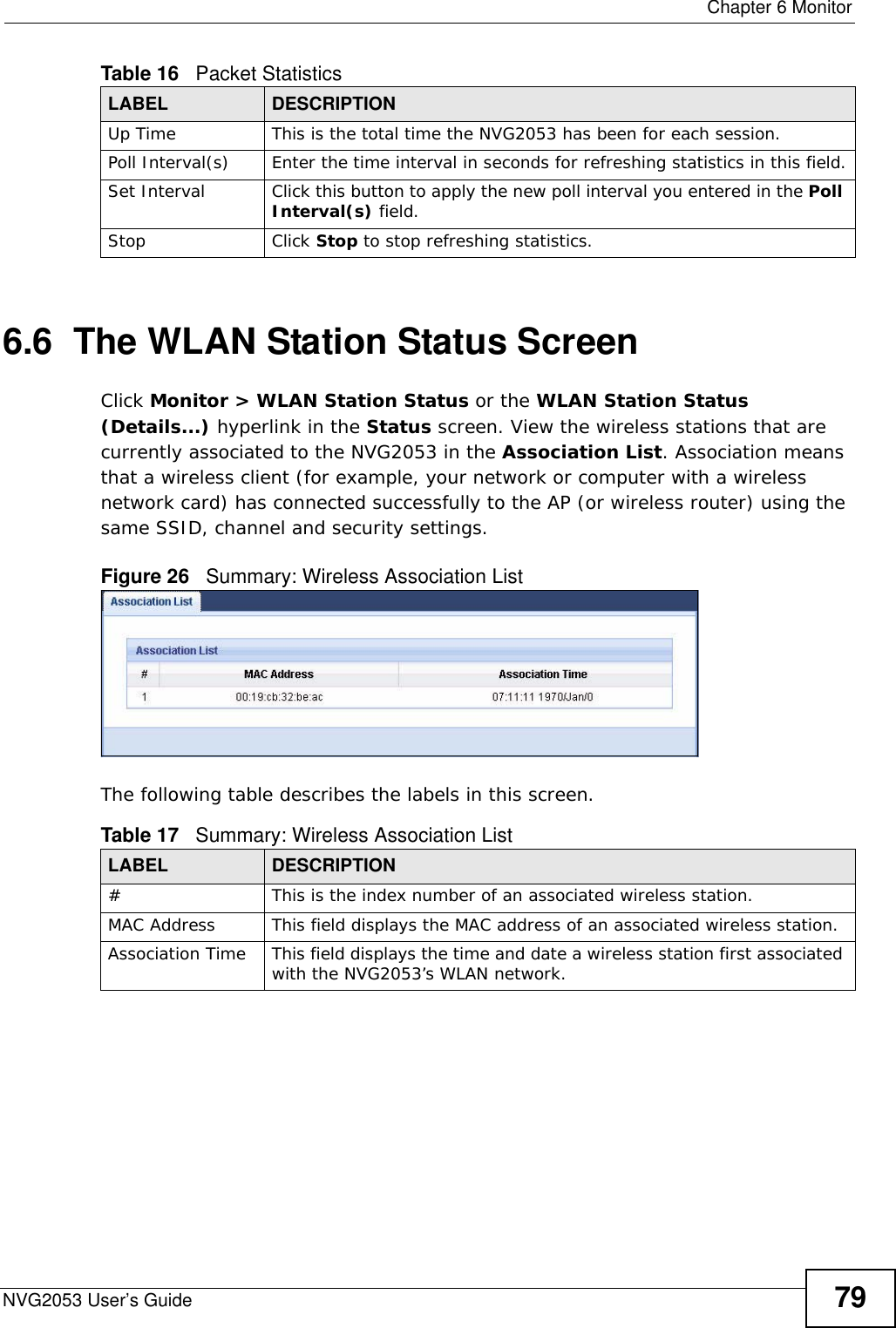
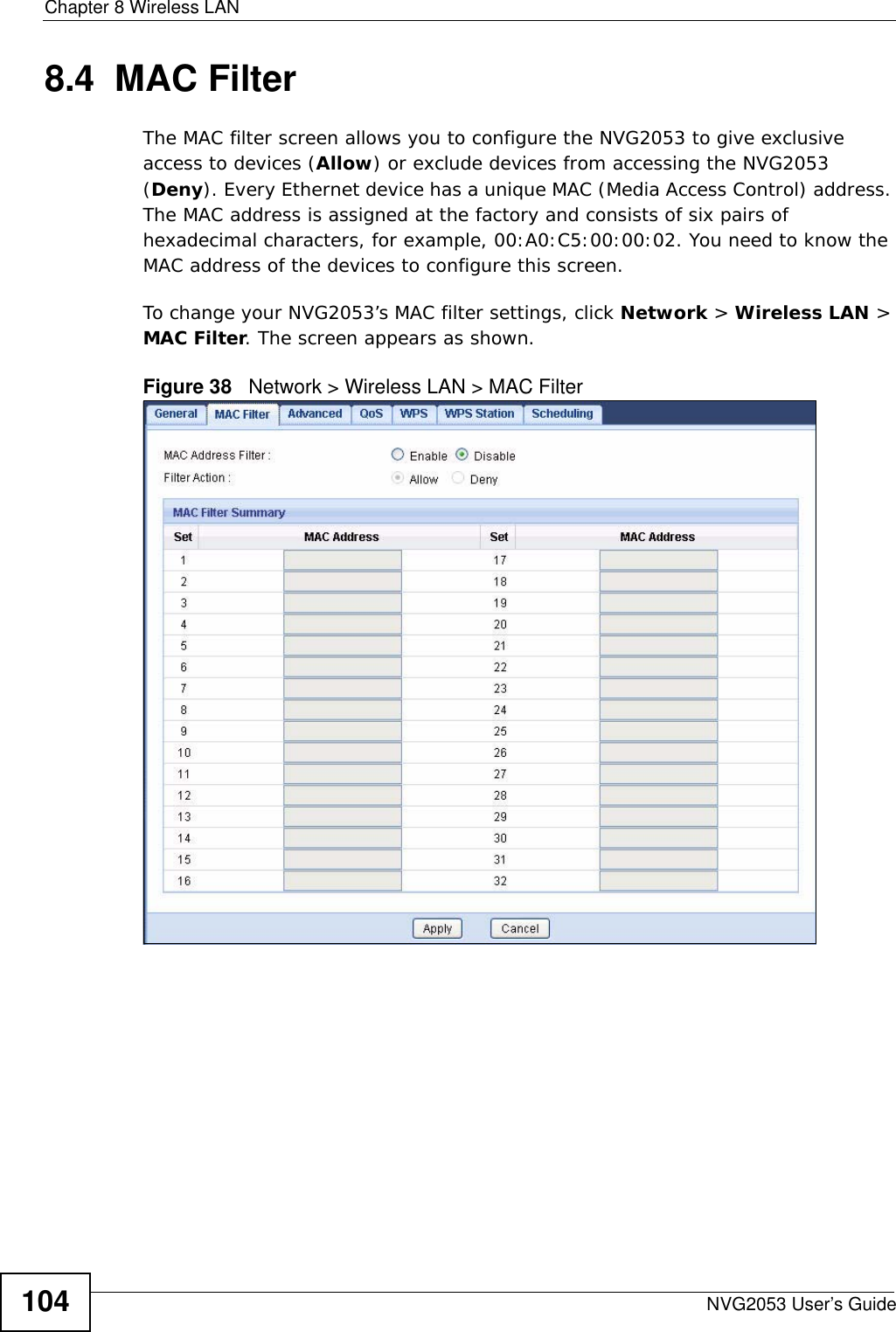
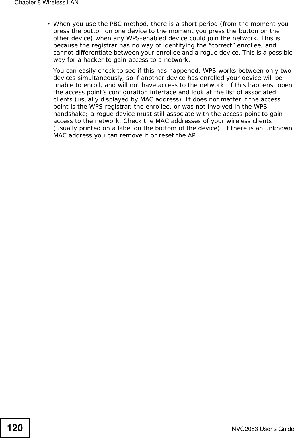
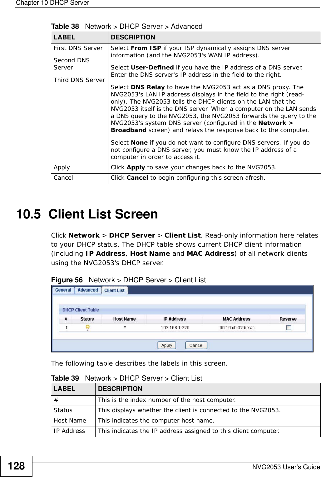
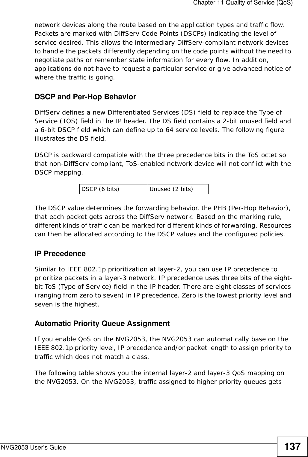
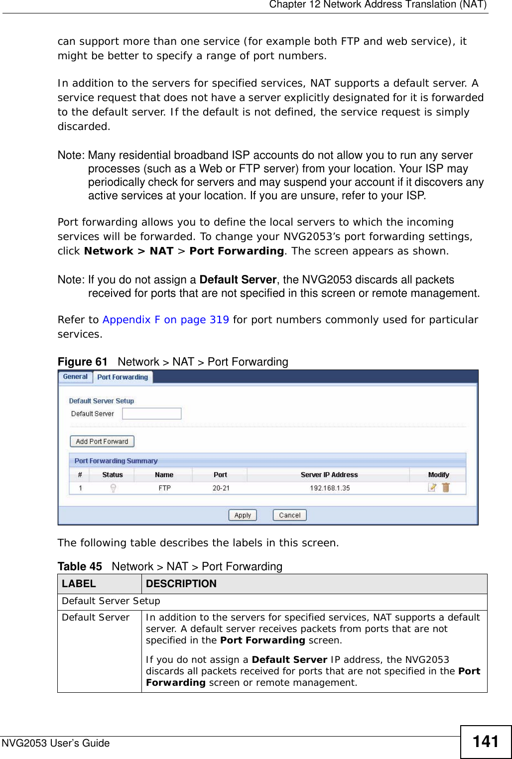
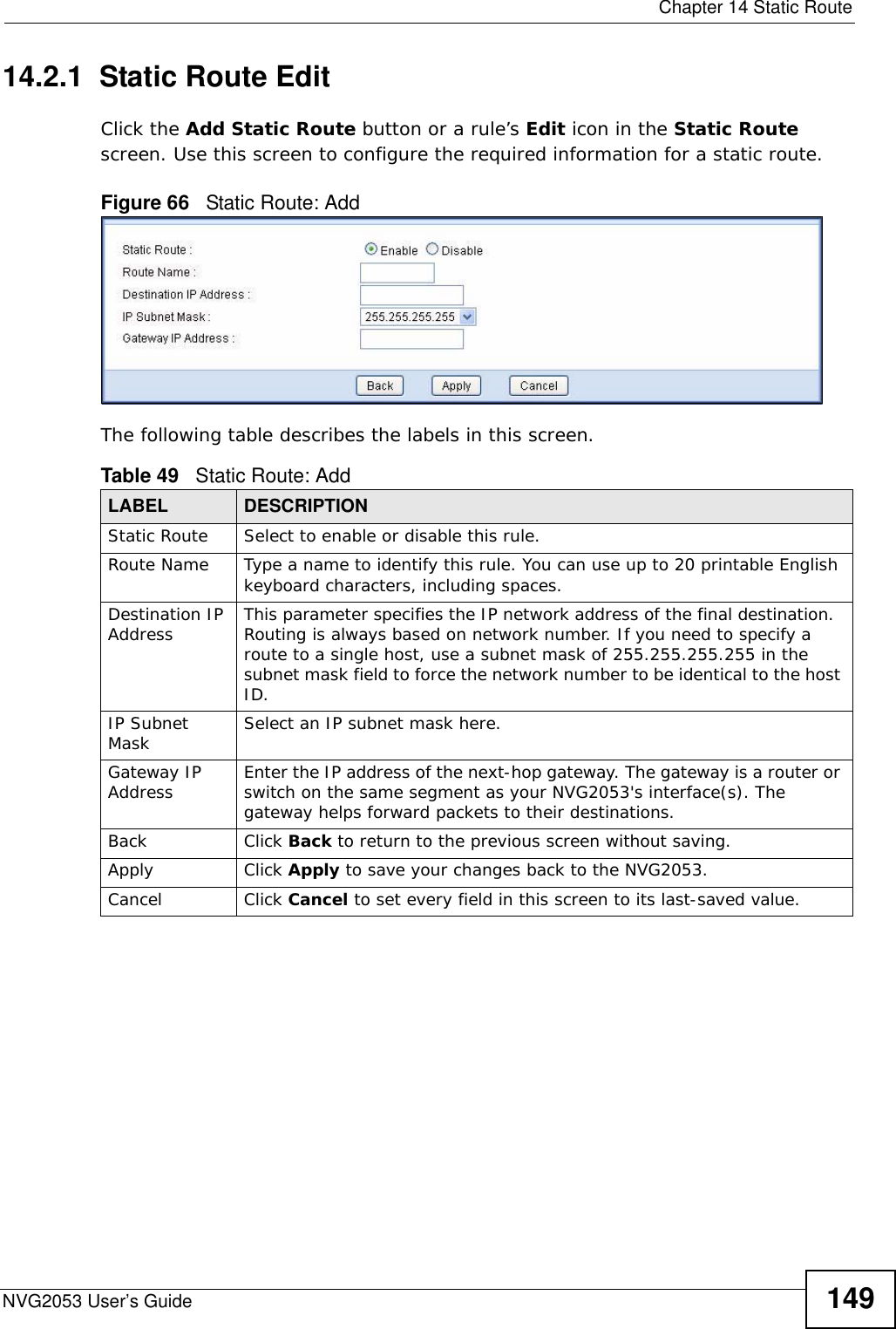
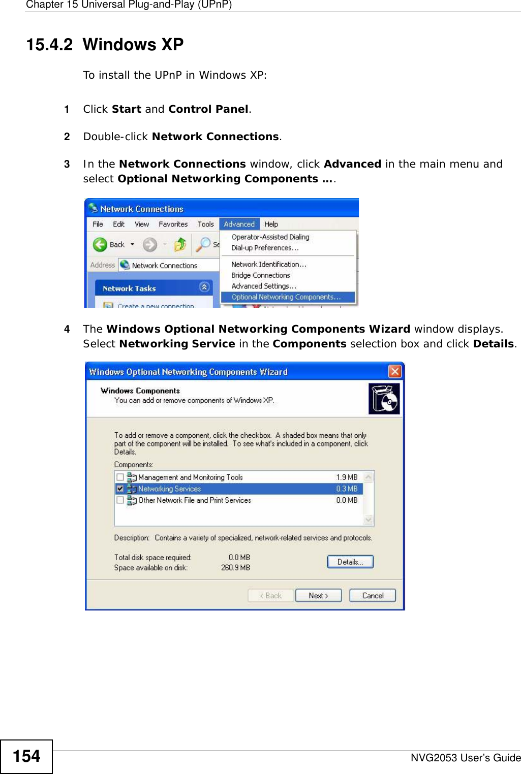
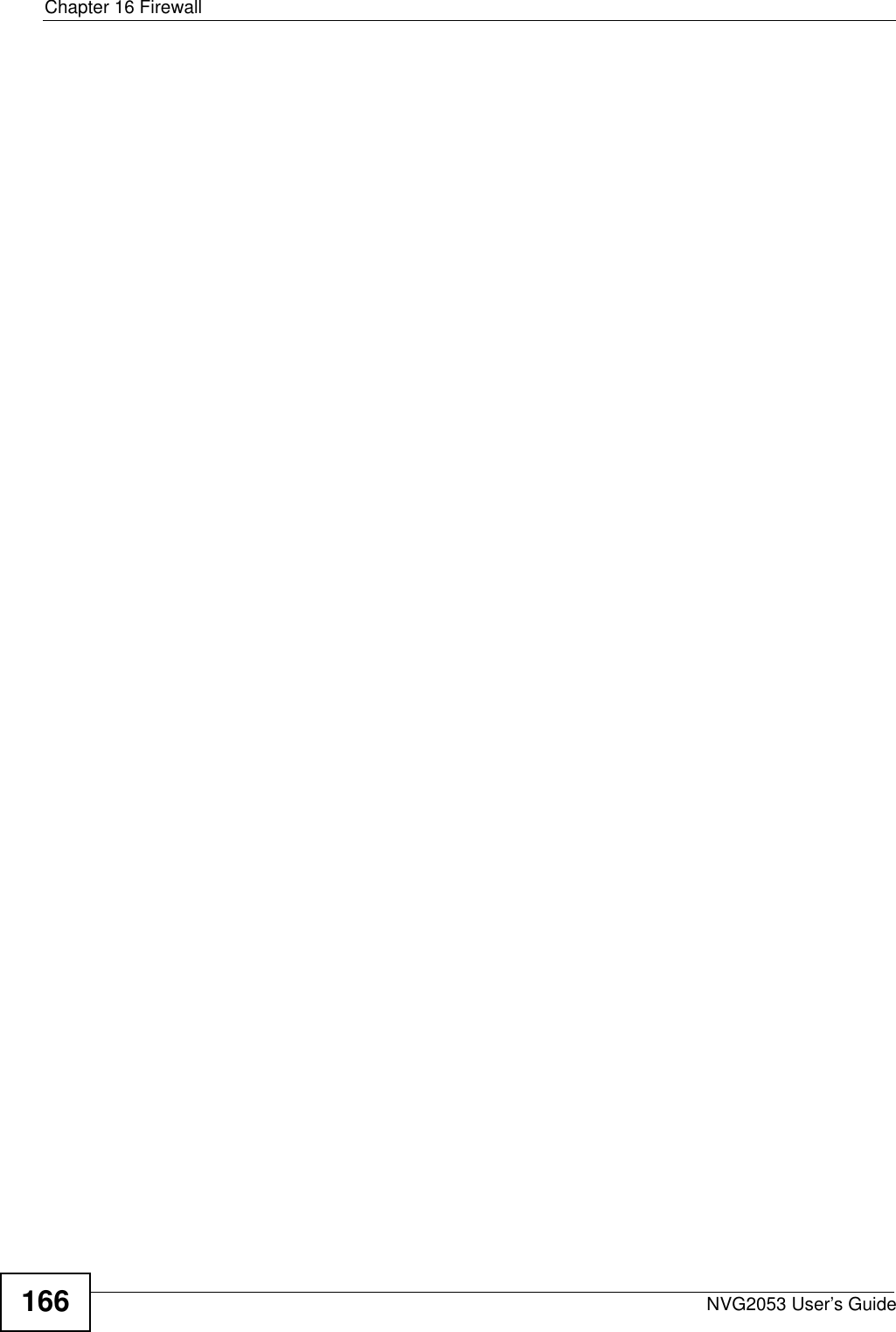
![Chapter 2 TutorialsNVG2053 User’s Guide40• IP Address: Enter the WAN IP address that your NVG2053 is currently using. You can find the IP address on the NVG2053’s Web Configurator Status page.Then you will need to configure the same account and host name on the NVG2053 later.2.5.2 Configuring DDNS on Your NVG20531Log into the NVG2053's advanced mode.2Configure the following settings in the Network > Dynamic DNS screen.2a Select Enable DDNS.2b Select WWW.DynDNS.ORG in the Service Provider field.2c Type “zyxelrouter.dyndns.org” in the Domain Name field.2d Enter the user name (“UserName1” for example) and password (“12345” for example).2e Select Use WAN IP Address for the IP address update policy.2f Click Apply.2.5.3 Testing the DDNS SettingNow you should be able to access the NVG2053 from the Internet. To test this:1Open a web browser on the computer (using the IP address a.b.c.d) that is connected to the Internet.2Type “http://zyxelrouter.dyndns.org” and press [Enter].](https://usermanual.wiki/ZyXEL-Communications/NVG2053.User-s-manual-1/User-Guide-1439016-Page-40.png)
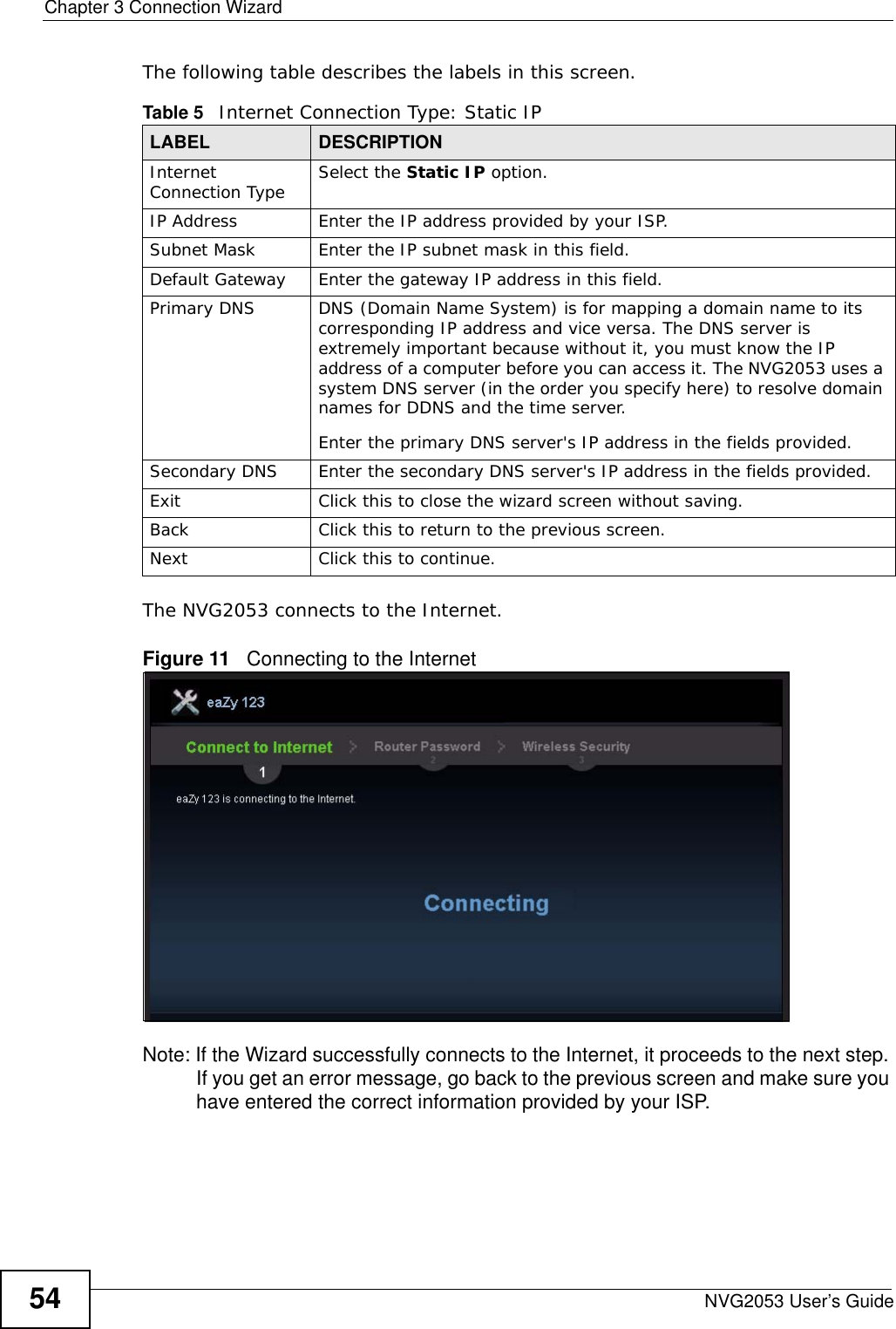
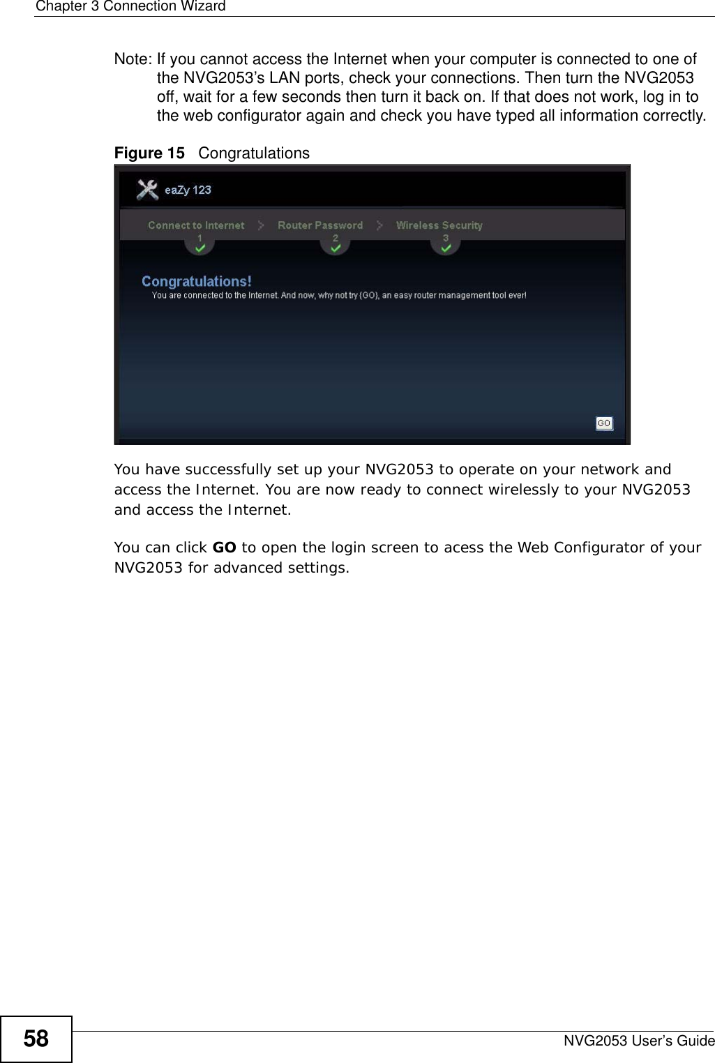

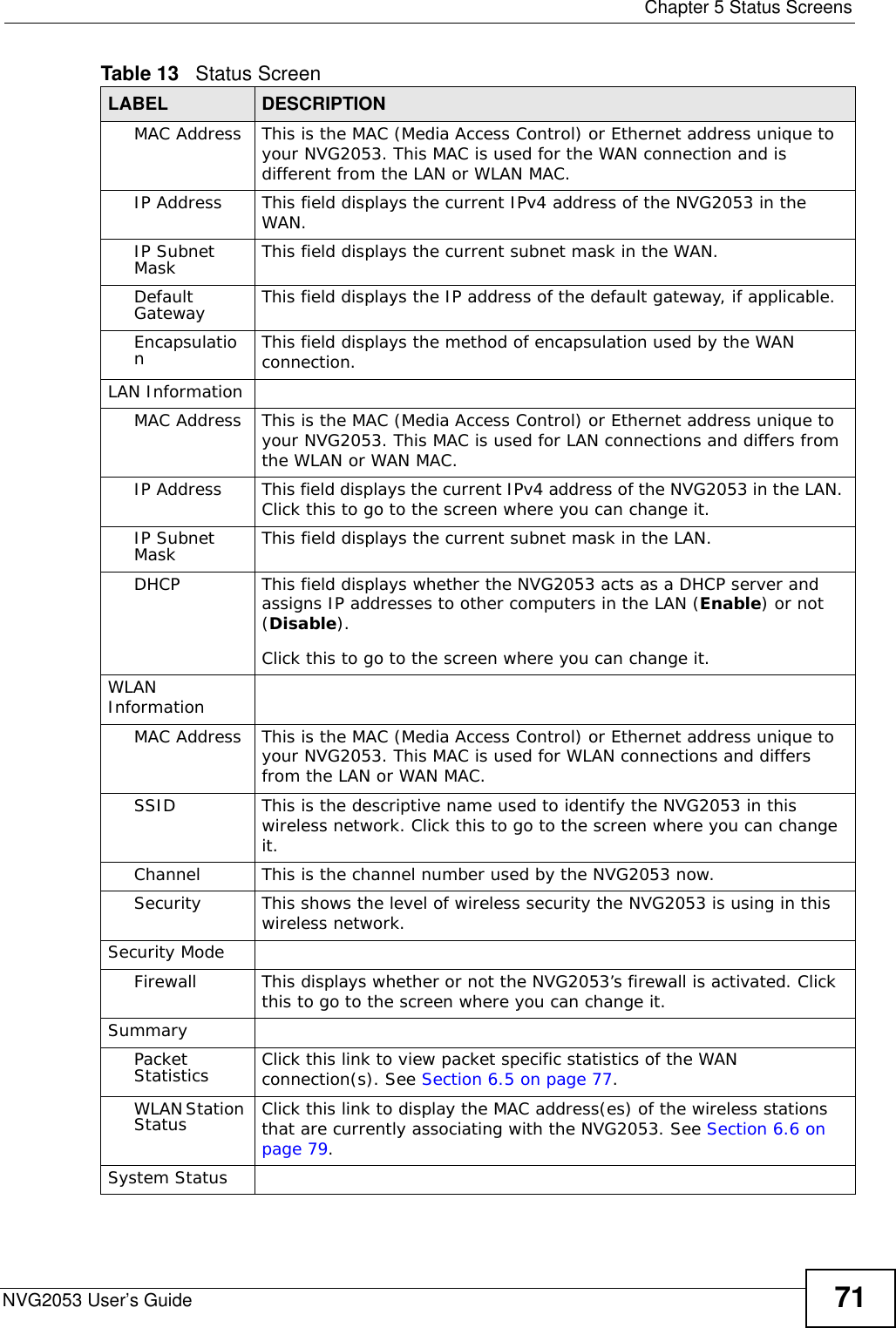

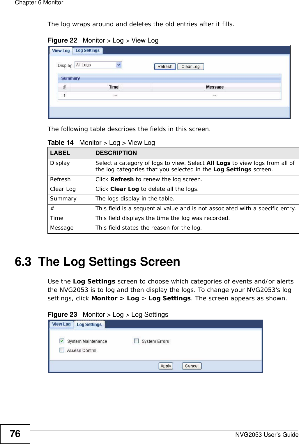

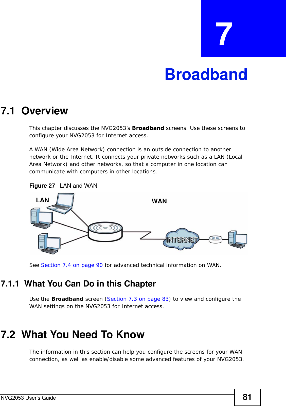
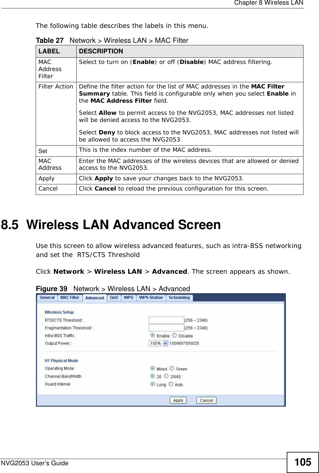
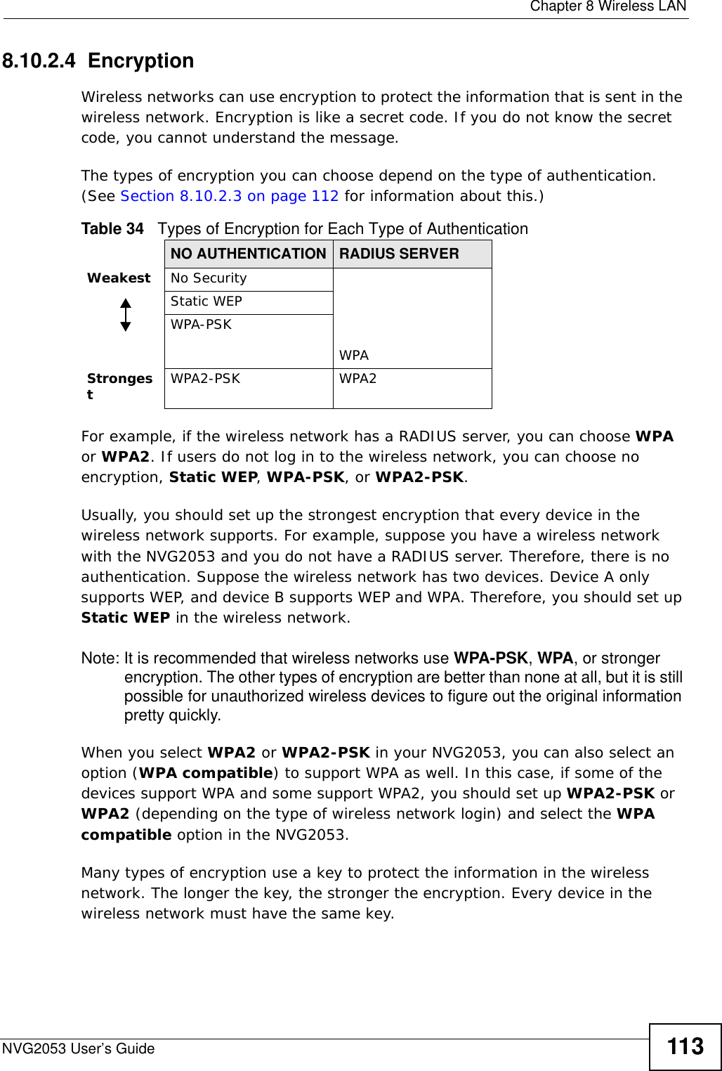
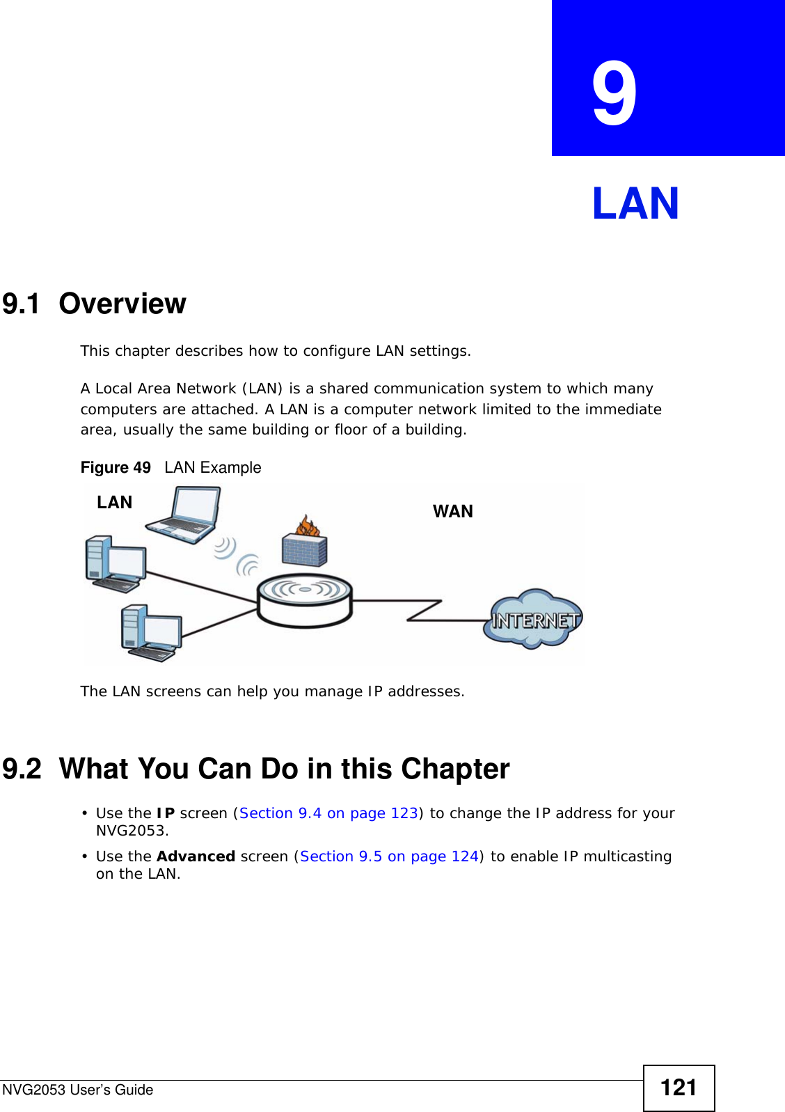
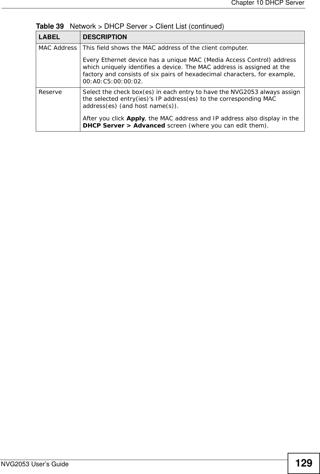

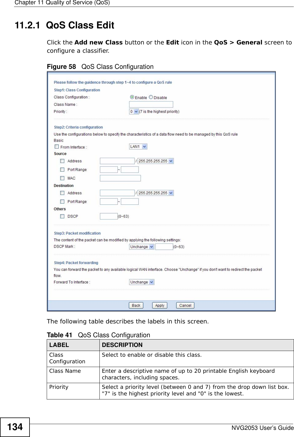
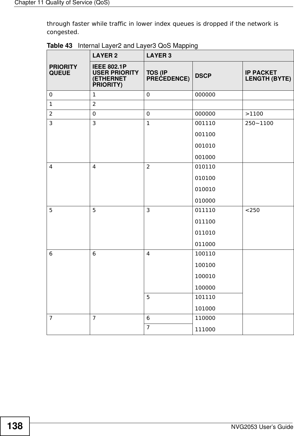
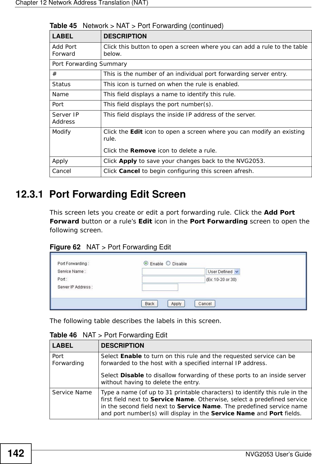

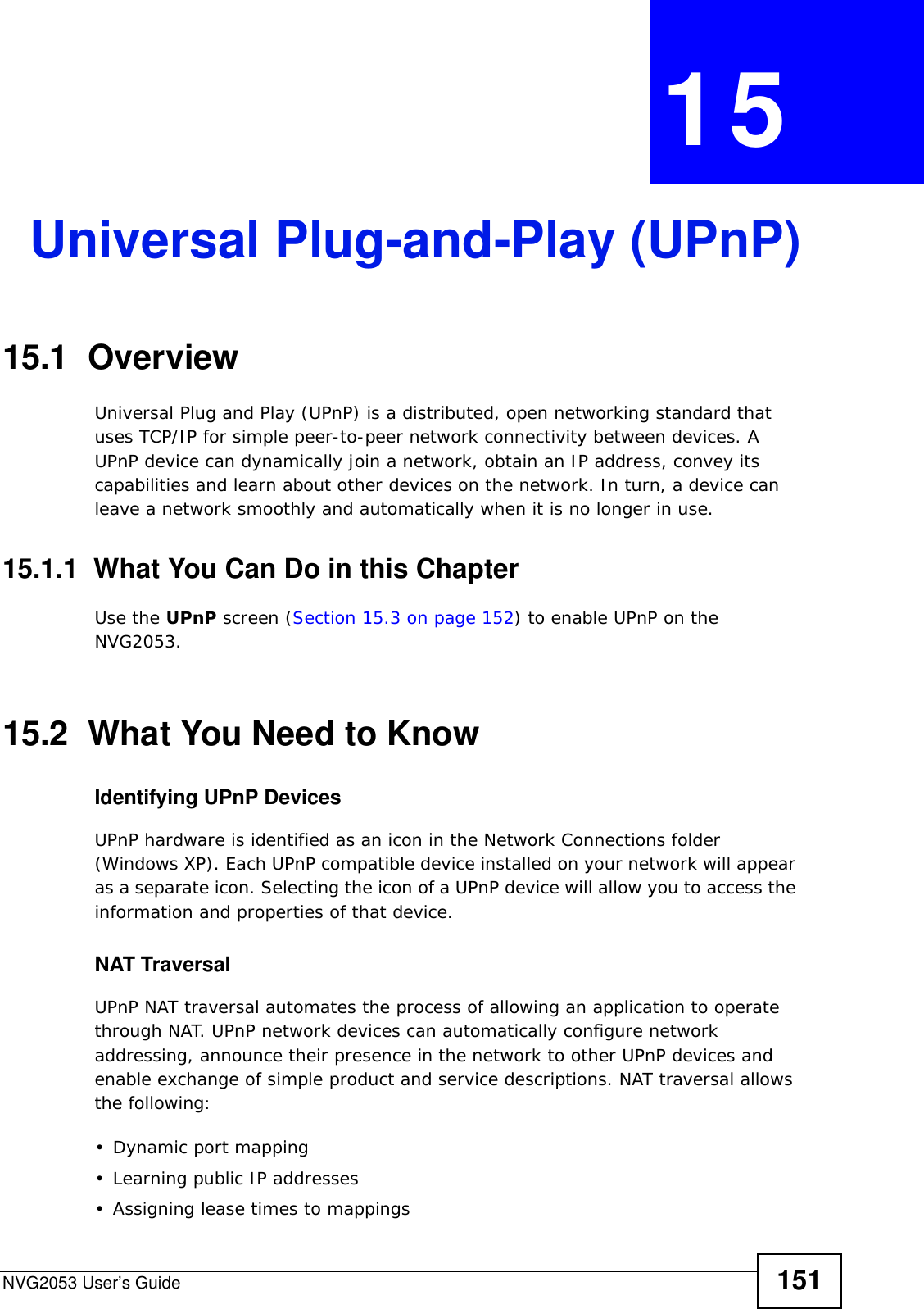
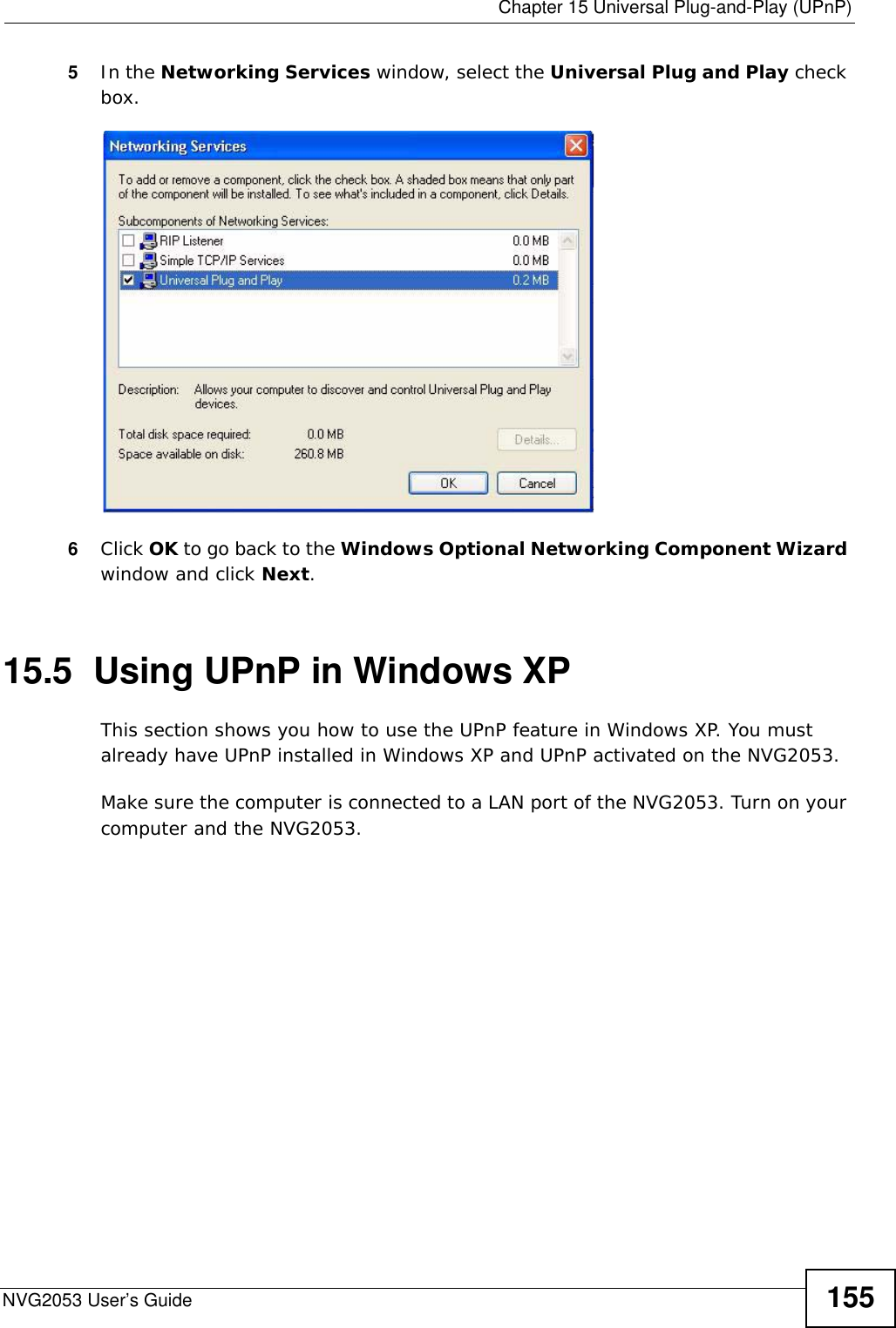
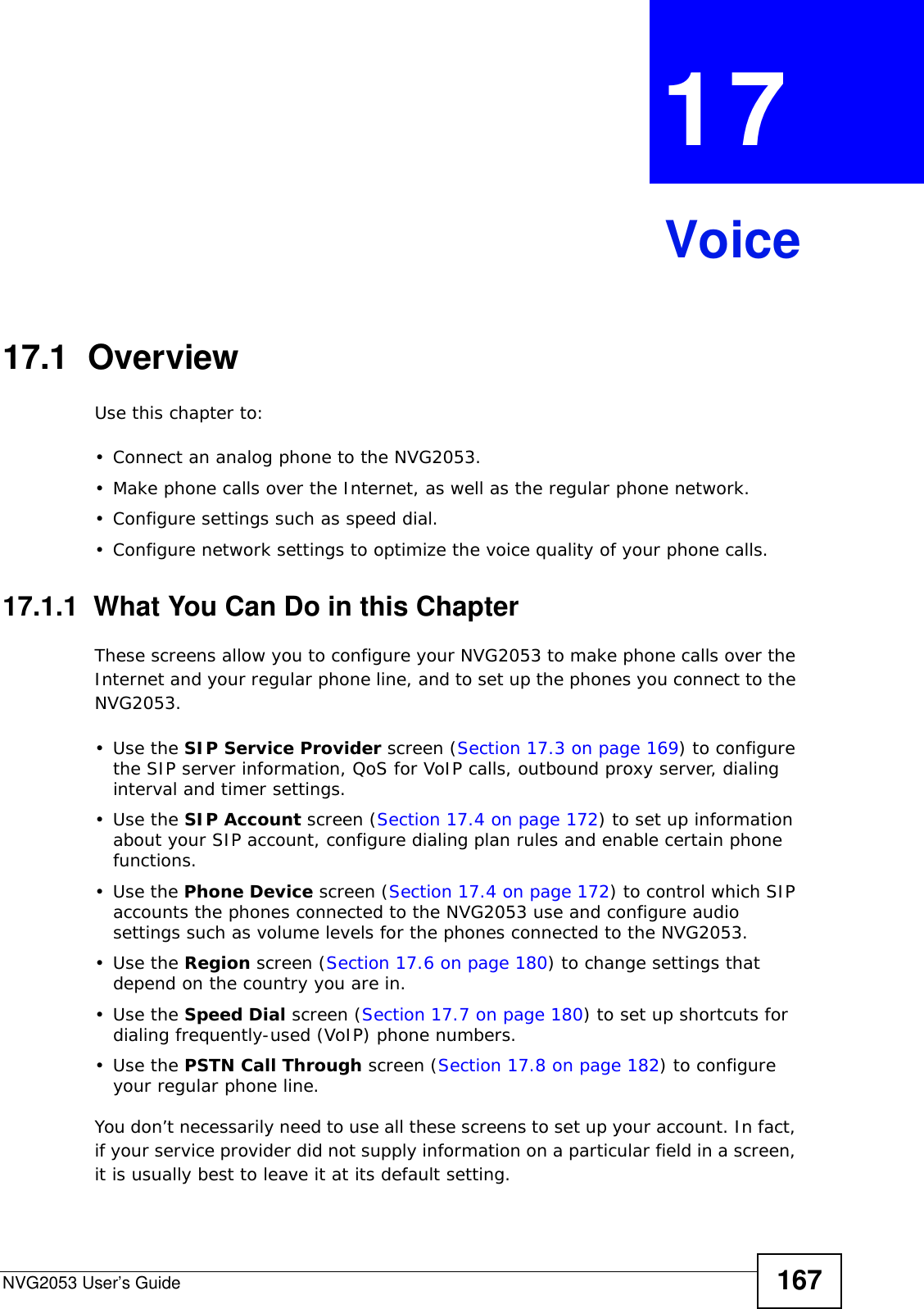
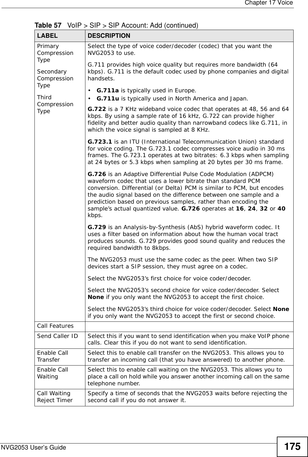
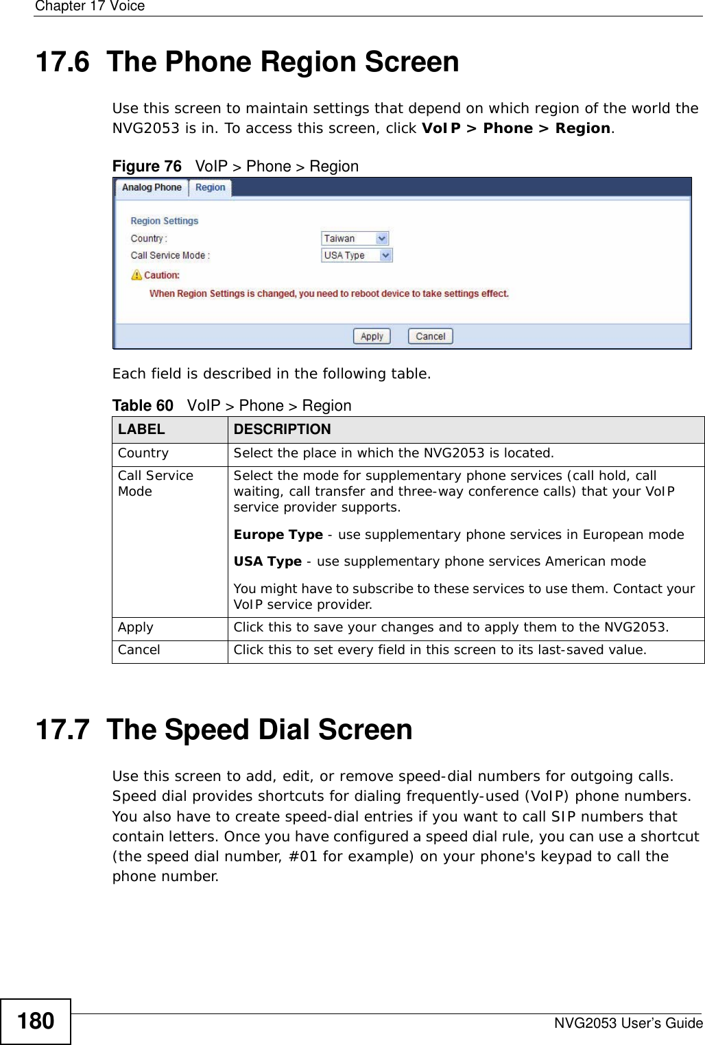
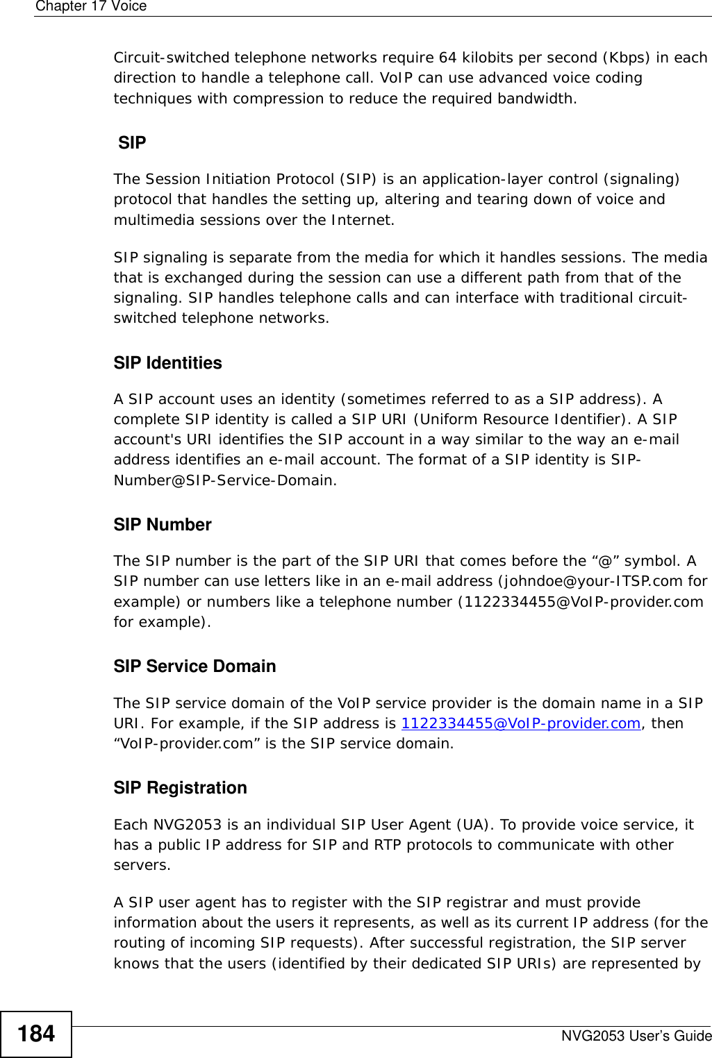
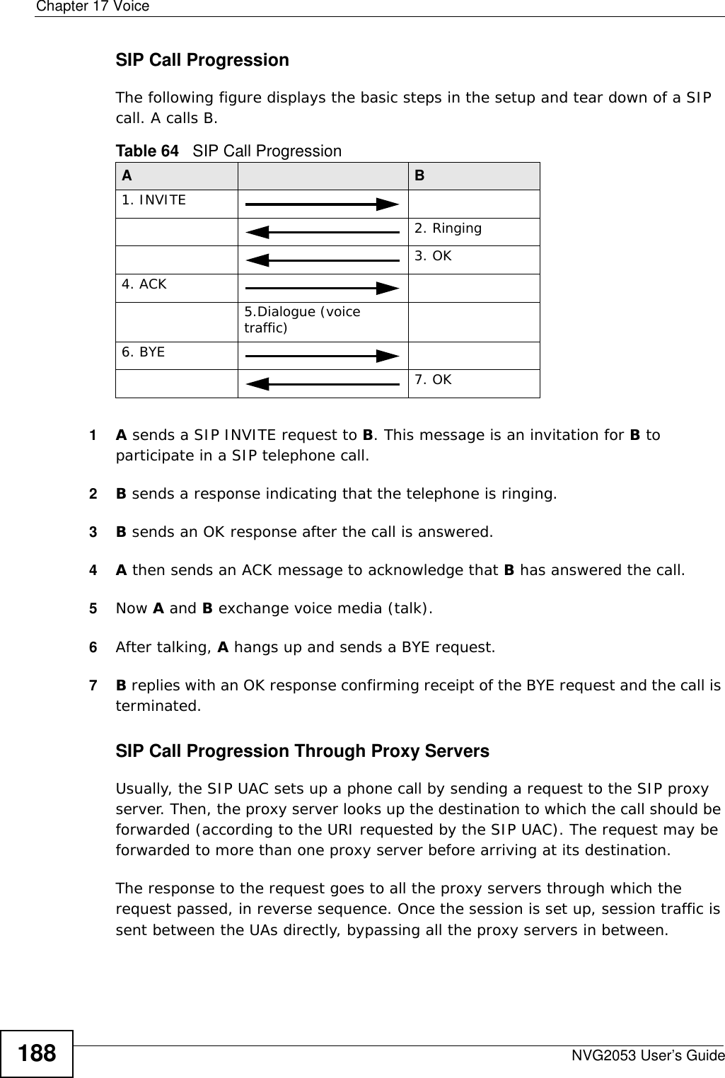
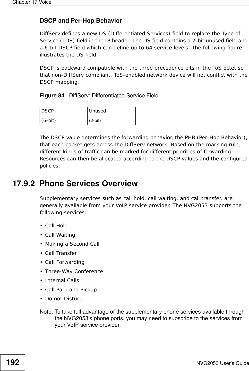
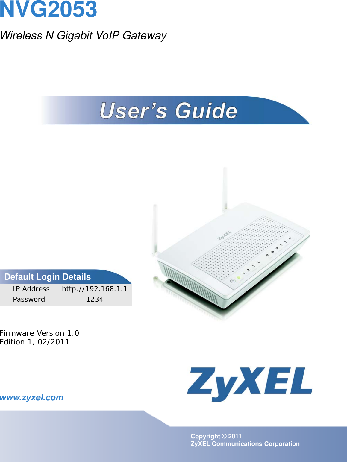
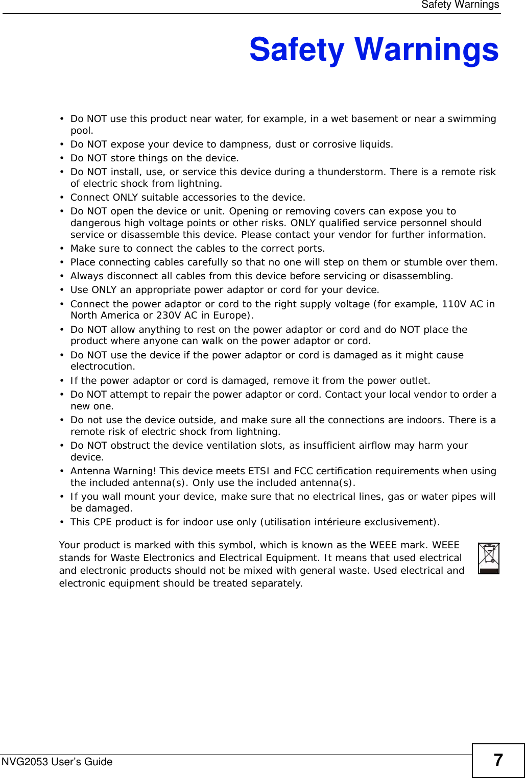
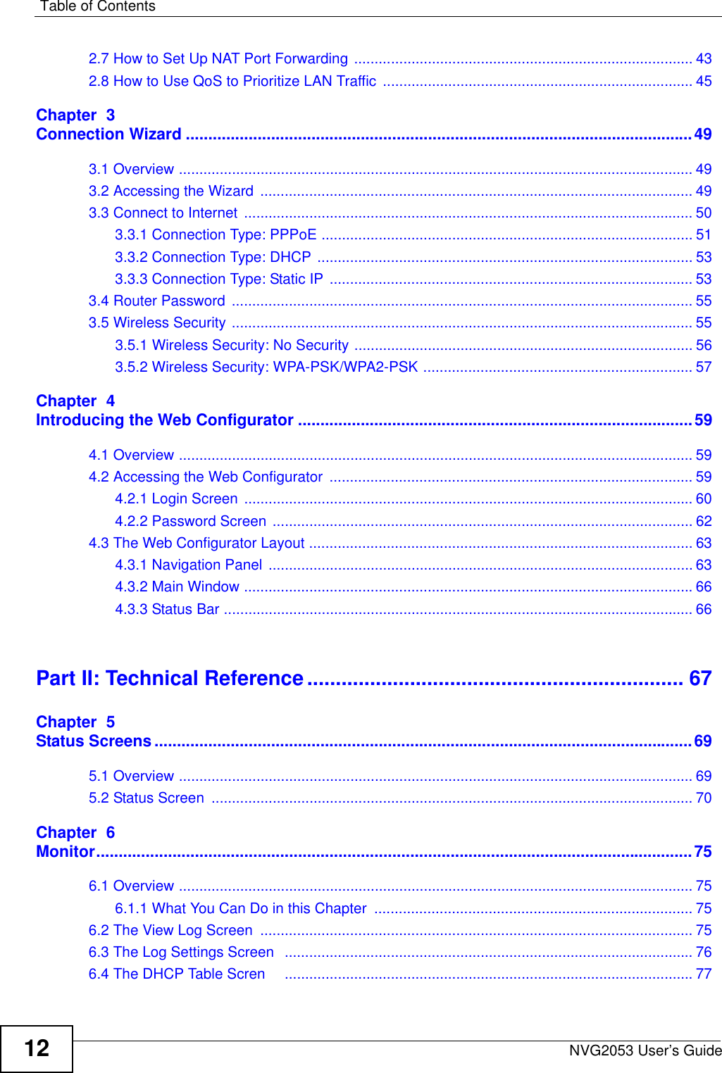
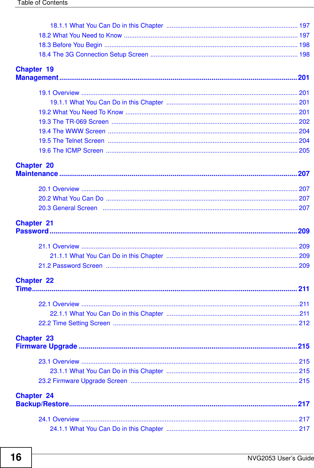
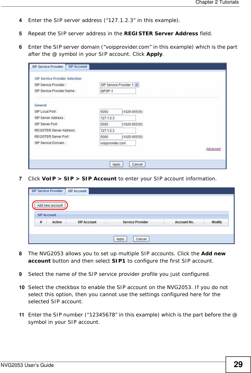
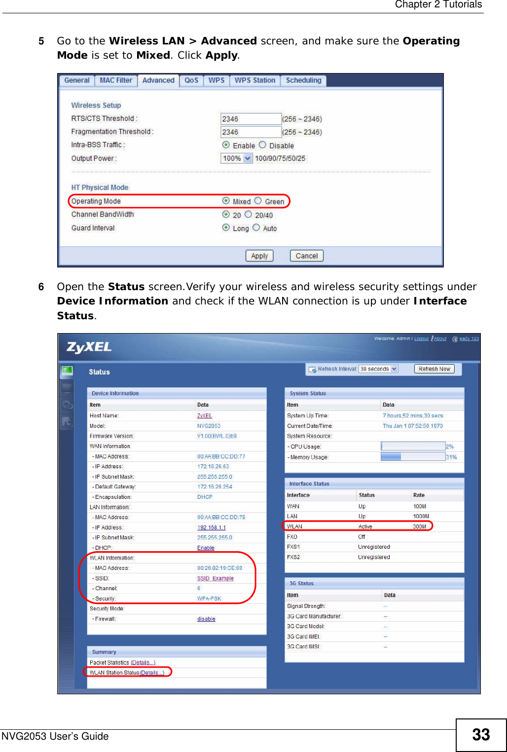
![Chapter 17 VoiceNVG2053 User’s Guide17617.4.2 Dial Plan RulesA dial plan defines the dialing patterns, such as the length and range of the digits for a telephone number. It also includes country codes, access codes, area codes, local numbers, long distance numbers or international call prefixes. For example, the dial plan ([2-9]xxxxxx) does not allow a local number which begins with 1 or 0.Without a dial plan, users have to manually enter the whole callee’s number and wait for the specified dialing interval to time out or press a terminator key (usually the pound key on the phone keypad) before the NVG2053 makes the call.The NVG2053 initializes a call when the dialed number matches any one of the rules in the dial plan. Dial plan rules follow these conventions:• The collection of rules is in parentheses ().Enable MWI Select this if you want to hear a waiting (beeping) dial tone on your phone when you have at least one voice message. Your VoIP service provider must support this feature.MWI Expired Enter the number of seconds the SIP server should provide the message waiting service each time the NVG2053 subscribes to the service. Before this time passes, the NVG2053 automatically subscribes again.Enable Unconditional ForwardSelect this if you want the NVG2053 to forward all incoming calls to the specified phone number. Specify the phone number in the To Number field on the right.Enable Busy Forward Select this if you want the NVG2053 to forward incoming calls to the specified phone number if the phone port is busy. Specify the phone number in the To Number field on the right.If you have call waiting, the incoming call is forwarded to the specified phone number if you reject or ignore the second incoming call.Enable No Answer Forward Select this if you want the NVG2053 to forward incoming calls to the specified phone number if the call is unanswered. (See No Answer Ring Count.) Specify the phone number in the To Number field on the right.No Answer Ring Count This field is used by the Active No Answer Forward feature.Enter the number of telephone rings the NVG2053 should wait for you to answer an incoming call before it considers the call is unanswered.Enable Do Not Disturb Select this to set your phone to not ring when someone calls you.Back Click Back to return to the previous screen without saving.Apply Click Apply to save your changes back to the NVG2053.Cancel Click Cancel to set every field in this screen to its last-saved value.Table 57 VoIP > SIP > SIP Account: Add (continued)LABEL DESCRIPTION](https://usermanual.wiki/ZyXEL-Communications/NVG2053.User-s-manual-1/User-Guide-1439016-Page-176.png)
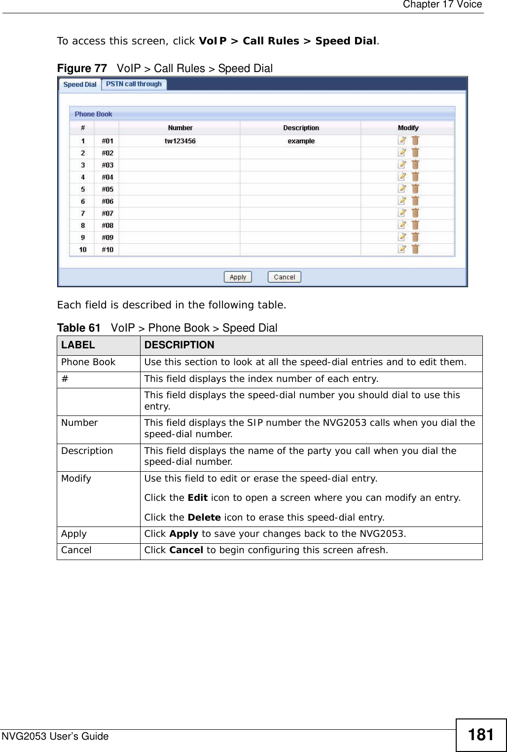
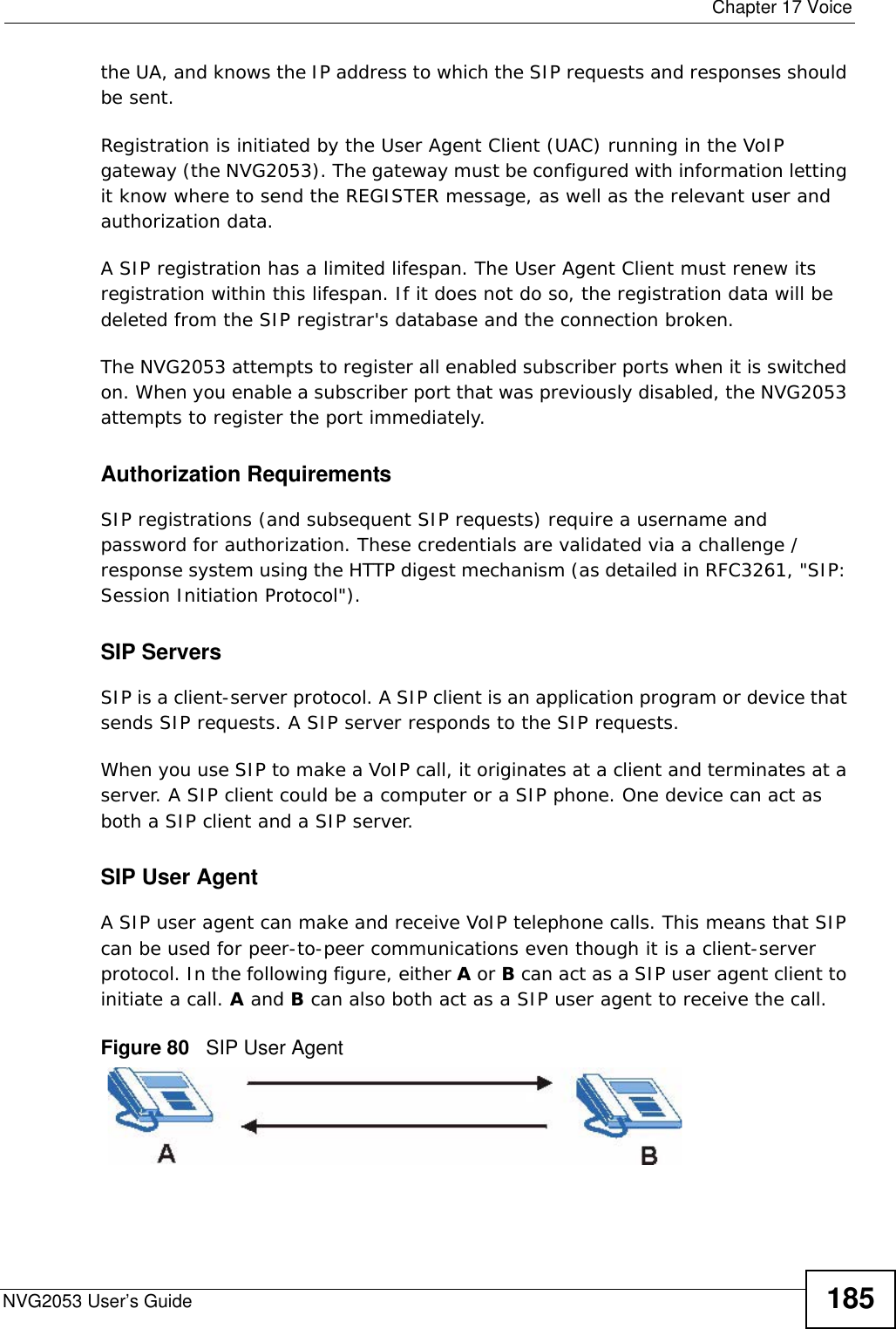
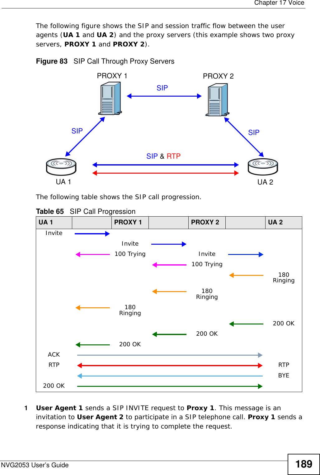
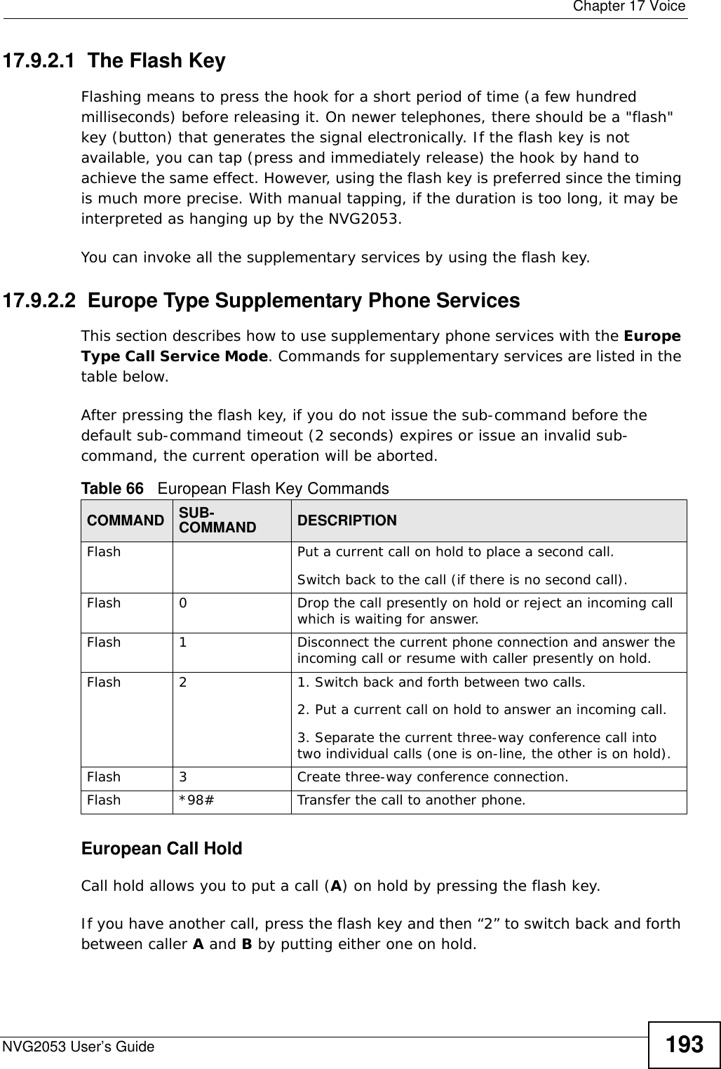
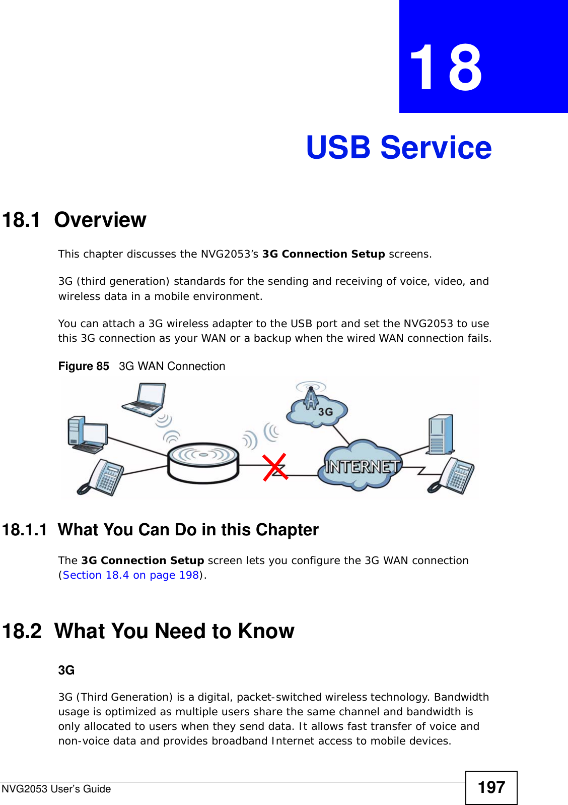
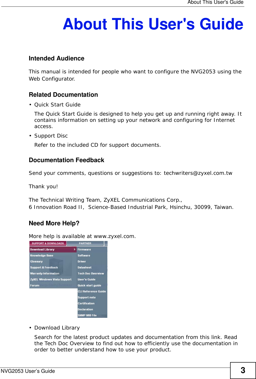
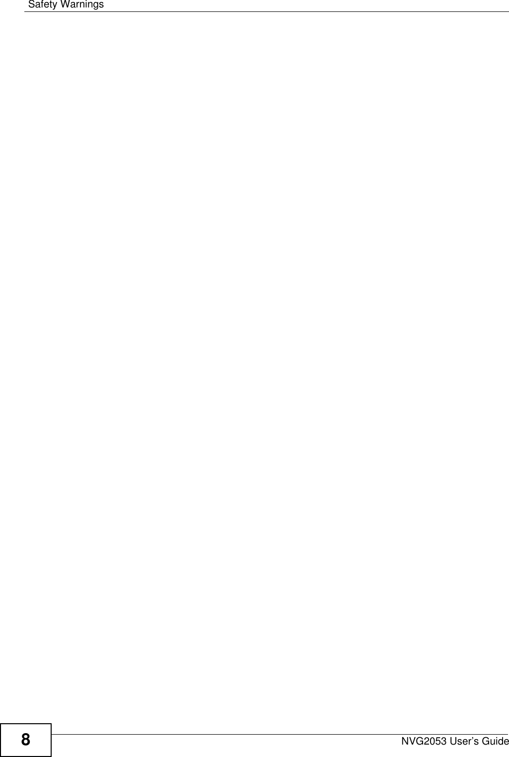
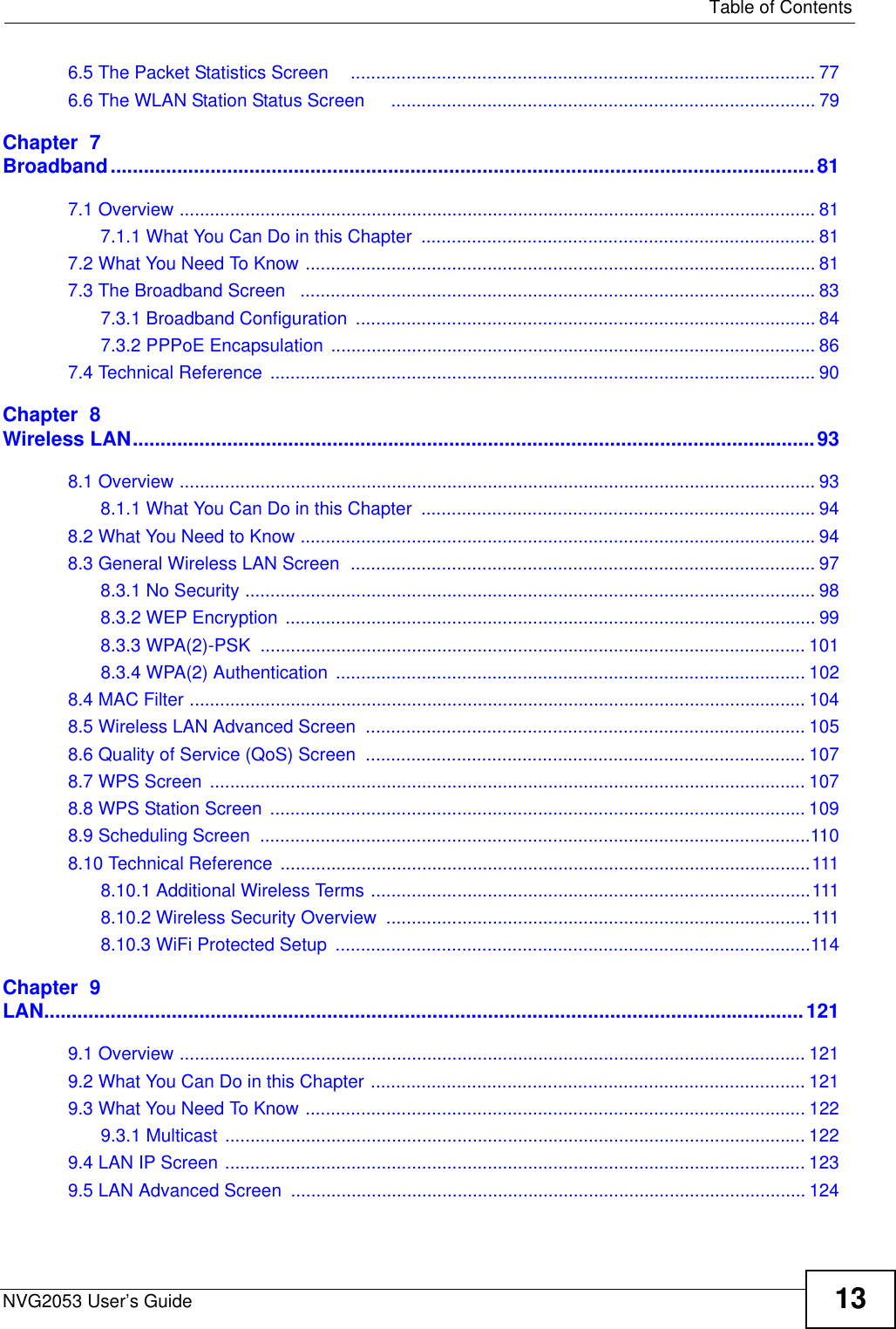
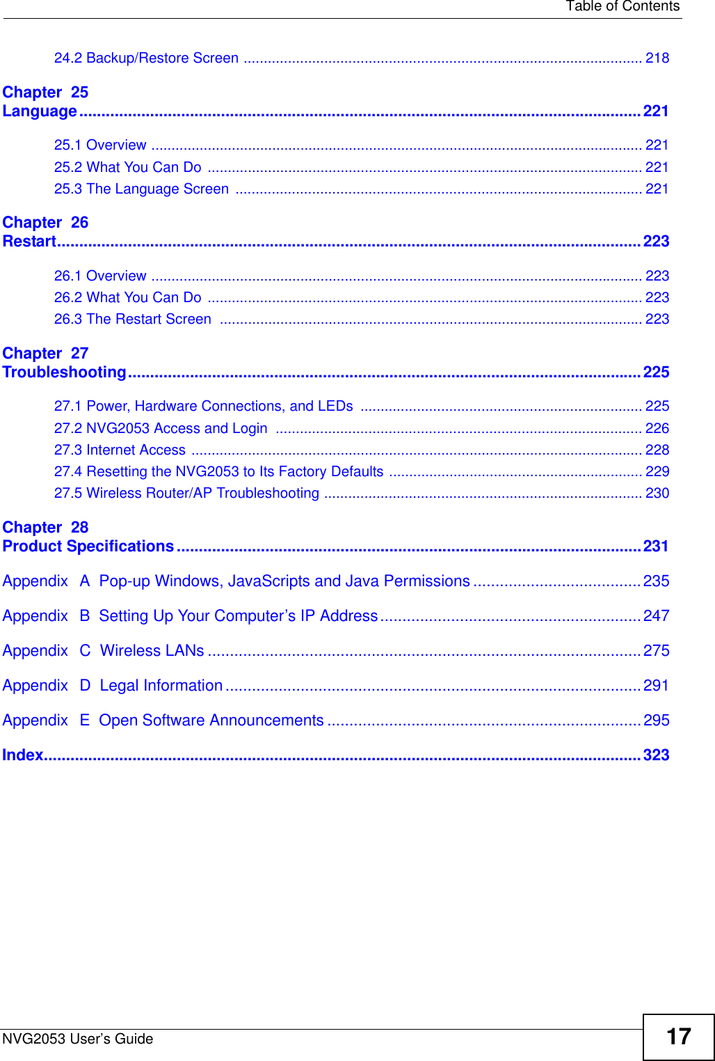
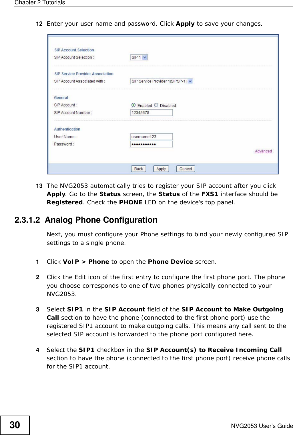
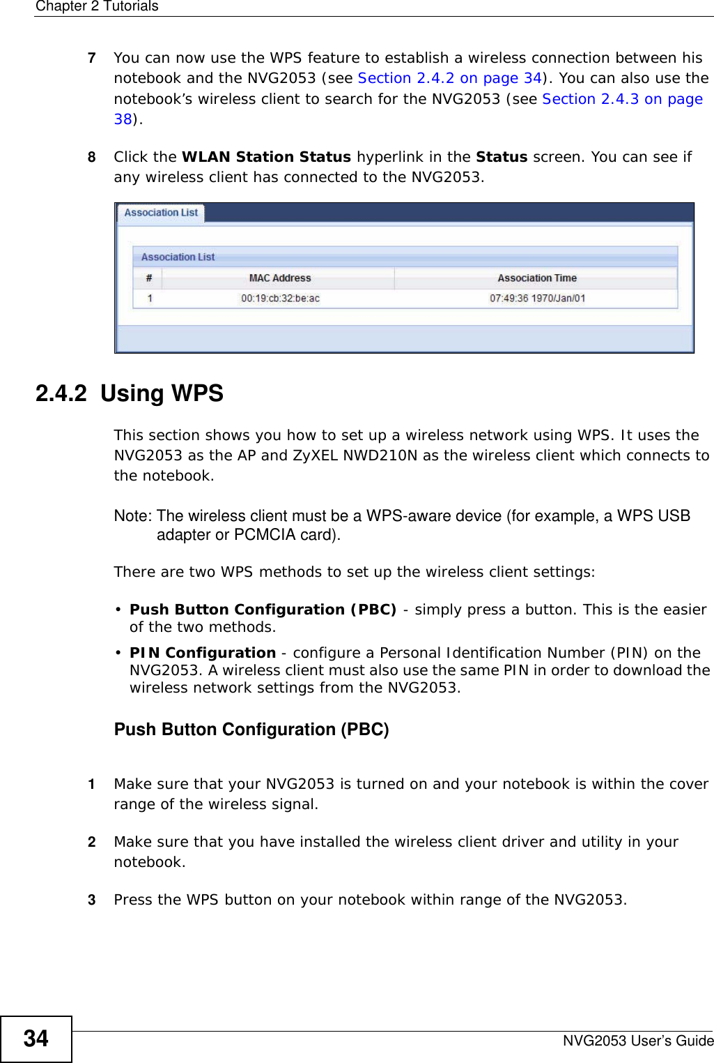
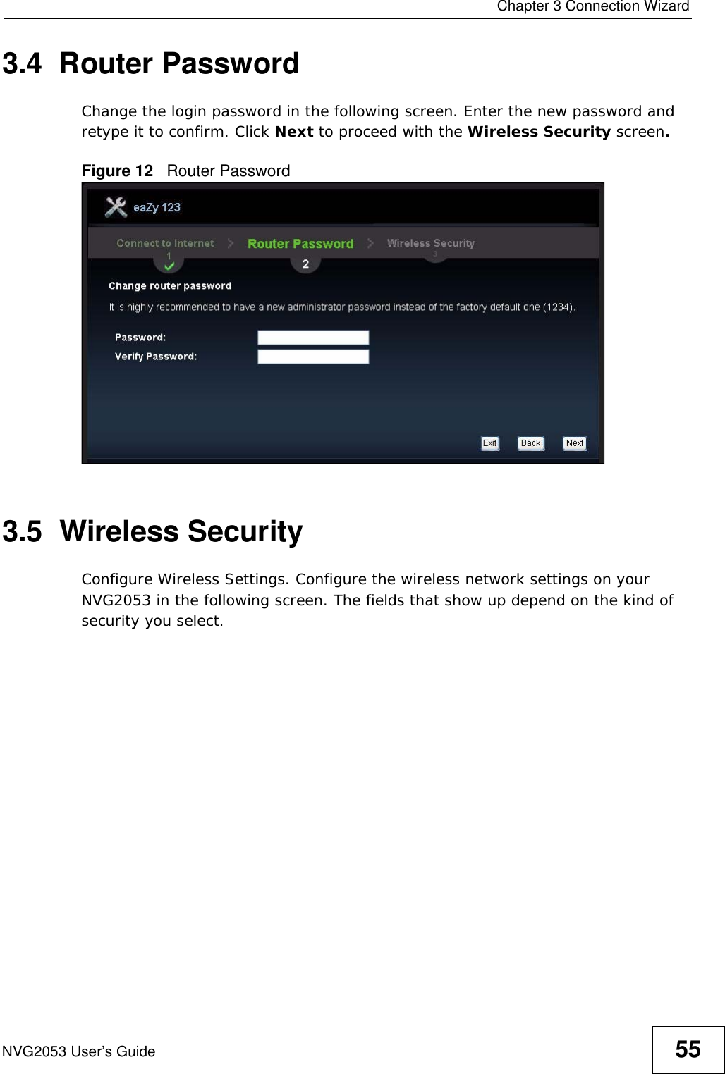
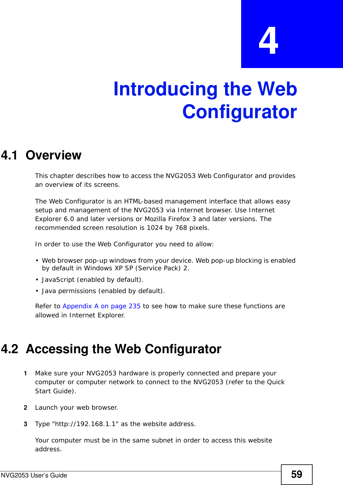
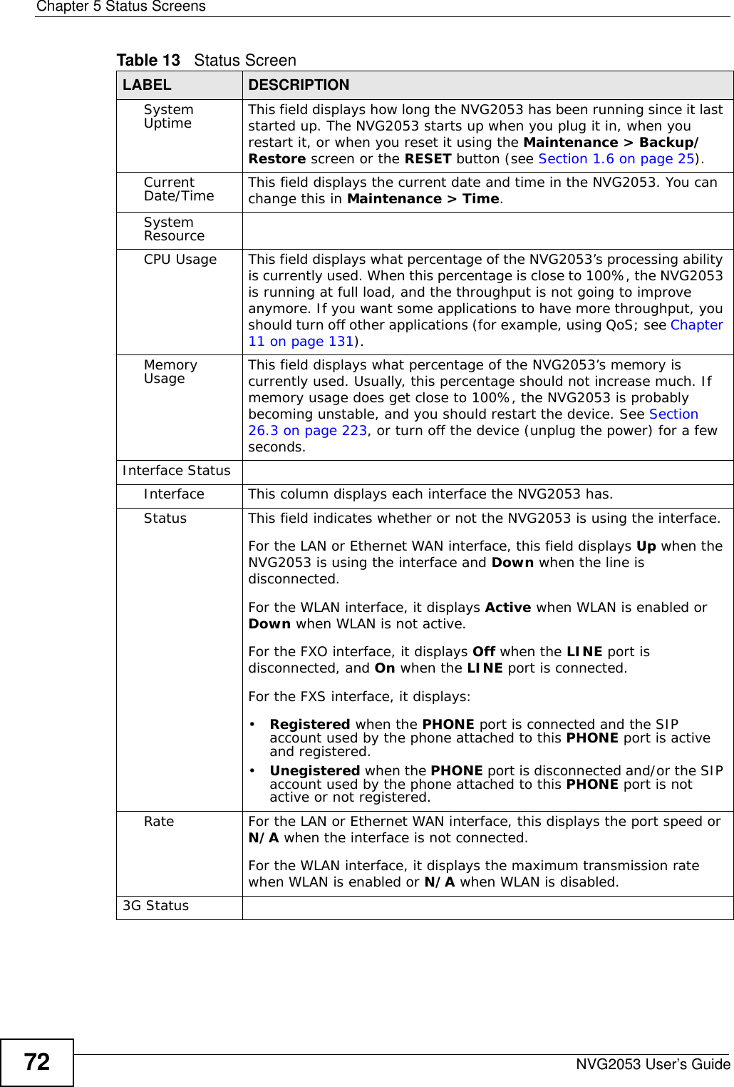
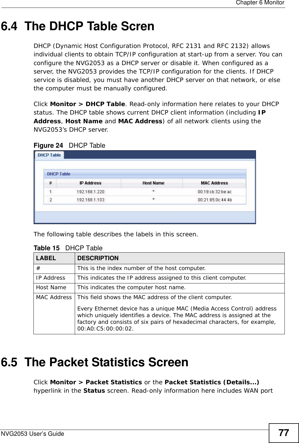
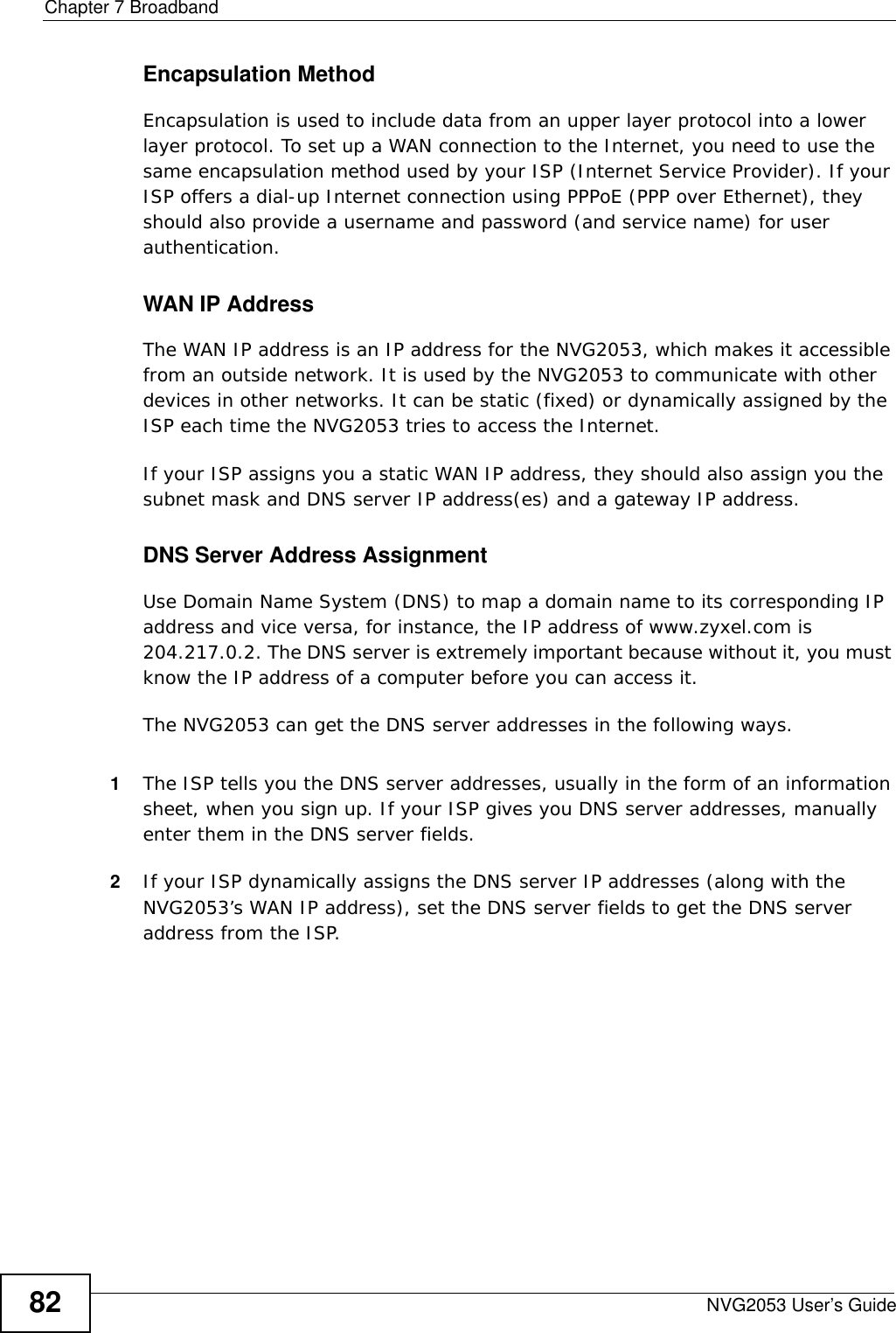
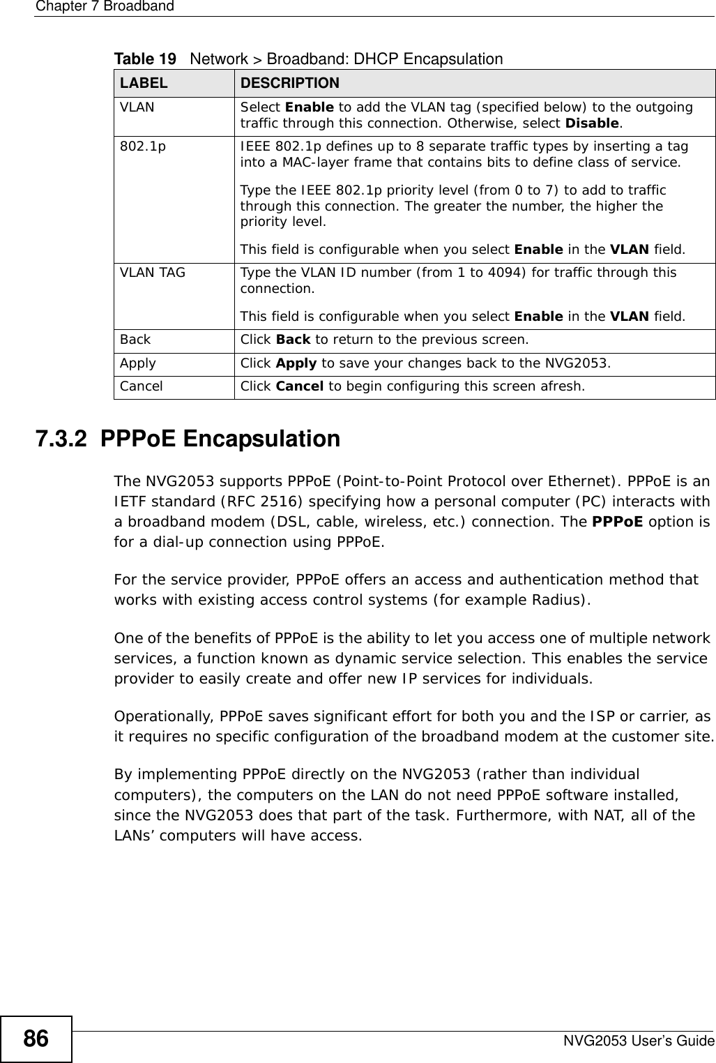
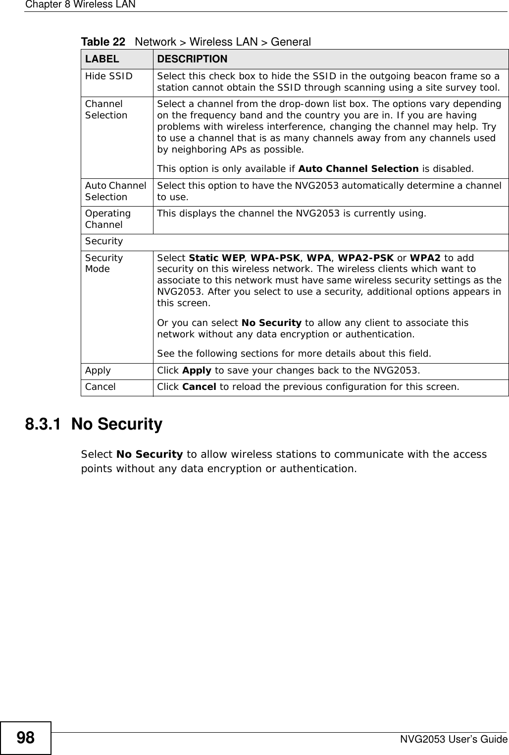
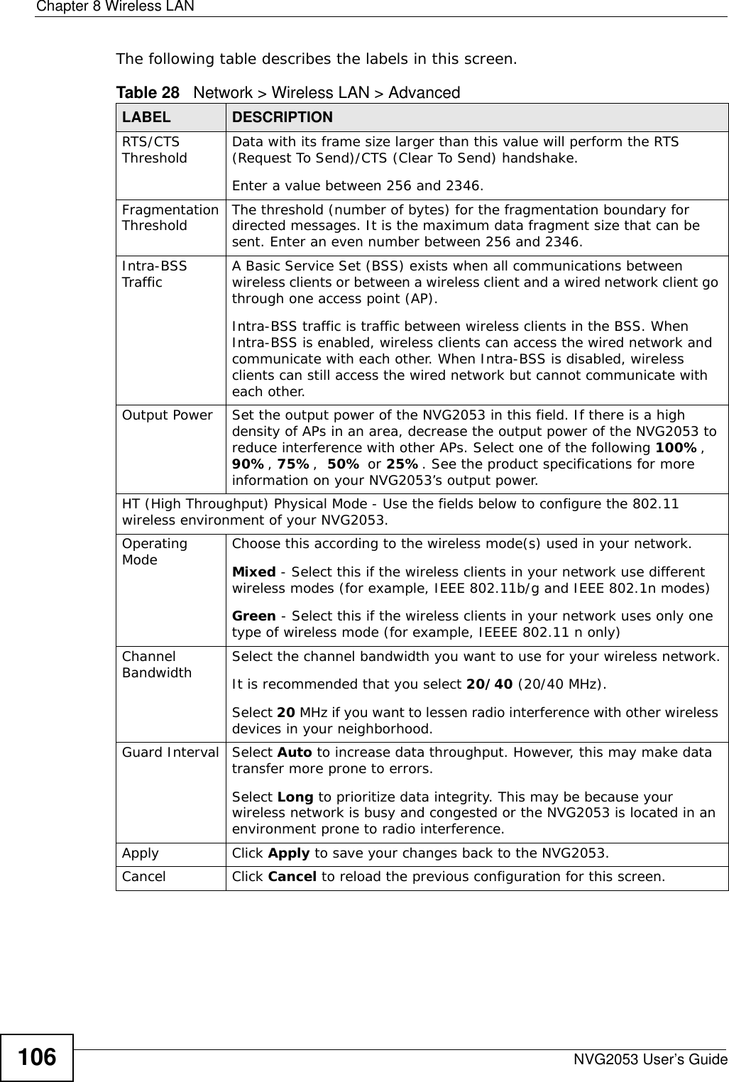
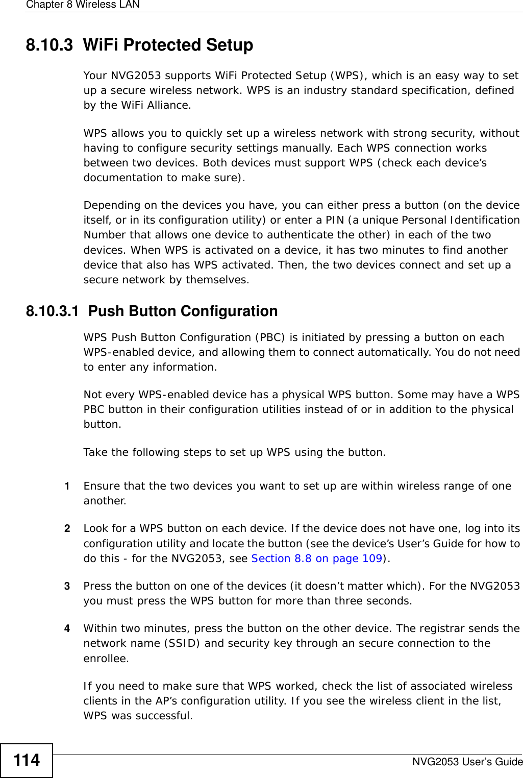
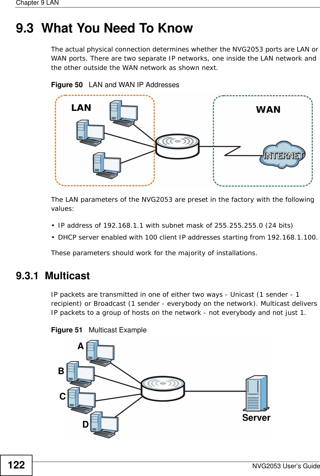
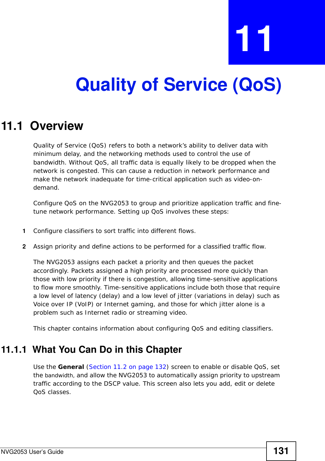
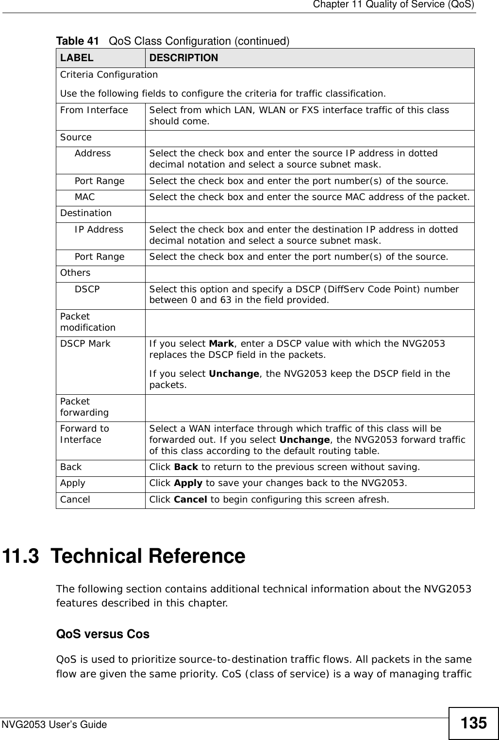
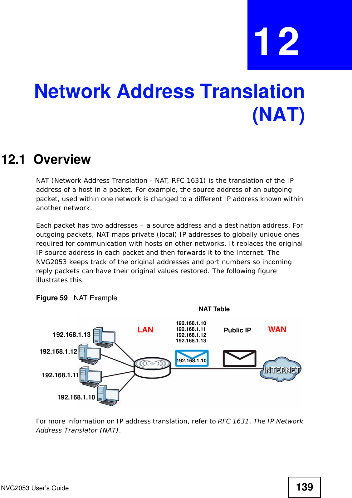
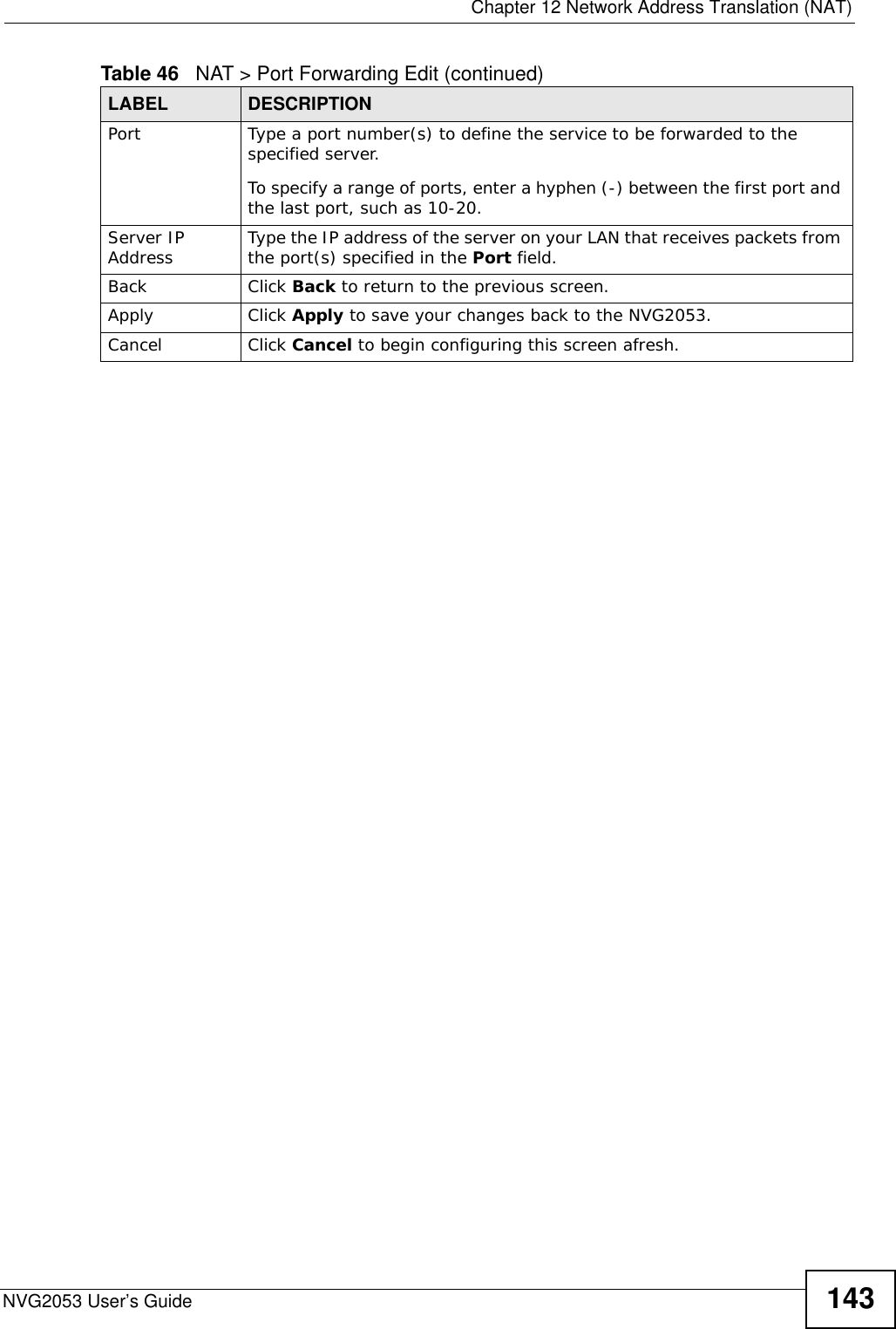
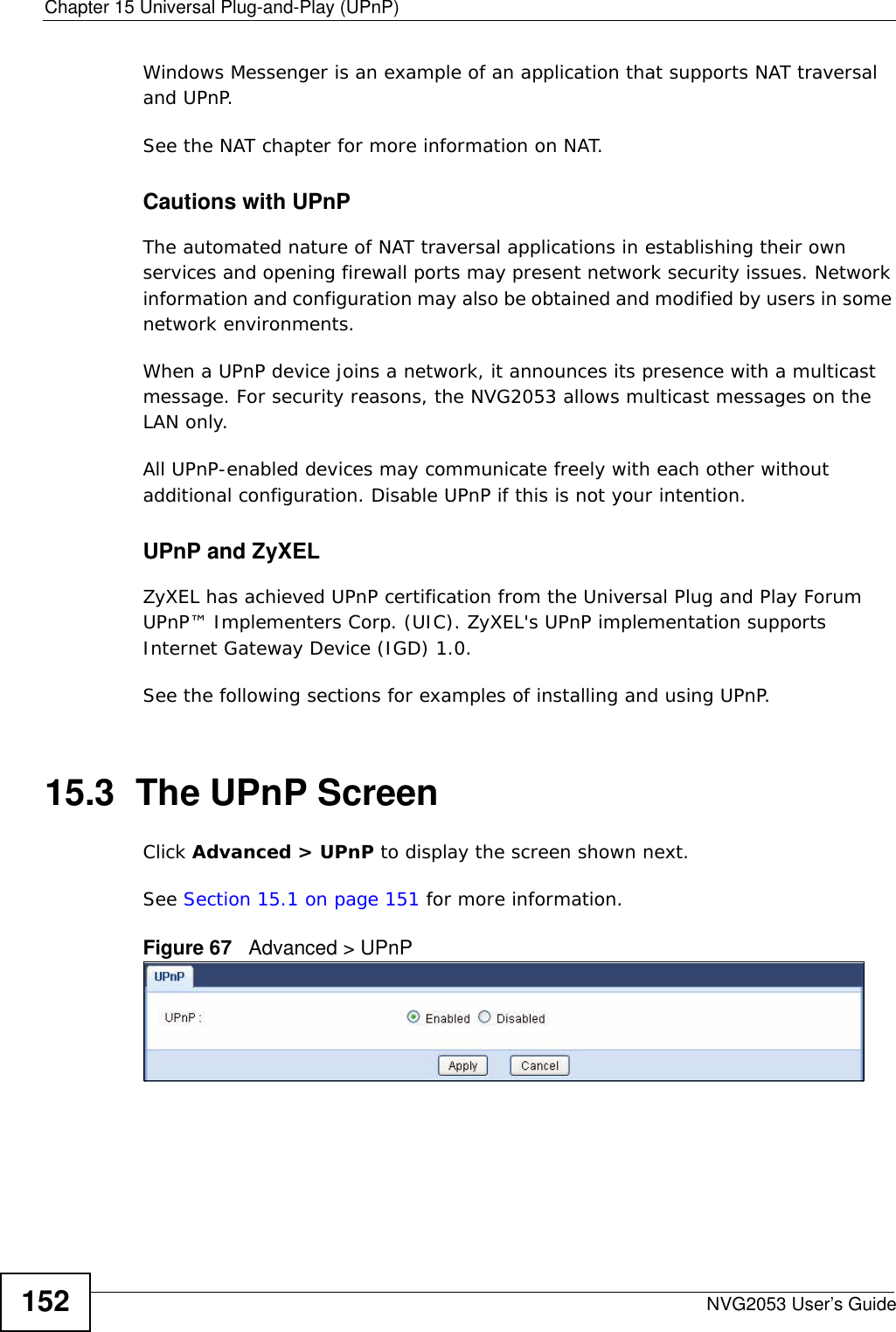
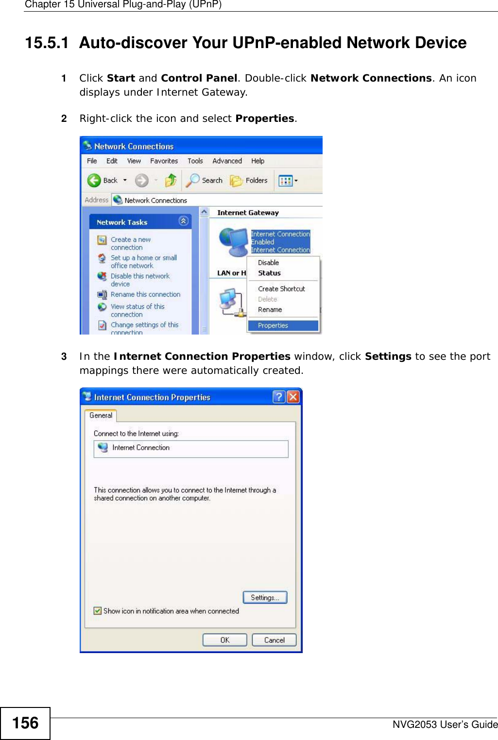
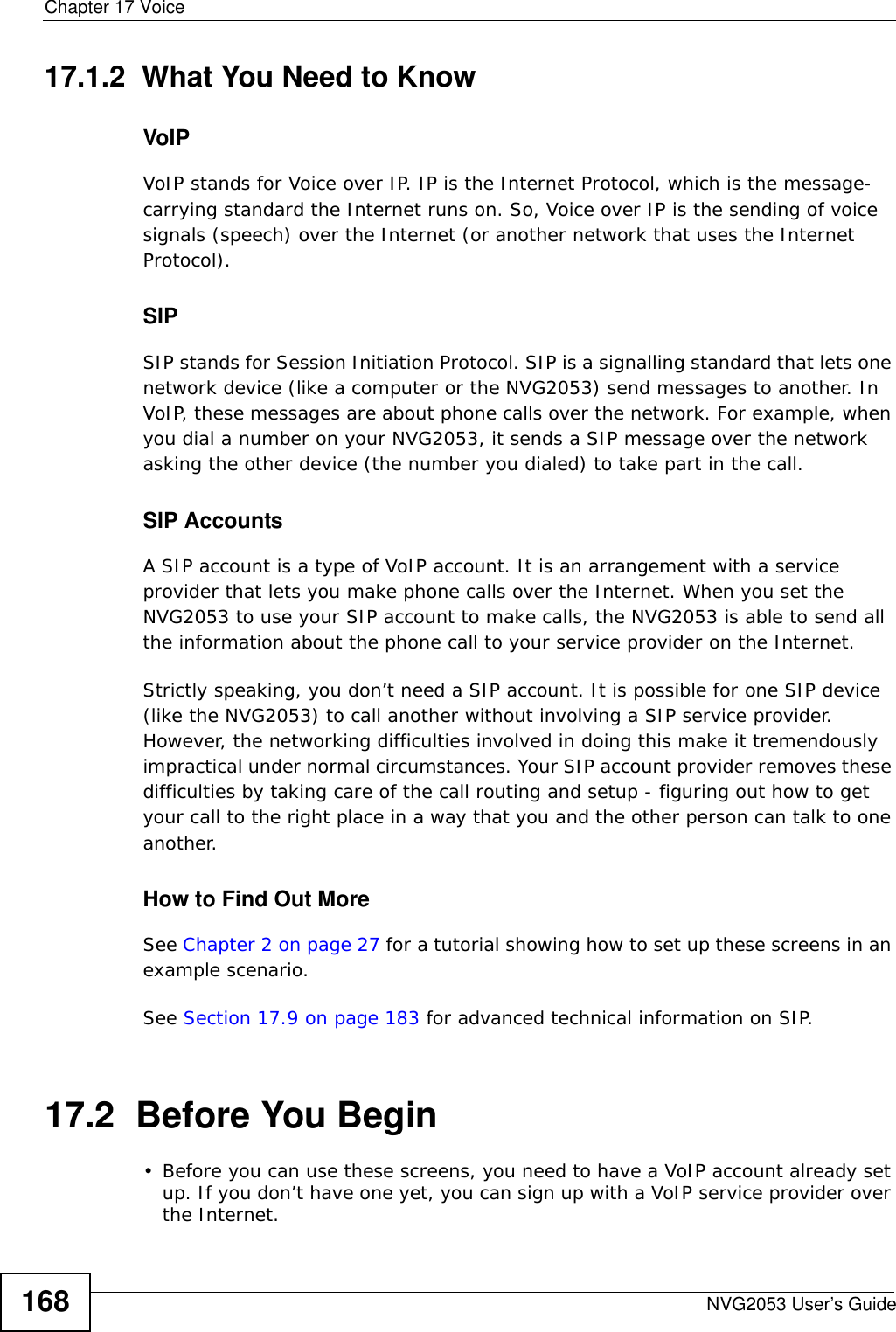
![Chapter 17 VoiceNVG2053 User’s Guide 177• Rules are separated by the | (bar) symbol.• “x” stands for a wildcard and can be any digit from 0 to 9.• A subset of keys is in a square bracket []. Ranges are allowed.For example, [359] means a number matching this rule can be 3, 5 or 9. [26-8*] means a number matching this rule can be 2, 6, 7, 8 or *.• The dot “.” appended to a digit allows the digit to be ignored or repeated multiple times. Any digit (0~9, *, #) after the dot will be ignored.For example, (01.) means a number matching this rule can be 0, 01, 0111, 01111, and so on.• <dialed-number:translated-number> indicates the number after the colon replaces the number before the colon in an angle bracket <>. For example, (<:1212> xxxxxxx) means the NVG2053 automatically prefixes the translated-number “1212” to the number you dialed before making the call. This can be used for local calls in the US.(<9:> xxx xxxxxxx) means the NVG2053 automatically removes the specified prefix “9” from the number you dialed before making the call. This is always used for making outside calls from an office. (xx<123:456>xxxx) means the NVG2053 automatically translates “123” to “456” in the number you dialed before making the call.• Calls with a number followed by the exclamation mark “!” will be dropped.• Calls with a number followed by the termination character “@” will be made immediately. Any digit (0~9, *, #) after the @ character will be ignored.In this example dial plan (0 | [49]11 | 1 [2-9]xx xxxxxxx | 1 947 xxxxxxx !), you can dial “0” to call the local operator, call 411 or 911, or make a long distance call with an area code starting from 2 to 9 in the US. The calls with the area code 947 will be dropped.17.5 The Phone Device Screen Use this screen to view and control which SIP accounts each phone uses. To access this screen, click VoIP > Phone > Phone Device.Figure 74 VoIP > Phone > Phone Device](https://usermanual.wiki/ZyXEL-Communications/NVG2053.User-s-manual-1/User-Guide-1439016-Page-177.png)