ZyXEL Communications NWA1123AC 802.11 a/b/g/n/ac Dual-Radio Ceiling Mount PoE Access Point User Manual Book
ZyXEL Communications Corporation 802.11 a/b/g/n/ac Dual-Radio Ceiling Mount PoE Access Point Book
Contents
- 1. User Manual Part 1.pdf
- 2. User Manual Part 2.pdf
User Manual Part 1.pdf

Quick Start Guide
www.zyxel.com
NWA1120 Series
Wireless LAN Ceiling Mountable PoE Access Point
Version 1.00
Edition 2, 10/2013
Copyright © 2012 ZyXEL Communications Corporation
User’s Guide
Default Login Details
LAN IP Address http://192.168.1.2
User Name admin
Password 1234

NWA1120 Series User’s Guide2
IMPORTANT!
READ CAREFULLY BEFORE USE.
KEEP THIS GUIDE FOR FUTURE REFERENCE.
This is a User’s Guide for a series of products. Not all products support all firmware features.
Screenshots and graphics in this book may differ slightly from your product due to differences in
your product firmware or your computer operating system. Every effort has been made to ensure
that the information in this manual is accurate.
Related Documentation
•Quick Start Guide
The Quick Start Guide shows how to connect the NWA and access the Web Configurator.

Contents Overview
NWA1120 Series User’s Guide 3
Contents Overview
User’s Guide .........................................................................................................................................9
Introducing the NWA ...............................................................................................................................11
Introducing the Web Configurator ...........................................................................................................19
Dashboard ...............................................................................................................................................25
Tutorial ....................................................................................................................................................29
Technical Reference ..........................................................................................................................47
Monitor ....................................................................................................................................................49
Wireless LAN ..........................................................................................................................................55
LAN .........................................................................................................................................................91
VLAN .......................................................................................................................................................95
System ....................................................................................................................................................97
Log Settings .......................................................................................................................................... 111
Maintenance ..........................................................................................................................................115
Troubleshooting ....................................................................................................................................123

Contents Overview
NWA1120 Series User’s Guide
4

Table of Contents
NWA1120 Series User’s Guide 5
Table of Contents
Contents Overview ..............................................................................................................................3
Table of Contents .................................................................................................................................5
Part I: User’s Guide ...........................................................................................9
Chapter 1
Introducing the NWA ..........................................................................................................................11
1.1 Introducing the NWA .........................................................................................................................11
1.1.1 Dual-Band ................................................................................................................................11
1.2 Wireless Modes .................................................................................................................................12
1.2.1 MBSSID ...................................................................................................................................12
1.2.2 Wireless Client .........................................................................................................................13
1.2.3 Root AP ...................................................................................................................................15
1.2.4 Repeater ..................................................................................................................................15
1.3 Ways to Manage the NWA ................................................................................................................16
1.4 Configuring Your NWA’s Security Features .......................................................................................17
1.4.1 Control Access to Your Device ................................................................................................17
1.4.2 Wireless Security .....................................................................................................................17
1.5 Good Habits for Managing the NWA .................................................................................................17
1.6 Hardware Connections ......................................................................................................................18
1.7 LED ...................................................................................................................................................18
Chapter 2
Introducing the Web Configurator ....................................................................................................19
2.1 Overview ...........................................................................................................................................19
2.2 Accessing the Web Configurator .......................................................................................................19
2.3 Resetting the NWA ............................................................................................................................21
2.3.1 Methods of Restoring Factory-Defaults ...................................................................................21
2.4 Navigating the Web Configurator ......................................................................................................22
2.4.1 Title Bar ...................................................................................................................................22
2.4.2 Navigation Panel .....................................................................................................................23
2.4.3 Main Window ...........................................................................................................................24
Chapter 3
Dashboard...........................................................................................................................................25
3.1 The Dashboard Screen .....................................................................................................................25

Table of Contents
NWA1120 Series User’s Guide
6
Chapter 4
Tutorial.................................................................................................................................................29
4.1 How to Configure the Wireless LAN ..................................................................................................29
4.1.1 Choosing the Wireless Mode ...................................................................................................29
4.1.2 Further Reading .......................................................................................................................29
4.2 How to Configure Multiple Wireless Networks ..................................................................................29
4.2.1 Configure the SSID Profiles .....................................................................................................31
4.2.2 Configure the Standard Network .............................................................................................33
4.2.3 Configure the VoIP Network ....................................................................................................34
4.2.4 Configure the Guest Network ..................................................................................................36
4.2.5 Testing the Wireless Networks ................................................................................................38
4.3 NWA Setup in AP and Wireless Client Modes ..................................................................................38
4.3.1 Scenario ..................................................................................................................................38
4.3.2 Configuring the NWA in MBSSID or Root AP Mode ................................................................39
4.3.3 Configuring the NWA in Wireless Client Mode ........................................................................42
4.3.4 MAC Filter Setup .....................................................................................................................44
4.3.5 Testing the Connection and Troubleshooting ..........................................................................45
Part II: Technical Reference............................................................................ 47
Chapter 5
Monitor.................................................................................................................................................49
5.1 Overview ...........................................................................................................................................49
5.2 What You Can Do .............................................................................................................................49
5.3 View Logs .........................................................................................................................................49
5.4 Statistics ............................................................................................................................................50
5.5 Association List .................................................................................................................................51
5.6 Channel Usage .................................................................................................................................52
Chapter 6
Wireless LAN.......................................................................................................................................55
6.1 Overview ...........................................................................................................................................55
6.2 What You Can Do in this Chapter .....................................................................................................55
6.3 What You Need To Know ..................................................................................................................56
6.4 Wireless Settings Screen ..................................................................................................................60
6.4.1 Root AP Mode .........................................................................................................................61
6.4.2 Repeater Mode ........................................................................................................................65
6.4.3 Wireless Client Mode ...............................................................................................................68
6.4.4 MBSSID Mode .........................................................................................................................71
6.5 SSID Screen .....................................................................................................................................74
6.5.1 Configuring SSID .....................................................................................................................75

Table of Contents
NWA1120 Series User’s Guide 7
6.6 Wireless Security Screen ..................................................................................................................76
6.6.1 Security: WEP .........................................................................................................................78
6.6.2 Security: WPA, WPA2, WPA2-MIX ..........................................................................................79
6.6.3 Security: WPA-PSK, WPA2-PSK, WPA2-PSK-MIX .................................................................81
6.7 RADIUS Screen ................................................................................................................................82
6.8 Layer-2 Isolation ................................................................................................................................84
6.8.1 Layer-2 Isolation Screen ..........................................................................................................85
6.9 MAC Filter Screen .............................................................................................................................86
6.10 Technical Reference ........................................................................................................................88
6.10.1 Additional Wireless Terms .....................................................................................................89
6.10.2 WMM QoS .............................................................................................................................89
6.10.3 Security Mode Guideline .......................................................................................................90
Chapter 7
LAN ......................................................................................................................................................91
7.1 Overview ...........................................................................................................................................91
7.2 What You Can Do in this Chapter .....................................................................................................91
7.3 What You Need to Know ...................................................................................................................91
7.4 LAN IP Screen ..................................................................................................................................93
Chapter 8
VLAN....................................................................................................................................................95
8.1 Overview ...........................................................................................................................................95
8.1.1 What You Can Do in This Chapter ...........................................................................................95
8.2 What You Need to Know ...................................................................................................................95
8.3 VLAN Screen ....................................................................................................................................96
Chapter 9
System.................................................................................................................................................97
9.1 Overview ...........................................................................................................................................97
9.2 What You Can Do in this Chapter .....................................................................................................97
9.3 What You Need To Know ..................................................................................................................98
9.4 WWW Screen ..................................................................................................................................100
9.5 Certificates Screen ..........................................................................................................................101
9.6 Telnet Screen ..................................................................................................................................102
9.7 SNMP Screen .................................................................................................................................104
9.8 FTP Screen .....................................................................................................................................106
9.9 Technical Reference ........................................................................................................................107
9.9.1 MIB ........................................................................................................................................107
9.9.2 Supported MIBs .....................................................................................................................108
9.9.3 Private-Public Certificates .....................................................................................................108
9.9.4 Certification Authorities ..........................................................................................................108
9.9.5 Checking the Fingerprint of a Certificate on Your Computer .................................................109

Table of Contents
NWA1120 Series User’s Guide
8
Chapter 10
Log Settings...................................................................................................................................... 111
10.1 Overview ....................................................................................................................................... 111
10.2 What You Can Do in this Chapter ................................................................................................. 111
10.3 What You Need To Know .............................................................................................................. 112
10.4 Log Settings Screen ...................................................................................................................... 112
Chapter 11
Maintenance......................................................................................................................................115
11.1 Overview .......................................................................................................................................115
11.2 What You Can Do in this Chapter .................................................................................................. 115
11.3 What You Need To Know ............................................................................................................... 116
11.4 General Screen .............................................................................................................................116
11.5 Password Screen .......................................................................................................................... 117
11.6 Time Screen .................................................................................................................................. 118
11.7 Firmware Upgrade Screen ............................................................................................................ 119
11.8 Configuration File Screen ..............................................................................................................120
11.8.1 Backup Configuration ...........................................................................................................120
11.8.2 Restore Configuration ..........................................................................................................120
11.8.3 Back to Factory Defaults ......................................................................................................121
11.9 Restart Screen ..............................................................................................................................121
Chapter 12
Troubleshooting................................................................................................................................123
12.1 Power, Hardware Connections, and LEDs ....................................................................................123
12.2 NWA Access and Login ................................................................................................................124
12.3 Internet Access .............................................................................................................................125
12.4 Wireless LAN ................................................................................................................................126
Appendix A Setting Up Your Computer’s IP Address ......................................................................129
Appendix B Pop-up Windows, JavaScript and Java Permissions ...................................................157
Appendix C IP Addresses and Subnetting.......................................................................................169
Appendix D IPv6..............................................................................................................................177
Appendix E Wireless LANs..............................................................................................................187
Appendix F Customer Support ........................................................................................................201
Appendix G Legal Information .........................................................................................................207
Index ..................................................................................................................................................213

9
PART I
User’s Guide

10

NWA1120 Series User’s Guide 11
CHAPTER 1
Introducing the NWA
This chapter introduces the main applications and features of the NWA. It also discusses the ways
you can manage your NWA.
1.1 Introducing the NWA
This User’s Guide covers the following models: NWA1121-NI, NWA1123-NI and NWA1123-AC. Your
NWA is an IPv6 wireless AP (Access Point) that can function in several wireless modes. It extends
the range of your existing wired network without additional wiring, providing easy network access
to mobile users.
The NWA controls network access with MAC address filtering and RADIUS server authentication. It
also provides a high level of network traffic security, supporting IEEE 802.1x, Wi-Fi Protected
Access (WPA), WPA2 and WEP data encryption. Its Quality of Service (QoS) features allow you to
prioritize time-sensitive or highly important applications such as VoIP.
Your NWA is easy to install, configure and use. The embedded Web-based configurator enables
simple, straightforward management and maintenance.
See the Quick Start Guide for instructions on how to make hardware connections.
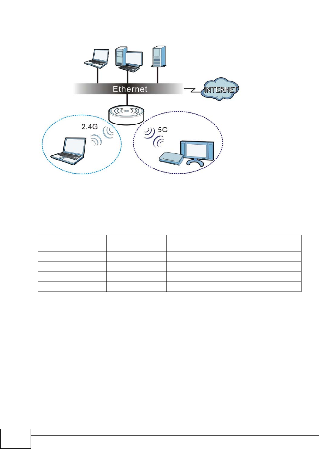
1.1.1 Dual-Band
The NWA1123-NI or NWA1123-AC is a dual-band AP and able to function both 2.4G and 5G
networks at the same time. You could use the 2.4 GHz band for regular Internet surfing and
Table 1 NWA Series Comparison Table
FEATURES NWA1121-NI NWA1123-NI NWA1123-AC
Supported Wireless Standards
IEEE 802.11b
IEEE 802.11g
IEEE 802.11n
IEEE 802.11a
IEEE 802.11b
IEEE 802.11g
IEEE 802.11n
IEEE 802.11a
IEEE 802.11ac
IEEE 802.11b
IEEE 802.11g
IEEE 802.11n
Supported Frequency Bands 2.4 GHz 2.4 GHz
5 GHz 2.4 GHz
5 GHz
Available Security Modes None
WEP
WPA
WPA2
WPA2-MIX
WPA-PSK
WPA2-PSK
WPA2-PSK-MIX
None
WEP
WPA
WPA2
WPA2-MIX
WPA-PSK
WPA2-PSK
WPA2-PSK-MIX
None
WEP
WPA
WPA2
WPA2-MIX
WPA-PSK
WPA2-PSK
WPA2-PSK-MIX
Number of SSID Profiles 8 32 32
Layer-2 Isolation Yes Yes Yes
Chapter 1 Introducing the NWA
NWA1120 Series User’s Guide
12
downloading while using the 5 GHz band for time sensitive traffic like high-definition video, music,
and gaming.
Figure 1 Dual-Band Application
1.2 Wireless Modes
The NWA can be configured to use the following WLAN operating modes:
Applications for each operating mode are shown below.
1.2.1 MBSSID
A Basic Service Set (BSS) is the set of devices forming a single wireless network (usually an access
point and one or more wireless clients). The Service Set IDentifier (SSID) is the name of a BSS. In
Multiple BSS (MBSSID) mode, the NWA provides multiple virtual APs, each forming its own BSS and
using its own individual SSID profile.
You can configure multiple SSID profiles, and have all of them active at any one time.
You can assign different wireless and security settings to each SSID profile. This allows you to
compartmentalize groups of users, set varying access privileges, and prioritize network traffic to
and from certain BSSs.
OPERATING MODE NUMBER OF
SUPPORTED SSID UNIVERSAL
REPEATER FUNCTION AP FUNCTION
MBSSID 8 No Yes
Client 1 No No
Root AP 5 Yes Yes
Repeater 1 Yes Yes
Chapter 1 Introducing the NWA
NWA1120 Series User’s Guide 13
To the wireless clients in the network, each SSID appears to be a different access point. As in any
wireless network, clients can associate only with the SSIDs for which they have the correct security
settings.
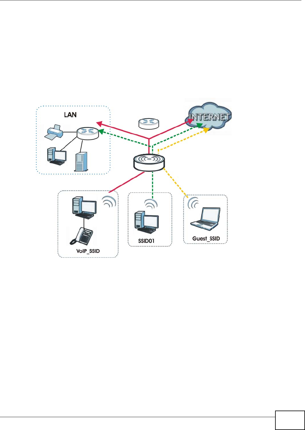
For example, you might want to set up a wireless network in your office where Internet telephony
(VoIP) users have priority. You also want a regular wireless network for standard users, as well as a
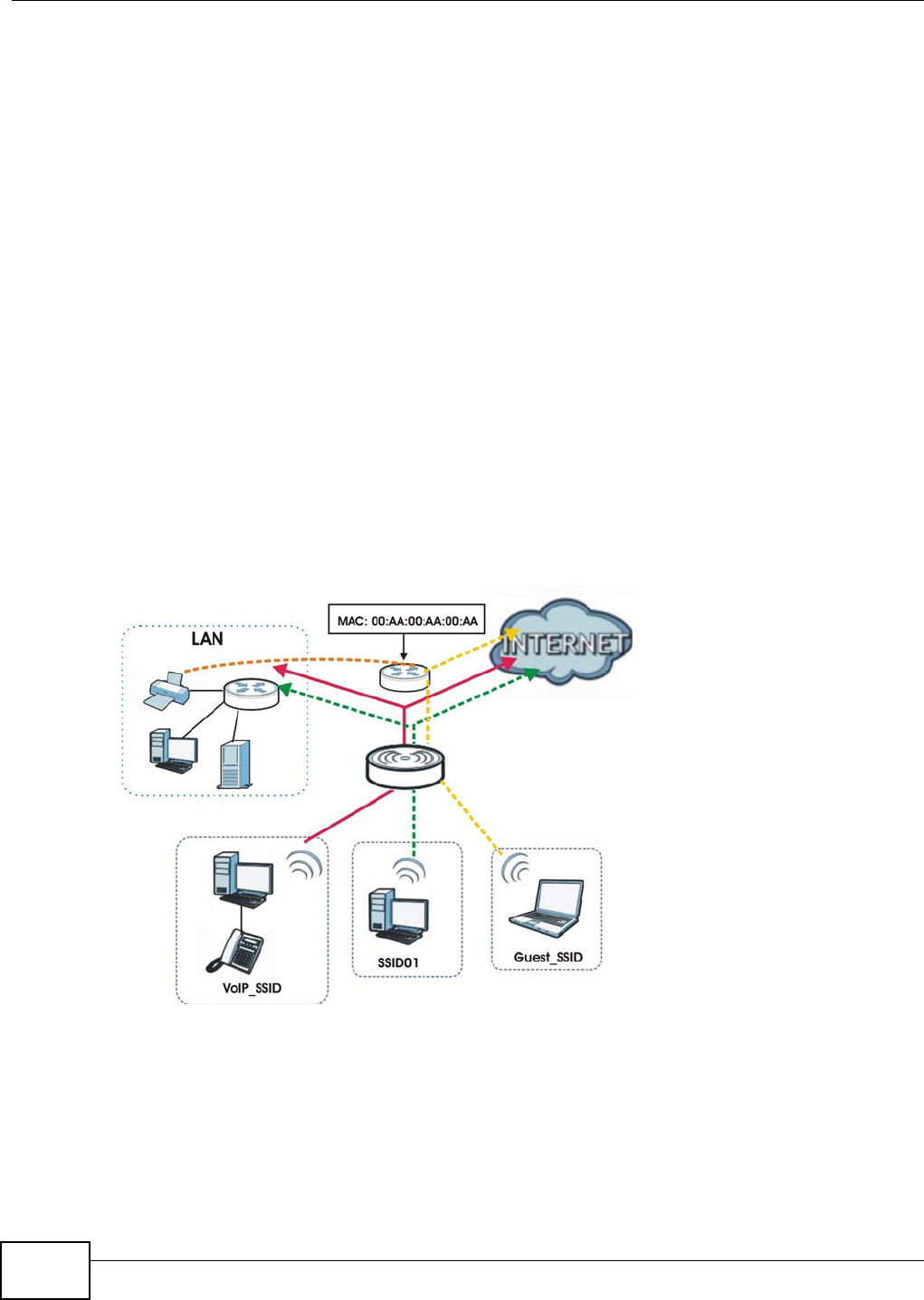
‘guest’ wireless network for visitors. In the following figure, VoIP_SSID users have QoS priority,
SSID01 is the wireless network for standard users, and Guest_SSID is the wireless network for
guest users. In this example, the guest user is forbidden access to the wired Land Area Network
(LAN) behind the AP and can access only the Internet.
Figure 2 Multiple BSSs
1.2.2 Wireless Client
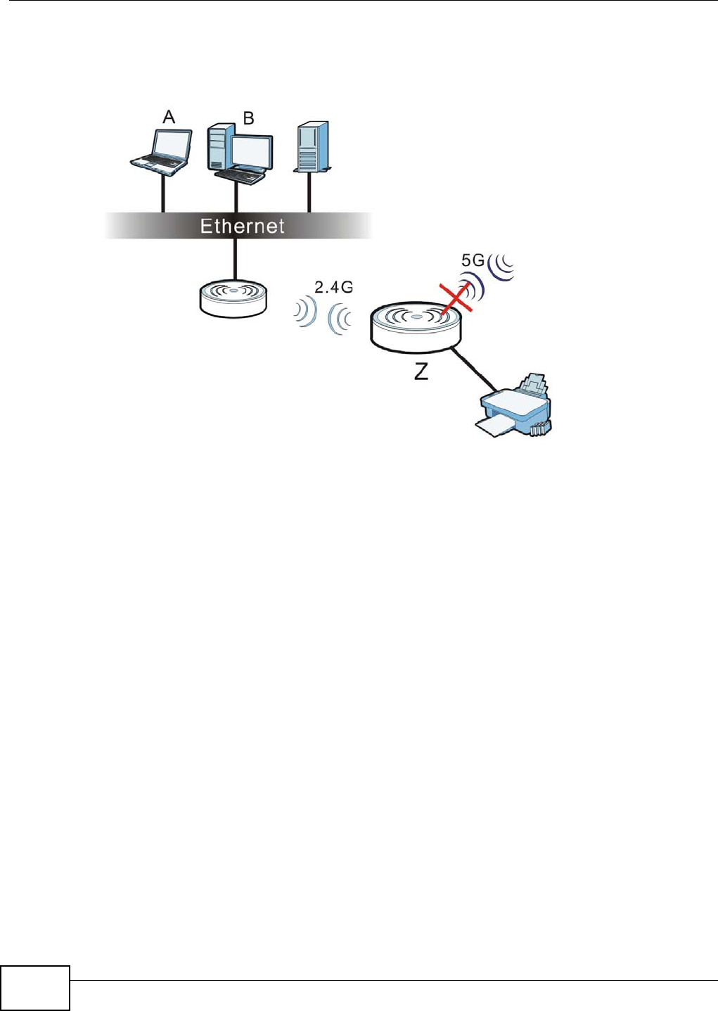
The NWA can be used as a wireless client to communicate with an existing network.
Note: The NWA1123-NI or NWA1123-AC is a dual-band AP which contains two different
types of wireless radios to transmit at 2.4 GHz and 5 GHz bands separately and
simultaneously. If one of the NWA1123-NI wireless radio is set to work in client
mode, the other radio will be disabled automatically.
Chapter 1 Introducing the NWA
NWA1120 Series User’s Guide
14
In the figure below, the printer can receive requests from the wired computer clients A and B via
the NWA in Client mode (Z) using only the 2.4 GHz band.
Figure 3 Wireless Client Application
Chapter 1 Introducing the NWA
NWA1120 Series User’s Guide 15
1.2.3 Root AP
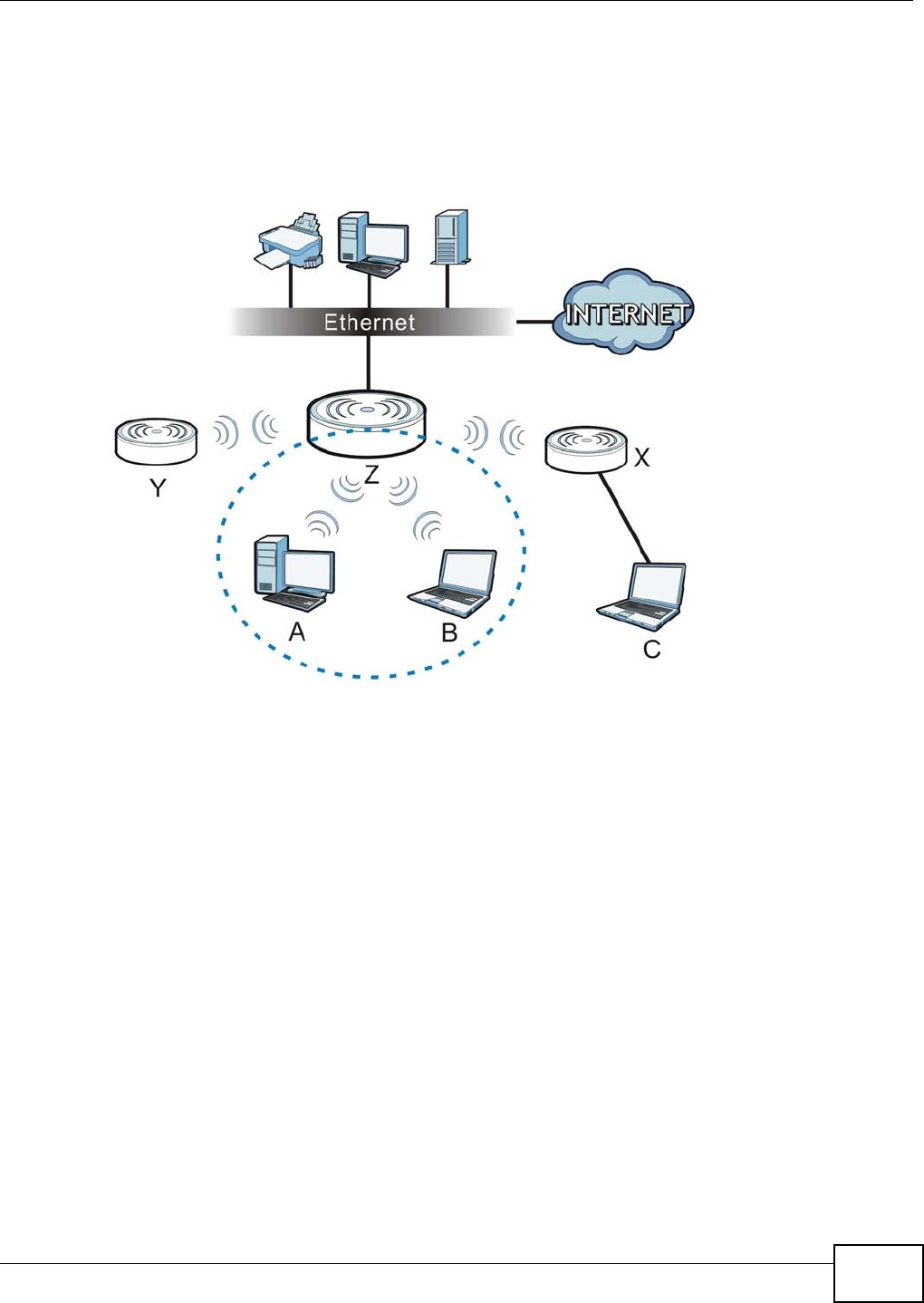
In Root AP mode, the NWA (Z) can act as the root AP in a wireless network and also allow repeaters
(X and Y) to extend the range of its wireless network at the same time. In the figure below, both
clients A, B and C can access the wired network through the root AP.
Figure 4 Root AP Application
On the NWA in Root AP mode, you can have multiple SSIDs active for reqular wireless connections
and one SSID for the connection with a repeater (universal repeater SSID). Wireless clients can use
either SSID to associate with the NWA in Root AP mode. A repeater must use the universal repeater
SSID to connect to the NWA in Root AP mode.
When the NWA is in Root AP mode, universal repeater security between the NWA and other
repeater is independent of the security between the wireless clients and the AP or repeater. If you
do not enable universal repeater security, traffic between APs is not encrypted. When universal
repeater security is enabled, both APs and repeaters must use the same pre-shared key. See
Section 6.6 on page 76 for more details.
Unless specified, the term “security settings” refers to the traffic between the wireless clients and
the AP. At the time of writing, universal repeater security is compatible with the NWA only.
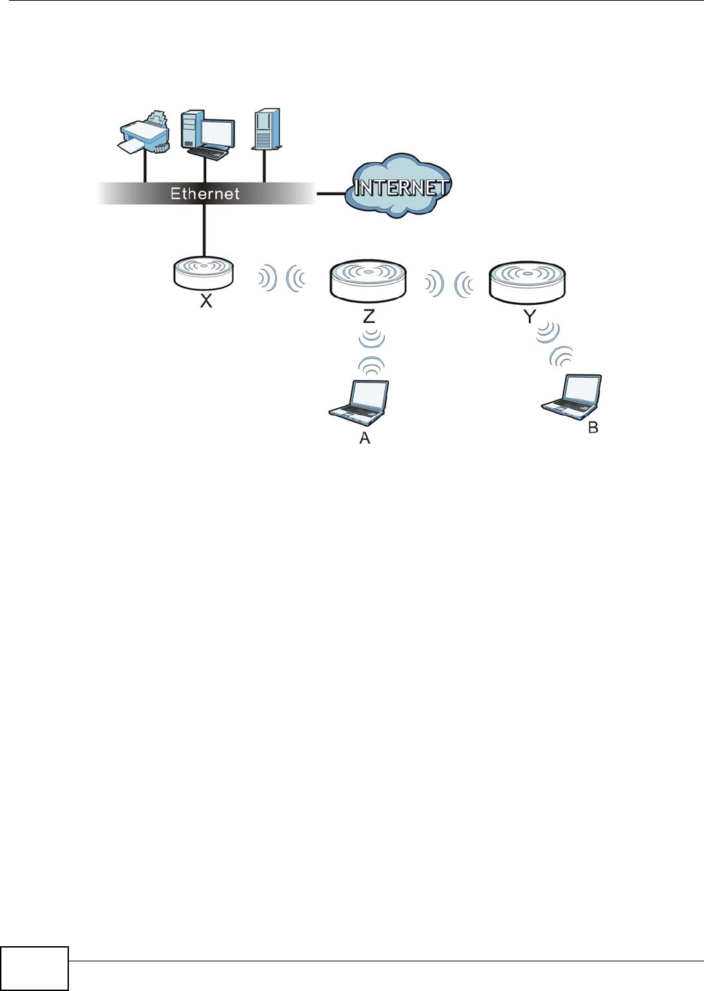
1.2.4 Repeater
The NWA can act as a wireless network repeater to extend a root AP’s wireless network range, and
also establish wireless connections with wireless clients.
Using Repeater mode, your NWA can extend the range of the WLAN. In the figure below, the NWA
in Repeater mode (Z) has a wireless connection to the NWA in Root AP mode (X) which is
connected to a wired network and also has a wireless connection to another NWA in Repeater mode
(Y) at the same time. Z and Y act as repeaters that forward traffic between associated wireless
Chapter 1 Introducing the NWA
NWA1120 Series User’s Guide
16
clients and the wired LAN. Clients A and B access the AP and the wired network behind the AP
throught repeaters Z and Y.
Figure 5 Repeater Application
When the NWA is in Repeater mode, universal repeater security between the NWA and other
repeater is independent of the security between the wireless clients and the AP or repeater. If you
do not enable universal repeater security, traffic between APs is not encrypted. When universal
repeater security is enabled, both APs and repeaters must use the same pre-shared key. See
Section 6.6 on page 76 for more details.
Once the security settings of peer sides match one another, the connection between devices is
made.
At the time of writing, universal repeater security is compatible with the NWA only.
1.3 Ways to Manage the NWA
Use any of the following methods to manage the NWA.
• Web Configurator. This is recommended for everyday management of the NWA using a
(supported) web browser.
• FTP (File Transfer Protocol) for firmware upgrades and configuration backup and restore.
• SNMP (Simple Network Management Protocol). The device can be monitored by an SNMP
manager.

Chapter 1 Introducing the NWA
NWA1120 Series User’s Guide 17
1.4 Configuring Your NWA’s Security Features
Your NWA comes with a variety of security features. This section summarizes these features and
provides links to sections in the User’s Guide to configure security settings on your NWA. Follow the
suggestions below to improve security on your NWA and network.
1.4.1 Control Access to Your Device
Ensure only people with permission can access your NWA.
• Control physical access by locating devices in secure areas, such as locked rooms. Most NWAs
have a reset button. If an unauthorized person has access to the reset button, they can then
reset the device’s password to its default password, log in and reconfigure its settings.
• Change any default passwords on the NWA, such as the password used for accessing the NWA’s
web configurator (if it has a web configurator). Use a password with a combination of letters and
numbers and change your password regularly. Write down the password and put it in a safe
place.
•See Section 11.5 on page 117 for instructions on changing your password.
• Configure remote management to control who can manage your NWA. See Chapter 9 on page 97
for more information. If you enable remote management, ensure you have enabled remote
management only on the IP addresses, services or interfaces you intended and that other remote
management settings are disabled.
1.4.2 Wireless Security
Wireless devices are especially vulnerable to attack. Take the following measures to improve
wireless security.
• Enable wireless security on your NWA. Choose the most secure encryption method that all
devices on your network support. See Section 6.6 on page 76 for directions on configuring
encryption. If you have a RADIUS server, enable IEEE 802.1x or WPA(2) user identification on
your network so users must log in. This method is more common in business environments.
• Hide your wireless network name (SSID). The SSID can be regularly broadcast and unauthorized
users may use this information to access your network. See Section 6.5 on page 74 for directions
on using the web configurator to hide the SSID.
• Enable the MAC filter to allow only trusted users to access your wireless network or deny
unwanted users access based on their MAC address. See Section 6.9 on page 86 for directions on
configuring the MAC filter.
1.5 Good Habits for Managing the NWA
Do the following things regularly to make the NWA more secure and to manage it more effectively.
• Change the password. Use a password that’s not easy to guess and that consists of different
types of characters, such as numbers and letters.
• Write down the password and put it in a safe place.
Chapter 1 Introducing the NWA
NWA1120 Series User’s Guide
18
• Back up the configuration (and make sure you know how to restore it). Restoring an earlier
working configuration may be useful if the device becomes unstable or even crashes. If you
forget your password, you will have to reset the NWA to its factory default settings. If you backed
up an earlier configuration file, you would not have to totally re-configure the NWA. You could
simply restore your last configuration.
1.6 Hardware Connections
See your Quick Start Guide for information on making hardware connections.
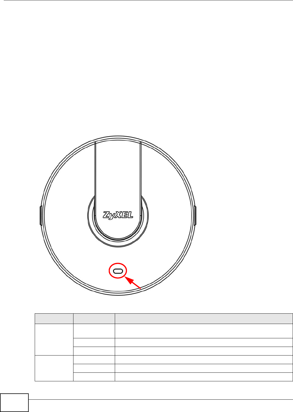
1.7 LED
Figure 6 LED
Table 2 LED
COLOR STATUS DESCRIPTION
Amber On There is system error and the NWA cannot boot up, or the NWA doesn’t
have an Ethernet connection with the LAN.
Flashing The NWA is starting up.
Off The NWA is receiving power and ready for use.
Green On The WLAN is active.
Blinking The WLAN is active, and transmitting or receiving data.
Off The WLAN is not active.

NWA1120 Series User’s Guide 19
CHAPTER 2
Introducing the Web Configurator
This chapter describes how to access the NWA’s web configurator and provides an overview of its
screens.
2.1 Overview
The NWA Web Configurator allows easy management using an Internet browser.
In order to use the Web Configurator, you must:
•Use Internet Explorer 7.0 and later versions, Mozilla Firefox 9.0 and later versions, Safari 4.0 and
later versions, or Google Chrome 10.0 and later versions.
•Allow pop-up windows.
•Enable JavaScript (enabled by default).
•Enable Java permissions (enabled by default).
•Enable cookies.
The recommended screen resolution is 1024 x 768 pixels and higher.
2.2 Accessing the Web Configurator
1Make sure your hardware is properly connected and prepare your computer or computer network to
connect to the NWA (refer to the Quick Start Guide).
2Launch your web browser.
Chapter 2 Introducing the Web Configurator
NWA1120 Series User’s Guide
20
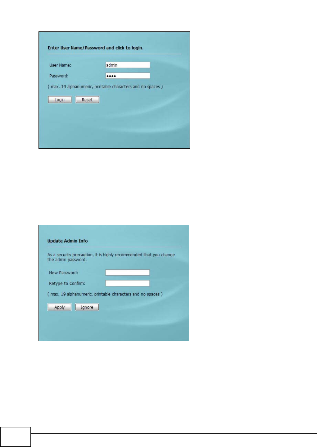
3Type "192.168.1.2" as the URL (default). The login screen appears.
Figure 7 The Login Screen
4Type “admin” as the (default) username and “1234” as the (default) password. Click Login.
5You should see a screen asking you to change your password (highly recommended) as shown
next. Type a new password (and retype it to confirm) then click Apply. Alternatively, click Ignore.
Note: If you do not change the password, the following screen appears every time you
login.
Figure 8 Change Password Screen
You should now see the Dashboard screen. See Chapter 2 on page 19 for details about the
Dashboard screen.
Chapter 2 Introducing the Web Configurator
NWA1120 Series User’s Guide 21
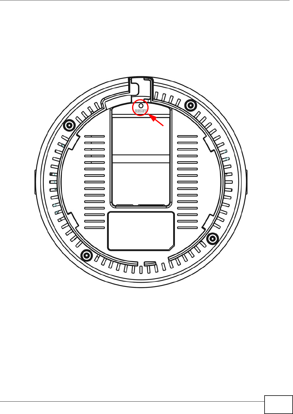
2.3 Resetting the NWA
If you forget your password or cannot access the web configurator, you will need to use the RESET
button at the rear panel of the NWA. This replaces the current configuration file with the factory-
default configuration file. This means that you will lose all the settings you previously configured.
The password will be reset to “1234”.
Figure 9 The RESET Button
2.3.1 Methods of Restoring Factory-Defaults
You can erase the current configuration and restore factory defaults in two ways:
Use the RESET button to upload the default configuration file. Hold this button in for about 3
seconds (the light will begin to blink). Use this method for cases when the password or IP address
of the NWA is not known.
Use the web configurator to restore defaults (refer to Section 11.8 on page 120).
Chapter 2 Introducing the Web Configurator
NWA1120 Series User’s Guide
22
2.4 Navigating the Web Configurator
The following summarizes how to navigate the web configurator from the Dashboard screen. This
guide uses the NWA1121-NI screens as an example. The screens may vary slightly for different
models.
Figure 10 Status Screen of the Web Configurator
As illustrated above, the Web Configurator screen is divided into these parts:
•A - title bar
•B - navigation panel
•C - main window
2.4.1 Title Bar
Click Logout at any time to exit the Web Configurator.
Click ZAbout to open the about window, which provides information of the boot module and driver
versions.
A
BC

Chapter 2 Introducing the Web Configurator
NWA1120 Series User’s Guide 23
2.4.2 Navigation Panel
Use the menu items on the navigation panel to open screens to configure NWA features. The
following tables describe each menu item.
Table 3 Navigation Panel Summary
LINK TAB FUNCTION
Dashboard This screen shows the NWA’s general device and network status
information. Use this screen to access the statistics and client list.
Monitor
Logs View Log Use this screen to view the logs for the categories that you selected.
Statistics Use this screen to view port status, packet specific statistics, the
"system up time" and so on.
Association List Use this screen to view the wireless stations that are currently
associated to the NWA.
Channel Usage Use this screen to know whether a channel is used by another
wireless network or not.
Configuration
Network
Wireless LAN Wireless
Settings
Wireless
Settings - 2.4G
Wireless
Settings - 5G
Use this screen to configure the wireless LAN settings and NWA’s
operation mode.
SSID Use this screen to configure up to eight SSID profiles for your NWA.
Security Use this screen to configure wireless security profiles on the NWA.
RADIUS Use this screen to configure up to four RADIUS profiles.
Layer-2 Isolation Use this screen to configure the MAC addresses of the devices that
you want to allow the associated wireless clients to have access to
when layer-2 isolation is enabled
MAC Filter Use this screen to configure MAC filtering profiles.
LAN IP Use this screen to configure the NWA’s LAN IP address.
VLAN Use this screen to configure the NWA’s VLAN settings.
System WWW Use this screen to configure through which interface(s) and from
which IP address(es) users can use HTTP to manage the NWA.
Certificates Use this screen to import or remove a certificate from the NWA.
Telent Use this screen to configure through which interface(s) and from
which IP address(es) users can use Telnet to manage the NWA.
SNMP Use this screen to configure the NWA for SNMP management.
FTP Use this screen to configure through which interface(s) and from
which IP address(es) users can use FTP to access the NWA.
Log Settings Use this screen to change your log settings.
Maintenance
General Use this screen to configure your device’s name.
Password Use this screen to configure your device’s password.
Time Use this screen to change your NWA’s time and date.
Firmware Upgrade Use this screen to upload firmware to your device.

Chapter 2 Introducing the Web Configurator
NWA1120 Series User’s Guide
24
2.4.3 Main Window
The main window displays information and configuration fields. It is discussed in the rest of this
document.
Configuration File Use this screen to backup and restore your device’s configuration
(settings) or reset the factory default settings.
Restart Use this screen to reboot the NWA without turning the power off.
Table 3 Navigation Panel Summary
LINK TAB FUNCTION

NWA1120 Series User’s Guide 25
CHAPTER 3
Dashboard
The Dashboard screens display when you log into the NWA, or click Dashboard in the navigation
menu.
Use the Dashboard screen to look at the current status of the device, system resources, and
interfaces. The Dashboard screens also provide detailed information about system statistics,
associated wireless clients, and logs.
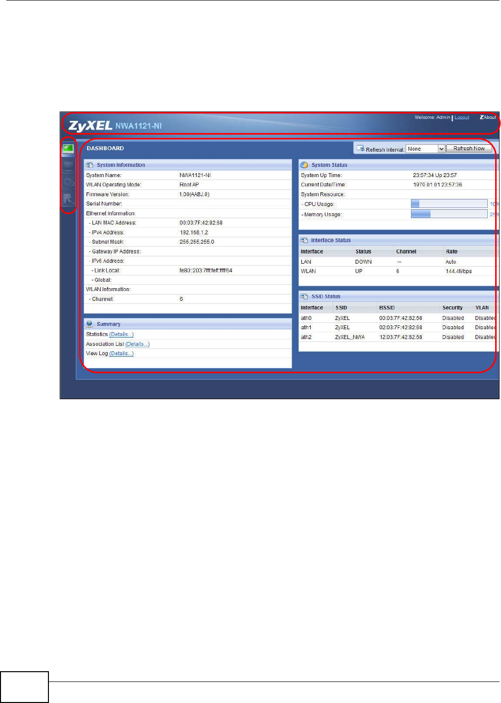
3.1 The Dashboard Screen
Use this screen to get a quick view of system, Ethernet, WLAN and other information regarding
your NWA.
Chapter 3 Dashboard
NWA1120 Series User’s Guide
26
Click Dashboard. The following screen displays.
Figure 11 The Dashboard Screen (NWA1121-NI)
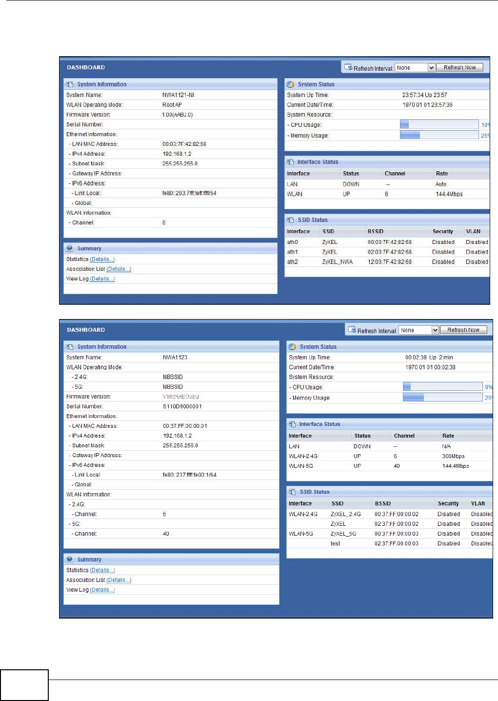
Figure 12 The Dashboard Screen (NWA1123-NI or NWA1123-AC)

Chapter 3 Dashboard
NWA1120 Series User’s Guide 27
The following table describes the labels in this screen.
Table 4 The Dashboard Screen
LABEL DESCRIPTION
Refresh Interval Select how often you want the NWA to update this screen.
Refresh Now Click this to update this screen immediately.
System Information
System Name This field displays the NWA system name. It is used for identification. You can
change this in the Maintenance > General screen’s System Name field.
WLAN Operating
Mode This field displays the current operating mode of the wireless module (Root AP,
Repeater, Client, or MBSSID). You can change the operating mode in the
Configuration > Wireless LAN > Wireless Settings screen.
2.4G This field displays the current operating mode of the 2.4G wireless module (Root
AP, Repeater, Client, or MBSSID). You can change the operating mode in the
Configuration > Wireless LAN > Wireless Settings - 2.4G screen.
5G This field displays the current operating mode of the 5G wireless module (Root AP,
Repeater, Client, or MBSSID). You can change the operating mode in the
Configuration > Wireless LAN > Wireless Settings - 5G screen.
Firmware Version This field displays the current version of the firmware inside the device. It also
shows the date the firmware version was created. You can change the firmware
version by uploading new firmware in Maintenance > Firmware Upgrade.
Serial Number This field displays the serial number of the NWA.
Ethernet Information
LAN MAC Address This displays the MAC (Media Access Control) address of the NWA on the LAN.
Every network device has a unique MAC address which identifies it across the
network.
IPv4 Address This field displays the current IPv4 address of the NWA on the network.
Subnet Mask Subnet masks determine the maximum number of possible hosts on a network.
You can also use subnet masks to divide one network into multiple sub-networks.
Gateway IP Address This is the IP address of the gateway. The gateway is a router or switch on the
same network segment as the device's LAN port. The gateway helps forward
packets to their destinations.
IPv6 Address This field displays the current IPv6 address(es) of the NWA on the network.
Link Local This is the IPv6 link-local address that the NWA generates automatically.
Global This is the NWA’s IPv6 global address that you specify manually in the
Configuration > LAN screen.
WLAN Information
SSID This field displays the SSID (Service Set Identifier). This is available only when the
WLAN operation mode is Client.
Channel The channel or frequency used by the NWA to send and receive information (in the
2.4G or 5G wireless network).
Status This shows the current status of the wireless LAN. This is available only when the
WLAN operation mode is Client.
Security Mode This displays the security mode the NWA is using. This is available only when the
WLAN operation mode is Client.
Summary
Statistics Click this link to view port status and packet specific statistics. See Section 5.4 on
page 50.
Association List Click this to see a list of wireless clients currently associated to each of the NWA’s
wireless modules. See Section 5.5 on page 51.

Chapter 3 Dashboard
NWA1120 Series User’s Guide
28
View Log Click this to see a list of logs produced by the NWA. See Section 5.3 on page 49.
System Status
System Up Time This field displays the elapsed time since the NWA was turned on.
Current Date/Time This field displays the date and time configured on the NWA. You can change this in
the Maintenance > Time screen.
System Resource
CPU Usage This field displays what percentage of the NWA’s processing ability is currently
being used. The higher the CPU usage, the more likely the NWA is to slow down.
Memory Usage This field displays what percentage of the NWA’s volatile memory is currently in
use. The higher the memory usage, the more likely the NWA is to slow down. Some
memory is required just to start the NWA and to run the web configurator.
Interface Status
Interface This column displays each interface of the NWA.
Status This field indicates whether or not the NWA is using the interface.
For each interface, this field displays Up when the NWA is using the interface and
Down when the NWA is not using the interface.
Channel This shows the channel number which the NWA is currently using over the wireless
LAN.
Rate For the LAN port this displays the port speed and duplex setting.
For the WLAN interface, it displays the downstream and upstream transmission
rate or N/A if the interface is not in use.
SSID Status This section is not available when the WLAN operation mode is Client.
Interface This column displays each of the NWA’s wireless interfaces.
SSID This field displays the SSID(s) currently used by each wireless module.
BSSID This field displays the MAC address of the wireless module.
Security This field displays the type of wireless security used by each SSID.
VLAN This field displays the VLAN ID of each SSID in use, or Disabled if the SSID does
not use VLAN.
Table 4 The Dashboard Screen (continued)
LABEL DESCRIPTION

NWA1120 Series User’s Guide 29
CHAPTER 4
Tutorial
This chapter first provides an overview of how to configure the wireless LAN on your NWA, and then
gives step-by-step guidelines showing how to configure your NWA for some example scenarios.
4.1 How to Configure the Wireless LAN
This section illustrates how to choose which wireless operating mode to use on the NWA and how to
set up the wireless LAN in each wireless mode. See Section 4.1.2 on page 29 for links to more
information on each step.
4.1.1 Choosing the Wireless Mode
•Use MBSSID (Multiple Basic Service Set Identifier) operating mode if you want to use the NWA
as an access point with some groups of users having different security or QoS settings from other
groups of users. See Section 1.2.1 on page 12 for details.
•Use Client operating mode if you want to use the NWA to access a wireless network. See Section
1.2.2 on page 13 for details.
•Use Root AP operating mode if you want to allow wireless clients to access your wired network
through the NWA and also have repeaters communicate with the NWA to expand wireleass
coverage. See Section 1.2.3 on page 15 for details.
•Use Repeater operating mode if you want to use the NWA to communicate with the root AP or
other repeaters. See Section 1.2.4 on page 15 for details.
4.1.2 Further Reading
Use these links to find more information on the steps:
• Choosing 802.11 Mode: see Section 6.4 on page 60.
• Choosing a wireless Channel ID: see Section 6.4 on page 60.
• Choosing a Security mode: see Section 6.6 on page 76.
• Configuring an external RADIUS server: see Section 6.7 on page 82.
•Configuring MAC Filtering: see Section 6.9 on page 86.
4.2 How to Configure Multiple Wireless Networks
In this example, you have been using your NWA as an access point for your office network. Now
your network is expanding and you want to make use of the MBSSID feature (see Section 6.4.4 on
Chapter 4 Tutorial
NWA1120 Series User’s Guide
30
page 71) to provide multiple wireless networks. Each wireless network will cater to a different type
of user.
You want to make three wireless networks: one standard office wireless network with all the same
settings you already have, another wireless network with high priority QoS settings for Voice over
IP (VoIP) users, and a guest network that allows visitors to access only the Internet and the
network printer.
To do this, you will take the following steps:
1Edit the SSID profiles.
2Change the operating mode from Root AP to MBSSID and reactivate the standard network.
3Configure different security modes for the networks.
4Configure a wireless network for standard office use.
5Configure a wireless network for VoIP users.
6Configure a wireless network for guests to your office.
The following figure shows the multiple networks you want to set up. Your NWA is marked Z, the
main network router is marked A, and your network printer is marked B.
The standard network (SSID01) has access to all resources. The VoIP network (VoIP_SSID) has
access to all resources and a high QoS priority. The guest network (Guest_SSID) has access to the
Internet and the network printer only, and a low QoS priority.
Z
A
B
Chapter 4 Tutorial
NWA1120 Series User’s Guide 31
To configure these settings, you need to know the Media Access Control (MAC) addresses of the
devices you want to allow users of the guest network to access. The following table shows the
addresses used in this example.
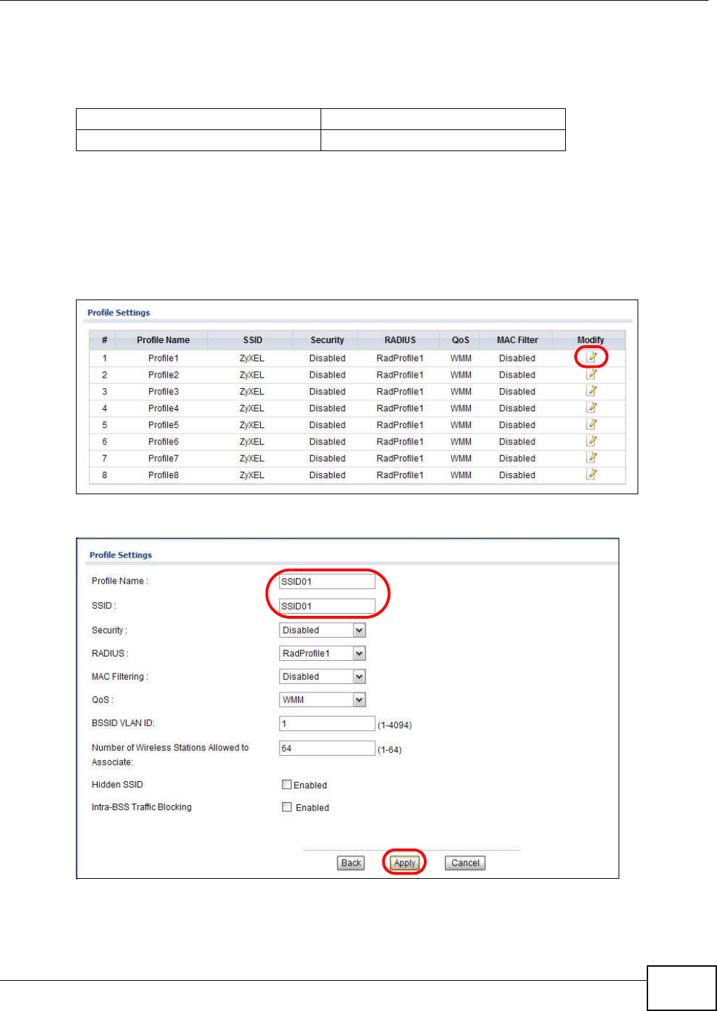
4.2.1 Configure the SSID Profiles
1Log in to the NWA (see Section 2.2 on page 19). Click Wireless LAN > SSID. The SSID screen
appears.
2Click the Edit icon next to the Profile1.
3Rename the Profile Name and SSID as SSID01. Click Apply.
4Repeat Step 2 and 3 to change Profile2 and Profile3 to VoIP_SSID and Guest_SSID.
Table 5 Tutorial: Example Information
Network router (A) MAC address 00:AA:00:AA:00:AA
Network printer (B) MAC address AA:00:AA:00:AA:00
Chapter 4 Tutorial
NWA1120 Series User’s Guide
32
4.2.1.1 MBSSID
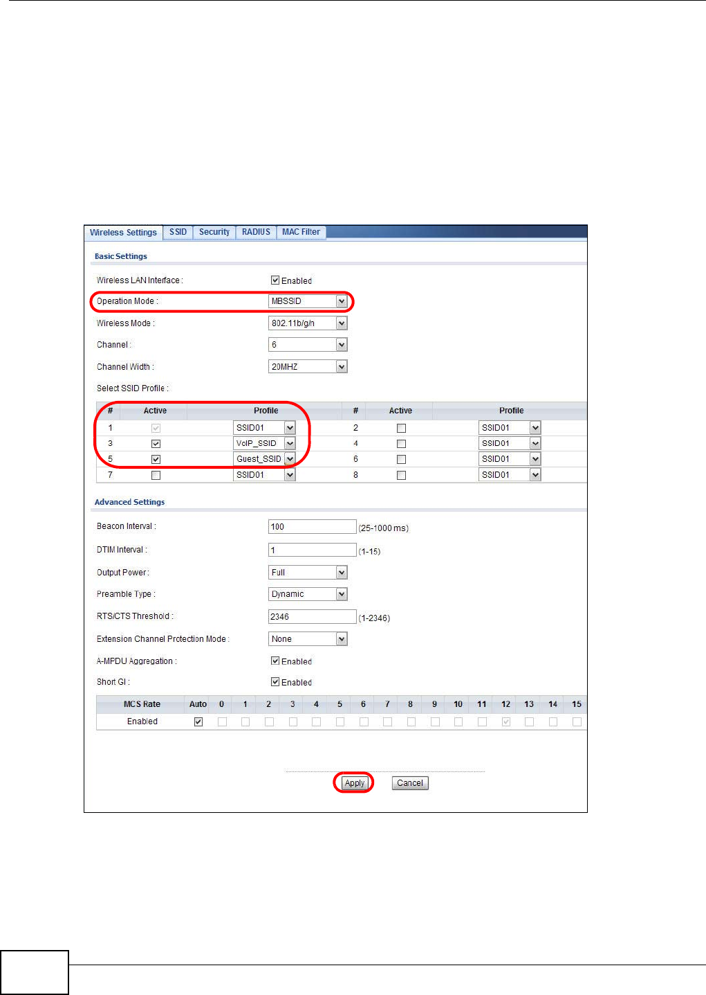
1Go to Wireless LAN > Wireless Settings. Select MBSSID from the Operation Mode drop-down
list box.
2SSID01 is the standard network, so select SSID01 as the first profile. It is always active.
3Select VoIP_SSID as the second profile, and Guest_SSID as the third profile. Select the
corresponding Active check-boxes.
4Click Apply to save your settings. Now the three SSIDs are activated.
Chapter 4 Tutorial
NWA1120 Series User’s Guide 33
4.2.2 Configure the Standard Network
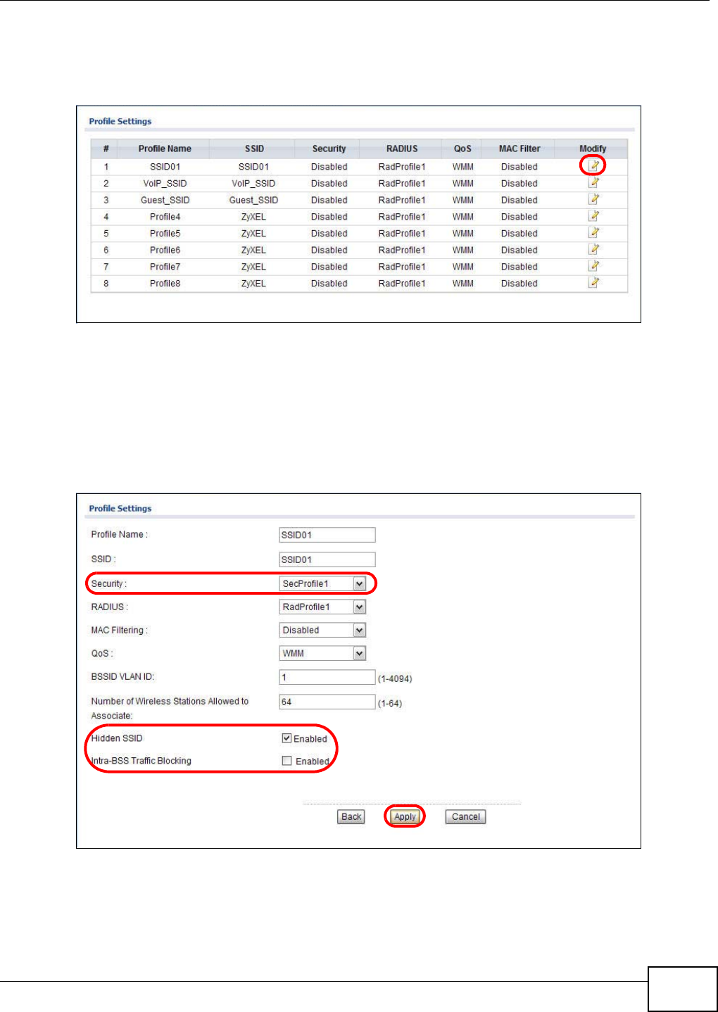
1Click Wireless LAN > SSID. Click the Edit icon next to SSID01.
2Select SecProfile1 as SSID01’s security profile. Select the Hidden SSID checkbox as you want
only authorized company employees to use this network, so there is no need to broadcast the SSID
to wireless clients scanning the area.
Also, the clients on SSID01 might need to access other clients on the same wireless network. Do
not select the Intra-BSS Traffic blocking check-box.
Click Apply.
Chapter 4 Tutorial
NWA1120 Series User’s Guide
34
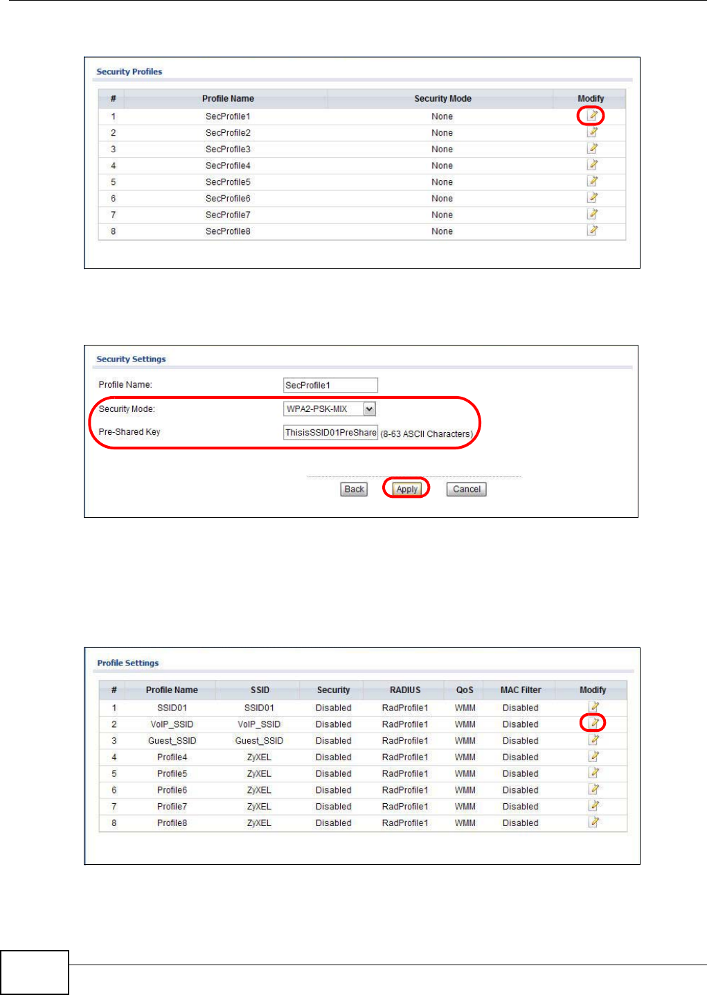
3Next, click Wireless LAN > Security. Click the Edit icon next to SecProfile1.
4Since SSID01 is the standard network that has access to all resources, assign a more secure
security mode. Select WPA2-PSK-MIX as the Security Mode, and enter the Pre-Shared Key. In
this example, use ThisisSSID01PreSharedKey. Click Apply.
5You have finished configuring the standard network, SSID01.
4.2.3 Configure the VoIP Network
1Go to Wireless LAN > SSID. Click the Edit icon next to VoIP_SSID.
2Select SecProfile2 as the Security Profile for the VoIP network. Select the Hidden SSID check-
box.
Chapter 4 Tutorial
NWA1120 Series User’s Guide 35
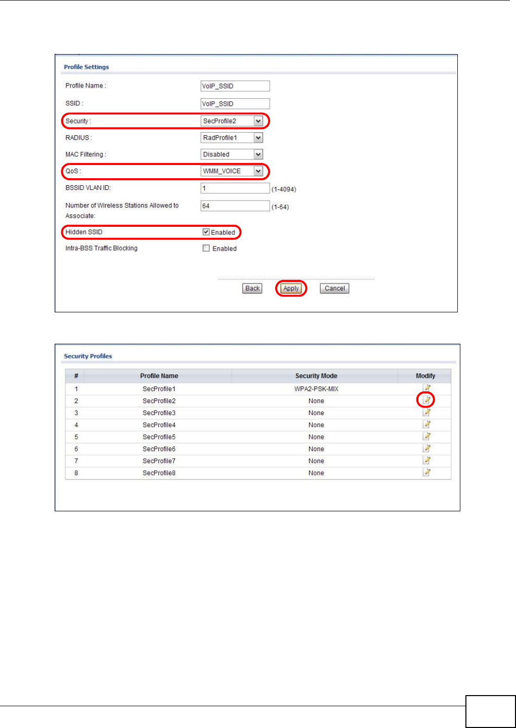
3Select WMM_VOICE in the QoS field to give VoIP the highest priority in the wireless network. Click
Apply.
4Next, click Wireless LAN > Security. Click the Edit icon next to SecProfile2.
Chapter 4 Tutorial
NWA1120 Series User’s Guide
36
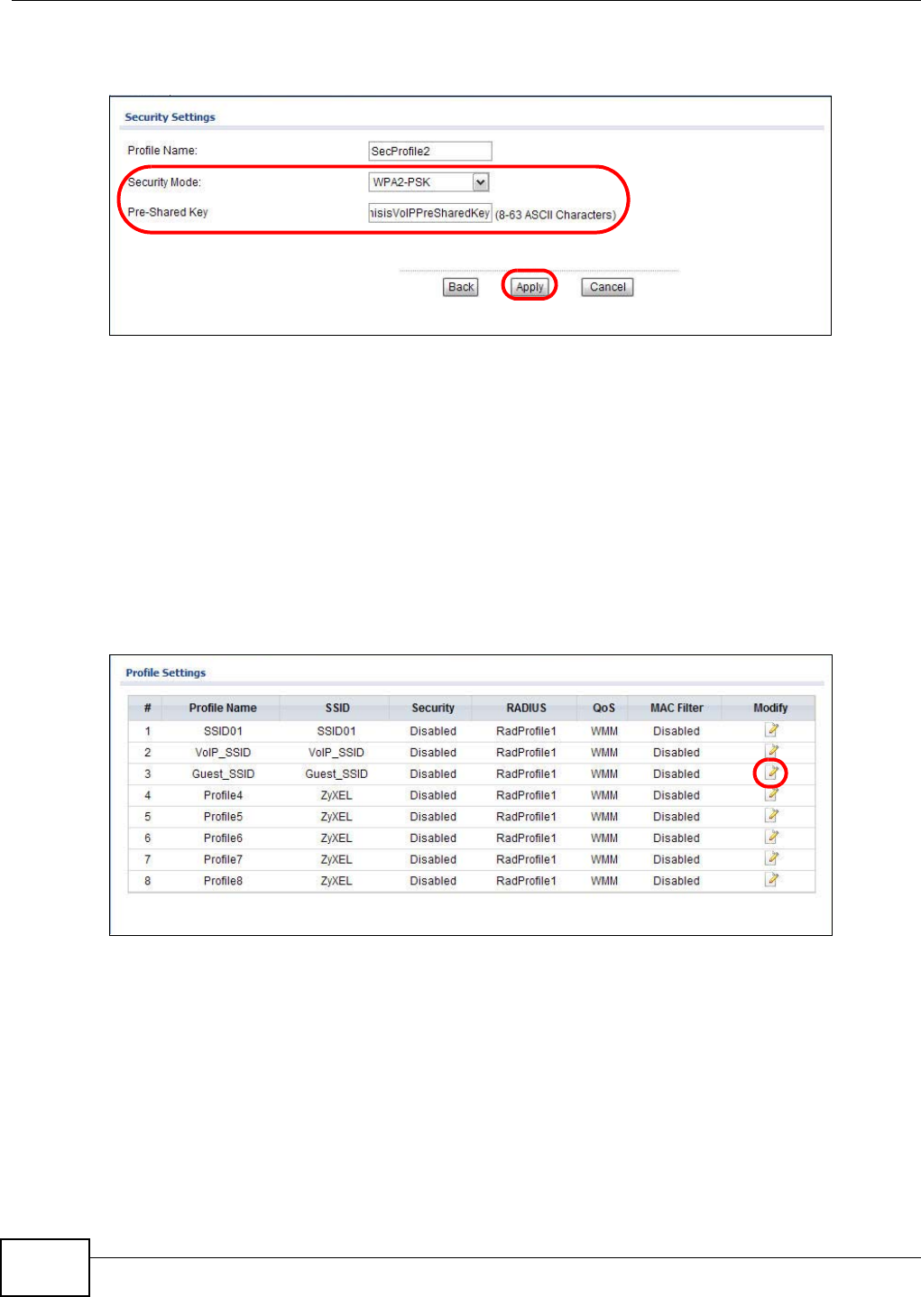
5Select WPA2-PSK as the Security Mode, and enter the Pre-Shared Key. In this example, use
ThisisVoIPPreSharedKey. Click Apply.
6Your VoIP wireless network is now ready to use. Any traffic using the VoIP_SSID profile will be
given the highest priority across the wireless network.
4.2.4 Configure the Guest Network
When you are setting up the wireless network for guests to your office, your primary concern is to
keep your network secure while allowing access to certain resources (such as a network printer, or
the Internet). For this reason, the pre-configured Guest_SSID profile has intra-BSS traffic blocking
enabled by default. “Intra-BSS traffic blocking” means that the client cannot access other clients on
the same wireless network.
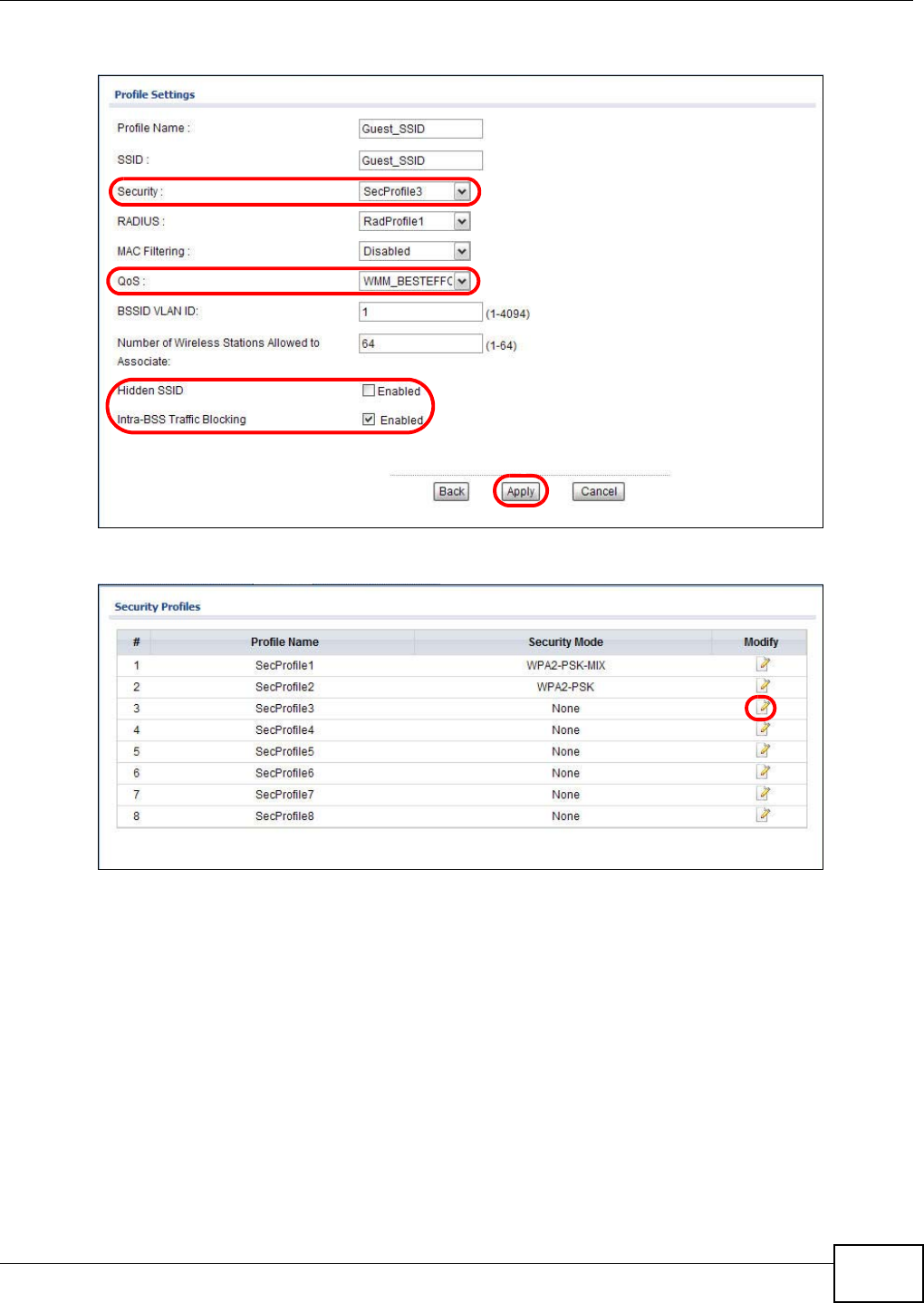
1Click Wireless LAN > SSID. Click the Edit icon next to Guest_SSID.
2Select SecProfile3 in the Security field. Do not select the Hidden SSID check-box so the guests
can easily find the wireless network.
3Select WMM_BESTEFFORT in the QoS field to give the guest a lower QoS priority.
Chapter 4 Tutorial
NWA1120 Series User’s Guide 37
4Select the check-box of Intra-BSS Traffic blocking Enabled. Click Apply.
5Next, click Wireless LAN > Security. Click the Edit icon next to SecProfile3.
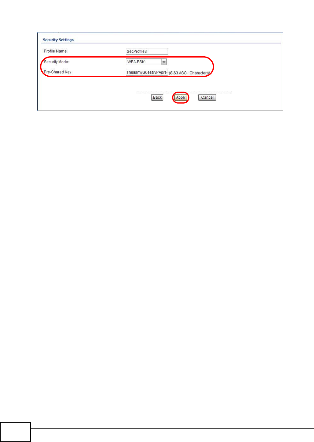
6Select WPA-PSK in the Security Mode field. WPA-PSK provides strong security that is supported
by most wireless clients. Even though your Guest_SSID clients do not have access to sensitive
information on the network, you should not leave the network without security. An attacker could
still cause damage to the network or intercept unsecured communications or use your Internet
access for illegal activities.
Chapter 4 Tutorial
NWA1120 Series User’s Guide
38
7Enter the PSK you want to use in your network in the Pre Shared Key field. In this example, the
PSK is ThisismyGuestWPApre-sharedkey. Click Apply.
8Your guest wireless network is now ready to use.
4.2.5 Testing the Wireless Networks
To make sure that the three networks are correctly configured, do the following.
• On a computer with a wireless client, scan for access points. You should see the Guest_SSID
network, but not the SSID01 and VoIP_SSID networks. If you can see the SSID01 and
VoIP_SSID networks, go to its SSID Edit screen and make sure to select the Hidden SSID
check-box and click Apply.
• Try to access each network using the correct security settings, and then using incorrect security
settings, such as the WPA-PSK for another active network. If the behavior is different from
expected (for example, if you can access the SSID01 or VoIP_SSID wireless network using the
security settings for the Guest_SSID wireless network) check that the SSID profile is set to use
the correct security profile, and that the settings of the security profile are correct.
4.3 NWA Setup in AP and Wireless Client Modes
This example shows you how to restrict wireless access to your NWA.
4.3.1 Scenario
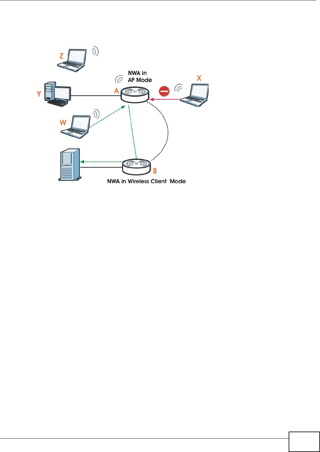
In the figure below, there are two NWAs (A and B) in the network. A is in MBSSID or root AP mode
while station B is in wireless client mode. Station B is connected to a File Transfer Protocol (FTP)
server. You want only specified wireless clients to be able to access station B. You also want to allow
Chapter 4 Tutorial
NWA1120 Series User’s Guide 39
wireless traffic between B and wireless clients connected to A (W, Y and Z). Other wireless devices
(X) must not be able to connect to the FTP server.
Figure 13 FTP Server Connected to a Wireless Client
4.3.2 Configuring the NWA in MBSSID or Root AP Mode
Before setting up the NWA as a wireless client (B), you need to make sure there is an access point
to connect to. Use the Ethernet port on NWA (A) to configure it via a wired connection.
Chapter 4 Tutorial
NWA1120 Series User’s Guide
40
Log into the Web Configurator on NWA (A) and go to the Wireless LAN > Wireless Settings
screen.
1Set the Operation Mode to Root AP.
2Select the Wireless Mode. In this example, select 802.11b/g/n.
3Select Profile1 as the SSID Profile.
4Choose the Channel you want NWA (A) to use.
5Click Apply.
Chapter 4 Tutorial
NWA1120 Series User’s Guide 41
6Go to Wireless LAN > SSID. Click the Edit icon next to Profile1.
7Change the SSID to AP-A.
8Select SecProfile1 in the Security field.
9Select the check-box for Intra-BSS Traffic blocking Enabled so the client cannot access other
clients on the same wireless network.
10 Click Apply.
Chapter 4 Tutorial
NWA1120 Series User’s Guide
42
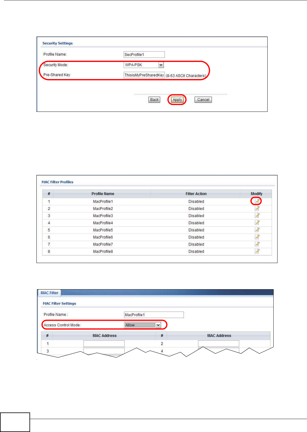
11 Go to Wireless LAN > Security. Click the Edit icon next to SecProfile1.
12 Configure WPA-PSK as the Security Mode and enter ThisisMyPreSharedKey in the Pre-
Shared Key field.
13 Click Apply to finish configuration for NWA (A).
4.3.3 Configuring the NWA in Wireless Client Mode
The NWA (B) should have a wired connection before it can be set to wireless client operating mode.
Connect your NWA to the FTP server. Login to NWA (B)’s Web Configurator and go to the Wireless
LAN > Wireless Settings screen. Follow these steps to configure station B.
Chapter 4 Tutorial
NWA1120 Series User’s Guide 43
1Select Client as Operation Mode. Click Apply.
2Click on the Site Survey button. A window should pop up which contains a list of all available
wireless devices within your NWA’s range.
3Find and select NWA (A)’s SSID: AP-A.
Chapter 4 Tutorial
NWA1120 Series User’s Guide
44
4Go to Wireless LAN > Security to configure the NWA to use the same security mode and Pre-
Shared Key as NWA (A): WPA-PSK/ThisisMyPreSharedKey. Click Apply.
Figure 14
4.3.4 MAC Filter Setup
One way to ensure that only specified wireless clients can access the FTP server is by enabling MAC
filtering on NWA (B) (See Section 6.9 on page 86 for more information on MAC Filter).
1Go to Wireless LAN > MAC Filter. Click the Edit icon next to MacProfile1.
2Select Allow in the Access Control Mode field. Enter the MAC addresses of the wireless clients
(W, Y and Z) you want to associate with the NWA. Click Apply.
Now, only the authorized wireless clients (W, Y and Z) can access the FTP server.

Chapter 4 Tutorial
NWA1120 Series User’s Guide 45
4.3.5 Testing the Connection and Troubleshooting
This section discusses how you can check if you have correctly configured your network setup as
described in this tutorial.
• Try accessing the FTP server from wireless clients W, Y or Z. Test if you can send or retrieve a
file. If you cannot establish a connection with the FTP server, do the following steps.
1Make sure W, Y and Z use the same wireless security settings as A and can access A.
2Make sure B uses the same wireless and wireless security settings as A and can access A.
3Make sure intra-BSS traffic is enabled on A.
• Try accessing the FTP server from X. If you are able to access the FTP server, do the following.
1Make sure MAC filtering is enabled.
2Make sure X’s MAC address is not entered in the list of allowed devices.

Chapter 4 Tutorial
NWA1120 Series User’s Guide
46

47
PART II
Technical Reference
The appendices provide general information. Some details may not apply to your NWA.

48

NWA1120 Series User’s Guide 49
CHAPTER 5
Monitor
5.1 Overview
This chapter discusses read-only information related to the device state of the NWA.
Note: To access the Monitor screens, you can also click the links in the Summary table of
the Dashboard screen to view the wireless packets sent/received as well as the
status of clients connected to the NWA.
5.2 What You Can Do
•Use the Logs screen to see the logs for the categories that you selected in the Configuration >
Log Settings screen (see Section 5.3 on page 49). You can view logs in this page. Once the log
entries are all used, the log will wrap around and the old logs will be deleted.
•use the Statistics screen to view 802.11 mode, channel number, wireless packet specific
statistics and so on (see Section 5.4 on page 50).
•Use the Association List screen to view the wireless devices that are currently associated to the
NWA (see Section 5.5 on page 51).
•Use the Channel Usage screen to view whether a channel is used by another wireless network
or not. If a channel is being used, you should select a channel removed from it by five channels
to completely avoid overlap (see Section 5.6 on page 52).
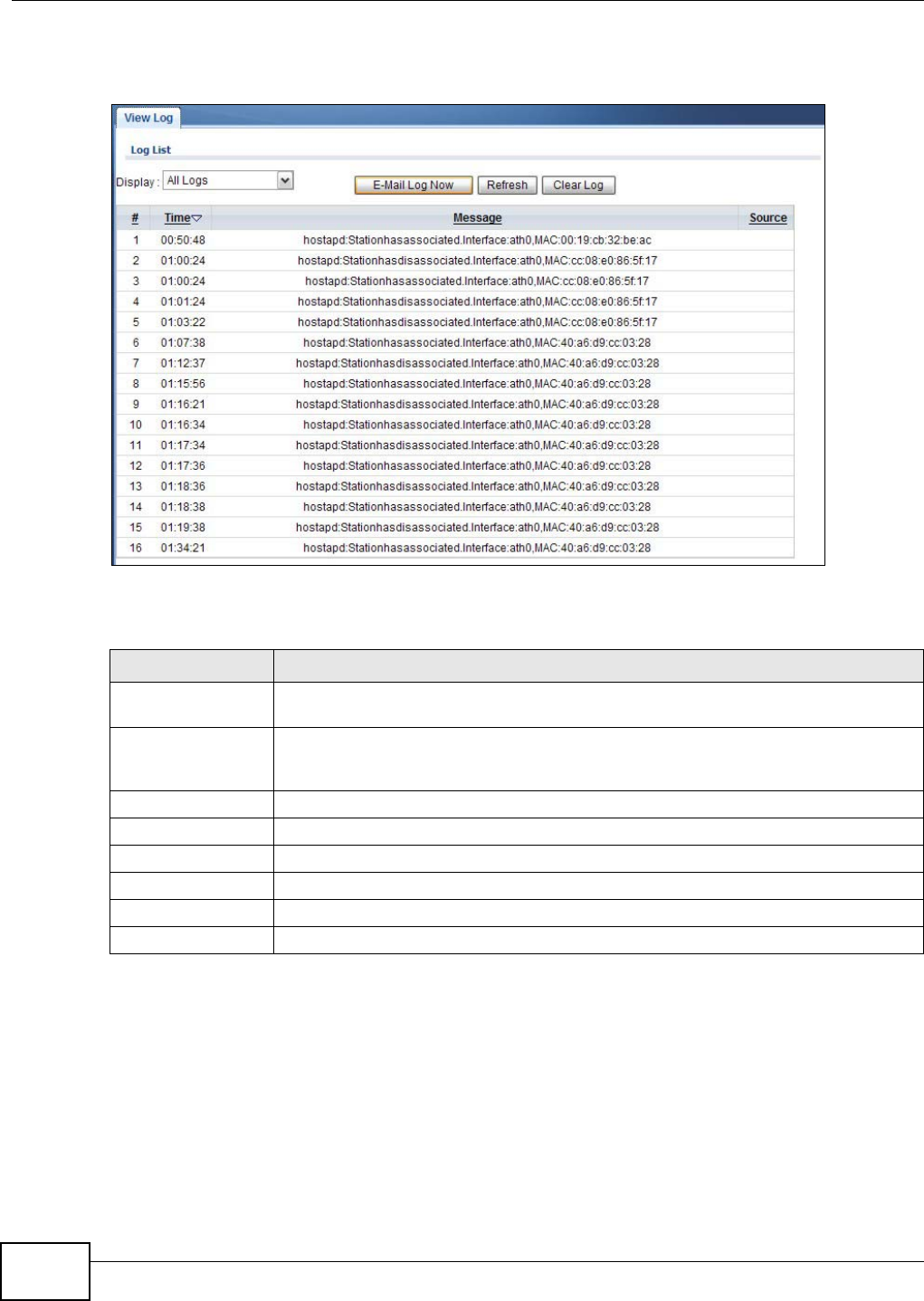
5.3 View Logs
Use the Logs screen to see the logged messages for the NWA.
Log entries in red indicate system error logs. The log wraps around and deletes the old entries after
it fills.
Chapter 5 Monitor
NWA1120 Series User’s Guide
50
Click Monitor > Logs.
Figure 15 Logs
The following table describes the labels in this screen.
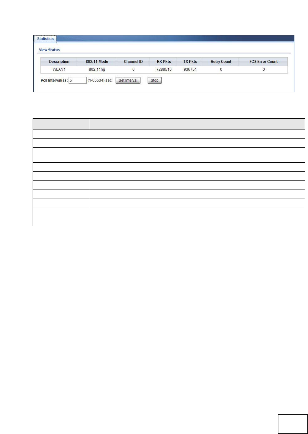
5.4 Statistics
Use this screen to view read-only information, including 802.11 Mode, Channel ID, Retry Count and
FCS Error Count. Also provided is the "poll interval". The Poll Interval field is configurable and is
used for refreshing the screen.
Table 6 Logs
LABEL DESCRIPTION
Display Select a category of logs to view. Select All Log to view logs from all of the log
categories that you selected in the Configuration > Log Settings screen.
E-Mail Log Now Click E-Mail Log Now to send the log screen to the e-mail address specified in the Log
Settings page (make sure that you have first filled in the E-mail Log Settings fields in
Configuration > Log Settings).
Refresh Click Refresh to renew the log screen.
Clear Log Click Clear Log to delete all the logs.
#This field is a sequential value and is not associated with a specific entry.
Time This field displays the time the log was recorded.
Message This field states the reason for the log.
Source This field lists the source IP address and the port number of the incoming packet.
Chapter 5 Monitor
NWA1120 Series User’s Guide 51
Click Monitor > Statistics. The following screen pops up.
Figure 16 Statistics
The following table describes the labels in this screen.
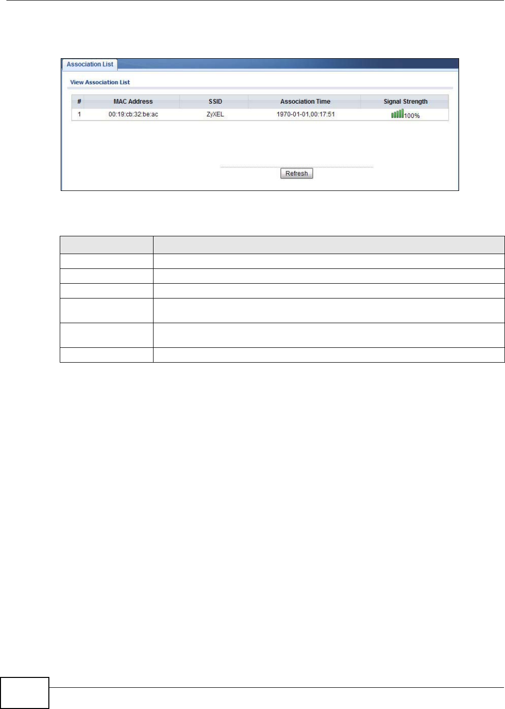
5.5 Association List
View the wireless devices that are currently associated with the NWA in the Association List
screen. Association means that a wireless client (for example, your network or computer with a
wireless network card) has connected successfully to the AP (or wireless router) using the same
SSID, channel and security settings.
Table 7 Statistics
LABEL DESCRIPTION
Description This is the wireless interface on the NWA.
802.11 Mode This field shows which 802.11 mode the NWA is using.
Channel ID This shows the channel number which the NWA is currently using over the wireless
LAN.
RX Pkts This is the number of received packets on this port.
TX Pkts This is the number of transmitted packets on this port.
Retry Count This is the total number of retries for transmitted packets (TX).
FCS Error Count This is the total number of checksum error of received packets (RX).
Poll Interval Enter the time interval for refreshing statistics.
Set Interval Click this button to apply the new poll interval you entered above.
Stop Click this button to stop refreshing statistics.
Chapter 5 Monitor
NWA1120 Series User’s Guide
52
Click Monitor > Association List to display the screen as shown next.
Figure 17 Association List
The following table describes the labels in this screen.
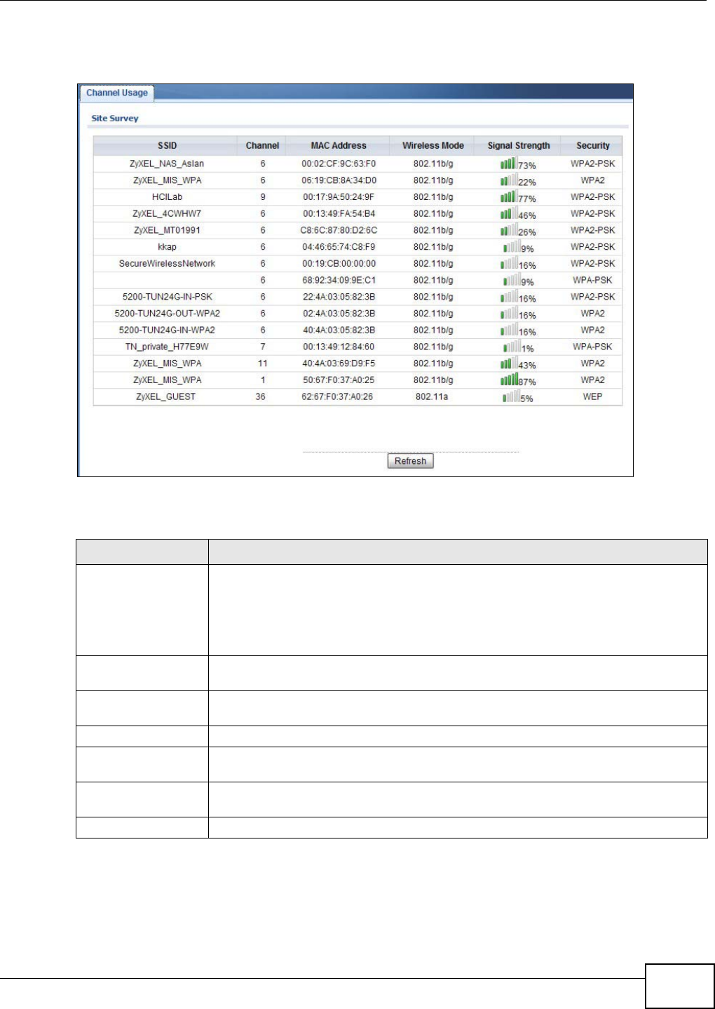
5.6 Channel Usage
Use this screen to know whether a channel is used by another wireless network or not. If a channel
is being used, you should select a channel removed from it by five channels to completely avoid
overlap.
Click Monitor > Channel Usage to display the screen shown next.
Table 8 Association List
LABEL DESCRIPTION
#This is the index number of an associated wireless device.
MAC Address This field displays the MAC address of an associated wireless device.
SSID This field displays the SSID to which the wireless device is associated.
Association Time This field displays the time a wireless device first associated with the NWA’s wireless
network.
Signal Strength This field displays the RSSI (Received Signal Strength Indicator) of the wireless
connection.
Refresh Click Refresh to reload the list.
Chapter 5 Monitor
NWA1120 Series User’s Guide 53
Wait a moment while the NWA compiles the information.
Figure 18 Channel Usage
The following table describes the labels in this screen.
Table 9 Channel Usage
LABEL DESCRIPTION
SSID This is the Service Set IDentification (SSID) name of the AP in an Infrastructure
wireless network or wireless station in an Ad-Hoc wireless network. For our purposes,
we define an Infrastructure network as a wireless network that uses an AP and an Ad-
Hoc network (also known as Independent Basic Service Set (IBSS)) as one that
doesn’t. See the chapter on wireless configuration for more information on basic
service sets (BSS) and extended service sets (ESS).
Channel This is the index number of the channel currently used by the associated AP in an
Infrastructure wireless network or wireless station in an Ad-Hoc wireless network.
MAC Address This field displays the MAC address of the AP in an Infrastructure wireless network. It
is randomly generated (so ignore it) in an Ad-Hoc wireless network.
Wireless Mode This is the IEEE 802.1x standard used by the wireless network.
Signal Strength This field displays the strength of the AP’s signal. If you must choose a channel that is
currently in use, choose one with low signal strength for minimum interference.
Security This is the wireless security method used by the wireless network to protect wireless
communication between wireless stations, access points and the wired network.
Refresh Click Refresh to reload the screen.

Chapter 5 Monitor
NWA1120 Series User’s Guide
54
NWA1120 Series User’s Guide 55
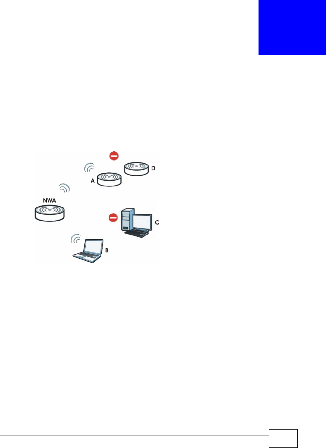
CHAPTER 6
Wireless LAN
6.1 Overview
This chapter discusses the steps to configure the Wireless Settings screen on the NWA. It also
introduces the wireless LAN (WLAN) and some basic scenarios.
Figure 19 Wireless Mode
In the figure above, the NWA allows access to another bridge device (A) and a notebook computer
(B) upon verifying their settings and credentials. It denies access to other devices (C and D) with
configurations that do not match those specified in your NWA.
6.2 What You Can Do in this Chapter
•Use the Wireless Settings screen to configure the NWA’s operation mode (see Section 6.4 on
page 60).
•Uee the SSID screen to configure up to eight SSID profiles for your NWA (see Section 6.5 on
page 74).
•Use the Security screen to choose the wireless security mode for your NWA (see Section 6.6 on
page 76).
•Use the RADIUS screen if you want to authenticate wireless users using a RADIUS Server and/or
accounting server (see Section 6.7 on page 82).
•Use the Layer-2 Isolation screen to configure the MAC addresses of the devices that you want
to allow the associated wireless clients to have access to when layer-2 isolation is enabled. (see
Section 6.8 on page 84).

Chapter 6 Wireless LAN
NWA1120 Series User’s Guide
56
•Use the MAC Filter screen to specify which wireless station is allowed or denied access to the
NWA (see Section 6.9 on page 86).
6.3 What You Need To Know
BSS
A Basic Service Set (BSS) exists when all communications between wireless clients or between a
wireless client and a wired network client go through one access point (AP). Intra-BSS traffic is
traffic between wireless clients in the BSS.
ESS
An Extended Service Set (ESS) consists of a series of overlapping BSSs, each containing an access
point, with each access point connected together by a wired network. This wired connection
between APs is called a Distribution System (DS).
Operating Mode
The NWA can run in four operating modes as follows:
•Root AP. The NWA is a wireless access point that allows wireless communication to other
devices in the network.
•Repeater. The NWA acts as a wireless repeater and increase a root AP’s wireless coverage
area.
•Client. The NWA acts as a wireless client to access a wireless network.
•MBSSID. The Multiple Basic Service Set Identifier (MBSSID) mode allows you to use one
access point to provide several BSSs simultaneously.
Refer to Chapter 1 on page 11 for illustrations of these wireless applications.
SSID
The SSID (Service Set IDentifier) is the name that identifies the Service Set with which a wireless
station is associated. Wireless stations associating to the access point (AP) must have the same
SSID. In other words, it is the name of the wireless network that clients use to connect to it.
Normally, the NWA acts like a beacon and regularly broadcasts the SSID in the area. You can hide
the SSID instead, in which case the NWA does not broadcast the SSID. In addition, you should
change the default SSID to something that is difficult to guess.
This type of security is fairly weak, however, because there are ways for unauthorized wireless
devices to get the SSID. In addition, unauthorized wireless devices can still see the information that
is sent in the wireless network.
Chapter 6 Wireless LAN
NWA1120 Series User’s Guide 57
Channel
A channel is the radio frequency(ies) used by wireless devices. Channels available depend on your
geographical area. You may have a choice of channels (for your region) so you should use a
different channel than an adjacent AP (access point) to reduce interference.
Wireless Mode
The IEEE 802.1x standard was designed to extend the features of IEEE 802.11 to support extended
authentication as well as providing additional accounting and control features.
MBSSID
Traditionally, you needed to use different APs to configure different Basic Service Sets (BSSs). As
well as the cost of buying extra APs, there was also the possibility of channel interference. The
NWA’s MBSSID (Multiple Basic Service Set IDentifier) function allows you to use one access point to
provide several BSSs simultaneously. You can then assign varying levels of privilege to different
SSIDs.
Wireless stations can use different BSSIDs to associate with the same AP.
The following are some notes on multiple BSS.
• A maximum of four BSSs are allowed on one AP simultaneously.
• You must use different WEP keys for different BSSs. If two stations have different BSSIDs (they
are in different BSSs), but have the same WEP keys, they may hear each other’s communications
(but not communicate with each other).
• MBSSID should not replace but rather be used in conjunction with 802.1x security.
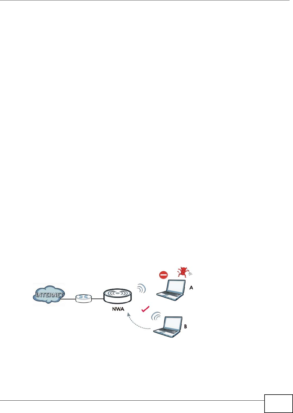
Wireless Security
Wireless security is vital to your network. It protects communications between wireless stations,
access points and the wired network.
Figure 20 Securing the Wireless Network
In the figure above, the NWA checks the identity of devices before giving them access to the
network. In this scenario, Computer A is denied access to the network, while Computer B is
granted connectivity.

Chapter 6 Wireless LAN
NWA1120 Series User’s Guide
58
The NWA secure communications via data encryption, wireless client authentication and MAC
address filtering. It can also hide its identity in the network.
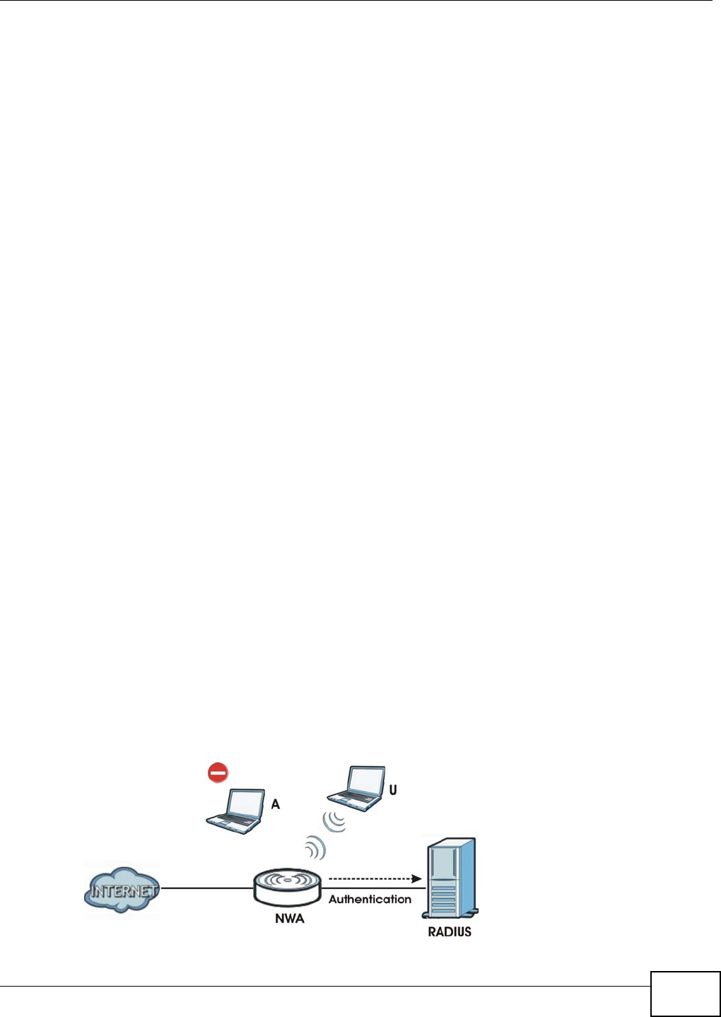
User Authentication
Authentication is the process of verifying whether a wireless device is allowed to use the wireless
network. You can make every user log in to the wireless network before they can use it. However,
every device in the wireless network has to support IEEE 802.1x to do this.
For wireless networks, you can store the user names and passwords for each user in a RADIUS
server. This is a server used in businesses more than in homes. If you do not have a RADIUS server,
you cannot set up user names and passwords for your users.
Unauthorized wireless devices can still see the information that is sent in the wireless network,
even if they cannot use the wireless network. Furthermore, there are ways for unauthorized
wireless users to get a valid user name and password. Then, they can use that user name and
password to use the wireless network.
The following table shows the relative effectiveness of wireless security methods:.
The available security modes in your NWA are as follows:
•None. No data encryption.
•WEP. Wired Equivalent Privacy (WEP) encryption scrambles the data transmitted between the
wireless stations and the access points to keep network communications private.
•WPA. Wi-Fi Protected Access (WPA) is a subset of the IEEE 802.11i standard.
•WPA2. WPA2 (IEEE 802.11i) is a wireless security standard that defines stronger encryption,
authentication and key management than WPA.
•WPA2-MIX. This commands the NWA to use either WPA2 or WPA depending on which security
mode the wireless client uses.
•WPA-PSK. This adds a pre-shared key on top of WPA standard.
•WPA2-PSK. This adds a pre-shared key on top of WPA2 standard.
•WPA2-PSK-MIX. This commands the NWA to use either WPA-PSK or WPA2-PSK depending on
which security mode the wireless client uses.
Note: To guarantee 802.11n wireless speed, please only use WPA2 or WPA2-PSK security
mode. Other security modes may degrate the wireless speed performance to
802.11g.
Table 10 Wireless Security Levels
SECURITY
LEVEL SECURITY TYPE
Least
Secure
Most Secure
Unique SSID (Default)
Unique SSID with Hide SSID Enabled
MAC Address Filtering
WEP Encryption
IEEE802.1x EAP with RADIUS Server Authentication
Wi-Fi Protected Access (WPA)
WPA2
Chapter 6 Wireless LAN
NWA1120 Series User’s Guide 59
Passphrase
A passphrase functions like a password. In WEP security mode, it is further converted by the NWA
into a complicated string that is referred to as the “key”. This key is requested from all devices
wishing to connect to a wireless network.
PSK
The Pre-Shared Key (PSK) is a password shared by a wireless access point and a client during a
previous secure connection. The key can then be used to establish a connection between the two
parties.
Encryption
Wireless networks can use encryption to protect the information that is sent in the wireless
network. Encryption is like a secret code. If you do not know the secret code, you cannot
understand the message. Encryption is the process of converting data into unreadable text. This
secures information in network communications. The intended recipient of the data can “unlock” it
with a pre-assigned key, making the information readable only to him. The NWA when used as a
wireless client employs Temporal Key Integrity Protocol (TKIP) data encryption.
EAP
Extensible Authentication Protocol (EAP) is a protocol used by a wireless client, an access point and
an authentication server to negotiate a connection.
The EAP methods employed by the NWA when in Wireless Client operating mode are Transport
Layer Security (TLS), Protected Extensible Authentication Protocol (PEAP), Lightweight Extensible
Authentication Protocol (LEAP) and Tunneled Transport Layer Security (TTLS). The authentication
protocol may either be Microsoft Challenge Handshake Authentication Protocol Version 2
(MSCHAPv2) or Generic Token Card (GTC).
Further information on these terms can be found in Appendix E on page 187.
RADIUS
Remote Authentication Dial In User Service (RADIUS) is a protocol that can be used to manage user
access to large networks. It is based on a client-server model that supports authentication,
authorization and accounting. The access point is the client and the server is the RADIUS server.
Figure 21 RADIUS Server Setup

Chapter 6 Wireless LAN
NWA1120 Series User’s Guide
60
In the figure above, wireless clients A and B are trying to access the Internet via the NWA. The
NWA in turn queries the RADIUS server if the identity of clients A and U are allowed access to the
Internet. In this scenario, only client U’s identity is verified by the RADIUS server and allowed
access to the Internet.
The RADIUS server handles the following tasks:
•Authentication which determines the identity of the users.
•Authorization which determines the network services available to authenticated users once
they are connected to the network.
•Accounting which keeps track of the client’s network activity.
RADIUS is a simple package exchange in which your AP acts as a message relay between the
wireless client and the network RADIUS server.
You should know the IP addresses, ports and share secrets of the external RADIUS server and/or
the external RADIUS accounting server you want to use with your NWA. You can configure a
primary and backup RADIUS and RADIUS accounting server for your NWA.
6.4 Wireless Settings Screen
Use this screen to choose the operating mode for your NWA. Click Network > Wireless LAN >
Wireless Settings, Network > Wireless LAN > Wireless Settings- 2.4G or Network >
Wireless LAN > Wireless Settings - 5G. The screen varies depending upon the operating mode
you select.
Chapter 6 Wireless LAN
NWA1120 Series User’s Guide 61
6.4.1 Root AP Mode
Use this screen to use your NWA as an access point. Select Root AP as the Operation Mode. The
following screen displays.
Figure 22 Wireless LAN > Wireless Settings: Root AP

Chapter 6 Wireless LAN
NWA1120 Series User’s Guide
62
The following table describes the general wireless LAN labels in this screen.
Table 11 Wireless LAN > Wireless Settings: Root AP
LABEL DESCRIPTION
Basic Settings
Wireless LAN
Interface Select the check box to turn on the wireless LAN on the NWA.
Operation Mode Select Root AP from the drop-down list.
Wireless Mode If you are in the Wireless LAN > Wireless Settings or Wireless LAN > Wireless
Settings- 2.4G screen, you can select from the following:
•802.11b/g to allow both IEEE802.11b and IEEE802.11g compliant WLAN devices to
associate with the NWA. The transmission rate of your NWA might be reduced.
•802.11b/g/n to allow IEEE802.11b, IEEE802.11g and IEEE802.11n compliant WLAN
devices to associate with the NWA. The transmission rate of the NWA might be
reduced.
•802.11n to allow only IEEE802.11n compliant WLAN devices to associate with the
NWA.
If you are in the Wireless LAN > Wireless Settings- 5G screen, you can select from
the following:
•802.11a/n to allow IEEE802.11a and IEEE802.11n compliant WLAN devices to
associate with the NWA.
•802.11a to allow only IEEE802.11a compliant WLAN devices to associate with the
NWA.
•802.11n to allow only IEEE802.11n compliant WLAN devices to associate with the
NWA.
•802.11a/n/ac to allow IEEE802.11a, IEEE802.11n and IEEE802.11ac compliant
WLAN devices to associate with the NWA. The transmission rate of the NWA might be
reduced.
Channel Select the operating frequency/channel depending on your particular region from the
drop-down list box.
Channel Width This field displays only when you select 802.11n, 802.11a/n, 802.11b/g/n or
802.11a/n/ac in the Wireless Mode field.
A standard 20MHz channel offers transfer speeds of up to 150Mbps whereas a 40MHz
channel uses two standard channels and offers speeds of up to 300Mbps. However, not all
devices support 40MHz channels.
Select the channel bandwidth you want to use for your wireless network.
It is recommended that you select 20/40MHz. This allows the NWA to adjust the channel
bandwidth depending on network conditions.
Select 20MHz if you want to lessen radio interference with other wireless devices in your
neighborhood or the wireless clients do not support channel bonding.
Select SSID
Profile The SSID (Service Set IDentifier) identifies the Service Set with which a wireless station is
associated. Wireless stations associating to the access point (AP) must have the same
SSID. You can have up to four SSIDs active at the same time.
Note: If you are configuring the NWA from a computer connected to the wireless LAN and
you change the NWA’s SSID or security settings, you will lose your wireless
connection when you press Apply to confirm. You must then change the wireless
settings of your computer to match the NWA’s new settings.
#This is the index number of each SSID profile.
Activve Select the check box to enable an SSID profile. Otherwise, clear the check box.
Profile Select an SSID Profile from the drop-down list box.

Chapter 6 Wireless LAN
NWA1120 Series User’s Guide 63
Universal Repeater Settings
The Universal repeater function allows the NWA in root AP or repeater mode to set up a wireless connection
between it and another NWA in root AP or repeater mode.
Note: Universal repeater security is independent of the security settings between the NWA and any wireless
clients.
Local MAC
Address Local MAC Address is the MAC address of your NWA.
Universal
Repeater SSID
Profile
Select the SSID profile you want to use for universal repeater connections.
Note: You can only configure None, WPA-PSK or WPA2-PSK security mode for the SSID
used by a universal repeater connection.
Advanced Settings
Beacon Interval When a wirelessly network device sends a beacon, it includes with it a beacon interval.
This specifies the time period before the device sends the beacon again. The interval tells
receiving devices on the network how long they can wait in lowpower mode before waking
up to handle the beacon. A high value helps save current consumption of the access point.
DTIM Interval Delivery Traffic Indication Message (DTIM) is the time period after which broadcast and
multicast packets are transmitted to mobile clients in the Active Power Management
mode. A high DTIM value can cause clients to lose connectivity with the network.
Output Power Set the output power of the NWA in this field. If there is a high density of APs in an area,
decrease the output power of the NWA to reduce interference with other APs. Select one
of the following Full (Full Power), 50%, 25%, or 12.5%. See the product specifications
for more information on your NWA’s output power.
Preamble Type Select Dynamic to have the AP automatically use short preamble when wireless adapters
support it, otherwise the AP uses long preamble.
Select Long if you are unsure what preamble mode the wireless adapters support, and to
provide more reliable communications in busy wireless networks.
RTS/CTS
Threshold (Request To Send) The threshold (number of bytes) for enabling RTS/CTS handshake.
Data with its frame size larger than this value will perform the RTS/CTS handshake.
Setting this attribute to be larger than the maximum MSDU (MAC service data unit) size
turns off the RTS/CTS handshake. Setting this attribute to its smallest value (1) turns on
the RTS/CTS handshake.
Fragmentation The threshold (number of bytes) for the fragmentation boundary for directed messages. It
is the maximum data fragment size that can be sent.
Extension
Channel
Protection Mode
You can use CTS to self or RTS-CTS protection mechanism to reduce conflicts with other
wireless networks or hidden wireless clients. The throughput of RTS-CTS is much lower
than CTS to self. Using this mode may decrease your wireless performance.
A-MPDU
Aggregation This field is available only when 802.11n, 802.11b/g/n, 802.11a/n or 802.11a/n/ac
is selected as the Wireless Mode.
Select to enable A-MPDU aggregation.
Message Protocol Data Unit (MPDU) aggregation collects Ethernet frames along with their
802.11n headers and wraps them in a 802.11n MAC header. This method is useful for
increasing bandwidth throughput in environments that are prone to high error rates.
Short GI This field is available only when 802.11n, 802.11b/g/n, 802.11a/n or 802.11a/n/ac
is selected as the Wireless Mode.
Select Enabled to use Short GI (Guard Interval). The guard interval is the gap
introduced between data transmission from users in order to reduce interference.
Reducing the GI increases data transfer rates but also increases interference. Increasing
the GI reduces data transfer rates but also reduces interference.
Table 11 Wireless LAN > Wireless Settings: Root AP (continued)
LABEL DESCRIPTION

Chapter 6 Wireless LAN
NWA1120 Series User’s Guide
64
MCS Rate The MCS Rate table is available only when 802.11n, 802.11b/g/n, 802.11a/n or
802.11a/n/ac is selected in the Wireless Mode field.
IEEE 802.11n supports many different data rates which are called MCS rates. MCS stands
for Modulation and Coding Scheme. This is an 802.11n feature that increases the wireless
network performance in terms of throughput.
For each MCS Rate (0-15), select either Enabled to have the NWA use the data rate.
Clear the Enabled check box if you do not want the NWA to use the data rate.
Turn on the Auto option to have the NWA set the data rates automatically to optimize the
throughput.
Note: You can set the NWA to use up to four MCS rates at a time.
Apply Click Apply to save your changes.
Cancel Click Cancel to begin configuring this screen afresh.
Table 11 Wireless LAN > Wireless Settings: Root AP (continued)
LABEL DESCRIPTION
Chapter 6 Wireless LAN
NWA1120 Series User’s Guide 65
6.4.2 Repeater Mode
Use this screen to have the NWA act as a wireless repeater. You need to know the MAC address of
the peer device, which also must be in Repeater or Root AP mode.
Figure 23 Wireless LAN > Wireless Settings: Repeater
The following table describes the bridge labels in this screen.
Table 12 Wireless LAN > Wireless Settings: Repeater
LABEL DESCRIPTION
Basic Settings
Wireless LAN
Interface Select the check box to turn on the wireless LAN on the NWA.
Operation Mode Select Repeater from the drop-down list.

Chapter 6 Wireless LAN
NWA1120 Series User’s Guide
66
Wireless Mode If you are in the Wireless LAN > Wireless Settings or Wireless LAN > Wireless
Settings- 2.4G screen, you can select from the following:
•802.11b/g to allow both IEEE802.11b and IEEE802.11g compliant WLAN devices to
associate with the NWA. The transmission rate of your NWA might be reduced.
•802.11b/g/n to allow IEEE802.11b, IEEE802.11g and IEEE802.11n compliant WLAN
devices to associate with the NWA. The transmission rate of the NWA might be
reduced.
•802.11n to allow only IEEE802.11n compliant WLAN devices to associate with the
NWA.
If you are in the Wireless LAN > Wireless Settings- 5G screen, you can select from
the following:
•802.11a/n to allow IEEE802.11a and IEEE802.11n compliant WLAN devices to
associate with the NWA.
•802.11a to allow only IEEE802.11a compliant WLAN devices to associate with the
NWA.
•802.11n to allow only IEEE802.11n compliant WLAN devices to associate with the
NWA.
•802.11a/n/ac to allow IEEE802.11a, IEEE802.11n and IEEE802.11ac compliant
WLAN devices to associate with the NWA. The transmission rate of the NWA might be
reduced.
Channel Select the operating frequency/channel depending on your particular region from the
drop-down list box.
Channel Width This field displays only when you select 802.11n, 802.11a/n, 802.11b/g/n or
802.11a/n/ac in the Wireless Mode field.
A standard 20MHz channel offers transfer speeds of up to 150Mbps whereas a 40MHz
channel uses two standard channels and offers speeds of up to 300Mbps. However, not all
devices support 40MHz channels.
Select the channel bandwidth you want to use for your wireless network.
It is recommended that you select 20/40MHz. This allows the NWA to adjust the channel
bandwidth depending on network conditions.
Select 20MHz if you want to lessen radio interference with other wireless devices in your
neighborhood or the wireless clients do not support channel bonding.
Universal Repeater Settings
The Universal repeater function allows the NWA in root AP or repeater mode to set up a wireless connection
between it and another NWA in root AP or repeater mode.
Note: Universal repeater security is independent of the security settings between the NWA and any wireless
clients.
Local MAC
Address Local MAC Address is the MAC address of your NWA.
Universal
Repeater SSID
Profile
Select the SSID profile you want to use for universal repeater connections with an AP or
repeater or regular wireless connections with wireless clients.
Note: You can only configure None, WPA-PSK or WPA2-PSK security mode for the SSID
used by a universal repeater connection.
Root MAC
Address Specify the peer device’s MAC address. The peer device can be a NWA in either root AP
mode or repeater mode.
Advanced Settings
Beacon Interval When a wirelessly network device sends a beacon, it includes with it a beacon interval.
This specifies the time period before the device sends the beacon again. The interval tells
receiving devices on the network how long they can wait in lowpower mode before waking
up to handle the beacon. A high value helps save current consumption of the access point.
Table 12 Wireless LAN > Wireless Settings: Repeater (continued)
LABEL DESCRIPTION

Chapter 6 Wireless LAN
NWA1120 Series User’s Guide 67
DTIM Interval Delivery Traffic Indication Message (DTIM) is the time period after which broadcast and
multicast packets are transmitted to mobile clients in the Active Power Management
mode. A high DTIM value can cause clients to lose connectivity with the network.
Output Power Set the output power of the NWA in this field. If there is a high density of APs in an area,
decrease the output power of the NWA to reduce interference with other APs. Select one
of the following Full (Full Power), 50%, 25% or 12.5%. See the product specifications
for more information on your NWA’s output power.
Preamble Type Select Dynamic to have the AP automatically use short preamble when wireless adapters
support it, otherwise the AP uses long preamble.
Select Long if you are unsure what preamble mode the wireless adapters support, and to
provide more reliable communications in busy wireless networks.
RTS/CTS
Threshold (Request To Send) The threshold (number of bytes) for enabling RTS/CTS handshake.
Data with its frame size larger than this value will perform the RTS/CTS handshake.
Setting this attribute to be larger than the maximum MSDU (MAC service data unit) size
turns off the RTS/CTS handshake. Setting this attribute to its smallest value (1) turns on
the RTS/CTS handshake.
Fragmentation The threshold (number of bytes) for the fragmentation boundary for directed messages. It
is the maximum data fragment size that can be sent.
Extension
Channel
Protection Mode
You can use CTS to self or RTS-CTS protection mechanism to reduce conflicts with other
wireless networks or hidden wireless clients. The throughput of RTS-CTS is much lower
than CTS to self. Using this mode may decrease your wireless performance.
A-MPDU
Aggregation This field is available only when 802.11n, 802.11b/g/n, 802.11a/n or 802.11a/n/ac
is selected as the Wireless Mode.
Select to enable A-MPDU aggregation.
Message Protocol Data Unit (MPDU) aggregation collects Ethernet frames along with their
802.11n headers and wraps them in a 802.11n MAC header. This method is useful for
increasing bandwidth throughput in environments that are prone to high error rates.
Short GI This field is available only when 802.11n, 802.11b/g/n, 802.11a/n or 802.11a/n/ac
is selected as the Wireless Mode.
Select Enabled to use Short GI (Guard Interval). The guard interval is the gap
introduced between data transmission from users in order to reduce interference.
Reducing the GI increases data transfer rates but also increases interference. Increasing
the GI reduces data transfer rates but also reduces interference.
MCS Rate The MCS Rate table is available only when 802.11n, 802.11b/g/n, 802.11a/n or
802.11a/n/ac is selected in the Wireless Mode field.
IEEE 802.11n supports many different data rates which are called MCS rates. MCS stands
for Modulation and Coding Scheme. This is an 802.11n feature that increases the wireless
network performance in terms of throughput.
For each MCS Rate (0-15), select either Enabled to have the NWA use the data rate.
Clear the Enabled check box if you do not want the NWA to use the data rate.
Turn on the Auto option to have the NWA set the data rates automatically to optimize the
throughput.
Note: You can set the NWA to use up to four MCS rates at a time.
Apply Click Apply to save your changes.
Cancel Click Cancel to begin configuring this screen afresh.
Table 12 Wireless LAN > Wireless Settings: Repeater (continued)
LABEL DESCRIPTION
Chapter 6 Wireless LAN
NWA1120 Series User’s Guide
68
6.4.3 Wireless Client Mode
Use this screen to turn your NWA into a wireless client. Select Client as the Operation Mode. The
following screen displays.
Figure 24 Wireless LAN > Wireless Settings: Wireless Client
The following table describes the general wireless LAN labels in this screen.
Table 13 Wireless LAN > Wireless Settings: Wireless Client
LABEL DESCRIPTION
Basic Settings
Wireless LAN
Interface Select the check box to turn on the wireless LAN on the NWA.
Operation Mode Select Client in this field.
Site Survey Click this to view a list of available wireless access points within the range. Select the AP
you want to use.
Note: After selecting Client as the Operation Mode in the Basic Settings section, you must
click Apply to be able to select from the AP list.

Chapter 6 Wireless LAN
NWA1120 Series User’s Guide 69
SSID Profile The SSID (Service Set IDentifier) identifies the Service Set with which a wireless station is
associated. Wireless stations associating to the access point (AP) must have the same
SSID.
In this field, select the SSID profile of the AP you want to use. Click Apply.
The SSID used in the selected SSID profile automatically changes to be the one you select
in the Site Survey screen.
Set the security configuration for this operating mode in the Wireless LAN > Security
screen. Check the Dashboard screen to check if the settings you set show in the WLAN
information.
Note: If you are configuring the NWA from a computer connected to the wireless LAN and you
change the NWA’s SSID or security settings, you will lose your wireless connection
when you press Apply to confirm. You must then change the wireless settings of your
computer to match the NWA’s new settings.
Channel This shows the operating frequency/channel in use. This field is read-only when you select
Client as your operation mode.
Channel Width This field is not available in the NWA1123-NI.
A standard 20MHz channel offers transfer speeds of up to 150Mbps whereas a 40MHz
channel uses two standard channels and offers speeds of up to 300Mbps. However, not all
devices support 40MHz channels.
Select the channel bandwidth you want to use for your wireless network.
It is recommended that you select 20/40MHz. This allows the NWA to adjust the channel
bandwidth depending on network conditions.
Select 20MHz if you want to lessen radio interference with other wireless devices in your
neighborhood or the AP do not support channel bonding.
Advanced Settings
Output Power Set the output power of the NWA in this field. If there is a high density of APs in an area,
decrease the output power of the NWA to reduce interference with other APs. Select one of
the following Full (Full Power), 50%, 25% or 12.5%. See the product specifications for
more information on your NWA’s output power.
Preamble Type Select Dynamic to have the NWA automatically use short preamble when the wireless
network your NWA is connected to supports it, otherwise the NWA uses long preamble.
Select Long preamble if you are unsure what preamble mode the wireless device your NWA
is connected to supports, and to provide more reliable communications in busy wireless
networks.
RTS/CTS
Threshold (Request To Send) The threshold (number of bytes) for enabling RTS/CTS handshake. Data
with its frame size larger than this value will perform the RTS/CTS handshake. Setting this
attribute to be larger than the maximum MSDU (MAC service data unit) size turns off the
RTS/CTS handshake. Setting this attribute to its smallest value (1) turns on the RTS/CTS
handshake.
Fragmentation This field is not available in the NWA1123-NI.
The threshold (number of bytes) for the fragmentation boundary for directed messages. It
is the maximum data fragment size that can be sent.
Extension
channel
protection mode
You can use CTS to self or RTS-CTS protection mechanism to reduce conflicts with other
wireless networks or hidden wireless clients. The throughput of RTS-CTS is much lower
than CTS to self. Using this mode may decrease your wireless performance.
Table 13 Wireless LAN > Wireless Settings: Wireless Client (continued)
LABEL DESCRIPTION

Chapter 6 Wireless LAN
NWA1120 Series User’s Guide
70
A-MPDU
Aggregation This field is not available in the NWA1123-NI.
Select to enable A-MPDU aggregation.
Message Protocol Data Unit (MPDU) aggregation collects Ethernet frames along with their
802.11n headers and wraps them in a 802.11n MAC header. This method is useful for
increasing bandwidth throughput in environments that are prone to high error rates.
Short GI This field is not available in the NWA1123-NI.
Select Enabled to use Short GI (Guard Interval). The guard interval is the gap introduced
between data transmission from users in order to reduce interference. Reducing the GI
increases data transfer rates but also increases interference. Increasing the GI reduces data
transfer rates but also reduces interference.
Apply Click Apply to save your changes.
Cancel Click Cancel to begin configuring this screen afresh.
Table 13 Wireless LAN > Wireless Settings: Wireless Client (continued)
LABEL DESCRIPTION
Chapter 6 Wireless LAN
NWA1120 Series User’s Guide 71
6.4.4 MBSSID Mode
Use this screen to have the NWA function in MBSSID mode. Select MBSSID as the Operation
Mode. The following screen diplays.
Figure 25 Wireless LAN > Wireless Settings: MBSSID
The following table describes the labels in this screen.
Table 14 Wireless LAN > Wireless Settings: MBSSID
LABEL DESCRIPTION
Basic Settings
Wireless LAN
Interface Select the check box to turn on the wireless LAN on the NWA.
Operation Mode Select MBSSID from the drop-down list.

Chapter 6 Wireless LAN
NWA1120 Series User’s Guide
72
Wireless Mode If you are in the Wireless LAN > Wireless Settings or Wireless LAN > Wireless
Settings- 2.4G screen, you can select from the following:
•802.11b/g to allow both IEEE802.11b and IEEE802.11g compliant WLAN devices to
associate with the NWA. The transmission rate of your NWA might be reduced.
•802.11b/g/n to allow IEEE802.11b, IEEE802.11g and IEEE802.11n compliant WLAN
devices to associate with the NWA. The transmission rate of the NWA might be
reduced.
•802.11n to allow only IEEE802.11n compliant WLAN devices to associate with the
NWA.
If you are in the Wireless LAN > Wireless Settings- 5G screen, you can select from
the following:
•802.11a/n to allow IEEE802.11a and IEEE802.11n compliant WLAN devices to
associate with the NWA.
•802.11a to allow only IEEE802.11a compliant WLAN devices to associate with the
NWA.
•802.11n to allow only IEEE802.11n compliant WLAN devices to associate with the
NWA.
•802.11a/n/ac to allow IEEE802.11a, IEEE802.11n and IEEE802.11ac compliant
WLAN devices to associate with the NWA. The transmission rate of the NWA might be
reduced.
Channel Select the operating frequency/channel depending on your particular region from the
drop-down list box.
Channel Width This field displays only when you select 802.11n, 802.11a/n, 802.11b/g/n or
802.11a/n/ac in the Wireless Mode field.
A standard 20MHz channel offers transfer speeds of up to 150Mbps whereas a 40MHz
channel uses two standard channels and offers speeds of up to 300Mbps. However, not all
devices support 40MHz channels.
Select the channel bandwidth you want to use for your wireless network.
Select 20MHz if you want to lessen radio interference with other wireless devices in your
neighborhood or the wireless clients do not support channel bonding.
Select SSID
Profile The SSID (Service Set IDentifier) identifies the Service Set with which a wireless station is
associated. Wireless stations associating to the access point (AP) must have the same
SSID. You can have up to eight SSIDs active at the same time.
Note: If you are configuring the NWA from a computer connected to the wireless LAN and
you change the NWA’s SSID or security settings, you will lose your wireless
connection when you press Apply to confirm. You must then change the wireless
settings of your computer to match the NWA’s new settings.
#This is the index number of each SSID profile.
Activve Select the check box to enable an SSID profile. Otherwise, clear the check box.
Profile Select an SSID Profile from the drop-down list box.
Advanced Settings
Beacon Interval When a wirelessly network device sends a beacon, it includes with it a beacon interval.
This specifies the time period before the device sends the beacon again. The interval tells
receiving devices on the network how long they can wait in lowpower mode before waking
up to handle the beacon. A high value helps save current consumption of the access point.
DTIM Interval Delivery Traffic Indication Message (DTIM) is the time period after which broadcast and
multicast packets are transmitted to mobile clients in the Active Power Management
mode. A high DTIM value can cause clients to lose connectivity with the network.
Output Power Set the output power of the NWA in this field. If there is a high density of APs in an area,
decrease the output power of the NWA to reduce interference with other APs. Select one
of the following Full (Full Power), 50%, 25% or 12.5%. See the product specifications
for more information on your NWA’s output power.
Table 14 Wireless LAN > Wireless Settings: MBSSID (continued)
LABEL DESCRIPTION

Chapter 6 Wireless LAN
NWA1120 Series User’s Guide 73
Preamble Type Select Dynamic to have the AP automatically use short preamble when wireless adapters
support it, otherwise the AP uses long preamble.
Select Long if you are unsure what preamble mode the wireless adapters support, and to
provide more reliable communications in busy wireless networks.
RTS/CTS
Threshold (Request To Send) The threshold (number of bytes) for enabling RTS/CTS handshake.
Data with its frame size larger than this value will perform the RTS/CTS handshake.
Setting this attribute to be larger than the maximum MSDU (MAC service data unit) size
turns off the RTS/CTS handshake. Setting this attribute to its smallest value (1) turns on
the RTS/CTS handshake.
Extension
Channel
Protection Mode
You can use CTS to self or RTS-CTS protection mechanism to reduce conflicts with other
wireless networks or hidden wireless clients. The throughput of RTS-CTS is much lower
than CTS to self. Using this mode may decrease your wireless performance.
A-MPDU
Aggregation This field is available only when 802.11n, 802.11b/g/n, 802.11a/n or 802.11a/n/ac
is selected as the Wireless Mode.
Select to enable A-MPDU aggregation.
Message Protocol Data Unit (MPDU) aggregation collects Ethernet frames along with their
802.11n headers and wraps them in a 802.11n MAC header. This method is useful for
increasing bandwidth throughput in environments that are prone to high error rates.
Short GI This field is available only when 802.11n, 802.11b/g/n, 802.11a/n or 802.11a/n/ac
is selected as the Wireless Mode.
Select Enabled to use Short GI (Guard Interval). The guard interval is the gap
introduced between data transmission from users in order to reduce interference.
Reducing the GI increases data transfer rates but also increases interference. Increasing
the GI reduces data transfer rates but also reduces interference.
MCS Rate The MCS Rate table is available only when 802.11n, 802.11b/g/n or 802.11a/n or
802.11a/n/ac is selected in the Wireless Mode field.
IEEE 802.11n supports many different data rates which are called MCS rates. MCS stands
for Modulation and Coding Scheme. This is an 802.11n feature that increases the wireless
network performance in terms of throughput.
For each MCS Rate (0-15), select either Enabled to have the NWA use the data rate.
Clear the Enabled check box if you do not want the NWA to use the data rate.
Turn on the Auto option to have the NWA set the data rates automatically to optimize the
throughput.
Note: You can set the NWA to use up to four MCS rates at a time.
Apply Click Apply to save your changes.
Cancel Click Cancel to begin configuring this screen afresh.
Table 14 Wireless LAN > Wireless Settings: MBSSID (continued)
LABEL DESCRIPTION
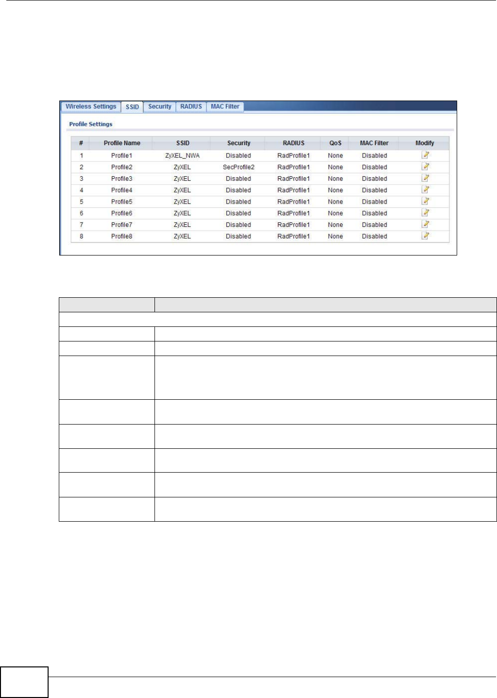
Chapter 6 Wireless LAN
NWA1120 Series User’s Guide
74
6.5 SSID Screen
Use this screen to view and modify the settings of the SSID profiles on the NWA. Click Wireless
LAN > SSID to display the screen as shown.
Figure 26 Wireless LAN > SSID
The following table describes the labels in this screen.
Table 15 Wireless LAN > SSID
LABEL DESCRIPTION
Profile Settings
# This field displays the index number of each SSID profile.
Profile Name This field displays the identification name of each SSID profile on the NWA.
SSID This field displays the SSID (Service Set IDentifier), that is, the name of the wireless
network to which a wireless client can connect. When a wireless client scans for an AP
to associate with, this is the name that is broadcast and seen in the wireless client
utility.
Security This field indicates which security profile is currently associated with each SSID
profile. See Section 6.6 on page 76 for more information.
RADIUS This field displays which RADIUS profile is currently associated with each SSID
profile, if you have a RADIUS server configured.
QoS This field displays the Quality of Service setting for this profile or NONE if QoS is not
configured on a profile.
MAC Filter This field displays which MAC filter profile is currently associated with each SSID
profile, or Disable if MAC filtering is not configured on an SSID profile.
Modify Click Edit to go to the SSID configuration screen where you can modify settings in an
SSID profile.
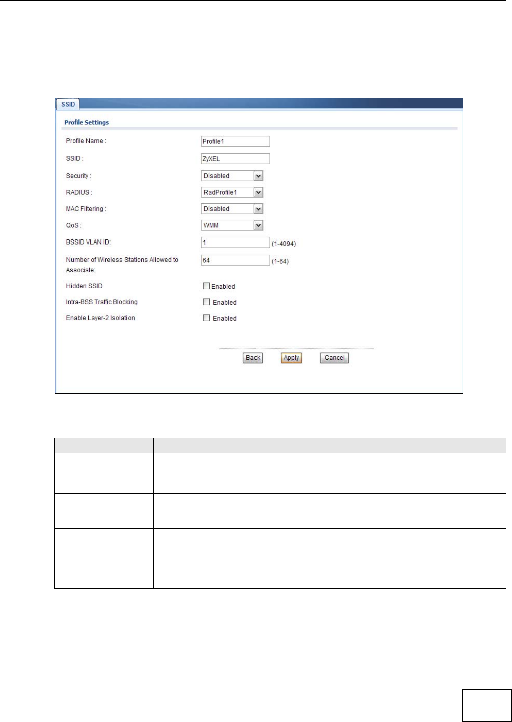
Chapter 6 Wireless LAN
NWA1120 Series User’s Guide 75
6.5.1 Configuring SSID
Use this screen to configure an SSID profile. In the Wireless LAN > SSID screen, click Edit next
to the SSID profile you want to configure to display the following screen.
Figure 27 SSID: Edit
The following table describes the labels in this screen.
Table 16 SSID: Edit
LABEL DESCRIPTION
Profile Name This is the name that identifying this profile.
SSID When a wireless client scans for an AP to associate with, this is the name that is
broadcast and seen in the wireless client utility.
Security Select a security profile to use with this SSID profile. See Section 6.6 on page 76 for
more information. If you do not want this profile to use wireless security, select
Disabled.
RADIUS Select a RADIUS profile from the drop-down list box, if you have a RADIUS server
configured. If you do not need to use RADIUS authentication, ignore this field. See
Section 6.7 on page 82 for more information.
MAC Filtering Select a MAC filter profile from the drop-down list box. If you do not want to use MAC
filtering on this profile, select Disabled.

Chapter 6 Wireless LAN
NWA1120 Series User’s Guide
76
6.6 Wireless Security Screen
Use this screen to choose the security mode for your NWA.
QoS Select the Quality of Service priority for this BSS’s traffic.
• If you select WMM from the QoS list, the priority of a data packet depends on the
packet’s IEEE 802.1q or DSCP header. If a packet has no WMM value assigned to
it, it is assigned the default priority.
•If you select WMM_VOICE, WMM_VIDEO, WMM_BESTEFFORT or
WMM_BACKGROUND, the NWA applies that QoS setting to all of that SSID’s
traffic.
•If you select None, the NWA applies no priority to traffic on this SSID.
Note: When you configure an SSID profile’s QoS settings, the NWA applies the same
QoS setting to all of the profile’s traffic.
BSSID VLAN ID Enter a VLAN ID for the SSID profile.
Packets coming from the WLAN using this SSID profile are tagged with the VLAN ID
number by the NWA.
Number of Wireless
Stations Allowed to
Associate
Use this field to set a maximum number of wireless stations that may connect to the
device.
Hidden SSID If you do not select the checkbox, the NWA broadcasts this SSID (a wireless client
scanning for an AP will find this SSID). Alternatively, if you select the checkbox, the
NWA hides this SSID (a wireless client scanning for an AP will not find this SSID).
Intra-BSS Traffic
Blocking Select this to prevent wireless clients in this profile’s BSS from communicating with
one another.
Enable Layer-2
Isolation Select this to enable layer-2 isolation for this profile. Wireless clients that connect to
the WLAN using this SSID can access only certain pre-defined devices. See Section
6.8 on page 84.
Intra-BSS traffic blocking is enabled automatically when you enable layer-2 isolation.
Back Click Back to return to the previous screen.
Apply Click Apply to save your changes.
Cancel Click Cancel to begin configuring this screen afresh.
Table 16 SSID: Edit (continued)
LABEL DESCRIPTION
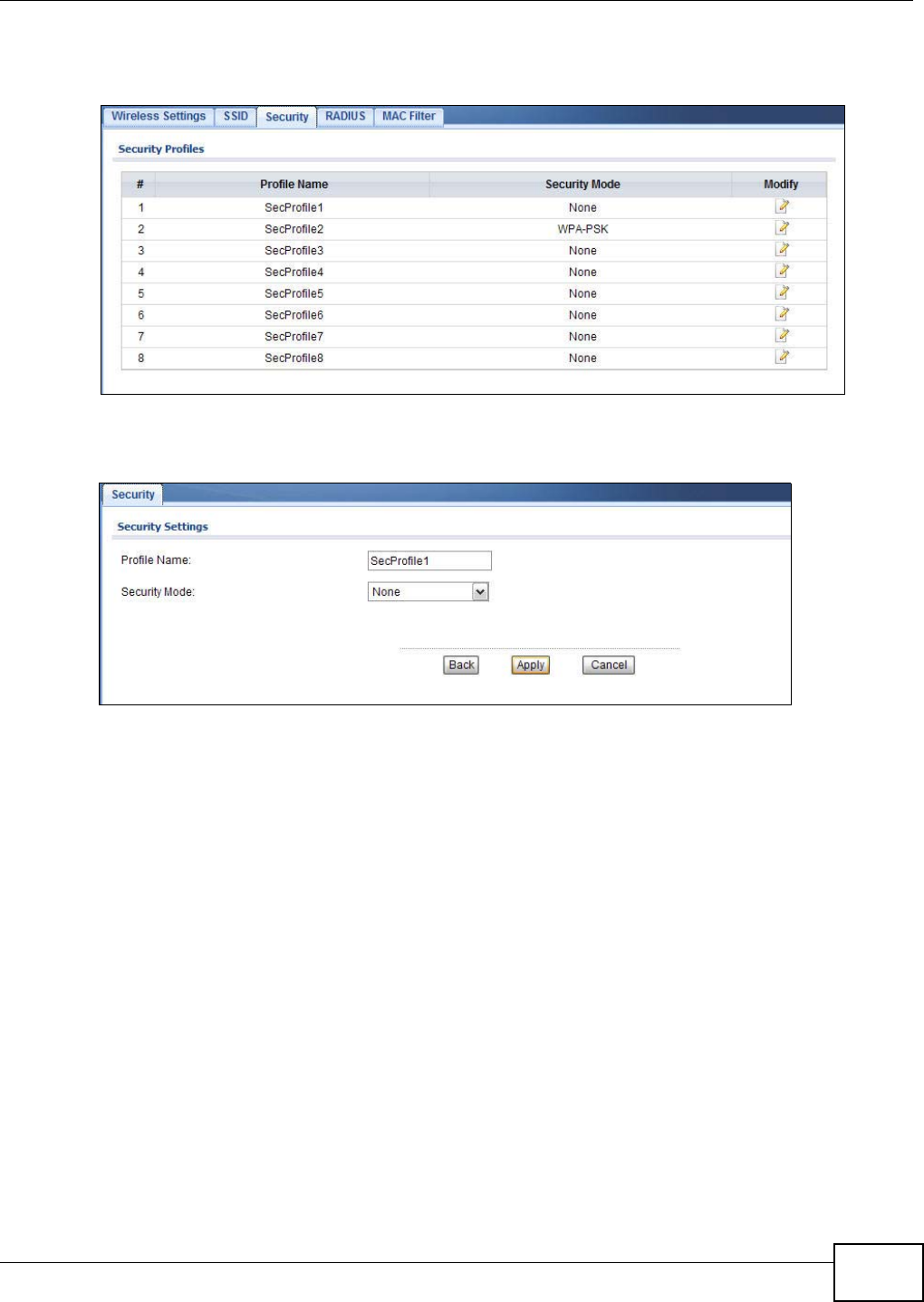
Chapter 6 Wireless LAN
NWA1120 Series User’s Guide 77
Click Wireless LAN > Security. Select the profile that you want to configure and click Edit.
Figure 28 Wireless > Security
The Security Settings screen varies depending upon the security mode you select.
Figure 29 Security: None
Note that some screens display differently depending on the operating mode selected in the
Wireless LAN > Wireless Settings, Network > Wireless LAN > Wireless Settings- 2.4G or
Network > Wireless LAN > Wireless Settings - 5G screen.
Note: You must enable the same wireless security settings on the NWA and on all wireless
clients that you want to associate with it.
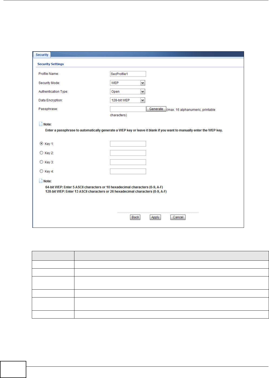
Chapter 6 Wireless LAN
NWA1120 Series User’s Guide
78
6.6.1 Security: WEP
Use this screen to use WEP as the security mode for your NWA. Select WEP in the Security Mode
field to display the following screen.
Figure 30 Security: WEP
The following table describes the labels in this screen.
Table 17 Security: WEP
LABEL DESCRIPTION
Profile Name This is the name that identifying this profile.
Security Mode Choose WEP in this field.
Authentication
Type Select Open or Shared from the drop-down list box.
Data Encryption Select 64-bit WEP or 128-bit WEP to enable data encryption.
Passphrase Enter the passphrase or string of text used for automatic WEP key generation on wireless
client adapters.
Generate Click this to get the keys from the Passphrase you entered.
Chapter 6 Wireless LAN
NWA1120 Series User’s Guide 79
6.6.2 Security: WPA, WPA2, WPA2-MIX
This screen varies depending on the operating mode you select in the Wireless LAN > Wireless
Settings screen.
6.6.2.1 Access Point
Use this screen to employ WPA or WPA2 as the security mode for your NWA that is in root AP,
MBSSID or repeater operating mode. Select WPA, WPA2 or WPA2-MIX in the Security Mode
field to display the following screen.
Figure 31 Security: WPA/WPA2 for Access Point
The following table describes the labels in this screen.
Key 1 to
Key 4
The WEP keys are used to encrypt data. Both the NWA and the wireless stations must use
the same WEP key for data transmission.
If you chose 64-bit WEP, then enter any 5 ASCII characters or 10 hexadecimal
characters ("0-9", "A-F").
If you chose 128-bit WEP, then enter 13 ASCII characters or 26 hexadecimal characters
("0-9", "A-F").
You can configure up to four keys, but only one key can be activated at any one time.
Back Click Back to return to the previous screen.
Apply Click Apply to save your changes.
Cancel Click Cancel to begin configuring this screen afresh.
Table 17 Security: WEP (continued)
LABEL DESCRIPTION
Table 18 Security: WPA/WPA2 for Access Point
LABEL DESCRIPTION
Security Settings
Profile Name This is the name that identifying this profile.
Security Mode Choose WPA, WPA2 or WPA-MIX in this field.
Rekey Options
Chapter 6 Wireless LAN
NWA1120 Series User’s Guide
80
6.6.2.2 Wireless Client
Use this screen to employ WPA or WPA2 as the security mode for your NWA that is in wireless client
operating mode. Select WPA or WPA2 in the Security Mode field to display the following screen.
Figure 32 Security: WPA for Wireless Client
Reauthentication
Time Specify how often wireless stations have to resend user names and passwords in order to
stay connected.
Enter a time interval between 100 and 3600 seconds. Alternatively, enter “0” to turn
reauthentication off.
Note: If wireless station authentication is done using a RADIUS server, the reauthentication
timer on the RADIUS server has priority.
Enable Group-Key
Update Select this option to have the NWA automatically disconnect a wireless station from the
wired network after a period of inactivity. The wireless station needs to enter the user
name and password again before access to the wired network is allowed.
Enter a time interval between 100 and 3600 seconds.
Back Click Back to return to the previous screen.
Apply Click Apply to save your changes.
Cancel Click Cancel to begin configuring this screen afresh.
Table 18 Security: WPA/WPA2 for Access Point (continued)
LABEL DESCRIPTION
Chapter 6 Wireless LAN
NWA1120 Series User’s Guide 81
The following table describes the labels in this screen.
6.6.3 Security: WPA-PSK, WPA2-PSK, WPA2-PSK-MIX
Use this screen to employ WPA-PSK, WPA2-PSK or WPA2-PSK-MIX as the security mode of your
NWA. Select WPA-PSK, WPA2-PSK or WPA2-PSK-MIX in the Security Mode field to display the
following screen.
Figure 33 Security: WPA-PSK, WPA2-PSK or WPA2-PSK-MIX
Table 19 Security: WPA/WPA2 for Wireless Client
LABEL DESCRIPTION
Security Settings
Profile Name This is the name that identifying this profile.
Security Mode Choose the same security mode used by the AP.
Data Encryption This shows the encryption method used by the NWA.
IEEE802.1x Authentication
Eap Type The options on the left refer to EAP methods. You can choose either TLS, LEAP, PEAP or
TTLS.
If you select TTLS or PEAP, the options on the right refer to authentication protocols. You
can choose between PAP, CHAP, MSCHAP, MSCHAPv2 and/or GTC.
User Information
Username
Login Name
Supply the user name of the account created in the RADIUS server.
Password Supply the password of the account created in the RADIUS server.
Certificate
User Certificate If you select TLS, enter the name of the certificate used to to verify the identity of clients.
Back Click Back to return to the previous screen.
Apply Click Apply to save your changes.
Cancel Click Cancel to begin configuring this screen afresh.
Chapter 6 Wireless LAN
NWA1120 Series User’s Guide
82
The following table describes the labels not previously discussed
6.7 RADIUS Screen
Use this screen to set up your NWA’s RADIUS server settings. Click Wireless LAN > RADIUS. The
screen appears as shown.
Figure 34 Wireless LAN > RADIUS
Table 20 Security: WPA-PSK, WPA2-PSK or WPA2-PSK-MIX
LABEL DESCRIPTION
Profile Name This is the name that identifying this profile.
Security Mode Choose WPA-PSK, WPA2-PSK or WPA2-PSK-MIX in this field.
Pre-Shared Key The encryption mechanisms used for WPA and WPA-PSK are the same. The only
difference between the two is that WPA-PSK uses a simple common password, instead
of user-specific credentials.
Type a pre-shared key from 8 to 63 case-sensitive ASCII characters (including spaces
and symbols).
Back Click Back to return to the previous screen.
Apply Click Apply to save your changes.
Cancel Click Cancel to begin configuring this screen afresh.
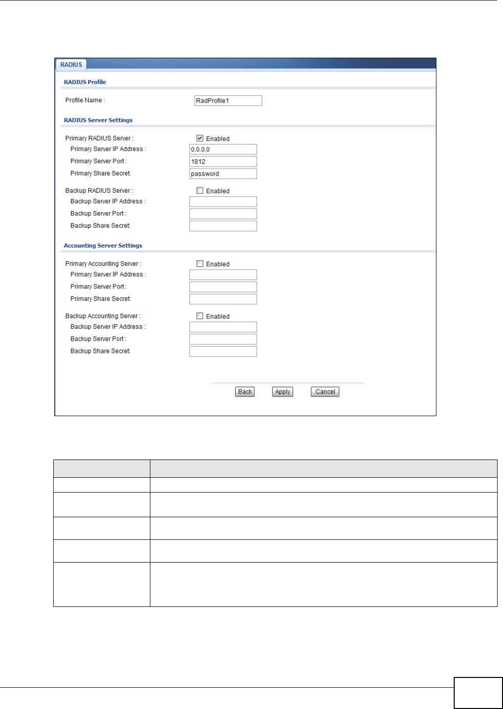
Chapter 6 Wireless LAN
NWA1120 Series User’s Guide 83
Select a profile you want to configure and click Edit.
Figure 35 Wireless LAN > RADIUS
The following table describes the labels in this screen.
Table 21 Wireless LAN > RADIUS
LABEL DESCRIPTION
Profile Name This is the name that identifying this RADIUS profile.
Primary RADIUS
Server Select the check box to enable user authentication through an external authentication
server.
Primary Server IP
Address Enter the IP address of the RADIUS server to be used for authentication.
Primary Server
Port Enter the port number of the RADIUS server to be used for authentication.
Primary Share
Secret Enter a password (up to 64 alphanumeric characters) as the key to be shared
between the external authentication server and the NWA. The key must be the same
on the external authentication server and your NWA. The key is not sent over the
network.

Chapter 6 Wireless LAN
NWA1120 Series User’s Guide
84
6.8 Layer-2 Isolation
Layer-2 isolation is used to prevent wireless clients associated with your NWA from communicating
with other wireless clients, APs, computers or routers in a network.
In the following example, layer-2 isolation is enabled on the NWA to allow a guest wireless client
(A) to access the main network router (B). The router provides access to the Internet and the
network printer (C) while preventing the client from accessing other computers and servers on the
Backup RADIUS
Server If the NWA cannot communicate with the primary RADIUS server, you can have the
NWA use a backup RADIUS server. Make sure the check boxe is selected if you want
to use the backup server.
The NWA will attempt to communicate three times before using the backup server.
Requests can be issued from the client interface to use the backup server. The length
of time for each authentication is decided by the wireless client or based on the
configuration of the Reauthentication Time field in the Wireless LAN > Security
screen.
Backup Server IP
Address Enter the IP address of the RADIUS server to be used for authentication.
Backup Server
Port Enter the port number of the RADIUS server to be used for authentication.
Backup Share
Secret Enter a password (up to 64 alphanumeric characters) as the key to be shared
between the external authentication server and the NWA. The key must be the same
on the external authentication server and your NWA. The key is not sent over the
network.
Primary Accounting
Server Select the check box to enable user accounting through an external authentication
server.
Primary Server IP
Address Enter the IP address of the external accounting server in dotted decimal notation.
Primary Server
Port Enter the port number of the external accounting server.
Primary Share
Secret Enter a password (up to 64 alphanumeric characters) as the key to be shared
between the external accounting server and the NWA. The key must be the same on
the external accounting server and your NWA. The key is not sent over the network.
Backup Accounting
Server If the NWA cannot communicate with the primary accounting server, you can have
the NWA use a backup accounting server. Make sure the check boxe is selected if you
want to use the backup server.
The NWA will attempt to communicate three times before using the backup server.
Backup Server IP
Address Enter the IP address of the external accounting server in dotted decimal notation.
Backup Server
Port Enter the port number of the external accounting server.
Backup Share
Secret Enter a password (up to 64 alphanumeric characters) as the key to be shared
between the external accounting server and the NWA. The key must be the same on
the external accounting and your NWA. The key is not sent over the network.
Back Click Back to return to the previous screen.
Apply Click Apply to save your changes.
Cancel Click Cancel to begin configuring this screen afresh.
Table 21 Wireless LAN > RADIUS (continued)
LABEL DESCRIPTION
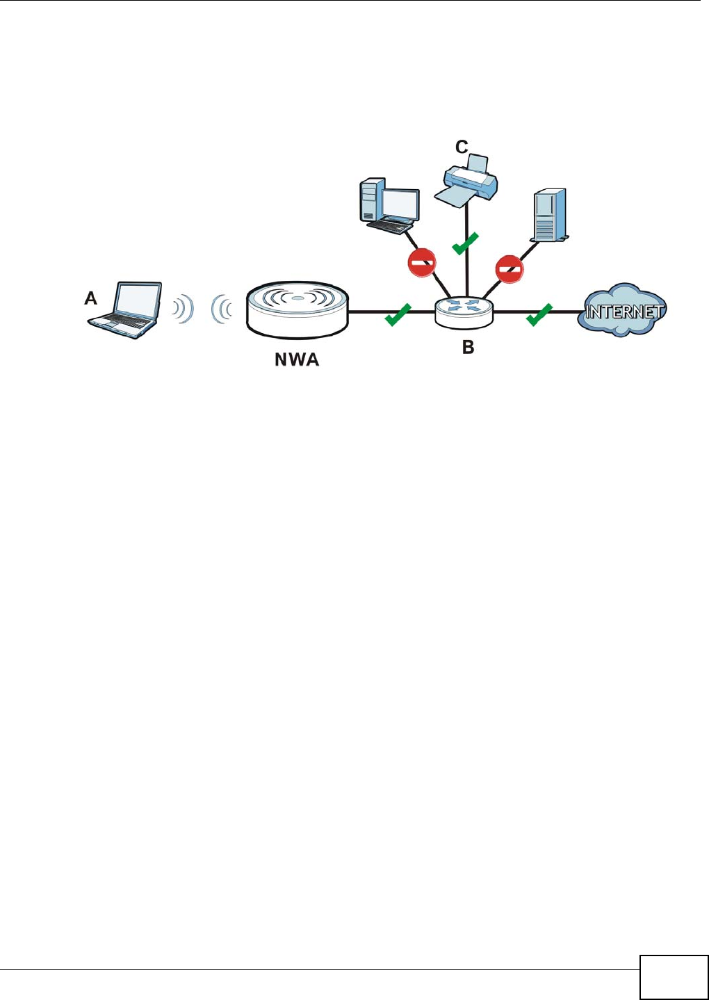
Chapter 6 Wireless LAN
NWA1120 Series User’s Guide 85
network. The client can communicate with other wireless clients only if Intra-BSS Traffic blocking is
disabled.
Note: Intra-BSS Traffic Blocking is activated when you enable layer-2 isolation.
Figure 36 Layer-2 Isolation Application
MAC addresses that are not listed in the layer-2 isolation table are blocked from communicating
with the NWA’s wireless clients except for broadcast packets. Layer-2 isolation does not check the
traffic between wireless clients that are associated with the same AP. Intra-BSS Traffic allows
wireless clients associated with the same AP to communicate with each other.
6.8.1 Layer-2 Isolation Screen
Use this screen to specify devices you want the users on your wireless networks to access. Click
Wireless LAN > Layer-2 Isolation. The screen displays as shown.
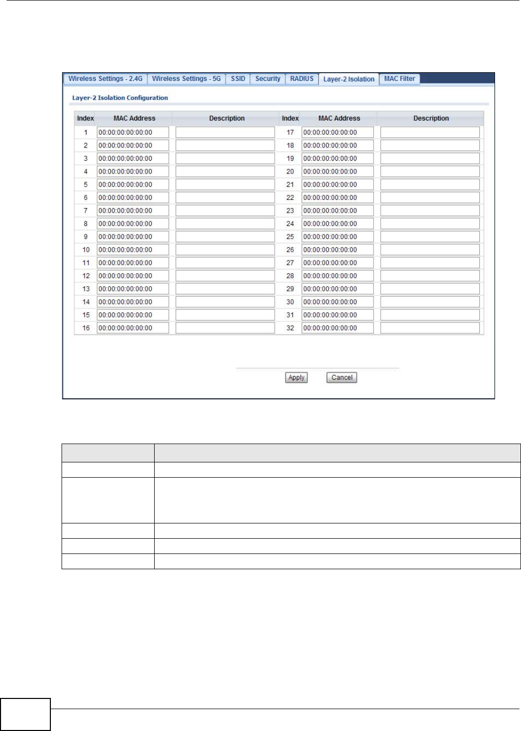
Chapter 6 Wireless LAN
NWA1120 Series User’s Guide
86
Note: You need to know the MAC address of each wireless client, AP, computer or router
that you want to allow to communicate with the NWA's wireless clients.
Figure 37 Wireless LAN > Layer-2 Isolation
The following table describes the labels in this screen.
6.9 MAC Filter Screen
Every Ethernet device has a unique MAC (Media Access Control) address. The MAC address is
assigned at the factory and consists of six pairs of hexadecimal characters, for example,
Table 22 Wireless LAN > Layer-2 Isolation
LABEL DESCRIPTION
Index This is the index number of the MAC address listed.
MAC Address Enter the MAC addresses of the wireless client, AP, computer or router that you want to
allow the associated wireless clients to have access to in these address fields. Enter the
MAC address in a valid MAC address format (six hexadecimal character pairs, for
example 12:34:56:78:9a:bc).
Description Enter a name to identify this device.
Apply Click Apply to save your changes.
Cancel Click Cancel to begin configuring this screen afresh.
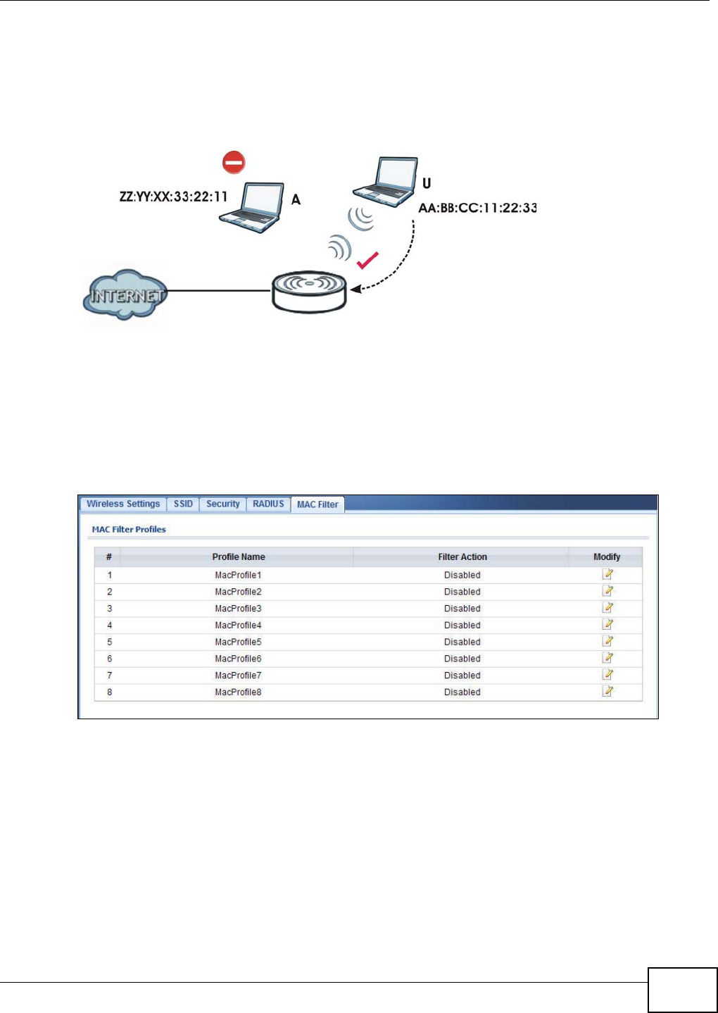
Chapter 6 Wireless LAN
NWA1120 Series User’s Guide 87
00:A0:C5:00:00:02. You need to know the MAC address of each device to configure MAC filtering
on the NWA.
The MAC filter function allows you to configure the NWA to grant access to the NWA from other
wireless devices (Allow Association) or exclude devices from accessing the NWA (Deny Association).
Figure 38 MAC Filtering
In the figure above, wireless client U is able to connect to the Internet because its MAC address is
in the allowed association list specified in the NWA. The MAC address of client A is either denied
association or is not in the list of allowed wireless clients specified in the NWA.
Use this screen to enable MAC address filtering in your NWA. You can specify MAC addresses to
either allow or deny association with your NWA. Click Wireless LAN > MAC Filter. The screen
displays as shown.
Figure 39 Wireless LAN > MAC Filter
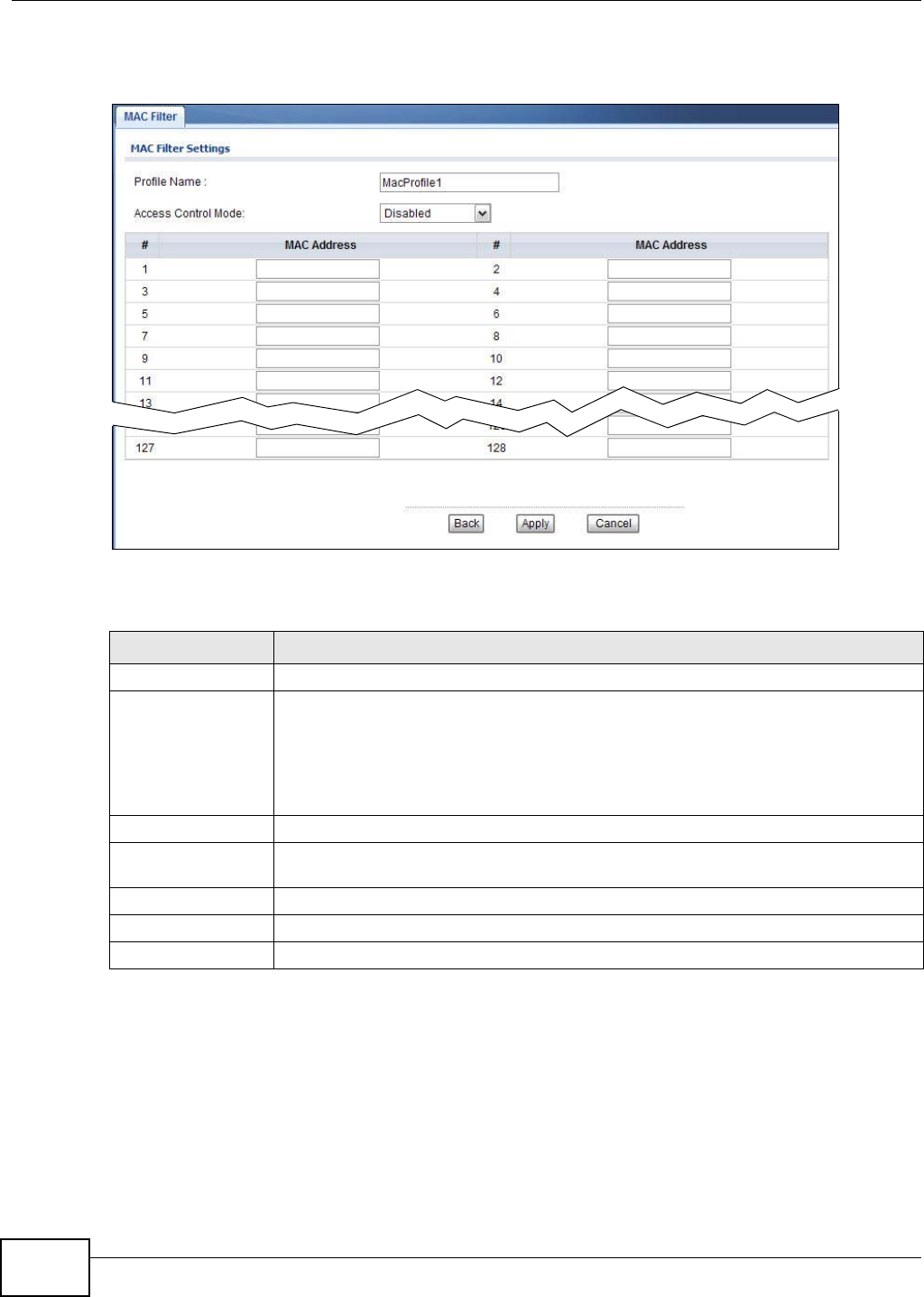
Chapter 6 Wireless LAN
NWA1120 Series User’s Guide
88
Select a profile you want to configure and click Edit.
Figure 40 MAC Filter: Edit
The following table describes the labels in this screen.
6.10 Technical Reference
This section provides technical background information about the topics covered in this chapter.
Refer to Appendix E on page 187 for further readings on Wireless LAN.
Table 23 Wireless LAN > MAC Filter
LABEL DESCRIPTION
Profile Name This is the name that identifying this profile.
Access Control Mode Select Disabled if you do not want to use this feature.
Select Allow to permit access to the NWA. MAC addresses not listed will be denied
access to the NWA.
Select Deny to block access to theNWA. MAC addresses not listed will be allowed to
access the NWA.
#This is the index number of the MAC address listed.
MAC Address Enter the MAC addresses (in XX:XX:XX:XX:XX:XX format) of the wireless station to be
allowed or denied access to the NWA.
Back Click Back to return to the previous screen.
Apply Click Apply to save your changes.
Cancel Click Cancel to begin configuring this screen afresh.

Chapter 6 Wireless LAN
NWA1120 Series User’s Guide 89
6.10.1 Additional Wireless Terms
Table 24 Additional Wireless Terms
6.10.2 WMM QoS
WMM (Wi-Fi MultiMedia) QoS (Quality of Service) ensures quality of service in wireless networks. It
controls WLAN transmission priority on packets to be transmitted over the wireless network.
WMM QoS prioritizes wireless traffic according to the delivery requirements of the individual and
applications. WMM QoS is a part of the IEEE 802.11e QoS enhancement to certified Wi-Fi wireless
networks.
On APs without WMM QoS, all traffic streams are given the same access priority to the wireless
network. If the introduction of another traffic stream creates a data transmission demand that
exceeds the current network capacity, then the new traffic stream reduces the throughput of the
other traffic streams.
The NWA uses WMM QoS to prioritize traffic streams according to the IEEE 802.1q or DSCP
information in each packet’s header. The NWA automatically determines the priority to use for an
individual traffic stream. This prevents reductions in data transmission for applications that are
sensitive to latency and jitter (variations in delay).
TERM DESCRIPTION
Intra-BSS Traffic This describes direct communication (not through the NWA) between two wireless
devices within a wireless network. You might disable this kind of communication to
enhance security within your wireless network.
RTS/CTS Threshold In a wireless network which covers a large area, wireless devices are sometimes not
aware of each other’s presence. This may cause them to send information to the AP
at the same time and result in information colliding and not getting through.
By setting this value lower than the default value, the wireless devices must
sometimes get permission to send information to the NWA. The lower the value, the
more often the devices must get permission.
If this value is greater than the fragmentation threshold value (see below), then
wireless devices never have to get permission to send information to the NWA.
Preamble A preamble affects the timing in your wireless network. There are two preamble
modes: long and short. If a device uses a different preamble mode than the NWA
does, it cannot communicate with the NWA.
Fragmentation
Threshold A small fragmentation threshold is recommended for busy networks, while a larger
threshold provides faster performance if the network is not very busy.
Roaming If you have two or more NWAs (or other wireless access points) on your wireless
network, you can enable this option so that wireless devices can change locations
without having to log in again. This is useful for devices, such as notebooks, that
move around a lot.
Antenna An antenna couples Radio Frequency (RF) signals onto air. A transmitter within a
wireless device sends an RF signal to the antenna, which propagates the signal
through the air. The antenna also operates in reverse by capturing RF signals from
the air.
Positioning the antennas properly increases the range and coverage area of a wireless
LAN.

Chapter 6 Wireless LAN
NWA1120 Series User’s Guide
90
6.10.2.1 WMM QoS Priorities
The following table describes the WMM QoS priority levels that the NWA uses.
6.10.3 Security Mode Guideline
The following is a general guideline in choosing the security mode for your NWA.
• Use WPA(2)-PSK if you have WPA(2)-aware wireless clients but no RADIUS server.
• Use WPA(2) security if you have WPA(2)-aware wireless clients and a RADIUS server. WPA has
user authentication and improved data encryption over WEP.
• Use WPA(2)-PSK if you have WPA(2)-aware wireless clients but no RADIUS server.
• If you don’t have WPA(2)-aware wireless clients, then use WEP key encrypting. A higher bit key
offers better security. You can manually enter 64-bit or 128-bit WEP keys.
More information on Wireless Security can be found in Appendix E on page 187.
Table 25 WMM QoS Priorities
Priority Level description
voice
(WMM_VOICE)
Typically used for traffic that is especially sensitive to jitter. Use this priority to
reduce latency for improved voice quality.
video
(WMM_VIDEO)
Typically used for traffic which has some tolerance for jitter but needs to be
prioritized over other data traffic.
best effort
(WMM_BESTEFFORT)
Typically used for traffic from applications or devices that lack QoS capabilities. Use
best effort priority for traffic that is less sensitive to latency, but is affected by long
delays, such as Internet surfing.
background
(WMM_BACKGROUND)
This is typically used for non-critical traffic such as bulk transfers and print jobs
that are allowed but that should not affect other applications and users. Use
background priority for applications that do not have strict latency and throughput
requirements.
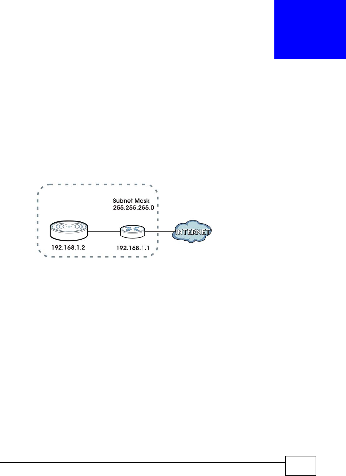
NWA1120 Series User’s Guide 91
CHAPTER 7
LAN
7.1 Overview
This chapter describes how you can configure the IP address of your NWA.
The Internet Protocol (IP) address identifies a device on a network. Every networking device
(including computers, servers, routers, printers, etc.) needs an IP address to communicate across
the network. These networking devices are also known as hosts.
Figure 41 IPv4 Setup
The figure above illustrates one possible setup of your NWA. The gateway IPv4 address is
192.168.1.1 and the IPv4 address of the NWA is 192.168.1.2 (default). The gateway and the device
must belong in the same subnet mask to be able to communicate with each other.
7.2 What You Can Do in this Chapter
Use the LAN IP screen to configure the IP address of your NWA (see Section 7.4 on page 93).
7.3 What You Need to Know
The Ethernet parameters of the NWA are preset in the factory with the following values:
1IP address of 192.168.1.2
2Subnet mask of 255.255.255.0 (24 bits)

Chapter 7 LAN
NWA1120 Series User’s Guide
92
IPv6
IPv6 (Internet Protocol version 6), is designed to enhance IP address size and features. The
increase in IPv6 address size to 128 bits (from the 32-bit IPv4 address) allows up to 3.4 x 1038 IP
addresses.
IPv6 Addressing
The 128-bit IPv6 address is written as eight 16-bit hexadecimal blocks separated by colons (:). This
is an example IPv6 address 2001:0db8:1a2b:0015:0000:0000:1a2f:0000.
IPv6 addresses can be abbreviated in two ways:
• Leading zeros in a block can be omitted. So 2001:0db8:1a2b:0015:0000:0000:1a2f:0000 can
be written as 2001:db8:1a2b:15:0:0:1a2f:0.
• Any number of consecutive blocks of zeros can be replaced by a double colon. A double colon can
only appear once in an IPv6 address. So 2001:0db8:0000:0000:1a2f:0000:0000:0015 can be
written as 2001:0db8::1a2f:0000:0000:0015, 2001:0db8:0000:0000:1a2f::0015,
2001:db8::1a2f:0:0:15 or 2001:db8:0:0:1a2f::15.
Prefix and Prefix Length
Similar to an IPv4 subnet mask, IPv6 uses an address prefix to represent the network address. An
IPv6 prefix length specifies how many most significant bits (start from the left) in the address
compose the network address. The prefix length is written as “/x” where x is a number. For
example,
2001:db8:1a2b:15::1a2f:0/32
means that the first 32 bits (2001:db8) is the subnet prefix.
Link-local Address
A link-local address uniquely identifies a device on the local network (the LAN). It is similar to a
“private IP address” in IPv4. You can have the same link-local address on multiple interfaces on a
device. A link-local unicast address has a predefined prefix of fe80::/10. The link-local unicast
address format is as follows.
Table 26 Link-local Unicast Address Format
Global Address
A global address uniquely identifies a device on the Internet. It is similar to a “public IP address” in
IPv4. A global unicast address starts with a 2 or 3.
1111 1110 10 0 Interface ID
10 bits 54 bits 64 bits
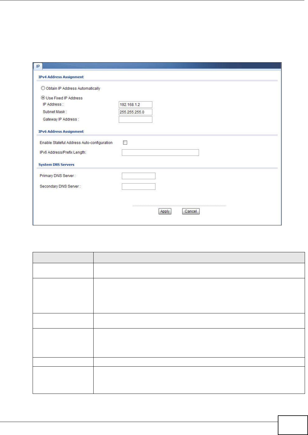
Chapter 7 LAN
NWA1120 Series User’s Guide 93
7.4 LAN IP Screen
Use this screen to configure the IP address for your NWA. Click Network > LAN to display the
following screen.
Figure 42 LAN IP
The following table describes the labels in this screen.
Table 27 LAN IP
LABEL DESCRIPTION
IPv4 Address
Assignment
Obtain IP Address
Automatically Select this option if your NWA is using a dynamically assigned IPv4 address from a
DHCP server each time.
Note: You must know the IP address assigned to the NWA (by the DHCP server) to
access the NWA again.
Use Fixed IP Address Select this option if your NWA is using a static IPv4 address. When you select this
option, fill in the fields below.
IP Address Enter the IP address of your NWA in dotted decimal notation.
Note: If you change the NWA's IP address, you must use the new IP address if you
want to access the web configurator again.
Subnet Mask Type the subnet mask.
Gateway IP
Address Type the IPv4 address of the gateway. The gateway is an immediate neighbor of your
NWA that will forward the packet to the destination. On the LAN, the gateway must
be a router on the same segment as your NWA; over the WAN, the gateway must be
the IP address of one of the remote nodes.

Chapter 7 LAN
NWA1120 Series User’s Guide
94
IPv6 Address
Assignment
Enable Stateful
Address Auto-
configuration
Select this to turn on IPv6 stateful autoconfiguration to have the NWA obtain an IPv6
global address from a DHCPv6 server in your network.
IPv6 Address/Prefix
Length Enter your IPv6 address and prefix manually.
System DNS Servers
Primary DNS Server Enter the IPv4 address of the first DNS (Domain Name Service) server, if provided.
Secondary DNS Server Enter the IPv4 address of the second DNS (Domain Name Service) server address, if
provided.
Apply Click Apply to save your changes.
Cancel Click Cancel to begin configuring this screen afresh.
Table 27 LAN IP (continued)
LABEL DESCRIPTION
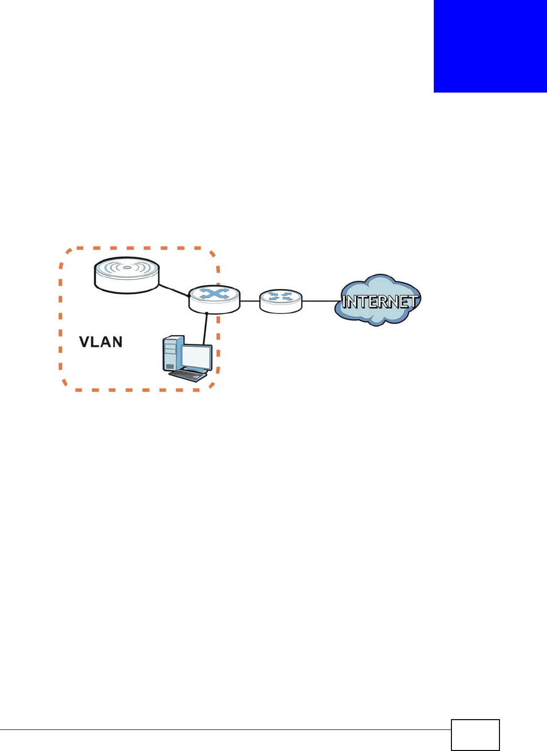
NWA1120 Series User’s Guide 95
CHAPTER 8
VLAN
8.1 Overview
This chapter discusses how to configure the NWA’s VLAN settings.
Figure 43 Management VLAN Setup
In the figure above, to access and manage the NWA from computer A, the NWA and switch B’s
ports to which computer A and the NWA are connected should be in the same VLAN.
8.1.1 What You Can Do in This Chapter
The VLAN screens let you set up the NWA’s mangement VLAN (Section 8.3 on page 96).
8.2 What You Need to Know
Introduction to VLANs
A Virtual Local Area Network (VLAN) allows a physical network to be partitioned into multiple logical
networks. Devices on a logical network belong to one group. A device can belong to more than one
group. With VLAN, a device cannot directly talk to or hear from devices that are not in the same
group(s); the traffic must first go through a router.
In Multi-Tenant Unit (MTU) applications, VLAN is vital in providing isolation and security among the
subscribers. When properly configured, VLAN prevents one subscriber from accessing the network
resources of another on the same LAN, thus a user will not see the printers and hard disks of
another user in the same building.
A
B
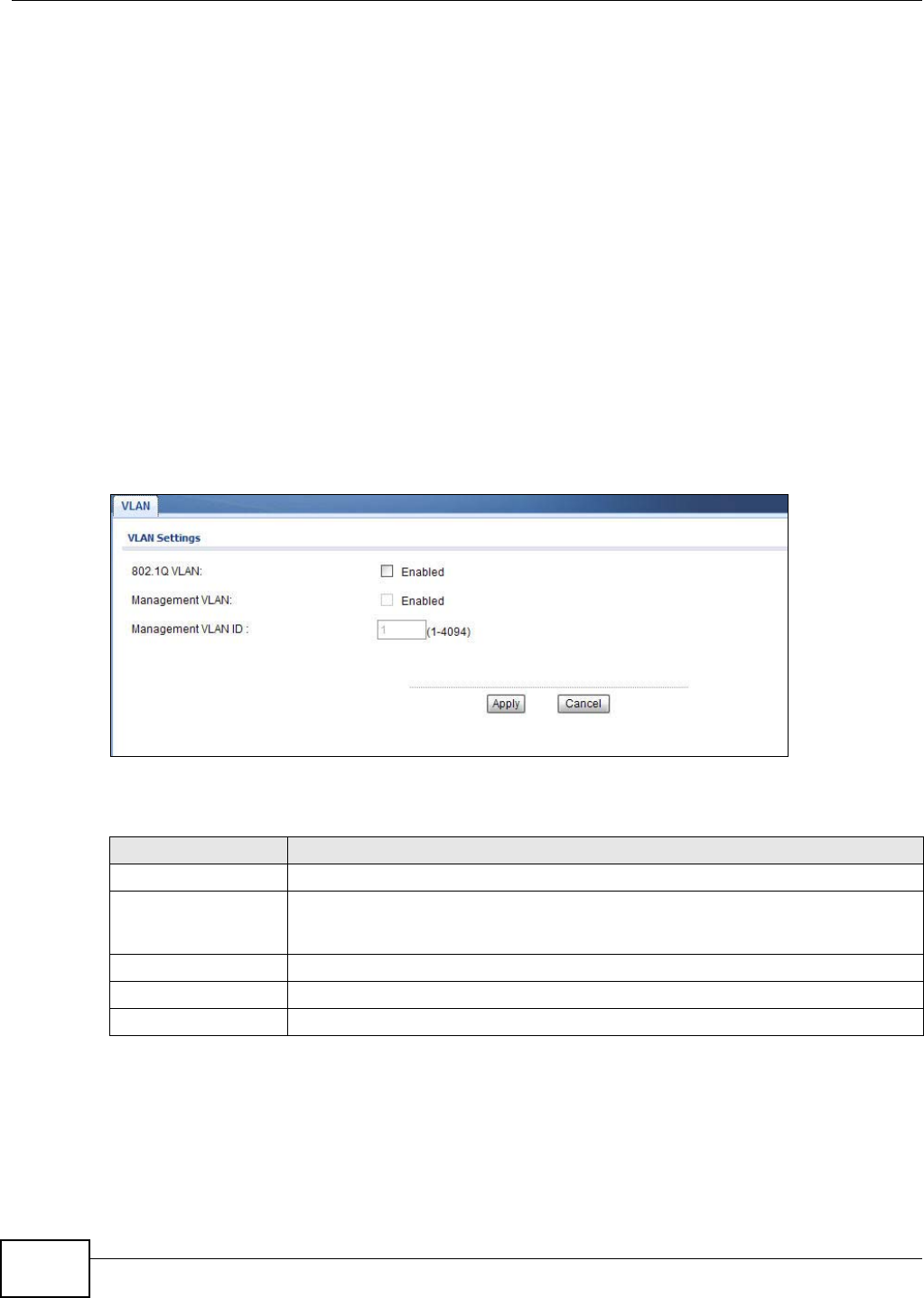
Chapter 8 VLAN
NWA1120 Series User’s Guide
96
VLAN also increases network performance by limiting broadcasts to a smaller and more
manageable logical broadcast domain. In traditional switched environments, all broadcast packets
go to each and every individual port. With VLAN, all broadcasts are confined to a specific broadcast
domain.
IEEE 802.1Q Tag
The IEEE 802.1Q standard defines an explicit VLAN tag in the MAC header to identify the VLAN
membership of a frame across bridges. A VLAN tag includes the 12-bit VLAN ID and 3-bit user
priority. The VLAN ID associates a frame with a specific VLAN and provides the information that
devices need to process the frame across the network.
8.3 VLAN Screen
Use this screen to set up the VLAN for managing the NWA. Click Network > VLAN to display the
screen as shown.
Figure 44 Network > VLAN
The following table describes the labels in this screen.
Figure 45 Network > VLAN
LABEL DESCRIPTION
802.1Q VLAN Select this to enable VLAN tagging on the NWA.
Management VLAN Select this to enable VLAN management. Only traffic tagged with the management
VLAN ID can access the NWA. At least one device in your network must belong to the
VLAN specified below in order to manage the NWA.
Management VLAN ID Enter a number from 1 to 4094 to define the NWA’s management VLAN group.
Apply Click Apply to save your changes.
Cancel Click Cancel to begin configuring this screen afresh.
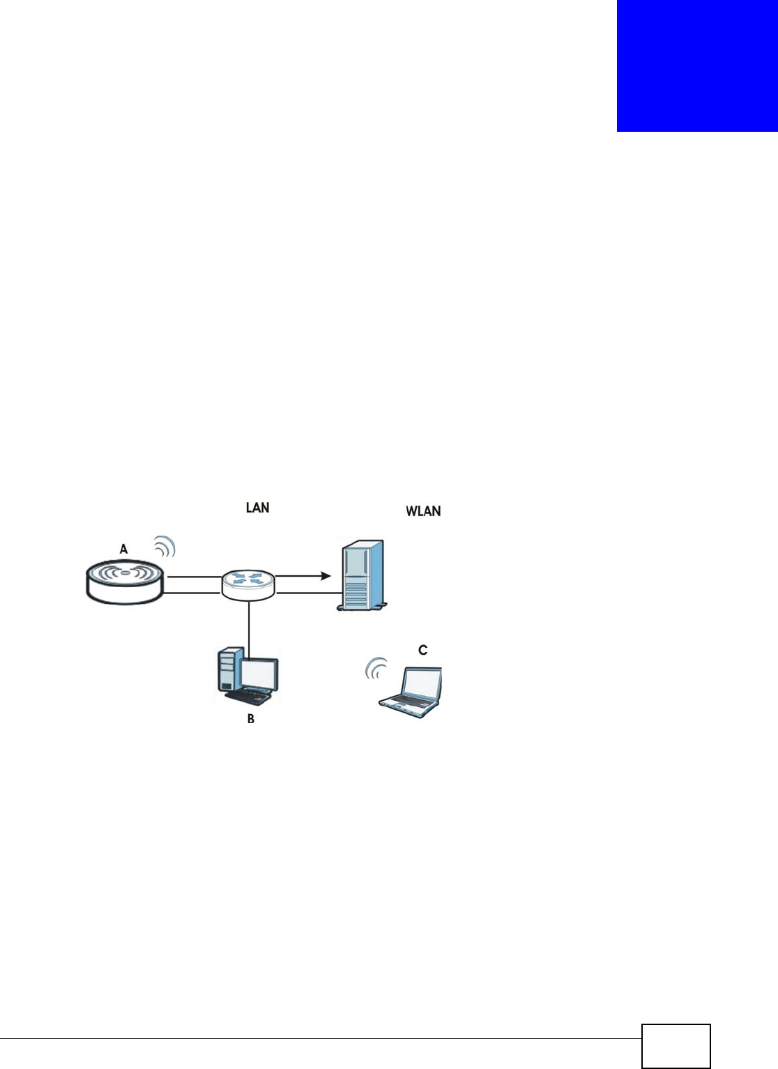
NWA1120 Series User’s Guide 97
CHAPTER 9
System
9.1 Overview
This chapter shows you how to enable remote management of your NWA. It provides information
on determining which services or protocols can access which of the NWA’s interfaces.
Remote Management allows a user to administrate the device over the network. You can manage
your NWA from a remote location via the following interfaces:
•WLAN
•LAN
•Both WLAN and LAN
• Neither (Disable)
Figure 46 Remote Management Example
In the figure above, the NWA (A) is being managed by a desktop computer (B) connected via LAN
(Land Area Network). It is also being accessed by a notebook (C) connected via WLAN (Wireless
LAN).
9.2 What You Can Do in this Chapter
•Use the WWW screen to configure through which interface(s) and from which IP address(es) you
can use the Web Browser to manage the NWA (see Section 9.4 on page 100).
•Use the Certificates screen to delete and import certificates (seen Section 9.5 on page 101).
•Use the Telnet screen to configure through which interface(s) and from which IP address(es)
you can use Telnet to manage the NWA. A Telnet connection is prioritized by the NWA over other
remote management sessions (see Section 9.6 on page 102).

Chapter 9 System
NWA1120 Series User’s Guide
98
•Use the SNMP screen to configure through which interface(s) and from which IP address(es) a
network systems manager can access the NWA (see Section 9.7 on page 104).
•Use the FTP screen to configure through which interface(s) and from which IP address(es) you
can use File Transfer Protocol (FTP) to manage the NWA. You can use FTP to upload the latest
firmware for example (see Section 9.8 on page 106).
9.3 What You Need To Know
WWW
The World Wide Web allows you to access files hosted in a remote server. For example, you can
view text files (usually referred to as ‘pages’) using your web browser via HyperText Transfer
Protocol (HTTP).
Telnet
Telnet is short for Telecommunications Network, which is a client-side protocol that enables you to
access a device over the network.
FTP
File Transfer Protocol (FTP) allows you to upload or download a file or several files to and from a
remote location using a client or the command console.
SNMP
Simple Network Management Protocol (SNMP) is a member of the TCP/IP protocol suite used for
exchanging management information between network devices.
Your NWA supports SNMP agent functionality, which allows a manager station to manage and
monitor the NWA through the network. The NWA supports SNMP version one (SNMPv1), version
two (SNMPv2c) and version three (SNMPv3).
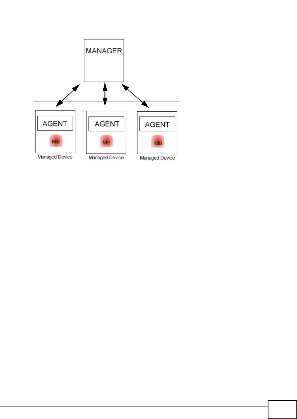
Chapter 9 System
NWA1120 Series User’s Guide 99
The next figure illustrates an SNMP management operation.
Figure 47 SNMP Management Mode
An SNMP managed network consists of two main types of component: agents and a manager.
An agent is a management software module that resides in a managed device (the NWA). An agent
translates the local management information from the managed device into a form compatible with
SNMP. The manager is the console through which network administrators perform network
management functions. It executes applications that control and monitor managed devices.
SNMP allows a manager and agents to communicate for the purpose of accessing information such
as packets received, node port status, etc.
SNMP v3 and Security
SNMP v3 enhances security for SNMP management. SNMP managers can be required to
authenticate with agents before conducting SNMP management sessions.
Security can be further enhanced by encrypting the SNMP messages sent from the managers.
Encryption protects the contents of the SNMP messages. When the contents of the SNMP messages
are encrypted, only the intended recipients can read them.
Remote Management Limitations
Remote management over LAN or WLAN will not work when:
• You have disabled that service in one of the remote management screens.
• The IP address in the Secured Client IP Address field does not match the client IP address. If
it does not match, the NWA will disconnect the session immediately.
• You may only have one remote management session running at one time. The NWA
automatically disconnects a remote management session of lower priority when another remote
management session of higher priority starts. The priorities for the different types of remote
management sessions are as follows:
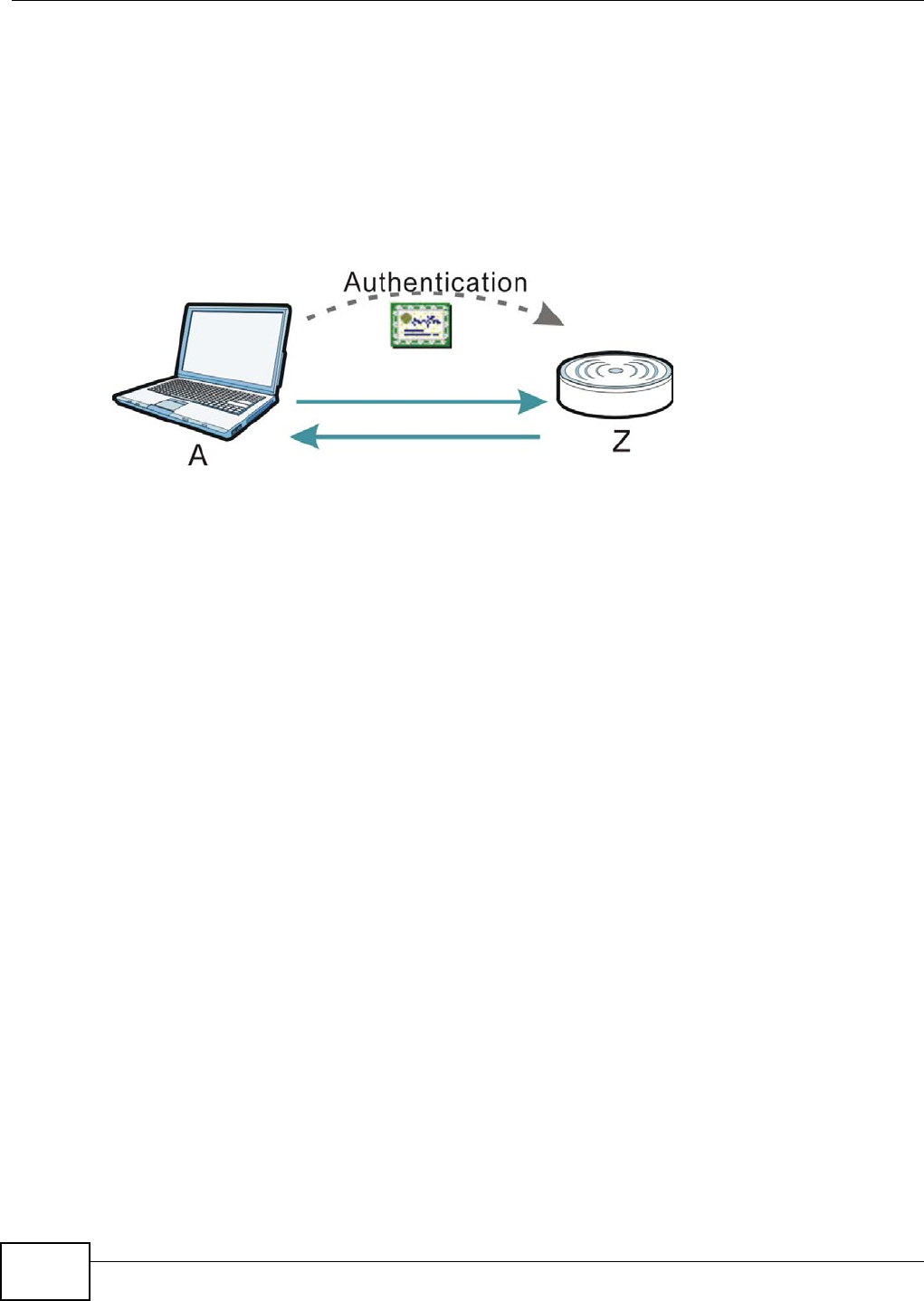
Chapter 9 System
NWA1120 Series User’s Guide
100
1Telnet
2HTTP
Certificate
A certificate contains the certificate owner’s identity and public key. Certificates provide a way to
exchange public keys for use in authentication.
Figure 48 Certificates Example
In the figure above, the NWA (Z) checks the identity of the notebook (A) using a certificate before
granting access to the network.
The certification authority certificate that you can import to your NWA should be in PFX PKCS#12
file format. This format referred to as the Personal Information Exchange Syntax Standard is
comprised of a private key-public certificate pair that is further encrypted with a password. Before
you import a certificate into the NWA, you should verify that you have the correct certificate.
Key distribution is simple and very secure since you can freely distribute public keys and you never
need to transmit private keys.
9.4 WWW Screen
Use this screen to configure your NWA via the World Wide Web (WWW) using a Web browser. This
lets you specify which IP addresses or computers are able to communicate with and access the
NWA.
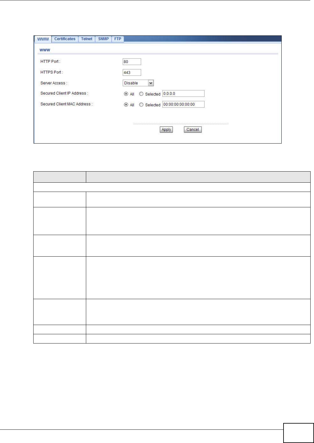
Chapter 9 System
NWA1120 Series User’s Guide 101
To change your NWA’s WWW settings, click System > WWW. The following screen shows.
Figure 49 System > WWW
The following table describes the labels in this screen.
9.5 Certificates Screen
Use this screen to delete or import certificates.
Table 28 System > WWW
LABEL DESCRIPTION
WWW
HTTP Port You may change the server port number for a service if needed, however you must use
the same port number in order to use that service for remote management.
HTTPS Port The HTTPS proxy server listens on port 443 by default. If you change the HTTPS proxy
server port to a different number on the NWA, for example 8443, then you must notify
people who need to access the NWA web configurator to use “https://NWA IP
Address:8443” as the URL.
Server Access Select the interface(s) through which a computer may access the NWA using WWW and
to which the IP and MAC filtering rules you specified below are applied. Otherwise, select
Disable to allow any computer to access the NWA through any interface using WWW.
Secured Client IP
Address A secured client is a “trusted” computer that is allowed to communicate with the NWA
using this service.
Select All to allow any computer to access the NWA using this service.
Choose Selected to just allow the computer with the IP address that you specify to
access the NWA using this service.
Secured Client
MAC Address Select All to allow any computer to access the NWA using this service.
Choose Selected to just allow the computer with the MAC address that you specify to
access the NWA using this service.
Apply Click Apply to save your customized settings.
Cancel Click Cancel to begin configuring this screen afresh.
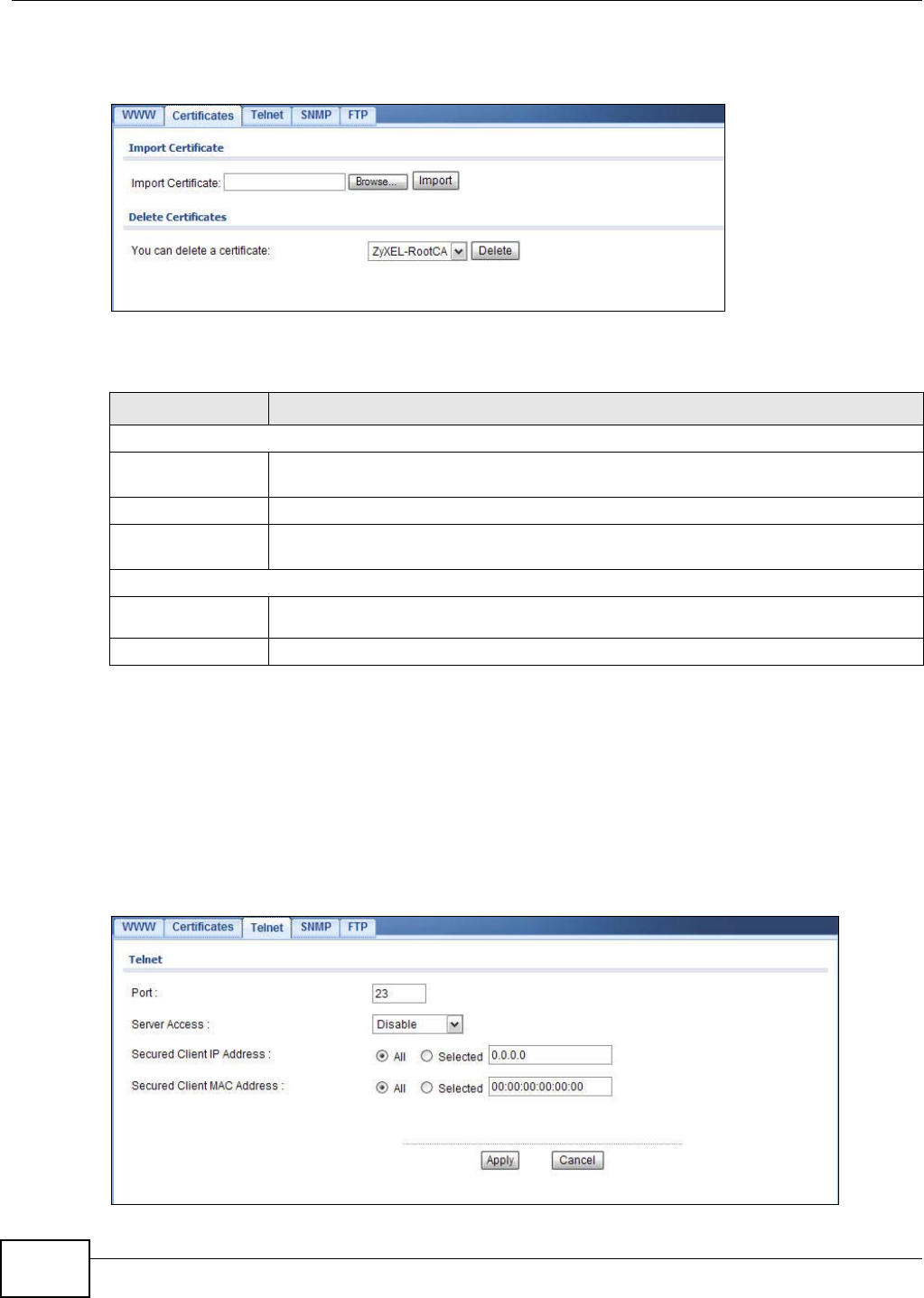
Chapter 9 System
NWA1120 Series User’s Guide
102
Click System > Certificates. The following screen shows.
Figure 50 System > Certificates
The following table describes the labels in this screen.
9.6 Telnet Screen
Use this screen to configure your NWA for remote Telnet access. You can use Telnet to access the
NWA’s Command Line Interface (CLI).
Click System > Telnet. The following screen displays.
Figure 51 System > Telnet
Table 29 System > Certificates
LABEL DESCRIPTION
Import Certificate
Import
Certificate Enter the location of a previously-saved certificate to upload to the NWA. Alternatively,
click the Browse button to locate a list.
Browse Click this button to locate a previously-saved certificate to upload to the NWA.
Import Click this button to upload the previously-saved certificate displayed in the Import
Certificate field to the NWA.
Delete Certificate
You can delete a
certificate Select the certificate from the list that you want to delete.
Delete Click this to delete the selected certificate.

Chapter 9 System
NWA1120 Series User’s Guide 103
The following table describes the labels in this screen.
Table 30 System > Telnet
LABEL DESCRIPTION
TELNET
Port You can change the server port number for a service if needed, however you must use
the same port number in order to use that service for remote management.
Server Access Select the interface(s) through which a computer may access the NWA using Telnet and
to which the IP and MAC filtering rules you specified below are applied. Otherwise, select
Disable to allow any computer to access the NWA through any interface using Telnet.
Secured Client IP
Address A secured client is a “trusted” computer that is allowed to communicate with the NWA
using this service.
Select All to allow any computer to access the NWA using this service.
Choose Selected to just allow the computer with the IP address that you specify to
access the NWA using this service.
Secured Client
MAC Address Select All to allow any computer to access the NWA using this service.
Choose Selected to just allow the computer with the MAC address that you specify to
access the NWA using this service.
Apply Click Apply to save your customized settings.
Cancel Click Cancel to begin configuring this screen afresh.
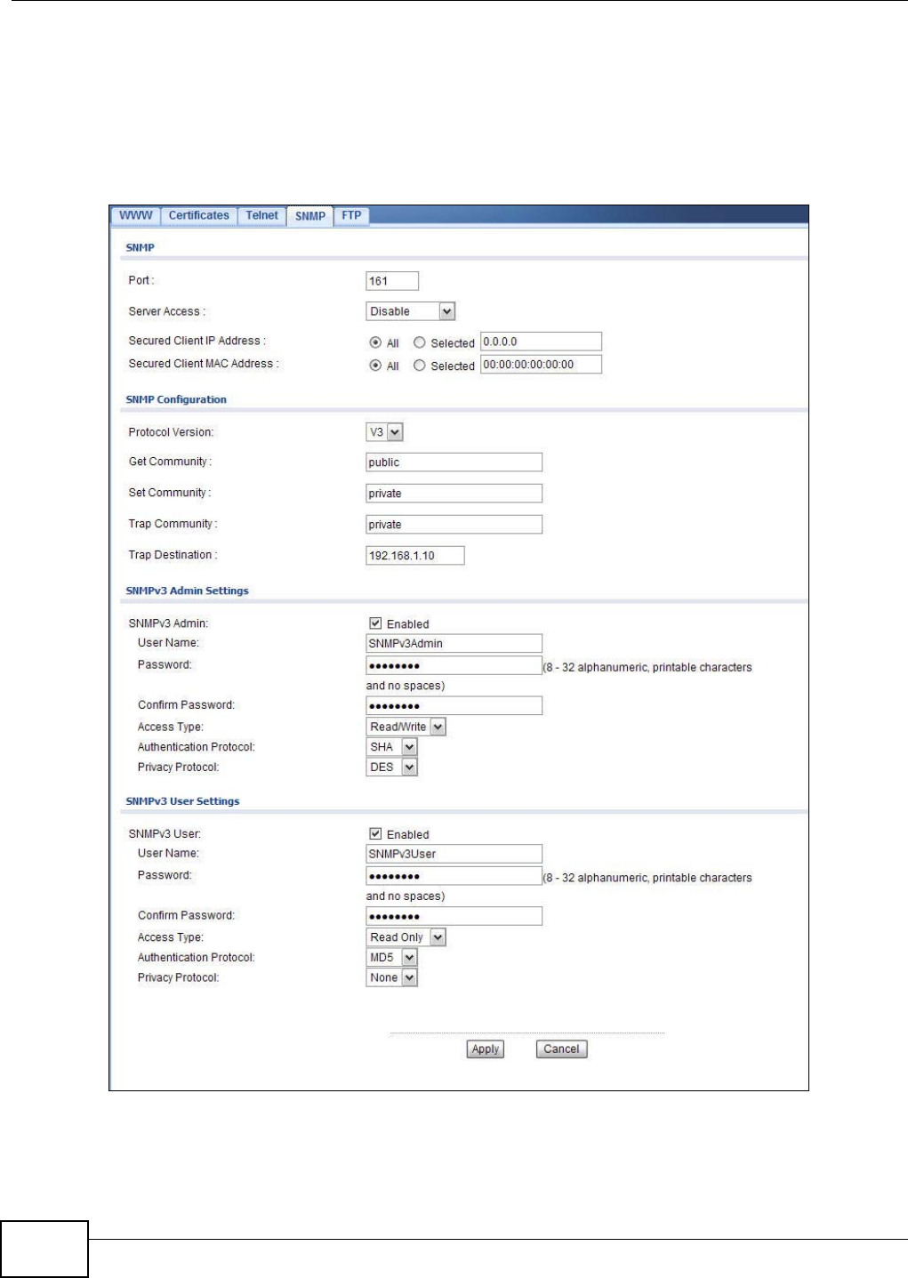
Chapter 9 System
NWA1120 Series User’s Guide
104
9.7 SNMP Screen
Use this screen to have a manager station administrate your NWA over the network and configure
SNMP accounts on the SNMP v3 manager. An SNMP administrator/user is an SNMP manager. To
change your NWA’s SNMP settings, click System > SNMP. The following screen displays.
Figure 52 System > SNMP

Chapter 9 System
NWA1120 Series User’s Guide 105
The following table describes the labels in this screen.
Table 31 System > SNMP
LABEL DESCRIPTION
SNMP
Port You can change the server port number for a service if needed, however you must use
the same port number in order to use that service for remote management.
Server Access Select the interface(s) through which a computer may access the NWA using SNMP and
to which the IP and MAC filtering rules you specified below are applied. Otherwise,
select Disable to allow any computer to access the NWA through any interface using
SNMP.
Secured Client IP
Address A secured client is a “trusted” computer that is allowed to communicate with the NWA
using this service.
Select All to allow any computer to access the NWA using this service.
Choose Selected to just allow the computer with the IP address that you specify to
access the NWA using this service.
Secured Client MAC
Address Select All to allow any computer to access the NWA using this service.
Choose Selected to just allow the computer with the MAC address that you specify to
access the NWA using this service.
SNMP Configuration
Protocol Version Select the SNMP version for the NWA, which you allow the SNMP manager to use to
access the NWA.
The SNMP version on the NWA must match the version on the SNMP manager.
Get Community Enter the Get Community, which is the password for the incoming Get and GetNext
requests from the management station.
Set Community Enter the Set community, which is the password for incoming Set requests from the
management station.
Trap Community Type the trap community, which is the password sent with each trap to the SNMP
manager.
Trap Destination Type the IP address of the station to send your SNMP traps to.
SNMPv3 Admin
Settings
SNMPv3 Admin Select the check box to enable the SNMP administrator account for authentication with
SNMP managers using SNMP v3.
User Name Specify the user name of the SNMP administrator account.
Password Enter the password for SNMP administrator authentication.
Confirm Password Retype the password for confirmation.
Access Type Specify the SNMP administrator’s access rights to MIBs.
Read/Write - The SNMP administrator has read and write rights, meaning that the
user can create and edit the MIBs on the NWA.
Read Only - The SNMP administrator has read rights only, meaning the user can collect
information from the NWA.
Authentication
Protocol Select an authentication algorithm used for SNMP communication with the SNMP
administrator.
MD5 (Message Digest 5) and SHA (Secure Hash Algorithm) are hash algorithms used
to authenticate SNMP data. SHA authentication is generally considered stronger than
MD5, but is slower.

Chapter 9 System
NWA1120 Series User’s Guide
106
9.8 FTP Screen
Use this screen to upload and download the NWA’s firmware using FTP. To use this feature, your
computer must have an FTP client.
Privacy Protocol Specify the encryption method used for SNMP communication with the SNMP
administrator.
DES - Data Encryption Standard is a widely used (but breakable) method of data
encryption. It applies a 56-bit key to each 64-bit block of data.
AES - Advanced Encryption Standard is another method for data encryption that also
uses a secret key. AES applies a 128-bit key to 128-bit blocks of data.
SNMPv3 User
Settings
SNMPv3 User Select the check box to enable the SNMP user account for authentication with SNMP
managers using SNMP v3.
User Name Specify the user name of the SNMP user account.
Password Enter the password for SNMP user authentication.
Confirm Password Retype the password for confirmation.
Access Type Specify the SNMP user’s access rights to MIBs.
Read Only - The SNMP user has read rights only, meaning the user can collect
information from the NWA.
Read/Write - The SNMP user has read and write rights, meaning that the user can
create and edit the MIBs on the NWA.
Authentication
Protocol Select an authentication algorithm used for SNMP communication with the SNMP user.
MD5 (Message Digest 5) and SHA (Secure Hash Algorithm) are hash algorithms used
to authenticate SNMP data. SHA authentication is generally considered stronger than
MD5, but is slower.
Privacy Protocol Specify the encryption method used for SNMP communication with the SNMP user.
DES - Data Encryption Standard is a widely used (but breakable) method of data
encryption. It applies a 56-bit key to each 64-bit block of data.
AES - Advanced Encryption Standard is another method for data encryption that also
uses a secret key. AES applies a 128-bit key to 128-bit blocks of data.
Apply Click Apply to save your customized settings.
Cancel Click Cancel to begin configuring this screen afresh.
Table 31 System > SNMP (continued)
LABEL DESCRIPTION
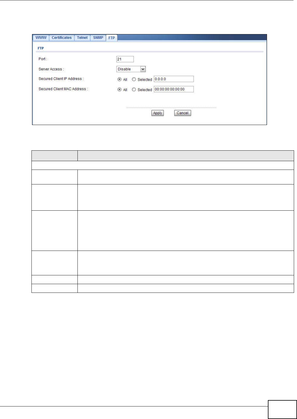
Chapter 9 System
NWA1120 Series User’s Guide 107
To change your NWA’s FTP settings, click System > FTP. The following screen displays.
Figure 53 System > FTP
The following table describes the labels in this screen.
9.9 Technical Reference
This section provides some technical background information about the topics covered in this
chapter.
9.9.1 MIB
Managed devices in an SMNP managed network contain object variables or managed objects that
define each piece of information to be collected about a device. Examples of variables include such
Table 32 System > FTP
LABEL DESCRIPTION
FTP
Port You may change the server port number for a service if needed, however you must use
the same port number in order to use that service for remote management.
Server Access Select the interface(s) through which a computer may access the NWA using this service
and to which the IP and MAC filtering rules you specified below are applied. Otherwise,
select Disable to allow any computer to access the NWA through any interface using this
service.
Secured Client IP
Address A secured client is a “trusted” computer that is allowed to communicate with the NWA
using this service.
Select All to allow any computer to access the NWA using this service.
Choose Selected to just allow the computer with the IP address that you specify to access
the NWA using this service.
Secured Client
MAC Address Select All to allow any computer to access the NWA using this service.
Choose Selected to just allow the computer with the MAC address that you specify to
access the NWAe using this service.
Apply Click Apply to save your customized settings.
Cancel Click Cancel to begin configuring this screen afresh.

Chapter 9 System
NWA1120 Series User’s Guide
108
as number of packets received, node port status etc. A Management Information Base (MIB) is a
collection of managed objects.SNMP itself is a simple request/response protocol based on the
manager/agent model. The manager issues a request and the agent returns responses using the
following protocol operations:
• Get - Allows the manager to retrieve an object variable from the agent.
• GetNext - Allows the manager to retrieve the next object variable from a table or list within an
agent. In SNMPv1, when a manager wants to retrieve all elements of a table from an agent, it
initiates a Get operation, followed by a series of GetNext operations.
• Set - Allows the manager to set values for object variables within an agent.
• Trap - Used by the agent to inform the manager of some events.
9.9.2 Supported MIBs
The NWA supports MIB II that is defined in RFC-1213 and RFC-1215 as well as the proprietary
ZyXEL private MIB. The purpose of the MIBs is to let administrators collect statistical data and
monitor status and performance.
9.9.3 Private-Public Certificates
When using public-key cryptology for authentication, each host has two keys. One key is public and
can be made openly available. The other key is private and must be kept secure.
These keys work like a handwritten signature (in fact, certificates are often referred to as “digital
signatures”). Only you can write your signature exactly as it should look. When people know what
your signature looks like, they can verify whether something was signed by you, or by someone
else. In the same way, your private key “writes” your digital signature and your public key allows
people to verify whether data was signed by you, or by someone else. This process works as
follows.
1Tim wants to send a message to Jenny. He needs her to be sure that it comes from him, and that
the message content has not been altered by anyone else along the way. Tim generates a public
key pair (one public key and one private key).
2Tim keeps the private key and makes the public key openly available. This means that anyone who
receives a message seeming to come from Tim can read it and verify whether it is really from him
or not.
3Tim uses his private key to sign the message and sends it to Jenny.
4Jenny receives the message and uses Tim’s public key to verify it. Jenny knows that the message is
from Tim, and that although other people may have been able to read the message, no-one can
have altered it (because they cannot re-sign the message with Tim’s private key).
5Additionally, Jenny uses her own private key to sign a message and Tim uses Jenny’s public key to
verify the message.
9.9.4 Certification Authorities
A Certification Authority (CA) issues certificates and guarantees the identity of each certificate
owner. There are commercial certification authorities like CyberTrust or VeriSign and government
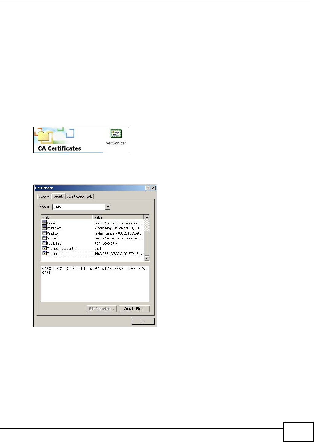
Chapter 9 System
NWA1120 Series User’s Guide 109
certification authorities. You can use the NWA to generate certification requests that contain
identifying information and public keys and then send the certification requests to a certification
authority.
9.9.5 Checking the Fingerprint of a Certificate on Your Computer
A certificate’s fingerprints are message digests calculated using the MD5 or SHA1 algorithms. The
following procedure describes how to check a certificate’s fingerprint to verify that you have the
actual certificate.
1Browse to where you have the certificate saved on your computer.
2Make sure that the certificate has a “.cer” or “.crt” file name extension.
Figure 54 Certificates on Your Computer
3Double-click the certificate’s icon to open the Certificate window. Click the Details tab and scroll
down to the Thumbprint Algorithm and Thumbprint fields.
Figure 55 Certificate Details
4Use a secure method to verify that the certificate owner has the same information in the
Thumbprint Algorithm and Thumbprint fields. The secure method may vary according to your
situation. Possible examples would be over the telephone or through an HTTPS connection.

Chapter 9 System
NWA1120 Series User’s Guide
110
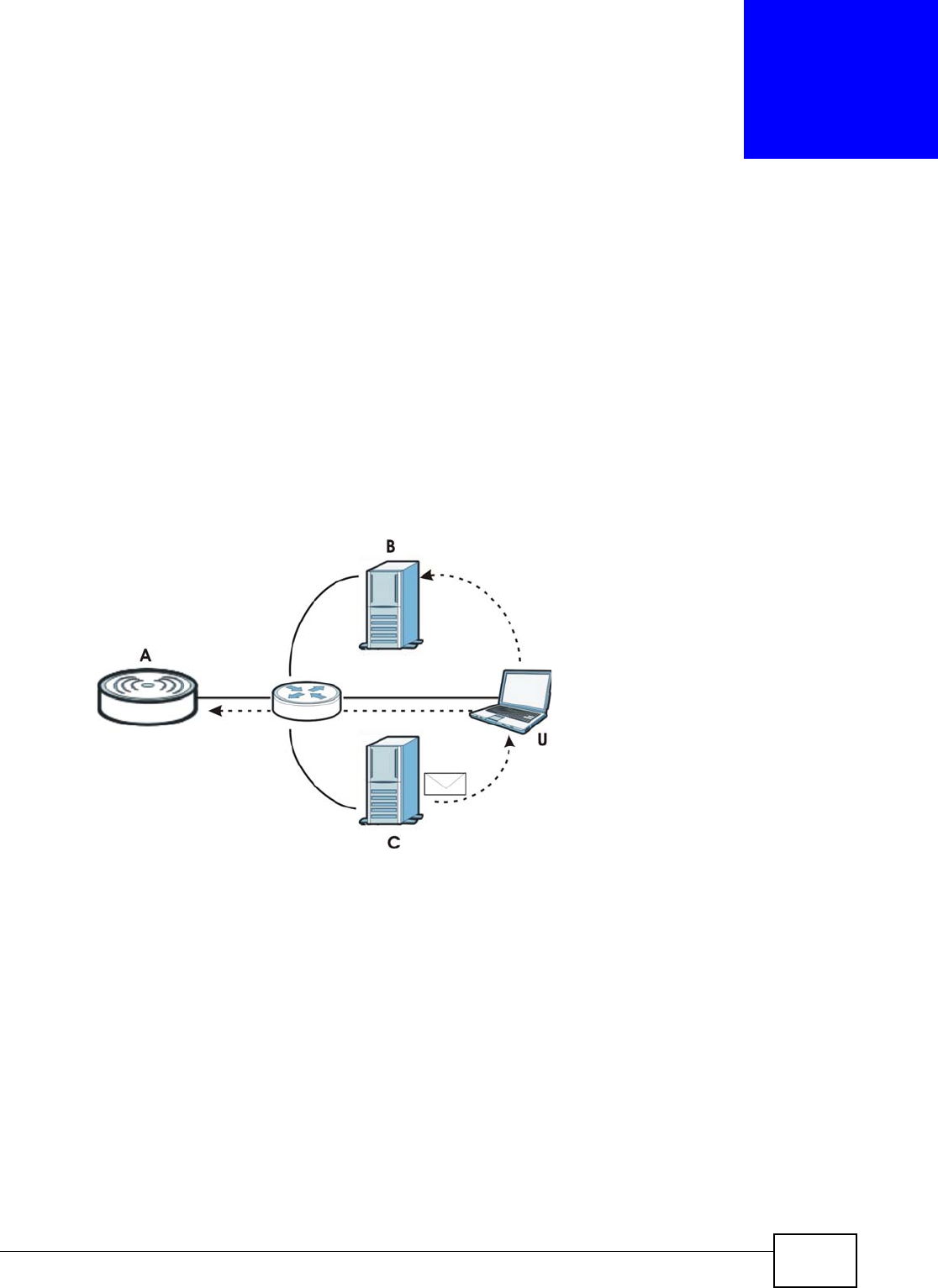
NWA1120 Series User’s Guide 111
CHAPTER 10
Log Settings
10.1 Overview
This chapter provides information on viewing and generating logs on your NWA.
Logs are files that contain recorded network activity over a set period. They are used by
administrators to monitor the health of the system(s) they are managing. Logs enable
administrators to effectively monitor events, errors, progress, etc. so that when network problems
or system failures occur, the cause or origin can be traced. Logs are also essential for auditing and
keeping track of changes made by users.
Figure 56 Accessing Logs in the Network
The figure above illustrates three ways to access logs. The user (U) can access logs directly from
the NWA (A) via the Web configurator. Logs can also be located in an external log server (B). An
email server (C) can also send harvested logs to the user’s email account.
10.2 What You Can Do in this Chapter
Use the Log Settings screen to configure where and when the NWA will send the logs, and which
logs it will send (Section 10.4 on page 112). Use the Monitor > Logs screen to display all logs or
logs for a certain category.

Chapter 10 Log Settings
NWA1120 Series User’s Guide
112
10.3 What You Need To Know
Alerts and Logs
An alert is a type of log that warrants more serious attention. Some categories such as System
Error consist of both logs and alerts. You can differentiate them by their color in the Monitor >
Logs screen. Alerts are displayed in red and logs are displayed in black.
Receiving Logs via E-mail
If you want to receive logs in your e-mail account, you need to have the necessary details ready,
such as the Server Name or Simple Mail Transfer Protocol (SMTP) Address of your e-mail account.
Ensure that you have a valid e-mail address.
Enabling Syslog Logging
To enable Syslog Logging, obtain your Syslog server’s IP address (or server name).
10.4 Log Settings Screen
Use this screen to configure to where and when the NWA is to send the logs and which logs and/or
immediate alerts it is to send.
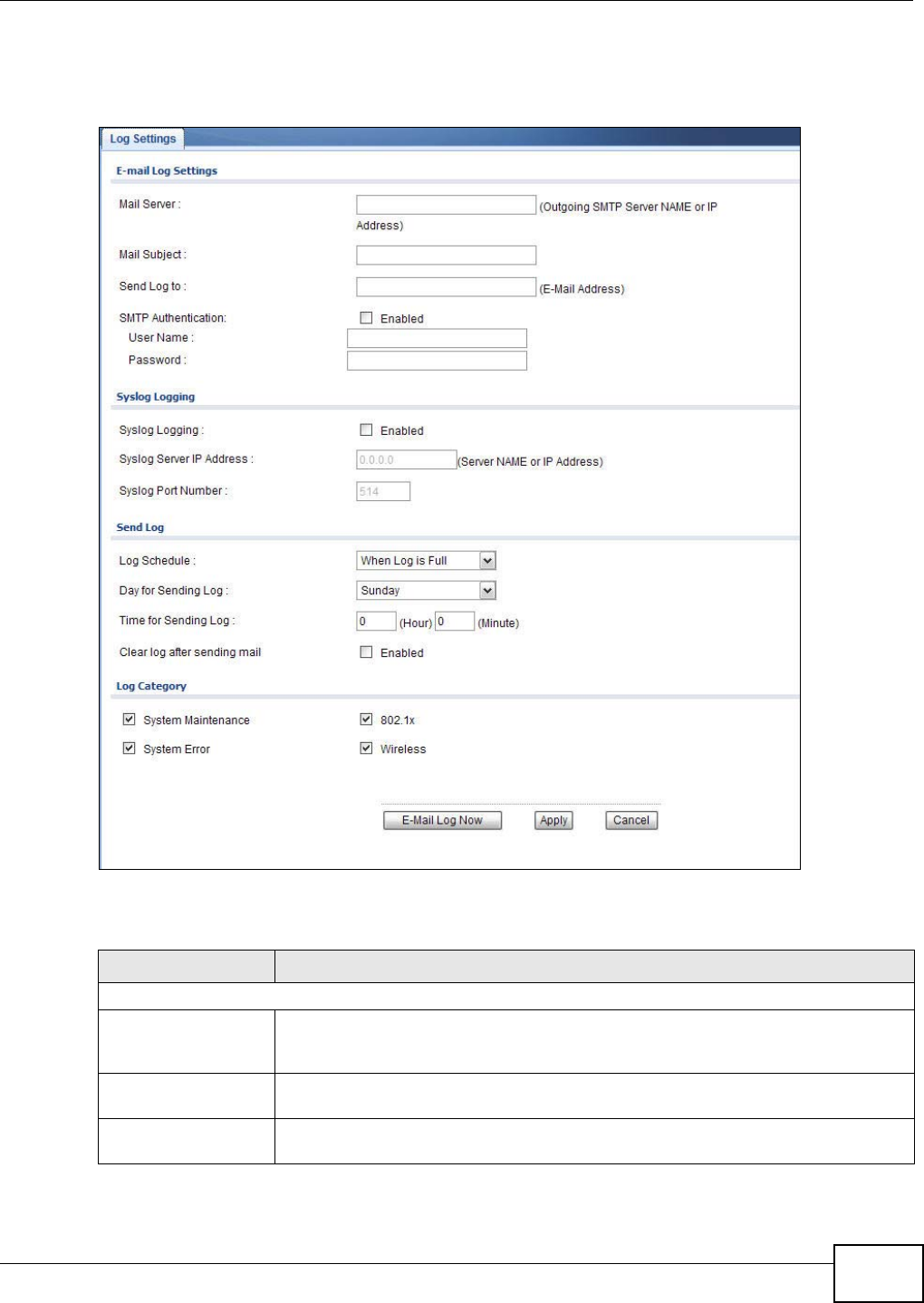
Chapter 10 Log Settings
NWA1120 Series User’s Guide 113
To change your NWA’s log settings, click Configuration > Log Settings. The screen appears as
shown.
Figure 57 Log Settings
The following table describes the labels in this screen.
Table 33 Log Settings
LABEL DESCRIPTION
E-mail Log Settings
Mail Server Enter the server name or the IP address of the mail server for the e-mail addresses
specified below. If this field is left blank, logs and alert messages will not be sent via
e-mail.
Mail Subject Type a title that you want to be in the subject line of the log e-mail message that the
NWA sends.
Send Log to Logs are sent to the e-mail address specified in this field. If this field is left blank, logs
will not be sent via e-mail.

Chapter 10 Log Settings
NWA1120 Series User’s Guide
114
SMTP Authentication SMTP (Simple Mail Transfer Protocol) is the message-exchange standard for the
Internet. Select the check box to activate SMTP authentication. If mail server
authentication is needed but this feature is disabled, you will not receive the e-mail
logs.
If you use SMTP authentication, the mail receiver should be the owner of the SMTP
account.
User Name If your e-mail account requires SMTP authentication, enter the username here.
Password Enter the password associated with the above username.
Syslog Logging Syslog logging sends a log to an external syslog server used to store logs.
Syslog Logging Select the check box to enable syslog logging.
Syslog Server IP
Address Enter the IP address of the syslog server that will log the selected categories of logs.
Syslog Port
Number Enter the port number of the syslog server that will log the selected categories of
logs.
Send Log
Log Schedule This drop-down menu is used to configure the frequency of log messages being sent
as E-mail:
• When Log is Full
•Hourly
•Daily
• Weekly
•None.
If the Weekly or the Daily option is selected, specify a time of day when the E-mail
should be sent. If the Weekly option is selected, then also specify which day of the
week the E-mail should be sent. If the When Log is Full option is selected, an alert
is sent when the log fills up. If you select None, no log messages are sent.
Day for Sending
Log This field is only available when you select Weekly in the Log Schedule field.
Use the drop down list box to select which day of the week to send the logs.
Time for Sending
Log Enter the time of the day in 24-hour format (for example 23:00 equals 11:00 pm) to
send the logs.
Clear log after
sending mail Select the check box to clear all logs after logs and alert messages are sent via e-
mail.
Log Category
System
Maintenance Click this to receive logs related to system maintenance.
System Error Click this to receive logs related to system errors.
802.1x Click this to receive logs related to the 802.1x mode.
Wireless Click this to receive logs related to the wireless function.
Email Log Now Select the categories of alerts for which you want the NWA to immediately send e-
mail alerts.
Apply Click Apply to save your customized settings.
Cancel Click Cancel to begin configuring this screen afresh.
Table 33 Log Settings (continued)
LABEL DESCRIPTION
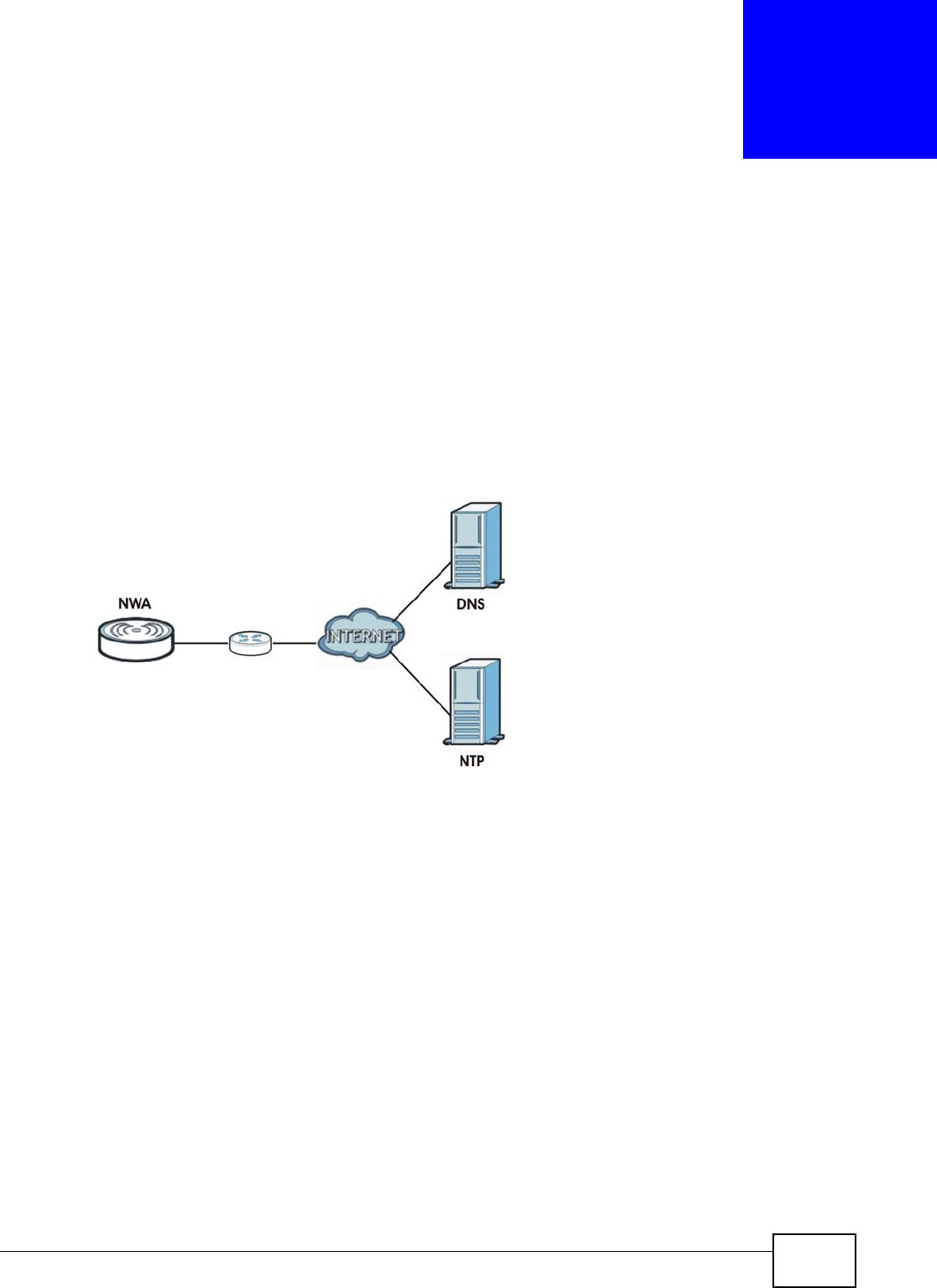
NWA1120 Series User’s Guide 115
CHAPTER 11
Maintenance
11.1 Overview
This chapter describes the maintenance screens. It discusses how you can upload new firmware,
manage configuration and restart your NWA without turning it off and on.
This chapter provides information and instructions on how to identify and manage your NWA over
the network.
Figure 58 NWA Setup
In the figure above, the NWA connects to a Domain Name Server (DNS) server to avail of a domain
name. It also connects to an Network Time Protocol (NTP) server to set the time on the device.
11.2 What You Can Do in this Chapter
•Use the General screen to specify the system name (see Section 11.4 on page 116).
•Use the Password screen to manage the password for your NWA (see Section 11.5 on page
117).
•Use the Time screen to change your NWA’s time and date. This screen allows you to configure
the NWA’s time based on your local time zone (see Section 11.6 on page 118).
•Use the Firmware Upgrade screen to upload the latest firmware for your NWA (see Section
11.7 on page 119).
•Use the Configuration File screen to view information related to factory defaults, backup
configuration, and restoring configuration (see Section 11.8 on page 120).
•Use the Restart screen to reboot the NWA without turning the power off (see Section 11.9 on
page 121).
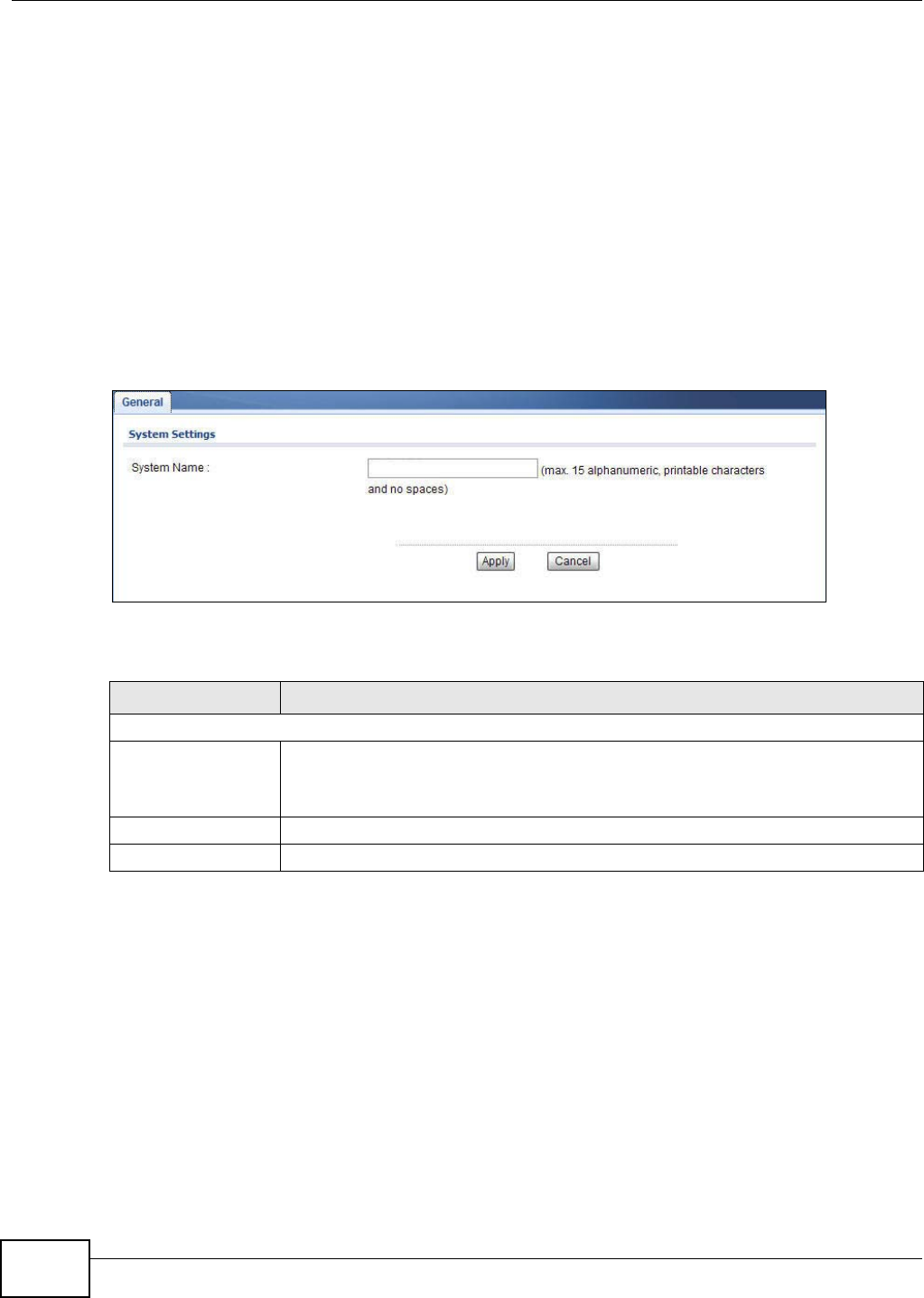
Chapter 11 Maintenance
NWA1120 Series User’s Guide
116
11.3 What You Need To Know
You can find the firmware for your device at www.zyxel.com. It is a file that uses the system project
code with a "*.bin" extension, for example "V100AAEO0.bin". The upload process uses HTTP
(Hypertext Transfer Protocol) and may take up to two minutes. After a successful upload, the
system will reboot.
11.4 General Screen
Use the General screen to identify your NWA over the network. Click Maintenance > General.
The following screen displays.
Figure 59 Maintenance > General
The following table describes the labels in this screen.
Table 34 Maintenance > General
LABEL DESCRIPTION
System Settings
System Name Type a descriptive name to identify the NWA in the Ethernet network.
This name can be up to 15 alphanumeric characters long. Spaces are not allowed, but
dashes "-" are accepted.
Apply Click Apply to save your changes.
Cancel Click Cancel to reload the previous configuration for this screen.
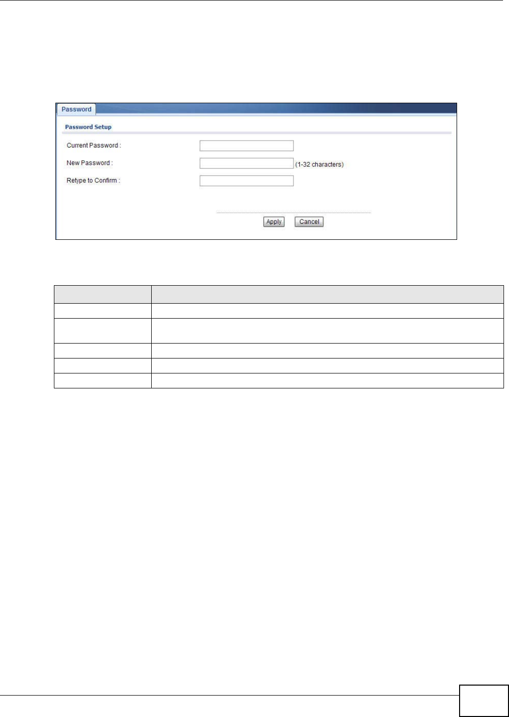
Chapter 11 Maintenance
NWA1120 Series User’s Guide 117
11.5 Password Screen
Use this screen to control access to your NWA by assigning a password to it. Click Maintenance >
Password. The following screen displays.
Figure 60 Maintenance > Password
The following table describes the labels in this screen.
Table 35 Maintenance > Password
LABEL DESCRIPTIONS
Current Password Type in your existing system password.
New Password Type your new system password. Note that as you type a password, the screen
displays a dot (.) for each character you type.
Retype to Confirm Retype your new system password for confirmation.
Apply Click Apply to save your changes.
Cancel Click Cancel to reload the previous configuration for this screen.
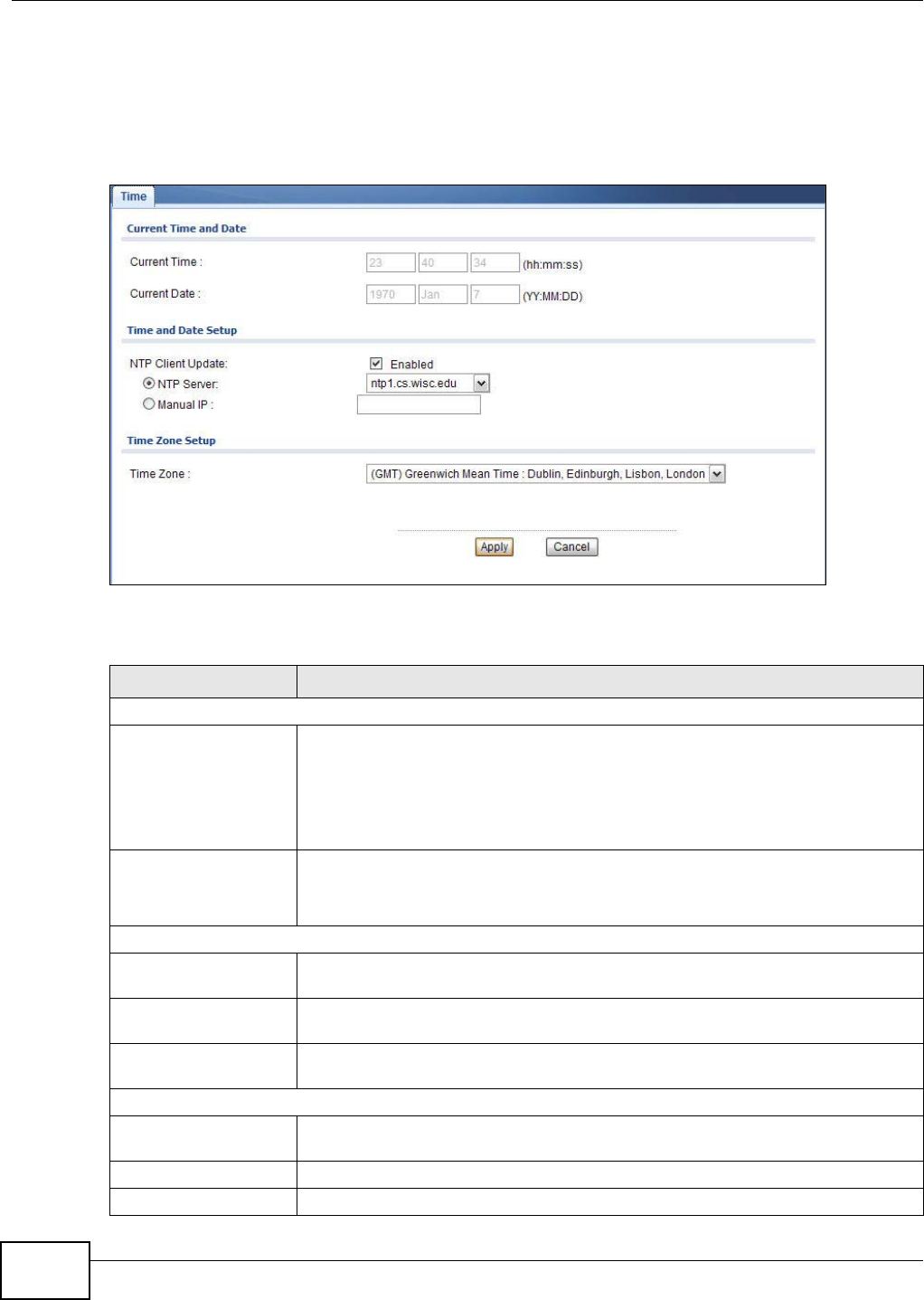
Chapter 11 Maintenance
NWA1120 Series User’s Guide
118
11.6 Time Screen
Use this screen to change your NWA’s time and date, click Maintenance > Time. The following
screen displays.
Figure 61 Maintenance > Time
The following table describes the labels in this screen.
Table 36 Maintenance > Time
LABEL DESCRIPTION
Current Time and Date
Current Time This field displays the time of your NWA.
Each time you reload this page, the NWA synchronizes the time with the time server
(if configured).
When you disable NTP Client Update, you can manually enter the new time in this
field and then click Apply.
Current Date This field displays the last updated date from the time server.
When you disable NTP Client Update, you can manually enter the new date in this
field and then click Apply.
Time and Date Setup
NTP Client Update Select this to have the NWA get the time and date from the time server you
specified below.
NTP server Select this option to use the predefined list of Network Time Protocol (NTP) servers.
Select an NTP server from the drop-list box.
Manual IP Select this option to enter the IP address or URL of your time server. Check with
your ISP/network administrator if you are unsure of this information.
Time Zone Setup
Time Zone Choose the time zone of your location. This will set the time difference between
your time zone and Greenwich Mean Time (GMT).
Apply Click Apply to save your changes.
Cancel Click Cancel to reload the previous configuration for this screen.
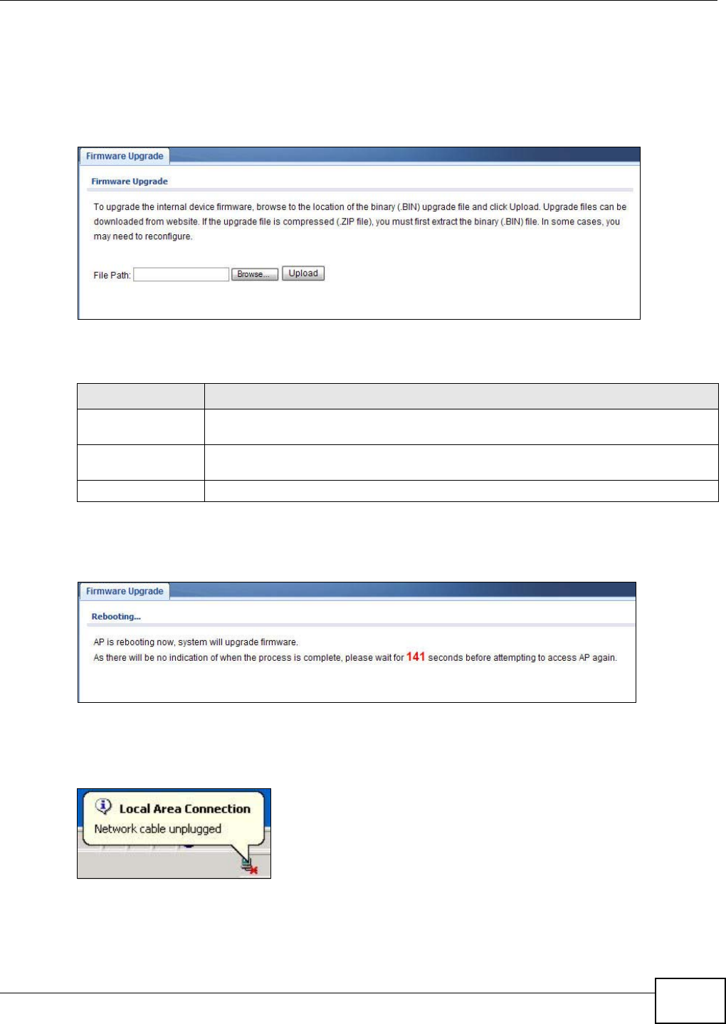
Chapter 11 Maintenance
NWA1120 Series User’s Guide 119
11.7 Firmware Upgrade Screen
Use this screen to upload a firmware to your NWA. Click Maintenance > Firmware Upgrade.
Follow the instructions in this section to upload firmware to your NWA.
Figure 62 Maintenance > Firmware Upgrade
The following table describes the labels in this screen.
Do not turn off the NWA while firmware upload is in progress!
Figure 63 Firmware Upload In Process
The NWA automatically restarts in this time causing a temporary network disconnect. In some
operating systems, you may see the following icon on your desktop.
Figure 64 Network Temporarily Disconnected
After the upload was finished, log in again and check your new firmware version in the Dashboard
screen.
Table 37 Maintenance > Firmware Upgrade
LABEL DESCRIPTION
File Path Type in the location of the file you want to upload in this field or click Browse ... to find
it.
Browse... Click Browse... to find the .bin file you want to upload. Remember that you must
decompress compressed (.zip) files before you can upload them.
Upload Click Upload to begin the upload process. This process may take up to two minutes.
Chapter 11 Maintenance
NWA1120 Series User’s Guide
120
11.8 Configuration File Screen
Use this screen to backup, restore and reset the configuration of your NWA.
Click Maintenance > Configuration File. The screen appears as shown next.
Figure 65 Maintenance > Configuration File
11.8.1 Backup Configuration
Backup configuration allows you to back up (save) the NWA’s current configuration to a file on your
computer. Once your NWA is configured and functioning properly, it is highly recommended that
you back up your configuration file before making configuration changes. The backup configuration
file will be useful in case you need to return to your previous settings.
Click Backup to save the NWA’s current configuration to your computer.
11.8.2 Restore Configuration
Restore configuration allows you to upload a new or previously saved configuration file from your
computer to your NWA.
Do not turn off the NWA while configuration file upload is in progress.
You must then wait one minute before logging into the NWA again.
Table 38 Restore Configuration
LABEL DESCRIPTION
File Path Type in the location of the file you want to upload in this field or click Browse ... to find
it.
Browse... Click Browse... to find the file you want to upload. Remember that you must
decompress compressed (.ZIP) files before you can upload them.
Upload Click Upload to begin the upload process.
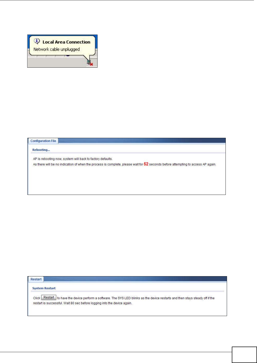
Chapter 11 Maintenance
NWA1120 Series User’s Guide 121
The NWA automatically restarts in this time causing a temporary network disconnect. In some
operating systems, you may see the following icon on your desktop.
Figure 66 Network Temporarily Disconnected
If you uploaded the default configuration file you may need to change the IP address of your
computer to be in the same subnet as that of the default NWA IP address (192.168.1.2). See
Appendix A on page 129 for details on how to set up your computer’s IP address.
11.8.3 Back to Factory Defaults
Pressing the Reset button in this section clears all user-entered configuration information and
returns the NWA to its factory defaults as shown on the screen. The following screen will appear.
Figure 67 Reset Message
You can also press the RESET button to reset your NWA to its factory default settings. Refer to
Section 2.3 on page 21 for more information.
11.9 Restart Screen
Use this screen to reboot the NWA without turning the power off.
Click Maintenance > Restart. The following screen displays.
Figure 68 Maintenance > Restart
Click Restart to have the NWA reboot. This does not affect the NWA's configuration.

Chapter 11 Maintenance
NWA1120 Series User’s Guide
122

NWA1120 Series User’s Guide 123
CHAPTER 12
Troubleshooting
This chapter offers some suggestions to solve problems you might encounter. The potential
problems are divided into the following categories.
•Power, Hardware Connections, and LEDs
•NWA Access and Login
•Internet Access
•Wireless LAN
12.1 Power, Hardware Connections, and LEDs
The NWA does not turn on. None of the LEDs turn on.
1Make sure you are using the power adaptor or cord included with the NWA.
2Make sure the power adaptor or cord is connected to the NWA and plugged in to an appropriate
power source. Make sure the power source is turned on.
3Disconnect and re-connect the power adaptor or cord to the NWA.
4If the problem continues, contact the vendor.
One of the LEDs does not behave as expected.
1Make sure you understand the normal behavior of the LED. See Section 1.7 on page 18.
2Check the hardware connections. See the Quick Start Guide.
3Inspect your cables for damage. Contact the vendor to replace any damaged cables.
4Disconnect and re-connect the power adaptor to the NWA.
5If the problem continues, contact the vendor.

Chapter 12 Troubleshooting
NWA1120 Series User’s Guide
124
12.2 NWA Access and Login
I forgot the IP address for the NWA.
1The default IP address is 192.168.1.2.
2If the NWA is working as a DHCP client and receives an IP address from a DHCP server, check the
DHCP server for the NWA’s IP address.
3If you configured a static IP address and have forgotten it, you have to reset the device to its
factory defaults. See Section 2.3 on page 21.
I forgot the password.
1The default password is 1234.
2If this does not work, you have to reset the device to its factory defaults. See Section 2.3 on page
21.
I cannot see or access the Login screen in the web configurator.
1Make sure you are using the correct IP address.
• The default IP address is 192.168.1.2.
• If you changed the IP address (Section 7.4 on page 93), use the new IP address.
• If you changed the IP address and have forgotten it, see the troubleshooting suggestions for I
forgot the IP address for the NWA.
2Check the hardware connections, and make sure the LEDs are behaving as expected. See the Quick
Start Guide and Section 1.7 on page 18.
3Make sure your Internet browser does not block pop-up windows and has JavaScript and Java
enabled. See Section 12.1 on page 123.
4Make sure your computer is in the same subnet as the NWA. (If you know that there are routers
between your computer and the NWA, skip this step.)
• If there is no DHCP server on your network, make sure your computer’s IP address is in the
same subnet as the NWA.
5Reset the device to its factory defaults, and try to access the NWA with the default IP address. See
Chapter 2 on page 21.
6If the problem continues, contact the network administrator or vendor, or try one of the advanced
suggestions.

Chapter 12 Troubleshooting
NWA1120 Series User’s Guide 125
Advanced Suggestions
• Try to access the NWA using another service, such as Telnet. If you can access the NWA, check
the remote management settings to find out why the NWA does not respond to HTTP.
• If your computer is connected wirelessly, use a computer that is connected to a LAN/Ethernet
port.
I can see the Login screen, but I cannot log in to the NWA.
1Make sure you have entered the user name and password correctly. The default user name is
admin and default password is 1234. This fields are case-sensitive, so make sure [Caps Lock] is
not on.
2Disconnect and re-connect the power adaptor or cord to the NWA.
3If this does not work, you have to reset the device to its factory defaults. See Section 2.3 on page
21.
I cannot use FTP to upload new firmware.
See the troubleshooting suggestions for I cannot see or access the Login screen in the web
configurator. Ignore the suggestions about your browser.
12.3 Internet Access
I cannot access the Internet through the NWA.
1Check the hardware connections, and make sure the LEDs are behaving as expected. See the Quick
Start Guide and Section 12.1 on page 123.
2Make sure your NWA is connected to a networking device that provides Internet access.
3Make sure your computer is set to obtain a dynamic IP address or has an IP address which is in the
same subnet as the broadband modem or router.
4If you are trying to access the Internet wirelessly, make sure the wireless settings on the wireless
client are the same as the settings on the AP.
5Disconnect all the cables from your device, and follow the directions in the Quick Start Guide again.
6If the problem continues, contact your ISP.

Chapter 12 Troubleshooting
NWA1120 Series User’s Guide
126
I cannot access the Internet anymore. I had access to the Internet (with the NWA), but my
Internet connection is not available anymore.
1Check the hardware connections, and make sure the LEDs are behaving as expected. See the Quick
Start Guide and Section 1.7 on page 18.
2Reboot the NWA.
3If the problem continues, contact your ISP or network administrator.
The Internet connection is slow or intermittent.
1There might be a lot of traffic on the network. Look at the LEDs, and check Section 1.7 on page 18.
If the NWA is sending or receiving a lot of information, try closing some programs that use the
Internet, especially peer-to-peer applications.
2Check the signal strength. If the signal is weak, try moving the NWA (in wireless client mode) closer
to the AP (if possible), and look around to see if there are any devices that might be interfering with
the wireless network (microwaves, other wireless networks, and so on).
3Reboot the NWA.
4If the problem continues, contact the network administrator or vendor, or try one of the advanced
suggestions.
Advanced Suggestions
• Check the settings for QoS. If it is disabled, you might consider activating it.
12.4 Wireless LAN
I cannot access the NWA or ping any computer from the WLAN.
1Make sure the wireless LAN is enabled on the NWA.
2Make sure the wireless adapter on the wireless station is working properly.
3Make sure the wireless adapter installed on your computer is IEEE 802.11 compatible and supports
the same wireless standard as the NWA.
4Make sure your computer (with a wireless adapter installed) is within the transmission range of the
NWA.

Chapter 12 Troubleshooting
NWA1120 Series User’s Guide 127
5Check that both the NWA and your wireless client are using the same wireless and wireless security
settings.

Chapter 12 Troubleshooting
NWA1120 Series User’s Guide
128