ZyXEL Communications NWA5301NJ 802.11 b/g/n In-wall Managed Access Point User Manual Book
ZyXEL Communications Corporation 802.11 b/g/n In-wall Managed Access Point Book
UserManual.wiki
>
ZyXEL Communications
>
NWA5301NJ User Manual
User Manual.pdf
Navigation menu
Upload a User Manual
Namespaces
Wiki Guide
HTML
PDF
Info
Views
User Manual
Discussion / Help
Navigation
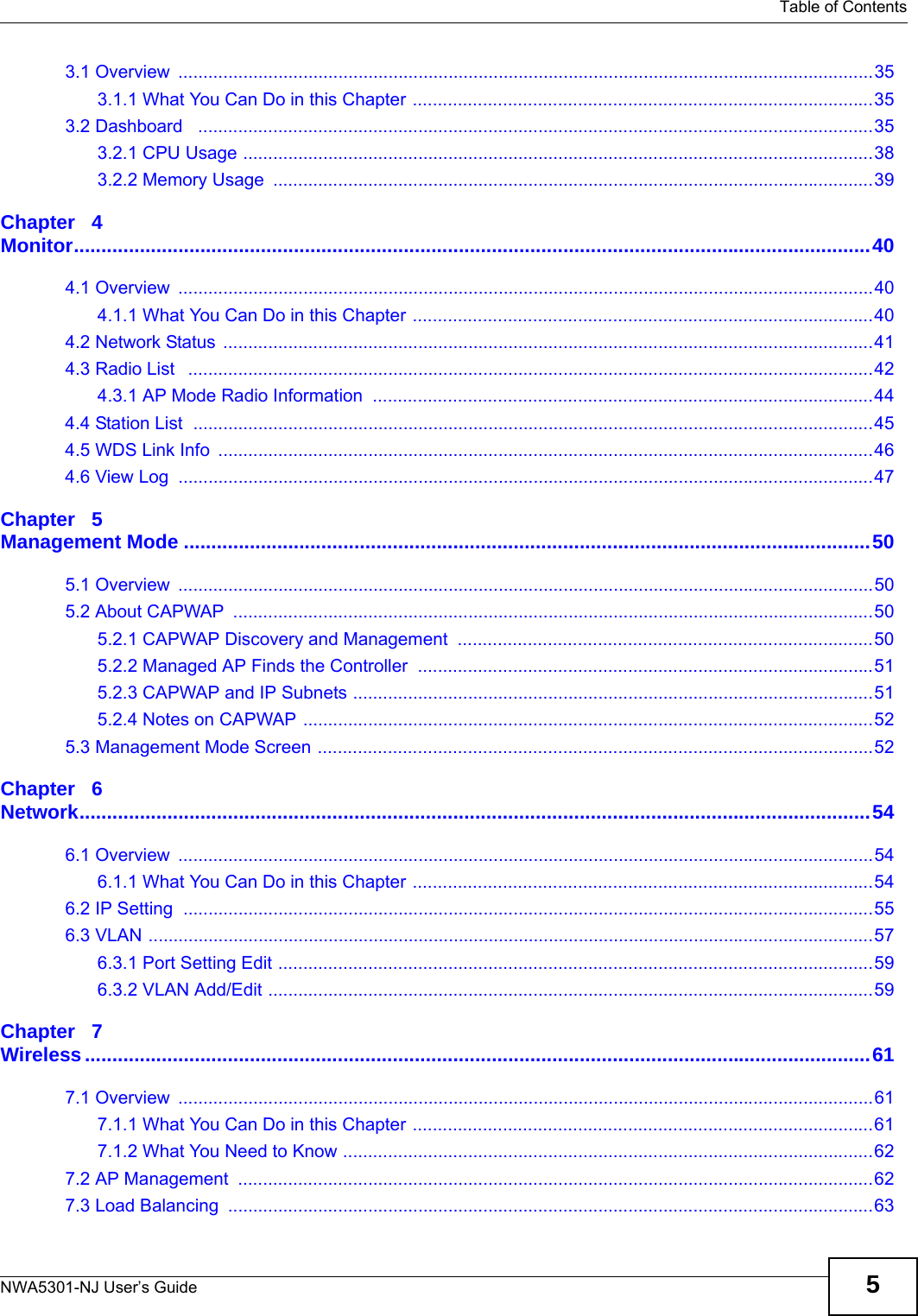


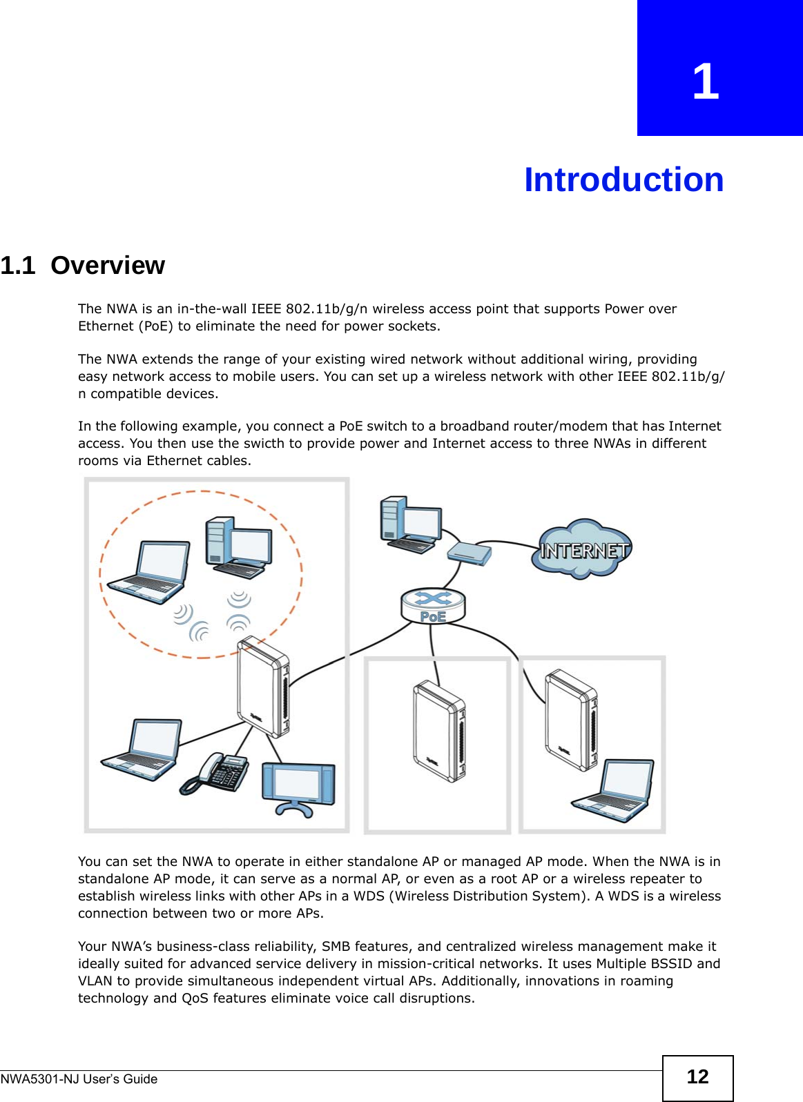
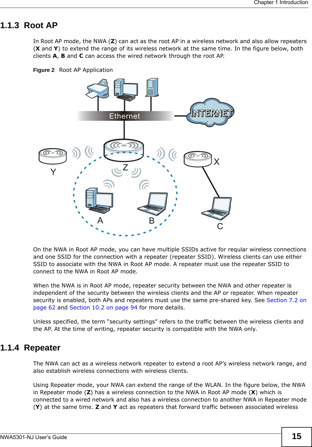
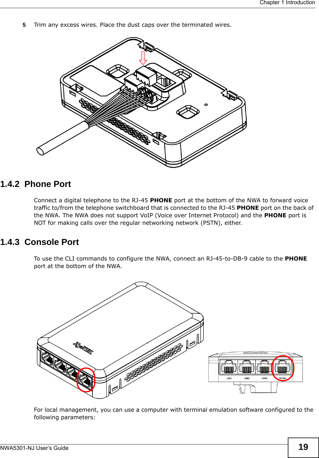
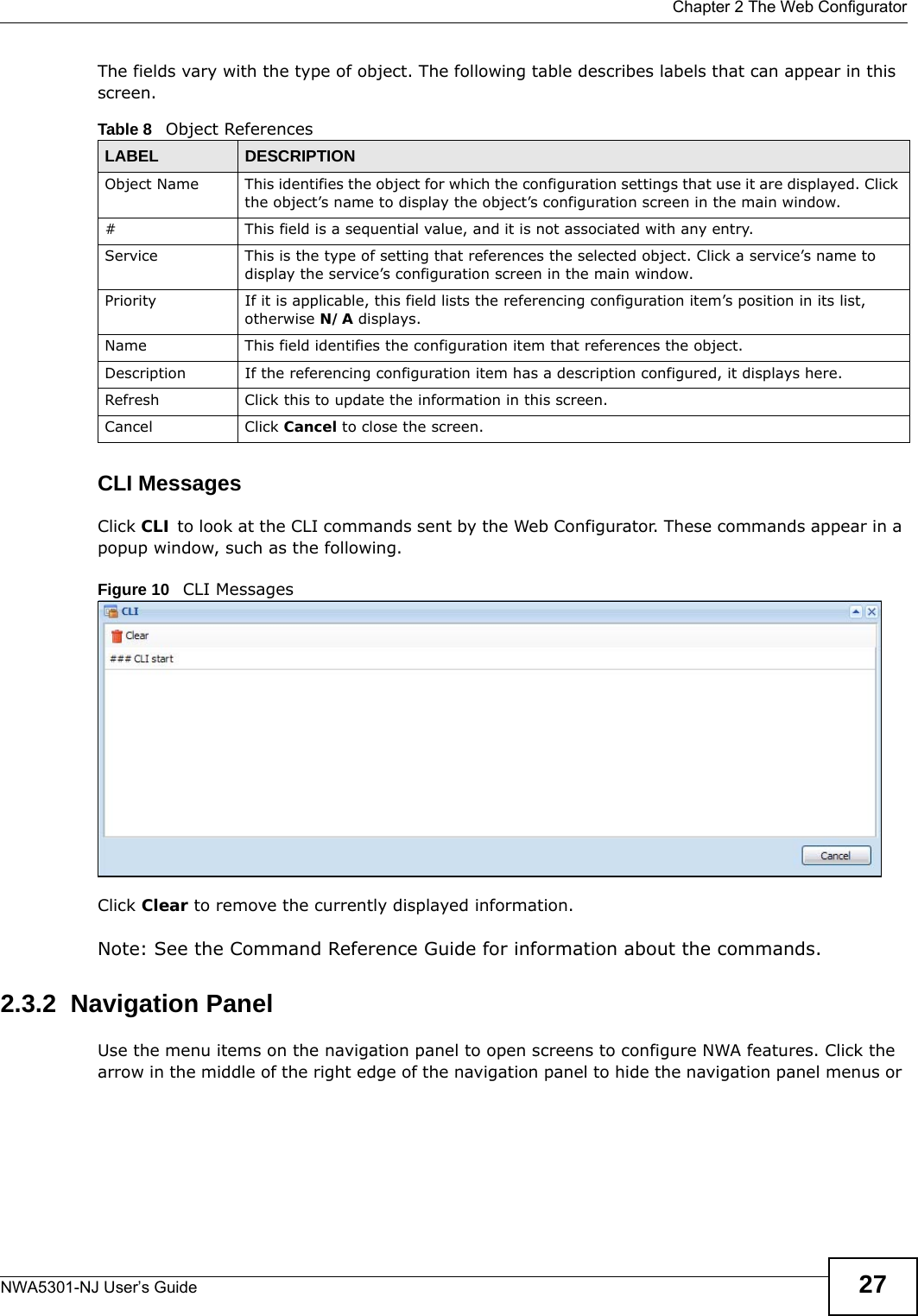
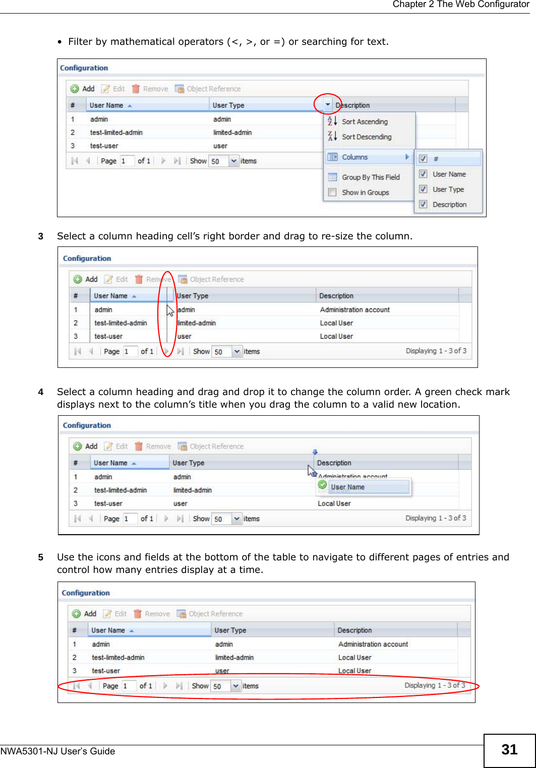
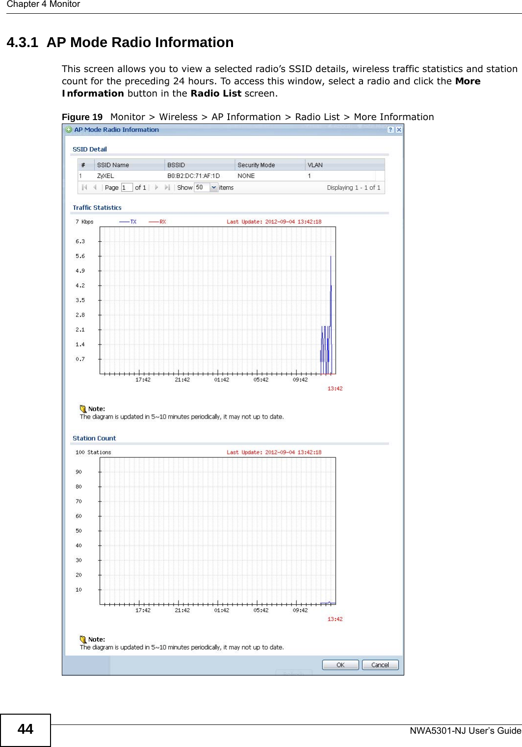
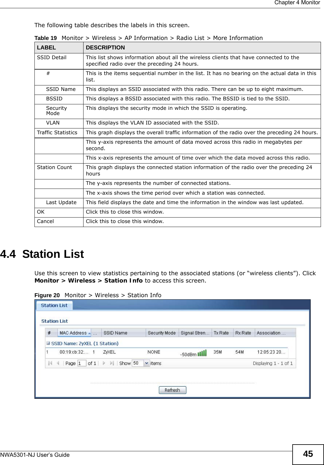
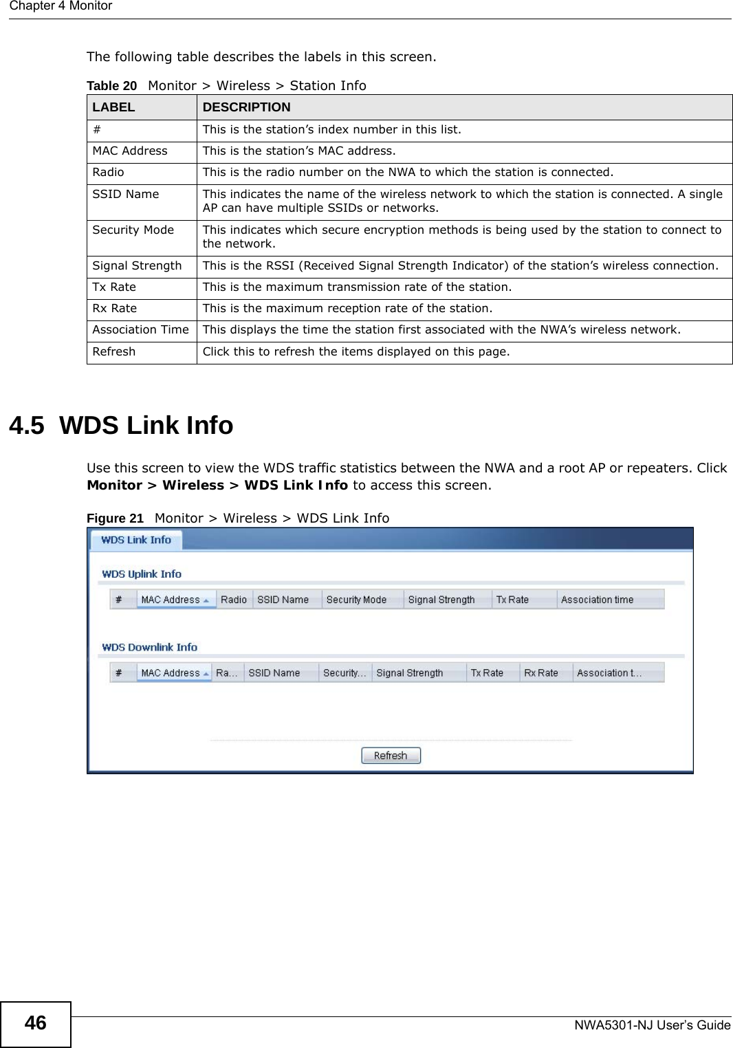
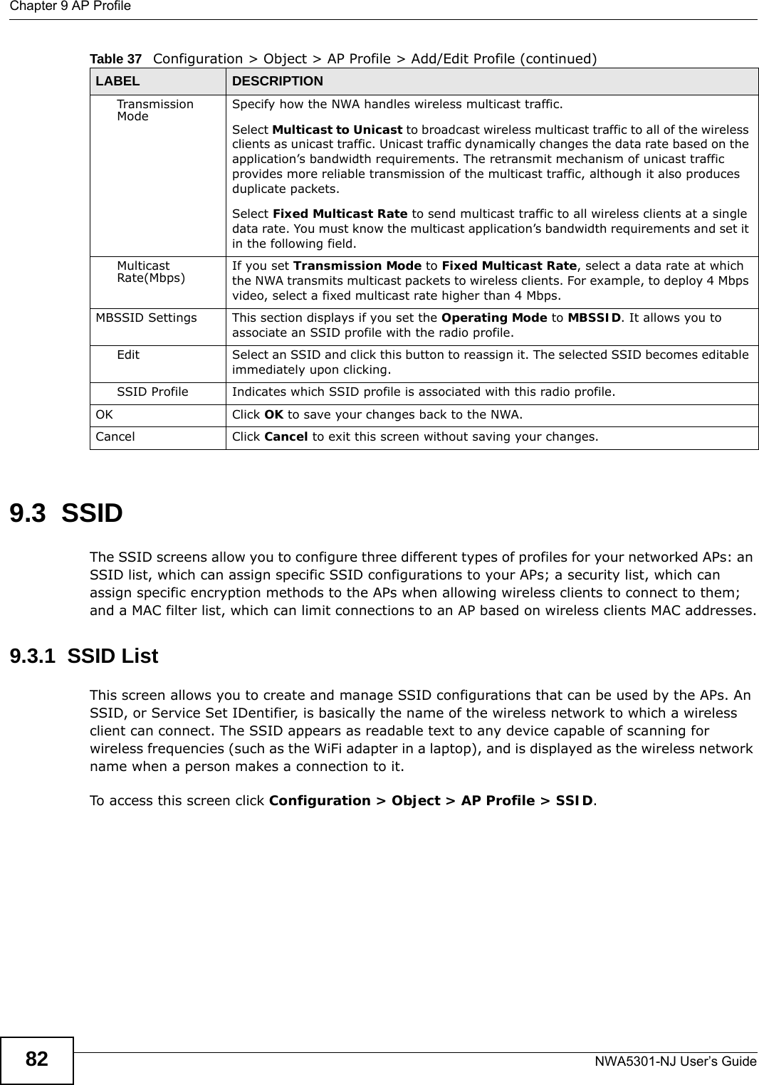
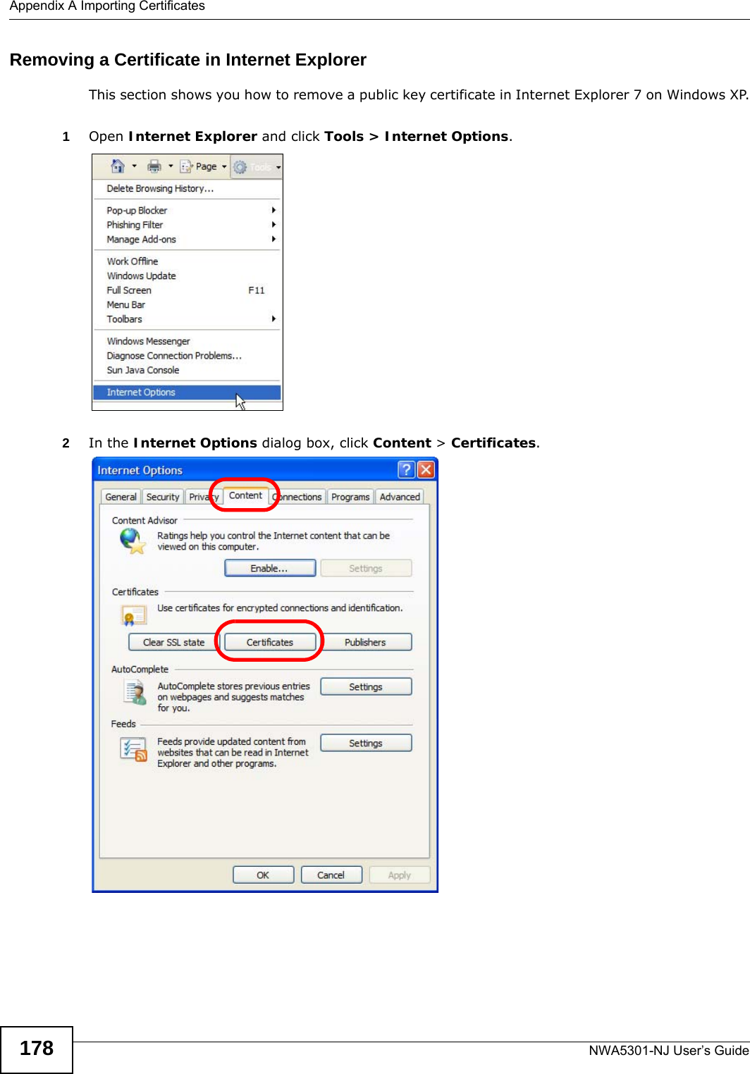
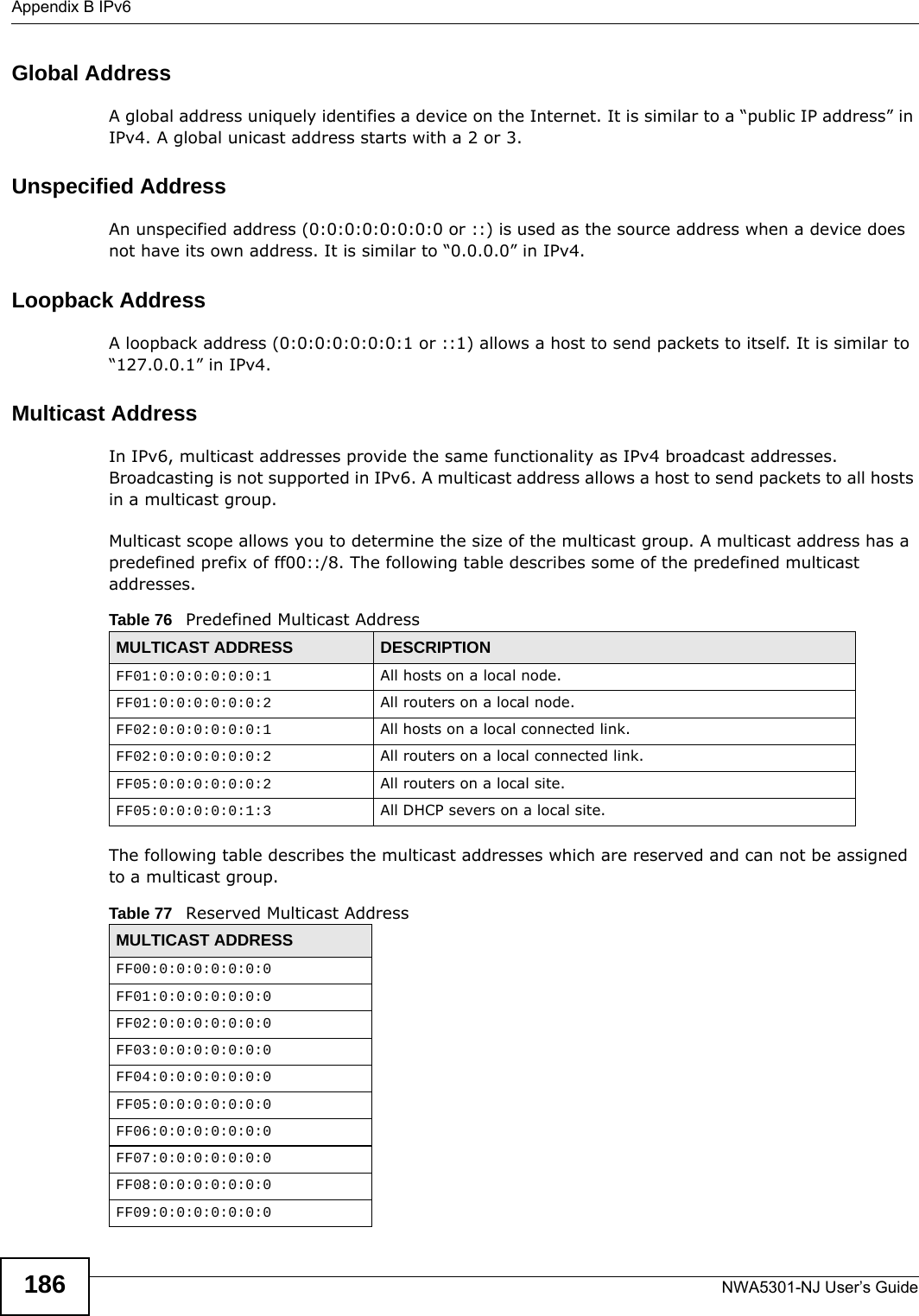
![Chapter 2 The Web ConfiguratorNWA5301-NJ User’s Guide322.3.4.2 Working with Table EntriesThe tables have icons for working with table entries. A sample is shown next. You can often use the [Shift] or [Ctrl] key to select multiple entries to remove, activate, or deactivate. Table 12 Common Table IconsHere are descriptions for the most common table icons.2.3.4.3 Working with ListsWhen a list of available entries displays next to a list of selected entries, you can often just double-click an entry to move it from one list to the other. In some lists you can also use the [Shift] or [Ctrl] key to select multiple entries, and then use the arrow button to move them to the other list. Figure 13 Working with Lists Table 13 Common Table IconsLABEL DESCRIPTIONAdd Click this to create a new entry. For features where the entry’s position in the numbered list is important (features where the NWA applies the table’s entries in order like the firewall for example), you can select an entry and click Add to create a new entry after the selected entry.Edit Double-click an entry or select it and click Edit to open a screen where you can modify the entry’s settings. In some tables you can just click a table entry and edit it directly in the table. For those types of tables small red triangles display for table entries with changes that you have not yet applied.Remove To remove an entry, select it and click Remove. The NWA confirms you want to remove it before doing so.Activate To turn on an entry, select it and click Activate.Inactivate To turn off an entry, select it and click Inactivate.Object Reference Select an entry and click Object Reference to open a screen that shows which settings use the entry.](https://usermanual.wiki/ZyXEL-Communications/NWA5301NJ/User-Guide-2154980-Page-32.png)
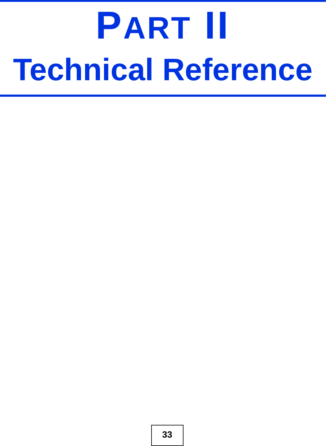
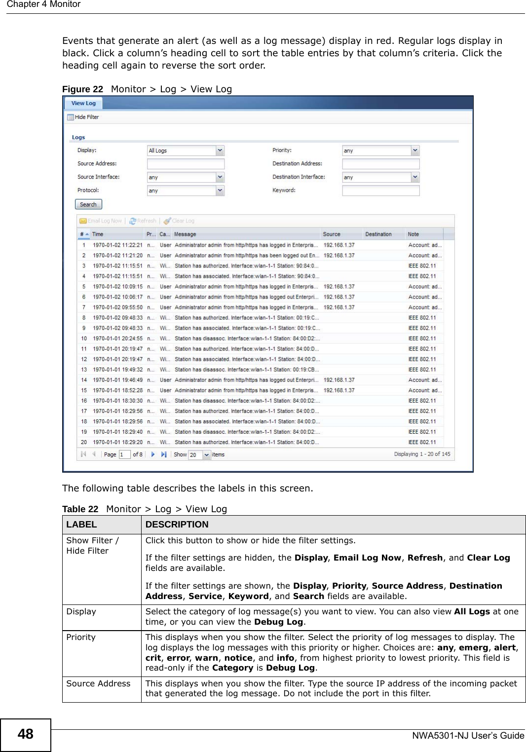
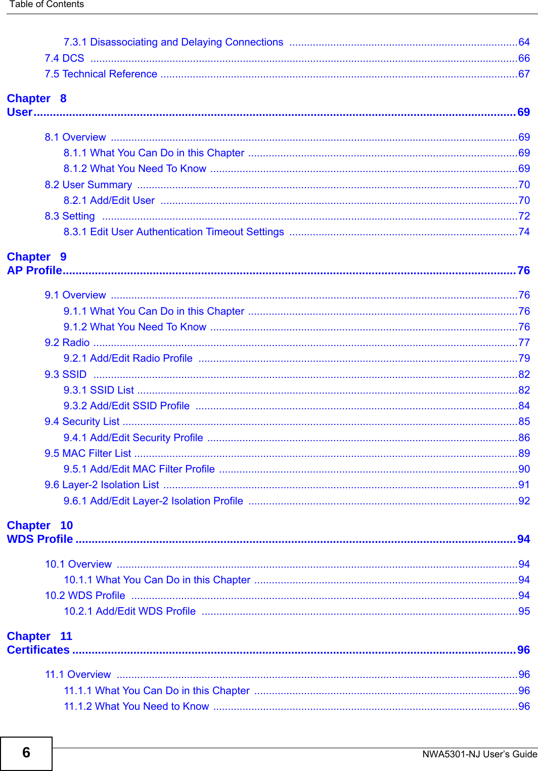
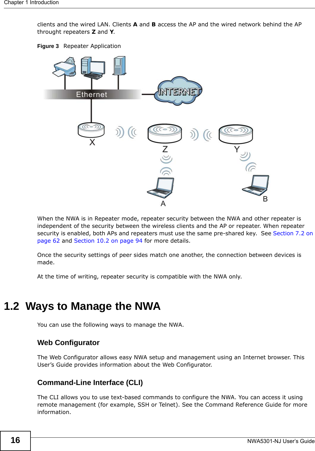
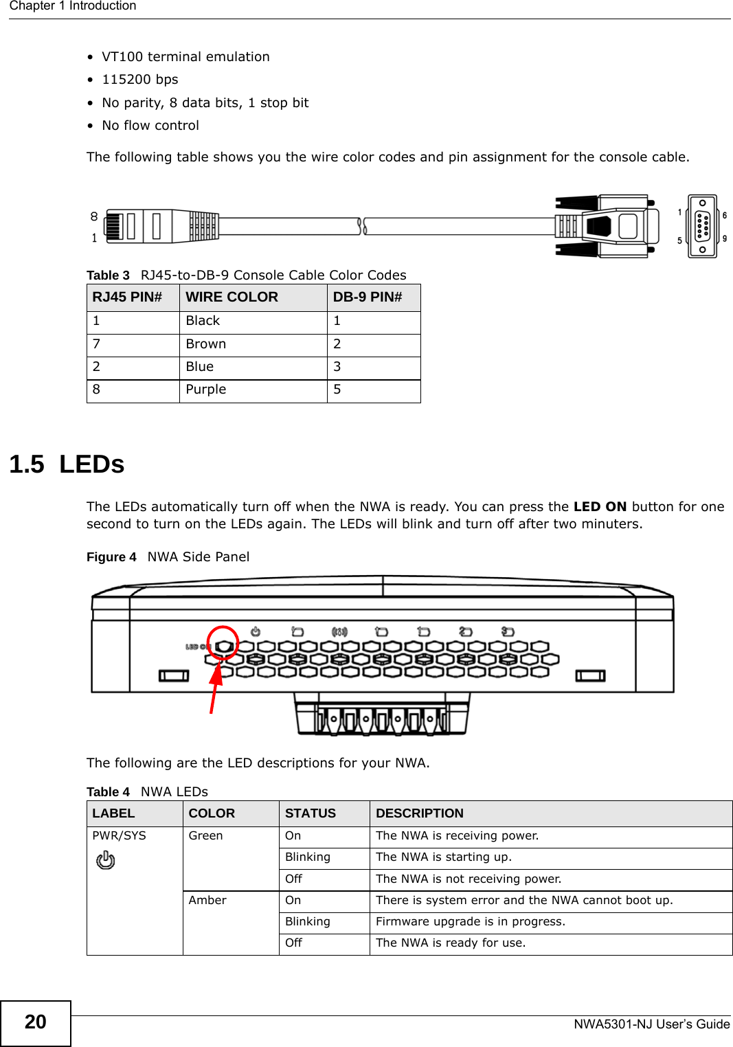
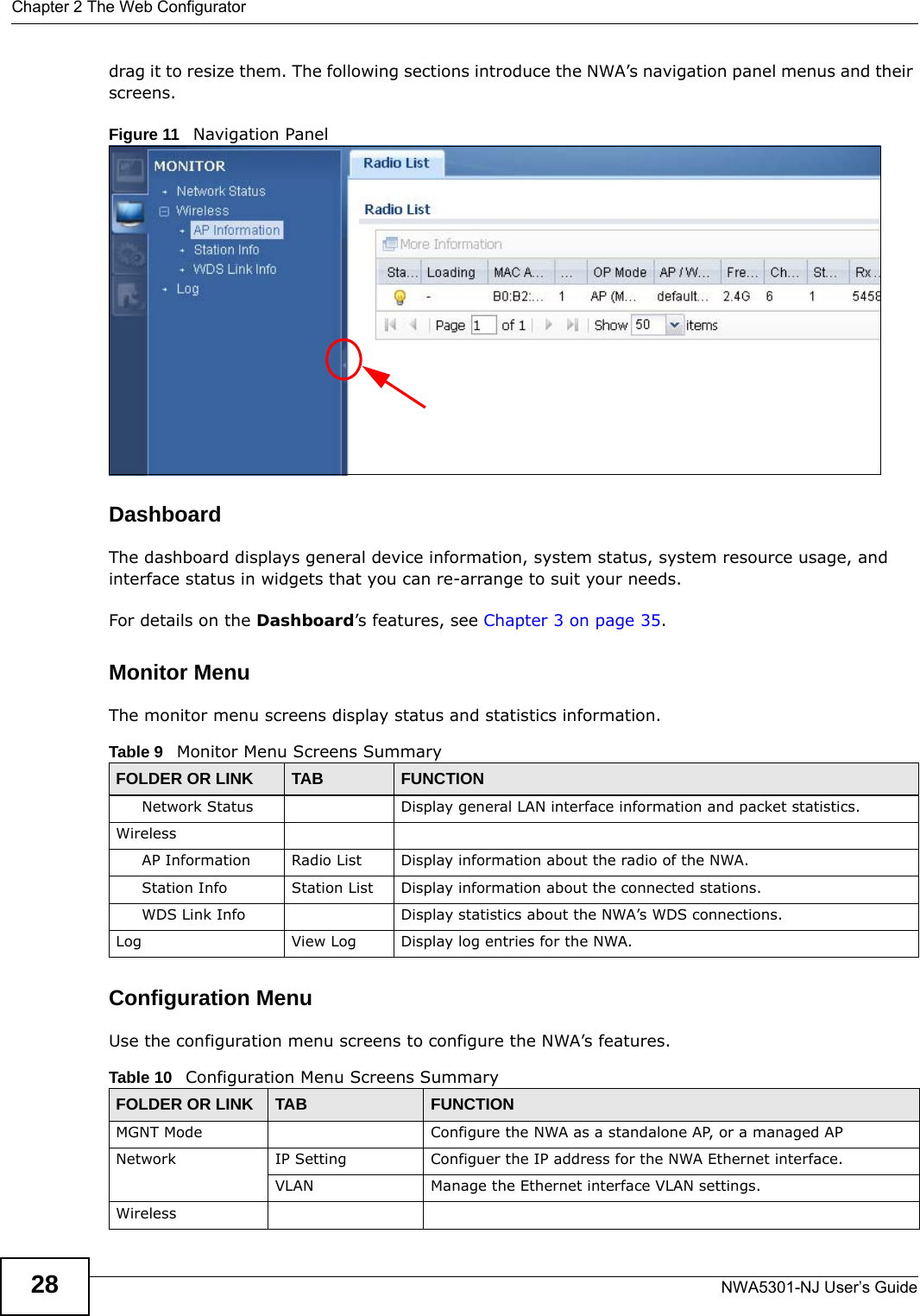
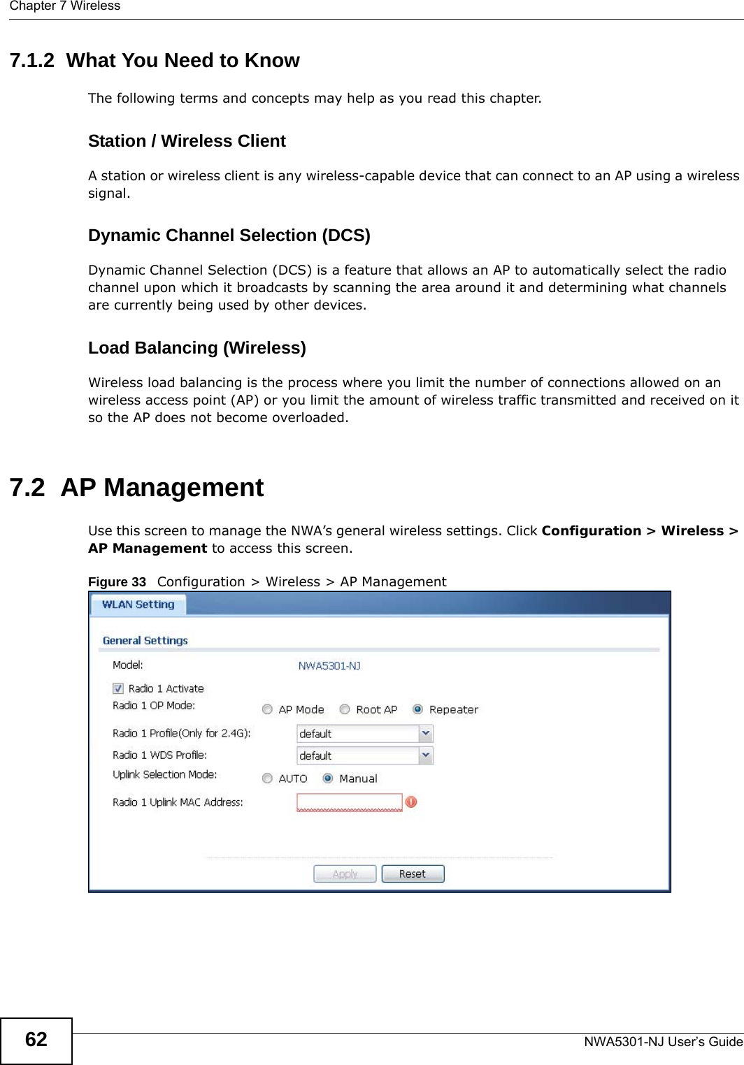
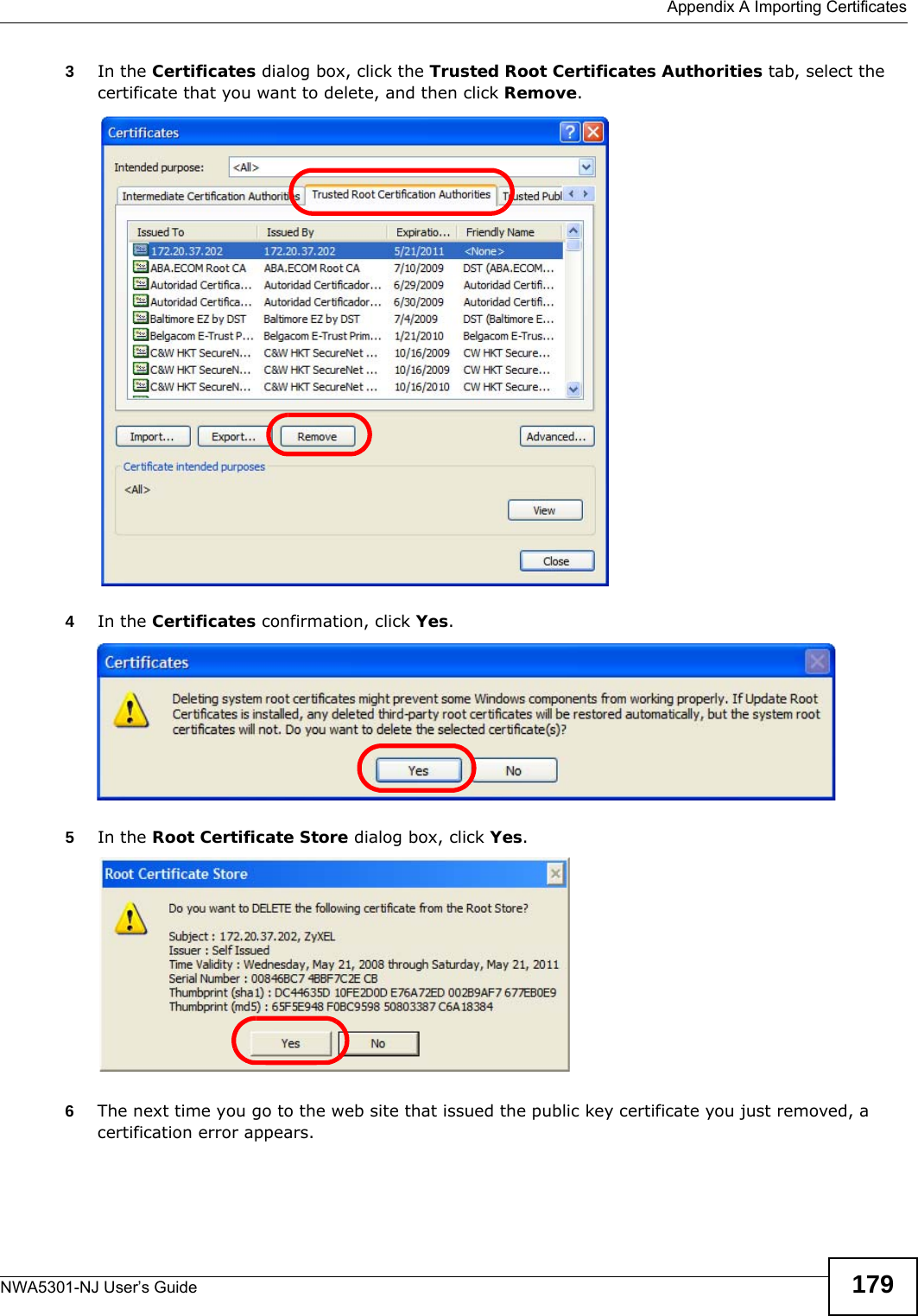
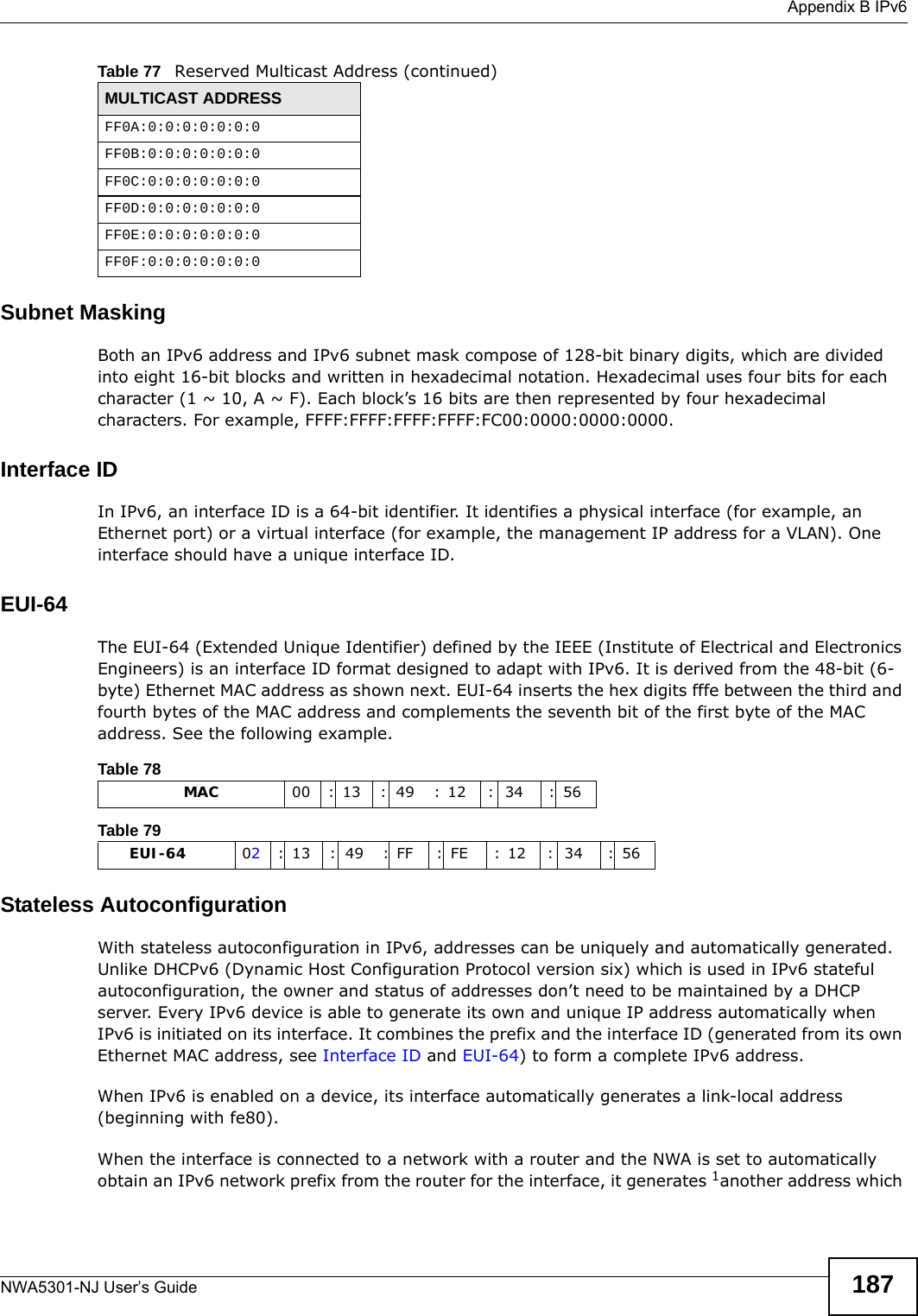
![Chapter 4 MonitorNWA5301-NJ User’s Guide 49The Web Configurator saves the filter settings if you leave the View Log screen and return to it later.Destination AddressThis displays when you show the filter. Type the IP address of the destination of the incoming packet when the log message was generated. Do not include the port in this filter.Source Interface This displays when you show the filter. Select the source interface of the packet that generated the log message. Destination InterfaceThis displays when you show the filter. Select the destination interface of the packet that generated the log message. Protocol This displays when you show the filter. Select a service protocol whose log messages you would like to see. Keyword This displays when you show the filter. Type a keyword to look for in the Message, Source, Destination and Note fields. If a match is found in any field, the log message is displayed. You can use up to 63 alphanumeric characters and the underscore, as well as punctuation marks ()’ ,:;?! +-*/= #$% @ ; the period, double quotes, and brackets are not allowed.Search This displays when you show the filter. Click this button to update the log using the current filter settings.Email Log Now Click this button to send log messages to the Active e-mail addresses specified in the Send Log To field on the Configuration > Log & Report > Log Settings screen.Refresh Click this to update the list of logs.Clear Log Click this button to clear the whole log, regardless of what is currently displayed on the screen.#This field is a sequential value, and it is not associated with a specific log message.Time This field displays the time the log message was recorded.Priority This field displays the priority of the log message. It has the same range of values as the Priority field above.Category This field displays the log that generated the log message. It is the same value used in the Display and (other) Category fields.Message This field displays the reason the log message was generated. The text “[count=x]”, where x is a number, appears at the end of the Message field if log consolidation is turned on and multiple entries were aggregated to generate into this one.Source This field displays the source IP address and the port number in the event that generated the log message.Destination This field displays the destination IP address and the port number of the event that generated the log message.Note This field displays any additional information about the log message.Table 22 Monitor > Log > View Log (continued)LABEL DESCRIPTION](https://usermanual.wiki/ZyXEL-Communications/NWA5301NJ/User-Guide-2154980-Page-49.png)
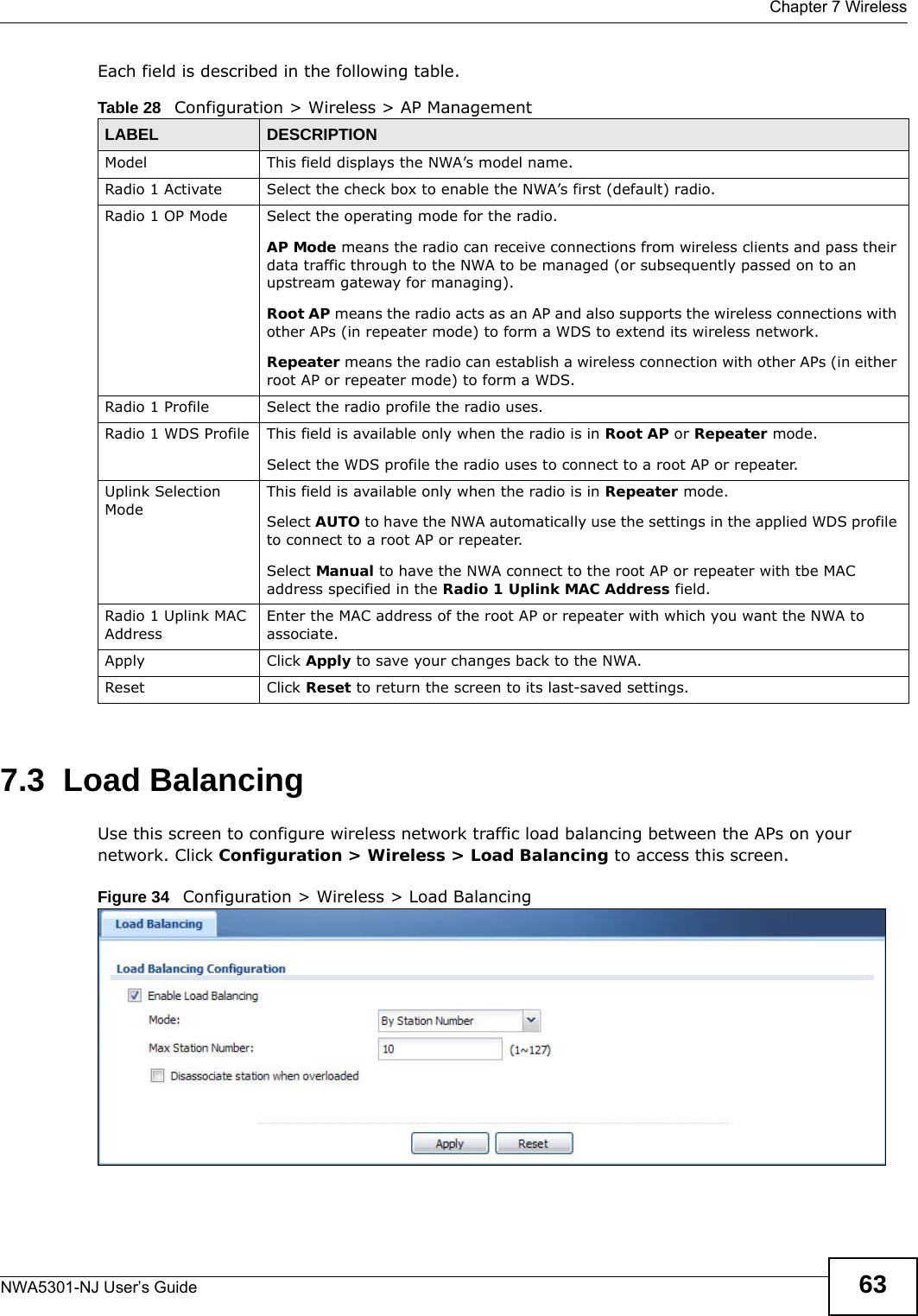
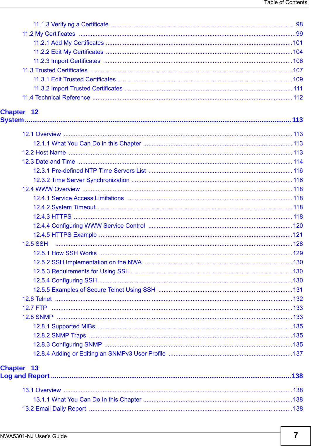
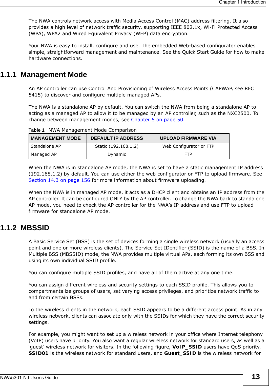
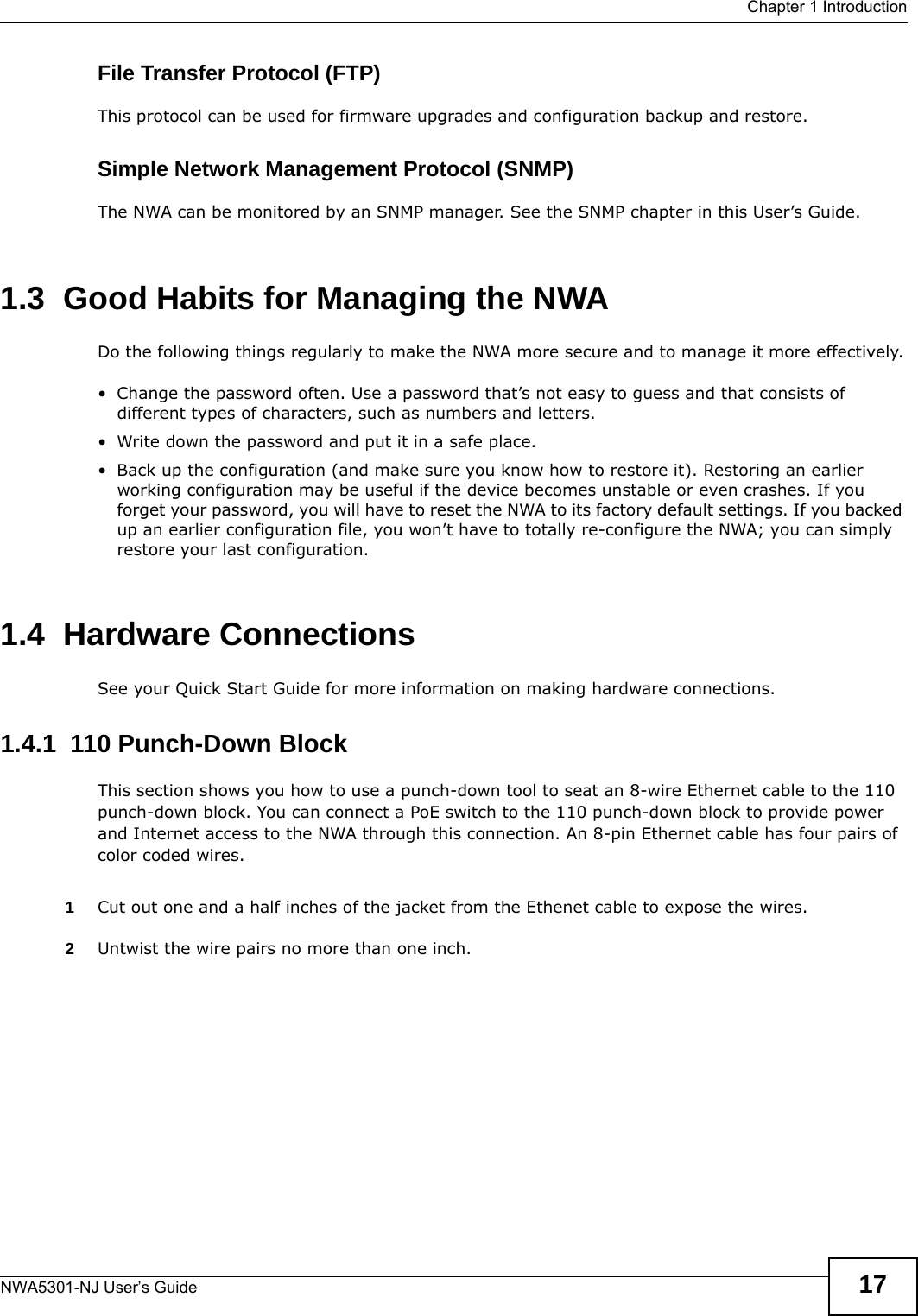
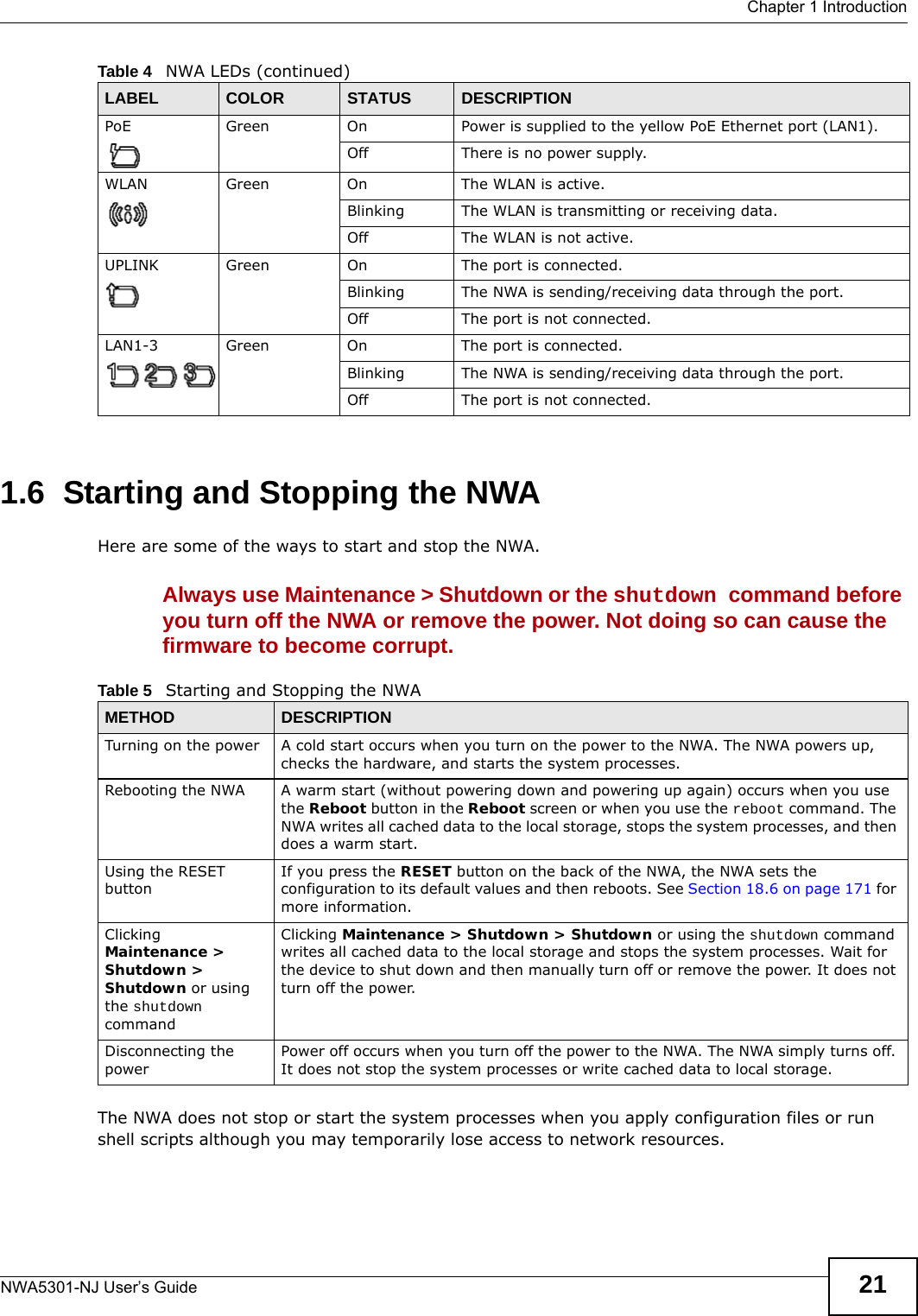
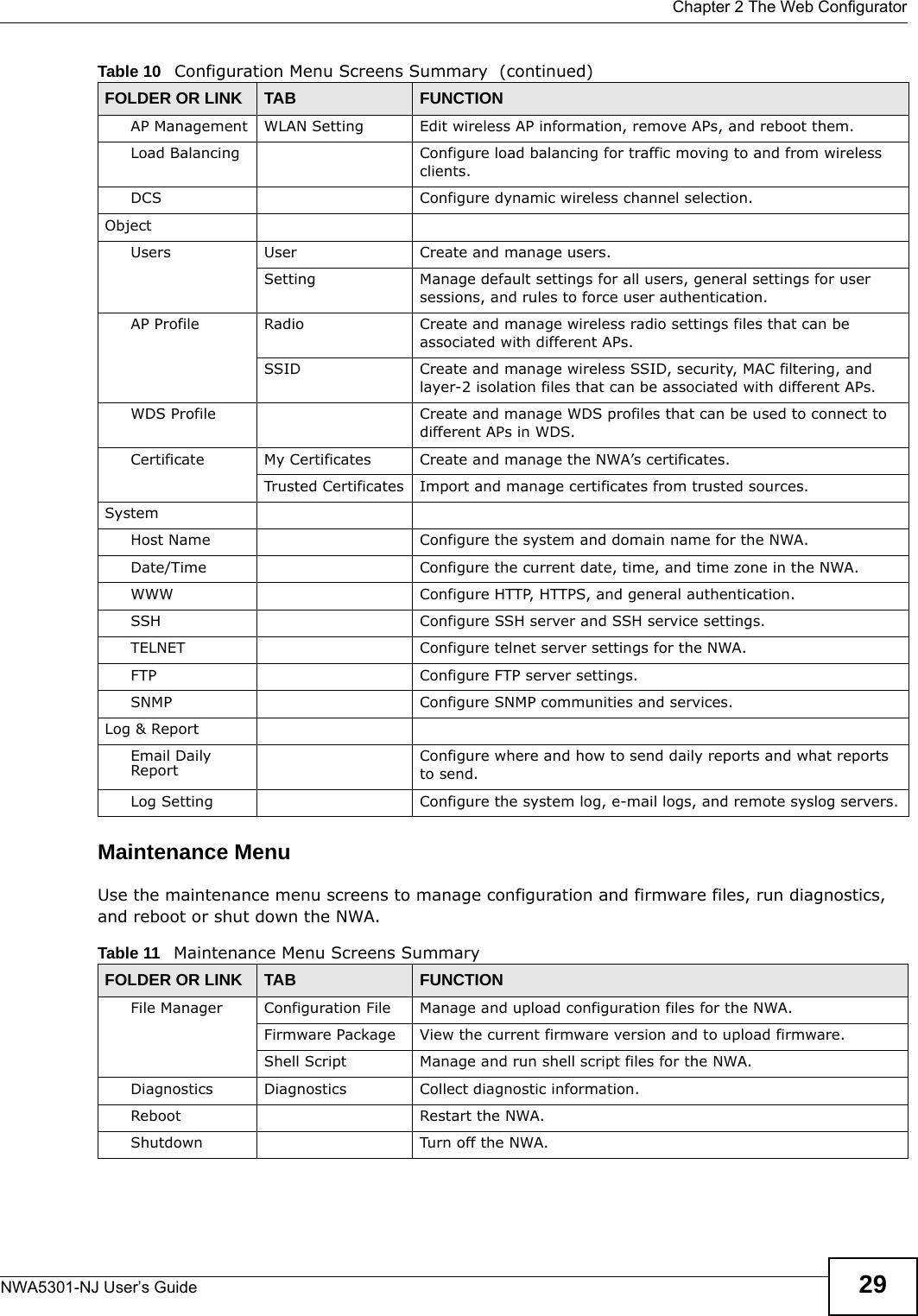
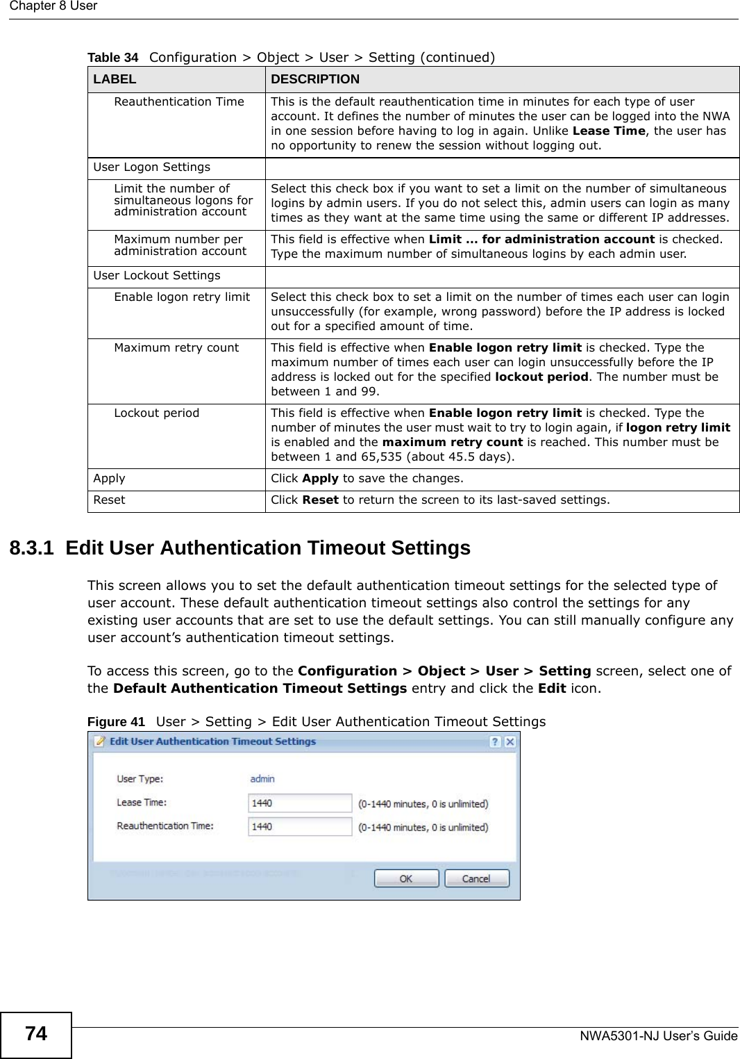
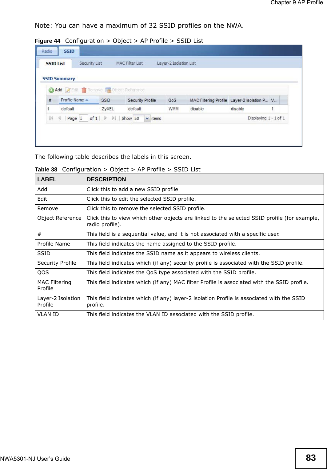
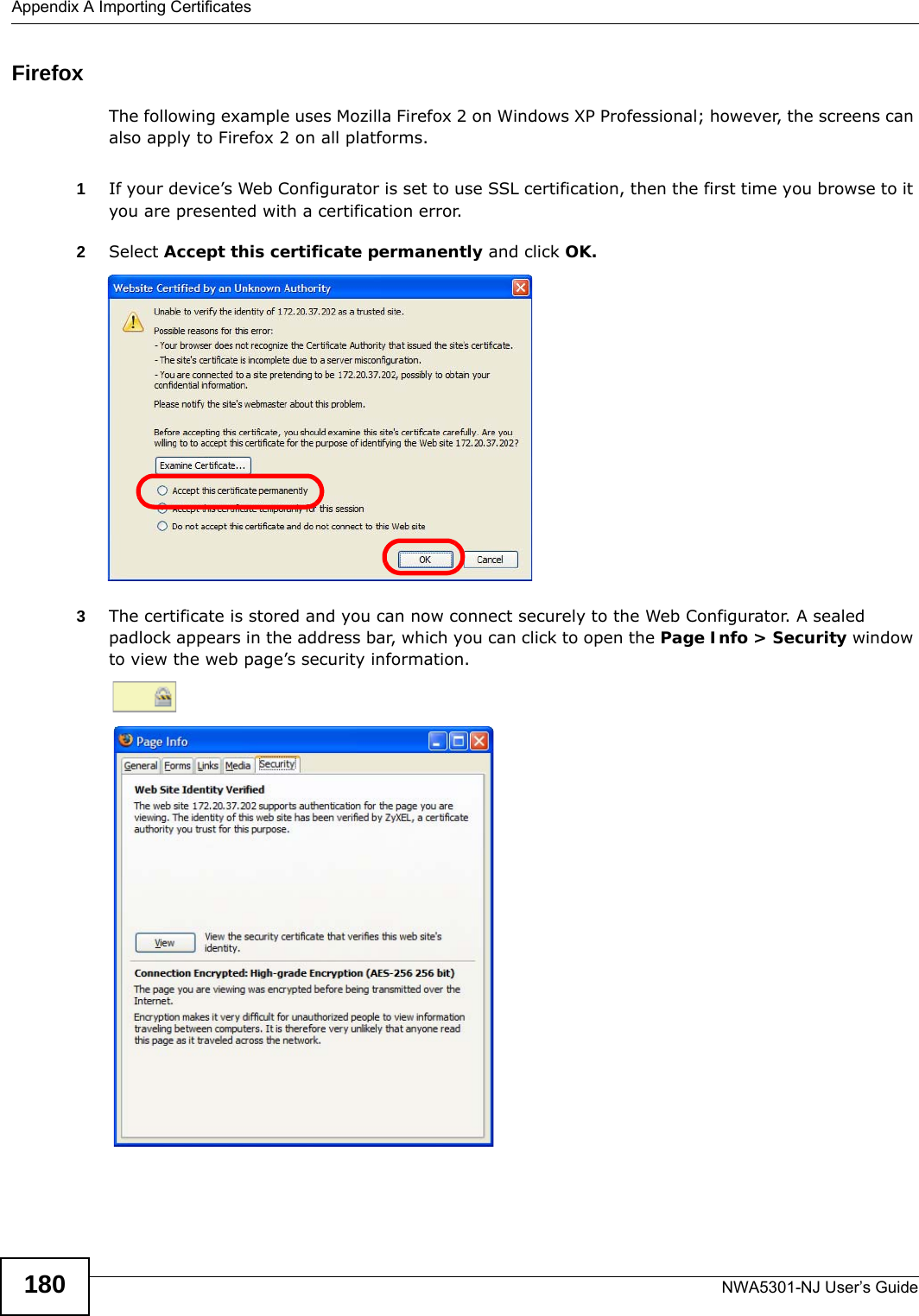
![Chapter 8 UserNWA5301-NJ User’s Guide 71• Alphanumeric A-z 0-9 (there is no unicode support)• _ [underscores] •- [dashes]The first character must be alphabetical (A-Z a-z), an underscore (_), or a dash (-). Other limitations on user names are:• User names are case-sensitive. If you enter a user 'bob' but use 'BOB' when connecting via CIFS or FTP, it will use the account settings used for 'BOB' not ‘bob’.• User names have to be different than user group names.• Here are the reserved user names:To access this screen, go to the User screen, and click Add or Edit.Figure 39 Configuration > Object > User > Add/Edit A User•adm •admin •any •bin •daemon•debug •devicehaecived•ftp •games •halt•ldap-users •lp •mail •news •nobody•operator •radius-users •root •shutdown •sshd•sync •uucp •zyxel](https://usermanual.wiki/ZyXEL-Communications/NWA5301NJ/User-Guide-2154980-Page-71.png)
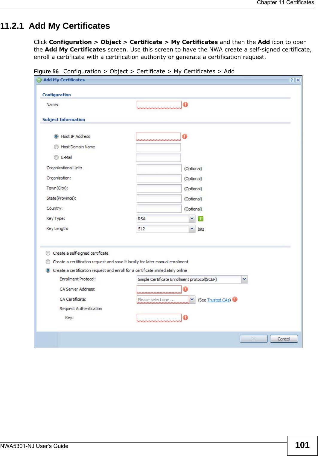
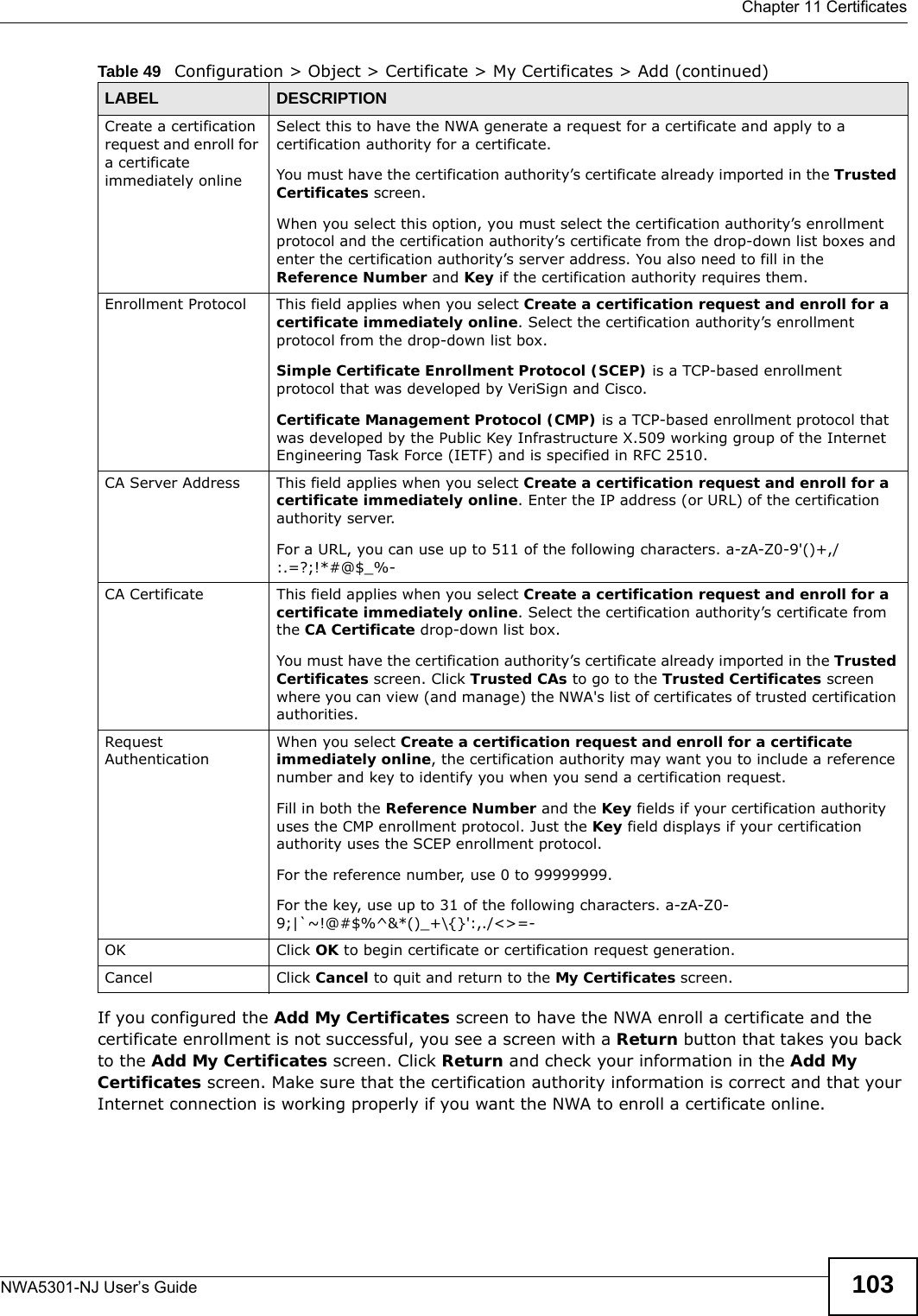
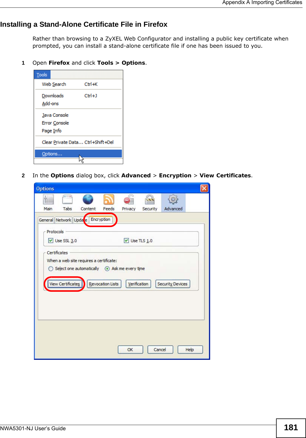
![Chapter 11 CertificatesNWA5301-NJ User’s Guide102The following table describes the labels in this screen. Table 49 Configuration > Object > Certificate > My Certificates > AddLABEL DESCRIPTIONName Type a name to identify this certificate. You can use up to 31 alphanumeric and ;‘~!@#$%^&()_+[]{}’,.=- characters.Subject Information Use these fields to record information that identifies the owner of the certificate. You do not have to fill in every field, although you must specify a Host IP Address, Host Domain Name, or E-Mail. The certification authority may add fields (such as a serial number) to the subject information when it issues a certificate. It is recommended that each certificate have unique subject information.Select a radio button to identify the certificate’s owner by IP address, domain name or e-mail address. Type the IP address (in dotted decimal notation), domain name or e-mail address in the field provided. The domain name or e-mail address is for identification purposes only and can be any string.A domain name can be up to 255 characters. You can use alphanumeric characters, the hyphen and periods.An e-mail address can be up to 63 characters. You can use alphanumeric characters, the hyphen, the @ symbol, periods and the underscore.Organizational Unit Identify the organizational unit or department to which the certificate owner belongs. You can use up to 31 characters. You can use alphanumeric characters, the hyphen and the underscore.Organization Identify the company or group to which the certificate owner belongs. You can use up to 31 characters. You can use alphanumeric characters, the hyphen and the underscore.Town (City) Identify the town or city where the certificate owner is located. You can use up to 31 characters. You can use alphanumeric characters, the hyphen and the underscore.State (Province) Identify the state or province where the certificate owner is located. You can use up to 31 characters. You can use alphanumeric characters, the hyphen and the underscore.Country Identify the nation where the certificate owner is located. You can use up to 31 characters. You can use alphanumeric characters, the hyphen and the underscore.Key Type Select RSA to use the Rivest, Shamir and Adleman public-key algorithm.Select DSA to use the Digital Signature Algorithm public-key algorithm.Key Length Select a number from the drop-down list box to determine how many bits the key should use (512 to 2048). The longer the key, the more secure it is. A longer key also uses more PKI storage space.Enrollment Options These radio buttons deal with how and when the certificate is to be generated.Create a self-signed certificateSelect this to have the NWA generate the certificate and act as the Certification Authority (CA) itself. This way you do not need to apply to a certification authority for certificates.Create a certification request and save it locally for later manual enrollmentSelect this to have the NWA generate and store a request for a certificate. Use the My Certificate Edit screen to view the certification request and copy it to send to the certification authority.Copy the certification request from the My Certificate Edit screen and then send it to the certification authority.](https://usermanual.wiki/ZyXEL-Communications/NWA5301NJ/User-Guide-2154980-Page-102.png)
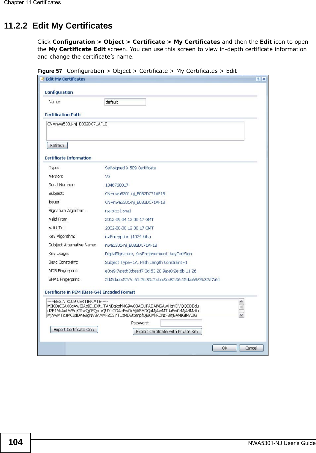
![Chapter 11 CertificatesNWA5301-NJ User’s Guide 105The following table describes the labels in this screen. Table 50 Configuration > Object > Certificate > My Certificates > EditLABEL DESCRIPTIONName This field displays the identifying name of this certificate. You can use up to 31 alphanumeric and ;‘~!@#$%^&()_+[]{}’,.=- characters.Certification Path This field displays for a certificate, not a certification request.Click the Refresh button to have this read-only text box display the hierarchy of certification authorities that validate the certificate (and the certificate itself).If the issuing certification authority is one that you have imported as a trusted certification authority, it may be the only certification authority in the list (along with the certificate itself). If the certificate is a self-signed certificate, the certificate itself is the only one in the list. The NWA does not trust the certificate and displays “Not trusted” in this field if any certificate on the path has expired or been revoked.Refresh Click Refresh to display the certification path.Certificate InformationThese read-only fields display detailed information about the certificate. Type This field displays general information about the certificate. CA-signed means that a Certification Authority signed the certificate. Self-signed means that the certificate’s owner signed the certificate (not a certification authority). “X.509” means that this certificate was created and signed according to the ITU-T X.509 recommendation that defines the formats for public-key certificates.Version This field displays the X.509 version number. “Serial Number This field displays the certificate’s identification number given by the certification authority or generated by the NWA.Subject This field displays information that identifies the owner of the certificate, such as Common Name (CN), Organizational Unit (OU), Organization (O), State (ST), and Country (C).Issuer This field displays identifying information about the certificate’s issuing certification authority, such as Common Name, Organizational Unit, Organization and Country. With self-signed certificates, this is the same as the Subject Name field.“none” displays for a certification request. Signature Algorithm This field displays the type of algorithm that was used to sign the certificate. The NWA uses rsa-pkcs1-sha1 (RSA public-private key encryption algorithm and the SHA1 hash algorithm). Some certification authorities may use rsa-pkcs1-md5 (RSA public-private key encryption algorithm and the MD5 hash algorithm).Valid From This field displays the date that the certificate becomes applicable. “none” displays for a certification request. Valid To This field displays the date that the certificate expires. The text displays in red and includes an Expired! message if the certificate has expired. “none” displays for a certification request. Key Algorithm This field displays the type of algorithm that was used to generate the certificate’s key pair (the NWA uses RSA encryption) and the length of the key set in bits (1024 bits for example).Subject Alternative NameThis field displays the certificate owner‘s IP address (IP), domain name (DNS) or e-mail address (EMAIL). Key Usage This field displays for what functions the certificate’s key can be used. For example, “DigitalSignature” means that the key can be used to sign certificates and “KeyEncipherment” means that the key can be used to encrypt text.Basic Constraint This field displays general information about the certificate. For example, Subject Type=CA means that this is a certification authority’s certificate and “Path Length Constraint=1” means that there can only be one certification authority in the certificate’s path. This field does not display for a certification request.](https://usermanual.wiki/ZyXEL-Communications/NWA5301NJ/User-Guide-2154980-Page-105.png)
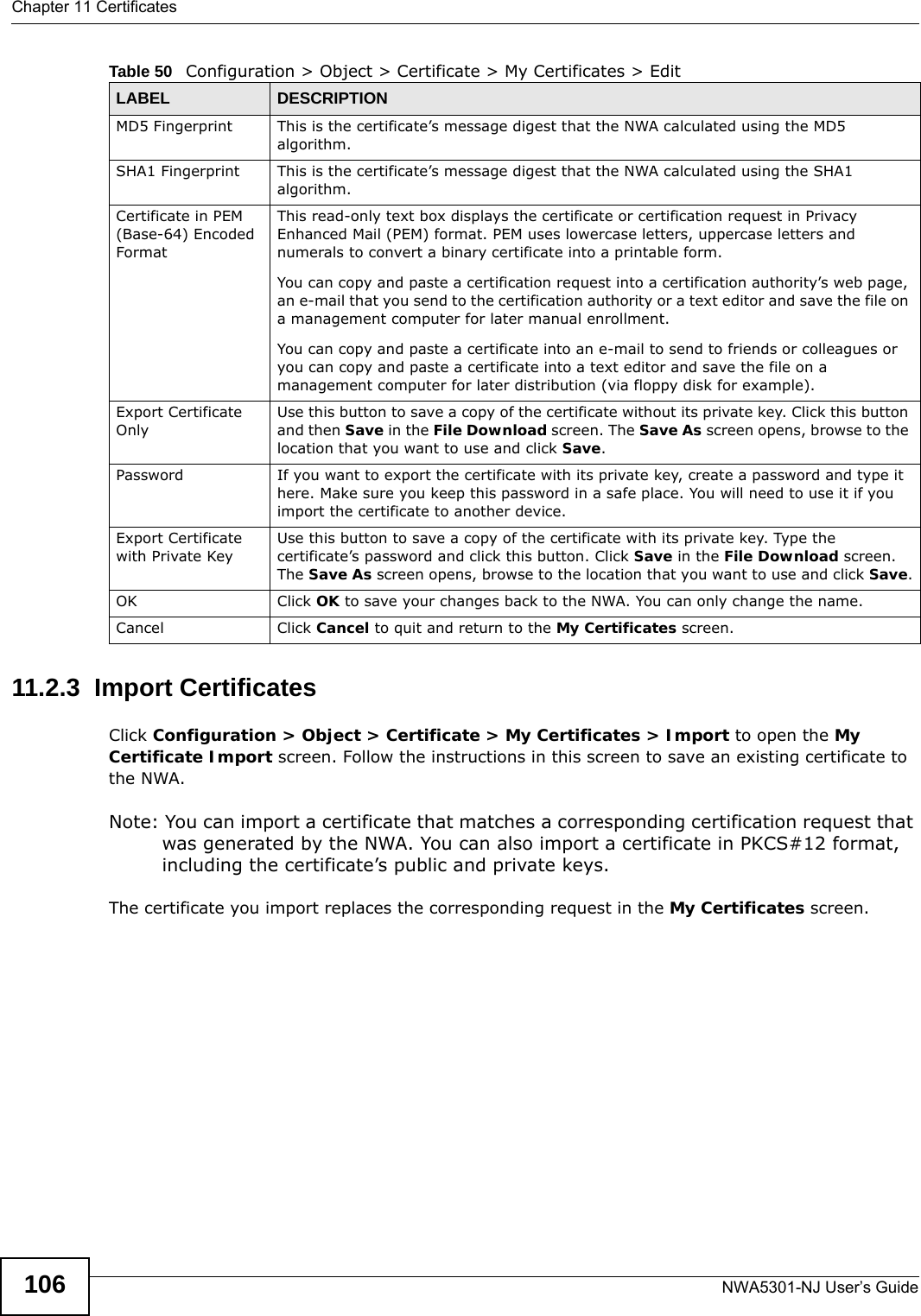
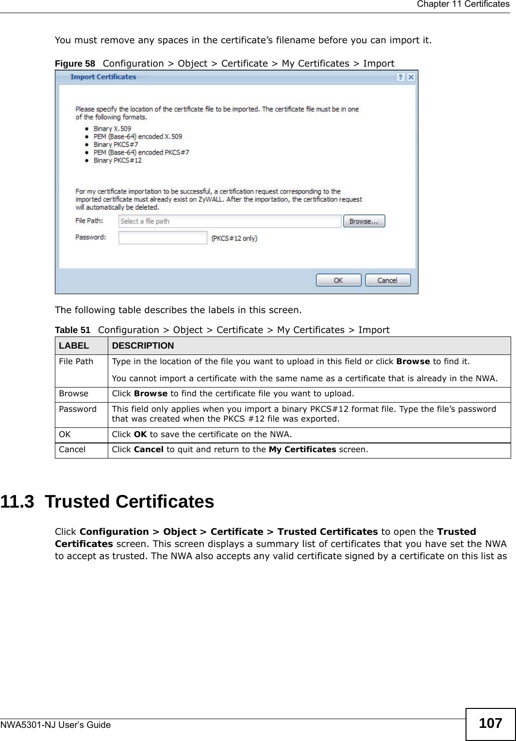
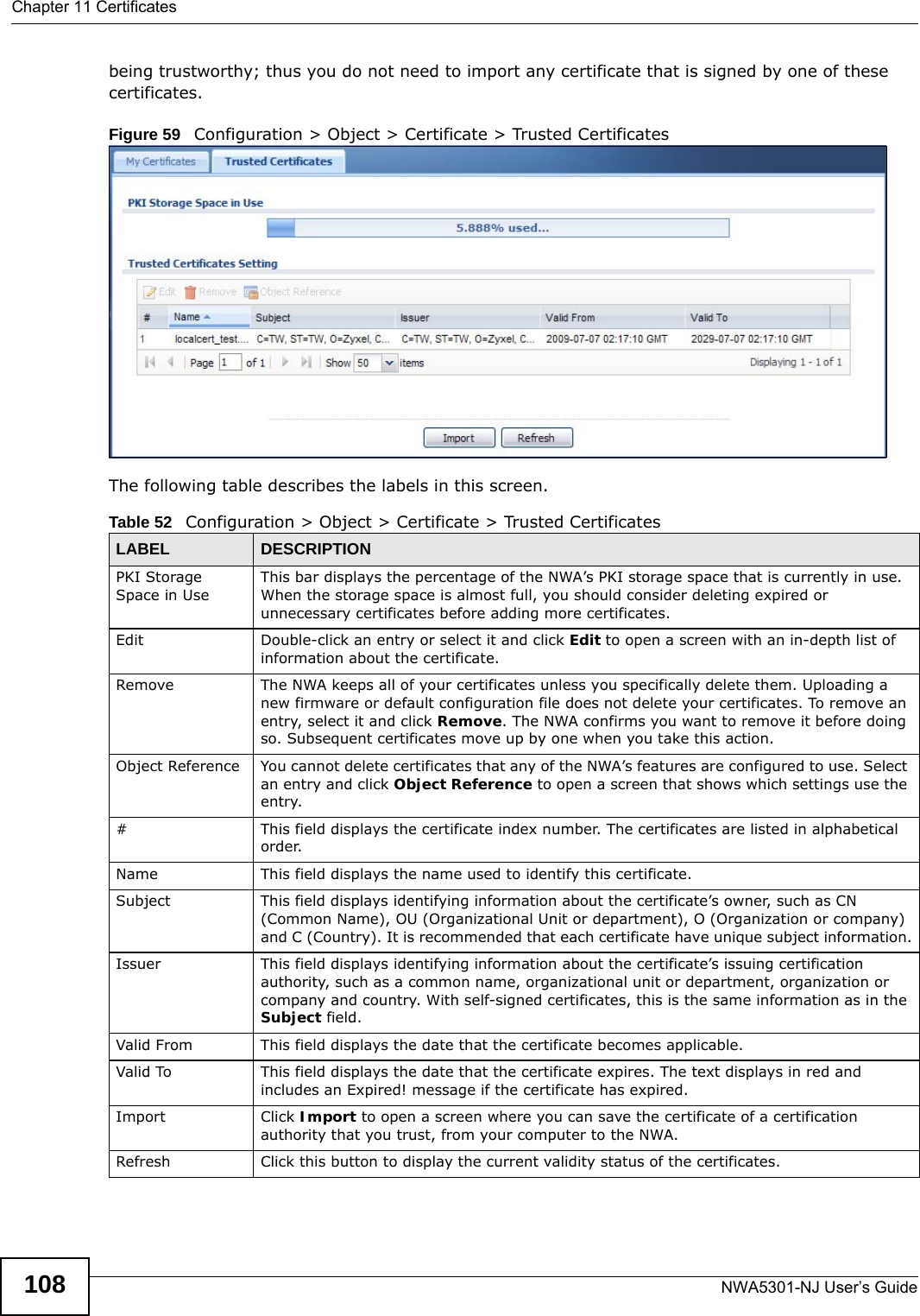
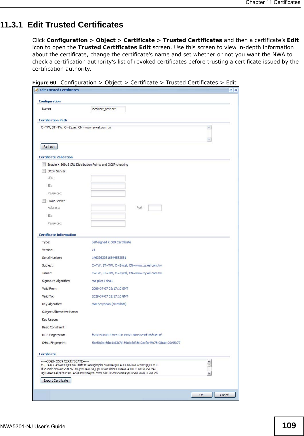
![Chapter 11 CertificatesNWA5301-NJ User’s Guide110The following table describes the labels in this screen. Table 53 Configuration > Object > Certificate > Trusted Certificates > EditLABEL DESCRIPTIONName This field displays the identifying name of this certificate. You can change the name. You can use up to 31 alphanumeric and ;‘~!@#$%^&()_+[]{}’,.=- characters.Certification Path Click the Refresh button to have this read-only text box display the end entity’s certificate and a list of certification authority certificates that shows the hierarchy of certification authorities that validate the end entity’s certificate. If the issuing certification authority is one that you have imported as a trusted certificate, it may be the only certification authority in the list (along with the end entity’s own certificate). The NWA does not trust the end entity’s certificate and displays “Not trusted” in this field if any certificate on the path has expired or been revoked.Refresh Click Refresh to display the certification path.Enable X.509v3 CRL Distribution Points and OCSP checking Select this check box to have the NWA check incoming certificates that are signed by this certificate against a Certificate Revocation List (CRL) or an OCSP server. You also need to configure the OSCP or LDAP server details.OCSP Server Select this check box if the directory server uses OCSP (Online Certificate Status Protocol).URL Type the protocol, IP address and pathname of the OCSP server. ID The NWA may need to authenticate itself in order to assess the OCSP server. Type the login name (up to 31 ASCII characters) from the entity maintaining the server (usually a certification authority).Password Type the password (up to 31 ASCII characters) from the entity maintaining the OCSP server (usually a certification authority).LDAP Server Select this check box if the directory server uses LDAP (Lightweight Directory Access Protocol). LDAP is a protocol over TCP that specifies how clients access directories of certificates and lists of revoked certificates.Address Type the IP address (in dotted decimal notation) of the directory server. Port Use this field to specify the LDAP server port number. You must use the same server port number that the directory server uses. 389 is the default server port number for LDAP.ID The NWA may need to authenticate itself in order to assess the CRL directory server. Type the login name (up to 31 ASCII characters) from the entity maintaining the server (usually a certification authority).Password Type the password (up to 31 ASCII characters) from the entity maintaining the CRL directory server (usually a certification authority).Certificate InformationThese read-only fields display detailed information about the certificate. Type This field displays general information about the certificate. CA-signed means that a Certification Authority signed the certificate. Self-signed means that the certificate’s owner signed the certificate (not a certification authority). X.509 means that this certificate was created and signed according to the ITU-T X.509 recommendation that defines the formats for public-key certificates.Version This field displays the X.509 version number. Serial Number This field displays the certificate’s identification number given by the certification authority.Subject This field displays information that identifies the owner of the certificate, such as Common Name (CN), Organizational Unit (OU), Organization (O) and Country (C).Issuer This field displays identifying information about the certificate’s issuing certification authority, such as Common Name, Organizational Unit, Organization and Country. With self-signed certificates, this is the same information as in the Subject Name field.](https://usermanual.wiki/ZyXEL-Communications/NWA5301NJ/User-Guide-2154980-Page-110.png)
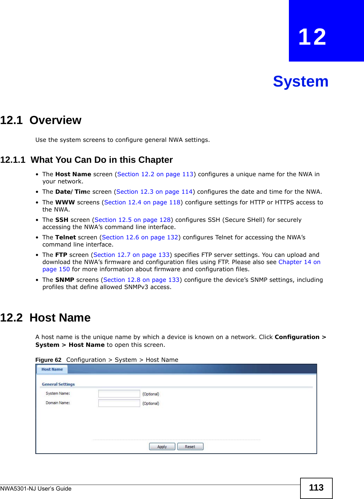
![Chapter 12 SystemNWA5301-NJ User’s Guide 13112.5.5 Examples of Secure Telnet Using SSHThis section shows two examples using a command interface and a graphical interface SSH client program to remotely access the NWA. The configuration and connection steps are similar for most SSH client programs. Refer to your SSH client program user’s guide.12.5.5.1 Example 1: Microsoft Windows This section describes how to access the NWA using the Secure Shell Client program.1Launch the SSH client and specify the connection information (IP address, port number) for the NWA. 2Configure the SSH client to accept connection using SSH version 1. 3A window displays prompting you to store the host key in you computer. Click Yes to continue. Figure 75 SSH Example 1: Store Host KeyEnter the password to log in to the NWA. The CLI screen displays next. 12.5.5.2 Example 2: LinuxThis section describes how to access the NWA using the OpenSSH client program that comes with most Linux distributions. 1Test whether the SSH service is available on the NWA. Enter “telnet 192.168.1.2 22” at a terminal prompt and press [ENTER]. The computer attempts to connect to port 22 on the NWA (using the default IP address of 192.168.1.2). A message displays indicating the SSH protocol version supported by the NWA. Figure 76 SSH Example 2: Test $ telnet 192.168.1.2 22Trying 192.168.1.2...Connected to 192.168.1.2.Escape character is '^]'.SSH-1.5-1.0.0](https://usermanual.wiki/ZyXEL-Communications/NWA5301NJ/User-Guide-2154980-Page-131.png)
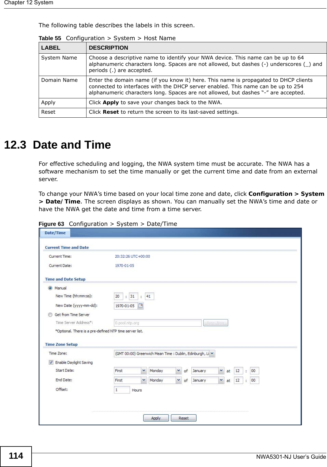
![Chapter 12 SystemNWA5301-NJ User’s Guide1322Enter “ssh –1 192.168.1.2”. This command forces your computer to connect to the NWA using SSH version 1. If this is the first time you are connecting to the NWA using SSH, a message displays prompting you to save the host information of the NWA. Type “yes” and press [ENTER]. Then enter the password to log in to the NWA. Figure 77 SSH Example 2: Log in3The CLI screen displays next. 12.6 Telnet You can use Telnet to access the NWA’s command line interface. Click Configuration > System > TELNET to configure your NWA for remote Telnet access. Use this screen to enable or disable Telnet and set the server port number. Figure 78 Configuration > System > TELNETThe following table describes the labels in this screen. $ ssh –1 192.168.1.2The authenticity of host '192.168.1.2 (192.168.1.2)' can't be established.RSA1 key fingerprint is 21:6c:07:25:7e:f4:75:80:ec:af:bd:d4:3d:80:53:d1.Are you sure you want to continue connecting (yes/no)? yesWarning: Permanently added '192.168.1.2' (RSA1) to the list of known hosts.Administrator@192.168.1.2's password:Table 60 Configuration > System > TELNETLABEL DESCRIPTIONEnable Select the check box to allow or disallow the computer with the IP address that matches the IP address(es) in the Service Control table to access the NWA CLI using this service.Server Port You may change the server port number for a service if needed, however you must use the same port number in order to use that service for remote management.Apply Click Apply to save your changes back to the NWA. Reset Click Reset to return the screen to its last-saved settings.](https://usermanual.wiki/ZyXEL-Communications/NWA5301NJ/User-Guide-2154980-Page-132.png)
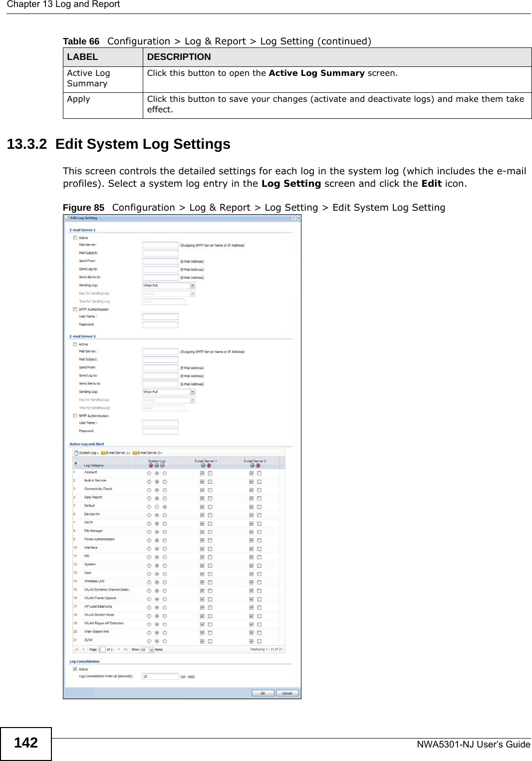
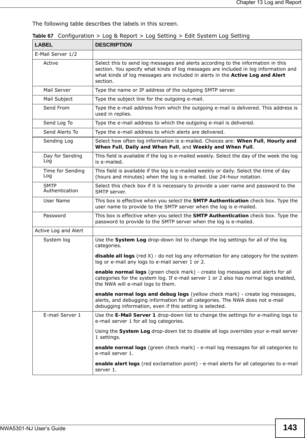
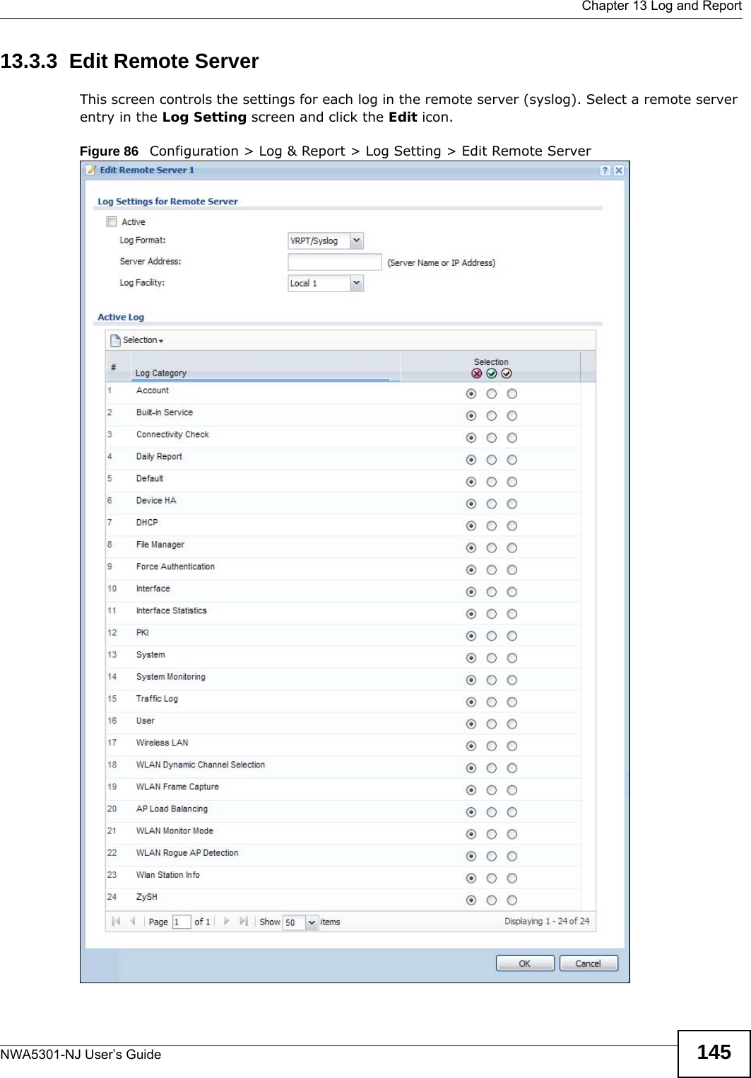
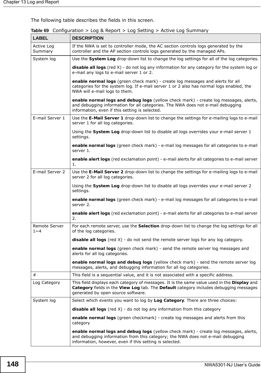
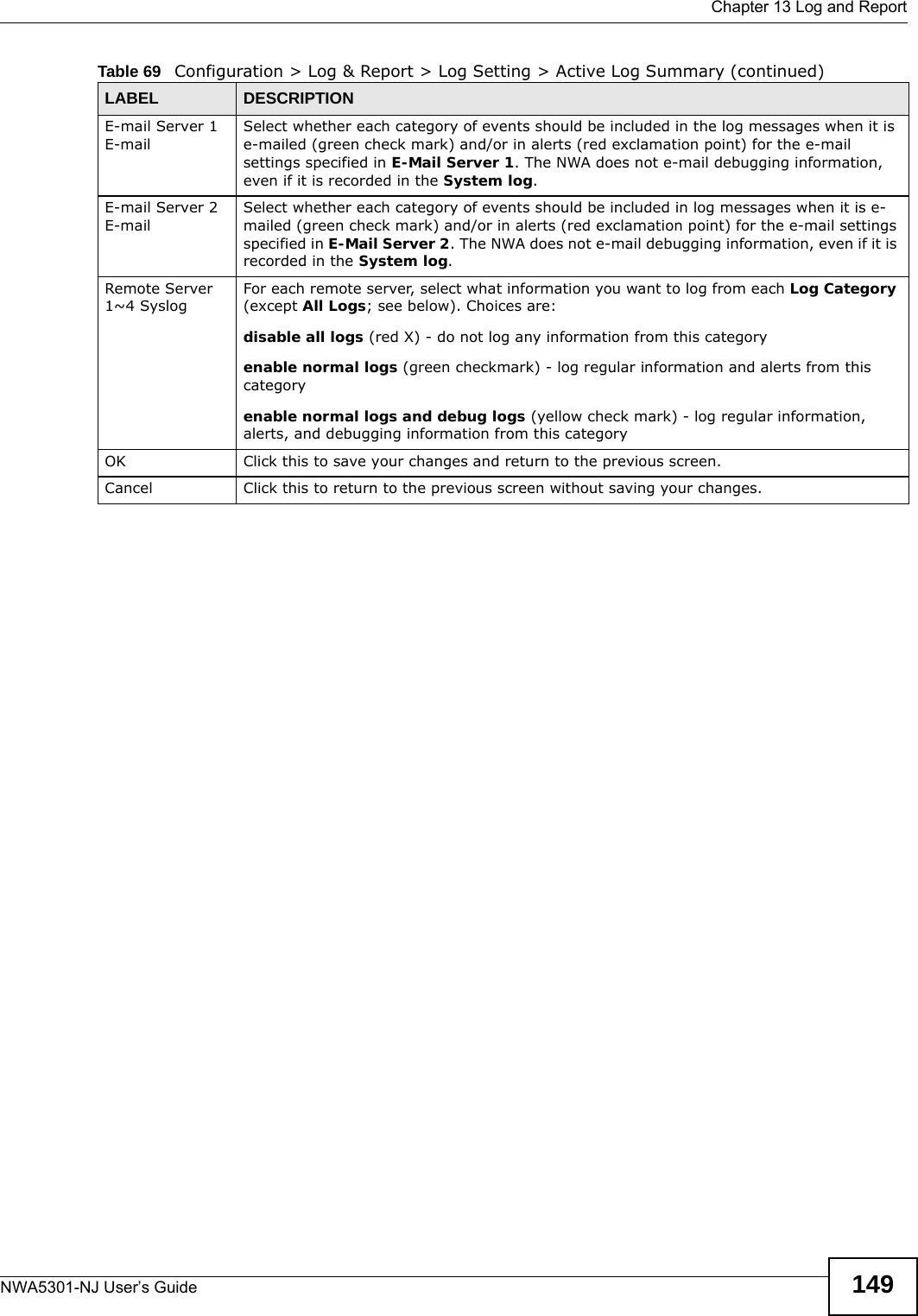
![Chapter 13 Log and ReportNWA5301-NJ User’s Guide144E-mail Server 2 Use the E-Mail Server 2 drop-down list to change the settings for e-mailing logs to e-mail server 2 for all log categories.Using the System Log drop-down list to disable all logs overrides your e-mail server 2 settings.enable normal logs (green check mark) - e-mail log messages for all categories to e-mail server 2.enable alert logs (red exclamation point) - e-mail alerts for all categories to e-mail server 2.# This field is a sequential value, and it is not associated with a specific address.Log Category This field displays each category of messages. It is the same value used in the Display and Category fields in the View Log tab. The Default category includes debugging messages generated by open source software.System log Select which events you want to log by Log Category. There are three choices:disable all logs (red X) - do not log any information from this categoryenable normal logs (green checkmark) - create log messages and alerts from this categoryenable normal logs and debug logs (yellow check mark) - create log messages, alerts, and debugging information from this category; the NWA does not e-mail debugging information, however, even if this setting is selected.E-mail Server 1 Select whether each category of events should be included in the log messages when it is e-mailed (green check mark) and/or in alerts (red exclamation point) for the e-mail settings specified in E-Mail Server 1. The NWA does not e-mail debugging information, even if it is recorded in the System log.E-mail Server 2 Select whether each category of events should be included in log messages when it is e-mailed (green check mark) and/or in alerts (red exclamation point) for the e-mail settings specified in E-Mail Server 2. The NWA does not e-mail debugging information, even if it is recorded in the System log.Log ConsolidationActive Select this to activate log consolidation. Log consolidation aggregates multiple log messages that arrive within the specified Log Consolidation Interval. In the View Log tab, the text “[count=x]”, where x is the number of original log messages, is appended at the end of the Message field, when multiple log messages were aggregated.Log Consolidation Interval Type how often, in seconds, to consolidate log information. If the same log message appears multiple times, it is aggregated into one log message with the text “[count=x]”, where x is the number of original log messages, appended at the end of the Message field.OK Click this to save your changes and return to the previous screen.Cancel Click this to return to the previous screen without saving your changes.Table 67 Configuration > Log & Report > Log Setting > Edit System Log Setting (continued)LABEL DESCRIPTION](https://usermanual.wiki/ZyXEL-Communications/NWA5301NJ/User-Guide-2154980-Page-144.png)

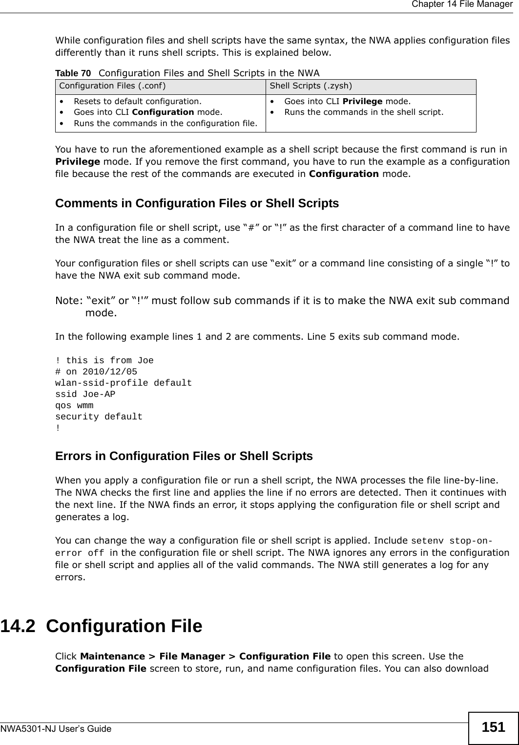
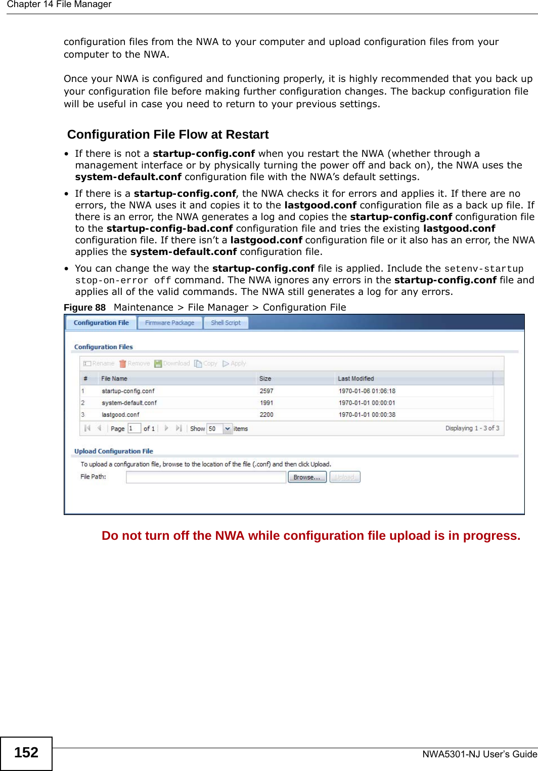
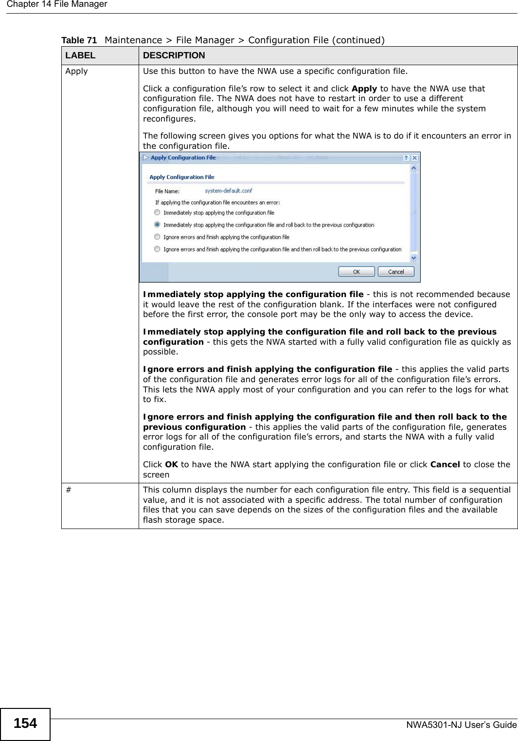
![Chapter 14 File ManagerNWA5301-NJ User’s Guide 153The following table describes the labels in this screen. Table 71 Maintenance > File Manager > Configuration FileLABEL DESCRIPTIONRename Use this button to change the label of a configuration file on the NWA. You can only rename manually saved configuration files. You cannot rename the lastgood.conf, system-default.conf and startup-config.conf files. You cannot rename a configuration file to the name of another configuration file in the NWA. Click a configuration file’s row to select it and click Rename to open the Rename File screen. Specify the new name for the configuration file. Use up to 25 characters (including a-zA-Z0-9;‘~!@#$%^&()_+[]{}’,.=-). Click OK to save the duplicate or click Cancel to close the screen without saving a duplicate of the configuration file.Remove Click a configuration file’s row to select it and click Remove to delete it from the NWA. You can only delete manually saved configuration files. You cannot delete the system-default.conf, startup-config.conf and lastgood.conf files.A pop-up window asks you to confirm that you want to delete the configuration file. Click OK to delete the configuration file or click Cancel to close the screen without deleting the configuration file.Download Click a configuration file’s row to select it and click Download to save the configuration to your computer.Copy Use this button to save a duplicate of a configuration file on the NWA. Click a configuration file’s row to select it and click Copy to open the Copy File screen. Specify a name for the duplicate configuration file. Use up to 25 characters (including a-zA-Z0-9;‘~!@#$%^&()_+[]{}’,.=-). Click OK to save the duplicate or click Cancel to close the screen without saving a duplicate of the configuration file.](https://usermanual.wiki/ZyXEL-Communications/NWA5301NJ/User-Guide-2154980-Page-153.png)
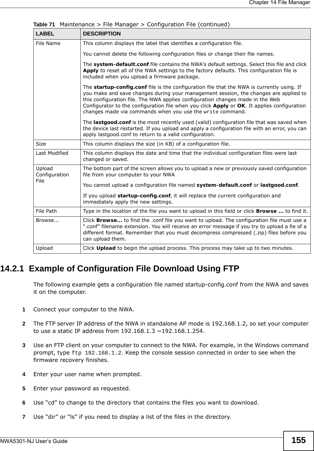
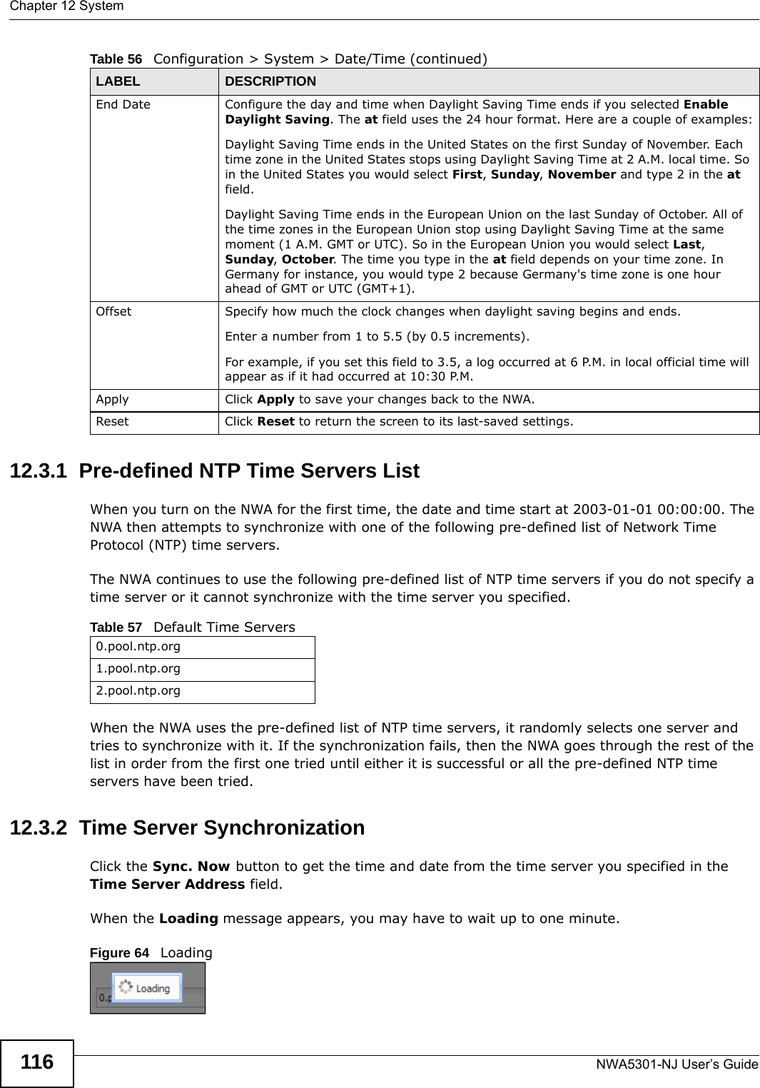
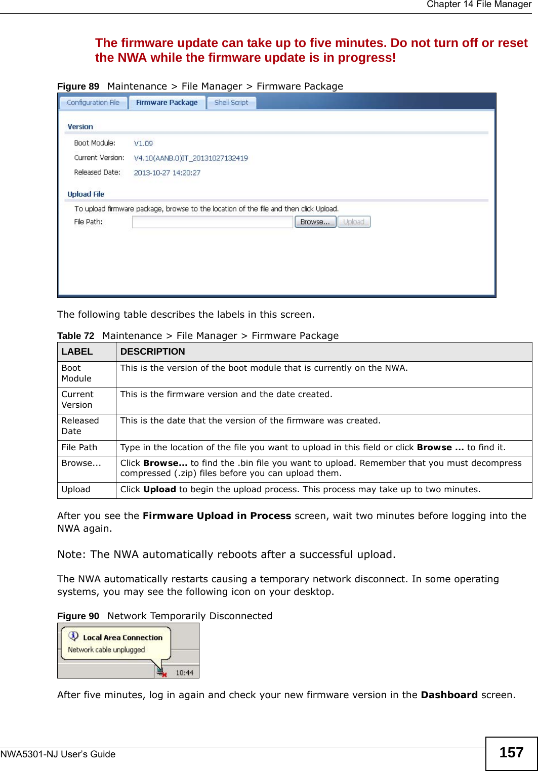
![Chapter 14 File ManagerNWA5301-NJ User’s Guide1568Use "get” to download files. Transfer the configuration file on the NWA to your computer. Type get followed by the name of the configuration file. This examples uses get startup-config.conf. 9Wait for the file transfer to complete.10 Enter “quit” to exit the ftp prompt.14.3 Firmware Package Click Maintenance > File Manager > Firmware Package to open this screen. Use the Firmware Package screen to check your current firmware version and upload firmware to the NWA.Note: The Web Configurator is the recommended method for uploading firmware. You only need to use the command line interface if you need to recover the firmware. See the CLI Reference Guide for how to determine if you need to recover the firmware and how to recover it.Find the firmware package at www.zyxel.com in a file that (usually) uses a .bin extension. C:\>ftp 192.168.1.2Connected to 192.168.1.2.220---------- Welcome to Pure-FTPd [privsep] [TLS] ----------220-You are user number 1 of 5 allowed.220-Local time is now 21:28. Server port: 21.220-This is a private system - No anonymous login220 You will be disconnected after 600 minutes of inactivity.User (192.168.1.2:(none)): admin331 User admin OK. Password requiredPassword:230 OK. Current restricted directory is /ftp> cd conf250 OK. Current directory is /confftp> ls200 PORT command successful150 Connecting to port 5001lastgood.confstartup-config.confsystem-default.conf226 3 matches totalftp: 57 bytes received in 0.33Seconds 0.17Kbytes/sec.ftp> get startup-config.conf200 PORT command successful150 Connecting to port 5002226-File successfully transferred226 0.002 seconds (measured here), 1.66 Mbytes per secondftp: 2928 bytes received in 0.02Seconds 183.00Kbytes/sec.ftp>](https://usermanual.wiki/ZyXEL-Communications/NWA5301NJ/User-Guide-2154980-Page-156.png)
![Chapter 14 File ManagerNWA5301-NJ User’s Guide15814.3.1 Example of Firmware Upload Using FTPThis procedure requires the NWA’s firmware. Download the firmware package from www.zyxel.com and unzip it. The firmware file uses a .bin extension, for example, "410AANB0C0.bin". Do the following after you have obtained the firmware file.1Connect your computer to the NWA. 2The FTP server IP address of the NWA in standalone AP mode is 192.168.1.2, so set your computer to use a static IP address from 192.168.1.3 ~192.168.1.254.3Use an FTP client on your computer to connect to the NWA. For example, in the Windows command prompt, type ftp 192.168.1.2. Keep the console session connected in order to see when the firmware recovery finishes. 4Enter your user name when prompted.5Enter your password as requested.6Enter “hash” for FTP to print a `#' character for every 1024 bytes of data you upload so that you can watch the file transfer progress.7Enter “bin” to set the transfer mode to binary.8Transfer the firmware file from your computer to the NWA. Type put followed by the path and name of the firmware file. This examples uses put C:\ftproot\NWA_FW\410AANB0C0.bin. 9Wait for the file transfer to complete.10 Enter “quit” to exit the ftp prompt.14.4 Shell Script Use shell script files to have the NWA use commands that you specify. Use a text editor to create the shell script files. They must use a “.zysh” filename extension. C:\>ftp 192.168.1.2Connected to 192.168.1.2.220---------- Welcome to Pure-FTPd [privsep] [TLS] ----------220-You are user number 1 of 5 allowed.220-Local time is now 21:28. Server port: 21.220-This is a private system - No anonymous login220 You will be disconnected after 600 minutes of inactivity.User (192.168.1.2:(none)): admin331 User admin OK. Password requiredPassword:230 OK. Current restricted directory is /ftp> hash Hash mark printing On ftp: (2048 bytes/hash mark) .ftp> bin200 TYPE is now 8-bit binaryftp> put C:\ftproot\NWA_FW\410AANB0C0.bin](https://usermanual.wiki/ZyXEL-Communications/NWA5301NJ/User-Guide-2154980-Page-158.png)
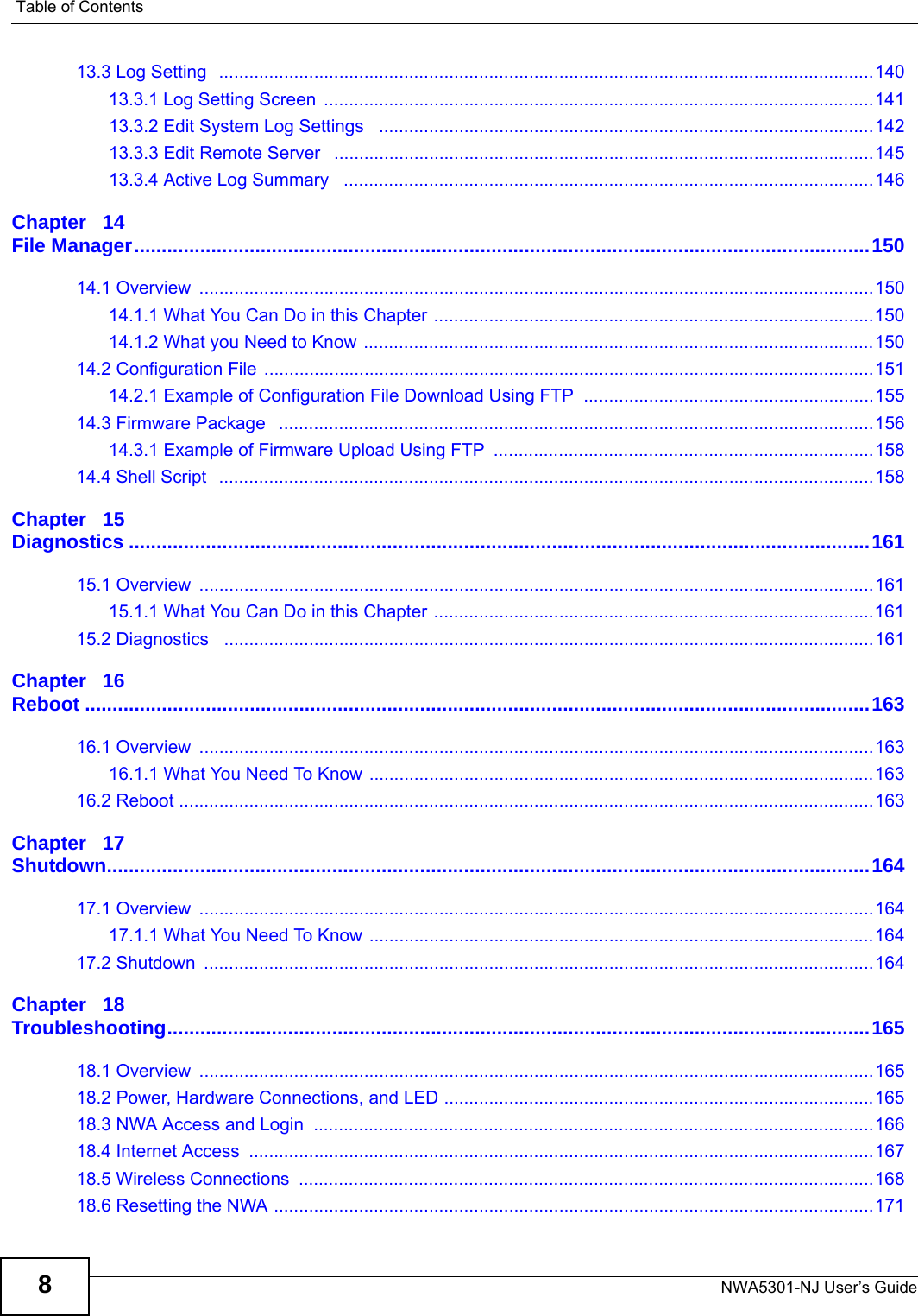
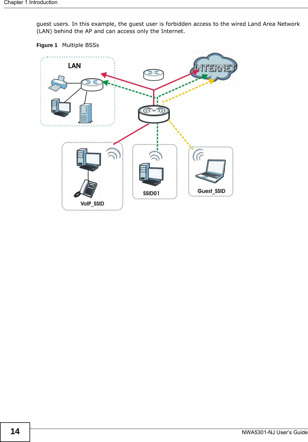
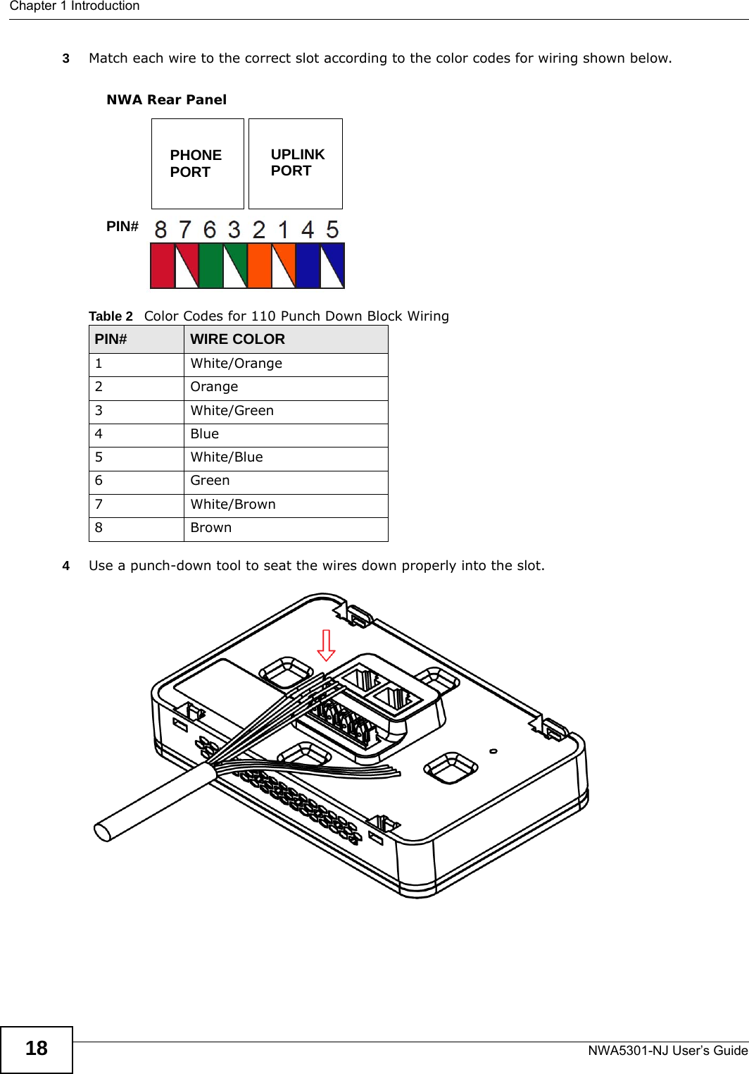
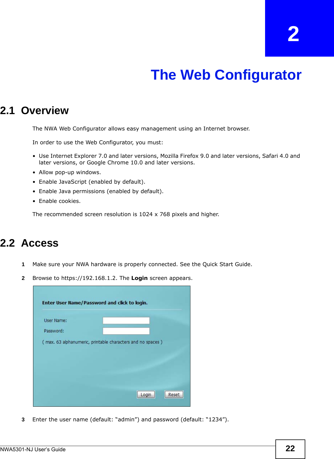
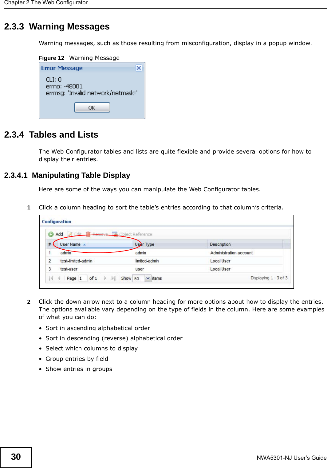
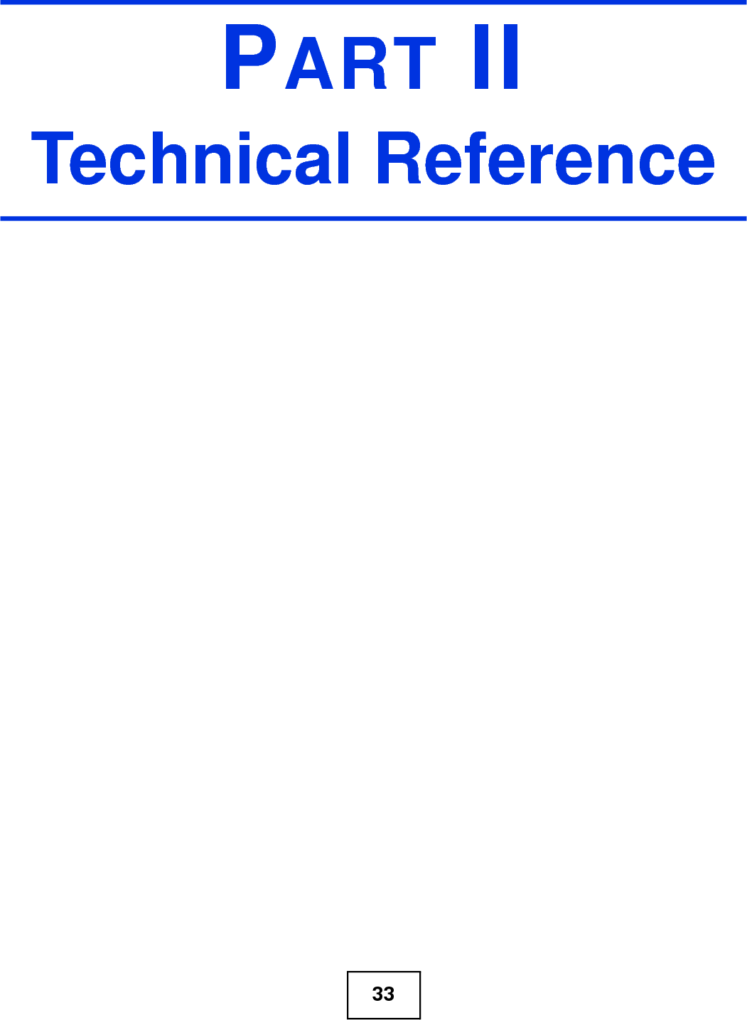
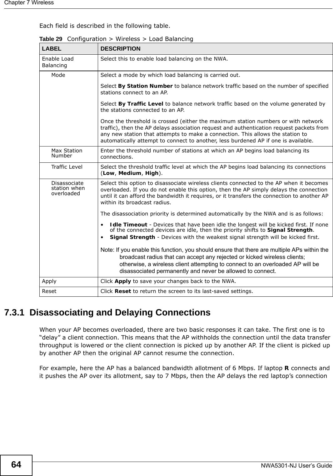
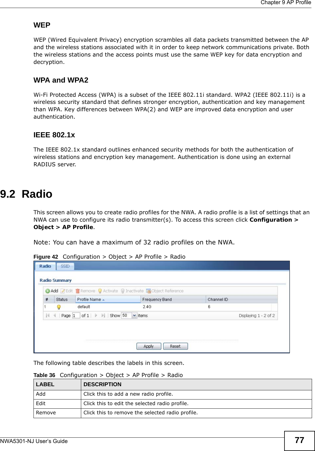
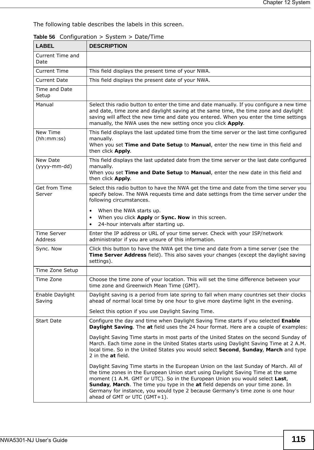
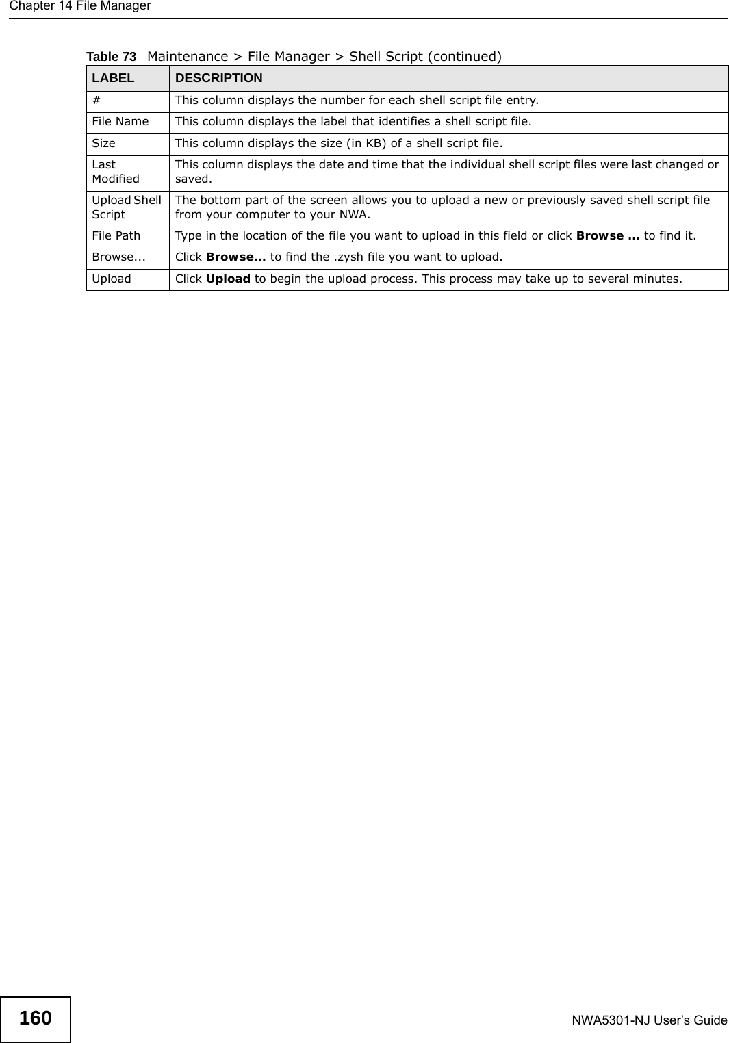
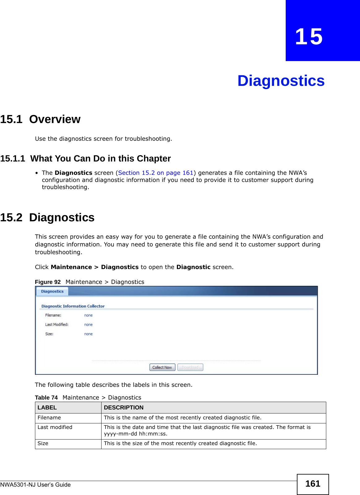
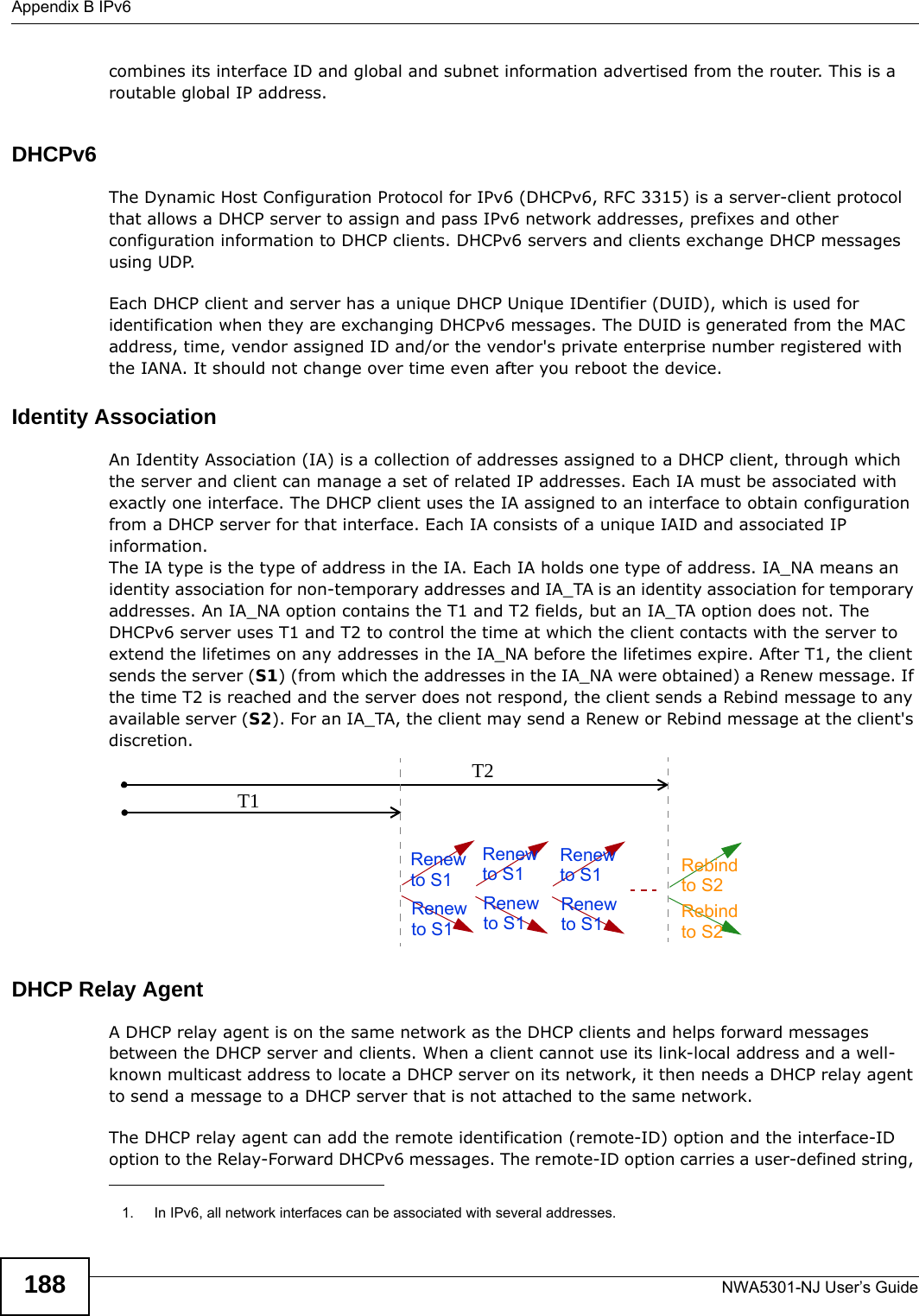
![Chapter 14 File ManagerNWA5301-NJ User’s Guide 159Click Maintenance > File Manager > Shell Script to open this screen. Use the Shell Script screen to store, name, download, upload and run shell script files. You can store multiple shell script files on the NWA at the same time. Note: You should include write commands in your scripts. If you do not use the write command, the changes will be lost when the NWA restarts. You could use multiple write commands in a long script.Figure 91 Maintenance > File Manager > Shell Script Each field is described in the following table. Table 73 Maintenance > File Manager > Shell ScriptLABEL DESCRIPTIONRename Use this button to change the label of a shell script file on the NWA. You cannot rename a shell script to the name of another shell script in the NWA. Click a shell script’s row to select it and click Rename to open the Rename File screen. Specify the new name for the shell script file. Use up to 25 characters (including a-zA-Z0-9;‘~!@#$%^&()_+[]{}’,.=-). Click OK to save the duplicate or click Cancel to close the screen without saving a duplicate of the configuration file.Remove Click a shell script file’s row to select it and click Delete to delete the shell script file from the NWA. A pop-up window asks you to confirm that you want to delete the shell script file. Click OK to delete the shell script file or click Cancel to close the screen without deleting the shell script file.Download Click a shell script file’s row to select it and click Download to save the configuration to your computer.Copy Use this button to save a duplicate of a shell script file on the NWA. Click a shell script file’s row to select it and click Copy to open the Copy File screen. Specify a name for the duplicate file. Use up to 25 characters (including a-zA-Z0-9;‘~!@#$%^&()_+[]{}’,.=-). Click OK to save the duplicate or click Cancel to close the screen without saving a duplicate of the configuration file.Run Use this button to have the NWA use a specific shell script file.Click a shell script file’s row to select it and click Run to have the NWA use that shell script file. You may need to wait awhile for the NWA to finish applying the commands.](https://usermanual.wiki/ZyXEL-Communications/NWA5301NJ/User-Guide-2154980-Page-159.png)
![Chapter 18 TroubleshootingNWA5301-NJ User’s Guide 167• Try to access the NWA using another service, such as Telnet. If you can access the NWA, check the remote management settings to find out why the NWA does not respond to HTTP. • If your computer is connected wirelessly, use a computer that is connected to a LAN/ETHERNET port.I forgot the password.1The default password is 1234.2If this does not work, you have to reset the device to its factory defaults. See Section 18.6 on page 171.I can see the Login screen, but I cannot log in to the NWA.1Make sure you have entered the user name and password correctly. The default password is 1234. This fields are case-sensitive, so make sure [Caps Lock] is not on.2You cannot log in to the web configurator while someone is using Telnet to access the NWA. Log out of the NWA in the other session, or ask the person who is logged in to log out.3Disconnect and re-connect the PoE power injector to the NWA. 4If this does not work, you have to reset the device to its factory defaults. See Section 18.6 on page 171.I cannot use FTP to upload / download the configuration file. / I cannot use FTP to upload new firmware. See the troubleshooting suggestions for I cannot see or access the Login screen in the web configurator. Ignore the suggestions about your browser.18.4 Internet AccessI cannot access the Internet.1Check the hardware connections, and make sure the LED is behaving as expected. See the Quick Start Guide and Section 18.2 on page 165.](https://usermanual.wiki/ZyXEL-Communications/NWA5301NJ/User-Guide-2154980-Page-167.png)
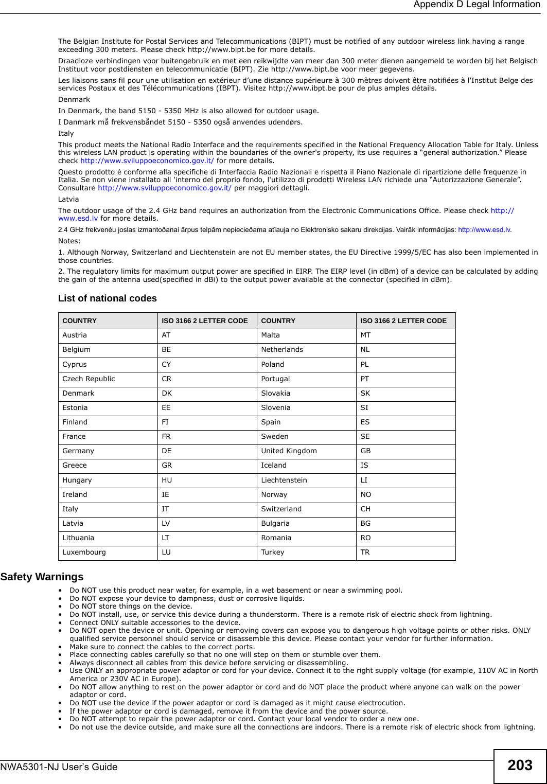
![Appendix D Legal InformationNWA5301-NJ User’s Guide 201注意 ! 依據 低功率電波輻射性電機管理辦法第十二條 經型式認證合格之低功率射頻電機,非經許可,公司、商號或使用者均不得擅自變更頻率、加大功率或變更原設計之特性及功能。第十四條 低功率射頻電機之使用不得影響飛航安全及干擾合法通信;經發現有干擾現象時,應立即停用,並改善至無干擾時方得繼續使用。前項合法通信,指依電信規定作業之無線電信。低功率射頻電機須忍受合法通信或工業、科學及醫療用電波輻射性電機設備之干擾。本機限在不干擾合法電臺與不受被干擾保障條件下於室內使用。 減少電磁波影響,請妥適使用。Notices Changes or modifications not expressly approved by the party responsible for compliance could void the user's authority to operate the equipment.This Class B digital apparatus complies with Canadian ICES-003.Cet appareil numérique de la classe B est conforme à la norme NMB-003 du Canada.Viewing CertificationsGo to http://www.zyxel.com to view this product’s documentation and certifications.ZyXEL Limited WarrantyZyXEL warrants to the original end user (purchaser) that this product is free from any defects in material or workmanship for a specific period (the Warranty Period) from the date of purchase. The Warranty Period varies by region. Check with your vendor and/or the authorized ZyXEL local distributor for details about the Warranty Period of this product. During the warranty period, and upon proof of purchase, should the product have indications of failure due to faulty workmanship and/or materials, ZyXEL will, at its discretion, repair or replace the defective products or components without charge for either parts or labor, and to whatever extent it shall deem necessary to restore the product or components to proper operating condition. Any replacement will consist of a new or re-manufactured functionally equivalent product of equal or higher value, and will be solely at the discretion of ZyXEL. This warranty shall not apply if the product has been modified, misused, tampered with, damaged by an act of God, or subjected to abnormal working conditions.NoteRepair or replacement, as provided under this warranty, is the exclusive remedy of the purchaser. This warranty is in lieu of all other warranties, express or implied, including any implied warranty of merchantability or fitness for a particular use or purpose. ZyXEL shall in no event be held liable for indirect or consequential damages of any kind to the purchaser.To obtain the services of this warranty, contact your vendor. You may also refer to the warranty policy for the region in which you bought the device at http://www.zyxel.com/web/support_warranty_info.php.RegistrationRegister your product online to receive e-mail notices of firmware upgrades and information at www.zyxel.com.Open Source LicensesThis product contains in part some free software distributed under GPL license terms and/or GPL like licenses. Open source licenses are provided with the firmware package. You can download the latest firmware at www.zyxel.com. If you cannot find it there, contact your vendor or ZyXEL Technical Support at support@zyxel.com.tw. To obtain the source code covered under those Licenses, please contact your vendor or ZyXEL Technical Support at support@zyxel.com.tw. Regulatory InformationEuropean UnionThe following information applies if you use the product within the European Union. Declaration of Conformity with Regard to EU Directive 1999/5/EC (R&TTE Directive)Compliance Information for 2.4GHz and 5GHz Wireless Products Relevant to the EU and Other Countries Following the EU Directive 1999/5/EC (R&TTE Directive) [Czech] ZyXEL tímto prohlašuje, že tento zařízení je ve shodě se základními požadavky a dalšími příslušnými ustanoveními směrnice 1999/5/EC.[Danish] Undertegnede ZyXEL erklærer herved, at følgende udstyr udstyr overholder de væsentlige krav og øvrige relevante krav i direktiv 1999/5/EF.[German] Hiermit erklärt ZyXEL, dass sich das Gerät Ausstattung in Übereinstimmung mit den grundlegenden Anforderungen und den übrigen einschlägigen Bestimmungen der Richtlinie 1999/5/EU befindet.[Estonian] Käesolevaga kinnitab ZyXEL seadme seadmed vastavust direktiivi 1999/5/EÜ põhinõuetele ja nimetatud direktiivist tulenevatele teistele asjakohastele sätetele.English Hereby, ZyXEL declares that this equipment is in compliance with the essential requirements and other relevant provisions of Directive 1999/5/EC.[Spanish] Por medio de la presente ZyXEL declara que el equipo cumple con los requisitos esenciales y cualesquiera otras disposiciones aplicables o exigibles de la Directiva 1999/5/CE.](https://usermanual.wiki/ZyXEL-Communications/NWA5301NJ/User-Guide-2154980-Page-201.png)
![Appendix D Legal InformationNWA5301-NJ User’s Guide202National RestrictionsThis product may be used in all EU countries (and other countries following the EU directive 1999/5/EC) without any limitation except for the countries mentioned below:Ce produit peut être utilisé dans tous les pays de l’UE (et dans tous les pays ayant transposés la directive 1999/5/CE) sans aucune limitation, excepté pour les pays mentionnés ci-dessous:Questo prodotto è utilizzabile in tutte i paesi EU (ed in tutti gli altri paesi che seguono le direttive EU 1999/5/EC) senza nessuna limitazione, eccetto per i paesii menzionati di seguito:Das Produkt kann in allen EU Staaten ohne Einschränkungen eingesetzt werden (sowie in anderen Staaten die der EU Direktive 1995/5/CE folgen) mit Außnahme der folgenden aufgeführten Staaten:In the majority of the EU and other European countries, the 2, 4- and 5-GHz bands have been made available for the use of wireless local area networks (LANs). Later in this document you will find an overview of countries inwhich additional restrictions or requirements or both are applicable.The requirements for any country may evolve. ZyXEL recommends that you check with the local authorities for the latest status of their national regulations for both the 2,4- and 5-GHz wireless LANs.The following countries have restrictions and/or requirements in addition to those given in the table labeled “Overview of Regulatory Requirements for Wireless LANs”:.Belgium[Greek] ΜΕ ΤΗΝ ΠΑΡΟΥΣΑ ZyXEL ΔΗΛΩΝΕΙ ΟΤΙ εξοπλισμός ΣΥΜΜΟΡΦΩΝΕΤΑΙ ΠΡΟΣ ΤΙΣ ΟΥΣΙΩΔΕΙΣ ΑΠΑΙΤΗΣΕΙΣ ΚΑΙ ΤΙΣ ΛΟΙΠΕΣ ΣΧΕΤΙΚΕΣ ΔΙΑΤΑΞΕΙΣ ΤΗΣ ΟΔΗΓΙΑΣ 1999/5/ΕC.[French] Par la présente ZyXEL déclare que l'appareil équipements est conforme aux exigences essentielles et aux autres dispositions pertinentes de la directive 1999/5/EC.[Italian] Con la presente ZyXEL dichiara che questo attrezzatura è conforme ai requisiti essenziali ed alle altre disposizioni pertinenti stabilite dalla direttiva 1999/5/CE.[Latvian] Ar šo ZyXEL deklarē, ka iekārtas atbilst Direktīvas 1999/5/EK būtiskajām prasībām un citiem ar to saistītajiem noteikumiem.[Lithuanian] Šiuo ZyXEL deklaruoja, kad šis įranga atitinka esminius reikalavimus ir kitas 1999/5/EB Direktyvos nuostatas.[Dutch] Hierbij verklaart ZyXEL dat het toestel uitrusting in overeenstemming is met de essentiële eisen en de andere relevante bepalingen van richtlijn 1999/5/EC.[Maltese] Hawnhekk, ZyXEL, jiddikjara li dan tagħmir jikkonforma mal-ħtiġijiet essenzjali u ma provvedimenti oħrajn relevanti li hemm fid-Dirrettiva 1999/5/EC.[Hungarian] Alulírott, ZyXEL nyilatkozom, hogy a berendezés megfelel a vonatkozó alapvetõ követelményeknek és az 1999/5/EK irányelv egyéb elõírásainak.[Polish] Niniejszym ZyXEL oświadcza, że sprzęt jest zgodny z zasadniczymi wymogami oraz pozostałymi stosownymi postanowieniami Dyrektywy 1999/5/EC.[Portuguese] ZyXEL declara que este equipamento está conforme com os requisitos essenciais e outras disposições da Directiva 1999/5/EC.[Slovenian] ZyXEL izjavlja, da je ta oprema v skladu z bistvenimi zahtevami in ostalimi relevantnimi določili direktive 1999/5/EC.[Slovak] ZyXEL týmto vyhlasuje, že zariadenia spĺňa základné požiadavky a všetky príslušné ustanovenia Smernice 1999/5/EC.[Finnish] ZyXEL vakuuttaa täten että laitteet tyyppinen laite on direktiivin 1999/5/EY oleellisten vaatimusten ja sitä koskevien direktiivin muiden ehtojen mukainen.[Swedish] Härmed intygar ZyXEL att denna utrustning står I överensstämmelse med de väsentliga egenskapskrav och övriga relevanta bestämmelser som framgår av direktiv 1999/5/EC.[Bulgarian] С настоящото ZyXEL декларира, че това оборудване е в съответствие със съществените изисквания и другите приложими разпоредбите на Директива 1999/5/ЕC.[Icelandic] Hér með lýsir, ZyXEL því yfir að þessi búnaður er í samræmi við grunnkröfur og önnur viðeigandi ákvæði tilskipunar 1999/5/EC.[Norwegian] Erklærer herved ZyXEL at dette utstyret er I samsvar med de grunnleggende kravene og andre relevante bestemmelser I direktiv 1999/5/EF.[Romanian] Prin prezenta, ZyXEL declară că acest echipament este în conformitate cu cerinţele esenţiale şi alte prevederi relevante ale Directivei 1999/5/EC.Overview of Regulatory Requirements for Wireless LANs Frequency Band (MHz) Max Power Level(EIRP)1 (mW) Indoor ONLY Indoor and Outdoor 2400-2483.5 100 V 5150-5350 200 V 5470-5725 1000 V](https://usermanual.wiki/ZyXEL-Communications/NWA5301NJ/User-Guide-2154980-Page-202.png)