ZyXEL Communications NWD2105 Wireless N-lite USB Adapter User Manual NWD2105 0531
ZyXEL Communications Corporation Wireless N-lite USB Adapter NWD2105 0531
UserManual.wiki
>
ZyXEL Communications
>
NWD2105 User Manual
>
UserMan-2_I88NWD2105
Contents
1.
UserMan-1_I88NWD2105
2.
UserMan-2_I88NWD2105
UserMan-2_I88NWD2105
Navigation menu
Upload a User Manual
Namespaces
Wiki Guide
HTML
PDF
Info
Views
User Manual
Discussion / Help
Navigation
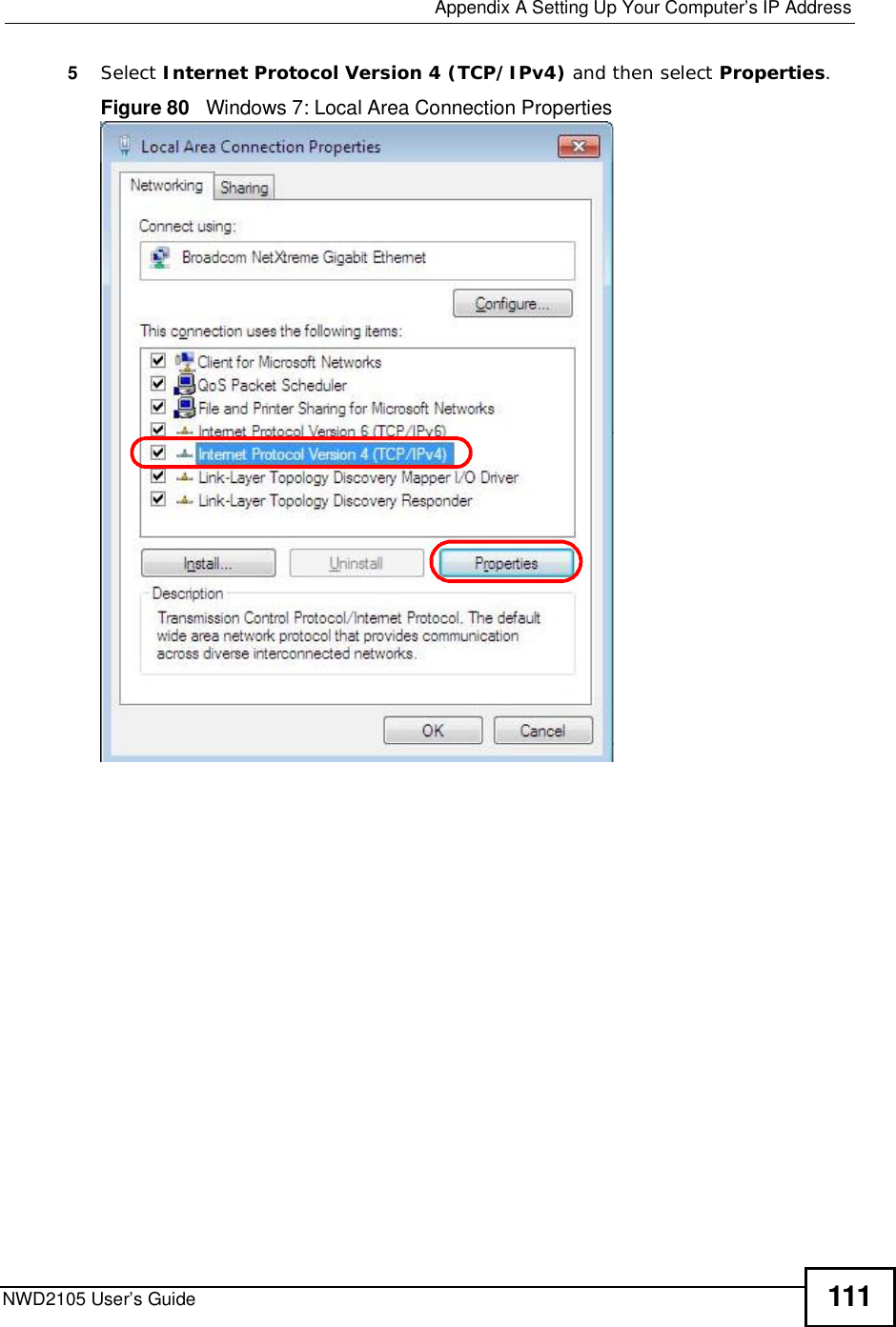
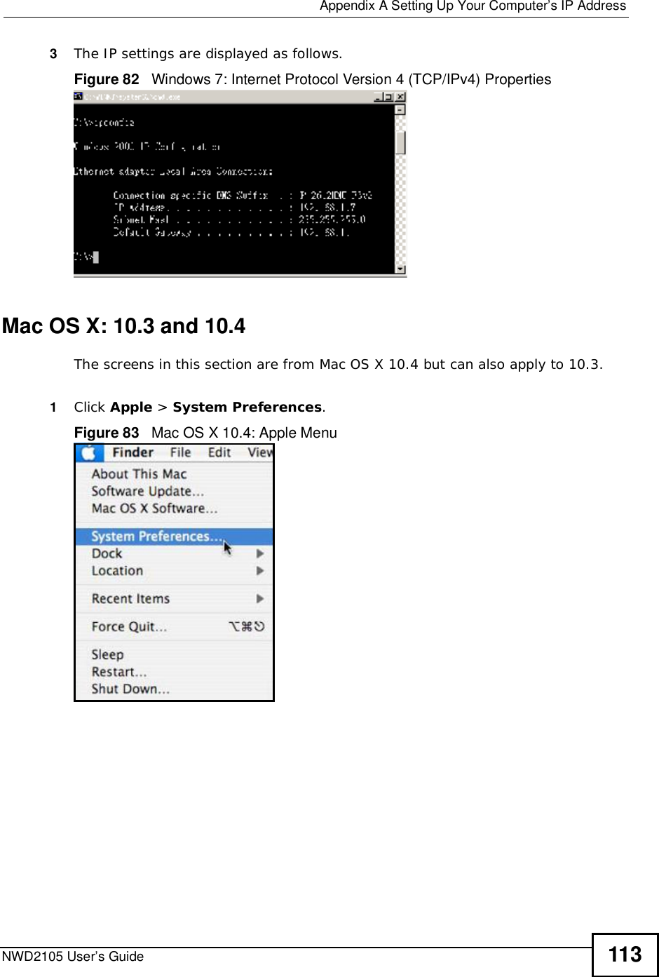
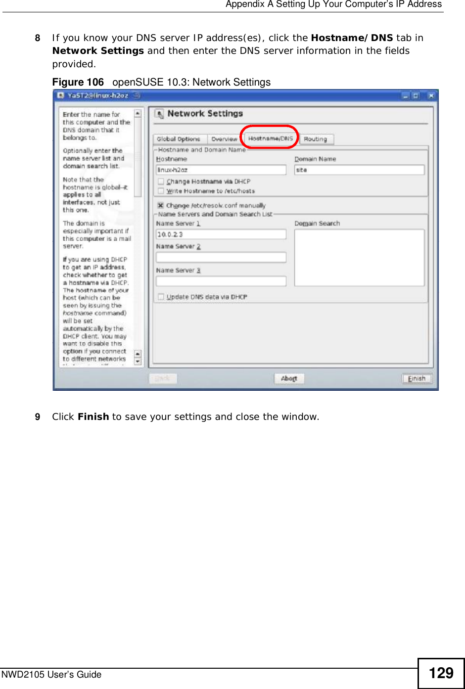
![Appendix ASetting Up Your Computer’s IP AddressNWD2105 User’s Guide1126The Internet Protocol Version 4 (TCP/IPv4) Properties window opens.Figure 81 Windows 7: Internet Protocol Version 4 (TCP/IPv4) Properties7Select Obtain an IP address automatically if your network administrator or ISP assigns your IP address dynamically.Select Use the following IP Address and fill in the IP address,Subnet mask,and Default gateway fields if you have a static IP address that was assigned to you by your network administrator or ISP. You may also have to enter a Preferred DNS server and an AlternateDNS server, if that information was provided. Click Advanced if you want to configure advanced settings for IP, DNS and WINS. 8Click OK to close the Internet Protocol (TCP/IP) Properties window.9Click OK to close the Local Area Connection Properties window.Verifying Settings1Click Start > All Programs > Accessories > Command Prompt.2In the Command Prompt window, type "ipconfig" and then press [ENTER].](https://usermanual.wiki/ZyXEL-Communications/NWD2105.UserMan-2-I88NWD2105/User-Guide-1289605-Page-2.png)