ZyXEL Communications NWD2105 Wireless N-lite USB Adapter User Manual NWD2105 0531
ZyXEL Communications Corporation Wireless N-lite USB Adapter NWD2105 0531
Contents
- 1. UserMan-1_I88NWD2105
- 2. UserMan-2_I88NWD2105
UserMan-2_I88NWD2105
Appendix ASetting Up Your Computer’s IP Address
NWD2105 User’s Guide 111
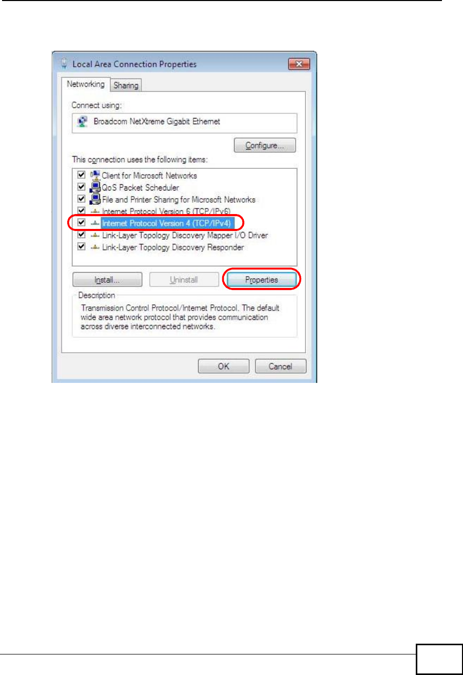
5Select Internet Protocol Version 4 (TCP/IPv4) and then select Properties.
Figure 80 Windows 7: Local Area Connection Properties
Appendix ASetting Up Your Computer’s IP Address
NWD2105 User’s Guide
112
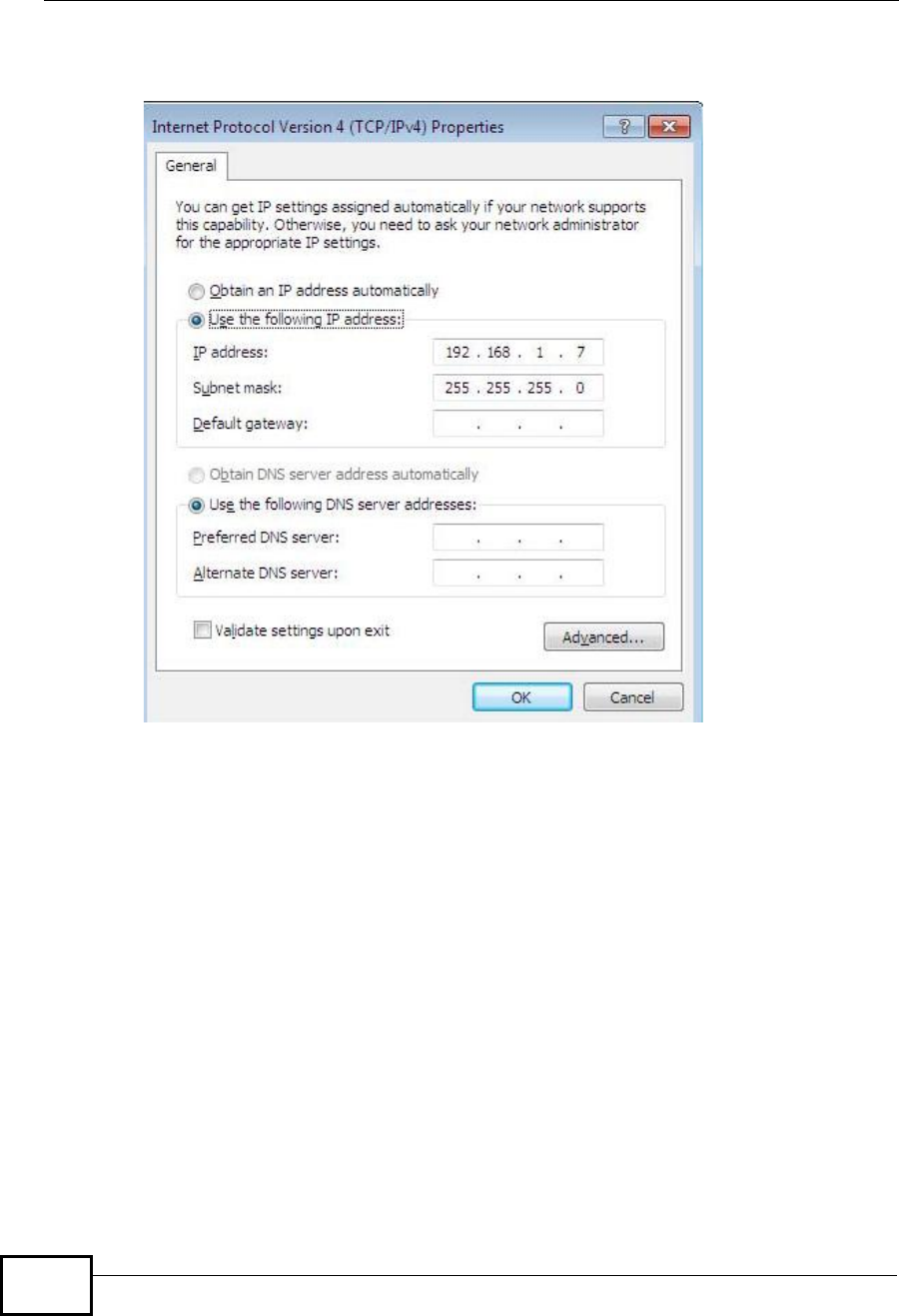
6The Internet Protocol Version 4 (TCP/IPv4) Properties window opens.
Figure 81 Windows 7: Internet Protocol Version 4 (TCP/IPv4) Properties
7Select Obtain an IP address automatically if your network administrator or ISP
assigns your IP address dynamically.
Select Use the following IP Address and fill in the IP address,Subnet mask,
and Default gateway fields if you have a static IP address that was assigned to
you by your network administrator or ISP. You may also have to enter a Preferred
DNS server and an AlternateDNS server, if that information was provided.
Click Advanced if you want to configure advanced settings for IP, DNS and WINS.
8Click OK to close the Internet Protocol (TCP/IP) Properties window.
9Click OK to close the Local Area Connection Properties window.
Verifying Settings
1Click Start > All Programs > Accessories > Command Prompt.
2In the Command Prompt window, type "ipconfig" and then press [ENTER].
Appendix ASetting Up Your Computer’s IP Address
NWD2105 User’s Guide 113
3The IP settings are displayed as follows.
Figure 82 Windows 7: Internet Protocol Version 4 (TCP/IPv4) Properties
Mac OS X: 10.3 and 10.4
The screens in this section are from Mac OS X 10.4 but can also apply to 10.3.
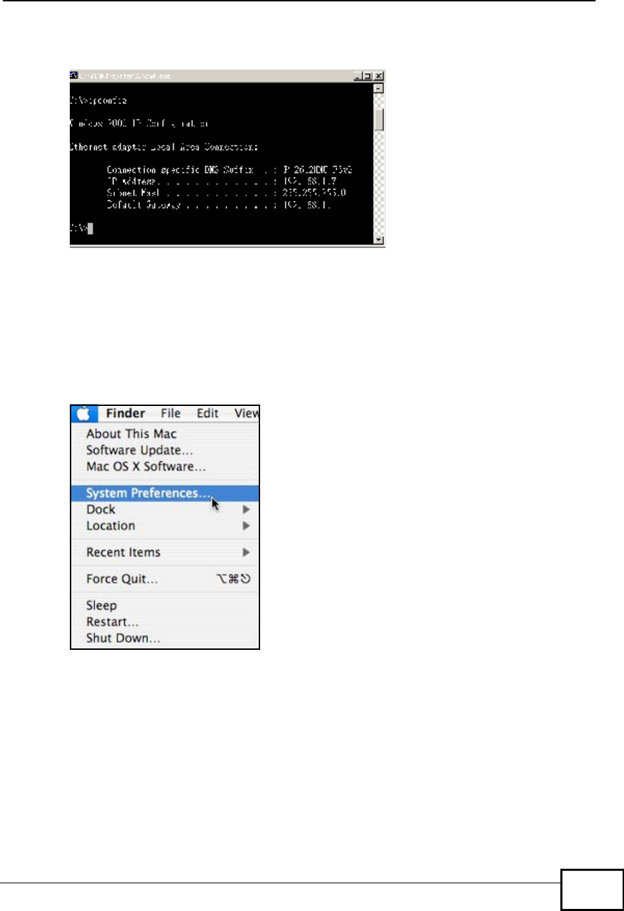
1Click Apple > System Preferences.
Figure 83 Mac OS X 10.4: Apple Menu
Appendix ASetting Up Your Computer’s IP Address
NWD2105 User’s Guide
114
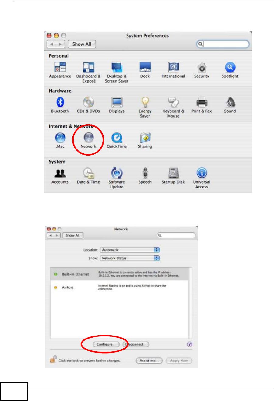
2In the System Preferences window, click the Network icon.
Figure 84 Mac OS X 10.4: System Preferences
3When the Network preferences pane opens, select Built-in Ethernet from the
network connection type list, and then click Configure.
Figure 85 Mac OS X 10.4: Network Preferences
Appendix ASetting Up Your Computer’s IP Address
NWD2105 User’s Guide 115
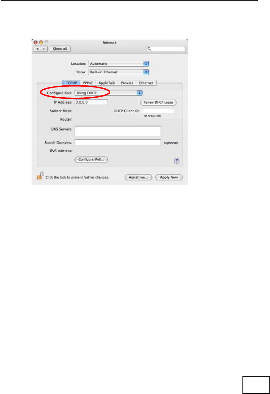
4For dynamically assigned settings, select Using DHCP from the Configure IPv4
list in the TCP/IP tab.
Figure 86 Mac OS X 10.4: Network Preferences > TCP/IP Tab.
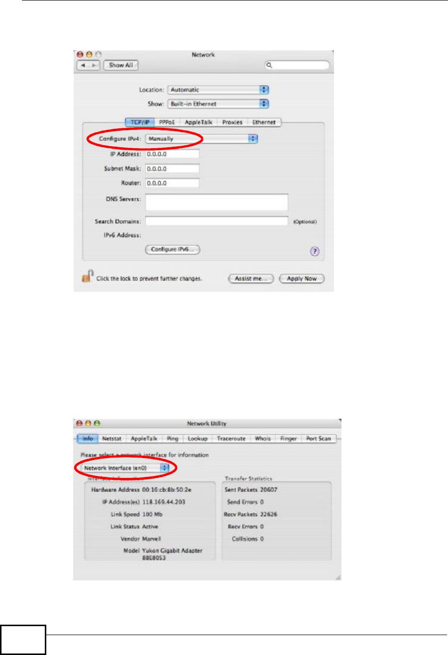
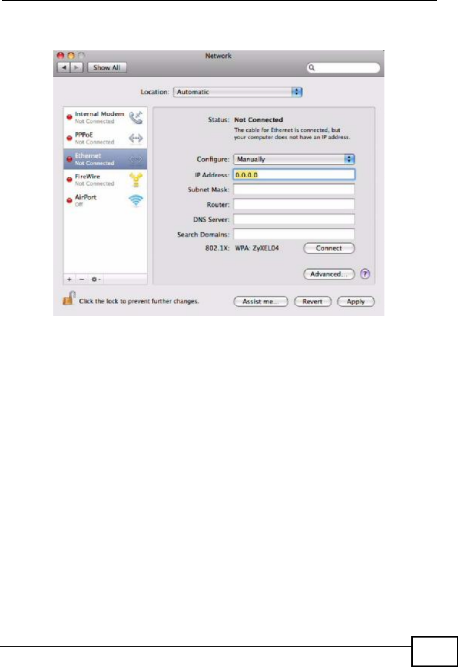
5For statically assigned settings, do the following:
•From the Configure IPv4 list, select Manually.
•In the IP Address field, type your IP address.
•In the Subnet Mask field, type your subnet mask.
Appendix ASetting Up Your Computer’s IP Address
NWD2105 User’s Guide
116
•In the Router field, type the IP address of your device.
Figure 87 Mac OS X 10.4: Network Preferences > Ethernet
6Click Apply Now and close the window.
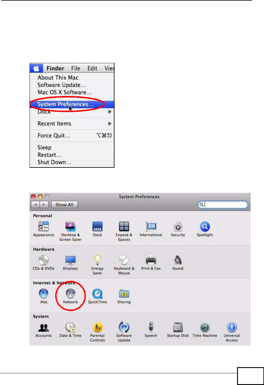
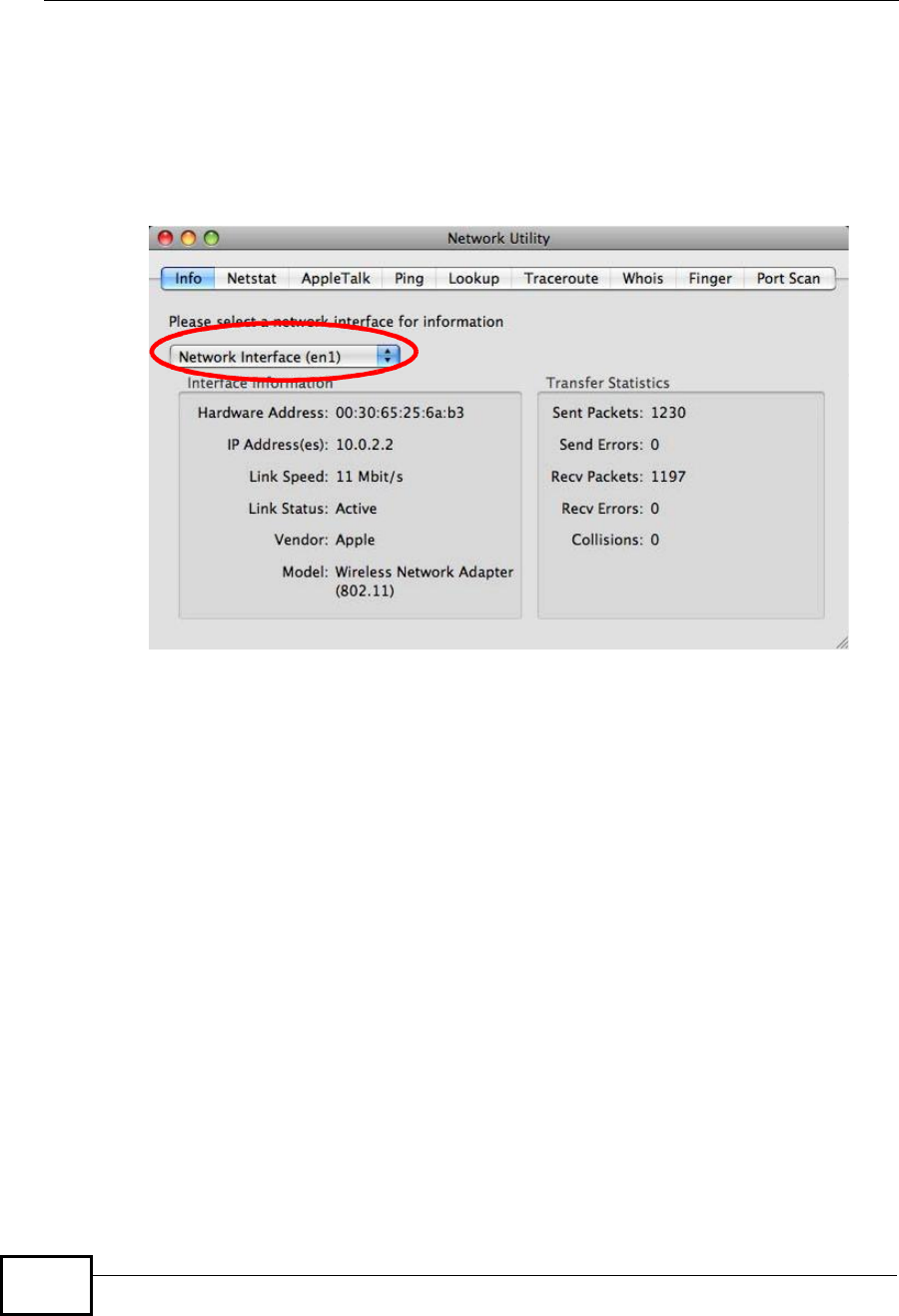
Verifying Settings
Check your TCP/IP properties by clicking Applications > Utilities > Network
Utilities, and then selecting the appropriate Network Interface from the Info
tab.
Figure 88 Mac OS X 10.4: Network Utility
Appendix ASetting Up Your Computer’s IP Address
NWD2105 User’s Guide 117
Mac OS X: 10.5 and 10.6
The screens in this section are from Mac OS X 10.5 but can also apply to 10.6.
1Click Apple > System Preferences.
Figure 89 Mac OS X 10.5: Apple Menu
2In System Preferences, click the Network icon.
Figure 90 Mac OS X 10.5: Systems Preferences
Appendix ASetting Up Your Computer’s IP Address
NWD2105 User’s Guide
118
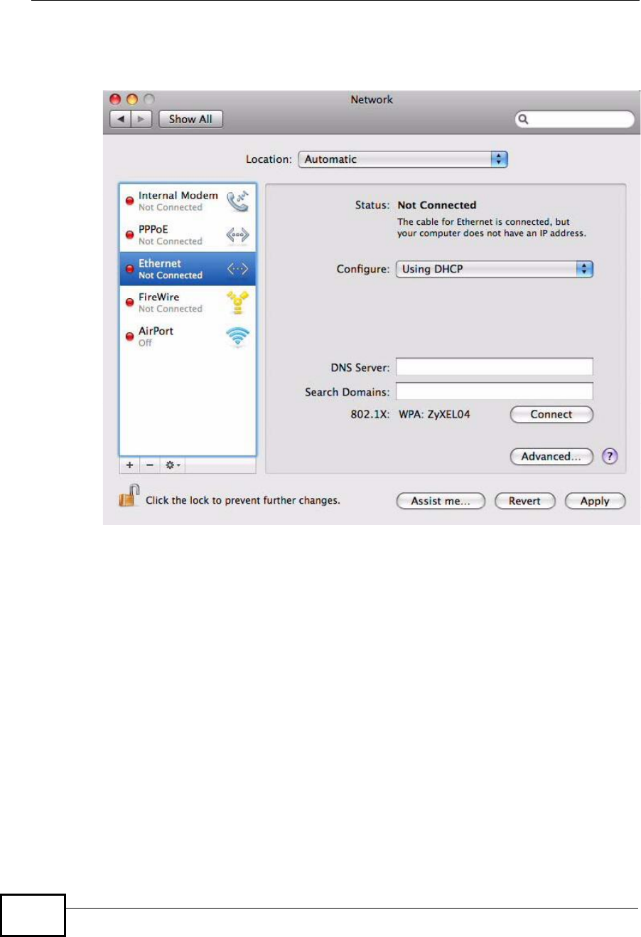
3When the Network preferences pane opens, select Ethernet from the list of
available connection types.
Figure 91 Mac OS X 10.5: Network Preferences > Ethernet
4From the Configure list, select Using DHCP for dynamically assigned settings.
5For statically assigned settings, do the following:
•From the Configure list, select Manually.
•In the IP Address field, enter your IP address.
•In the Subnet Mask field, enter your subnet mask.
Appendix ASetting Up Your Computer’s IP Address
NWD2105 User’s Guide 119
•In the Router field, enter the IP address of your NWD2105.
Figure 92 Mac OS X 10.5: Network Preferences > Ethernet
6Click Apply and close the window.
Appendix ASetting Up Your Computer’s IP Address
NWD2105 User’s Guide
120
Verifying Settings
Check your TCP/IP properties by clicking Applications > Utilities > Network
Utilities, and then selecting the appropriate Network interface from the Info
tab.
Figure 93 Mac OS X 10.5: Network Utility
Linux: Ubuntu 8 (GNOME)
This section shows you how to configure your computer’s TCP/IP settings in the
GNU Object Model Environment (GNOME) using the Ubuntu 8 Linux distribution.
The procedure, screens and file locations may vary depending on your specific
distribution, release version, and individual configuration. The following screens
use the default Ubuntu 8 installation.
Note: Make sure you are logged in as the root administrator.
Follow the steps below to configure your computer IP address in GNOME:
Appendix ASetting Up Your Computer’s IP Address
NWD2105 User’s Guide 121
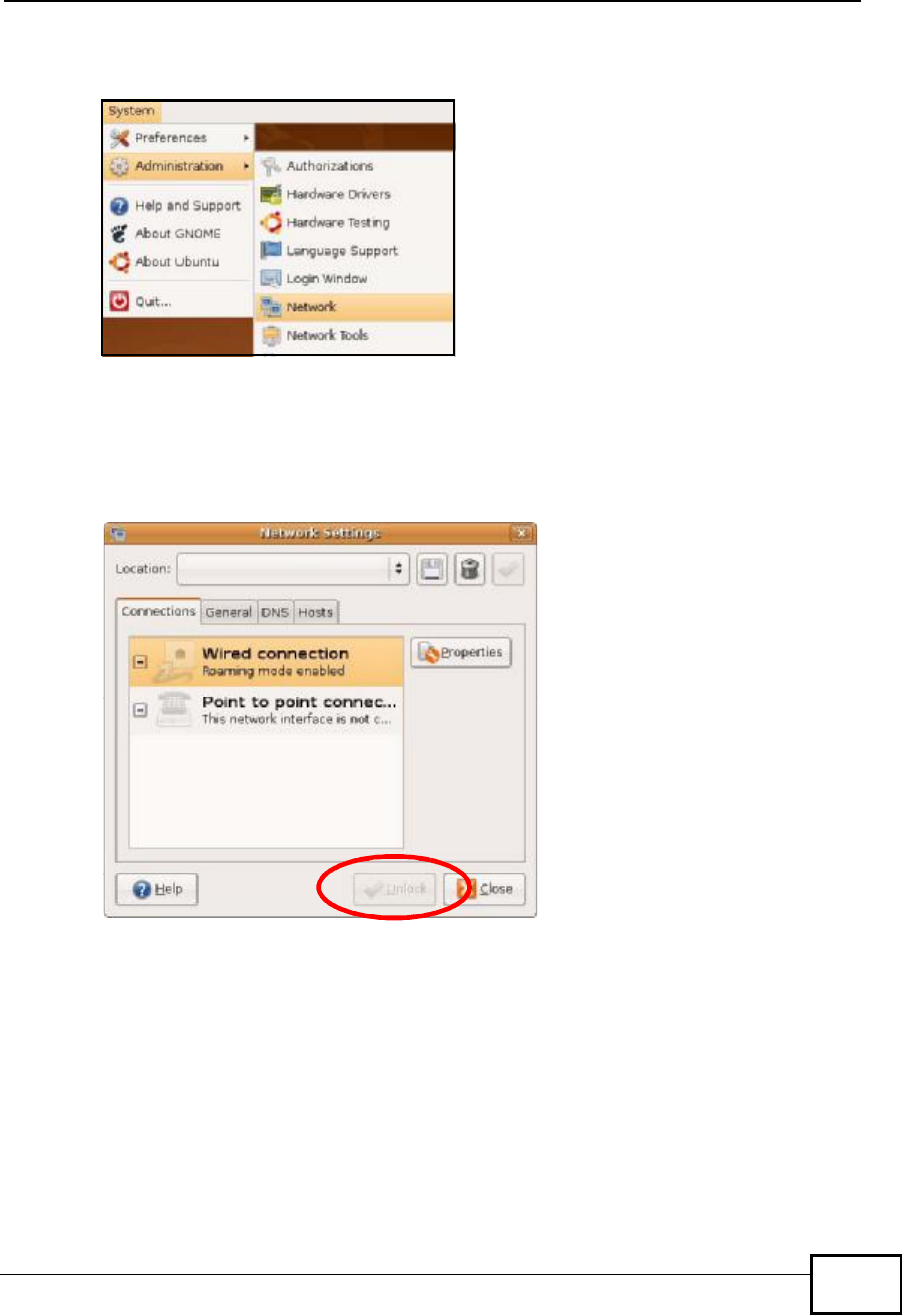
1Click System > Administration > Network.
Figure 94 Ubuntu 8: System > Administration Menu
2When the Network Settings window opens, click Unlock to open the
Authenticate window. (By default, the Unlock button is greyed out until clicked.)
You cannot make changes to your configuration unless you first enter your admin
password.
Figure 95 Ubuntu 8: Network Settings > Connections
Appendix ASetting Up Your Computer’s IP Address
NWD2105 User’s Guide
122
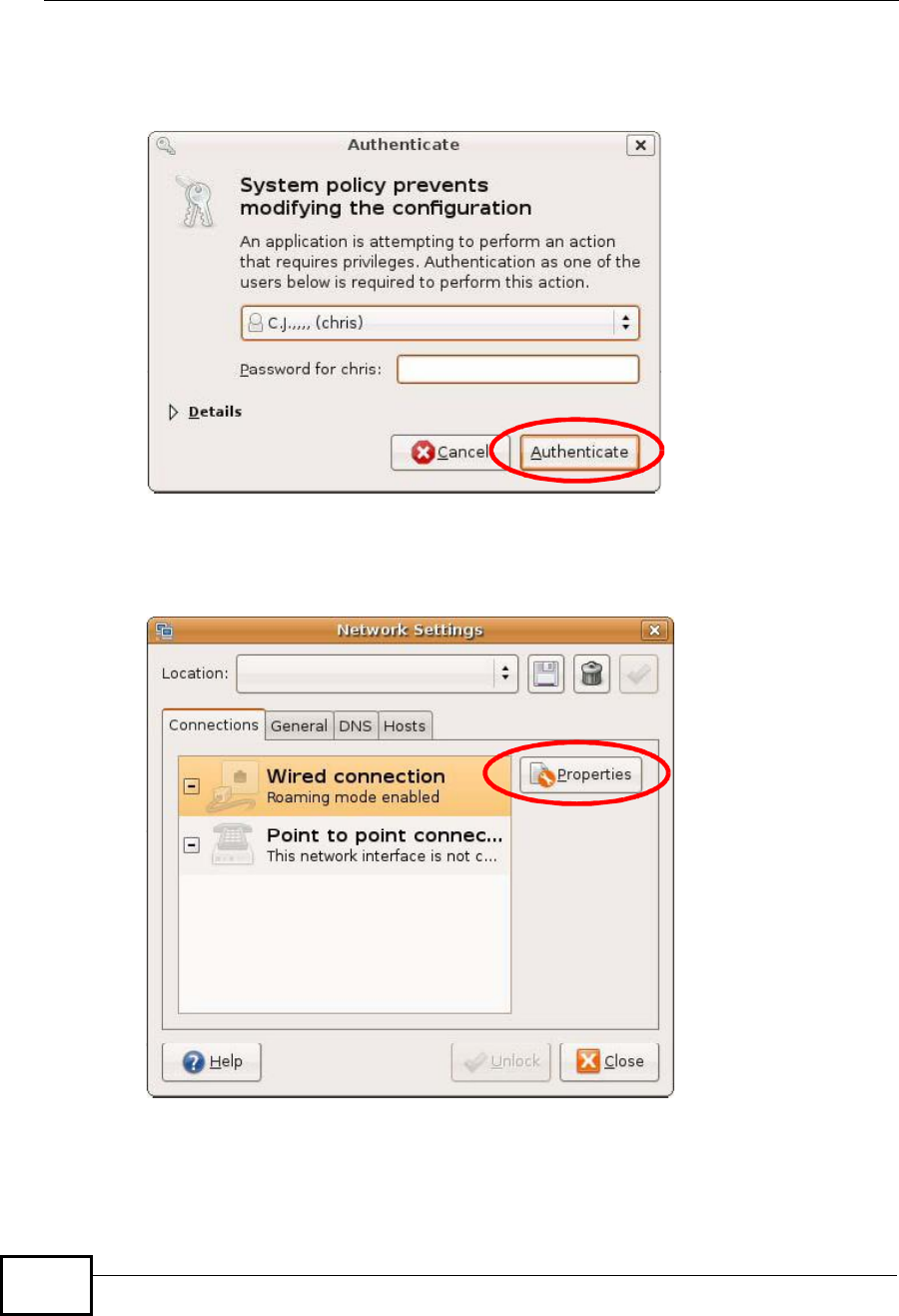
3In the Authenticate window, enter your admin account name and password then
click the Authenticate button.
Figure 96 Ubuntu 8: Administrator Account Authentication
4In the Network Settings window, select the connection that you want to
configure, then click Properties.
Figure 97 Ubuntu 8: Network Settings > Connections
Appendix ASetting Up Your Computer’s IP Address
NWD2105 User’s Guide 123
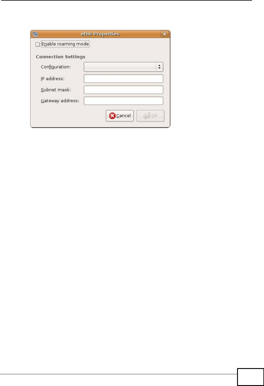
5The Properties dialog box opens.
Figure 98 Ubuntu 8: Network Settings > Properties
•In the Configuration list, select Automatic Configuration (DHCP) if you
have a dynamic IP address.
•In the Configuration list, select Static IP address if you have a static IP
address. Fill in the IP address,Subnet mask, and Gateway address fields.
6Click OK to save the changes and close the Properties dialog box and return to
the Network Settings screen.
Appendix ASetting Up Your Computer’s IP Address
NWD2105 User’s Guide
124
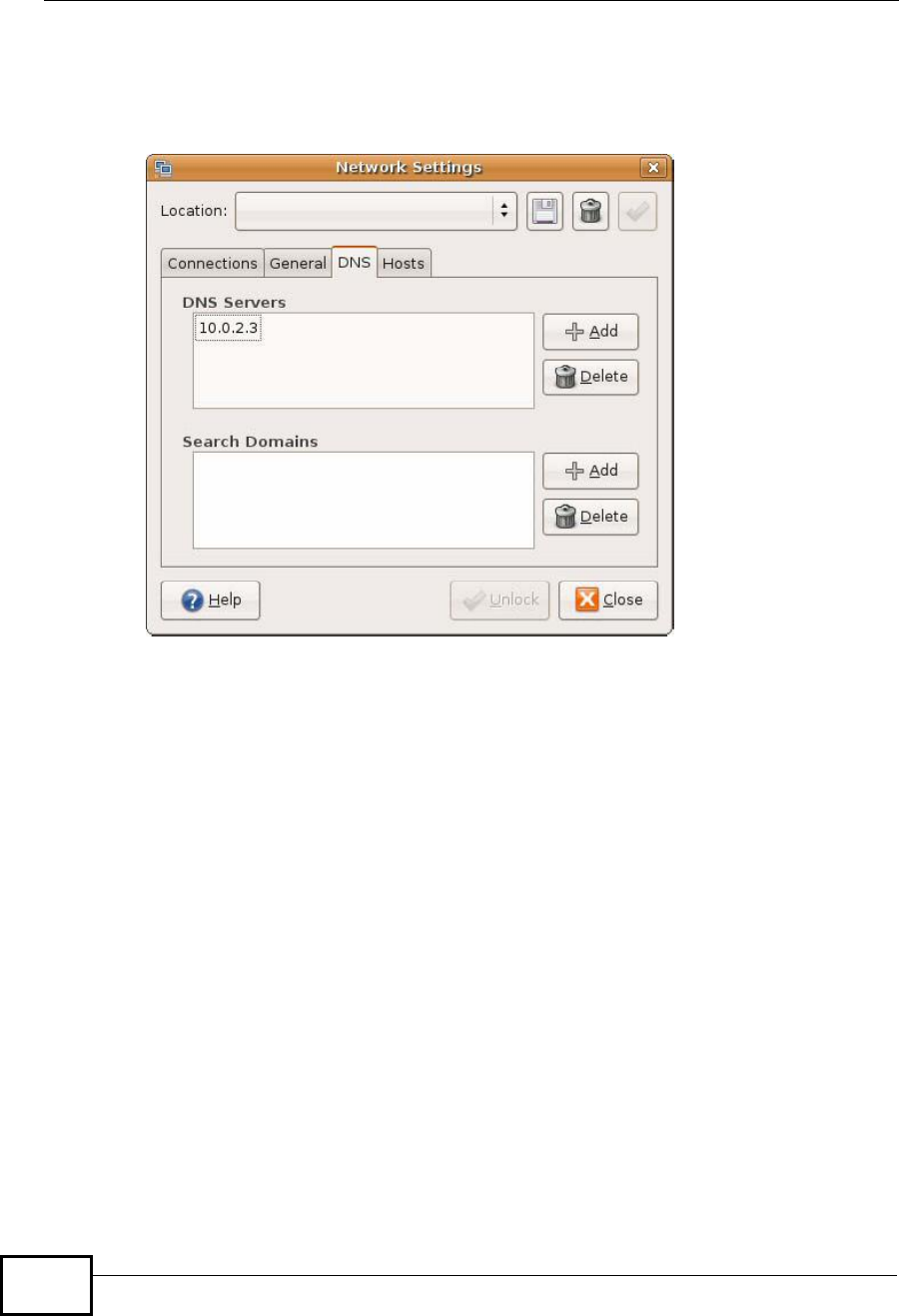
7If you know your DNS server IP address(es), click the DNS tab in the Network
Settings window and then enter the DNS server information in the fields
provided.
Figure 99 Ubuntu 8: Network Settings > DNS
8Click the Close button to apply the changes.
Verifying Settings
Check your TCP/IP properties by clicking System > Administration > Network
Tools, and then selecting the appropriate Network device from the Devices
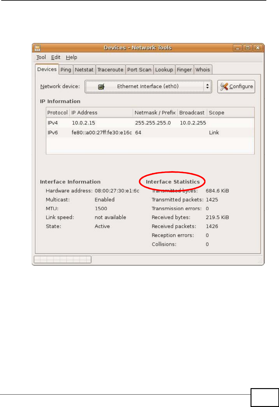
Appendix ASetting Up Your Computer’s IP Address
NWD2105 User’s Guide 125
tab. The Interface Statistics column shows data if your connection is working
properly.
Figure 100 Ubuntu 8: Network Tools
Linux: openSUSE 10.3 (KDE)
This section shows you how to configure your computer’s TCP/IP settings in the K
Desktop Environment (KDE) using the openSUSE 10.3 Linux distribution. The
procedure, screens and file locations may vary depending on your specific
distribution, release version, and individual configuration. The following screens
use the default openSUSE 10.3 installation.
Note: Make sure you are logged in as the root administrator.
Follow the steps below to configure your computer IP address in the KDE:
Appendix ASetting Up Your Computer’s IP Address
NWD2105 User’s Guide
126
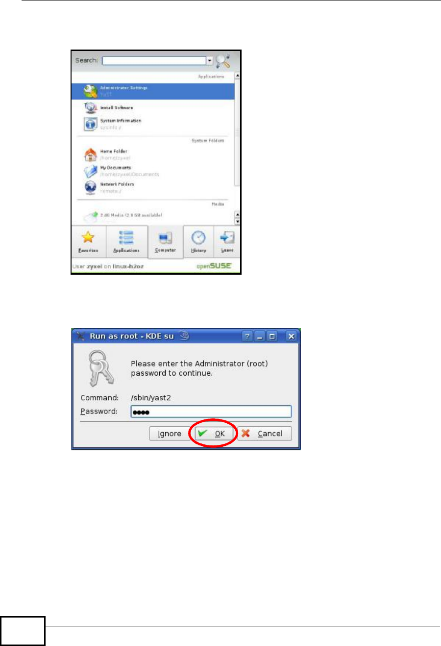
1Click K Menu > Computer > Administrator Settings (YaST).
Figure 101 openSUSE 10.3: K Menu > Computer Menu
2When the Run as Root - KDE su dialog opens, enter the admin password and
click OK.
Figure 102 openSUSE 10.3: K Menu > Computer Menu
Appendix ASetting Up Your Computer’s IP Address
NWD2105 User’s Guide 127
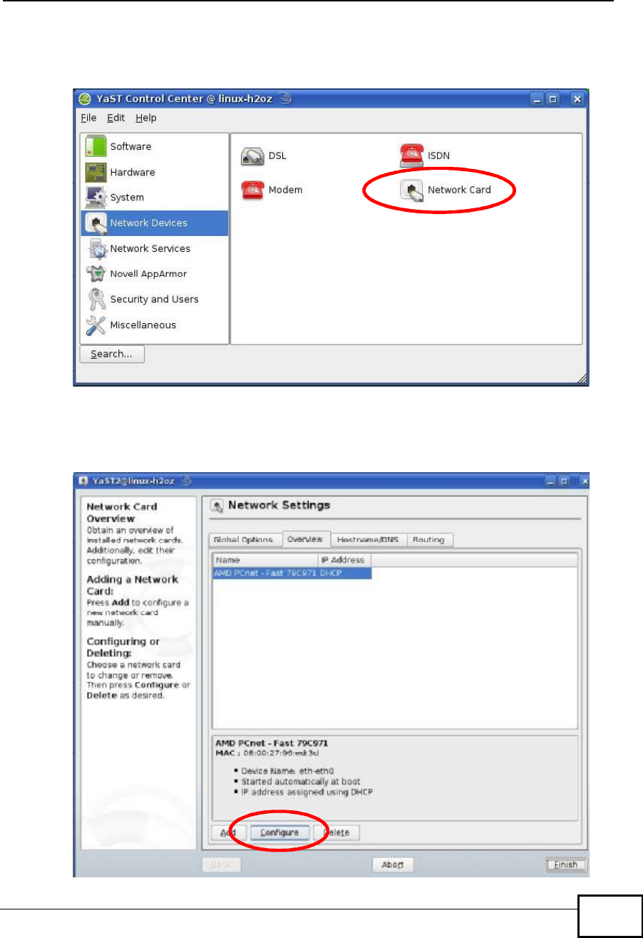
3When the YaST Control Center window opens, select Network Devices and
then click the Network Card icon.
Figure 103 openSUSE 10.3: YaST Control Center
4When the Network Settings window opens, click the Overview tab, select the
appropriate connection Name from the list, and then click the Configure button.
Figure 104 openSUSE 10.3: Network Settings
Appendix ASetting Up Your Computer’s IP Address
NWD2105 User’s Guide
128
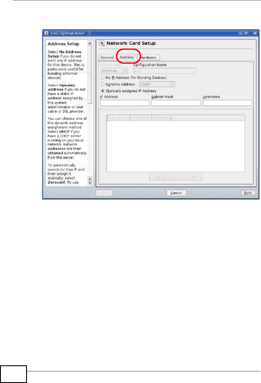
5When the Network Card Setup window opens, click the Address tab
Figure 105 openSUSE 10.3: Network Card Setup
6Select Dynamic Address (DHCP) if you have a dynamic IP address.
Select Statically assigned IP Address if you have a static IP address. Fill in the
IP address,Subnet mask, and Hostname fields.
7Click Next to save the changes and close the Network Card Setup window.
Appendix ASetting Up Your Computer’s IP Address
NWD2105 User’s Guide 129
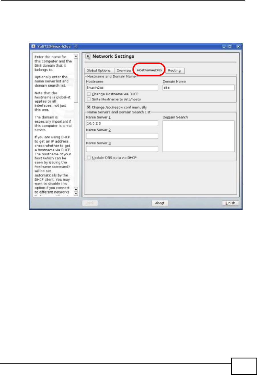
8If you know your DNS server IP address(es), click the Hostname/DNS tab in
Network Settings and then enter the DNS server information in the fields
provided.
Figure 106 openSUSE 10.3: Network Settings
9Click Finish to save your settings and close the window.
Appendix ASetting Up Your Computer’s IP Address
NWD2105 User’s Guide
130
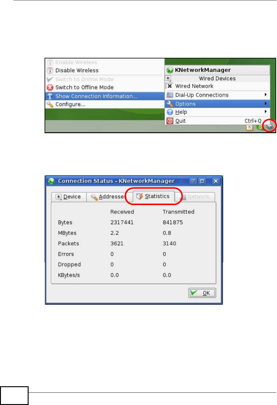
Verifying Settings
Click the KNetwork Manager icon on the Task bar to check your TCP/IP
properties. From the Options sub-menu, select Show Connection Information.
Figure 107 openSUSE 10.3: KNetwork Manager
When the Connection Status - KNetwork Manager window opens, click the
Statistics tab to see if your connection is working properly.
Figure 108 openSUSE: Connection Status - KNetwork Manager
NWD2105 User’s Guide 131
APPENDIX B
Wireless LANs
Wireless LAN Topologies
This section discusses ad-hoc and infrastructure wireless LAN topologies.
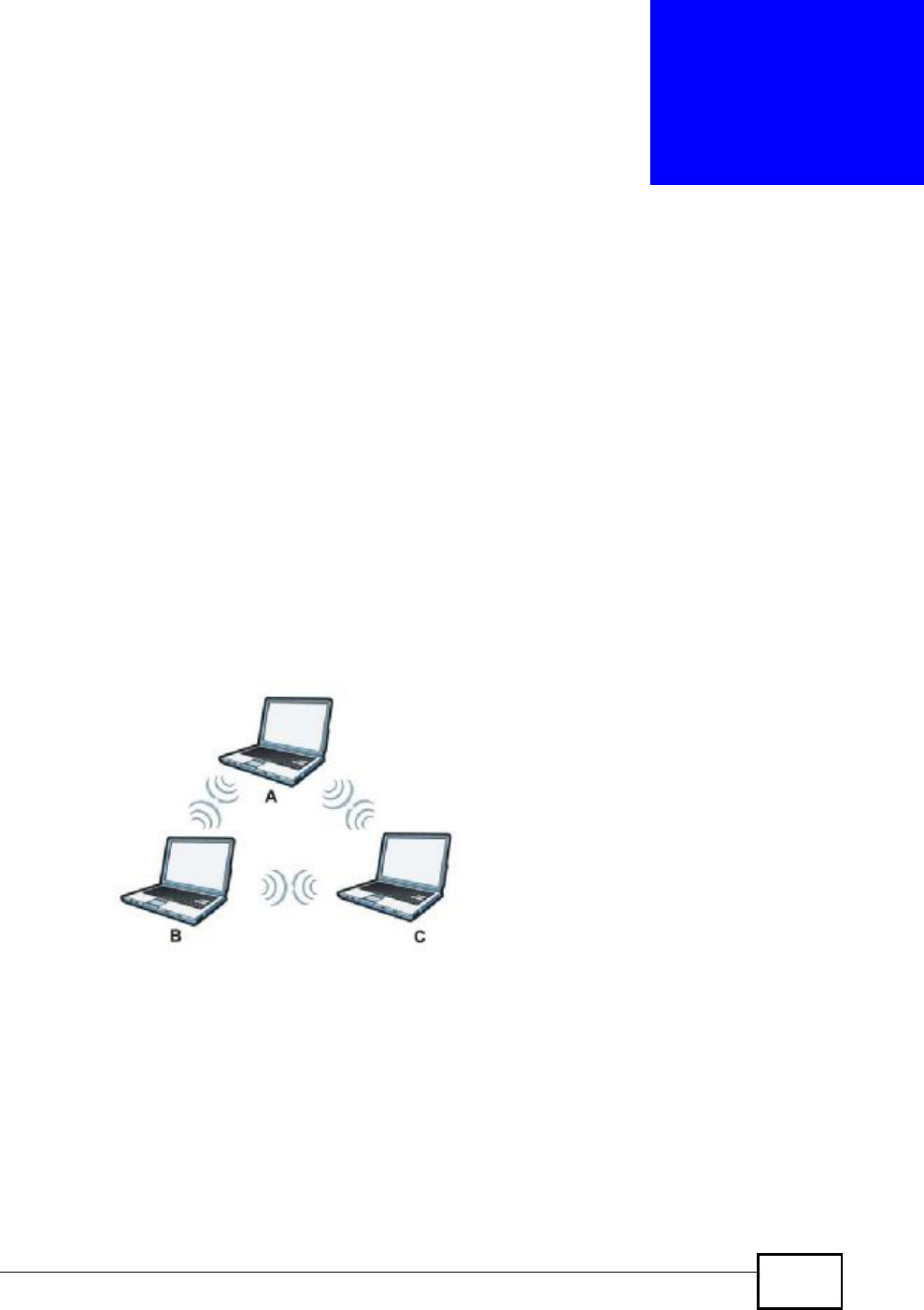
Ad-hoc Wireless LAN Configuration
The simplest WLAN configuration is an independent (Ad-hoc) WLAN that connects
a set of computers with wireless adapters (A, B, C). Any time two or more wireless
adapters are within range of each other, they can set up an independent network,
which is commonly referred to as an ad-hoc network or Independent Basic Service
Set (IBSS). The following diagram shows an example of notebook computers
using wireless adapters to form an ad-hoc wireless LAN.
Figure 109 Peer-to-Peer Communication in an Ad-hoc Network
BSS
A Basic Service Set (BSS) exists when all communications between wireless
clients or between a wireless client and a wired network client go through one
access point (AP).
Intra-BSS traffic is traffic between wireless clients in the BSS. When Intra-BSS is
enabled, wireless client A and B can access the wired network and communicate
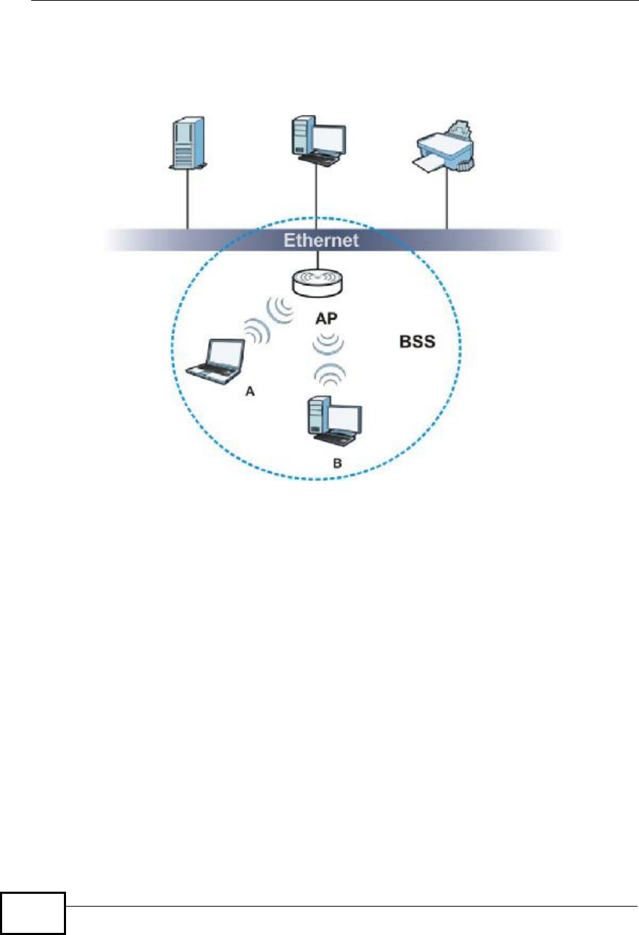
Appendix BWireless LANs
NWD2105 User’s Guide
132
with each other. When Intra-BSS is disabled, wireless client A and B can still
access the wired network but cannot communicate with each other.
Figure 110 Basic Service Set
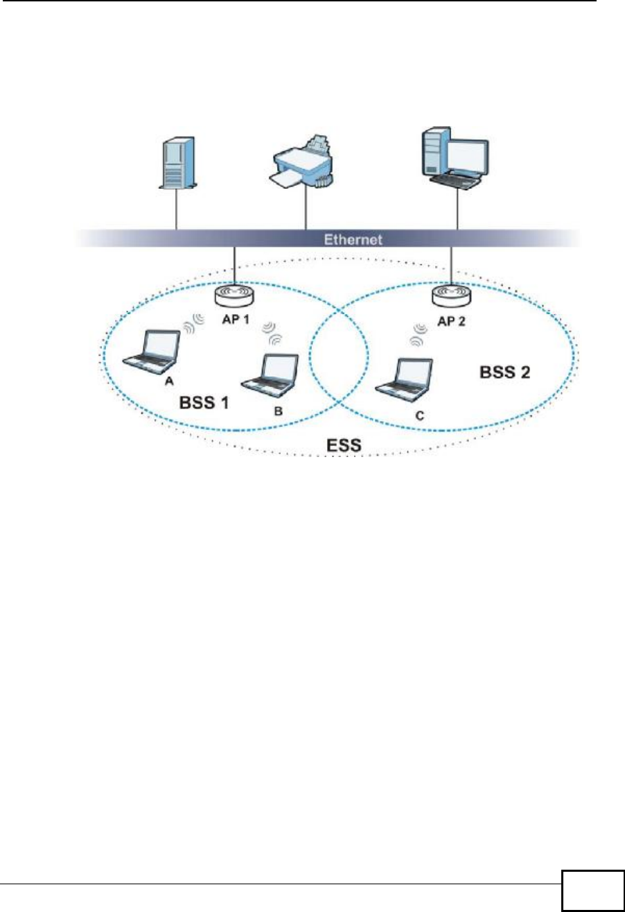
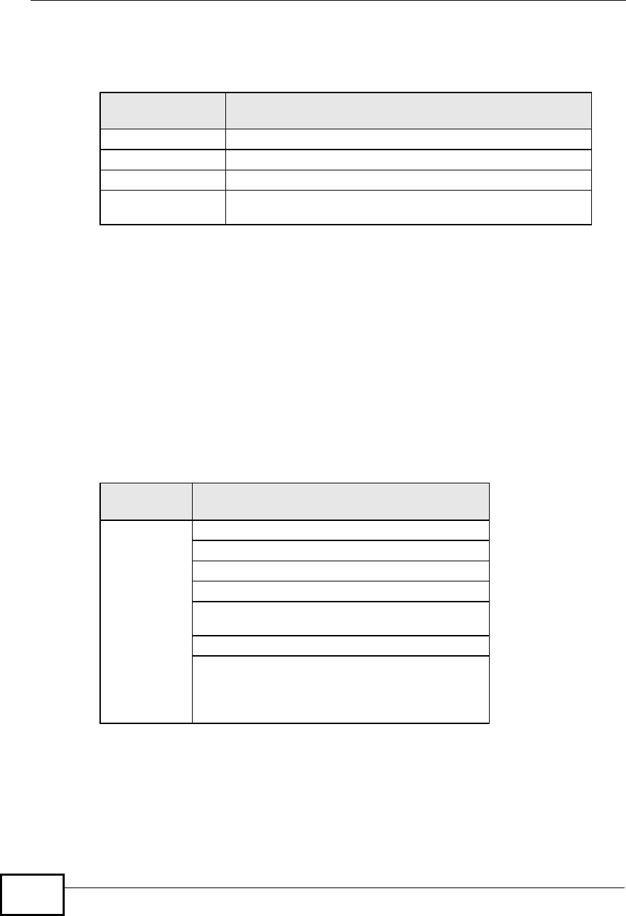
ESS
An Extended Service Set (ESS) consists of a series of overlapping BSSs, each
containing an access point, with each access point connected together by a wired
network. This wired connection between APs is called a Distribution System (DS).
This type of wireless LAN topology is called an Infrastructure WLAN. The Access
Points not only provide communication with the wired network but also mediate
wireless network traffic in the immediate neighborhood.
Appendix BWireless LANs
NWD2105 User’s Guide 133
An ESSID (ESS IDentification) uniquely identifies each ESS. All access points and
their associated wireless clients within the same ESS must have the same ESSID
in order to communicate.
Figure 111 Infrastructure WLAN
Channel
A channel is the radio frequency(ies) used by wireless devices to transmit and
receive data. Channels available depend on your geographical area. You may have
a choice of channels (for your region) so you should use a channel different from
an adjacent AP (access point) to reduce interference. Interference occurs when
radio signals from different access points overlap causing interference and
degrading performance.
Adjacent channels partially overlap however. To avoid interference due to overlap,
your AP should be on a channel at least five channels away from a channel that an
adjacent AP is using. For example, if your region has 11 channels and an adjacent
AP is using channel 1, then you need to select a channel between 6 or 11.
RTS/CTS
A hidden node occurs when two stations are within range of the same access
point, but are not within range of each other. The following figure illustrates a
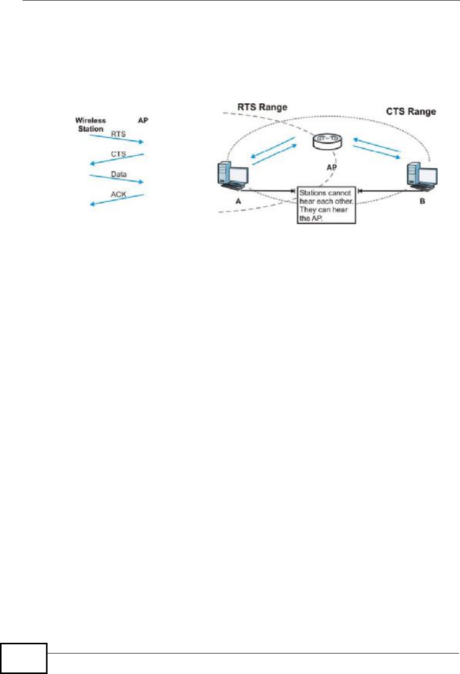
Appendix BWireless LANs
NWD2105 User’s Guide
134
hidden node. Both stations (STA) are within range of the access point (AP) or
wireless gateway, but out-of-range of each other, so they cannot "hear" each
other, that is they do not know if the channel is currently being used. Therefore,
they are considered hidden from each other.
Figure 112 RTS/CTS
When station A sends data to the AP, it might not know that the station B is
already using the channel. If these two stations send data at the same time,
collisions may occur when both sets of data arrive at the AP at the same time,
resulting in a loss of messages for both stations.
RTS/CTS is designed to prevent collisions due to hidden nodes. An RTS/CTS
defines the biggest size data frame you can send before an RTS (Request To
Send)/CTS (Clear to Send) handshake is invoked.
When a data frame exceeds the RTS/CTS value you set (between 0 to 2432
bytes), the station that wants to transmit this frame must first send an RTS
(Request To Send) message to the AP for permission to send it. The AP then
responds with a CTS (Clear to Send) message to all other stations within its range
to notify them to defer their transmission. It also reserves and confirms with the
requesting station the time frame for the requested transmission.
Stations can send frames smaller than the specified RTS/CTS directly to the AP
without the RTS (Request To Send)/CTS (Clear to Send) handshake.
You should only configure RTS/CTS if the possibility of hidden nodes exists on
your network and the "cost" of resending large frames is more than the extra
network overhead involved in the RTS (Request To Send)/CTS (Clear to Send)
handshake.
If the RTS/CTS value is greater than the Fragmentation Threshold value (see
next), then the RTS (Request To Send)/CTS (Clear to Send) handshake will never
occur as data frames will be fragmented before they reach RTS/CTS size.
Note: Enabling the RTS Threshold causes redundant network overhead that could
negatively affect the throughput performance instead of providing a remedy.

Appendix BWireless LANs
NWD2105 User’s Guide 135
Fragmentation Threshold
AFragmentation Threshold is the maximum data fragment size (between 256
and 2432 bytes) that can be sent in the wireless network before the AP will
fragment the packet into smaller data frames.
A large Fragmentation Threshold is recommended for networks not prone to
interference while you should set a smaller threshold for busy networks or
networks that are prone to interference.
If the Fragmentation Threshold value is smaller than the RTS/CTS value (see
previously) you set then the RTS (Request To Send)/CTS (Clear to Send)
handshake will never occur as data frames will be fragmented before they reach
RTS/CTS size.
Preamble Type
Preamble is used to signal that data is coming to the receiver. Short and long refer
to the length of the synchronization field in a packet.
Short preamble increases performance as less time sending preamble means
more time for sending data. All IEEE 802.11 compliant wireless adapters support
long preamble, but not all support short preamble.
Use long preamble if you are unsure what preamble mode other wireless devices
on the network support, and to provide more reliable communications in busy
wireless networks.
Use short preamble if you are sure all wireless devices on the network support it,
and to provide more efficient communications.
Use the dynamic setting to automatically use short preamble when all wireless
devices on the network support it, otherwise the NWD2105 uses long preamble.
Note: The wireless devices MUSTuse the same preamble mode in order to
communicate.
IEEE 802.11g Wireless LAN
IEEE 802.11g is fully compatible with the IEEE 802.11b standard. This means an
IEEE 802.11b adapter can interface directly with an IEEE 802.11g access point
(and vice versa) at 11 Mbps or lower depending on range. IEEE 802.11g has
Appendix BWireless LANs
NWD2105 User’s Guide
136
several intermediate rate steps between the maximum and minimum data rates.
The IEEE 802.11g data rate and modulation are as follows:
Wireless Security Overview
Wireless security is vital to your network to protect wireless communication
between wireless clients, access points and the wired network.
Wireless security methods available on the NWD2105 are data encryption,
wireless client authentication, restricting access by device MAC address and hiding
the NWD2105 identity.
The following figure shows the relative effectiveness of these wireless security
methods available on your NWD2105.
Note: You must enable the same wireless security settings on the NWD2105 and on
all wireless clients that you want to associate with it.
Table 28 IEEE 802.11g
DATA RATE
(MBPS) MODULATION
1DBPSK (Differential Binary Phase Shift Keyed)
2DQPSK (Differential Quadrature Phase Shift Keying)
5.5 / 11CCK (Complementary Code Keying)
6/9/12/18/24/36/
48/54 OFDM (Orthogonal Frequency Division Multiplexing)
Table 29 Wireless Security Levels
SECURITY
LEVEL SECURITY TYPE
Least
Secure
Most Secure
Unique SSID (Default)
Unique SSID with Hide SSID Enabled
MAC Address Filtering
WEP Encryption
IEEE802.1x EAP with RADIUS Server
Authentication
Wi-Fi Protected Access (WPA)
WPA2

Appendix BWireless LANs
NWD2105 User’s Guide 137
IEEE 802.1x
In June 2001, the IEEE 802.1x standard was designed to extend the features of
IEEE 802.11 to support extended authentication as well as providing additional
accounting and control features. It is supported by Windows XP and a number of
network devices. Some advantages of IEEE 802.1x are:
•User based identification that allows for roaming.
•Support for RADIUS (Remote Authentication Dial In User Service, RFC 2138,
2139) for centralized user profile and accounting management on a network
RADIUS server.
•Support for EAP (Extensible Authentication Protocol, RFC 2486) that allows
additional authentication methods to be deployed with no changes to the access
point or the wireless clients.
RADIUS
RADIUS is based on a client-server model that supports authentication,
authorization and accounting. The access point is the client and the server is the
RADIUS server. The RADIUS server handles the following tasks:
•Authentication
Determines the identity of the users.
•Authorization
Determines the network services available to authenticated users once they are
connected to the network.
•Accounting
Keeps track of the client’s network activity.
RADIUS is a simple package exchange in which your AP acts as a message relay
between the wireless client and the network RADIUS server.
Types of RADIUS Messages
The following types of RADIUS messages are exchanged between the access point
and the RADIUS server for user authentication:
•Access-Request
Sent by an access point requesting authentication.
•Access-Reject
Sent by a RADIUS server rejecting access.
•Access-Accept
Sent by a RADIUS server allowing access.

Appendix BWireless LANs
NWD2105 User’s Guide
138
•Access-Challenge
Sent by a RADIUS server requesting more information in order to allow access.
The access point sends a proper response from the user and then sends another
Access-Request message.
The following types of RADIUS messages are exchanged between the access point
and the RADIUS server for user accounting:
•Accounting-Request
Sent by the access point requesting accounting.
•Accounting-Response
Sent by the RADIUS server to indicate that it has started or stopped accounting.
In order to ensure network security, the access point and the RADIUS server use a
shared secret key, which is a password, they both know. The key is not sent over
the network. In addition to the shared key, password information exchanged is
also encrypted to protect the network from unauthorized access.
Types of EAP Authentication
This section discusses some popular authentication types: EAP-MD5, EAP-TLS,
EAP-TTLS, PEAP and LEAP. Your wireless LAN device may not support all
authentication types.
EAP (Extensible Authentication Protocol) is an authentication protocol that runs on
top of the IEEE 802.1x transport mechanism in order to support multiple types of
user authentication. By using EAP to interact with an EAP-compatible RADIUS
server, an access point helps a wireless station and a RADIUS server perform
authentication.
The type of authentication you use depends on the RADIUS server and an
intermediary AP(s) that supports IEEE 802.1x. .
For EAP-TLS authentication type, you must first have a wired connection to the
network and obtain the certificate(s) from a certificate authority (CA). A certificate
(also called digital IDs) can be used to authenticate users and a CA issues
certificates and guarantees the identity of each certificate owner.
EAP-MD5 (Message-Digest Algorithm 5)
MD5 authentication is the simplest one-way authentication method. The
authentication server sends a challenge to the wireless client. The wireless client
‘proves’ that it knows the password by encrypting the password with the challenge
and sends back the information. Password is not sent in plain text.

Appendix BWireless LANs
NWD2105 User’s Guide 139
However, MD5 authentication has some weaknesses. Since the authentication
server needs to get the plaintext passwords, the passwords must be stored. Thus
someone other than the authentication server may access the password file. In
addition, it is possible to impersonate an authentication server as MD5
authentication method does not perform mutual authentication. Finally, MD5
authentication method does not support data encryption with dynamic session
key. You must configure WEP encryption keys for data encryption.
EAP-TLS (Transport Layer Security)
With EAP-TLS, digital certifications are needed by both the server and the wireless
clients for mutual authentication. The server presents a certificate to the client.
After validating the identity of the server, the client sends a different certificate to
the server. The exchange of certificates is done in the open before a secured
tunnel is created. This makes user identity vulnerable to passive attacks. A digital
certificate is an electronic ID card that authenticates the sender’s identity.
However, to implement EAP-TLS, you need a Certificate Authority (CA) to handle
certificates, which imposes a management overhead.
EAP-TTLS (Tunneled Transport Layer Service)
EAP-TTLS is an extension of the EAP-TLS authentication that uses certificates for
only the server-side authentications to establish a secure connection. Client
authentication is then done by sending username and password through the
secure connection, thus client identity is protected. For client authentication, EAP-
TTLS supports EAP methods and legacy authentication methods such as PAP,
CHAP, MS-CHAP and MS-CHAP v2.
PEAP (Protected EAP)
Like EAP-TTLS, server-side certificate authentication is used to establish a secure
connection, then use simple username and password methods through the
secured connection to authenticate the clients, thus hiding client identity.
However, PEAP only supports EAP methods, such as EAP-MD5, EAP-MSCHAPv2
and EAP-GTC (EAP-Generic Token Card), for client authentication. EAP-GTC is
implemented only by Cisco.
LEAP
LEAP (Lightweight Extensible Authentication Protocol) is a Cisco implementation of
IEEE 802.1x.

Appendix BWireless LANs
NWD2105 User’s Guide
140
Dynamic WEP Key Exchange
The AP maps a unique key that is generated with the RADIUS server. This key
expires when the wireless connection times out, disconnects or reauthentication
times out. A new WEP key is generated each time reauthentication is performed.
If this feature is enabled, it is not necessary to configure a default encryption key
in the wireless security configuration screen. You may still configure and store
keys, but they will not be used while dynamic WEP is enabled.
Note: EAP-MD5 cannot be used with Dynamic WEP Key Exchange
For added security, certificate-based authentications (EAP-TLS, EAP-TTLS and
PEAP) use dynamic keys for data encryption. They are often deployed in corporate
environments, but for public deployment, a simple user name and password pair
is more practical. The following table is a comparison of the features of
authentication types.
WPA and WPA2
Wi-Fi Protected Access (WPA) is a subset of the IEEE 802.11i standard. WPA2
(IEEE 802.11i) is a wireless security standard that defines stronger encryption,
authentication and key management than WPA.
Key differences between WPA or WPA2 and WEP are improved data encryption and
user authentication.
If both an AP and the wireless clients support WPA2 and you have an external
RADIUS server, use WPA2 for stronger data encryption. If you don't have an
external RADIUS server, you should use WPA2-PSK (WPA2-Pre-Shared Key) that
only requires a single (identical) password entered into each access point, wireless
gateway and wireless client. As long as the passwords match, a wireless client will
be granted access to a WLAN.
Table 30 Comparison of EAP Authentication Types
EAP-MD5 EAP-TLS EAP-TTLS PEAP LEAP
Mutual Authentication No Yes Yes Yes Yes
Certificate – Client No Yes Optional Optional No
Certificate – Server No Yes Yes Yes No
Dynamic Key Exchange No Yes Yes Yes Yes
Credential Integrity None Strong Strong Strong Moderate
Deployment Difficulty Easy Hard Moderate Moderate Moderate
Client Identity
Protection No No Yes Yes No

Appendix BWireless LANs
NWD2105 User’s Guide 141
If the AP or the wireless clients do not support WPA2, just use WPA or WPA-PSK
depending on whether you have an external RADIUS server or not.
Select WEP only when the AP and/or wireless clients do not support WPA or WPA2.
WEP is less secure than WPA or WPA2.
Encryption
WPA improves data encryption by using Temporal Key Integrity Protocol (TKIP),
Message Integrity Check (MIC) and IEEE 802.1x. WPA2 also uses TKIP when
required for compatibility reasons, but offers stronger encryption than TKIP with
Advanced Encryption Standard (AES) in the Counter mode with Cipher block
chaining Message authentication code Protocol (CCMP).
TKIP uses 128-bit keys that are dynamically generated and distributed by the
authentication server. AES (Advanced Encryption Standard) is a block cipher that
uses a 256-bit mathematical algorithm called Rijndael. They both include a per-
packet key mixing function, a Message Integrity Check (MIC) named Michael, an
extended initialization vector (IV) with sequencing rules, and a re-keying
mechanism.
WPA and WPA2 regularly change and rotate the encryption keys so that the same
encryption key is never used twice.
The RADIUS server distributes a Pairwise Master Key (PMK) key to the AP that
then sets up a key hierarchy and management system, using the PMK to
dynamically generate unique data encryption keys to encrypt every data packet
that is wirelessly communicated between the AP and the wireless clients. This all
happens in the background automatically.
The Message Integrity Check (MIC) is designed to prevent an attacker from
capturing data packets, altering them and resending them. The MIC provides a
strong mathematical function in which the receiver and the transmitter each
compute and then compare the MIC. If they do not match, it is assumed that the
data has been tampered with and the packet is dropped.
By generating unique data encryption keys for every data packet and by creating
an integrity checking mechanism (MIC), with TKIP and AES it is more difficult to
decrypt data on a Wi-Fi network than WEP and difficult for an intruder to break
into the network.
The encryption mechanisms used for WPA(2) and WPA(2)-PSK are the same. The
only difference between the two is that WPA(2)-PSK uses a simple common
password, instead of user-specific credentials. The common-password approach
makes WPA(2)-PSK susceptible to brute-force password-guessing attacks but it’s
still an improvement over WEP as it employs a consistent, single, alphanumeric
password to derive a PMK which is used to generate unique temporal encryption

Appendix BWireless LANs
NWD2105 User’s Guide
142
keys. This prevent all wireless devices sharing the same encryption keys. (a
weakness of WEP)
User Authentication
WPA and WPA2 apply IEEE 802.1x and Extensible Authentication Protocol (EAP) to
authenticate wireless clients using an external RADIUS database. WPA2 reduces
the number of key exchange messages from six to four (CCMP 4-way handshake)
and shortens the time required to connect to a network. Other WPA2
authentication features that are different from WPA include key caching and pre-
authentication. These two features are optional and may not be supported in all
wireless devices.
Key caching allows a wireless client to store the PMK it derived through a
successful authentication with an AP. The wireless client uses the PMK when it tries
to connect to the same AP and does not need to go with the authentication
process again.
Pre-authentication enables fast roaming by allowing the wireless client (already
connecting to an AP) to perform IEEE 802.1x authentication with another AP
before connecting to it.
Wireless Client WPA Supplicants
A wireless client supplicant is the software that runs on an operating system
instructing the wireless client how to use WPA. At the time of writing, the most
widely available supplicant is theWPA patch for Windows XP, Funk Software's
Odyssey client.
The Windows XP patch is a free download that adds WPA capability to Windows
XP's built-in "Zero Configuration" wireless client. However, you must run Windows
XP to use it.
WPA(2) with RADIUS Application Example
To set up WPA(2), you need the IP address of the RADIUS server, its port number
(default is 1812), and the RADIUS shared secret. A WPA(2) application example
with an external RADIUS server looks as follows. "A" is the RADIUS server. "DS" is
the distribution system.
1The AP passes the wireless client's authentication request to the RADIUS server.
2The RADIUS server then checks the user's identification against its database and
grants or denies network access accordingly.
3A 256-bit Pairwise Master Key (PMK) is derived from the authentication process by
the RADIUS server and the client.
Appendix BWireless LANs
NWD2105 User’s Guide 143
4The RADIUS server distributes the PMK to the AP. The AP then sets up a key
hierarchy and management system, using the PMK to dynamically generate
unique data encryption keys. The keys are used to encrypt every data packet that
is wirelessly communicated between the AP and the wireless clients.
Figure 113 WPA(2) with RADIUS Application Example
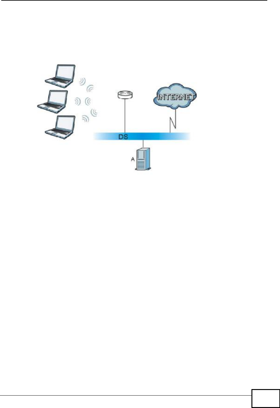
WPA(2)-PSK Application Example
A WPA(2)-PSK application looks as follows.
1First enter identical passwords into the AP and all wireless clients. The Pre-Shared
Key (PSK) must consist of between 8 and 63 ASCII characters or 64 hexadecimal
characters (including spaces and symbols).
2The AP checks each wireless client's password and allows it to join the network
only if the password matches.
3The AP and wireless clients generate a common PMK (Pairwise Master Key). The
key itself is not sent over the network, but is derived from the PSK and the SSID.
Appendix BWireless LANs
NWD2105 User’s Guide
144
4The AP and wireless clients use the TKIP or AES encryption process, the PMK and
information exchanged in a handshake to create temporal encryption keys. They
use these keys to encrypt data exchanged between them.
Figure 114 WPA(2)-PSK Authentication
Security Parameters Summary
Refer to this table to see what other security parameters you should configure for
each authentication method or key management protocol type. MAC address
filters are not dependent on how you configure these security features.
Table 31 Wireless Security Relational Matrix
AUTHENTICATION
METHOD/ KEY
MANAGEMENT
PROTOCOL
ENCRYPTIO
N METHOD ENTER
MANUAL KEY IEEE 802.1X
OpenNoneNoDisable
Enable without Dynamic WEP
Key
Open WEP No Enable with Dynamic WEP Key
Yes Enable without Dynamic WEP
Key
Yes Disable
Shared WEP No Enable with Dynamic WEP Key
Yes Enable without Dynamic WEP
Key
Yes Disable
WPA TKIP/AES No Enable
WPA-PSK TKIP/AES Yes Disable
WPA2 TKIP/AES No Enable
WPA2-PSK TKIP/AES Yes Disable

Appendix BWireless LANs
NWD2105 User’s Guide 145
Antenna Overview
An antenna couples RF signals onto air. A transmitter within a wireless device
sends an RF signal to the antenna, which propagates the signal through the air.
The antenna also operates in reverse by capturing RF signals from the air.
Positioning the antennas properly increases the range and coverage area of a
wireless LAN.
Antenna Characteristics
Frequency
An antenna in the frequency of 2.4GHz (IEEE 802.11b and IEEE 802.11g) or 5GHz
(IEEE 802.11a) is needed to communicate efficiently in a wireless LAN
Radiation Pattern
A radiation pattern is a diagram that allows you to visualize the shape of the
antenna’s coverage area.
Antenna Gain
Antenna gain, measured in dB (decibel), is the increase in coverage within the RF
beam width. Higher antenna gain improves the range of the signal for better
communications.
For an indoor site, each 1 dB increase in antenna gain results in a range increase
of approximately 2.5%. For an unobstructed outdoor site, each 1dB increase in
gain results in a range increase of approximately 5%. Actual results may vary
depending on the network environment.
Antenna gain is sometimes specified in dBi, which is how much the antenna
increases the signal power compared to using an isotropic antenna. An isotropic
antenna is a theoretical perfect antenna that sends out radio signals equally well
in all directions. dBi represents the true gain that the antenna provides.
Types of Antennas for WLAN
There are two types of antennas used for wireless LAN applications.

Appendix BWireless LANs
NWD2105 User’s Guide
146
•Omni-directional antennas send the RF signal out in all directions on a horizontal
plane. The coverage area is torus-shaped (like a donut) which makes these
antennas ideal for a room environment. With a wide coverage area, it is possible
to make circular overlapping coverage areas with multiple access points.
•Directional antennas concentrate the RF signal in a beam, like a flashlight does
with the light from its bulb. The angle of the beam determines the width of the
coverage pattern. Angles typically range from 20 degrees (very directional) to
120 degrees (less directional). Directional antennas are ideal for hallways and
outdoor point-to-point applications.
Positioning Antennas
In general, antennas should be mounted as high as practically possible and free of
obstructions. In point-to–point application, position both antennas at the same
height and in a direct line of sight to each other to attain the best performance.
For omni-directional antennas mounted on a table, desk, and so on, point the
antenna up. For omni-directional antennas mounted on a wall or ceiling, point the
antenna down. For a single AP application, place omni-directional antennas as
close to the center of the coverage area as possible.
For directional antennas, point the antenna in the direction of the desired
coverage area.

NWD2105 User’s Guide 147
APPENDIX C
Windows Wireless Management
This appendix shows you how to manage your NWD2105 using the Windows Vista
and Windows XP wireless configuration tools.
Windows Vista
Take the following steps to connect to a wireless network using the Windows Vista
wireless configuration tool (WLAN AutoConfig).
Appendix CWindows Wireless Management
NWD2105 User’s Guide
148
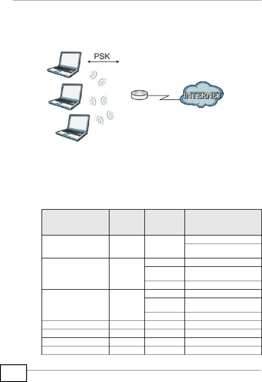
Connecting to a Wireless Network
1In the Windows Vista taskbar, click Start () > Connect To.
Figure 115 Vista: Start Menu
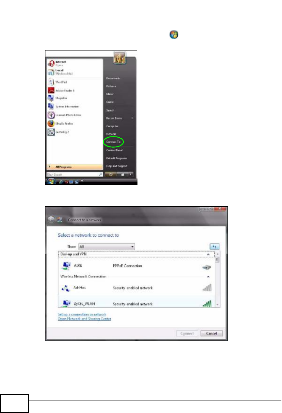
The Connect To window displays, showing all available networks.
Figure 116 Vista: The Connect To Window
The security status of each wireless network displays, as well as an indication of
its signal strength. If you use the mouse pointer to hover over a network’s entry,
additional information about the network displays.

Appendix CWindows Wireless Management
NWD2105 User’s Guide 149
Figure 117 Vista: Additional Information
2Double-click the network’s name to join the network, or select a network and click
Connect.
Note: If the network to which you want to connect does not display, see the section on
setting up a connection manually on page 151.
Appendix CWindows Wireless Management
NWD2105 User’s Guide
150
3If security is enabled, you may be prompted to enter your security key.
Figure 118 Vista: Enter Security Key
Your computer tries to connect to the wireless network.
Figure 119 Vista: Connecting
If your computer has connected to the wireless network successfully, the following
screen displays.
Appendix CWindows Wireless Management
NWD2105 User’s Guide 151
Figure 120 Vista: Successful Connection
4If you will use this network again, ensure that Save this network is selected. If
you save the network, you do not have to configure its settings again.
5Select Start this connection automatically if you want Windows to always try
to use this network when you start up your computer. If you do not select this (but
select Save this network) you can connect manually each time by clicking Start
>Connect to and selecting the network’s name from the list.
Connecting to a Network Manually
If the wireless network to which you want to connect does not appear in the
Connect to window (if your network’s SSID is hidden, for example), take the
following steps to configure your network connection manually
Appendix CWindows Wireless Management
NWD2105 User’s Guide
152
1Click Set up a connection or network at the bottom of the Connect to screen.
The following screen displays.
Figure 121 Vista: Choose a Connection Option
Appendix CWindows Wireless Management
NWD2105 User’s Guide 153
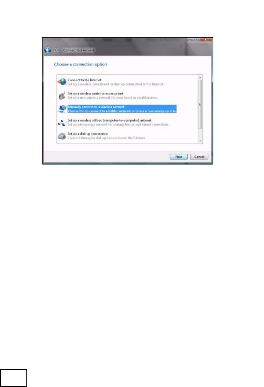
2Click Manually connect to a wireless network. The following screen displays.
Figure 122 Vista: Connect Manually
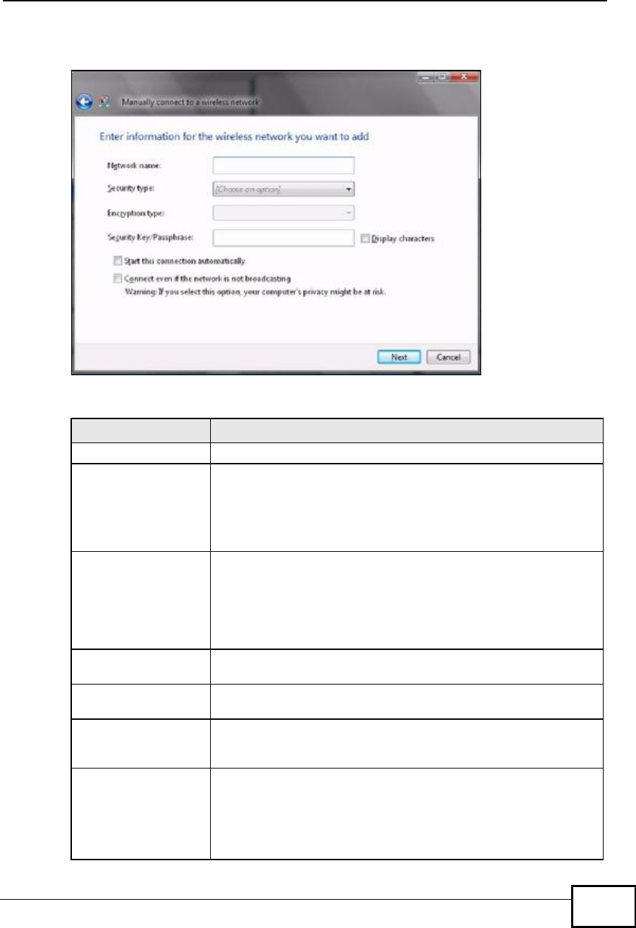
The following table describes the labels in this screen.
Table 32 Vista: Connect Manually
LABEL DESCRIPTION
Network nameEnter your network’s SSID (Service Set IDentifier).
Security typeSelect the type of security used by the network to which you
want to connect. The types of available security shown depend on
your computer’s wireless client.
In this field, WPA(2)-Personal is the same as WPA(2)-PSK,
and WPA(2)-Enterprise is the same as WPA(2)
Encryption typeSelect the type of encryption used by the network.
When you use WEP or 802.1x,WEP displays.
When you use a WPA mode (WPA(2)-Personal or WPA(2)-
Enterprise) you can choose AES or TKIP (if supported by your
computer’s wireless client).
Security Key /
Passphrase If your network uses WEP or WPA(2)-Personal security, enter
the key here.
Display CharactersSelect this if you do not want the security key characters to be
hidden.
Start this connection
automatically Select this box if you always want to try to connect to this
network at startup. If you leave this box unchecked, you will need
to connect manually each time.
Connect even if the
network is not
broadcasting
Select this box if you always want to try to connect to this
network at startup, even if the network is not broadcasting its
SSID. The warning in this field refers to the fact that if you do
this, your computer sends out probe request packets, which
contain the network’s SSID and could be used by an attacker to
access the network.
Appendix CWindows Wireless Management
NWD2105 User’s Guide
154
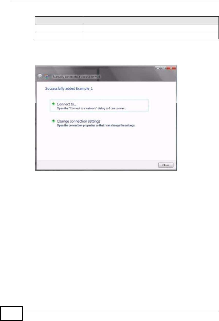
3When you have finished filling in the fields, click Next. the following screen
displays.
Figure 123 Vista: Successfully Added Network
4If you want to make any changes to the settings you just configured, click
Change connection settings. Otherwise, click Connect to.... In the window
that displays, double-click the new network’s name to connect to the network.
Setting Up An Ad-Hoc Network
Take the following steps to set up a wireless connection between two computers in
Windows Vista.
NextClick this to save your settings and move on to the next page.
CancelClick this to stop setting up your network.
Table 32 Vista: Connect Manually
LABEL DESCRIPTION
Appendix CWindows Wireless Management
NWD2105 User’s Guide 155
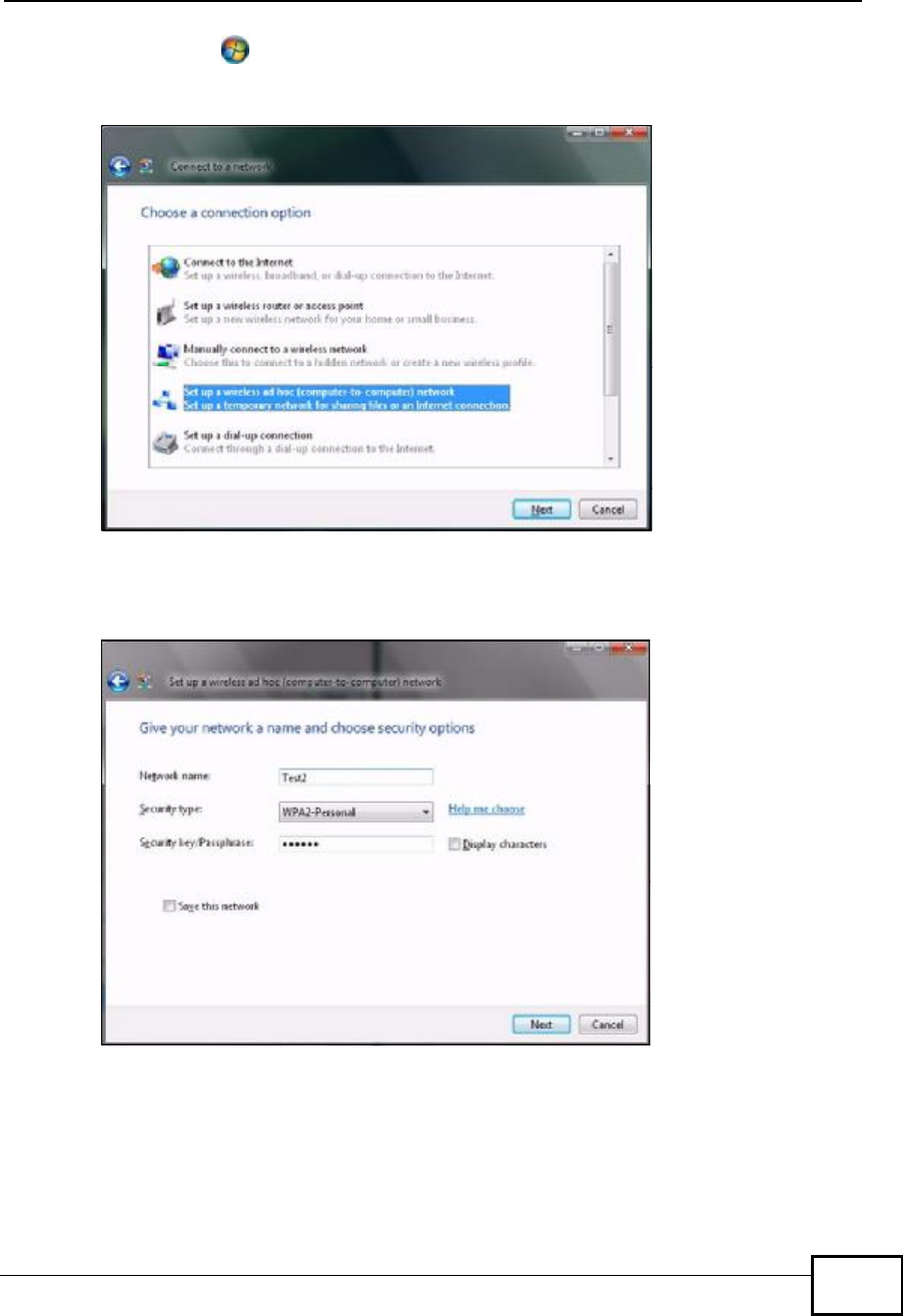
1Click Start () > Connect To. In the Connect to screen, click Set up a
connection or network. The following screen displays.
Figure 124 Vista: Set Up An Ad-hoc Network
2Select Set up a wireless ad hoc (computer-to-computer) network and click
Next. The following screen displays.
Figure 125 Vista: Ad-hoc Options
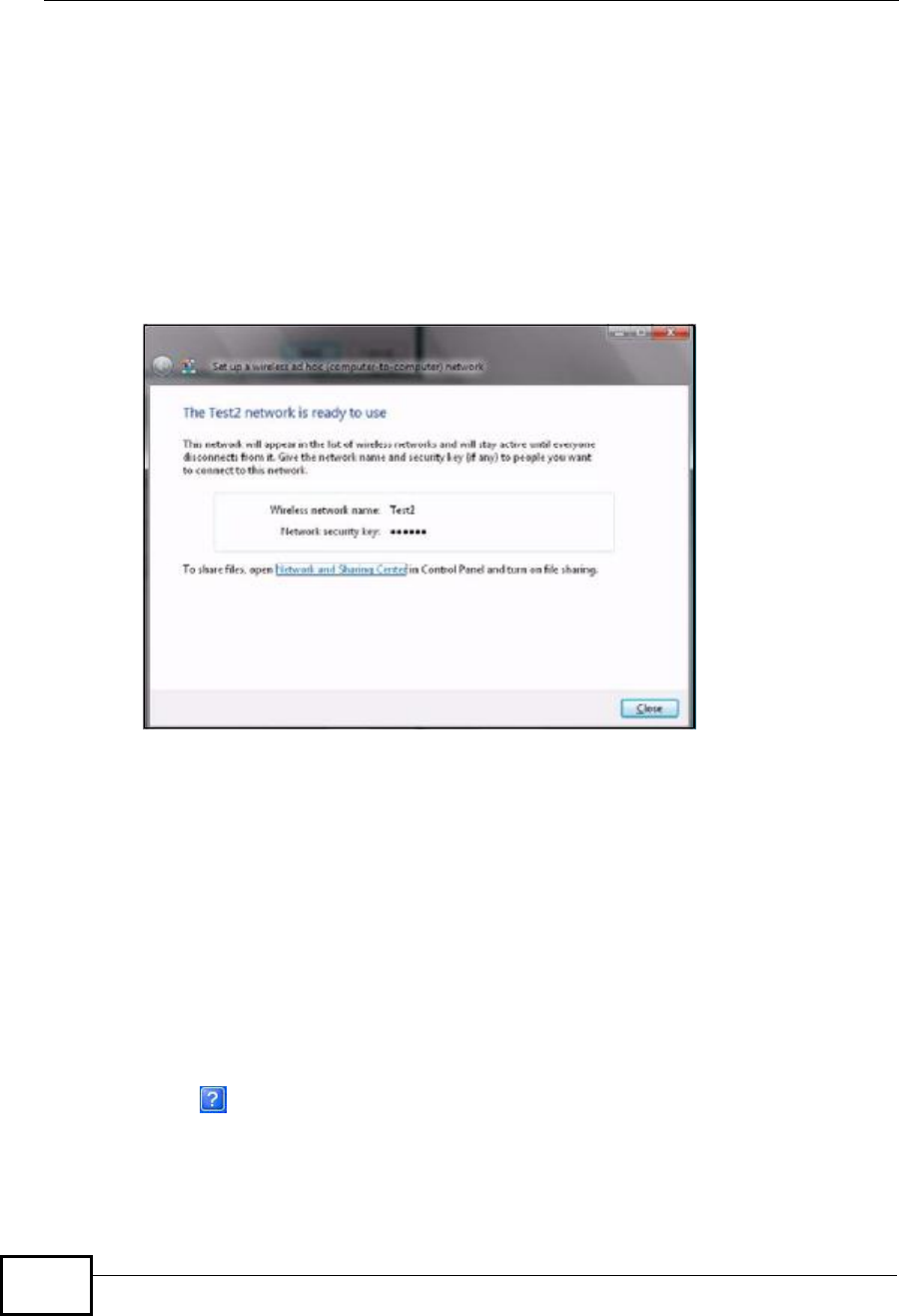
3Enter the Network name (SSID) you want to use for your network. Select a
Security type. If you are not sure what kind of security you want to use, click the
Help me choose link.
Note: Make sure all the wireless clients on your ad-hoc network can support the type
of security you select.
Appendix CWindows Wireless Management
NWD2105 User’s Guide
156
4Enter the Security key/Passphrase. Everybody on the network must enter this
key in their computer’s wireless client in order to access the network. If you want
to see the characters you entered, select the Display characters box. Otherwise,
leave it empty (dots display instead of the characters).
5If you will use this ad-hoc network again, select the Save this network box. If
you do this, the next time you click Start > Connect to, you can select the
network from the list.
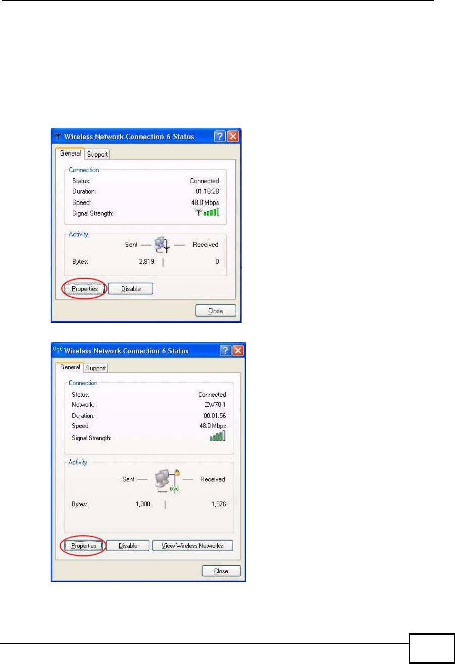
6Click Next. The following screen displays.
Figure 126 Vista: Ad-hoc Network Ready
7If you want to share files with other computers on the ad-hoc network, or let other
computers use your Internet connection, click the Network and Sharing Center
link. Otherwise, click Close.
Windows XP
Be sure you have the Windows XP service pack 2 installed on your computer.
Otherwise, you should at least have the Windows XP service pack 1 already on
your computer and download the support patch for WPA from the Microsoft web
site.
Windows XP SP2 screen shots are shown unless otherwise specified. Click the help
icon () in most screens, move the cursor to the item that you want the
information about and click to view the help.
Appendix CWindows Wireless Management
NWD2105 User’s Guide 157
Activating Wireless Zero Configuration
1Click Start,Control Panel and double-click Network Connections.
2Double-click on the icon for wireless network connection.
3The status window displays as shown below. Click Properties.
Figure 127 Windows XP SP1: Wireless Network Connection Status
Figure 128 Windows XP SP2: Wireless Network Connection Status
Appendix CWindows Wireless Management
NWD2105 User’s Guide
158
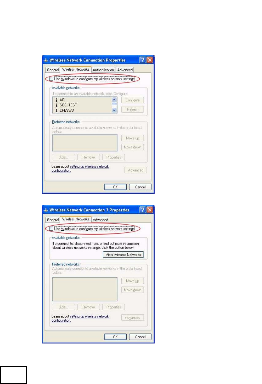
4The Wireless Network Connection Properties screen displays. Click the
Wireless Networks tab.
Make sure the Use Windows to configure my wireless network settings
check box is selected.
Figure 129 Windows XP SP1: Wireless Network Connection Properties
Figure 130 Windows XP SP2: Wireless Network Connection Properties
Appendix CWindows Wireless Management
NWD2105 User’s Guide 159
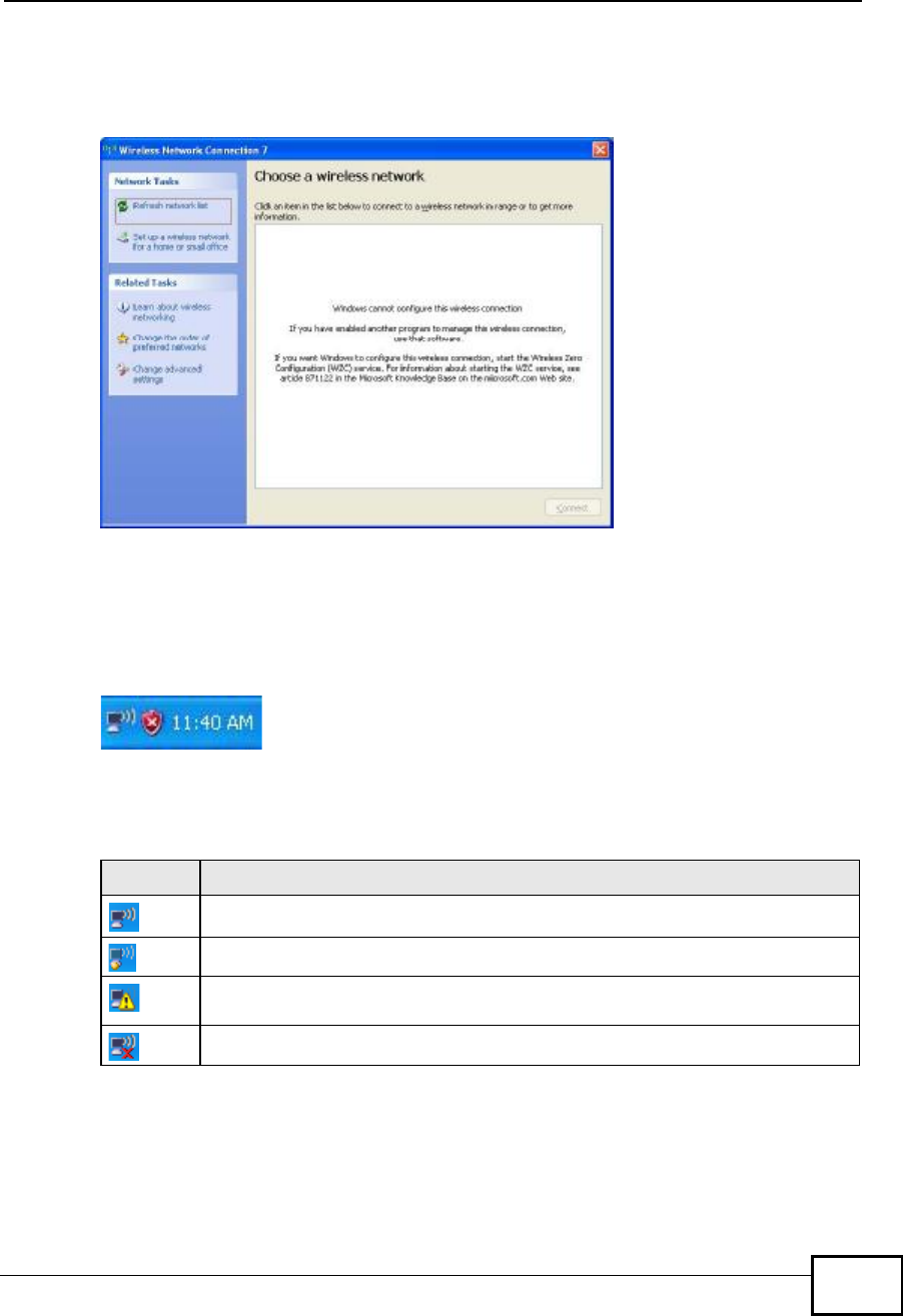
If you see the following screen, refer to article 871122 on the Microsoft web site
for information on starting WZC.
Figure 131 Windows XP SP2: WZC Not Available
Connecting to a Wireless Network
1Double-click the network icon for wireless connections in the system tray to open
the Wireless Network Connection Status screen.
Figure 132 Windows XP SP2: System Tray Icon
The type of the wireless network icon in Windows XP SP2 indicates the status of
the NWD2105. Refer to the following table for details.
Table 33 Windows XP SP2: System Tray Icon
ICON DESCRIPTION
The NWD2105 is connected to a wireless network.
The NWD2105 is in the process of connecting to a wireless network.
The connection to a wireless network is limited because the network did not
assign a network address to the computer.
The NWD2105 is not connected to a wireless network.
Appendix CWindows Wireless Management
NWD2105 User’s Guide
160
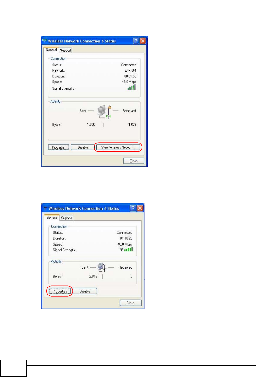
2Windows XP SP2: In the Wireless Network Connection Status screen, click
View Wireless Networks to open the Wireless Network Connection screen.
Figure 133 Windows XP SP2: Wireless Network Connection Status
Windows XP SP1: In the Wireless Network Connection Status screen, click
Properties and the Wireless Networks tab to open the Wireless Network
Connection Properties screen.
Figure 134 Windows XP SP1: Wireless Network Connection Status
Appendix CWindows Wireless Management
NWD2105 User’s Guide 161
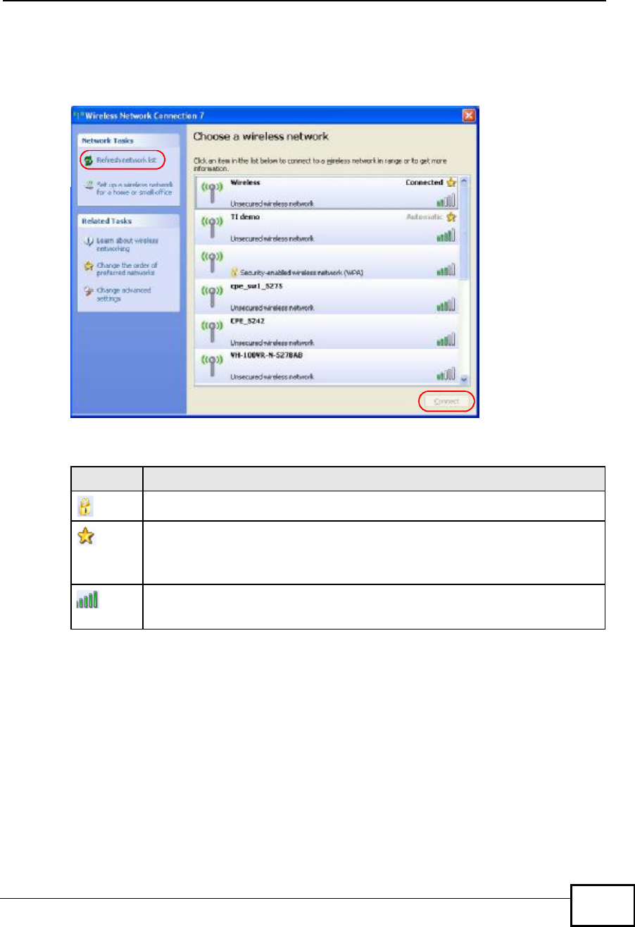
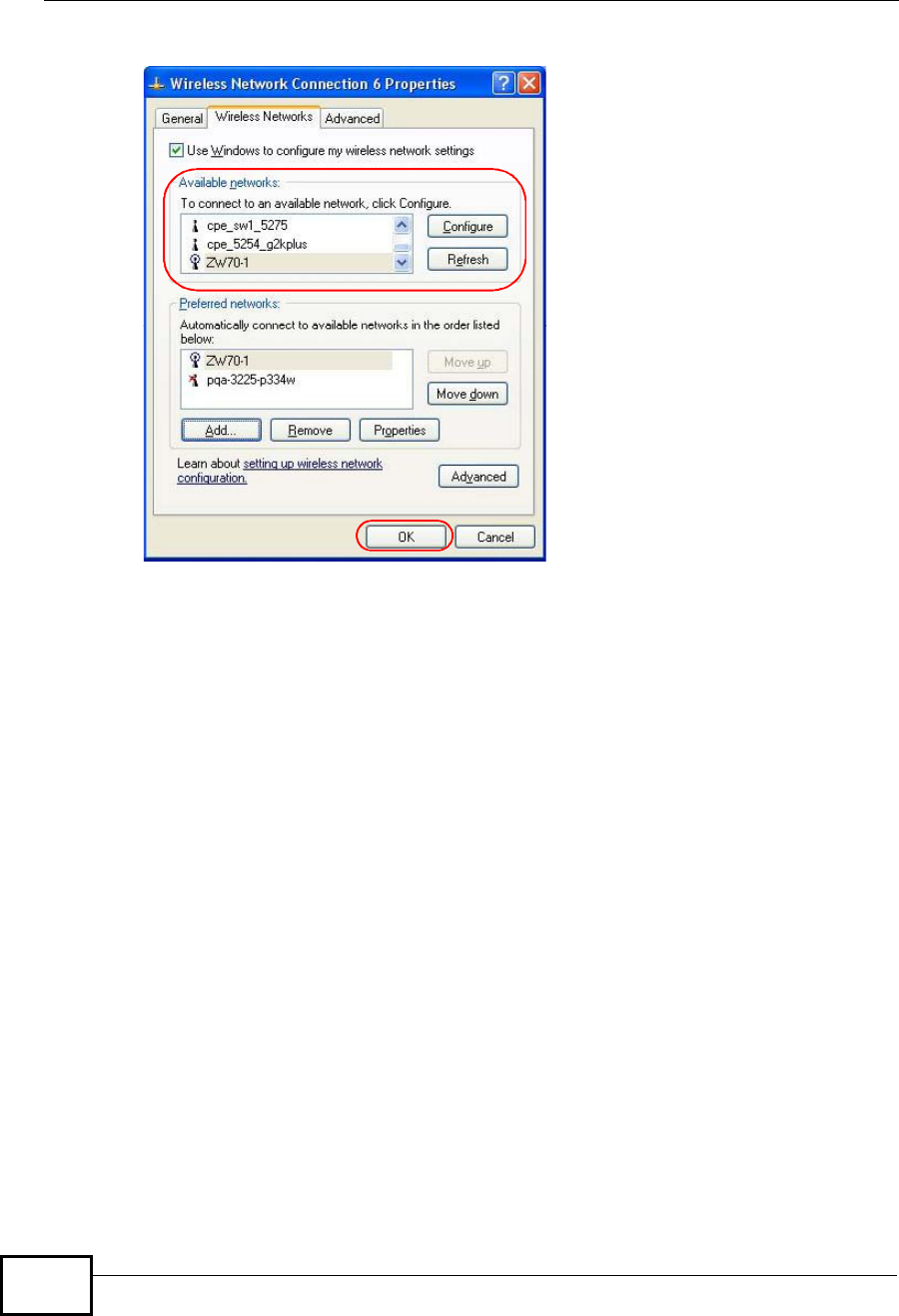
3Windows XP SP2: Click Refresh network list to reload and search for available
wireless devices within transmission range. Select a wireless network in the list
and click Connect to join the selected wireless network.
Figure 135 Windows XP SP2: Wireless Network Connection
The following table describes the icons in the wireless network list.
Windows XP SP1: Click Refresh to reload and search for available wireless
devices within transmission range. Select a wireless network in the Available
networks list, click Configure and set the related fields to the same security
settings as the associated AP to add the selected network into the Preferred
networks table. Click OK to join the selected wireless network. Refer to the section
on security settings (discussed later) for more information.
Table 34 Windows XP SP2: Wireless Network Connection
ICON DESCRIPTION
This denotes that wireless security is activated for the wireless network.
This denotes that this wireless network is your preferred network. Ordering
your preferred networks is important because the NWD2105 tries to associate
to the preferred network first in the order that you specify. Refer to the
section on ordering the preferred networks for detailed information.
This denotes the signal strength of the wireless network.
Move your cursor to the icon to see details on the signal strength.
Appendix CWindows Wireless Management
NWD2105 User’s Guide
162
Figure 136 Windows XP SP1: Wireless Network Connection Properties
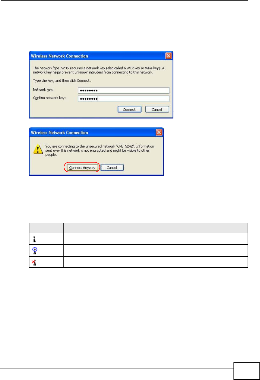
44.Windows XP SP2: If the wireless security is activated for the selected wireless
network, the Wireless Network Connection screen displays. You must set the
related fields in the Wireless Network Connection screen to the same security
settings as the associated AP and click Connect. Refer to the section about
Appendix CWindows Wireless Management
NWD2105 User’s Guide 163
security settings for more information. Otherwise click Cancel and connect to
another wireless network without data encryption. If there is no security activated
for the selected wireless network, a warning screen appears. Click Connect
Anyway if wireless security is not your concern.
Figure 137 Windows XP SP2: Wireless Network Connection: WEP or WPA-PSK
Figure 138 Windows XP SP2: Wireless Network Connection: No Security
5Verify that you have successfully connected to the selected network and check the
connection status in the wireless network list or the connection icon in the
Preferred networks or Available networks list.
The following table describes the connection icons.
Security Settings
When you configure the NWD2105 to connect to a secure network but the security
settings are not yet enabled on the NWD2105, you will see different screens
according to the authentication and encryption methods used by the selected
network.
Table 35 Windows XP: Wireless Networks
ICON DESCRIPTION
This denotes the wireless network is an available wireless network.
This denotes the NWD2105 is associated to the wireless network.
This denotes the wireless network is not available.
Appendix CWindows Wireless Management
NWD2105 User’s Guide
164
Association
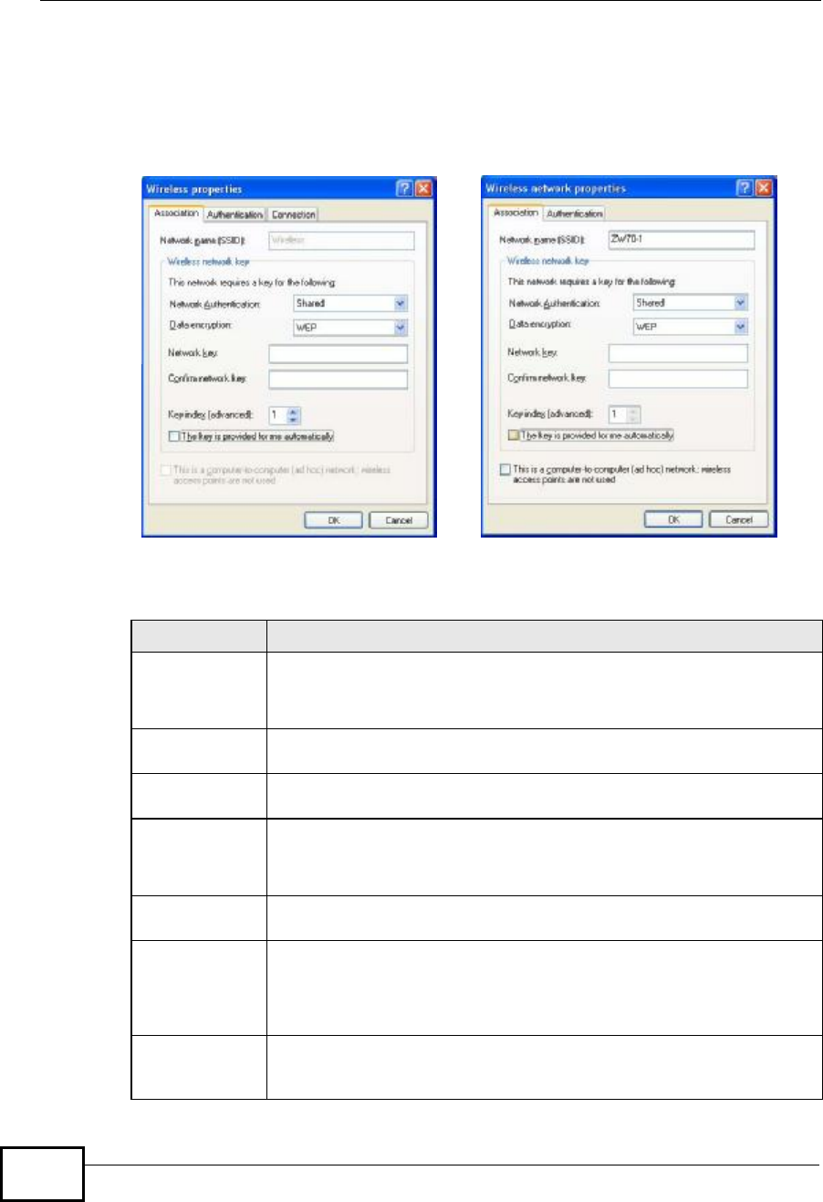
Select a network in the Preferred networks list and click Properties to view or
configure security.
Figure 139 Windows XP: Wireless (network) properties: Association
The following table describes the labels in this screen.
Table 36 Windows XP: Wireless (network) properties: Association
LABEL DESCRIPTION
Network name
(SSID) This field displays the SSID (Service Set IDentifier) of each wireless
network.
Network
Authentication This field automatically shows the authentication method (Share,
Open,WPA or WPA-PSK) used by the selected network.
Data EncryptionThis field automatically shows the encryption type (TKIP,WEP or
Disable) used by the selected network.
Network KeyEnter the pre-shared key or WEP key.
The values for the keys must be set up exactly the same on all wireless
devices in the same wireless LAN.
Confirm
network key Enter the key again for confirmation.
Key index
(advanced) Select a default WEP key to use for data encryption.
This field is available only when the network use WEP encryption
method and the The key is provided for me automatically check
box is not selected.
The key is
provided for me
automatically
If this check box is selected, the wireless AP assigns the NWD2105 a
key.
Appendix CWindows Wireless Management
NWD2105 User’s Guide 165
Authentication
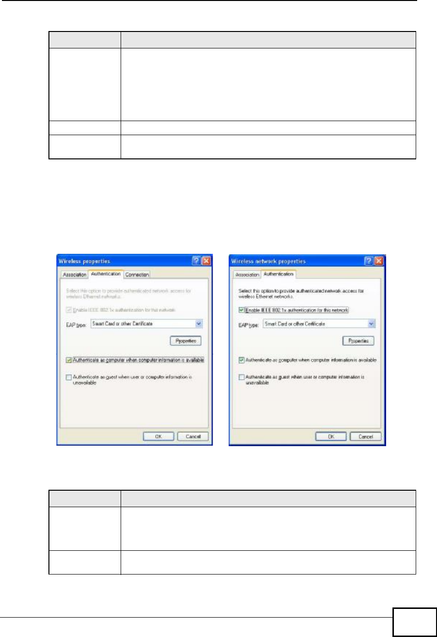
Click the Authentication tab in the Wireless (network) properties screen to
display the screen shown next. The fields on this screen are grayed out when the
network is in Ad-Hoc mode or data encryption is disabled.
Figure 140 Windows XP: Wireless (network) properties: Authentication
The following table describes the labels in this screen.
This is a
computer-to-
computer (ad
hoc) network;
wireless access
points are not
used
If this check box is selected, you are connecting to another computer
directly.
OKClick OK to save your changes.
CancelClick Cancel to leave this screen without saving any changes you may
have made.
Table 36 Windows XP: Wireless (network) properties: Association (continued)
LABEL DESCRIPTION
Table 37 Windows XP: Wireless (network) properties: Authentication
LABEL DESCRIPTION
Enable IEEE
802.1x
authentication
for this network
This field displays whether the IEEE 802.1x authentication is active.
If the network authentication is set to Open in the previous screen, you
can choose to disable or enable this feature.
EAP TypeSelect the type of EAP authentication. Options are Protected EAP
(PEAP) and Smart Card or other Certificate.
Appendix CWindows Wireless Management
NWD2105 User’s Guide
166
Authentication Properties
Select an EAP authentication type in the Wireless (network) properties:
Authentication screen and click the Properties button to display the following
screen.
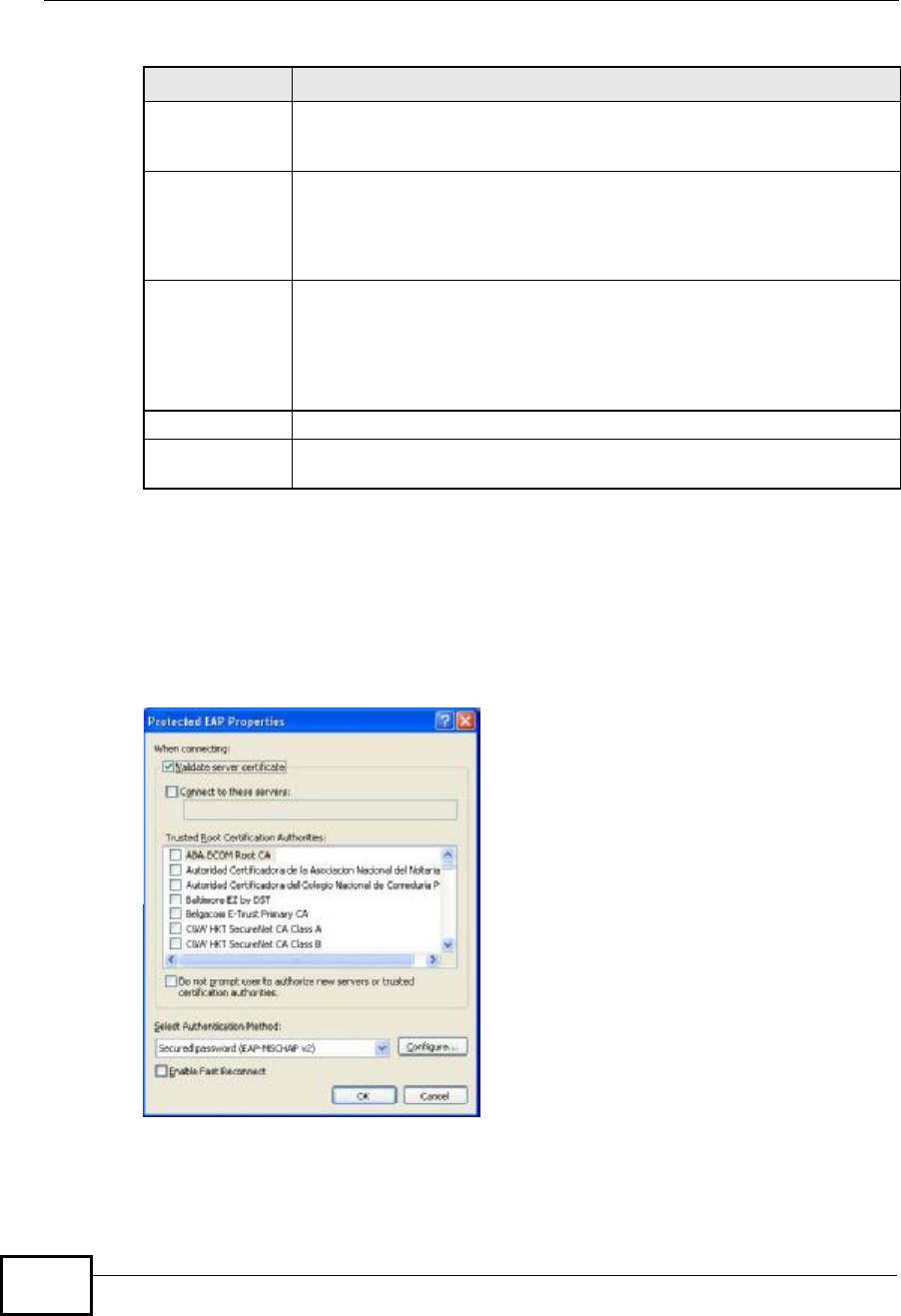
Protected EAP Properties
Figure 141 Windows XP: Protected EAP Properties
PropertiesClick this button to open the properties screen and configure
certificates. The screen varies depending on what you select in the EAP
type field.
Authenticate as
computer when
computer
information is
available
Select this check box to have the computer send its information to the
network for authentication when a user is not logged on.
Authenticate as
guest when
user or
computer
information is
unavailable
Select this check box to have the computer access to the network as a
guest when a user is not logged on or computer information is not
available.
OKClick OK to save your changes.
CancelClick Cancel to leave this screen without saving any changes you may
have made.
Table 37 Windows XP: Wireless (network) properties: Authentication (continued)
LABEL DESCRIPTION

Appendix CWindows Wireless Management
NWD2105 User’s Guide 167
The following table describes the labels in this screen.
Table 38 Windows XP: Protected EAP Properties
LABEL DESCRIPTION
Validate server
certificate Select the check box to verify the certificate of the authentication
server.
Connect to
these servers Select the check box and specify a domain in the field below to have
your computer connect to a server which resides only within this
domain.
Trusted Root
Certification
Authorities:
Select a trusted certification authority from the list below.
Note: You must first have a wired connection to a network and
obtain the certificate(s) from a certificate authority (CA).
Consult your network administrator for more information.
Do not prompt
user to
authorize new
server or
trusted
certification
authorities.
Select this check box to verify a new authentication server or trusted CA
without prompting.
This field is available only if you installed the Windows XP server pack 2.
Select
Authentication
Method:
Select an authentication method from the drop-down list box and click
Configure to do settings.
Enable Fast
Reconnect Select the check box to automatically reconnect to the network (without
re-authentication) if the wireless connection goes down.
OKClick OK to save your changes.
CancelClick Cancel to leave this screen without saving any changes you may
have made.
Appendix CWindows Wireless Management
NWD2105 User’s Guide
168
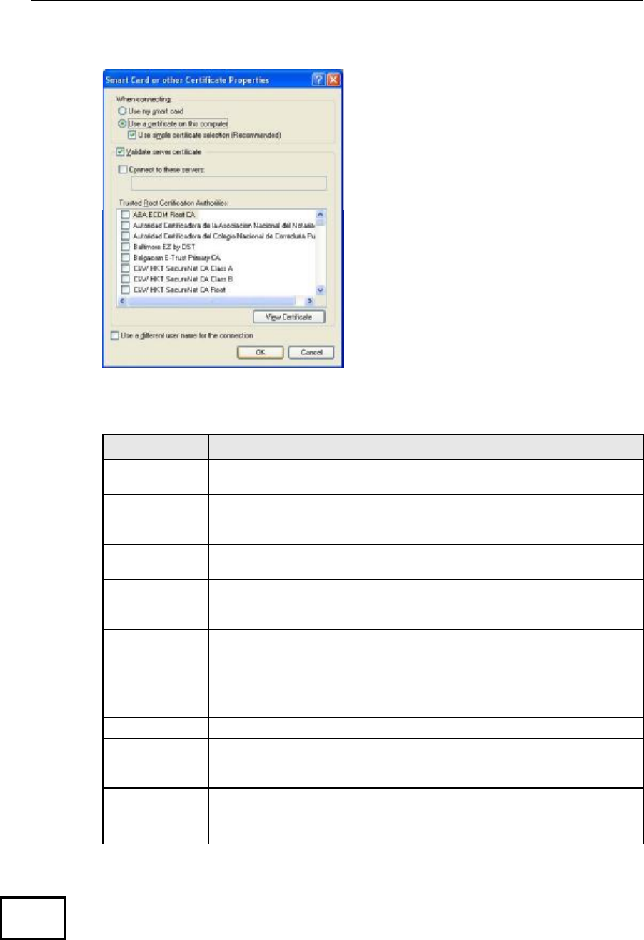
Smart Card or other Certificate Properties
Figure 142 Windows XP: Smart Card or other Certificate Properties
The following table describes the labels in this screen.
Table 39 Windows XP: Smart Card or other Certificate Properties
LABEL DESCRIPTION
Use my smart
card Select this check box to use the smart card for authentication.
Use a certificate
on this
computer
Select this check box to use a certificate on your computer for
authentication.
Validate server
certificate Select the check box to check the certificate of the authentication
server.
Connect to
these servers Select the check box and specify a domain in the field below to have
your computer connect to a server which resides only within this
domain.
Trusted Root
Certification
Authorities:
Select a trusted certification authority from the list below.
Note: You must first have a wired connection to a network and
obtain the certificate(s) from a certificate authority (CA).
Consult your network administrator for more information.
View CertificateClick this button if you want to verify the selected certificate.
Use a different
user name for
the connection:
Select the check box to use a different user name when the user name
in the smart card or certificate is not the same as the user name in the
domain that you are logged on to.
OKClick OK to save your changes.
CancelClick Cancel to leave this screen without saving any changes you may
have made.

Appendix CWindows Wireless Management
NWD2105 User’s Guide 169
Ordering the Preferred Networks
Follow the steps below to manage your preferred networks.
Appendix CWindows Wireless Management
NWD2105 User’s Guide
170
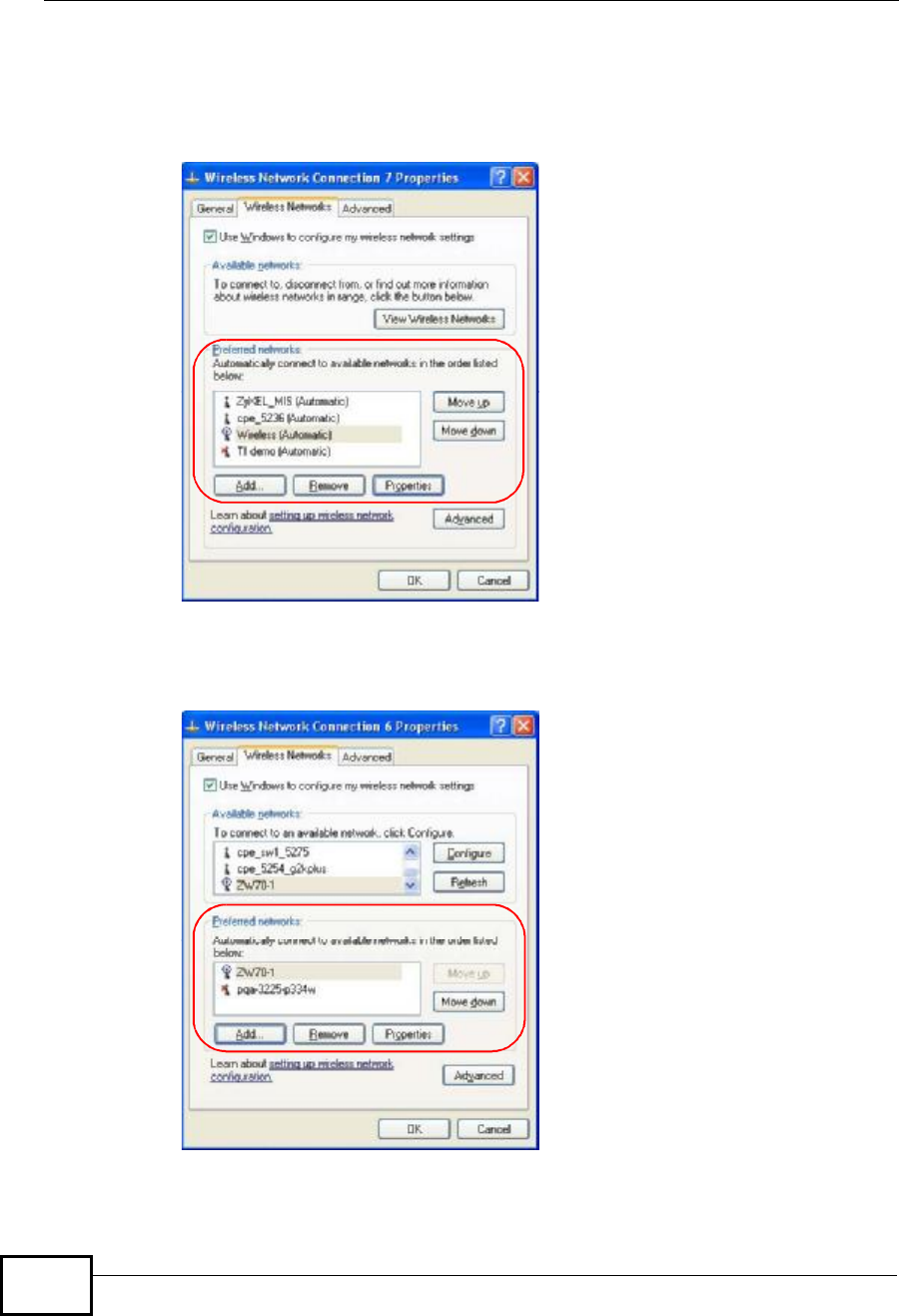
1Windows XP SP2: Click Change the order of preferred networks in the
Wireless Network Connection screen (see Figure 135 on page 161). The screen
displays as shown.
Figure 143 Windows XP SP2: Wireless Networks: Preferred Networks
Windows XP SP1: In the Wireless Network Connection Status screen, click
Properties and the Wireless Networks tab to open the screen as shown.
Figure 144 Windows XP SP1: Wireless Networks: Preferred Networks

Appendix CWindows Wireless Management
NWD2105 User’s Guide 171
2Whenever the NWD2105 tries to connect to a new network, the new network is
added in the Preferred networks table automatically. Select a network and click
Move up or Move down to change it's order, click Remove to delete it or click
Properties to view the security, authentication or connection information of the
selected network. Click Add to add a preferred network into the list manually.

Appendix CWindows Wireless Management
NWD2105 User’s Guide
172
NWD2105 User’s Guide 173
APPENDIX D
Wireless for Windows 7
Follow these steps to connect to a wireless network for a computer with the
Windows 7 Operating System (OS).
You should know the network name (SSID) of the wireless network to which you
want to connect. You should also know the password (pre-shared key (PSK)/
passphrase) if the wireless network is secured.
Enabling the Wireless Adapter
Do the following to enable the wireless adapter of your computer. If you know for
a fact that the wireless adapter is already working, you can skip this part and go
to Connecting to a Wireless Network.
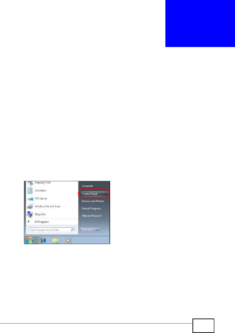
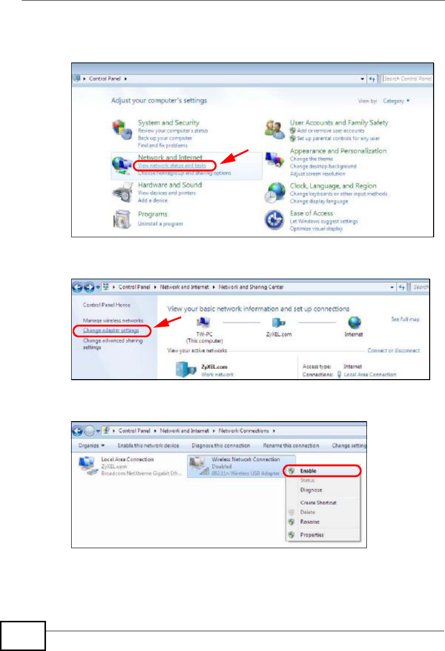
1Click Start > Control Panel.
Figure 145 Windows 7: Start Menu
Appendix DWireless for Windows 7
NWD2105 User’s Guide
174
2In the Control Panel, click View network status and tasks under the
Network and Internet category.
Figure 146 Windows 7: Control Panel
3Click Change adapter settings.
Figure 147 Windows 7: Network And Sharing Center
4Right click Wireless Network Connection and select Enable.
Figure 148 Windows 7: Wireless Network Connection
Appendix DWireless for Windows 7
NWD2105 User’s Guide 175
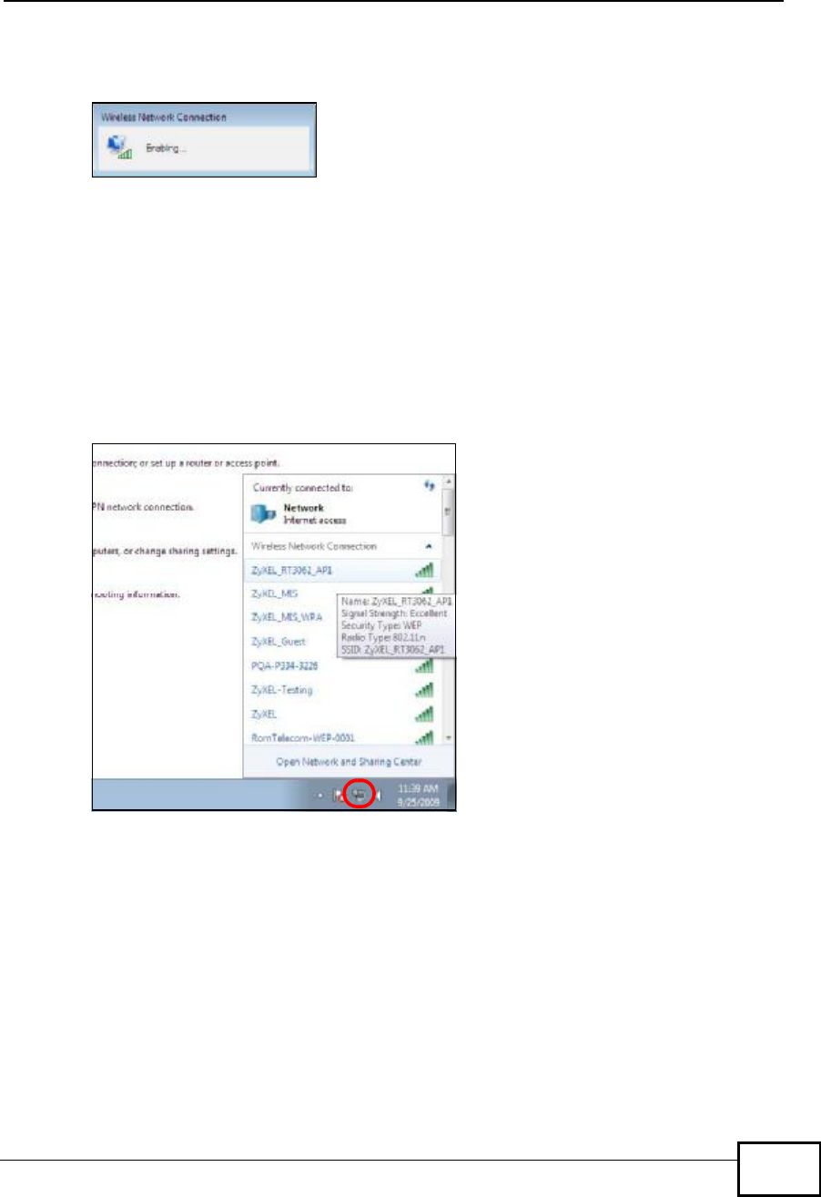
A progress indicator appears.
Figure 149 Windows 7: Enabling the Wireless Network Connection
When it shows Enabled, you are ready to connect to your wireless network.
Connecting to a Wireless Network
Once the computer’s wireless adapter has been enabled, do the following to
connect to a wireless network.
1Click the wireless adapter icon which appears in the bottom right of your computer
monitor. A list ofavailable wireless networks displays.
Figure 150 Windows 7: List of Wireless Networks
Appendix DWireless for Windows 7
NWD2105 User’s Guide
176
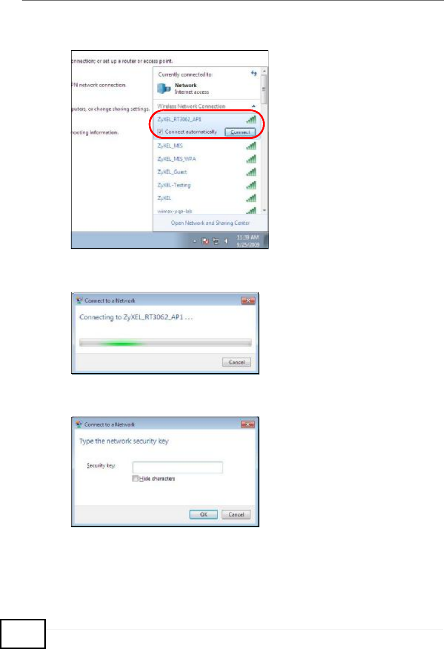
2Select a wireless network and click Connect.
Figure 151 Windows 7: Connect to the Wireless Networks
•If the wireless network is not password-protected, you should see a progress
indicator as follows.
Figure 152 Windows 7: Wireless Connection Progress Indicator
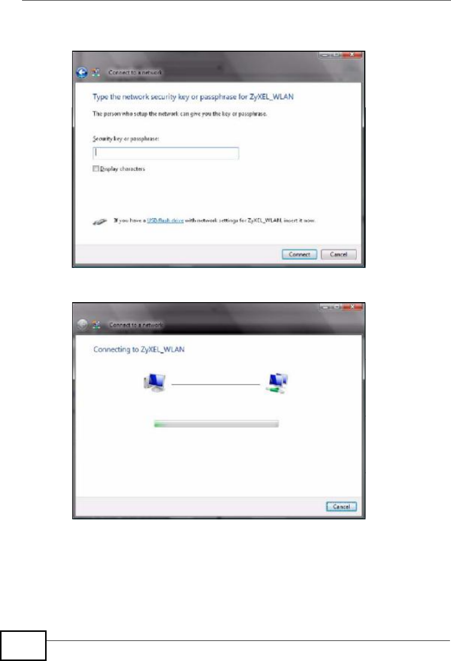
•If the wireless network is secured, you should provide the correct credentials
before you can gain access as shown below.
Figure 153 Windows 7: Wireless Connection Security
You may have to wait several minutes while your computer connects to the
wireless network.
Appendix DWireless for Windows 7
NWD2105 User’s Guide 177
Verifying the Settings
Open a web browser and try to access a website, such as www.zyxel.com.
Additionally, do the following to check your wireless network connection status.
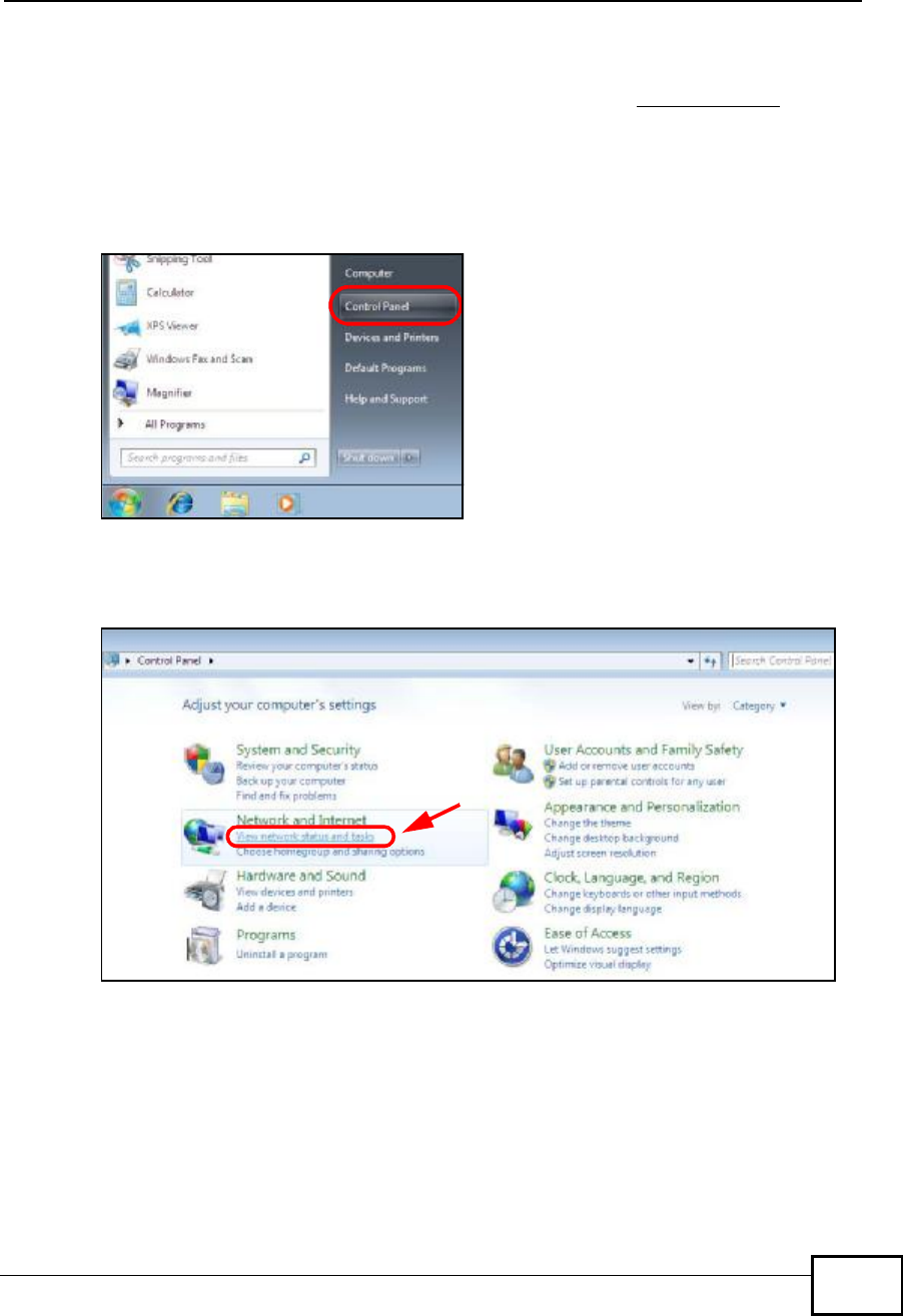
1Click Start > Control Panel.
Figure 154 Windows 7: Start Menu
2In the Control Panel, click View network status and tasks under the
Network and Internet category.
Figure 155 Windows 7: Control Panel
Appendix DWireless for Windows 7
NWD2105 User’s Guide
178
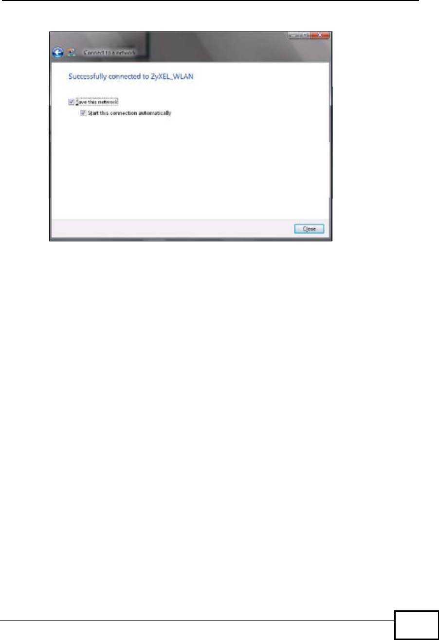
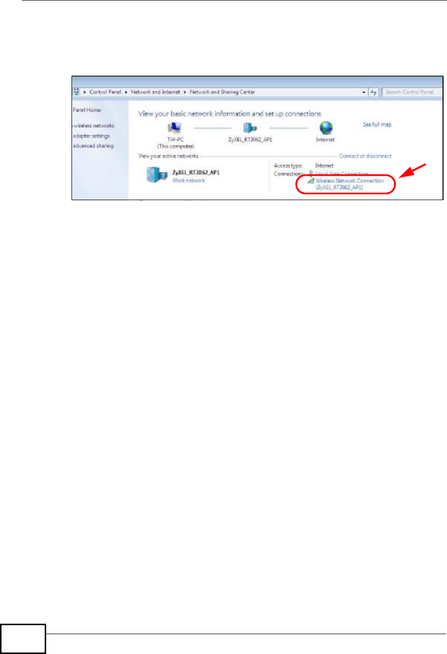
3Check the Connections under View you active networks. If the wireless
network name displays and the icon is green, you have successfully connected to
the wireless network.
Figure 156 Windows 7: Network and Sharing Center

NWD2105 User’s Guide 179
APPENDIX E
Legal Information
Copyright
Copyright © 2010 by ZyXEL Communications Corporation.
The contents of this publication may not be reproduced in any part or as a whole,
transcribed, stored in a retrieval system, translated into any language, or
transmitted in any form or by any means, electronic, mechanical, magnetic,
optical, chemical, photocopying, manual, or otherwise, without the prior written
permission of ZyXEL Communications Corporation.
Published by ZyXEL Communications Corporation. All rights reserved.
Disclaimers
ZyXEL does not assume any liability arising out of the application or use of any
products, or software described herein. Neither does it convey any license under
its patent rights nor the patent rights of others. ZyXEL further reserves the right
to make changes in any products described herein without notice. This publication
is subject to change without notice.
Trademarks
Trademarks mentioned in this publication are used for identification purposes only
and may be properties of their respective owners.
Certifications
Federal Communications Commission (FCC) Interference Statement
The device complies with Part 15 of FCC rules. Operation is subject to the
following two conditions:
•This device may not cause harmful interference.
•This device must accept any interference received, including interference that
may cause undesired operations.
Appendix ELegal Information
NWD2105 User’s Guide
180
This device has been tested and found to comply with the limits for a Class B
digital device pursuant to Part 15 of the FCC Rules. These limits are designed to
provide reasonable protection against harmful interference in a residential
installation. This device generates, uses, and can radiate radio frequency energy,
and if not installed and used in accordance with the instructions, may cause
harmful interference to radio communications. However, there is no guarantee
that interference will not occur in a particular installation.
If this device does cause harmful interference to radio/television reception, which
can be determined by turning the device off and on, the user is encouraged to try
to correct the interference by one or more of the following measures:
1Reorient or relocate the receiving antenna.
2Increase the separation between the equipment and the receiver.
3Connect the equipment into an outlet on a circuit different from that to which the
receiver is connected.
4Consult the dealer or an experienced radio/TV technician for help.
FCC Radiation Exposure Statement
•This device has been tested to the FCC exposure requirements (Specific
Absorption Rate).
•This device complies with the requirements of Health Canada Safety Code 6 for
Canada.
•Testing was performed on laptop computers with antennas at 5mm spacing. The
maximumSARvalueis:0.733W/kg. The device mustnotbe collocatedwith any
other antennas or transmitters.
•This equipment has been SAR-evaluated for use in laptops (notebooks) with side
slot configuration.
•The device complies with FCC RF radiation exposure limits set forth for an
uncontrolled environment, under 47 CFR 2.1093 paragraph (d)(2). End users
must follow the specific operating instructions for satisfying RF exposure
compliance.To maintain compliance with FCC RF exposure compliance
requirements, please follow operation instruction as documented in this manual.
•This transmitter must not be co-located or operating in conjunction with any
other antenna or transmitter.
•IEEE 802.11b or 802.11g operation of this product in the U.S.A. is firmware-
limited to channels 1 through 11.

Appendix ELegal Information
NWD2105 User’s Guide 181
Industry Canada Statement
This device complies with RSS-210 of the Industry Canada Rules. Operation is
subject to the following two conditions:
1) this device may not cause interference and
2) this device must accept any interference, including interference that may cause
undesired operation of the device
This device has been designed to operate with an antenna having a maximum
gainof3.1 dBi.
Antenna having a higher gain is strictly prohibited per regulations of Industry
Canada. The required antenna impedance is 50 ohms.
To reduce potential radio interference to other users, the antenna type and its gain
should be so chosen that the EIRP is not more than required for successful
communication.
IC Radiation Exposure Statement
This equipment complies with IC radiation exposure limits set forth for an
uncontrolled environment. End users must follow the specific operating
instructions for satisfying RF exposure compliance.
Notices
Changes or modifications not expressly approved by the party responsible for
compliance could void the user's authority to operate the equipment.
This device has been designed for the WLAN 2.4 GHz network throughout the EC
region and Switzerland, with restrictions in France.

Appendix ELegal Information
NWD2105 User’s Guide
182
This Class B digital apparatus complies with Canadian ICES-003. Operation is
subject to the following two conditions: (1) this device may not cause
interference, and (2) this device must accept any interference, including
interference that may cause undesired operation of the device.
Cet appareil numérique de la classe B est conforme à la norme NMB-003 du
Canada.
Viewing Certifications
1Go to http://www.zyxel.com.
2Select your product on the ZyXEL home page to go to that product's page.
3Select the certification you wish to view from this page.
ZyXEL Limited Warranty
ZyXEL warrants to the original end user (purchaser) that this product is free from
any defects in material or workmanship for a specific period (the Warranty Period)
from the date of purchase. The Warranty Period varies by region. Check with your
vendor and/or the authorized ZyXEL local distributor for details about the
Warranty Period of this product. During the warranty period, and upon proof of
purchase, should the product have indications of failure due to faulty workmanship
and/or materials, ZyXEL will, at its discretion, repair or replace the defective
products or components without charge for either parts or labor, and to whatever
extent it shall deem necessary to restore the product or components to proper
operating condition. Any replacement will consist of a new or re-manufactured
functionally equivalent product of equal or higher value, and will be solely at the
discretion of ZyXEL. This warranty shall not apply if the product has been
modified, misused, tampered with, damaged by an act of God, or subjected to
abnormal working conditions.
Note
Repair or replacement, as provided under this warranty, is the exclusive remedy of
the purchaser. This warranty is in lieu of all other warranties, express or implied,
including any implied warranty of merchantability or fitness for a particular use or
purpose. ZyXEL shall in no event be held liable for indirect or consequential
damages of any kind to the purchaser.
To obtain the services of this warranty, contact your vendor. You may also refer to
the warranty policy for the region in which you bought the device at http://
www.zyxel.com/web/support_warranty_info.php.


Appendix ELegal Information
NWD2105 User’s Guide
184

Index
NWD2105 User’s Guide 185
Index
A
About 86
about your ZyXEL Device 18
Access Point (AP) 38
Access point (AP) 38
Access Point. See also AP.
ACT LED 19
activating a profile 67
adapter 68
Ad-Hoc 20,65
Advanced Encryption Standard 41
See AES.
advanced settings 68
AES 141
antenna
directional 146
gain 145
omni-directional 146
Antenna gain 80
Antenna output power 78
APSee also access point.
AP (access point) 133
AP MAC address 52
AP mode
configuration 34
Association list 35,78
authentication 52
authentication type 40
auto 40
open system 40
shared key 40
auto authentication 40
automatic connection 54
automatic network scan 29,62
B
Basic Service Set, See BSS 131
BSS 131
C
CA 41,139
CCMP 41
Certificate Authority
See CA.
certifications 179
notices 181
viewing 182
channel 39,52,54,55,65,79,133
interference 133
configuration method 21
important note 21
Wireless Zero Configuration (WZC) 20,21
ZyXEL utility 21
configuration status 51,78
connection status 51,78
copyright 179
creating a new profile 64
credentials 72
CTS (Clear to Send) 134
current configuration 51,78
current connection status 51,78
D
data encryption 55
digital ID 41
dimensions 95
disclaimer 179
download 87
driver version 86

Index
NWD2105 User’s Guide
186
dynamic WEP key exchange 140
E
EAP (Extensible Authentication Protocol) 40
EAP Authentication 138
EAP authentication 41
EAP type 71
EAP-PEAP 40
EAP-TLS 40
EAP-TTLS 40
encryption 141
encryption type 40,59
environmental specifications 95
ESS 132
Extended Service Set, See ESS 132
F
FCC interference statement 179
fragmentation threshold 135
frequency 39,96
G
getting started 17
H
hardware connections 20
help 22
hidden node 133
humidity 95
I
IBSS 131
IEEE 802.11g 135
IEEE 802.1x 40,59,71
Independent Basic Service Set
See IBSS 131
infrastructure 19
initialization vector (IV) 141
installation 20
interface 95
Internet access 19
IP address
dynamic 77
L
LEDs 19
lights 19
link information 51,78
LINK LED 19
link quality 52
M
MAC 78
MAC filter 83
action 84
manual network connection 29
Mbps 78
Message Integrity Check (MIC) 41,141
N
Network interface card (NIC) 80
network mode 52
network name 52
network overlap 39
network scan 62
Network sharing 77
network type 52,55

Index
NWD2105 User’s Guide 187
O
online help 22
Output power 78
P
packet collisions 52
Pairwise Master Key (PMK) 141,143
passphrase 40,56,81
password 40
PEAP 71,72
peer computer 19,65
physical specifications 95
power saving mode 68
preamble mode 135
product registration 183
product specifications 95
Profile 62
profile 51,63
activation 67
add new 64
configure 29,31
default 62
delete 63
edit 63
information 63
new 63,64
PSK 141
Q
Quick Start Guide 20,92
R
radio interference 92
radio specifications 95,96
RADIUS 40,41,137
message types 137
messages 137
shared secret key 138
real-time data traffic statistics 53
receive rate 52
receive speed 52
registration
product 183
related documentation 3
RTS (Request To Send) 134
threshold 133,134
S
safety warnings 7
Save power 80
save power 68
scan 54
scan info 65
search 54
Security 78
security 39,52,97
data encryption 39
security settings and Vista 71
sensitivity 96
Service Set Identity (SSID) 29,38
signal strength 52,54
site information 54
site survey 54
scan 54
security settings 55,80
sleep mode 68
SSID 29,38,52,54,78,93
statistics 52
syntax conventions 5
system tray 20
T
temperature 95
Temporal Key Integrity Protocol (TKIP) 41,141
The 71
TLS 71,73
total receive 52

Index
NWD2105 User’s Guide
188
total transmit 52
trademarks 179
Transmission rate 78
transmission rate 52,64
transmit key 56,81
transmit rate 52
trend chart 52,53
TTLS 71
U
uninstalling the ZyXEL utility 86
upgrading the ZyXEL utility 87
important step 87
user authentication 39
utility installation 20
utility version 86
V
Vista 71,73
W
warranty 182
note 182
weight 95
WEP 39,56
automatic setup 40
manual setup 40,57,82
passphrase 40,56,81
WEP (Wired Equivalent Privacy) 39
WEP Encryption 56
WEP key generation 40
Wi-Fi Protected Access 41,140
Wi-Fi Protected Setup 51
Windows 71
Windows XP 21
Wired network 80
wireless client 38
wireless client WPA supplicants 142
wireless LAN
introduction 37
security 39
wireless LAN (WLAN) 37
wireless network 38
wireless security 136
wireless standard 95
Wireless station mode
profile 62
wireless station mode
adapter 68
security settings 55,80
site survey 54
trend chart 53
wireless tutorial 24
WLAN
interference 133
security parameters 144
WPA 41,58,71,140
key caching 142
pre-authentication 142
user authentication 142
vs WPA-PSK 141
wireless client supplicant 142
with RADIUS application example 142
WPA2 41,58,71,140
user authentication 142
vs WPA2-PSK 141
wireless client supplicant 142
with RADIUS application example 142
WPA2-Pre-Shared Key 41,140
WPA2-PSK 41,57,82,140,141
application example 143
WPA-PSK 41,57,82,141
application example 143
WPS
see also Wi-Fi Protected Setup 51
WZC
activating 157
network connection 159
not available 159
preferred network 169
security setting 163
system tray icon 159
WZC (Wireless Zero Configuration) 21

Index
NWD2105 User’s Guide 189
Z
ZyXEL Utility
accessing 21
ZyXEL utility 21
accessing 21
driver version number 86
exiting 21
help 22
reactivating 21
status 21
system tray icon 20
upgrading 87
version number 86