ZyXEL Communications P3202HNBA 802.11N GPON VoIP IAD User Manual ZyBook2
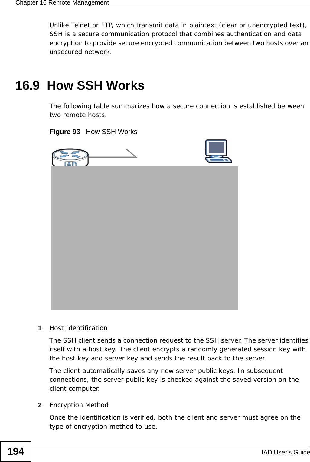
ZyXEL Communications Corporation 802.11N GPON VoIP IAD ZyBook2
UserManual.wiki
>
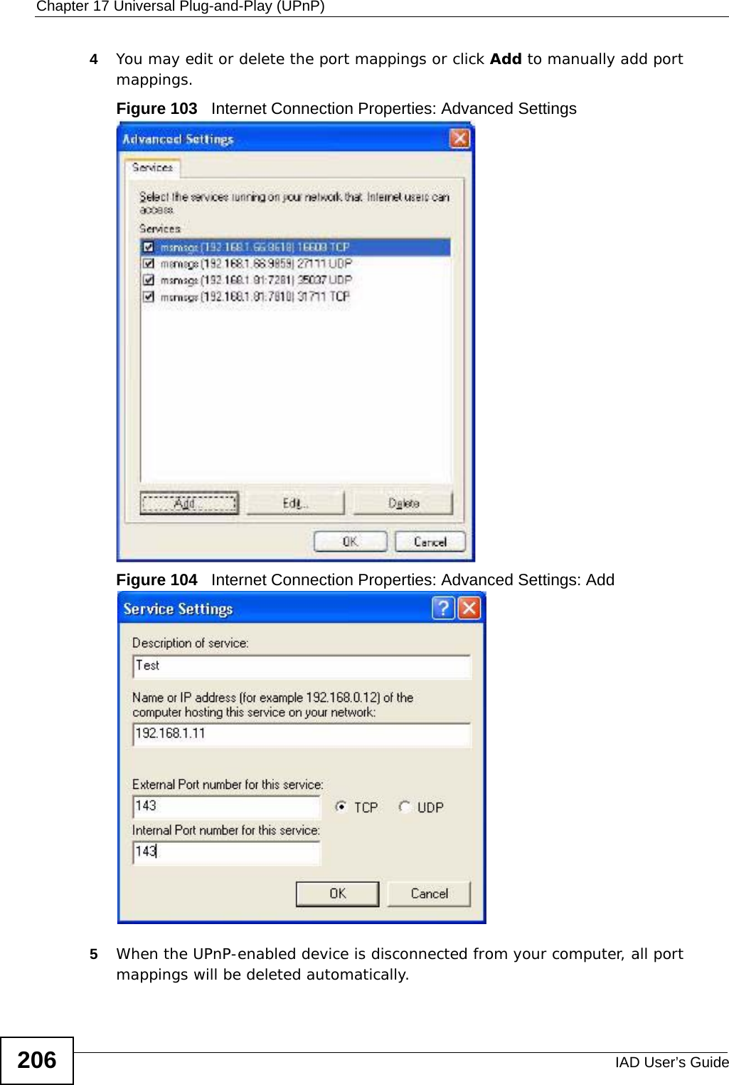
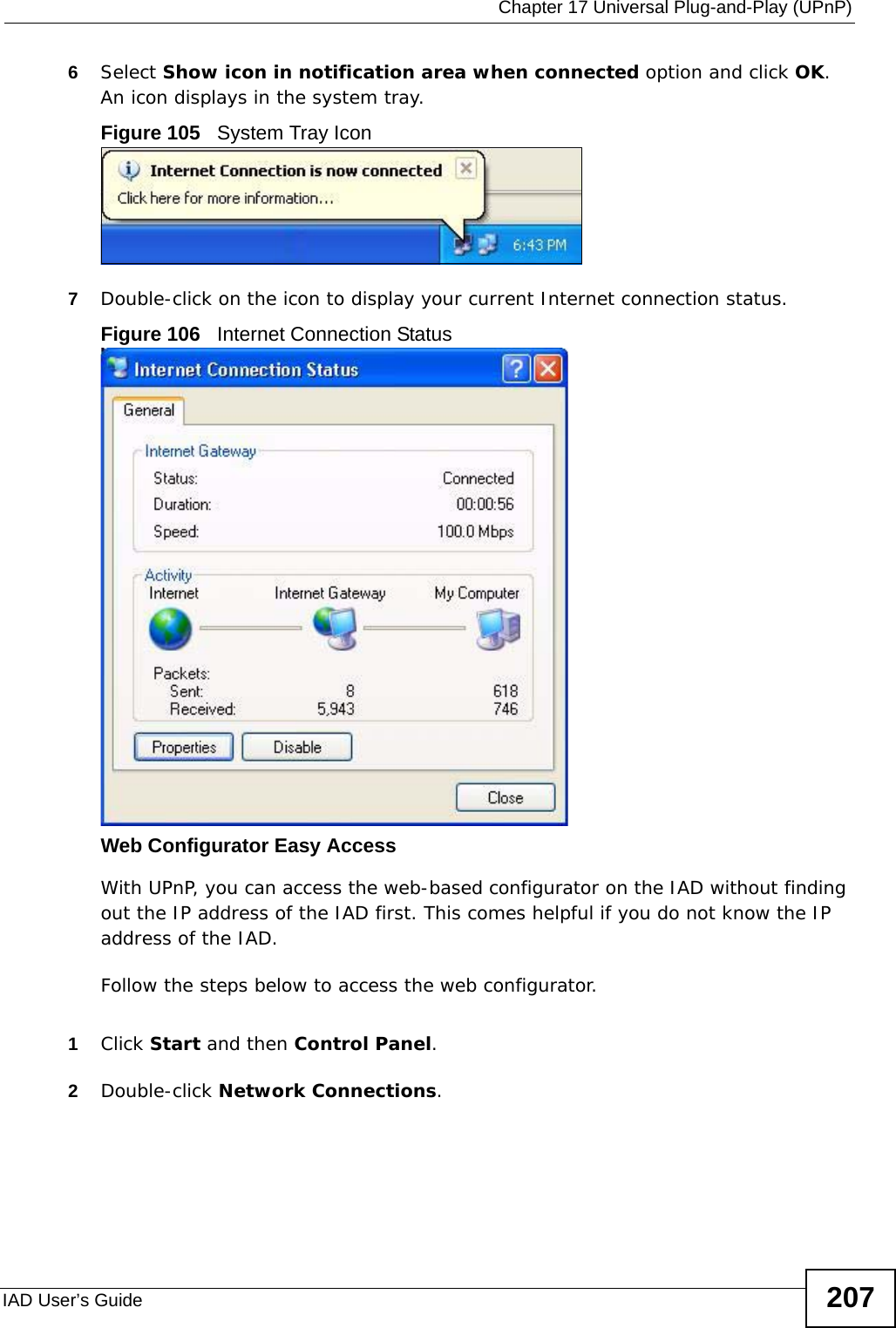
ZyXEL Communications
>
P3202HNBA User Manual
>
Installation guide 1 of 2
Contents
1.
Installation guide 1 of 2
2.
Installation guide 2 of 2
Installation guide 1 of 2
Navigation menu
Upload a User Manual
Namespaces
Wiki Guide
HTML
PDF
Info
Views
User Manual
Discussion / Help
Navigation
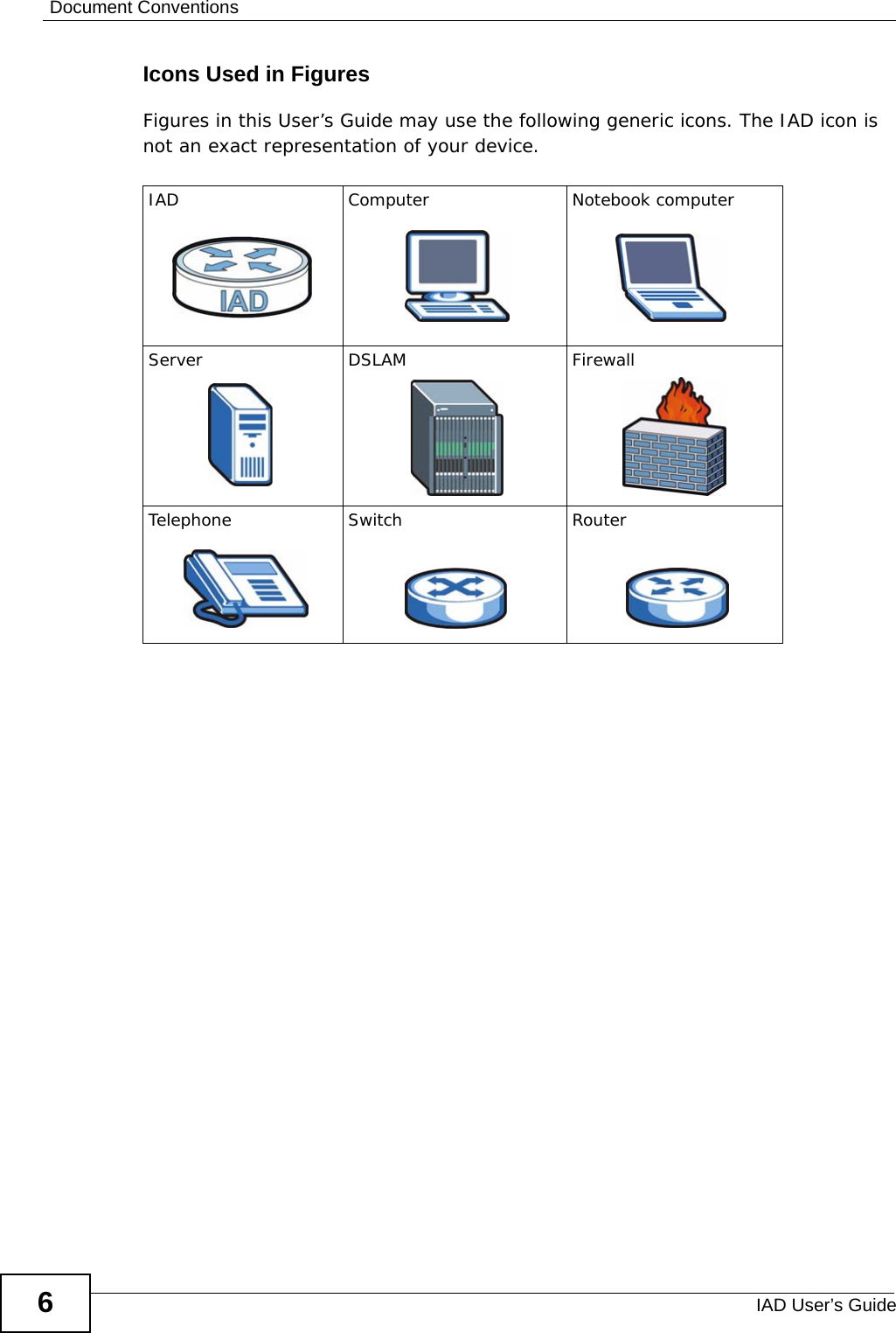
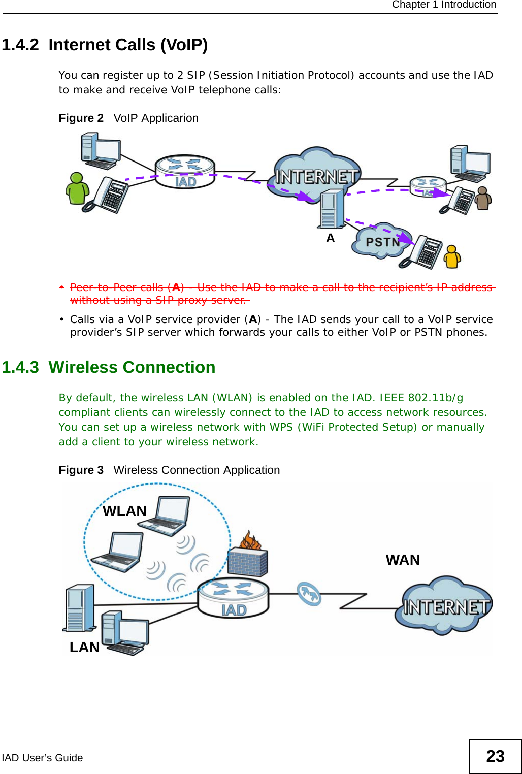
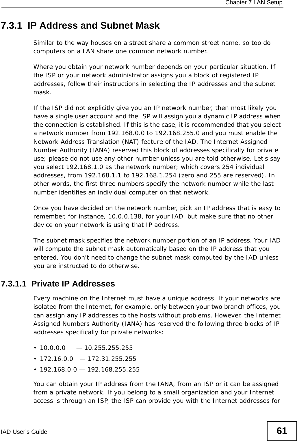
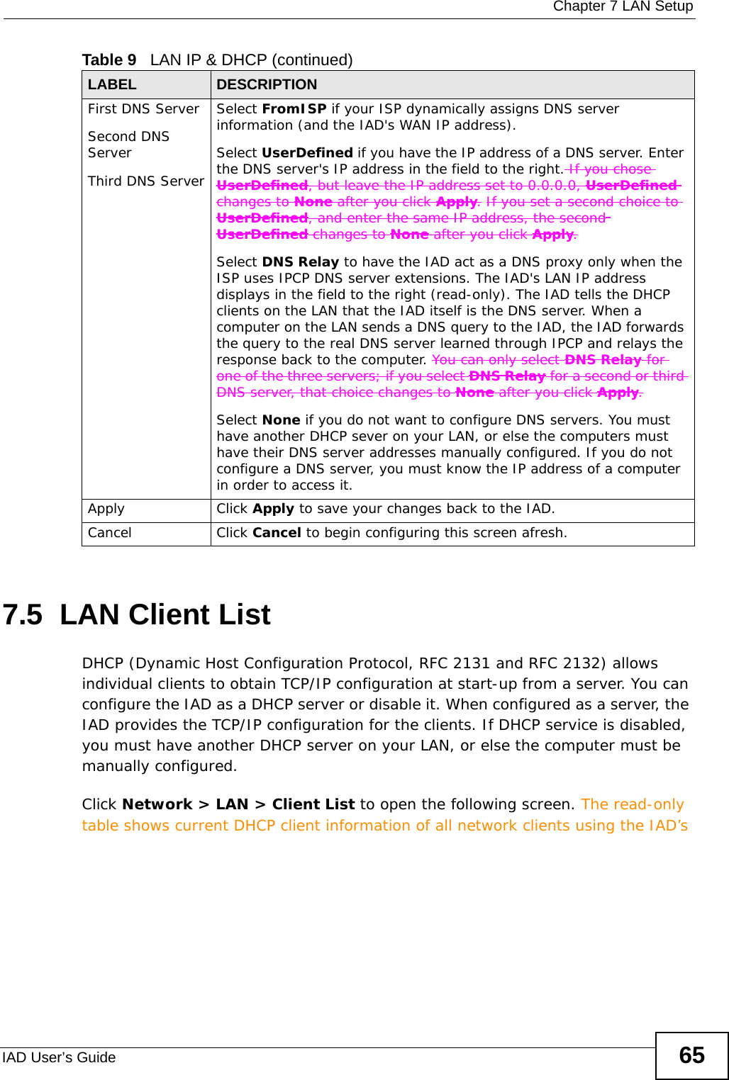
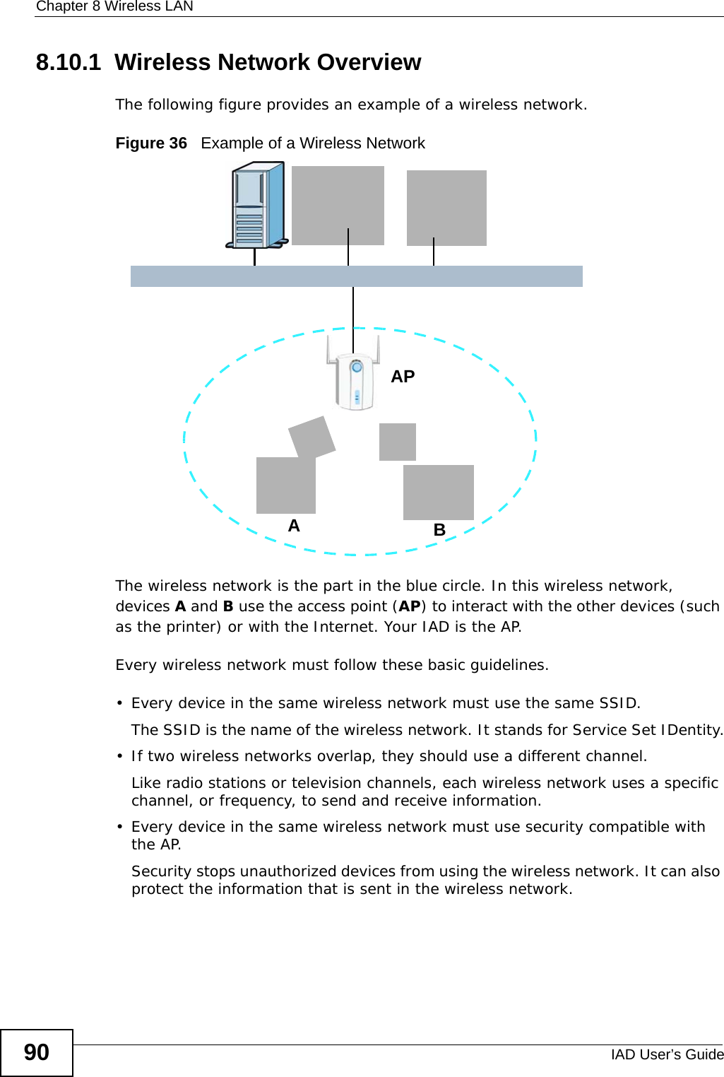
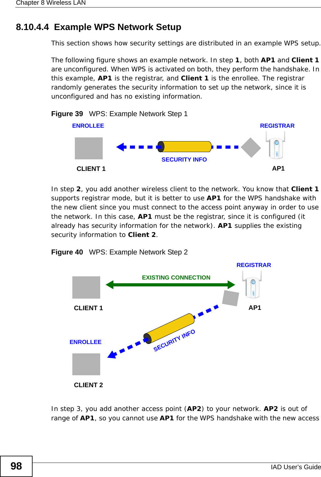
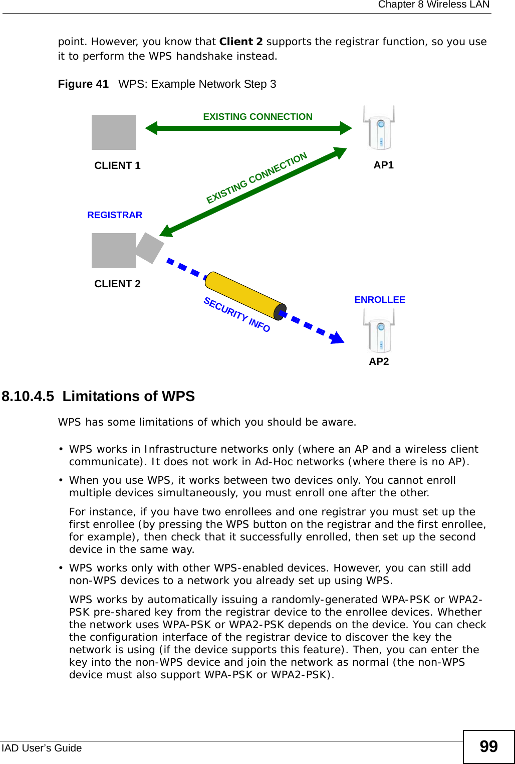
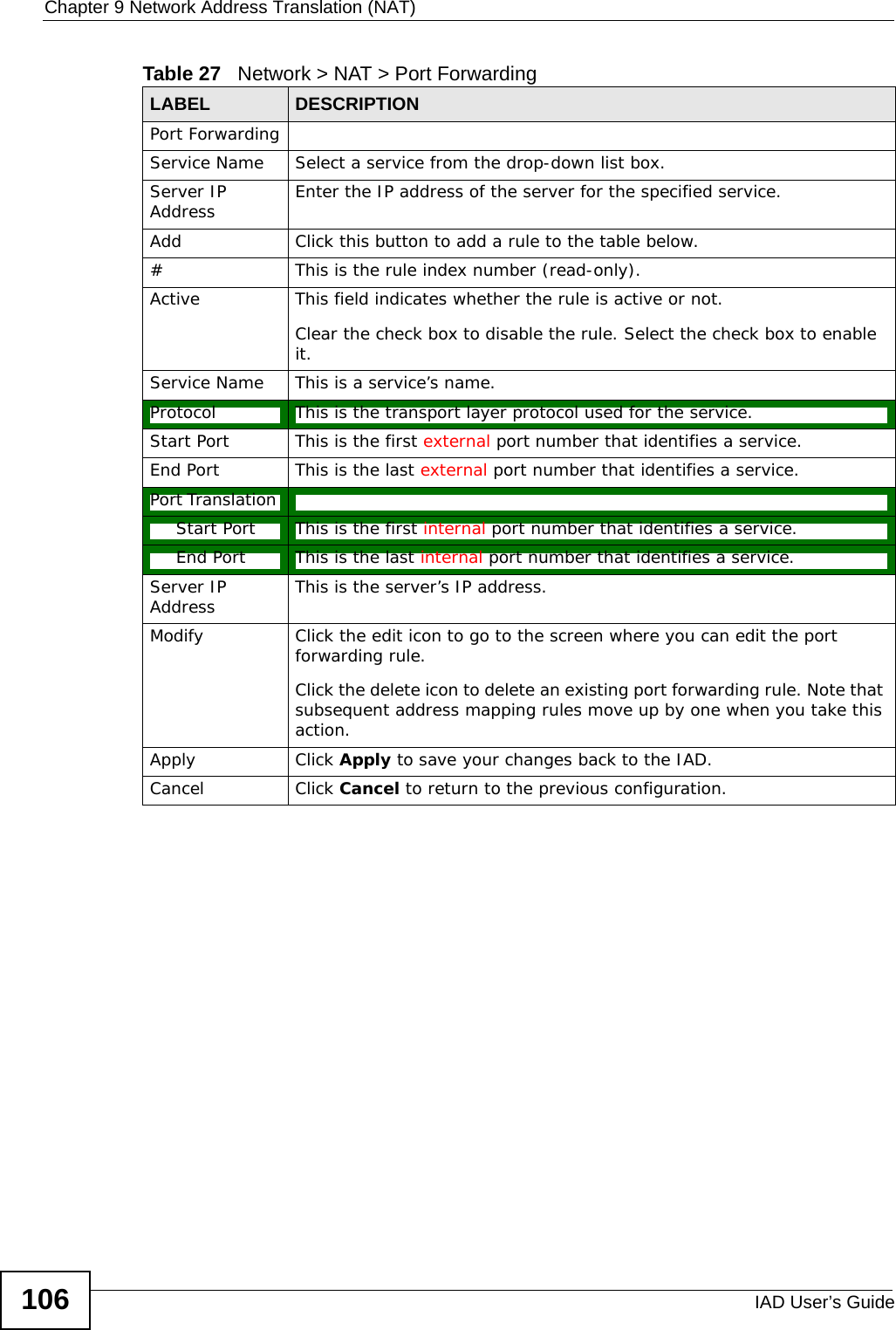
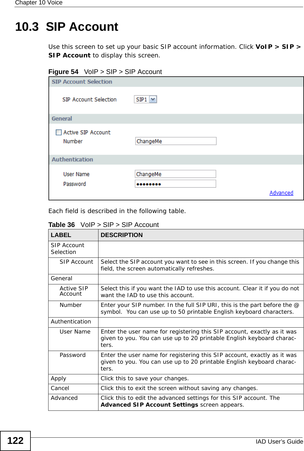
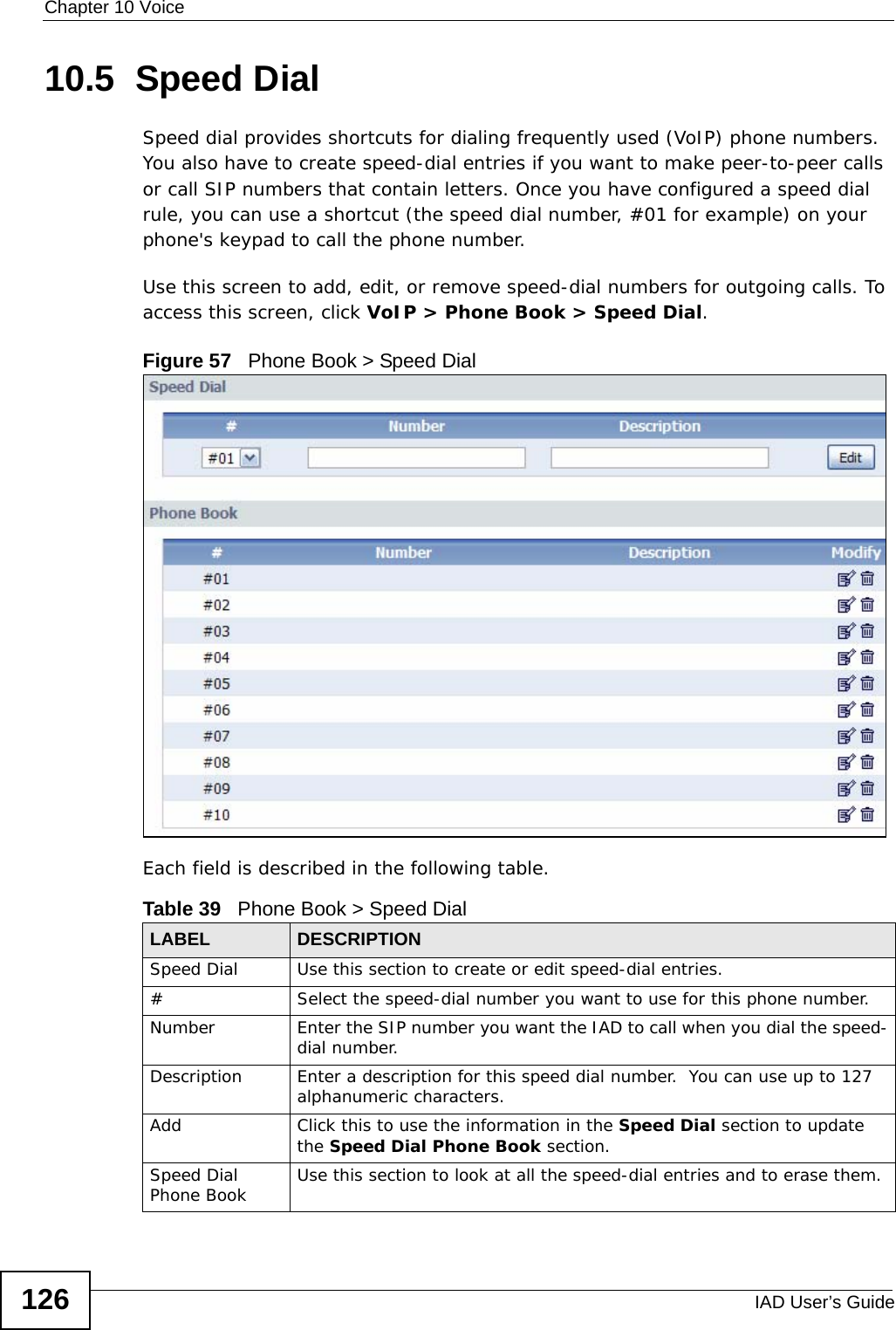
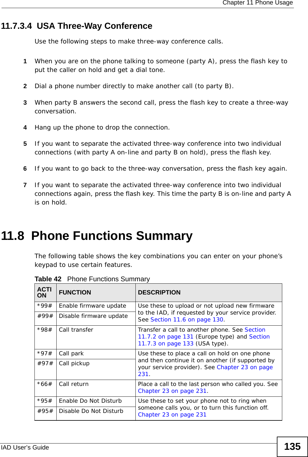
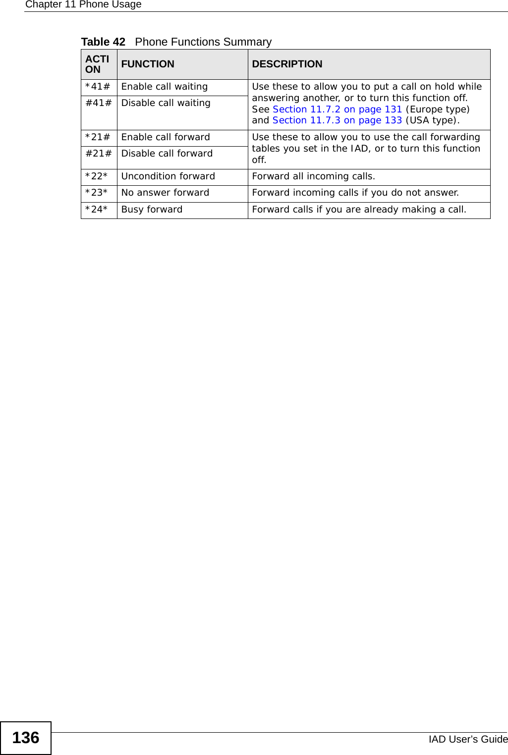
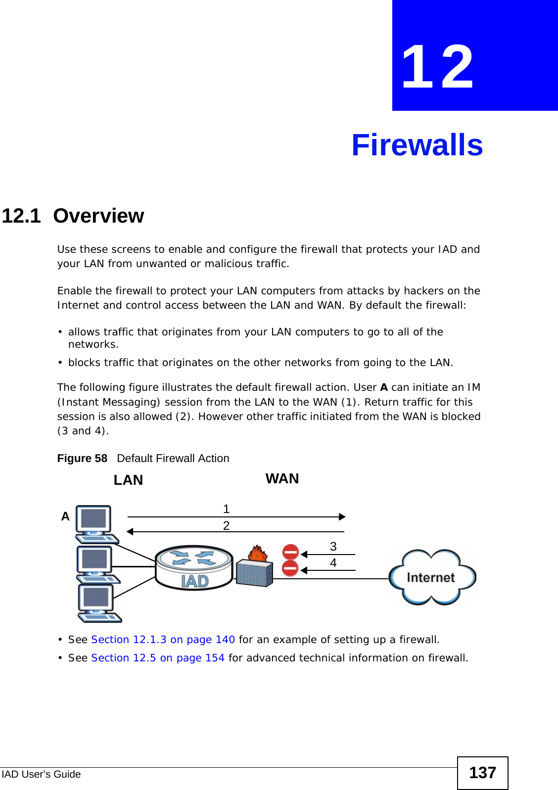
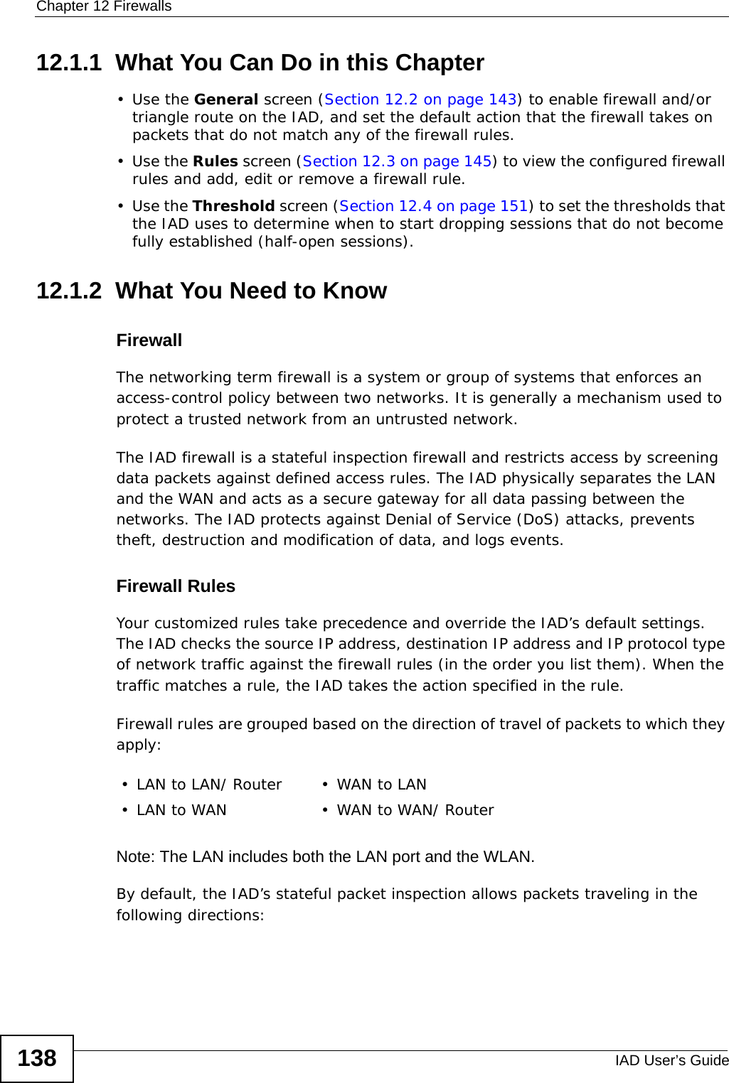
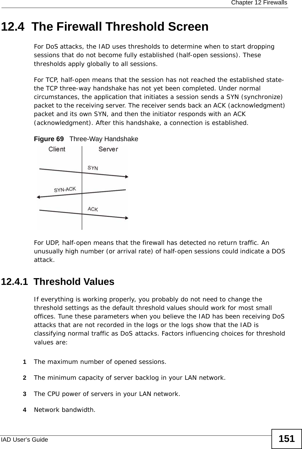
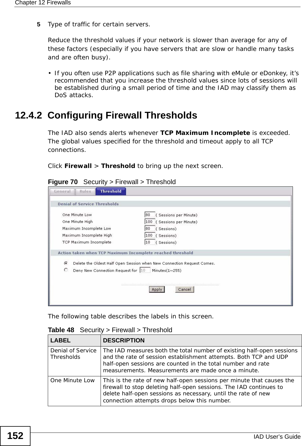
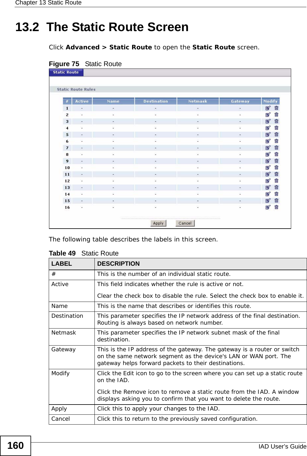
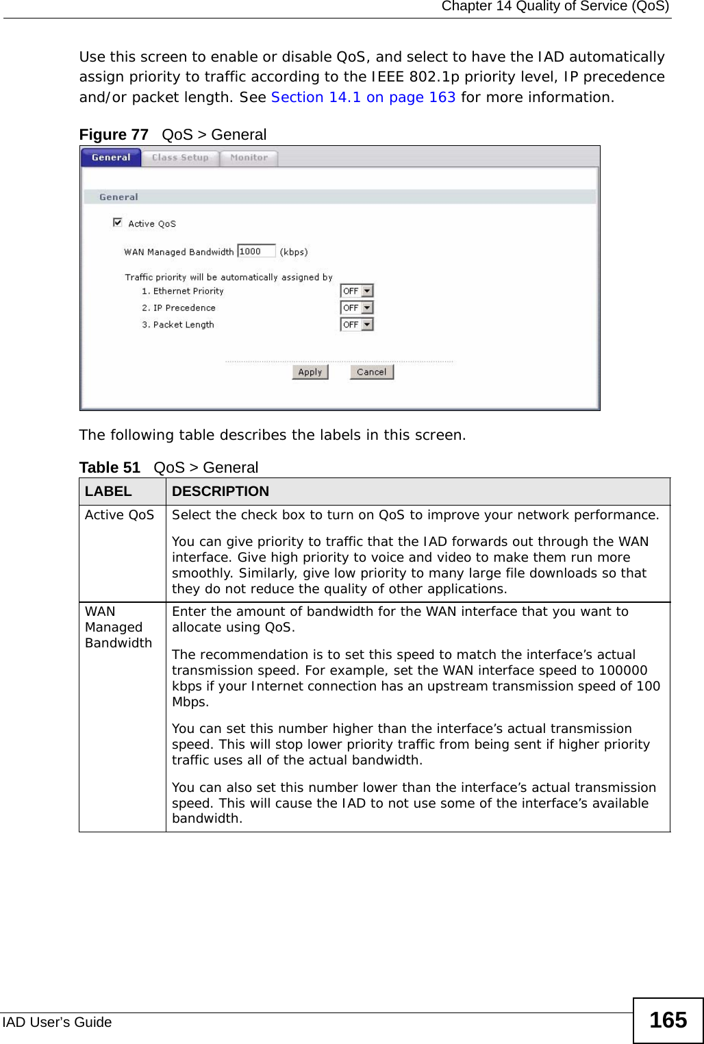
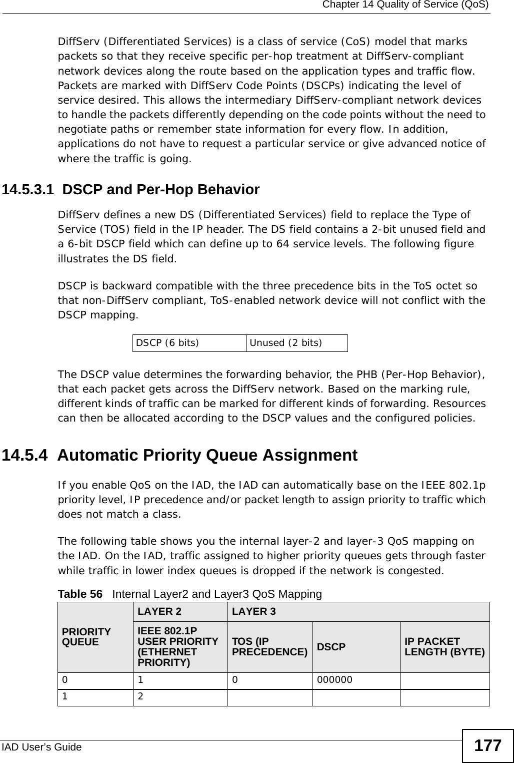
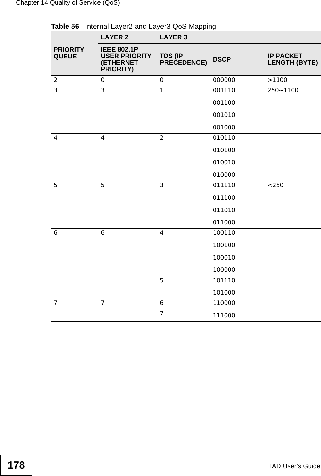
![Document ConventionsIAD User’s Guide 5Document ConventionsWarnings and NotesThese are how warnings and notes are shown in this User’s Guide. Warnings tell you about things that could harm you or your device.Note: Notes tell you other important information (for example, other things you may need to configure or helpful tips) or recommendations.Syntax Conventions• This product may be referred to as the “IAD”, the “device” or the “system” in this User’s Guide.• Product labels, screen names, field labels and field choices are all in bold font.• A key stroke is denoted by square brackets and uppercase text, for example, [ENTER] means the “enter” or “return” key on your keyboard.• “Enter” means for you to type one or more characters and then press the [ENTER] key. “Select” or “choose” means for you to use one of the predefined choices.• A right angle bracket ( > ) within a screen name denotes a mouse click. For example, Maintenance > Log > Log Setting means you first click Maintenance in the navigation panel, then the Log sub menu and finally the Log Setting tab to get to that screen.• Units of measurement may denote the “metric” value or the “scientific” value. For example, “k” for kilo may denote “1000” or “1024”, “M” for mega may denote “1000000” or “1048576” and so on.• “e.g.,” is a shorthand for “for instance”, and “i.e.,” means “that is” or “in other words”.](https://usermanual.wiki/ZyXEL-Communications/P3202HNBA.Installation-guide-1-of-2/User-Guide-1219892-Page-5.png)
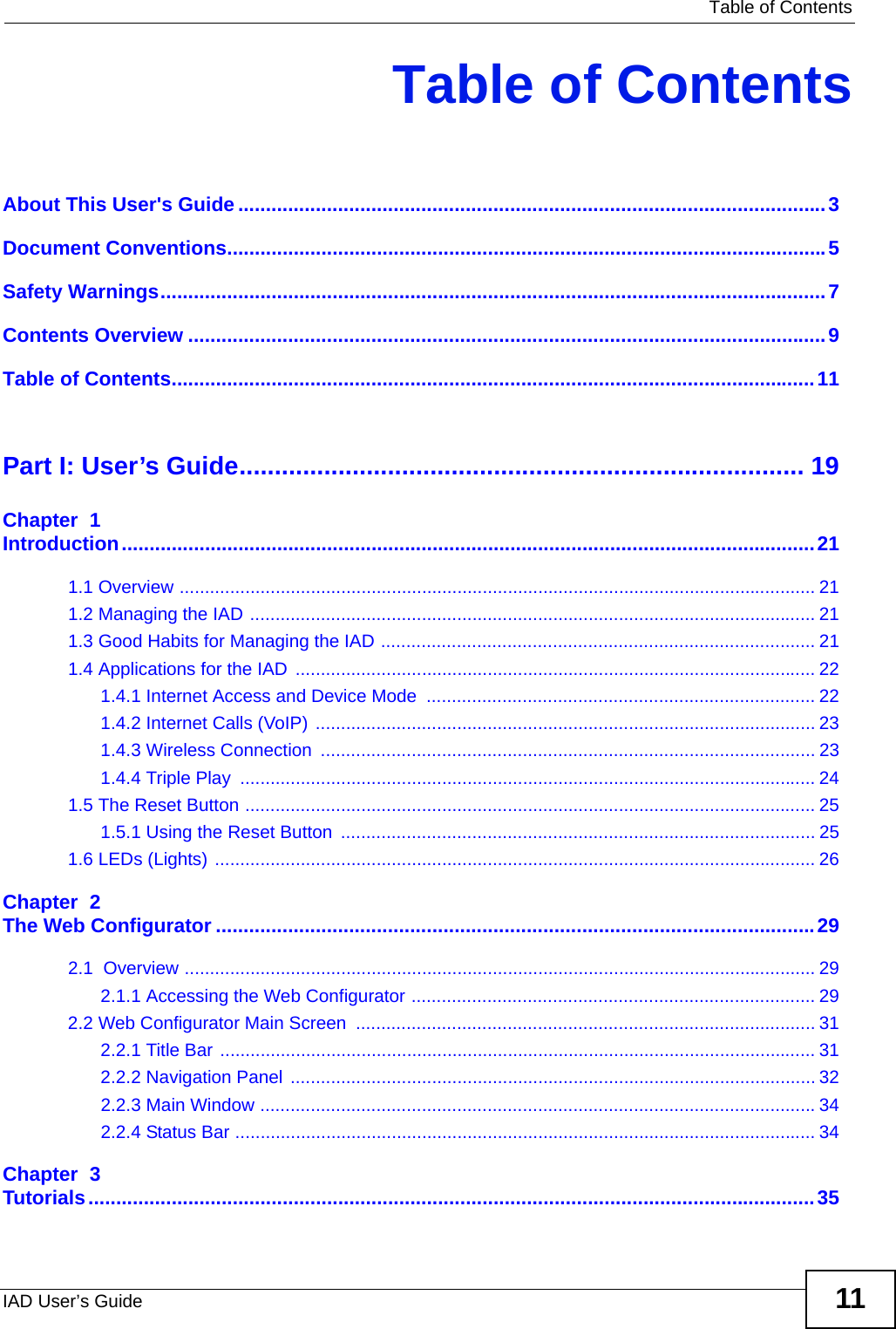
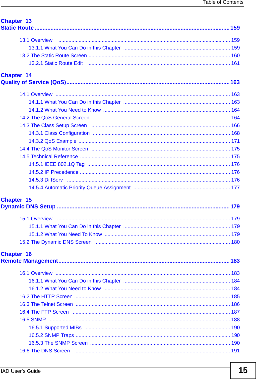


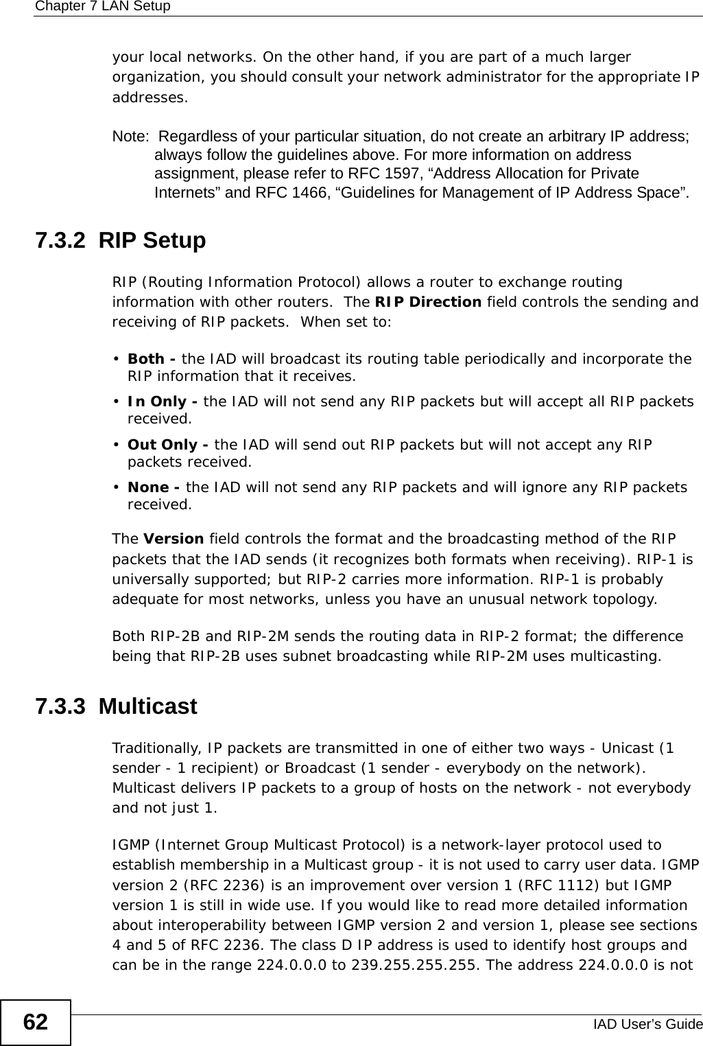
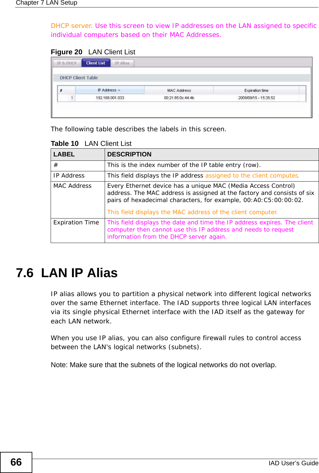

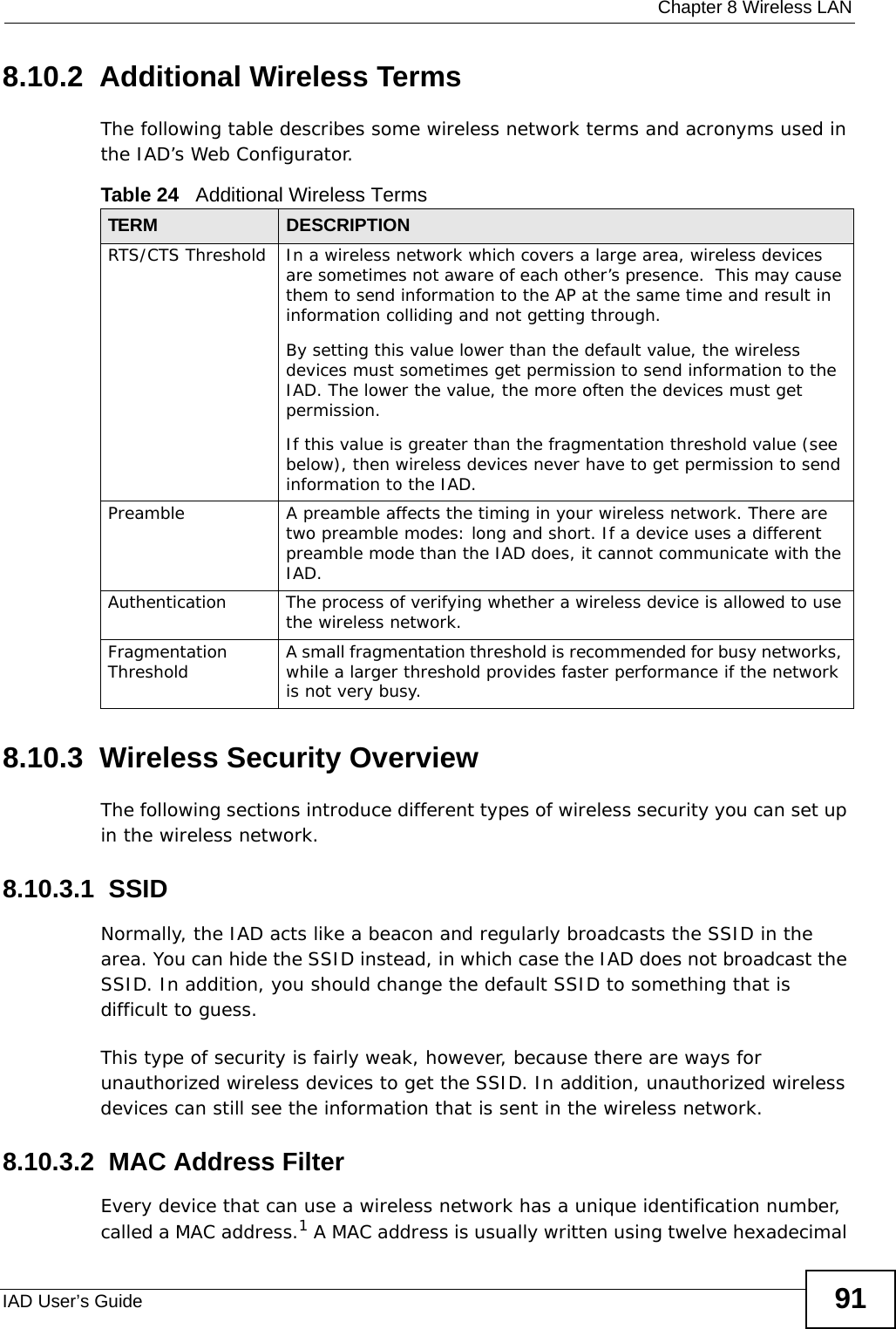
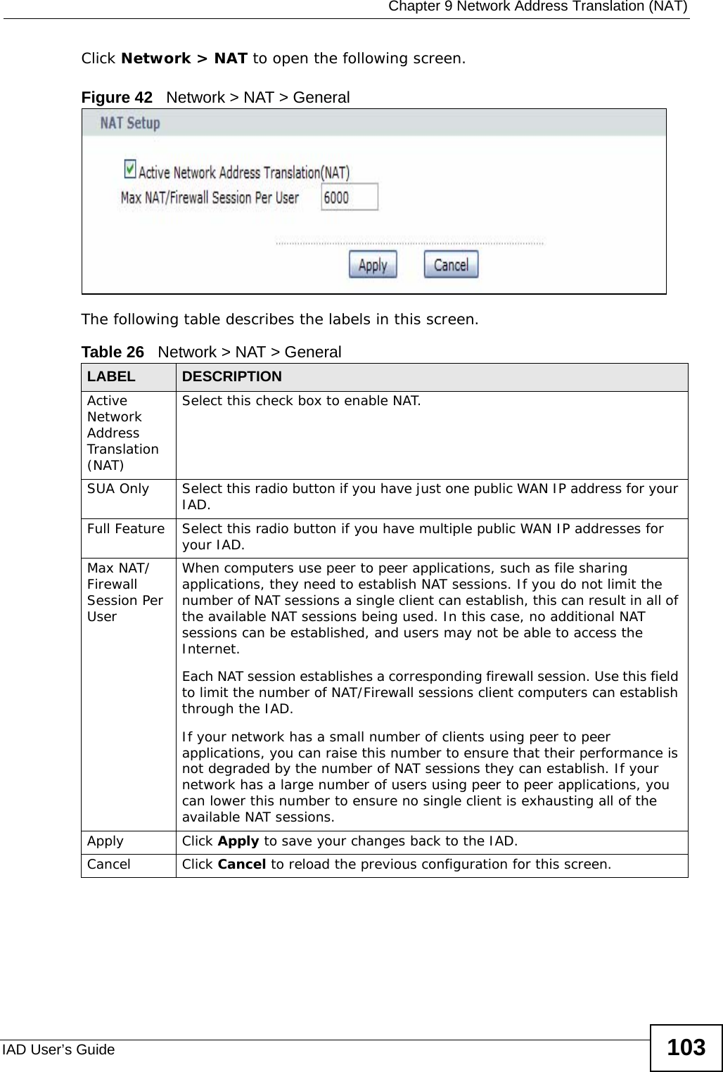
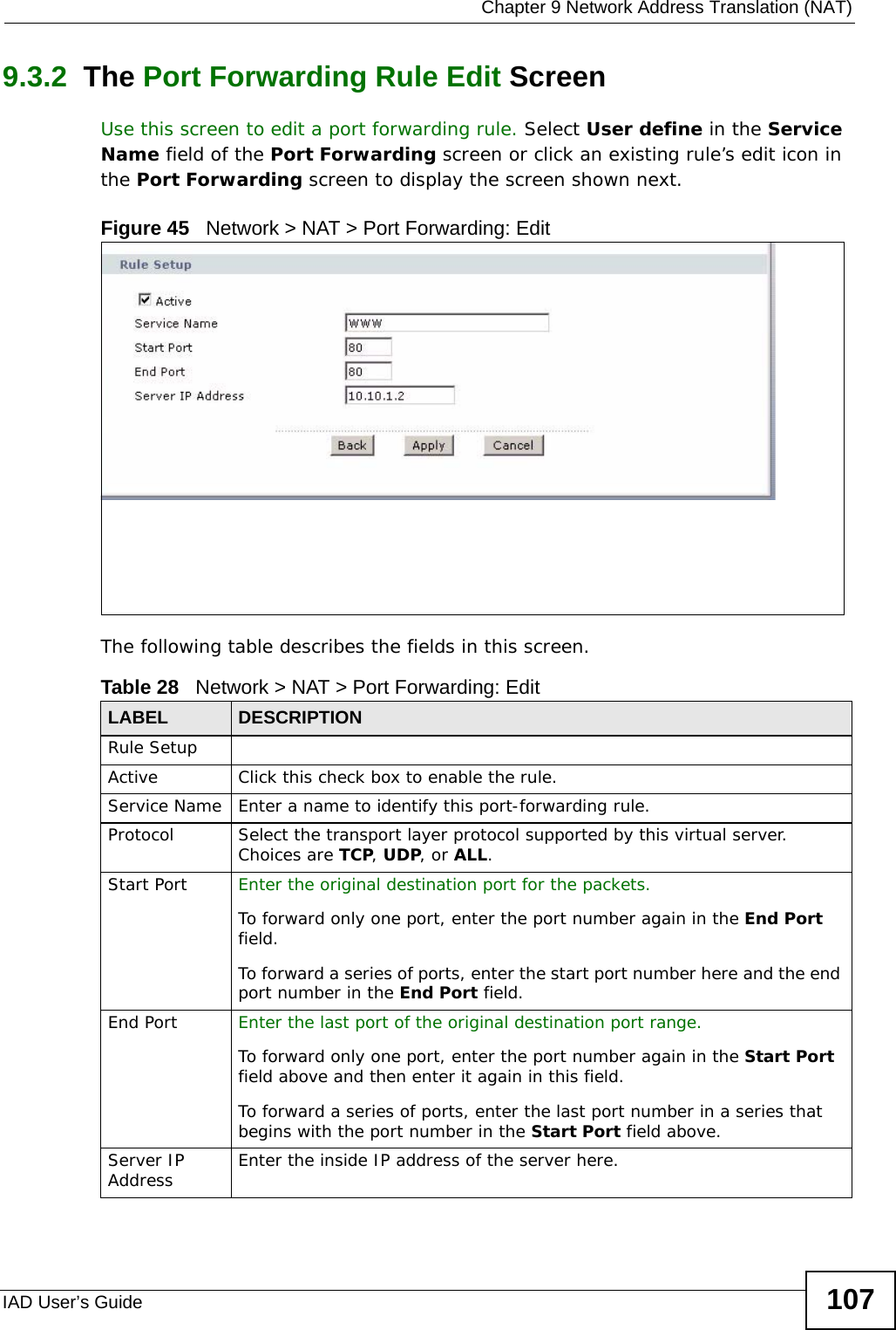
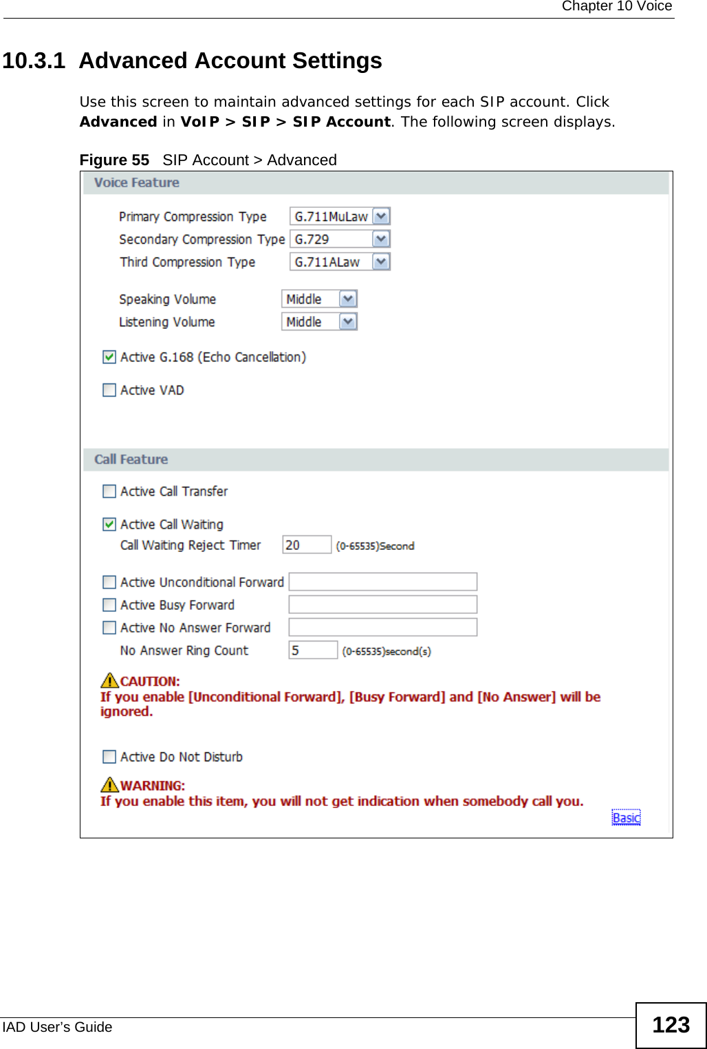
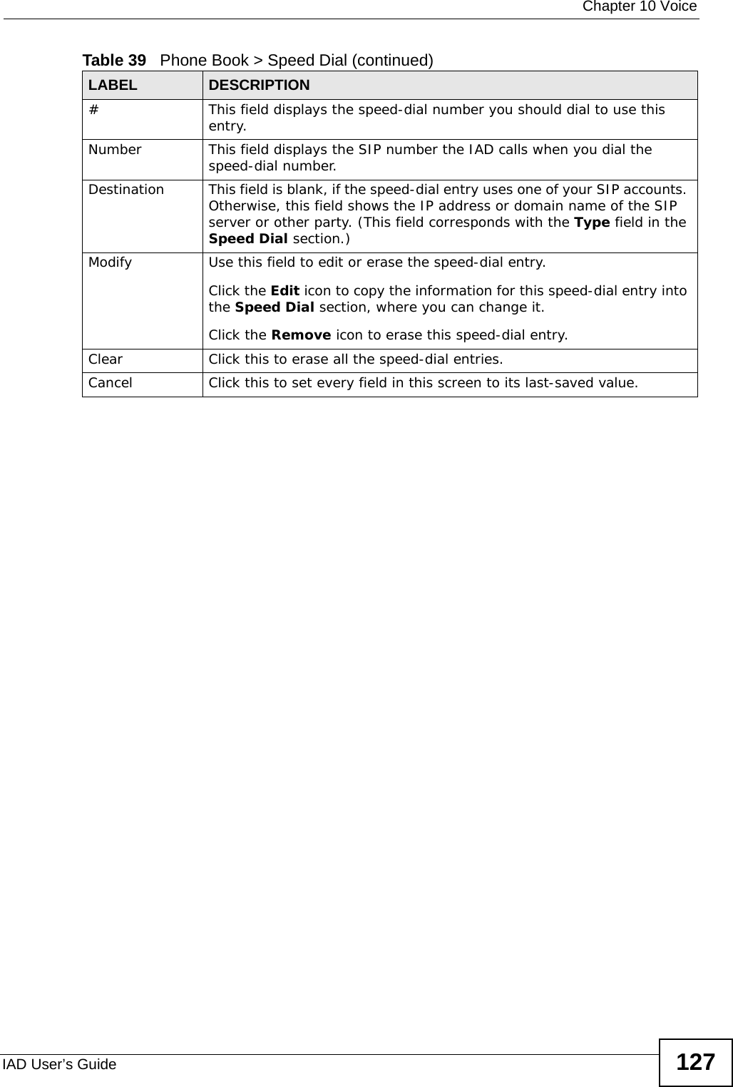


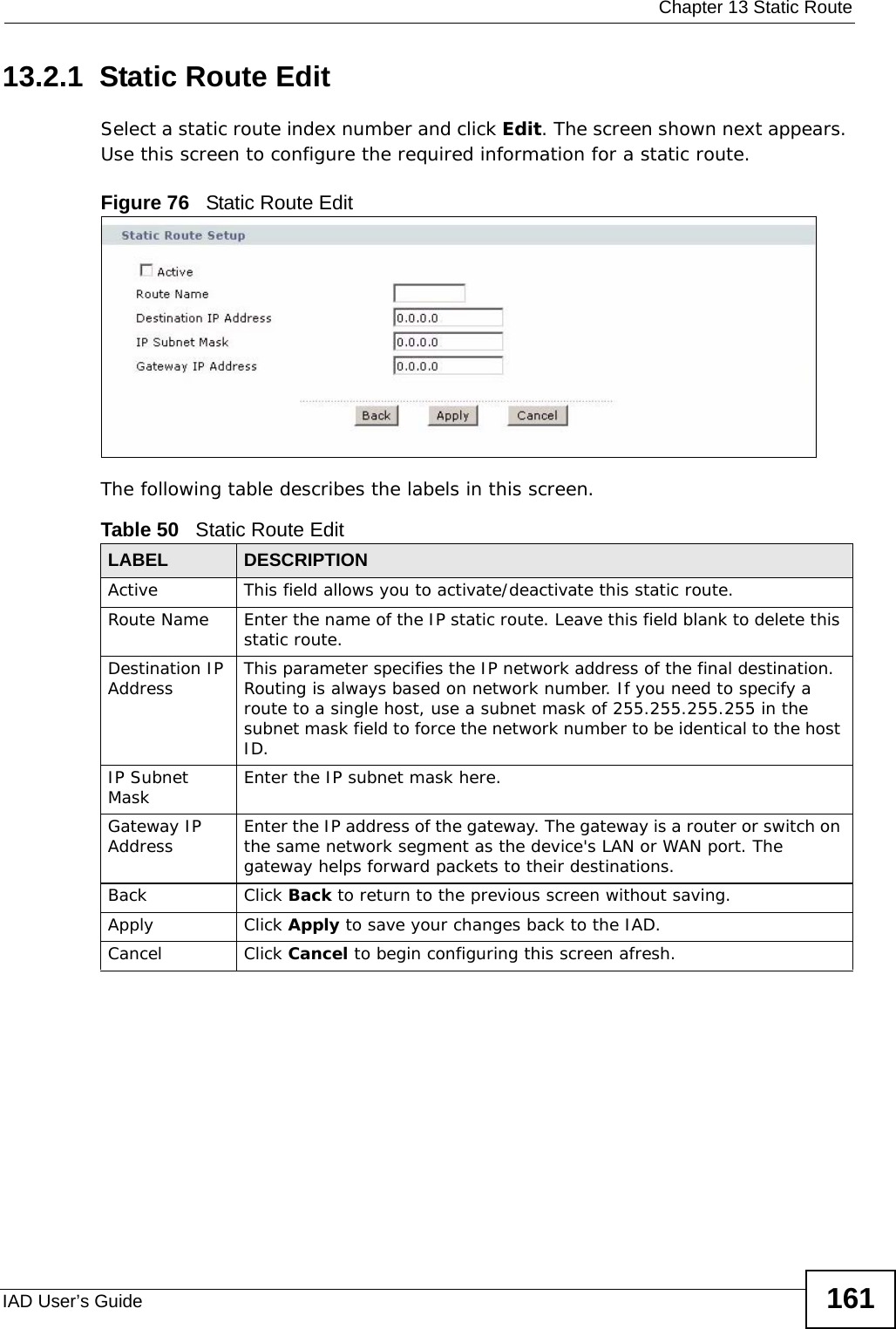


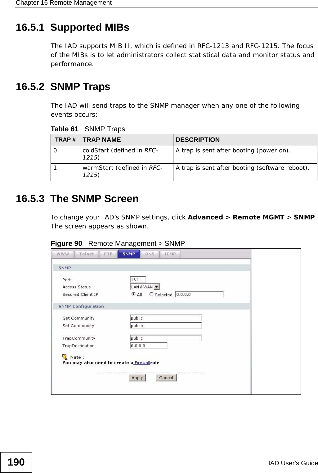
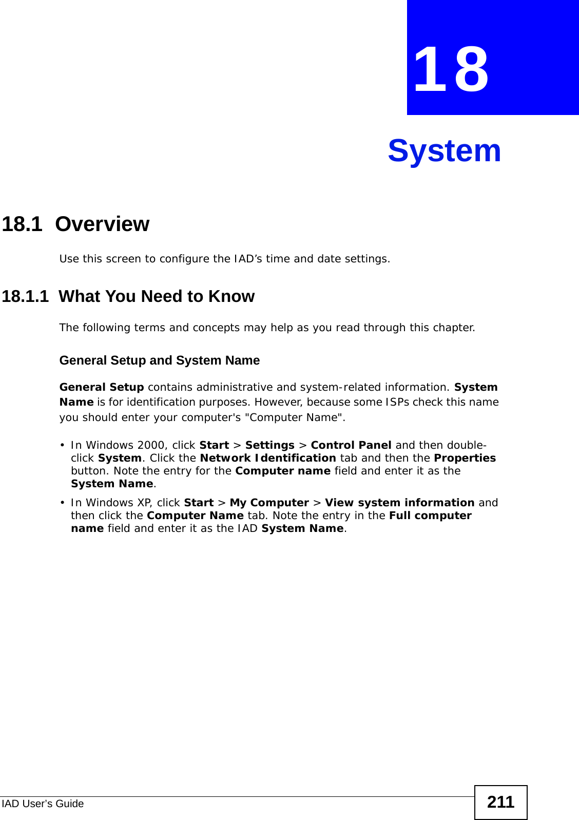

![Chapter 19 LogsIAD User’s Guide216The following table describes the fields in this screen. Table 69 View LogLABEL DESCRIPTIONDisplay The categories that you select in the Log Settings screen display in the drop-down list box.Select a category of logs to view; select All Logs to view logs from all of the log categories that you selected in the Log Settings page. Refresh Click Refresh to renew the log screen. Clear Log Click Clear Log to delete all the logs. #This field is a sequential value and is not associated with a specific entry.Time This field displays the time the log was recorded. Facility This indicates the type of connection to the IAD.Facility types are as follows:•tr069 - This indicates a log from an external auto-configuration server.•ntpclient - This indicates a log from the ntpclient.•login - This indicates a message from the login server.•udhcpc - This indicates a log message from the device’s DHCP server.•dnsmasq - This indicates a log message from the device’s DNS forwarder.•PPPD - This indicates a log message from the device’s Point-to-Point Protocol daemon.•kernel - This indicates a log message related to the device’s Central Processing Unit (CPU), memory, and I/O ports.•OMCI - This indicates a log message about the OpenManage Client Instrumentation.•VoIP - This indicates a log a message from the SIP server.Level This indicates the log severity.Message This field states the reason for the log.First Click this to cycle to the first page of logs.Previous Click this to cycle to the previous page of logs.Page This indicates which page you are on, out of how many. You can enter a page number here and press [Enter] to jump directly to that page.Next Click this to cycle to the next page of logs.Last Click this to cycle to the last page of logsRefresh Click this to refresh the logs screen.](https://usermanual.wiki/ZyXEL-Communications/P3202HNBA.Installation-guide-1-of-2/User-Guide-1219892-Page-216.png)
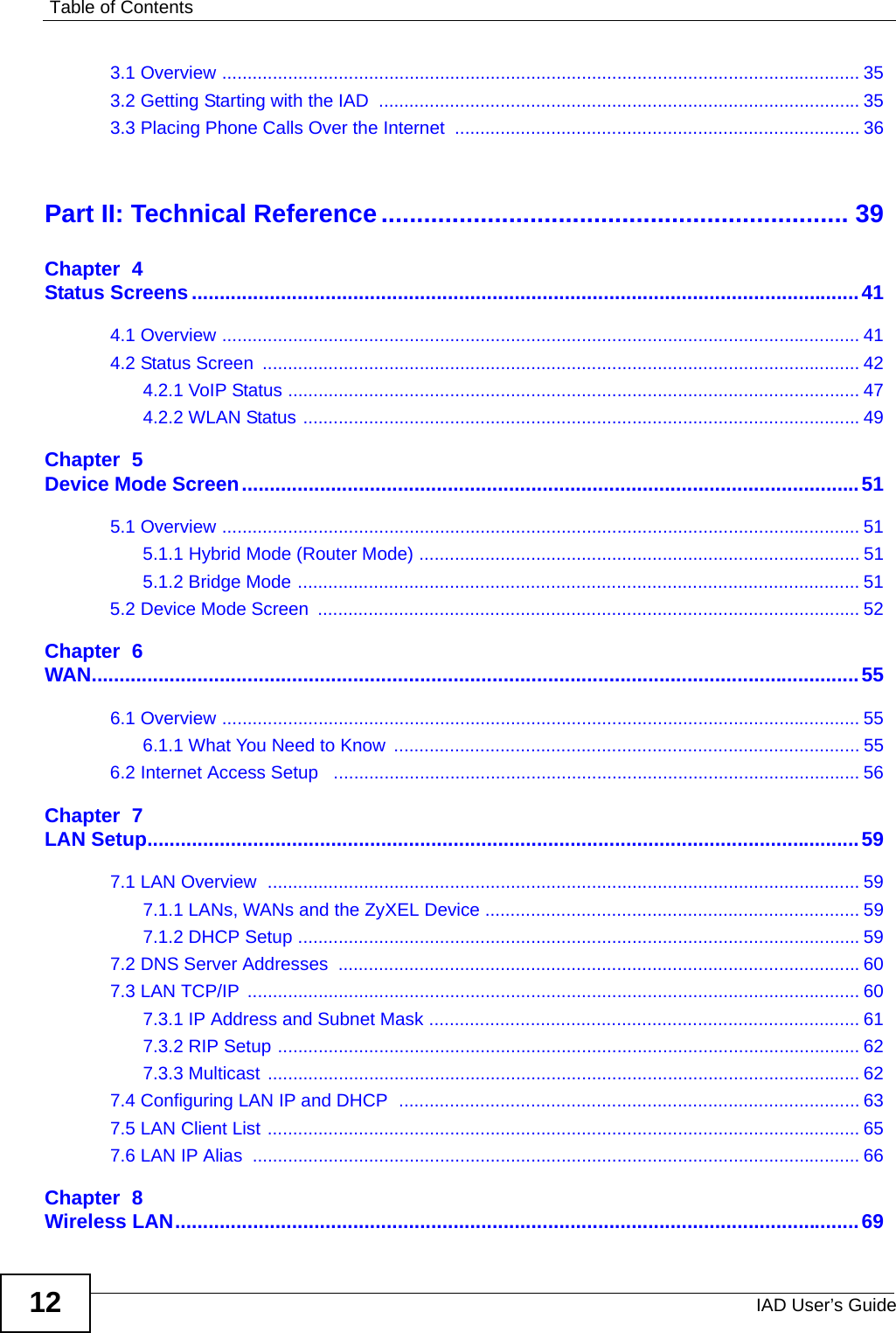
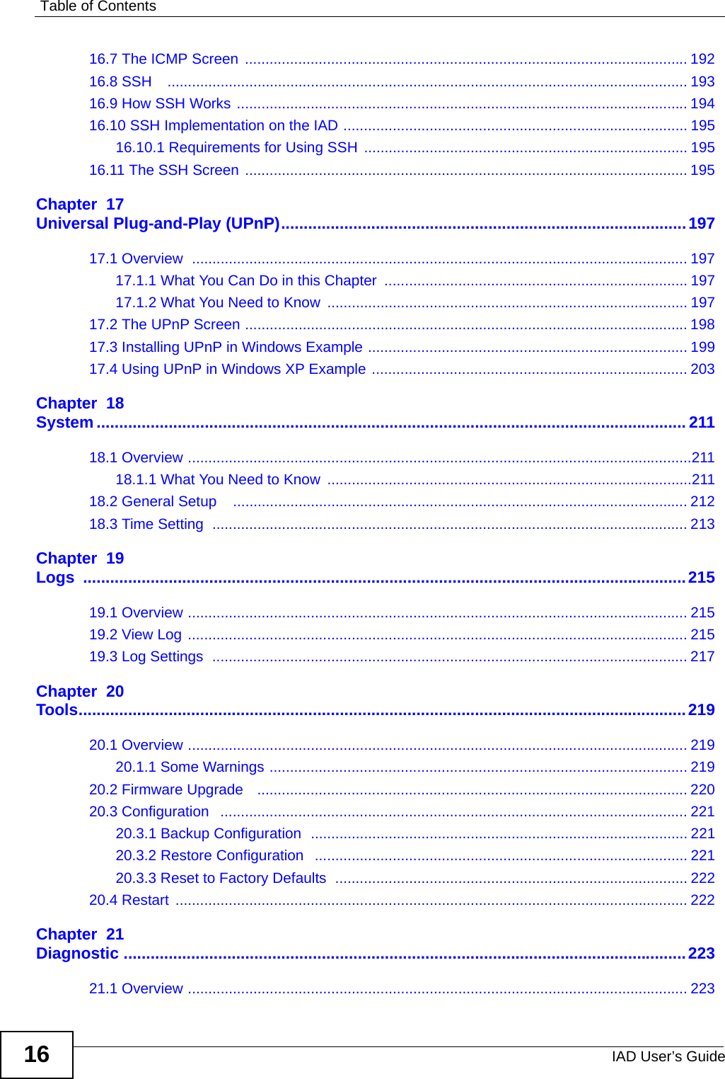
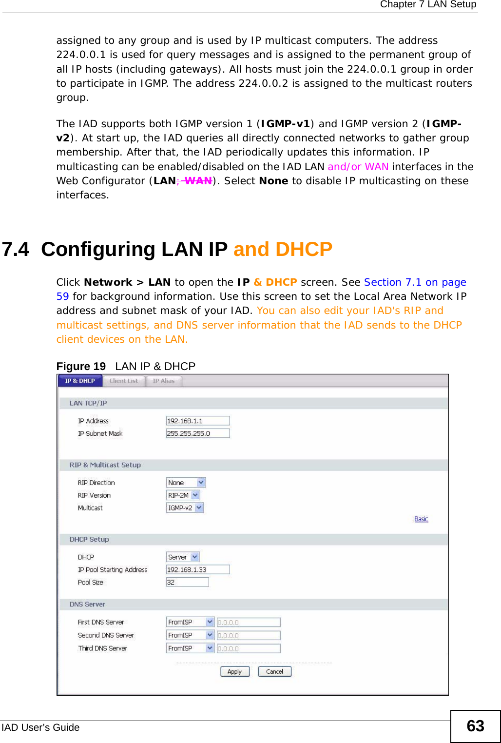
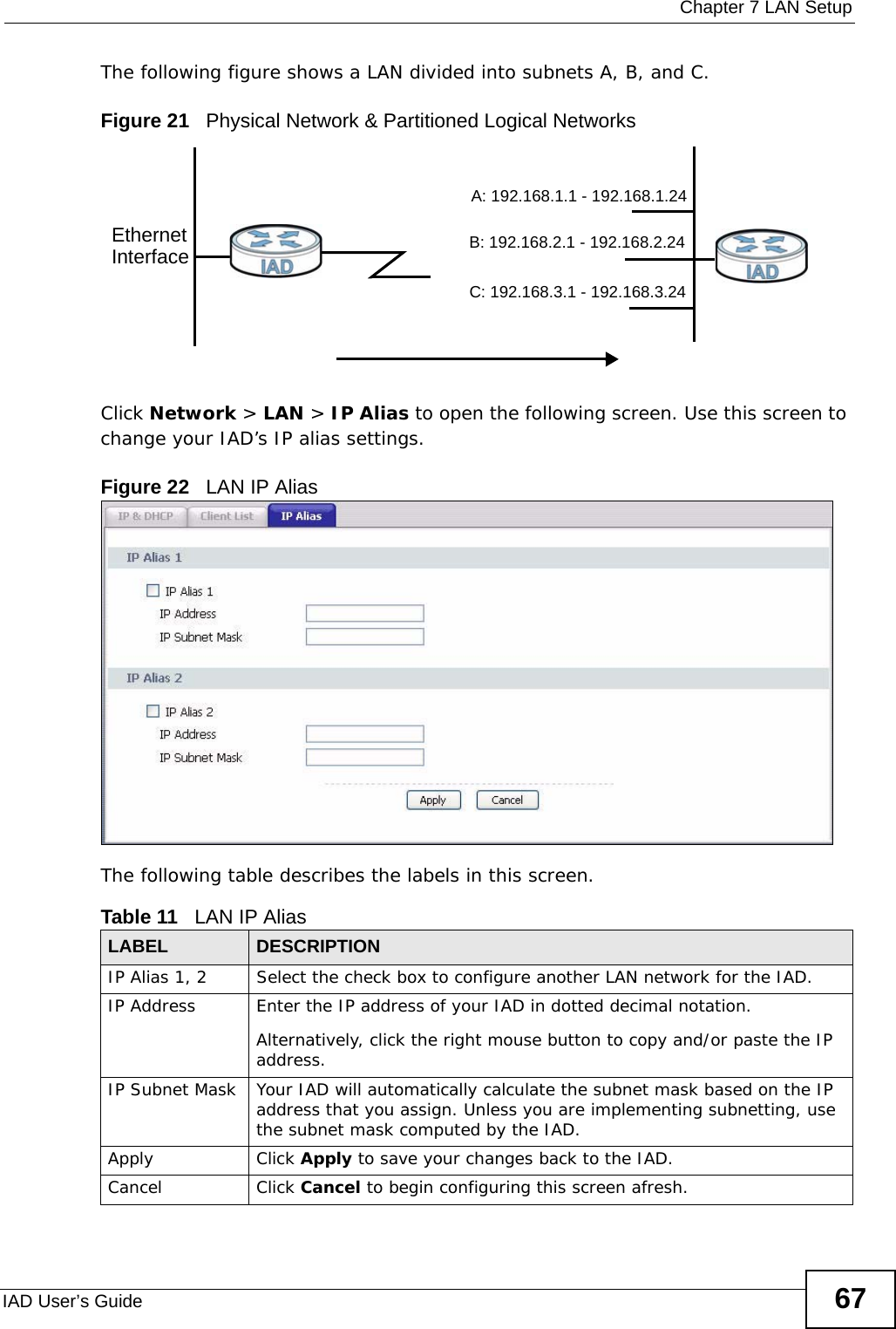
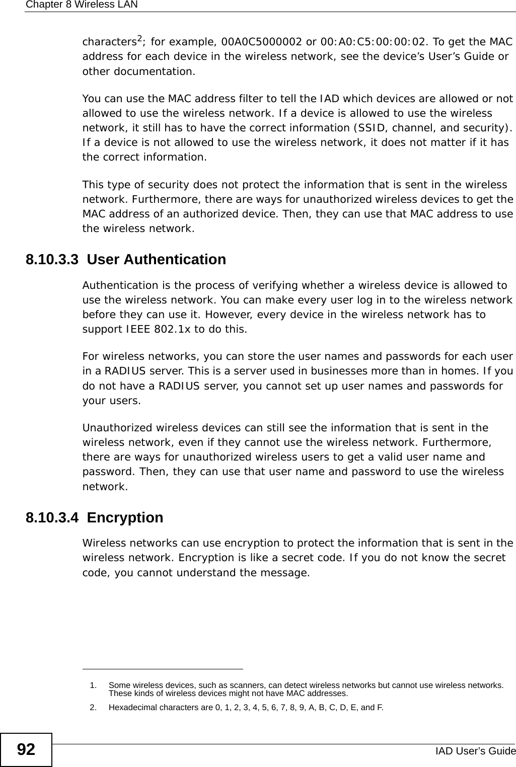
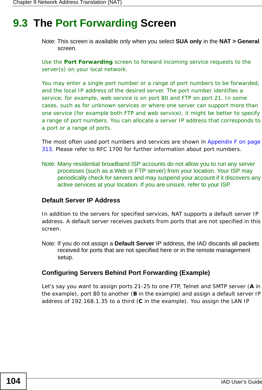
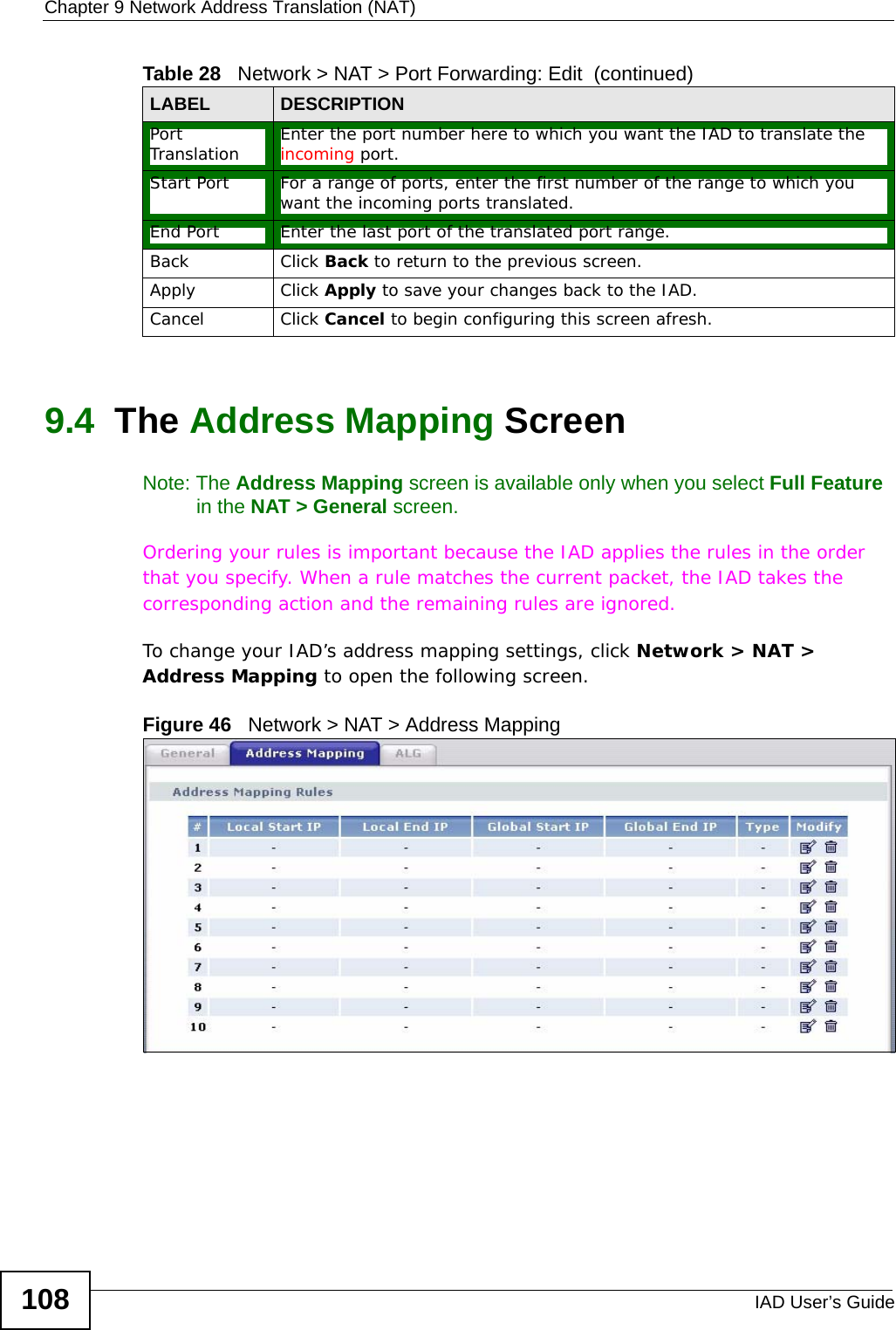
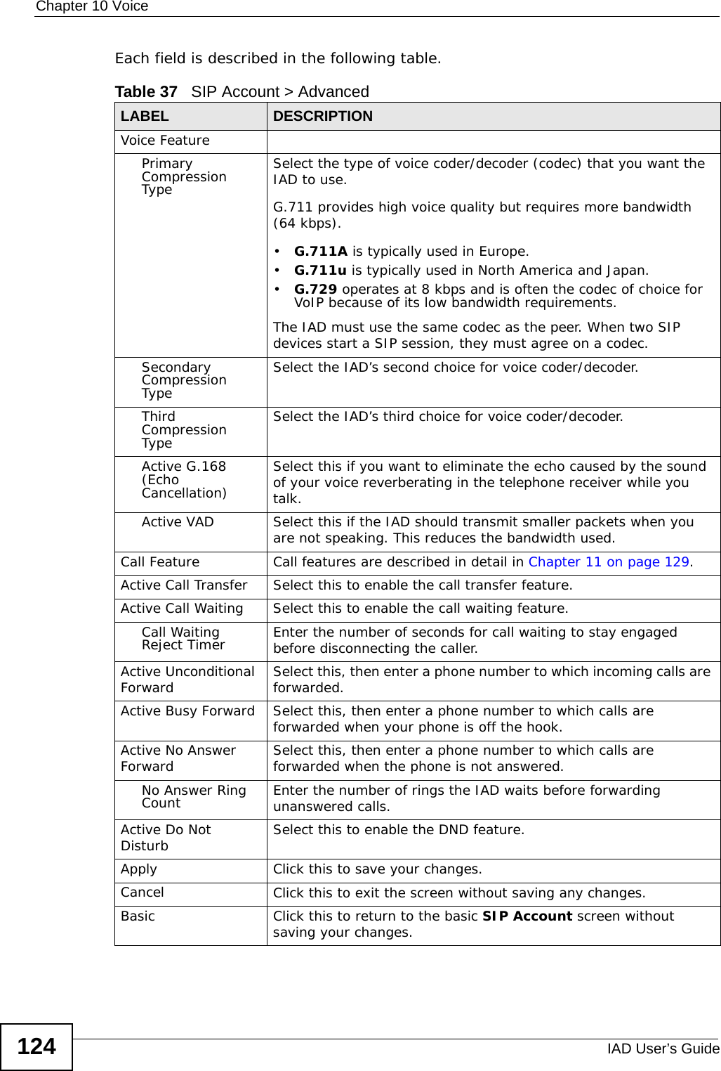
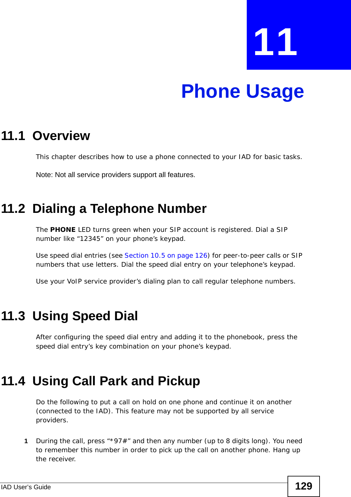
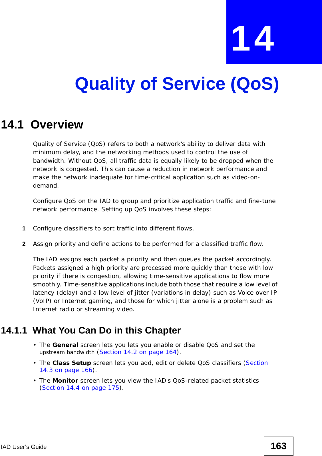
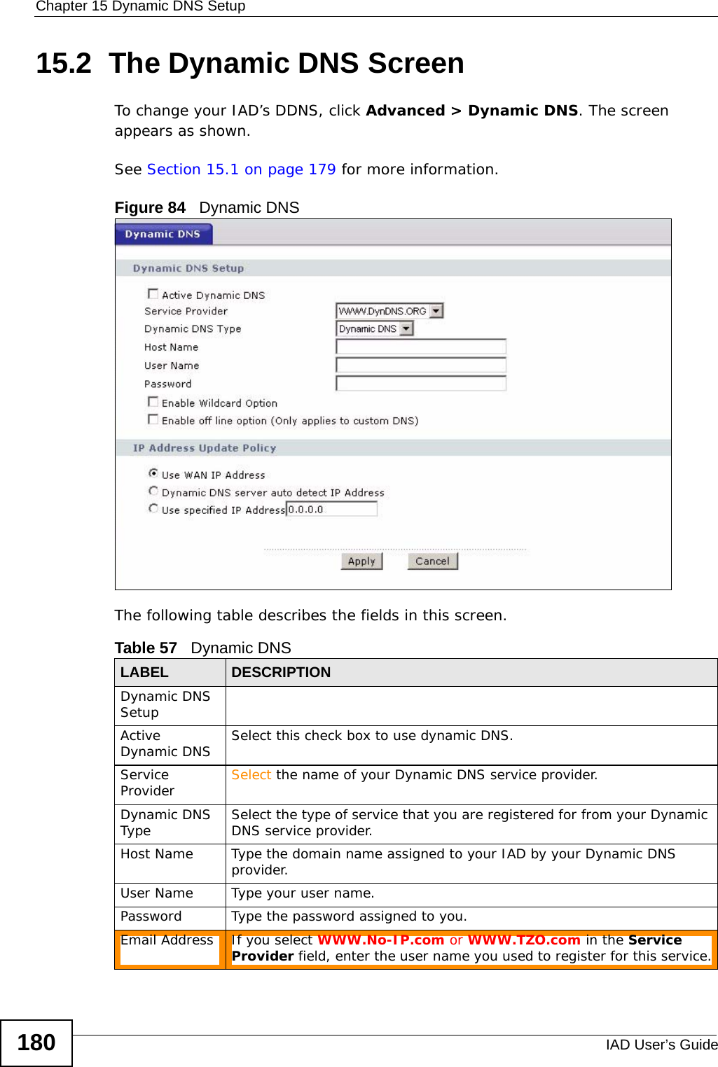
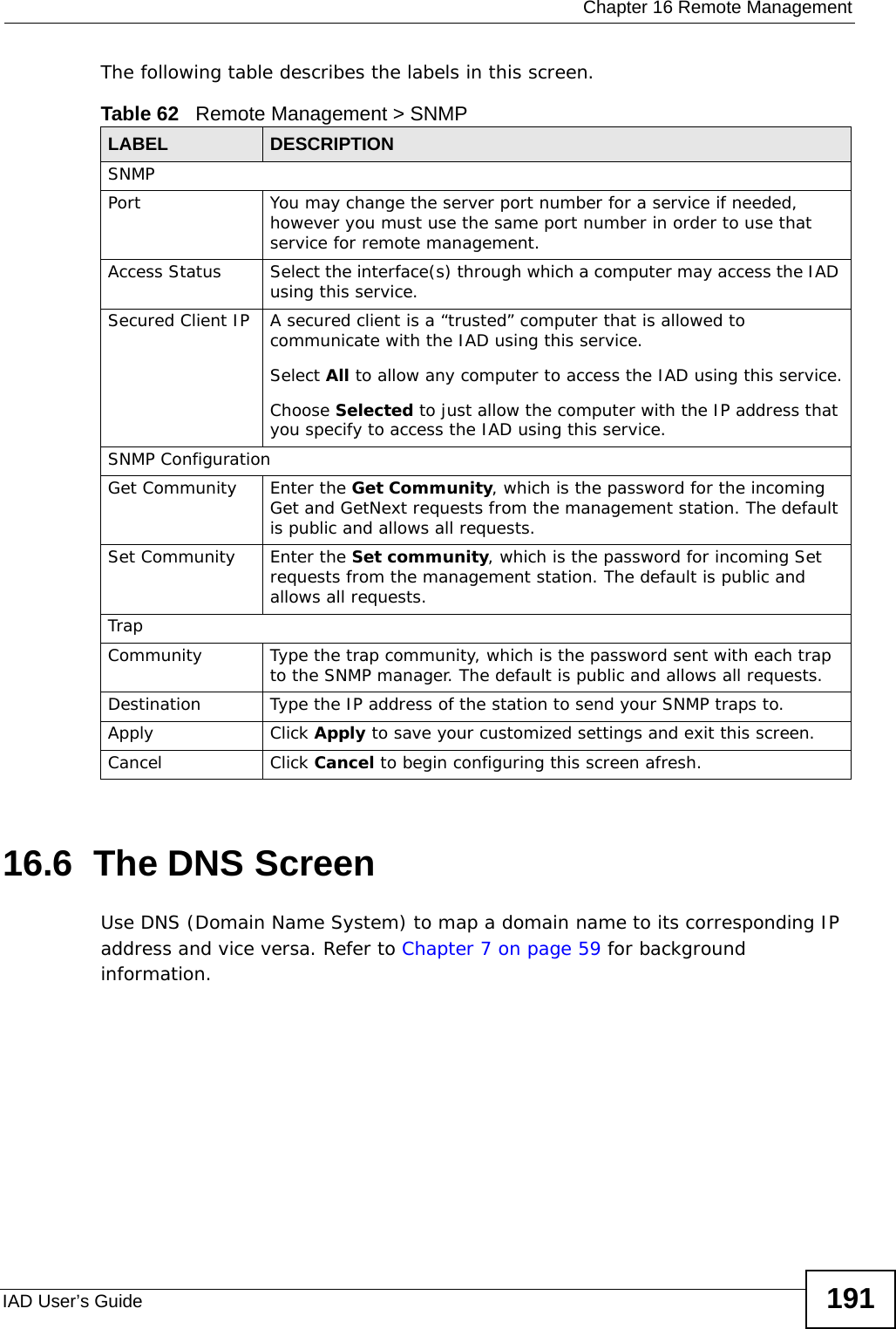
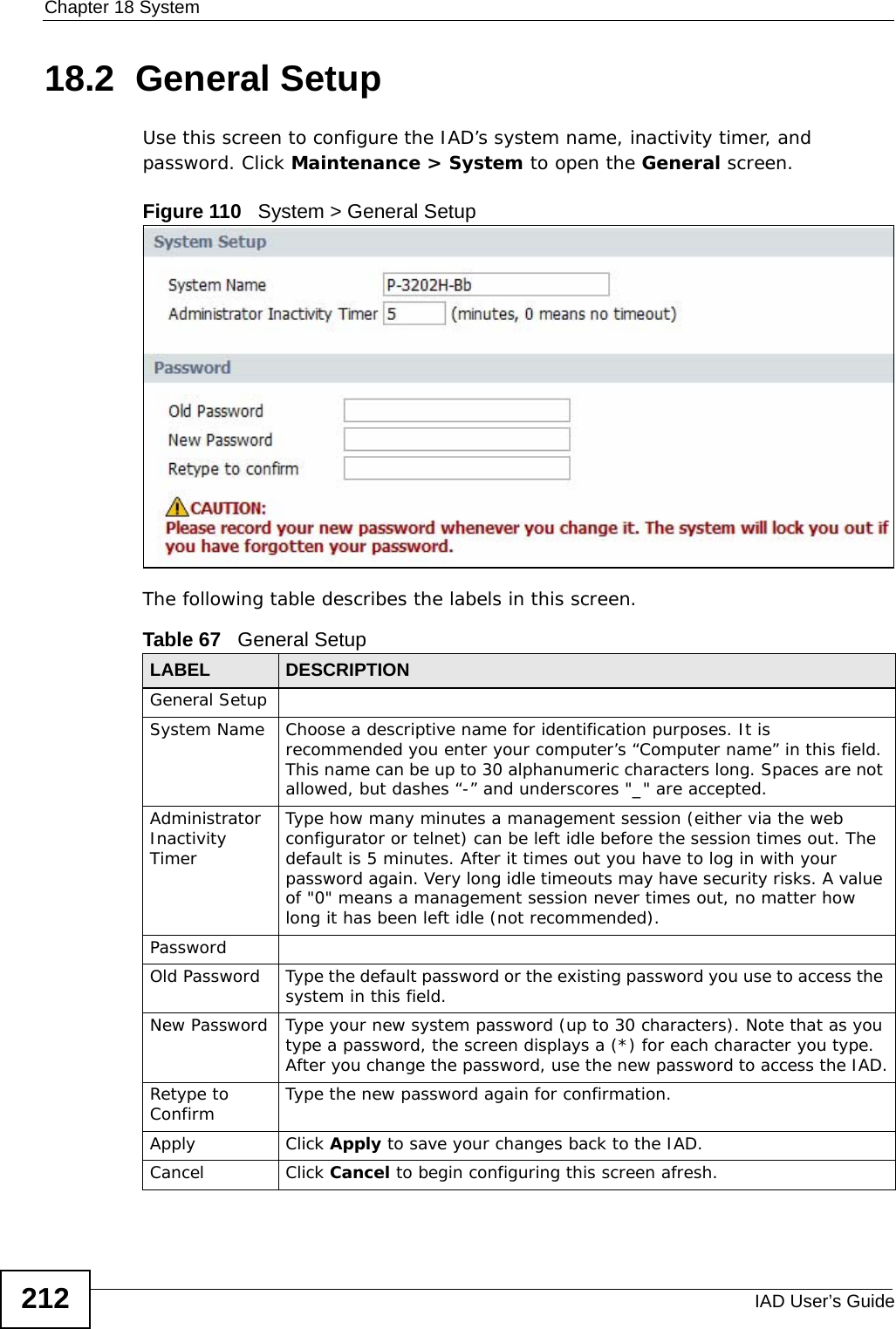
![Chapter 19 LogsIAD User’s Guide 21719.3 Log Settings Use this screen to configure which logs to display on the View Logs screen (see Chapter 19 on page 215). Click Maintenance > Logs > Log Settings.Figure 113 Log SettingsThe following table describes the fields in this screen. Table 70 Log SettingsLABEL DESCRIPTIONActive Log[Log Type] Select the type of log you want to be displayed on the View Logs screen.Apply Click Apply to save your customized settings and exit this screen. Cancel Click Cancel to return to the previously saved settings.](https://usermanual.wiki/ZyXEL-Communications/P3202HNBA.Installation-guide-1-of-2/User-Guide-1219892-Page-217.png)
![Chapter 22 TroubleshootingIAD User’s Guide 227• If you changed the IP address and have forgotten it, see the troubleshooting suggestions for I forgot the IP address for the IAD.2Check the hardware connections, and make sure the LEDs are behaving as expected. See the Quick Start Guide.3Make sure your Internet browser does not block pop-up windows and has JavaScripts and Java enabled. See Appendix C on page 275.4Reset the device to its factory defaults, and try to access the IAD with the default IP address. See Section 1.5 on page 25. 5If the problem continues, contact the network administrator or vendor, or try one of the advanced suggestions.I can see the Login screen, but I cannot log in to the IAD.1Make sure you have entered the user name and password correctly. The default user name is admin. These fields are case-sensitive, so make sure [Caps Lock] is not on. 2You cannot log in to the web configurator while someone is using Telnet to access the IAD. Log out of the IAD in the other session, or ask the person who is logged in to log out. 3Turn the IAD off and on. 4If this does not work, you have to reset the device to its factory defaults. See Section 22.2 on page 225.22.4 Internet AccessI cannot access the Internet.1Check the hardware connections, and make sure the LEDs are behaving as expected. See the Quick Start Guide and Section 1.6 on page 26. 2Make sure you entered your ISP account information correctly in the wizard. These fields are case-sensitive, so make sure [Caps Lock] is not on.](https://usermanual.wiki/ZyXEL-Communications/P3202HNBA.Installation-guide-1-of-2/User-Guide-1219892-Page-227.png)

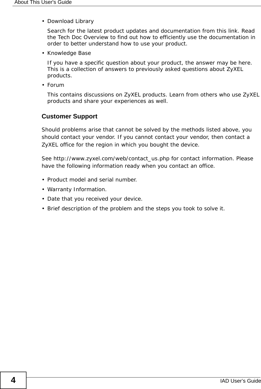
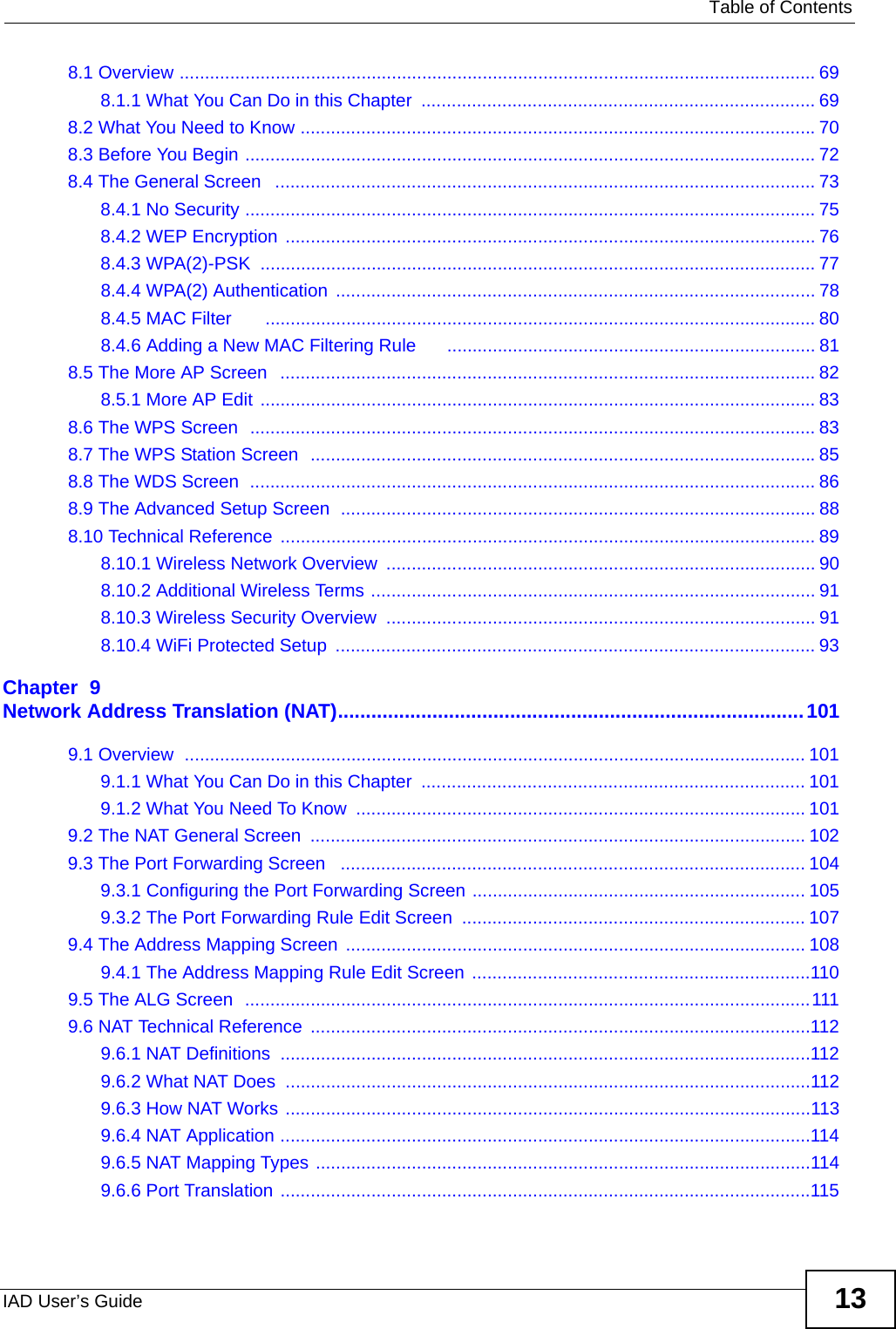
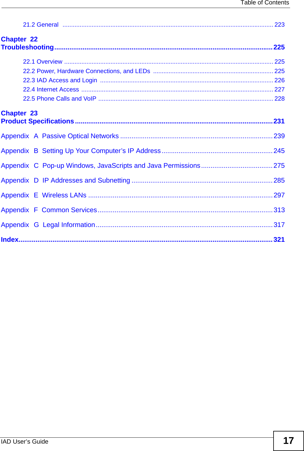
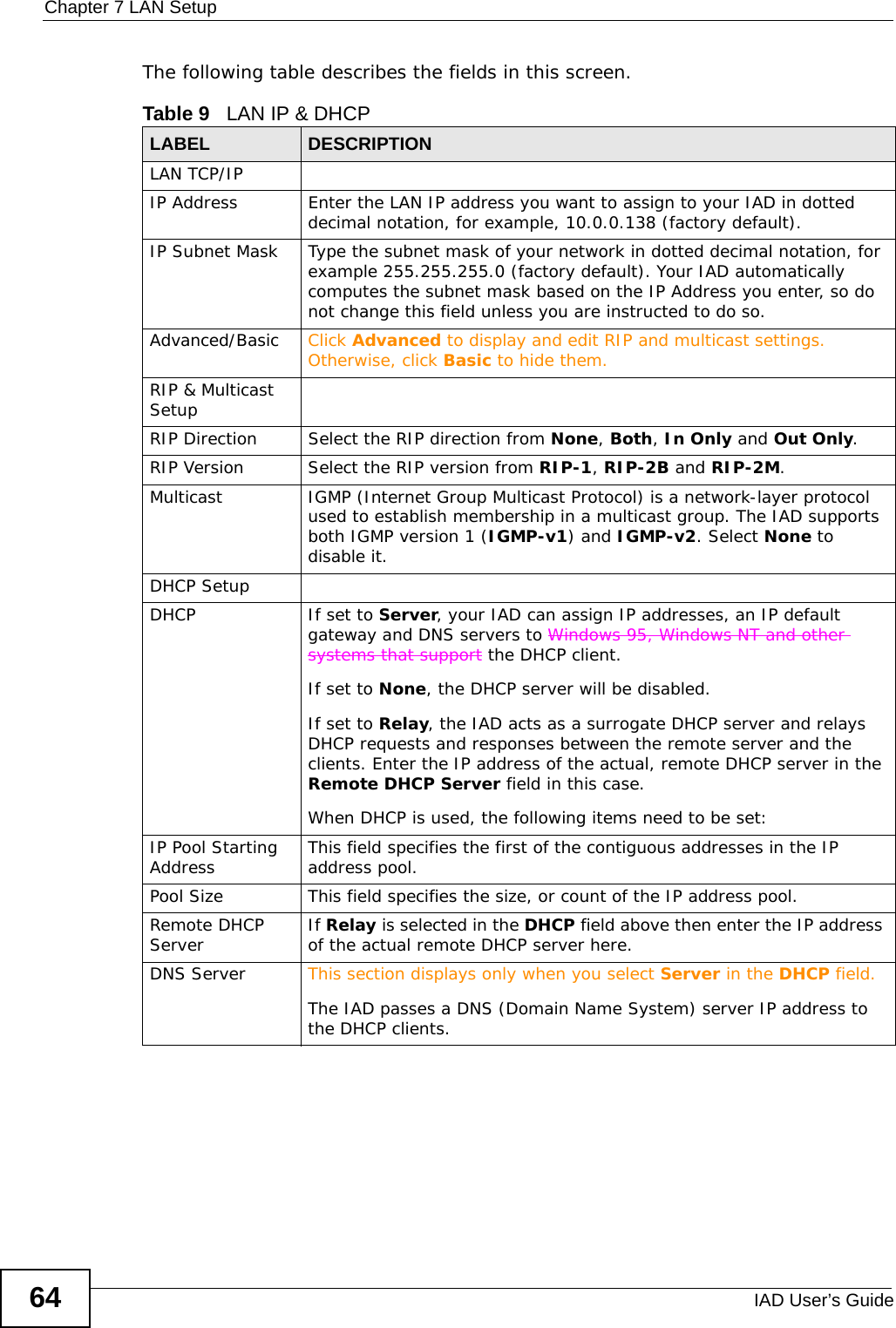
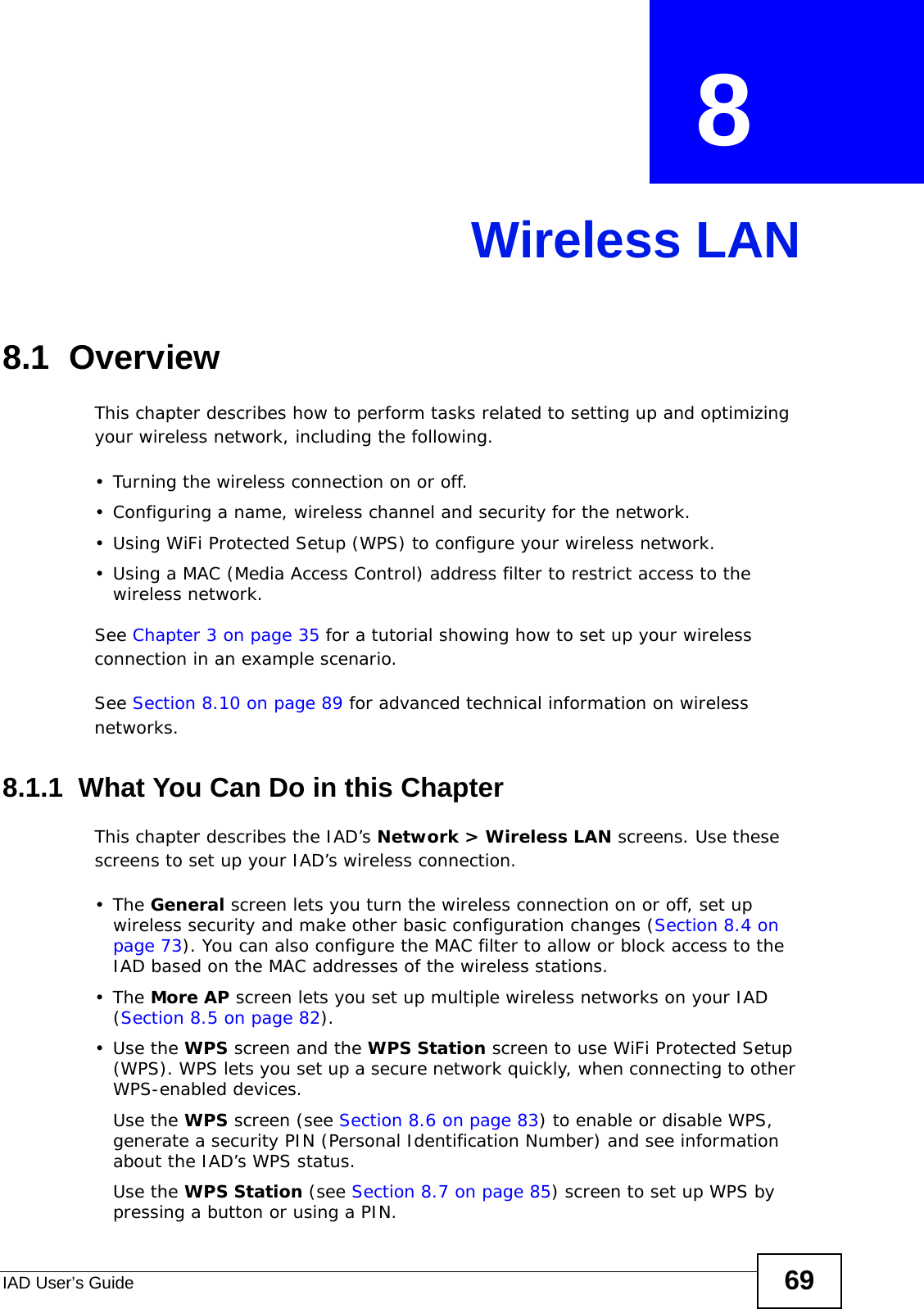
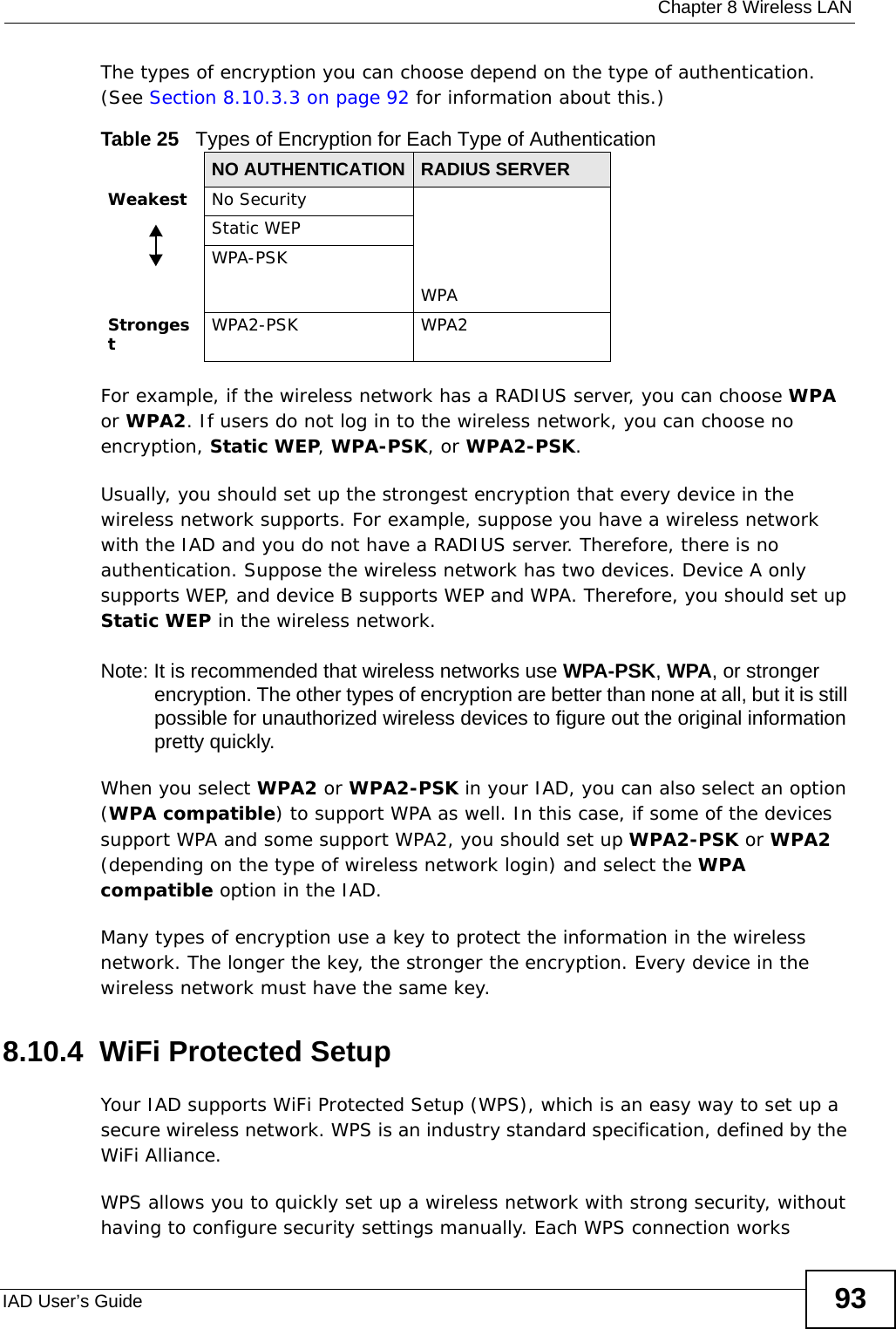
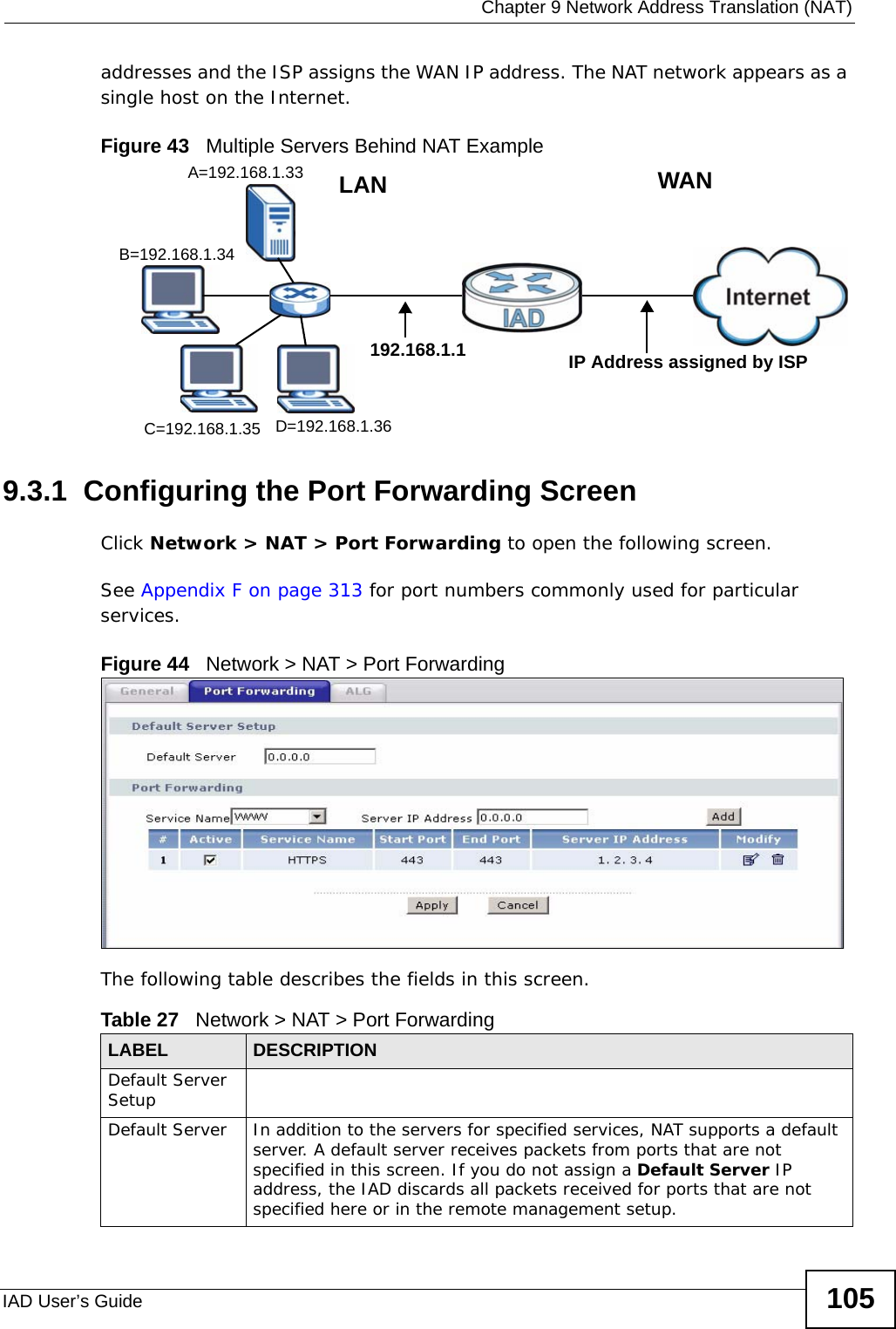
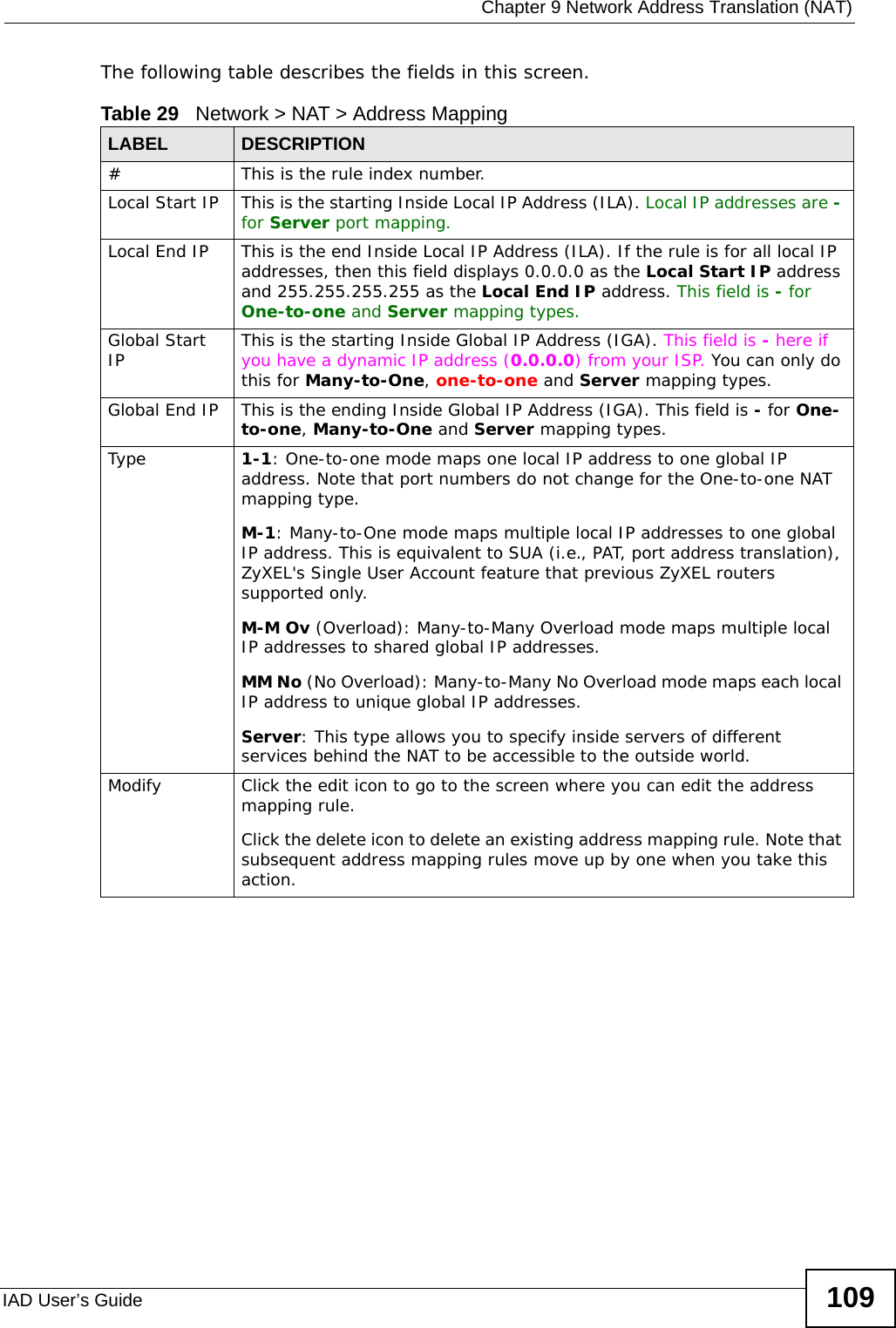
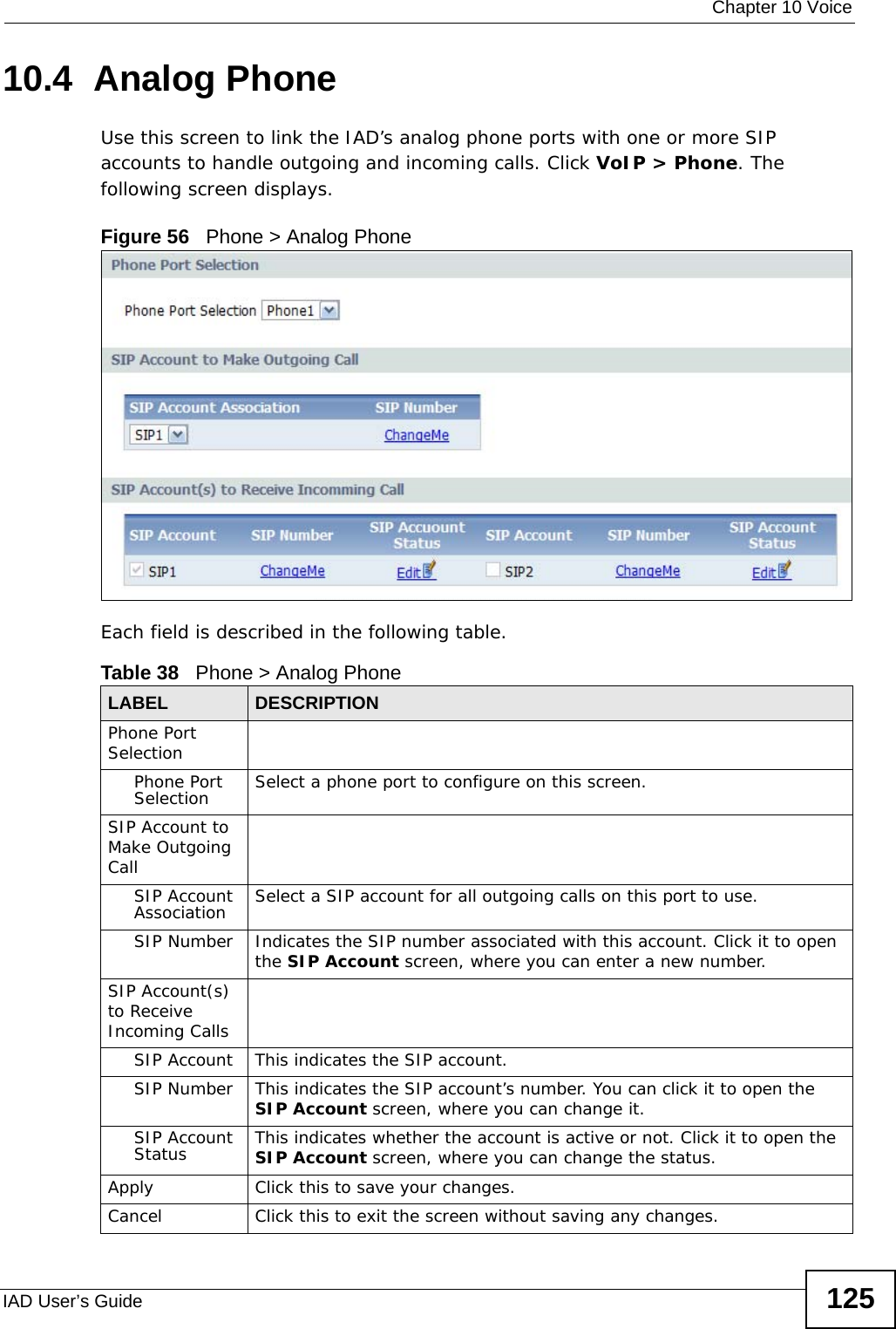
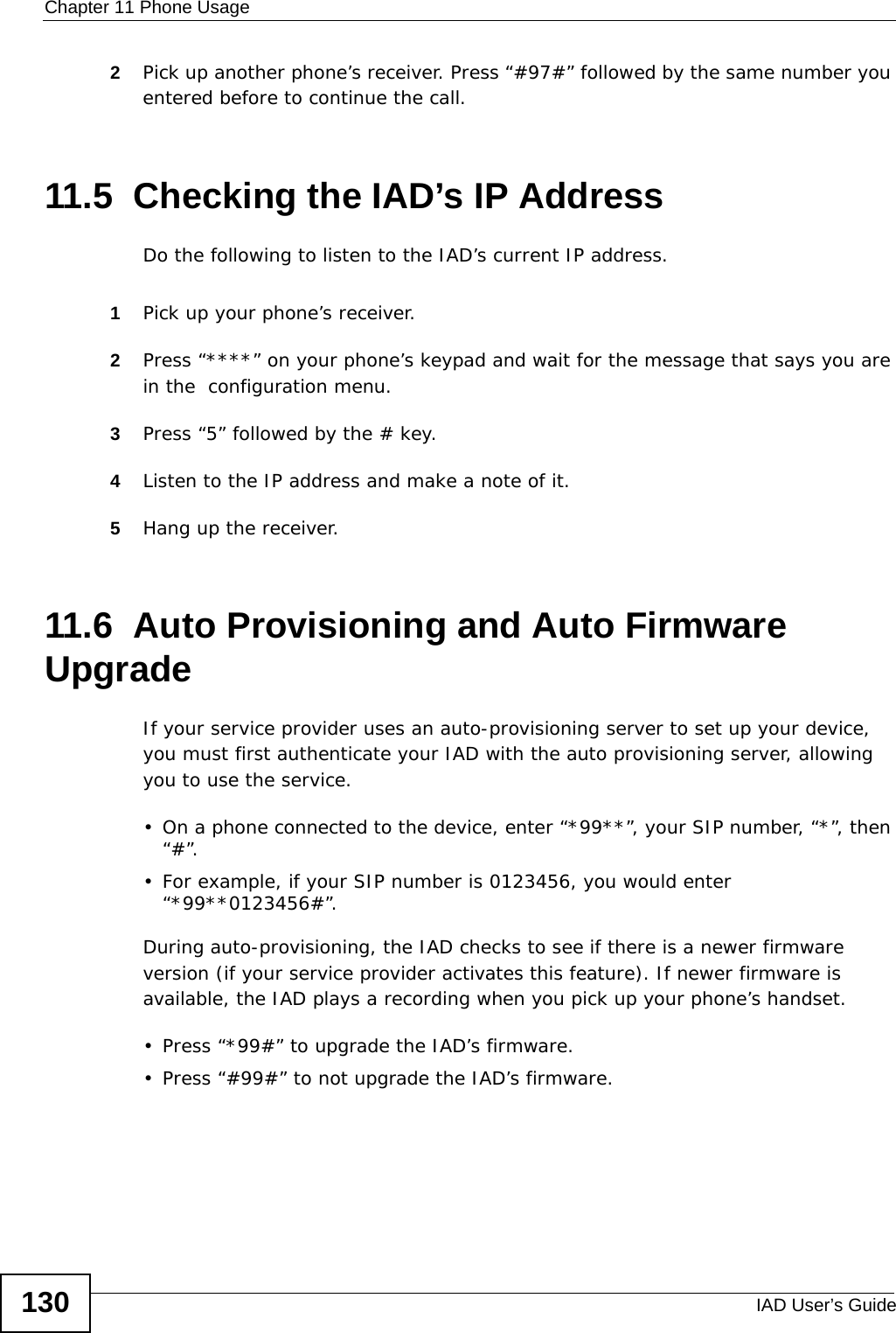
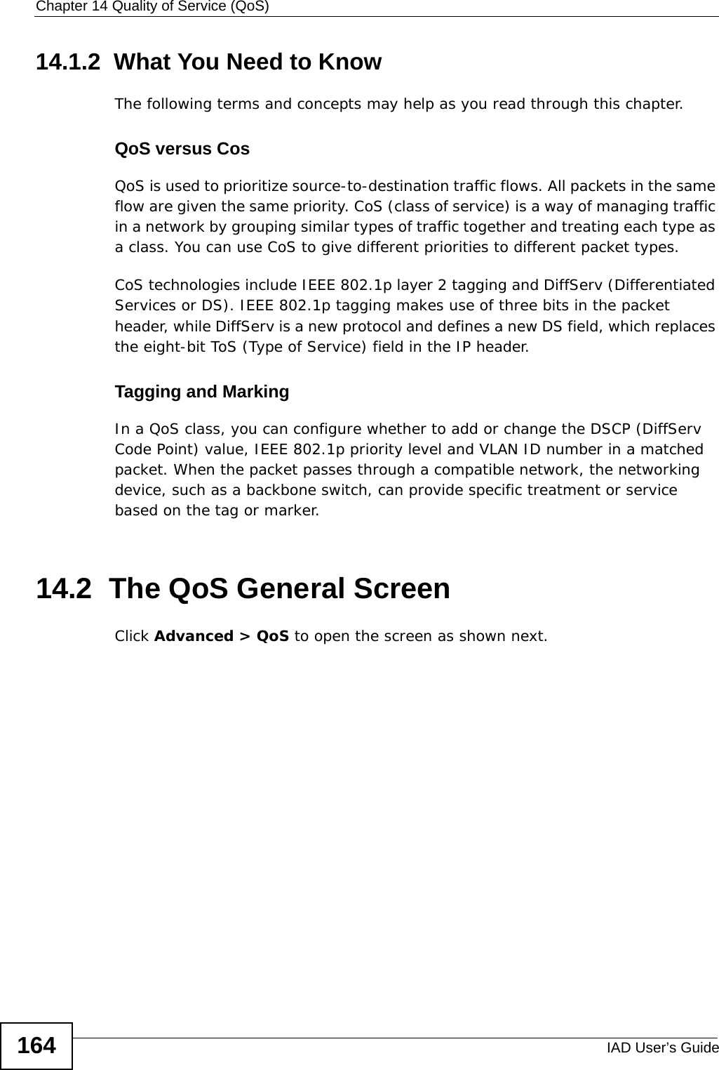
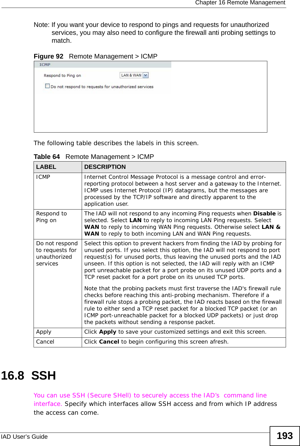
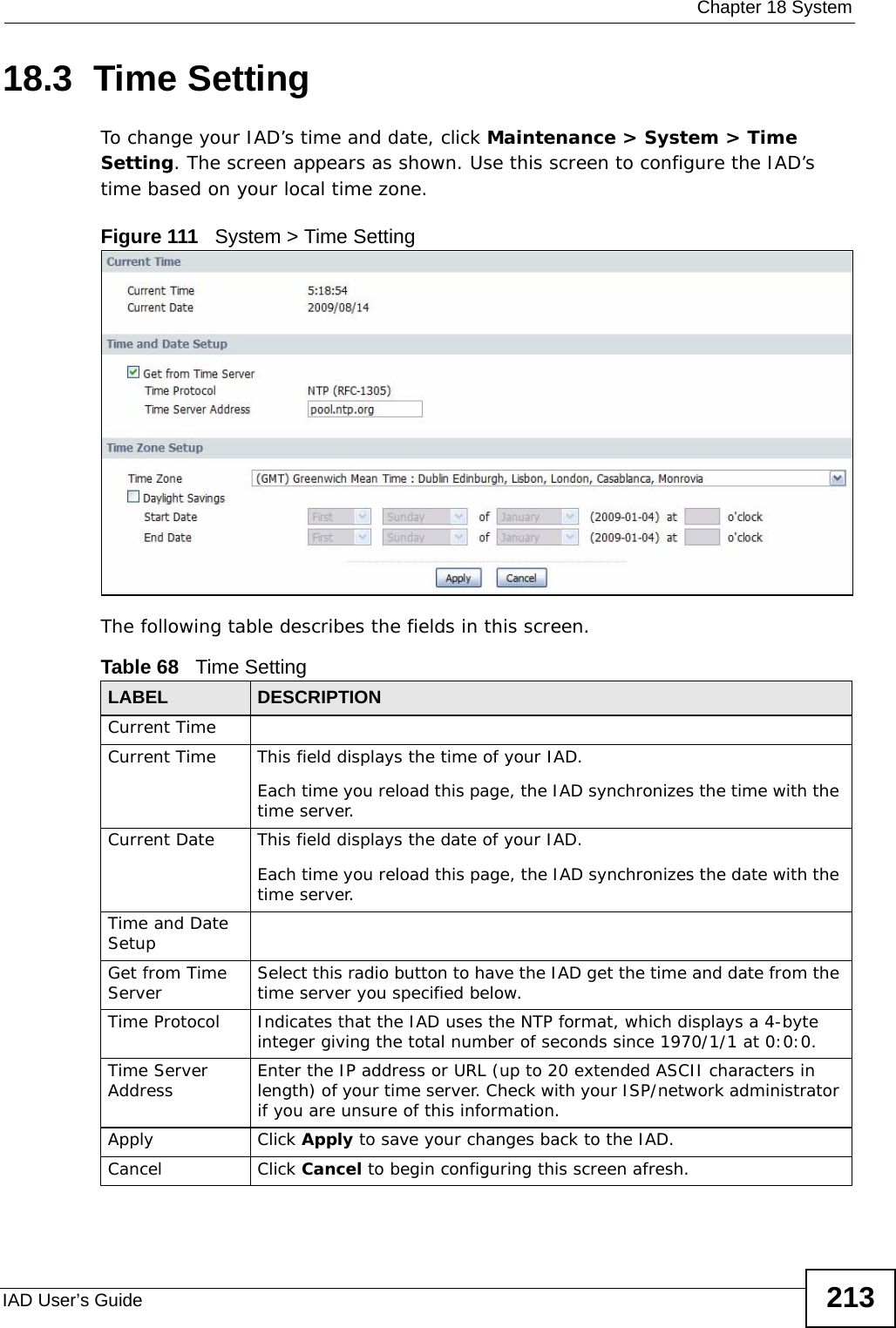
![Appendix B Setting Up Your Computer’s IP AddressIAD User’s Guide 2492In the Command Prompt window, type "ipconfig" and then press [ENTER]. You can also go to Start > Control Panel > Network Connections, right-click a network connection, click Status and then click the Support tab to view your IP address and connection information.Windows VistaThis section shows screens from Windows Vista Professional.1Click Start > Control Panel.Figure 126 Windows Vista: Start Menu2In the Control Panel, click the Network and Internet icon.Figure 127 Windows Vista: Control Panel](https://usermanual.wiki/ZyXEL-Communications/P3202HNBA.Installation-guide-1-of-2/User-Guide-1219892-Page-249.png)