ZyXEL Communications P3202HNBA 802.11N GPON VoIP IAD User Manual ZyBook2
ZyXEL Communications Corporation 802.11N GPON VoIP IAD ZyBook2
UserManual.wiki
>
ZyXEL Communications
>
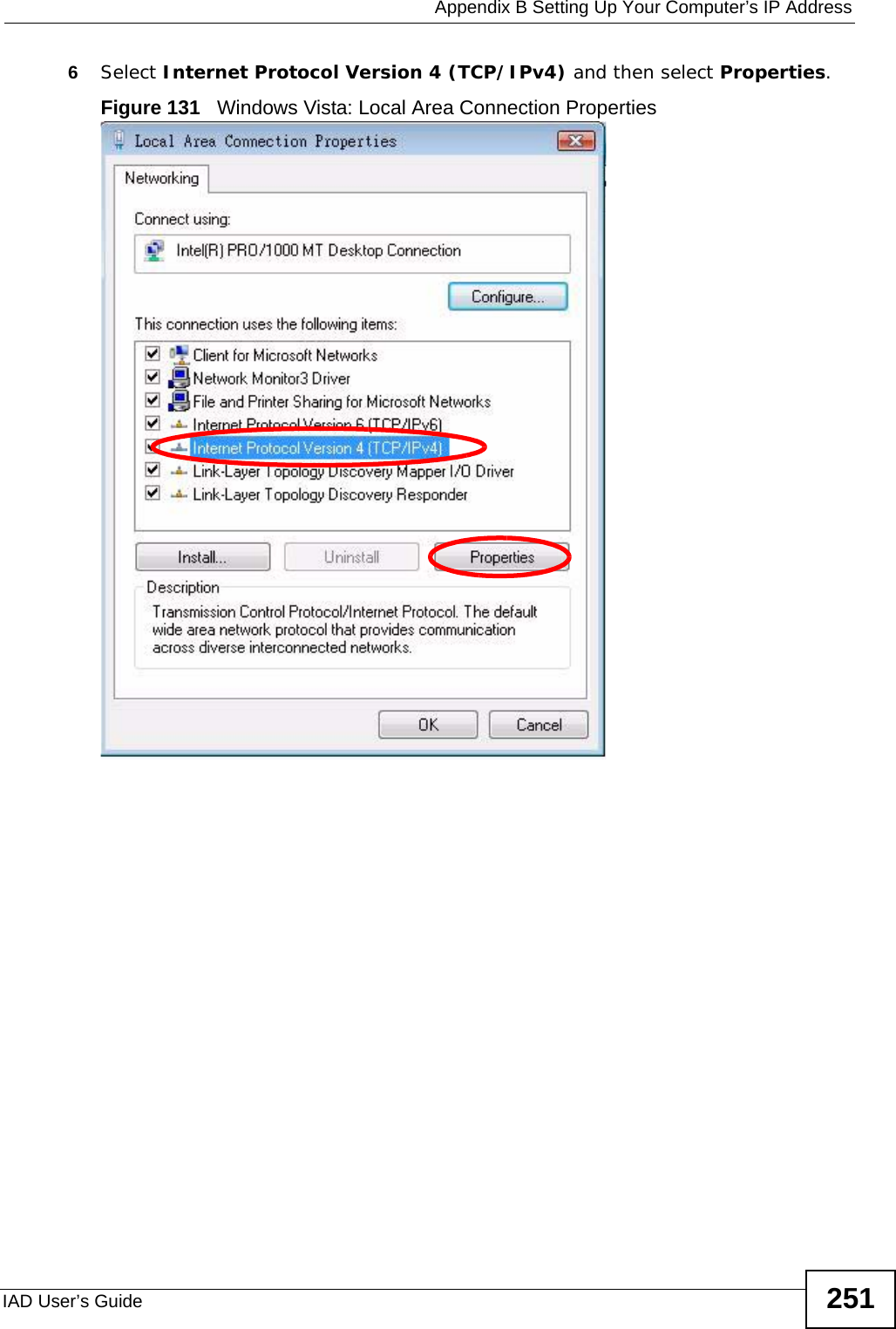
P3202HNBA User Manual
>
Installation guide 2 of 2
Contents
1.
Installation guide 1 of 2
2.
Installation guide 2 of 2
Installation guide 2 of 2
Navigation menu
Upload a User Manual
Namespaces
Wiki Guide
HTML
PDF
Info
Views
User Manual
Discussion / Help
Navigation
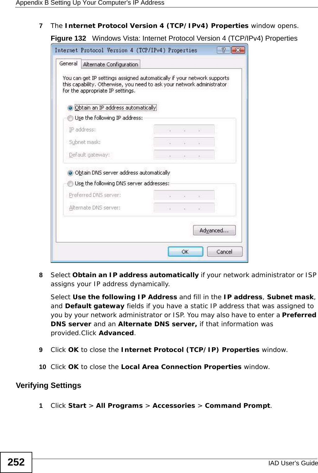
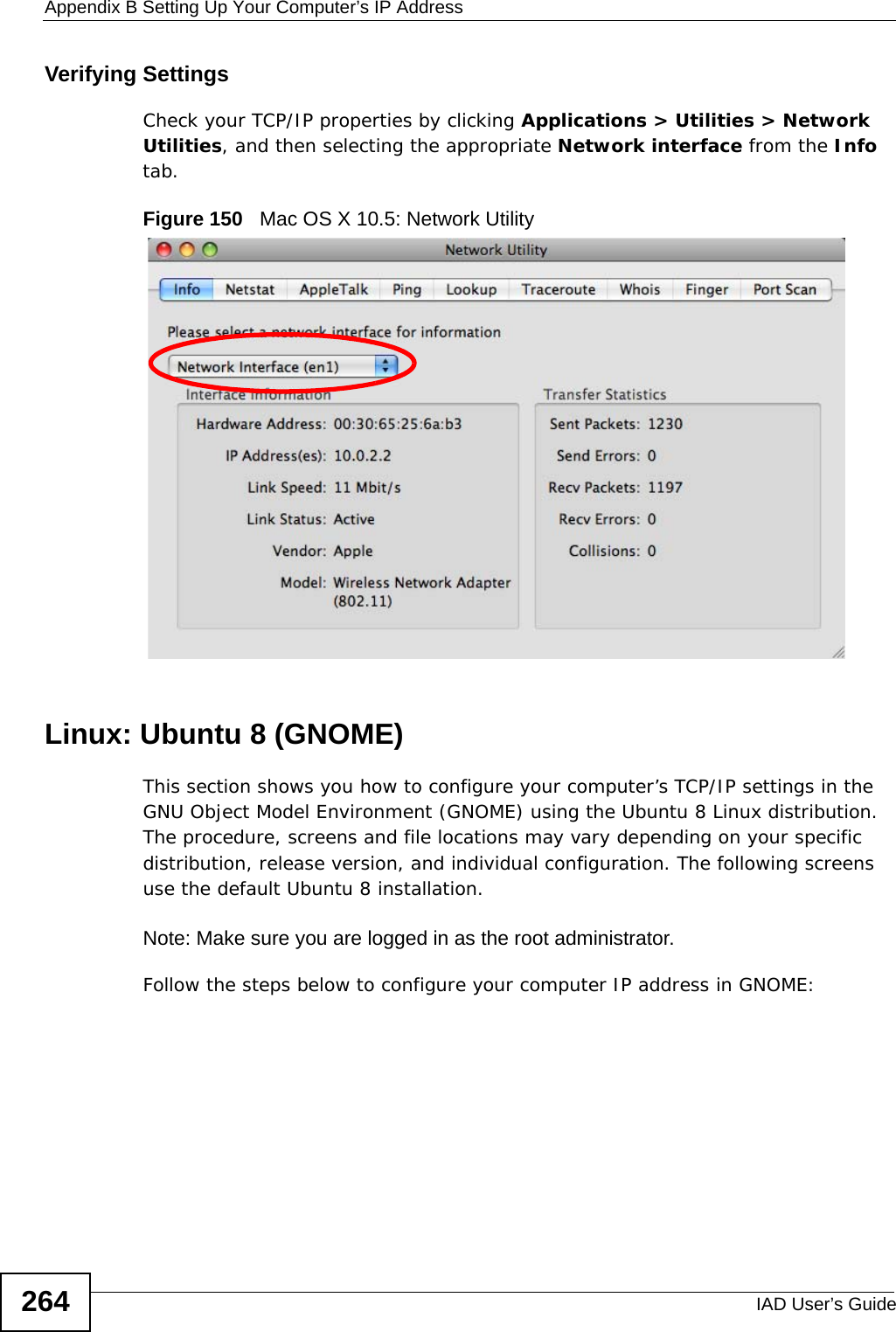
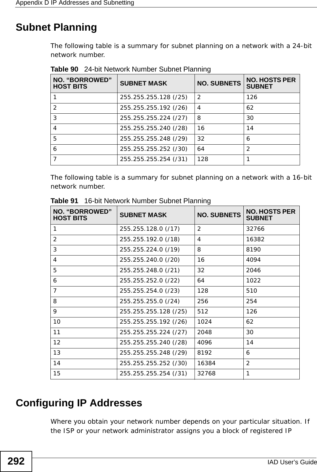
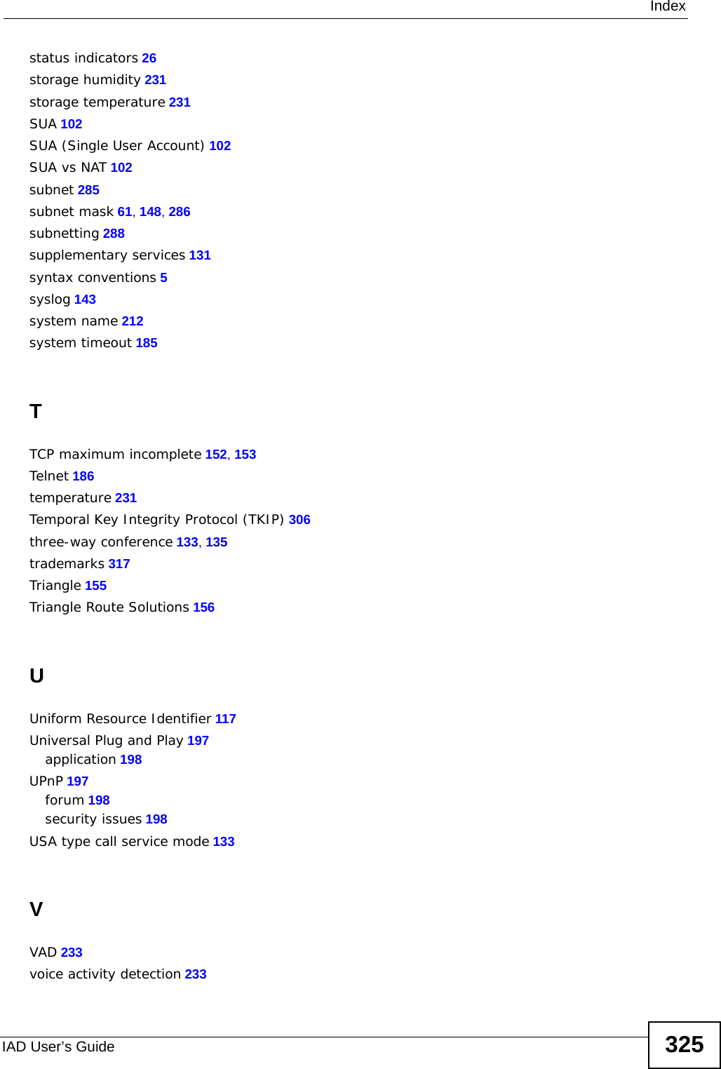
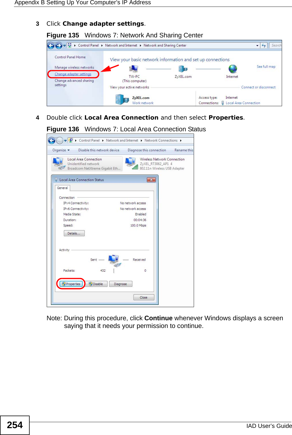
![Appendix B Setting Up Your Computer’s IP AddressIAD User’s Guide 2532In the Command Prompt window, type "ipconfig" and then press [ENTER]. You can also go to Start > Control Panel > Network Connections, right-click a network connection, click Status and then click the Support tab to view your IP address and connection information.Windows 7This section shows screens from Windows 7 Enterprise.1Click Start > Control Panel.Figure 133 Windows 7: Start Menu2In the Control Panel, click View network status and tasks under the Network and Internet category.Figure 134 Windows 7: Control Panel](https://usermanual.wiki/ZyXEL-Communications/P3202HNBA.Installation-guide-2-of-2/User-Guide-1219893-Page-3.png)
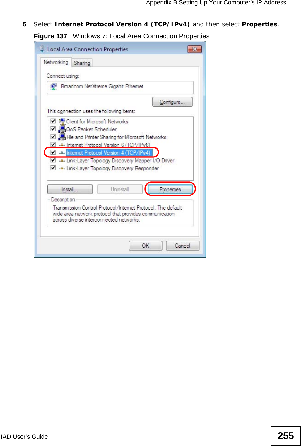
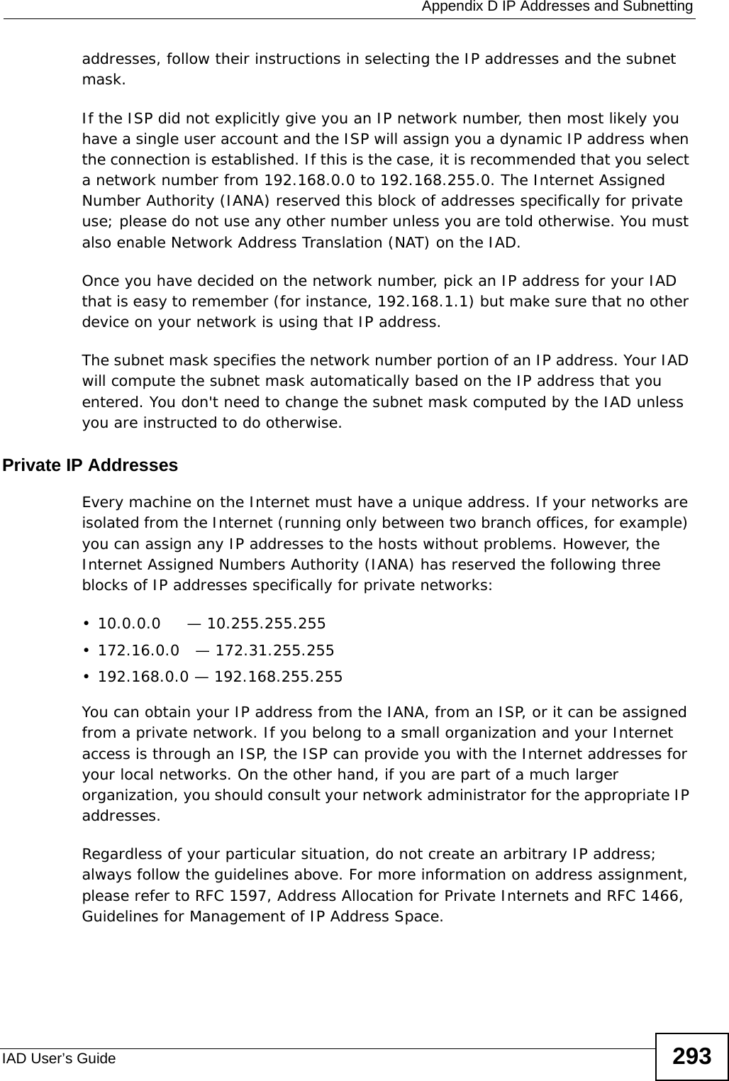
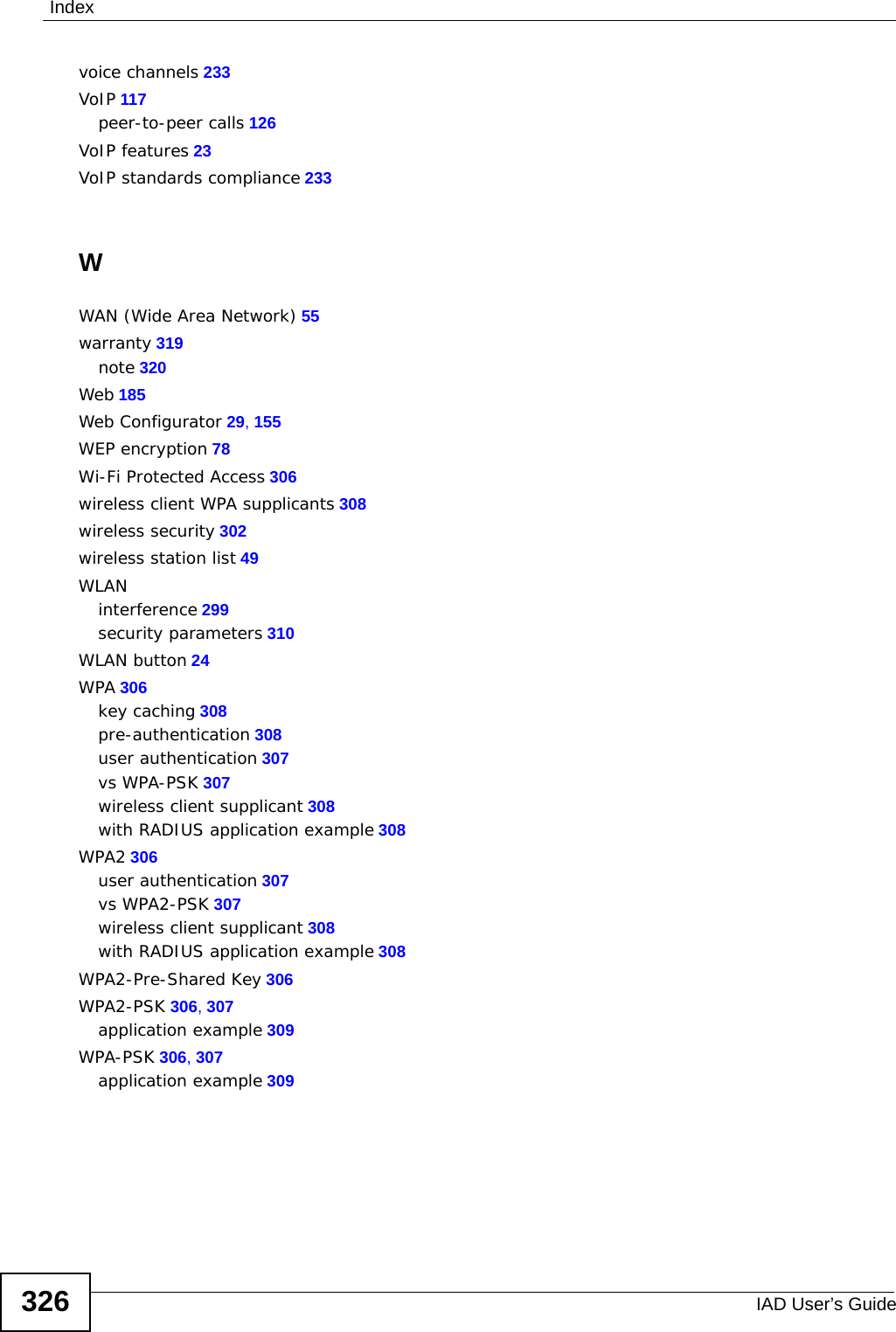
![Appendix B Setting Up Your Computer’s IP AddressIAD User’s Guide2566The Internet Protocol Version 4 (TCP/IPv4) Properties window opens.Figure 138 Windows 7: Internet Protocol Version 4 (TCP/IPv4) Properties7Select Obtain an IP address automatically if your network administrator or ISP assigns your IP address dynamically.Select Use the following IP Address and fill in the IP address, Subnet mask, and Default gateway fields if you have a static IP address that was assigned to you by your network administrator or ISP. You may also have to enter a Preferred DNS server and an Alternate DNS server, if that information was provided. Click Advanced if you want to configure advanced settings for IP, DNS and WINS. 8Click OK to close the Internet Protocol (TCP/IP) Properties window.9Click OK to close the Local Area Connection Properties window.Verifying Settings1Click Start > All Programs > Accessories > Command Prompt.2In the Command Prompt window, type "ipconfig" and then press [ENTER].](https://usermanual.wiki/ZyXEL-Communications/P3202HNBA.Installation-guide-2-of-2/User-Guide-1219893-Page-6.png)