ZyXEL Communications P330W 802.11g Wireless Broadband Router User Manual WR254MNL 1
ZyXEL Communications Corporation 802.11g Wireless Broadband Router WR254MNL 1
UserManual.wiki
>
ZyXEL Communications
>
P330W User Manual
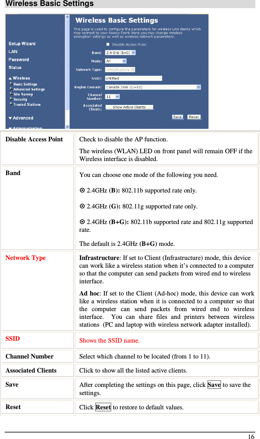
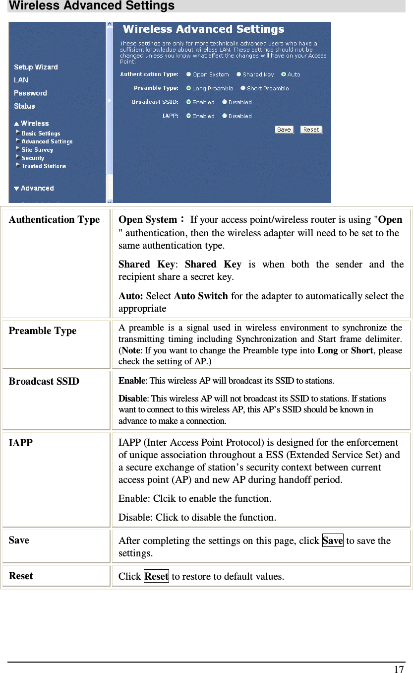
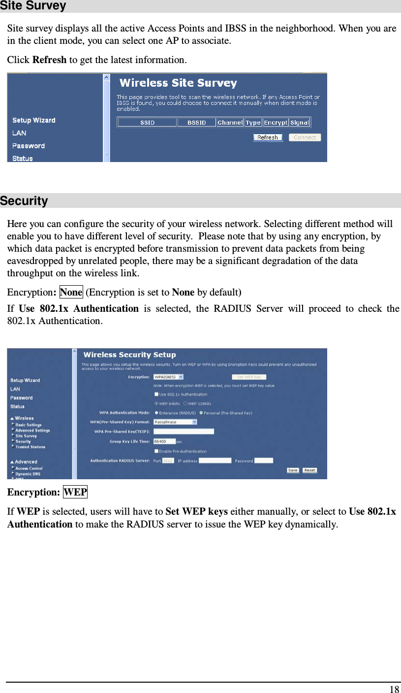
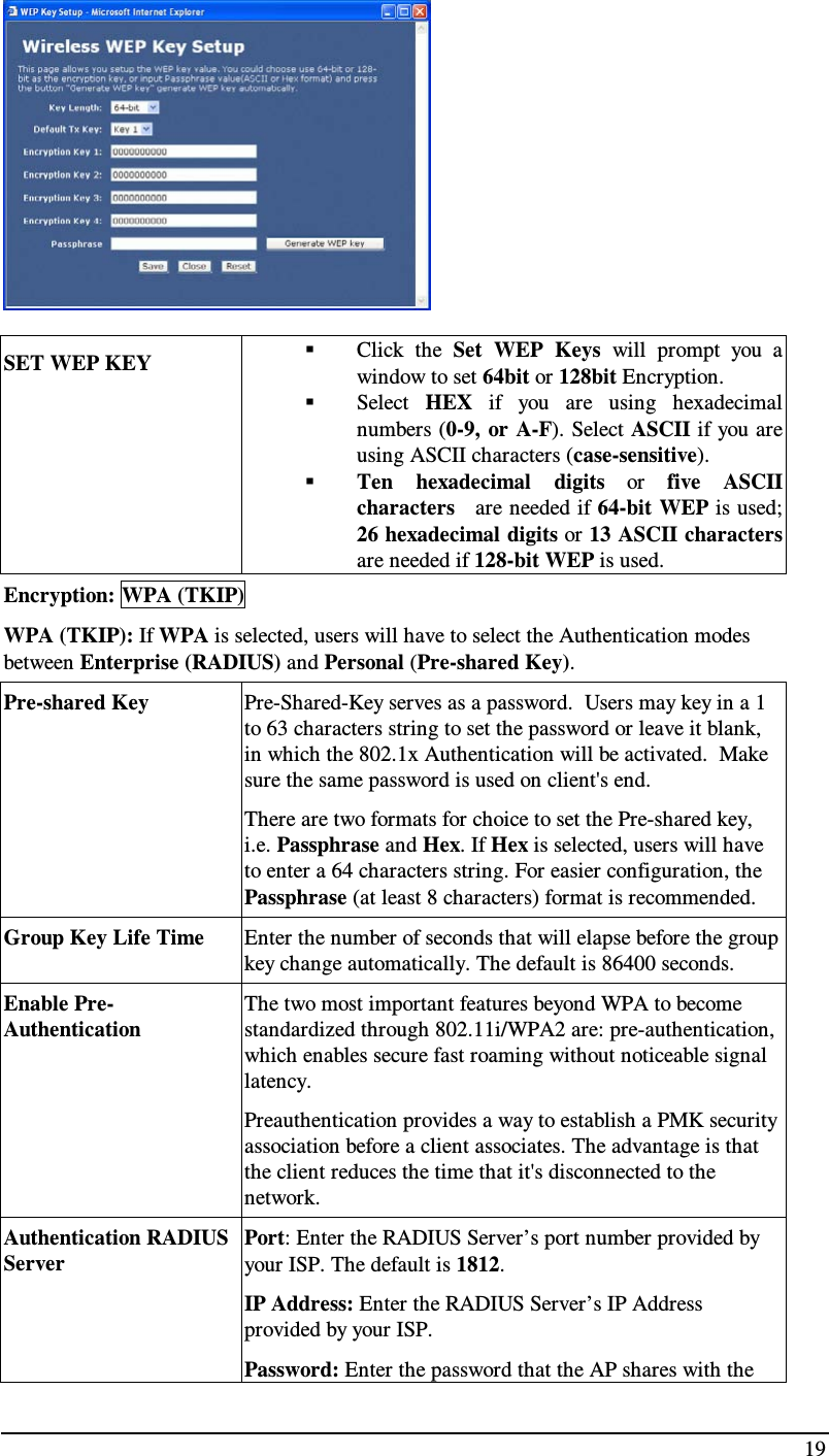
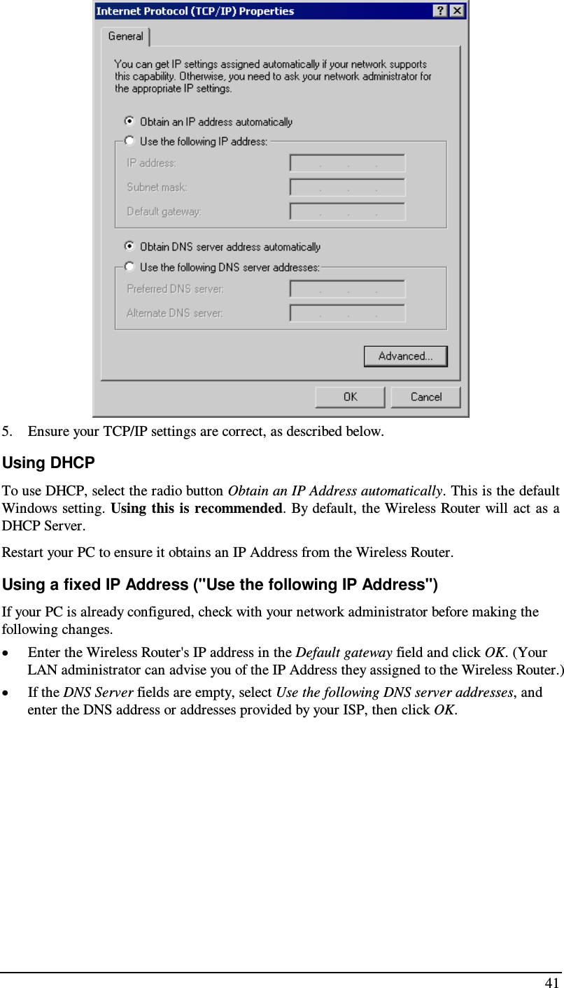
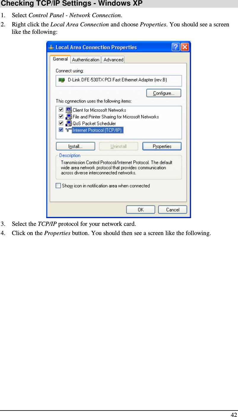
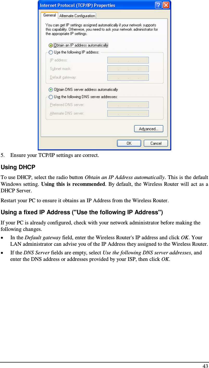
User Manual
Navigation menu
Upload a User Manual
Namespaces
Wiki Guide
HTML
PDF
Info
Views
User Manual
Discussion / Help
Navigation