ZyXEL Communications P660HNT1 802.11n Wireless ADSL2+ 4-port Gateway User Manual
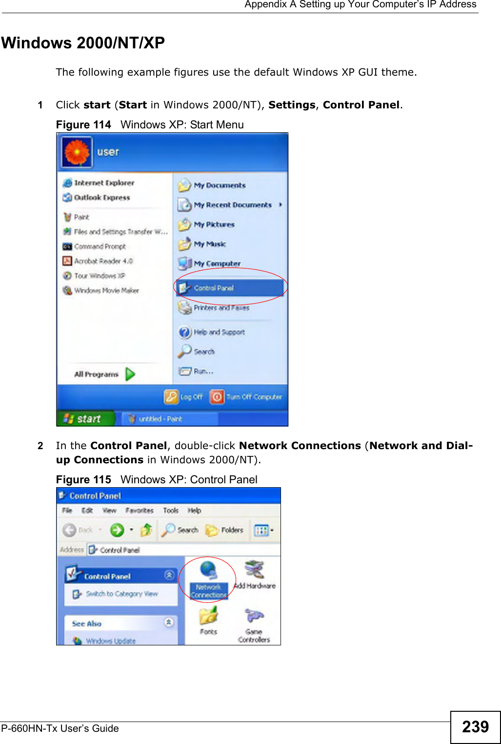
ZyXEL Communications Corporation 802.11n Wireless ADSL2+ 4-port Gateway
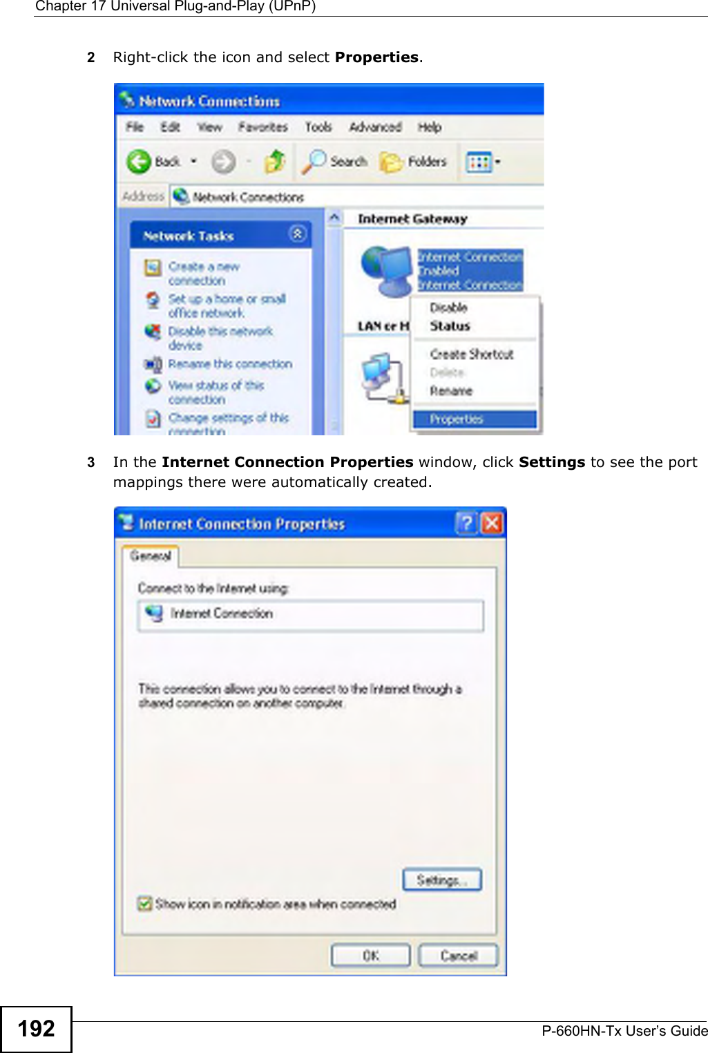
UserManual.wiki
>
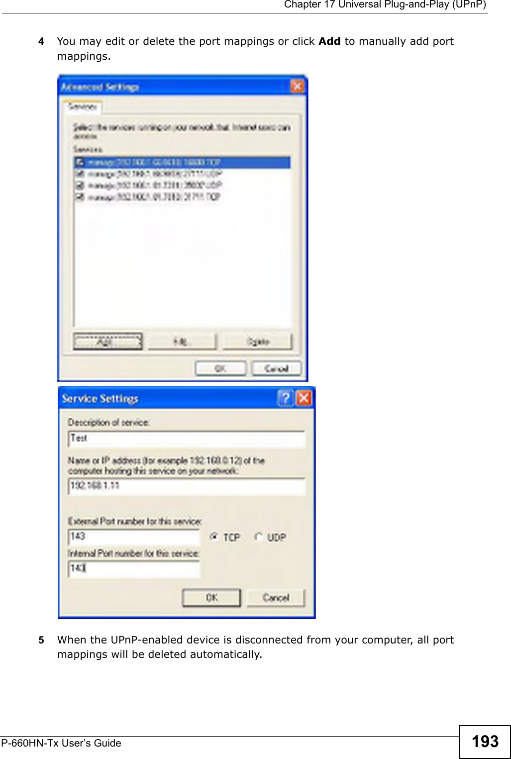
ZyXEL Communications
>
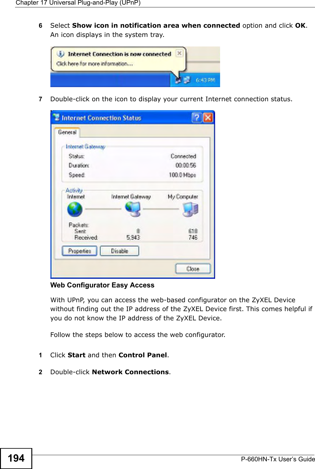
P660HNT1 User Manual
>
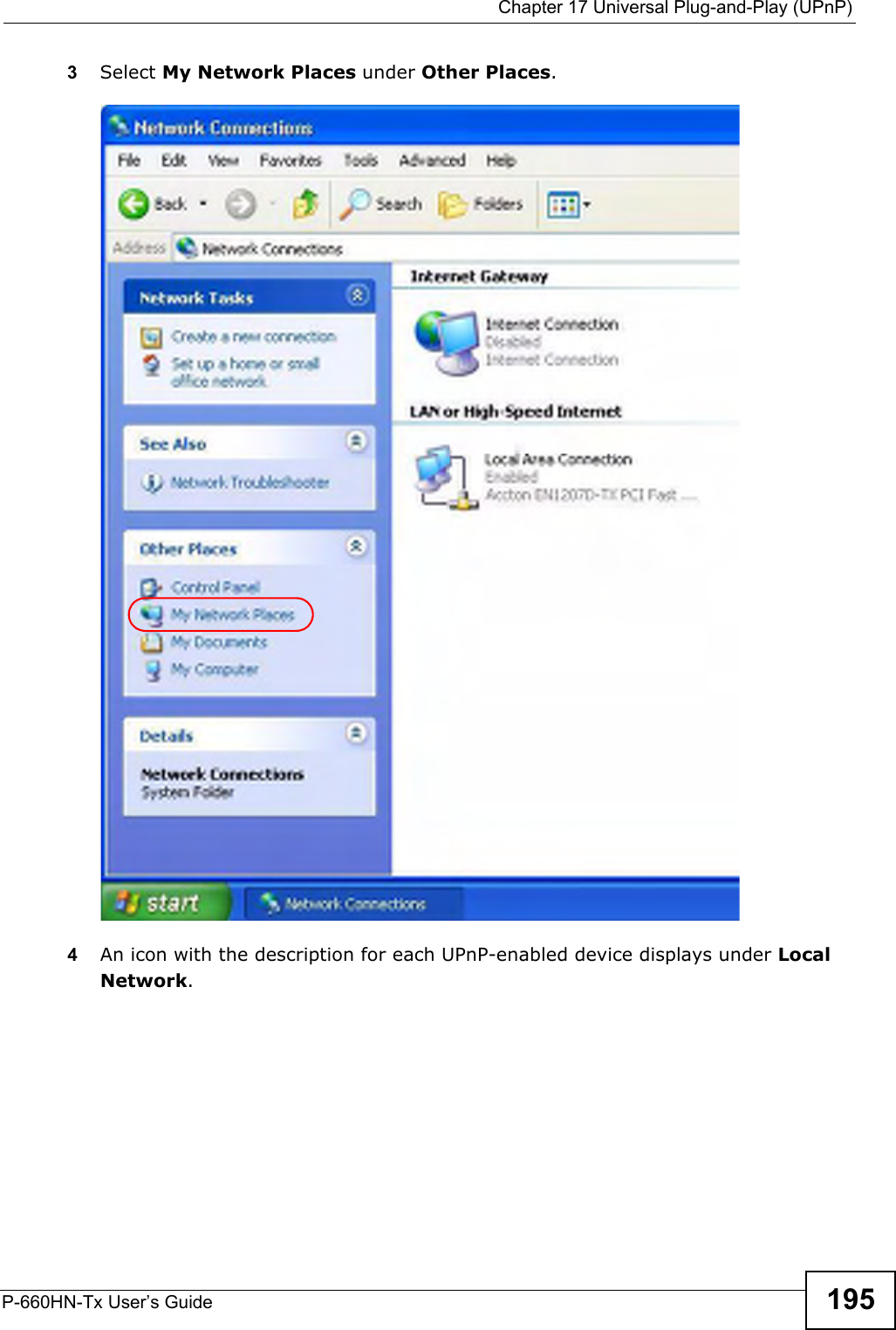
User Manual-2
Contents
1.
Users Manual-1
2.
User Manual-2
User Manual-2
Navigation menu
Upload a User Manual
Namespaces
Wiki Guide
HTML
PDF
Info
Views
User Manual
Discussion / Help
Navigation


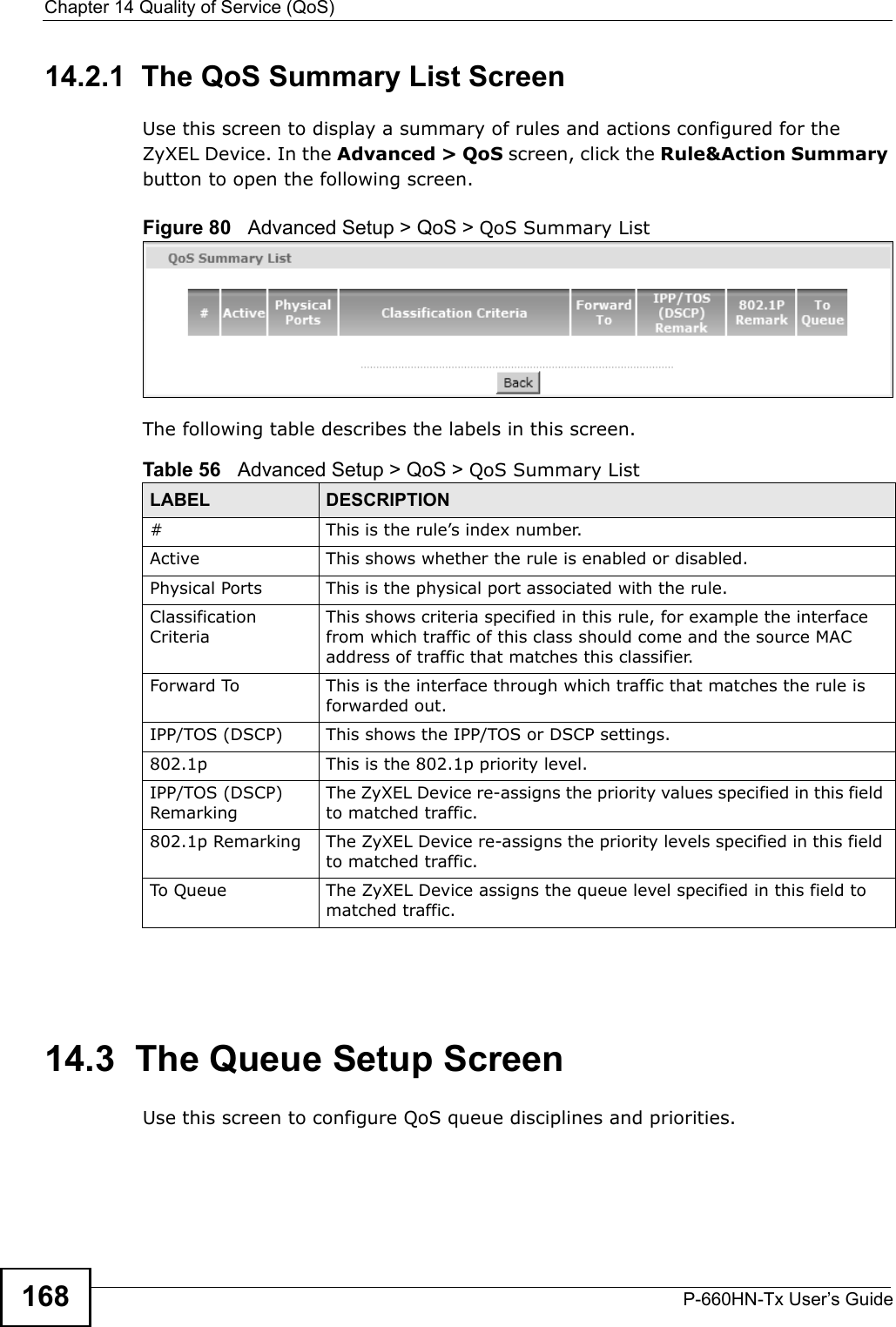
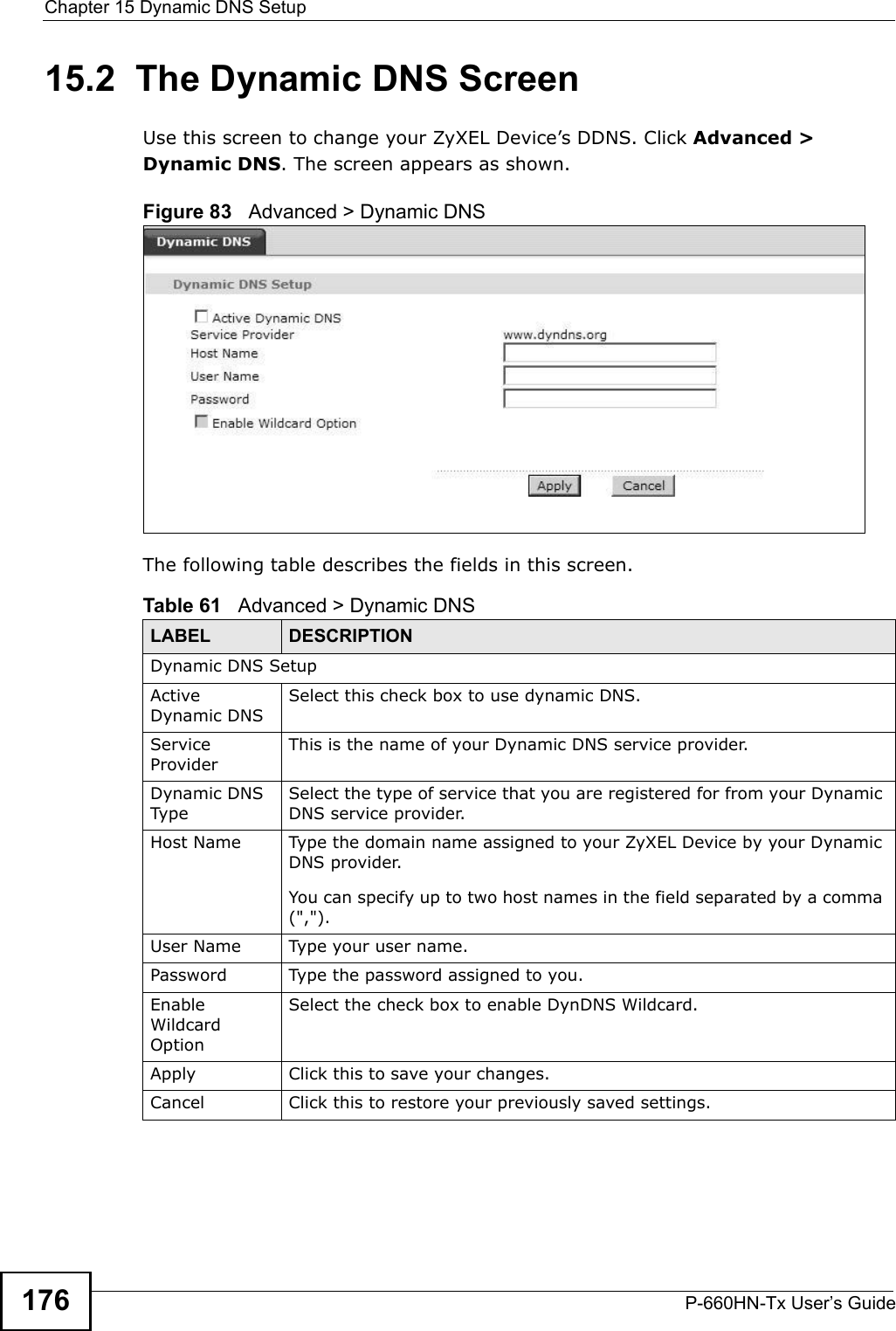
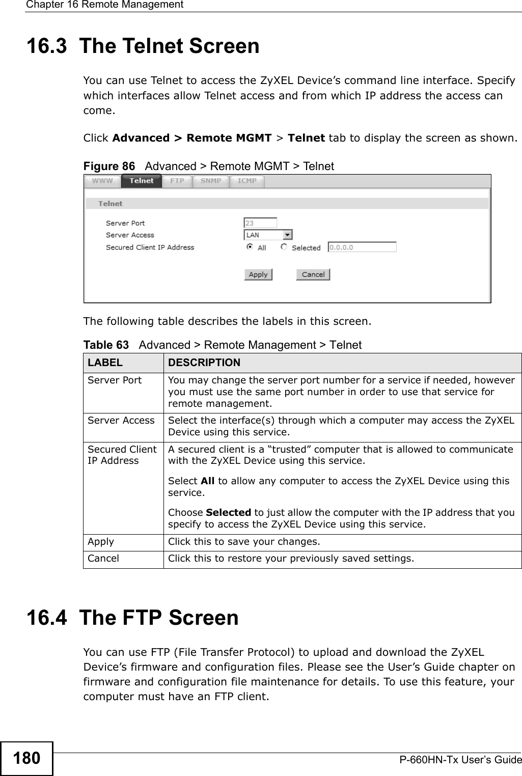
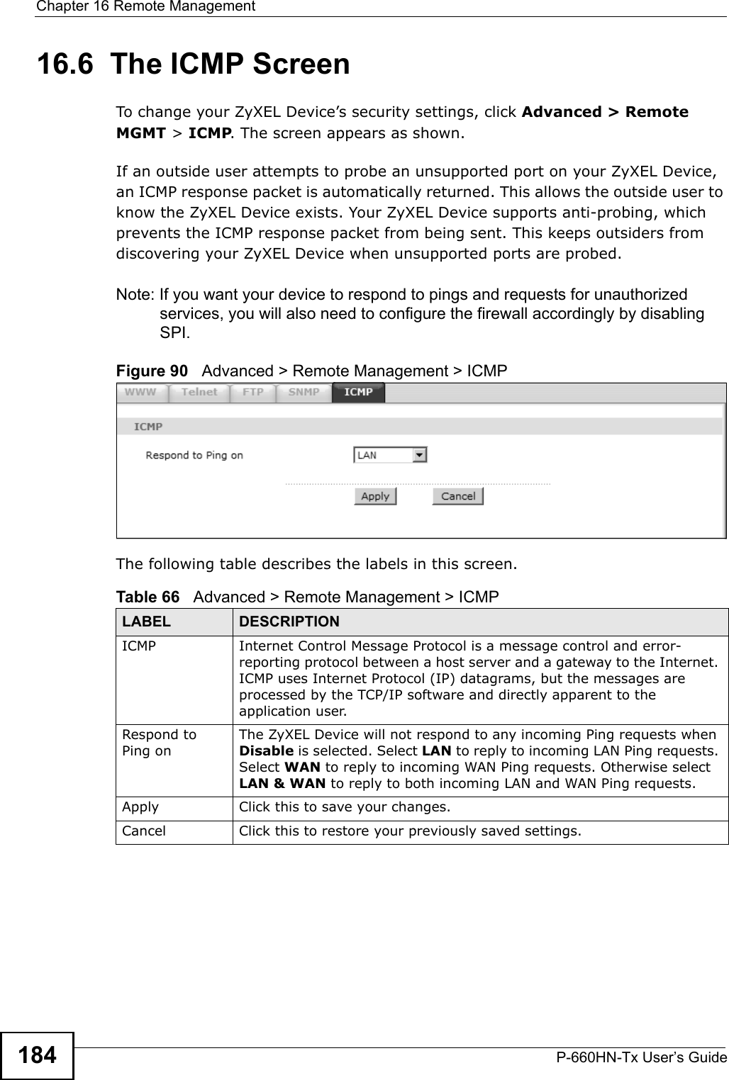


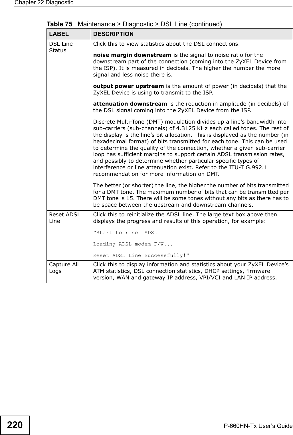
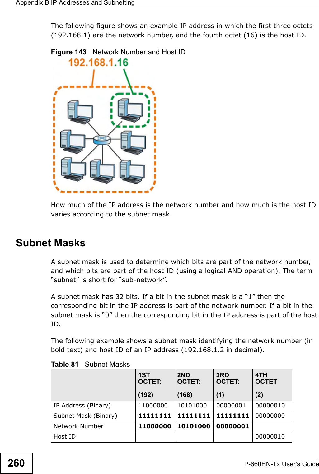
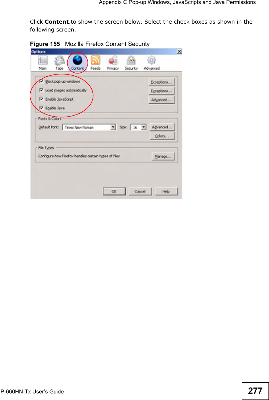
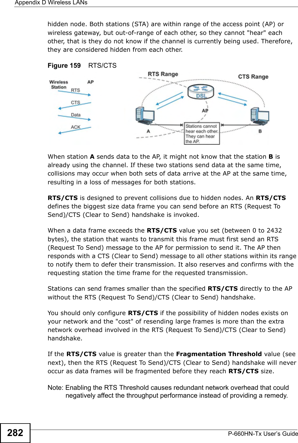
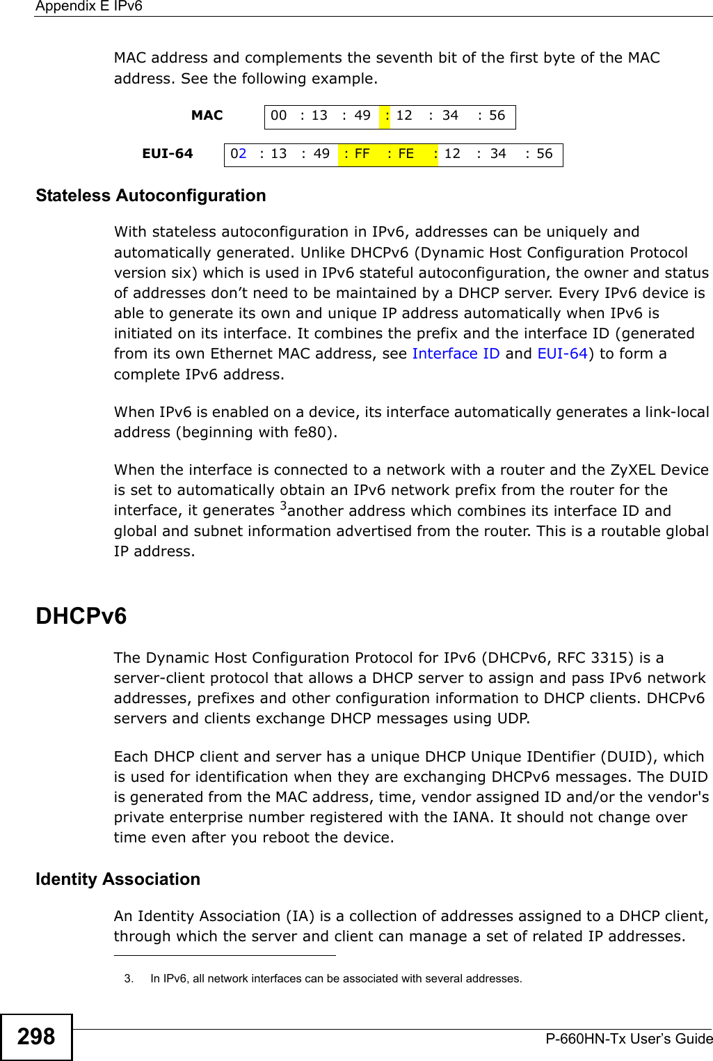
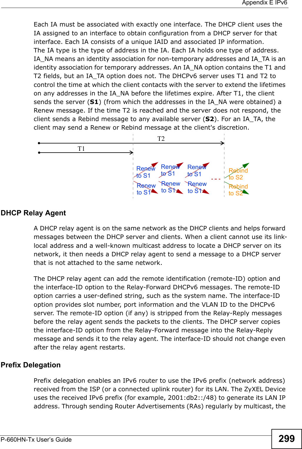
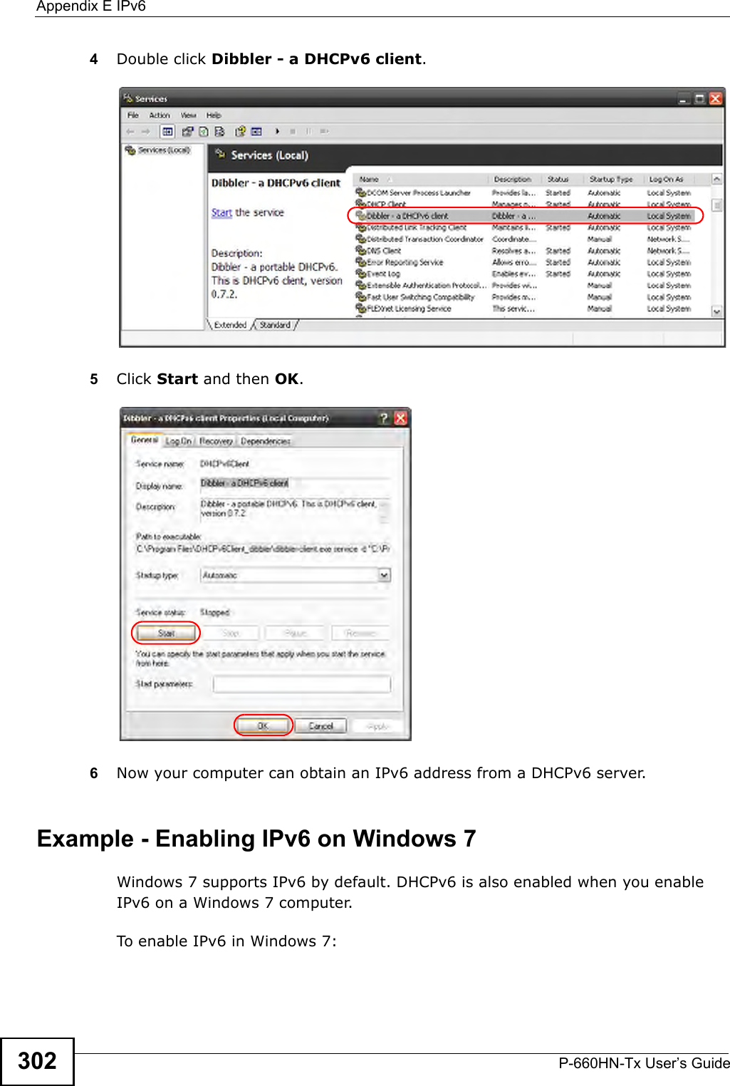
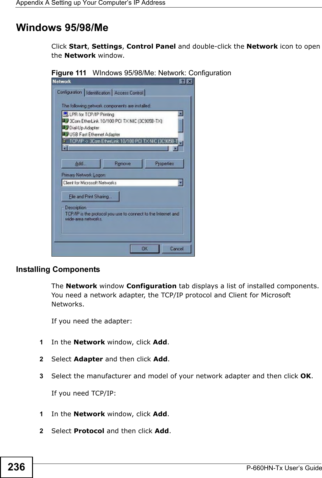
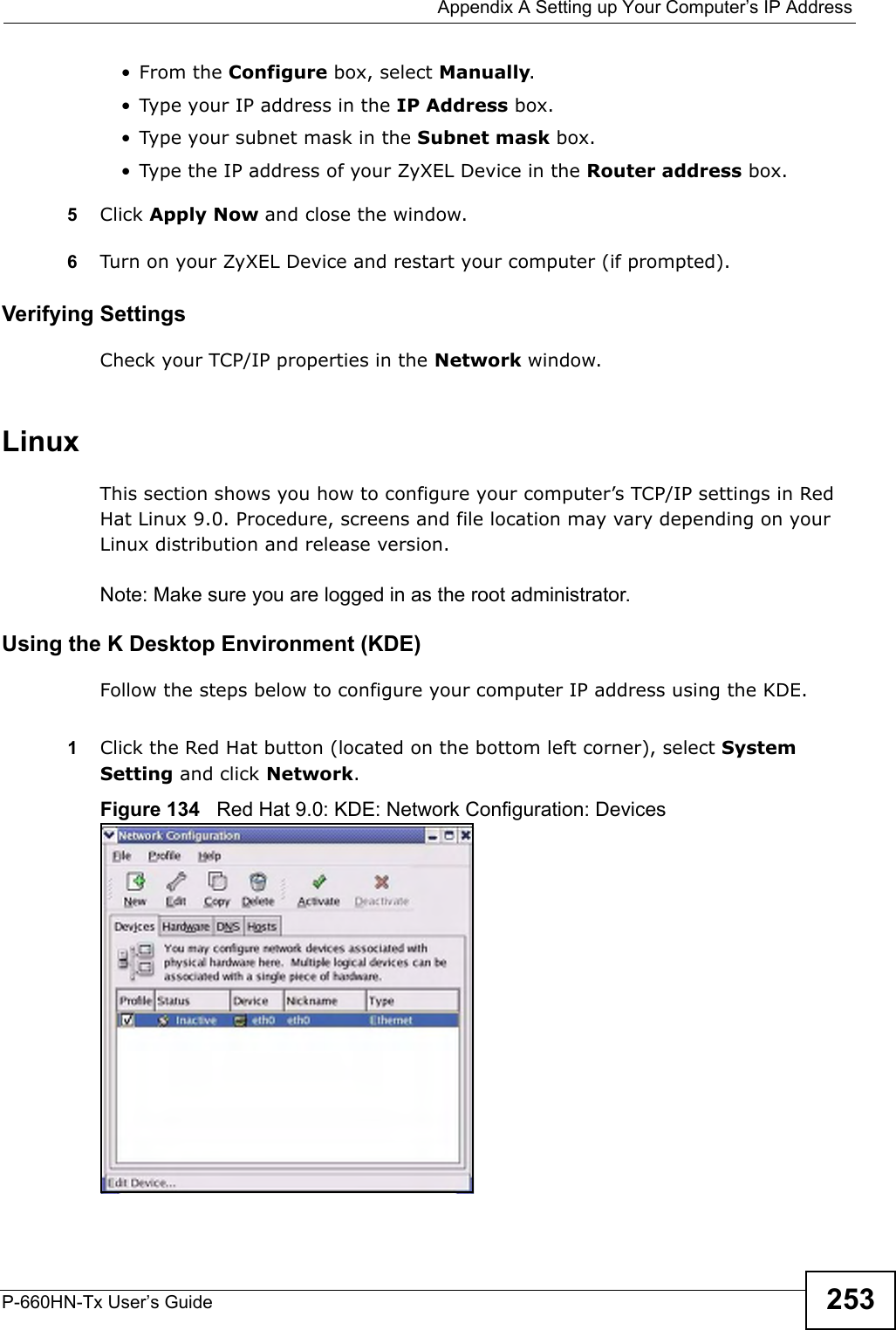
![Chapter 23 TroubleshootingP-660HN-Tx User’s Guide 223•The default IP address is 192.168.1.1.•If you changed the IP address (Section 7.2 on page 91), use the new IP address.• If you changed the IP address and have forgotten it, see the troubleshooting suggestions for I forgot the IP address for the ZyXEL Device.2Check the hardware connections, and make sure the LEDs are behaving as expected. See the Quick Start Guide.3Make sure your Internet browser does not block pop-up windows and has JavaScripts and Java enabled. See Appendix C on page 269.4Reset the device to its factory defaults, and try to access the ZyXEL Device with the default IP address. See Section 1.7 on page 27.5If the problem continues, contact the network administrator or vendor, or try one of the advanced suggestions.Advanced Suggestions• Try to access the ZyXEL Device using another service, such as Telnet. If you can access the ZyXEL Device, check the remote management settings and firewall rules to find out why the ZyXEL Device does not respond to HTTP. • If your computer is connected to the WAN port or is connected wirelessly, use a computer that is connected to a ETHERNET port.I can see the Login screen, but I cannot log in to the ZyXEL Device.1Make sure you have entered the password correctly. The default user and default admin password can be found on the cover page of this User’s Guide. The field is case-sensitive, so make sure [Caps Lock] is not on. 2You cannot log in to the web configurator while someone is using Telnet to access the ZyXEL Device. Log out of the ZyXEL Device in the other session, or ask the person who is logged in to log out. 3Turn the ZyXEL Device off and on. 4If this does not work, you have to reset the device to its factory defaults. See Section 23.1 on page 221.I cannot Telnet to the ZyXEL Device.](https://usermanual.wiki/ZyXEL-Communications/P660HNT1.User-Manual-2/User-Guide-1442527-Page-73.png)
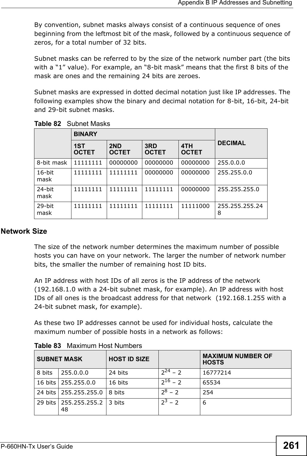
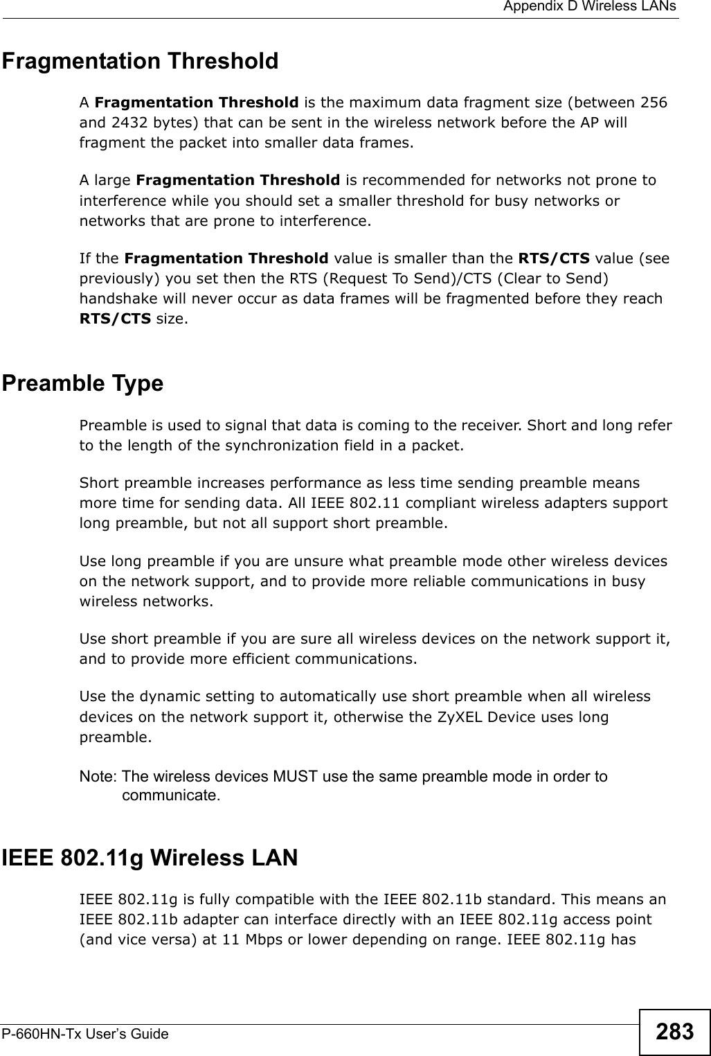
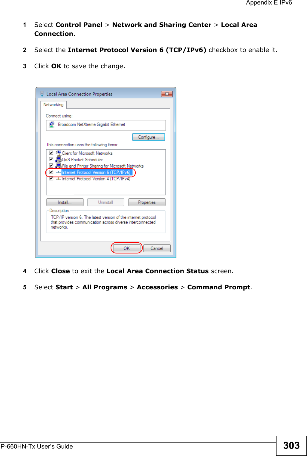
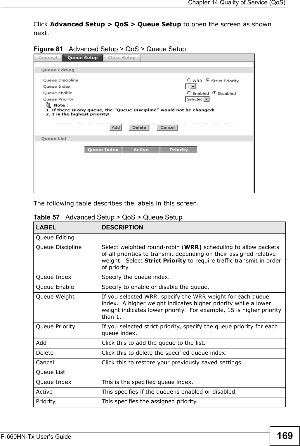
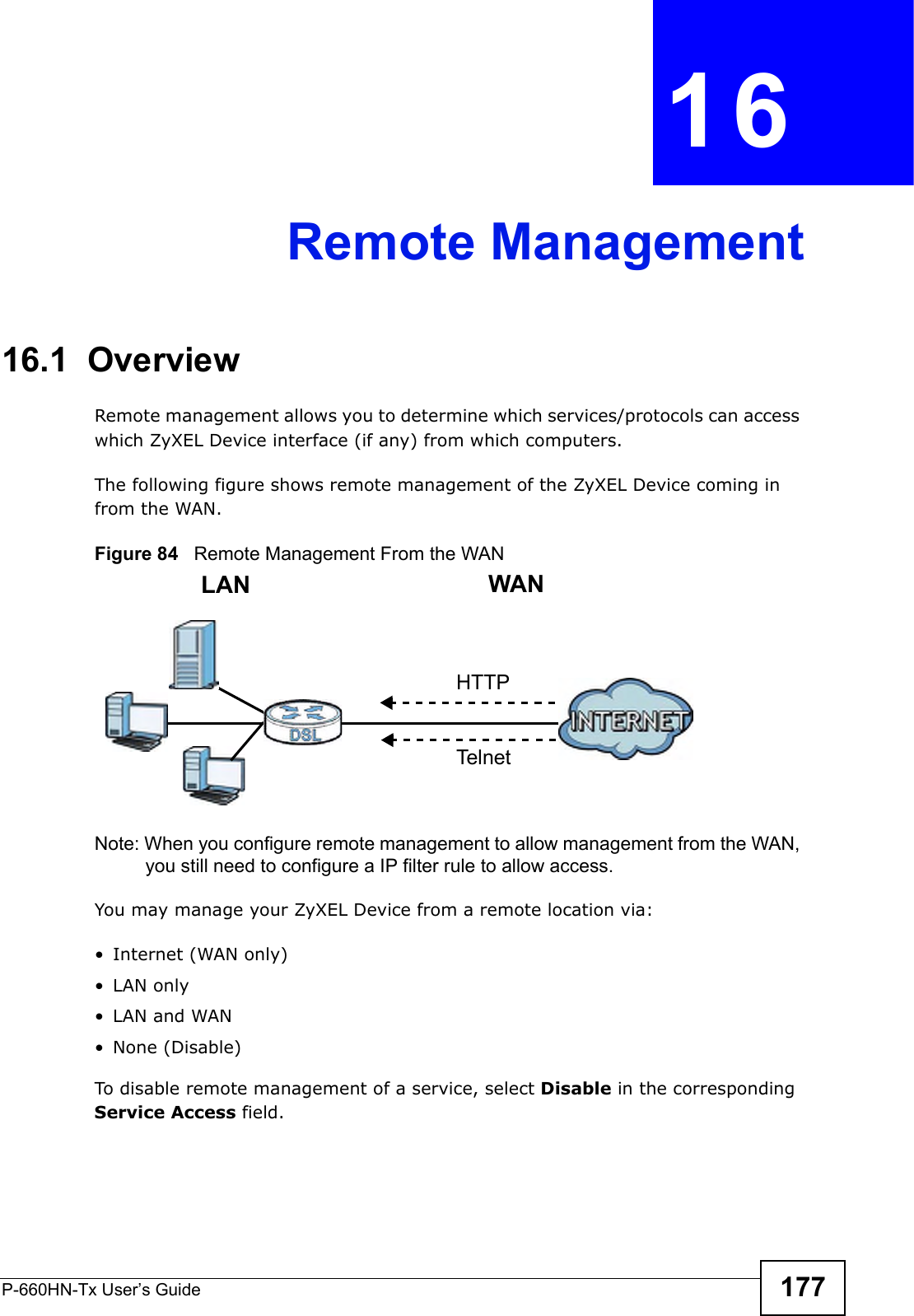
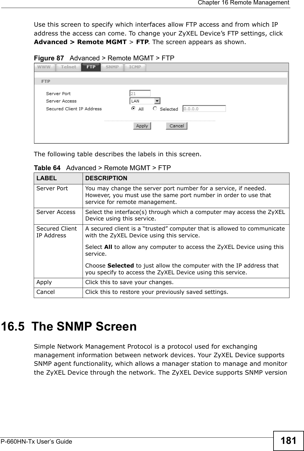
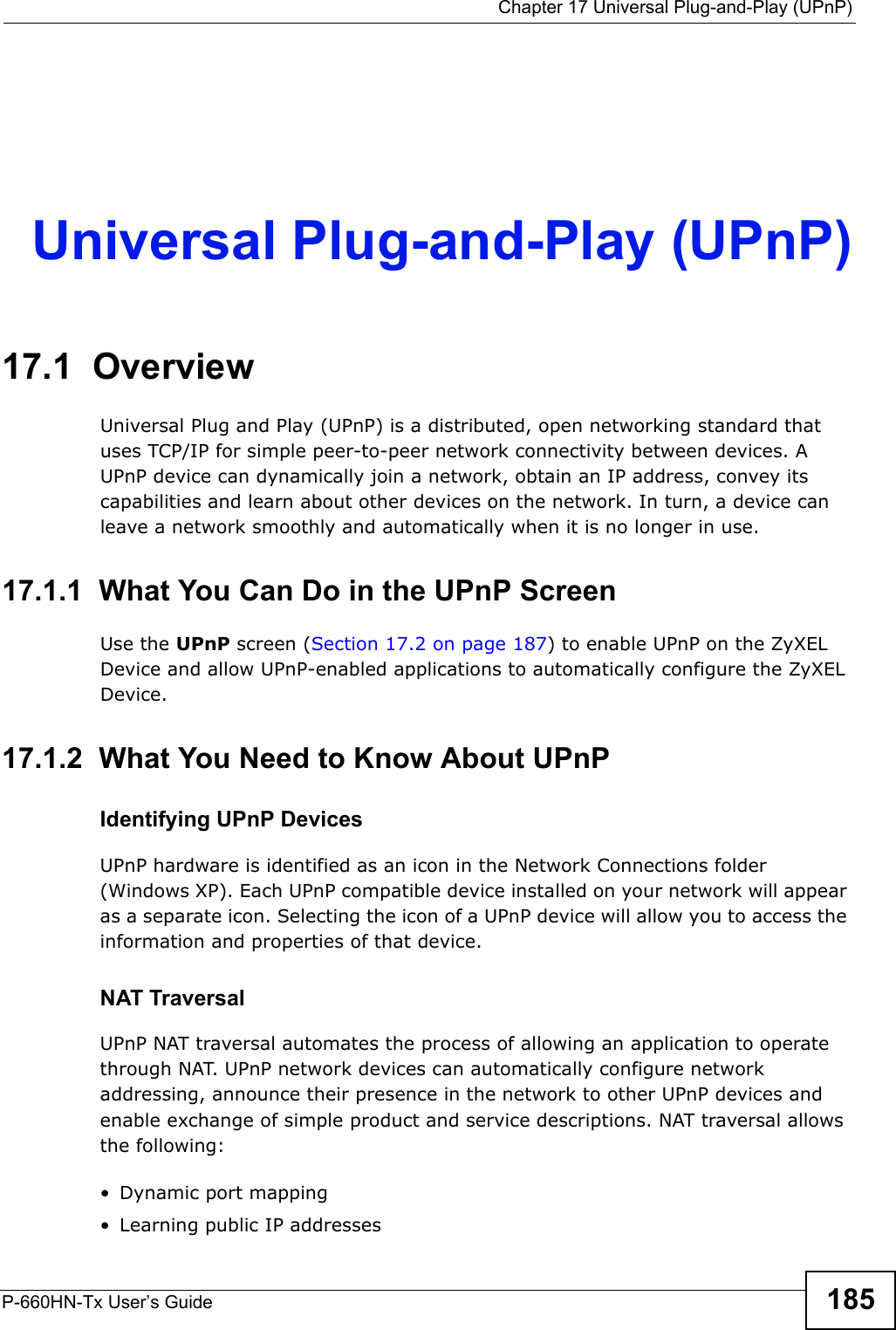
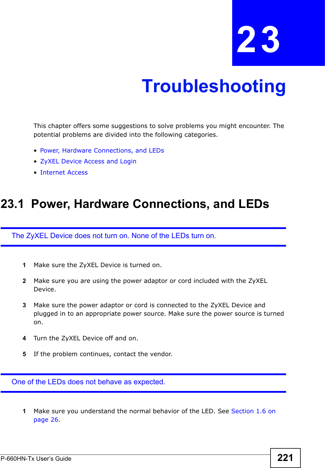
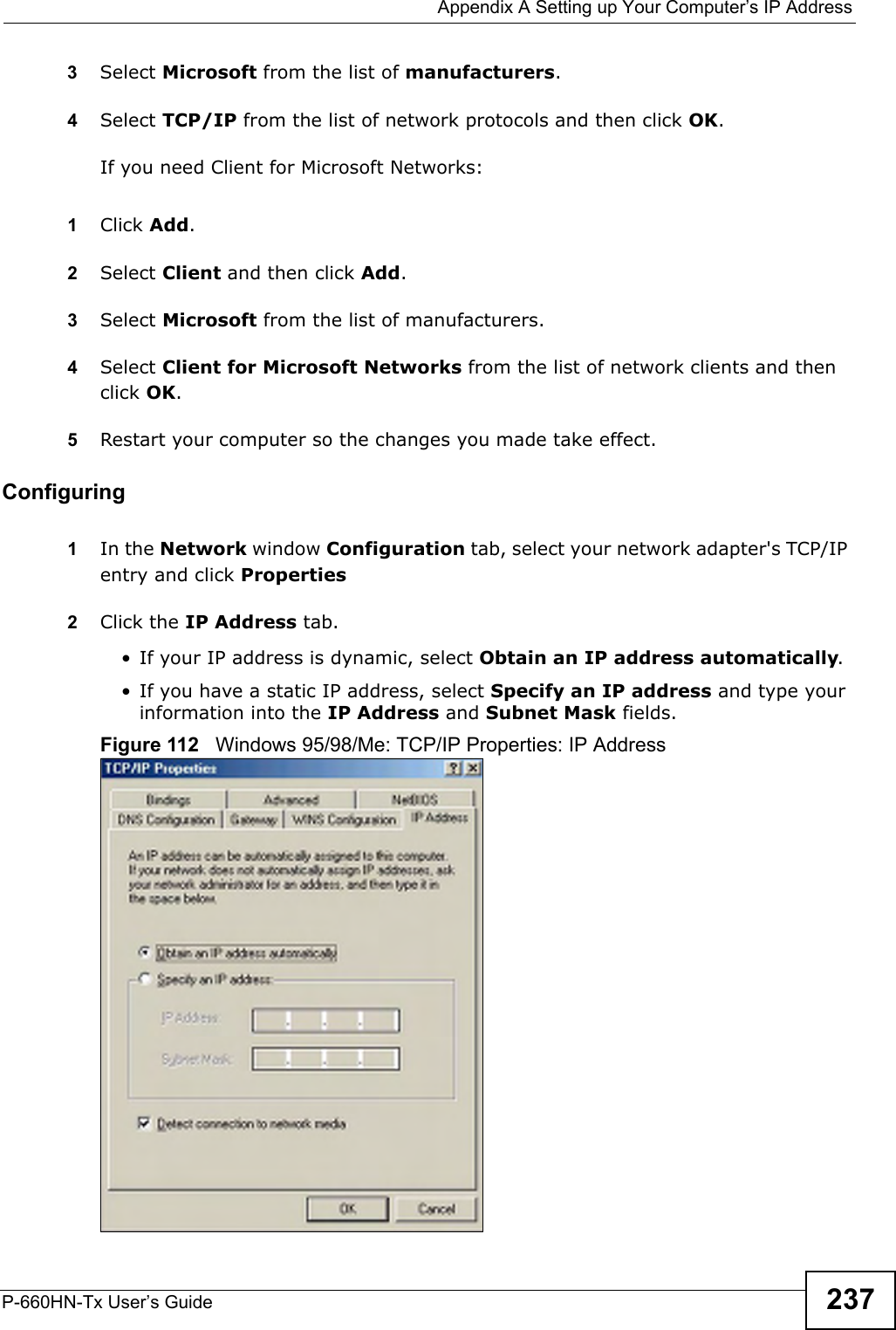
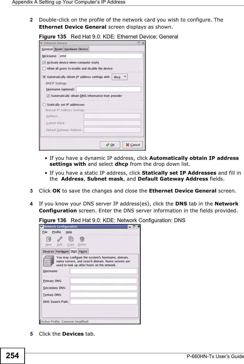
![Chapter 23 TroubleshootingP-660HN-Tx User’s Guide224See the troubleshooting suggestions for I cannot see or access the Login screen for the web configurator. Ignore the suggestions about your browser.I cannot use FTP to upload / download the configuration file. / I cannot use FTP to upload new firmware.See the troubleshooting suggestions for I cannot see or access the Login screen for the web configurator. Ignore the suggestions about your browser.23.3 Internet AccessI cannot access the Internet.1Check the hardware connections, and make sure the LEDs are behaving as expected. See the Quick Start Guide and Section 1.6 on page 26.2Make sure you entered your ISP account information correctly in the wizard. These fields are case-sensitive, so make sure [Caps Lock] is not on. 3If you are trying to access the Internet wirelessly, make sure the wireless settings in the wireless client are the same as the settings in the AP.4If you are trying to access the Internet wirelessly, make sure you enabled the wireless LAN and have selected the correct country and channel in which your ZyXEL Device operates in the Wireless LAN > AP screen.5Disconnect all the cables from your device, and follow the directions in the Quick Start Guide again. 6If the problem continues, contact your ISP. I cannot access the Internet anymore. I had access to the Internet (with the ZyXEL Device), but my Internet connection is not available anymore.1Check the hardware connections, and make sure the LEDs are behaving as expected. See the Quick Start Guide and Section 1.6 on page 26.](https://usermanual.wiki/ZyXEL-Communications/P660HNT1.User-Manual-2/User-Guide-1442527-Page-74.png)

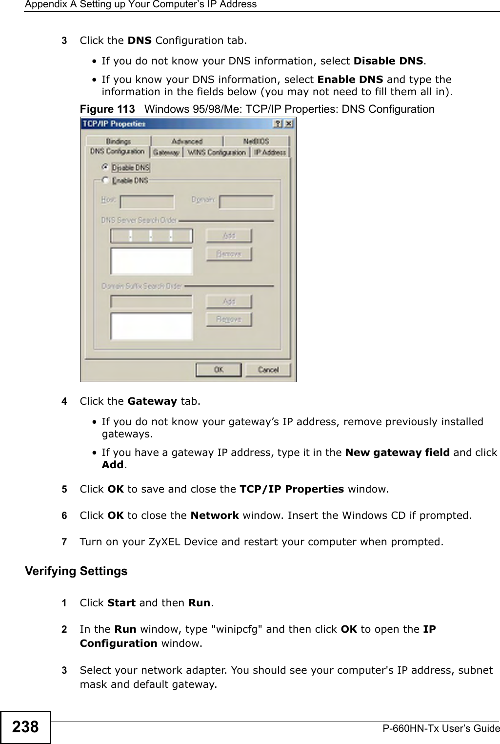
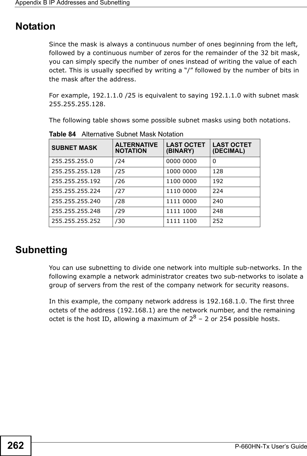
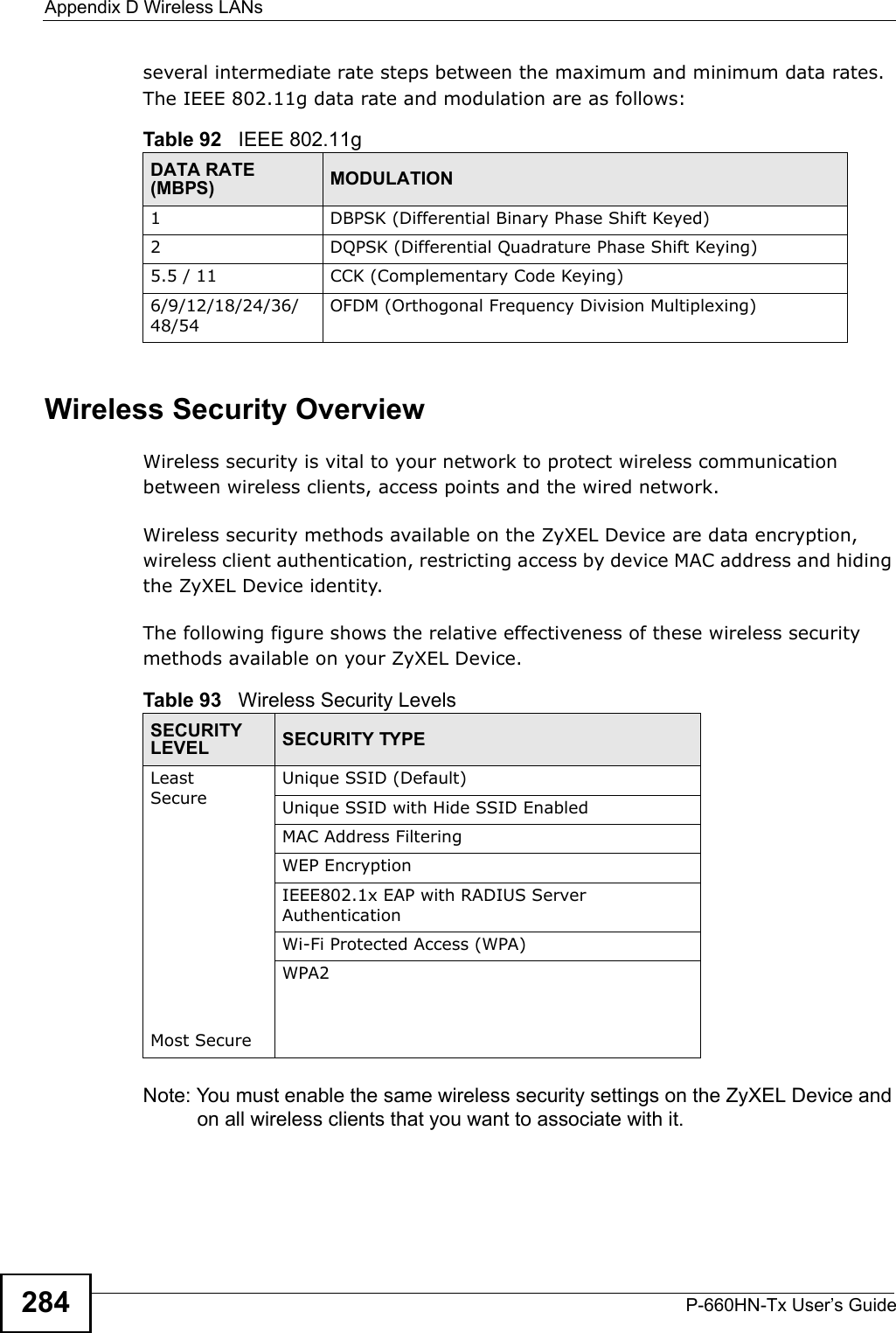
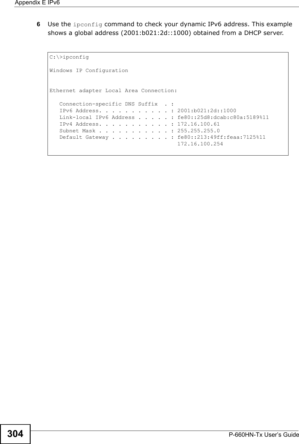
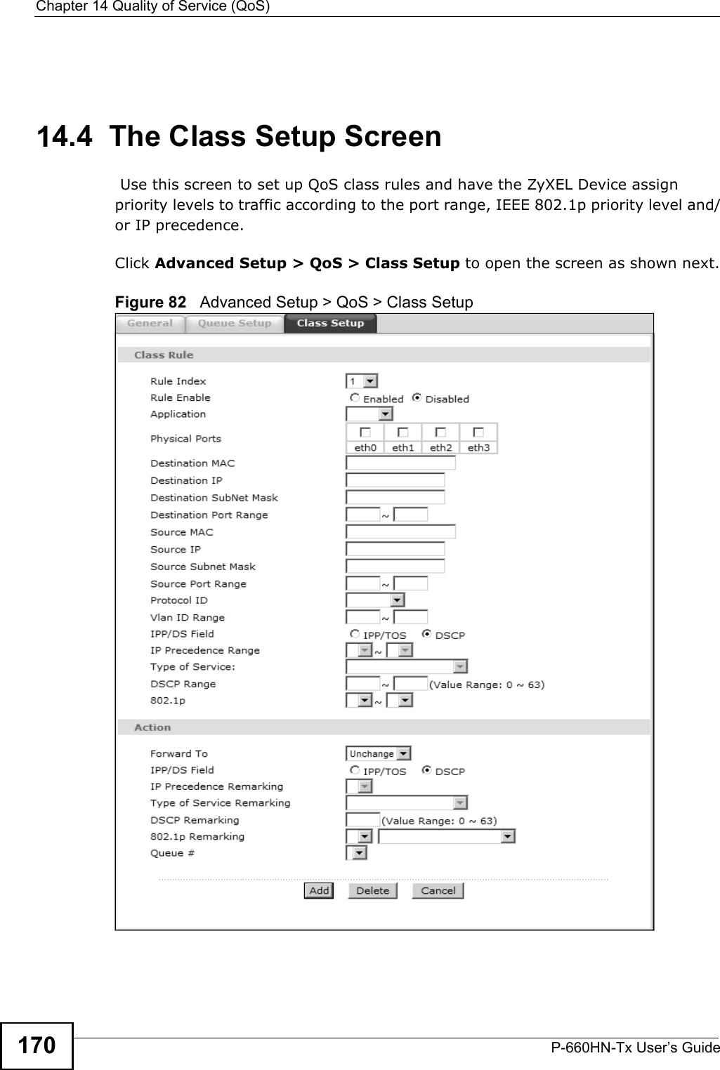
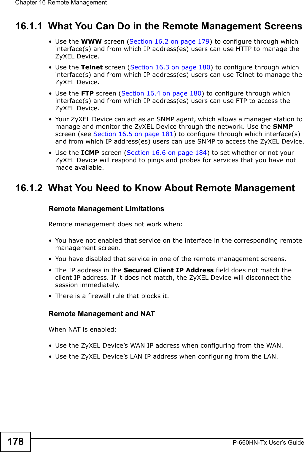
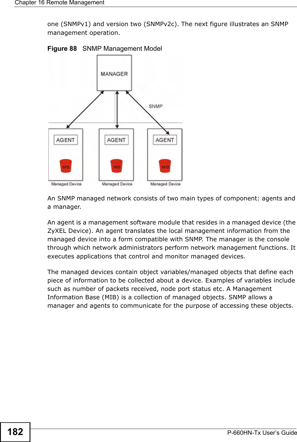
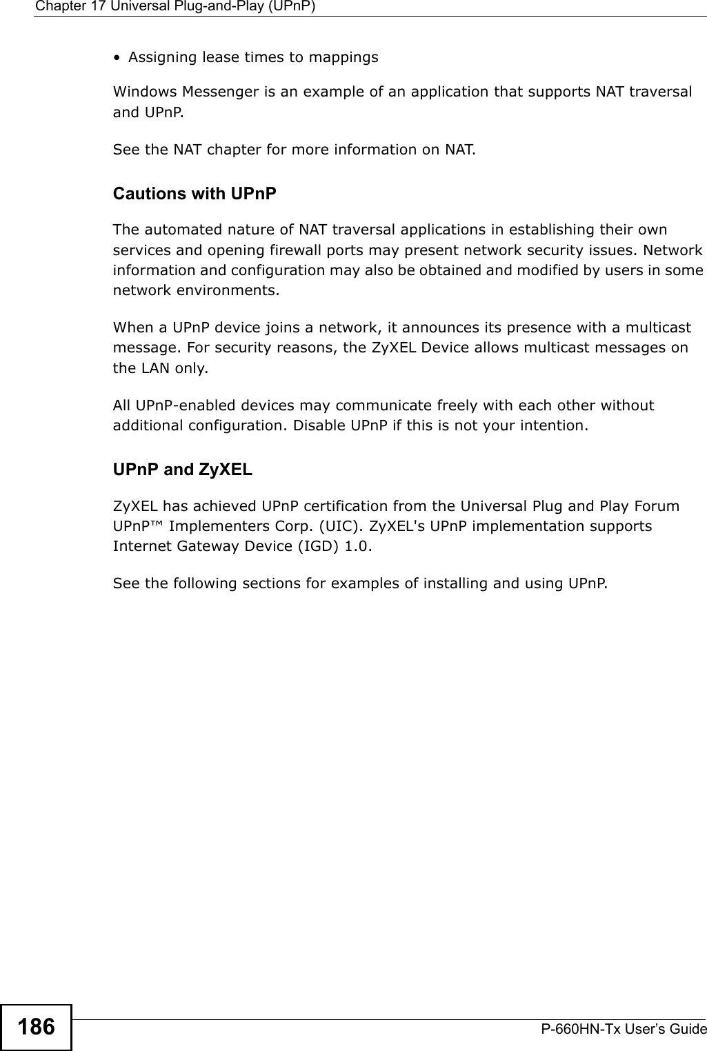
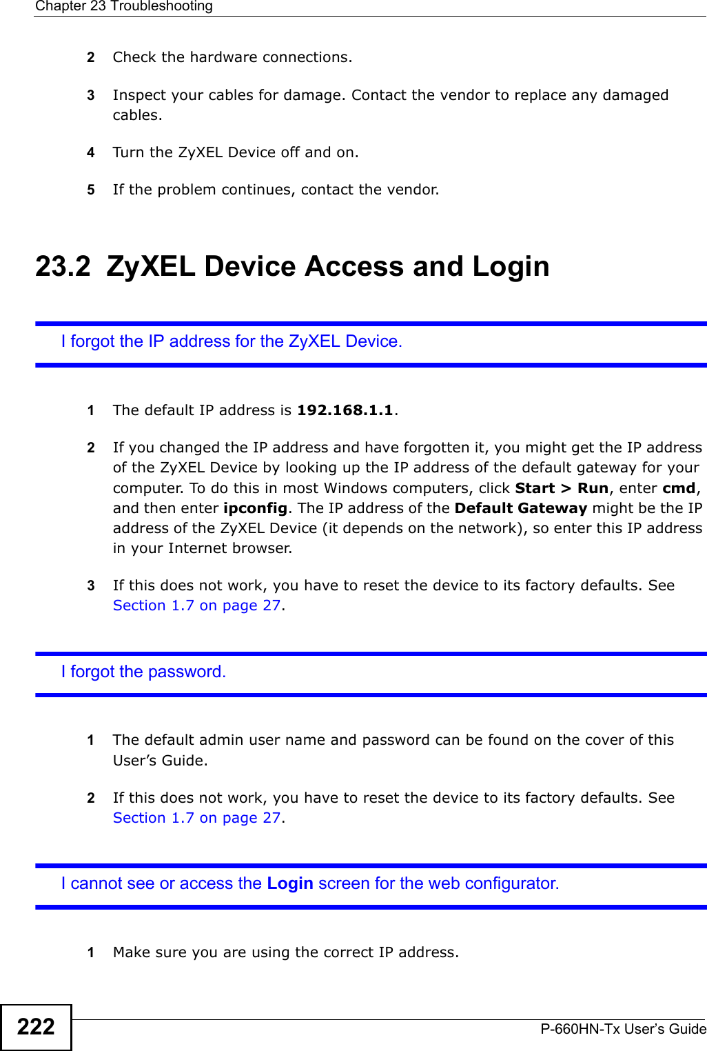
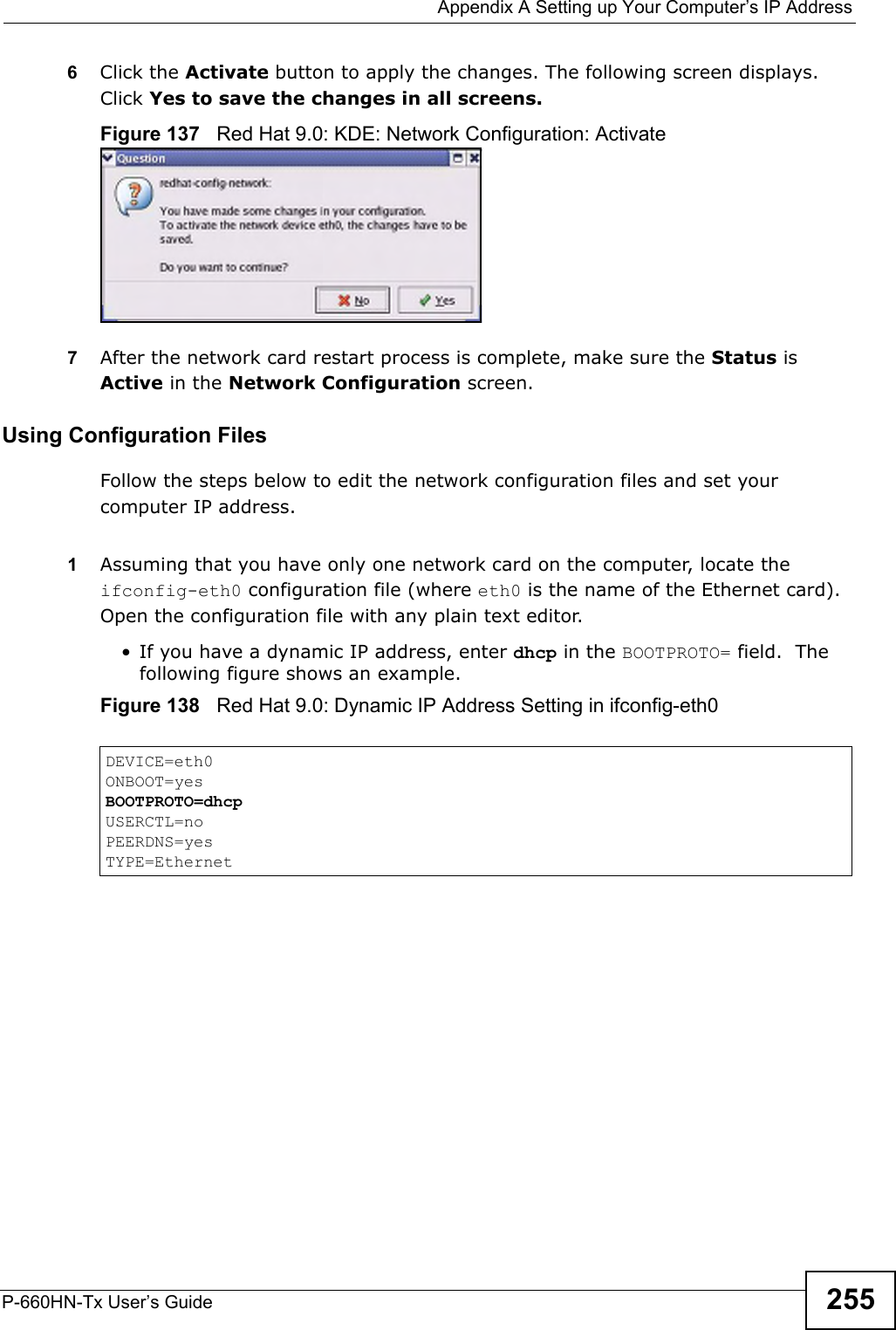
![Appendix A Setting up Your Computer’s IP AddressP-660HN-Tx User’s Guide 243If you have previously configured DNS servers, click Advanced and then the DNS tab to order them.Figure 120 Windows XP: Internet Protocol (TCP/IP) Properties8Click OK to close the Internet Protocol (TCP/IP) Properties window.9Click Close (OK in Windows 2000/NT) to close the Local Area Connection Properties window.10 Close the Network Connections window (Network and Dial-up Connections in Windows 2000/NT).11 Turn on your ZyXEL Device and restart your computer (if prompted).Verifying Settings1Click Start, All Programs, Accessories and then Command Prompt.2In the Command Prompt window, type "ipconfig" and then press [ENTER]. You can also open Network Connections, right-click a network connection, click Status and then click the Support tab.Windows VistaThis section shows screens from Windows Vista Enterprise Version 6.0.](https://usermanual.wiki/ZyXEL-Communications/P660HNT1.User-Manual-2/User-Guide-1442527-Page-93.png)
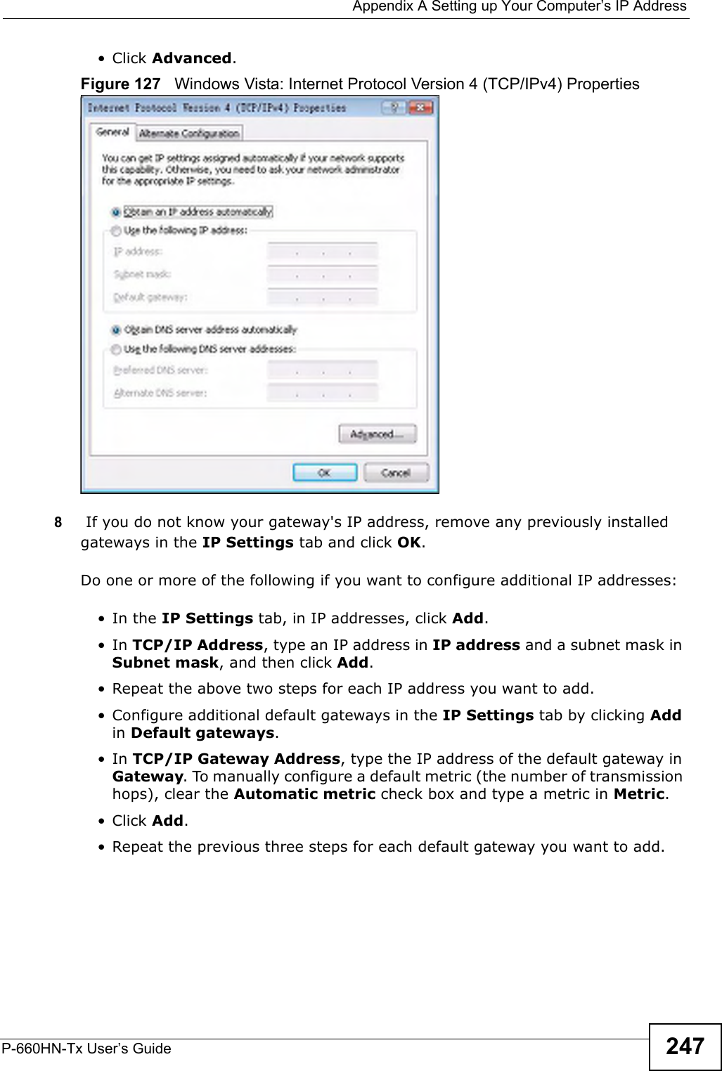
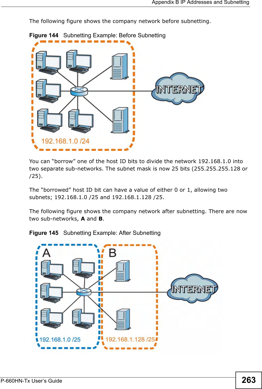
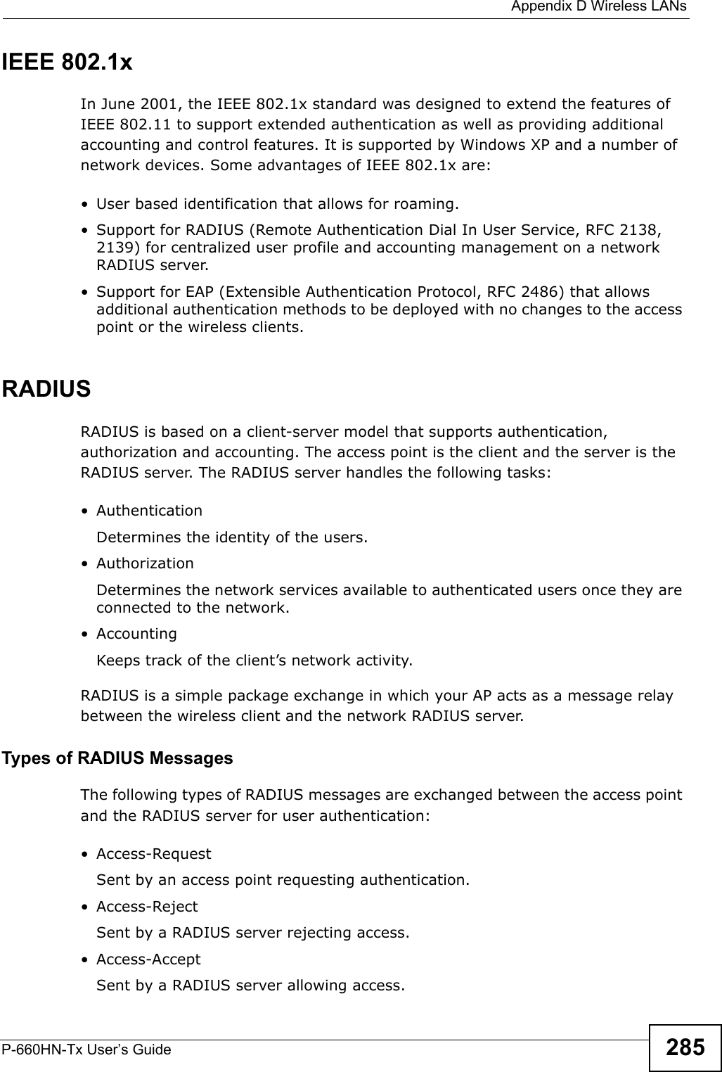
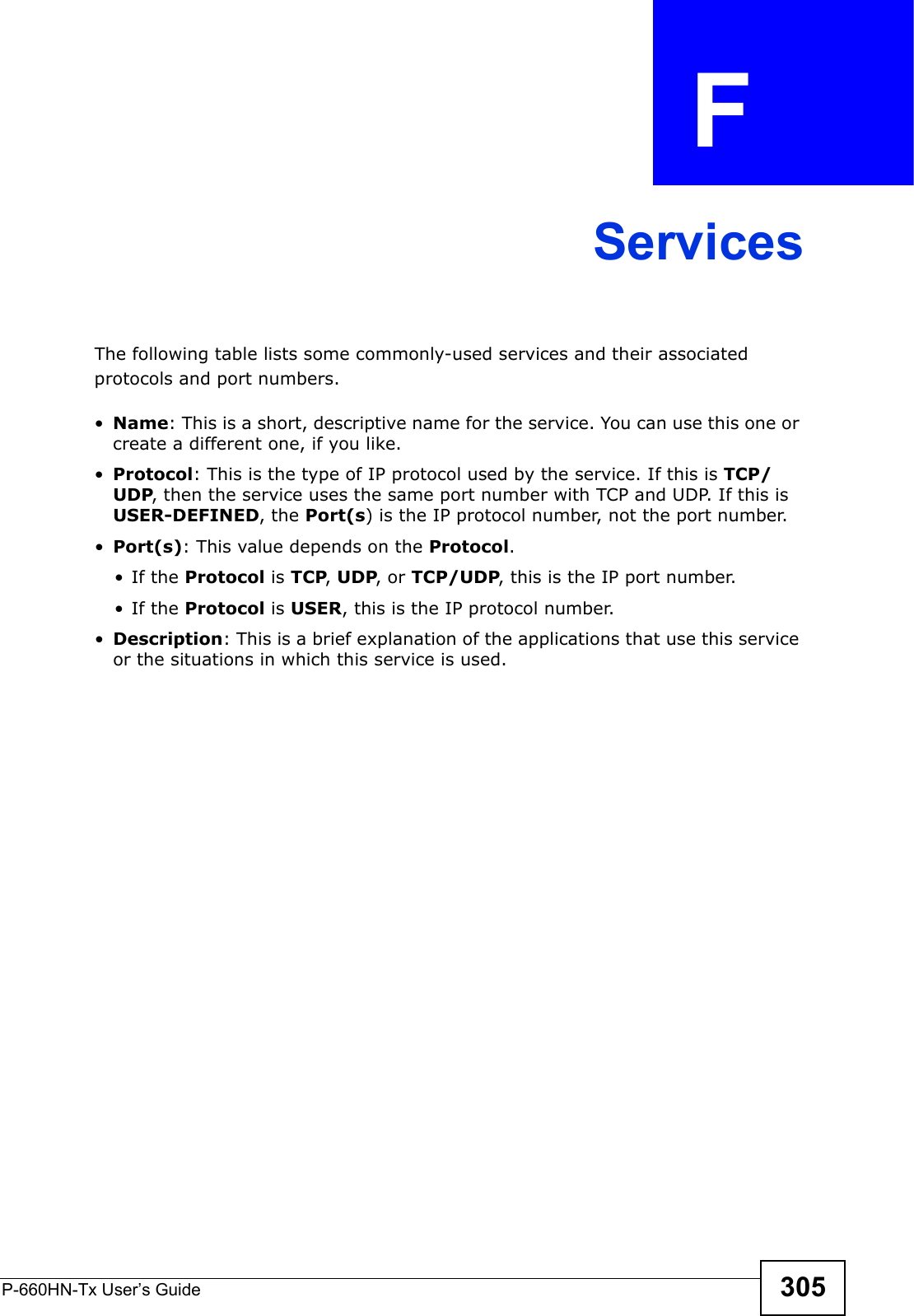
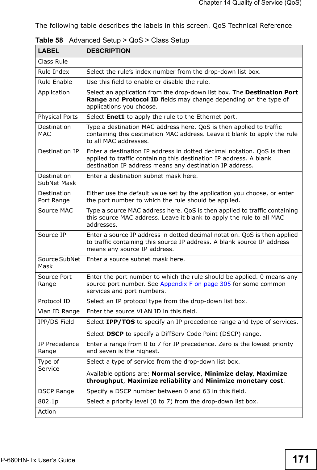
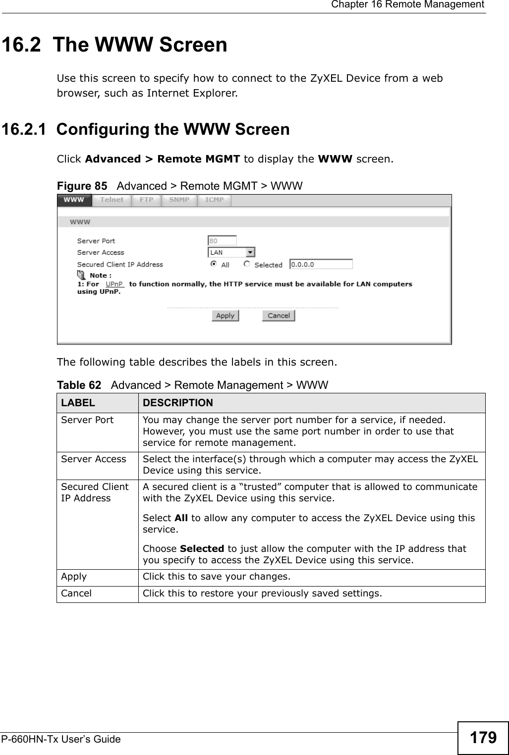
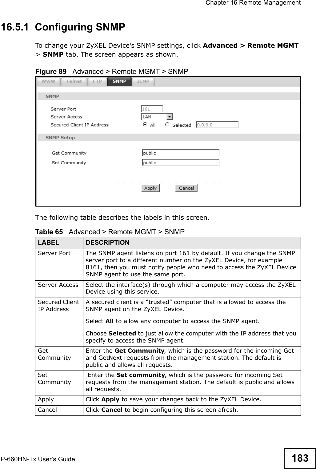
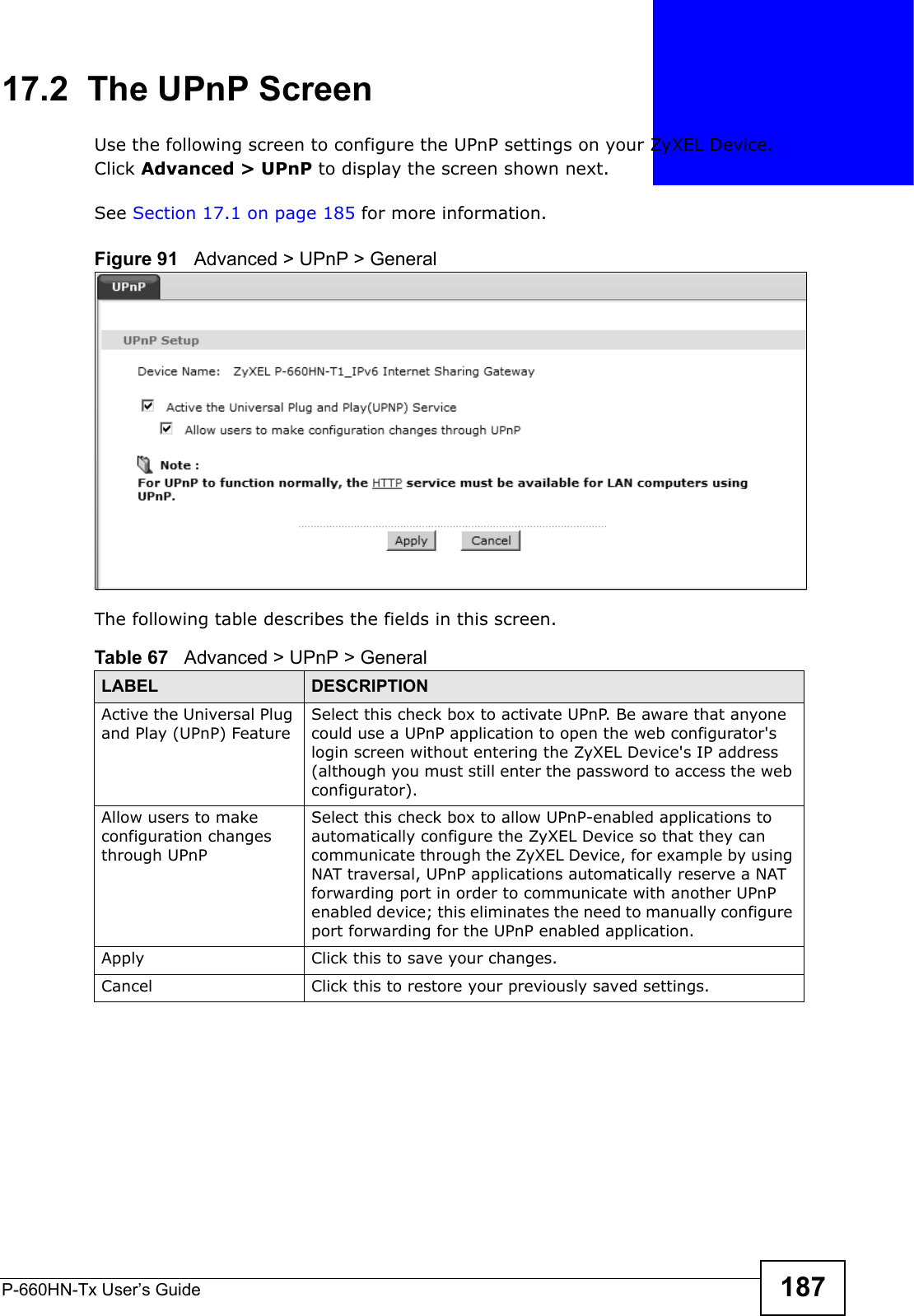
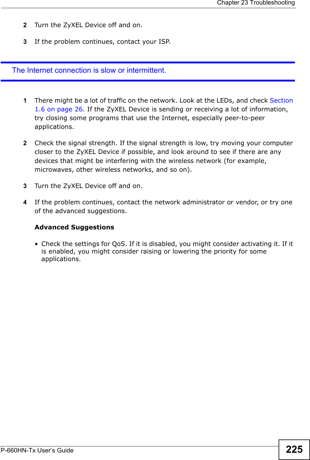
![Appendix A Setting up Your Computer’s IP AddressP-660HN-Tx User’s Guide 249If you have previously configured DNS servers, click Advanced and then the DNS tab to order them.Figure 129 Windows Vista: Internet Protocol Version 4 (TCP/IPv4) Properties10 Click OK to close the Internet Protocol Version 4 (TCP/IPv4) Properties window.11 Click Close to close the Local Area Connection Properties window.12 Close the Network Connections window.13 Turn on your ZyXEL Device and restart your computer (if prompted).Verifying Settings1Click Start, All Programs, Accessories and then Command Prompt.2In the Command Prompt window, type "ipconfig" and then press [ENTER]. You can also open Network Connections, right-click a network connection, click Status and then click the Support tab.](https://usermanual.wiki/ZyXEL-Communications/P660HNT1.User-Manual-2/User-Guide-1442527-Page-99.png)
![Appendix A Setting up Your Computer’s IP AddressP-660HN-Tx User’s Guide256•If you have a static IP address, enter static in the BOOTPROTO= field. Type IPADDR= followed by the IP address (in dotted decimal notation) and type NETMASK= followed by the subnet mask. The following example shows an example where the static IP address is 192.168.1.10 and the subnet mask is 255.255.255.0. Figure 139 Red Hat 9.0: Static IP Address Setting in ifconfig-eth0 2If you know your DNS server IP address(es), enter the DNS server information in the resolv.conf file in the /etc directory. The following figure shows an example where two DNS server IP addresses are specified.Figure 140 Red Hat 9.0: DNS Settings in resolv.conf 3After you edit and save the configuration files, you must restart the network card. Enter ./network restart in the /etc/rc.d/init.d directory. The following figure shows an example.Figure 141 Red Hat 9.0: Restart Ethernet Card DEVICE=eth0ONBOOT=yesBOOTPROTO=staticIPADDR=192.168.1.10NETMASK=255.255.255.0USERCTL=noPEERDNS=yesTYPE=Ethernetnameserver 172.23.5.1nameserver 172.23.5.2[root@localhost init.d]# network restartShutting down interface eth0: [OK]Shutting down loopback interface: [OK]Setting network parameters: [OK]Bringing up loopback interface: [OK]Bringing up interface eth0: [OK]](https://usermanual.wiki/ZyXEL-Communications/P660HNT1.User-Manual-2/User-Guide-1442527-Page-106.png)
![Appendix A Setting up Your Computer’s IP AddressP-660HN-Tx User’s Guide 257Verifying SettingsEnter ifconfig in a terminal screen to check your TCP/IP properties. Figure 142 Red Hat 9.0: Checking TCP/IP Properties [root@localhost]# ifconfig eth0 Link encap:Ethernet HWaddr 00:50:BA:72:5B:44 inet addr:172.23.19.129 Bcast:172.23.19.255 Mask:255.255.255.0 UP BROADCAST RUNNING MULTICAST MTU:1500 Metric:1 RX packets:717 errors:0 dropped:0 overruns:0 frame:0 TX packets:13 errors:0 dropped:0 overruns:0 carrier:0 collisions:0 txqueuelen:100 RX bytes:730412 (713.2 Kb) TX bytes:1570 (1.5 Kb) Interrupt:10 Base address:0x1000 [root@localhost]#](https://usermanual.wiki/ZyXEL-Communications/P660HNT1.User-Manual-2/User-Guide-1442527-Page-107.png)