ZyXEL Communications P660HNT1 802.11n Wireless ADSL2+ 4-port Gateway User Manual
ZyXEL Communications Corporation 802.11n Wireless ADSL2+ 4-port Gateway
Contents
- 1. Users Manual-1
- 2. User Manual-2
User Manual-2
Chapter 11 Filters
P-660HN-Tx User’s Guide 151
11.4 IPv6 Filter
Use this screen to create and apply IPv6 filters. Click Security > Filter > IPv6
Filter. The screen appears as shown.
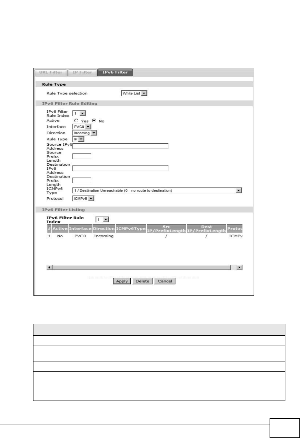
Figure 69 Security > Filter > IPv6 Filter
The following table describes the labels in this screen.
Table 47 Security > Filter > IPv6 Filter
LABEL DESCRIPTION
Rule Type
Rule Type selection Select White List to specify traffic to allow and Black List to
specify traffic to block.
IPv6 Filter Rule Editing
IPv6 Filter Rule Index Select the index number of the filter rule.
Active Use this field to enable or disable the filter rule.
Interface Select the PVC to which to apply the filter.

Chapter 11 Filters
P-660HN-Tx User’s Guide
152
Direction Apply the filter to Incoming or Outgoing traffic direction.
Rule Type Use the IPv6 filter to block or allow traffic by IPv6 addresses.
Source IPv6 Address Enter the source IPv6 address of the packets you wish to filter.
This field is ignored if it is ::.
Source Prefix Length Enter the prefix length for the source IPv6 address
Destination IPv6
Address
Enter the destination IPv6 address of the packets you wish to
filter. This field is ignored if it is ::.
Destination Prefix
Length
Enter the prefix length for the destination IPv6 address.
ICMPv6 Type Select the ICMPv6 message type to filter. The following
message types can be selected:
1 / Destination Unreachable: 0 - no route to destination; 1 -
communication with destination administratively prohibited; 3 -
address unreachable; 4 - port unreachable
2 / Packet Too Big
3 / Time Exceeded: 0 - hop limit exceeded in transit; 1 -
fragment reassembly time exceeded
4 / Parameter Problem: 0 - erroneous header field
encountered; 1 - unrecognized Next Header type encountered;
2 - unrecognized IPv6 option encountered
128 / Echo Request
129 / Echo Response
130 / Listener Query - Multicast listener query
131 / Listener Report - Multicast listener report
132 / Listener Done - Multicast listener done
143 / Listener Reportv2 - Multicast listener report v2
133 / Router Solicitation
134 / Router Advertisement
135 / Neighbor Solicitation
136 / Neighbor Advertisement
137 / Redirect - Redirect message
Protocol This is the (upper layer) protocol that defines the service to
which this rule applies. By default it is ICMPv6.
IPv6 Filter Listing
IPv6 Filter Rule Index Select the index number of the filter set from the drop-down list
box.
#This is the index number of the rule in a filter set.
Active This field shows whether the rule is activated.
Interface This is the interface that the rule applies to.
Table 47 Security > Filter > IPv6 Filter
LABEL DESCRIPTION

Chapter 11 Filters
P-660HN-Tx User’s Guide 153
Direction The filter set applies to this traffic direction.
ICMPv6 Type The ICMPv6 message type to filter.
Src IP/PrefixLength This displays the source IPv6 address and prefix length.
Dest IP/PrefixLength This displays the destination IPv6 address and prefix length.
Protocol This is the (upper layer) protocol that defines the service to
which this rule applies. By default it is ICMPv6.
Apply Click this to apply your changes.
Delete Click this to remove the filter rule.
Cancel Click this to restore your previously saved settings.
Table 47 Security > Filter > IPv6 Filter
LABEL DESCRIPTION

Chapter 11 Filters
P-660HN-Tx User’s Guide
154

P-660HN-Tx User’s Guide 155
CHAPTER 12
Certificate
12.1 Overview
The ZyXEL Device can use certificates (also called digital IDs) to authenticate
users. Certificates are based on public-private key pairs. A certificate contains the
certificate owner’s identity and public key. Certificates provide a way to exchange
public keys for use in authentication.
12.1.1 What You Can Do in this Chapter
•The Trusted CA screen lets you save the certificates of trusted CAs to the
ZyXEL Device (Section 12.3 on page 156).
12.2 What You Need to Know
The following terms and concepts may help as you read through this chapter.
Certification Authority
A Certification Authority (CA) issues certificates and guarantees the identity of
each certificate owner. There are commercial certification authorities like
CyberTrust or VeriSign and government certification authorities. The certification
authority uses its private key to sign certificates. Anyone can then use the
certification authority's public key to verify the certificates. You can use the ZyXEL
Device to generate certification requests that contain identifying information and
public keys and then send the certification requests to a certification authority.
Certificate File Format
The certification authority certificate that you want to import has to be in one of
these file formats:
• PEM (Base-64) encoded X.509: This Privacy Enhanced Mail format uses 64
ASCII characters to convert a binary X.509 certificate into a printable form.
Chapter 12 Certificate
P-660HN-Tx User’s Guide
156
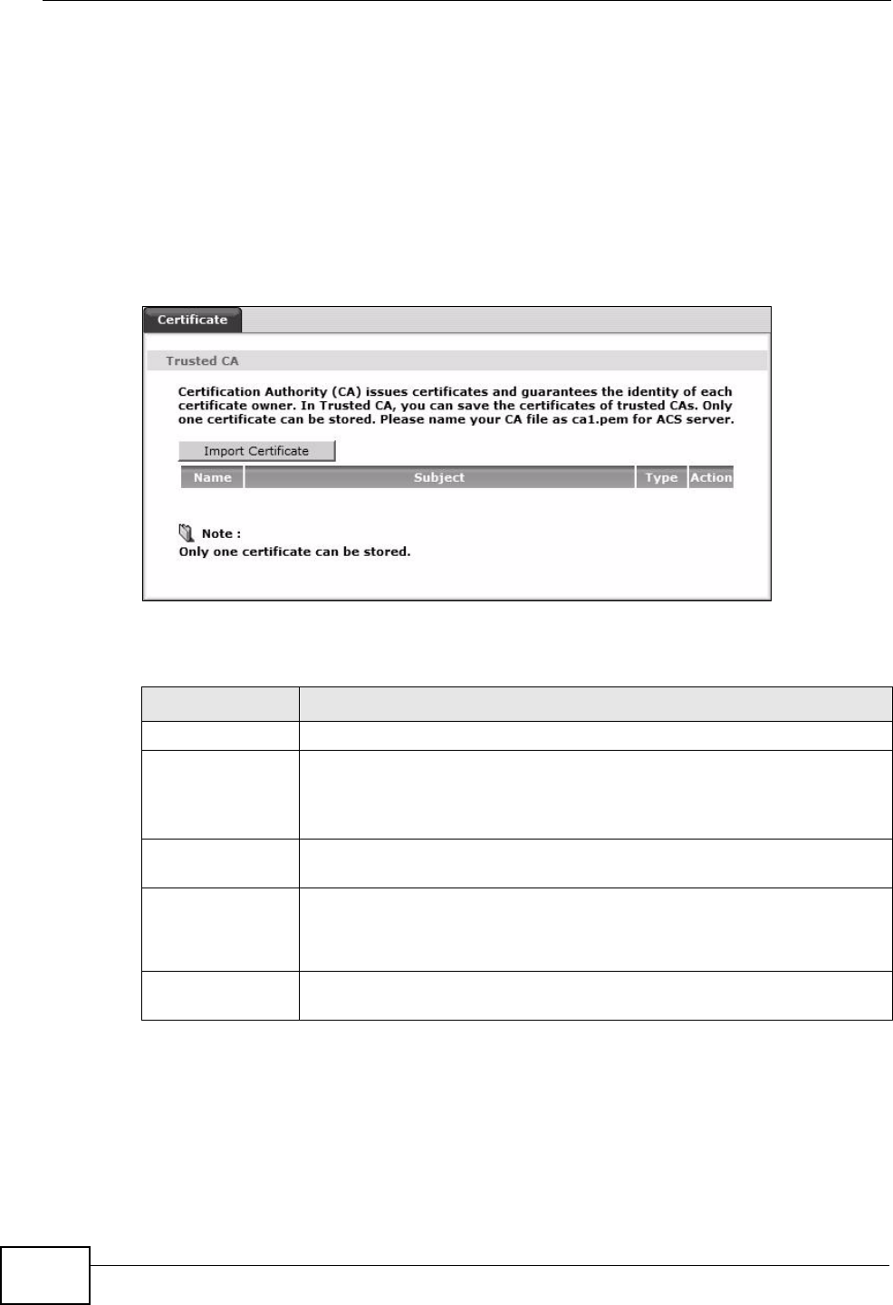
12.3 The Trusted CA Screen
Click Security > Certificates to open the following screen. This screen displays a
summary list of certificates of the certification authorities that you have set the
ZyXEL Device to accept as trusted. The ZyXEL Device accepts any valid certificate
signed by a certification authority on this list as being trustworthy; thus you do
not need to import any certificate that is signed by one of these certification
authorities.
Figure 70 Trusted CA
The following table describes the fields in this screen.
Table 48 Trusted CA
LABEL DESCRIPTION
Name This field displays the name used to identify this certificate.
Subject This field displays information that identifies the owner of the
certificate, such as Common Name (CN), OU (Organizational Unit or
department), Organization (O), State (ST) and Country (C). It is
recommended that each certificate have unique subject information.
Type This field displays general information about the certificate. ca means
that a Certification Authority signed the certificate.
Action Click View to open a screen with an in-depth list of information about
the certificate.
Click Remove to delete the certificate.
Import
Certificate
Click this button to open a screen where you can save the certificate of
a certification authority that you trust to the ZyXEL Device.
Chapter 12 Certificate
P-660HN-Tx User’s Guide 157
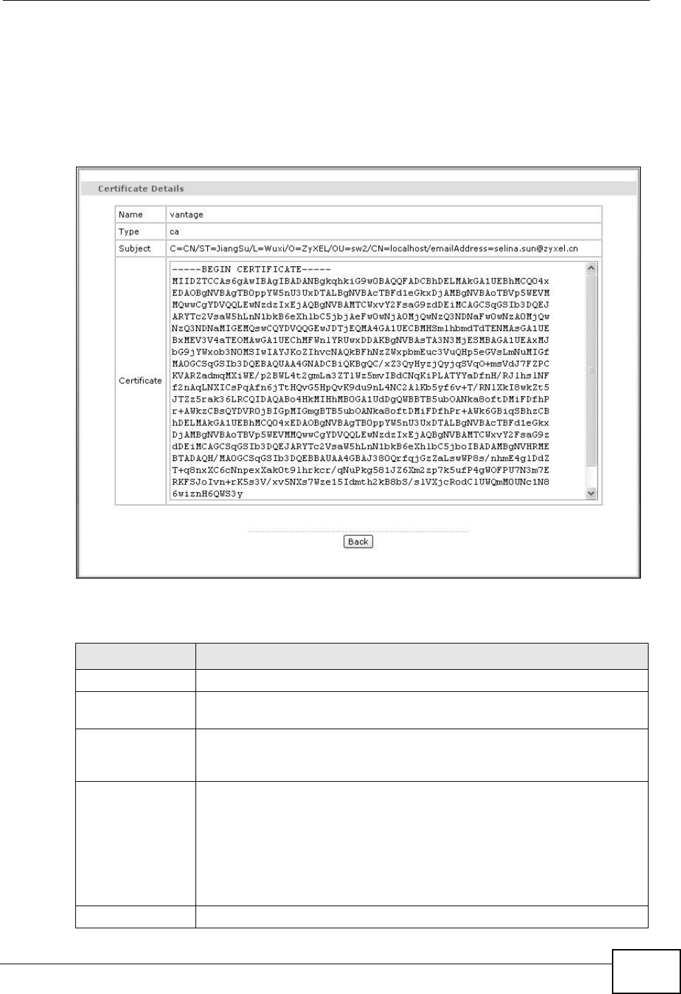
12.3.1 View Trusted CA Certificate
Click the View button in the Trusted CA screen to open the following screen. Use
this screen to view in-depth information about the certification authority’s
certificate.
Figure 71 Trusted CA: View
The following table describes the fields in this screen.
Table 49 Trusted CA: View
LABEL DESCRIPTION
Name This field displays the identifying name of this certificate.
Type This field displays general information about the certificate. ca means
that a Certification Authority signed the certificate.
Subject This field displays information that identifies the owner of the
certificate, such as Common Name (CN), Organizational Unit (OU),
Organization (O) and Country (C).
Certificate This read-only text box displays the certificate in Privacy Enhanced
Mail (PEM) format. PEM uses 64 ASCII characters to convert the binary
certificate into a printable form.
You can copy and paste the certificate into an e-mail to send to friends
or colleagues or you can copy and paste the certificate into a text
editor and save the file on a management computer for later
distribution (via floppy disk for example).
Back Click this button to return to the previous screen.
Chapter 12 Certificate
P-660HN-Tx User’s Guide
158
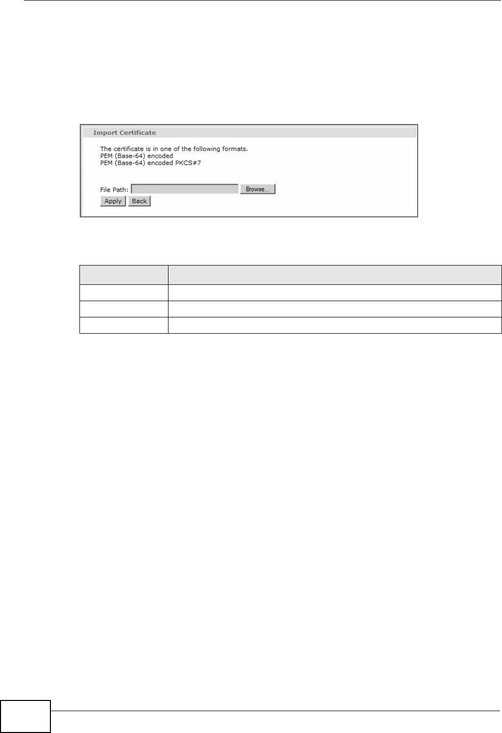
12.3.2 Import Trusted CA Certificate
Click the Import Certificate button in the Trusted CA screen to open the
following screen. The ZyXEL Device trusts any valid certificate signed by any of
the imported trusted CA certificates.
Figure 72 Trusted CA: Import Certificate
The following table describes the fields in this screen.
Table 50 Trusted CA: Import Certificate
LABEL DESCRIPTION
Browse Click this button to locate the certificate file on your computer.
Back Click this button to return to the previous screen.
Apply Click this button to save your changes back to the ZyXEL Device.
P-660HN-Tx User’s Guide 159
CHAPTER 13
Static Route
13.1 Overview
The ZyXEL Device usually uses the default gateway to route outbound traffic from
computers on the LAN to the Internet. To have the ZyXEL Device send data to
devices not reachable through the default gateway, use static routes.
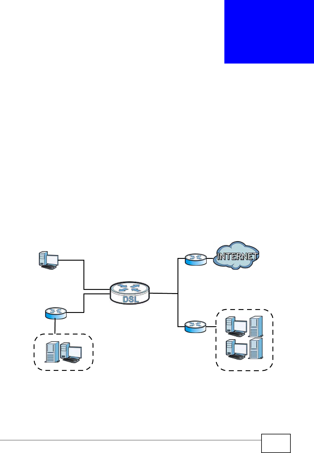
For example, the next figure shows a computer (A) connected to the ZyXEL
Device’s LAN interface. The ZyXEL Device routes most traffic from A to the
Internet through the ZyXEL Device’s default gateway (R1). You create one static
route to connect to services offered by your ISP behind router R2. You create
another static route to communicate with a separate network behind a router R3
connected to the LAN.
Figure 73 Example of Static Routing Topology
WAN
R1
R2
A
R3
LAN
Chapter 13 Static Route
P-660HN-Tx User’s Guide
160
13.1.1 What You Can Do in the Static Route Screens
•Use the Static Route screens (Section 13.2 on page 160) to view and configure
IP static routes on the ZyXEL Device.
•Use the IPv6 Static Route screens (Section 13.2.2 on page 162) to view and
configure IPv6 static routes on the ZyXEL Device.
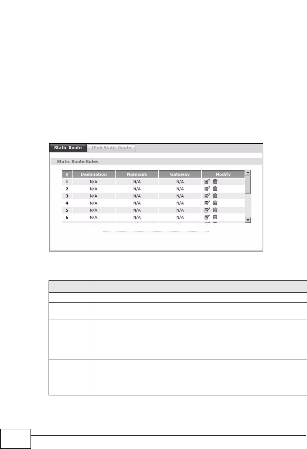
13.2 The Static Route Screen
Use this screen to view the static route rules. Click Advanced > Static Route to
open the Static Route screen.
Figure 74 Advanced > Static Route
The following table describes the labels in this screen.
Table 51 Advanced > Static Route
LABEL DESCRIPTION
#This is the number of an individual static route.
Destination This parameter specifies the IP network address of the final destination.
Routing is always based on network number.
Netmask This parameter specifies the IP network subnet mask of the final
destination.
Gateway This is the IP address of the gateway. The gateway is a router or switch
on the same network segment as the device's LAN or WAN port. The
gateway helps forward packets to their destinations.
Modify Click the Edit icon to go to the screen where you can set up a static route
on the ZyXEL Device.
Click the Remove icon to remove a static route from the ZyXEL Device. A
window displays asking you to confirm that you want to delete the route.
Chapter 13 Static Route
P-660HN-Tx User’s Guide 161
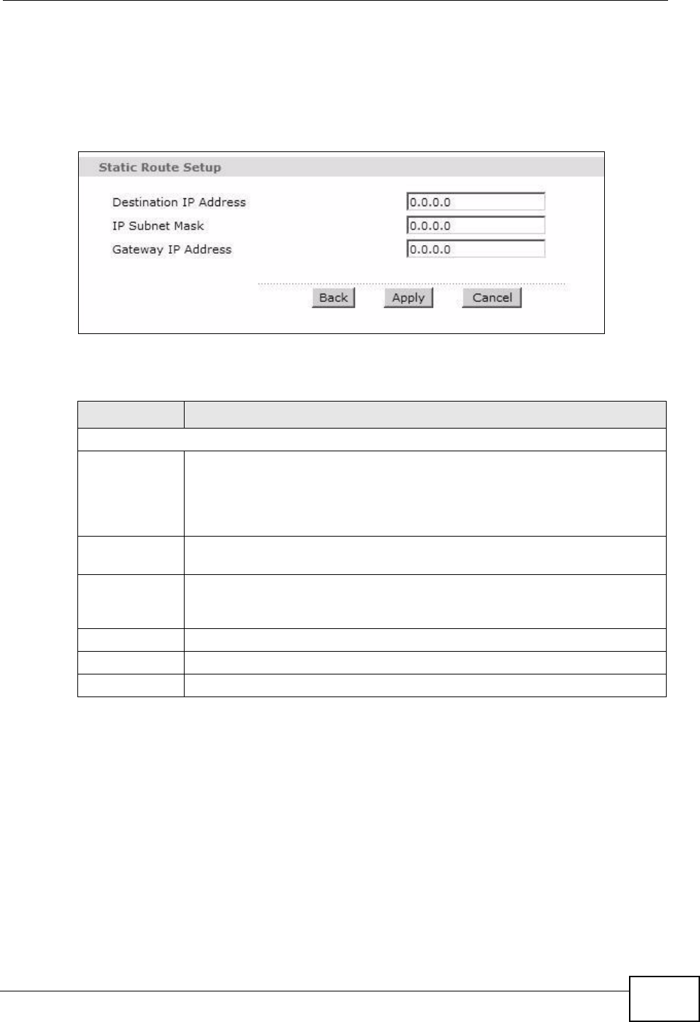
13.2.1 Static Route Edit
Use this screen to configure the required information for a static route. Select a
static route index number and click Edit. The screen shown next appears.
Figure 75 Advanced > Static Route: Edit
The following table describes the labels in this screen.
Table 52 Advanced > Static Route: Edit
LABEL DESCRIPTION
Static Route Setup
Destination IP
Address
This parameter specifies the IP network address of the final destination.
Routing is always based on network number. If you need to specify a
route to a single host, use a subnet mask of 255.255.255.255 in the
subnet mask field to force the network number to be identical to the host
ID.
IP Subnet
Mask
Enter the IP subnet mask here.
Gateway IP
Address
Enter the IP address of the gateway. The gateway is a router or switch on
the same network segment as the device's LAN or WAN port. The
gateway helps forward packets to their destinations.
Back Click this to return to the previous screen without saving.
Apply Click this to save your changes.
Cancel Click this to restore your previously saved settings.
Chapter 13 Static Route
P-660HN-Tx User’s Guide
162
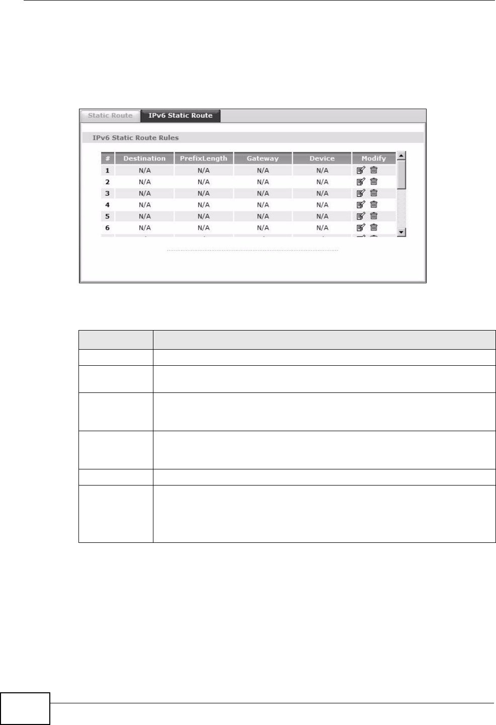
13.2.2 IPv6 Static Route
Use this screen to view the IPv6 static route rules. Click Advanced > Static
Route > IPv6 Static Route to open the IPv6 Static Route screen.
Figure 76 Advanced > Static Route > IPv6 Static Route
The following table describes the labels in this screen.
Table 53 Advanced > Static Route > IPv6 Static Route
LABEL DESCRIPTION
#This is the number of an individual static route.
Destination This parameter specifies the IP network address of the final destination.
Routing is always based on network number.
Prefix Length An IPv6 prefix length specifies how many most significant bits (starting
from the left) in the address compose the network address. This field
displays the bit number of the IPv6 subnet mask.
Gateway This is the IP address of the gateway. The gateway is a router or switch
on the same network segment as the device's LAN or WAN port. The
gateway helps forward packets to their destinations.
Device This specifies the LAN or WAN PVC.
Modify Click the Edit icon to go to the screen where you can set up a static route
on the ZyXEL Device.
Click the Remove icon to remove a static route from the ZyXEL Device. A
window displays asking you to confirm that you want to delete the route.
Chapter 13 Static Route
P-660HN-Tx User’s Guide 163
13.2.3 IPv6 Static Route Edit
Use this screen to configure the required information for an IPv6 static route.
Select an IPv6 static route index number and click Edit. The screen shown next
appears.
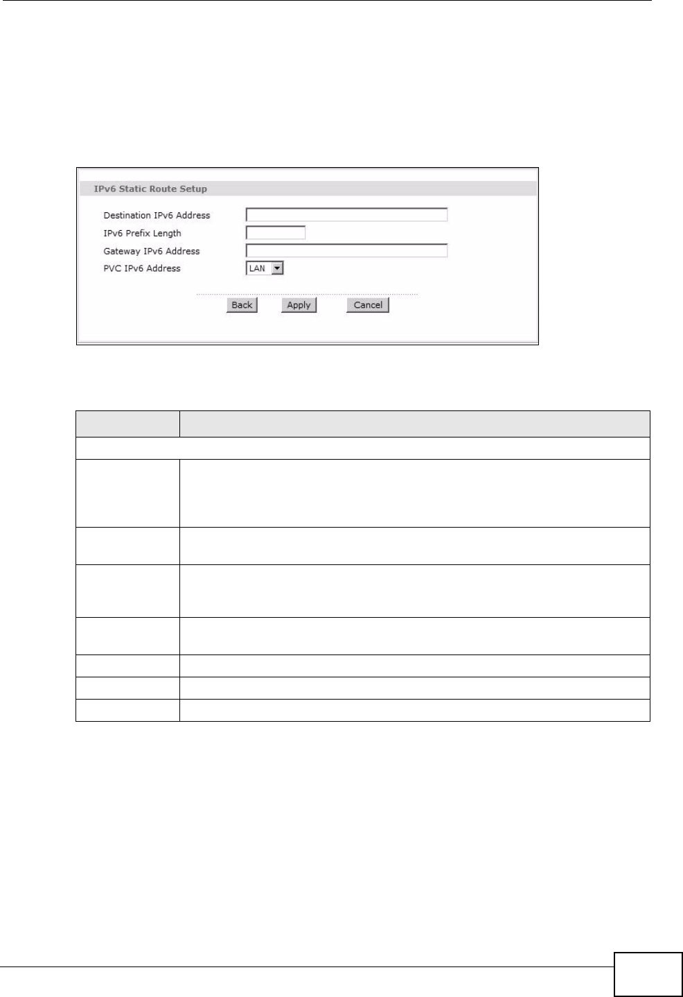
Figure 77 Advanced > Static Route > IPv6 Static Route: Edit
The following table describes the labels in this screen.
Table 54 Advanced > Static Route > IPv6 Static Route: Edit
LABEL DESCRIPTION
Static Route Setup
Destination
IPv6 Address
This parameter specifies the IP network address of the final destination.
Routing is always based on network number. If you need to specify a
route to a single host, use a prefix length of 128 in the prefix length field
to force the network number to be identical to the host ID.
IPv6 Prefix
Length
Enter the address prefix to specify how many most significant bits
compose the network address.
Gateway IPv6
Address
Enter the IP address of the gateway. The gateway is a router or switch on
the same network segment as the device's LAN or WAN port. The
gateway helps forward packets to their destinations.
PVC IPv6
Address
Select the interface through which the traffic is routed.
Back Click this to return to the previous screen without saving.
Apply Click this to save your changes.
Cancel Click this to restore your previously saved settings.

Chapter 13 Static Route
P-660HN-Tx User’s Guide
164

P-660HN-Tx User’s Guide 165
CHAPTER 14
Quality of Service (QoS)
14.1 Overview
Use the QoS screen to set up your ZyXEL Device to use QoS for traffic
management.
Quality of Service (QoS) refers to both a network’s ability to deliver data with
minimum delay, and the networking methods used to control bandwidth. QoS
allows the ZyXEL Device to group and prioritize application traffic and fine-tune
network performance.
Without QoS, all traffic data are equally likely to be dropped when the network is
congested. This can cause a reduction in network performance and make the
network inadequate for time-critical applications such as video-on-demand.
The ZyXEL Device assigns each packet a priority and then queues the packet
accordingly. Packets assigned with a high priority are processed more quickly than
those with low priorities if there is congestion, allowing time-sensitive applications
to flow more smoothly. Time-sensitive applications include both those that require
a low level of latency (delay) and a low level of jitter (variations in delay) such as
Voice over IP (VoIP) or Internet gaming, and those for which jitter alone is a
problem such as Internet radio or streaming video.
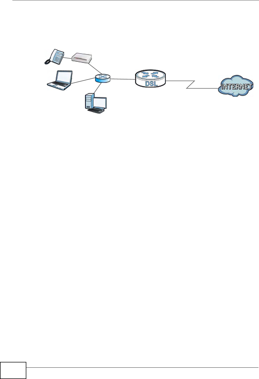
In the following figure, your Internet connection has an upstream transmission
speed of 50 Mbps. You configure a classifier to assign the highest priority queue
(6) to VoIP traffic from the LAN interface, so that voice traffic would not get
delayed when there is network congestion. Traffic from the boss’s IP address
(192.168.1.23 for example) is mapped to queue 5. Traffic that does not match
Chapter 14 Quality of Service (QoS)
P-660HN-Tx User’s Guide
166
these two classes are assigned priority queue based on the internal QoS mapping
table on the ZyXEL Device.
Figure 78 QoS Example
14.1.1 What You Can Do in the QoS Screens
•Use the General screen (Section 14.2 on page 167) to enable QoS on the
ZyXEL Device, and specify the type of scheduling.
•Use the QoS Summary List screen (Section 14.2.1 on page 168) to check the
summary of QoS rules and actions you configured for the ZyXEL Device.
•Use the Queue Setup screen (Section 14.3 on page 168) to configure QoS
settings on the ZyXEL Device.
•Use the Class Setup screen (Section 14.4 on page 170) to configure QoS
settings on the ZyXEL Device.
14.1.2 What You Need to Know About QoS
802.1p
QoS is used to prioritize source-to-destination traffic flows. All packets in the same
flow are given the same priority. 802.1p is a way of managing traffic in a network
by grouping similar types of traffic together and treating each type as a class. You
can use 802.1p to give different priorities to different packet types.
Tagging and Marking
In a QoS class, you can configure whether to add or change the DiffServ Code
Point (DSCP) value and IEEE 802.1p priority level in a matched packet. When the
packet passes through a compatible network, the networking device, such as a
backbone switch, can provide specific treatment or service based on the tag or
marker.
50 Mbps
DSL
VoIP: Queue 6
Boss: Queue 5
IP=192.168.1.23
Chapter 14 Quality of Service (QoS)
P-660HN-Tx User’s Guide 167
Finding Out More
See Section on page 171 for advanced technical information on QoS.
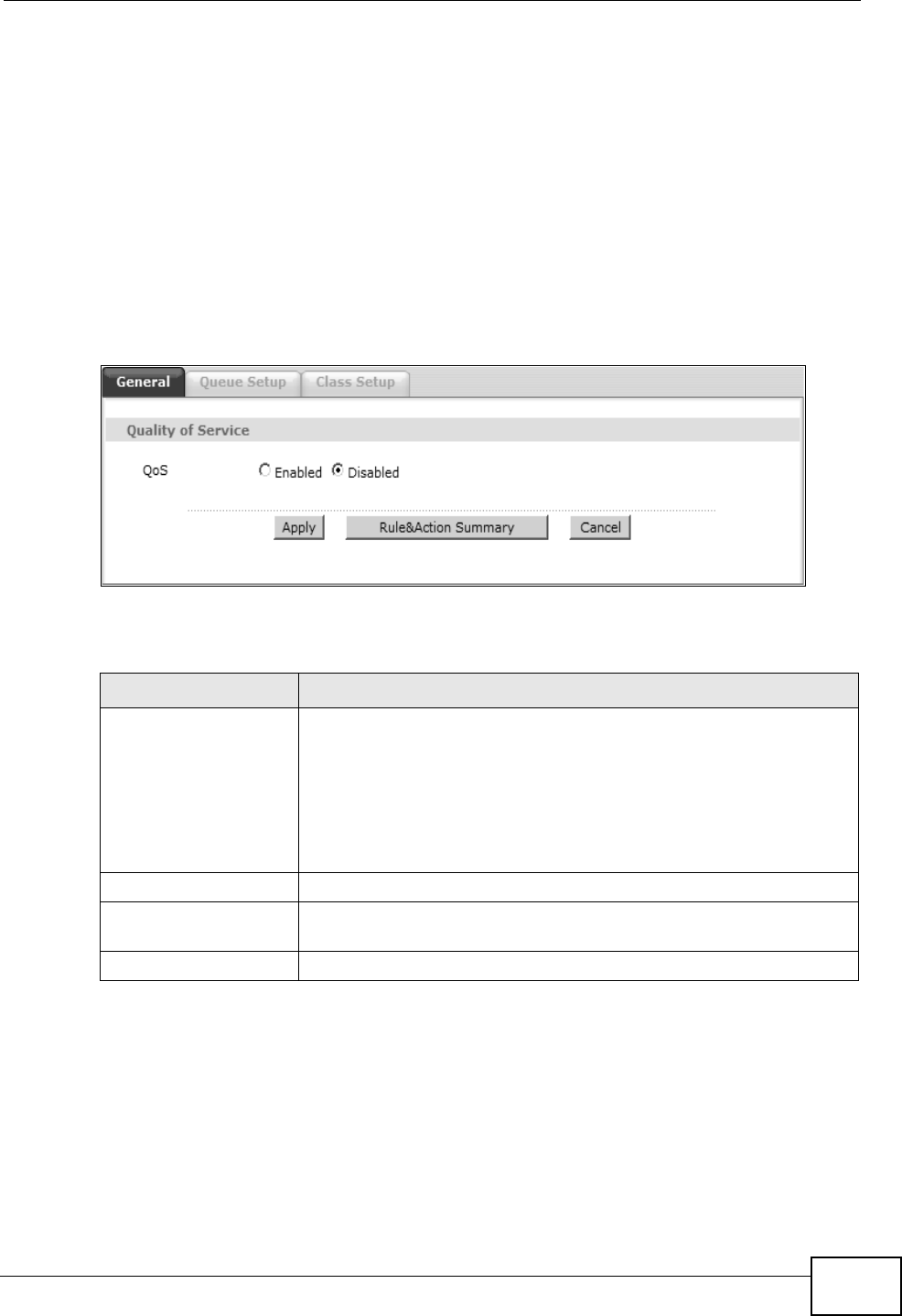
14.2 The General Screen
Use this screen to enable or disable QoS.
Click Advanced Setup > QoS to open the screen as shown next.
Figure 79 Advanced Setup > QoS
The following table describes the labels in this screen.
Table 55 Advanced Setup > QoS
LABEL DESCRIPTION
QoS Use this field to turn on QoS to improve your network
performance.
You can give priority to traffic that the ZyXEL Device forwards out
through the WAN interface. Give high priority to voice and video
to make them run more smoothly. Similarly, give low priority to
many large file downloads so that they do not reduce the quality
of other applications.
Apply Click this to save your changes.
Rule&Action
Summary
Click this to display a summary of configured rules and actions.
Cancel Click this to restore your previously saved settings.
Chapter 14 Quality of Service (QoS)
P-660HN-Tx User’s Guide
168
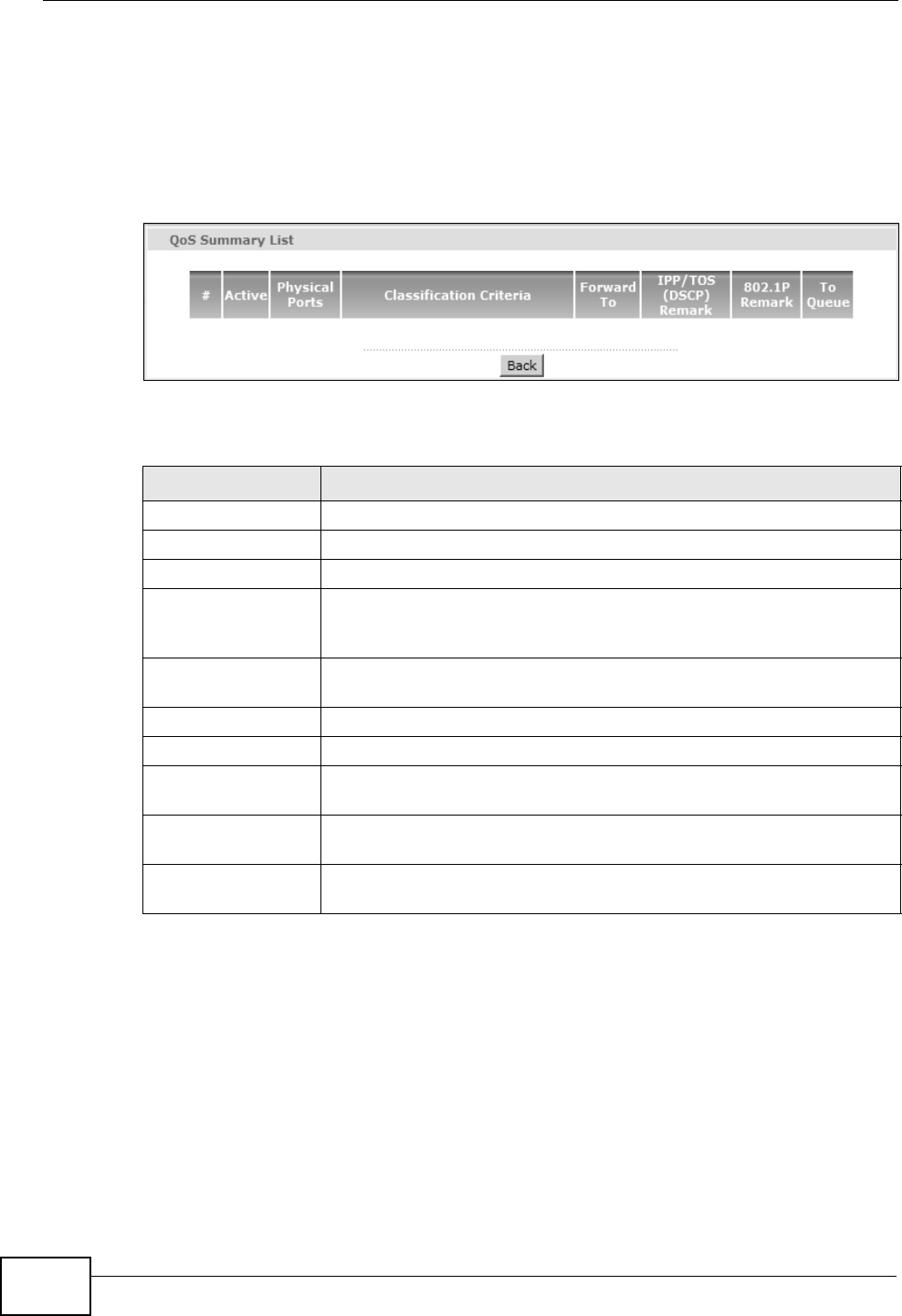
14.2.1 The QoS Summary List Screen
Use this screen to display a summary of rules and actions configured for the
ZyXEL Device. In the Advanced > QoS screen, click the Rule&Action Summary
button to open the following screen.
Figure 80 Advanced Setup > QoS > QoS Summary List
The following table describes the labels in this screen.
14.3 The Queue Setup Screen
Use this screen to configure QoS queue disciplines and priorities.
Table 56 Advanced Setup > QoS > QoS Summary List
LABEL DESCRIPTION
#This is the rule’s index number.
Active This shows whether the rule is enabled or disabled.
Physical Ports This is the physical port associated with the rule.
Classification
Criteria
This shows criteria specified in this rule, for example the interface
from which traffic of this class should come and the source MAC
address of traffic that matches this classifier.
Forward To This is the interface through which traffic that matches the rule is
forwarded out.
IPP/TOS (DSCP) This shows the IPP/TOS or DSCP settings.
802.1p This is the 802.1p priority level.
IPP/TOS (DSCP)
Remarking
The ZyXEL Device re-assigns the priority values specified in this field
to matched traffic.
802.1p Remarking The ZyXEL Device re-assigns the priority levels specified in this field
to matched traffic.
To Queue The ZyXEL Device assigns the queue level specified in this field to
matched traffic.
Chapter 14 Quality of Service (QoS)
P-660HN-Tx User’s Guide 169
Click Advanced Setup > QoS > Queue Setup to open the screen as shown
next.
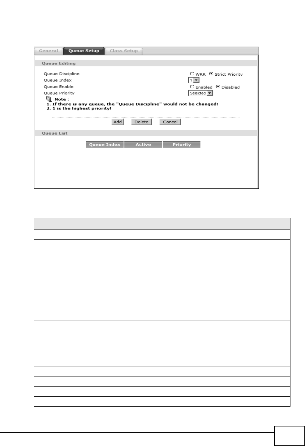
Figure 81 Advanced Setup > QoS > Queue Setup
The following table describes the labels in this screen.
Table 57 Advanced Setup > QoS > Queue Setup
LABEL DESCRIPTION
Queue Editing
Queue Discipline Select weighted round-robin (WRR) scheduling to allow packets
of all priorities to transmit depending on their assigned relative
weight. Select Strict Priority to require traffic transmit in order
of priority.
Queue Index Specify the queue index.
Queue Enable Specify to enable or disable the queue.
Queue Weight If you selected WRR, specify the WRR weight for each queue
index. A higher weight indicates higher priority while a lower
weight indicates lower priority. For example, 15 is higher priority
than 1.
Queue Priority If you selected strict priority, specify the queue priority for each
queue index.
Add Click this to add the queue to the list.
Delete Click this to delete the specified queue index.
Cancel Click this to restore your previously saved settings.
Queue List
Queue Index This is the specified queue index.
Active This specifies if the queue is enabled or disabled.
Priority This specifies the assigned priority.
Chapter 14 Quality of Service (QoS)
P-660HN-Tx User’s Guide
170
14.4 The Class Setup Screen
Use this screen to set up QoS class rules and have the ZyXEL Device assign
priority levels to traffic according to the port range, IEEE 802.1p priority level and/
or IP precedence.
Click Advanced Setup > QoS > Class Setup to open the screen as shown next.
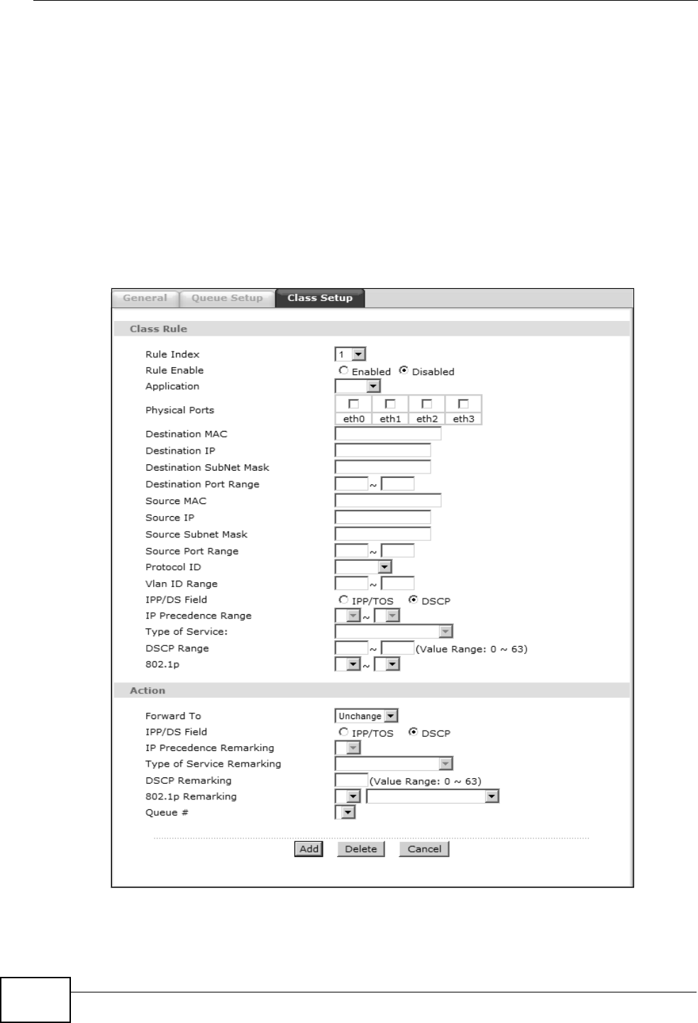
Figure 82 Advanced Setup > QoS > Class Setup

Chapter 14 Quality of Service (QoS)
P-660HN-Tx User’s Guide 171
The following table describes the labels in this screen. QoS Technical Reference
Table 58 Advanced Setup > QoS > Class Setup
LABEL DESCRIPTION
Class Rule
Rule Index Select the rule’s index number from the drop-down list box.
Rule Enable Use this field to enable or disable the rule.
Application Select an application from the drop-down list box. The Destination Port
Range and Protocol ID fields may change depending on the type of
applications you choose.
Physical Ports Select Enet1 to apply the rule to the Ethernet port.
Destination
MAC
Type a destination MAC address here. QoS is then applied to traffic
containing this destination MAC address. Leave it blank to apply the rule
to all MAC addresses.
Destination IP Enter a destination IP address in dotted decimal notation. QoS is then
applied to traffic containing this destination IP address. A blank
destination IP address means any destination IP address.
Destination
SubNet Mask
Enter a destination subnet mask here.
Destination
Port Range
Either use the default value set by the application you choose, or enter
the port number to which the rule should be applied.
Source MAC Type a source MAC address here. QoS is then applied to traffic containing
this source MAC address. Leave it blank to apply the rule to all MAC
addresses.
Source IP Enter a source IP address in dotted decimal notation. QoS is then applied
to traffic containing this source IP address. A blank source IP address
means any source IP address.
Source SubNet
Mask
Enter a source subnet mask here.
Source Port
Range
Enter the port number to which the rule should be applied. 0 means any
source port number. See Appendix F on page 305 for some common
services and port numbers.
Protocol ID Select an IP protocol type from the drop-down list box.
Vlan ID Range Enter the source VLAN ID in this field.
IPP/DS Field Select IPP/TOS to specify an IP precedence range and type of services.
Select DSCP to specify a DiffServ Code Point (DSCP) range.
IP Precedence
Range
Enter a range from 0 to 7 for IP precedence. Zero is the lowest priority
and seven is the highest.
Type of
Service
Select a type of service from the drop-down list box.
Available options are: Normal service, Minimize delay, Maximize
throughput, Maximize reliability and Minimize monetary cost.
DSCP Range Specify a DSCP number between 0 and 63 in this field.
802.1p Select a priority level (0 to 7) from the drop-down list box.
Action
Chapter 14 Quality of Service (QoS)
P-660HN-Tx User’s Guide
172
14.5 QoS Technical Reference
This section provides some technical background information about the topics
covered in this chapter.
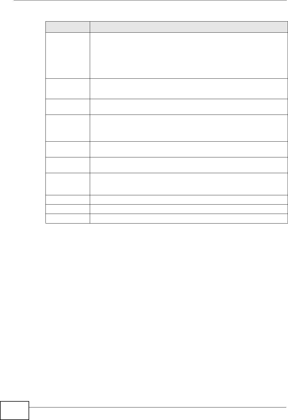
Forward To Select the interface through which traffic that matches the rule is
forwarded out. If you select Unchange, the ZyXEL Device forwards
traffic of this class according to the default routing table.
If traffic of this class comes from a WAN interface and is in a queue that
forwards traffic through the LAN/WLAN interface, the ZyXEL Device
ignores the setting here.
IPP/DS Field Select IPP/TOS to specify an IP precedence range and type of services.
Select DSCP to specify a DiffServ Code Point (DSCP) range.
IP Precedence
Remarking
Enter a range from 0 to 7 to re-assign IP precedence to matched traffic.
Zero is the lowest priority and seven is the highest.
Type of
Service
Remarking
Select a type of service to re-assign the priority level to matched traffic.
Available options are: Normal service, Minimize delay, Maximize
throughput, Maximize reliability and Minimize monetary cost.
DSCP
Remarking
Specify a DSCP number between 0 and 63 to re-assign the priority level
to matched traffic.
802.1p
Remarking
Select a priority level (0 to 7) to re-assign the priority level to matched
traffic.
Queue # Specify a queue tag to matched traffic. Traffic assigned to a higher queue
gets through faster while traffic in lower queues is dropped when there is
network congestion.
Add Click this to add the rule.
Delete Click this to remove the rule.
Cancel Click this to restore previously saved settings.
Table 58 Advanced Setup > QoS > Class Setup
LABEL DESCRIPTION
Chapter 14 Quality of Service (QoS)
P-660HN-Tx User’s Guide 173
14.5.1 IEEE 802.1p
IEEE 802.1p specifies the user priority field and defines up to eight separate traffic
types. The following table describes the traffic types defined in the IEEE 802.1d
standard (which incorporates the 802.1p).
14.5.2 IP Precedence
Similar to IEEE 802.1p prioritization at layer-2, you can use IP precedence to
prioritize packets in a layer-3 network. IP precedence uses three bits of the eight-
bit ToS (Type of Service) field in the IP header. There are eight classes of services
(ranging from zero to seven) in IP precedence. Zero is the lowest priority level and
seven is the highest.
14.5.3 Automatic Priority Queue Assignment
If you enable QoS on the ZyXEL Device, the ZyXEL Device can automatically base
on the IEEE 802.1p priority level, IP precedence and/or packet length to assign
priority to traffic which does not match a class.
The following table shows you the internal layer-2 and layer-3 QoS mapping on
the ZyXEL Device. On the ZyXEL Device, traffic assigned to higher priority queues
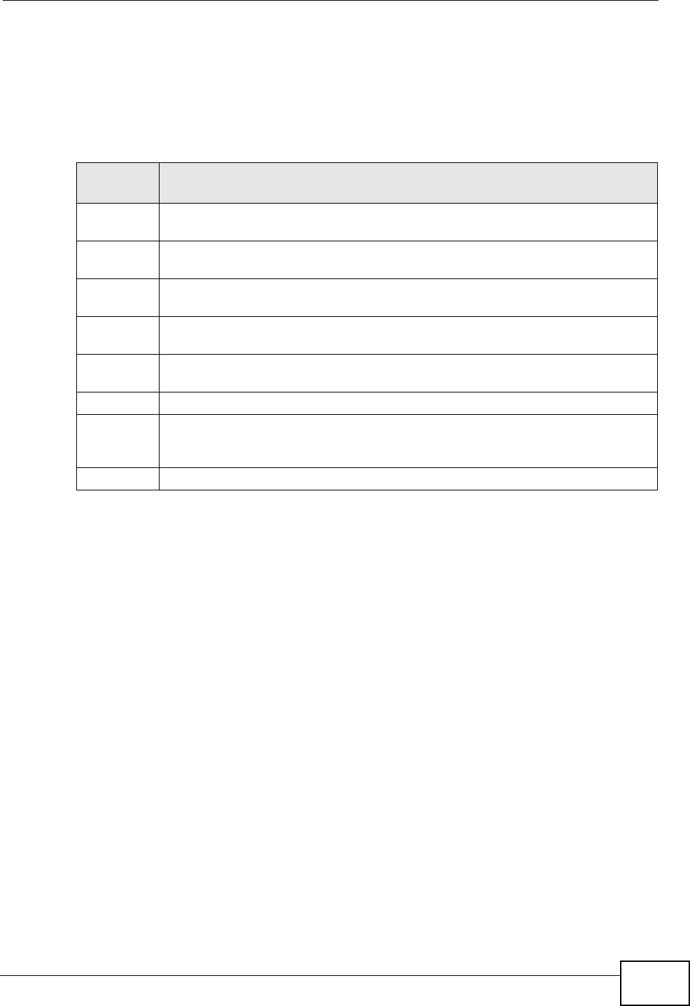
Table 59 IEEE 802.1p Priority Level and Traffic Type
PRIORITY
LEVEL TRAFFIC TYPE
Level 7 Typically used for network control traffic such as router configuration
messages.
Level 6 Typically used for voice traffic that is especially sensitive to jitter (jitter is the
variations in delay).
Level 5 Typically used for video that consumes high bandwidth and is sensitive to
jitter.
Level 4 Typically used for controlled load, latency-sensitive traffic such as SNA
(Systems Network Architecture) transactions.
Level 3 Typically used for “excellent effort” or better than best effort and would
include important business traffic that can tolerate some delay.
Level 2 This is for “spare bandwidth”.
Level 1 This is typically used for non-critical “background” traffic such as bulk
transfers that are allowed but that should not affect other applications and
users.
Level 0 Typically used for best-effort traffic.

Chapter 14 Quality of Service (QoS)
P-660HN-Tx User’s Guide
174
gets through faster while traffic in lower index queues is dropped if the network is
congested.
Table 60 Internal Layer2 and Layer3 QoS Mapping
PRIORITY
QUEUE
LAYER 2 LAYER 3
IEEE 802.1P
USER PRIORITY
(ETHERNET
PRIORITY)
TOS (IP
PRECEDENCE) DSCP IP PACKET
LENGTH (BYTE)
0 1 0 000000
12
2 0 0 000000 >1100
3 3 1 001110
001100
001010
001000
250~1100
4 4 2 010110
010100
010010
010000
5 5 3 011110
011100
011010
011000
<250
6 6 4 100110
100100
100010
100000
5 101110
101000
7 7 6 110000
111000
7

P-660HN-Tx User’s Guide 175
CHAPTER 15
Dynamic DNS Setup
15.1 Overview
Dynamic DNS allows you to update your current dynamic IP address with one or
many dynamic DNS services so that anyone can contact you (in NetMeeting, CU-
SeeMe, etc.). You can also access your FTP server or Web site on your own
computer using a domain name (for instance myhost.dhs.org, where myhost is a
name of your choice) that will never change instead of using an IP address that
changes each time you reconnect. Your friends or relatives will always be able to
call you even if they don't know your IP address.
First of all, you need to have registered a dynamic DNS account with
www.dyndns.org. This is for people with a dynamic IP from their ISP or DHCP
server that would still like to have a domain name. The Dynamic DNS service
provider will give you a password or key.
15.1.1 What You Can Do in the DDNS Screen
Use the Dynamic DNS screen (Section 15.2 on page 176) to enable DDNS and
configure the DDNS settings on the ZyXEL Device.
15.1.2 What You Need To Know About DDNS
DYNDNS Wildcard
Enabling the wildcard feature for your host causes *.yourhost.dyndns.org to be
aliased to the same IP address as yourhost.dyndns.org. This feature is useful if
you want to be able to use, for example, www.yourhost.dyndns.org and still reach
your hostname.
If you have a private WAN IP address, then you cannot use Dynamic DNS.
Chapter 15 Dynamic DNS Setup
P-660HN-Tx User’s Guide
176
15.2 The Dynamic DNS Screen
Use this screen to change your ZyXEL Device’s DDNS. Click Advanced >
Dynamic DNS. The screen appears as shown.
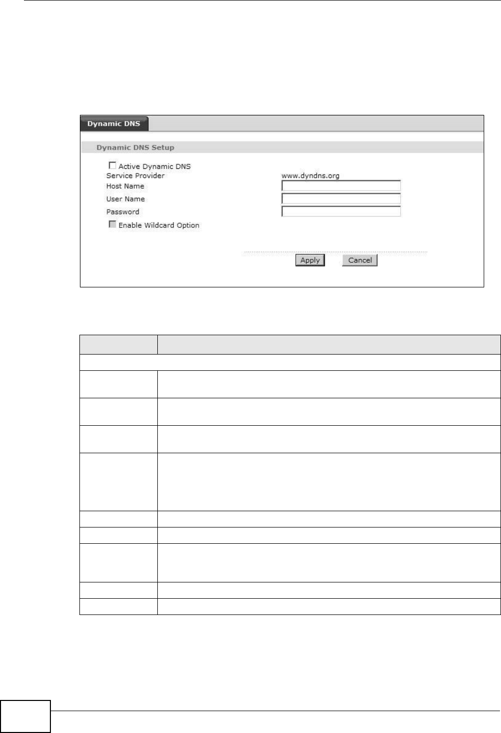
Figure 83 Advanced > Dynamic DNS
The following table describes the fields in this screen.
Table 61 Advanced > Dynamic DNS
LABEL DESCRIPTION
Dynamic DNS Setup
Active
Dynamic DNS
Select this check box to use dynamic DNS.
Service
Provider
This is the name of your Dynamic DNS service provider.
Dynamic DNS
Type
Select the type of service that you are registered for from your Dynamic
DNS service provider.
Host Name Type the domain name assigned to your ZyXEL Device by your Dynamic
DNS provider.
You can specify up to two host names in the field separated by a comma
(",").
User Name Type your user name.
Password Type the password assigned to you.
Enable
Wildcard
Option
Select the check box to enable DynDNS Wildcard.
Apply Click this to save your changes.
Cancel Click this to restore your previously saved settings.
P-660HN-Tx User’s Guide 177
CHAPTER 16
Remote Management
16.1 Overview
Remote management allows you to determine which services/protocols can access
which ZyXEL Device interface (if any) from which computers.
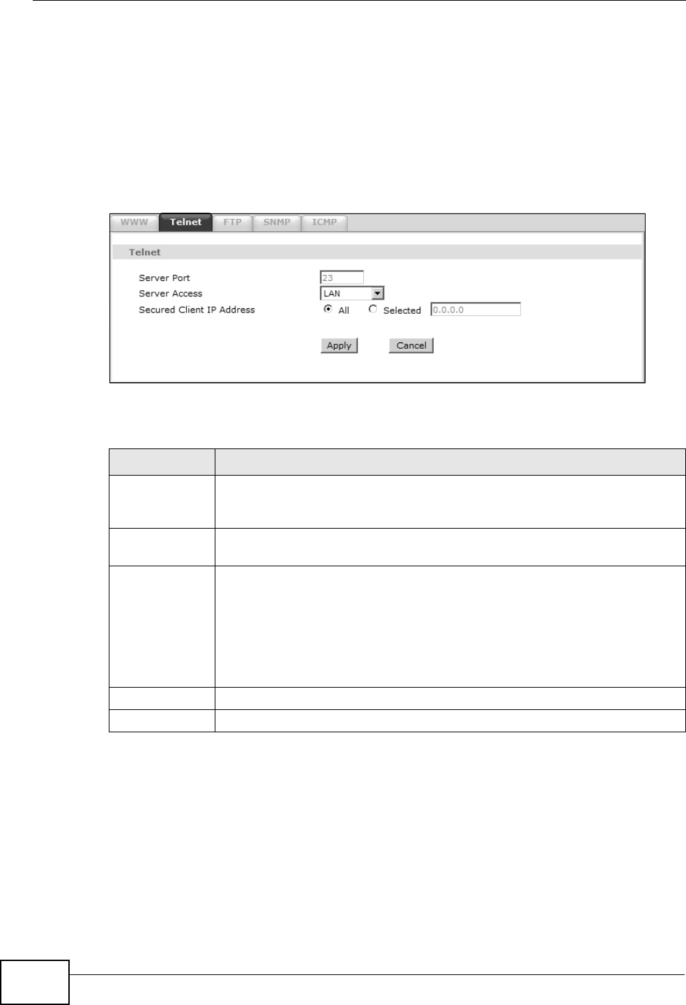
The following figure shows remote management of the ZyXEL Device coming in
from the WAN.
Figure 84 Remote Management From the WAN
Note: When you configure remote management to allow management from the WAN,
you still need to configure a IP filter rule to allow access.
You may manage your ZyXEL Device from a remote location via:
•Internet (WAN only)
•LAN only
•LAN and WAN
• None (Disable)
To disable remote management of a service, select Disable in the corresponding
Service Access field.
LAN WAN
HTTP
Telnet

Chapter 16 Remote Management
P-660HN-Tx User’s Guide
178
16.1.1 What You Can Do in the Remote Management Screens
•Use the WWW screen (Section 16.2 on page 179) to configure through which
interface(s) and from which IP address(es) users can use HTTP to manage the
ZyXEL Device.
•Use the Telnet screen (Section 16.3 on page 180) to configure through which
interface(s) and from which IP address(es) users can use Telnet to manage the
ZyXEL Device.
•Use the FTP screen (Section 16.4 on page 180) to configure through which
interface(s) and from which IP address(es) users can use FTP to access the
ZyXEL Device.
• Your ZyXEL Device can act as an SNMP agent, which allows a manager station to
manage and monitor the ZyXEL Device through the network. Use the SNMP
screen (see Section 16.5 on page 181) to configure through which interface(s)
and from which IP address(es) users can use SNMP to access the ZyXEL Device.
•Use the ICMP screen (Section 16.6 on page 184) to set whether or not your
ZyXEL Device will respond to pings and probes for services that you have not
made available.
16.1.2 What You Need to Know About Remote Management
Remote Management Limitations
Remote management does not work when:
• You have not enabled that service on the interface in the corresponding remote
management screen.
• You have disabled that service in one of the remote management screens.
• The IP address in the Secured Client IP Address field does not match the
client IP address. If it does not match, the ZyXEL Device will disconnect the
session immediately.
• There is a firewall rule that blocks it.
Remote Management and NAT
When NAT is enabled:
• Use the ZyXEL Device’s WAN IP address when configuring from the WAN.
• Use the ZyXEL Device’s LAN IP address when configuring from the LAN.
Chapter 16 Remote Management
P-660HN-Tx User’s Guide 179
16.2 The WWW Screen
Use this screen to specify how to connect to the ZyXEL Device from a web
browser, such as Internet Explorer.
16.2.1 Configuring the WWW Screen
Click Advanced > Remote MGMT to display the WWW screen.
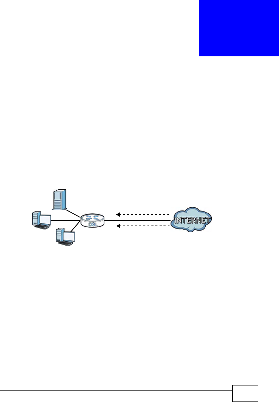
Figure 85 Advanced > Remote MGMT > WWW
The following table describes the labels in this screen.
Table 62 Advanced > Remote Management > WWW
LABEL DESCRIPTION
Server Port You may change the server port number for a service, if needed.
However, you must use the same port number in order to use that
service for remote management.
Server Access Select the interface(s) through which a computer may access the ZyXEL
Device using this service.
Secured Client
IP Address
A secured client is a “trusted” computer that is allowed to communicate
with the ZyXEL Device using this service.
Select All to allow any computer to access the ZyXEL Device using this
service.
Choose Selected to just allow the computer with the IP address that
you specify to access the ZyXEL Device using this service.
Apply Click this to save your changes.
Cancel Click this to restore your previously saved settings.
Chapter 16 Remote Management
P-660HN-Tx User’s Guide
180
16.3 The Telnet Screen
You can use Telnet to access the ZyXEL Device’s command line interface. Specify
which interfaces allow Telnet access and from which IP address the access can
come.
Click Advanced > Remote MGMT > Telnet tab to display the screen as shown.
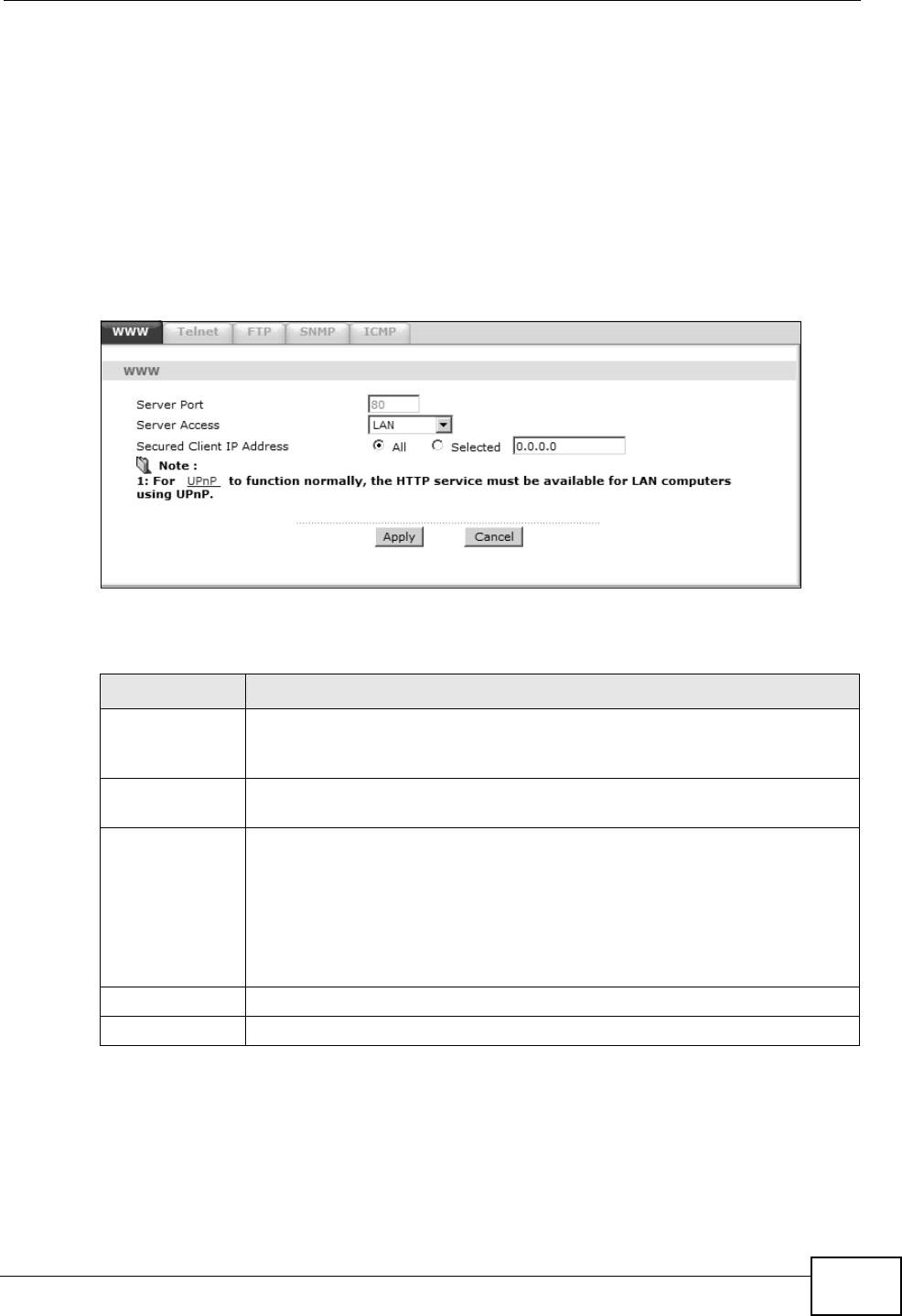
Figure 86 Advanced > Remote MGMT > Telnet
The following table describes the labels in this screen.
16.4 The FTP Screen
You can use FTP (File Transfer Protocol) to upload and download the ZyXEL
Device’s firmware and configuration files. Please see the User’s Guide chapter on
firmware and configuration file maintenance for details. To use this feature, your
computer must have an FTP client.
Table 63 Advanced > Remote Management > Telnet
LABEL DESCRIPTION
Server Port You may change the server port number for a service if needed, however
you must use the same port number in order to use that service for
remote management.
Server Access Select the interface(s) through which a computer may access the ZyXEL
Device using this service.
Secured Client
IP Address
A secured client is a “trusted” computer that is allowed to communicate
with the ZyXEL Device using this service.
Select All to allow any computer to access the ZyXEL Device using this
service.
Choose Selected to just allow the computer with the IP address that you
specify to access the ZyXEL Device using this service.
Apply Click this to save your changes.
Cancel Click this to restore your previously saved settings.
Chapter 16 Remote Management
P-660HN-Tx User’s Guide 181
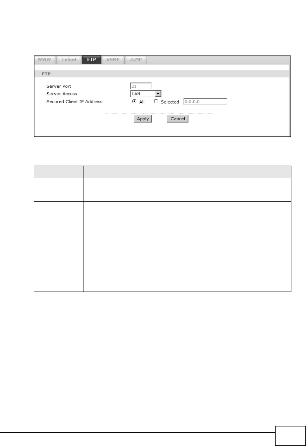
Use this screen to specify which interfaces allow FTP access and from which IP
address the access can come. To change your ZyXEL Device’s FTP settings, click
Advanced > Remote MGMT > FTP. The screen appears as shown.
Figure 87 Advanced > Remote MGMT > FTP
The following table describes the labels in this screen.
16.5 The SNMP Screen
Simple Network Management Protocol is a protocol used for exchanging
management information between network devices. Your ZyXEL Device supports
SNMP agent functionality, which allows a manager station to manage and monitor
the ZyXEL Device through the network. The ZyXEL Device supports SNMP version
Table 64 Advanced > Remote MGMT > FTP
LABEL DESCRIPTION
Server Port You may change the server port number for a service, if needed.
However, you must use the same port number in order to use that
service for remote management.
Server Access Select the interface(s) through which a computer may access the ZyXEL
Device using this service.
Secured Client
IP Address
A secured client is a “trusted” computer that is allowed to communicate
with the ZyXEL Device using this service.
Select All to allow any computer to access the ZyXEL Device using this
service.
Choose Selected to just allow the computer with the IP address that
you specify to access the ZyXEL Device using this service.
Apply Click this to save your changes.
Cancel Click this to restore your previously saved settings.
Chapter 16 Remote Management
P-660HN-Tx User’s Guide
182
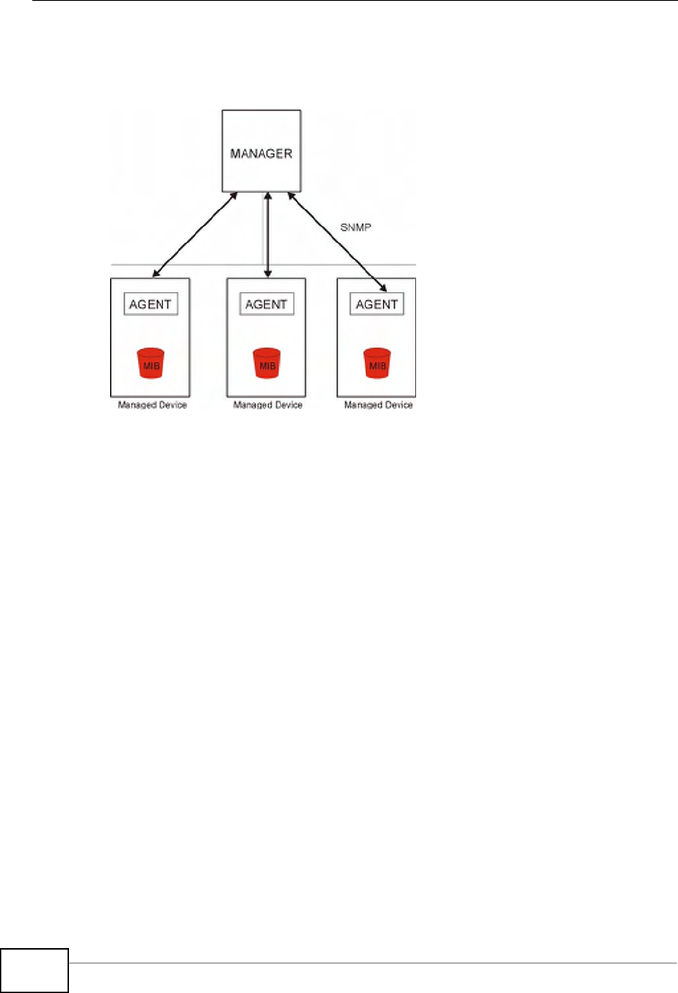
one (SNMPv1) and version two (SNMPv2c). The next figure illustrates an SNMP
management operation.
Figure 88 SNMP Management Model
An SNMP managed network consists of two main types of component: agents and
a manager.
An agent is a management software module that resides in a managed device (the
ZyXEL Device). An agent translates the local management information from the
managed device into a form compatible with SNMP. The manager is the console
through which network administrators perform network management functions. It
executes applications that control and monitor managed devices.
The managed devices contain object variables/managed objects that define each
piece of information to be collected about a device. Examples of variables include
such as number of packets received, node port status etc. A Management
Information Base (MIB) is a collection of managed objects. SNMP allows a
manager and agents to communicate for the purpose of accessing these objects.
Chapter 16 Remote Management
P-660HN-Tx User’s Guide 183
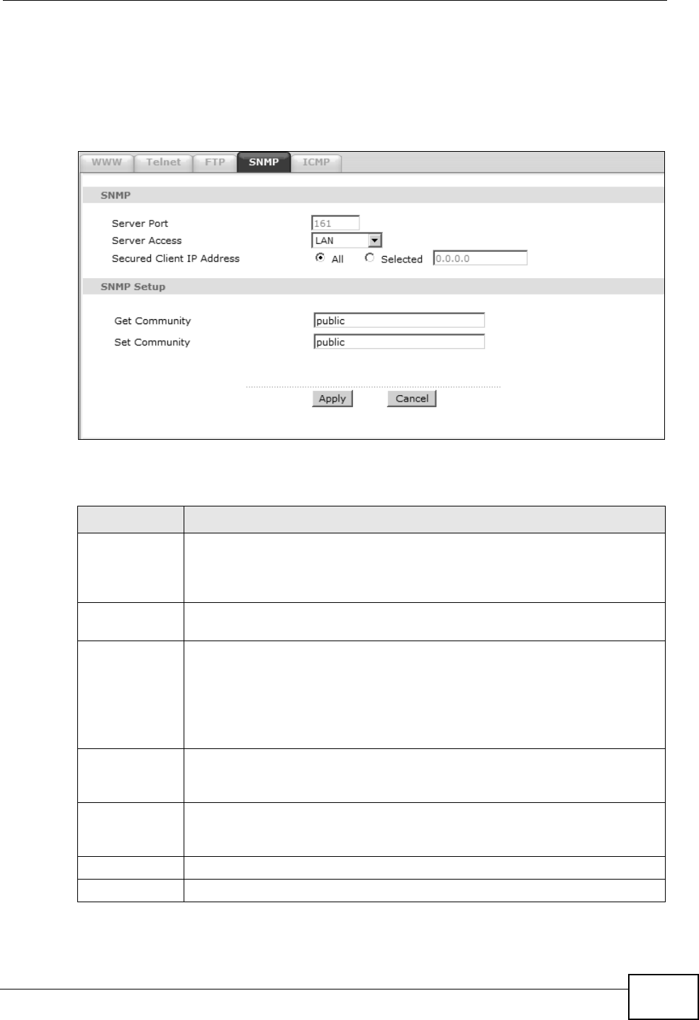
16.5.1 Configuring SNMP
To change your ZyXEL Device’s SNMP settings, click Advanced > Remote MGMT
> SNMP tab. The screen appears as shown.
Figure 89 Advanced > Remote MGMT > SNMP
The following table describes the labels in this screen.
Table 65 Advanced > Remote MGMT > SNMP
LABEL DESCRIPTION
Server Port The SNMP agent listens on port 161 by default. If you change the SNMP
server port to a different number on the ZyXEL Device, for example
8161, then you must notify people who need to access the ZyXEL Device
SNMP agent to use the same port.
Server Access Select the interface(s) through which a computer may access the ZyXEL
Device using this service.
Secured Client
IP Address
A secured client is a “trusted” computer that is allowed to access the
SNMP agent on the ZyXEL Device.
Select All to allow any computer to access the SNMP agent.
Choose Selected to just allow the computer with the IP address that you
specify to access the SNMP agent.
Get
Community
Enter the Get Community, which is the password for the incoming Get
and GetNext requests from the management station. The default is
public and allows all requests.
Set
Community
Enter the Set community, which is the password for incoming Set
requests from the management station. The default is public and allows
all requests.
Apply Click Apply to save your changes back to the ZyXEL Device.
Cancel Click Cancel to begin configuring this screen afresh.
Chapter 16 Remote Management
P-660HN-Tx User’s Guide
184
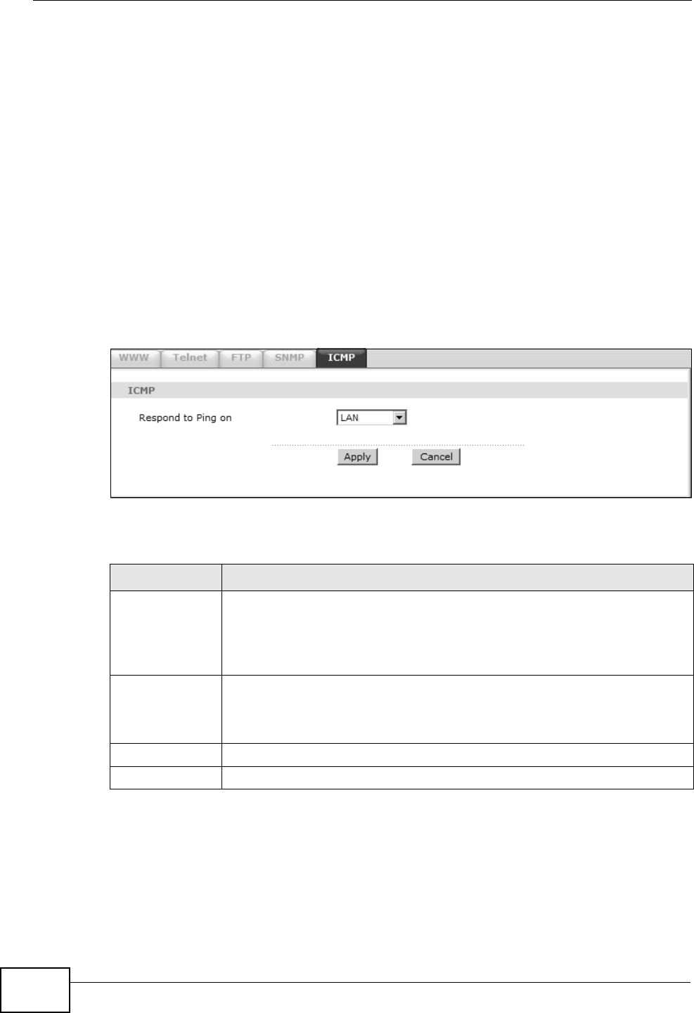
16.6 The ICMP Screen
To change your ZyXEL Device’s security settings, click Advanced > Remote
MGMT > ICMP. The screen appears as shown.
If an outside user attempts to probe an unsupported port on your ZyXEL Device,
an ICMP response packet is automatically returned. This allows the outside user to
know the ZyXEL Device exists. Your ZyXEL Device supports anti-probing, which
prevents the ICMP response packet from being sent. This keeps outsiders from
discovering your ZyXEL Device when unsupported ports are probed.
Note: If you want your device to respond to pings and requests for unauthorized
services, you will also need to configure the firewall accordingly by disabling
SPI.
Figure 90 Advanced > Remote Management > ICMP
The following table describes the labels in this screen.
Table 66 Advanced > Remote Management > ICMP
LABEL DESCRIPTION
ICMP Internet Control Message Protocol is a message control and error-
reporting protocol between a host server and a gateway to the Internet.
ICMP uses Internet Protocol (IP) datagrams, but the messages are
processed by the TCP/IP software and directly apparent to the
application user.
Respond to
Ping on
The ZyXEL Device will not respond to any incoming Ping requests when
Disable is selected. Select LAN to reply to incoming LAN Ping requests.
Select WAN to reply to incoming WAN Ping requests. Otherwise select
LAN & WAN to reply to both incoming LAN and WAN Ping requests.
Apply Click this to save your changes.
Cancel Click this to restore your previously saved settings.

Chapter 17 Universal Plug-and-Play (UPnP)
P-660HN-Tx User’s Guide 185
CHAPTER 17
Universal Plug-and-Play (UPnP)
17.1 Overview
Universal Plug and Play (UPnP) is a distributed, open networking standard that
uses TCP/IP for simple peer-to-peer network connectivity between devices. A
UPnP device can dynamically join a network, obtain an IP address, convey its
capabilities and learn about other devices on the network. In turn, a device can
leave a network smoothly and automatically when it is no longer in use.
17.1.1 What You Can Do in the UPnP Screen
Use the UPnP screen (Section 17.2 on page 187) to enable UPnP on the ZyXEL
Device and allow UPnP-enabled applications to automatically configure the ZyXEL
Device.
17.1.2 What You Need to Know About UPnP
Identifying UPnP Devices
UPnP hardware is identified as an icon in the Network Connections folder
(Windows XP). Each UPnP compatible device installed on your network will appear
as a separate icon. Selecting the icon of a UPnP device will allow you to access the
information and properties of that device.
NAT Traversal
UPnP NAT traversal automates the process of allowing an application to operate
through NAT. UPnP network devices can automatically configure network
addressing, announce their presence in the network to other UPnP devices and
enable exchange of simple product and service descriptions. NAT traversal allows
the following:
• Dynamic port mapping
• Learning public IP addresses

Chapter 17 Universal Plug-and-Play (UPnP)
P-660HN-Tx User’s Guide
186
•Assigning lease times to mappings
Windows Messenger is an example of an application that supports NAT traversal
and UPnP.
See the NAT chapter for more information on NAT.
Cautions with UPnP
The automated nature of NAT traversal applications in establishing their own
services and opening firewall ports may present network security issues. Network
information and configuration may also be obtained and modified by users in some
network environments.
When a UPnP device joins a network, it announces its presence with a multicast
message. For security reasons, the ZyXEL Device allows multicast messages on
the LAN only.
All UPnP-enabled devices may communicate freely with each other without
additional configuration. Disable UPnP if this is not your intention.
UPnP and ZyXEL
ZyXEL has achieved UPnP certification from the Universal Plug and Play Forum
UPnP™ Implementers Corp. (UIC). ZyXEL's UPnP implementation supports
Internet Gateway Device (IGD) 1.0.
See the following sections for examples of installing and using UPnP.
P-660HN-Tx User’s Guide 187
17.2 The UPnP Screen
Use the following screen to configure the UPnP settings on your ZyXEL Device.
Click Advanced > UPnP to display the screen shown next.
See Section 17.1 on page 185 for more information.
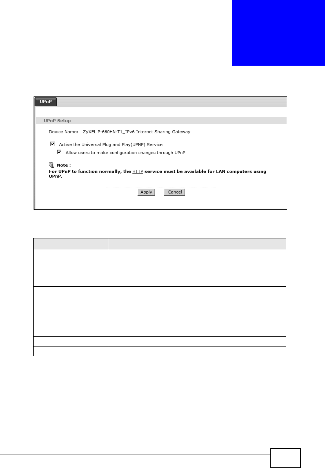
Figure 91 Advanced > UPnP > General
The following table describes the fields in this screen.
Table 67 Advanced > UPnP > General
LABEL DESCRIPTION
Active the Universal Plug
and Play (UPnP) Feature
Select this check box to activate UPnP. Be aware that anyone
could use a UPnP application to open the web configurator's
login screen without entering the ZyXEL Device's IP address
(although you must still enter the password to access the web
configurator).
Allow users to make
configuration changes
through UPnP
Select this check box to allow UPnP-enabled applications to
automatically configure the ZyXEL Device so that they can
communicate through the ZyXEL Device, for example by using
NAT traversal, UPnP applications automatically reserve a NAT
forwarding port in order to communicate with another UPnP
enabled device; this eliminates the need to manually configure
port forwarding for the UPnP enabled application.
Apply Click this to save your changes.
Cancel Click this to restore your previously saved settings.
Chapter 17 Universal Plug-and-Play (UPnP)
P-660HN-Tx User’s Guide
188
17.3 Installing UPnP in Windows Example
This section shows how to install UPnP in Windows Me and Windows XP.
Installing UPnP in Windows Me
Follow the steps below to install the UPnP in Windows Me.
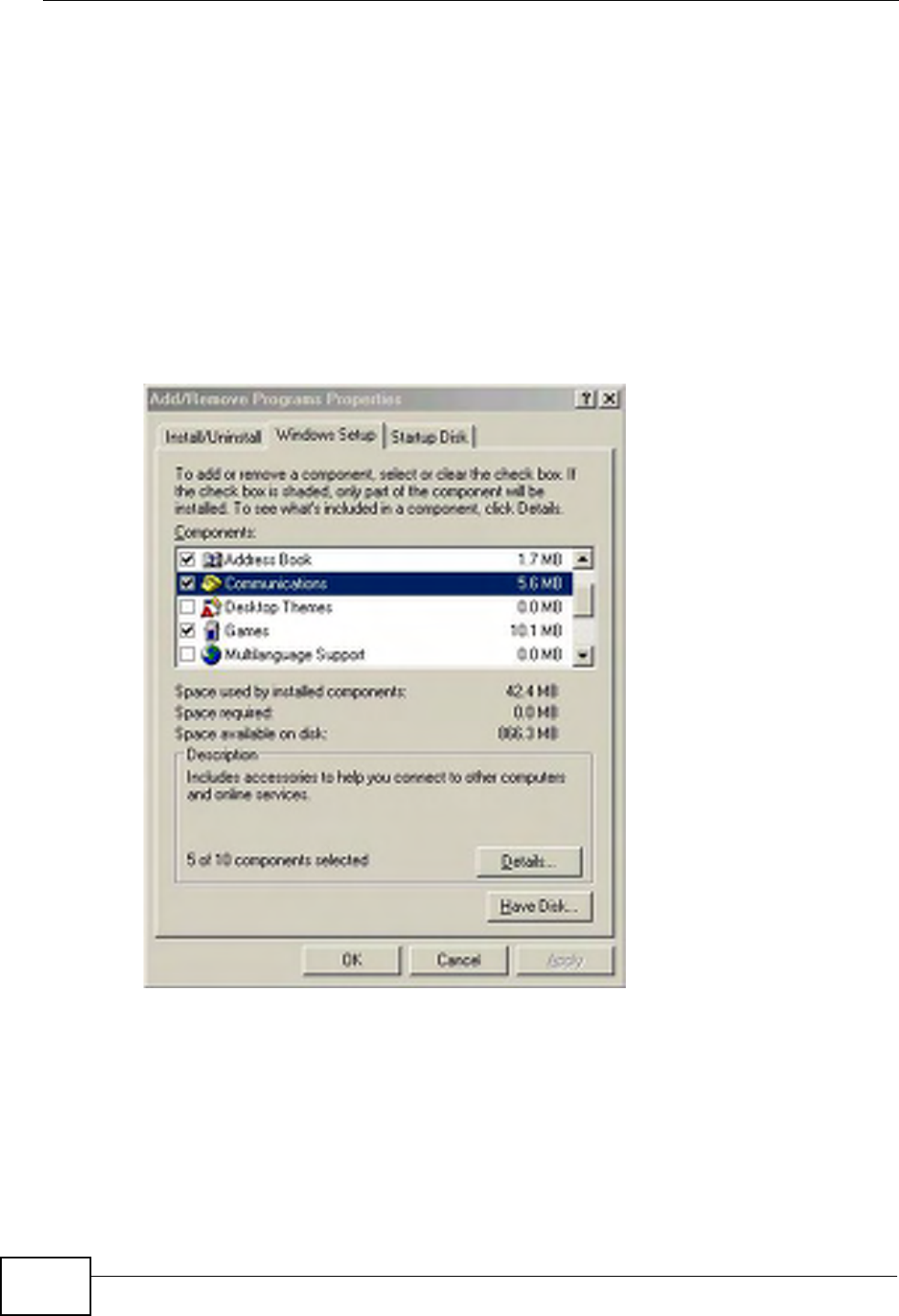
1Click Start and Control Panel. Double-click Add/Remove Programs.
2Click on the Windows Setup tab and select Communication in the
Components selection box. Click Details.
Add/Remove Programs: Windows Setup: Communication
Chapter 17 Universal Plug-and-Play (UPnP)
P-660HN-Tx User’s Guide 189
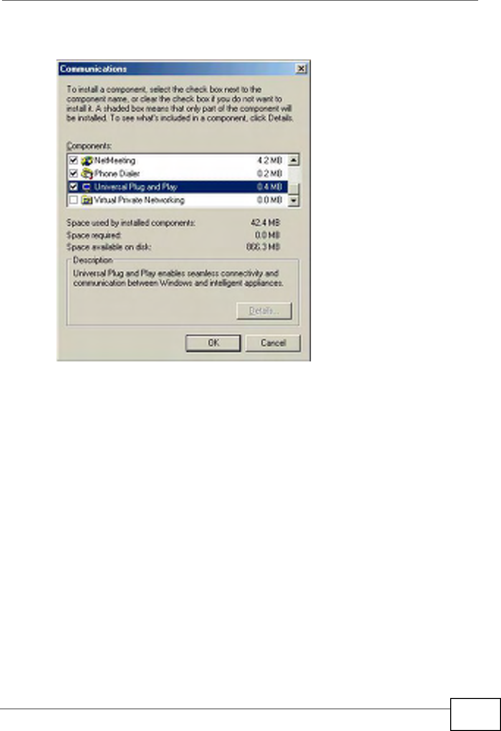
3In the Communications window, select the Universal Plug and Play check box
in the Components selection box.
Add/Remove Programs: Windows Setup: Communication: Components
4Click OK to go back to the Add/Remove Programs Properties window and click
Next.
5Restart the computer when prompted.
Installing UPnP in Windows XP
Follow the steps below to install the UPnP in Windows XP.
1Click Start and Control Panel.
2Double-click Network Connections.
Chapter 17 Universal Plug-and-Play (UPnP)
P-660HN-Tx User’s Guide
190
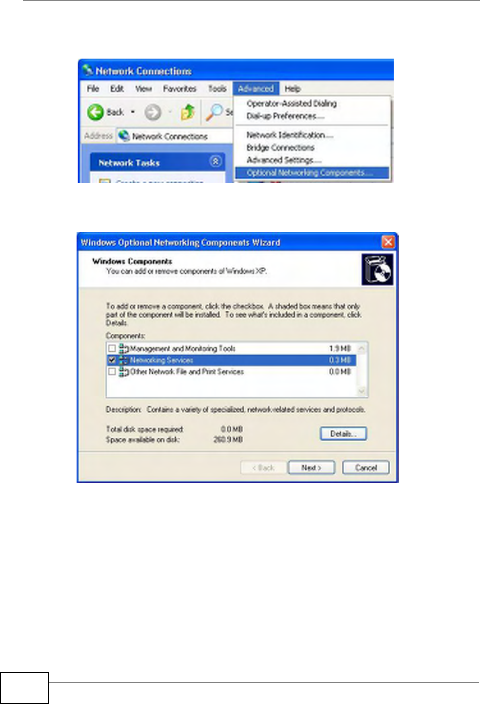
3In the Network Connections window, click Advanced in the main menu and
select Optional Networking Components ….
Network Co nnections
4The Windows Optional Networking Components Wizard window displays.
Select Networking Service in the Components selection box and click Details.
Windows Optional Networking Components Wizard
Chapter 17 Universal Plug-and-Play (UPnP)
P-660HN-Tx User’s Guide 191
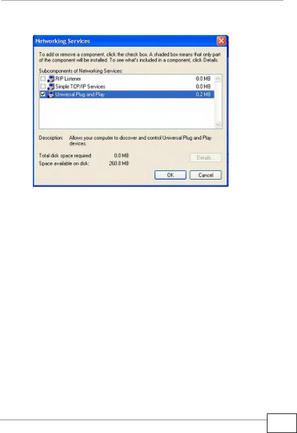
5In the Networking Services window, select the Universal Plug and Play check
box.
Networking Services
6Click OK to go back to the Windows Optional Networking Component Wizard
window and click Next.
17.4 Using UPnP in Windows XP Example
This section shows you how to use the UPnP feature in Windows XP. You must
already have UPnP installed in Windows XP and UPnP activated on the ZyXEL
Device.
Make sure the computer is connected to a LAN port of the ZyXEL Device. Turn on
your computer and the ZyXEL Device.
Auto-discover Your UPnP-enabled Network Device
1Click Start and Control Panel. Double-click Network Connections. An icon
displays under Internet Gateway.
Chapter 17 Universal Plug-and-Play (UPnP)
P-660HN-Tx User’s Guide
192
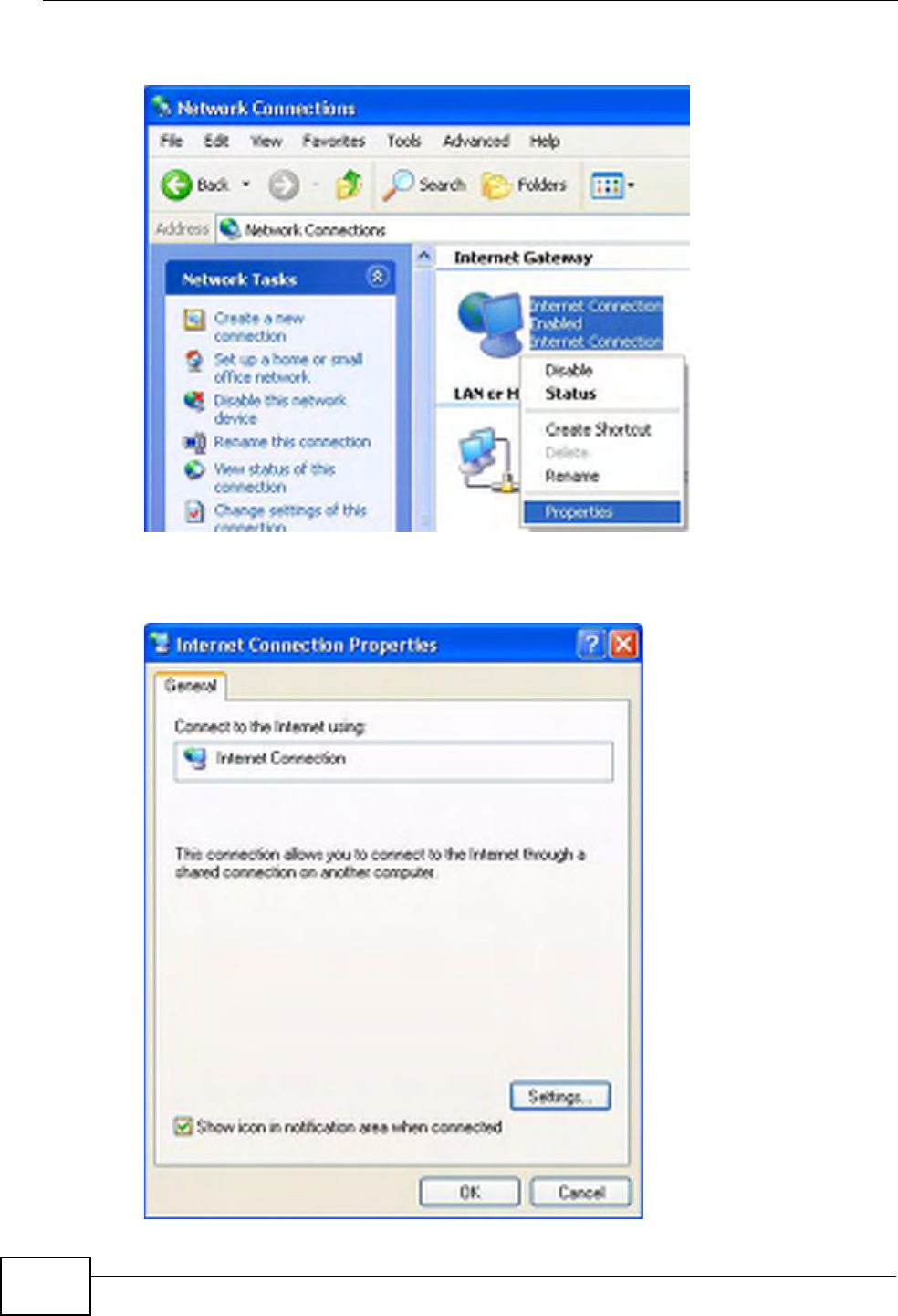
2Right-click the icon and select Properties.
Network Co nnections
3In the Internet Connection Properties window, click Settings to see the port
mappings there were automatically created.
Internet Connec tion Properties
Chapter 17 Universal Plug-and-Play (UPnP)
P-660HN-Tx User’s Guide 193
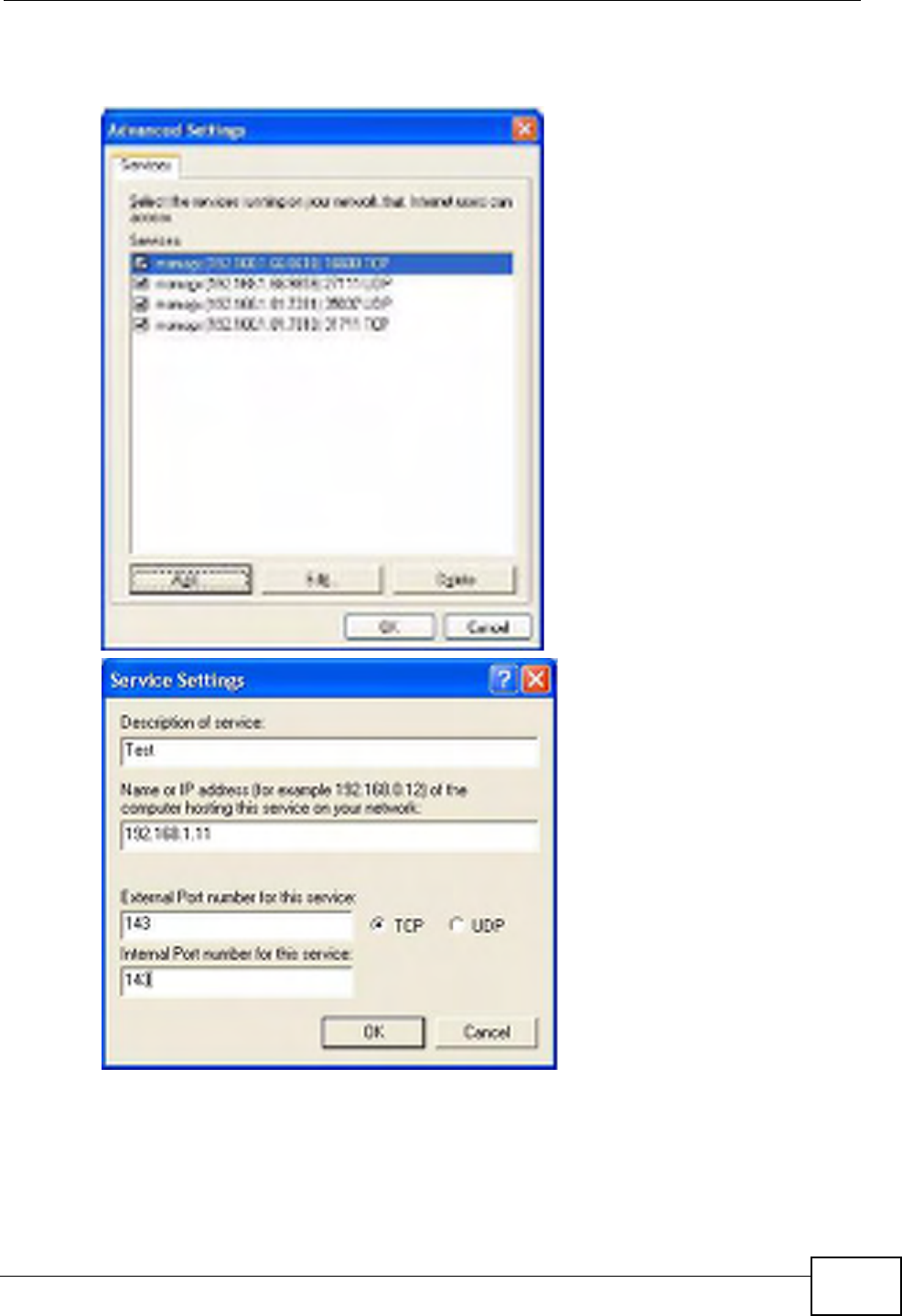
4You may edit or delete the port mappings or click Add to manually add port
mappings.
Internet Connec tion Properties : Advanced Settin gs
Internet Connec tion Properties : Advanced Settin gs: Add
5When the UPnP-enabled device is disconnected from your computer, all port
mappings will be deleted automatically.
Chapter 17 Universal Plug-and-Play (UPnP)
P-660HN-Tx User’s Guide
194
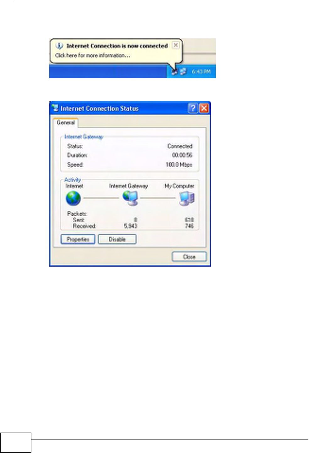
6Select Show icon in notification area when connected option and click OK.
An icon displays in the system tray.
System Tray Icon
7Double-click on the icon to display your current Internet connection status.
Internet Conn ection Status
Web Configurator Easy Access
With UPnP, you can access the web-based configurator on the ZyXEL Device
without finding out the IP address of the ZyXEL Device first. This comes helpful if
you do not know the IP address of the ZyXEL Device.
Follow the steps below to access the web configurator.
1Click Start and then Control Panel.
2Double-click Network Connections.
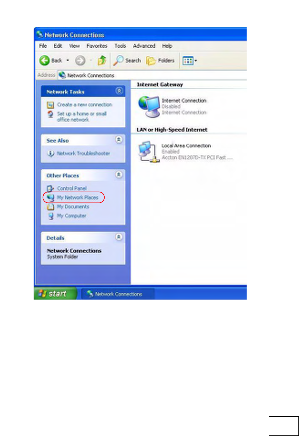
Chapter 17 Universal Plug-and-Play (UPnP)
P-660HN-Tx User’s Guide 195
3Select My Network Places under Other Places.
Network Co nnections
4An icon with the description for each UPnP-enabled device displays under Local
Network.
Chapter 17 Universal Plug-and-Play (UPnP)
P-660HN-Tx User’s Guide
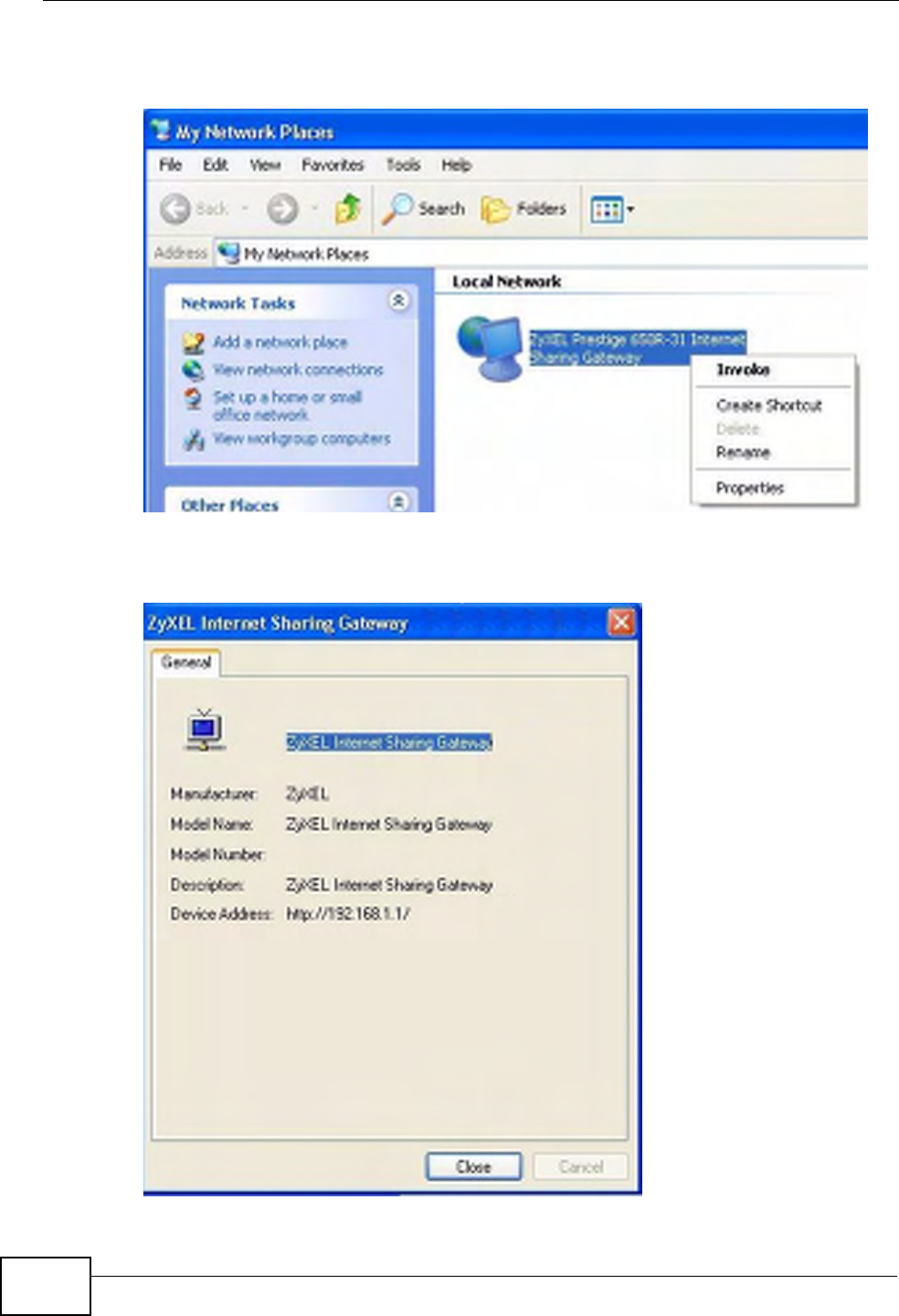
196
5Right-click on the icon for your ZyXEL Device and select Invoke. The web
configurator login screen displays.
Network Co nnections: My Netw ork Places
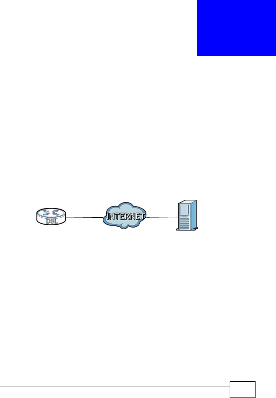
6Right-click on the icon for your ZyXEL Device and select Properties. A properties
window displays with basic information about the ZyXEL Device.
Network Co nnections: My Netw ork Places: Proper ties: Example
P-660HN-Tx User’s Guide 197
CHAPTER 18
CWMP
18.1 Overview
The ZyXEL Device supports TR-069 Amendment 1 (CPE WAN Management
Protocol Release 2.0) and TR-069 Amendment 2 (CPE WAN Management Protocol
v1.1, Release 3.0).
TR-069 is a protocol that defines how your ZyXEL Device (ZD) can be managed
via a management server (MS) such as ZyXEL’s Vantage Access.
Figure 92 LAN and WAN
An administrator can use a management server to remotely set up the ZyXEL
device, modify settings, perform firmware upgrades as well as monitor and
diagnose the ZyXEL device.
In order to use CWMP, you need to configure the following steps:
1Activate CWMP
2Specify the URL, username and password.
3Activate periodic inform and specify an interval value.
MSZD
Chapter 18 CWMP
P-660HN-Tx User’s Guide
198
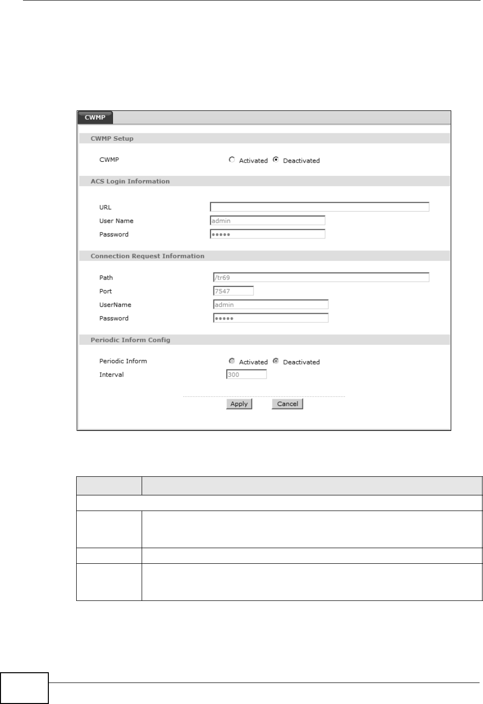
18.2 The CWMP Setup Screen
Use this screen to configure your ZyXEL Device to be managed by a management
server. Click Advanced> CWMP to display the following screen.
Figure 93 Advanced > CWMP
The following table describes the fields in this screen.
Table 68 Advanced > CWMP
LINK DESCRIPTION
CWMP Setup
CWMP Select Activated to allow the ZyXEL Device to be managed by a
management server or select Deactivated to not allow the ZyXEL Device
to be managed by a management server.
Login ACS Configure this part of the screen to log into the management server.
URL Type the IP address or domain name of the management server. If the
ZyXEL Device is behind a NAT router that assigns it a private IP address,
you will have to configure a NAT port forwarding rule on the NAT router.

Chapter 18 CWMP
P-660HN-Tx User’s Guide 199
User Name The user name is used to authenticate the ZyXEL Device when making a
connection to the management server. This user name on the management
server and the ZyXEL Device must be the same. Type a user name of up to
255 printable characters found on an English-language keyboard. Spaces
and characters such as @#$%^&*()_+ are allowed.
Password The password is used to authenticate the ZyXEL Device when making a
connection to the management server. This password on the management
server and the ZyXEL Device must be the same. Type a password of up to
255 printable characters found on an English-language keyboard.
Connection
Request
Use this part of the screen to allow the management server to connect to
the ZyXEL Device after a successful login.
Path Type the IP address or domain name of the ZyXEL Device. The
management server uses this path to verify the ZyXEL Device.
Port The default port for access to the ZyXEL Device from the management
server is port 7547. If you change it, make sure it does not conflict with
another port on your network and it is recommended to use a port number
above 1024 (not a commonly used port). The management server should
use this port to connect to the ZyXEL Device. You may need to alter your
NAT port forwarding rules if they were already configured.
UserName The user name is used to authenticate the management server when
connecting to the ZyXEL Device. Type a user name of up to 255 printable
characters found on an English-language keyboard. Spaces and characters
such as @#$%^&*()_+ are allowed.
Password The password is used to authenticate the management server when
connecting to the ZyXEL Device. Type a password of up to 255 printable
characters found on an English-language keyboard. Spaces are not
allowed.
Periodic
Inform
Select Activated to have the ZyXEL Device periodically send information to
the management server (recommended if CWMP is enabled) or select
Deactivated to not have the ZyXEL Device periodically send information to
the management server
Interval The interval is the duration in seconds for which the ZyXEL Device must
attempt to connect with the management server to send information and
check for configuration updates. Enter a value between 1 and 86400
seconds.
Apply Click this to save your changes.
Cancel Click this to restore your previously saved settings.
Table 68 Advanced > CWMP (continued)
LINK DESCRIPTION

Chapter 18 CWMP
P-660HN-Tx User’s Guide
200
P-660HN-Tx User’s Guide 201
CHAPTER 19
System Settings
19.1 Overview
This chapter shows you how to configure system related settings, such as system
time, password, name, the domain name and the inactivity timeout interval.
19.1.1 What You Can Do in the System Settings Screens
•Use the General screen (Section 19.2 on page 201) to configure system
settings.
•Use the Time Setting screen (Section 19.3 on page 202) to set the system
time.
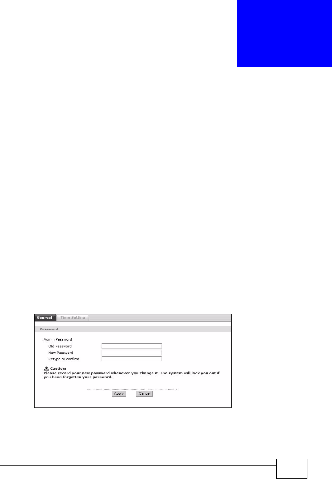
19.2 The General Screen
Use this screen to configure system admin password.
Click Maintenance > System to open the General screen.
Figure 94 Maintenance > System > General
Chapter 19 System Settings
P-660HN-Tx User’s Guide
202
The following table describes the labels in this screen.
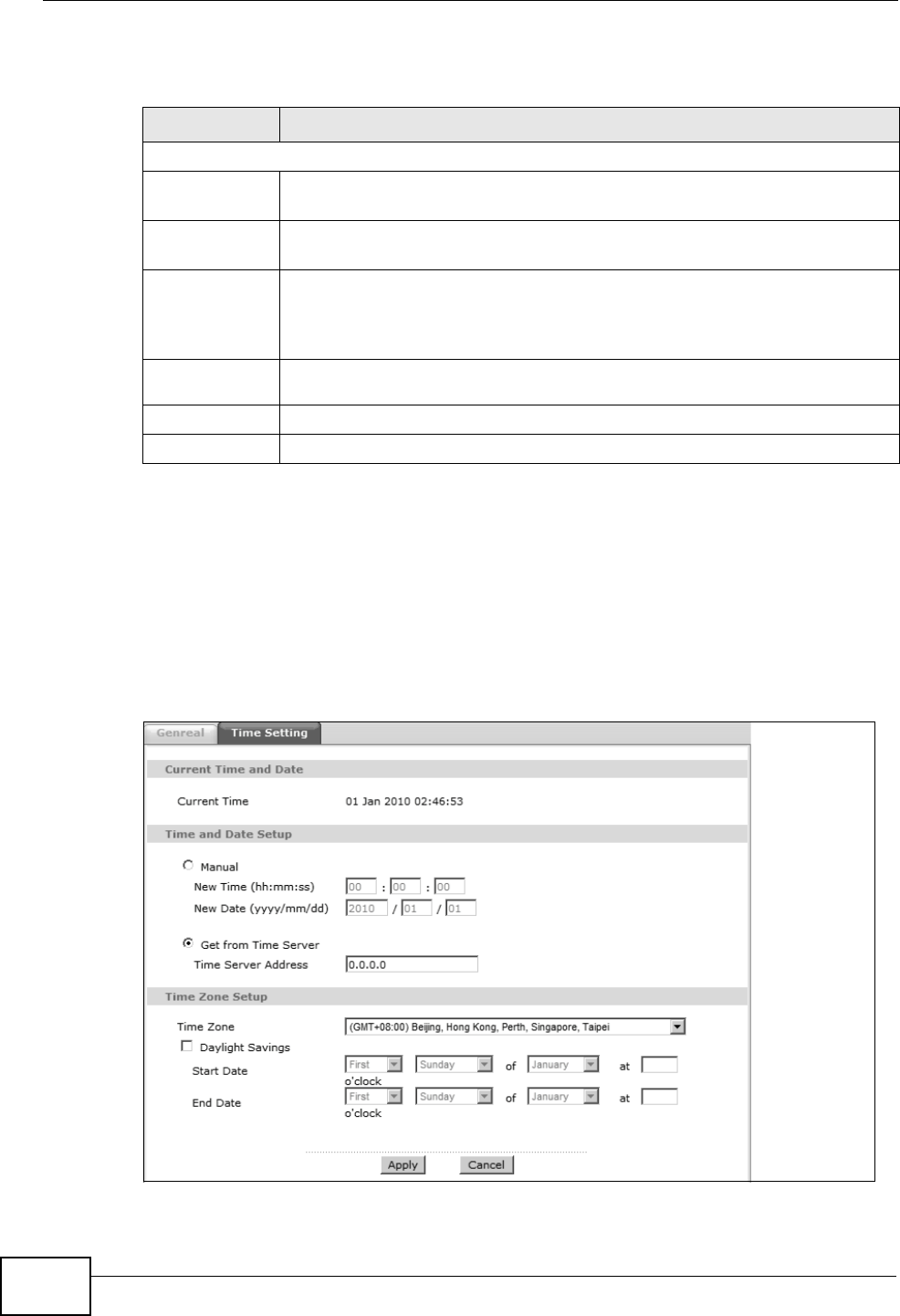
19.3 The Time Setting Screen
Use this screen to configure the ZyXEL Device’s time based on your local time
zone. To change your ZyXEL Device’s time and date, click Maintenance >
System > Time Setting. The screen appears as shown.
Figure 95 Maintenance > System > Time Setting
Table 69 Maintenance > System > General
LABEL DESCRIPTION
Password
Admin
Password
Old
Password Type the default password or the existing password you use to access the
system in this field.
New
Password Type your new system password (up to 30 characters). Note that as you
type a password, the screen displays a (*) for each character you type.
After you change the password, use the new password to access the
ZyXEL Device.
Retype to
confirm Type the new password again for confirmation.
Apply Click this to save your changes.
Cancel Click this to restore your previously saved settings.

Chapter 19 System Settings
P-660HN-Tx User’s Guide 203
The following table describes the fields in this screen.
Table 70 Maintenance > System > Time Setting
LABEL DESCRIPTION
Current Time and Date
Current Time This field displays the time and date of your ZyXEL Device.
Each time you reload this page, the ZyXEL Device synchronizes the
time and date with the time server.
Time and Date Setup
Manual Select this radio button to enter the time and date manually. If you
configure a new time and date, Time Zone and Daylight Saving at the
same time, the new time and date you entered has priority and the
Time Zone and Daylight Saving settings do not affect it.
New Time
(hh:mm:ss)
This field displays the last updated time from the time server or the last
time configured manually.
When you set Time and Date Setup to Manual, enter the new time in
this field and then click Apply.
New Date
(yyyy/mm/dd)
This field displays the last updated date from the time server or the last
date configured manually.
When you set Time and Date Setup to Manual, enter the new date in
this field and then click Apply.
Get from Time
Server
Select this radio button to have the ZyXEL Device get the time and date
from the time server you specified below.
Time Server
Address
Enter the IP address or URL (up to 20 extended ASCII characters in
length) of your time server. Check with your ISP/network administrator
if you are unsure of this information.
Time Zone Setup
Time Zone Choose the time zone of your location. This will set the time difference
between your time zone and Greenwich Mean Time (GMT).
Daylight
Savings
Daylight saving is a period from late spring to early fall when many
countries set their clocks ahead of normal local time by one hour to
give more daytime light in the evening.
Select this option if you use Daylight Saving Time.
Start Date Configure the day and time when Daylight Saving Time starts if you
selected Enable Daylight Saving. The o'clock field uses the 24 hour
format. Here are a couple of examples:
Daylight Saving Time starts in most parts of the United States on the
second Sunday of March. Each time zone in the United States starts
using Daylight Saving Time at 2 A.M. local time. So in the United States
you would select Second, Sunday, March and type 2 in the o'clock
field.
Daylight Saving Time starts in the European Union on the last Sunday
of March. All of the time zones in the European Union start using
Daylight Saving Time at the same moment (1 A.M. GMT or UTC). So in
the European Union you would select Last, Sunday, March. The time
you type in the o'clock field depends on your time zone. In Germany
for instance, you would type 2 because Germany's time zone is one
hour ahead of GMT or UTC (GMT+1).

Chapter 19 System Settings
P-660HN-Tx User’s Guide
204
End Date Configure the day and time when Daylight Saving Time ends if you
selected Enable Daylight Saving. The o'clock field uses the 24 hour
format. Here are a couple of examples:
Daylight Saving Time ends in the United States on the first Sunday of
November. Each time zone in the United States stops using Daylight
Saving Time at 2 A.M. local time. So in the United States you would
select First, Sunday, November and type 2 in the o'clock field.
Daylight Saving Time ends in the European Union on the last Sunday of
October. All of the time zones in the European Union stop using
Daylight Saving Time at the same moment (1 A.M. GMT or UTC). So in
the European Union you would select Last, Sunday, October. The
time you type in the o'clock field depends on your time zone. In
Germany for instance, you would type 2 because Germany's time zone
is one hour ahead of GMT or UTC (GMT+1).
Apply Click this to save your changes.
Cancel Click this to restore your previously saved settings.
Table 70 Maintenance > System > Time Setting (continued)
LABEL DESCRIPTION

P-660HN-Tx User’s Guide 205
CHAPTER 20
Logs
20.1 Overview
This chapter contains information about viewing the ZyXEL Device’s logs.
The web configurator allows you to choose which types of events and/or alerts to
have the ZyXEL Device log and then display the logs.
20.1.1 What You Need To Know About Logs
Alerts
An alert is a message that is enabled as soon as the event occurs. They include
system errors, attacks (access control) and attempted access to blocked web
sites. Some categories such as System Errors consist of both logs and alerts. You
may differentiate them by their color in the View Log screen. Alerts display in red
and logs display in black.
Logs
A log is a message about an event that occurred on your ZyXEL Device. For
example, when someone logs in to the ZyXEL Device, you can set a schedule for
how often logs should be enabled, or sent to a syslog server.
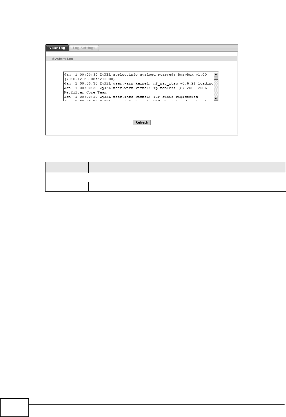
20.2 The View Log Screen
Use the View Log screen to view logs.
Chapter 20 Logs
P-660HN-Tx User’s Guide
206
To view your ZyXEL Device’s logs, click Maintenance > Logs > View Log. The
screen appears as shown.
Figure 96 Maintenance > System Logs
The following table describes the fields in this screen.
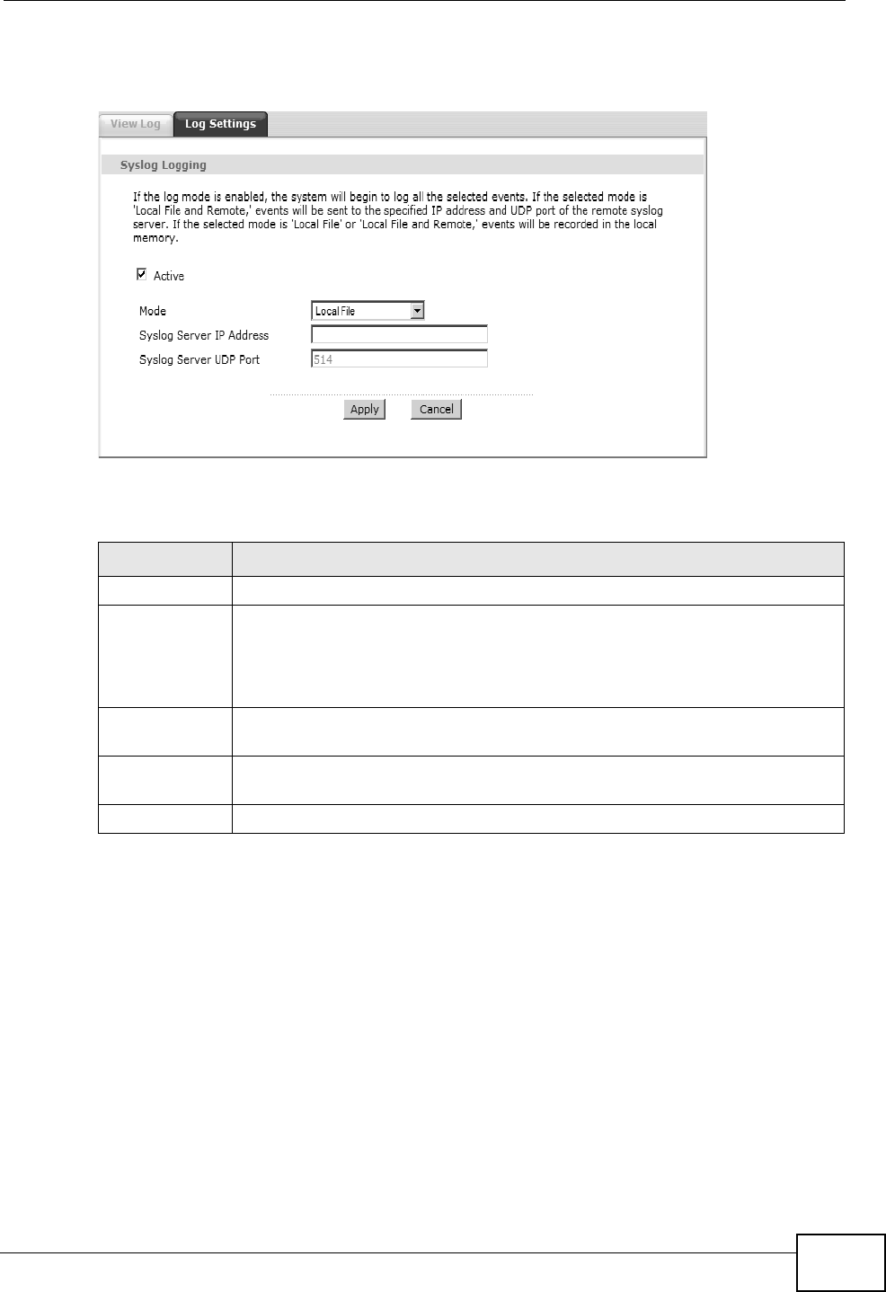
20.3 The Log Settings Screen
Use the Log Settings screen to configure to where the ZyXEL Device is to send
logs and which logs and/or immediate alerts the ZyXEL Device is to record and
display.
To change your ZyXEL Device’s log settings, click Maintenance > Logs > Log
Settings. The screen appears as shown.
Maintenance > Logs > Log Settings
LABEL DESCRIPTION
System Log
Refresh Click this to refresh to log display.
Chapter 20 Logs
P-660HN-Tx User’s Guide 207
Figure 97 Maintenance > System Logs > Log Settings
The following table describes the fields in this screen.
Table 71 Maintenance > Logs > Log Settings
LABEL DESCRIPTION
Active Select to enable or disable system logging.
Mode Select Local File to record the logs and store them in the local memory
of the ZyXEL Device only.
Select Local File and Remote to record the logs and store them in the
local memory and also send logs to the log server.
Syslog Server
IP Address
Enter the server name or the IP address of the log server.
Syslog Server
UDP Port
Enter the UDP port of the log server.
Apply Click Apply to save your customized settings.

Chapter 20 Logs
P-660HN-Tx User’s Guide
208

P-660HN-Tx User’s Guide 209
CHAPTER 21
Tools
21.1 Overview
This chapter explains how to upload new firmware, manage configuration files and
restart your ZyXEL Device.
Use the instructions in this chapter to change the device’s configuration file or
upgrade its firmware. After you configure your device, you can backup the
configuration file to a computer. That way if you later misconfigure the device, you
can upload the backed up configuration file to return to your previous settings.
You can alternately upload the factory default configuration file if you want to
return the device to the original default settings. The firmware determines the
device’s available features and functionality. You can download new firmware
releases from your nearest ZyXEL FTP site (or www.zyxel.com) to use to upgrade
your device’s performance.
Only use firmware for your device’s specific model. Refer to the
label on the bottom of your ZyXEL Device.
21.1.1 What You Can Do in the Tool Screens
•Use the Firmware Upgrade screen (Section 21.2 on page 209) to upload
firmware to your device.
•Use the Configuration screen (Section 21.3 on page 212) to backup and
restore device configurations. You can also reset your device settings back to
the factory default.
•Use the Restart screen (Section 21.4 on page 215) to restart your ZyXEL
device.
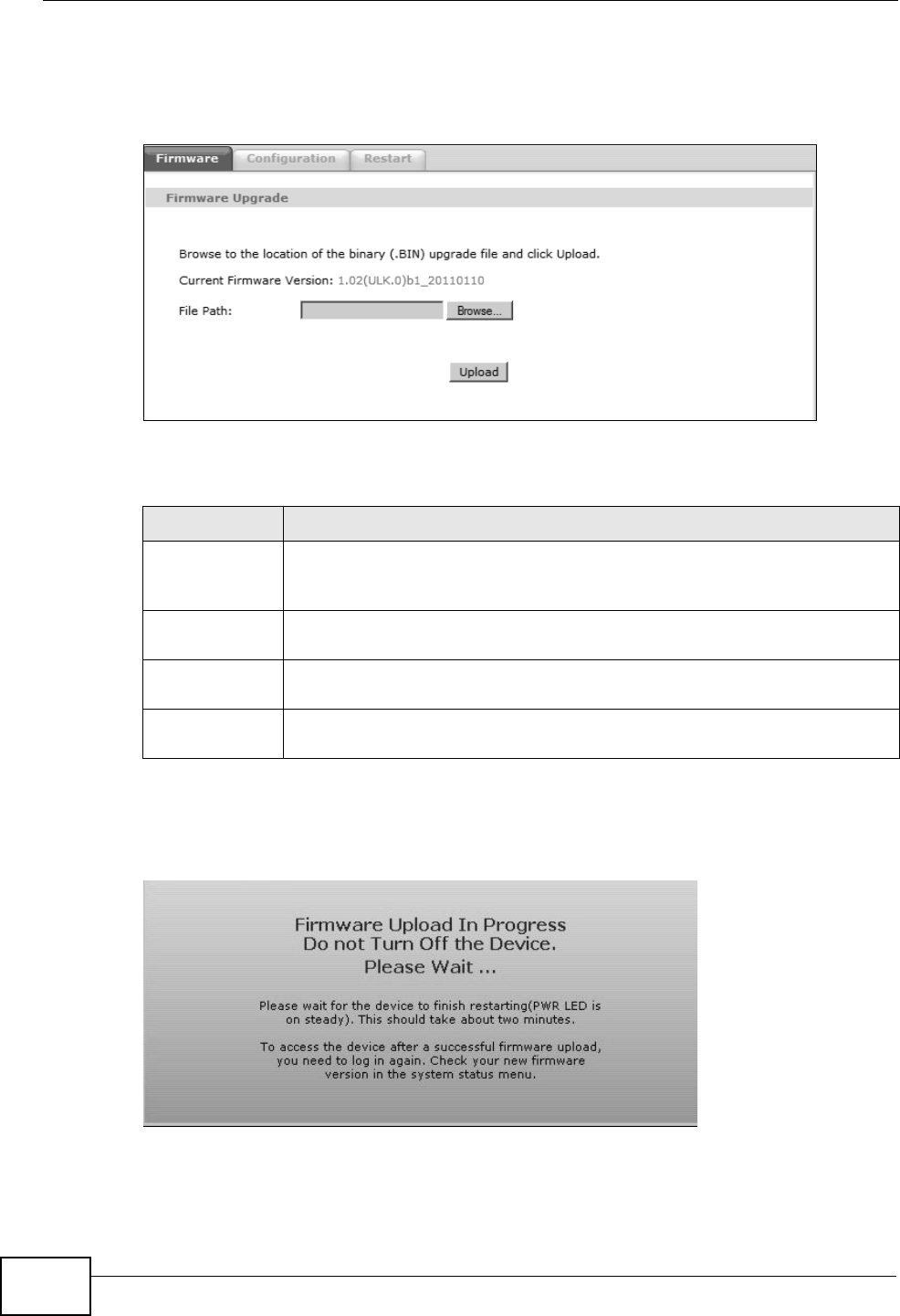
21.2 The Firmware Screen
Click Maintenance > Tools to open the Firmware screen. Follow the
instructions in this screen to upload firmware to your ZyXEL Device. The upload
process uses HTTP (Hypertext Transfer Protocol) and may take up to two minutes.
After a successful upload, the system will reboot.
Chapter 21 Tools
P-660HN-Tx User’s Guide
210
Do NOT turn off the ZyXEL Device while firmware upload is in
progress!
Figure 98 Maintenance > Tools > Firmware
The following table describes the labels in this screen.
After you see the Firmware Upload in Progress screen, wait two minutes
before logging into the ZyXEL Device again.
Figure 99 Firmware Upload In Progress
Table 72 Maintenance > Tools > Firmware
LABEL DESCRIPTION
Current
Firmware
Version
This is the present Firmware version and the date created.
File Path Type in the location of the file you want to upload in this field or click
Browse ... to find it.
Browse... Click this to find the .bin file you want to upload. Remember that you
must decompress compressed (.zip) files before you can upload them.
Upload Click this to begin the upload process. This process may take up to two
minutes.
Chapter 21 Tools
P-660HN-Tx User’s Guide 211
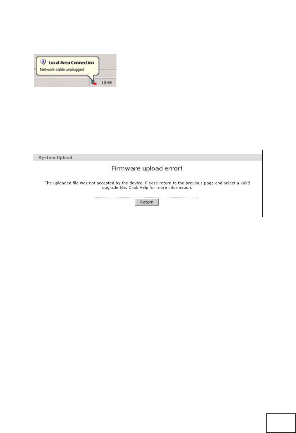
The ZyXEL Device automatically restarts in this time causing a temporary network
disconnect. In some operating systems, you may see the following icon on your
desktop.
Figure 100 Network Temporarily Disconnected
After two minutes, log in again and check your new firmware version in the
Status screen.
If the upload was not successful, the following screen will appear. Click Return to
go back to the Firmware screen.
Figure 101 Error Message
Chapter 21 Tools
P-660HN-Tx User’s Guide
212
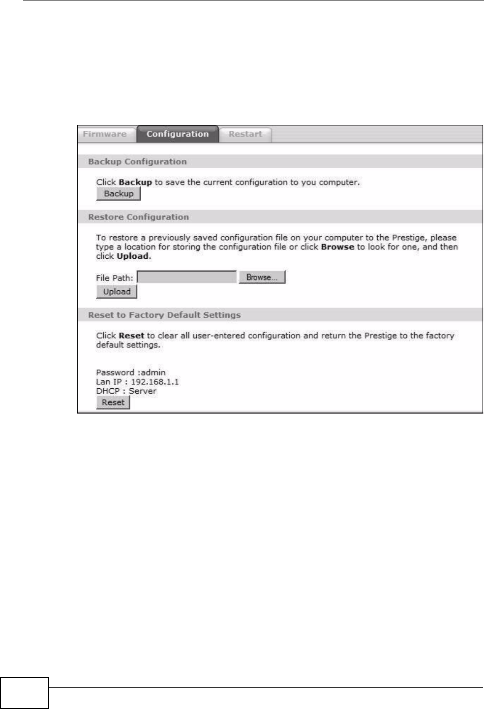
21.3 The Configuration Screen
Click Maintenance > Tools > Configuration. Information related to factory
defaults, backup configuration, and restoring configuration appears in this screen,
as shown next.
Figure 102 Maintenance > Tools > Configuration
Backup Configuration
Backup Configuration allows you to back up (save) the ZyXEL Device’s current
configuration to a file on your computer. Once your ZyXEL Device is configured
and functioning properly, it is highly recommended that you back up your
configuration file before making configuration changes. The backup configuration
file will be useful in case you need to return to your previous settings.
Click Backup to save the ZyXEL Device’s current configuration to your computer.
Chapter 21 Tools
P-660HN-Tx User’s Guide 213
Restore Configuration
Restore Configuration allows you to upload a new or previously saved
configuration file from your computer to your ZyXEL Device.
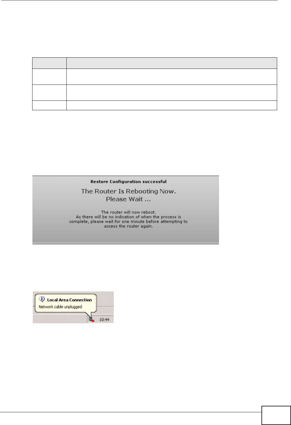
Do not turn off the ZyXEL Device while configuration file upload is
in progress.
After you see a “restore configuration successful” screen, you must then wait one
minute before logging into the ZyXEL Device again.
Figure 103 Configuration Upload Successful
The ZyXEL Device automatically restarts in this time causing a temporary network
disconnect. In some operating systems, you may see the following icon on your
desktop.
Figure 104 Network Temporarily Disconnected
If you uploaded the default configuration file you may need to change the IP
address of your computer to be in the same subnet as that of the default device IP
address (192.168.1.1). See Appendix A on page 235 for details on how to set up
your computer’s IP address.
Table 73 Restore Configuration
LABEL DESCRIPTION
File Path Type in the location of the file you want to upload in this field or click
Browse ... to find it.
Browse... Click this to find the file you want to upload. Remember that you must
decompress compressed (.ZIP) files before you can upload them.
Upload Click this to begin the upload process.
Chapter 21 Tools
P-660HN-Tx User’s Guide
214
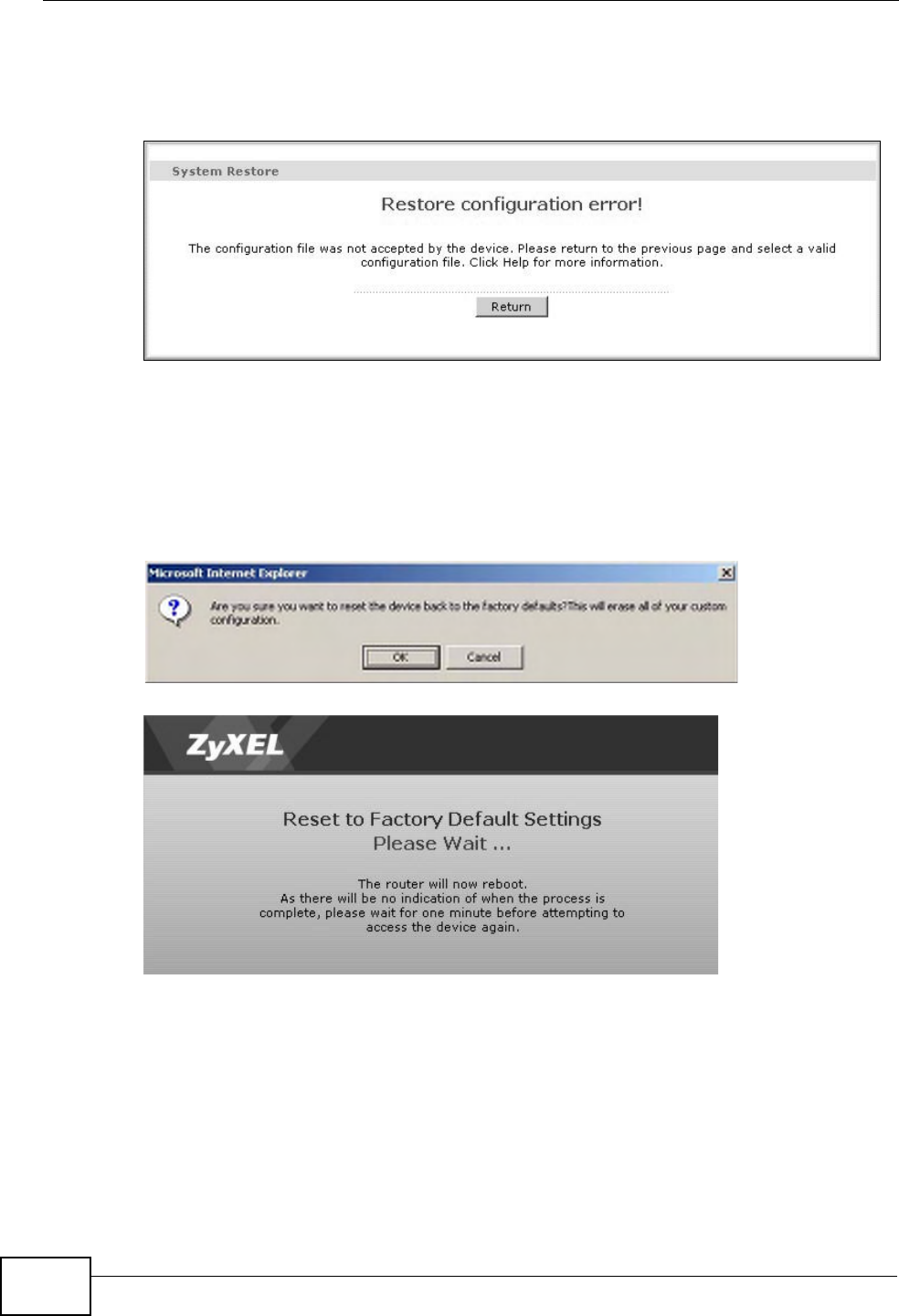
If the upload was not successful, the following screen will appear. Click Return to
go back to the Configuration screen.
Figure 105 Configuration Upload Error
Reset to Factory Defaults
Click the Reset button to clear all user-entered configuration information and
return the ZyXEL Device to its factory defaults. The following warning screen
appears.
Figure 106 Reset Warning Message
Figure 107 Reset In Process Message
You can also press the RESET button on the rear panel to reset the factory
defaults of your ZyXEL Device. Refer to Section 1.7 on page 27 for more
information on the RESET button.
Chapter 21 Tools
P-660HN-Tx User’s Guide 215
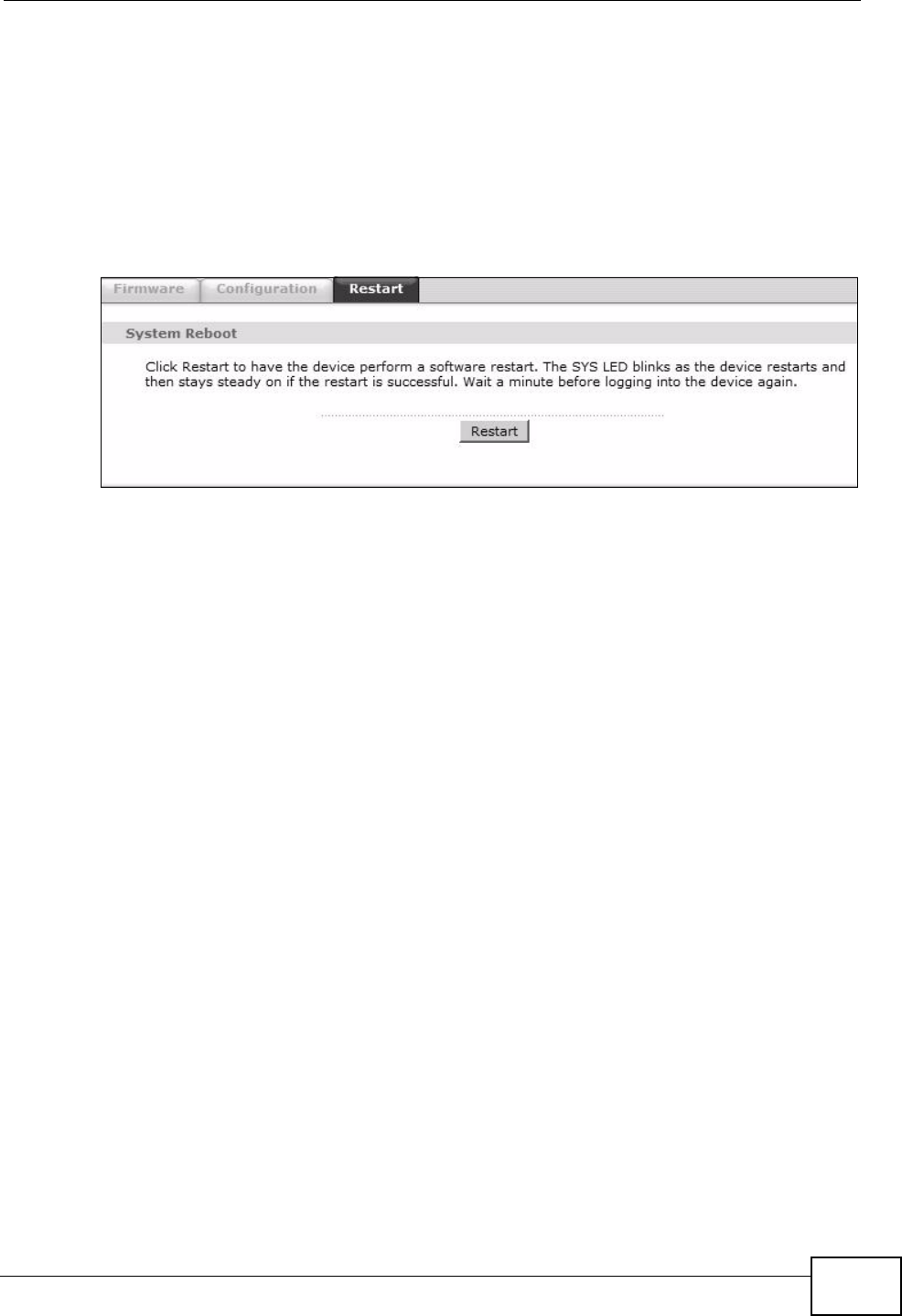
21.4 The Restart Screen
System restart allows you to reboot the ZyXEL Device remotely without turning
the power off. You may need to do this if the ZyXEL Device hangs, for example.
Click Maintenance > Tools > Restart. Click Restart to have the ZyXEL Device
reboot. This does not affect the ZyXEL Device's configuration.
Figure 108 Maintenance > Tools >Restart

Chapter 21 Tools
P-660HN-Tx User’s Guide
216
P-660HN-Tx User’s Guide 217
CHAPTER 22
Diagnostic
22.1 Overview
These read-only screens display information to help you identify problems with the
ZyXEL Device.
22.1.1 What You Can Do in the Diagnostic Screens
•Use the General screen (Section 22.2 on page 217) to ping an IP address.
•Use the DSL Line screen (Section 22.3 on page 218) to view the DSL line
statistics and reset the ADSL line.
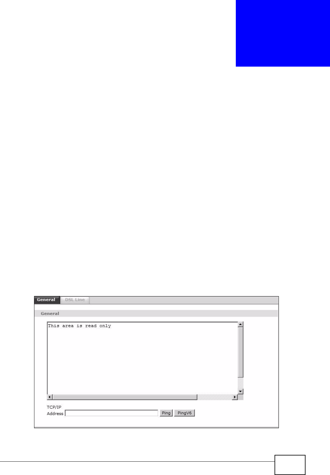
22.2 The General Screen
Use this screen to ping an IP address. Click Maintenance > Diagnostic to open
the screen shown next.
Figure 109 Maintenance > Diagnostic > General
Chapter 22 Diagnostic
P-660HN-Tx User’s Guide
218
The following table describes the fields in this screen.
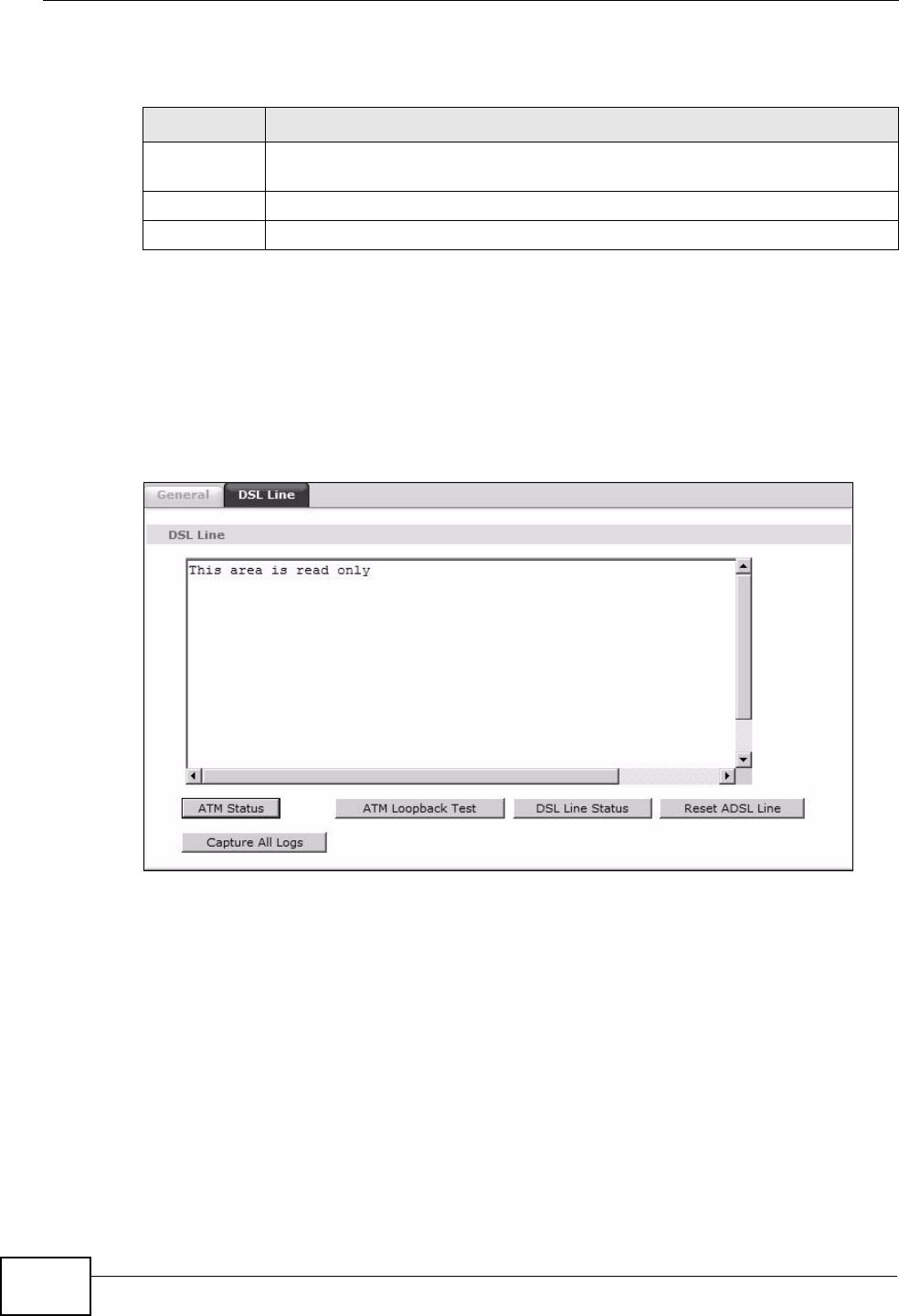
22.3 The DSL Line Screen
Use this screen to view the DSL line statistics and reset the ADSL line. Click
Maintenance > Diagnostic > DSL Line to open the screen shown next.
Figure 110 Maintenance > Diagnostic > DSL Line
Table 74 Maintenance > Diagnostic > General
LABEL DESCRIPTION
TCP/IP
Address
Type the IP address of a computer that you want to ping in order to test a
connection.
Ping Click this to ping the IP address that you entered.
PingV6 Click this to ping the IPv6 address that you entered.

Chapter 22 Diagnostic
P-660HN-Tx User’s Guide 219
The following table describes the fields in this screen.
Table 75 Maintenance > Diagnostic > DSL Line
LABEL DESCRIPTION
ATM Status Click this to view your DSL connection’s Asynchronous Transfer Mode
(ATM) statistics. ATM is a networking technology that provides high-
speed data transfer. ATM uses fixed-size packets of information called
cells. With ATM, a high QoS (Quality of Service) can be guaranteed.
The (Segmentation and Reassembly) SAR driver translates packets into
ATM cells. It also receives ATM cells and reassembles them into packets.
These counters are set back to zero whenever the device starts up.
inPkts is the number of good ATM cells that have been received.
inDiscards is the number of received ATM cells that were rejected.
outPkts is the number of ATM cells that have been sent.
outDiscards is the number of ATM cells sent that were rejected.
inF4Pkts is the number of ATM Operations, Administration, and
Management (OAM) F4 cells that have been received. See ITU
recommendation I.610 for more on OAM for ATM.
outF4Pkts is the number of ATM OAM F4 cells that have been sent.
inF5Pkts is the number of ATM OAM F5 cells that have been received.
outF5Pkts is the number of ATM OAM F5 cells that have been sent.
openChan is the number of times that the ZyXEL Device has opened a
logical DSL channel.
closeChan is the number of times that the ZyXEL Device has closed a
logical DSL channel.
txRate is the number of bytes transmitted per second.
rxRate is the number of bytes received per second.
ATM Loopback
Test
Click this to start the ATM loopback test. Make sure you have configured
at least one PVC with proper VPIs/VCIs before you begin this test. The
ZyXEL Device sends an OAM F5 packet to the DSLAM/ATM switch and
then returns it (loops it back) to the ZyXEL Device. The ATM loopback
test is useful for troubleshooting problems with the DSLAM and ATM
network.

Chapter 22 Diagnostic
P-660HN-Tx User’s Guide
220
DSL Line
Status
Click this to view statistics about the DSL connections.
noise margin downstream is the signal to noise ratio for the
downstream part of the connection (coming into the ZyXEL Device from
the ISP). It is measured in decibels. The higher the number the more
signal and less noise there is.
output power upstream is the amount of power (in decibels) that the
ZyXEL Device is using to transmit to the ISP.
attenuation downstream is the reduction in amplitude (in decibels) of
the DSL signal coming into the ZyXEL Device from the ISP.
Discrete Multi-Tone (DMT) modulation divides up a line’s bandwidth into
sub-carriers (sub-channels) of 4.3125 KHz each called tones. The rest of
the display is the line’s bit allocation. This is displayed as the number (in
hexadecimal format) of bits transmitted for each tone. This can be used
to determine the quality of the connection, whether a given sub-carrier
loop has sufficient margins to support certain ADSL transmission rates,
and possibly to determine whether particular specific types of
interference or line attenuation exist. Refer to the ITU-T G.992.1
recommendation for more information on DMT.
The better (or shorter) the line, the higher the number of bits transmitted
for a DMT tone. The maximum number of bits that can be transmitted per
DMT tone is 15. There will be some tones without any bits as there has to
be space between the upstream and downstream channels.
Reset ADSL
Line
Click this to reinitialize the ADSL line. The large text box above then
displays the progress and results of this operation, for example:
"Start to reset ADSL
Loading ADSL modem F/W...
Reset ADSL Line Successfully!"
Capture All
Logs
Click this to display information and statistics about your ZyXEL Device’s
ATM statistics, DSL connection statistics, DHCP settings, firmware
version, WAN and gateway IP address, VPI/VCI and LAN IP address.
Table 75 Maintenance > Diagnostic > DSL Line (continued)
LABEL DESCRIPTION

P-660HN-Tx User’s Guide 221
CHAPTER 23
Troubleshooting
This chapter offers some suggestions to solve problems you might encounter. The
potential problems are divided into the following categories.
•Power, Hardware Connections, and LEDs
•ZyXEL Device Access and Login
•Internet Access
23.1 Power, Hardware Connections, and LEDs
The ZyXEL Device does not turn on. None of the LEDs turn on.
1Make sure the ZyXEL Device is turned on.
2Make sure you are using the power adaptor or cord included with the ZyXEL
Device.
3Make sure the power adaptor or cord is connected to the ZyXEL Device and
plugged in to an appropriate power source. Make sure the power source is turned
on.
4Turn the ZyXEL Device off and on.
5If the problem continues, contact the vendor.
One of the LEDs does not behave as expected.
1Make sure you understand the normal behavior of the LED. See Section 1.6 on
page 26.

Chapter 23 Troubleshooting
P-660HN-Tx User’s Guide
222
2Check the hardware connections.
3Inspect your cables for damage. Contact the vendor to replace any damaged
cables.
4Turn the ZyXEL Device off and on.
5If the problem continues, contact the vendor.
23.2 ZyXEL Device Access and Login
I forgot the IP address for the ZyXEL Device.
1The default IP address is 192.168.1.1.
2If you changed the IP address and have forgotten it, you might get the IP address
of the ZyXEL Device by looking up the IP address of the default gateway for your
computer. To do this in most Windows computers, click Start > Run, enter cmd,
and then enter ipconfig. The IP address of the Default Gateway might be the IP
address of the ZyXEL Device (it depends on the network), so enter this IP address
in your Internet browser.
3If this does not work, you have to reset the device to its factory defaults. See
Section 1.7 on page 27.
I forgot the password.
1The default admin user name and password can be found on the cover of this
User’s Guide.
2If this does not work, you have to reset the device to its factory defaults. See
Section 1.7 on page 27.
I cannot see or access the Login screen for the web configurator.
1Make sure you are using the correct IP address.

Chapter 23 Troubleshooting
P-660HN-Tx User’s Guide 223
•The default IP address is 192.168.1.1.
•If you changed the IP address (Section 7.2 on page 91), use the new IP
address.
• If you changed the IP address and have forgotten it, see the troubleshooting
suggestions for I forgot the IP address for the ZyXEL Device.
2Check the hardware connections, and make sure the LEDs are behaving as
expected. See the Quick Start Guide.
3Make sure your Internet browser does not block pop-up windows and has
JavaScripts and Java enabled. See Appendix C on page 269.
4Reset the device to its factory defaults, and try to access the ZyXEL Device with
the default IP address. See Section 1.7 on page 27.
5If the problem continues, contact the network administrator or vendor, or try one
of the advanced suggestions.
Advanced Suggestions
• Try to access the ZyXEL Device using another service, such as Telnet. If you can
access the ZyXEL Device, check the remote management settings and firewall
rules to find out why the ZyXEL Device does not respond to HTTP.
• If your computer is connected to the WAN port or is connected wirelessly, use a
computer that is connected to a ETHERNET port.
I can see the Login screen, but I cannot log in to the ZyXEL Device.
1Make sure you have entered the password correctly. The default user and default
admin password can be found on the cover page of this User’s Guide. The field is
case-sensitive, so make sure [Caps Lock] is not on.
2You cannot log in to the web configurator while someone is using Telnet to access
the ZyXEL Device. Log out of the ZyXEL Device in the other session, or ask the
person who is logged in to log out.
3Turn the ZyXEL Device off and on.
4If this does not work, you have to reset the device to its factory defaults. See
Section 23.1 on page 221.
I cannot Telnet to the ZyXEL Device.

Chapter 23 Troubleshooting
P-660HN-Tx User’s Guide
224
See the troubleshooting suggestions for I cannot see or access the Login screen
for the web configurator. Ignore the suggestions about your browser.
I cannot use FTP to upload / download the configuration file. / I cannot use FTP to
upload new firmware.
See the troubleshooting suggestions for I cannot see or access the Login screen
for the web configurator. Ignore the suggestions about your browser.
23.3 Internet Access
I cannot access the Internet.
1Check the hardware connections, and make sure the LEDs are behaving as
expected. See the Quick Start Guide and Section 1.6 on page 26.
2Make sure you entered your ISP account information correctly in the wizard. These
fields are case-sensitive, so make sure [Caps Lock] is not on.
3If you are trying to access the Internet wirelessly, make sure the wireless settings
in the wireless client are the same as the settings in the AP.
4If you are trying to access the Internet wirelessly, make sure you enabled the
wireless LAN and have selected the correct country and channel in which your
ZyXEL Device operates in the Wireless LAN > AP screen.
5Disconnect all the cables from your device, and follow the directions in the Quick
Start Guide again.
6If the problem continues, contact your ISP.
I cannot access the Internet anymore. I had access to the Internet (with the ZyXEL
Device), but my Internet connection is not available anymore.
1Check the hardware connections, and make sure the LEDs are behaving as
expected. See the Quick Start Guide and Section 1.6 on page 26.

Chapter 23 Troubleshooting
P-660HN-Tx User’s Guide 225
2Turn the ZyXEL Device off and on.
3If the problem continues, contact your ISP.
The Internet connection is slow or intermittent.
1There might be a lot of traffic on the network. Look at the LEDs, and check Section
1.6 on page 26. If the ZyXEL Device is sending or receiving a lot of information,
try closing some programs that use the Internet, especially peer-to-peer
applications.
2Check the signal strength. If the signal strength is low, try moving your computer
closer to the ZyXEL Device if possible, and look around to see if there are any
devices that might be interfering with the wireless network (for example,
microwaves, other wireless networks, and so on).
3Turn the ZyXEL Device off and on.
4If the problem continues, contact the network administrator or vendor, or try one
of the advanced suggestions.
Advanced Suggestions
• Check the settings for QoS. If it is disabled, you might consider activating it. If it
is enabled, you might consider raising or lowering the priority for some
applications.

Chapter 23 Troubleshooting
P-660HN-Tx User’s Guide
226

P-660HN-Tx User’s Guide 227
CHAPTER 24
Product Specifications
The following tables summarize the ZyXEL Device’s hardware and firmware
features.
24.1 Hardware Specifications
24.2 Firmware Specifications
Table 76 Hardware Specifications
Dimensions 133 x 61 x 163 mm
Weight 215g
Power Specification 12V 0.5A or 12V 1A
Built-in Switch Four auto-negotiating, auto MDI/MDI-X 10/100 Mbps RJ-45
Ethernet ports
ADSL Port 1 RJ-11 FXS POTS port
RESET Button Restores factory defaults
Antenna 2 internal antenna, 2dBi
WPS Button Press for over 5 seconds to turn on or off WLAN
Press for 1-5 seconds to enable WPS (Wi-Fi Protected Setup)
Operation
Temperature
0º C ~ 40º C
Storage Temperature -25º ~ 60º C
Operation Humidity 20% ~ 90% RH
Storage Humidity 20% ~ 90% RH
Table 77 Firmware Specifications
Default IP Address 192.168.1.1
Default Subnet Mask 255.255.255.0 (24 bits)

Chapter 24 Product Specifications
P-660HN-Tx User’s Guide
228
Default user admin
Default Admin
Password
1234
DHCP Server IP Pool 192.168.1.32 to 192.168.1.64
Static DHCP
Addresses
10
Static Routes 16
Device Management Use the web configurator to easily configure the rich range of
features on the ZyXEL Device.
Wireless
Functionality
(wireless devices
only)
Allow the IEEE 802.11b/g/n wireless clients to connect to the
ZyXEL Device wirelessly. Enable wireless security (WEP, WPA(2),
WPA(2)-PSK) and/or MAC filtering to protect your wireless
network.
Firmware Upgrade Download new firmware (when available) from the ZyXEL web site
and use the web configurator to put it on the ZyXEL Device.
Note: Only upload firmware for your specific model!
Configuration Backup
& Restoration
Make a copy of the ZyXEL Device’s configuration. You can put it
back on the ZyXEL Device later if you decide to revert back to an
earlier configuration.
Network Address
Translation (NAT)
Each computer on your network must have its own unique IP
address. Use NAT to convert your public IP address(es) to multiple
private IP addresses for the computers on your network.
Port Forwarding If you have a server (mail or web server for example) on your
network, you can use this feature to let people access it from the
Internet.
DHCP (Dynamic Host
Configuration
Protocol)
Use this feature to have the ZyXEL Device assign IP addresses, an
IP default gateway and DNS servers to computers on your
network. Your device can also act as a surrogate DHCP server
(DHCP Relay) where it relays IP address assignment from the
actual real DHCP server to the clients.
DHCPv6 Use this feature to have the ZyXEL Device assign IPv6 addresses,
an IPv6 default gateway and IPv6 DNS servers to computers on
your network.
Dynamic DNS
Support
With Dynamic DNS (Domain Name System) support, you can use
a fixed URL, www.zyxel.com for example, with a dynamic IP
address. You must register for this service with a Dynamic DNS
service provider.
IP Multicast IP multicast is used to send traffic to a specific group of
computers. The ZyXEL Device supports versions 1 and 2 of IGMP
(Internet Group Management Protocol) used to join multicast
groups (see RFC 2236).
IPv6 Multicast IPv6 multicast is used to send traffic to a specific group of
computers. The ZyXEL Device supports MLD (Multicast Listener
Discovery) used to join IPv6 multicast groups (see RFC 2236).
Time and Date Get the current time and date from an external server when you
turn on your ZyXEL Device. You can also set the time manually.
These dates and times are then used in logs.
Table 77 Firmware Specifications (continued)

Chapter 24 Product Specifications
P-660HN-Tx User’s Guide 229
Logs Use logs for troubleshooting. You can send logs from the ZyXEL
Device to an external syslog server.
Universal Plug and
Play (UPnP)
A UPnP-enabled device can dynamically join a network, obtain an
IP address and convey its capabilities to other devices on the
network.
Firewall Your device has a stateful inspection firewall with DoS (Denial of
Service) protection. By default, when the firewall is activated, all
incoming traffic from the WAN to the LAN is blocked unless it is
initiated from the LAN. The firewall supports TCP/UDP inspection,
DoS detection and prevention, real time alerts, reports and logs.
URL Filtering URL filtering allows you to block access to Internet web sites of
certain URL that you specify.
IP and IPv6 Filtering IP/MAC and IPv6 filtering allows you to block traffic by IP
addresses, MAC addresses and IPv6 addresses.
QoS (Quality of
Service)
You can efficiently manage traffic on your network by reserving
bandwidth and giving priority to certain types of traffic and/or to
particular computers.
Remote Management This allows you to decide whether a service (HTTP or FTP traffic for
example) from a computer on a network (LAN or WAN for
example) can access the ZyXEL Device.
PPPoE Support
(RFC2516)
PPPoE (Point-to-Point Protocol over Ethernet) emulates a dial-up
connection. It allows your ISP to use their existing network
configuration with newer broadband technologies such as ADSL.
The PPPoE driver on your device is transparent to the computers
on the LAN, which see only Ethernet and are not aware of PPPoE
thus saving you from having to manage PPPoE clients on individual
computers.
Other PPPoE Features PPPoE idle time out
PPPoE dial on demand
Multiple PVC
(Permanent Virtual
Circuits) Support
Your device supports up to 8 Permanent Virtual Circuits (PVCs).
IP Alias IP alias allows you to partition a physical network into logical
networks over the same Ethernet interface. Your device supports
three logical LAN interfaces via its single physical Ethernet
interface with the your device itself as the gateway for each LAN
network.
Packet Filters Your device’s packet filtering function allows added network
security and management.
Table 77 Firmware Specifications (continued)

Chapter 24 Product Specifications
P-660HN-Tx User’s Guide
230
ADSL Standards Support Multi-Mode standard (ANSI T1.413, Issue 2; G.dmt
(G.992.1); G.lite (G992.2))
EOC specified in ITU-T G.992.1
ADSL2 G.dmt.bis (G.992.3)
ADSL2 G.lite.bis (G.992.4)
ADSL2+ (G.992.5)
Reach Extended ADSL (RE ADSL)
SRA (Seamless Rate Adaptation)
Auto-negotiating rate adaptation
ADSL physical connection ATM AAL5 (ATM Adaptation Layer type
5)
Support multi-protocol over AAL5 (RFC2684/1483)
Support PPP over ATM AAL5 (RFC2364)
PPP over Ethernet support for DSL connection (RFC 2516)
Support VC-based and LLC-based multiplexing
Support up to 8 PVCs
I.610 F4/F5 OAM
TR-067/TR-100 supported
Table 77 Firmware Specifications (continued)

Chapter 24 Product Specifications
P-660HN-Tx User’s Guide 231
24.3 Wireless Features
Other Protocol
Support
SIP pass-through
DNS Proxy
Dynamic DNS (www.dyndns.org)
IP Alias
DHCP client/server/relay
RIP I/ RIP II supported
Support 16 IP Static routes and 16 IPv6 Static routes by Gateway
IGMP v1 and v2
IP Policy Routing
UPnP support
Transparent bridging, VLAN-tagging pass-through bridge mode
Static DHCP
Management Embedded Web Configurator(remove webhelp)
SNMP v1 & v2c with MIB II
Remote Management Control: Telnet, FTP, and Web.
TR-069 HTTPS
MTU adjustable on WebGUI
SMT
Table 77 Firmware Specifications (continued)
Table 78 Wireless Features
Internal Antenna The ZyXEL Device is equipped with two internal antenna to
provide a clear radio signal between the wireless stations and
the access points.
Wireless LAN MAC Address
Filtering
Your device can check the MAC addresses of wireless stations
against a list of allowed or denied MAC addresses.
WEP Encryption WEP (Wired Equivalent Privacy) encrypts data frames before
transmitting over the wireless network to help keep network
communications private.
Wi-Fi Protected Access Wi-Fi Protected Access (WPA) is a subset of the IEEE 802.11i
security standard. Key difference between WPA-PSK and WEP
is improved data encryption.
WPA2-PSK WPA2-PSK is a wireless security standard that defines
stronger encryption, authentication and key management
than WPA-PSK.
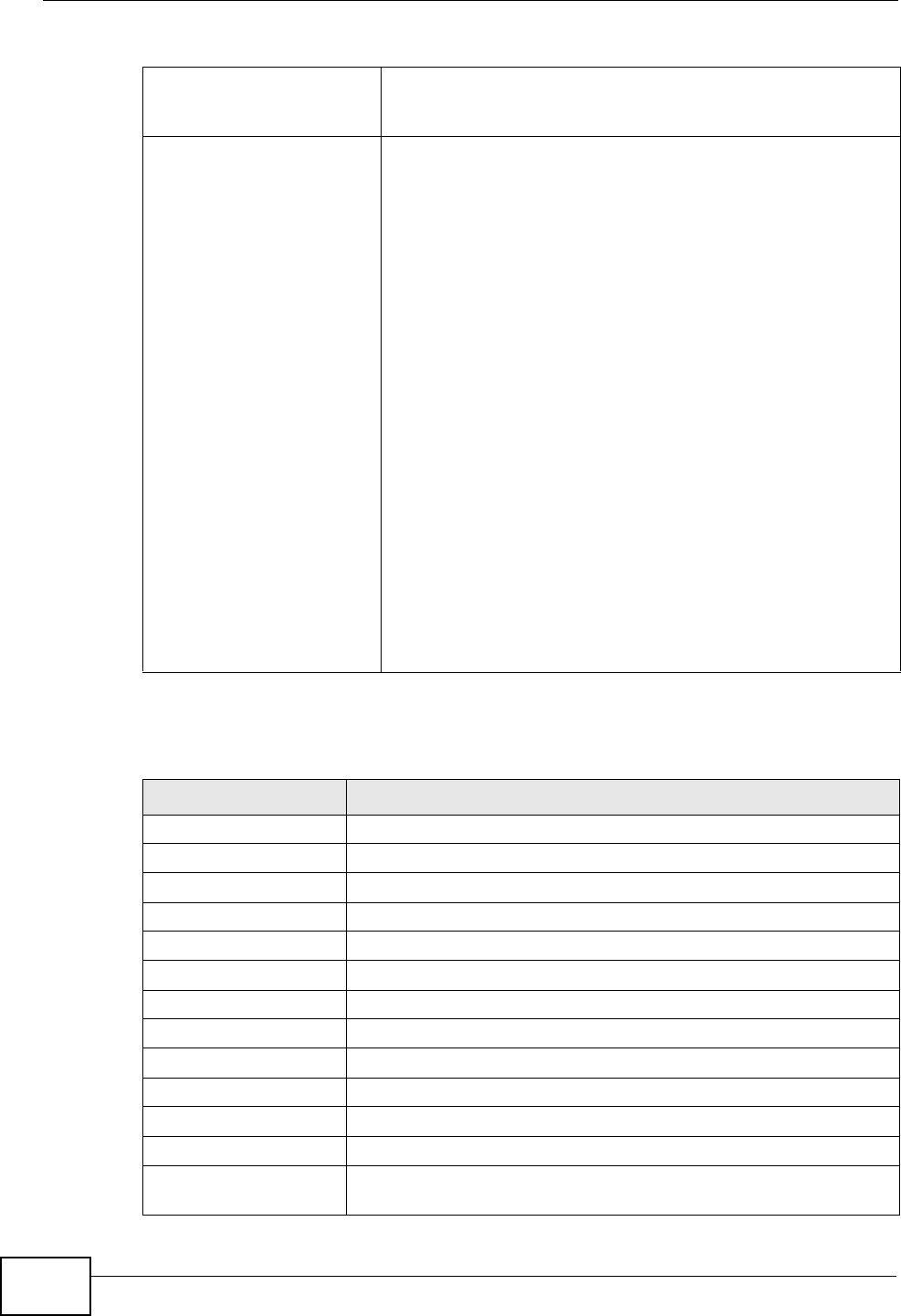
Chapter 24 Product Specifications
P-660HN-Tx User’s Guide
232
The following list, which is not exhaustive, illustrates the standards supported in
the ZyXEL Device.
WMM QoS WMM (Wi-Fi MultiMedia) QoS (Quality of Service) allows you
to prioritize wireless traffic according to the delivery
requirements of individual services.
Other Wireless Features WDS(wireless client: G-570S v2)
IEEE 802.11n Compliance
Frequency Range:2.4 GHz
Advanced Orthogonal Frequency Division Multiplexing
(OFDM)
2x2 Wireless Configuration
Data Rates:300Mbps and Auto Fallback
EIRP: 22dBm
Wired Equivalent Privacy (WEP) Data Encryption 64/128
WLAN bridge to LAN
16 MAC Address filter
WPA-PSK, WPA2-PSK
WPS
IEEE 802.1x (EAP-MD5, TLS and TTLS)
WMM
Multi BSSID (4 BSSIDs)
Table 79 Standards Supported
STANDARD DESCRIPTION
RFC 867 Daytime Protocol
RFC 868 Time Protocol
RFC 1058 RIP-1 (Routing Information Protocol)
RFC 1112 IGMP v1
RFC 1305 Network Time Protocol (NTP version 3)
RFC 1483 Multiprotocol Encapsulation over ATM Adaptation Layer 5
RFC 1631 IP Network Address Translator (NAT)
RFC 1661 The Point-to-Point Protocol (PPP)
RFC 1723 RIP-2 (Routing Information Protocol)
RFC 1981 Path MTU Discovery for IPv6
RFC 2236 IGMP v2
RFC 2364 PPP over AAL5 (PPP over ATM over ADSL)
RFC 2408 Internet Security Association and Key Management Protocol
(ISAKMP)
Table 78 Wireless Features

Chapter 24 Product Specifications
P-660HN-Tx User’s Guide 233
RFC 2460 IPv6 Specification
RFC 2516 A Method for Transmitting PPP Over Ethernet (PPPoE)
RFC 2684 Multiprotocol Encapsulation over ATM Adaptation Layer 5.
RFC 2766 Network Address Translation - Protocol
RFC 3484 Default Address Selection for IPv6
RFC 4291 IPv6 Addressing Architecture
RFC 4443 ICMPv6
RFC 4861 Neighbor Discovery for IPv6
RFC 4862 IPv6 Stateless Address Autoconfiguration
IEEE 802.11 Also known by the brand Wi-Fi, denotes a set of Wireless LAN/
WLAN standards developed by working group 11 of the IEEE
LAN/MAN Standards Committee (IEEE 802).
IEEE 802.11b Uses the 2.4 gigahertz (GHz) band
IEEE 802.11g Uses the 2.4 gigahertz (GHz) band
IEEE 802.11n Uses the 2.4 gigahertz (GHz) band
IEEE 802.11g+ Turbo and Super G modes
IEEE 802.11d Standard for Local and Metropolitan Area Networks: Media
Access Control (MAC) Bridges
IEEE 802.11x Port Based Network Access Control.
IEEE 802.11e QoS IEEE 802.11 e Wireless LAN for Quality of Service
ANSI T1.413, Issue 2 Asymmetric Digital Subscriber Line (ADSL) standard.
G dmt(G.992.1) G.992.1 Asymmetrical Digital Subscriber Line (ADSL)
Transceivers
ITU G.992.1 (G.DMT) ITU standard for ADSL using discrete multitone modulation.
ITU G.992.2 (G. Lite) ITU standard for ADSL using discrete multitone modulation.
ITU G.992.3
(G.dmt.bis)
ITU standard (also referred to as ADSL2) that extends the
capability of basic ADSL in data rates.
ITU G.992.4
(G.lite.bis)
ITU standard (also referred to as ADSL2) that extends the
capability of basic ADSL in data rates.
ITU G.992.5 (ADSL2+) ITU standard (also referred to as ADSL2+) that extends the
capability of basic ADSL by doubling the number of downstream
bits.
Microsoft PPTP MS PPTP (Microsoft's implementation of Point to Point Tunneling
Protocol)
MBM v2 Media Bandwidth Management v2
RFC 2383 ST2+ over ATM Protocol Specification - UNI 3.1 Version
TR-069 TR-069 DSL Forum Standard for CPE Wan Management.
1.363.5 Compliant AAL5 SAR (Segmentation And Re-assembly)
Table 79 Standards Supported (continued)
STANDARD DESCRIPTION

Chapter 24 Product Specifications
P-660HN-Tx User’s Guide
234
24.4 Power Adaptor Specifications
Table 80 ZyXEL Device Series Power Adaptor Specifications
AC POWER ADAPTER
MODEL 12V 0.5A SWITCHING PA
Input Power 100~240V-50/60HZ
Output Power DC 12Volts/0.5A
Power Consumption 7Watt max
Safety Standards EN 60950-1:2006/A11:2009
AC POWER ADAPTER
MODEL 12V 1A SWITCHING PA
Input Power 100~240V-50/60HZ
Output Power DC 12Volts/1A
Power Consumption 7Watt max
Safety Standards EN 60950-1:2006/A11:2009

P-660HN-Tx User’s Guide 235
APPENDIX A
Setting up Your Computer’s IP
Address
All computers must have a 10M or 100M Ethernet adapter card and TCP/IP
installed.
Windows 95/98/Me/NT/2000/XP/Vista, Macintosh OS 7 and later operating
systems and all versions of UNIX/LINUX include the software components you
need to install and use TCP/IP on your computer. Windows 3.1 requires the
purchase of a third-party TCP/IP application package.
TCP/IP should already be installed on computers using Windows NT/2000/XP,
Macintosh OS 7 and later operating systems.
After the appropriate TCP/IP components are installed, configure the TCP/IP
settings in order to "communicate" with your network.
If you manually assign IP information instead of using dynamic assignment, make
sure that your computers have IP addresses that place them in the same subnet
as the ZyXEL Device’s LAN port.
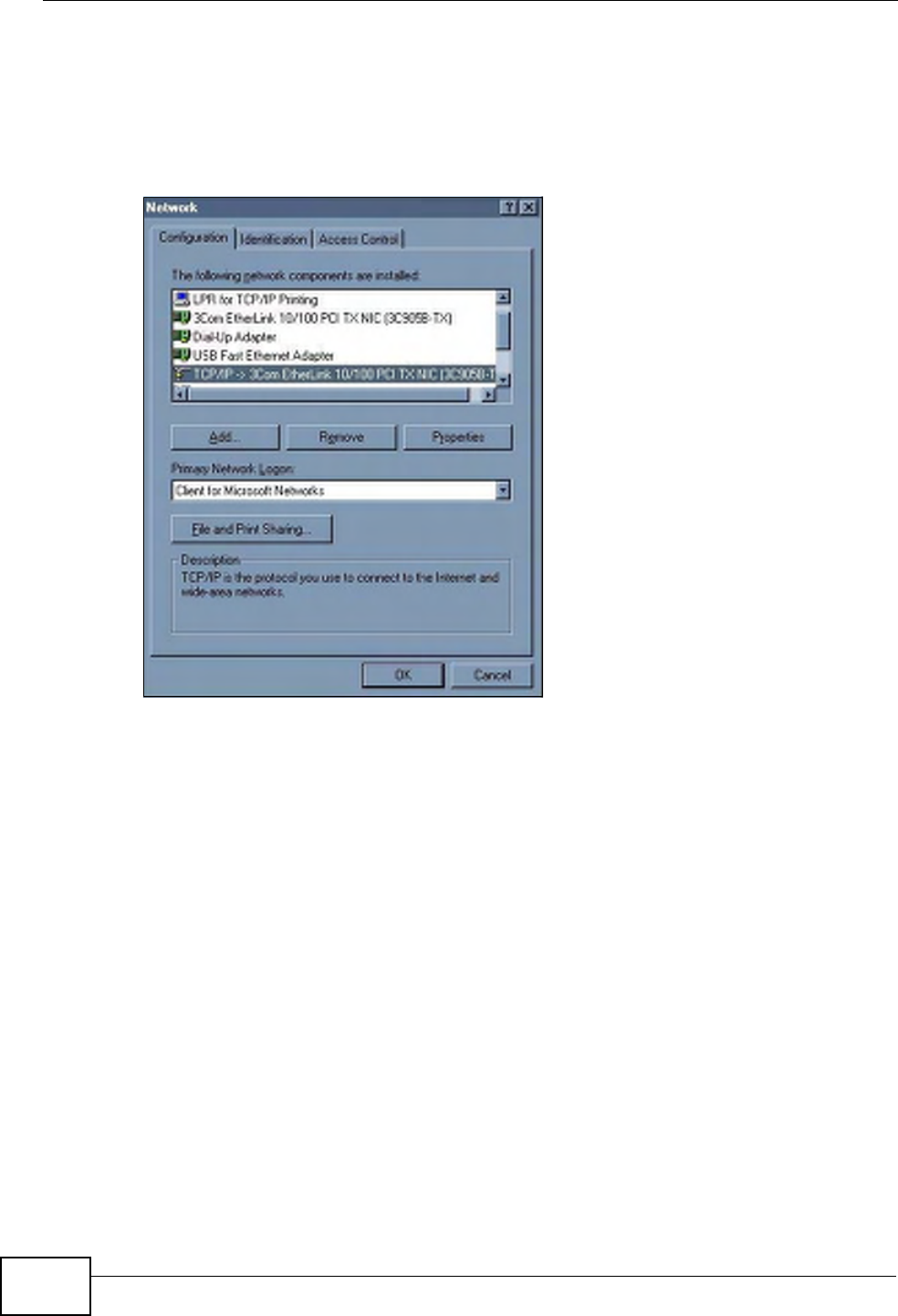
Appendix A Setting up Your Computer’s IP Address
P-660HN-Tx User’s Guide
236
Windows 95/98/Me
Click Start, Settings, Control Panel and double-click the Network icon to open
the Network window.
Figure 111 WIndows 95/98/Me: Network: Configuration
Installing Components
The Network window Configuration tab displays a list of installed components.
You need a network adapter, the TCP/IP protocol and Client for Microsoft
Networks.
If you need the adapter:
1In the Network window, click Add.
2Select Adapter and then click Add.
3Select the manufacturer and model of your network adapter and then click OK.
If you need TCP/IP:
1In the Network window, click Add.
2Select Protocol and then click Add.
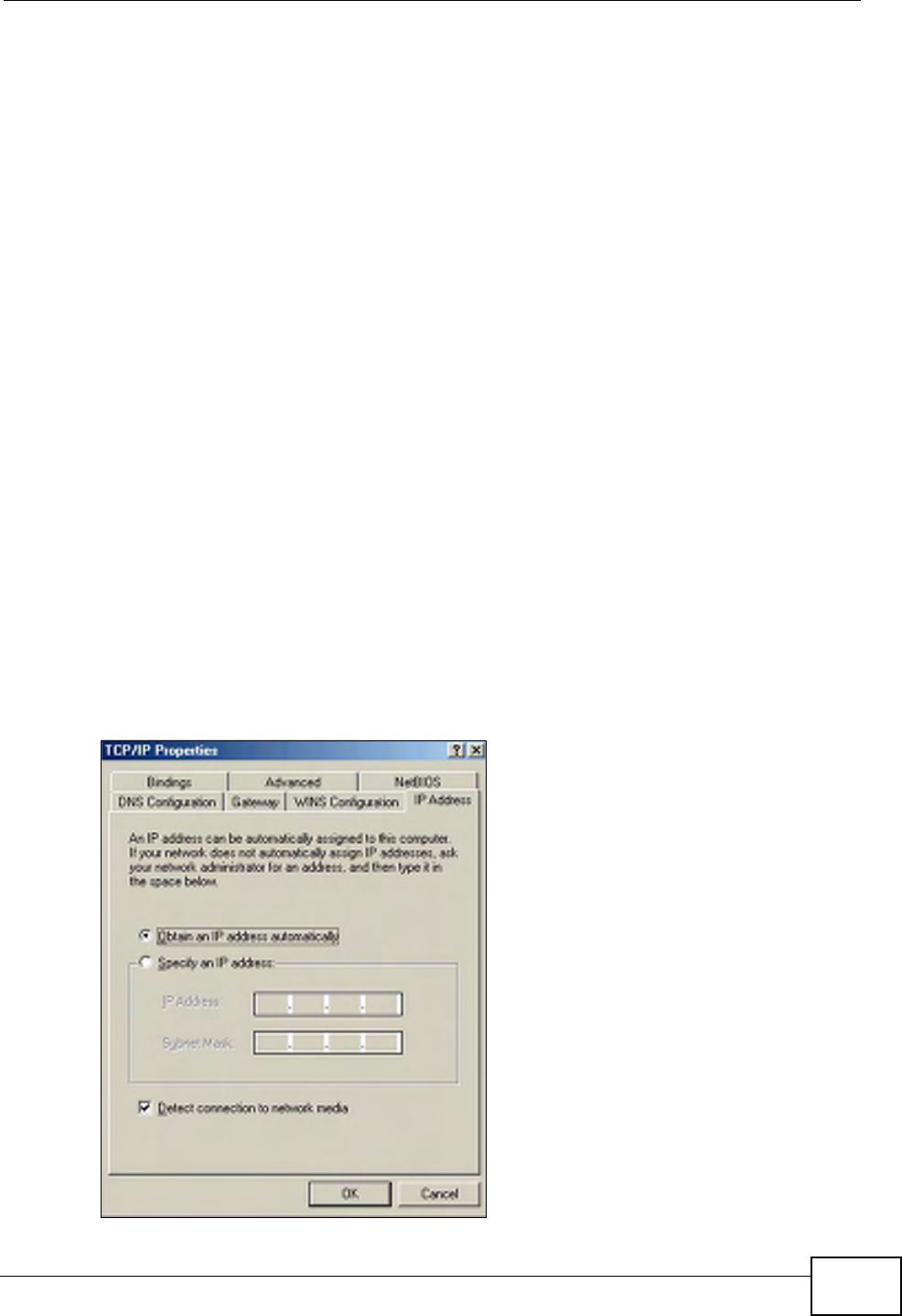
Appendix A Setting up Your Computer’s IP Address
P-660HN-Tx User’s Guide 237
3Select Microsoft from the list of manufacturers.
4Select TCP/IP from the list of network protocols and then click OK.
If you need Client for Microsoft Networks:
1Click Add.
2Select Client and then click Add.
3Select Microsoft from the list of manufacturers.
4Select Client for Microsoft Networks from the list of network clients and then
click OK.
5Restart your computer so the changes you made take effect.
Configuring
1In the Network window Configuration tab, select your network adapter's TCP/IP
entry and click Properties
2Click the IP Address tab.
• If your IP address is dynamic, select Obtain an IP address automatically.
• If you have a static IP address, select Specify an IP address and type your
information into the IP Address and Subnet Mask fields.
Figure 112 Windows 95/98/Me: TCP/IP Properties: IP Address
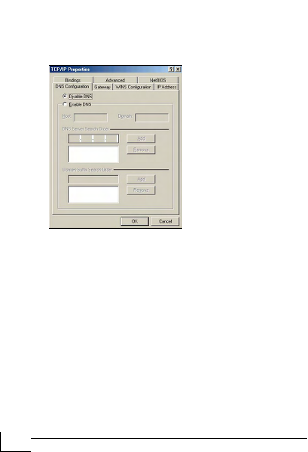
Appendix A Setting up Your Computer’s IP Address
P-660HN-Tx User’s Guide
238
3Click the DNS Configuration tab.
• If you do not know your DNS information, select Disable DNS.
• If you know your DNS information, select Enable DNS and type the
information in the fields below (you may not need to fill them all in).
Figure 113 Windows 95/98/Me: TCP/IP Properties: DNS Configuration
4Click the Gateway tab.
• If you do not know your gateway’s IP address, remove previously installed
gateways.
• If you have a gateway IP address, type it in the New gateway field and click
Add.
5Click OK to save and close the TCP/IP Properties window.
6Click OK to close the Network window. Insert the Windows CD if prompted.
7Turn on your ZyXEL Device and restart your computer when prompted.
Verifying Settings
1Click Start and then Run.
2In the Run window, type "winipcfg" and then click OK to open the IP
Configuration window.
3Select your network adapter. You should see your computer's IP address, subnet
mask and default gateway.
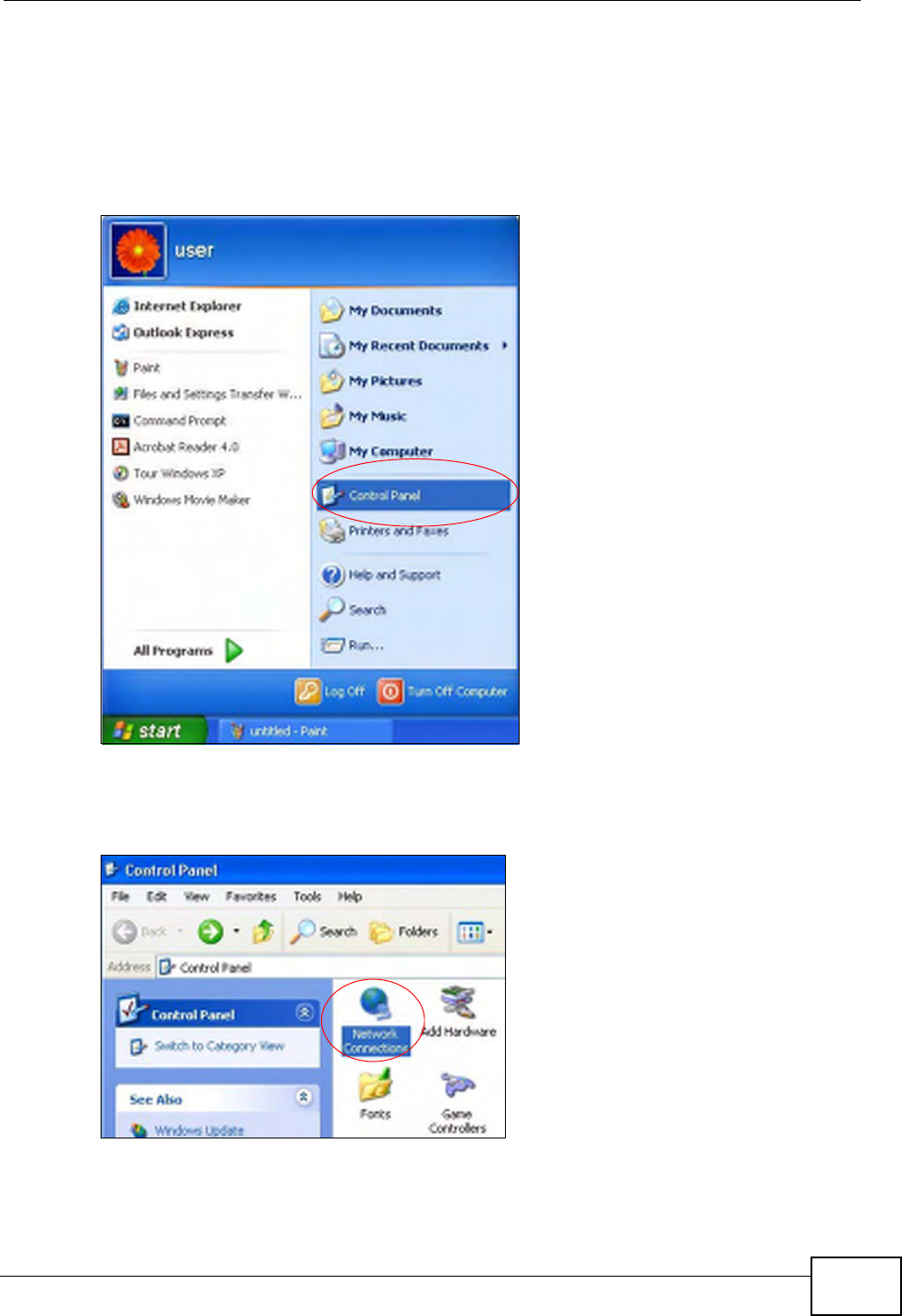
Appendix A Setting up Your Computer’s IP Address
P-660HN-Tx User’s Guide 239
Windows 2000/NT/XP
The following example figures use the default Windows XP GUI theme.
1Click start (Start in Windows 2000/NT), Settings, Control Panel.
Figure 114 Windows XP: Start Menu
2In the Control Panel, double-click Network Connections (Network and Dial-
up Connections in Windows 2000/NT).
Figure 115 Windows XP: Control Panel
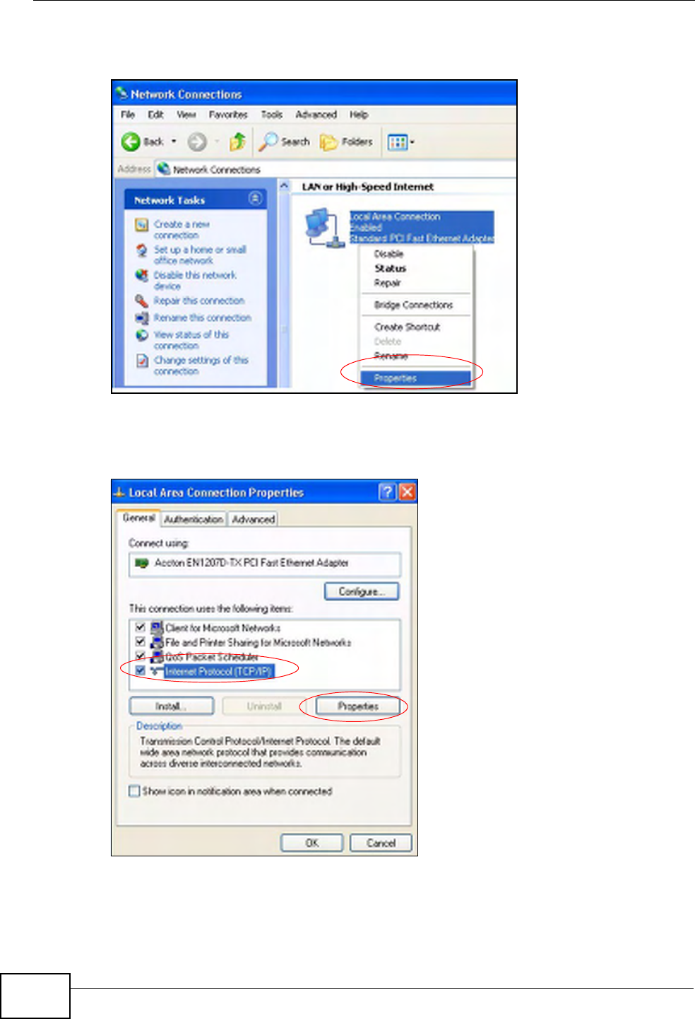
Appendix A Setting up Your Computer’s IP Address
P-660HN-Tx User’s Guide
240
3Right-click Local Area Connection and then click Properties.
Figure 116 Windows XP: Control Panel: Network Connections: Properties
4Select Internet Protocol (TCP/IP) (under the General tab in Win XP) and then
click Properties.
Figure 117 Windows XP: Local Area Connection Properties
5The Internet Protocol TCP/IP Properties window opens (the General tab in
Windows XP).
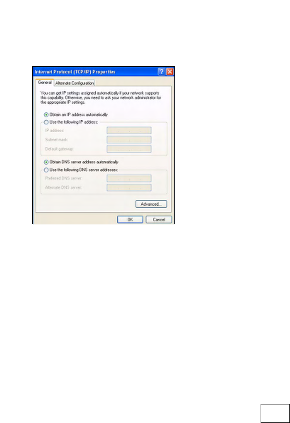
Appendix A Setting up Your Computer’s IP Address
P-660HN-Tx User’s Guide 241
•If you have a dynamic IP address click Obtain an IP address
automatically.
• If you have a static IP address click Use the following IP Address and fill in
the IP address, Subnet mask, and Default gateway fields.
•Click Advanced.
Figure 118 Windows XP: Internet Protocol (TCP/IP) Properties
6 If you do not know your gateway's IP address, remove any previously installed
gateways in the IP Settings tab and click OK.
Do one or more of the following if you want to configure additional IP addresses:
•In the IP Settings tab, in IP addresses, click Add.
•In TCP/IP Address, type an IP address in IP address and a subnet mask in
Subnet mask, and then click Add.
• Repeat the above two steps for each IP address you want to add.
• Configure additional default gateways in the IP Settings tab by clicking Add
in Default gateways.
•In TCP/IP Gateway Address, type the IP address of the default gateway in
Gateway. To manually configure a default metric (the number of transmission
hops), clear the Automatic metric check box and type a metric in Metric.
•Click Add.
• Repeat the previous three steps for each default gateway you want to add.
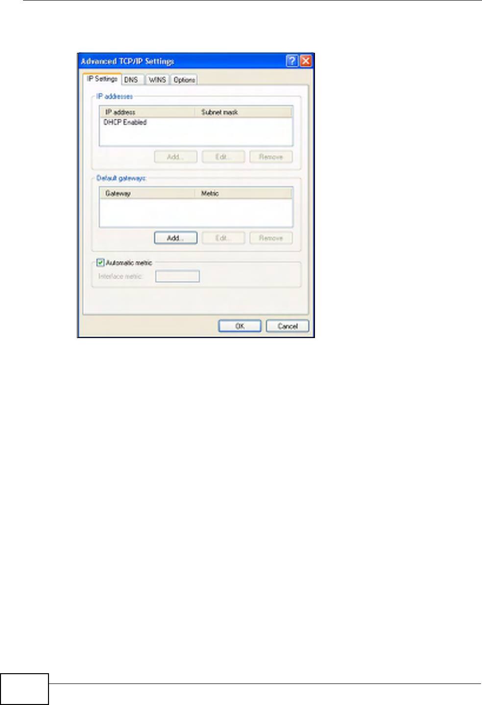
Appendix A Setting up Your Computer’s IP Address
P-660HN-Tx User’s Guide
242
•Click OK when finished.
Figure 119 Windows XP: Advanced TCP/IP Properties
7In the Internet Protocol TCP/IP Properties window (the General tab in
Windows XP):
•Click Obtain DNS server address automatically if you do not know your
DNS server IP address(es).
• If you know your DNS server IP address(es), click Use the following DNS
server addresses, and type them in the Preferred DNS server and
Alternate DNS server fields.
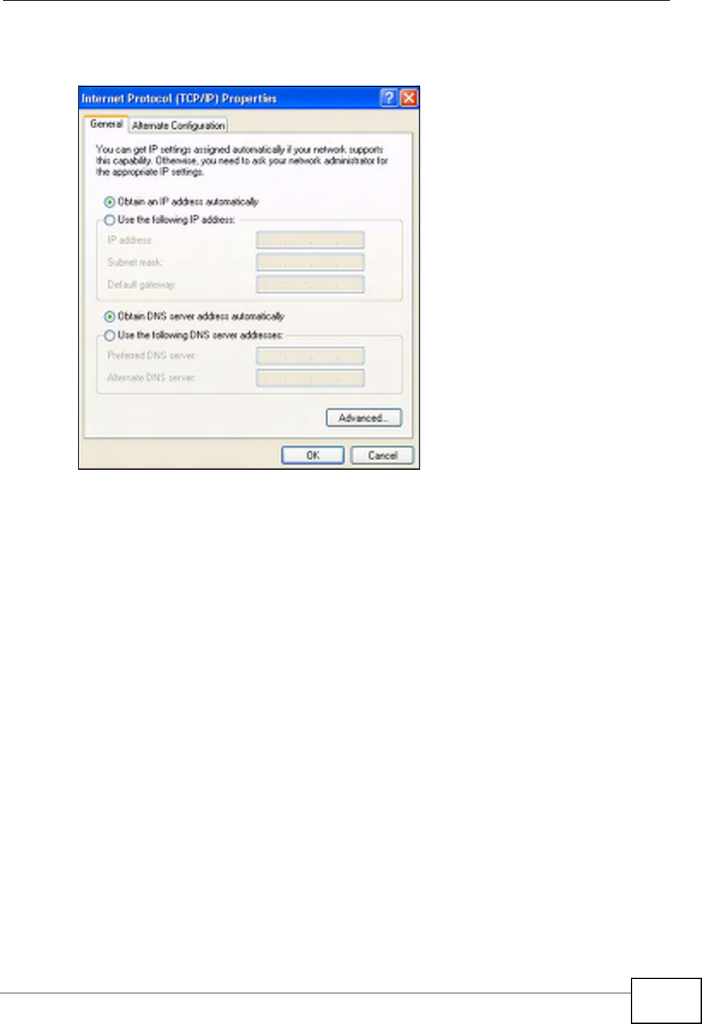
Appendix A Setting up Your Computer’s IP Address
P-660HN-Tx User’s Guide 243
If you have previously configured DNS servers, click Advanced and then the
DNS tab to order them.
Figure 120 Windows XP: Internet Protocol (TCP/IP) Properties
8Click OK to close the Internet Protocol (TCP/IP) Properties window.
9Click Close (OK in Windows 2000/NT) to close the Local Area Connection
Properties window.
10 Close the Network Connections window (Network and Dial-up Connections
in Windows 2000/NT).
11 Turn on your ZyXEL Device and restart your computer (if prompted).
Verifying Settings
1Click Start, All Programs, Accessories and then Command Prompt.
2In the Command Prompt window, type "ipconfig" and then press [ENTER]. You
can also open Network Connections, right-click a network connection, click
Status and then click the Support tab.
Windows Vista
This section shows screens from Windows Vista Enterprise Version 6.0.
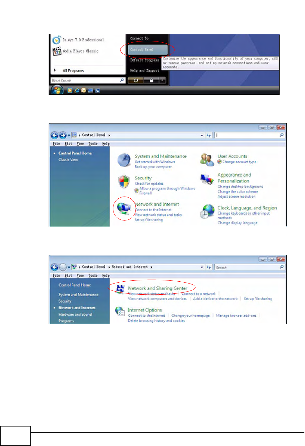
Appendix A Setting up Your Computer’s IP Address
P-660HN-Tx User’s Guide
244
1Click the Start icon, Control Panel.
Figure 121 Windows Vista: Start Menu
2In the Control Panel, double-click Network and Internet.
Figure 122 Windows Vista: Control Panel
3Click Network and Sharing Center.
Figure 123 Windows Vista: Network And Internet
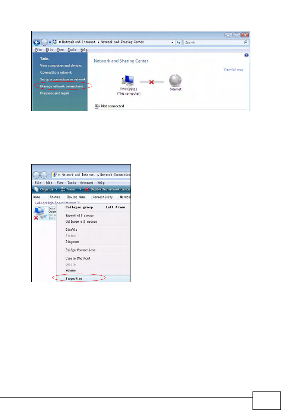
Appendix A Setting up Your Computer’s IP Address
P-660HN-Tx User’s Guide 245
4Click Manage network connections.
Figure 124 Windows Vista: Network and Sharing Center
5Right-click Local Area Connection and then click Properties.
Note: During this procedure, click Continue whenever Windows displays a screen
saying that it needs your permission to continue.
Figure 125 Windows Vista: Network and Sharing Center
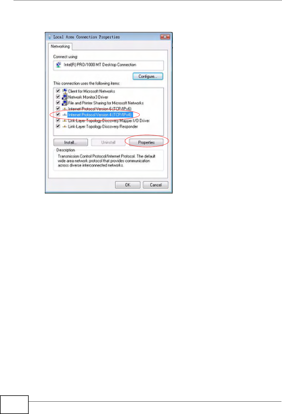
Appendix A Setting up Your Computer’s IP Address
P-660HN-Tx User’s Guide
246
6Select Internet Protocol Version 4 (TCP/IPv4) and click Properties.
Figure 126 Windows Vista: Local Area Connection Properties
7The Internet Protocol Version 4 (TCP/IPv4) Properties window opens (the
General tab).
• If you have a dynamic IP address click Obtain an IP address
automatically.
• If you have a static IP address click Use the following IP address and fill in
the IP address, Subnet mask, and Default gateway fields.
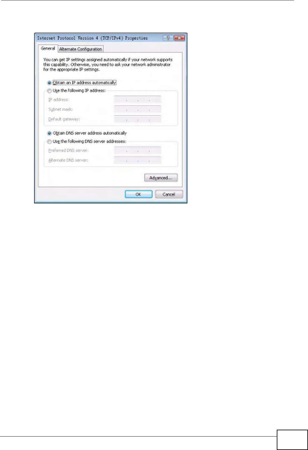
Appendix A Setting up Your Computer’s IP Address
P-660HN-Tx User’s Guide 247
•Click Advanced.
Figure 127 Windows Vista: Internet Protocol Version 4 (TCP/IPv4) Properties
8 If you do not know your gateway's IP address, remove any previously installed
gateways in the IP Settings tab and click OK.
Do one or more of the following if you want to configure additional IP addresses:
•In the IP Settings tab, in IP addresses, click Add.
•In TCP/IP Address, type an IP address in IP address and a subnet mask in
Subnet mask, and then click Add.
• Repeat the above two steps for each IP address you want to add.
• Configure additional default gateways in the IP Settings tab by clicking Add
in Default gateways.
•In TCP/IP Gateway Address, type the IP address of the default gateway in
Gateway. To manually configure a default metric (the number of transmission
hops), clear the Automatic metric check box and type a metric in Metric.
•Click Add.
• Repeat the previous three steps for each default gateway you want to add.
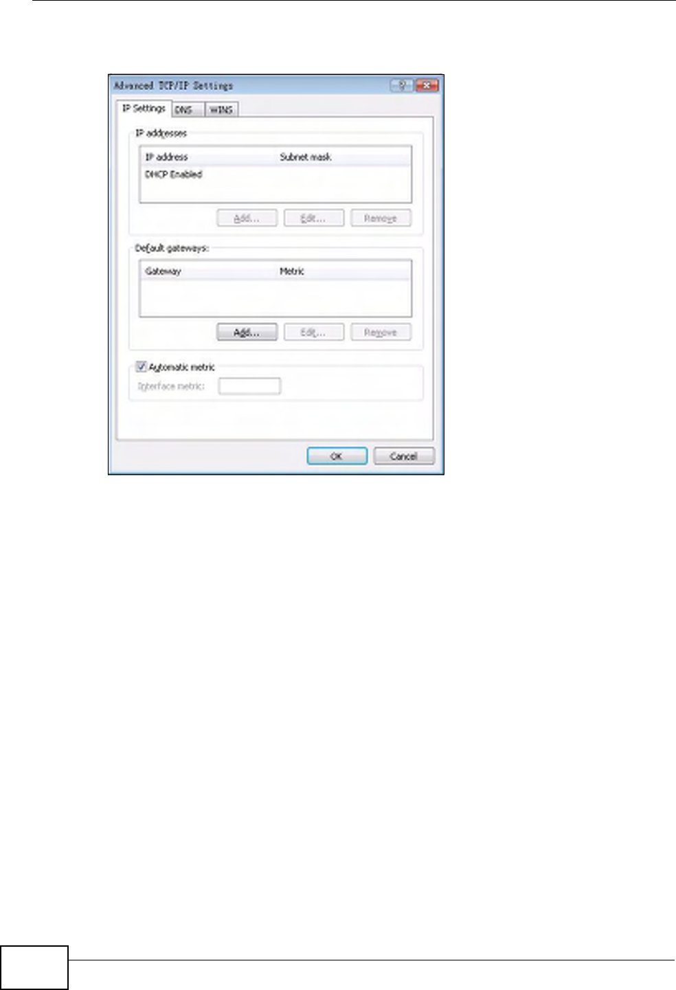
Appendix A Setting up Your Computer’s IP Address
P-660HN-Tx User’s Guide
248
•Click OK when finished.
Figure 128 Windows Vista: Advanced TCP/IP Properties
9In the Internet Protocol Version 4 (TCP/IPv4) Properties window, (the
General tab):
•Click Obtain DNS server address automatically if you do not know your
DNS server IP address(es).
• If you know your DNS server IP address(es), click Use the following DNS
server addresses, and type them in the Preferred DNS server and
Alternate DNS server fields.
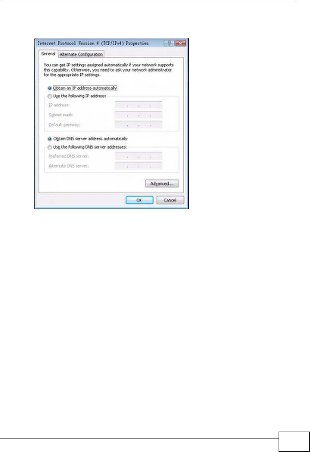
Appendix A Setting up Your Computer’s IP Address
P-660HN-Tx User’s Guide 249
If you have previously configured DNS servers, click Advanced and then the
DNS tab to order them.
Figure 129 Windows Vista: Internet Protocol Version 4 (TCP/IPv4) Properties
10 Click OK to close the Internet Protocol Version 4 (TCP/IPv4) Properties
window.
11 Click Close to close the Local Area Connection Properties window.
12 Close the Network Connections window.
13 Turn on your ZyXEL Device and restart your computer (if prompted).
Verifying Settings
1Click Start, All Programs, Accessories and then Command Prompt.
2In the Command Prompt window, type "ipconfig" and then press [ENTER]. You
can also open Network Connections, right-click a network connection, click
Status and then click the Support tab.
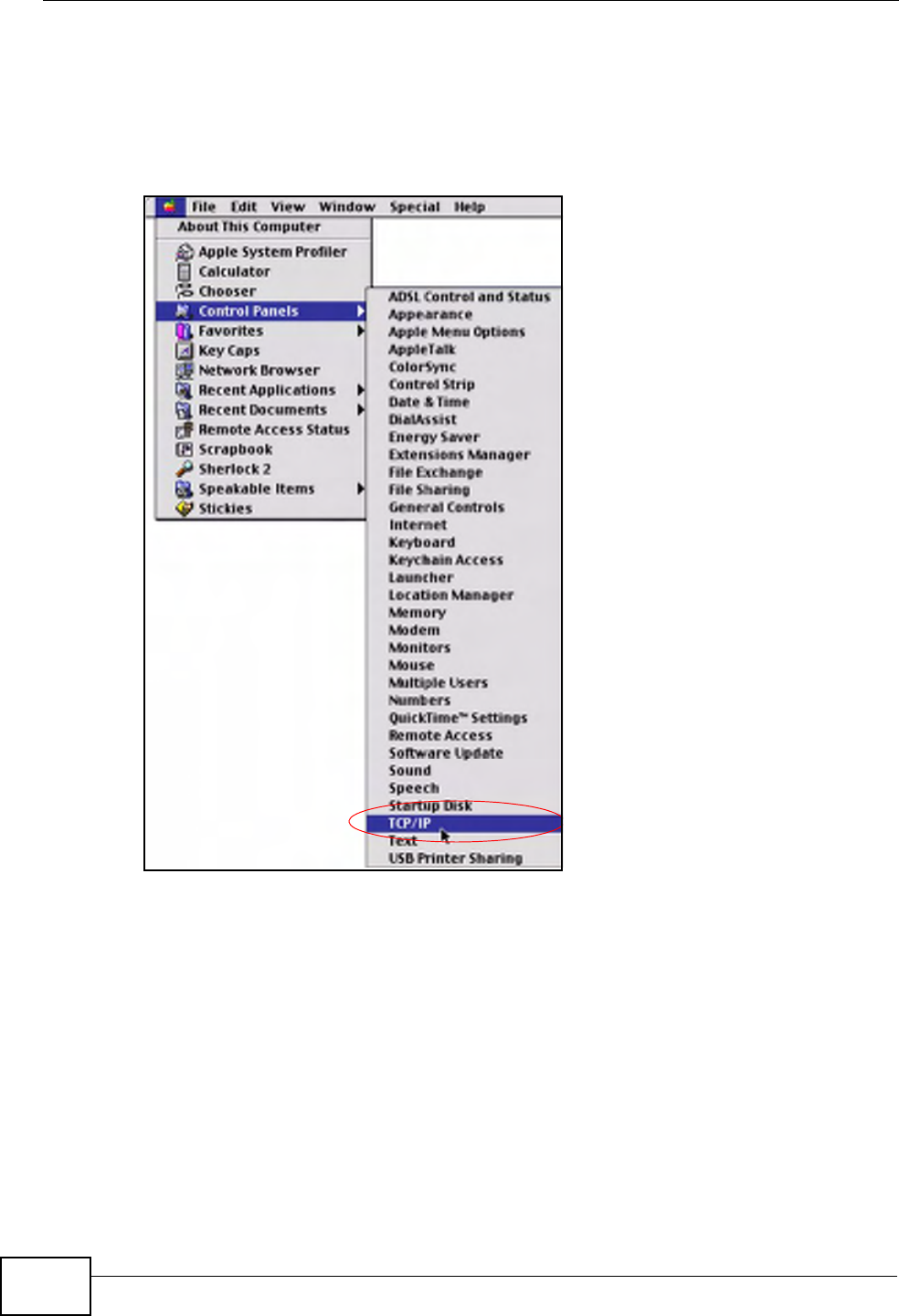
Appendix A Setting up Your Computer’s IP Address
P-660HN-Tx User’s Guide
250
Macintosh OS 8/9
1Click the Apple menu, Control Panel and double-click TCP/IP to open the TCP/
IP Control Panel.
Figure 130 Macintosh OS 8/9: Apple Menu
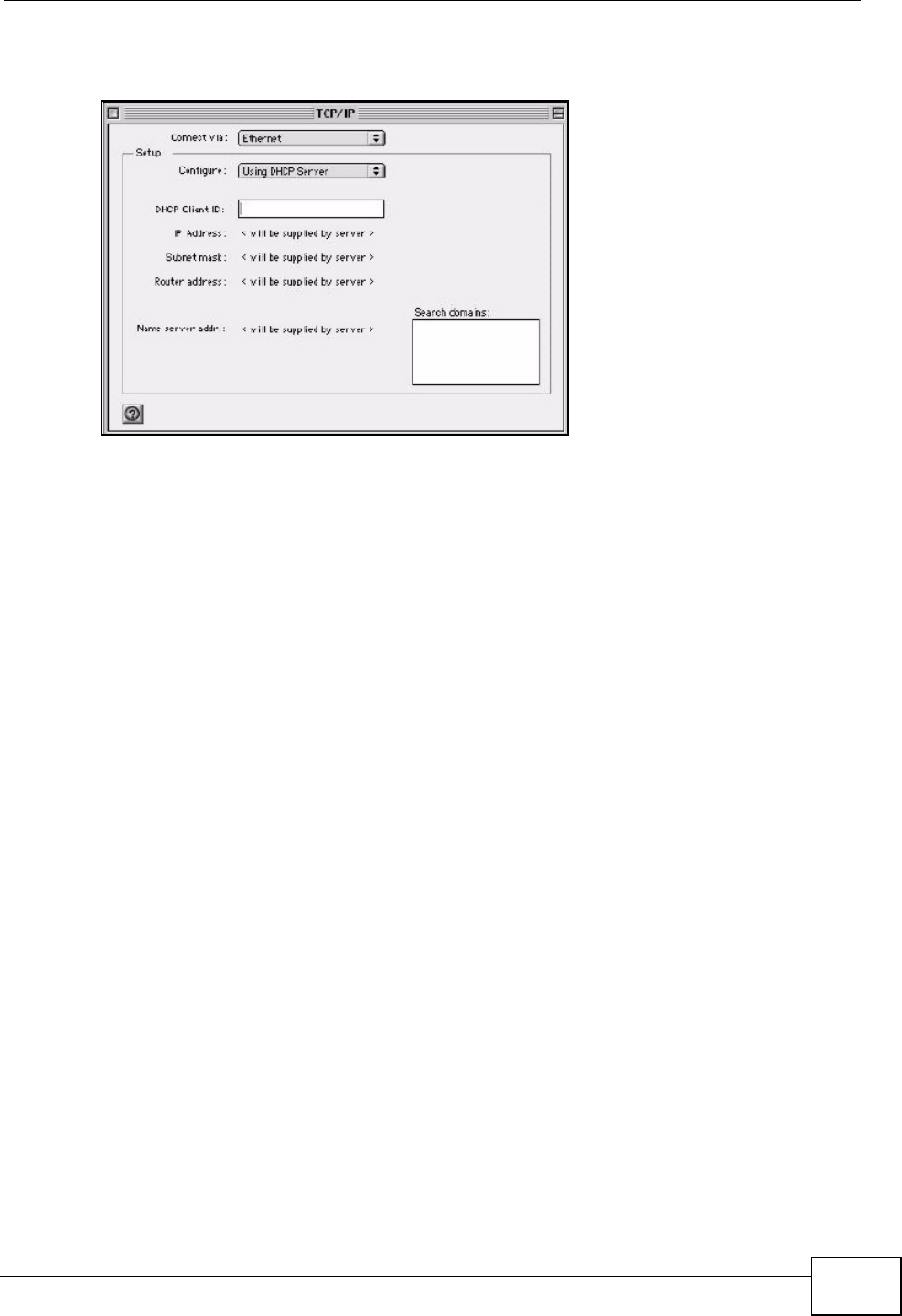
Appendix A Setting up Your Computer’s IP Address
P-660HN-Tx User’s Guide 251
2Select Ethernet built-in from the Connect via list.
Figure 131 Macintosh OS 8/9: TCP/IP
3For dynamically assigned settings, select Using DHCP Server from the
Configure: list.
4For statically assigned settings, do the following:
•From the Configure box, select Manually.
• Type your IP address in the IP Address box.
• Type your subnet mask in the Subnet mask box.
• Type the IP address of your ZyXEL Device in the Router address box.
5Close the TCP/IP Control Panel.
6Click Save if prompted, to save changes to your configuration.
7Turn on your ZyXEL Device and restart your computer (if prompted).
Verifying Settings
Check your TCP/IP properties in the TCP/IP Control Panel window.
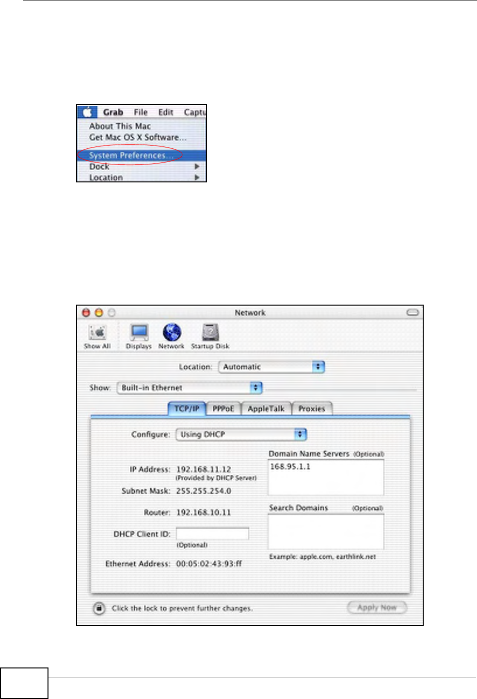
Appendix A Setting up Your Computer’s IP Address
P-660HN-Tx User’s Guide
252
Macintosh OS X
1Click the Apple menu, and click System Preferences to open the System
Preferences window.
Figure 132 Macintosh OS X: Apple Menu
2Click Network in the icon bar.
• Select Automatic from the Location list.
• Select Built-in Ethernet from the Show list.
•Click the TCP/IP tab.
3For dynamically assigned settings, select Using DHCP from the Configure list.
Figure 133 Macintosh OS X: Network
4For statically assigned settings, do the following:
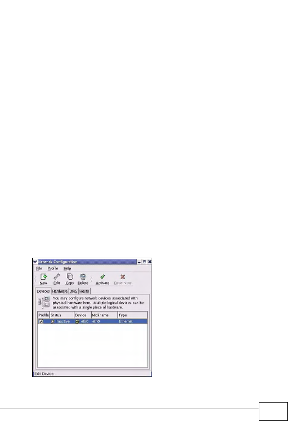
Appendix A Setting up Your Computer’s IP Address
P-660HN-Tx User’s Guide 253
•From the Configure box, select Manually.
• Type your IP address in the IP Address box.
• Type your subnet mask in the Subnet mask box.
• Type the IP address of your ZyXEL Device in the Router address box.
5Click Apply Now and close the window.
6Turn on your ZyXEL Device and restart your computer (if prompted).
Verifying Settings
Check your TCP/IP properties in the Network window.
Linux
This section shows you how to configure your computer’s TCP/IP settings in Red
Hat Linux 9.0. Procedure, screens and file location may vary depending on your
Linux distribution and release version.
Note: Make sure you are logged in as the root administrator.
Using the K Desktop Environment (KDE)
Follow the steps below to configure your computer IP address using the KDE.
1Click the Red Hat button (located on the bottom left corner), select System
Setting and click Network.
Figure 134 Red Hat 9.0: KDE: Network Configuration: Devices
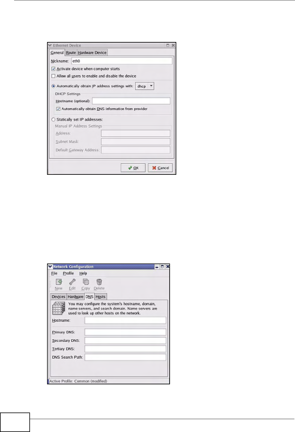
Appendix A Setting up Your Computer’s IP Address
P-660HN-Tx User’s Guide
254
2Double-click on the profile of the network card you wish to configure. The
Ethernet Device General screen displays as shown.
Figure 135 Red Hat 9.0: KDE: Ethernet Device: General
• If you have a dynamic IP address, click Automatically obtain IP address
settings with and select dhcp from the drop down list.
• If you have a static IP address, click Statically set IP Addresses and fill in
the Address, Subnet mask, and Default Gateway Address fields.
3Click OK to save the changes and close the Ethernet Device General screen.
4If you know your DNS server IP address(es), click the DNS tab in the Network
Configuration screen. Enter the DNS server information in the fields provided.
Figure 136 Red Hat 9.0: KDE: Network Configuration: DNS
5Click the Devices tab.
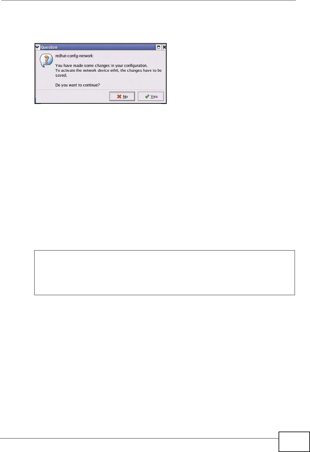
Appendix A Setting up Your Computer’s IP Address
P-660HN-Tx User’s Guide 255
6Click the Activate button to apply the changes. The following screen displays.
Click Yes to save the changes in all screens.
Figure 137 Red Hat 9.0: KDE: Network Configuration: Activate
7After the network card restart process is complete, make sure the Status is
Active in the Network Configuration screen.
Using Configuration Files
Follow the steps below to edit the network configuration files and set your
computer IP address.
1Assuming that you have only one network card on the computer, locate the
ifconfig-eth0 configuration file (where eth0 is the name of the Ethernet card).
Open the configuration file with any plain text editor.
• If you have a dynamic IP address, enter dhcp in the BOOTPROTO= field. The
following figure shows an example.
Figure 138 Red Hat 9.0: Dynamic IP Address Setting in ifconfig-eth0
DEVICE=eth0
ONBOOT=yes
BOOTPROTO=dhcp
USERCTL=no
PEERDNS=yes
TYPE=Ethernet
Appendix A Setting up Your Computer’s IP Address
P-660HN-Tx User’s Guide
256
•If you have a static IP address, enter static in the BOOTPROTO= field. Type
IPADDR= followed by the IP address (in dotted decimal notation) and type
NETMASK= followed by the subnet mask. The following example shows an
example where the static IP address is 192.168.1.10 and the subnet mask is
255.255.255.0.
Figure 139 Red Hat 9.0: Static IP Address Setting in ifconfig-eth0
2If you know your DNS server IP address(es), enter the DNS server information in
the resolv.conf file in the /etc directory. The following figure shows an example
where two DNS server IP addresses are specified.
Figure 140 Red Hat 9.0: DNS Settings in resolv.conf
3After you edit and save the configuration files, you must restart the network card.
Enter ./network restart in the /etc/rc.d/init.d directory. The following
figure shows an example.
Figure 141 Red Hat 9.0: Restart Ethernet Card
DEVICE=eth0
ONBOOT=yes
BOOTPROTO=static
IPADDR=192.168.1.10
NETMASK=255.255.255.0
USERCTL=no
PEERDNS=yes
TYPE=Ethernet
nameserver 172.23.5.1
nameserver 172.23.5.2
[root@localhost init.d]# network restart
Shutting down interface eth0: [OK]
Shutting down loopback interface: [OK]
Setting network parameters: [OK]
Bringing up loopback interface: [OK]
Bringing up interface eth0: [OK]

Appendix A Setting up Your Computer’s IP Address
P-660HN-Tx User’s Guide 257
Verifying Settings
Enter ifconfig in a terminal screen to check your TCP/IP properties.
Figure 142 Red Hat 9.0: Checking TCP/IP Properties
[root@localhost]# ifconfig
eth0 Link encap:Ethernet HWaddr 00:50:BA:72:5B:44
inet addr:172.23.19.129 Bcast:172.23.19.255 Mask:255.255.255.0
UP BROADCAST RUNNING MULTICAST MTU:1500 Metric:1
RX packets:717 errors:0 dropped:0 overruns:0 frame:0
TX packets:13 errors:0 dropped:0 overruns:0 carrier:0
collisions:0 txqueuelen:100
RX bytes:730412 (713.2 Kb) TX bytes:1570 (1.5 Kb)
Interrupt:10 Base address:0x1000
[root@localhost]#

Appendix A Setting up Your Computer’s IP Address
P-660HN-Tx User’s Guide
258

P-660HN-Tx User’s Guide 259
APPENDIX B
IP Addresses and Subnetting
This appendix introduces IP addresses and subnet masks.
IP addresses identify individual devices on a network. Every networking device
(including computers, servers, routers, printers, etc.) needs an IP address to
communicate across the network. These networking devices are also known as
hosts.
Subnet masks determine the maximum number of possible hosts on a network.
You can also use subnet masks to divide one network into multiple sub-networks.
Introduction to IP Addresses
One part of the IP address is the network number, and the other part is the host
ID. In the same way that houses on a street share a common street name, the
hosts on a network share a common network number. Similarly, as each house
has its own house number, each host on the network has its own unique
identifying number - the host ID. Routers use the network number to send packets
to the correct network, while the host ID determines to which host on the network
the packets are delivered.
Structure
An IP address is made up of four parts, written in dotted decimal notation (for
example, 192.168.1.1). Each of these four parts is known as an octet. An octet is
an eight-digit binary number (for example 11000000, which is 192 in decimal
notation).
Therefore, each octet has a possible range of 00000000 to 11111111 in binary, or
0 to 255 in decimal.
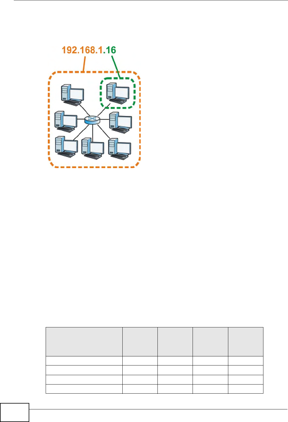
Appendix B IP Addresses and Subnetting
P-660HN-Tx User’s Guide
260
The following figure shows an example IP address in which the first three octets
(192.168.1) are the network number, and the fourth octet (16) is the host ID.
Figure 143 Network Number and Host ID
How much of the IP address is the network number and how much is the host ID
varies according to the subnet mask.
Subnet Masks
A subnet mask is used to determine which bits are part of the network number,
and which bits are part of the host ID (using a logical AND operation). The term
“subnet” is short for “sub-network”.
A subnet mask has 32 bits. If a bit in the subnet mask is a “1” then the
corresponding bit in the IP address is part of the network number. If a bit in the
subnet mask is “0” then the corresponding bit in the IP address is part of the host
ID.
The following example shows a subnet mask identifying the network number (in
bold text) and host ID of an IP address (192.168.1.2 in decimal).
Table 81 Subnet Masks
1ST
OCTET:
(192)
2ND
OCTET:
(168)
3RD
OCTET:
(1)
4TH
OCTET
(2)
IP Address (Binary) 11000000 10101000 00000001 00000010
Subnet Mask (Binary) 11111111 11111111 11111111 00000000
Network Number 11000000 10101000 00000001
Host ID 00000010

Appendix B IP Addresses and Subnetting
P-660HN-Tx User’s Guide 261
By convention, subnet masks always consist of a continuous sequence of ones
beginning from the leftmost bit of the mask, followed by a continuous sequence of
zeros, for a total number of 32 bits.
Subnet masks can be referred to by the size of the network number part (the bits
with a “1” value). For example, an “8-bit mask” means that the first 8 bits of the
mask are ones and the remaining 24 bits are zeroes.
Subnet masks are expressed in dotted decimal notation just like IP addresses. The
following examples show the binary and decimal notation for 8-bit, 16-bit, 24-bit
and 29-bit subnet masks.
Network Size
The size of the network number determines the maximum number of possible
hosts you can have on your network. The larger the number of network number
bits, the smaller the number of remaining host ID bits.
An IP address with host IDs of all zeros is the IP address of the network
(192.168.1.0 with a 24-bit subnet mask, for example). An IP address with host
IDs of all ones is the broadcast address for that network (192.168.1.255 with a
24-bit subnet mask, for example).
As these two IP addresses cannot be used for individual hosts, calculate the
maximum number of possible hosts in a network as follows:
Table 82 Subnet Masks
BINARY
DECIMAL
1ST
OCTET
2ND
OCTET
3RD
OCTET
4TH
OCTET
8-bit mask 11111111 00000000 00000000 00000000 255.0.0.0
16-bit
mask
11111111 11111111 00000000 00000000 255.255.0.0
24-bit
mask
11111111 11111111 11111111 00000000 255.255.255.0
29-bit
mask
11111111 11111111 11111111 11111000 255.255.255.24
8
Table 83 Maximum Host Numbers
SUBNET MASK HOST ID SIZE MAXIMUM NUMBER OF
HOSTS
8 bits 255.0.0.0 24 bits 224 – 2 16777214
16 bits 255.255.0.0 16 bits 216 – 2 65534
24 bits 255.255.255.0 8 bits 28 – 2 254
29 bits 255.255.255.2
48
3 bits 23 – 2 6
Appendix B IP Addresses and Subnetting
P-660HN-Tx User’s Guide
262
Notation
Since the mask is always a continuous number of ones beginning from the left,
followed by a continuous number of zeros for the remainder of the 32 bit mask,
you can simply specify the number of ones instead of writing the value of each
octet. This is usually specified by writing a “/” followed by the number of bits in
the mask after the address.
For example, 192.1.1.0 /25 is equivalent to saying 192.1.1.0 with subnet mask
255.255.255.128.
The following table shows some possible subnet masks using both notations.
Subnetting
You can use subnetting to divide one network into multiple sub-networks. In the
following example a network administrator creates two sub-networks to isolate a
group of servers from the rest of the company network for security reasons.
In this example, the company network address is 192.168.1.0. The first three
octets of the address (192.168.1) are the network number, and the remaining
octet is the host ID, allowing a maximum of 28 – 2 or 254 possible hosts.
Table 84 Alternative Subnet Mask Notation
SUBNET MASK ALTERNATIVE
NOTATION
LAST OCTET
(BINARY)
LAST OCTET
(DECIMAL)
255.255.255.0 /24 0000 0000 0
255.255.255.128 /25 1000 0000 128
255.255.255.192 /26 1100 0000 192
255.255.255.224 /27 1110 0000 224
255.255.255.240 /28 1111 0000 240
255.255.255.248 /29 1111 1000 248
255.255.255.252 /30 1111 1100 252
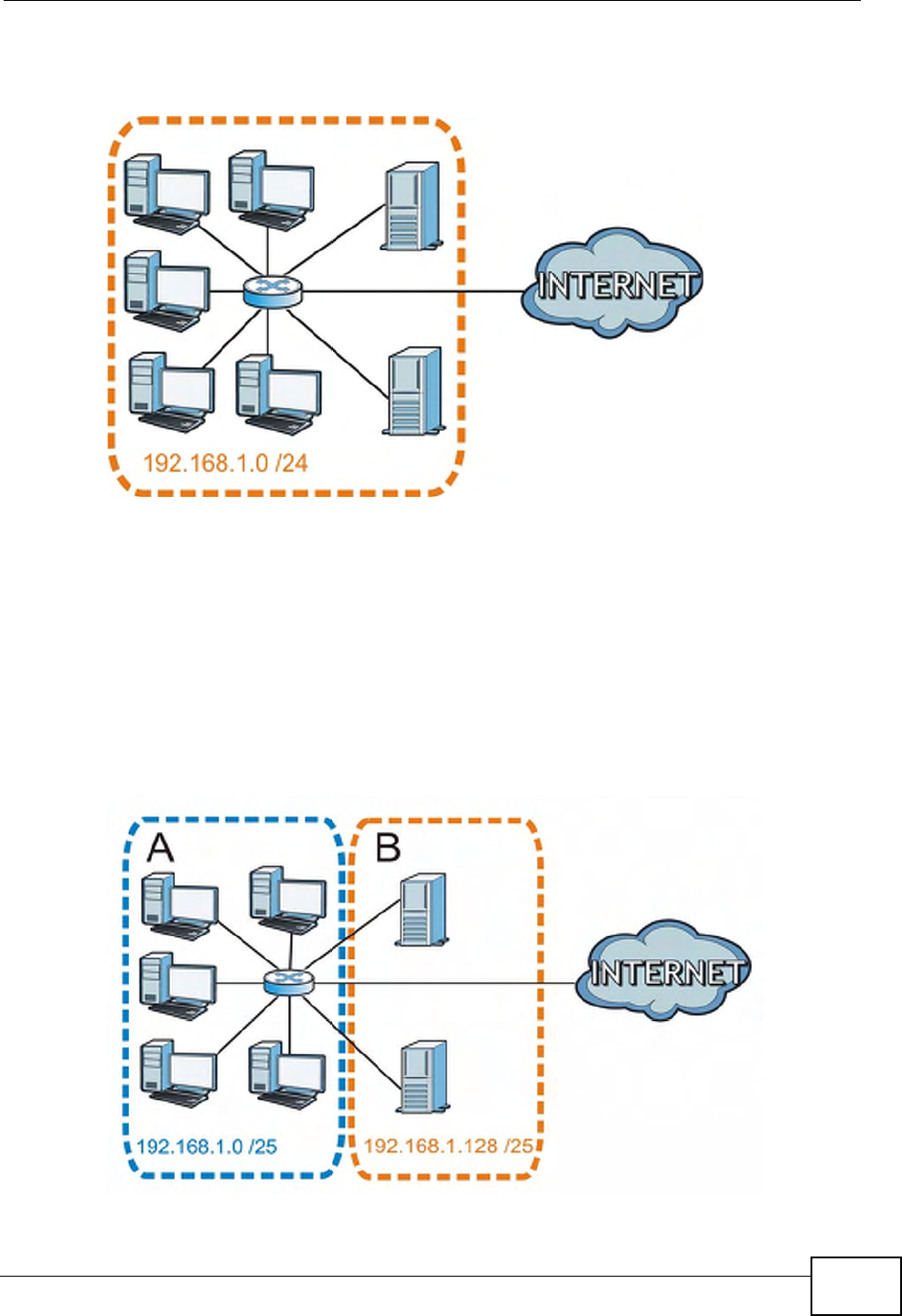
Appendix B IP Addresses and Subnetting
P-660HN-Tx User’s Guide 263
The following figure shows the company network before subnetting.
Figure 144 Subnetting Example: Before Subnetting
You can “borrow” one of the host ID bits to divide the network 192.168.1.0 into
two separate sub-networks. The subnet mask is now 25 bits (255.255.255.128 or
/25).
The “borrowed” host ID bit can have a value of either 0 or 1, allowing two
subnets; 192.168.1.0 /25 and 192.168.1.128 /25.
The following figure shows the company network after subnetting. There are now
two sub-networks, A and B.
Figure 145 Subnetting Example: After Subnetting
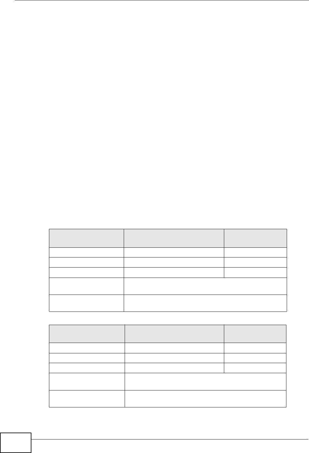
Appendix B IP Addresses and Subnetting
P-660HN-Tx User’s Guide
264
In a 25-bit subnet the host ID has 7 bits, so each sub-network has a maximum of
27 – 2 or 126 possible hosts (a host ID of all zeroes is the subnet’s address itself,
all ones is the subnet’s broadcast address).
192.168.1.0 with mask 255.255.255.128 is subnet A itself, and 192.168.1.127
with mask 255.255.255.128 is its broadcast address. Therefore, the lowest IP
address that can be assigned to an actual host for subnet A is 192.168.1.1 and
the highest is 192.168.1.126.
Similarly, the host ID range for subnet B is 192.168.1.129 to 192.168.1.254.
Example: Four Subnets
The previous example illustrated using a 25-bit subnet mask to divide a 24-bit
address into two subnets. Similarly, to divide a 24-bit address into four subnets,
you need to “borrow” two host ID bits to give four possible combinations (00, 01,
10 and 11). The subnet mask is 26 bits
(11111111.11111111.11111111.11000000) or 255.255.255.192.
Each subnet contains 6 host ID bits, giving 26 - 2 or 62 hosts for each subnet (a
host ID of all zeroes is the subnet itself, all ones is the subnet’s broadcast
address).
Table 85 Subnet 1
IP/SUBNET MASK NETWORK NUMBER LAST OCTET BIT
VALUE
IP Address (Decimal) 192.168.1. 0
IP Address (Binary) 11000000.10101000.00000001. 00000000
Subnet Mask (Binary) 11111111.11111111.11111111. 11000000
Subnet Address:
192.168.1.0
Lowest Host ID: 192.168.1.1
Broadcast Address:
192.168.1.63
Highest Host ID: 192.168.1.62
Table 86 Subnet 2
IP/SUBNET MASK NETWORK NUMBER LAST OCTET BIT
VALUE
IP Address 192.168.1. 64
IP Address (Binary) 11000000.10101000.00000001. 01000000
Subnet Mask (Binary) 11111111.11111111.11111111. 11000000
Subnet Address:
192.168.1.64
Lowest Host ID: 192.168.1.65
Broadcast Address:
192.168.1.127
Highest Host ID: 192.168.1.126
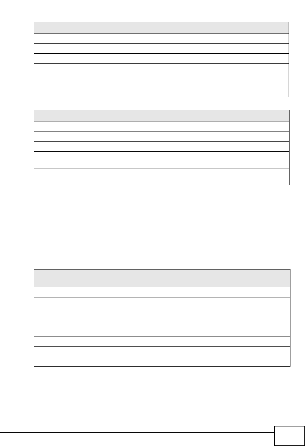
Appendix B IP Addresses and Subnetting
P-660HN-Tx User’s Guide 265
Example: Eight Subnets
Similarly, use a 27-bit mask to create eight subnets (000, 001, 010, 011, 100,
101, 110 and 111).
The following table shows IP address last octet values for each subnet.
Table 87 Subnet 3
IP/SUBNET MASK NETWORK NUMBER LAST OCTET BIT VALUE
IP Address 192.168.1. 128
IP Address (Binary) 11000000.10101000.00000001. 10000000
Subnet Mask (Binary) 11111111.11111111.11111111. 11000000
Subnet Address:
192.168.1.128
Lowest Host ID: 192.168.1.129
Broadcast Address:
192.168.1.191
Highest Host ID: 192.168.1.190
Table 88 Subnet 4
IP/SUBNET MASK NETWORK NUMBER LAST OCTET BIT VALUE
IP Address 192.168.1. 192
IP Address (Binary) 11000000.10101000.00000001. 11000000
Subnet Mask (Binary) 11111111.11111111.11111111. 11000000
Subnet Address:
192.168.1.192
Lowest Host ID: 192.168.1.193
Broadcast Address:
192.168.1.255
Highest Host ID: 192.168.1.254
Table 89 Eight Subnets
SUBNET SUBNET
ADDRESS FIRST ADDRESS LAST
ADDRESS
BROADCAST
ADDRESS
1 0 1 30 31
232 33 62 63
364 65 94 95
496 97 126 127
5128 129 158 159
6160 161 190 191
7192 193 222 223
8224 225 254 255
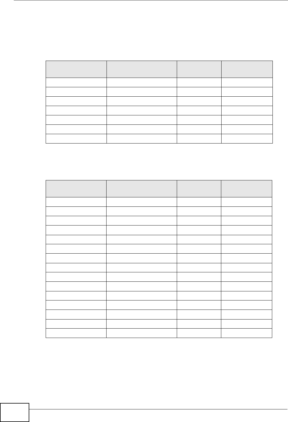
Appendix B IP Addresses and Subnetting
P-660HN-Tx User’s Guide
266
Subnet Planning
The following table is a summary for subnet planning on a network with a 24-bit
network number.
The following table is a summary for subnet planning on a network with a 16-bit
network number.
Configuring IP Addresses
Where you obtain your network number depends on your particular situation. If
the ISP or your network administrator assigns you a block of registered IP
Table 90 24-bit Network Number Subnet Planning
NO. “BORROWED”
HOST BITS SUBNET MASK NO. SUBNETS NO. HOSTS PER
SUBNET
1255.255.255.128 (/25) 2126
2255.255.255.192 (/26) 462
3255.255.255.224 (/27) 830
4255.255.255.240 (/28) 16 14
5255.255.255.248 (/29) 32 6
6255.255.255.252 (/30) 64 2
7255.255.255.254 (/31) 128 1
Table 91 16-bit Network Number Subnet Planning
NO. “BORROWED”
HOST BITS SUBNET MASK NO. SUBNETS NO. HOSTS PER
SUBNET
1255.255.128.0 (/17) 232766
2255.255.192.0 (/18) 416382
3255.255.224.0 (/19) 88190
4255.255.240.0 (/20) 16 4094
5255.255.248.0 (/21) 32 2046
6255.255.252.0 (/22) 64 1022
7255.255.254.0 (/23) 128 510
8255.255.255.0 (/24) 256 254
9255.255.255.128 (/25) 512 126
10 255.255.255.192 (/26) 1024 62
11 255.255.255.224 (/27) 2048 30
12 255.255.255.240 (/28) 4096 14
13 255.255.255.248 (/29) 8192 6
14 255.255.255.252 (/30) 16384 2
15 255.255.255.254 (/31) 32768 1

Appendix B IP Addresses and Subnetting
P-660HN-Tx User’s Guide 267
addresses, follow their instructions in selecting the IP addresses and the subnet
mask.
If the ISP did not explicitly give you an IP network number, then most likely you
have a single user account and the ISP will assign you a dynamic IP address when
the connection is established. If this is the case, it is recommended that you select
a network number from 192.168.0.0 to 192.168.255.0. The Internet Assigned
Number Authority (IANA) reserved this block of addresses specifically for private
use; please do not use any other number unless you are told otherwise. You must
also enable Network Address Translation (NAT) on the ZyXEL Device.
Once you have decided on the network number, pick an IP address for your ZyXEL
Device that is easy to remember (for instance, 192.168.1.1) but make sure that
no other device on your network is using that IP address.
The subnet mask specifies the network number portion of an IP address. Your
ZyXEL Device will compute the subnet mask automatically based on the IP
address that you entered. You don't need to change the subnet mask computed by
the ZyXEL Device unless you are instructed to do otherwise.
Private IP Addresses
Every machine on the Internet must have a unique address. If your networks are
isolated from the Internet (running only between two branch offices, for example)
you can assign any IP addresses to the hosts without problems. However, the
Internet Assigned Numbers Authority (IANA) has reserved the following three
blocks of IP addresses specifically for private networks:
• 10.0.0.0 — 10.255.255.255
• 172.16.0.0 — 172.31.255.255
• 192.168.0.0 — 192.168.255.255
You can obtain your IP address from the IANA, from an ISP, or it can be assigned
from a private network. If you belong to a small organization and your Internet
access is through an ISP, the ISP can provide you with the Internet addresses for
your local networks. On the other hand, if you are part of a much larger
organization, you should consult your network administrator for the appropriate IP
addresses.
Regardless of your particular situation, do not create an arbitrary IP address;
always follow the guidelines above. For more information on address assignment,
please refer to RFC 1597, Address Allocation for Private Internets and RFC 1466,
Guidelines for Management of IP Address Space.

Appendix B IP Addresses and Subnetting
P-660HN-Tx User’s Guide
268
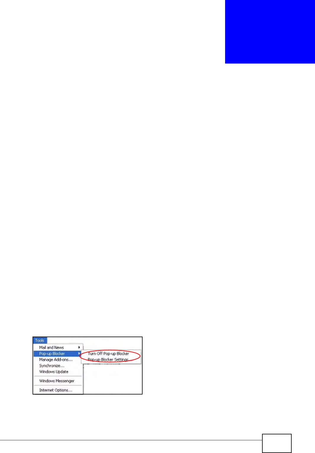
P-660HN-Tx User’s Guide 269
APPENDIX C
Pop-up Windows, JavaScripts
and Java Permissions
In order to use the web configurator you need to allow:
• Web browser pop-up windows from your device.
• JavaScripts (enabled by default).
• Java permissions (enabled by default).
Note: Internet Explorer 6 screens are used here. Screens for other Internet Explorer
versions may vary.
Internet Explorer Pop-up Blockers
You may have to disable pop-up blocking to log into your device.
Either disable pop-up blocking (enabled by default in Windows XP SP (Service
Pack) 2) or allow pop-up blocking and create an exception for your device’s IP
address.
Disable Pop-up Blockers
1In Internet Explorer, select Tools, Pop-up Blocker and then select Turn Off
Pop-up Blocker.
Figure 146 Pop-up Blocker
You can also check if pop-up blocking is disabled in the Pop-up Blocker section in
the Privacy tab.

Appendix C Pop-up Windows, JavaScripts and Java Permissions
P-660HN-Tx User’s Guide
270
1In Internet Explorer, select Tools, Internet Options, Privacy.
2Clear the Block pop-ups check box in the Pop-up Blocker section of the screen.
This disables any web pop-up blockers you may have enabled.
Figure 147 Internet Options: Privacy
3Click Apply to save this setting.
Enable Pop-up Blockers with Exceptions
Alternatively, if you only want to allow pop-up windows from your device, see the
following steps.
1In Internet Explorer, select Tools, Internet Options and then the Privacy tab.
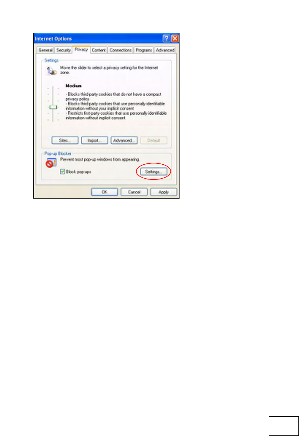
Appendix C Pop-up Windows, JavaScripts and Java Permissions
P-660HN-Tx User’s Guide 271
2Select Settings…to open the Pop-up Blocker Settings screen.
Figure 148 Internet Options: Privacy
3Type the IP address of your device (the web page that you do not want to have
blocked) with the prefix “http://”. For example, http://192.168.167.1.
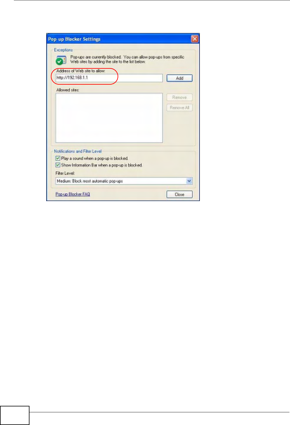
Appendix C Pop-up Windows, JavaScripts and Java Permissions
P-660HN-Tx User’s Guide
272
4Click Add to move the IP address to the list of Allowed sites.
Figure 149 Pop-up Blocker Settings
5Click Close to return to the Privacy screen.
6Click Apply to save this setting.
JavaScripts
If pages of the web configurator do not display properly in Internet Explorer, check
that JavaScripts are allowed.
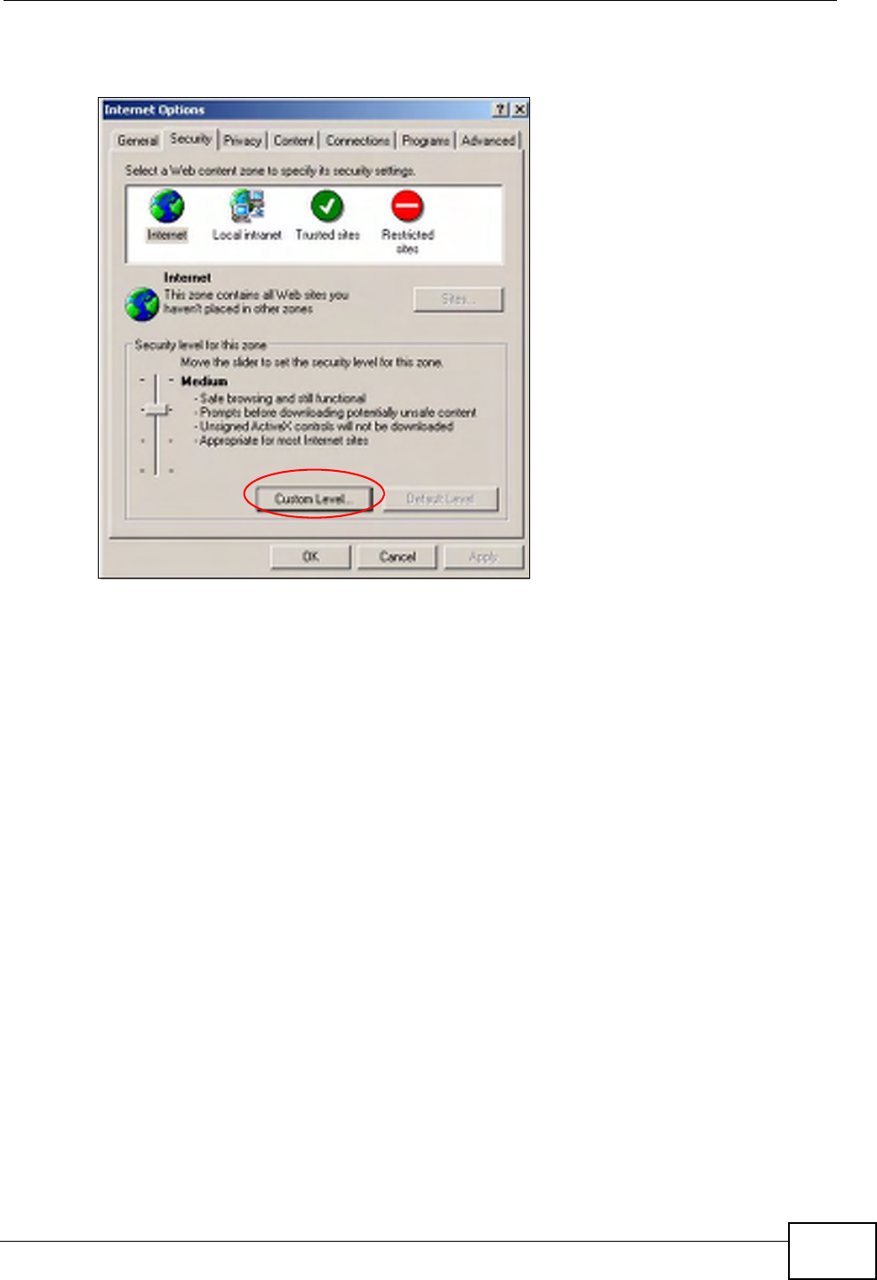
Appendix C Pop-up Windows, JavaScripts and Java Permissions
P-660HN-Tx User’s Guide 273
1In Internet Explorer, click Tools, Internet Options and then the Security tab.
Figure 150 Internet Options: Security
2Click the Custom Level... button.
3Scroll down to Scripting.
4Under Active scripting make sure that Enable is selected (the default).
5Under Scripting of Java applets make sure that Enable is selected (the
default).
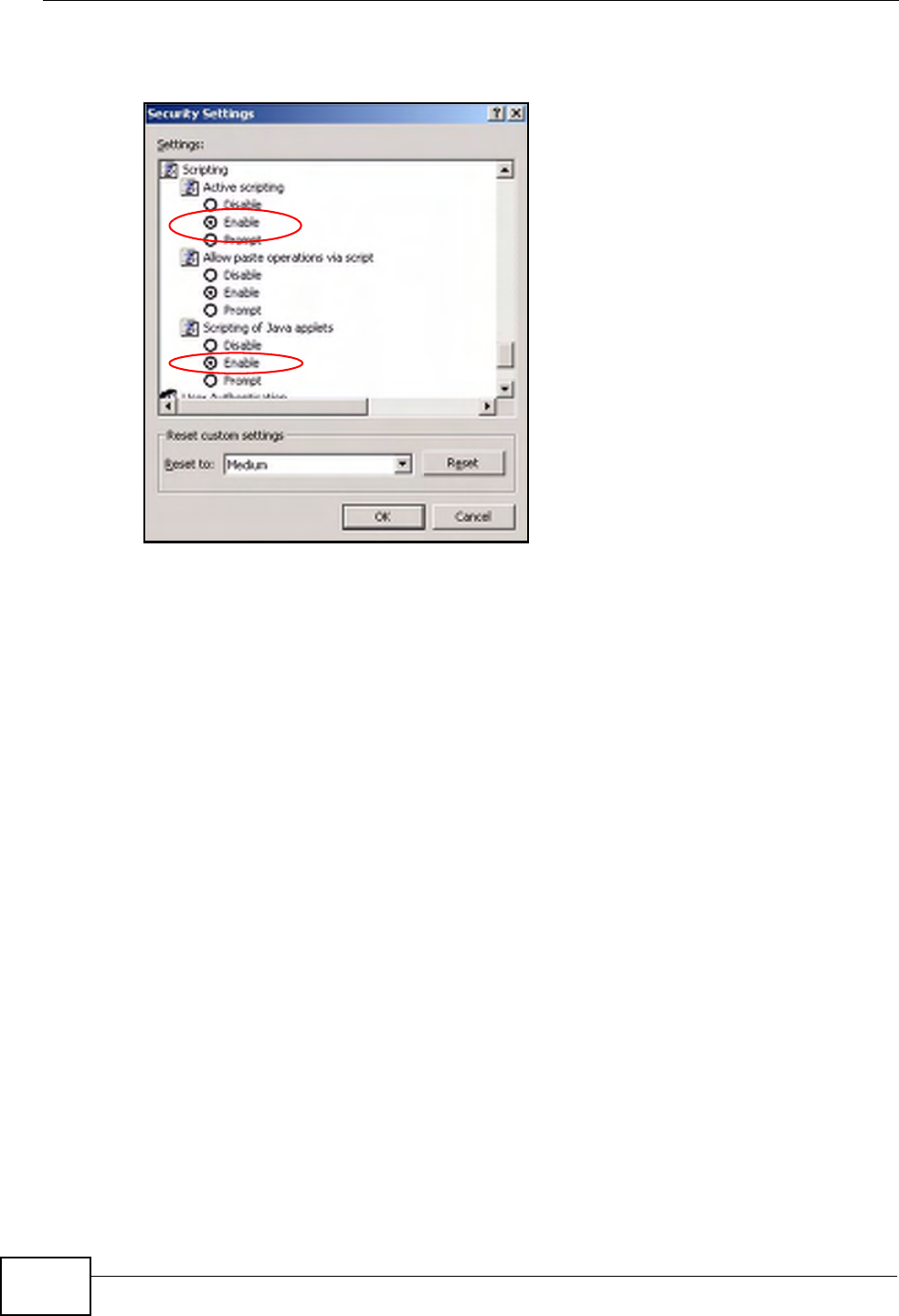
Appendix C Pop-up Windows, JavaScripts and Java Permissions
P-660HN-Tx User’s Guide
274
6Click OK to close the window.
Figure 151 Security Settings - Java Scripting
Java Permissions
1From Internet Explorer, click Tools, Internet Options and then the Security
tab.
2Click the Custom Level... button.
3Scroll down to Microsoft VM.
4Under Java permissions make sure that a safety level is selected.
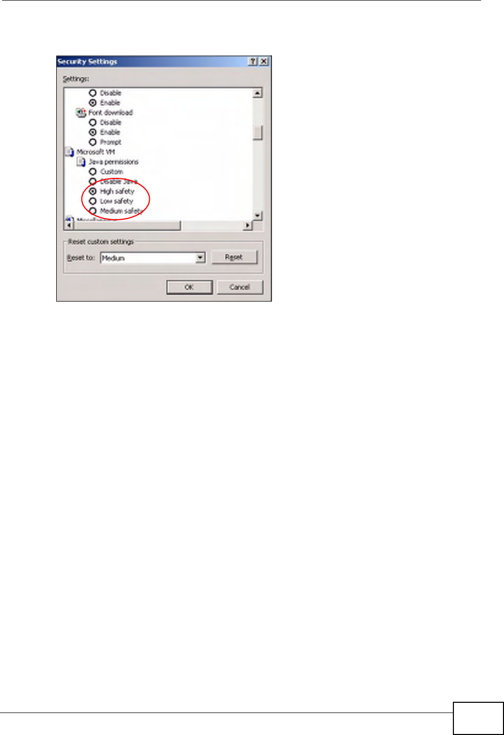
Appendix C Pop-up Windows, JavaScripts and Java Permissions
P-660HN-Tx User’s Guide 275
5Click OK to close the window.
Figure 152 Security Settings - Java
JAVA (Sun)
1From Internet Explorer, click Tools, Internet Options and then the Advanced
tab.
2Make sure that Use Java 2 for <applet> under Java (Sun) is selected.
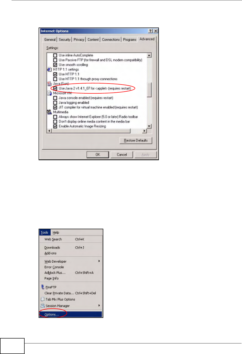
Appendix C Pop-up Windows, JavaScripts and Java Permissions
P-660HN-Tx User’s Guide
276
3Click OK to close the window.
Figure 153 Java (Sun)
Mozilla Firefox
Mozilla Firefox 2.0 screens are used here. Screens for other versions may vary.
You can enable Java, Javascripts and pop-ups in one screen. Click Tools, then
click Options in the screen that appears.
Figure 154 Mozilla Firefox: Tools > Options
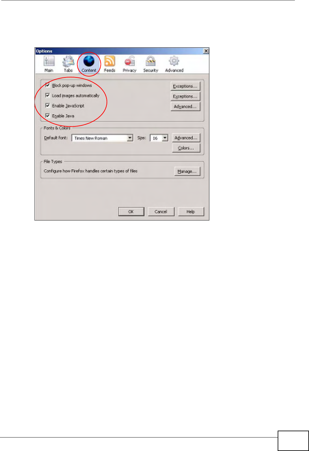
Appendix C Pop-up Windows, JavaScripts and Java Permissions
P-660HN-Tx User’s Guide 277
Click Content.to show the screen below. Select the check boxes as shown in the
following screen.
Figure 155 Mozilla Firefox Content Security

Appendix C Pop-up Windows, JavaScripts and Java Permissions
P-660HN-Tx User’s Guide
278
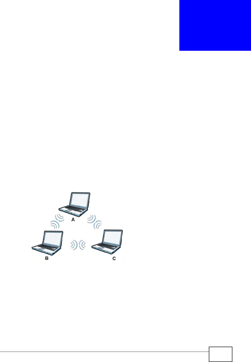
P-660HN-Tx User’s Guide 279
APPENDIX D
Wireless LANs
Wireless LAN Topologies
This section discusses ad-hoc and infrastructure wireless LAN topologies.
Ad-hoc Wireless LAN Configuration
The simplest WLAN configuration is an independent (Ad-hoc) WLAN that connects
a set of computers with wireless adapters (A, B, C). Any time two or more wireless
adapters are within range of each other, they can set up an independent network,
which is commonly referred to as an ad-hoc network or Independent Basic Service
Set (IBSS). The following diagram shows an example of notebook computers
using wireless adapters to form an ad-hoc wireless LAN.
Figure 156 Peer-to-Peer Communication in an Ad-hoc Network
BSS
A Basic Service Set (BSS) exists when all communications between wireless
clients or between a wireless client and a wired network client go through one
access point (AP).
Intra-BSS traffic is traffic between wireless clients in the BSS. When Intra-BSS is
enabled, wireless client A and B can access the wired network and communicate
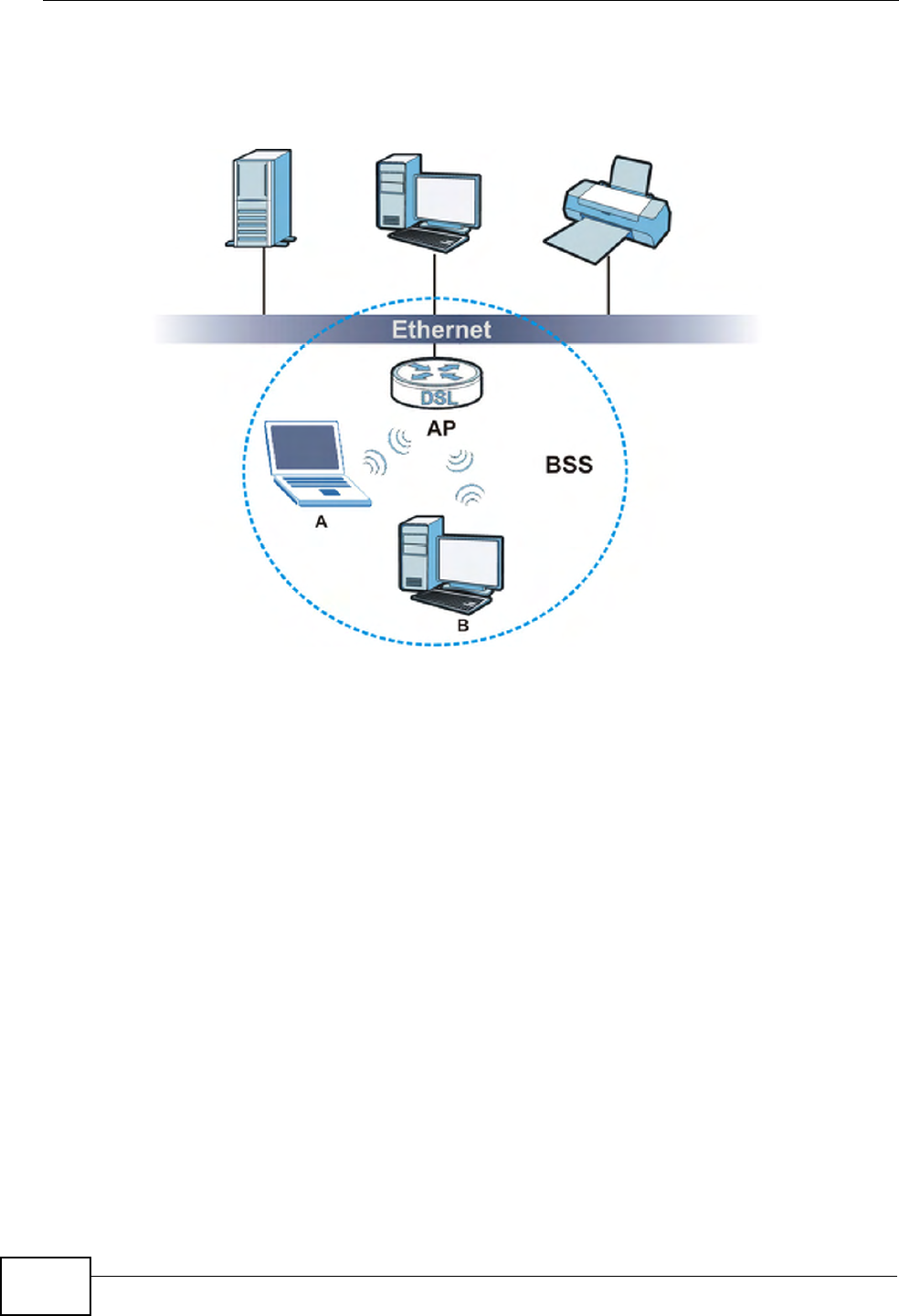
Appendix D Wireless LANs
P-660HN-Tx User’s Guide
280
with each other. When Intra-BSS is disabled, wireless client A and B can still
access the wired network but cannot communicate with each other.
Figure 157 Basic Service Set
ESS
An Extended Service Set (ESS) consists of a series of overlapping BSSs, each
containing an access point, with each access point connected together by a wired
network. This wired connection between APs is called a Distribution System (DS).
This type of wireless LAN topology is called an Infrastructure WLAN. The Access
Points not only provide communication with the wired network but also mediate
wireless network traffic in the immediate neighborhood.
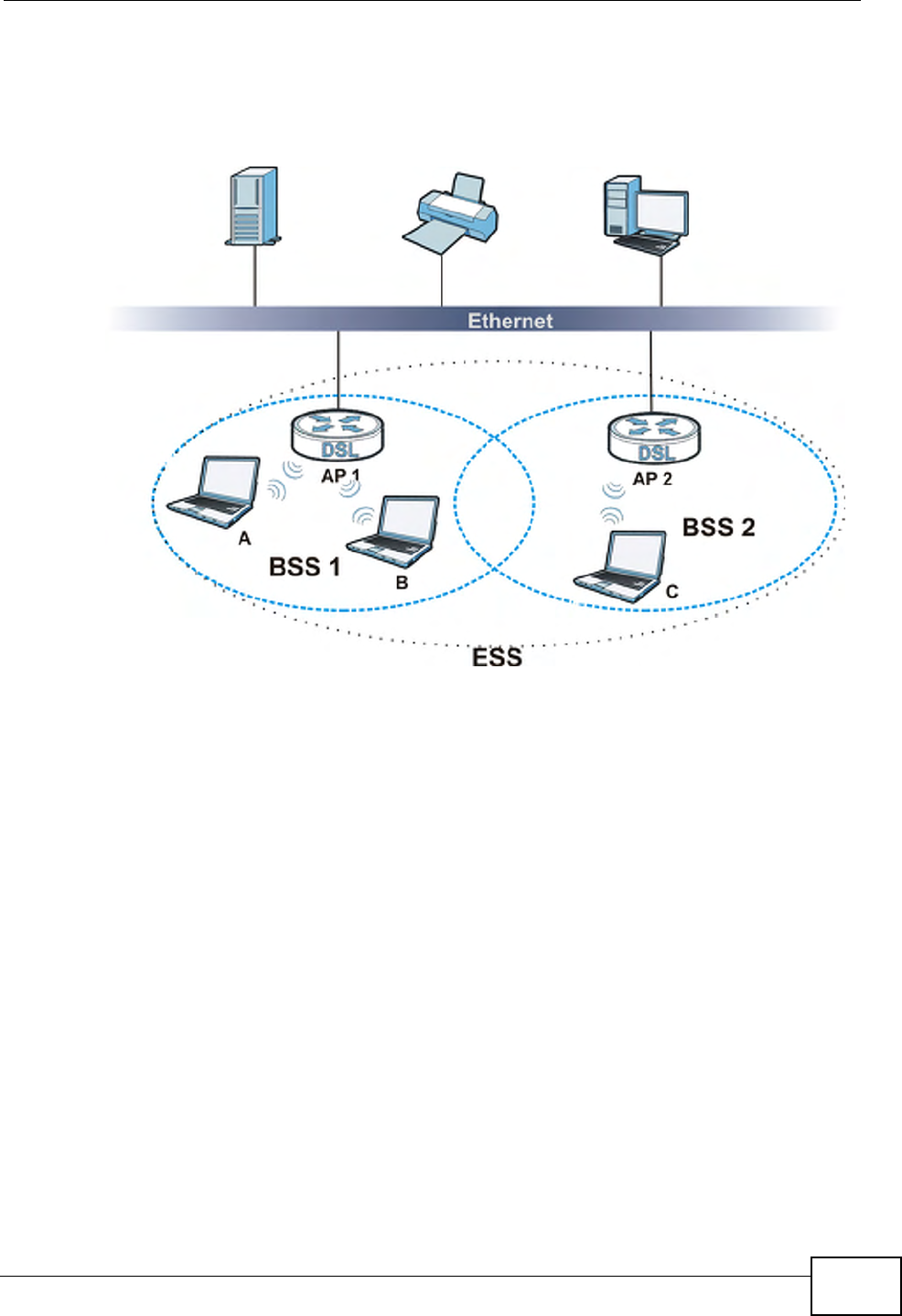
Appendix D Wireless LANs
P-660HN-Tx User’s Guide 281
An ESSID (ESS IDentification) uniquely identifies each ESS. All access points and
their associated wireless clients within the same ESS must have the same ESSID
in order to communicate.
Figure 158 Infrastructure WLAN
Channel
A channel is the radio frequency(ies) used by wireless devices to transmit and
receive data. Channels available depend on your geographical area. You may have
a choice of channels (for your region) so you should use a channel different from
an adjacent AP (access point) to reduce interference. Interference occurs when
radio signals from different access points overlap causing interference and
degrading performance.
Adjacent channels partially overlap however. To avoid interference due to overlap,
your AP should be on a channel at least five channels away from a channel that an
adjacent AP is using. For example, if your region has 11 channels and an adjacent
AP is using channel 1, then you need to select a channel between 6 or 11.
RTS/CTS
A hidden node occurs when two stations are within range of the same access
point, but are not within range of each other. The following figure illustrates a
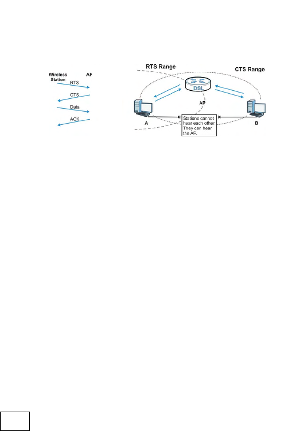
Appendix D Wireless LANs
P-660HN-Tx User’s Guide
282
hidden node. Both stations (STA) are within range of the access point (AP) or
wireless gateway, but out-of-range of each other, so they cannot "hear" each
other, that is they do not know if the channel is currently being used. Therefore,
they are considered hidden from each other.
Figure 159 RTS/CTS
When station A sends data to the AP, it might not know that the station B is
already using the channel. If these two stations send data at the same time,
collisions may occur when both sets of data arrive at the AP at the same time,
resulting in a loss of messages for both stations.
RTS/CTS is designed to prevent collisions due to hidden nodes. An RTS/CTS
defines the biggest size data frame you can send before an RTS (Request To
Send)/CTS (Clear to Send) handshake is invoked.
When a data frame exceeds the RTS/CTS value you set (between 0 to 2432
bytes), the station that wants to transmit this frame must first send an RTS
(Request To Send) message to the AP for permission to send it. The AP then
responds with a CTS (Clear to Send) message to all other stations within its range
to notify them to defer their transmission. It also reserves and confirms with the
requesting station the time frame for the requested transmission.
Stations can send frames smaller than the specified RTS/CTS directly to the AP
without the RTS (Request To Send)/CTS (Clear to Send) handshake.
You should only configure RTS/CTS if the possibility of hidden nodes exists on
your network and the "cost" of resending large frames is more than the extra
network overhead involved in the RTS (Request To Send)/CTS (Clear to Send)
handshake.
If the RTS/CTS value is greater than the Fragmentation Threshold value (see
next), then the RTS (Request To Send)/CTS (Clear to Send) handshake will never
occur as data frames will be fragmented before they reach RTS/CTS size.
Note: Enabling the RTS Threshold causes redundant network overhead that could
negatively affect the throughput performance instead of providing a remedy.

Appendix D Wireless LANs
P-660HN-Tx User’s Guide 283
Fragmentation Threshold
A Fragmentation Threshold is the maximum data fragment size (between 256
and 2432 bytes) that can be sent in the wireless network before the AP will
fragment the packet into smaller data frames.
A large Fragmentation Threshold is recommended for networks not prone to
interference while you should set a smaller threshold for busy networks or
networks that are prone to interference.
If the Fragmentation Threshold value is smaller than the RTS/CTS value (see
previously) you set then the RTS (Request To Send)/CTS (Clear to Send)
handshake will never occur as data frames will be fragmented before they reach
RTS/CTS size.
Preamble Type
Preamble is used to signal that data is coming to the receiver. Short and long refer
to the length of the synchronization field in a packet.
Short preamble increases performance as less time sending preamble means
more time for sending data. All IEEE 802.11 compliant wireless adapters support
long preamble, but not all support short preamble.
Use long preamble if you are unsure what preamble mode other wireless devices
on the network support, and to provide more reliable communications in busy
wireless networks.
Use short preamble if you are sure all wireless devices on the network support it,
and to provide more efficient communications.
Use the dynamic setting to automatically use short preamble when all wireless
devices on the network support it, otherwise the ZyXEL Device uses long
preamble.
Note: The wireless devices MUST use the same preamble mode in order to
communicate.
IEEE 802.11g Wireless LAN
IEEE 802.11g is fully compatible with the IEEE 802.11b standard. This means an
IEEE 802.11b adapter can interface directly with an IEEE 802.11g access point
(and vice versa) at 11 Mbps or lower depending on range. IEEE 802.11g has
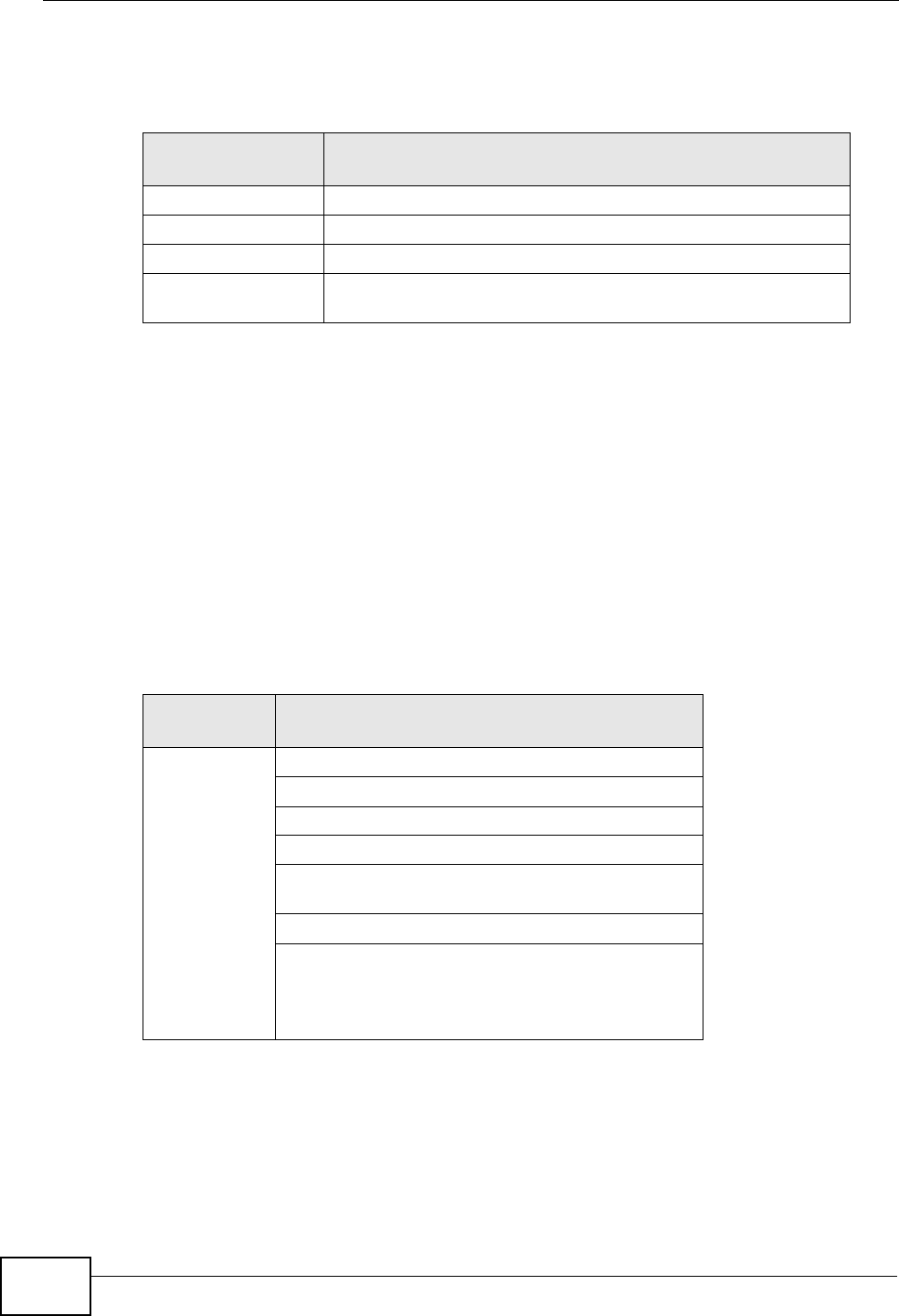
Appendix D Wireless LANs
P-660HN-Tx User’s Guide
284
several intermediate rate steps between the maximum and minimum data rates.
The IEEE 802.11g data rate and modulation are as follows:
Wireless Security Overview
Wireless security is vital to your network to protect wireless communication
between wireless clients, access points and the wired network.
Wireless security methods available on the ZyXEL Device are data encryption,
wireless client authentication, restricting access by device MAC address and hiding
the ZyXEL Device identity.
The following figure shows the relative effectiveness of these wireless security
methods available on your ZyXEL Device.
Note: You must enable the same wireless security settings on the ZyXEL Device and
on all wireless clients that you want to associate with it.
Table 92 IEEE 802.11g
DATA RATE
(MBPS) MODULATION
1 DBPSK (Differential Binary Phase Shift Keyed)
2 DQPSK (Differential Quadrature Phase Shift Keying)
5.5 / 11 CCK (Complementary Code Keying)
6/9/12/18/24/36/
48/54
OFDM (Orthogonal Frequency Division Multiplexing)
Table 93 Wireless Security Levels
SECURITY
LEVEL SECURITY TYPE
Least
Secure
Most Secure
Unique SSID (Default)
Unique SSID with Hide SSID Enabled
MAC Address Filtering
WEP Encryption
IEEE802.1x EAP with RADIUS Server
Authentication
Wi-Fi Protected Access (WPA)
WPA2

Appendix D Wireless LANs
P-660HN-Tx User’s Guide 285
IEEE 802.1x
In June 2001, the IEEE 802.1x standard was designed to extend the features of
IEEE 802.11 to support extended authentication as well as providing additional
accounting and control features. It is supported by Windows XP and a number of
network devices. Some advantages of IEEE 802.1x are:
• User based identification that allows for roaming.
• Support for RADIUS (Remote Authentication Dial In User Service, RFC 2138,
2139) for centralized user profile and accounting management on a network
RADIUS server.
• Support for EAP (Extensible Authentication Protocol, RFC 2486) that allows
additional authentication methods to be deployed with no changes to the access
point or the wireless clients.
RADIUS
RADIUS is based on a client-server model that supports authentication,
authorization and accounting. The access point is the client and the server is the
RADIUS server. The RADIUS server handles the following tasks:
• Authentication
Determines the identity of the users.
• Authorization
Determines the network services available to authenticated users once they are
connected to the network.
•Accounting
Keeps track of the client’s network activity.
RADIUS is a simple package exchange in which your AP acts as a message relay
between the wireless client and the network RADIUS server.
Types of RADIUS Messages
The following types of RADIUS messages are exchanged between the access point
and the RADIUS server for user authentication:
• Access-Request
Sent by an access point requesting authentication.
• Access-Reject
Sent by a RADIUS server rejecting access.
• Access-Accept
Sent by a RADIUS server allowing access.

Appendix D Wireless LANs
P-660HN-Tx User’s Guide
286
•Access-Challenge
Sent by a RADIUS server requesting more information in order to allow access.
The access point sends a proper response from the user and then sends another
Access-Request message.
The following types of RADIUS messages are exchanged between the access point
and the RADIUS server for user accounting:
•Accounting-Request
Sent by the access point requesting accounting.
• Accounting-Response
Sent by the RADIUS server to indicate that it has started or stopped accounting.
In order to ensure network security, the access point and the RADIUS server use a
shared secret key, which is a password, they both know. The key is not sent over
the network. In addition to the shared key, password information exchanged is
also encrypted to protect the network from unauthorized access.
Types of EAP Authentication
This section discusses some popular authentication types: EAP-MD5, EAP-TLS,
EAP-TTLS, PEAP and LEAP. Your wireless LAN device may not support all
authentication types.
EAP (Extensible Authentication Protocol) is an authentication protocol that runs on
top of the IEEE 802.1x transport mechanism in order to support multiple types of
user authentication. By using EAP to interact with an EAP-compatible RADIUS
server, an access point helps a wireless station and a RADIUS server perform
authentication.
The type of authentication you use depends on the RADIUS server and an
intermediary AP(s) that supports IEEE 802.1x.
For EAP-TLS authentication type, you must first have a wired connection to the
network and obtain the certificate(s) from a certificate authority (CA). A certificate
(also called digital IDs) can be used to authenticate users and a CA issues
certificates and guarantees the identity of each certificate owner.
EAP-MD5 (Message-Digest Algorithm 5)
MD5 authentication is the simplest one-way authentication method. The
authentication server sends a challenge to the wireless client. The wireless client
‘proves’ that it knows the password by encrypting the password with the challenge
and sends back the information. Password is not sent in plain text.

Appendix D Wireless LANs
P-660HN-Tx User’s Guide 287
However, MD5 authentication has some weaknesses. Since the authentication
server needs to get the plaintext passwords, the passwords must be stored. Thus
someone other than the authentication server may access the password file. In
addition, it is possible to impersonate an authentication server as MD5
authentication method does not perform mutual authentication. Finally, MD5
authentication method does not support data encryption with dynamic session
key. You must configure WEP encryption keys for data encryption.
EAP-TLS (Transport Layer Security)
With EAP-TLS, digital certifications are needed by both the server and the wireless
clients for mutual authentication. The server presents a certificate to the client.
After validating the identity of the server, the client sends a different certificate to
the server. The exchange of certificates is done in the open before a secured
tunnel is created. This makes user identity vulnerable to passive attacks. A digital
certificate is an electronic ID card that authenticates the sender’s identity.
However, to implement EAP-TLS, you need a Certificate Authority (CA) to handle
certificates, which imposes a management overhead.
EAP-TTLS (Tunneled Transport Layer Service)
EAP-TTLS is an extension of the EAP-TLS authentication that uses certificates for
only the server-side authentications to establish a secure connection. Client
authentication is then done by sending username and password through the
secure connection, thus client identity is protected. For client authentication, EAP-
TTLS supports EAP methods and legacy authentication methods such as PAP,
CHAP, MS-CHAP and MS-CHAP v2.
PEAP (Protected EAP)
Like EAP-TTLS, server-side certificate authentication is used to establish a secure
connection, then use simple username and password methods through the
secured connection to authenticate the clients, thus hiding client identity.
However, PEAP only supports EAP methods, such as EAP-MD5, EAP-MSCHAPv2
and EAP-GTC (EAP-Generic Token Card), for client authentication. EAP-GTC is
implemented only by Cisco.
LEAP
LEAP (Lightweight Extensible Authentication Protocol) is a Cisco implementation of
IEEE 802.1x.
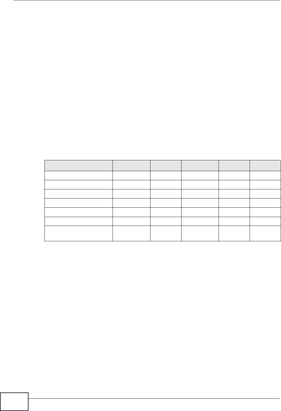
Appendix D Wireless LANs
P-660HN-Tx User’s Guide
288
Dynamic WEP Key Exchange
The AP maps a unique key that is generated with the RADIUS server. This key
expires when the wireless connection times out, disconnects or reauthentication
times out. A new WEP key is generated each time reauthentication is performed.
If this feature is enabled, it is not necessary to configure a default encryption key
in the wireless security configuration screen. You may still configure and store
keys, but they will not be used while dynamic WEP is enabled.
Note: EAP-MD5 cannot be used with Dynamic WEP Key Exchange
For added security, certificate-based authentications (EAP-TLS, EAP-TTLS and
PEAP) use dynamic keys for data encryption. They are often deployed in corporate
environments, but for public deployment, a simple user name and password pair
is more practical. The following table is a comparison of the features of
authentication types.
WPA and WPA2
Wi-Fi Protected Access (WPA) is a subset of the IEEE 802.11i standard. WPA2
(IEEE 802.11i) is a wireless security standard that defines stronger encryption,
authentication and key management than WPA.
Key differences between WPA or WPA2 and WEP are improved data encryption and
user authentication.
If both an AP and the wireless clients support WPA2 and you have an external
RADIUS server, use WPA2 for stronger data encryption. If you don't have an
external RADIUS server, you should use WPA2-PSK (WPA2-Pre-Shared Key) that
only requires a single (identical) password entered into each access point, wireless
gateway and wireless client. As long as the passwords match, a wireless client will
be granted access to a WLAN.
Table 94 Comparison of EAP Authentication Types
EAP-MD5 EAP-TLS EAP-TTLS PEAP LEAP
Mutual Authentication No Yes Yes Yes Yes
Certificate – Client No Yes Optional Optional No
Certificate – Server No Yes Yes Yes No
Dynamic Key Exchange No Yes Yes Yes Yes
Credential Integrity None Strong Strong Strong Moderate
Deployment Difficulty Easy Hard Moderate Moderate Moderate
Client Identity
Protection
No No Yes Yes No

Appendix D Wireless LANs
P-660HN-Tx User’s Guide 289
If the AP or the wireless clients do not support WPA2, just use WPA or WPA-PSK
depending on whether you have an external RADIUS server or not.
Select WEP only when the AP and/or wireless clients do not support WPA or WPA2.
WEP is less secure than WPA or WPA2.
Encryption
WPA improves data encryption by using Temporal Key Integrity Protocol (TKIP),
Message Integrity Check (MIC) and IEEE 802.1x. WPA2 also uses TKIP when
required for compatibility reasons, but offers stronger encryption than TKIP with
Advanced Encryption Standard (AES) in the Counter mode with Cipher block
chaining Message authentication code Protocol (CCMP).
TKIP uses 128-bit keys that are dynamically generated and distributed by the
authentication server. AES (Advanced Encryption Standard) is a block cipher that
uses a 256-bit mathematical algorithm called Rijndael. They both include a per-
packet key mixing function, a Message Integrity Check (MIC) named Michael, an
extended initialization vector (IV) with sequencing rules, and a re-keying
mechanism.
WPA and WPA2 regularly change and rotate the encryption keys so that the same
encryption key is never used twice.
The RADIUS server distributes a Pairwise Master Key (PMK) key to the AP that
then sets up a key hierarchy and management system, using the PMK to
dynamically generate unique data encryption keys to encrypt every data packet
that is wirelessly communicated between the AP and the wireless clients. This all
happens in the background automatically.
The Message Integrity Check (MIC) is designed to prevent an attacker from
capturing data packets, altering them and resending them. The MIC provides a
strong mathematical function in which the receiver and the transmitter each
compute and then compare the MIC. If they do not match, it is assumed that the
data has been tampered with and the packet is dropped.
By generating unique data encryption keys for every data packet and by creating
an integrity checking mechanism (MIC), with TKIP and AES it is more difficult to
decrypt data on a Wi-Fi network than WEP and difficult for an intruder to break
into the network.
The encryption mechanisms used for WPA(2) and WPA(2)-PSK are the same. The
only difference between the two is that WPA(2)-PSK uses a simple common
password, instead of user-specific credentials. The common-password approach
makes WPA(2)-PSK susceptible to brute-force password-guessing attacks but it’s
still an improvement over WEP as it employs a consistent, single, alphanumeric
password to derive a PMK which is used to generate unique temporal encryption

Appendix D Wireless LANs
P-660HN-Tx User’s Guide
290
keys. This prevent all wireless devices sharing the same encryption keys. (a
weakness of WEP)
User Authentication
WPA and WPA2 apply IEEE 802.1x and Extensible Authentication Protocol (EAP) to
authenticate wireless clients using an external RADIUS database. WPA2 reduces
the number of key exchange messages from six to four (CCMP 4-way handshake)
and shortens the time required to connect to a network. Other WPA2
authentication features that are different from WPA include key caching and pre-
authentication. These two features are optional and may not be supported in all
wireless devices.
Key caching allows a wireless client to store the PMK it derived through a
successful authentication with an AP. The wireless client uses the PMK when it tries
to connect to the same AP and does not need to go with the authentication
process again.
Pre-authentication enables fast roaming by allowing the wireless client (already
connecting to an AP) to perform IEEE 802.1x authentication with another AP
before connecting to it.
Wireless Client WPA Supplicants
A wireless client supplicant is the software that runs on an operating system
instructing the wireless client how to use WPA. At the time of writing, the most
widely available supplicant is the WPA patch for Windows XP, Funk Software's
Odyssey client.
The Windows XP patch is a free download that adds WPA capability to Windows
XP's built-in "Zero Configuration" wireless client. However, you must run Windows
XP to use it.
WPA(2) with RADIUS Application Example
To set up WPA(2), you need the IP address of the RADIUS server, its port number
(default is 1812), and the RADIUS shared secret. A WPA(2) application example
with an external RADIUS server looks as follows. "A" is the RADIUS server. "DS" is
the distribution system.
1The AP passes the wireless client's authentication request to the RADIUS server.
2The RADIUS server then checks the user's identification against its database and
grants or denies network access accordingly.
3A 256-bit Pairwise Master Key (PMK) is derived from the authentication process by
the RADIUS server and the client.
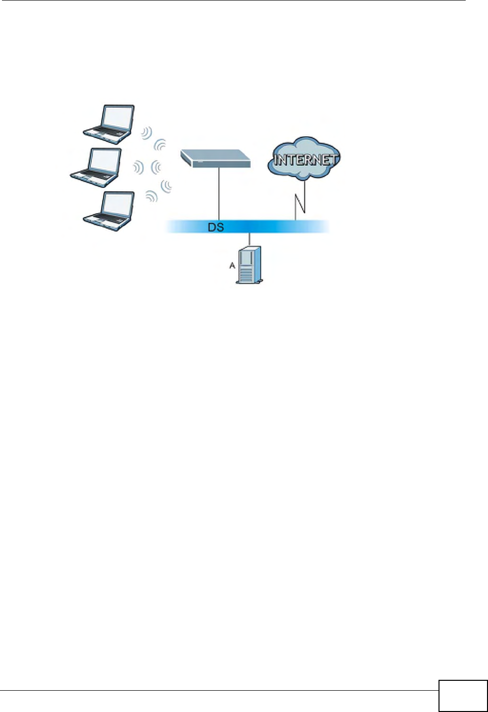
Appendix D Wireless LANs
P-660HN-Tx User’s Guide 291
4The RADIUS server distributes the PMK to the AP. The AP then sets up a key
hierarchy and management system, using the PMK to dynamically generate
unique data encryption keys. The keys are used to encrypt every data packet that
is wirelessly communicated between the AP and the wireless clients.
Figure 160 WPA(2) with RADIUS Application Example
WPA(2)-PSK Application Example
A WPA(2)-PSK application looks as follows.
1First enter identical passwords into the AP and all wireless clients. The Pre-Shared
Key (PSK) must consist of between 8 and 63 ASCII characters or 64 hexadecimal
characters (including spaces and symbols).
2The AP checks each wireless client's password and allows it to join the network
only if the password matches.
3The AP and wireless clients generate a common PMK (Pairwise Master Key). The
key itself is not sent over the network, but is derived from the PSK and the SSID.
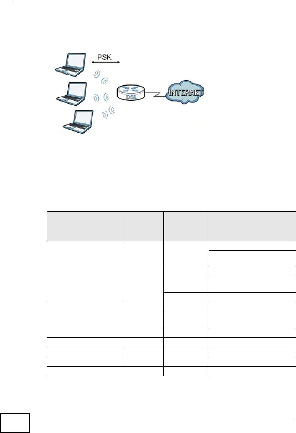
Appendix D Wireless LANs
P-660HN-Tx User’s Guide
292
4The AP and wireless clients use the TKIP or AES encryption process, the PMK and
information exchanged in a handshake to create temporal encryption keys. They
use these keys to encrypt data exchanged between them.
Figure 161 WPA(2)-PSK Authentication
Security Parameters Summary
Refer to this table to see what other security parameters you should configure for
each authentication method or key management protocol type. MAC address
filters are not dependent on how you configure these security features.
Table 95 Wireless Security Relational Matrix
AUTHENTICATION
METHOD/ KEY
MANAGEMENT
PROTOCOL
ENCRYPTIO
N METHOD
ENTER
MANUAL KEY IEEE 802.1X
Open None No Disable
Enable without Dynamic WEP
Key
Open WEP No Enable with Dynamic WEP Key
Yes Enable without Dynamic WEP
Key
Yes Disable
Shared WEP No Enable with Dynamic WEP Key
Yes Enable without Dynamic WEP
Key
Yes Disable
WPA TKIP/AES No Enable
WPA-PSK TKIP/AES Yes Disable
WPA2 TKIP/AES No Enable
WPA2-PSK TKIP/AES Yes Disable

Appendix D Wireless LANs
P-660HN-Tx User’s Guide 293
Antenna Overview
An antenna couples RF signals onto air. A transmitter within a wireless device
sends an RF signal to the antenna, which propagates the signal through the air.
The antenna also operates in reverse by capturing RF signals from the air.
Positioning the antennas properly increases the range and coverage area of a
wireless LAN.
Antenna Characteristics
Frequency
An antenna in the frequency of 2.4GHz (IEEE 802.11b and IEEE 802.11g) or 5GHz
(IEEE 802.11a) is needed to communicate efficiently in a wireless LAN
Radiation Pattern
A radiation pattern is a diagram that allows you to visualize the shape of the
antenna’s coverage area.
Antenna Gain
Antenna gain, measured in dB (decibel), is the increase in coverage within the RF
beam width. Higher antenna gain improves the range of the signal for better
communications.
For an indoor site, each 1 dB increase in antenna gain results in a range increase
of approximately 2.5%. For an unobstructed outdoor site, each 1dB increase in
gain results in a range increase of approximately 5%. Actual results may vary
depending on the network environment.
Antenna gain is sometimes specified in dBi, which is how much the antenna
increases the signal power compared to using an isotropic antenna. An isotropic
antenna is a theoretical perfect antenna that sends out radio signals equally well
in all directions. dBi represents the true gain that the antenna provides.
Types of Antennas for WLAN
There are two types of antennas used for wireless LAN applications.

Appendix D Wireless LANs
P-660HN-Tx User’s Guide
294
•Omni-directional antennas send the RF signal out in all directions on a horizontal
plane. The coverage area is torus-shaped (like a donut) which makes these
antennas ideal for a room environment. With a wide coverage area, it is possible
to make circular overlapping coverage areas with multiple access points.
• Directional antennas concentrate the RF signal in a beam, like a flashlight does
with the light from its bulb. The angle of the beam determines the width of the
coverage pattern. Angles typically range from 20 degrees (very directional) to
120 degrees (less directional). Directional antennas are ideal for hallways and
outdoor point-to-point applications.
Positioning Antennas
In general, antennas should be mounted as high as practically possible and free of
obstructions. In point-to–point application, position both antennas at the same
height and in a direct line of sight to each other to attain the best performance.
For omni-directional antennas mounted on a table, desk, and so on, point the
antenna up. For omni-directional antennas mounted on a wall or ceiling, point the
antenna down. For a single AP application, place omni-directional antennas as
close to the center of the coverage area as possible.
For directional antennas, point the antenna in the direction of the desired
coverage area.

P-660HN-Tx User’s Guide 295
APPENDIX E
IPv6
Overview
IPv6 (Internet Protocol version 6), is designed to enhance IP address size and
features. The increase in IPv6 address size to 128 bits (from the 32-bit IPv4
address) allows up to 3.4 x 1038 IP addresses.
IPv6 Addressing
The 128-bit IPv6 address is written as eight 16-bit hexadecimal blocks separated
by colons (:). This is an example IPv6 address
2001:0db8:1a2b:0015:0000:0000:1a2f:0000.
IPv6 addresses can be abbreviated in two ways:
• Leading zeros in a block can be omitted. So
2001:0db8:1a2b:0015:0000:0000:1a2f:0000 can be written as
2001:db8:1a2b:15:0:0:1a2f:0.
• Any number of consecutive blocks of zeros can be replaced by a double colon. A
double colon can only appear once in an IPv6 address. So
2001:0db8:0000:0000:1a2f:0000:0000:0015 can be written as
2001:0db8::1a2f:0000:0000:0015, 2001:0db8:0000:0000:1a2f::0015,
2001:db8::1a2f:0:0:15 or 2001:db8:0:0:1a2f::15.
Prefix and Prefix Length
Similar to an IPv4 subnet mask, IPv6 uses an address prefix to represent the
network address. An IPv6 prefix length specifies how many most significant bits
(start from the left) in the address compose the network address. The prefix
length is written as “/x” where x is a number. For example,
2001:db8:1a2b:15::1a2f:0/32
means that the first 32 bits (2001:db8) is the subnet prefix.
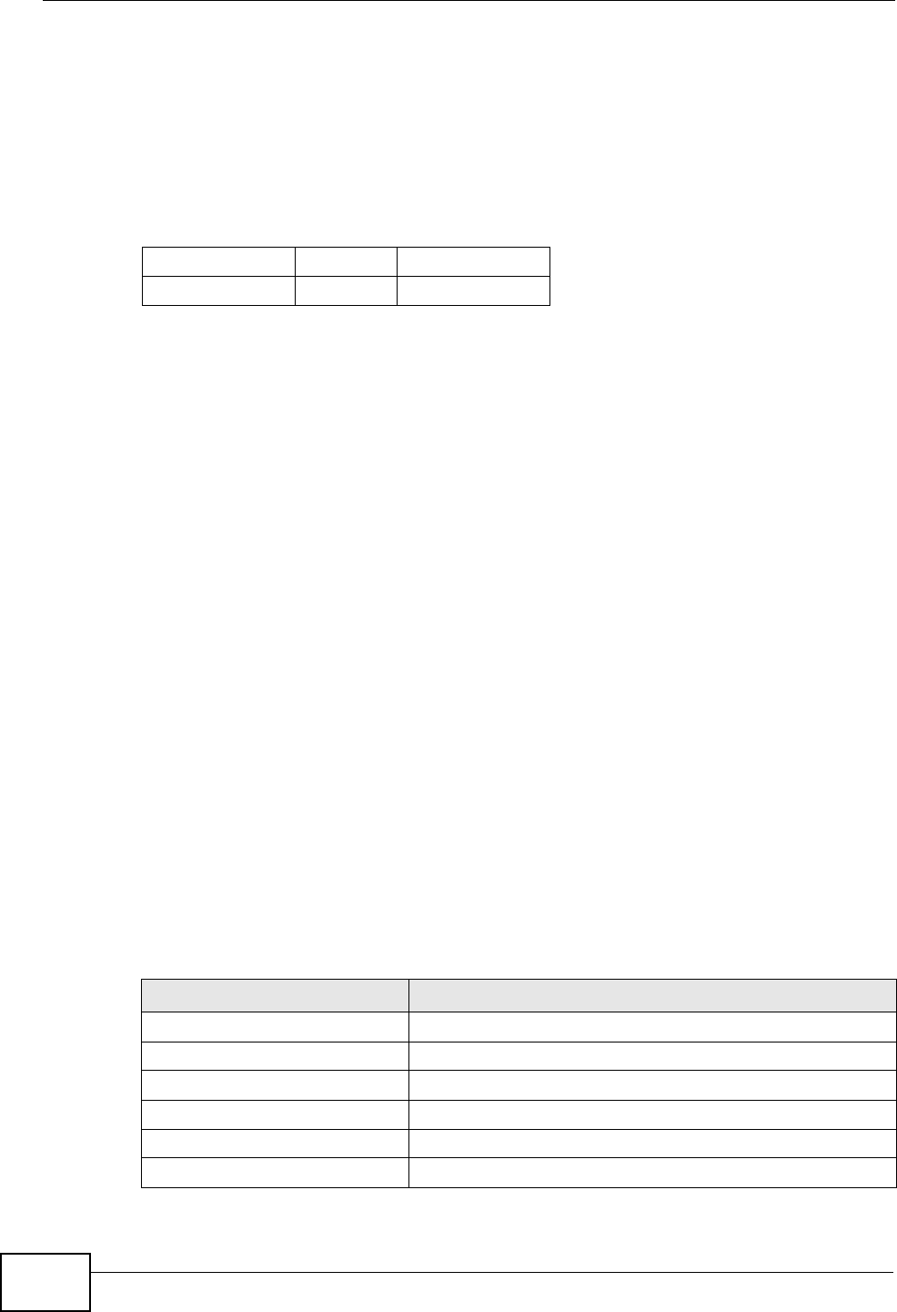
Appendix E IPv6
P-660HN-Tx User’s Guide
296
Link-local Address
A link-local address uniquely identifies a device on the local network (the LAN). It
is similar to a “private IP address” in IPv4. You can have the same link-local
address on multiple interfaces on a device. A link-local unicast address has a
predefined prefix of fe80::/10. The link-local unicast address format is as follows.
Table 96 Link-local Unicast Address Format
Global Address
A global address uniquely identifies a device on the Internet. It is similar to a
“public IP address” in IPv4. A global unicast address starts with a 2 or 3.
Unspecified Address
An unspecified address (0:0:0:0:0:0:0:0 or ::) is used as the source address
when a device does not have its own address. It is similar to “0.0.0.0” in IPv4.
Loopback Address
A loopback address (0:0:0:0:0:0:0:1 or ::1) allows a host to send packets to
itself. It is similar to “127.0.0.1” in IPv4.
Multicast Address
In IPv6, multicast addresses provide the same functionality as IPv4 broadcast
addresses. Broadcasting is not supported in IPv6. A multicast address allows a
host to send packets to all hosts in a multicast group.
Multicast scope allows you to determine the size of the multicast group. A
multicast address has a predefined prefix of ff00::/8. The following table describes
some of the predefined multicast addresses.
1111 1110 10 0 Interface ID
10 bits 54 bits 64 bits
Table 97 Predefined Multicast Address
MULTICAST ADDRESS DESCRIPTION
FF01:0:0:0:0:0:0:1 All hosts on a local node.
FF01:0:0:0:0:0:0:2 All routers on a local node.
FF02:0:0:0:0:0:0:1 All hosts on a local connected link.
FF02:0:0:0:0:0:0:2 All routers on a local connected link.
FF05:0:0:0:0:0:0:2 All routers on a local site.
FF05:0:0:0:0:0:1:3 All DHCP severs on a local site.

Appendix E IPv6
P-660HN-Tx User’s Guide 297
The following table describes the multicast addresses which are reserved and can
not be assigned to a multicast group.
Subnet Masking
Both an IPv6 address and IPv6 subnet mask compose of 128-bit binary digits,
which are divided into eight 16-bit blocks and written in hexadecimal notation.
Hexadecimal uses four bits for each character (1 ~ 10, A ~ F). Each block’s 16 bits
are then represented by four hexadecimal characters. For example,
FFFF:FFFF:FFFF:FFFF:FC00:0000:0000:0000.
Interface ID
In IPv6, an interface ID is a 64-bit identifier. It identifies a physical interface (for
example, an Ethernet port) or a virtual interface (for example, the management IP
address for a VLAN). One interface should have a unique interface ID.
EUI-64
The EUI-64 (Extended Unique Identifier) defined by the IEEE (Institute of
Electrical and Electronics Engineers) is an interface ID format designed to adapt
with IPv6. It is derived from the 48-bit (6-byte) Ethernet MAC address as shown
next. EUI-64 inserts the hex digits fffe between the third and fourth bytes of the
Table 98 Reserved Multicast Address
MULTICAST ADDRESS
FF00:0:0:0:0:0:0:0
FF01:0:0:0:0:0:0:0
FF02:0:0:0:0:0:0:0
FF03:0:0:0:0:0:0:0
FF04:0:0:0:0:0:0:0
FF05:0:0:0:0:0:0:0
FF06:0:0:0:0:0:0:0
FF07:0:0:0:0:0:0:0
FF08:0:0:0:0:0:0:0
FF09:0:0:0:0:0:0:0
FF0A:0:0:0:0:0:0:0
FF0B:0:0:0:0:0:0:0
FF0C:0:0:0:0:0:0:0
FF0D:0:0:0:0:0:0:0
FF0E:0:0:0:0:0:0:0
FF0F:0:0:0:0:0:0:0

Appendix E IPv6
P-660HN-Tx User’s Guide
298
MAC address and complements the seventh bit of the first byte of the MAC
address. See the following example.
Stateless Autoconfiguration
With stateless autoconfiguration in IPv6, addresses can be uniquely and
automatically generated. Unlike DHCPv6 (Dynamic Host Configuration Protocol
version six) which is used in IPv6 stateful autoconfiguration, the owner and status
of addresses don’t need to be maintained by a DHCP server. Every IPv6 device is
able to generate its own and unique IP address automatically when IPv6 is
initiated on its interface. It combines the prefix and the interface ID (generated
from its own Ethernet MAC address, see Interface ID and EUI-64) to form a
complete IPv6 address.
When IPv6 is enabled on a device, its interface automatically generates a link-local
address (beginning with fe80).
When the interface is connected to a network with a router and the ZyXEL Device
is set to automatically obtain an IPv6 network prefix from the router for the
interface, it generates 3another address which combines its interface ID and
global and subnet information advertised from the router. This is a routable global
IP address.
DHCPv6
The Dynamic Host Configuration Protocol for IPv6 (DHCPv6, RFC 3315) is a
server-client protocol that allows a DHCP server to assign and pass IPv6 network
addresses, prefixes and other configuration information to DHCP clients. DHCPv6
servers and clients exchange DHCP messages using UDP.
Each DHCP client and server has a unique DHCP Unique IDentifier (DUID), which
is used for identification when they are exchanging DHCPv6 messages. The DUID
is generated from the MAC address, time, vendor assigned ID and/or the vendor's
private enterprise number registered with the IANA. It should not change over
time even after you reboot the device.
Identity Association
An Identity Association (IA) is a collection of addresses assigned to a DHCP client,
through which the server and client can manage a set of related IP addresses.
MAC 00 : 13 : 49 :12 : 34 :56
EUI-64 02:13 :49 :FF :FE :12 : 34 :56
3. In IPv6, all network interfaces can be associated with several addresses.
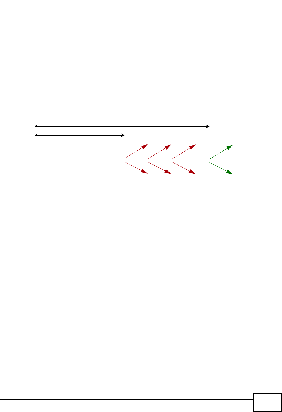
Appendix E IPv6
P-660HN-Tx User’s Guide 299
Each IA must be associated with exactly one interface. The DHCP client uses the
IA assigned to an interface to obtain configuration from a DHCP server for that
interface. Each IA consists of a unique IAID and associated IP information.
The IA type is the type of address in the IA. Each IA holds one type of address.
IA_NA means an identity association for non-temporary addresses and IA_TA is an
identity association for temporary addresses. An IA_NA option contains the T1 and
T2 fields, but an IA_TA option does not. The DHCPv6 server uses T1 and T2 to
control the time at which the client contacts with the server to extend the lifetimes
on any addresses in the IA_NA before the lifetimes expire. After T1, the client
sends the server (S1) (from which the addresses in the IA_NA were obtained) a
Renew message. If the time T2 is reached and the server does not respond, the
client sends a Rebind message to any available server (S2). For an IA_TA, the
client may send a Renew or Rebind message at the client's discretion.
DHCP Relay Agent
A DHCP relay agent is on the same network as the DHCP clients and helps forward
messages between the DHCP server and clients. When a client cannot use its link-
local address and a well-known multicast address to locate a DHCP server on its
network, it then needs a DHCP relay agent to send a message to a DHCP server
that is not attached to the same network.
The DHCP relay agent can add the remote identification (remote-ID) option and
the interface-ID option to the Relay-Forward DHCPv6 messages. The remote-ID
option carries a user-defined string, such as the system name. The interface-ID
option provides slot number, port information and the VLAN ID to the DHCPv6
server. The remote-ID option (if any) is stripped from the Relay-Reply messages
before the relay agent sends the packets to the clients. The DHCP server copies
the interface-ID option from the Relay-Forward message into the Relay-Reply
message and sends it to the relay agent. The interface-ID should not change even
after the relay agent restarts.
Prefix Delegation
Prefix delegation enables an IPv6 router to use the IPv6 prefix (network address)
received from the ISP (or a connected uplink router) for its LAN. The ZyXEL Device
uses the received IPv6 prefix (for example, 2001:db2::/48) to generate its LAN IP
address. Through sending Router Advertisements (RAs) regularly by multicast, the
T1
T2
Renew Rebind
Rebind
to S1
Renew
to S1
Renew
to S1
Renew
to S1
Renew
to S1
Renew
to S1
to S2
to S2

Appendix E IPv6
P-660HN-Tx User’s Guide
300
ZyXEL Device passes the IPv6 prefix information to its LAN hosts. The hosts then
can use the prefix to generate their IPv6 addresses.
ICMPv6
Internet Control Message Protocol for IPv6 (ICMPv6 or ICMP for IPv6) is defined in
RFC 4443. ICMPv6 has a preceding Next Header value of 58, which is different
from the value used to identify ICMP for IPv4. ICMPv6 is an integral part of IPv6.
IPv6 nodes use ICMPv6 to report errors encountered in packet processing and
perform other diagnostic functions, such as "ping".
Multicast Listener Discovery
The Multicast Listener Discovery (MLD) protocol (defined in RFC 2710) is derived
from IPv4's Internet Group Management Protocol version 2 (IGMPv2). MLD uses
ICMPv6 message types, rather than IGMP message types. MLDv1 is equivalent to
IGMPv2 and MLDv2 is equivalent to IGMPv3.
MLD allows an IPv6 switch or router to discover the presence of MLD listeners who
wish to receive multicast packets and the IP addresses of multicast groups the
hosts want to join on its network.
MLD snooping and MLD proxy are analogous to IGMP snooping and IGMP proxy in
IPv4.
MLD filtering controls which multicast groups a port can join.
MLD Messages
A multicast router or switch periodically sends general queries to MLD hosts to
update the multicast forwarding table. When an MLD host wants to join a
multicast group, it sends an MLD Report message for that address.
An MLD Done message is equivalent to an IGMP Leave message. When an MLD
host wants to leave a multicast group, it can send a Done message to the router
or switch. The router or switch then sends a group-specific query to the port on
which the Done message is received to determine if other devices connected to
this port should remain in the group.
Example - Enabling IPv6 on Windows XP/2003/Vista
By default, Windows XP and Windows 2003 support IPv6. This example shows you
how to use the ipv6 install command on Windows XP/2003 to enable IPv6. This

Appendix E IPv6
P-660HN-Tx User’s Guide 301
also displays how to use the ipconfig command to see auto-generated IP
addresses.
IPv6 is installed and enabled by default in Windows Vista. Use the ipconfig
command to check your automatic configured IPv6 address as well. You should
see at least one IPv6 address available for the interface on your computer.
Example - Enabling DHCPv6 on Windows XP
Windows XP does not support DHCPv6. If your network uses DHCPv6 for IP
address assignment, you have to additionally install a DHCPv6 client software on
your Windows XP. (Note: If you use static IP addresses or Router Advertisement
for IPv6 address assignment in your network, ignore this section.)
This example uses Dibbler as the DHCPv6 client. To enable DHCPv6 client on your
computer:
1Install Dibbler and select the DHCPv6 client option on your computer.
2After the installation is complete, select Start > All Programs > Dibbler-
DHCPv6 > Client Install as service.
3Select Start > Control Panel > Administrative Tools > Services.
C:\>ipv6 install
Installing...
Succeeded.
C:\>ipconfig
Windows IP Configuration
Ethernet adapter Local Area Connection:
Connection-specific DNS Suffix . :
IP Address. . . . . . . . . . . . : 10.1.1.46
Subnet Mask . . . . . . . . . . . : 255.255.255.0
IP Address. . . . . . . . . . . . : fe80::2d0:59ff:feb8:103c%4
Default Gateway . . . . . . . . . : 10.1.1.254
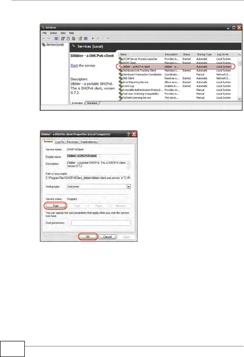
Appendix E IPv6
P-660HN-Tx User’s Guide
302
4Double click Dibbler - a DHCPv6 client.
5Click Start and then OK.
6Now your computer can obtain an IPv6 address from a DHCPv6 server.
Example - Enabling IPv6 on Windows 7
Windows 7 supports IPv6 by default. DHCPv6 is also enabled when you enable
IPv6 on a Windows 7 computer.
To enable IPv6 in Windows 7:
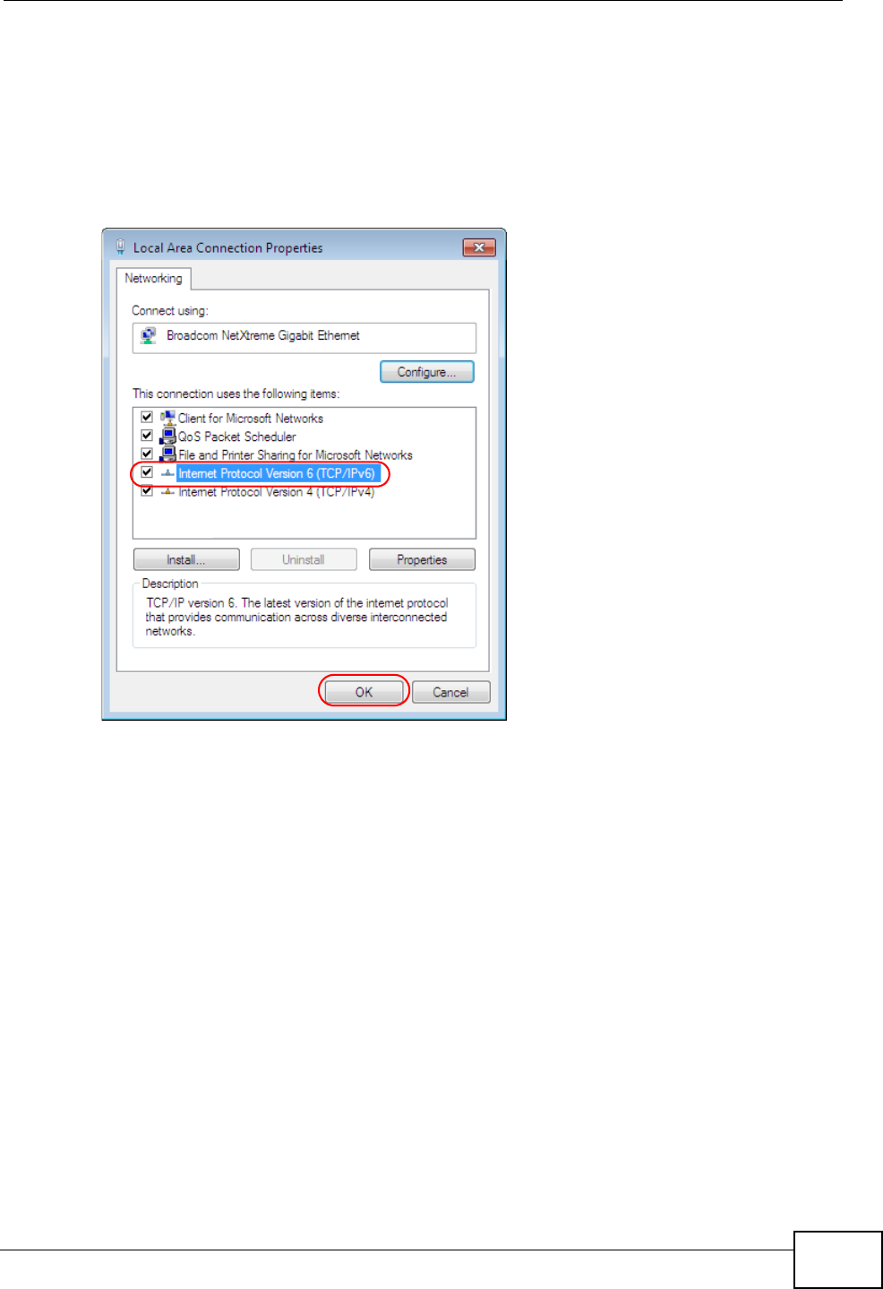
Appendix E IPv6
P-660HN-Tx User’s Guide 303
1Select Control Panel > Network and Sharing Center > Local Area
Connection.
2Select the Internet Protocol Version 6 (TCP/IPv6) checkbox to enable it.
3Click OK to save the change.
4Click Close to exit the Local Area Connection Status screen.
5Select Start > All Programs > Accessories > Command Prompt.

Appendix E IPv6
P-660HN-Tx User’s Guide
304
6Use the ipconfig command to check your dynamic IPv6 address. This example
shows a global address (2001:b021:2d::1000) obtained from a DHCP server.
C:\>ipconfig
Windows IP Configuration
Ethernet adapter Local Area Connection:
Connection-specific DNS Suffix . :
IPv6 Address. . . . . . . . . . . : 2001:b021:2d::1000
Link-local IPv6 Address . . . . . : fe80::25d8:dcab:c80a:5189%11
IPv4 Address. . . . . . . . . . . : 172.16.100.61
Subnet Mask . . . . . . . . . . . : 255.255.255.0
Default Gateway . . . . . . . . . : fe80::213:49ff:feaa:7125%11
172.16.100.254

P-660HN-Tx User’s Guide 305
APPENDIX F
Services
The following table lists some commonly-used services and their associated
protocols and port numbers.
•Name: This is a short, descriptive name for the service. You can use this one or
create a different one, if you like.
•Protocol: This is the type of IP protocol used by the service. If this is TCP/
UDP, then the service uses the same port number with TCP and UDP. If this is
USER-DEFINED, the Port(s) is the IP protocol number, not the port number.
•Port(s): This value depends on the Protocol.
•If the Protocol is TCP, UDP, or TCP/UDP, this is the IP port number.
•If the Protocol is USER, this is the IP protocol number.
•Description: This is a brief explanation of the applications that use this service
or the situations in which this service is used.

Appendix F Services
P-660HN-Tx User’s Guide
306
Table 99 Examples of Services
NAME PROTOCOL PORT(S) DESCRIPTION
AH
(IPSEC_TUNNEL)
User-Defined 51 The IPSEC AH (Authentication Header)
tunneling protocol uses this service.
AIM TCP 5190 AOL’s Internet Messenger service.
AUTH TCP 113 Authentication protocol used by some
servers.
BGP TCP 179 Border Gateway Protocol.
BOOTP_CLIENT UDP 68 DHCP Client.
BOOTP_SERVER UDP 67 DHCP Server.
CU-SEEME TCP/UDP
TCP/UDP
7648
24032
A popular videoconferencing solution
from White Pines Software.
DNS TCP/UDP 53 Domain Name Server, a service that
matches web names (for instance
www.zyxel.com) to IP numbers.
ESP
(IPSEC_TUNNEL)
User-Defined 50 The IPSEC ESP (Encapsulation
Security Protocol) tunneling protocol
uses this service.
FINGER TCP 79 Finger is a UNIX or Internet related
command that can be used to find out
if a user is logged on.
FTP TCP
TCP
20
21
File Transfer Protocol, a program to
enable fast transfer of files, including
large files that may not be possible by
e-mail.
H.323 TCP 1720 NetMeeting uses this protocol.
HTTP TCP 80 Hyper Text Transfer Protocol - a client/
server protocol for the world wide
web.
HTTPS TCP 443 HTTPS is a secured http session often
used in e-commerce.
ICMP User-Defined 1Internet Control Message Protocol is
often used for diagnostic purposes.
ICQ UDP 4000 This is a popular Internet chat
program.
IGMP
(MULTICAST)
User-Defined 2Internet Group Multicast Protocol is
used when sending packets to a
specific group of hosts.
IKE UDP 500 The Internet Key Exchange algorithm
is used for key distribution and
management.
IMAP4 TCP 143 The Internet Message Access Protocol
is used for e-mail.
IMAP4S TCP 993 This is a more secure version of IMAP4
that runs over SSL.
IRC TCP/UDP 6667 This is another popular Internet chat
program.

Appendix F Services
P-660HN-Tx User’s Guide 307
MSN Messenger TCP 1863 Microsoft Networks’ messenger
service uses this protocol.
NetBIOS TCP/UDP
TCP/UDP
TCP/UDP
TCP/UDP
137
138
139
445
The Network Basic Input/Output
System is used for communication
between computers in a LAN.
NEW-ICQ TCP 5190 An Internet chat program.
NEWS TCP 144 A protocol for news groups.
NFS UDP 2049 Network File System - NFS is a client/
server distributed file service that
provides transparent file sharing for
network environments.
NNTP TCP 119 Network News Transport Protocol is
the delivery mechanism for the
USENET newsgroup service.
PING User-Defined 1Packet INternet Groper is a protocol
that sends out ICMP echo requests to
test whether or not a remote host is
reachable.
POP3 TCP 110 Post Office Protocol version 3 lets a
client computer get e-mail from a
POP3 server through a temporary
connection (TCP/IP or other).
POP3S TCP 995 This is a more secure version of POP3
that runs over SSL.
PPTP TCP 1723 Point-to-Point Tunneling Protocol
enables secure transfer of data over
public networks. This is the control
channel.
PPTP_TUNNEL
(GRE)
User-Defined 47 PPTP (Point-to-Point Tunneling
Protocol) enables secure transfer of
data over public networks. This is the
data channel.
RCMD TCP 512 Remote Command Service.
REAL_AUDIO TCP 7070 A streaming audio service that
enables real time sound over the web.
REXEC TCP 514 Remote Execution Daemon.
RLOGIN TCP 513 Remote Login.
ROADRUNNER TCP/UDP 1026 This is an ISP that provides services
mainly for cable modems.
RTELNET TCP 107 Remote Telnet.
RTSP TCP/UDP 554 The Real Time Streaming (media
control) Protocol (RTSP) is a remote
control for multimedia on the
Internet.
Table 99 Examples of Services (continued)
NAME PROTOCOL PORT(S) DESCRIPTION

Appendix F Services
P-660HN-Tx User’s Guide
308
SFTP TCP 115 The Simple File Transfer Protocol is an
old way of transferring files between
computers.
SMTP TCP 25 Simple Mail Transfer Protocol is the
message-exchange standard for the
Internet. SMTP enables you to move
messages from one e-mail server to
another.
SMTPS TCP 465 This is a more secure version of SMTP
that runs over SSL.
SNMP TCP/UDP 161 Simple Network Management
Program.
SNMP-TRAPS TCP/UDP 162 Traps for use with the SNMP
(RFC:1215).
SQL-NET TCP 1521 Structured Query Language is an
interface to access data on many
different types of database systems,
including mainframes, midrange
systems, UNIX systems and network
servers.
SSDP UDP 1900 The Simple Service Discovery Protocol
supports Universal Plug-and-Play
(UPnP).
SSH TCP/UDP 22 Secure Shell Remote Login Program.
STRM WORKS UDP 1558 Stream Works Protocol.
SYSLOG UDP 514 Syslog allows you to send system logs
to a UNIX server.
TACACS UDP 49 Login Host Protocol used for (Terminal
Access Controller Access Control
System).
TELNET TCP 23 Telnet is the login and terminal
emulation protocol common on the
Internet and in UNIX environments. It
operates over TCP/IP networks. Its
primary function is to allow users to
log into remote host systems.
VDOLIVE TCP
UDP
7000
user-
defined
A videoconferencing solution. The UDP
port number is specified in the
application.
Table 99 Examples of Services (continued)
NAME PROTOCOL PORT(S) DESCRIPTION

P-660HN-Tx User’s Guide 309
APPENDIX G
Legal Information
Copyright
Copyright © 2011 by ZyXEL Communications Corporation.
The contents of this publication may not be reproduced in any part or as a whole,
transcribed, stored in a retrieval system, translated into any language, or
transmitted in any form or by any means, electronic, mechanical, magnetic,
optical, chemical, photocopying, manual, or otherwise, without the prior written
permission of ZyXEL Communications Corporation.
Published by ZyXEL Communications Corporation. All rights reserved.
Disclaimer
ZyXEL does not assume any liability arising out of the application or use of any
products, or software described herein. Neither does it convey any license under
its patent rights nor the patent rights of others. ZyXEL further reserves the right
to make changes in any products described herein without notice. This publication
is subject to change without notice.
Trademarks
ZyNOS (ZyXEL Network Operating System) is a registered trademark of ZyXEL
Communications, Inc. Other trademarks mentioned in this publication are used for
identification purposes only and may be properties of their respective owners.
Certifications
Federal Communications Commission (FCC) Interference Statement
The device complies with Part 15 of FCC rules. Operation is subject to the
following two conditions:
• This device may not cause harmful interference.
Appendix G Legal Information
P-660HN-Tx User’s Guide
310
•This device must accept any interference received, including interference that
may cause undesired operations.
This device has been tested and found to comply with the limits for a Class B
digital device pursuant to Part 15 of the FCC Rules. These limits are designed to
provide reasonable protection against harmful interference in a residential
installation. This device generates, uses, and can radiate radio frequency energy,
and if not installed and used in accordance with the instructions, may cause
harmful interference to radio communications. However, there is no guarantee
that interference will not occur in a particular installation.
If this device does cause harmful interference to radio/television reception, which
can be determined by turning the device off and on, the user is encouraged to try
to correct the interference by one or more of the following measures:
1Reorient or relocate the receiving antenna.
2Increase the separation between the equipment and the receiver.
3Connect the equipment into an outlet on a circuit different from that to which the
receiver is connected.
4Consult the dealer or an experienced radio/TV technician for help.
FCC Radiation Exposure Statement
• This transmitter must not be co-located or operating in conjunction with any
other antenna or transmitter.
• IEEE 802.11b, 802.11g or 802.11n(20MHz) operation of this product in the
U.S.A. is firmware-limited to channels 1 through 11. IEEE 802.11n(40MHz)
operation of this product in the U.S.A. is firmware-limited to channels 3 through
9.
• To comply with FCC RF exposure compliance requirements, a separation
distance of at least 20 cm must be maintained between the antenna of this
device and all persons.

Appendix G Legal Information
P-660HN-Tx User’s Guide 311
Notices
Changes or modifications not expressly approved by the party responsible for
compliance could void the user's authority to operate the equipment.
This device has been designed for the WLAN 2.4 GHz network throughout the EC
region and Switzerland, with restrictions in France.
This Class B digital apparatus complies with Canadian ICES-003.
Cet appareil numérique de la classe B est conforme à la norme NMB-003 du
Canada.
Viewing Certifications
1Go to http://www.zyxel.com.
2Select your product on the ZyXEL home page to go to that product's page.
3Select the certification you wish to view from this page.
ZyXEL Limited Warranty
ZyXEL warrants to the original end user (purchaser) that this product is free from
any defects in materials or workmanship for a period of up to two years from the
date of purchase. During the warranty period, and upon proof of purchase, should
the product have indications of failure due to faulty workmanship and/or
materials, ZyXEL will, at its discretion, repair or replace the defective products or
components without charge for either parts or labor, and to whatever extent it
shall deem necessary to restore the product or components to proper operating
condition. Any replacement will consist of a new or re-manufactured functionally
equivalent product of equal or higher value, and will be solely at the discretion of
ZyXEL. This warranty shall not apply if the product has been modified, misused,
tampered with, damaged by an act of God, or subjected to abnormal working
conditions.
Note
Repair or replacement, as provided under this warranty, is the exclusive remedy of
the purchaser. This warranty is in lieu of all other warranties, express or implied,

Appendix G Legal Information
P-660HN-Tx User’s Guide
312
including any implied warranty of merchantability or fitness for a particular use or
purpose. ZyXEL shall in no event be held liable for indirect or consequential
damages of any kind to the purchaser.
To obtain the services of this warranty, contact ZyXEL's Service Center for your
Return Material Authorization number (RMA). Products must be returned Postage
Prepaid. It is recommended that the unit be insured when shipped. Any returned
products without proof of purchase or those with an out-dated warranty will be
repaired or replaced (at the discretion of ZyXEL) and the customer will be billed
for parts and labor. All repaired or replaced products will be shipped by ZyXEL to
the corresponding return address, Postage Paid. This warranty gives you specific
legal rights, and you may also have other rights that vary from country to country.
Registration
Register your product online to receive e-mail notices of firmware upgrades and
information at www.zyxel.com for global products, or at www.us.zyxel.com for
North American products.

Index
P-660HN-Tx User’s Guide 313
Index
Numerics
802.1p 171, 173
A
activation
CWMP 198
dynamic DNS 176
DYNDNS wildcard 176
firewalls 145
MAC address filter 111
NAT 133
port forwarding 136
QoS 167, 170
SIP ALG 137
SPI 145
SSID 111
UPnP 187
wireless LAN 105
WPS 114
address mapping
types 140
administrator password 30, 202
alerts 205
alternative subnet mask notation 262
antenna
directional 294
gain 293
omni-directional 294
AP (access point) 281
applications, NAT 140
Asynchronous Transfer Mode, see ATM
ATM 219
MBS 77, 83
PCR 77, 82
QoS 77, 82, 87
SCR 77, 83
status 219
authentication 117, 119
RADIUS server 119
B
backup
configuration 212
Basic Service Set, See BSS 279
Basic Service Set, see BSS
broadcast 72
BSS 121, 279
example 122
C
CA 155, 287
CBR 77, 82, 87
Certificate Authority
See CA.
certificates 155
authentication 155
CA
public key 155
Certification Authority 155
Certification Authority. see CA
certifications 309
notices 311
viewing 311
channel 281
interference 281
channel, wireless LAN 117
CLI 22
client list 94
Command Line Interface, see CLI
configuration
backup 212
CWMP 198
DHCP 94
firewalls 145

Index
P-660HN-Tx User’s Guide
314
IP alias 96
IP precedence 171
IP/MAC filter 150, 152
logs 205
port forwarding 134
reset 214
restoring 213
static route 161, 163
WAN 73
wireless LAN 105
wizard 60
connection
nailed-up 81, 86
on demand 81
copyright 309
CPE WAN Management Protocol, see CWMP
CTS (Clear to Send) 282
CTS threshold 109, 117
CWMP 197
activation 198
configuration 198
D
data fragment threshold 109, 117
DDoS 144
default server, NAT 133, 135
Denials of Service, see DoS
DHCP 90, 94, 99
diagnostic 217
DiffServ Code Point, see DSCP
digital IDs 155
disclaimer 309
DNS 90, 94, 99
Domain Name System, see DNS
DoS 143
DSCP 171
DSL connections, status 220
dynamic DNS 175
activation 176
wildcard 175
activation 176
Dynamic Host Configuration Protocol, see DHCP
dynamic WEP key exchange 288
DYNDNS wildcard 175
activation 176
E
EAP Authentication 286
encapsulation 71, 74, 80
ENET ENCAP 83
PPPoA 84
PPPoE 84
RFC 1483 84
encryption 106, 120, 289
WEP 107
key 108
WPA-PSK 108
pre-shared key 109
ENET ENCAP 74, 80, 83
ESS 280
Extended Service Set, See ESS 280
F
FCC interference statement 309
filters 147
IP/MAC 149
structure 147
IP/MAC filter
configuration 150, 152
MAC address 110, 119
activation 111
URL 147, 148
firewalls 143
configuration 145
DDoS 144
DoS 143
LAND attack 144
Ping of Death 144
status 39
SYN attack 143
firmware 209
version 38
forwarding ports 132, 133
activation 136
configuration 134
example 134

Index
P-660HN-Tx User’s Guide 315
rules 136
fragmentation threshold 109, 117, 283
FTP 22, 180
H
hidden node 281
I
IANA 267
Internet Assigned Numbers Authority
see IANA
IBSS 279
ICMP 184
IEEE 802.11g 283
IGA 138
IGMP 72, 90, 92, 101
ILA 138
Independent Basic Service Set
See IBSS 279
initialization vector (IV) 289
Inside Global Address, see IGA
Inside Local Address, see ILA
Internet Group Multicast Protocol, see IGMP
Internet Protocol version 6, see IPv6
IP address 72, 74, 80, 85, 90, 100
default server 133, 135
ping 217
private 100
IP alias 96
configuration 96
NAT applications 140
IP precedence 172, 173
configuration 171
IP/MAC filter 149
configuration 150, 152
structure 147
IPv6 295
addressing 295
EUI-64 297
global address 296
interface ID 297
link-local address 296
Neighbor Discovery Protocol 295
ping 295
prefix 295
prefix length 295
stateless autoconfiguration 298
unspecified address 296
L
LAN 89
client list 94
DHCP 90, 94, 99
DNS 90, 94, 99
IGMP 90, 101
IP address 90, 91, 100
IP alias 96
configuration 96
MAC address 95
multicast 90, 92, 101
RIP 90, 101
status 38
subnet mask 90, 91, 100
LAND attack 144
LEDs 26
limitations
wireless LAN 121
WPS 128
Local Area Network, see LAN
login 29
passwords 30
logs 205
alerts 205
settings 205
M
MAC address 95, 111
filter 104, 106, 110, 119
MAC address filter
activation 111
Management Information Base (MIB) 182
mapping address
types 140

Index
P-660HN-Tx User’s Guide
316
Maximum Burst Size, see MBS
MBS 77, 83, 86
MBSSID 122
MTU 83
multicast 72, 76, 90, 92, 101
IGMPInternet Group Multicast Protocol, see
IGMP
Multiple BSS, see MBSSID
multiplexing 74, 80, 84
LLC-based 85
VC-based 85
N
nailed-up connection 75, 81, 86
NAT 81, 131, 132, 137, 138, 267
activation 133
address mapping
types 140
applications 140
IP alias 140
default server IP address 133, 135
example 139
global 138
IGA 138
ILA 138
inside 138
local 138
outside 138
port forwarding 132, 133
activation 136
configuration 134
example 134
rules 136
remote management 178
SIP ALG 137
activation 137
Network Address Translation
see NAT
Network Address Translation, see NAT
P
Pairwise Master Key (PMK) 289, 291
passwords 30
administrator 202
PBC 123
PCR 77, 82, 86
Peak Cell Rate, see PCR
PIN, WPS 115, 124
example 125
Ping of Death 144
port forwarding 132, 133
activation 136
configuration 134
example 134
rules 136
PPPoA 74, 80, 84
PPPoE 74, 80, 84
preamble 110, 117
preamble mode 283
pre-shared key 109
private IP address 100
product registration 312
PSK 289
push button 24, 115
Push Button Configuration, see PBC
push button, WPS 123
Q
QoS 165
802.1p 171, 173
activation 167, 170
DSCP 171
example 165
IP precedence 172, 173
priority queue 173
Quality of Service, see QoS
R
RADIUS 285
message types 285
messages 285
shared secret key 286
RADIUS server 119
registration

Index
P-660HN-Tx User’s Guide 317
product 312
related documentation 3
remote management 177
FTP 180
ICMP 184
limitations 178
NAT 178
Telnet 180
WWW 179
reset 27, 214
restart 215
restoring configuration 213
RFC 1483 74, 80, 84
RIP 76, 90, 101
Routing Information Protocol, see RIP
RTS (Request To Send) 282
threshold 281, 282
RTS threshold 109, 117
rules, port forwarding 136
S
safety warnings 7
SCR 77, 83, 86
security
wireless LAN 106, 118
Security Parameter Index, see SPI
Service Set IDentifier, see SSID
setup
DHCP 94
firewalls 145
IP alias 96
IP precedenceQoS
IP precedence 171
IP/MAC filter 150, 152
logs 205
port forwarding 134
static route 161, 163
WAN 73
wireless LAN 105
wizard 60
shaping traffic 86, 87
Simple Network Management Protocol, see
SNMP
SIP ALG 137
activation 137
SNMP 181
agents 182
Manager 182
managers 182
MIB 182
network components 182
versions 181
SPI 144
activation 145
SSID 104, 106, 113, 118
activation 111
MBSSID 122
static route 159
configuration 161, 163
example 159
status 33, 37, 40
ATM 219
DSL connections 220
firewalls 39
firmware version 38
LAN 38
WAN 38
wireless LAN 39
WPS 114
subnet 259
subnet mask 90, 100, 260
subnetting 262
Sustain Cell Rate, see SCR
SYN attack 143
syntax conventions 5
system 201
firmware 209
version 38
LED 26
passwords 30
administrator 202
reset 27
status 33, 37
firewalls 39
LAN 38
WAN 38
wireless LAN 39
time 202

Index
P-660HN-Tx User’s Guide
318
T
Telnet 180
thresholds
data fragment 109, 117
RTS/CTS 109, 117
time 202
TR-069 22
trademarks 309
traffic shaping 86
example 87
U
UBR 77, 82, 88
unicast 72
Universal Plug and Play, see UPnP
upgrading firmware 209
UPnP 185
activation 187
cautions 186
example 188
installation 188
NAT traversal 185
URL 147
URL filter 148
URL 147
V
VBR 87
VBR-nRT 77, 82, 88
VBR-RT 77, 82, 87
VCI 74, 80, 85
Virtual Channel Identifier, see VCI
Virtual Path Identifier, see VPI
VPI 74, 80, 85
W
WAN 71
ATM QoS 77, 82, 87
encapsulation 71, 74, 80
IGMP 72
IP address 72, 74, 80, 85
mode 73, 79
MTU 83
multicast 72, 76
multiplexing 74, 80, 84
nailed-up connection 75, 81, 86
NAT 81
RIP 76
setup 73
status 38
traffic shaping 86
example 87
VCI 74, 80, 85
VPI 74, 80, 85
warranty 311
note 311
web configurator 22, 29
login 29
passwords 30
WEP 107, 120
key 108
Wide Area Network, see WAN
Wi-Fi Protected Access 288
WiFi Protected Setup, see WPS
wireless client WPA supplicants 290
wireless LAN 103, 115
activation 105
authentication 117, 119
BSS 121
example 122
channel 117
configuration 105
encryption 106, 120
example 116
fragmentation threshold 109, 117
limitations 121
MAC address filter 104, 106, 110, 111, 119
MBSSID 122
preamble 110, 117
RADIUS server 119
RTS/CTS threshold 109, 117
security 118
SSID 104, 106, 113, 118
activation 111
status 39

Index
P-660HN-Tx User’s Guide 319
WEP 107, 120
key 108
wizard 66
WPA 120
WPA-PSK 108, 120
pre-shared key 109
WPS 113, 123, 125
activation 114
adding stations 115
example 127
limitations 128
PIN 115, 124
push button 24, 115, 123
status 114
wireless security 284
Wireless tutorial 43
wizard 57
configuration 60
wireless LAN 66
WLAN
interference 281
security parameters 292
WPA 120, 288
key caching 290
pre-authentication 290
user authentication 290
vs WPA-PSK 289
wireless client supplicant 290
with RADIUS application example 290
WPA2 288
user authentication 290
vs WPA2-PSK 289
wireless client supplicant 290
with RADIUS application example 290
WPA2-Pre-Shared Key 288
WPA2-PSK 288, 289
application example 291
WPA-PSK 108, 120, 289
application example 291
pre-shared key 109
WPS 113, 123, 125
activation 114
adding stations 115
example 127
limitations 128
PIN 115, 124
example 125
push button 24, 115, 123
status 114

Index
P-660HN-Tx User’s Guide
320

Index
P-660HN-Tx User’s Guide 321

Index
P-660HN-Tx User’s Guide
322