ZyXEL Communications P660HWDXV2 802.11g Wireless ADSL Gateway User Manual SMG 700 User s Guide V1 00 Nov 2004
ZyXEL Communications Corporation 802.11g Wireless ADSL Gateway SMG 700 User s Guide V1 00 Nov 2004
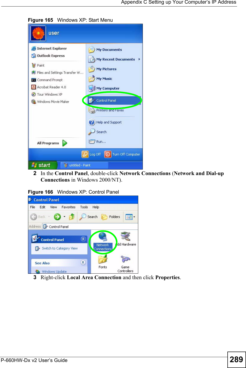
UserManual.wiki
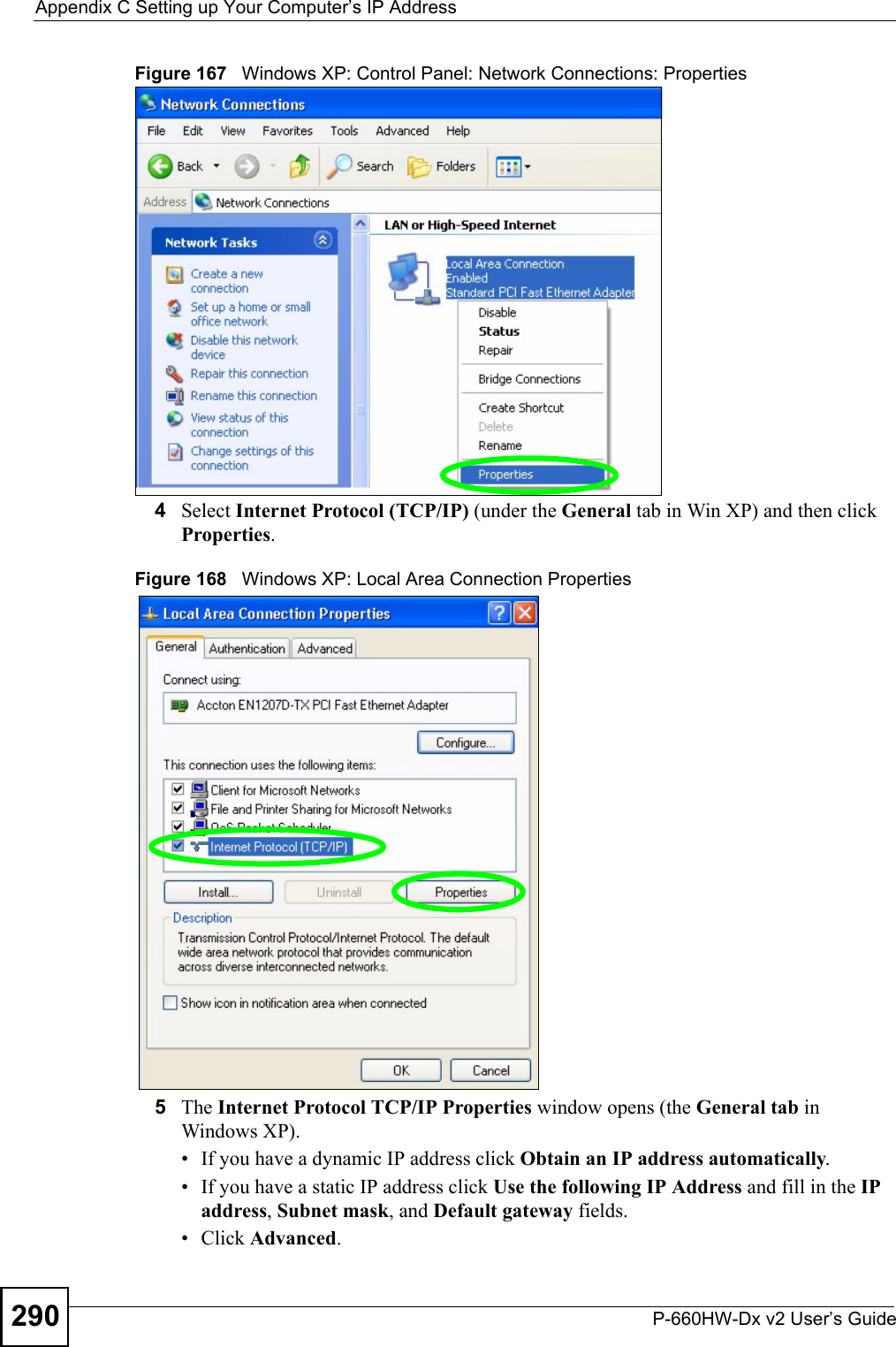
>
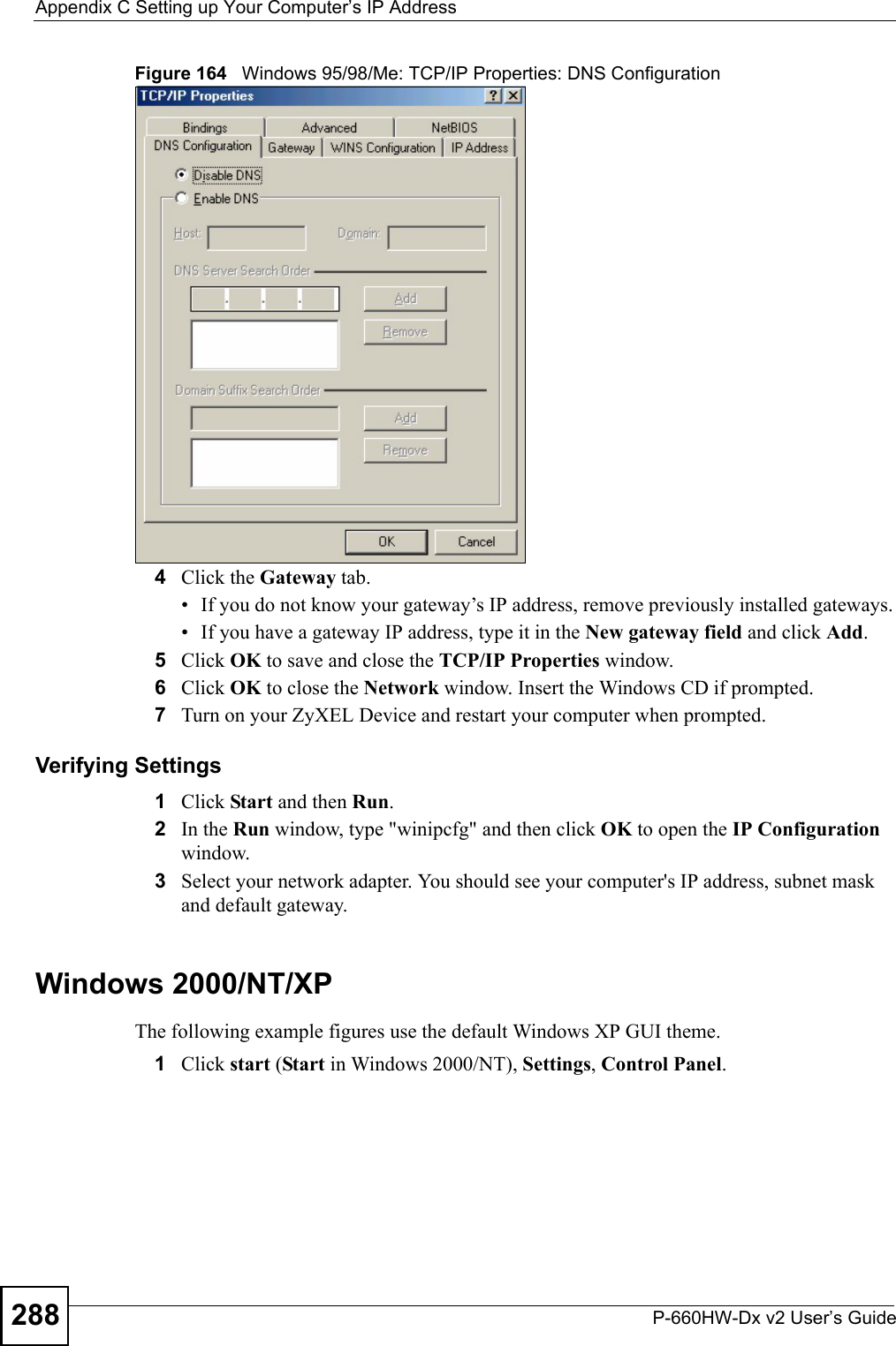
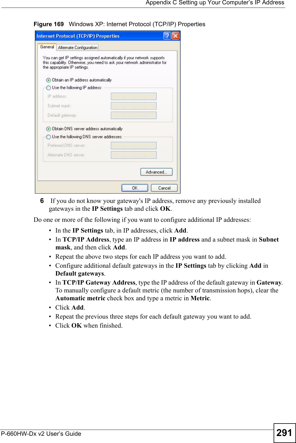
ZyXEL Communications
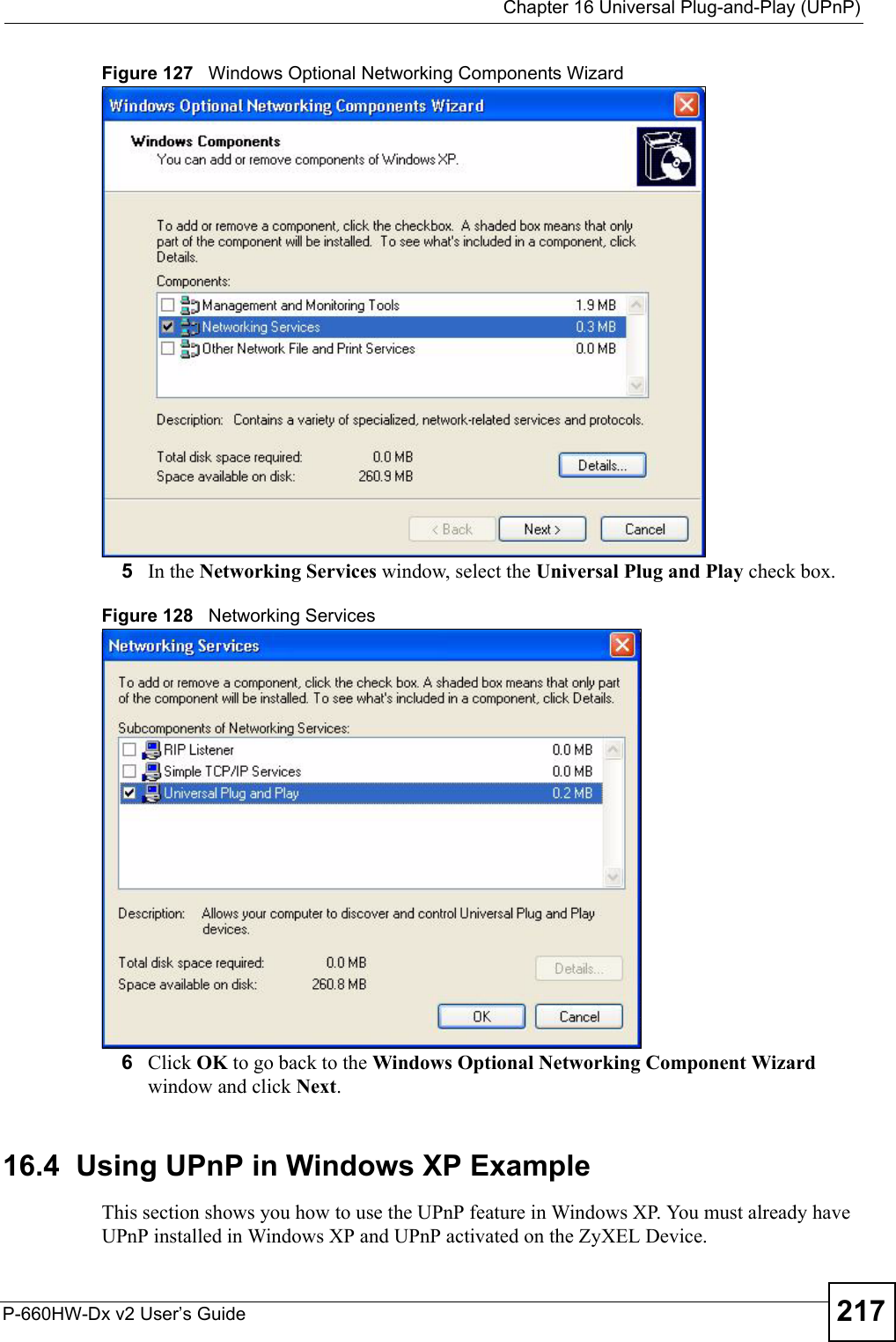
>
P660HWDXV2 User Manual
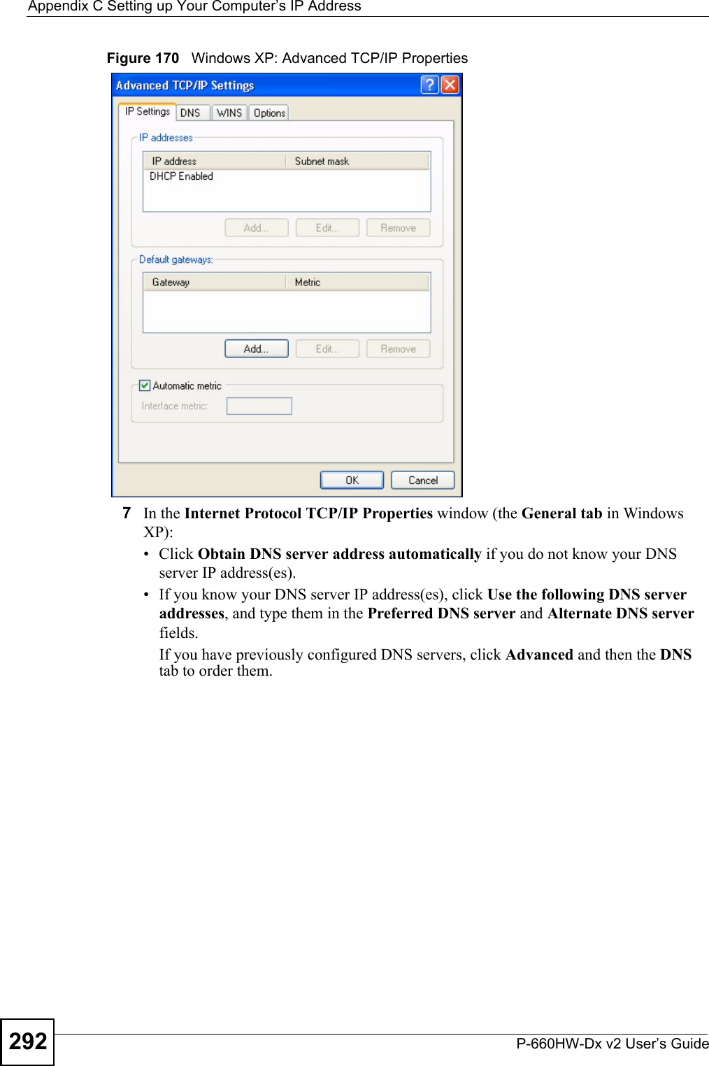
>
Part3
Contents
1.
Part1
2.
Part2
3.
Part3
4.
Part4
Part3
Navigation menu
Upload a User Manual
Namespaces
Wiki Guide
HTML
PDF
Info
Views
User Manual
Discussion / Help
Navigation

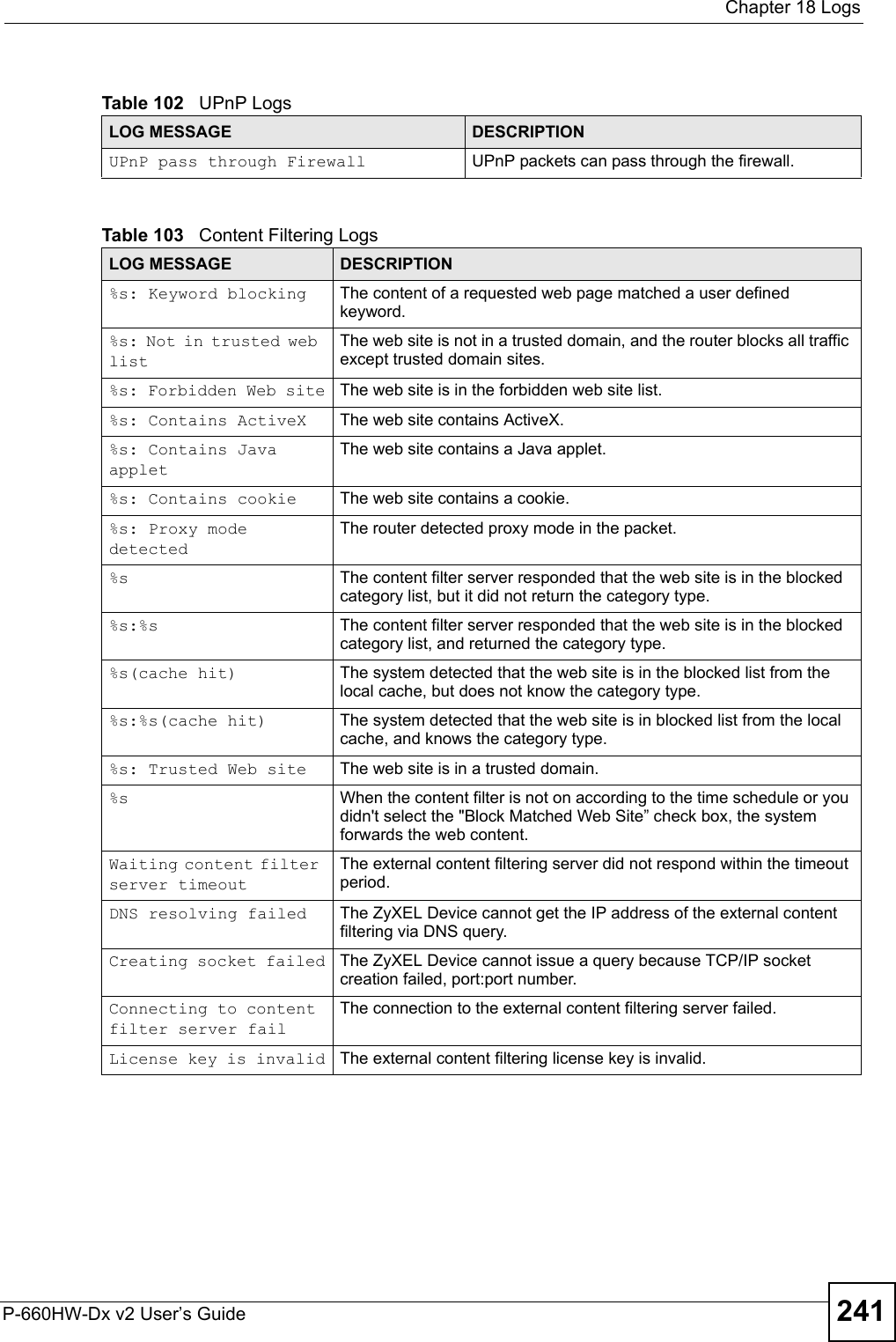
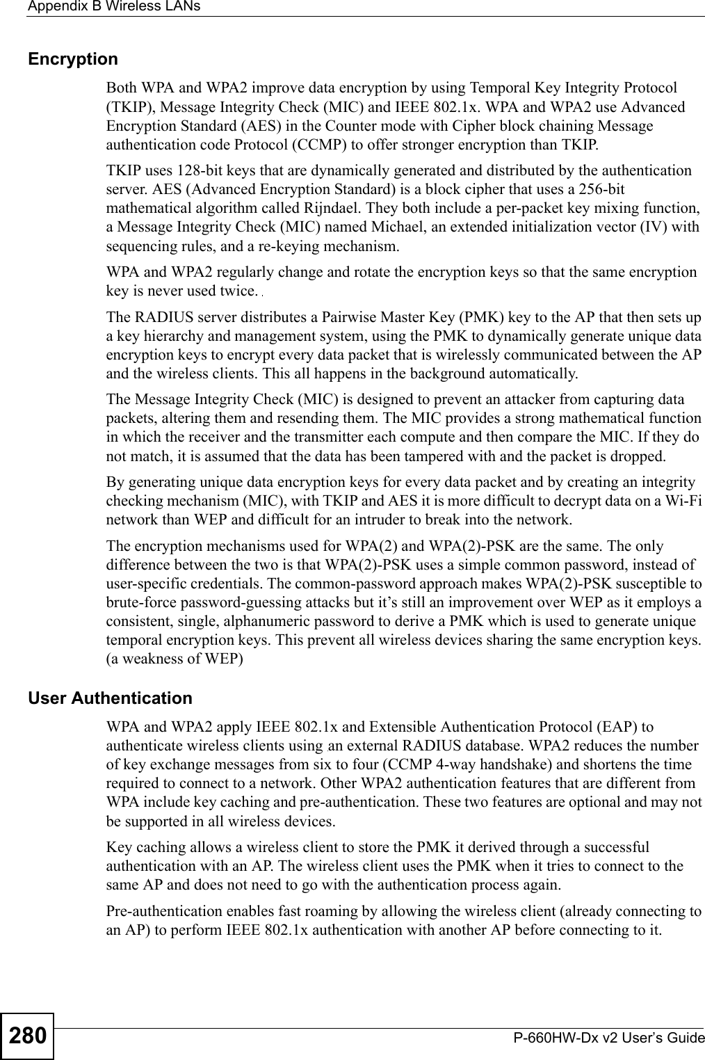
![Chapter 18 LogsP-660HW-Dx v2 User’s Guide238 Starting Connectivity MonitorStarting Connectivity Monitor.Time initialized by Daytime ServerThe router got the time and date from the Daytime server.Time initialized by Time serverThe router got the time and date from the time server.Time initialized by NTP serverThe router got the time and date from the NTP server.Connect to Daytime server failThe router was not able to connect to the Daytime server.Connect to Time server fail The router was not able to connect to the Time server.Connect to NTP server fail The router was not able to connect to the NTP server.Too large ICMP packet has been droppedThe router dropped an ICMP packet that was too large.Configuration Change: PC = 0x%x, Task ID = 0x%xThe router is saving configuration changes.Successful SSH login Someone has logged on to the router’s SSH server.SSH login failed Someone has failed to log on to the router’s SSH server.Successful HTTPS login Someone has logged on to the router's web configurator interface using HTTPS protocol.HTTPS login failed Someone has failed to log on to the router's web configurator interface using HTTPS protocol.Table 95 System Error LogsLOG MESSAGE DESCRIPTION%s exceeds the max. number of session per host!This attempt to create a NAT session exceeds the maximum number of NAT session table entries allowed to be created per host.setNetBIOSFilter: calloc errorThe router failed to allocate memory for the NetBIOS filter settings.readNetBIOSFilter: calloc errorThe router failed to allocate memory for the NetBIOS filter settings.WAN connection is down. A WAN connection is down. You cannot access the network through this interface.Table 96 Access Control LogsLOG MESSAGE DESCRIPTIONFirewall default policy: [TCP | UDP | IGMP | ESP | GRE | OSPF] <Packet Direction>Attempted TCP/UDP/IGMP/ESP/GRE/OSPF access matched the default policy and was blocked or forwarded according to the default policy’s setting.Firewall rule [NOT] match:[TCP | UDP | IGMP | ESP | GRE | OSPF] <Packet Direction>, <rule:%d>Attempted TCP/UDP/IGMP/ESP/GRE/OSPF access matched (or did not match) a configured firewall rule (denoted by its number) and was blocked or forwarded according to the rule. Table 94 System Maintenance Logs (continued)LOG MESSAGE DESCRIPTION](https://usermanual.wiki/ZyXEL-Communications/P660HWDXV2.Part3/User-Guide-803152-Page-38.png)
![Chapter 18 LogsP-660HW-Dx v2 User’s Guide 239 Triangle route packet forwarded: [TCP | UDP | IGMP | ESP | GRE | OSPF]The firewall allowed a triangle route session to pass through.Packet without a NAT table entry blocked: [TCP | UDP | IGMP | ESP | GRE | OSPF]The router blocked a packet that didn't have a corresponding NAT table entry.Router sent blocked web site message: TCPThe router sent a message to notify a user that the router blocked access to a web site that the user requested.Table 97 TCP Reset LogsLOG MESSAGE DESCRIPTIONUnder SYN flood attack, sent TCP RSTThe router sent a TCP reset packet when a host was under a SYN flood attack (the TCP incomplete count is per destination host.) Exceed TCP MAX incomplete, sent TCP RSTThe router sent a TCP reset packet when the number of TCP incomplete connections exceeded the user configured threshold. (the TCP incomplete count is per destination host.) Note: Refer to TCP Maximum Incomplete in the Firewall Attack Alerts screen. Peer TCP state out of order, sent TCP RSTThe router sent a TCP reset packet when a TCP connection state was out of order.Note: The firewall refers to RFC793 Figure 6 to check the TCP state.Firewall session time out, sent TCP RSTThe router sent a TCP reset packet when a dynamic firewall session timed out.The default timeout values are as follows:ICMP idle timeout: 3 minutesUDP idle timeout: 3 minutesTCP connection (three way handshaking) timeout: 270 secondsTCP FIN-wait timeout: 2 MSL (Maximum Segment Lifetime set in the TCP header).TCP idle (established) timeout (s): 150 minutesTCP reset timeout: 10 secondsExceed MAX incomplete, sent TCP RSTThe router sent a TCP reset packet when the number of incomplete connections (TCP and UDP) exceeded the user-configured threshold. (Incomplete count is for all TCP and UDP connections through the firewall.)Note: When the number of incomplete connections (TCP + UDP) > “Maximum Incomplete High”, the router sends TCP RST packets for TCP connections and destroys TOS (firewall dynamic sessions) until incomplete connections < “Maximum Incomplete Low”.Access block, sent TCP RSTThe router sends a TCP RST packet and generates this log if you turn on the firewall TCP reset mechanism (via CI command: "sys firewall tcprst").Table 98 Packet Filter LogsLOG MESSAGE DESCRIPTION[TCP | UDP | ICMP | IGMP | Generic] packet filter matched (set:%d, rule:%d)Attempted access matched a configured filter rule (denoted by its set and rule number) and was blocked or forwarded according to the rule.Table 96 Access Control Logs (continued)LOG MESSAGE DESCRIPTION](https://usermanual.wiki/ZyXEL-Communications/P660HWDXV2.Part3/User-Guide-803152-Page-39.png)
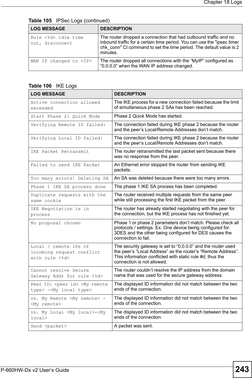
![Chapter 18 LogsP-660HW-Dx v2 User’s Guide240 Table 99 ICMP LogsLOG MESSAGE DESCRIPTIONFirewall default policy: ICMP <Packet Direction>, <type:%d>, <code:%d>ICMP access matched the default policy and was blocked or forwarded according to the user's setting. For type and code details, see Table 110 on page 248.Firewall rule [NOT] match: ICMP <Packet Direction>, <rule:%d>, <type:%d>, <code:%d>ICMP access matched (or didn’t match) a firewall rule (denoted by its number) and was blocked or forwarded according to the rule. For type and code details, see Table 110 on page 248.Triangle route packet forwarded: ICMPThe firewall allowed a triangle route session to pass through.Packet without a NAT table entry blocked: ICMPThe router blocked a packet that didn’t have a corresponding NAT table entry.Unsupported/out-of-order ICMP: ICMPThe firewall does not support this kind of ICMP packets or the ICMP packets are out of order.Router reply ICMP packet: ICMP The router sent an ICMP reply packet to the sender.Table 100 CDR LogsLOG MESSAGE DESCRIPTIONboard%d line%d channel%d, call%d,%s C01 Outgoing Call dev=%x ch=%x%sThe router received the setup requirements for a call. “call” is the reference (count) number of the call. “dev” is the device type (3 is for dial-up, 6 is for PPPoE, 10 is for PPTP). "channel" or “ch” is the call channel ID.For example,"board 0 line 0 channel 0, call 3, C01 Outgoing Call dev=6 ch=0 "Means the router has dialed to the PPPoE server 3 times.board%d line%d channel%d, call%d,%s C02 OutCall Connected%d%sThe PPPoE, PPTP or dial-up call is connected.board%d line%d channel%d, call%d,%s C02 Call TerminatedThe PPPoE, PPTP or dial-up call was disconnected.Table 101 PPP LogsLOG MESSAGE DESCRIPTIONppp:LCP Starting The PPP connection’s Link Control Protocol stage has started.ppp:LCP Opening The PPP connection’s Link Control Protocol stage is opening.ppp:CHAP Opening The PPP connection’s Challenge Handshake Authentication Protocol stage is opening.ppp:IPCP StartingThe PPP connection’s Internet Protocol Control Protocol stage is starting.ppp:IPCP Opening The PPP connection’s Internet Protocol Control Protocol stage is opening.ppp:LCP Closing The PPP connection’s Link Control Protocol stage is closing.ppp:IPCP Closing The PPP connection’s Internet Protocol Control Protocol stage is closing.](https://usermanual.wiki/ZyXEL-Communications/P660HWDXV2.Part3/User-Guide-803152-Page-40.png)
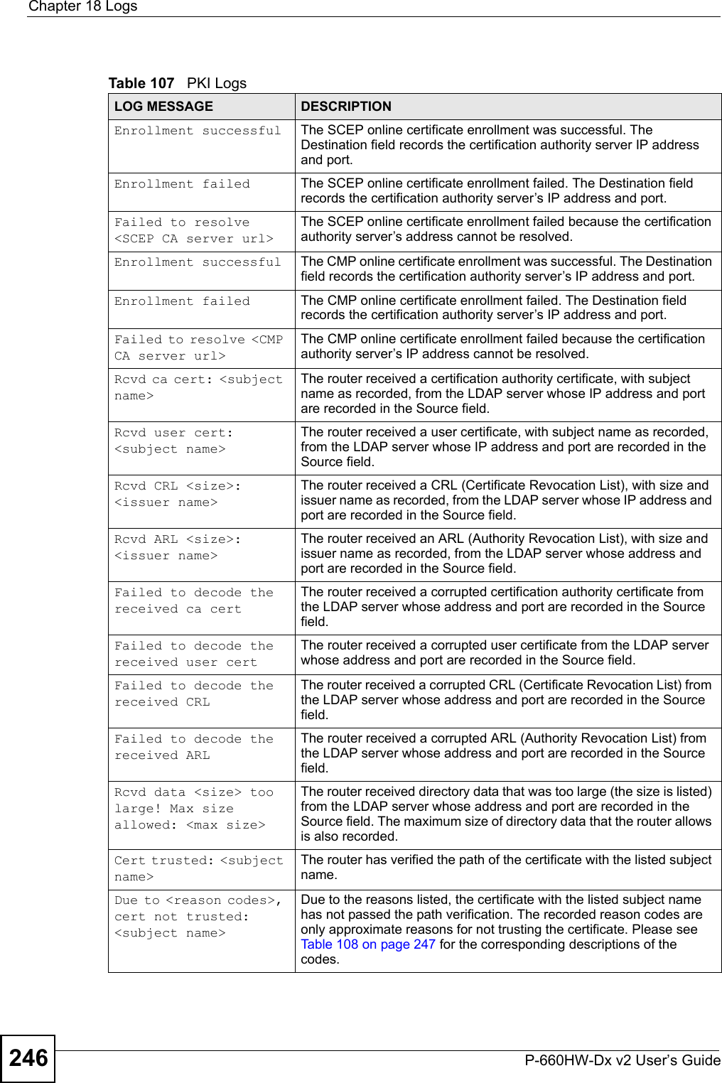
![Chapter 18 LogsP-660HW-Dx v2 User’s Guide242 Table 104 Attack LogsLOG MESSAGE DESCRIPTIONattack [TCP | UDP | IGMP | ESP | GRE | OSPF]The firewall detected a TCP/UDP/IGMP/ESP/GRE/OSPF attack.attack ICMP (type:%d, code:%d)The firewall detected an ICMP attack. For type and code details, see Table 110 on page 248.land [TCP | UDP | IGMP | ESP | GRE | OSPF]The firewall detected a TCP/UDP/IGMP/ESP/GRE/OSPF land attack.land ICMP (type:%d, code:%d)The firewall detected an ICMP land attack. For type and code details, see Table 110 on page 248.ip spoofing - WAN [TCP | UDP | IGMP | ESP | GRE | OSPF]The firewall detected an IP spoofing attack on the WAN port.ip spoofing - WAN ICMP (type:%d, code:%d)The firewall detected an ICMP IP spoofing attack on the WAN port. For type and code details, see Table 110 on page 248.icmp echo: ICMP (type:%d, code:%d)The firewall detected an ICMP echo attack. For type and code details, see Table 110 on page 248.syn flood TCP The firewall detected a TCP syn flood attack.ports scan TCP The firewall detected a TCP port scan attack.teardrop TCP The firewall detected a TCP teardrop attack.teardrop UDP The firewall detected an UDP teardrop attack.teardrop ICMP (type:%d, code:%d)The firewall detected an ICMP teardrop attack. For type and code details, see Table 110 on page 248.illegal command TCP The firewall detected a TCP illegal command attack.NetBIOS TCP The firewall detected a TCP NetBIOS attack.ip spoofing - no routing entry [TCP | UDP | IGMP | ESP | GRE | OSPF]The firewall classified a packet with no source routing entry as an IP spoofing attack.ip spoofing - no routing entry ICMP (type:%d, code:%d)The firewall classified an ICMP packet with no source routing entry as an IP spoofing attack.vulnerability ICMP (type:%d, code:%d)The firewall detected an ICMP vulnerability attack. For type and code details, see Table 110 on page 248.traceroute ICMP (type:%d, code:%d)The firewall detected an ICMP traceroute attack. For type and code details, see Table 110 on page 248.Table 105 IPSec LogsLOG MESSAGE DESCRIPTIONDiscard REPLAY packet The router received and discarded a packet with an incorrect sequence number.Inbound packet authentication failedThe router received a packet that has been altered. A third party may have altered or tampered with the packet.Receive IPSec packet, but no corresponding tunnel existsThe router dropped an inbound packet for which SPI could not find a corresponding phase 2 SA.](https://usermanual.wiki/ZyXEL-Communications/P660HWDXV2.Part3/User-Guide-803152-Page-42.png)
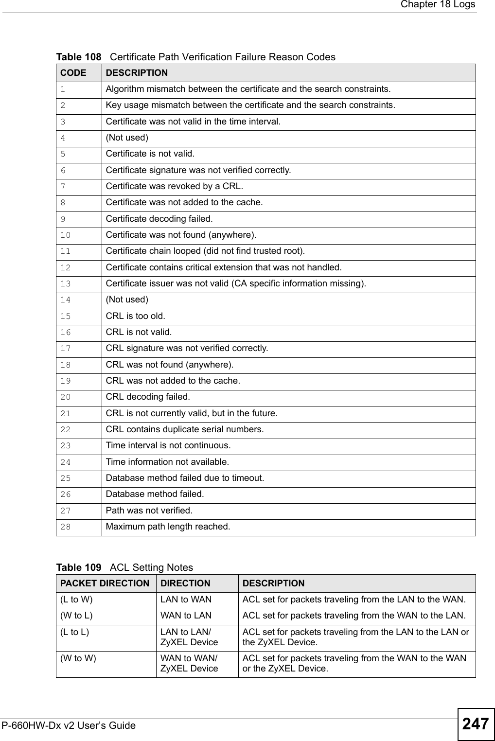
![Chapter 18 LogsP-660HW-Dx v2 User’s Guide244Recv <packet> IKE uses ISAKMP to transmit data. Each ISAKMP packet contains many different types of payloads. All of them show in the LOG. Refer to RFC2408 – ISAKMP for a list of all ISAKMP payload types.Recv <Main or Aggressive> Mode request from <IP> The router received an IKE negotiation request from the peer address specified.Send <Main or Aggressive> Mode request to <IP>The router started negotiation with the peer.Invalid IP <Peer local> / <Peer local>The peer’s “Local IP Address” is invalid.Remote IP <Remote IP> / <Remote IP> conflictsThe security gateway is set to “0.0.0.0” and the router used the peer’s “Local Address” as the router’s “Remote Address”. This information conflicted with static rule #d; thus the connection is not allowed.Phase 1 ID type mismatch This router’s "Peer ID Type" is different from the peer IPSec router's "Local ID Type".Phase 1 ID content mismatch This router’s "Peer ID Content" is different from the peer IPSec router's "Local ID Content".No known phase 1 ID type foundThe router could not find a known phase 1 ID in the connection attempt.ID type mismatch. Local / Peer: <Local ID type/Peer ID type>The phase 1 ID types do not match.ID content mismatch The phase 1 ID contents do not match.Configured Peer ID Content: <Configured Peer ID Content>The phase 1 ID contents do not match and the configured "Peer ID Content" is displayed.Incoming ID Content: <Incoming Peer ID Content>The phase 1 ID contents do not match and the incoming packet's ID content is displayed.Unsupported local ID Type: <%d>The phase 1 ID type is not supported by the router.Build Phase 1 ID The router has started to build the phase 1 ID.Adjust TCP MSS to%d The router automatically changed the TCP Maximum Segment Size value after establishing a tunnel.Rule <%d> input idle time out, disconnectThe tunnel for the listed rule was dropped because there was no inbound traffic within the idle timeout period.XAUTH succeed! Username: <Username>The router used extended authentication to authenticate the listed username.XAUTH fail! Username: <Username>The router was not able to use extended authentication to authenticate the listed username.Rule[%d] Phase 1 negotiation mode mismatchThe listed rule’s IKE phase 1 negotiation mode did not match between the router and the peer.Rule [%d] Phase 1 encryption algorithm mismatchThe listed rule’s IKE phase 1 encryption algorithm did not match between the router and the peer.Rule [%d] Phase 1 authentication algorithm mismatchThe listed rule’s IKE phase 1 authentication algorithm did not match between the router and the peer.Table 106 IKE Logs (continued)LOG MESSAGE DESCRIPTION](https://usermanual.wiki/ZyXEL-Communications/P660HWDXV2.Part3/User-Guide-803152-Page-44.png)
![Chapter 18 LogsP-660HW-Dx v2 User’s Guide 245Rule [%d] Phase 1 authentication method mismatchThe listed rule’s IKE phase 1 authentication method did not match between the router and the peer.Rule [%d] Phase 1 key group mismatchThe listed rule’s IKE phase 1 key group did not match between the router and the peer.Rule [%d] Phase 2 protocol mismatchThe listed rule’s IKE phase 2 protocol did not match between the router and the peer.Rule [%d] Phase 2 encryption algorithm mismatchThe listed rule’s IKE phase 2 encryption algorithm did not match between the router and the peer.Rule [%d] Phase 2 authentication algorithm mismatchThe listed rule’s IKE phase 2 authentication algorithm did not match between the router and the peer.Rule [%d] Phase 2 encapsulation mismatchThe listed rule’s IKE phase 2 encapsulation did not match between the router and the peer.Rule [%d]> Phase 2 pfs mismatchThe listed rule’s IKE phase 2 perfect forward secret (pfs) setting did not match between the router and the peer.Rule [%d] Phase 1 ID mismatch The listed rule’s IKE phase 1 ID did not match between the router and the peer.Rule [%d] Phase 1 hash mismatchThe listed rule’s IKE phase 1 hash did not match between the router and the peer.Rule [%d] Phase 1 preshared key mismatchThe listed rule’s IKE phase 1 pre-shared key did not match between the router and the peer.Rule [%d] Tunnel built successfullyThe listed rule’s IPSec tunnel has been built successfully.Rule [%d] Peer's public key not foundThe listed rule’s IKE phase 1 peer’s public key was not found.Rule [%d] Verify peer's signature failedThe listed rule’s IKE phase 1verification of the peer’s signature failed.Rule [%d] Sending IKE requestIKE sent an IKE request for the listed rule.Rule [%d] Receiving IKE requestIKE received an IKE request for the listed rule.Swap rule to rule [%d] The router changed to using the listed rule.Rule [%d] Phase 1 key length mismatchThe listed rule’s IKE phase 1 key length (with the AES encryption algorithm) did not match between the router and the peer.Rule [%d] phase 1 mismatch The listed rule’s IKE phase 1 did not match between the router and the peer.Rule [%d] phase 2 mismatch The listed rule’s IKE phase 2 did not match between the router and the peer.Rule [%d] Phase 2 key length mismatchThe listed rule’s IKE phase 2 key lengths (with the AES encryption algorithm) did not match between the router and the peer.Table 106 IKE Logs (continued)LOG MESSAGE DESCRIPTION](https://usermanual.wiki/ZyXEL-Communications/P660HWDXV2.Part3/User-Guide-803152-Page-45.png)

![Chapter 21 TroubleshootingP-660HW-Dx v2 User’s Guide 2615Reset the device to its factory defaults, and try to access the ZyXEL Device with the default IP address. See Section 2.3 on page 42. 6If the problem continues, contact the network administrator or vendor, or try one of the advanced suggestions.Advanced Suggestions• Try to access the ZyXEL Device using another service, such as Telnet. If you can access the ZyXEL Device, check the remote management settings and firewall rules to find out why the ZyXEL Device does not respond to HTTP.• If your computer is connected to the WA N port or is connected wirelessly, use a computer that is connected to a LAN/ETHERNET port.VI can see the Login screen, but I cannot log in to the ZyXEL Device.1Make sure you have entered the user name and password correctly. The default password is 1234. This field is case-sensitive, so make sure [Caps Lock] is not on.2You cannot log in to the web configurator while someone is using Telnet to access the ZyXEL Device. Log out of the ZyXEL Device in the other session, or ask the person who is logged in to log out. 3Turn the ZyXEL Device off and on. 4If this does not work, you have to reset the device to its factory defaults. See Section 2.3 on page 42.VI cannot Telnet to the ZyXEL Device. See the troubleshooting suggestions for I cannot see or access the Login screen in the web configurator. Ignore the suggestions about your browser.VI cannot use FTP to upload / download the configuration file. / I cannot use FTP to upload new firmware. See the troubleshooting suggestions for I cannot see or access the Login screen in the web configurator. Ignore the suggestions about your browser.21.3 Internet AccessVI cannot access the Internet.](https://usermanual.wiki/ZyXEL-Communications/P660HWDXV2.Part3/User-Guide-803152-Page-61.png)
![Chapter 21 TroubleshootingP-660HW-Dx v2 User’s Guide2621Check the hardware connections, and make sure the LEDs are behaving as expected. See the Quick Start Guide and Section 1.4 on page 35. 2If your ISP gave you Internet connection information, make sure you entered it correctly in the Network > WAN > Internet Connection screen. These fields are case-sensitive, so make sure [Caps Lock] is not on.3If you are trying to access the Internet wirelessly, make sure the wireless settings in the wireless client are the same as the settings in the AP. 4Disconnect all the cables from your device, and follow the directions in the Quick Start Guide again. 5If the problem continues, contact your ISP. 6VI cannot access the Internet anymore. I had access to the Internet (with the ZyXEL Device), but my Internet connection is not available anymore.1Check the hardware connections, and make sure the LEDs are behaving as expected. See the Quick Start Guide and Section 1.4 on page 35. 2Reboot the ZyXEL Device.3Turn the ZyXEL Device off and on. 4If the problem continues, contact your ISP. VThe Internet connection is slow or intermittent.1There might be a lot of traffic on the network. Try closing some programs that use the Internet, especially peer-to-peer applications.2Check the signal strength. If the signal strength is low, look around to see if there are any devices that might be interfering with the wireless network (for example, microwaves, other wireless networks, and so on).Reboot the ZyXEL Device. 3Turn the ZyXEL Device off and on. 4If the problem continues, contact the network administrator or vendor, or try one of the advanced suggestions.Advanced Suggestions• Check the settings for bandwidth management. If it is disabled, you might consider activating it. If it is enabled, you might consider changing the allocations. • Check the settings for QoS. If it is disabled, you might consider activating it. If it is enabled, you might consider raising or lowering the priority for some applications](https://usermanual.wiki/ZyXEL-Communications/P660HWDXV2.Part3/User-Guide-803152-Page-62.png)

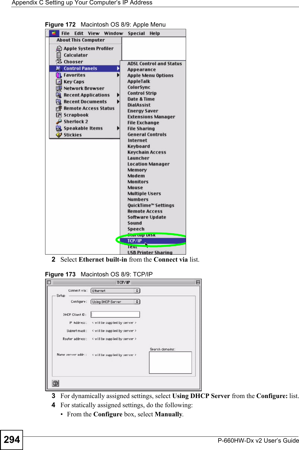
![Appendix C Setting up Your Computer’s IP AddressP-660HW-Dx v2 User’s Guide 293Figure 171 Windows XP: Internet Protocol (TCP/IP) Properties8Click OK to close the Internet Protocol (TCP/IP) Properties window.9Click Close (OK in Windows 2000/NT) to close the Local Area Connection Properties window.10 Close the Network Connections window (Network and Dial-up Connections in Windows 2000/NT).11 Turn on your ZyXEL Device and restart your computer (if prompted).Verifying Settings1Click Start, All Programs, Accessories and then Command Prompt.2In the Command Prompt window, type "ipconfig" and then press [ENTER]. You can also open Network Connections, right-click a network connection, click Status and then click the Support tab.Macintosh OS 8/9 1Click the Apple menu, Control Panel and double-click TCP/IP to open the TCP/IP Control Panel.](https://usermanual.wiki/ZyXEL-Communications/P660HWDXV2.Part3/User-Guide-803152-Page-93.png)
![Appendix C Setting up Your Computer’s IP AddressP-660HW-Dx v2 User’s Guide 299Figure 180 Red Hat 9.0: Dynamic IP Address Setting in ifconfig-eth0 • If you have a static IP address, enter static in the BOOTPROTO= field. Type IPADDR= followed by the IP address (in dotted decimal notation) and type NETMASK= followed by the subnet mask. The following example shows an example where the static IP address is 192.168.1.10 and the subnet mask is 255.255.255.0. Figure 181 Red Hat 9.0: Static IP Address Setting in ifconfig-eth0 2If you know your DNS server IP address(es), enter the DNS server information in the resolv.conf file in the /etc directory. The following figure shows an example where two DNS server IP addresses are specified.Figure 182 Red Hat 9.0: DNS Settings in resolv.conf 3After you edit and save the configuration files, you must restart the network card. Enter ./network restart in the /etc/rc.d/init.d directory. The following figure shows an example.Figure 183 Red Hat 9.0: Restart Ethernet Card DEVICE=eth0ONBOOT=yesBOOTPROTO=dhcpUSERCTL=noPEERDNS=yesTYPE=EthernetDEVICE=eth0ONBOOT=yesBOOTPROTO=staticIPADDR=192.168.1.10NETMASK=255.255.255.0USERCTL=noPEERDNS=yesTYPE=Ethernetnameserver 172.23.5.1nameserver 172.23.5.2[root@localhost init.d]# network restartShutting down interface eth0: [OK]Shutting down loopback interface: [OK]Setting network parameters: [OK]Bringing up loopback interface: [OK]Bringing up interface eth0: [OK]](https://usermanual.wiki/ZyXEL-Communications/P660HWDXV2.Part3/User-Guide-803152-Page-99.png)
![Appendix C Setting up Your Computer’s IP AddressP-660HW-Dx v2 User’s Guide300Verifying SettingsEnter ifconfig in a terminal screen to check your TCP/IP properties. Figure 184 Red Hat 9.0: Checking TCP/IP Properties [root@localhost]# ifconfig eth0 Link encap:Ethernet HWaddr 00:50:BA:72:5B:44 inet addr:172.23.19.129 Bcast:172.23.19.255 Mask:255.255.255.0 UP BROADCAST RUNNING MULTICAST MTU:1500 Metric:1 RX packets:717 errors:0 dropped:0 overruns:0 frame:0 TX packets:13 errors:0 dropped:0 overruns:0 carrier:0 collisions:0 txqueuelen:100 RX bytes:730412 (713.2 Kb) TX bytes:1570 (1.5 Kb) Interrupt:10 Base address:0x1000 [root@localhost]#](https://usermanual.wiki/ZyXEL-Communications/P660HWDXV2.Part3/User-Guide-803152-Page-100.png)