ZyXEL Communications P660HWDXV2 802.11g Wireless ADSL Gateway User Manual SMG 700 User s Guide V1 00 Nov 2004
ZyXEL Communications Corporation 802.11g Wireless ADSL Gateway SMG 700 User s Guide V1 00 Nov 2004
Part3

Chapter 14 Dynamic DNS Setup
P-660HW-Dx v2 User’s Guide 201
Dynamic DNS
server auto
detect IP
Address
Select this option only when there are one or more NAT routers between the ZyXEL
Device and the DDNS server. This feature has the DDNS server automatically
detect and use the IP address of the NAT router that has a public IP address.
Note: The DDNS server may not be able to detect the proper IP
address if there is an HTTP proxy server between the
ZyXEL Device and the DDNS server.
Use specified IP
Address
Type the IP address of the host name(s). Use this if you have a static IP address.
Apply Click Apply to save your changes to the ZyXEL Device.
Cancel Click Cancel to begin configuring this screen afresh.
Table 81 Dynamic DNS (continued)
LABEL DESCRIPTION

Chapter 14 Dynamic DNS Setup
P-660HW-Dx v2 User’s Guide
202

P-660HW-Dx v2 User’s Guide 203
CHAPTER 15
Remote Management
Configuration
This chapter provides information on configuring remote management.
15.1 Remote Management Overview
Remote management allows you to determine which services/protocols can access which
ZyXEL Device interface (if any) from which computers.
"When you configure remote management to allow management from the WAN,
you still need to configure a firewall rule to allow access.
You may manage your ZyXEL Device from a remote location via:
• Internet (WAN only)
• ALL (LAN and WAN)
• LAN only,
• Neither (Disable).
"When you choose WAN only or LAN & WAN, you still need to configure a
firewall rule to allow access. See Appendix E on page 311 for details on
configuring firewall rules.
To disable remote management of a service, select Disable in the corresponding Access
Status field.
You may only have one remote management session running at a time. The ZyXEL Device
automatically disconnects a remote management session of lower priority when another
remote management session of higher priority starts. The priorities for the different types of
remote management sessions are as follows.
1Telnet
2HTTP
Chapter 15 Remote Management Configuration
P-660HW-Dx v2 User’s Guide
204
15.1.1 Remote Management Limitations
Remote management over LAN or WAN will not work when:
• You have disabled that service in one of the remote management screens.
• The IP address in the Secured Client IP field does not match the client IP address. If it
does not match, the ZyXEL Device will disconnect the session immediately.
• There is already another remote management session with an equal or higher priority
running. You may only have one remote management session running at one time.
• There is a firewall rule that blocks it.
• A filter is applied (through the commands) to block a Telnet, FTP or Web service.
15.1.2 Remote Management and NAT
When NAT is enabled:
• Use the ZyXEL Device’s WAN IP address when configuring from the WAN.
• Use the ZyXEL Device’s LAN IP address when configuring from the LAN.
15.1.3 System Timeout
There is a default system management idle timeout of five minutes (three hundred seconds).
The ZyXEL Device automatically logs you out if the management session remains idle for
longer than this timeout period. The management session does not time out when a statistics
screen is polling.
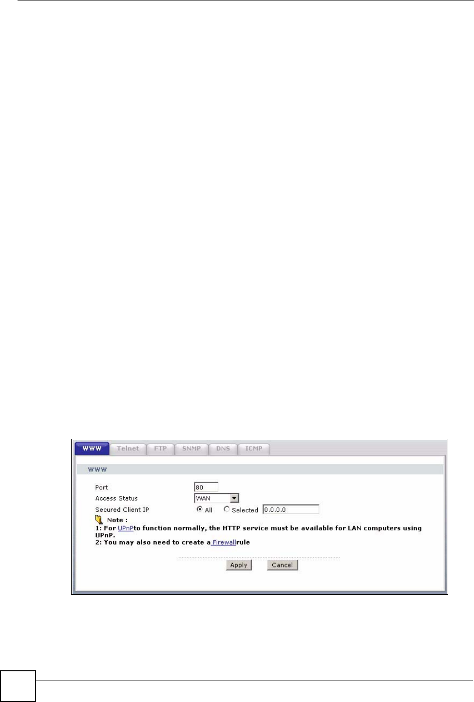
15.2 WWW
To change your ZyXEL Device’s World Wide Web settings, click Advanced > Remote
MGMT to display the WWW screen.
Figure 115 Remote Management: WWW
Chapter 15 Remote Management Configuration
P-660HW-Dx v2 User’s Guide 205
The following table describes the labels in this screen.
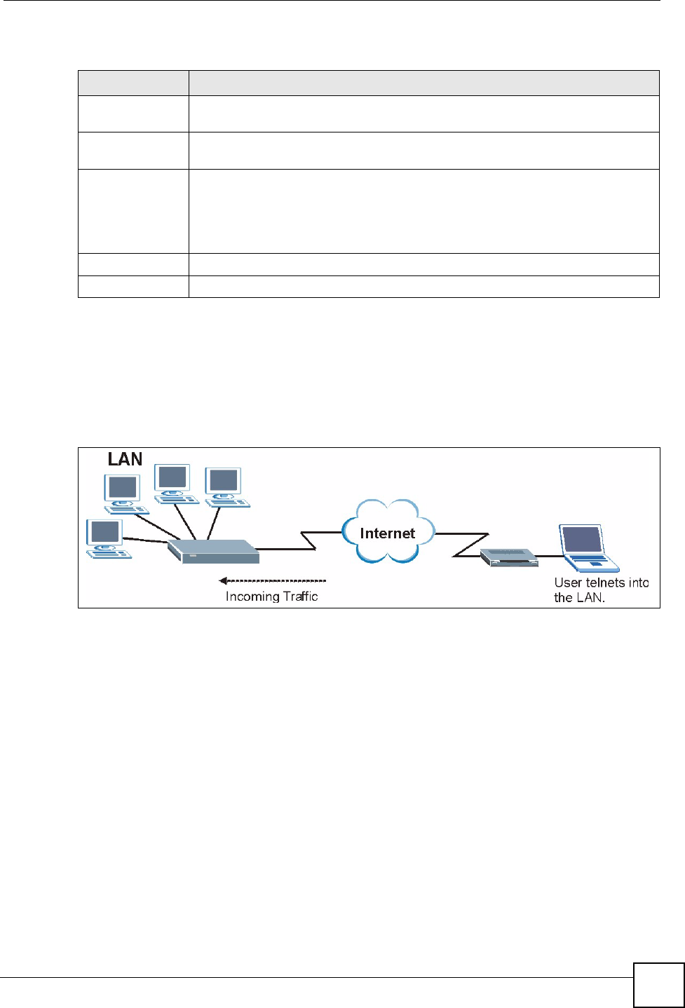
15.3 Telnet
You can configure your ZyXEL Device for remote Telnet access as shown next. The
administrator uses Telnet from a computer on a remote network to access the ZyXEL Device.
Figure 116 Telnet Configuration on a TCP/IP Network
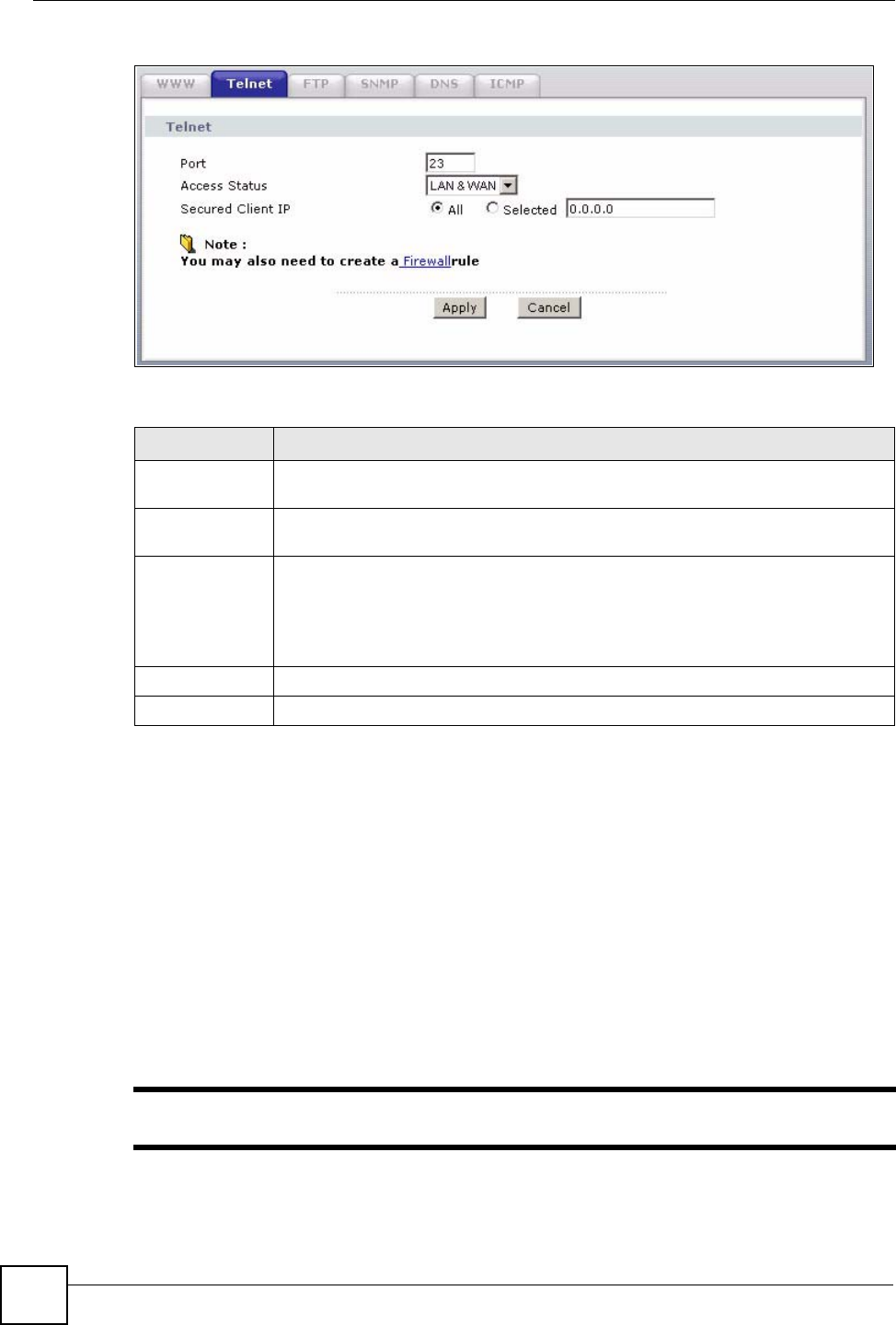
15.4 Configuring Telnet
Click Advanced > Remote MGMT > Te lnet tab to display the screen as shown.
Table 82 Remote Management: WWW
LABEL DESCRIPTION
Port You may change the server port number for a service if needed, however you must
use the same port number in order to use that service for remote management.
Access Status Select the interface(s) through which a computer may access the ZyXEL Device
using this service.
Secured Client IP A secured client is a “trusted” computer that is allowed to communicate with the
ZyXEL Device using this service.
Select All to allow any computer to access the ZyXEL Device using this service.
Choose Selected to just allow the computer with the IP address that you specify to
access the ZyXEL Device using this service.
Apply Click Apply to save your settings to the ZyXEL Device.
Cancel Click Cancel to begin configuring this screen afresh.
Chapter 15 Remote Management Configuration
P-660HW-Dx v2 User’s Guide
206
Figure 117 Remote Management: Telnet
The following table describes the labels in this screen.
15.5 Telnet Login
Use the following steps to Telnet into your ZyXEL Device’s command interpreter.
If your computer is connected to the ZyXEL Device over the Internet, skip to the next step.
Make sure your computer IP address and the ZyXEL Device IP address are on the same
subnet.
3In Windows, click Start (usually in the bottom left corner) and Run. Then type telnet
and the ZyXEL Device’s IP address. For example, enter telnet 192.168.1.1 (the
default IP address).
4Click OK. A login screen displays. Enter the password at the prompts.
"The default password is 1234. The password is case-sensitive.
Table 83 Remote Management: Telnet
LABEL DESCRIPTION
Port You may change the server port number for a service if needed, however you must
use the same port number in order to use that service for remote management.
Access Status Select the interface(s) through which a computer may access the ZyXEL Device
using this service.
Secured Client
IP
A secured client is a “trusted” computer that is allowed to communicate with the
ZyXEL Device using this service.
Select All to allow any computer to access the ZyXEL Device using this service.
Choose Selected to just allow the computer with the IP address that you specify to
access the ZyXEL Device using this service.
Apply Click Apply to save your customized settings and exit this screen.
Cancel Click Cancel to begin configuring this screen afresh.
Chapter 15 Remote Management Configuration
P-660HW-Dx v2 User’s Guide 207
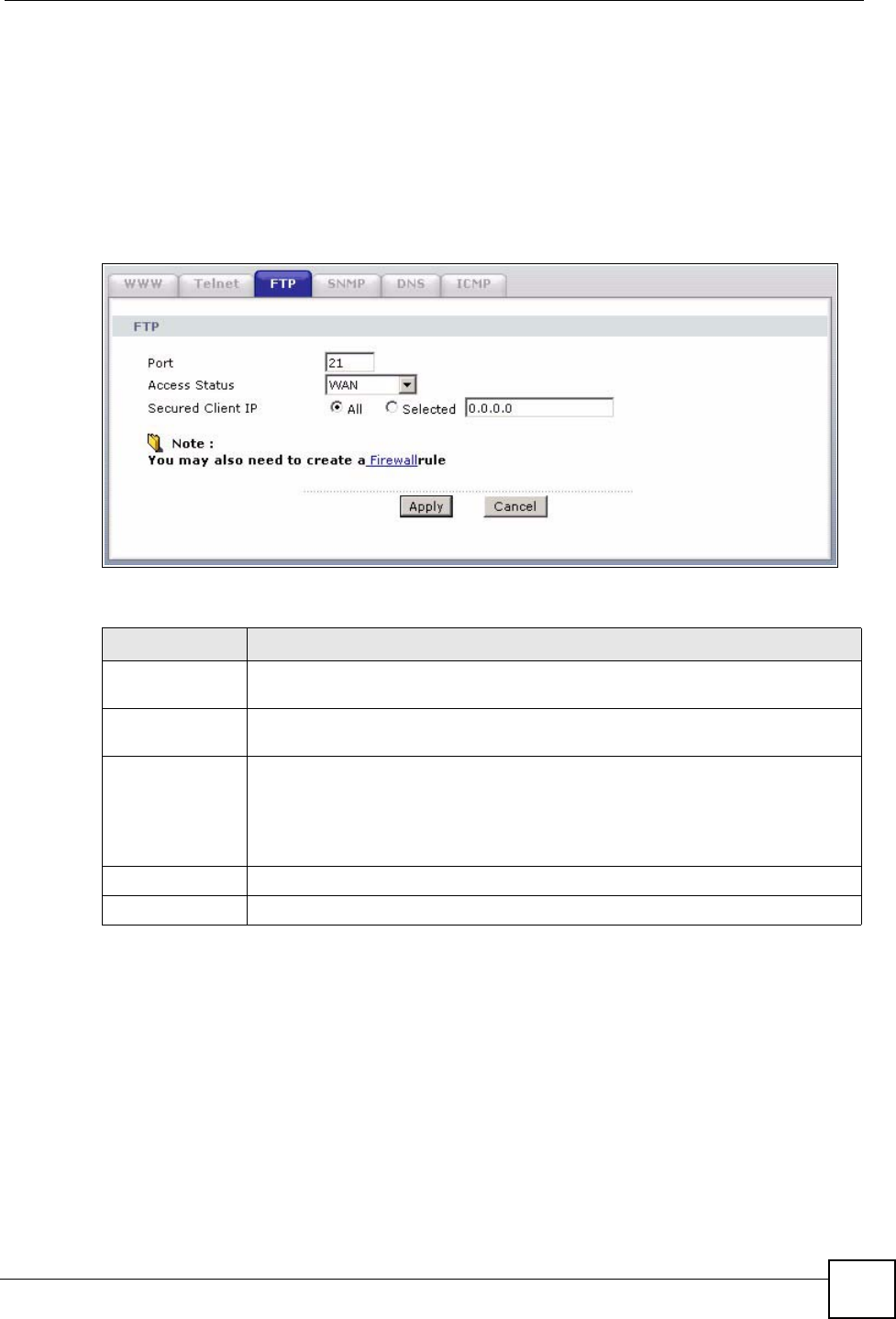
15.6 Configuring FTP
You can upload and download the ZyXEL Device’s firmware and configuration files using
FTP, please see the chapter on firmware and configuration file maintenance for details. To use
this feature, your computer must have an FTP client.
To change your ZyXEL Device’s FTP settings, click Advanced > Remote MGMT > FTP
tab. The screen appears as shown.
Figure 118 Remote Management: FTP
The following table describes the labels in this screen.
15.7 SNMP
Simple Network Management Protocol (SNMP) is a protocol used for exchanging
management information between network devices. SNMP is a member of the TCP/IP
protocol suite. Your ZyXEL Device supports SNMP agent functionality, which allows a
manager station to manage and monitor the ZyXEL Device through the network. The ZyXEL
Device supports SNMP version one (SNMPv1) and version two (SNMPv2). The next figure
illustrates an SNMP management operation.
Table 84 Remote Management: FTP
LABEL DESCRIPTION
Port You may change the server port number for a service if needed, however you must
use the same port number in order to use that service for remote management.
Access Status Select the interface(s) through which a computer may access the ZyXEL Device
using this service.
Secured Client IP A secured client is a “trusted” computer that is allowed to communicate with the
ZyXEL Device using this service.
Select All to allow any computer to access the ZyXEL Device using this service.
Choose Selected to just allow the computer with the IP address that you specify to
access the ZyXEL Device using this service.
Apply Click Apply to save your customized settings and exit this screen.
Cancel Click Cancel to begin configuring this screen afresh.
Chapter 15 Remote Management Configuration
P-660HW-Dx v2 User’s Guide
208
"SNMP is only available if TCP/IP is configured.
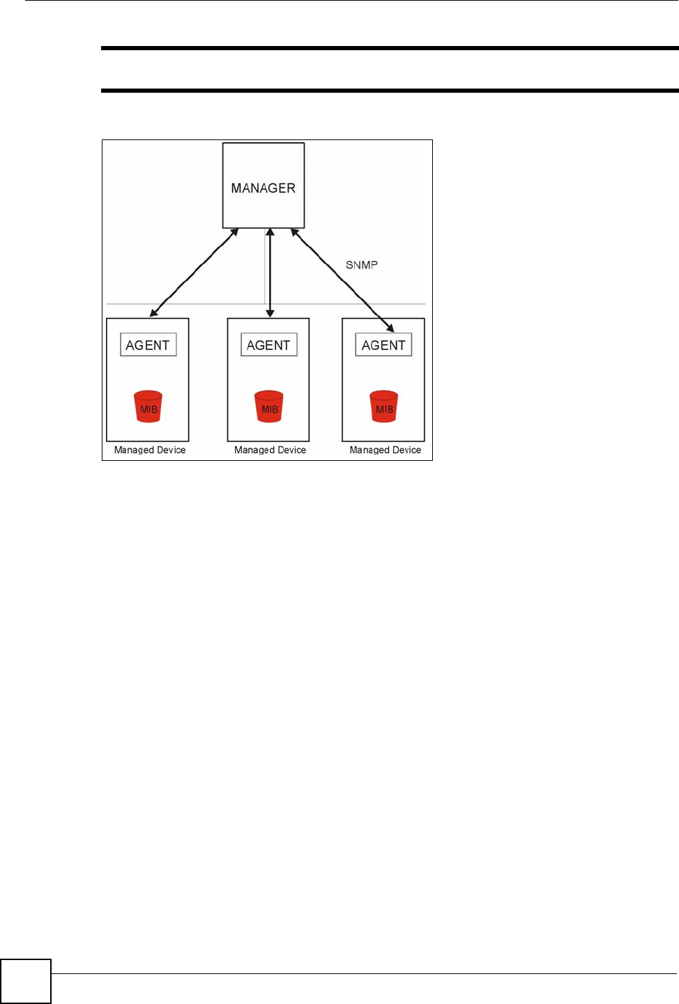
Figure 119 SNMP Management Model
An SNMP managed network consists of two main types of component: agents and a manager.
An agent is a management software module that resides in a managed device (the ZyXEL
Device). An agent translates the local management information from the managed device into
a form compatible with SNMP. The manager is the console through which network
administrators perform network management functions. It executes applications that control
and monitor managed devices.
The managed devices contain object variables/managed objects that define each piece of
information to be collected about a device. Examples of variables include such as number of
packets received, node port status etc. A Management Information Base (MIB) is a collection
of managed objects. SNMP allows a manager and agents to communicate for the purpose of
accessing these objects.
SNMP itself is a simple request/response protocol based on the manager/agent model. The
manager issues a request and the agent returns responses using the following protocol
operations:
• Get - Allows the manager to retrieve an object variable from the agent.
• GetNext - Allows the manager to retrieve the next object variable from a table or list
within an agent. In SNMPv1, when a manager wants to retrieve all elements of a table
from an agent, it initiates a Get operation, followed by a series of GetNext operations.
• Set - Allows the manager to set values for object variables within an agent.
• Trap - Used by the agent to inform the manager of some events.
Chapter 15 Remote Management Configuration
P-660HW-Dx v2 User’s Guide 209
15.7.1 Supported MIBs
The ZyXEL Device supports MIB II that is defined in RFC-1213 and RFC-1215. The focus of
the MIBs is to let administrators collect statistical data and monitor status and performance.
15.7.2 SNMP Traps
The ZyXEL Device will send traps to the SNMP manager when any one of the following
events occurs:
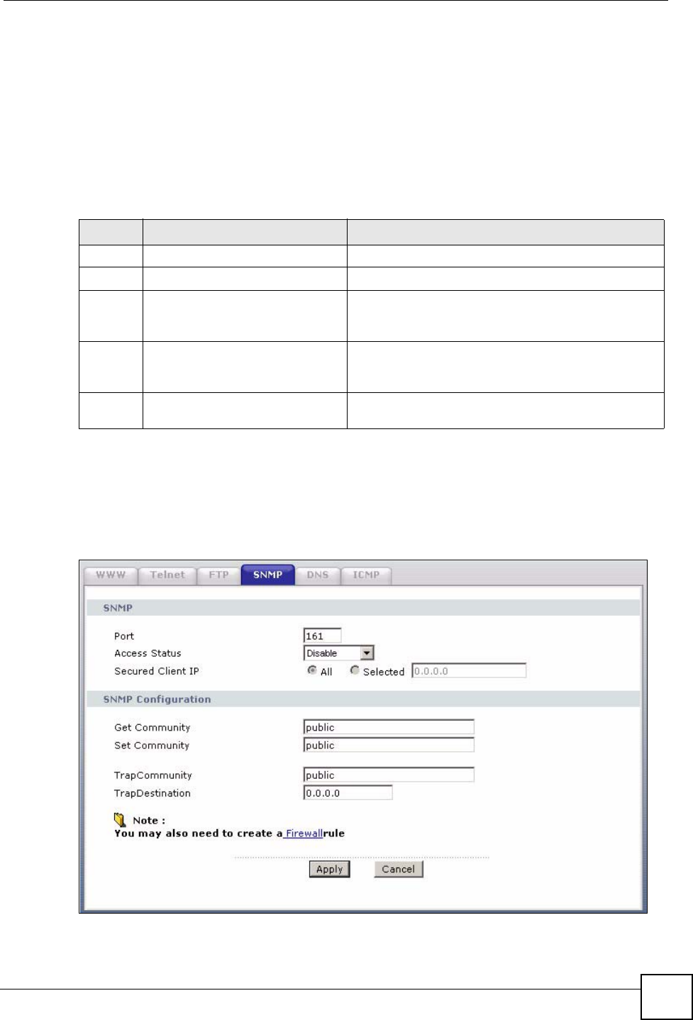
15.7.3 Configuring SNMP
To change your ZyXEL Device’s SNMP settings, click Advanced > Remote MGMT >
SNMP. The screen appears as shown.
Figure 120 Remote Management: SNMP
Table 85 SNMP Traps
TRAP # TRAP NAME DESCRIPTION
0coldStart (defined in RFC-1215)A trap is sent after booting (power on).
1warmStart (defined in RFC-1215)A trap is sent after booting (software reboot).
6whyReboot (defined in ZYXEL-
MIB)
A trap is sent with the reason of restart before
rebooting when the system is going to restart (warm
start).
6a For intentional reboot: A trap is sent with the message "System reboot by
user!" if reboot is done intentionally, (for example,
download new files, CI command "sys reboot", etc.).
6b For fatal error: A trap is sent with the message of the fatal code if the
system reboots because of fatal errors.

Chapter 15 Remote Management Configuration
P-660HW-Dx v2 User’s Guide
210
The following table describes the labels in this screen.
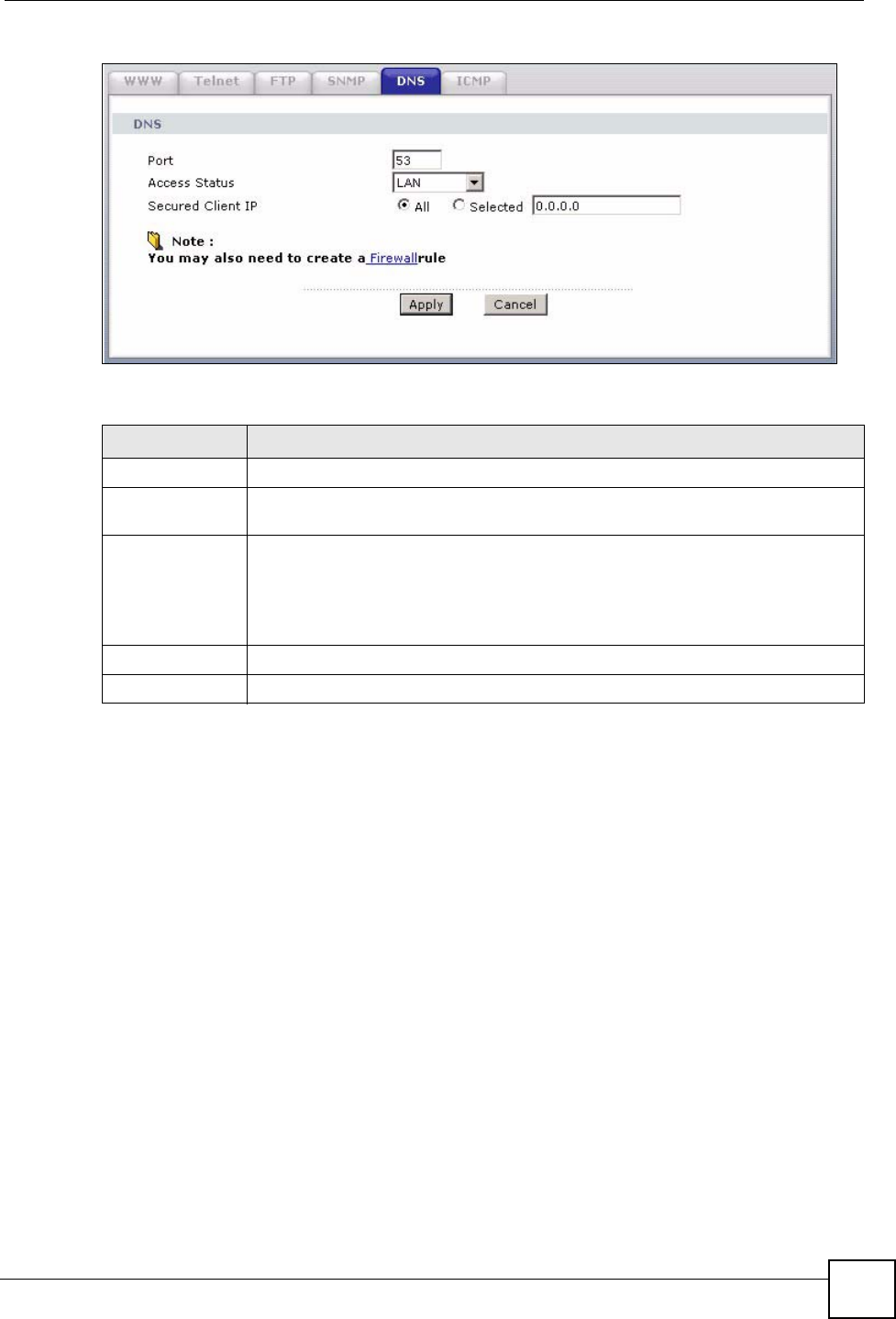
15.8 Configuring DNS
Use DNS (Domain Name System) to map a domain name to its corresponding IP address and
vice versa. Refer to the chapter on LAN for background information.
To change your ZyXEL Device’s DNS settings, click Advanced > Remote MGMT > DNS.
The screen appears as shown. Use this screen to set from which IP address the ZyXEL Device
will accept DNS queries and on which interface it can send them your ZyXEL Device’s DNS
settings.
Table 86 Remote Management: SNMP
LABEL DESCRIPTION
SNMP
Port You may change the server port number for a service if needed, however you
must use the same port number in order to use that service for remote
management.
Access Status Select the interface(s) through which a computer may access the ZyXEL Device
using this service.
Secured Client IP A secured client is a “trusted” computer that is allowed to communicate with the
ZyXEL Device using this service.
Select All to allow any computer to access the ZyXEL Device using this service.
Choose Selected to just allow the computer with the IP address that you specify
to access the ZyXEL Device using this service.
SNMP Configuration
Get Community Enter the Get Community, which is the password for the incoming Get and
GetNext requests from the management station. The default is public and
allows all requests.
Set Community Enter the Set community, which is the password for incoming Set requests
from the management station. The default is public and allows all requests.
TrapCommunity Type the trap community, which is the password sent with each trap to the
SNMP manager. The default is public and allows all requests.
TrapDestination Type the IP address of the station to send your SNMP traps to.
Apply Click Apply to save your customized settings and exit this screen.
Cancel Click Cancel to begin configuring this screen afresh.
Chapter 15 Remote Management Configuration
P-660HW-Dx v2 User’s Guide 211
Figure 121 Remote Management: DNS
The following table describes the labels in this screen.
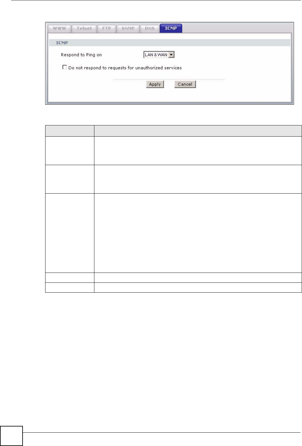
15.9 Configuring ICMP
To change your ZyXEL Device’s security settings, click Advanced > Remote MGMT >
ICMP. The screen appears as shown.
If an outside user attempts to probe an unsupported port on your ZyXEL Device, an ICMP
response packet is automatically returned. This allows the outside user to know the ZyXEL
Device exists. Your ZyXEL Device supports anti-probing, which prevents the ICMP response
packet from being sent. This keeps outsiders from discovering your ZyXEL Device when
unsupported ports are probed.
Table 87 Remote Management: DNS
LABEL DESCRIPTION
Port The DNS service port number is 53.
Access Status Select the interface(s) through which a computer may send DNS queries to the
ZyXEL Device.
Secured Client IP A secured client is a “trusted” computer that is allowed to send DNS queries to the
ZyXEL Device.
Select All to allow any computer to send DNS queries to the ZyXEL Device.
Choose Selected to just allow the computer with the IP address that you specify to
send DNS queries to the ZyXEL Device.
Apply Click Apply to save your customized settings and exit this screen.
Cancel Click Cancel to begin configuring this screen afresh.
Chapter 15 Remote Management Configuration
P-660HW-Dx v2 User’s Guide
212
Figure 122 Remote Management: ICMP
The following table describes the labels in this screen.
Table 88 Remote Management: ICMP
LABEL DESCRIPTION
ICMP Internet Control Message Protocol is a message control and error-reporting
protocol between a host server and a gateway to the Internet. ICMP uses Internet
Protocol (IP) datagrams, but the messages are processed by the TCP/IP software
and directly apparent to the application user.
Respond to Ping
on
The ZyXEL Device will not respond to any incoming Ping requests when Disable is
selected. Select LAN to reply to incoming LAN Ping requests. Select WAN to reply
to incoming WAN Ping requests. Otherwise select LAN & WAN to reply to both
incoming LAN and WAN Ping requests.
Do not respond to
requests for
unauthorized
services
Select this option to prevent hackers from finding the ZyXEL Device by probing for
unused ports. If you select this option, the ZyXEL Device will not respond to port
request(s) for unused ports, thus leaving the unused ports and the ZyXEL Device
unseen. By default this option is not selected and the ZyXEL Device will reply with
an ICMP Port Unreachable packet for a port probe on its unused UDP ports, and a
TCP Reset packet for a port probe on its unused TCP ports.
Note that the probing packets must first traverse the ZyXEL Device's firewall
mechanism before reaching this anti-probing mechanism. Therefore if the firewall
mechanism blocks a probing packet, the ZyXEL Device reacts based on the
corresponding firewall policy to send a TCP reset packet for a blocked TCP packet
or an ICMP port-unreachable packet for a blocked UDP packets or just drop the
packets without sending a response packet.
Apply Click Apply to save your customized settings and exit this screen.
Cancel Click Cancel to begin configuring this screen afresh.

P-660HW-Dx v2 User’s Guide 213
CHAPTER 16
Universal Plug-and-Play (UPnP)
This chapter introduces the UPnP feature in the web configurator.
16.1 Introducing Universal Plug and Play
Universal Plug and Play (UPnP) is a distributed, open networking standard that uses TCP/IP
for simple peer-to-peer network connectivity between devices. A UPnP device can
dynamically join a network, obtain an IP address, convey its capabilities and learn about other
devices on the network. In turn, a device can leave a network smoothly and automatically
when it is no longer in use.
See Section 16.2.1 on page 214 for configuration instructions.
16.1.1 How do I know if I'm using UPnP?
UPnP hardware is identified as an icon in the Network Connections folder (Windows XP).
Each UPnP compatible device installed on your network will appear as a separate icon.
Selecting the icon of a UPnP device will allow you to access the information and properties of
that device.
16.1.2 NAT Traversal
UPnP NAT traversal automates the process of allowing an application to operate through
NAT. UPnP network devices can automatically configure network addressing, announce their
presence in the network to other UPnP devices and enable exchange of simple product and
service descriptions. NAT traversal allows the following:
• Dynamic port mapping
• Learning public IP addresses
• Assigning lease times to mappings
Windows Messenger is an example of an application that supports NAT traversal and UPnP.
See the NAT chapter for more information on NAT.
16.1.3 Cautions with UPnP
The automated nature of NAT traversal applications in establishing their own services and
opening firewall ports may present network security issues. Network information and
configuration may also be obtained and modified by users in some network environments.
Chapter 16 Universal Plug-and-Play (UPnP)
P-660HW-Dx v2 User’s Guide
214
When a UPnP device joins a network, it announces its presence with a multicast message. For
security reasons, the ZyXEL Device allows multicast messages only on the LAN.
All UPnP-enabled devices may communicate freely with each other without additional
configuration. Disable UPnP if this is not your intention.
You must have IIS (Internet Information Services) enabled on the Windows web server for
UPnP to work.
16.2 UPnP and ZyXEL
ZyXEL has achieved UPnP certification from the Universal Plug and Play Forum UPnP™
Implementers Corp. (UIC). ZyXEL's UPnP implementation supports IGD 1.0 (Internet
Gateway Device).
See the following sections for examples of installing and using UPnP.
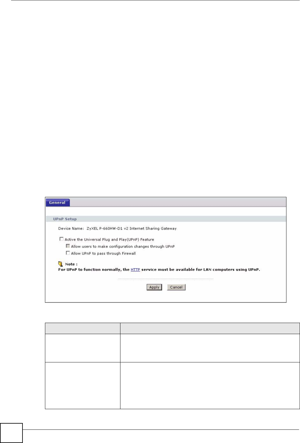
16.2.1 Configuring UPnP
Click Advanced > UPnP to display the screen shown next.
See Section 16.1 on page 213 for more information.
Figure 123 Configuring UPnP
The following table describes the fields in this screen.
Table 89 Configuring UPnP
LABEL DESCRIPTION
Active the Universal Plug
and Play (UPnP) Feature
Select this check box to activate UPnP. Be aware that anyone could
use a UPnP application to open the web configurator's login screen
without entering the ZyXEL Device's IP address (although you must still
enter the password to access the web configurator).
Allow users to make
configuration changes
through UPnP
Select this check box to allow UPnP-enabled applications to
automatically configure the ZyXEL Device so that they can
communicate through the ZyXEL Device, for example by using NAT
traversal, UPnP applications automatically reserve a NAT forwarding
port in order to communicate with another UPnP enabled device; this
eliminates the need to manually configure port forwarding for the UPnP
enabled application.
Chapter 16 Universal Plug-and-Play (UPnP)
P-660HW-Dx v2 User’s Guide 215
16.3 Installing UPnP in Windows Example
This section shows how to install UPnP in Windows Me and Windows XP.
16.3.1 Installing UPnP in Windows Me
Follow the steps below to install the UPnP in Windows Me.
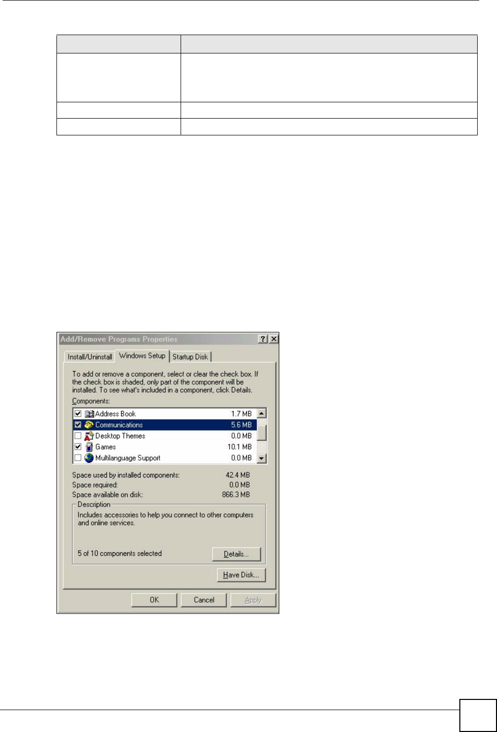
1Click Start and Control Panel. Double-click Add/Remove Programs.
2Click on the Windows Setup tab and select Communication in the Components
selection box. Click Details.
Figure 124 Add/Remove Programs: Windows Setup: Communication
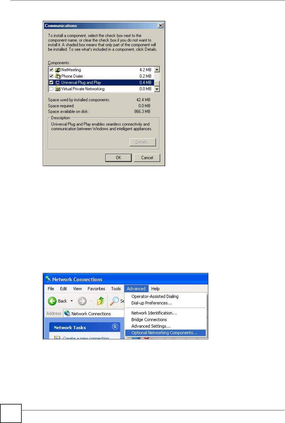
3In the Communications window, select the Universal Plug and Play check box in the
Components selection box.
Allow UPnP to pass through
Firewall
Select this check box to allow traffic from UPnP-enabled applications to
bypass the firewall.
Clear this check box to have the firewall block all UPnP application
packets (for example, MSN packets).
Apply Click Apply to save the setting to the ZyXEL Device.
Cancel Click Cancel to return to the previously saved settings.
Table 89 Configuring UPnP
LABEL DESCRIPTION
Chapter 16 Universal Plug-and-Play (UPnP)
P-660HW-Dx v2 User’s Guide
216
Figure 125 Add/Remove Programs: Windows Setup: Communication: Components
4Click OK to go back to the Add/Remove Programs Properties window and click
Next.
5Restart the computer when prompted.
16.3.2 Installing UPnP in Windows XP
Follow the steps below to install the UPnP in Windows XP.
1Click start and Control Panel.
2Double-click Network Connections.
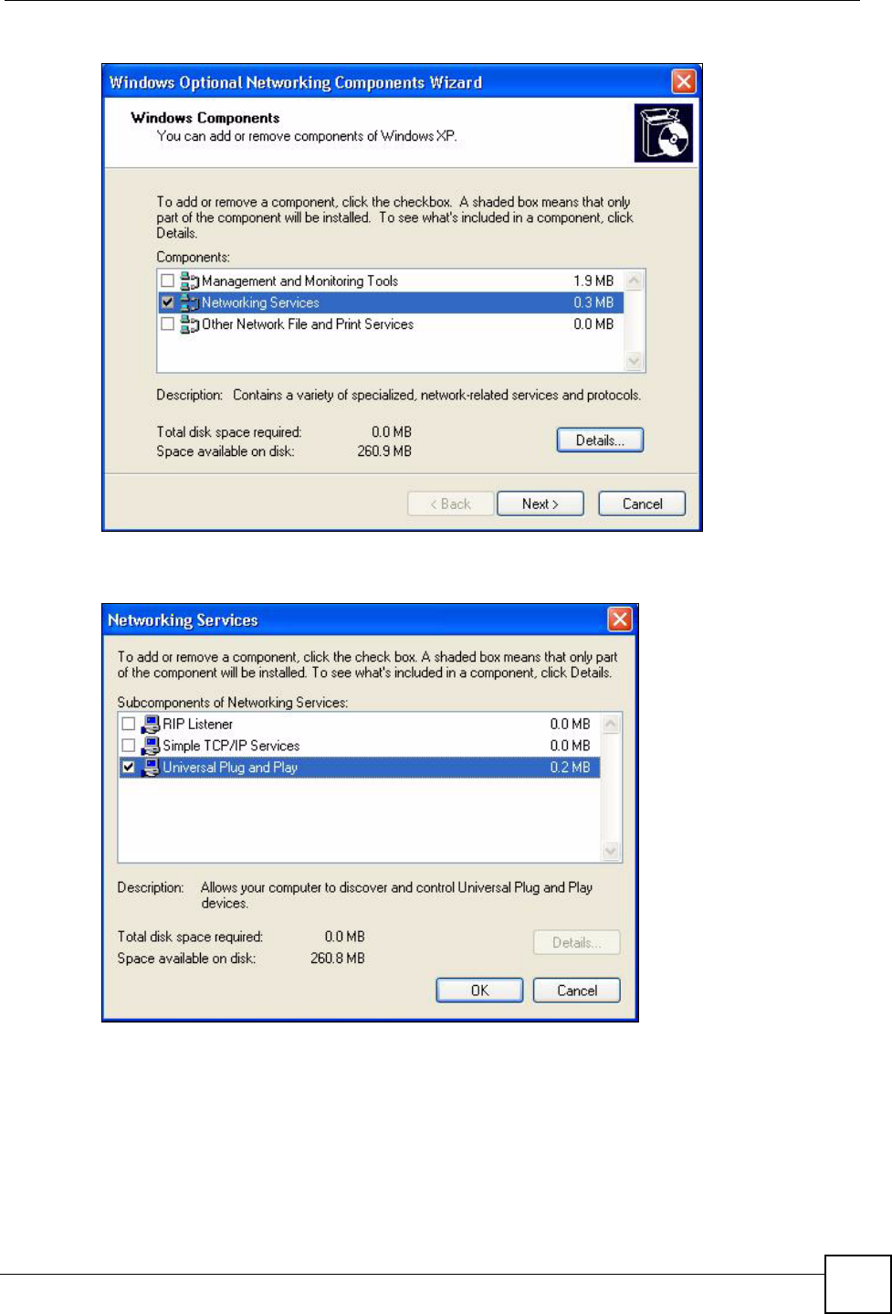
3In the Network Connections window, click Advanced in the main menu and select
Optional Networking Components ….
Figure 126 Network Connections
4The Windows Optional Networking Components Wizard window displays. Select
Networking Service in the Components selection box and click Details.
Chapter 16 Universal Plug-and-Play (UPnP)
P-660HW-Dx v2 User’s Guide 217
Figure 127 Windows Optional Networking Components Wizard
5In the Networking Services window, select the Universal Plug and Play check box.
Figure 128 Networking Services
6Click OK to go back to the Windows Optional Networking Component Wizard
window and click Next.
16.4 Using UPnP in Windows XP Example
This section shows you how to use the UPnP feature in Windows XP. You must already have
UPnP installed in Windows XP and UPnP activated on the ZyXEL Device.
Chapter 16 Universal Plug-and-Play (UPnP)
P-660HW-Dx v2 User’s Guide
218
Make sure the computer is connected to a LAN port of the ZyXEL Device. Turn on your
computer and the ZyXEL Device.
16.4.1 Auto-discover Your UPnP-enabled Network Device
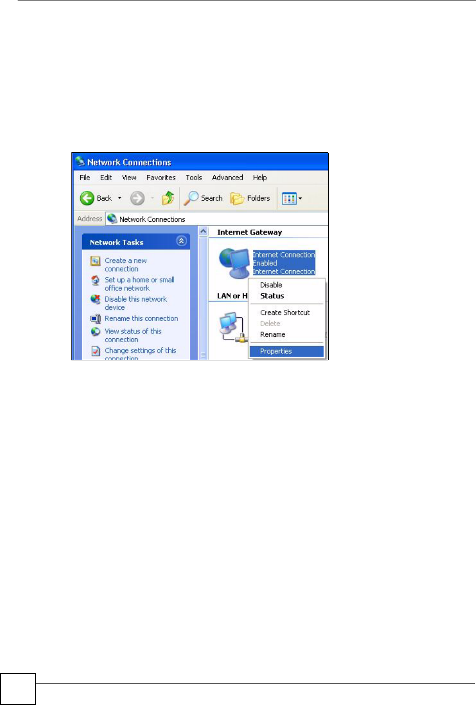
1Click start and Control Panel. Double-click Network Connections. An icon displays
under Internet Gateway.
2Right-click the icon and select Properties.
Figure 129 Network Connections
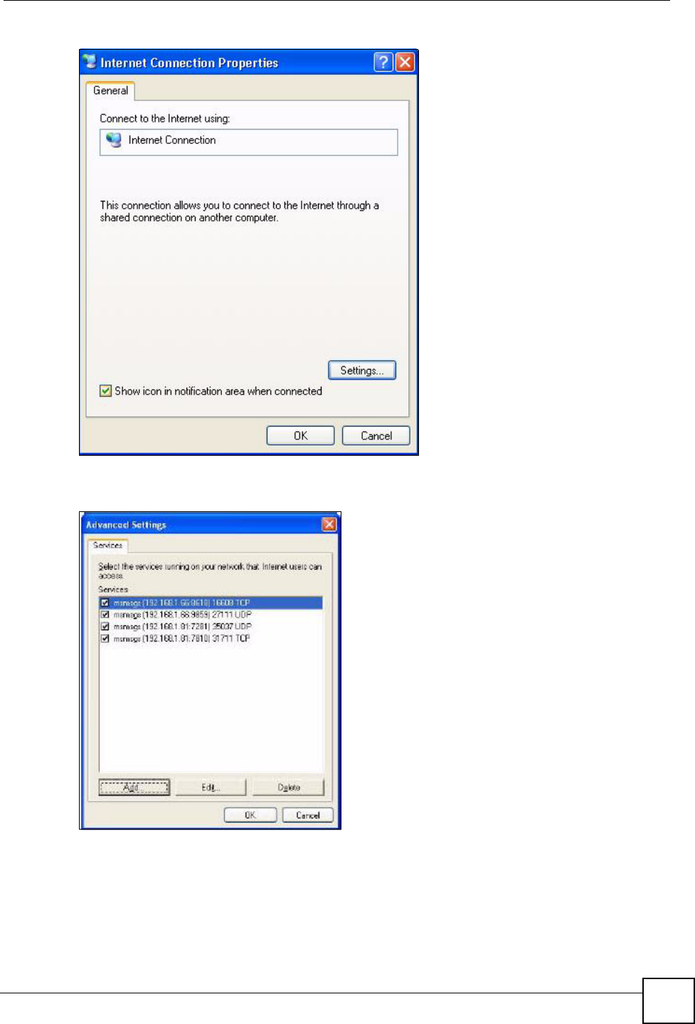
3In the Internet Connection Properties window, click Settings to see the port mappings
there were automatically created.
Chapter 16 Universal Plug-and-Play (UPnP)
P-660HW-Dx v2 User’s Guide 219
Figure 130 Internet Connection Properties
4You may edit or delete the port mappings or click Add to manually add port mappings.
Figure 131 Internet Connection Properties: Advanced Settings
Chapter 16 Universal Plug-and-Play (UPnP)
P-660HW-Dx v2 User’s Guide
220
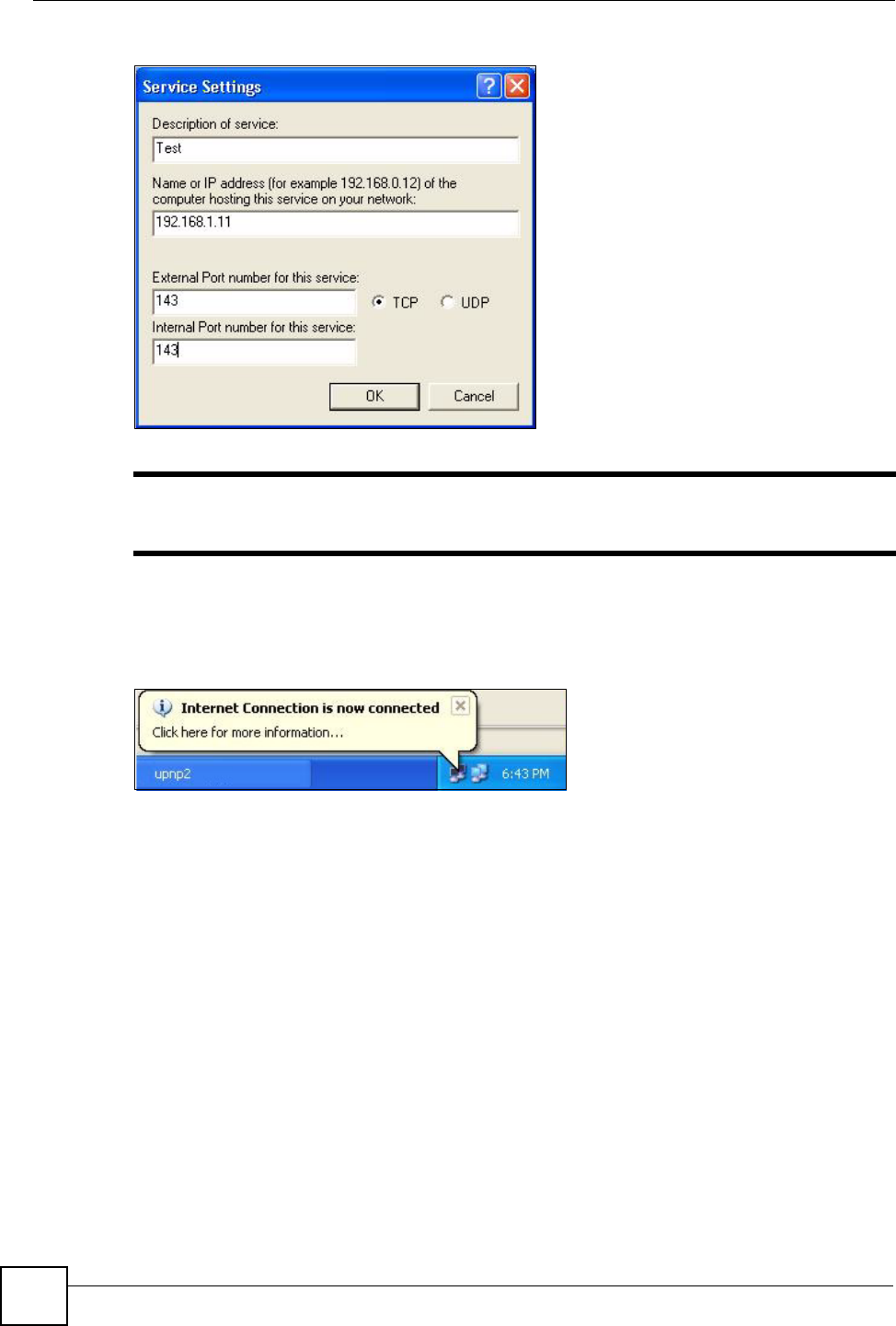
Figure 132 Internet Connection Properties: Advanced Settings: Add
"When the UPnP-enabled device is disconnected from your computer, all port
mappings will be deleted automatically.
5Select Show icon in notification area when connected option and click OK. An icon
displays in the system tray.
Figure 133 System Tray Icon
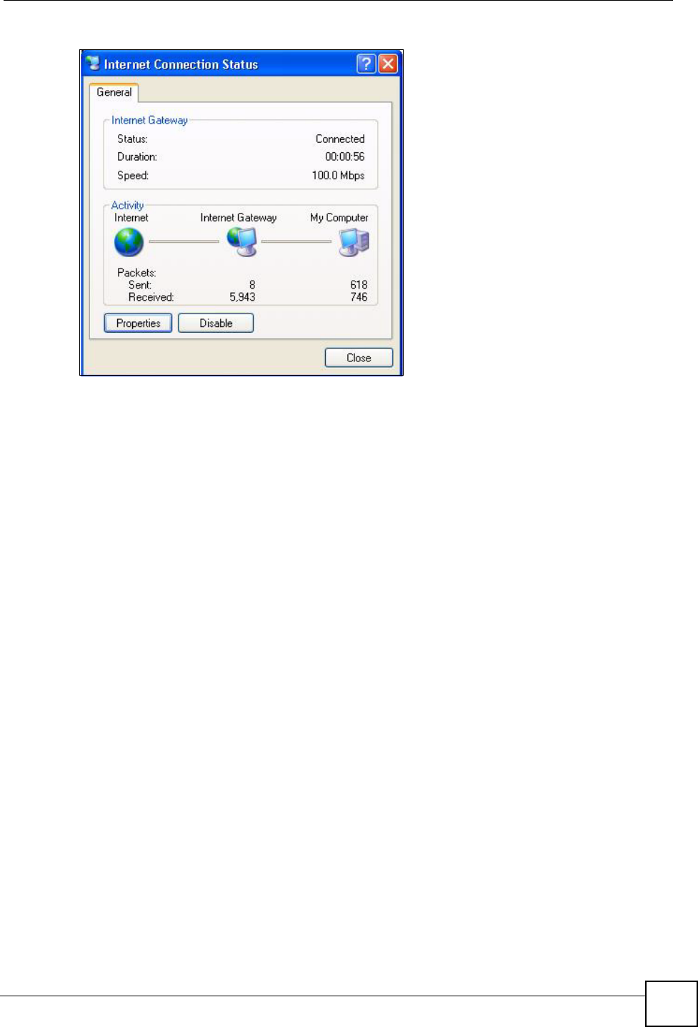
6Double-click on the icon to display your current Internet connection status.
Chapter 16 Universal Plug-and-Play (UPnP)
P-660HW-Dx v2 User’s Guide 221
Figure 134 Internet Connection Status
16.4.2 Web Configurator Easy Access
With UPnP, you can access the web-based configurator on the ZyXEL Device without finding
out the IP address of the ZyXEL Device first. This comes helpful if you do not know the IP
address of the ZyXEL Device.
Follow the steps below to access the web configurator.
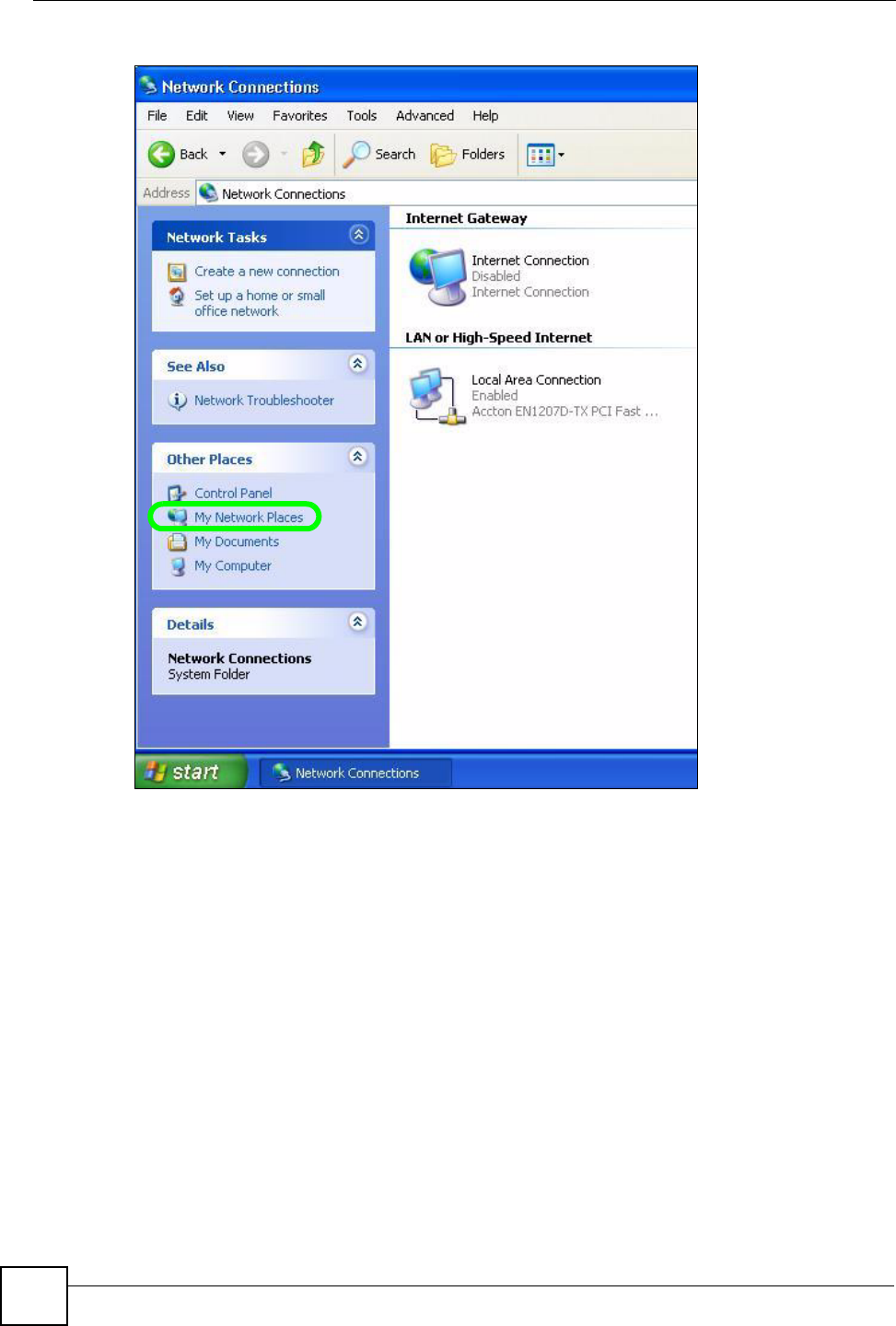
1Click Start and then Control Panel.
2Double-click Network Connections.
3Select My Network Places under Other Places.
Chapter 16 Universal Plug-and-Play (UPnP)
P-660HW-Dx v2 User’s Guide
222
Figure 135 Network Connections
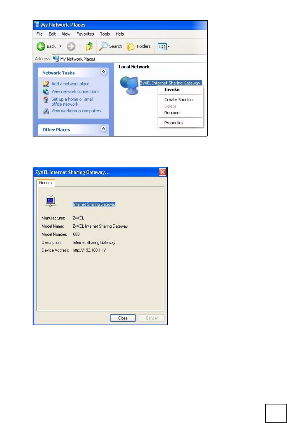
4An icon with the description for each UPnP-enabled device displays under Local
Network.
5Right-click on the icon for your ZyXEL Device and select Invoke. The web configurator
login screen displays.
Chapter 16 Universal Plug-and-Play (UPnP)
P-660HW-Dx v2 User’s Guide 223
Figure 136 Network Connections: My Network Places
6Right-click on the icon for your ZyXEL Device and select Properties. A properties
window displays with basic information about the ZyXEL Device.
Figure 137 Network Connections: My Network Places: Properties: Example

Chapter 16 Universal Plug-and-Play (UPnP)
P-660HW-Dx v2 User’s Guide
224

225
PART VI
Maintenance and
Troubleshooting
System (227)
Logs (233)
Tools (251)
Diagnostic (257)
Troubleshooting (259)

226

P-660HW-Dx v2 User’s Guide 227
CHAPTER 17
System
Use this screen to configure the ZyXEL Device’s time and date settings.
17.1 General Setup
17.1.1 General Setup and System Name
General Setup contains administrative and system-related information. System Name is for
identification purposes. However, because some ISPs check this name you should enter your
computer's "Computer Name".
• In Windows 95/98 click Start, Settings, Control Panel, Network. Click the
Identification tab, note the entry for the Computer Name field and enter it as the System
Name.
• In Windows 2000, click Start, Settings, Control Panel and then double-click System.
Click the Network Identification tab and then the Properties button. Note the entry for
the Computer name field and enter it as the System Name.
• In Windows XP, click start, My Computer, View system information and then click the
Computer Name tab. Note the entry in the Full computer name field and enter it as the
ZyXEL Device System Name.
17.1.2 General Setup
The Domain Name entry is what is propagated to the DHCP clients on the LAN. If you leave
this blank, the domain name obtained by DHCP from the ISP is used. While you must enter
the host name (System Name), the domain name can be assigned from the ZyXEL Device via
DHCP.
Click Maintenance > System to open the General screen.
Chapter 17 System
P-660HW-Dx v2 User’s Guide
228
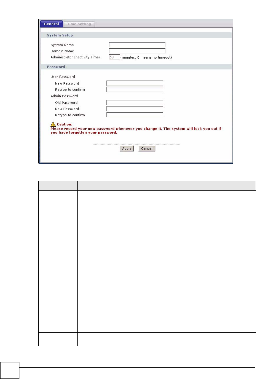
Figure 138 System General Setup
The following table describes the labels in this screen.
Table 90 System General Setup
LABEL DESCRIPTION
General Setup
System Name Choose a descriptive name for identification purposes. It is recommended you enter
your computer’s “Computer name” in this field. This name can be up to 30
alphanumeric characters long. Spaces are not allowed, but dashes “-” and
underscores "_" are accepted.
Domain Name Enter the domain name (if you know it) here. If you leave this field blank, the ISP
may assign a domain name via DHCP.
The domain name entered by you is given priority over the ISP assigned domain
name.
Administrator
Inactivity Timer
Type how many minutes a management session can be left idle before the session
times out. The default is 5 minutes. After it times out you have to log in with your
password again. Very long idle timeouts may have security risks. A value of "0"
means a management session never times out, no matter how long it has been left
idle (not recommended).
Password
User Password If you log in with the user password, you can only view the ZyXEL Device status.
The default user password is user.
New Password Type your new system password (up to 30 characters). Note that as you type a
password, the screen displays a (*) for each character you type. After you change
the password, use the new password to access the ZyXEL Device.
Retype to
Confirm
Type the new password again for confirmation.
Admin
Password
If you log in with the admin password, you can configure the advanced features as
well as the wizard setup on the ZyXEL Device.
Chapter 17 System
P-660HW-Dx v2 User’s Guide 229
17.2 Time Setting
To change your ZyXEL Device’s time and date, click Maintenance > System > Time
Setting. The screen appears as shown. Use this screen to configure the ZyXEL Device’s time
based on your local time zone.
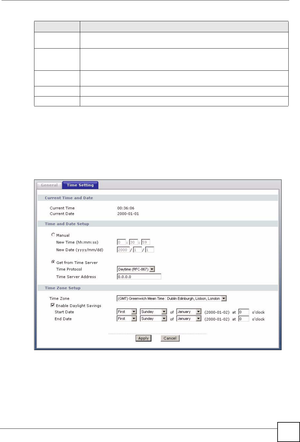
Figure 139 System Time Setting
Old Password Type the default admin password (1234) or the existing password you use to
access the system for configuring advanced features.
New Password Type your new system password (up to 30 characters). Note that as you type a
password, the screen displays a (*) for each character you type. After you change
the password, use the new password to access the ZyXEL Device.
Retype to
Confirm
Type the new password again for confirmation.
Apply Click Apply to save your changes to the ZyXEL Device.
Cancel Click Cancel to begin configuring this screen afresh.
Table 90 System General Setup
LABEL DESCRIPTION

Chapter 17 System
P-660HW-Dx v2 User’s Guide
230
The following table describes the fields in this screen.
Table 91 System Time Setting
LABEL DESCRIPTION
Current Time and
Date
Current Time This field displays the time of your ZyXEL Device.
Each time you reload this page, the ZyXEL Device synchronizes the time with the
time server.
Current Date This field displays the date of your ZyXEL Device.
Each time you reload this page, the ZyXEL Device synchronizes the date with the
time server.
Time and Date
Setup
Manual Select this radio button to enter the time and date manually. If you configure a
new time and date, Time Zone and Daylight Saving at the same time, the new
time and date you entered has priority and the Time Zone and Daylight Saving
settings do not affect it.
New Time
(hh:mm:ss)
This field displays the last updated time from the time server or the last time
configured manually.
When you set Time and Date Setup to Manual, enter the new time in this field
and then click Apply.
New Date
(yyyy/mm/dd)
This field displays the last updated date from the time server or the last date
configured manually.
When you set Time and Date Setup to Manual, enter the new date in this field
and then click Apply.
Get from Time
Server
Select this radio button to have the ZyXEL Device get the time and date from the
time server you specified below.
Time Protocol Select the time service protocol that your time server uses. Not all time servers
support all protocols, so you may have to check with your ISP/network
administrator or use trial and error to find a protocol that works.
The main difference between them is the format.
Daytime (RFC 867) format is day/month/year/time zone of the server.
Time (RFC 868) format displays a 4-byte integer giving the total number of
seconds since 1970/1/1 at 0:0:0.
The default, NTP (RFC 1305), is similar to Time (RFC 868).
Time Server
Address
Enter the IP address or URL (up to 20 extended ASCII characters in length) of
your time server. Check with your ISP/network administrator if you are unsure of
this information.
Time Zone Setup
Time Zone Choose the time zone of your location. This will set the time difference between
your time zone and Greenwich Mean Time (GMT).
Enable Daylight
Savings
Daylight saving is a period from late spring to early fall when many countries set
their clocks ahead of normal local time by one hour to give more daytime light in
the evening.
Select this option if you use Daylight Saving Time.

Chapter 17 System
P-660HW-Dx v2 User’s Guide 231
Start Date Configure the day and time when Daylight Saving Time starts if you selected
Enable Daylight Saving. The o'clock field uses the 24 hour format. Here are a
couple of examples:
Daylight Saving Time starts in most parts of the United States on the first Sunday
of April. Each time zone in the United States starts using Daylight Saving Time at
2 A.M. local time. So in the United States you would select First, Sunday, April
and type 2 in the o'clock field.
Daylight Saving Time starts in the European Union on the last Sunday of March.
All of the time zones in the European Union start using Daylight Saving Time at
the same moment (1 A.M. GMT or UTC). So in the European Union you would
select Last, Sunday, March. The time you type in the o'clock field depends on
your time zone. In Germany for instance, you would type 2 because Germany's
time zone is one hour ahead of GMT or UTC (GMT+1).
End Date Configure the day and time when Daylight Saving Time ends if you selected
Enable Daylight Saving. The o'clock field uses the 24 hour format. Here are a
couple of examples:
Daylight Saving Time ends in the United States on the last Sunday of October.
Each time zone in the United States stops using Daylight Saving Time at 2 A.M.
local time. So in the United States you would select Last, Sunday, October and
type 2 in the o'clock field.
Daylight Saving Time ends in the European Union on the last Sunday of October.
All of the time zones in the European Union stop using Daylight Saving Time at
the same moment (1 A.M. GMT or UTC). So in the European Union you would
select Last, Sunday, October. The time you type in the o'clock field depends on
your time zone. In Germany for instance, you would type 2 because Germany's
time zone is one hour ahead of GMT or UTC (GMT+1).
Apply Click Apply to save your changes to the ZyXEL Device.
Cancel Click Cancel to begin configuring this screen afresh.
Table 91 System Time Setting (continued)
LABEL DESCRIPTION

Chapter 17 System
P-660HW-Dx v2 User’s Guide
232

P-660HW-Dx v2 User’s Guide 233
CHAPTER 18
Logs
This chapter contains information about configuring general log settings and viewing the
ZyXEL Device’s logs. Refer to the appendix for example log message explanations.
18.1 Logs Overview
The web configurator allows you to choose which categories of events and/or alerts to have
the ZyXEL Device log and then display the logs or have the ZyXEL Device send them to an
administrator (as e-mail) or to a syslog server.
18.1.1 Alerts and Logs
An alert is a type of log that warrants more serious attention. They include system errors,
attacks (access control) and attempted access to blocked web sites. Some categories such as
System Errors consist of both logs and alerts. You may differentiate them by their color in the
View Log screen. Alerts display in red and logs display in black.
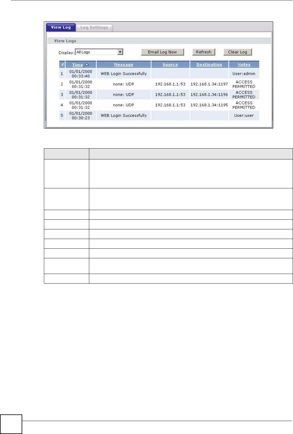
18.2 Viewing the Logs
Click Maintenance > Logs to open the View Log screen. Use the View Log screen to see the
logs for the categories that you selected in the Log Settings screen (see Section 18.3 on page
234).
Log entries in red indicate alerts. The log wraps around and deletes the old entries after it fills.
Click a column heading to sort the entries. A triangle indicates ascending or descending sort
order.
Chapter 18 Logs
P-660HW-Dx v2 User’s Guide
234
Figure 140 View Log
The following table describes the fields in this screen.
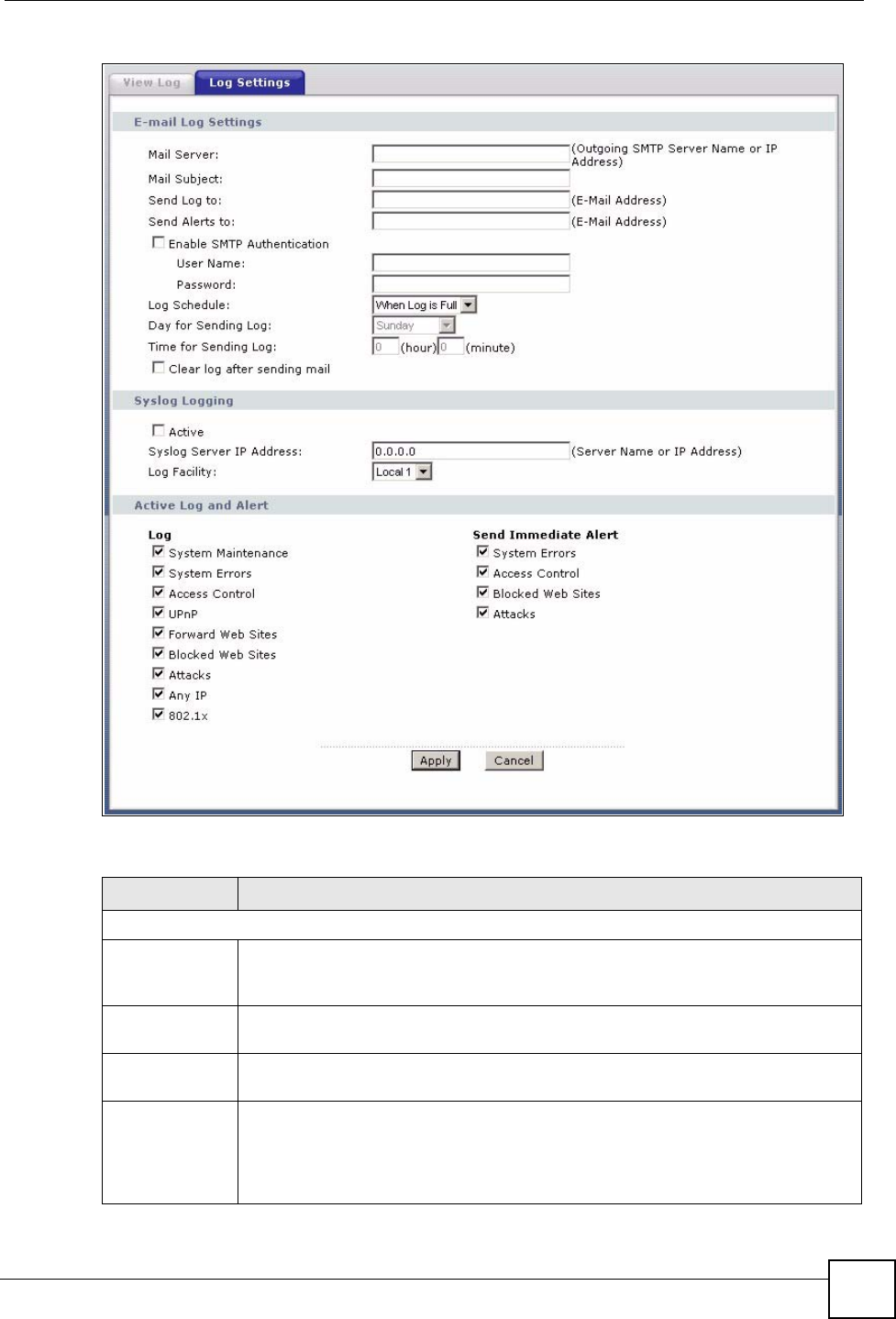
18.3 Configuring Log Settings
Use the Log Settings screen to configure to where the ZyXEL Device is to send logs; the
schedule for when the ZyXEL Device is to send the logs and which logs and/or immediate
alerts the ZyXEL Device is to record. See Section 18.1 on page 233 for more information.
To change your ZyXEL Device’s log settings, click Maintenance > Logs > Log Settings. The
screen appears as shown.
Alerts are e-mailed as soon as they happen. Logs may be e-mailed as soon as the log is full.
Selecting many alert and/or log categories (especially Access Control) may result in many e-
mails being sent.
Table 92 View Log
LABEL DESCRIPTION
Display The categories that you select in the Log Settings screen display in the drop-down
list box.
Select a category of logs to view; select All Logs to view logs from all of the log
categories that you selected in the Log Settings page.
Email Log Now Click Email Log Now to send the log screen to the e-mail address specified in the
Log Settings page (make sure that you have first filled in the E-mail Log Settings
fields in Log Settings).
Refresh Click Refresh to renew the log screen.
Clear Log Click Clear Log to delete all the logs.
Time This field displays the time the log was recorded.
Message This field states the reason for the log.
Source This field lists the source IP address and the port number of the incoming packet.
Destination This field lists the destination IP address and the port number of the incoming
packet.
Notes This field displays additional information about the log entry.
Chapter 18 Logs
P-660HW-Dx v2 User’s Guide 235
Figure 141 Log Settings
The following table describes the fields in this screen.
Table 93 Log Settings
LABEL DESCRIPTION
E-mail Log Settings
Mail Server Enter the server name or the IP address of the mail server for the e-mail addresses
specified below. If this field is left blank, logs and alert messages will not be sent via
E-mail.
Mail Subject Type a title that you want to be in the subject line of the log e-mail message that the
ZyXEL Device sends. Not all ZyXEL models have this field.
Send Log To The ZyXEL Device sends logs to the e-mail address specified in this field. If this field
is left blank, the ZyXEL Device does not send logs via e-mail.
Send Alerts To Alerts are real-time notifications that are sent as soon as an event, such as a DoS
attack, system error, or forbidden web access attempt occurs. Enter the E-mail
address where the alert messages will be sent. Alerts include system errors, attacks
and attempted access to blocked web sites. If this field is left blank, alert messages
will not be sent via E-mail.

Chapter 18 Logs
P-660HW-Dx v2 User’s Guide
236
18.3.1 Example E-mail Log
An "End of Log" message displays for each mail in which a complete log has been sent. The
following is an example of a log sent by e-mail.
• You may edit the subject title.
• The date format here is Day-Month-Year.
• The date format here is Month-Day-Year. The time format is Hour-Minute-Second.
•"
End of Log" message shows that a complete log has been sent.
Enable SMTP
Authentication
Select this option if your mail service requires a user name and password to use
email.
User Name This is the user name required to access your mail server.
Password This is the password name required to access your mail server.
Log Schedule This drop-down menu is used to configure the frequency of log messages being
sent as E-mail:
• Daily
• Weekly
•Hourly
• When Log is Full
• None.
If you select Weekly or Daily, specify a time of day when the E-mail should be sent.
If you select Weekly, then also specify which day of the week the E-mail should be
sent. If you select When Log is Full, an alert is sent when the log fills up. If you
select None, no log messages are sent.
Day for Sending
Log
Use the drop down list box to select which day of the week to send the logs.
Time for
Sending Log
Enter the time of the day in 24-hour format (for example 23:00 equals 11:00 pm) to
send the logs.
Clear log after
sending mail
Select the checkbox to delete all the logs after the ZyXEL Device sends an E-mail of
the logs.
Syslog Logging The ZyXEL Device sends a log to an external syslog server.
Active Click Active to enable syslog logging.
Syslog Server
IP Address
Enter the server name or IP address of the syslog server that will log the selected
categories of logs.
Log Facility Select a location from the drop down list box. The log facility allows you to log the
messages to different files in the syslog server. Refer to the syslog server manual
for more information.
Active Log and
Alert
Log Select the categories of logs that you want to record.
Send Immediate
Alert
Select log categories for which you want the ZyXEL Device to send E-mail alerts
immediately.
Apply Click Apply to save your customized settings and exit this screen.
Cancel Click Cancel to return to the previously saved settings.
Table 93 Log Settings
LABEL DESCRIPTION
Chapter 18 Logs
P-660HW-Dx v2 User’s Guide 237
Figure 142 E-mail Log Example
18.4 Log Descriptions
This section provides descriptions of example log messages.
Subject:
Firewall Alert From xxxxx
Date:
Fri, 07 Apr 2000 10:05:42
From:
user@zyxel.com
To:
user@zyxel.com
1|Apr 7 00 |From:192.168.1.1 To:192.168.1.255 |default policy |forward
| 09:54:03 |UDP src port:00520 dest port:00520 |<1,00> |
2|Apr 7 00 |From:192.168.1.131 To:192.168.1.255 |default policy |forward
| 09:54:17 |UDP src port:00520 dest port:00520 |<1,00> |
3|Apr 7 00 |From:192.168.1.6 To:10.10.10.10 |match |forward
| 09:54:19 |UDP src port:03516 dest port:00053 |<1,01> |
……………………………..{snip}…………………………………..
……………………………..{snip}…………………………………..
126|Apr 7 00 |From:192.168.1.1 To:192.168.1.255 |match |forward
| 10:05:00 |UDP src port:00520 dest port:00520 |<1,02> |
127|Apr 7 00 |From:192.168.1.131 To:192.168.1.255 |match |forward
| 10:05:17 |UDP src port:00520 dest port:00520 |<1,02> |
128|Apr 7 00 |From:192.168.1.1 To:192.168.1.255 |match |forward
| 10:05:30 |UDP src port:00520 dest port:00520 |<1,02> |
End of Firewall Log
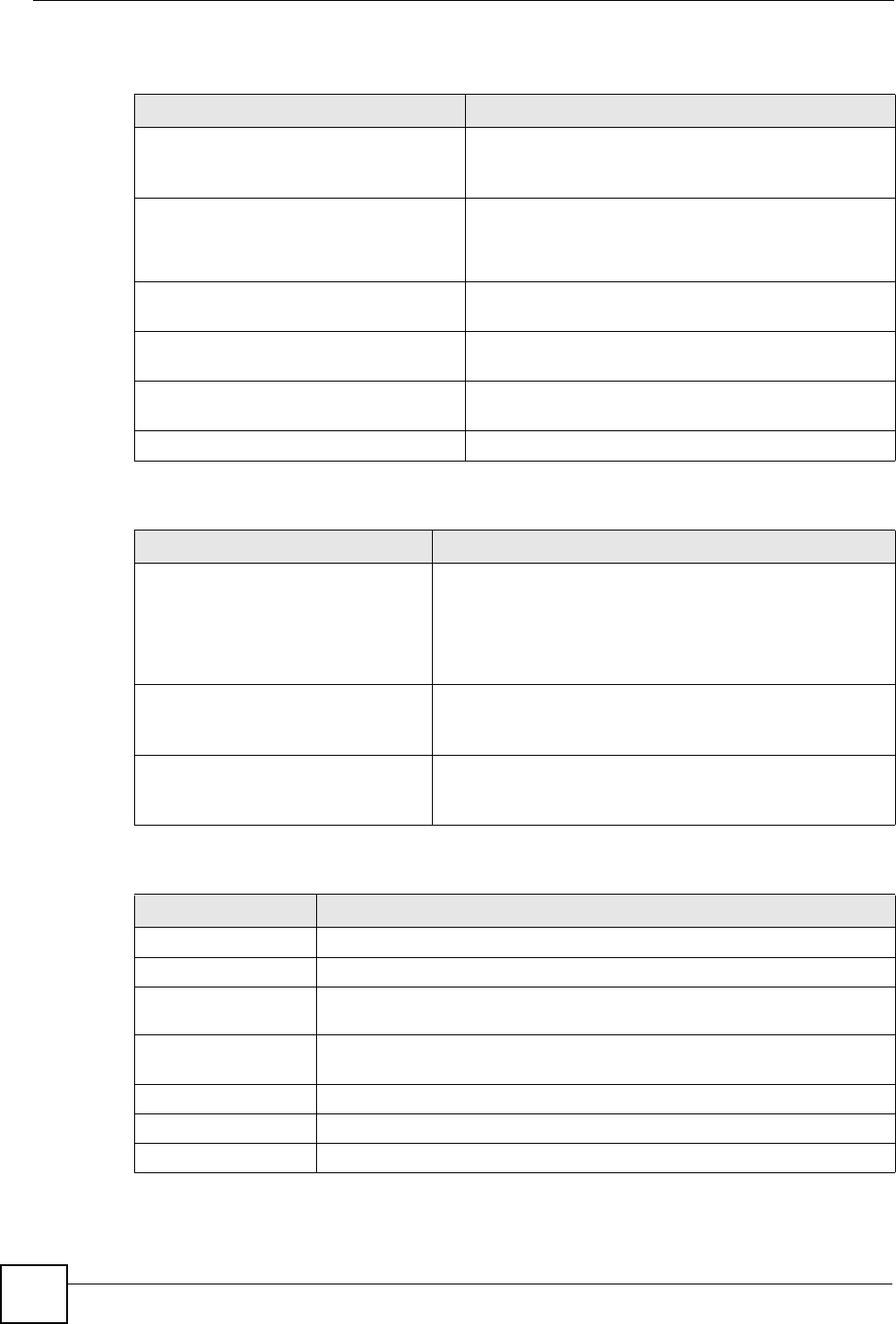
Table 94 System Maintenance Logs
LOG MESSAGE DESCRIPTION
Time calibration is
successful
The router has adjusted its time based on information from
the time server.
Time calibration failed The router failed to get information from the time server.
WAN interface gets IP:%s A WAN interface got a new IP address from the DHCP,
PPPoE, PPTP or dial-up server.
DHCP client IP expired A DHCP client's IP address has expired.
DHCP server assigns%s The DHCP server assigned an IP address to a client.
Successful WEB login Someone has logged on to the router's web configurator
interface.
WEB login failed Someone has failed to log on to the router's web configurator
interface.
Successful TELNET login Someone has logged on to the router via telnet.
TELNET login failed Someone has failed to log on to the router via telnet.
Successful FTP login Someone has logged on to the router via ftp.
FTP login failed Someone has failed to log on to the router via ftp.
NAT Session Table is Full! The maximum number of NAT session table entries has been
exceeded and the table is full.
Chapter 18 Logs
P-660HW-Dx v2 User’s Guide
238
Starting Connectivity
Monitor
Starting Connectivity Monitor.
Time initialized by Daytime
Server
The router got the time and date from the Daytime server.
Time initialized by Time
server
The router got the time and date from the time server.
Time initialized by NTP
server
The router got the time and date from the NTP server.
Connect to Daytime server
fail
The router was not able to connect to the Daytime server.
Connect to Time server fail The router was not able to connect to the Time server.
Connect to NTP server fail The router was not able to connect to the NTP server.
Too large ICMP packet has
been dropped
The router dropped an ICMP packet that was too large.
Configuration Change: PC =
0x%x, Task ID = 0x%x
The router is saving configuration changes.
Successful SSH login Someone has logged on to the router’s SSH server.
SSH login failed Someone has failed to log on to the router’s SSH server.
Successful HTTPS login Someone has logged on to the router's web configurator
interface using HTTPS protocol.
HTTPS login failed Someone has failed to log on to the router's web configurator
interface using HTTPS protocol.
Table 95 System Error Logs
LOG MESSAGE DESCRIPTION
%s exceeds the max.
number of session per
host!
This attempt to create a NAT session exceeds the maximum
number of NAT session table entries allowed to be created per
host.
setNetBIOSFilter: calloc
error
The router failed to allocate memory for the NetBIOS filter
settings.
readNetBIOSFilter: calloc
error
The router failed to allocate memory for the NetBIOS filter
settings.
WAN connection is down. A WAN connection is down. You cannot access the network
through this interface.
Table 96 Access Control Logs
LOG MESSAGE DESCRIPTION
Firewall default policy: [TCP |
UDP | IGMP | ESP | GRE | OSPF]
<Packet Direction>
Attempted TCP/UDP/IGMP/ESP/GRE/OSPF access
matched the default policy and was blocked or forwarded
according to the default policy’s setting.
Firewall rule [NOT] match:[TCP |
UDP | IGMP | ESP | GRE | OSPF]
<Packet Direction>, <rule:%d>
Attempted TCP/UDP/IGMP/ESP/GRE/OSPF access
matched (or did not match) a configured firewall rule
(denoted by its number) and was blocked or forwarded
according to the rule.
Table 94 System Maintenance Logs (continued)
LOG MESSAGE DESCRIPTION

Chapter 18 Logs
P-660HW-Dx v2 User’s Guide 239
Triangle route packet forwarded:
[TCP | UDP | IGMP | ESP | GRE |
OSPF]
The firewall allowed a triangle route session to pass
through.
Packet without a NAT table entry
blocked: [TCP | UDP | IGMP | ESP
| GRE | OSPF]
The router blocked a packet that didn't have a
corresponding NAT table entry.
Router sent blocked web site
message: TCP
The router sent a message to notify a user that the router
blocked access to a web site that the user requested.
Table 97 TCP Reset Logs
LOG MESSAGE DESCRIPTION
Under SYN flood attack,
sent TCP RST
The router sent a TCP reset packet when a host was under a SYN
flood attack (the TCP incomplete count is per destination host.)
Exceed TCP MAX
incomplete, sent TCP RST
The router sent a TCP reset packet when the number of TCP
incomplete connections exceeded the user configured threshold.
(the TCP incomplete count is per destination host.) Note: Refer to
TCP Maximum Incomplete in the Firewall Attack Alerts screen.
Peer TCP state out of
order, sent TCP RST
The router sent a TCP reset packet when a TCP connection state
was out of order.Note: The firewall refers to RFC793 Figure 6 to
check the TCP state.
Firewall session time
out, sent TCP RST
The router sent a TCP reset packet when a dynamic firewall
session timed out.
The default timeout values are as follows:
ICMP idle timeout: 3 minutes
UDP idle timeout: 3 minutes
TCP connection (three way handshaking) timeout: 270 seconds
TCP FIN-wait timeout: 2 MSL (Maximum Segment Lifetime set in
the TCP header).
TCP idle (established) timeout (s): 150 minutes
TCP reset timeout: 10 seconds
Exceed MAX incomplete,
sent TCP RST
The router sent a TCP reset packet when the number of
incomplete connections (TCP and UDP) exceeded the user-
configured threshold. (Incomplete count is for all TCP and UDP
connections through the firewall.)Note: When the number of
incomplete connections (TCP + UDP) > “Maximum Incomplete
High”, the router sends TCP RST packets for TCP connections
and destroys TOS (firewall dynamic sessions) until incomplete
connections < “Maximum Incomplete Low”.
Access block, sent TCP
RST
The router sends a TCP RST packet and generates this log if you
turn on the firewall TCP reset mechanism (via CI command: "sys
firewall tcprst").
Table 98 Packet Filter Logs
LOG MESSAGE DESCRIPTION
[TCP | UDP | ICMP | IGMP |
Generic] packet filter
matched (set:%d, rule:%d)
Attempted access matched a configured filter rule (denoted
by its set and rule number) and was blocked or forwarded
according to the rule.
Table 96 Access Control Logs (continued)
LOG MESSAGE DESCRIPTION
Chapter 18 Logs
P-660HW-Dx v2 User’s Guide
240
Table 99 ICMP Logs
LOG MESSAGE DESCRIPTION
Firewall default policy: ICMP
<Packet Direction>, <type:%d>,
<code:%d>
ICMP access matched the default policy and was
blocked or forwarded according to the user's setting. For
type and code details, see Table 110 on page 248.
Firewall rule [NOT] match: ICMP
<Packet Direction>, <rule:%d>,
<type:%d>, <code:%d>
ICMP access matched (or didn’t match) a firewall rule
(denoted by its number) and was blocked or forwarded
according to the rule. For type and code details, see
Table 110 on page 248.
Triangle route packet forwarded:
ICMP
The firewall allowed a triangle route session to pass
through.
Packet without a NAT table entry
blocked: ICMP
The router blocked a packet that didn’t have a
corresponding NAT table entry.
Unsupported/out-of-order ICMP:
ICMP
The firewall does not support this kind of ICMP packets
or the ICMP packets are out of order.
Router reply ICMP packet: ICMP The router sent an ICMP reply packet to the sender.
Table 100 CDR Logs
LOG MESSAGE DESCRIPTION
board%d line%d channel%d,
call%d,%s C01 Outgoing Call
dev=%x ch=%x%s
The router received the setup requirements for a call. “call” is
the reference (count) number of the call. “dev” is the device
type (3 is for dial-up, 6 is for PPPoE, 10 is for PPTP).
"channel" or “ch” is the call channel ID.For example,"board 0
line 0 channel 0, call 3, C01 Outgoing Call dev=6 ch=0
"Means the router has dialed to the PPPoE server 3 times.
board%d line%d channel%d,
call%d,%s C02 OutCall
Connected%d%s
The PPPoE, PPTP or dial-up call is connected.
board%d line%d channel%d,
call%d,%s C02 Call
Terminated
The PPPoE, PPTP or dial-up call was disconnected.
Table 101 PPP Logs
LOG MESSAGE DESCRIPTION
ppp:LCP Starting The PPP connection’s Link Control Protocol stage has started.
ppp:LCP Opening The PPP connection’s Link Control Protocol stage is opening.
ppp:CHAP Opening The PPP connection’s Challenge Handshake Authentication Protocol stage is
opening.
ppp:IPCP
Starting
The PPP connection’s Internet Protocol Control Protocol stage is starting.
ppp:IPCP Opening The PPP connection’s Internet Protocol Control Protocol stage is opening.
ppp:LCP Closing The PPP connection’s Link Control Protocol stage is closing.
ppp:IPCP Closing The PPP connection’s Internet Protocol Control Protocol stage is closing.

Chapter 18 Logs
P-660HW-Dx v2 User’s Guide 241
Table 102 UPnP Logs
LOG MESSAGE DESCRIPTION
UPnP pass through Firewall UPnP packets can pass through the firewall.
Table 103 Content Filtering Logs
LOG MESSAGE DESCRIPTION
%s: Keyword blocking The content of a requested web page matched a user defined
keyword.
%s: Not in trusted web
list
The web site is not in a trusted domain, and the router blocks all traffic
except trusted domain sites.
%s: Forbidden Web site The web site is in the forbidden web site list.
%s: Contains ActiveX The web site contains ActiveX.
%s: Contains Java
applet
The web site contains a Java applet.
%s: Contains cookie The web site contains a cookie.
%s: Proxy mode
detected
The router detected proxy mode in the packet.
%s The content filter server responded that the web site is in the blocked
category list, but it did not return the category type.
%s:%s The content filter server responded that the web site is in the blocked
category list, and returned the category type.
%s(cache hit) The system detected that the web site is in the blocked list from the
local cache, but does not know the category type.
%s:%s(cache hit) The system detected that the web site is in blocked list from the local
cache, and knows the category type.
%s: Trusted Web site The web site is in a trusted domain.
%s When the content filter is not on according to the time schedule or you
didn't select the "Block Matched Web Site” check box, the system
forwards the web content.
Waiting content filter
server timeout
The external content filtering server did not respond within the timeout
period.
DNS resolving failed The ZyXEL Device cannot get the IP address of the external content
filtering via DNS query.
Creating socket failed The ZyXEL Device cannot issue a query because TCP/IP socket
creation failed, port:port number.
Connecting to content
filter server fail
The connection to the external content filtering server failed.
License key is invalid The external content filtering license key is invalid.

Chapter 18 Logs
P-660HW-Dx v2 User’s Guide
242
Table 104 Attack Logs
LOG MESSAGE DESCRIPTION
attack [TCP | UDP | IGMP
| ESP | GRE | OSPF]
The firewall detected a TCP/UDP/IGMP/ESP/GRE/OSPF attack.
attack ICMP (type:%d,
code:%d)
The firewall detected an ICMP attack. For type and code details,
see Table 110 on page 248.
land [TCP | UDP | IGMP |
ESP | GRE | OSPF]
The firewall detected a TCP/UDP/IGMP/ESP/GRE/OSPF land
attack.
land ICMP (type:%d,
code:%d)
The firewall detected an ICMP land attack. For type and code
details, see Table 110 on page 248.
ip spoofing - WAN [TCP |
UDP | IGMP | ESP | GRE |
OSPF]
The firewall detected an IP spoofing attack on the WAN port.
ip spoofing - WAN ICMP
(type:%d, code:%d)
The firewall detected an ICMP IP spoofing attack on the WAN
port. For type and code details, see Table 110 on page 248.
icmp echo: ICMP (type:%d,
code:%d)
The firewall detected an ICMP echo attack. For type and code
details, see Table 110 on page 248.
syn flood TCP The firewall detected a TCP syn flood attack.
ports scan TCP The firewall detected a TCP port scan attack.
teardrop TCP The firewall detected a TCP teardrop attack.
teardrop UDP The firewall detected an UDP teardrop attack.
teardrop ICMP (type:%d,
code:%d)
The firewall detected an ICMP teardrop attack. For type and code
details, see Table 110 on page 248.
illegal command TCP The firewall detected a TCP illegal command attack.
NetBIOS TCP The firewall detected a TCP NetBIOS attack.
ip spoofing - no routing
entry [TCP | UDP | IGMP |
ESP | GRE | OSPF]
The firewall classified a packet with no source routing entry as an
IP spoofing attack.
ip spoofing - no routing
entry ICMP (type:%d,
code:%d)
The firewall classified an ICMP packet with no source routing
entry as an IP spoofing attack.
vulnerability ICMP
(type:%d, code:%d)
The firewall detected an ICMP vulnerability attack. For type and
code details, see Table 110 on page 248.
traceroute ICMP (type:%d,
code:%d)
The firewall detected an ICMP traceroute attack. For type and
code details, see Table 110 on page 248.
Table 105 IPSec Logs
LOG MESSAGE DESCRIPTION
Discard REPLAY packet The router received and discarded a packet with an incorrect
sequence number.
Inbound packet
authentication failed
The router received a packet that has been altered. A third party
may have altered or tampered with the packet.
Receive IPSec packet,
but no corresponding
tunnel exists
The router dropped an inbound packet for which SPI could not find a
corresponding phase 2 SA.

Chapter 18 Logs
P-660HW-Dx v2 User’s Guide 243
Rule <%d> idle time
out, disconnect
The router dropped a connection that had outbound traffic and no
inbound traffic for a certain time period. You can use the "ipsec timer
chk_conn" CI command to set the time period. The default value is 2
minutes.
WAN IP changed to <IP> The router dropped all connections with the “MyIP” configured as
“0.0.0.0” when the WAN IP address changed.
Table 106 IKE Logs
LOG MESSAGE DESCRIPTION
Active connection allowed
exceeded
The IKE process for a new connection failed because the limit
of simultaneous phase 2 SAs has been reached.
Start Phase 2: Quick Mode Phase 2 Quick Mode has started.
Verifying Remote ID failed: The connection failed during IKE phase 2 because the router
and the peer’s Local/Remote Addresses don’t match.
Verifying Local ID failed: The connection failed during IKE phase 2 because the router
and the peer’s Local/Remote Addresses don’t match.
IKE Packet Retransmit The router retransmitted the last packet sent because there
was no response from the peer.
Failed to send IKE Packet An Ethernet error stopped the router from sending IKE
packets.
Too many errors! Deleting SA An SA was deleted because there were too many errors.
Phase 1 IKE SA process done The phase 1 IKE SA process has been completed.
Duplicate requests with the
same cookie
The router received multiple requests from the same peer
while still processing the first IKE packet from the peer.
IKE Negotiation is in
process
The router has already started negotiating with the peer for
the connection, but the IKE process has not finished yet.
No proposal chosen Phase 1 or phase 2 parameters don’t match. Please check all
protocols / settings. Ex. One device being configured for
3DES and the other being configured for DES causes the
connection to fail.
Local / remote IPs of
incoming request conflict
with rule <%d>
The security gateway is set to “0.0.0.0” and the router used
the peer’s “Local Address” as the router’s “Remote Address”.
This information conflicted with static rule #d; thus the
connection is not allowed.
Cannot resolve Secure
Gateway Addr for rule <%d>
The router couldn’t resolve the IP address from the domain
name that was used for the secure gateway address.
Peer ID: <peer id> <My remote
type> -<My local type>
The displayed ID information did not match between the two
ends of the connection.
vs. My Remote <My remote> -
<My remote>
The displayed ID information did not match between the two
ends of the connection.
vs. My Local <My local>-<My
local>
The displayed ID information did not match between the two
ends of the connection.
Send <packet> A packet was sent.
Table 105 IPSec Logs (continued)
LOG MESSAGE DESCRIPTION

Chapter 18 Logs
P-660HW-Dx v2 User’s Guide
244
Recv <packet> IKE uses ISAKMP to transmit data. Each ISAKMP packet
contains many different types of payloads. All of them show in
the LOG. Refer to RFC2408 – ISAKMP for a list of all
ISAKMP payload types.
Recv <Main or Aggressive>
Mode request from <IP>
The router received an IKE negotiation request from the peer
address specified.
Send <Main or Aggressive>
Mode request to <IP>
The router started negotiation with the peer.
Invalid IP <Peer local> /
<Peer local>
The peer’s “Local IP Address” is invalid.
Remote IP <Remote IP> /
<Remote IP> conflicts
The security gateway is set to “0.0.0.0” and the router used
the peer’s “Local Address” as the router’s “Remote Address”.
This information conflicted with static rule #d; thus the
connection is not allowed.
Phase 1 ID type mismatch This router’s "Peer ID Type" is different from the peer IPSec
router's "Local ID Type".
Phase 1 ID content mismatch This router’s "Peer ID Content" is different from the peer
IPSec router's "Local ID Content".
No known phase 1 ID type
found
The router could not find a known phase 1 ID in the
connection attempt.
ID type mismatch. Local /
Peer: <Local ID type/Peer ID
type>
The phase 1 ID types do not match.
ID content mismatch The phase 1 ID contents do not match.
Configured Peer ID Content:
<Configured Peer ID Content>
The phase 1 ID contents do not match and the configured
"Peer ID Content" is displayed.
Incoming ID Content:
<Incoming Peer ID Content>
The phase 1 ID contents do not match and the incoming
packet's ID content is displayed.
Unsupported local ID Type:
<%d>
The phase 1 ID type is not supported by the router.
Build Phase 1 ID The router has started to build the phase 1 ID.
Adjust TCP MSS to%d The router automatically changed the TCP Maximum
Segment Size value after establishing a tunnel.
Rule <%d> input idle time
out, disconnect
The tunnel for the listed rule was dropped because there was
no inbound traffic within the idle timeout period.
XAUTH succeed! Username:
<Username>
The router used extended authentication to authenticate the
listed username.
XAUTH fail! Username:
<Username>
The router was not able to use extended authentication to
authenticate the listed username.
Rule[%d] Phase 1 negotiation
mode mismatch
The listed rule’s IKE phase 1 negotiation mode did not match
between the router and the peer.
Rule [%d] Phase 1 encryption
algorithm mismatch
The listed rule’s IKE phase 1 encryption algorithm did not
match between the router and the peer.
Rule [%d] Phase 1
authentication algorithm
mismatch
The listed rule’s IKE phase 1 authentication algorithm did not
match between the router and the peer.
Table 106 IKE Logs (continued)
LOG MESSAGE DESCRIPTION

Chapter 18 Logs
P-660HW-Dx v2 User’s Guide 245
Rule [%d] Phase 1
authentication method
mismatch
The listed rule’s IKE phase 1 authentication method did not
match between the router and the peer.
Rule [%d] Phase 1 key group
mismatch
The listed rule’s IKE phase 1 key group did not match
between the router and the peer.
Rule [%d] Phase 2 protocol
mismatch
The listed rule’s IKE phase 2 protocol did not match between
the router and the peer.
Rule [%d] Phase 2 encryption
algorithm mismatch
The listed rule’s IKE phase 2 encryption algorithm did not
match between the router and the peer.
Rule [%d] Phase 2
authentication algorithm
mismatch
The listed rule’s IKE phase 2 authentication algorithm did not
match between the router and the peer.
Rule [%d] Phase 2
encapsulation mismatch
The listed rule’s IKE phase 2 encapsulation did not match
between the router and the peer.
Rule [%d]> Phase 2 pfs
mismatch
The listed rule’s IKE phase 2 perfect forward secret (pfs)
setting did not match between the router and the peer.
Rule [%d] Phase 1 ID mismatch The listed rule’s IKE phase 1 ID did not match between the
router and the peer.
Rule [%d] Phase 1 hash
mismatch
The listed rule’s IKE phase 1 hash did not match between the
router and the peer.
Rule [%d] Phase 1 preshared
key mismatch
The listed rule’s IKE phase 1 pre-shared key did not match
between the router and the peer.
Rule [%d] Tunnel built
successfully
The listed rule’s IPSec tunnel has been built successfully.
Rule [%d] Peer's public key
not found
The listed rule’s IKE phase 1 peer’s public key was not found.
Rule [%d] Verify peer's
signature failed
The listed rule’s IKE phase 1verification of the peer’s
signature failed.
Rule [%d] Sending IKE
request
IKE sent an IKE request for the listed rule.
Rule [%d] Receiving IKE
request
IKE received an IKE request for the listed rule.
Swap rule to rule [%d] The router changed to using the listed rule.
Rule [%d] Phase 1 key length
mismatch
The listed rule’s IKE phase 1 key length (with the AES
encryption algorithm) did not match between the router and
the peer.
Rule [%d] phase 1 mismatch The listed rule’s IKE phase 1 did not match between the
router and the peer.
Rule [%d] phase 2 mismatch The listed rule’s IKE phase 2 did not match between the
router and the peer.
Rule [%d] Phase 2 key length
mismatch
The listed rule’s IKE phase 2 key lengths (with the AES
encryption algorithm) did not match between the router and
the peer.
Table 106 IKE Logs (continued)
LOG MESSAGE DESCRIPTION

Chapter 18 Logs
P-660HW-Dx v2 User’s Guide
246
Table 107 PKI Logs
LOG MESSAGE DESCRIPTION
Enrollment successful The SCEP online certificate enrollment was successful. The
Destination field records the certification authority server IP address
and port.
Enrollment failed The SCEP online certificate enrollment failed. The Destination field
records the certification authority server’s IP address and port.
Failed to resolve
<SCEP CA server url>
The SCEP online certificate enrollment failed because the certification
authority server’s address cannot be resolved.
Enrollment successful The CMP online certificate enrollment was successful. The Destination
field records the certification authority server’s IP address and port.
Enrollment failed The CMP online certificate enrollment failed. The Destination field
records the certification authority server’s IP address and port.
Failed to resolve <CMP
CA server url>
The CMP online certificate enrollment failed because the certification
authority server’s IP address cannot be resolved.
Rcvd ca cert: <subject
name>
The router received a certification authority certificate, with subject
name as recorded, from the LDAP server whose IP address and port
are recorded in the Source field.
Rcvd user cert:
<subject name>
The router received a user certificate, with subject name as recorded,
from the LDAP server whose IP address and port are recorded in the
Source field.
Rcvd CRL <size>:
<issuer name>
The router received a CRL (Certificate Revocation List), with size and
issuer name as recorded, from the LDAP server whose IP address and
port are recorded in the Source field.
Rcvd ARL <size>:
<issuer name>
The router received an ARL (Authority Revocation List), with size and
issuer name as recorded, from the LDAP server whose address and
port are recorded in the Source field.
Failed to decode the
received ca cert
The router received a corrupted certification authority certificate from
the LDAP server whose address and port are recorded in the Source
field.
Failed to decode the
received user cert
The router received a corrupted user certificate from the LDAP server
whose address and port are recorded in the Source field.
Failed to decode the
received CRL
The router received a corrupted CRL (Certificate Revocation List) from
the LDAP server whose address and port are recorded in the Source
field.
Failed to decode the
received ARL
The router received a corrupted ARL (Authority Revocation List) from
the LDAP server whose address and port are recorded in the Source
field.
Rcvd data <size> too
large! Max size
allowed: <max size>
The router received directory data that was too large (the size is listed)
from the LDAP server whose address and port are recorded in the
Source field. The maximum size of directory data that the router allows
is also recorded.
Cert trusted: <subject
name>
The router has verified the path of the certificate with the listed subject
name.
Due to <reason codes>,
cert not trusted:
<subject name>
Due to the reasons listed, the certificate with the listed subject name
has not passed the path verification. The recorded reason codes are
only approximate reasons for not trusting the certificate. Please see
Table 108 on page 247 for the corresponding descriptions of the
codes.

Chapter 18 Logs
P-660HW-Dx v2 User’s Guide 247
Table 108 Certificate Path Verification Failure Reason Codes
CODE DESCRIPTION
1Algorithm mismatch between the certificate and the search constraints.
2Key usage mismatch between the certificate and the search constraints.
3Certificate was not valid in the time interval.
4(Not used)
5Certificate is not valid.
6Certificate signature was not verified correctly.
7Certificate was revoked by a CRL.
8Certificate was not added to the cache.
9Certificate decoding failed.
10 Certificate was not found (anywhere).
11 Certificate chain looped (did not find trusted root).
12 Certificate contains critical extension that was not handled.
13 Certificate issuer was not valid (CA specific information missing).
14 (Not used)
15 CRL is too old.
16 CRL is not valid.
17 CRL signature was not verified correctly.
18 CRL was not found (anywhere).
19 CRL was not added to the cache.
20 CRL decoding failed.
21 CRL is not currently valid, but in the future.
22 CRL contains duplicate serial numbers.
23 Time interval is not continuous.
24 Time information not available.
25 Database method failed due to timeout.
26 Database method failed.
27 Path was not verified.
28 Maximum path length reached.
Table 109 ACL Setting Notes
PACKET DIRECTION DIRECTION DESCRIPTION
(L to W) LAN to WAN ACL set for packets traveling from the LAN to the WAN.
(W to L) WAN to LAN ACL set for packets traveling from the WAN to the LAN.
(L to L) LAN to LAN/
ZyXEL Device
ACL set for packets traveling from the LAN to the LAN or
the ZyXEL Device.
(W to W) WAN to WAN/
ZyXEL Device
ACL set for packets traveling from the WAN to the WAN
or the ZyXEL Device.

Chapter 18 Logs
P-660HW-Dx v2 User’s Guide
248
Table 110 ICMP Notes
TYPE CODE DESCRIPTION
0Echo Reply
0Echo reply message
3Destination Unreachable
0Net unreachable
1Host unreachable
2Protocol unreachable
3Port unreachable
4A packet that needed fragmentation was dropped because it was set to Don't
Fragment (DF)
5Source route failed
4Source Quench
0A gateway may discard internet datagrams if it does not have the buffer space
needed to queue the datagrams for output to the next network on the route to
the destination network.
5Redirect
0Redirect datagrams for the Network
1Redirect datagrams for the Host
2Redirect datagrams for the Type of Service and Network
3Redirect datagrams for the Type of Service and Host
8Echo
0Echo message
11 Time Exceeded
0Time to live exceeded in transit
1Fragment reassembly time exceeded
12 Parameter Problem
0Pointer indicates the error
13 Timestamp
0Timestamp request message
14 Timestamp Reply
0Timestamp reply message
15 Information Request
0Information request message
16 Information Reply
0Information reply message
Chapter 18 Logs
P-660HW-Dx v2 User’s Guide 249
The following table shows RFC-2408 ISAKMP payload types that the log displays. Please
refer to the RFC for detailed information on each type.
Table 111 Syslog Logs
LOG MESSAGE DESCRIPTION
<Facility*8 + Severity>Mon dd
hr:mm:ss hostname
src="<srcIP:srcPort>"
dst="<dstIP:dstPort>"
msg="<msg>" note="<note>"
devID="<mac address last three
numbers>" cat="<category>
"This message is sent by the system ("RAS" displays as
the system name if you haven’t configured one) when the
router generates a syslog. The facility is defined in the web
MAIN MENU->LOGS->Log Settings page. The severity is
the log’s syslog class. The definition of messages and
notes are defined in the various log charts throughout this
appendix. The “devID” is the last three characters of the
MAC address of the router’s LAN port. The “cat” is the
same as the category in the router’s logs.
Table 112 RFC-2408 ISAKMP Payload Types
LOG DISPLAY PAYLOAD TYPE
SA Security Association
PROP Proposal
TRANS Transform
KE Key Exchange
ID Identification
CER Certificate
CER_REQ Certificate Request
HASH Hash
SIG Signature
NONCE Nonce
NOTFY Notification
DEL Delete
VID Vendor ID

Chapter 18 Logs
P-660HW-Dx v2 User’s Guide
250
P-660HW-Dx v2 User’s Guide 251
CHAPTER 19
Tools
This chapter describes how to upload new firmware, manage configuration and restart your
ZyXEL Device.
19.1 Firmware Upgrade
Find firmware at www.zyxel.com in a file that (usually) uses the system model name with a
.bin extension, for example, "ZyXEL Device.bin". The upload process uses HTTP (Hypertext
Transfer Protocol) and may take up to two minutes. After a successful upload, the system will
reboot.
Only use firmware for your device’s specific model. Refer to the label on the bottom of your
device.
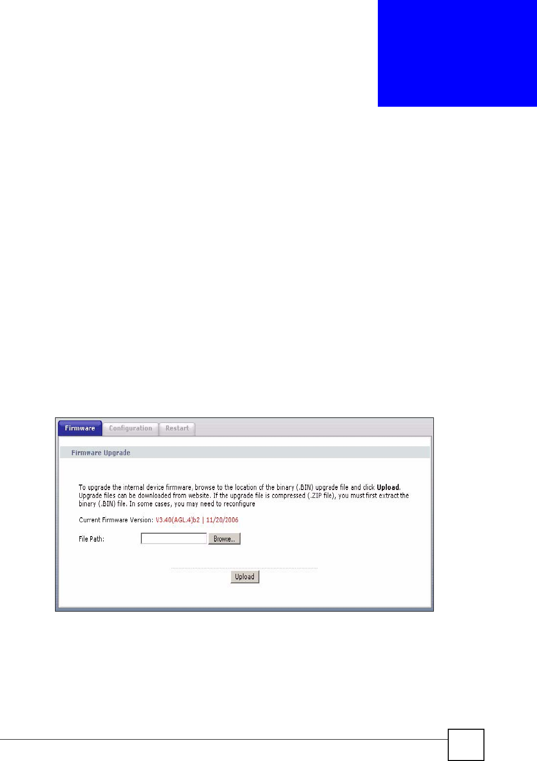
Click Maintenance > Tools to open the Firmware screen. Follow the instructions in this
screen to upload firmware to your ZyXEL Device.
Figure 143 Firmware
Chapter 19 Tools
P-660HW-Dx v2 User’s Guide
252
The following table describes the labels in this screen.
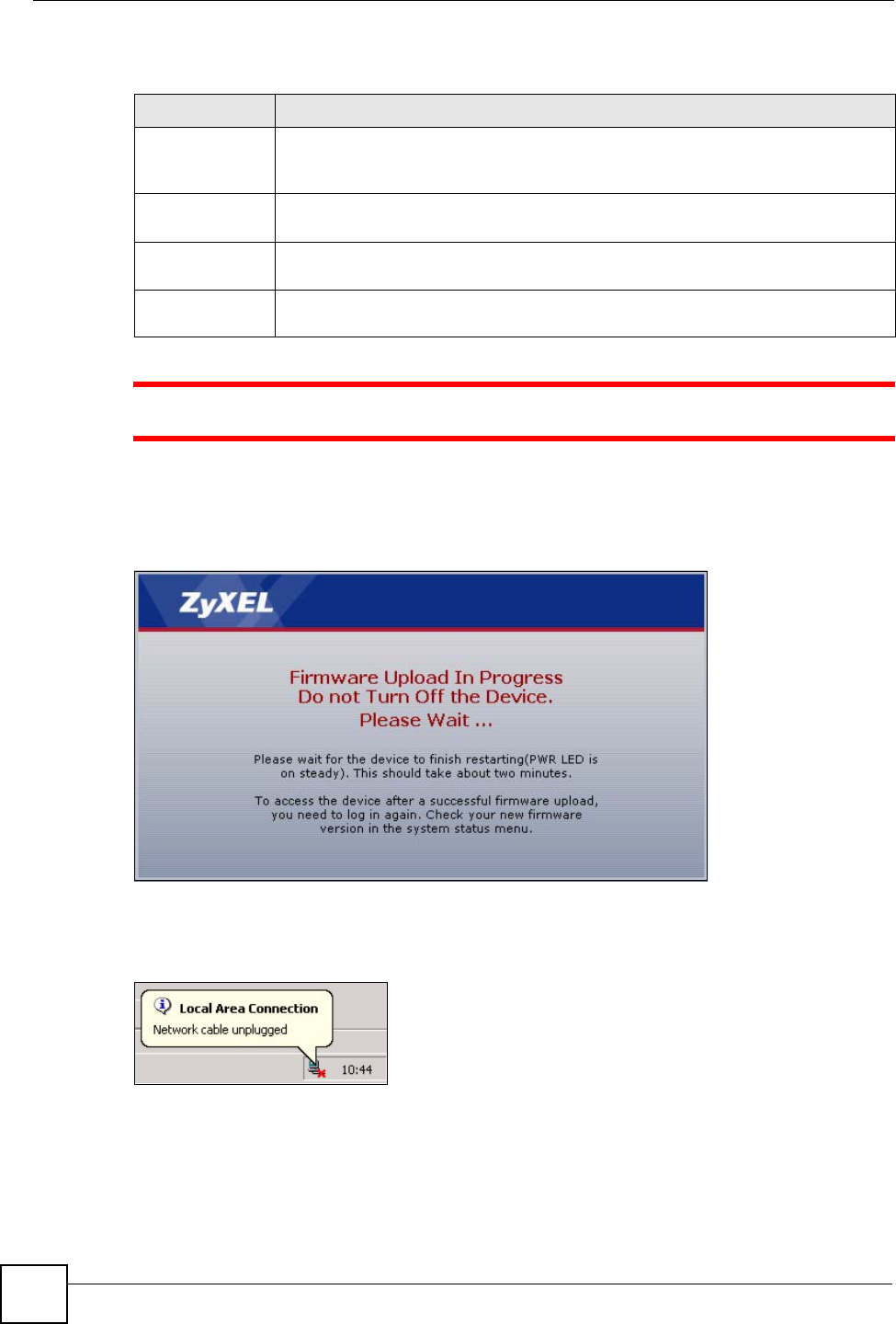
1Do NOT turn off the ZyXEL Device while firmware upload is in progress!
After you see the Firmware Upload in Progress screen, wait two minutes before logging into
the ZyXEL Device again.
Figure 144 Firmware Upload In Progress
The ZyXEL Device automatically restarts in this time causing a temporary network
disconnect. In some operating systems, you may see the following icon on your desktop.
Figure 145 Network Temporarily Disconnected
After two minutes, log in again and check your new firmware version in the Status screen.
If the upload was not successful, the following screen will appear. Click Return to go back to
the Firmware screen.
Table 113 Firmware Upgrade
LABEL DESCRIPTION
Current
Firmware
Version
This is the present Firmware version and the date created.
File Path Type in the location of the file you want to upload in this field or click Browse ... to
find it.
Browse... Click Browse... to find the .bin file you want to upload. Remember that you must
decompress compressed (.zip) files before you can upload them.
Upload Click Upload to begin the upload process. This process may take up to two
minutes.
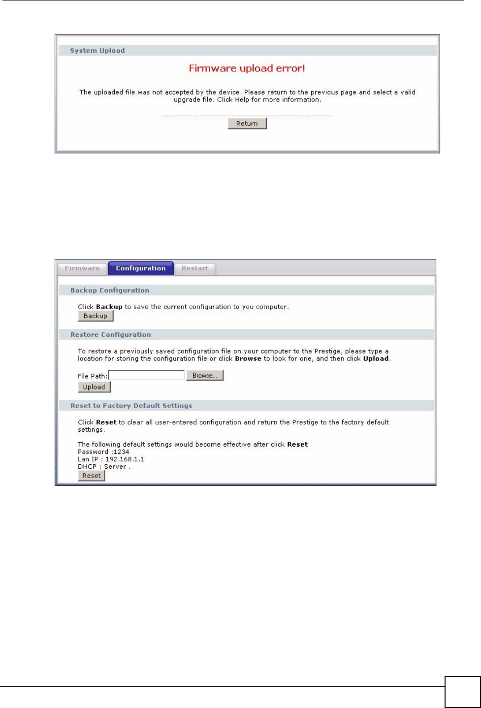
Chapter 19 Tools
P-660HW-Dx v2 User’s Guide 253
Figure 146 Error Message
19.2 Configuration Screen
Click Maintenance > Tools > Configuration. Information related to factory defaults, backup
configuration, and restoring configuration appears as shown next.
Figure 147 Configuration
19.2.1 Backup Configuration
Backup configuration allows you to back up (save) the ZyXEL Device’s current configuration
to a file on your computer. Once your ZyXEL Device is configured and functioning properly,
it is highly recommended that you back up your configuration file before making
configuration changes. The backup configuration file will be useful in case you need to return
to your previous settings.
Click Backup to save the ZyXEL Device’s current configuration to your computer
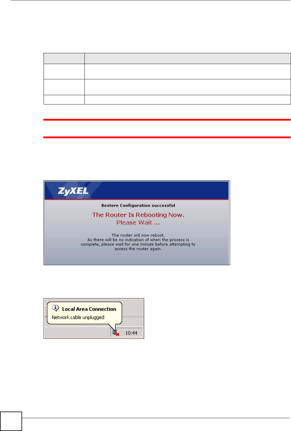
Chapter 19 Tools
P-660HW-Dx v2 User’s Guide
254
19.2.2 Restore Configuration
Restore configuration allows you to upload a new or previously saved configuration file from
your computer to your ZyXEL Device.
1Do not turn off the ZyXEL Device while configuration file upload is in progress
After you see a “Restore Configuration successful” screen, you must then wait one minute
before logging into the ZyXEL Device again.
Figure 148 Configuration Restore Successful
The ZyXEL Device automatically restarts in this time causing a temporary network
disconnect. In some operating systems, you may see the following icon on your desktop.
Figure 149 Temporarily Disconnected
If you uploaded the default configuration file you may need to change the IP address of your
computer to be in the same subnet as that of the default ZyXEL Device IP address
(192.168.1.1). See the appendix for details on how to set up your computer’s IP address.
If the upload was not successful, the following screen will appear. Click Return to go back to
the Configuration screen.
Table 114 Maintenance Restore Configuration
LABEL DESCRIPTION
File Path Type in the location of the file you want to upload in this field or click Browse... to find
it.
Browse... Click Browse... to find the file you want to upload. Remember that you must
decompress compressed (.ZIP) files before you can upload them.
Upload Click Upload to begin the upload process.
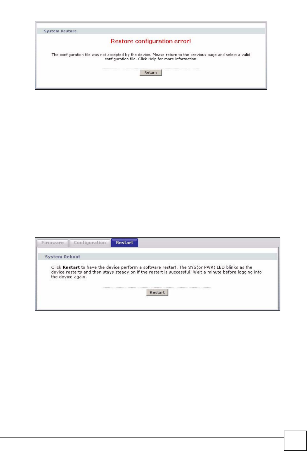
Chapter 19 Tools
P-660HW-Dx v2 User’s Guide 255
Figure 150 Configuration Restore Error
19.2.3 Back to Factory Defaults
Pressing the RESET button in this section clears all user-entered configuration information
and returns the ZyXEL Device to its factory defaults.
You can also press the RESET button on the rear panel to reset the factory defaults of your
ZyXEL Device. Refer to the chapter about introducing the web configurator for more
information on the RESET button.
19.3 Restart
System restart allows you to reboot the ZyXEL Device without turning the power off.
Click Maintenance > Tools > Restart. Click Restart to have the ZyXEL Device reboot. This
does not affect the ZyXEL Device's configuration.
Figure 151 Restart Screen

Chapter 19 Tools
P-660HW-Dx v2 User’s Guide
256
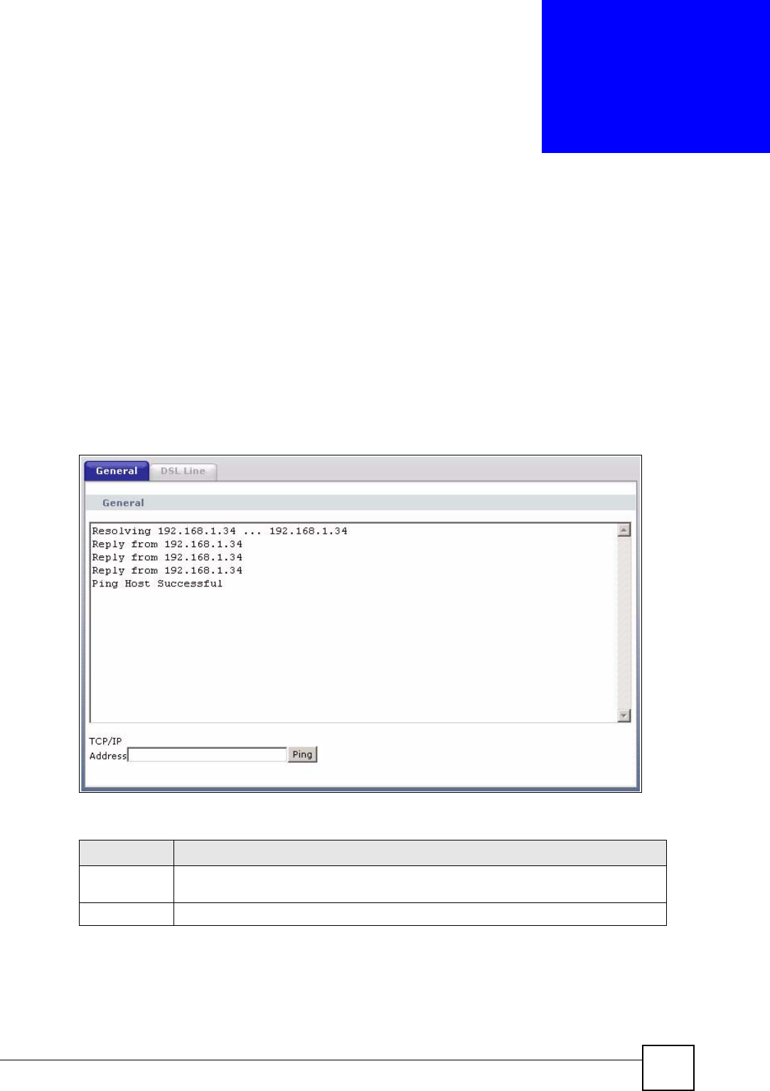
P-660HW-Dx v2 User’s Guide 257
CHAPTER 20
Diagnostic
These read-only screens display information to help you identify problems with the ZyXEL
Device.
20.1 General Diagnostic
Click Maintenance > Diagnostic to open the screen shown next.
Figure 152 Diagnostic: General
The following table describes the fields in this screen.
20.2 DSL Line Diagnostic
Click Maintenance > Diagnostic > DSL Line to open the screen shown next.
Table 115 Diagnostic: General
LABEL DESCRIPTION
TCP/IP
Address
Type the IP address of a computer that you want to ping in order to test a connection.
Ping Click this button to ping the IP address that you entered.
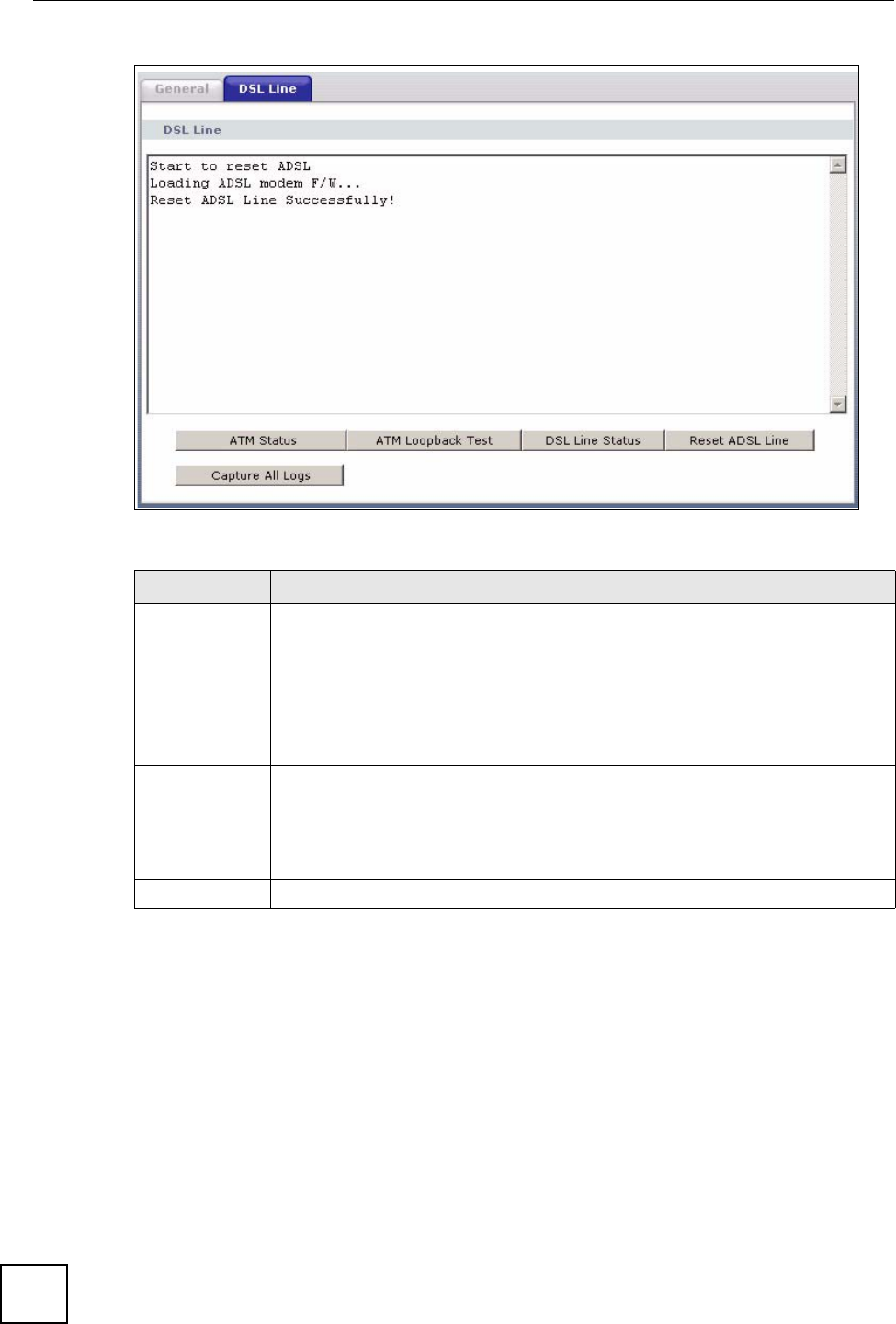
Chapter 20 Diagnostic
P-660HW-Dx v2 User’s Guide
258
Figure 153 Diagnostic: DSL Line
The following table describes the fields in this screen.
Table 116 Diagnostic: DSL Line
LABEL DESCRIPTION
ATM Status Click this button to view ATM status.
ATM Loopback
Te s t
Click this button to start the ATM loopback test. Make sure you have configured at
least one PVC with proper VPIs/VCIs before you begin this test. The ZyXEL Device
sends an OAM F5 packet to the DSLAM/ATM switch and then returns it (loops it
back) to the ZyXEL Device. The ATM loopback test is useful for troubleshooting
problems with the DSLAM and ATM network.
DSL Line Status Click this button to view the DSL port’s line operating values and line bit allocation.
Reset ADSL
Line
Click this button to reinitialize the ADSL line. The large text box above then displays
the progress and results of this operation, for example:
"Start to reset ADSL
Loading ADSL modem F/W...
Reset ADSL Line Successfully!"
Capture All Logs Click this button to display all logs generated with the DSL line.

P-660HW-Dx v2 User’s Guide 259
CHAPTER 21
Troubleshooting
This chapter offers some suggestions to solve problems you might encounter. The potential
problems are divided into the following categories.
•Power, Hardware Connections, and LEDs
•ZyXEL Device Access and Login
•Internet Access
21.1 Power, Hardware Connections, and LEDs
VThe ZyXEL Device does not turn on. None of the LEDs turn on.
1Make sure the ZyXEL Device is turned on.
2Make sure you are using the power adaptor or cord included with the ZyXEL Device.
3Make sure the power adaptor or cord is connected to the ZyXEL Device and plugged in
to an appropriate power source. Make sure the power source is turned on.
4Turn the ZyXEL Device off and on.
5If the problem continues, contact the vendor.
VOne of the LEDs does not behave as expected.
1Make sure you understand the normal behavior of the LED. See Section 1.4 on page 35.
2Check the hardware connections. See the Quick Start Guide.
3Inspect your cables for damage. Contact the vendor to replace any damaged cables.
4Turn the ZyXEL Device off and on.
5If the problem continues, contact the vendor.

Chapter 21 Troubleshooting
P-660HW-Dx v2 User’s Guide
260
21.2 ZyXEL Device Access and Login
VI forgot the IP address for the ZyXEL Device.
• The default IP address is 192.168.1.1.
6If you changed the IP address and have forgotten it, you might get the IP address of the
ZyXEL Device by looking up the IP address of the default gateway for your computer.
To do this in most Windows computers, click Start > Run, enter cmd, and then enter
ipconfig. The IP address of the Default Gateway might be the IP address of the ZyXEL
Device (it depends on the network), so enter this IP address in your Internet browser.
7If this does not work, you have to reset the device to its factory defaults. See Section 2.3
on page 42.
VI forgot the password.
1The default password is 1234.
2If this does not work, you have to reset the device to its factory defaults. See Section 2.3
on page 42.
VI cannot see or access the Login screen in the web configurator.
1Make sure you are using the correct IP address.
• The default IP address is 192.168.1.1.
• If you changed the IP address (Section 6.2.1 on page 95), use the new IP address.
• If you changed the IP address and have forgotten it, see the troubleshooting
suggestions for I forgot the IP address for the ZyXEL Device.
2Check the hardware connections, and make sure the LEDs are behaving as expected. See
the Quick Start Guide.
3Make sure your Internet browser does not block pop-up windows and has JavaScripts
and Java enabled. See Appendix G on page 333.
4If you disabled Any IP (Section 6.2.4 on page 97), make sure your computer is in the
same subnet as the ZyXEL Device. (If you know that there are routers between your
computer and the ZyXEL Device, skip this step.)
• If there is a DHCP server on your network, make sure your computer is using a
dynamic IP address. See Section 6.2.1 on page 95. Your ZyXEL Device is a DHCP
server by default.
• If there is no DHCP server on your network, make sure your computer’s IP address is
in the same subnet as the ZyXEL Device. See Section 6.2.1 on page 95.

Chapter 21 Troubleshooting
P-660HW-Dx v2 User’s Guide 261
5Reset the device to its factory defaults, and try to access the ZyXEL Device with the
default IP address. See Section 2.3 on page 42.
6If the problem continues, contact the network administrator or vendor, or try one of the
advanced suggestions.
Advanced Suggestions
• Try to access the ZyXEL Device using another service, such as Telnet. If you can access
the ZyXEL Device, check the remote management settings and firewall rules to find out
why the ZyXEL Device does not respond to HTTP.
• If your computer is connected to the WA N port or is connected wirelessly, use a computer
that is connected to a LAN/ETHERNET port.
VI can see the Login screen, but I cannot log in to the ZyXEL Device.
1Make sure you have entered the user name and password correctly. The default password
is 1234. This field is case-sensitive, so make sure [Caps Lock] is not on.
2You cannot log in to the web configurator while someone is using Telnet to access the
ZyXEL Device. Log out of the ZyXEL Device in the other session, or ask the person
who is logged in to log out.
3Turn the ZyXEL Device off and on.
4If this does not work, you have to reset the device to its factory defaults. See Section 2.3
on page 42.
VI cannot Telnet to the ZyXEL Device.
See the troubleshooting suggestions for I cannot see or access the Login screen in the web
configurator. Ignore the suggestions about your browser.
VI cannot use FTP to upload / download the configuration file. / I cannot use FTP
to upload new firmware.
See the troubleshooting suggestions for I cannot see or access the Login screen in the web
configurator. Ignore the suggestions about your browser.
21.3 Internet Access
VI cannot access the Internet.

Chapter 21 Troubleshooting
P-660HW-Dx v2 User’s Guide
262
1Check the hardware connections, and make sure the LEDs are behaving as expected. See
the Quick Start Guide and Section 1.4 on page 35.
2If your ISP gave you Internet connection information, make sure you entered it correctly
in the Network > WAN > Internet Connection screen. These fields are case-sensitive,
so make sure [Caps Lock] is not on.
3If you are trying to access the Internet wirelessly, make sure the wireless settings in the
wireless client are the same as the settings in the AP.
4Disconnect all the cables from your device, and follow the directions in the Quick Start
Guide again.
5If the problem continues, contact your ISP.
6
VI cannot access the Internet anymore. I had access to the Internet (with the
ZyXEL Device), but my Internet connection is not available anymore.
1Check the hardware connections, and make sure the LEDs are behaving as expected. See
the Quick Start Guide and Section 1.4 on page 35.
2Reboot the ZyXEL Device.
3Turn the ZyXEL Device off and on.
4If the problem continues, contact your ISP.
VThe Internet connection is slow or intermittent.
1There might be a lot of traffic on the network. Try closing some programs that use the
Internet, especially peer-to-peer applications.
2Check the signal strength. If the signal strength is low, look around to see if there are any
devices that might be interfering with the wireless network (for example, microwaves,
other wireless networks, and so on).Reboot the ZyXEL Device.
3Turn the ZyXEL Device off and on.
4If the problem continues, contact the network administrator or vendor, or try one of the
advanced suggestions.
Advanced Suggestions
• Check the settings for bandwidth management. If it is disabled, you might consider
activating it. If it is enabled, you might consider changing the allocations.
• Check the settings for QoS. If it is disabled, you might consider activating it. If it is
enabled, you might consider raising or lowering the priority for some applications

263
PART VII
Appendices and
Index
Product Specifications and Wall Mounting (265)
Wireless LANs (271)
Setting up Your Computer’s IP Address (285)
IP Addresses and Subnetting (301)
Firewall Commands (311)
Internal SPTGEN (317)
Command Interpreter (331)
Pop-up Windows, JavaScripts and Java Permissions (333)
NetBIOS Filter Commands (339)
Splitters and Microfilters (341)
Triangle Route (341)
Legal Information (343)
Customer Support (347)
Index (351)

264
P-660HW-Dx v2 User’s Guide 265
APPENDIX A
Product Specifications and Wall
Mounting
Product Specifications
The following tables summarize the ZyXEL Device’s hardware and firmware features.M4
Table 117 Hardware Specifications
Dimensions (W x D x H) 180 x 128 x 36 mm
Power Specification 12V AC 1A
Built-in Switch Four auto-negotiating, auto MDI/MDI-X 10/100 Mbps RJ-45 Ethernet ports
Operation Temperature 0º C ~ 40º C
Storage Temperature -20º ~ 60º C
Operation Humidity 20% ~ 85% RH (non-condensing)
Storage Humidity 20% ~ 90% RH (non-condensing)
Distance between the
centers of the holes (for
wall mounting) on the
device’s back.
108 mm
Screw size for wall-
mounting
M4 Tap Screw
Antenna The ZyXEL Device is equipped with one 3dBi fixed antenna.
Table 118 Firmware Specifications
FEATURE DESCRIPTION
Default IP Address 192.168.1.1
Default Subnet Mask 255.255.255.0 (24 bits)
Default Admin Password 1234
Default User Password user
DHCP Pool 192.168.1.33 to 192.168.1.64
Device Management Use the web configurator to easily configure the rich range of features on
the ZyXEL Device.
Firmware Upgrade Download new firmware (when available) from the ZyXEL web site and
use the web configurator, an FTP or a TFTP tool to put it on the ZyXEL
Device.
Note: Only upload firmware for your specific model!

Appendix A Product Specifications and Wall Mounting
P-660HW-Dx v2 User’s Guide
266
Configuration Backup &
Restoration
Make a copy of the ZyXEL Device’s configuration. You can put it back on
the ZyXEL Device later if you decide to revert back to an earlier
configuration.
Network Address
Translation (NAT)
Each computer on your network must have its own unique IP address.
Use NAT to convert your public IP address(es) to multiple private IP
addresses for the computers on your network.
Port Forwarding If you have a server (mail or web server for example) on your network,
you can use this feature to let people access it from the Internet.
DHCP (Dynamic Host
Configuration Protocol)
Use this feature to have the ZyXEL Device assign IP addresses, an IP
default gateway and DNS servers to computers on your network.
Dynamic DNS Support With Dynamic DNS (Domain Name System) support, you can use a
fixed URL, www.zyxel.com for example, with a dynamic IP address. You
must register for this service with a Dynamic DNS service provider.
IP Multicast IP multicast is used to send traffic to a specific group of computers. The
ZyXEL Device supports versions 1 and 2 of IGMP (Internet Group
Management Protocol) used to join multicast groups (see RFC 2236).
IP Alias IP alias allows you to subdivide a physical network into logical networks
over the same Ethernet interface with the ZyXEL Device itself as the
gateway for each subnet.
Time and Date Get the current time and date from an external server when you turn on
your ZyXEL Device. You can also set the time manually. These dates
and times are then used in logs.
Logging and Tracing Use packet tracing and logs for troubleshooting. You can send logs from
the ZyXEL Device to an external syslog server.
PPPoE PPPoE mimics a dial-up Internet access connection.
PPTP Encapsulation Point-to-Point Tunneling Protocol (PPTP) enables secure transfer of
data through a Virtual Private Network (VPN). The ZyXEL Device
supports one PPTP connection at a time.
Universal Plug and Play
(UPnP)
A UPnP-enabled device can dynamically join a network, obtain an IP
address and convey its capabilities to other devices on the network.
Firewall You can configure firewall on the ZyXEL Device for secure Internet
access. When the firewall is on, by default, all incoming traffic from the
Internet to your network is blocked unless it is initiated from your
network. This means that probes from the outside to your network are
not allowed, but you can safely browse the Internet and download files
for example.
Content Filter The ZyXEL Device blocks or allows access to web sites that you specify
and blocks access to web sites with URLs that contain keywords that
you specify. You can define time periods and days during which content
filtering is enabled. You can also include or exclude particular computers
on your network from content filtering.
You can also subscribe to category-based content filtering that allows
your ZyXEL Device to check web sites against an external database.
Bandwidth Management You can efficiently manage traffic on your network by reserving
bandwidth and giving priority to certain types of traffic and/or to particular
computers.
Remote Management This allows you to decide whether a service (HTTP or FTP traffic for
example) from a computer on a network (LAN or WAN for example) can
access the ZyXEL Device.
Table 118 Firmware Specifications
FEATURE DESCRIPTION

Appendix A Product Specifications and Wall Mounting
P-660HW-Dx v2 User’s Guide 267
Table 119 Wireless Firmware Specifications
The following list, which is not exhaustive, illustrates the standards supported in the ZyXEL
Device.
Any IP The Any IP feature allows one computer to connect to the ZyXEL Device
(and then to other computers) when their IP addresses are in different
subnets. This is done without changing the network settings (such as IP
address and subnet mask) of the computer.
Traffic Redirect Traffic redirect forwards WAN traffic to a backup gateway when the
ZyXEL Device cannot connect to the Internet, thus acting as an auxiliary
if your regular WAN connection fails.
Triple Play The ZyXEL Device is capable of simultaneously transferring data, voice
and video over the Internet.
IP Policy Routing (IPPR) Traditionally, routing is based on the destination address only and the
router takes the shortest path to forward a packet. IP Policy Routing
(IPPR) provides a mechanism to override the default routing behavior
and alter the packet forwarding based on the policy defined by the
network administrator.
FEATURE DESCRIPTION
Wireless LAN The ZyXEL Device is fully compatible with both IEEE 802.11b and IEEE
802.11g standards and can support both kinds of clients on the same
network.
WEP Encryption WEP (Wired Equivalent Privacy) allows the encryption of data before its
transmission over networks.
Wi-Fi Protected Access
(WPA)
WPA is part of the IEEE 802.11i security specifications standard and
offers user authentication and data encryption.
WPA2 WPA2 is an improvement on WPA with enhanced data encryption, user
authentication and key management.
WPA2-PSK WPA(2)-PSK: WPA-PSK and WPA2-PSK allow you to implement the
superior WPA and WPA2 encryption standards without using a RADIUS
server. Instead, WPA(2)-PSK uses pre-shared keys (PSKs) to
authenticate devices on the wireless network.
Output Power Management This allows you to alter the level of power used by the ZyXEL Device.
For example, when access points are placed closely together power
output levels may be reduced.
Wireless LAN MAC
Address Filtering
This service checks the MAC address of a connection with a list of
allowed or denied MAC addresses, ensuring only wanted connections
are allowed.
Table 120 Standards Supported
STANDARD DESCRIPTION
RFC 867 Daytime Protocol
RFC 868 Time Protocol.
RFC 1058 RIP-1 (Routing Information Protocol)
RFC 1112 IGMP v1
RFC 1157 SNMPv1: Simple Network Management Protocol version 1
Table 118 Firmware Specifications
FEATURE DESCRIPTION

Appendix A Product Specifications and Wall Mounting
P-660HW-Dx v2 User’s Guide
268
RFC 1305 Network Time Protocol (NTP version 3)
RFC 1441 SNMPv2 Simple Network Management Protocol version 2
RFC 1483 Multiprotocol Encapsulation over ATM Adaptation Layer 5
RFC 1631 IP Network Address Translator (NAT)
RFC 1661 The Point-to-Point Protocol (PPP)
RFC 1723 RIP-2 (Routing Information Protocol)
RFC 1901 SNMPv2c Simple Network Management Protocol version 2c
RFC 2236 Internet Group Management Protocol, Version 2.
RFC 2364 PPP over AAL5 (PPP over ATM over ADSL)
RFC 2408 Internet Security Association and Key Management Protocol (ISAKMP)
RFC 2516 A Method for Transmitting PPP Over Ethernet (PPPoE)
RFC 2684 Multiprotocol Encapsulation over ATM Adaptation Layer 5.
RFC 2766 Network Address Translation - Protocol
IEEE 802.11 Also known by the brand Wi-Fi, denotes a set of Wireless LAN/WLAN
standards developed by working group 11 of the IEEE LAN/MAN
Standards Committee (IEEE 802).
IEEE 802.11b Uses the 2.4 gigahertz (GHz) band
IEEE 802.11g Uses the 2.4 gigahertz (GHz) band
IEEE 802.11g+ Turbo and Super G modes
IEEE 802.11d Standard for Local and Metropolitan Area Networks: Media Access
Control (MAC) Bridges
IEEE 802.11x Port Based Network Access Control.
IEEE 802.11e QoS IEEE 802.11 e Wireless LAN for Quality of Service
ANSI T1.413, Issue 2 Asymmetric Digital Subscriber Line (ADSL) standard.
G dmt(G.992.1) G.992.1 Asymmetrical Digital Subscriber Line (ADSL) Transceivers
ITU G.992.1 (G.DMT) ITU standard for ADSL using discrete multitone modulation.
ITU G.992.2 (G. Lite) ITU standard for ADSL using discrete multitone modulation.
ITU G.992.3 (G.dmt.bis) ITU standard (also referred to as ADSL2) that extends the capability of
basic ADSL in data rates.
ITU G.992.3 (G.lite.bis) ITU standard (also referred to as ADSL2) that extends the capability of
basic ADSL in data rates.
ITU G.992.5 (ADSL2+) ITU standard (also referred to as ADSL2+) that extends the capability of
basic ADSL by doubling the number of downstream bits.
Microsoft PPTP MS PPTP (Microsoft's implementation of Point to Point Tunneling
Protocol)
MBM v2 Media Bandwidth Management v2
RFC 2383 ST2+ over ATM Protocol Specification - UNI 3.1 Version
TR-069 TR-069 DSL Forum Standard for CPE Wan Management.
1.363.5 Compliant AAL5 SAR (Segmentation And Re-assembly)
Table 120 Standards Supported (continued)
STANDARD DESCRIPTION
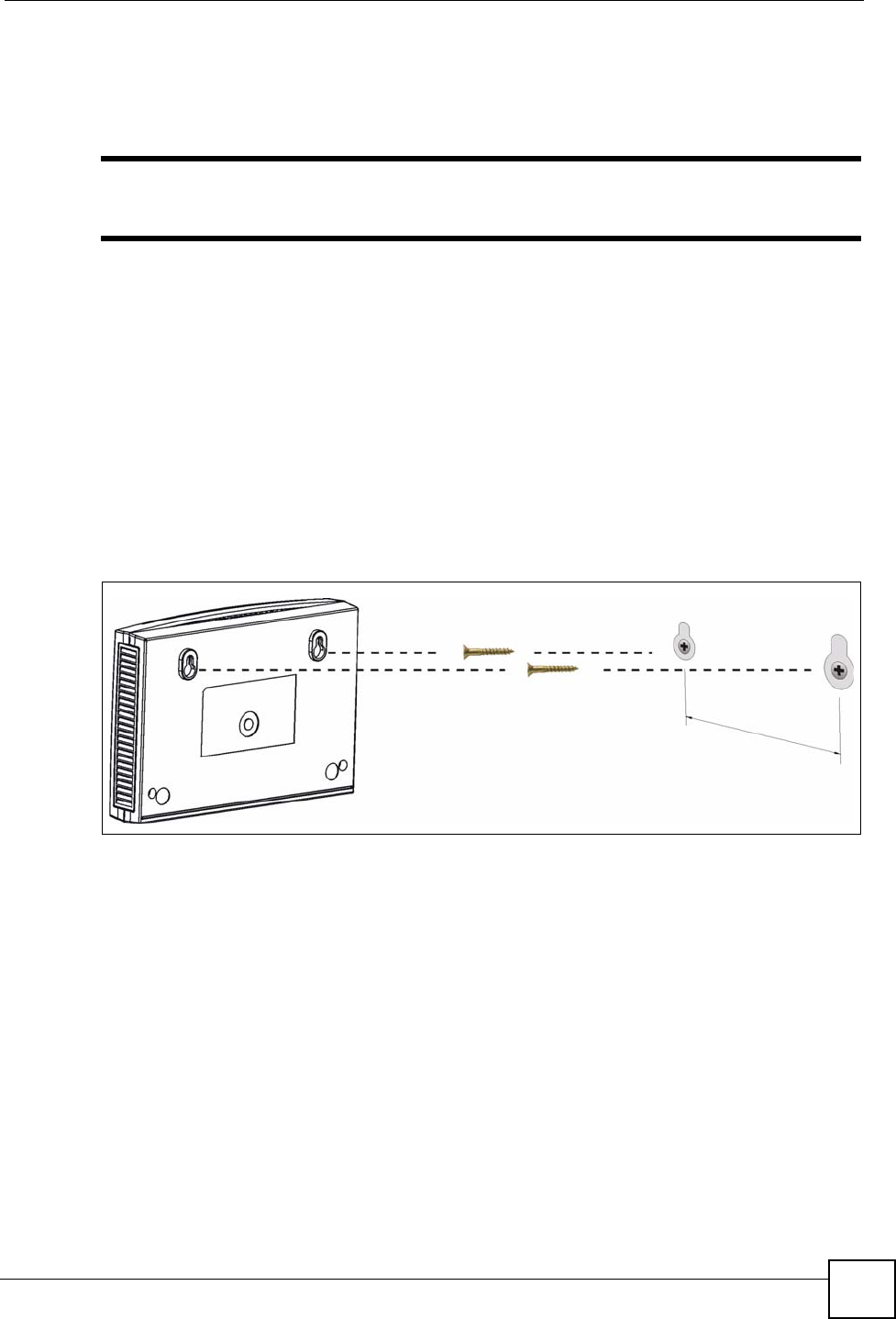
Appendix A Product Specifications and Wall Mounting
P-660HW-Dx v2 User’s Guide 269
Wall-mounting Instructions
Complete the following steps to hang your ZyXEL Device on a wall.
"See the Hardware Specifications table for the size of screws to use and how far
apart to place them.
1Select a high position on a sturdy wall that is free of obstructions.
2Drill two holes for the screws.
3Be careful to avoid damaging pipes or cables located inside the wall when drilling holes
for the screws.
4Do not insert the screws all the way into the wall. Leave a small gap of about 0.5 cm
between the heads of the screws and the wall.
5Make sure the screws are snugly fastened to the wall. They need to hold the weight of
the ZyXEL Device with the connection cables.
6Align the holes on the back of the ZyXEL Device with the screws on the wall. Hang the
ZyXEL Device on the screws.
Figure 154 Wall-mounting Example
The following are dimensions of an M4 tap screw and masonry plug used for wall mounting.
All measurements are in millimeters (mm).
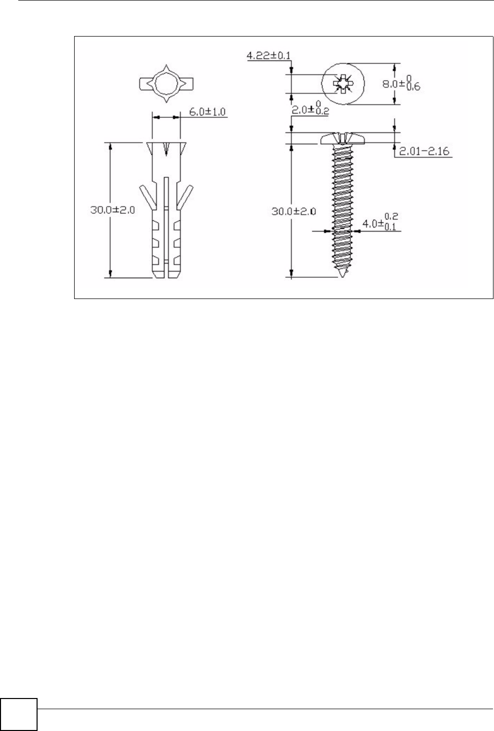
Appendix A Product Specifications and Wall Mounting
P-660HW-Dx v2 User’s Guide
270
Figure 155 Masonry Plug and M4 Tap Screw
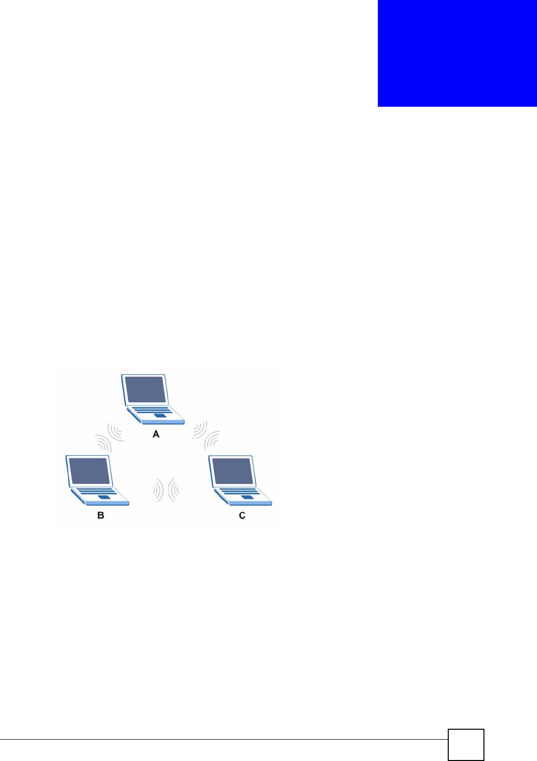
P-660HW-Dx v2 User’s Guide 271
APPENDIX B
Wireless LANs
Wireless LAN Topologies
This section discusses ad-hoc and infrastructure wireless LAN topologies.
Ad-hoc Wireless LAN Configuration
The simplest WLAN configuration is an independent (Ad-hoc) WLAN that connects a set of
computers with wireless adapters (A, B, C). Any time two or more wireless adapters are within
range of each other, they can set up an independent network, which is commonly referred to as
an ad-hoc network or Independent Basic Service Set (IBSS). The following diagram shows an
example of notebook computers using wireless adapters to form an ad-hoc wireless LAN.
Figure 156 Peer-to-Peer Communication in an Ad-hoc Network
BSS
A Basic Service Set (BSS) exists when all communications between wireless clients or
between a wireless client and a wired network client go through one access point (AP).
Intra-BSS traffic is traffic between wireless clients in the BSS. When Intra-BSS is enabled,
wireless client A and B can access the wired network and communicate with each other. When
Intra-BSS is disabled, wireless client A and B can still access the wired network but cannot
communicate with each other.
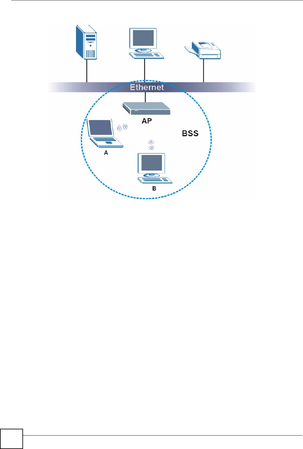
Appendix B Wireless LANs
P-660HW-Dx v2 User’s Guide
272
Figure 157 Basic Service Set
ESS
An Extended Service Set (ESS) consists of a series of overlapping BSSs, each containing an
access point, with each access point connected together by a wired network. This wired
connection between APs is called a Distribution System (DS).
This type of wireless LAN topology is called an Infrastructure WLAN. The Access Points not
only provide communication with the wired network but also mediate wireless network traffic
in the immediate neighborhood.
An ESSID (ESS IDentification) uniquely identifies each ESS. All access points and their
associated wireless clients within the same ESS must have the same ESSID in order to
communicate.
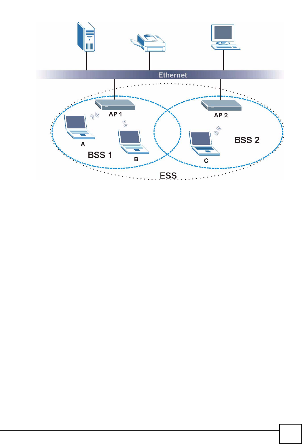
Appendix B Wireless LANs
P-660HW-Dx v2 User’s Guide 273
Figure 158 Infrastructure WLAN
Channel
A channel is the radio frequency(ies) used by wireless devices to transmit and receive data.
Channels available depend on your geographical area. You may have a choice of channels (for
your region) so you should use a channel different from an adjacent AP (access point) to
reduce interference. Interference occurs when radio signals from different access points
overlap causing interference and degrading performance.
Adjacent channels partially overlap however. To avoid interference due to overlap, your AP
should be on a channel at least five channels away from a channel that an adjacent AP is using.
For example, if your region has 11 channels and an adjacent AP is using channel 1, then you
need to select a channel between 6 or 11.
RTS/CTS
A hidden node occurs when two stations are within range of the same access point, but are not
within range of each other. The following figure illustrates a hidden node. Both stations (STA)
are within range of the access point (AP) or wireless gateway, but out-of-range of each other,
so they cannot "hear" each other, that is they do not know if the channel is currently being
used. Therefore, they are considered hidden from each other.
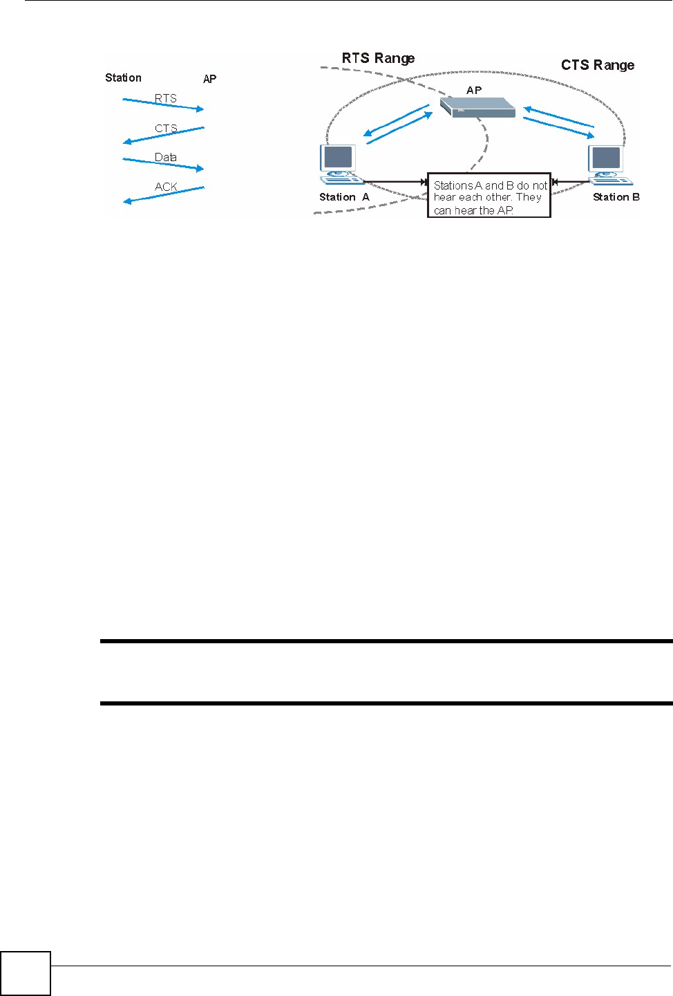
Appendix B Wireless LANs
P-660HW-Dx v2 User’s Guide
274
Figure 159 RTS/CTS
When station A sends data to the AP, it might not know that the station B is already using the
channel. If these two stations send data at the same time, collisions may occur when both sets
of data arrive at the AP at the same time, resulting in a loss of messages for both stations.
RTS/CTS is designed to prevent collisions due to hidden nodes. An RTS/CTS defines the
biggest size data frame you can send before an RTS (Request To Send)/CTS (Clear to Send)
handshake is invoked.
When a data frame exceeds the RTS/CTS value you set (between 0 to 2432 bytes), the station
that wants to transmit this frame must first send an RTS (Request To Send) message to the AP
for permission to send it. The AP then responds with a CTS (Clear to Send) message to all
other stations within its range to notify them to defer their transmission. It also reserves and
confirms with the requesting station the time frame for the requested transmission.
Stations can send frames smaller than the specified RTS/CTS directly to the AP without the
RTS (Request To Send)/CTS (Clear to Send) handshake.
You should only configure RTS/CTS if the possibility of hidden nodes exists on your network
and the "cost" of resending large frames is more than the extra network overhead involved in
the RTS (Request To Send)/CTS (Clear to Send) handshake.
If the RTS/CTS value is greater than the Fragmentation Threshold value (see next), then the
RTS (Request To Send)/CTS (Clear to Send) handshake will never occur as data frames will
be fragmented before they reach RTS/CTS size.
"Enabling the RTS Threshold causes redundant network overhead that could
negatively affect the throughput performance instead of providing a remedy.
Fragmentation Threshold
A Fragmentation Threshold is the maximum data fragment size (between 256 and 2432
bytes) that can be sent in the wireless network before the AP will fragment the packet into
smaller data frames.
A large Fragmentation Threshold is recommended for networks not prone to interference
while you should set a smaller threshold for busy networks or networks that are prone to
interference.

Appendix B Wireless LANs
P-660HW-Dx v2 User’s Guide 275
If the Fragmentation Threshold value is smaller than the RTS/CTS value (see previously)
you set then the RTS (Request To Send)/CTS (Clear to Send) handshake will never occur as
data frames will be fragmented before they reach RTS/CTS size.
Preamble Type
Preamble is used to signal that data is coming to the receiver. Short and long refer to the length
of the synchronization field in a packet.
Short preamble increases performance as less time sending preamble means more time for
sending data. All IEEE 802.11 compliant wireless adapters support long preamble, but not all
support short preamble.
Use long preamble if you are unsure what preamble mode other wireless devices on the
network support, and to provide more reliable communications in busy wireless networks.
Use short preamble if you are sure all wireless devices on the network support it, and to
provide more efficient communications.
Use the dynamic setting to automatically use short preamble when all wireless devices on the
network support it, otherwise the ZyXEL Device uses long preamble.
"The wireless devices MUST use the same preamble mode in order to
communicate.
IEEE 802.11g Wireless LAN
IEEE 802.11g is fully compatible with the IEEE 802.11b standard. This means an IEEE
802.11b adapter can interface directly with an IEEE 802.11g access point (and vice versa) at
11 Mbps or lower depending on range. IEEE 802.11g has several intermediate rate steps
between the maximum and minimum data rates. The IEEE 802.11g data rate and modulation
are as follows:
Wireless Security Overview
Wireless security is vital to your network to protect wireless communication between wireless
clients, access points and the wired network.
Table 121 IEEE 802.11g
DATA RATE (MBPS) MODULATION
1 DBPSK (Differential Binary Phase Shift Keyed)
2 DQPSK (Differential Quadrature Phase Shift Keying)
5.5 / 11 CCK (Complementary Code Keying)
6/9/12/18/24/36/48/54 OFDM (Orthogonal Frequency Division Multiplexing)
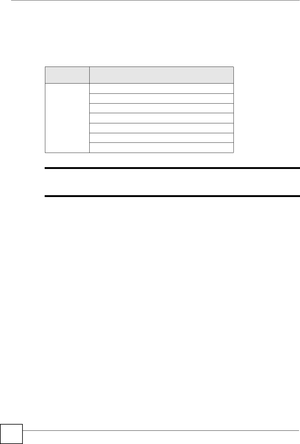
Appendix B Wireless LANs
P-660HW-Dx v2 User’s Guide
276
Wireless security methods available on the ZyXEL Device are data encryption, wireless client
authentication, restricting access by device MAC address and hiding the ZyXEL Device
identity.
The following figure shows the relative effectiveness of these wireless security methods
available on your ZyXEL Device.
"You must enable the same wireless security settings on the ZyXEL Device and
on all wireless clients that you want to associate with it.
IEEE 802.1x
In June 2001, the IEEE 802.1x standard was designed to extend the features of IEEE 802.11 to
support extended authentication as well as providing additional accounting and control
features. It is supported by Windows XP and a number of network devices. Some advantages
of IEEE 802.1x are:
• User based identification that allows for roaming.
• Support for RADIUS (Remote Authentication Dial In User Service, RFC 2138, 2139) for
centralized user profile and accounting management on a network RADIUS server.
• Support for EAP (Extensible Authentication Protocol, RFC 2486) that allows additional
authentication methods to be deployed with no changes to the access point or the wireless
clients.
RADIUS
RADIUS is based on a client-server model that supports authentication, authorization and
accounting. The access point is the client and the server is the RADIUS server. The RADIUS
server handles the following tasks:
• Authentication
Determines the identity of the users.
• Authorization
Table 122 Wireless Security Levels
SECURITY
LEVEL SECURITY TYPE
Least
S e c u r e
Most Secure
Unique SSID (Default)
Unique SSID with Hide SSID Enabled
MAC Address Filtering
WEP Encryption
IEEE802.1x EAP with RADIUS Server Authentication
Wi-Fi Protected Access (WPA)
WPA2

Appendix B Wireless LANs
P-660HW-Dx v2 User’s Guide 277
Determines the network services available to authenticated users once they are connected
to the network.
• Accounting
Keeps track of the client’s network activity.
RADIUS is a simple package exchange in which your AP acts as a message relay between the
wireless client and the network RADIUS server.
Types of RADIUS Messages
The following types of RADIUS messages are exchanged between the access point and the
RADIUS server for user authentication:
• Access-Request
Sent by an access point requesting authentication.
• Access-Reject
Sent by a RADIUS server rejecting access.
• Access-Accept
Sent by a RADIUS server allowing access.
• Access-Challenge
Sent by a RADIUS server requesting more information in order to allow access. The
access point sends a proper response from the user and then sends another Access-Request
message.
The following types of RADIUS messages are exchanged between the access point and the
RADIUS server for user accounting:
• Accounting-Request
Sent by the access point requesting accounting.
• Accounting-Response
Sent by the RADIUS server to indicate that it has started or stopped accounting.
In order to ensure network security, the access point and the RADIUS server use a shared
secret key, which is a password, they both know. The key is not sent over the network. In
addition to the shared key, password information exchanged is also encrypted to protect the
network from unauthorized access.
Types of EAP Authentication
This section discusses some popular authentication types: EAP-MD5, EAP-TLS, EAP-TTLS,
PEAP and LEAP. Your wireless LAN device may not support all authentication types.
EAP (Extensible Authentication Protocol) is an authentication protocol that runs on top of the
IEEE 802.1x transport mechanism in order to support multiple types of user authentication. By
using EAP to interact with an EAP-compatible RADIUS server, an access point helps a
wireless station and a RADIUS server perform authentication.
The type of authentication you use depends on the RADIUS server and an intermediary AP(s)
that supports IEEE 802.1x. .

Appendix B Wireless LANs
P-660HW-Dx v2 User’s Guide
278
For EAP-TLS authentication type, you must first have a wired connection to the network and
obtain the certificate(s) from a certificate authority (CA). A certificate (also called digital IDs)
can be used to authenticate users and a CA issues certificates and guarantees the identity of
each certificate owner.
EAP-MD5 (Message-Digest Algorithm 5)
MD5 authentication is the simplest one-way authentication method. The authentication server
sends a challenge to the wireless client. The wireless client ‘proves’ that it knows the password
by encrypting the password with the challenge and sends back the information. Password is
not sent in plain text.
However, MD5 authentication has some weaknesses. Since the authentication server needs to
get the plaintext passwords, the passwords must be stored. Thus someone other than the
authentication server may access the password file. In addition, it is possible to impersonate an
authentication server as MD5 authentication method does not perform mutual authentication.
Finally, MD5 authentication method does not support data encryption with dynamic session
key. You must configure WEP encryption keys for data encryption.
EAP-TLS (Transport Layer Security)
With EAP-TLS, digital certifications are needed by both the server and the wireless clients for
mutual authentication. The server presents a certificate to the client. After validating the
identity of the server, the client sends a different certificate to the server. The exchange of
certificates is done in the open before a secured tunnel is created. This makes user identity
vulnerable to passive attacks. A digital certificate is an electronic ID card that authenticates the
sender’s identity. However, to implement EAP-TLS, you need a Certificate Authority (CA) to
handle certificates, which imposes a management overhead.
EAP-TTLS (Tunneled Transport Layer Service)
EAP-TTLS is an extension of the EAP-TLS authentication that uses certificates for only the
server-side authentications to establish a secure connection. Client authentication is then done
by sending username and password through the secure connection, thus client identity is
protected. For client authentication, EAP-TTLS supports EAP methods and legacy
authentication methods such as PAP, CHAP, MS-CHAP and MS-CHAP v2.
PEAP (Protected EAP)
Like EAP-TTLS, server-side certificate authentication is used to establish a secure connection,
then use simple username and password methods through the secured connection to
authenticate the clients, thus hiding client identity. However, PEAP only supports EAP
methods, such as EAP-MD5, EAP-MSCHAPv2 and EAP-GTC (EAP-Generic Token Card),
for client authentication. EAP-GTC is implemented only by Cisco.
LEAP
LEAP (Lightweight Extensible Authentication Protocol) is a Cisco implementation of IEEE
802.1x.

Appendix B Wireless LANs
P-660HW-Dx v2 User’s Guide 279
Dynamic WEP Key Exchange
The AP maps a unique key that is generated with the RADIUS server. This key expires when
the wireless connection times out, disconnects or reauthentication times out. A new WEP key
is generated each time reauthentication is performed.
If this feature is enabled, it is not necessary to configure a default encryption key in the
wireless security configuration screen. You may still configure and store keys, but they will
not be used while dynamic WEP is enabled.
"EAP-MD5 cannot be used with Dynamic WEP Key Exchange
For added security, certificate-based authentications (EAP-TLS, EAP-TTLS and PEAP) use
dynamic keys for data encryption. They are often deployed in corporate environments, but for
public deployment, a simple user name and password pair is more practical. The following
table is a comparison of the features of authentication types.
WPA and WPA2
Wi-Fi Protected Access (WPA) is a subset of the IEEE 802.11i standard. WPA2 (IEEE
802.11i) is a wireless security standard that defines stronger encryption, authentication and
key management than WPA.
Key differences between WPA or WPA2 and WEP are improved data encryption and user
authentication.
If both an AP and the wireless clients support WPA2 and you have an external RADIUS
server, use WPA2 for stronger data encryption. If you don't have an external RADIUS server,
you should use WPA2-PSK (WPA2-Pre-Shared Key) that only requires a single (identical)
password entered into each access point, wireless gateway and wireless client. As long as the
passwords match, a wireless client will be granted access to a WLAN.
If the AP or the wireless clients do not support WPA2, just use WPA or WPA-PSK depending
on whether you have an external RADIUS server or not.
Select WEP only when the AP and/or wireless clients do not support WPA or WPA2. WEP is
less secure than WPA or WPA2.
Table 123 Comparison of EAP Authentication Types
EAP-MD5 EAP-TLS EAP-TTLS PEAP LEAP
Mutual Authentication No Yes Yes Yes Yes
Certificate – Client No Yes Optional Optional No
Certificate – Server No Yes Yes Yes No
Dynamic Key Exchange No Yes Yes Yes Yes
Credential Integrity None Strong Strong Strong Moderate
Deployment Difficulty Easy Hard Moderate Moderate Moderate
Client Identity Protection No No Yes Yes No

Appendix B Wireless LANs
P-660HW-Dx v2 User’s Guide
280
Encryption
Both WPA and WPA2 improve data encryption by using Temporal Key Integrity Protocol
(TKIP), Message Integrity Check (MIC) and IEEE 802.1x. WPA and WPA2 use Advanced
Encryption Standard (AES) in the Counter mode with Cipher block chaining Message
authentication code Protocol (CCMP) to offer stronger encryption than TKIP.
TKIP uses 128-bit keys that are dynamically generated and distributed by the authentication
server. AES (Advanced Encryption Standard) is a block cipher that uses a 256-bit
mathematical algorithm called Rijndael. They both include a per-packet key mixing function,
a Message Integrity Check (MIC) named Michael, an extended initialization vector (IV) with
sequencing rules, and a re-keying mechanism.
WPA and WPA2 regularly change and rotate the encryption keys so that the same encryption
key is never used twice.
The RADIUS server distributes a Pairwise Master Key (PMK) key to the AP that then sets up
a key hierarchy and management system, using the PMK to dynamically generate unique data
encryption keys to encrypt every data packet that is wirelessly communicated between the AP
and the wireless clients. This all happens in the background automatically.
The Message Integrity Check (MIC) is designed to prevent an attacker from capturing data
packets, altering them and resending them. The MIC provides a strong mathematical function
in which the receiver and the transmitter each compute and then compare the MIC. If they do
not match, it is assumed that the data has been tampered with and the packet is dropped.
By generating unique data encryption keys for every data packet and by creating an integrity
checking mechanism (MIC), with TKIP and AES it is more difficult to decrypt data on a Wi-Fi
network than WEP and difficult for an intruder to break into the network.
The encryption mechanisms used for WPA(2) and WPA(2)-PSK are the same. The only
difference between the two is that WPA(2)-PSK uses a simple common password, instead of
user-specific credentials. The common-password approach makes WPA(2)-PSK susceptible to
brute-force password-guessing attacks but it’s still an improvement over WEP as it employs a
consistent, single, alphanumeric password to derive a PMK which is used to generate unique
temporal encryption keys. This prevent all wireless devices sharing the same encryption keys.
(a weakness of WEP)
User Authentication
WPA and WPA2 apply IEEE 802.1x and Extensible Authentication Protocol (EAP) to
authenticate wireless clients using an external RADIUS database. WPA2 reduces the number
of key exchange messages from six to four (CCMP 4-way handshake) and shortens the time
required to connect to a network. Other WPA2 authentication features that are different from
WPA include key caching and pre-authentication. These two features are optional and may not
be supported in all wireless devices.
Key caching allows a wireless client to store the PMK it derived through a successful
authentication with an AP. The wireless client uses the PMK when it tries to connect to the
same AP and does not need to go with the authentication process again.
Pre-authentication enables fast roaming by allowing the wireless client (already connecting to
an AP) to perform IEEE 802.1x authentication with another AP before connecting to it.
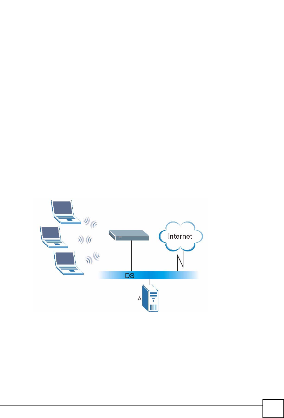
Appendix B Wireless LANs
P-660HW-Dx v2 User’s Guide 281
Wireless Client WPA Supplicants
A wireless client supplicant is the software that runs on an operating system instructing the
wireless client how to use WPA. At the time of writing, the most widely available supplicant is
the WPA patch for Windows XP, Funk Software's Odyssey client.
The Windows XP patch is a free download that adds WPA capability to Windows XP's built-
in "Zero Configuration" wireless client. However, you must run Windows XP to use it.
WPA(2) with RADIUS Application Example
To set up WPA(2), you need the IP address of the RADIUS server, its port number (default is
1812), and the RADIUS shared secret. A WPA(2) application example with an external
RADIUS server looks as follows. "A" is the RADIUS server. "DS" is the distribution system.
1The AP passes the wireless client's authentication request to the RADIUS server.
2The RADIUS server then checks the user's identification against its database and grants
or denies network access accordingly.
3A 256-bit Pairwise Master Key (PMK) is derived from the authentication process by the
RADIUS server and the client.
4The RADIUS server distributes the PMK to the AP. The AP then sets up a key hierarchy
and management system, using the PMK to dynamically generate unique data encryption
keys. The keys are used to encrypt every data packet that is wirelessly communicated
between the AP and the wireless clients.
Figure 160 WPA(2) with RADIUS Application Example
WPA(2)-PSK Application Example
A WPA(2)-PSK application looks as follows.
1First enter identical passwords into the AP and all wireless clients. The Pre-Shared Key
(PSK) must consist of between 8 and 63 ASCII characters or 64 hexadecimal characters
(including spaces and symbols).
2The AP checks each wireless client's password and allows it to join the network only if
the password matches.
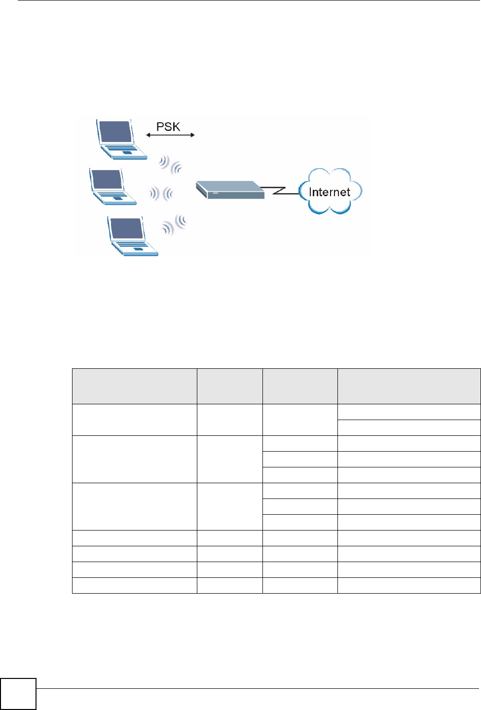
Appendix B Wireless LANs
P-660HW-Dx v2 User’s Guide
282
3The AP and wireless clients generate a common PMK (Pairwise Master Key). The key
itself is not sent over the network, but is derived from the PSK and the SSID.
4The AP and wireless clients use the TKIP or AES encryption process, the PMK and
information exchanged in a handshake to create temporal encryption keys. They use
these keys to encrypt data exchanged between them.
Figure 161 WPA(2)-PSK Authentication
Security Parameters Summary
Refer to this table to see what other security parameters you should configure for each
authentication method or key management protocol type. MAC address filters are not
dependent on how you configure these security features.
Table 124 Wireless Security Relational Matrix
AUTHENTICATION
METHOD/ KEY
MANAGEMENT PROTOCOL
ENCRYPTIO
N METHOD
ENTER
MANUAL KEY IEEE 802.1X
Open None No Disable
Enable without Dynamic WEP Key
Open WEP No Enable with Dynamic WEP Key
Yes Enable without Dynamic WEP Key
Yes Disable
Shared WEP No Enable with Dynamic WEP Key
Yes Enable without Dynamic WEP Key
Yes Disable
WPA TKIP/AES No Enable
WPA-PSK TKIP/AES Yes Disable
WPA2 TKIP/AES No Enable
WPA2-PSK TKIP/AES Yes Disable

Appendix B Wireless LANs
P-660HW-Dx v2 User’s Guide 283
Antenna Overview
An antenna couples RF signals onto air. A transmitter within a wireless device sends an RF
signal to the antenna, which propagates the signal through the air. The antenna also operates in
reverse by capturing RF signals from the air.
Positioning the antennas properly increases the range and coverage area of a wireless LAN.
Antenna Characteristics
Frequency
An antenna in the frequency of 2.4GHz (IEEE 802.11b and IEEE 802.11g) or 5GHz (IEEE
802.11a) is needed to communicate efficiently in a wireless LAN
Radiation Pattern
A radiation pattern is a diagram that allows you to visualize the shape of the antenna’s
coverage area.
Antenna Gain
Antenna gain, measured in dB (decibel), is the increase in coverage within the RF beam width.
Higher antenna gain improves the range of the signal for better communications.
For an indoor site, each 1 dB increase in antenna gain results in a range increase of
approximately 2.5%. For an unobstructed outdoor site, each 1dB increase in gain results in a
range increase of approximately 5%. Actual results may vary depending on the network
environment.
Antenna gain is sometimes specified in dBi, which is how much the antenna increases the
signal power compared to using an isotropic antenna. An isotropic antenna is a theoretical
perfect antenna that sends out radio signals equally well in all directions. dBi represents the
true gain that the antenna provides.
Types of Antennas for WLAN
There are two types of antennas used for wireless LAN applications.
• Omni-directional antennas send the RF signal out in all directions on a horizontal plane.
The coverage area is torus-shaped (like a donut) which makes these antennas ideal for a
room environment. With a wide coverage area, it is possible to make circular overlapping
coverage areas with multiple access points.
• Directional antennas concentrate the RF signal in a beam, like a flashlight does with the
light from its bulb. The angle of the beam determines the width of the coverage pattern.
Angles typically range from 20 degrees (very directional) to 120 degrees (less directional).
Directional antennas are ideal for hallways and outdoor point-to-point applications.

Appendix B Wireless LANs
P-660HW-Dx v2 User’s Guide
284
Positioning Antennas
In general, antennas should be mounted as high as practically possible and free of
obstructions. In point-to–point application, position both antennas at the same height and in a
direct line of sight to each other to attain the best performance.
For omni-directional antennas mounted on a table, desk, and so on, point the antenna up. For
omni-directional antennas mounted on a wall or ceiling, point the antenna down. For a single
AP application, place omni-directional antennas as close to the center of the coverage area as
possible.
For directional antennas, point the antenna in the direction of the desired coverage area.

P-660HW-Dx v2 User’s Guide 285
APPENDIX C
Setting up Your Computer’s IP
Address
All computers must have a 10M or 100M Ethernet adapter card and TCP/IP installed.
Windows 95/98/Me/NT/2000/XP, Macintosh OS 7 and later operating systems and all
versions of UNIX/LINUX include the software components you need to install and use TCP/
IP on your computer. Windows 3.1 requires the purchase of a third-party TCP/IP application
package.
TCP/IP should already be installed on computers using Windows NT/2000/XP, Macintosh OS
7 and later operating systems.
After the appropriate TCP/IP components are installed, configure the TCP/IP settings in order
to "communicate" with your network.
If you manually assign IP information instead of using dynamic assignment, make sure that
your computers have IP addresses that place them in the same subnet as the ZyXEL Device’s
LAN port.
Windows 95/98/Me
Click Start, Settings, Control Panel and double-click the Network icon to open the Network
window.
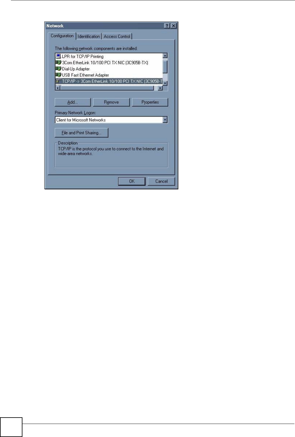
Appendix C Setting up Your Computer’s IP Address
P-660HW-Dx v2 User’s Guide
286
Figure 162 WIndows 95/98/Me: Network: Configuration
Installing Components
The Network window Configuration tab displays a list of installed components. You need a
network adapter, the TCP/IP protocol and Client for Microsoft Networks.
If you need the adapter:
1In the Network window, click Add.
2Select Adapter and then click Add.
3Select the manufacturer and model of your network adapter and then click OK.
If you need TCP/IP:
1In the Network window, click Add.
2Select Protocol and then click Add.
3Select Microsoft from the list of manufacturers.
4Select TCP/IP from the list of network protocols and then click OK.
If you need Client for Microsoft Networks:
1Click Add.
2Select Client and then click Add.
3Select Microsoft from the list of manufacturers.
4Select Client for Microsoft Networks from the list of network clients and then click
OK.
5Restart your computer so the changes you made take effect.
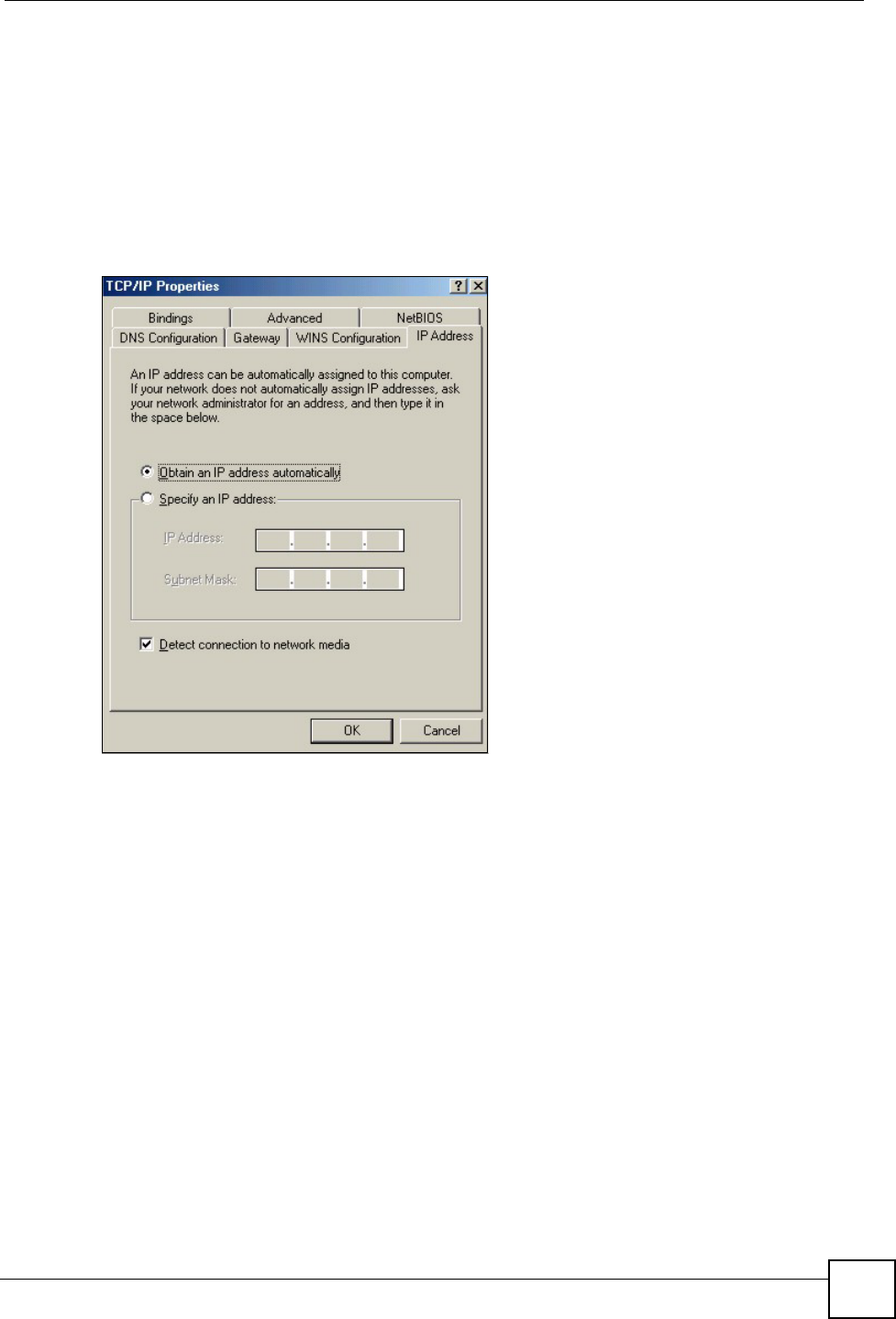
Appendix C Setting up Your Computer’s IP Address
P-660HW-Dx v2 User’s Guide 287
Configuring
1In the Network window Configuration tab, select your network adapter's TCP/IP entry
and click Properties
2Click the IP Address tab.
• If your IP address is dynamic, select Obtain an IP address automatically.
• If you have a static IP address, select Specify an IP address and type your
information into the IP Address and Subnet Mask fields.
Figure 163 Windows 95/98/Me: TCP/IP Properties: IP Address
3Click the DNS Configuration tab.
• If you do not know your DNS information, select Disable DNS.
• If you know your DNS information, select Enable DNS and type the information in
the fields below (you may not need to fill them all in).
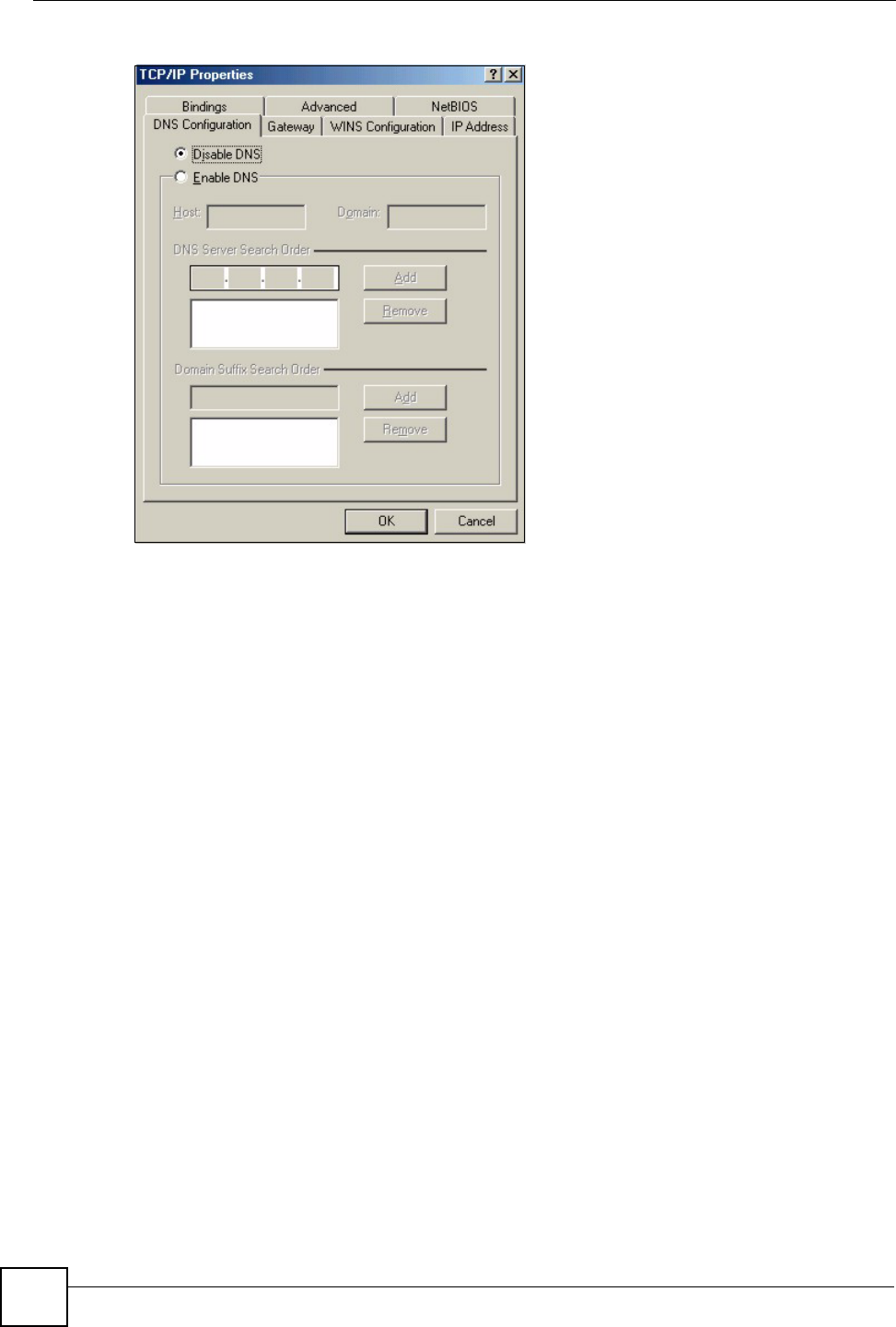
Appendix C Setting up Your Computer’s IP Address
P-660HW-Dx v2 User’s Guide
288
Figure 164 Windows 95/98/Me: TCP/IP Properties: DNS Configuration
4Click the Gateway tab.
• If you do not know your gateway’s IP address, remove previously installed gateways.
• If you have a gateway IP address, type it in the New gateway field and click Add.
5Click OK to save and close the TCP/IP Properties window.
6Click OK to close the Network window. Insert the Windows CD if prompted.
7Turn on your ZyXEL Device and restart your computer when prompted.
Verifying Settings
1Click Start and then Run.
2In the Run window, type "winipcfg" and then click OK to open the IP Configuration
window.
3Select your network adapter. You should see your computer's IP address, subnet mask
and default gateway.
Windows 2000/NT/XP
The following example figures use the default Windows XP GUI theme.
1Click start (Start in Windows 2000/NT), Settings, Control Panel.
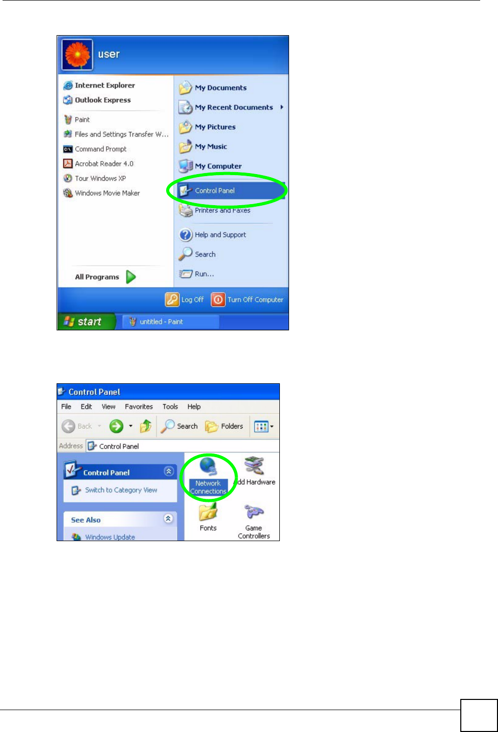
Appendix C Setting up Your Computer’s IP Address
P-660HW-Dx v2 User’s Guide 289
Figure 165 Windows XP: Start Menu
2In the Control Panel, double-click Network Connections (Network and Dial-up
Connections in Windows 2000/NT).
Figure 166 Windows XP: Control Panel
3Right-click Local Area Connection and then click Properties.
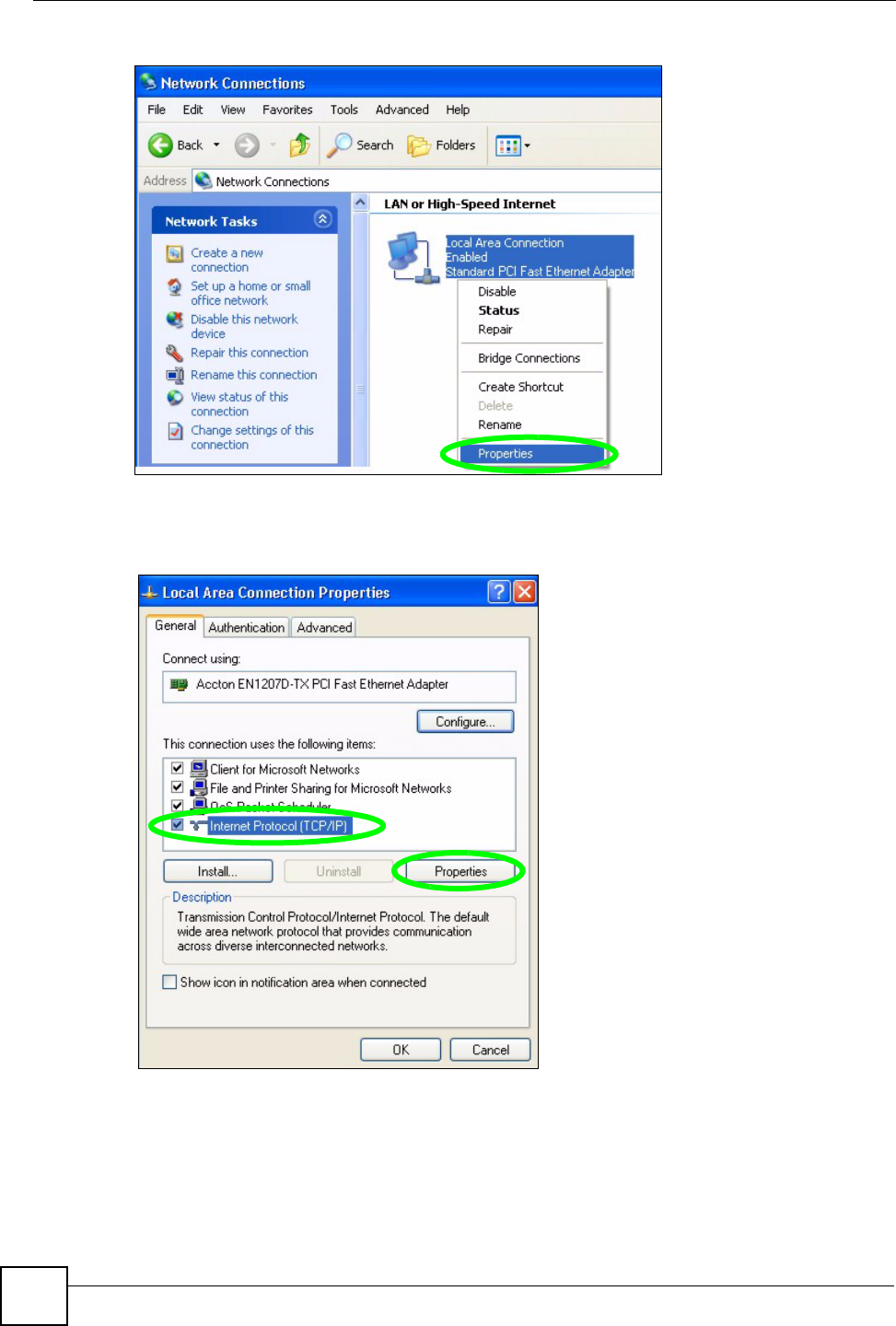
Appendix C Setting up Your Computer’s IP Address
P-660HW-Dx v2 User’s Guide
290
Figure 167 Windows XP: Control Panel: Network Connections: Properties
4Select Internet Protocol (TCP/IP) (under the General tab in Win XP) and then click
Properties.
Figure 168 Windows XP: Local Area Connection Properties
5The Internet Protocol TCP/IP Properties window opens (the General tab in
Windows XP).
• If you have a dynamic IP address click Obtain an IP address automatically.
• If you have a static IP address click Use the following IP Address and fill in the IP
address, Subnet mask, and Default gateway fields.
• Click Advanced.
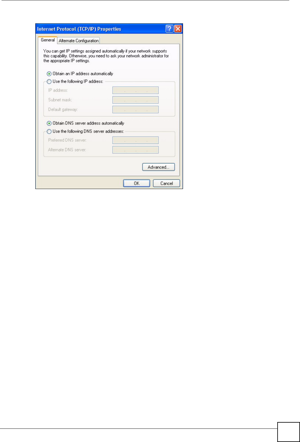
Appendix C Setting up Your Computer’s IP Address
P-660HW-Dx v2 User’s Guide 291
Figure 169 Windows XP: Internet Protocol (TCP/IP) Properties
6 If you do not know your gateway's IP address, remove any previously installed
gateways in the IP Settings tab and click OK.
Do one or more of the following if you want to configure additional IP addresses:
•In the IP Settings tab, in IP addresses, click Add.
•In TCP/IP Address, type an IP address in IP address and a subnet mask in Subnet
mask, and then click Add.
• Repeat the above two steps for each IP address you want to add.
• Configure additional default gateways in the IP Settings tab by clicking Add in
Default gateways.
•In TCP/IP Gateway Address, type the IP address of the default gateway in Gateway.
To manually configure a default metric (the number of transmission hops), clear the
Automatic metric check box and type a metric in Metric.
• Click Add.
• Repeat the previous three steps for each default gateway you want to add.
• Click OK when finished.
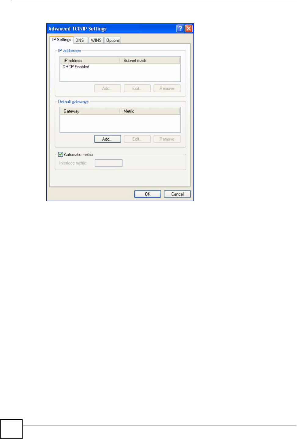
Appendix C Setting up Your Computer’s IP Address
P-660HW-Dx v2 User’s Guide
292
Figure 170 Windows XP: Advanced TCP/IP Properties
7In the Internet Protocol TCP/IP Properties window (the General tab in Windows
XP):
• Click Obtain DNS server address automatically if you do not know your DNS
server IP address(es).
• If you know your DNS server IP address(es), click Use the following DNS server
addresses, and type them in the Preferred DNS server and Alternate DNS server
fields.
If you have previously configured DNS servers, click Advanced and then the DNS
tab to order them.

Appendix C Setting up Your Computer’s IP Address
P-660HW-Dx v2 User’s Guide 293
Figure 171 Windows XP: Internet Protocol (TCP/IP) Properties
8Click OK to close the Internet Protocol (TCP/IP) Properties window.
9Click Close (OK in Windows 2000/NT) to close the Local Area Connection
Properties window.
10 Close the Network Connections window (Network and Dial-up Connections in
Windows 2000/NT).
11 Turn on your ZyXEL Device and restart your computer (if prompted).
Verifying Settings
1Click Start, All Programs, Accessories and then Command Prompt.
2In the Command Prompt window, type "ipconfig" and then press [ENTER]. You can
also open Network Connections, right-click a network connection, click Status and
then click the Support tab.
Macintosh OS 8/9
1Click the Apple menu, Control Panel and double-click TCP/IP to open the TCP/IP
Control Panel.
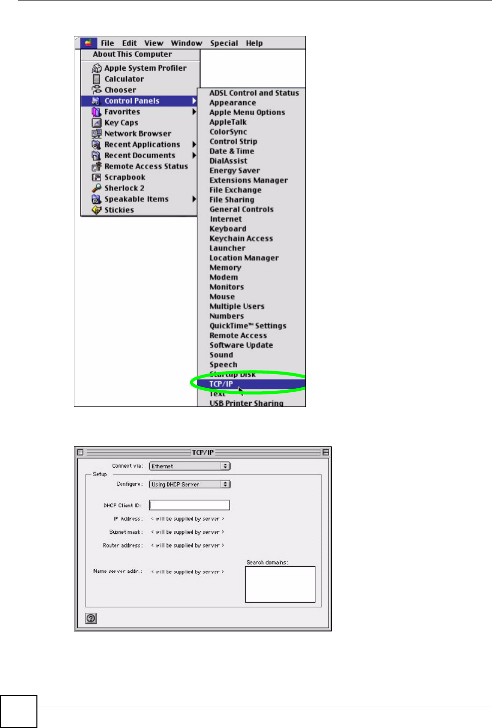
Appendix C Setting up Your Computer’s IP Address
P-660HW-Dx v2 User’s Guide
294
Figure 172 Macintosh OS 8/9: Apple Menu
2Select Ethernet built-in from the Connect via list.
Figure 173 Macintosh OS 8/9: TCP/IP
3For dynamically assigned settings, select Using DHCP Server from the Configure: list.
4For statically assigned settings, do the following:
•From the Configure box, select Manually.
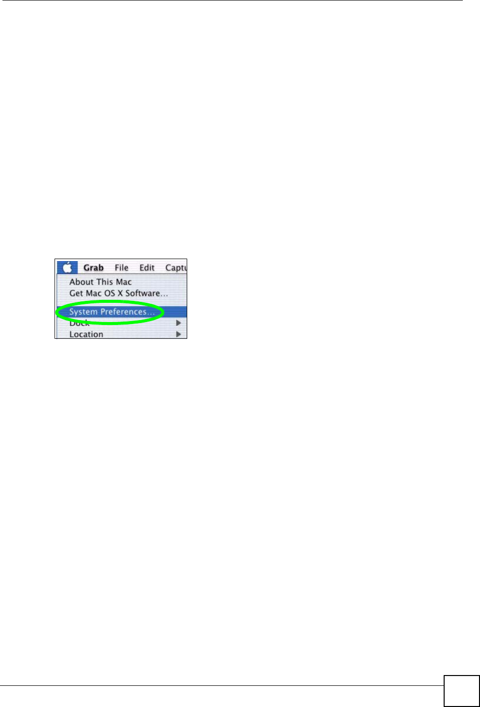
Appendix C Setting up Your Computer’s IP Address
P-660HW-Dx v2 User’s Guide 295
• Type your IP address in the IP Address box.
• Type your subnet mask in the Subnet mask box.
• Type the IP address of your ZyXEL Device in the Router address box.
5Close the TCP/IP Control Panel.
6Click Save if prompted, to save changes to your configuration.
7Turn on your ZyXEL Device and restart your computer (if prompted).
Verifying Settings
Check your TCP/IP properties in the TCP/IP Control Panel window.
Macintosh OS X
1Click the Apple menu, and click System Preferences to open the System Preferences
window.
Figure 174 Macintosh OS X: Apple Menu
2Click Network in the icon bar.
• Select Automatic from the Location list.
• Select Built-in Ethernet from the Show list.
• Click the TCP/IP tab.
3For dynamically assigned settings, select Using DHCP from the Configure list.
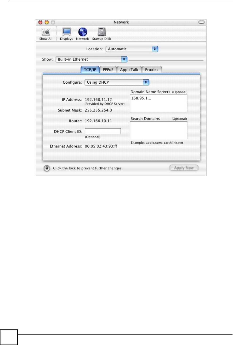
Appendix C Setting up Your Computer’s IP Address
P-660HW-Dx v2 User’s Guide
296
Figure 175 Macintosh OS X: Network
4For statically assigned settings, do the following:
•From the Configure box, select Manually.
• Type your IP address in the IP Address box.
• Type your subnet mask in the Subnet mask box.
• Type the IP address of your ZyXEL Device in the Router address box.
5Click Apply Now and close the window.
6Turn on your ZyXEL Device and restart your computer (if prompted).
Verifying Settings
Check your TCP/IP properties in the Network window.
Linux
This section shows you how to configure your computer’s TCP/IP settings in Red Hat Linux
9.0. Procedure, screens and file location may vary depending on your Linux distribution and
release version.
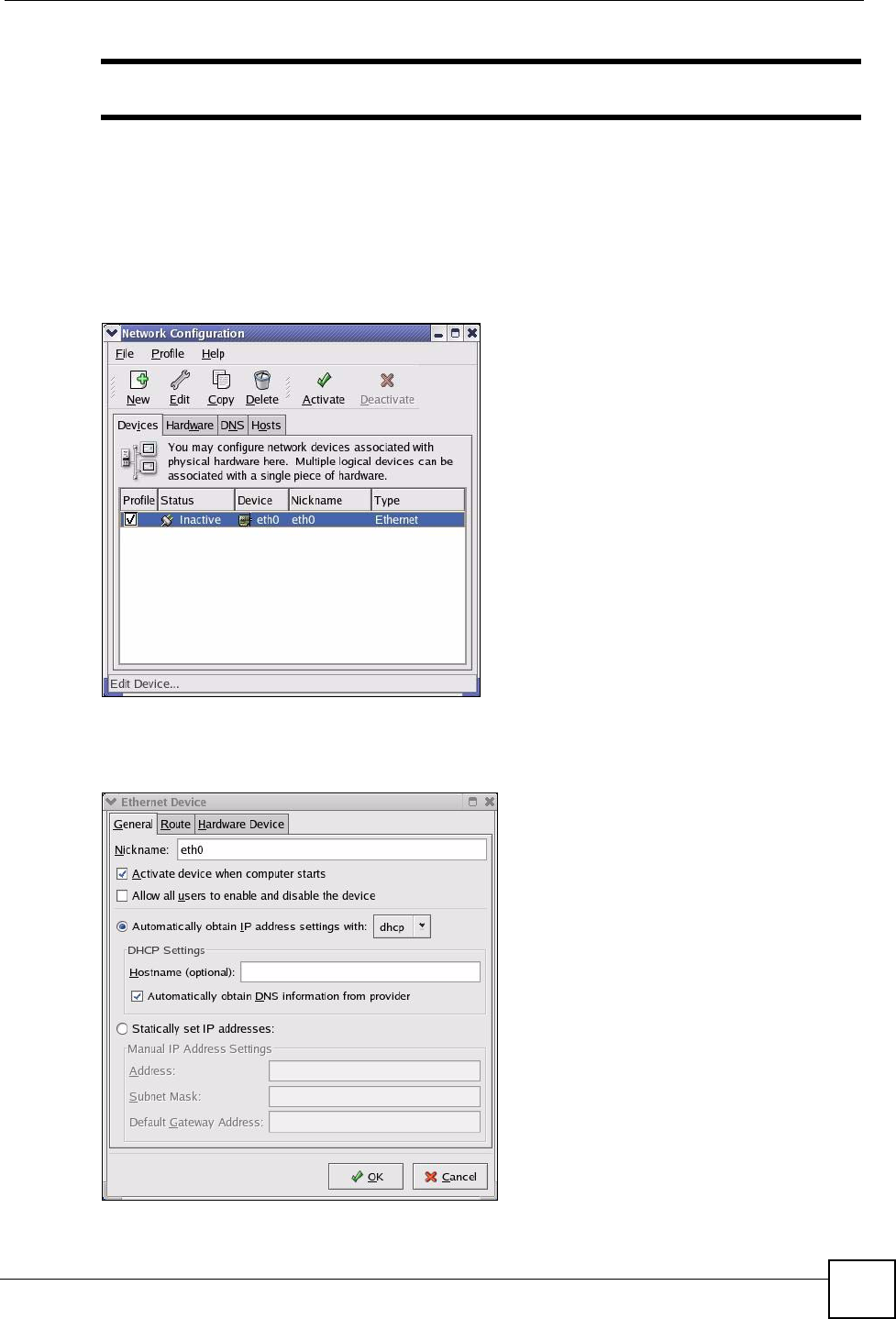
Appendix C Setting up Your Computer’s IP Address
P-660HW-Dx v2 User’s Guide 297
"Make sure you are logged in as the root administrator.
Using the K Desktop Environment (KDE)
Follow the steps below to configure your computer IP address using the KDE.
1Click the Red Hat button (located on the bottom left corner), select System Setting and
click Network.
Figure 176 Red Hat 9.0: KDE: Network Configuration: Devices
2Double-click on the profile of the network card you wish to configure. The Ethernet
Device General screen displays as shown.
Figure 177 Red Hat 9.0: KDE: Ethernet Device: General
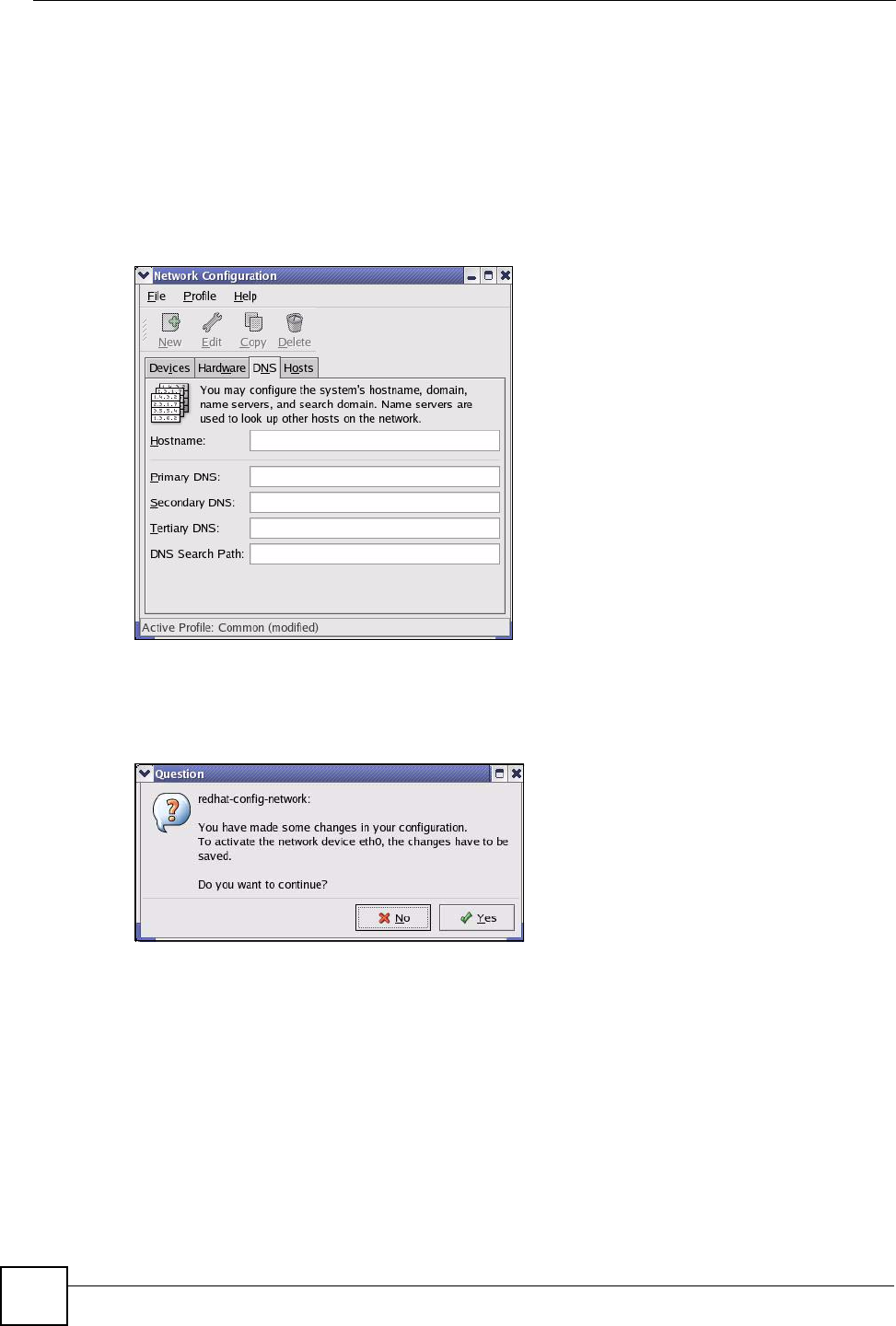
Appendix C Setting up Your Computer’s IP Address
P-660HW-Dx v2 User’s Guide
298
• If you have a dynamic IP address click Automatically obtain IP address settings
with and select dhcp from the drop down list.
• If you have a static IP address click Statically set IP Addresses and fill in the
Address, Subnet mask, and Default Gateway Address fields.
3Click OK to save the changes and close the Ethernet Device General screen.
4If you know your DNS server IP address(es), click the DNS tab in the Network
Configuration screen. Enter the DNS server information in the fields provided.
Figure 178 Red Hat 9.0: KDE: Network Configuration: DNS
5Click the Devices tab.
6Click the Activate button to apply the changes. The following screen displays. Click Yes
to save the changes in all screens.
Figure 179 Red Hat 9.0: KDE: Network Configuration: Activate
7After the network card restart process is complete, make sure the Status is Active in the
Network Configuration screen.
Using Configuration Files
Follow the steps below to edit the network configuration files and set your computer IP
address.
1Assuming that you have only one network card on the computer, locate the ifconfig-
eth0 configuration file (where eth0 is the name of the Ethernet card). Open the
configuration file with any plain text editor.
• If you have a dynamic IP address, enter dhcp in the BOOTPROTO= field. The following
figure shows an example.
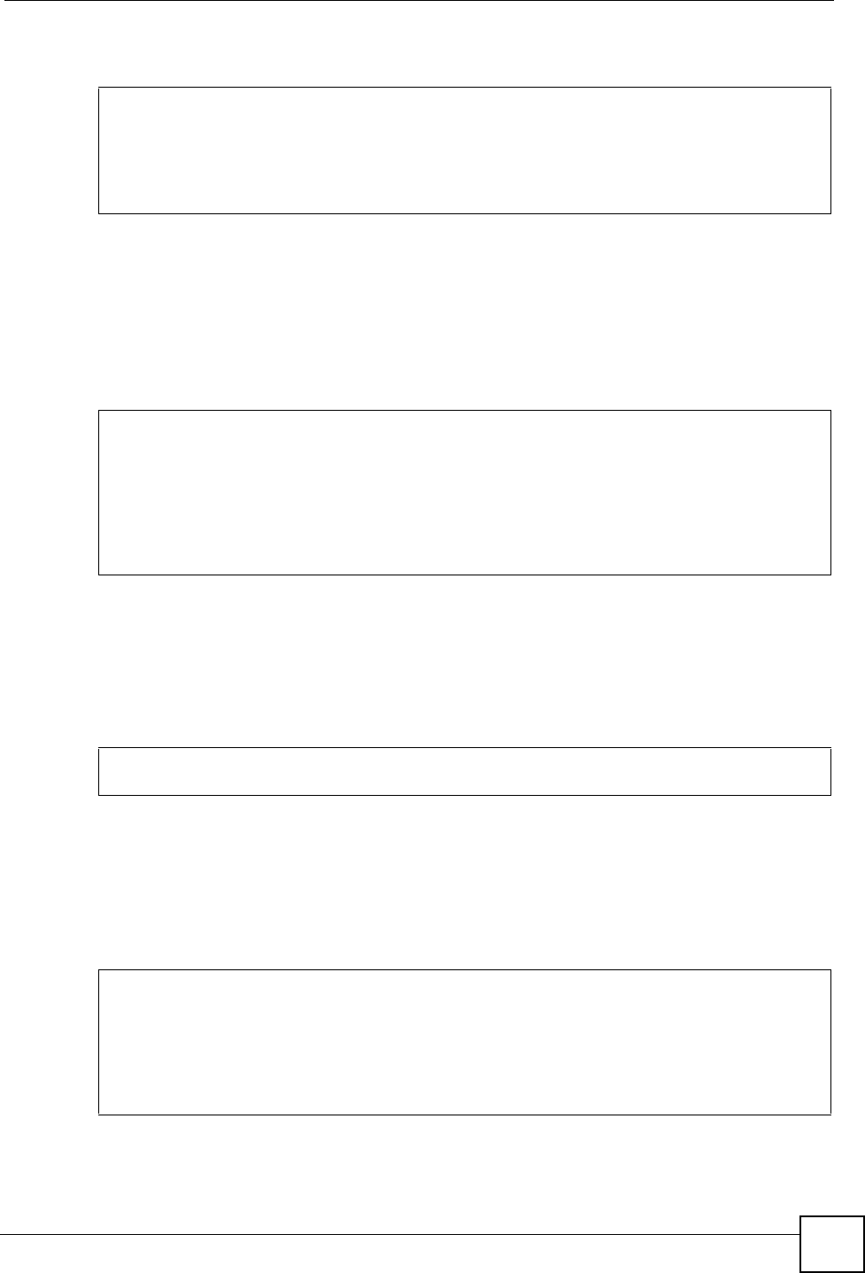
Appendix C Setting up Your Computer’s IP Address
P-660HW-Dx v2 User’s Guide 299
Figure 180 Red Hat 9.0: Dynamic IP Address Setting in ifconfig-eth0
• If you have a static IP address, enter static in the BOOTPROTO= field. Type
IPADDR= followed by the IP address (in dotted decimal notation) and type NETMASK=
followed by the subnet mask. The following example shows an example where the
static IP address is 192.168.1.10 and the subnet mask is 255.255.255.0.
Figure 181 Red Hat 9.0: Static IP Address Setting in ifconfig-eth0
2If you know your DNS server IP address(es), enter the DNS server information in the
resolv.conf file in the /etc directory. The following figure shows an example where
two DNS server IP addresses are specified.
Figure 182 Red Hat 9.0: DNS Settings in resolv.conf
3After you edit and save the configuration files, you must restart the network card. Enter
./network restart in the /etc/rc.d/init.d directory. The following figure
shows an example.
Figure 183 Red Hat 9.0: Restart Ethernet Card
DEVICE=eth0
ONBOOT=yes
BOOTPROTO=dhcp
USERCTL=no
PEERDNS=yes
TYPE=Ethernet
DEVICE=eth0
ONBOOT=yes
BOOTPROTO=static
IPADDR=192.168.1.10
NETMASK=255.255.255.0
USERCTL=no
PEERDNS=yes
TYPE=Ethernet
nameserver 172.23.5.1
nameserver 172.23.5.2
[root@localhost init.d]# network restart
Shutting down interface eth0: [OK]
Shutting down loopback interface: [OK]
Setting network parameters: [OK]
Bringing up loopback interface: [OK]
Bringing up interface eth0: [OK]

Appendix C Setting up Your Computer’s IP Address
P-660HW-Dx v2 User’s Guide
300
Verifying Settings
Enter ifconfig in a terminal screen to check your TCP/IP properties.
Figure 184 Red Hat 9.0: Checking TCP/IP Properties
[root@localhost]# ifconfig
eth0 Link encap:Ethernet HWaddr 00:50:BA:72:5B:44
inet addr:172.23.19.129 Bcast:172.23.19.255 Mask:255.255.255.0
UP BROADCAST RUNNING MULTICAST MTU:1500 Metric:1
RX packets:717 errors:0 dropped:0 overruns:0 frame:0
TX packets:13 errors:0 dropped:0 overruns:0 carrier:0
collisions:0 txqueuelen:100
RX bytes:730412 (713.2 Kb) TX bytes:1570 (1.5 Kb)
Interrupt:10 Base address:0x1000
[root@localhost]#