ZyXEL Communications P660HWDXV2 802.11g Wireless ADSL Gateway User Manual SMG 700 User s Guide V1 00 Nov 2004
ZyXEL Communications Corporation 802.11g Wireless ADSL Gateway SMG 700 User s Guide V1 00 Nov 2004
Part4

P-660HW-Dx v2 User’s Guide 301
APPENDIX D
IP Addresses and Subnetting
This appendix introduces IP addresses and subnet masks.
IP addresses identify individual devices on a network. Every networking device (including
computers, servers, routers, printers, etc.) needs an IP address to communicate across the
network. These networking devices are also known as hosts.
Subnet masks determine the maximum number of possible hosts on a network. You can also
use subnet masks to divide one network into multiple sub-networks.
Introduction to IP Addresses
One part of the IP address is the network number, and the other part is the host ID. In the same
way that houses on a street share a common street name, the hosts on a network share a
common network number. Similarly, as each house has its own house number, each host on
the network has its own unique identifying number - the host ID. Routers use the network
number to send packets to the correct network, while the host ID determines to which host on
the network the packets are delivered.
Structure
An IP address is made up of four parts, written in dotted decimal notation (for example,
192.168.1.1). Each of these four parts is known as an octet. An octet is an eight-digit binary
number (for example 11000000, which is 192 in decimal notation).
Therefore, each octet has a possible range of 00000000 to 11111111 in binary, or 0 to 255 in
decimal.
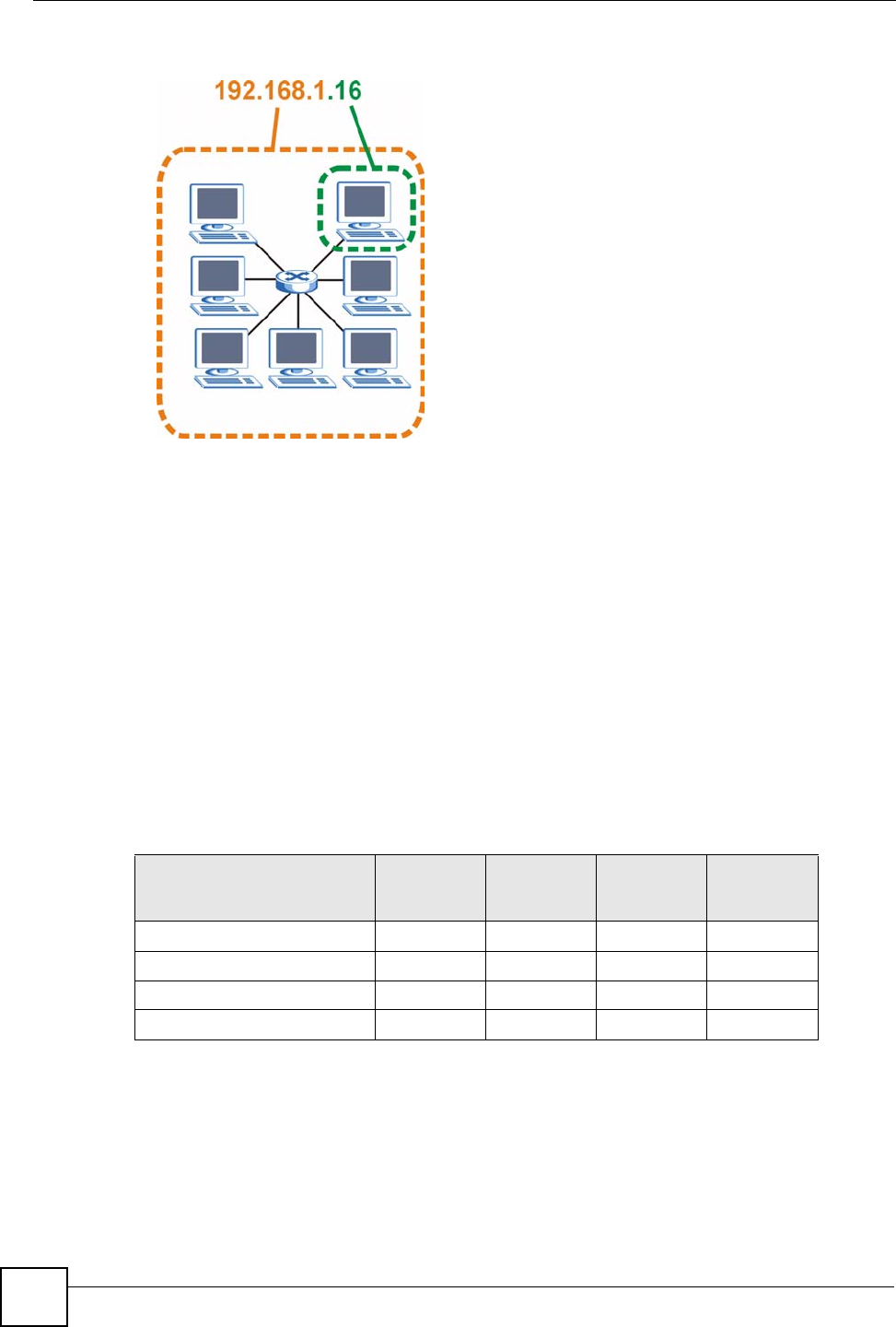
The following figure shows an example IP address in which the first three octets (192.168.1)
are the network number, and the fourth octet (16) is the host ID.
Appendix D IP Addresses and Subnetting
P-660HW-Dx v2 User’s Guide
302
Figure 185 Network Number and Host ID
How much of the IP address is the network number and how much is the host ID varies
according to the subnet mask.
Subnet Masks
A subnet mask is used to determine which bits are part of the network number, and which bits
are part of the host ID (using a logical AND operation). The term “subnet” is short for “sub-
network”.
A subnet mask has 32 bits. If a bit in the subnet mask is a “1” then the corresponding bit in the
IP address is part of the network number. If a bit in the subnet mask is “0” then the
corresponding bit in the IP address is part of the host ID.
The following example shows a subnet mask identifying the network number (in bold text)
and host ID of an IP address (192.168.1.2 in decimal).
By convention, subnet masks always consist of a continuous sequence of ones beginning from
the leftmost bit of the mask, followed by a continuous sequence of zeros, for a total number of
32 bits.
Subnet masks can be referred to by the size of the network number part (the bits with a “1”
value). For example, an “8-bit mask” means that the first 8 bits of the mask are ones and the
remaining 24 bits are zeroes.
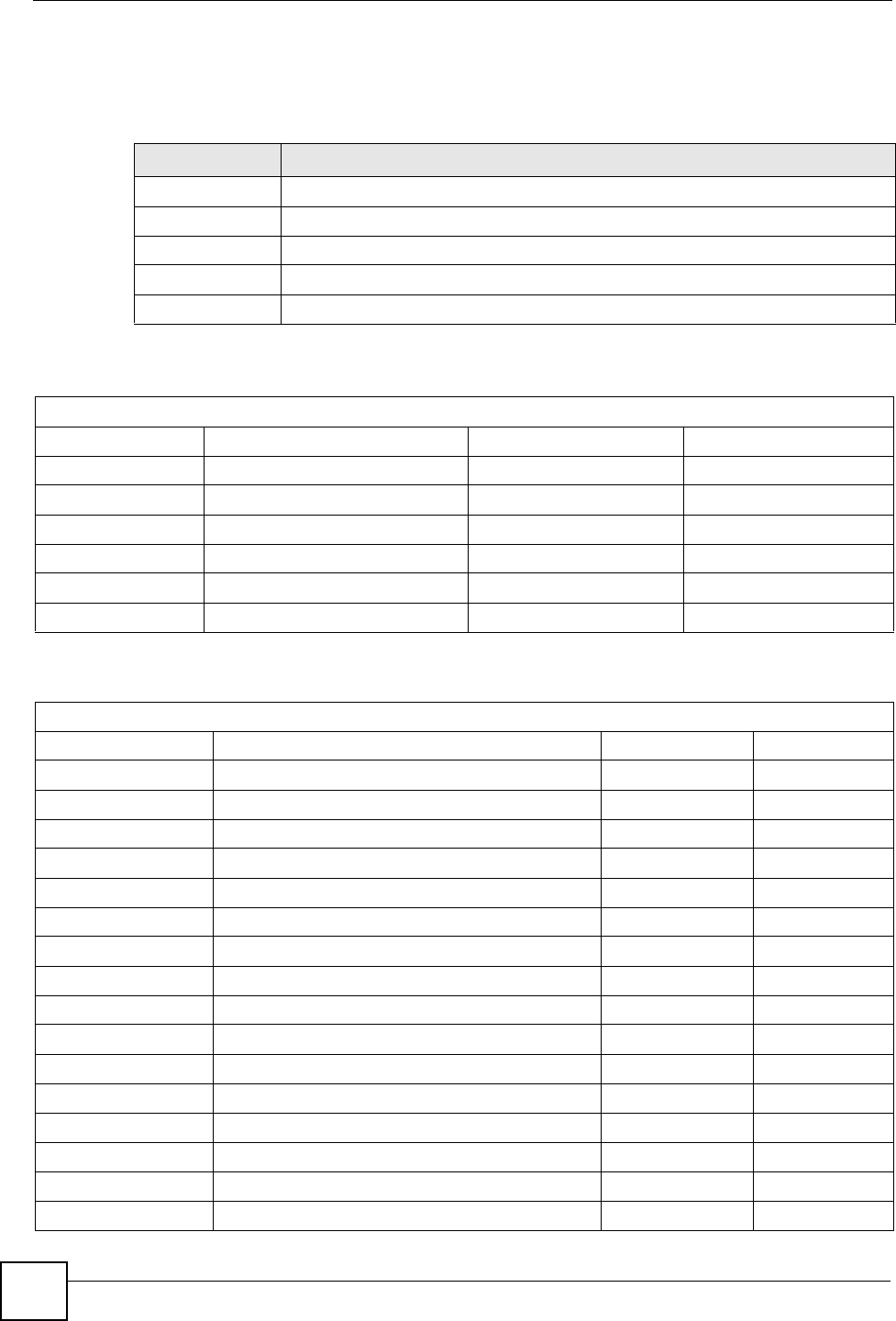
Table 125 IP Address Network Number and Host ID Example
1ST
OCTET:
(192)
2ND
OCTET:
(168)
3RD
OCTET:
(1)
4TH OCTET
(2)
IP Address (Binary) 11000000 10101000 00000001 00000010
Subnet Mask (Binary) 11111111 11111111 11111111 00000000
Network Number 11000000 10101000 00000001
Host ID 00000010
Appendix D IP Addresses and Subnetting
P-660HW-Dx v2 User’s Guide 303
Subnet masks are expressed in dotted decimal notation just like IP addresses. The following
examples show the binary and decimal notation for 8-bit, 16-bit, 24-bit and 29-bit subnet
masks.
Network Size
The size of the network number determines the maximum number of possible hosts you can
have on your network. The larger the number of network number bits, the smaller the number
of remaining host ID bits.
An IP address with host IDs of all zeros is the IP address of the network (192.168.1.0 with a
24-bit subnet mask, for example). An IP address with host IDs of all ones is the broadcast
address for that network (192.168.1.255 with a 24-bit subnet mask, for example).
As these two IP addresses cannot be used for individual hosts, calculate the maximum number
of possible hosts in a network as follows:
Notation
Since the mask is always a continuous number of ones beginning from the left, followed by a
continuous number of zeros for the remainder of the 32 bit mask, you can simply specify the
number of ones instead of writing the value of each octet. This is usually specified by writing
a “/” followed by the number of bits in the mask after the address.
For example, 192.1.1.0 /25 is equivalent to saying 192.1.1.0 with subnet mask
255.255.255.128.
The following table shows some possible subnet masks using both notations.
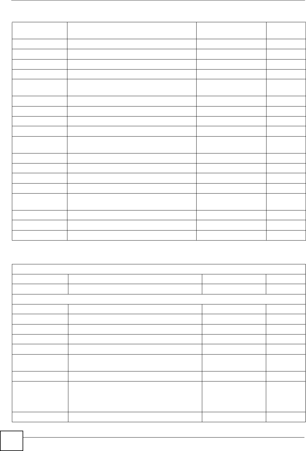
Table 126 Subnet Masks
BINARY
DECIMAL
1ST
OCTET
2ND
OCTET
3RD
OCTET 4TH OCTET
8-bit mask 11111111 00000000 00000000 00000000 255.0.0.0
16-bit mask 11111111 11111111 00000000 00000000 255.255.0.0
24-bit mask 11111111 11111111 11111111 00000000 255.255.255.0
29-bit mask 11111111 11111111 11111111 11111000 255.255.255.248
Table 127 Maximum Host Numbers
SUBNET MASK HOST ID SIZE MAXIMUM NUMBER OF HOSTS
8 bits 255.0.0.0 24 bits 224 – 2 16777214
16 bits 255.255.0.0 16 bits 216 – 2 65534
24 bits 255.255.255.0 8 bits 28 – 2 254
29 bits 255.255.255.248 3 bits 23 – 2 6
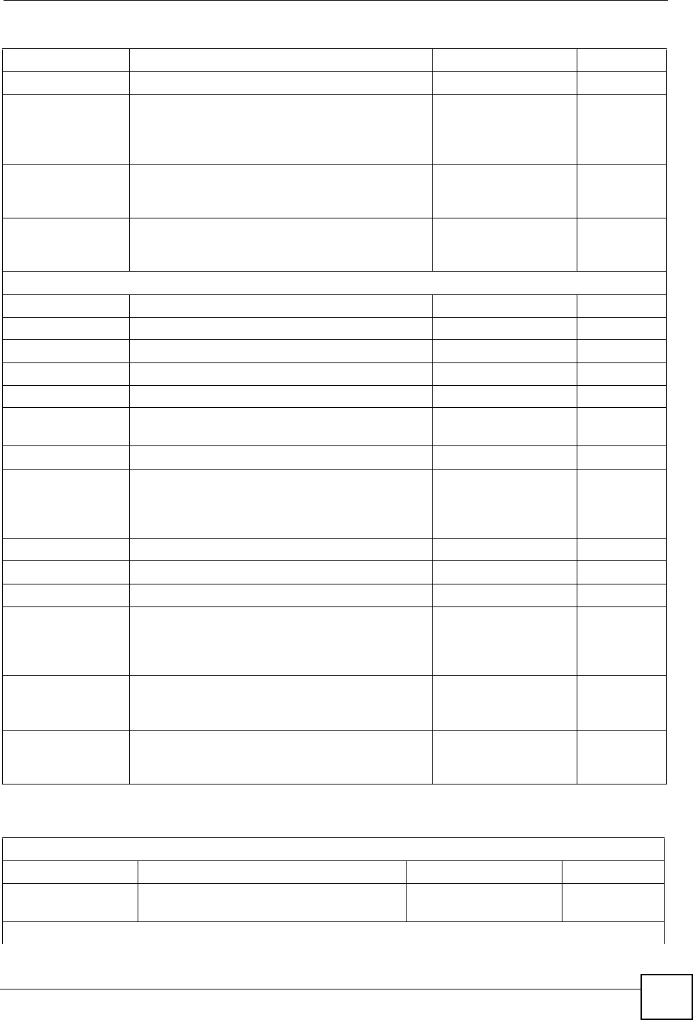
Table 128 Alternative Subnet Mask Notation
SUBNET MASK ALTERNATIVE
NOTATION
LAST OCTET
(BINARY)
LAST OCTET
(DECIMAL)
255.255.255.0 /24 0000 0000 0
255.255.255.128 /25 1000 0000 128
Appendix D IP Addresses and Subnetting
P-660HW-Dx v2 User’s Guide
304
Subnetting
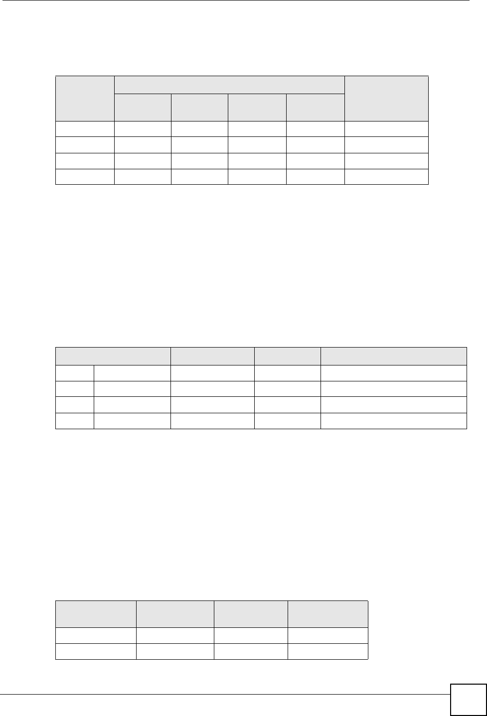
You can use subnetting to divide one network into multiple sub-networks. In the following
example a network administrator creates two sub-networks to isolate a group of servers from
the rest of the company network for security reasons.
In this example, the company network address is 192.168.1.0. The first three octets of the
address (192.168.1) are the network number, and the remaining octet is the host ID, allowing a
maximum of 28 – 2 or 254 possible hosts.
The following figure shows the company network before subnetting.
Figure 186 Subnetting Example: Before Subnetting
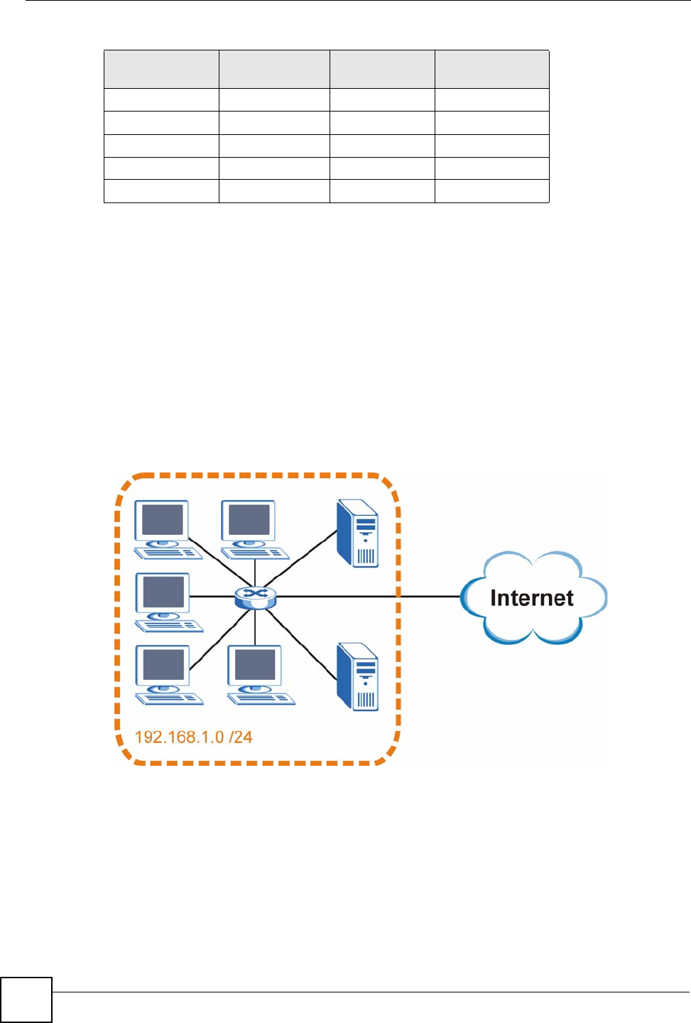
You can “borrow” one of the host ID bits to divide the network 192.168.1.0 into two separate
sub-networks. The subnet mask is now 25 bits (255.255.255.128 or /25).
The “borrowed” host ID bit can have a value of either 0 or 1, allowing two subnets;
192.168.1.0 /25 and 192.168.1.128 /25.
The following figure shows the company network after subnetting. There are now two sub-
networks, A and B.
255.255.255.192 /26 1100 0000 192
255.255.255.224 /27 1110 0000 224
255.255.255.240 /28 1111 0000 240
255.255.255.248 /29 1111 1000 248
255.255.255.252 /30 1111 1100 252
Table 128 Alternative Subnet Mask Notation (continued)
SUBNET MASK ALTERNATIVE
NOTATION
LAST OCTET
(BINARY)
LAST OCTET
(DECIMAL)
Appendix D IP Addresses and Subnetting
P-660HW-Dx v2 User’s Guide 305
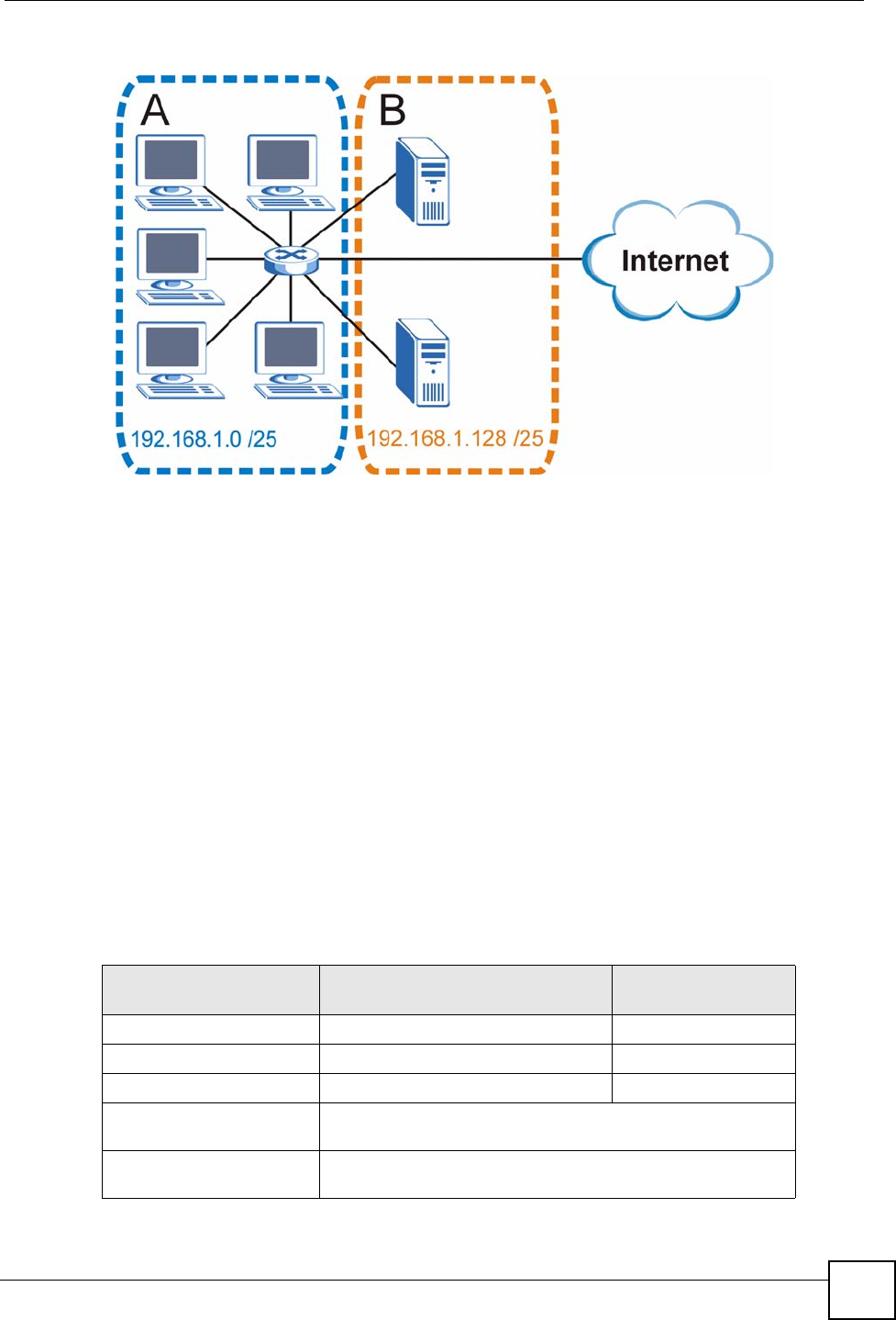
Figure 187 Subnetting Example: After Subnetting
In a 25-bit subnet the host ID has 7 bits, so each sub-network has a maximum of 27 – 2 or 126
possible hosts (a host ID of all zeroes is the subnet’s address itself, all ones is the subnet’s
broadcast address).
192.168.1.0 with mask 255.255.255.128 is subnet A itself, and 192.168.1.127 with mask
255.255.255.128 is its broadcast address. Therefore, the lowest IP address that can be assigned
to an actual host for subnet A is 192.168.1.1 and the highest is 192.168.1.126.
Similarly, the host ID range for subnet B is 192.168.1.129 to 192.168.1.254.
Example: Four Subnets
The previous example illustrated using a 25-bit subnet mask to divide a 24-bit address into two
subnets. Similarly, to divide a 24-bit address into four subnets, you need to “borrow” two host
ID bits to give four possible combinations (00, 01, 10 and 11). The subnet mask is 26 bits
(11111111.11111111.11111111.11000000) or 255.255.255.192.
Each subnet contains 6 host ID bits, giving 26 - 2 or 62 hosts for each subnet (a host ID of all
zeroes is the subnet itself, all ones is the subnet’s broadcast address).
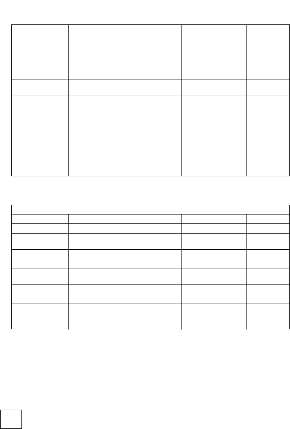
Table 129 Subnet 1
IP/SUBNET MASK NETWORK NUMBER LAST OCTET BIT
VALUE
IP Address (Decimal) 192.168.1. 0
IP Address (Binary) 11000000.10101000.00000001. 00000000
Subnet Mask (Binary) 11111111.11111111.11111111. 11000000
Subnet Address:
192.168.1.0
Lowest Host ID: 192.168.1.1
Broadcast Address:
192.168.1.63
Highest Host ID: 192.168.1.62
Appendix D IP Addresses and Subnetting
P-660HW-Dx v2 User’s Guide
306
Example: Eight Subnets
Similarly, use a 27-bit mask to create eight subnets (000, 001, 010, 011, 100, 101, 110 and
111).
The following table shows IP address last octet values for each subnet.
Table 130 Subnet 2
IP/SUBNET MASK NETWORK NUMBER LAST OCTET BIT
VALUE
IP Address 192.168.1. 64
IP Address (Binary) 11000000.10101000.00000001. 01000000
Subnet Mask (Binary) 11111111.11111111.11111111. 11000000
Subnet Address:
192.168.1.64
Lowest Host ID: 192.168.1.65
Broadcast Address:
192.168.1.127
Highest Host ID: 192.168.1.126
Table 131 Subnet 3
IP/SUBNET MASK NETWORK NUMBER LAST OCTET BIT
VALUE
IP Address 192.168.1. 128
IP Address (Binary) 11000000.10101000.00000001. 10000000
Subnet Mask (Binary) 11111111.11111111.11111111. 11000000
Subnet Address:
192.168.1.128
Lowest Host ID: 192.168.1.129
Broadcast Address:
192.168.1.191
Highest Host ID: 192.168.1.190
Table 132 Subnet 4
IP/SUBNET MASK NETWORK NUMBER LAST OCTET BIT
VALUE
IP Address 192.168.1. 192
IP Address (Binary) 11000000.10101000.00000001. 11000000
Subnet Mask (Binary) 11111111.11111111.11111111. 11000000
Subnet Address:
192.168.1.192
Lowest Host ID: 192.168.1.193
Broadcast Address:
192.168.1.255
Highest Host ID: 192.168.1.254
Table 133 Eight Subnets
SUBNET SUBNET
ADDRESS FIRST ADDRESS LAST
ADDRESS
BROADCAST
ADDRESS
1 0 1 30 31
232 33 62 63
364 65 94 95
496 97 126 127
Appendix D IP Addresses and Subnetting
P-660HW-Dx v2 User’s Guide 307
Subnet Planning
The following table is a summary for subnet planning on a network with a 24-bit network
number.
The following table is a summary for subnet planning on a network with a 16-bit network
number.
5128 129 158 159
6160 161 190 191
7192 193 222 223
8224 225 254 255
Table 133 Eight Subnets (continued)
SUBNET SUBNET
ADDRESS FIRST ADDRESS LAST
ADDRESS
BROADCAST
ADDRESS
Table 134 24-bit Network Number Subnet Planning
NO. “BORROWED”
HOST BITS SUBNET MASK NO. SUBNETS NO. HOSTS PER
SUBNET
1255.255.255.128 (/25) 2126
2255.255.255.192 (/26) 462
3255.255.255.224 (/27) 830
4255.255.255.240 (/28) 16 14
5255.255.255.248 (/29) 32 6
6255.255.255.252 (/30) 64 2
7255.255.255.254 (/31) 128 1
Table 135 16-bit Network Number Subnet Planning
NO. “BORROWED”
HOST BITS SUBNET MASK NO. SUBNETS NO. HOSTS PER
SUBNET
1255.255.128.0 (/17) 232766
2255.255.192.0 (/18) 416382
3255.255.224.0 (/19) 88190
4255.255.240.0 (/20) 16 4094
5255.255.248.0 (/21) 32 2046
6255.255.252.0 (/22) 64 1022
7255.255.254.0 (/23) 128 510
8255.255.255.0 (/24) 256 254
9255.255.255.128 (/25) 512 126
10 255.255.255.192 (/26) 1024 62
11 255.255.255.224 (/27) 2048 30
12 255.255.255.240 (/28) 4096 14
13 255.255.255.248 (/29) 8192 6
Appendix D IP Addresses and Subnetting
P-660HW-Dx v2 User’s Guide
308
Configuring IP Addresses
Where you obtain your network number depends on your particular situation. If the ISP or
your network administrator assigns you a block of registered IP addresses, follow their
instructions in selecting the IP addresses and the subnet mask.
If the ISP did not explicitly give you an IP network number, then most likely you have a single
user account and the ISP will assign you a dynamic IP address when the connection is
established. If this is the case, it is recommended that you select a network number from
192.168.0.0 to 192.168.255.0. The Internet Assigned Number Authority (IANA) reserved this
block of addresses specifically for private use; please do not use any other number unless you
are told otherwise. You must also enable Network Address Translation (NAT) on the ZyXEL
Device.
Once you have decided on the network number, pick an IP address for your ZyXEL Device
that is easy to remember (for instance, 192.168.1.1) but make sure that no other device on your
network is using that IP address.
The subnet mask specifies the network number portion of an IP address. Your ZyXEL Device
will compute the subnet mask automatically based on the IP address that you entered. You
don't need to change the subnet mask computed by the ZyXEL Device unless you are
instructed to do otherwise.
Private IP Addresses
Every machine on the Internet must have a unique address. If your networks are isolated from
the Internet (running only between two branch offices, for example) you can assign any IP
addresses to the hosts without problems. However, the Internet Assigned Numbers Authority
(IANA) has reserved the following three blocks of IP addresses specifically for private
networks:
• 10.0.0.0 — 10.255.255.255
• 172.16.0.0 — 172.31.255.255
• 192.168.0.0 — 192.168.255.255
You can obtain your IP address from the IANA, from an ISP, or it can be assigned from a
private network. If you belong to a small organization and your Internet access is through an
ISP, the ISP can provide you with the Internet addresses for your local networks. On the other
hand, if you are part of a much larger organization, you should consult your network
administrator for the appropriate IP addresses.
Regardless of your particular situation, do not create an arbitrary IP address; always follow the
guidelines above. For more information on address assignment, please refer to RFC 1597,
Address Allocation for Private Internets and RFC 1466, Guidelines for Management of IP
Address Space.
14 255.255.255.252 (/30) 16384 2
15 255.255.255.254 (/31) 32768 1
Table 135 16-bit Network Number Subnet Planning (continued)
NO. “BORROWED”
HOST BITS SUBNET MASK NO. SUBNETS NO. HOSTS PER
SUBNET
Appendix D IP Addresses and Subnetting
P-660HW-Dx v2 User’s Guide 309
IP Address Conflicts
Each device on a network must have a unique IP address. Devices with duplicate IP addresses
on the same network will not be able to access the Internet or other resources. The devices may
also be unreachable through the network.
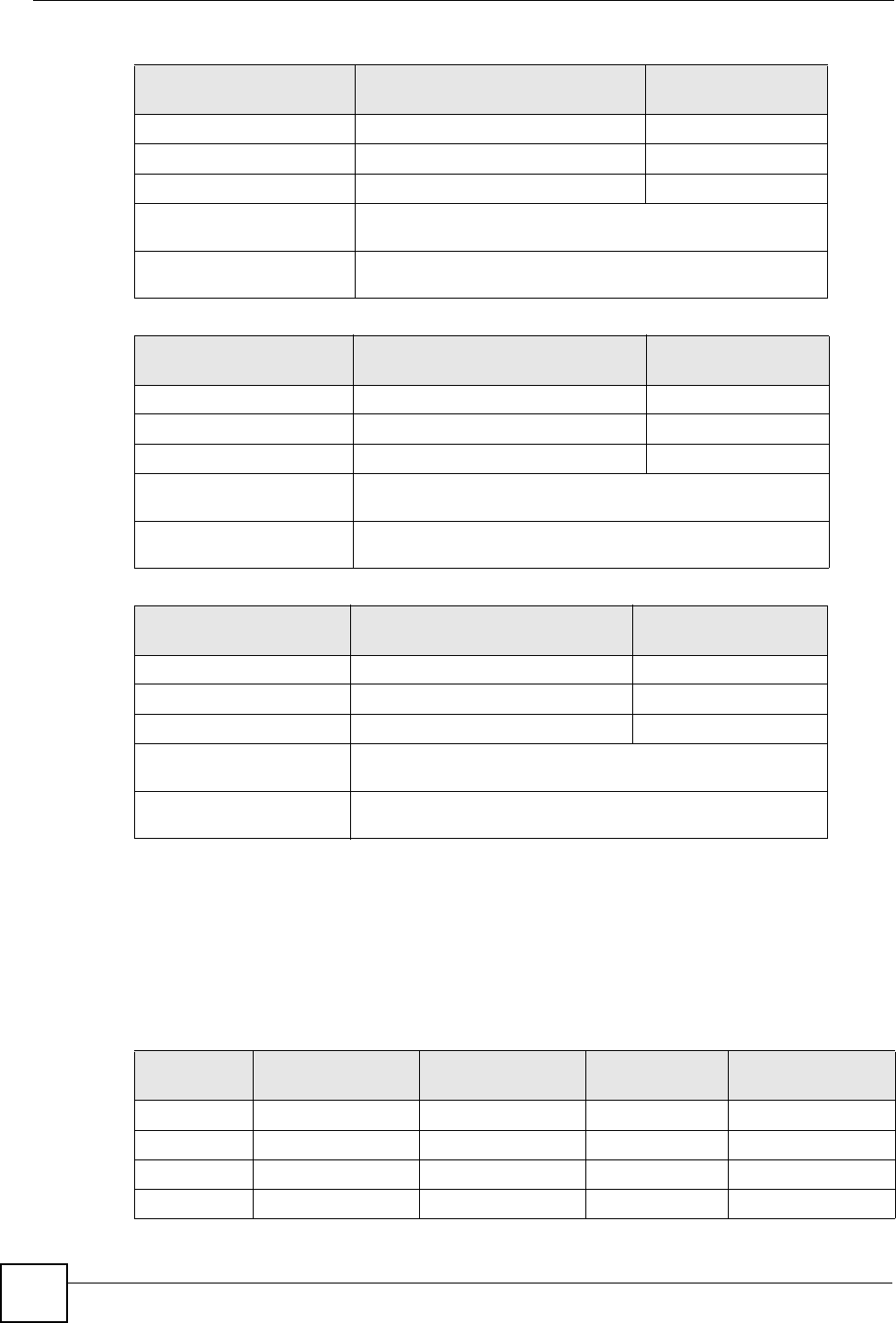
Conflicting Computer IP Addresses Example
More than one device can not use the same IP address. In the following example computer A
has a static (or fixed) IP address that is the same as the IP address that a DHCP server assigns
to computer B which is a DHCP client. Neither can access the Internet. This problem can be
solved by assigning a different static IP address to computer A or setting computer A to obtain
an IP address automatically.
Figure 188 Conflicting Computer IP Addresses Example
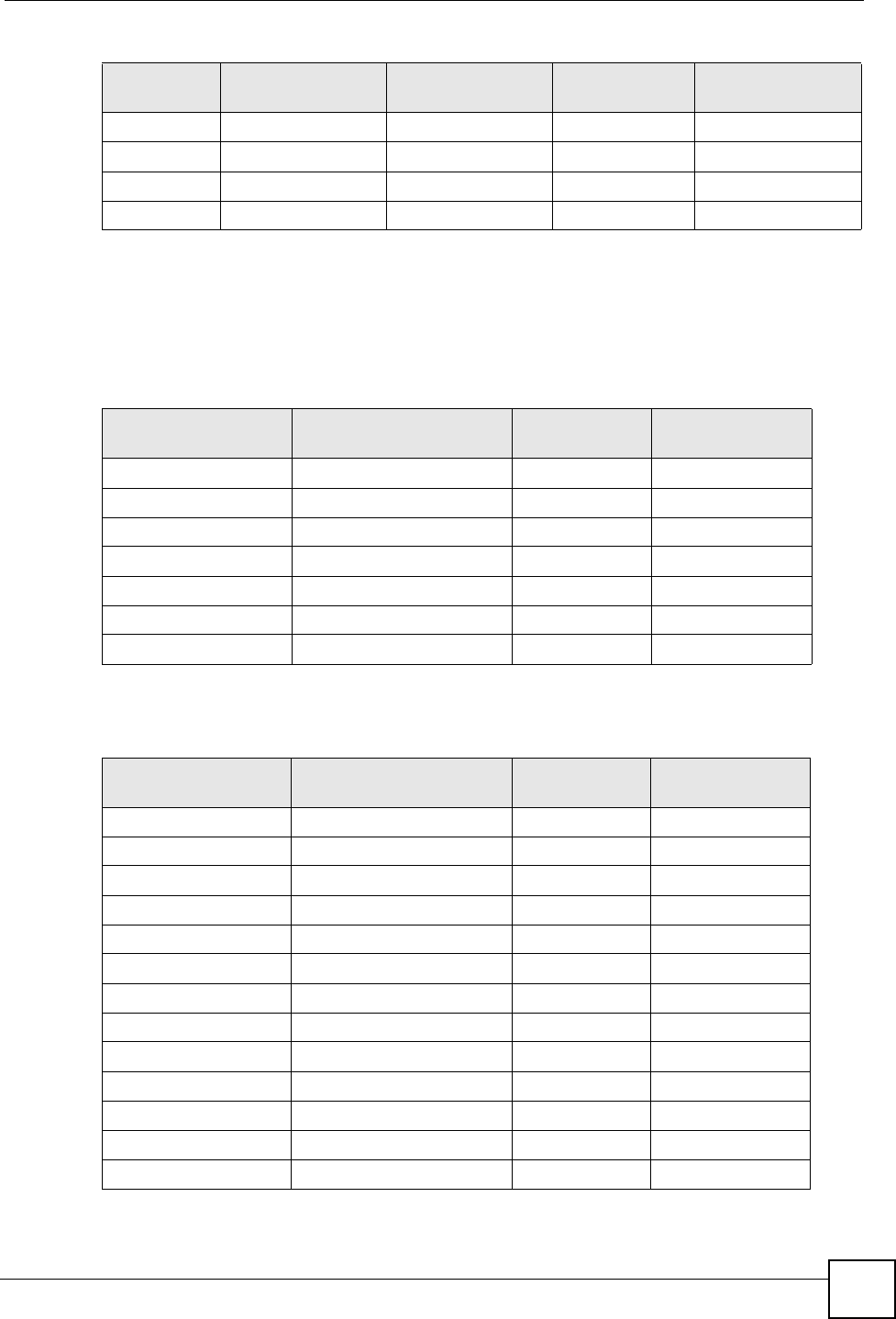
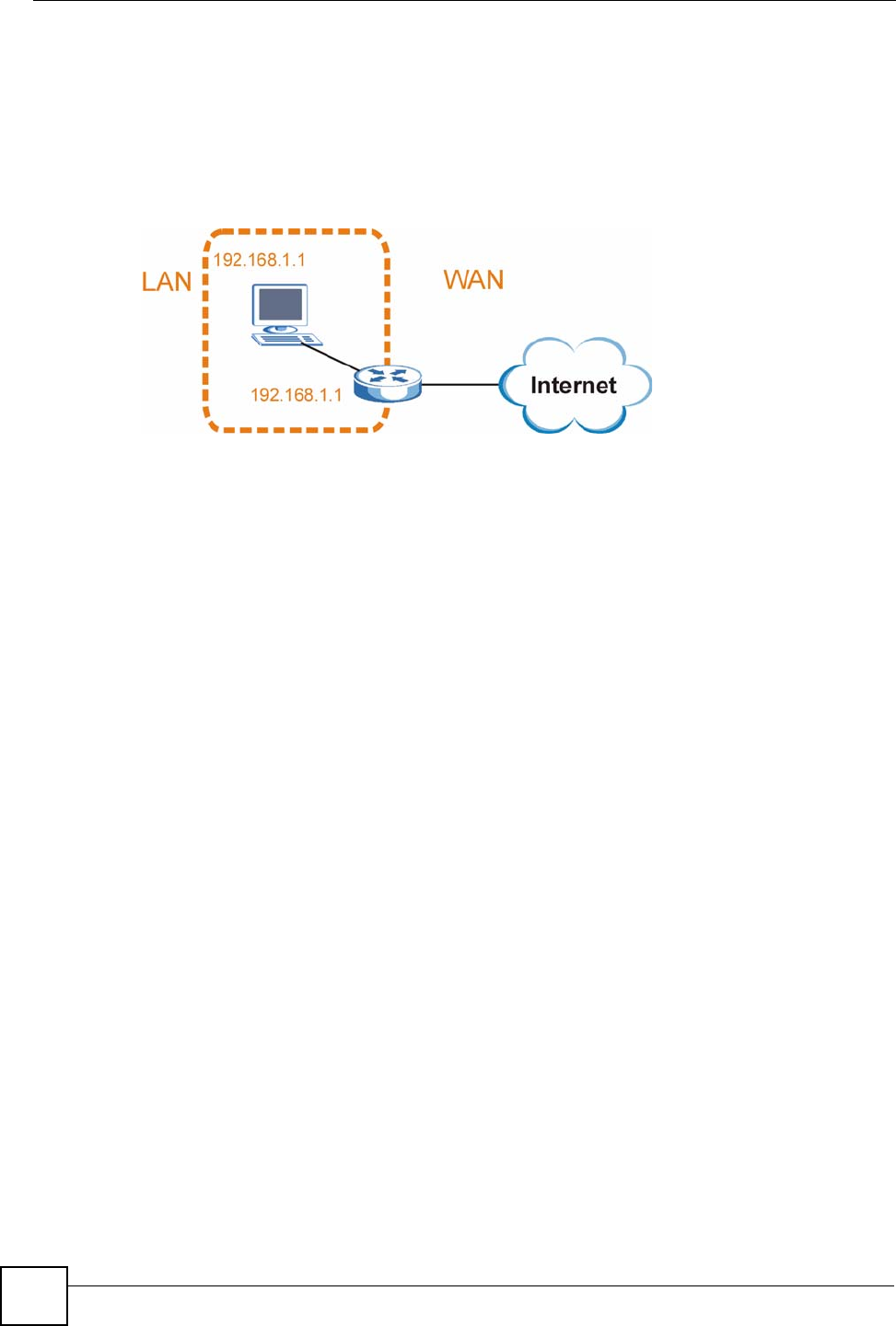
Conflicting Router IP Addresses Example
Since a router connects different networks, it must have interfaces using different network
numbers. For example, if a router is set between a LAN and the Internet (WAN), the router’s
LAN and WAN addresses must be on different subnets. In the following example, the LAN
and WAN are on the same subnet. The LAN computers cannot access the Internet because the
router cannot route between networks.
Figure 189 Conflicting Computer IP Addresses Example
Appendix D IP Addresses and Subnetting
P-660HW-Dx v2 User’s Guide
310
Conflicting Computer and Router IP Addresses Example
More than one device can not use the same IP address. In the following example, the computer
and the router’s LAN port both use 192.168.1.1 as the IP address. The computer cannot access
the Internet. This problem can be solved by assigning a different IP address to the computer or
the router’s LAN port.
Figure 190 Conflicting Computer and Router IP Addresses Example
P-660HW-Dx v2 User’s Guide 311
APPENDIX E
Firewall Commands
The following describes the firewall commands.
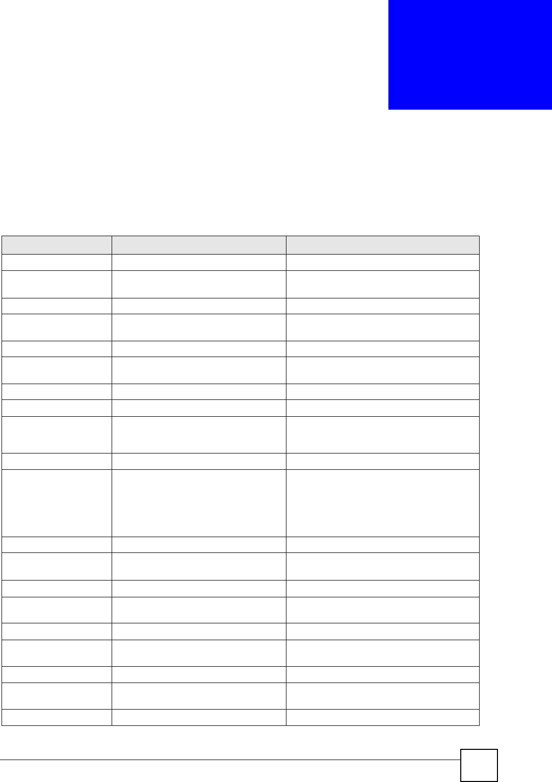
Table 136 Firewall Commands
FUNCTION COMMAND DESCRIPTION
Firewall SetUp
config edit firewall active
<yes | no>
This command turns the firewall on or off.
config retrieve firewall This command returns the previously saved
firewall settings.
config save firewall This command saves the current firewall
settings.
Display
config display firewall This command shows the of all the firewall
settings including e-mail, attack, and the sets/
rules.
config display firewall set
<set #>
This command shows the current
configuration of a set; including timeout
values, name, default-permit, and etc.If you
don’t put use a number (#) after “set”,
information about all of the sets/rules
appears.
config display firewall set
<set #> rule <rule #>
This command shows the current entries of a
rule in a firewall rule set.
config display firewall attack This command shows all of the attack
response settings.
config display firewall e-mail This command shows all of the e-mail
settings.
config display firewall? This command shows all of the available
firewall sub commands.

Appendix E Firewall Commands
P-660HW-Dx v2 User’s Guide
312
Edit
E-mail config edit firewall e-mail
mail-server <ip address of
mail server>
This command sets the IP address to which
the e-mail messages are sent.
config edit firewall e-mail
return-addr <e-mail address>
This command sets the source e-mail
address of the firewall e-mails.
config edit firewall e-mail
email-to <e-mail address>
This command sets the e-mail address to
which the firewall e-mails are sent.
config edit firewall e-mail
policy <full | hourly | daily
| weekly>
This command sets how frequently the
firewall log is sent via e-mail.
config edit firewall e-mail
day <sunday | monday | tuesday
| wednesday | thursday |
friday | saturday>
This command sets the day on which the
current firewall log is sent through e-mail if the
ZyXEL Device is set to send it on a weekly
basis.
config edit firewall e-mail
hour <0-23>
This command sets the hour when the firewall
log is sent through e- mail if the ZyXEL
Device is set to send it on an hourly, daily or
weekly basis.
config edit firewall e-mail
minute <0-59>
This command sets the minute of the hour for
the firewall log to be sent via e- mail if the
ZyXEL Device is set to send it on a hourly,
daily or weekly basis.
Attack config edit firewall attack
send-alert <yes | no>
This command enables or disables the
immediate sending of DOS attack notification
e-mail messages.
config edit firewall attack
block <yes | no>
Set this command to yes to block new traffic
after the tcp-max-incomplete threshold is
exceeded. Set it to no to delete the oldest
half-open session when traffic exceeds the
tcp-max-incomplete threshold.
config edit firewall attack
block-minute <0-255>
This command sets the number of minutes for
new sessions to be blocked when the tcp-
max-incomplete threshold is reached. This
command is only valid when block is set to
yes.
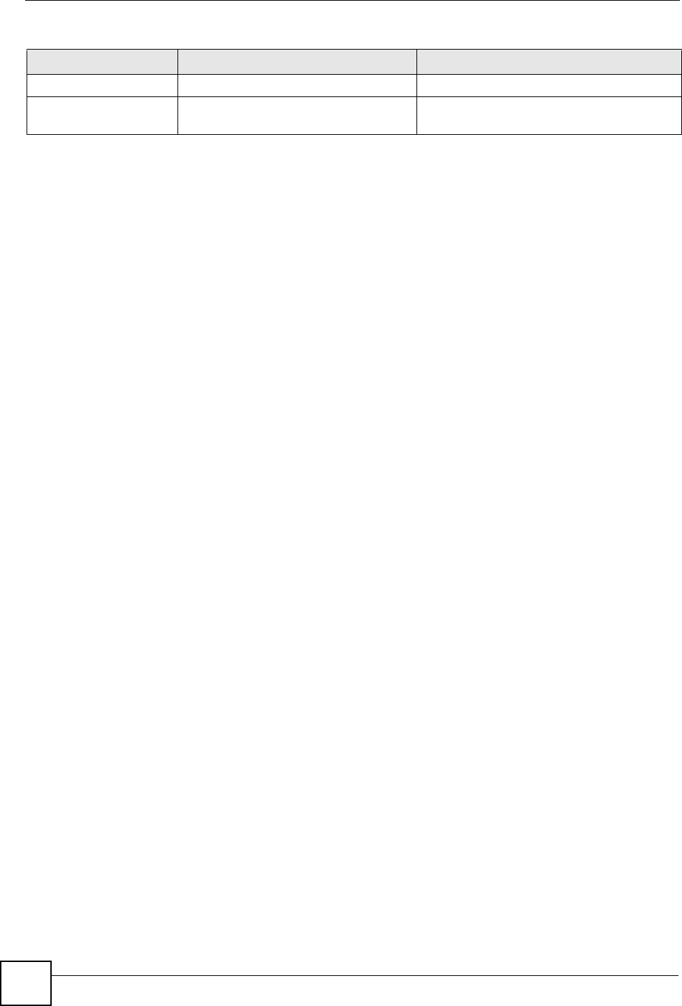
Table 136 Firewall Commands (continued)
FUNCTION COMMAND DESCRIPTION

Appendix E Firewall Commands
P-660HW-Dx v2 User’s Guide 313
config edit firewall attack
minute-high <0-255>
This command sets the threshold rate of new
half-open sessions per minute where the
ZyXEL Device starts deleting old half-opened
sessions until it gets them down to the
minute-low threshold.
config edit firewall attack
minute-low <0-255>
This command sets the threshold of half-open
sessions where the ZyXEL Device stops
deleting half-opened sessions.
config edit firewall attack
max-incomplete-high <0-255>
This command sets the threshold of half-open
sessions where the ZyXEL Device starts
deleting old half-opened sessions until it gets
them down to the max incomplete low.
config edit firewall attack
max-incomplete-low <0-255>
This command sets the threshold where the
ZyXEL Device stops deleting half-opened
sessions.
config edit firewall attack
tcp-max-incomplete <0-255>
This command sets the threshold of half-open
TCP sessions with the same destination
where the ZyXEL Device starts dropping half-
open sessions to that destination.
Sets config edit firewall set <set
#> name <desired name>
This command sets a name to identify a
specified set.
Config edit firewall set <set
#> default-permit <forward |
block>
This command sets whether a packet is
dropped or allowed through, when it does not
meet a rule within the set.
Config edit firewall set <set
#> icmp-timeout <seconds>
This command sets the time period to allow
an ICMP session to wait for the ICMP
response.
Config edit firewall set <set
#> udp-idle-timeout <seconds>
This command sets how long a UDP
connection is allowed to remain inactive
before the ZyXEL Device considers the
connection closed.
Config edit firewall set <set
#> connection-timeout
<seconds>
This command sets how long ZyXEL Device
waits for a TCP session to be established
before dropping the session.
Config edit firewall set <set
#> fin-wait-timeout <seconds>
This command sets how long the ZyXEL
Device leaves a TCP session open after the
firewall detects a FIN-exchange (indicating
the end of the TCP session).
Table 136 Firewall Commands (continued)
FUNCTION COMMAND DESCRIPTION

Appendix E Firewall Commands
P-660HW-Dx v2 User’s Guide
314
Config edit firewall set <set
#> tcp-idle-timeout <seconds>
This command sets how long ZyXEL Device
lets an inactive TCP connection remain open
before considering it closed.
Config edit firewall set <set
#> log <yes | no>
This command sets whether or not the ZyXEL
Device creates logs for packets that match
the firewall’s default rule set.
Rules Config edit firewall set <set
#> rule <rule #> permit
<forward | block>
This command sets whether packets that
match this rule are dropped or allowed
through.
Config edit firewall set <set
#> rule <rule #> active <yes |
no>
This command sets whether a rule is enabled
or not.
Config edit firewall set <set
#> rule <rule #> protocol
<integer protocol value >
This command sets the protocol specification
number made in this rule for ICMP.
Config edit firewall set <set
#> rule <rule #> log <none |
match | not-match | both>
This command sets the ZyXEL Device to log
traffic that matches the rule, doesn't match,
both or neither.
Config edit firewall set <set
#> rule <rule #> alert <yes |
no>
This command sets whether or not the ZyXEL
Device sends an alert e-mail when a DOS
attack or a violation of a particular rule occurs.
config edit firewall set <set
#> rule <rule #> srcaddr-
single <ip address>
This command sets the rule to have the
ZyXEL Device check for traffic with this
individual source address.
config edit firewall set <set
#> rule <rule #> srcaddr-
subnet <ip address> <subnet
mask>
This command sets a rule to have the ZyXEL
Device check for traffic from a particular
subnet (defined by IP address and subnet
mask).
config edit firewall set <set
#> rule <rule #> srcaddr-range
<start ip address> <end ip
address>
This command sets a rule to have the ZyXEL
Device check for traffic from this range of
addresses.
Table 136 Firewall Commands (continued)
FUNCTION COMMAND DESCRIPTION

Appendix E Firewall Commands
P-660HW-Dx v2 User’s Guide 315
config edit firewall set <set
#> rule <rule #> destaddr-
single <ip address>
This command sets the rule to have the
ZyXEL Device check for traffic with this
individual destination address.
config edit firewall set <set
#> rule <rule #> destaddr-
subnet <ip address> <subnet
mask>
This command sets a rule to have the ZyXEL
Device check for traffic with a particular
subnet destination (defined by IP address and
subnet mask).
config edit firewall set <set
#> rule <rule #> destaddr-
range <start ip address> <end
ip address>
This command sets a rule to have the ZyXEL
Device check for traffic going to this range of
addresses.
config edit firewall set <set
#> rule <rule #> TCP destport-
single <port #>
This command sets a rule to have the ZyXEL
Device check for TCP traffic with this
destination address. You may repeat this
command to enter various, non-consecutive
port numbers.
config edit firewall set <set
#> rule <rule #> TCP destport-
range <start port #> <end port
#>
This command sets a rule to have the ZyXEL
Device check for TCP traffic with a destination
port in this range.
config edit firewall set <set
#> rule <rule #> UDP destport-
single <port #>
This command sets a rule to have the ZyXEL
Device check for UDP traffic with this
destination address. You may repeat this
command to enter various, non-consecutive
port numbers.
config edit firewall set <set
#> rule <rule #> UDP destport-
range <start port #> <end port
#>
This command sets a rule to have the ZyXEL
Device check for UDP traffic with a
destination port in this range.
Delete
config delete firewall e-mail This command removes all of the settings for
e-mail alert.
config delete firewall attack This command resets all of the attack
response settings to their defaults.
config delete firewall set
<set #>
This command removes the specified set
from the firewall configuration.
Table 136 Firewall Commands (continued)
FUNCTION COMMAND DESCRIPTION
Appendix E Firewall Commands
P-660HW-Dx v2 User’s Guide
316
config delete firewall set
<set #> rule<rule #>
This command removes the specified rule in a
firewall configuration set.
Table 136 Firewall Commands (continued)
FUNCTION COMMAND DESCRIPTION

P-660HW-Dx v2 User’s Guide 317
APPENDIX F
Internal SPTGEN
This appendix introduces Internal SPTGEN. All menus shown in this appendix are example
menus meant to show SPTGEN usage. Actual menus for your product may differ.
Internal SPTGEN Overview
Internal SPTGEN (System Parameter Table Generator) is a configuration text file useful for
efficient configuration of multiple ZyXEL Devices. Internal SPTGEN lets you configure, save
and upload multiple menus at the same time using just one configuration text file – eliminating
the need to navigate and configure individual screens for each ZyXEL Device. You can use
FTP to get the Internal SPTGEN file. Then edit the file in a text editor and use FTP to upload
it again to the same device or another one. See the following sections for details.
The Configuration Text File Format
All Internal SPTGEN text files conform to the following format:
<field identification number = field name = parameter values allowed =
input>,
where <input> is your input conforming to <parameter values allowed>.
The figure shown next is an example of an Internal SPTGEN text file.
Figure 191 Configuration Text File Format: Column Descriptions
/ Menu 1 General Setup
10000000 = Configured <0(No)| 1(Yes)> = 1
10000001 = System Name <Str> = Your Device
10000002 = Location <Str> =
10000003 = Contact Person’s Name <Str> =
10000004 = Route IP <0(No)| 1(Yes)> = 1
10000005 = Route IPX <0(No)| 1(Yes)> = 0
10000006 = Bridge <0(No)| 1(Yes)> = 0
Appendix F Internal SPTGEN
P-660HW-Dx v2 User’s Guide
318
"DO NOT alter or delete any field except parameters in the Input column.
This appendix introduces Internal SPTGEN. All menus shown in this appendix are example
menus meant to show SPTGEN usage. Actual menus for your product may differ.
Internal SPTGEN File Modification - Important Points to Remember
Each parameter you enter must be preceded by one “=”sign and one space.
Some parameters are dependent on others. For example, if you disable the Configured field in
menu 1 (see Figure 191 on page 317), then you disable every field in this menu.
If you enter a parameter that is invalid in the Input column, the ZyXEL Device will not save
the configuration and the command line will display the Field Identification Number. Figure
192 on page 318, shown next, is an example of what the ZyXEL Device displays if you enter a
value other than “0” or “1” in the Input column of Field Identification Number 1000000
(refer to Figure 191 on page 317).
Figure 192 Invalid Parameter Entered: Command Line Example
The ZyXEL Device will display the following if you enter parameter(s) that are valid.
Figure 193 Valid Parameter Entered: Command Line Example
Internal SPTGEN FTP Download Example
1Launch your FTP application.
2Enter "bin". The command “bin” sets the transfer mode to binary.
3Get "rom-t" file. The command “get” transfers files from the ZyXEL Device to your
computer. The name “rom-t” is the configuration filename on the ZyXEL Device.
4Edit the "rom-t" file using a text editor (do not use a word processor). You must leave
this FTP screen to edit.
field value is not legal error:-1
ROM-t is not saved, error Line ID:10000000
reboot to get the original configuration
Bootbase Version: V2.02 | 2/22/2001 13:33:11
RAM: Size = 8192 Kbytes
FLASH: Intel 8M *2
Please wait for the system to write SPT text file(ROM-t)...
Bootbase Version: V2.02 | 2/22/2001 13:33:11
RAM: Size = 8192 Kbytes
FLASH: Intel 8M *2

Appendix F Internal SPTGEN
P-660HW-Dx v2 User’s Guide 319
Figure 194 Internal SPTGEN FTP Download Example
"You can rename your “rom-t” file when you save it to your computer but it must
be named “rom-t” when you upload it to your ZyXEL Device.
Internal SPTGEN FTP Upload Example
1Launch your FTP application.
2Enter "bin". The command “bin” sets the transfer mode to binary.
3Upload your “rom-t” file from your computer to the ZyXEL Device using the “put”
command. computer to the ZyXEL Device.
4Exit this FTP application.
Figure 195 Internal SPTGEN FTP Upload Example
c:\ftp 192.168.1.1
220 PPP FTP version 1.0 ready at Sat Jan 1 03:22:12 2000
User (192.168.1.1:(none)):
331 Enter PASS command
Password:
230 Logged in
ftp>bin
200 Type I OK
ftp> get rom-t
ftp>bye
c:\edit rom-t
(edit the rom-t text file by a text editor and save it)
c:\ftp 192.168.1.1
220 PPP FTP version 1.0 ready at Sat Jan 1 03:22:12 2000
User (192.168.1.1:(none)):
331 Enter PASS command
Password:
230 Logged in
ftp>bin
200 Type I OK
ftp> put rom-t
ftp>bye
Appendix F Internal SPTGEN
P-660HW-Dx v2 User’s Guide
320
Example Internal SPTGEN Menus
This section provides example Internal SPTGEN menus.
Table 137 Abbreviations Used in the Example Internal SPTGEN Screens Table
ABBREVIATION MEANING
FIN Field Identification Number
FN Field Name
PVA Parameter Values Allowed
INPUT An example of what you may enter
* Applies to the ZyXEL Device.
Table 138 Menu 1 General Setup
/ Menu 1 General Setup
FIN FN PVA INPUT
10000000 = Configured <0(No) | 1(Yes)> = 0
10000001 = System Name <Str> = Your Device
10000002 = Location <Str> =
10000003 = Contact Person's Name <Str> =
10000004 = Route IP <0(No) | 1(Yes)> = 1
10000006 = Bridge <0(No) | 1(Yes)> = 0
Table 139 Menu 3
/ Menu 3.1 General Ethernet Setup
FIN FN PVA INPUT
30100001 = Input Protocol filters Set 1 = 2
30100002 = Input Protocol filters Set 2 = 256
30100003 = Input Protocol filters Set 3 = 256
30100004 = Input Protocol filters Set 4 = 256
30100005 = Input device filters Set 1 = 256
30100006 = Input device filters Set 2 = 256
30100007 = Input device filters Set 3 = 256
30100008 = Input device filters Set 4 = 256
30100009 = Output protocol filters Set 1 = 256
30100010 = Output protocol filters Set 2 = 256
30100011 = Output protocol filters Set 3 = 256
30100012 = Output protocol filters Set 4 = 256
30100013 = Output device filters Set 1 = 256
30100014 = Output device filters Set 2 = 256
30100015 = Output device filters Set 3 = 256
30100016 = Output device filters Set 4 = 256

Appendix F Internal SPTGEN
P-660HW-Dx v2 User’s Guide 321
/ Menu 3.2 TCP/IP and DHCP Ethernet Setup
FIN FN PVA INPUT
30200001 = DHCP <0(None) |
1(Server) |
2(Relay)>
= 0
30200002 = Client IP Pool Starting Address =
192.168.1.33
30200003 = Size of Client IP Pool = 32
30200004 = Primary DNS Server = 0.0.0.0
30200005 = Secondary DNS Server = 0.0.0.0
30200006 = Remote DHCP Server = 0.0.0.0
30200008 = IP Address =
172.21.2.200
30200009 = IP Subnet Mask = 16
30200010 = RIP Direction <0(None) |
1(Both) | 2(In
Only) | 3(Out
Only)>
= 0
30200011 = Version <0(Rip-1) |
1(Rip-2B)
|2(Rip-2M)>
= 0
30200012 = Multicast <0(IGMP-v2) |
1(IGMP-v1) |
2(None)>
= 2
30200013 = IP Policies Set 1 (1~12) = 256
30200014 = IP Policies Set 2 (1~12) = 256
30200015 = IP Policies Set 3 (1~12) = 256
30200016 = IP Policies Set 4 (1~12) = 256
/ Menu 3.2.1 IP Alias Setup
FIN FN PVA INPUT
30201001 = IP Alias 1 <0(No) |
1(Yes)>
= 0
30201002 = IP Address = 0.0.0.0
30201003 = IP Subnet Mask = 0
30201004 = RIP Direction <0(None) |
1(Both) | 2(In
Only) | 3(Out
Only)>
= 0
30201005 = Version <0(Rip-1) |
1(Rip-2B)
|2(Rip-2M)>
= 0
30201006 = IP Alias #1 Incoming protocol filters
Set 1
= 256
30201007 = IP Alias #1 Incoming protocol filters
Set 2
= 256
Table 139 Menu 3

Appendix F Internal SPTGEN
P-660HW-Dx v2 User’s Guide
322
30201008 = IP Alias #1 Incoming protocol filters
Set 3
= 256
30201009 = IP Alias #1 Incoming protocol filters
Set 4
= 256
30201010 = IP Alias #1 Outgoing protocol filters
Set 1
= 256
30201011 = IP Alias #1 Outgoing protocol filters
Set 2
= 256
30201012 = IP Alias #1 Outgoing protocol filters
Set 3
= 256
30201013 = IP Alias #1 Outgoing protocol filters
Set 4
= 256
30201014 = IP Alias 2 <0(No) | 1(Yes)> = 0
30201015 = IP Address = 0.0.0.0
30201016 = IP Subnet Mask = 0
30201017 = RIP Direction <0(None) |
1(Both) | 2(In
Only) | 3(Out
Only)>
= 0
30201018 = Version <0(Rip-1) |
1(Rip-2B)
|2(Rip-2M)>
= 0
30201019 = IP Alias #2 Incoming protocol filters
Set 1
= 256
30201020 = IP Alias #2 Incoming protocol filters
Set 2
= 256
30201021 = IP Alias #2 Incoming protocol filters
Set 3
= 256
30201022 = IP Alias #2 Incoming protocol filters
Set 4
= 256
30201023 = IP Alias #2 Outgoing protocol filters
Set 1
= 256
30201024 = IP Alias #2 Outgoing protocol filters
Set 2
= 256
30201025 = IP Alias #2 Outgoing protocol filters
Set 3
= 256
30201026 = IP Alias #2 Outgoing protocol filters
Set 4
= 256
Table 139 Menu 3
Table 140 Menu 4 Internet Access Setup
/ Menu 4 Internet Access Setup
FIN FN PVA INPUT
40000000 = Configured <0(No) |
1(Yes)>
= 1

Appendix F Internal SPTGEN
P-660HW-Dx v2 User’s Guide 323
40000001 = ISP <0(No) |
1(Yes)>
= 1
40000002 = Active <0(No) |
1(Yes)>
= 1
40000003 = ISP's Name = ChangeMe
40000004 = Encapsulation <2(PPPOE) |
3(RFC 1483)|
4(PPPoA )|
5(ENET
ENCAP)>
= 2
40000005 = Multiplexing <1(LLC-based)
| 2(VC-based)
= 1
40000006 = VPI # = 0
40000007 = VCI # = 35
40000008 = Service Name <Str> = any
40000009 = My Login <Str> = test@pqa
40000010 = My Password <Str> = 1234
40000011 = Single User Account <0(No) |
1(Yes)>
= 1
40000012 = IP Address Assignment <0(Static)|1(
Dynamic)>
= 1
40000013 = IP Address = 0.0.0.0
40000014 = Remote IP address = 0.0.0.0
40000015 = Remote IP subnet mask = 0
40000016 = ISP incoming protocol filter set 1 = 6
40000017 = ISP incoming protocol filter set 2 = 256
40000018 = ISP incoming protocol filter set 3 = 256
40000019 = ISP incoming protocol filter set 4 = 256
40000020 = ISP outgoing protocol filter set 1 = 256
40000021 = ISP outgoing protocol filter set 2 = 256
40000022 = ISP outgoing protocol filter set 3 = 256
40000023 = ISP outgoing protocol filter set 4 = 256
40000024 = ISP PPPoE idle timeout = 0
40000025 = Route IP <0(No) |
1(Yes)>
= 1
40000026 = Bridge <0(No) |
1(Yes)>
= 0
40000027 = ATM QoS Type <0(CBR) | (1
(UBR)>
= 1
40000028 = Peak Cell Rate (PCR) = 0
40000029 = Sustain Cell Rate (SCR) = 0
40000030 = Maximum Burst Size(MBS) = 0
Table 140 Menu 4 Internet Access Setup (continued)

Appendix F Internal SPTGEN
P-660HW-Dx v2 User’s Guide
324
40000031= RIP Direction <0(None) |
1(Both) | 2(In
Only) | 3(Out
Only)>
= 0
40000032= RIP Version <0(Rip-1) |
1(Rip-2B)
|2(Rip-2M)>
= 0
40000033= Nailed-up Connection <0(No)
|1(Yes)>
= 0
Table 140 Menu 4 Internet Access Setup (continued)
Table 141 Menu 12
/ Menu 12.1.1 IP Static Route Setup
FIN FN PVA INPUT
120101001 = IP Static Route set #1, Name <Str> =
120101002 = IP Static Route set #1, Active <0(No) |1(Yes)> = 0
120101003 = IP Static Route set #1, Destination
IP address
= 0.0.0.0
120101004 = IP Static Route set #1, Destination
IP subnetmask
= 0
120101005 = IP Static Route set #1, Gateway = 0.0.0.0
120101006 = IP Static Route set #1, Metric = 0
120101007 = IP Static Route set #1, Private <0(No) |1(Yes)> = 0
/ Menu 12.1.2 IP Static Route Setup
FIN FN PVA INPUT
120108001 = IP Static Route set #8, Name <Str> =
120108002 = IP Static Route set #8, Active <0(No) |1(Yes)> = 0
120108003 = IP Static Route set #8, Destination
IP address
= 0.0.0.0
120108004 = IP Static Route set #8, Destination
IP subnetmask
= 0
120108005 = IP Static Route set #8, Gateway = 0.0.0.0
120108006 = IP Static Route set #8, Metric = 0
120108007 = IP Static Route set #8, Private <0(No) |1(Yes)> = 0
Table 142 Menu 15 SUA Server Setup
/ Menu 15 SUA Server Setup
FIN FN PVA INPUT
150000001 = SUA Server IP address for default
port
= 0.0.0.0
150000002 = SUA Server #2 Active <0(No) | 1(Yes)> = 0
150000003 = SUA Server #2 Protocol <0(All)|6(TCP)|17(U
DP)>
= 0

Appendix F Internal SPTGEN
P-660HW-Dx v2 User’s Guide 325
150000004 = SUA Server #2 Port Start = 0
150000005 = SUA Server #2 Port End = 0
150000006 = SUA Server #2 Local IP address = 0.0.0.0
150000007 = SUA Server #3 Active <0(No) | 1(Yes)> = 0
150000008 = SUA Server #3 Protocol <0(All)|6(TCP)|17(U
DP)>
= 0
150000009 = SUA Server #3 Port Start = 0
150000010 = SUA Server #3 Port End = 0
150000011 = SUA Server #3 Local IP address = 0.0.0.0
150000012 = SUA Server #4 Active <0(No) | 1(Yes)> = 0
150000013 = SUA Server #4 Protocol <0(All)|6(TCP)|17(U
DP)>
= 0
150000014 = SUA Server #4 Port Start = 0
150000015 = SUA Server #4 Port End = 0
150000016 = SUA Server #4 Local IP address = 0.0.0.0
150000017 = SUA Server #5 Active <0(No) | 1(Yes)> = 0
150000018 = SUA Server #5 Protocol <0(All)|6(TCP)|17(U
DP)>
= 0
150000019 = SUA Server #5 Port Start = 0
150000020 = SUA Server #5 Port End = 0
150000021 = SUA Server #5 Local IP address = 0.0.0.0
150000022 = SUA Server #6 Active <0(No) | 1(Yes)> =
0
= 0
150000023 = SUA Server #6 Protocol <0(All)|6(TCP)|17(U
DP)>
= 0
150000024 = SUA Server #6 Port Start = 0
150000025 = SUA Server #6 Port End = 0
150000026 = SUA Server #6 Local IP address = 0.0.0.0
150000027 = SUA Server #7 Active <0(No) | 1(Yes)> = 0
150000028 = SUA Server #7 Protocol <0(All)|6(TCP)|17(U
DP)>
= 0.0.0.0
150000029 = SUA Server #7 Port Start = 0
150000030 = SUA Server #7 Port End = 0
150000031 = SUA Server #7 Local IP address = 0.0.0.0
150000032 = SUA Server #8 Active <0(No) | 1(Yes)> = 0
150000033 = SUA Server #8 Protocol <0(All)|6(TCP)|17(U
DP)>
= 0
150000034 = SUA Server #8 Port Start = 0
150000035 = SUA Server #8 Port End = 0
150000036 = SUA Server #8 Local IP address = 0.0.0.0
150000037 = SUA Server #9 Active <0(No) | 1(Yes)> = 0
Table 142 Menu 15 SUA Server Setup (continued)
Appendix F Internal SPTGEN
P-660HW-Dx v2 User’s Guide
326
150000038 = SUA Server #9 Protocol <0(All)|6(TCP)|17(U
DP)>
= 0
150000039 = SUA Server #9 Port Start = 0
150000040 = SUA Server #9 Port End = 0
150000041 = SUA Server #9 Local IP address = 0.0.0.0
150000042 = SUA Server #10 Active <0(No) | 1(Yes)> = 0
150000043 = SUA Server #10 Protocol <0(All)|6(TCP)|17(U
DP)>
= 0
150000044 = SUA Server #10 Port Start = 0
150000045 = SUA Server #10 Port End = 0
150000046 = SUA Server #10 Local IP address = 0.0.0.0
150000047 = SUA Server #11 Active <0(No) | 1(Yes)> = 0
150000048 = SUA Server #11 Protocol <0(All)|6(TCP)|17(U
DP)>
= 0
150000049 = SUA Server #11 Port Start = 0
150000050 = SUA Server #11 Port End = 0
150000051 = SUA Server #11 Local IP address = 0.0.0.0
150000052 = SUA Server #12 Active <0(No) | 1(Yes)> = 0
150000053 = SUA Server #12 Protocol <0(All)|6(TCP)|17(U
DP)>
= 0
150000054 = SUA Server #12 Port Start = 0
150000055 = SUA Server #12 Port End = 0
150000056 = SUA Server #12 Local IP address = 0.0.0.0
Table 142 Menu 15 SUA Server Setup (continued)
Table 143 Menu 21.1 Filter Set #1
/ Menu 21 Filter set #1
FIN FN PVA INPUT
210100001 = Filter Set 1, Name <Str> =
/ Menu 21.1.1.1 set #1, rule #1
FIN FN PVA INPUT
210101001 = IP Filter Set 1,Rule 1 Type <2(TCP/IP)> = 2
210101002 = IP Filter Set 1,Rule 1 Active <0(No)|1(Yes)> = 1
210101003 = IP Filter Set 1,Rule 1 Protocol = 6
210101004 = IP Filter Set 1,Rule 1 Dest IP address = 0.0.0.0
210101005 = IP Filter Set 1,Rule 1 Dest Subnet
Mask
= 0
210101006 = IP Filter Set 1,Rule 1 Dest Port = 137
210101007 = IP Filter Set 1,Rule 1 Dest Port Comp <0(none)|1(equal)
|2(not equal)|
3(less)|
4(greater)>
= 1
210101008 = IP Filter Set 1,Rule 1 Src IP address = 0.0.0.0
Appendix F Internal SPTGEN
P-660HW-Dx v2 User’s Guide 327
210101009 = IP Filter Set 1,Rule 1 Src Subnet Mask = 0
210101010 = IP Filter Set 1,Rule 1 Src Port = 0
210101011 = IP Filter Set 1,Rule 1 Src Port Comp <0(none)|1(equal)
|2(not
equal)|3(less)|4(
greater)>
= 0
210101013 = IP Filter Set 1,Rule 1 Act Match <1(check
next)|2(forward)|
3(drop)>
= 3
210101014 = IP Filter Set 1,Rule 1 Act Not Match <1(check
next)|2(forward)|
3(drop)>
= 1
/ Menu 21.1.1.2 set #1, rule #2
FIN FN PVA INPUT
210102001 = IP Filter Set 1,Rule 2 Type <2(TCP/IP)> = 2
210102002 = IP Filter Set 1,Rule 2 Active <0(No)|1(Yes)> = 1
210102003 = IP Filter Set 1,Rule 2 Protocol = 6
210102004 = IP Filter Set 1,Rule 2 Dest IP address = 0.0.0.0
210102005 = IP Filter Set 1,Rule 2 Dest Subnet
Mask
= 0
210102006 = IP Filter Set 1,Rule 2 Dest Port = 138
210102007 = IP Filter Set 1,Rule 2 Dest Port Comp <0(none)|1(equal)
|2(not
equal)|3(less)|4(
greater)>
= 1
210102008 = IP Filter Set 1,Rule 2 Src IP address = 0.0.0.0
210102009 = IP Filter Set 1,Rule 2 Src Subnet Mask = 0
210102010 = IP Filter Set 1,Rule 2 Src Port = 0
210102011 = IP Filter Set 1,Rule 2 Src Port Comp <0(none)|1(equal)
|2(not
equal)|3(less)|4(
greater)>
= 0
210102013 = IP Filter Set 1,Rule 2 Act Match <1(check
next)|2(forward)|
3(drop)>
= 3
210102014 = IP Filter Set 1,Rule 2 Act Not Match <1(check
next)|2(forward)|
3(drop)>
= 1
Table 143 Menu 21.1 Filter Set #1 (continued)
Table 144 Menu 21.1 Filer Set #2,
/ Menu 21.1 filter set #2,
FIN FN PVA INPUT
210200001 = Filter Set 2, Nam <Str> =
NetBIOS_WAN
/ Menu 21.1.2.1 Filter set #2, rule #1

Appendix F Internal SPTGEN
P-660HW-Dx v2 User’s Guide
328
FIN FN PVA INPUT
210201001 = IP Filter Set 2, Rule 1 Type <0(none)|2(TCP/
IP)>
= 2
210201002 = IP Filter Set 2, Rule 1 Active <0(No)|1(Yes)> = 1
210201003 = IP Filter Set 2, Rule 1 Protocol = 6
210201004 = IP Filter Set 2, Rule 1 Dest IP
address
= 0.0.0.0
210201005 = IP Filter Set 2, Rule 1 Dest
Subnet Mask
= 0
210201006 = IP Filter Set 2, Rule 1 Dest Port = 137
210201007 = IP Filter Set 2, Rule 1 Dest Port
Comp
<0(none)|1(equal)|
2(not
equal)|3(less)|4(g
reater)>
= 1
210201008 = IP Filter Set 2, Rule 1 Src IP
address
= 0.0.0.0
210201009 = IP Filter Set 2, Rule 1 Src Subnet
Mask
= 0
210201010 = IP Filter Set 2, Rule 1 Src Port = 0
210201011 = IP Filter Set 2, Rule 1 Src Port
Comp
<0(none)|1(equal)|
2(not
equal)|3(less)|4(g
reater)>
= 0
210201013 = IP Filter Set 2, Rule 1 Act Match <1(check
next)|2(forward)|3
(drop)>
= 3
210201014 = IP Filter Set 2, Rule 1 Act Not
Match
<1(check
next)|2(forward)|3
(drop)>
= 1
/ Menu 21.1.2.2 Filter set #2, rule #2
FIN FN PVA INPUT
210202001 = IP Filter Set 2, Rule 2 Type <0(none)|2(TCP/
IP)>
= 2
210202002 = IP Filter Set 2, Rule 2 Active <0(No)|1(Yes)> = 1
210202003 = IP Filter Set 2, Rule 2 Protocol = 6
210202004 = IP Filter Set 2, Rule 2 Dest IP
address
= 0.0.0.0
210202005 = IP Filter Set 2, Rule 2 Dest
Subnet Mask
= 0
210202006 = IP Filter Set 2, Rule 2 Dest Port = 138
210202007 = IP Filter Set 2, Rule 2 Dest Port
Comp
<0(none)|1(equal)|
2(not
equal)|3(less)|4(g
reater)>
= 1
210202008 = IP Filter Set 2, Rule 2 Src IP
address
= 0.0.0.0
Table 144 Menu 21.1 Filer Set #2, (continued)

Appendix F Internal SPTGEN
P-660HW-Dx v2 User’s Guide 329
210202009 = IP Filter Set 2, Rule 2 Src Subnet
Mask
= 0
210202010 = IP Filter Set 2,Rule 2 Src Port = 0
210202011 = IP Filter Set 2, Rule 2 Src Port
Comp
<0(none)|1(equal)|
2(not
equal)|3(less)|4(g
reater)>
= 0
210202013 = IP Filter Set 2, Rule 2 Act Match <1(check
next)|2(forward)|3
(drop)>
= 3
210202014 = IP Filter Set 2, Rule 2 Act Not
Match
<1(check
next)|2(forward)|3
(drop)>
= 1
Table 144 Menu 21.1 Filer Set #2, (continued)
Table 145 Menu 23 System Menus
*/ Menu 23.1 System Password Setup
FIN FN PVA INPUT
230000000 = System Password = 1234
*/ Menu 23.2 System security: radius server
FIN FN PVA INPUT
230200001 = Authentication Server Configured <0(No) | 1(Yes)> = 1
230200002 = Authentication Server Active <0(No) | 1(Yes)> = 1
230200003 = Authentication Server IP Address =
192.168.1.32
230200004 = Authentication Server Port = 1822
230200005 = Authentication Server Shared
Secret
=
111111111111
111
111111111111
1111
230200006 = Accounting Server Configured <0(No) | 1(Yes)> = 1
230200007 = Accounting Server Active <0(No) | 1(Yes)> = 1
230200008 = Accounting Server IP Address =
192.168.1.44
230200009 = Accounting Server Port = 1823
230200010 = Accounting Server Shared Secret = 1234
*/ Menu 23.4 System security: IEEE802.1x
FIN FN PVA INPUT
230400001 = Wireless Port Control <0(Authentication
Required) |1(No
Access Allowed)
|2(No
Authentication
Required)>
= 2
Appendix F Internal SPTGEN
P-660HW-Dx v2 User’s Guide
330
230400002 = ReAuthentication Timer (in second) = 555
230400003 = Idle Timeout (in second) = 999
230400004 = Authentication Databases <0(Local User
Database Only)
|1(RADIUS Only)
|2(Local,RADIUS)
|3(RADIUS,Local)>
= 1
230400005 = Key Management Protocol <0(8021x) |1(WPA)
|2(WPAPSK)>
= 0
230400006 = Dynamic WEP Key Exchange <0(Disable) |1(64-
bit WEP) |2(128-bit
WEP)>
= 0
230400007 = PSK = =
230400008 = WPA Mixed Mode <0(Disable)
|1(Enable)>
= 0
230400009 = Data Privacy for Broadcast/
Multicast packets
<0(TKIP) |1(WEP)> = 0
230400010 = WPA Broadcast/Multicast Key Update
Timer
= 0
Table 145 Menu 23 System Menus (continued)
Table 146 Menu 24.11 Remote Management Control
/ Menu 24.11 Remote Management Control
FIN FN PVA INPUT
241100001 = TELNET Server Port = 23
241100002 = TELNET Server Access <0(all)|1(none)|2(
Lan)|3(Wan)>
= 0
241100003 = TELNET Server Secured IP address = 0.0.0.0
241100004 = FTP Server Port = 21
241100005 = FTP Server Access <0(all)|1(none)|2(
Lan)|3(Wan)>
= 0
241100006 = FTP Server Secured IP address = 0.0.0.0
241100007 = WEB Server Port = 80
241100008 = WEB Server Access <0(all)|1(none)|2(
Lan) |3(Wan)>
= 0
241100009 = WEB Server Secured IP address = 0.0.0.0
Appendix F Internal SPTGEN
P-660HW-Dx v2 User’s Guide 331
Command Examples
The following are example Internal SPTGEN screens associated with the ZyXEL Device’s
command interpreter commands.
Table 147 Command Examples
FIN FN PVA INPUT
/ci command (for annex a): wan adsl opencmd
FIN FN PVA INPUT
990000001 = ADSL OPMD <0(glite)|1(t1.413
)|2(gdmt)|3(multim
ode)>
= 3
/ci command (for annex B): wan adsl opencmd
FIN FN PVA INPUT
990000001 = ADSL OPMD <0(etsi)|1(normal)
|2(gdmt)|3(multimo
de)>
= 3

Appendix F Internal SPTGEN
P-660HW-Dx v2 User’s Guide
332
P-660HW-Dx v2 User’s Guide 333
APPENDIX G
Pop-up Windows, JavaScripts
and Java Permissions
In order to use the web configurator you need to allow:
• Web browser pop-up windows from your device.
• JavaScripts (enabled by default).
• Java permissions (enabled by default).
"Internet Explorer 6 screens are used here. Screens for other Internet Explorer
versions may vary.
Internet Explorer Pop-up Blockers
You may have to disable pop-up blocking to log into your device.
Either disable pop-up blocking (enabled by default in Windows XP SP (Service Pack) 2) or
allow pop-up blocking and create an exception for your device’s IP address.
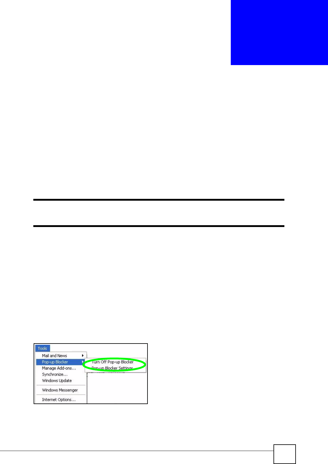
Disable pop-up Blockers
1In Internet Explorer, select Tools, Pop-up Blocker and then select Turn Off Pop-up
Blocker.
Figure 196 Pop-up Blocker
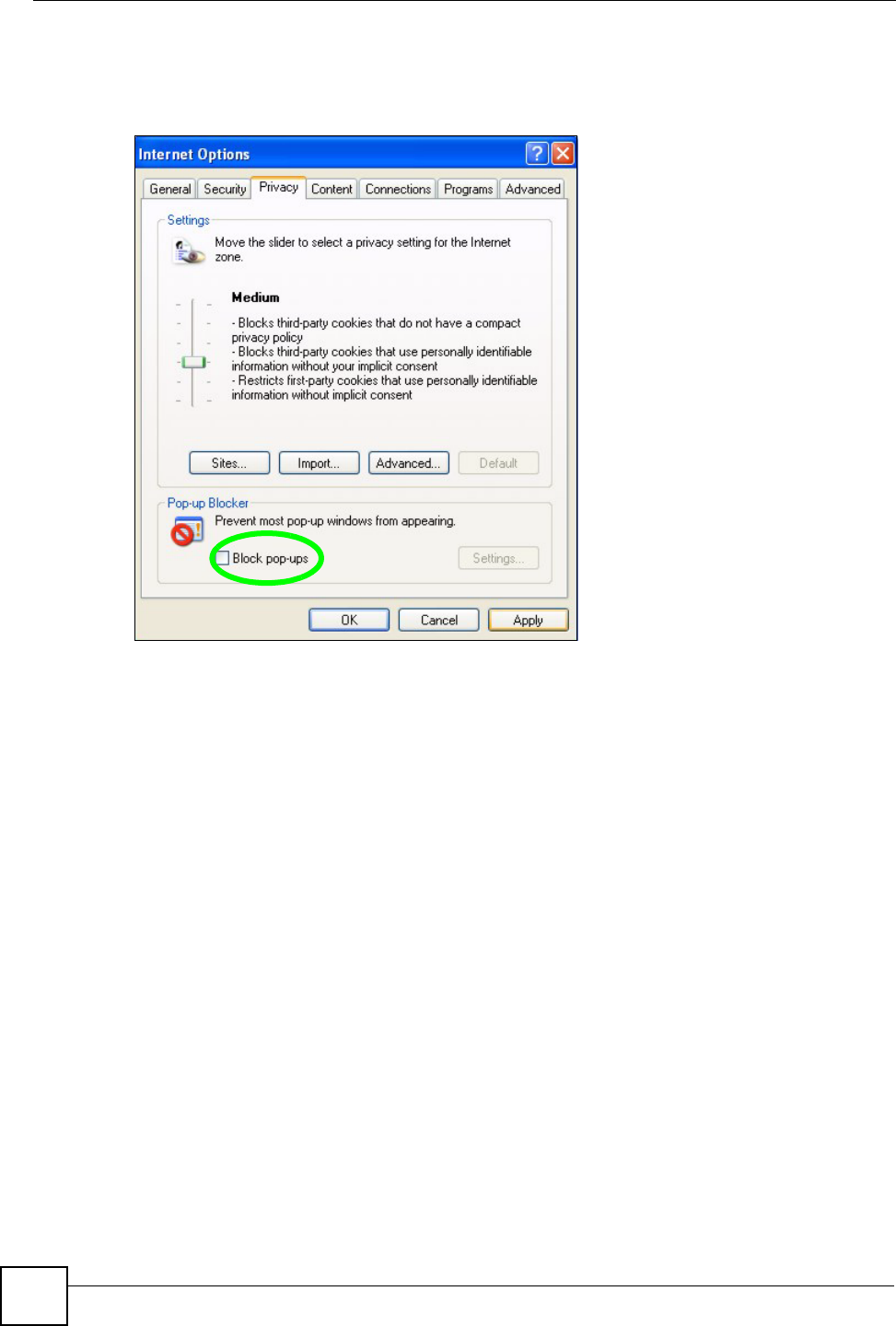
You can also check if pop-up blocking is disabled in the Pop-up Blocker section in the
Privacy tab.
1In Internet Explorer, select Tools, Internet Options, Privacy.
Appendix G Pop-up Windows, JavaScripts and Java Permissions
P-660HW-Dx v2 User’s Guide
334
2Clear the Block pop-ups check box in the Pop-up Blocker section of the screen. This
disables any web pop-up blockers you may have enabled.
Figure 197 Internet Options: Privacy
3Click Apply to save this setting.
Enable pop-up Blockers with Exceptions
Alternatively, if you only want to allow pop-up windows from your device, see the following
steps.
1In Internet Explorer, select Tools, Internet Options and then the Privacy tab.
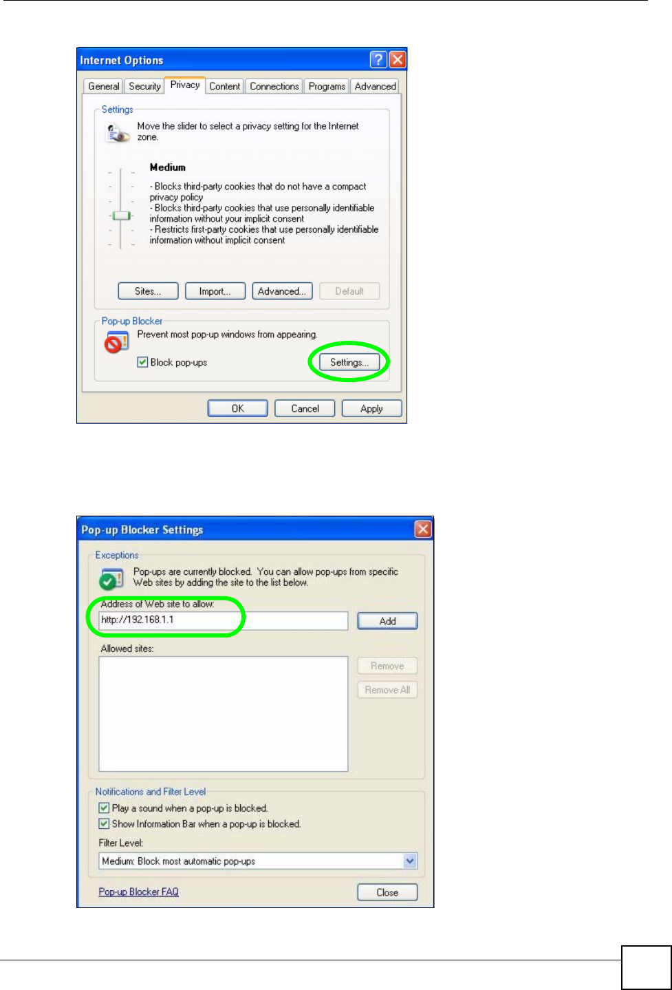
2Select Settings…to open the Pop-up Blocker Settings screen.
Appendix G Pop-up Windows, JavaScripts and Java Permissions
P-660HW-Dx v2 User’s Guide 335
Figure 198 Internet Options: Privacy
3Type the IP address of your device (the web page that you do not want to have blocked)
with the prefix “http://”. For example, http://192.168.167.1.
4Click Add to move the IP address to the list of Allowed sites.
Figure 199 Pop-up Blocker Settings
Appendix G Pop-up Windows, JavaScripts and Java Permissions
P-660HW-Dx v2 User’s Guide
336
5Click Close to return to the Privacy screen.
6Click Apply to save this setting.
JavaScripts
If pages of the web configurator do not display properly in Internet Explorer, check that
JavaScripts are allowed.
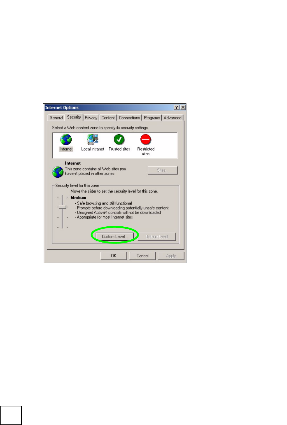
1In Internet Explorer, click Tools, Internet Options and then the Security tab.
Figure 200 Internet Options: Security
2Click the Custom Level... button.
3Scroll down to Scripting.
4Under Active scripting make sure that Enable is selected (the default).
5Under Scripting of Java applets make sure that Enable is selected (the default).
6Click OK to close the window.
Appendix G Pop-up Windows, JavaScripts and Java Permissions
P-660HW-Dx v2 User’s Guide 337
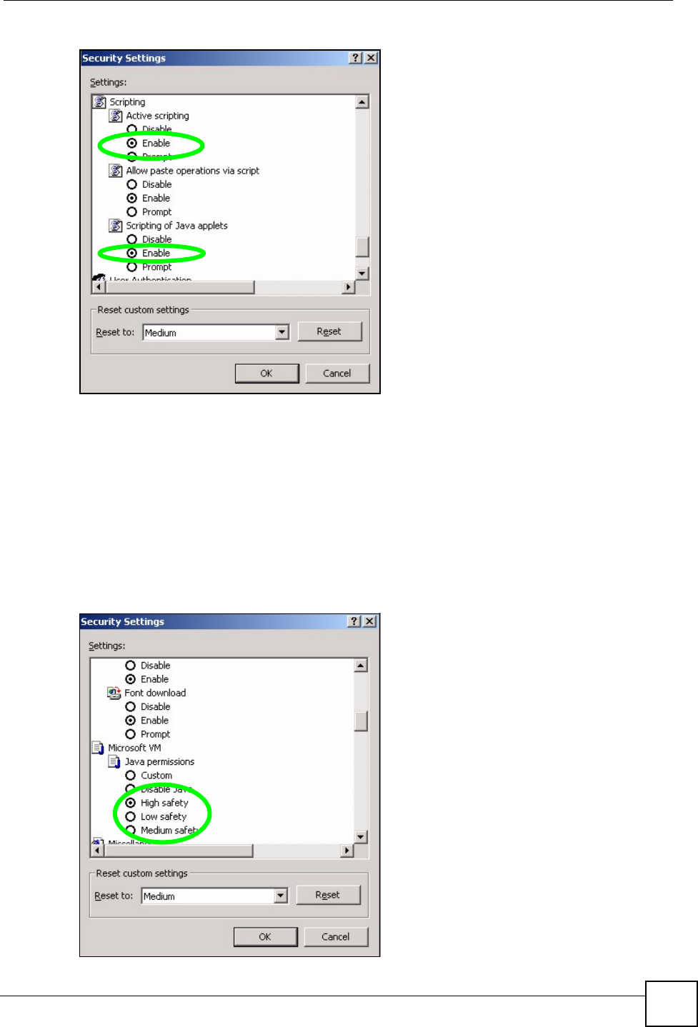
Figure 201 Security Settings - Java Scripting
Java Permissions
1From Internet Explorer, click Tools, Internet Options and then the Security tab.
2Click the Custom Level... button.
3Scroll down to Microsoft VM.
4Under Java permissions make sure that a safety level is selected.
5Click OK to close the window.
Figure 202 Security Settings - Java
Appendix G Pop-up Windows, JavaScripts and Java Permissions
P-660HW-Dx v2 User’s Guide
338
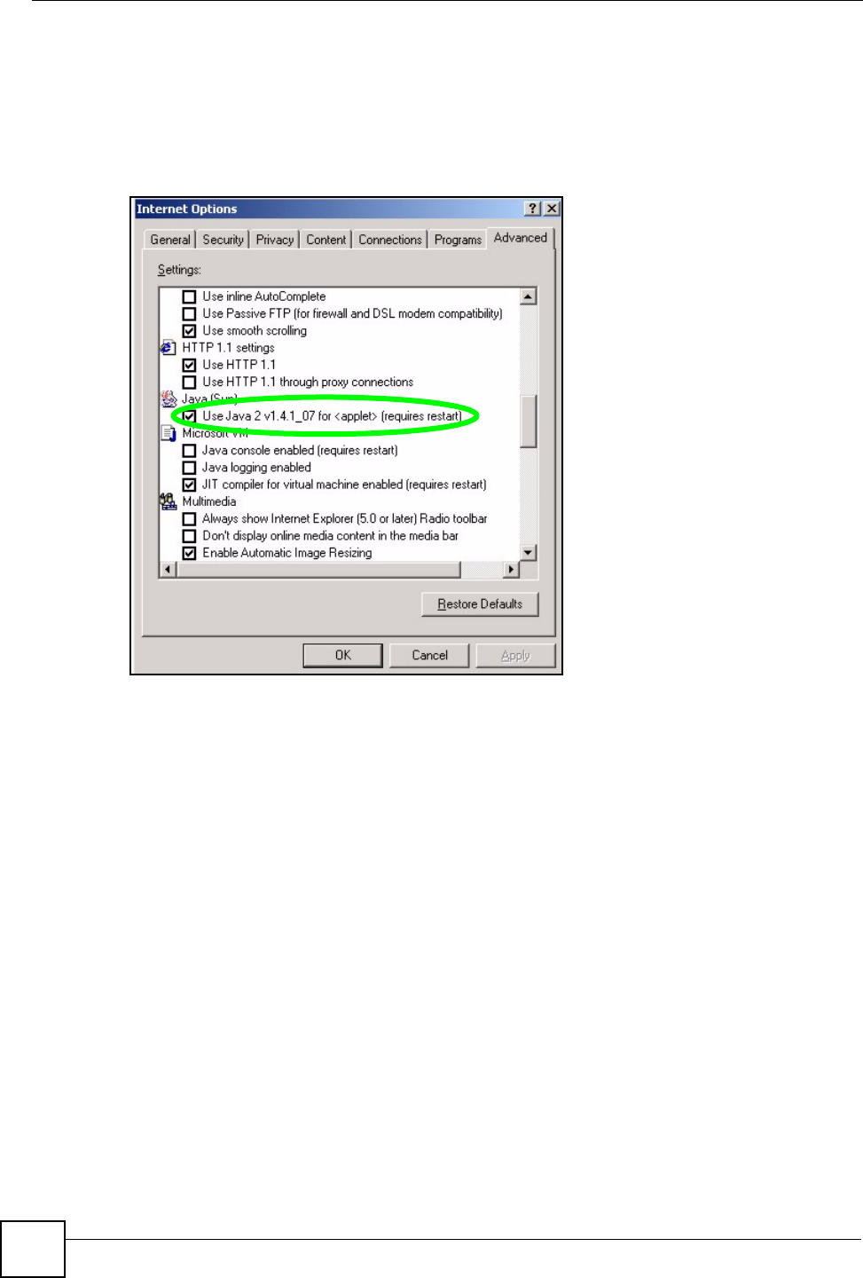
JAVA (Sun)
1From Internet Explorer, click Tools, Internet Options and then the Advanced tab.
2Make sure that Use Java 2 for <applet> under Java (Sun) is selected.
3Click OK to close the window.
Figure 203 Java (Sun)

P-660HW-Dx v2 User’s Guide 339
APPENDIX H
NetBIOS Filter Commands
The following describes the NetBIOS packet filter commands.
Introduction
NetBIOS (Network Basic Input/Output System) are TCP or UDP broadcast packets that
enable a computer to connect to and communicate with a LAN.
For some dial-up services such as PPPoE or PPTP, NetBIOS packets cause unwanted calls.
You can configure NetBIOS filters to do the following:
• Allow or disallow the sending of NetBIOS packets from the LAN to the WAN and from
the WAN to the LAN.
• Allow or disallow the sending of NetBIOS packets through VPN connections.
• Allow or disallow NetBIOS packets to initiate calls.
Display NetBIOS Filter Settings
This command gives a read-only list of the current NetBIOS filter modes for The ZyXEL
Device.
NetBIOS Display Filter Settings Command Example
Syntax: sys filter netbios disp
=========== NetBIOS Filter Status ===========
Between LAN and WAN: Block
IPSec Packets: Forward
Trigger Dial: Disabled
Appendix H NetBIOS Filter Commands
P-660HW-Dx v2 User’s Guide
340
The filter types and their default settings are as follows.
NetBIOS Filter Configuration
Syntax:sys filter netbios config <type> <on|off>
where
Table 148 NetBIOS Filter Default Settings
NAME DESCRIPTION EXAMPLE
Between LAN
and WAN
This field displays whether NetBIOS packets are blocked or forwarded
between the LAN and the WAN.
Block
IPSec Packets This field displays whether NetBIOS packets sent through a VPN
connection are blocked or forwarded.
Forward
Trigger dial This field displays whether NetBIOS packets are allowed to initiate
calls. Disabled means that NetBIOS packets are blocked from
initiating calls.
Disabled
<type> = Identify which NetBIOS filter (numbered 0-3) to configure.
0 = Between LAN and WAN
3 = IPSec packet pass through
4 = Trigger Dial
<on|off> = For type 0 and 1, use on to enable the filter and block NetBIOS
packets. Use off to disable the filter and forward NetBIOS packets.
For type 3, use on to block NetBIOS packets from being sent
through a VPN connection. Use off to allow NetBIOS packets to be
sent through a VPN connection.
For type 4, use on to allow NetBIOS packets to initiate dial backup
calls. Use off to block NetBIOS packets from initiating dial backup
calls.
Example commands
sys filter netbios
config 0 on
This command blocks LAN to WAN and WAN to LAN NetBIOS
packets.
sys filter netbios
config 3 on
This command blocks IPSec NetBIOS packets.
sys filter netbios
config 4 off
This command stops NetBIOS commands from initiating calls.
P-660HW-Dx v2 User’s Guide 341
APPENDIX I
Triangle Route
The Ideal Setup
When the firewall is on, your ZyXEL Device acts as a secure gateway between your LAN and
the Internet. In an ideal network topology, all incoming and outgoing network traffic passes
through the ZyXEL Device to protect your LAN against attacks.
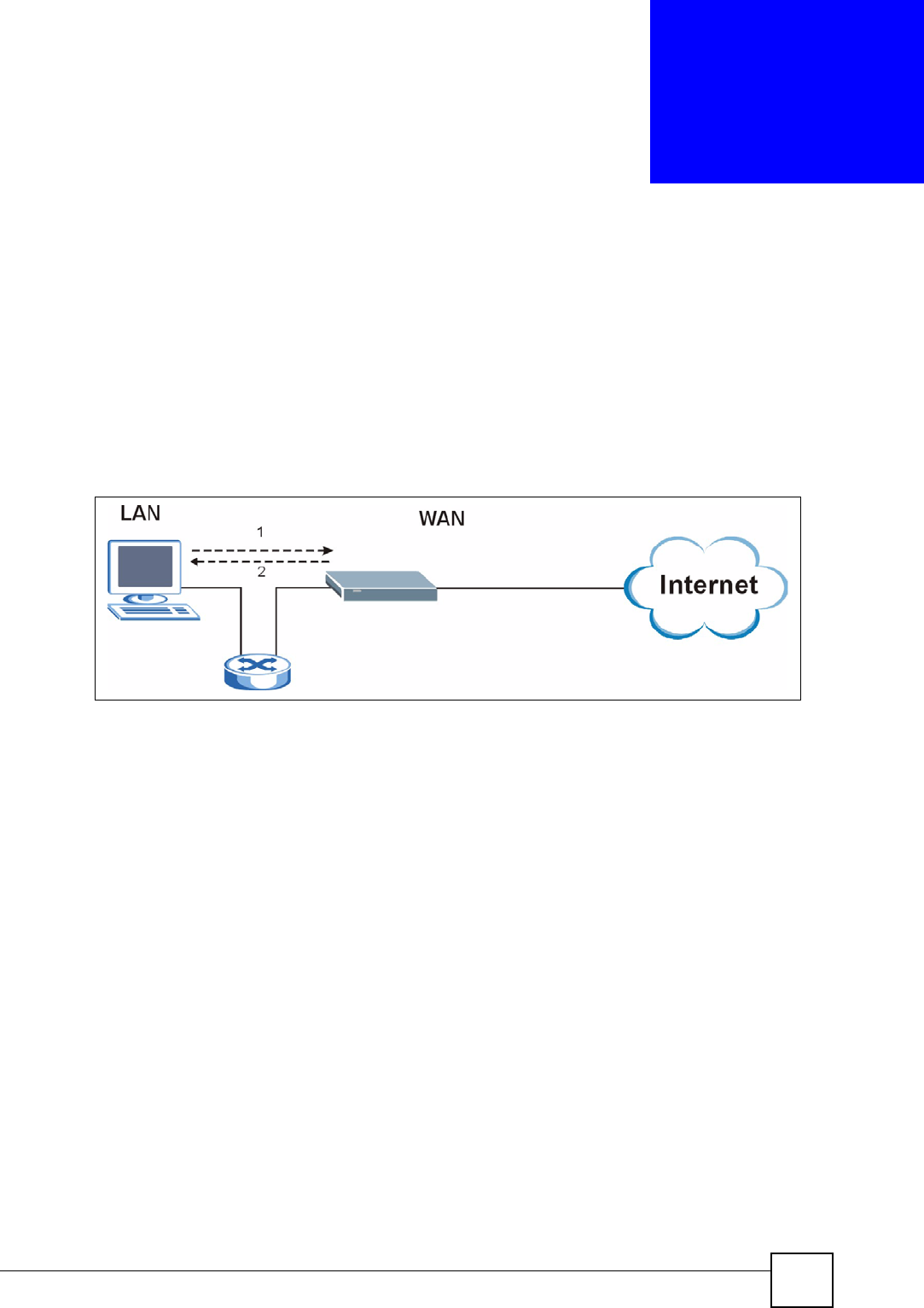
Figure 204 Ideal Setup
The “Triangle Route” Problem
A traffic route is a path for sending or receiving data packets between two Ethernet devices.
Some companies have more than one route to one or more ISPs. If the alternate gateway is on
the LAN (and it’s IP address is in the same subnet), the “triangle route” problem may occur.
The steps below describe the “triangle route” problem.
1A computer on the LAN initiates a connection by sending out a SYN packet to a
receiving server on the WAN.
2The ZyXEL Device reroutes the SYN packet through Gateway A on the LAN to the
WA N.
3The reply from the WAN goes directly to the computer on the LAN without going
through the ZyXEL Device.
As a result, the ZyXEL Device resets the connection, as the connection has not been
acknowledged.
Appendix I Triangle Route
P-660HW-Dx v2 User’s Guide
342
Figure 205 “Triangle Route” Problem
The “Triangle Route” Solutions
This section presents you two solutions to the “triangle route” problem.
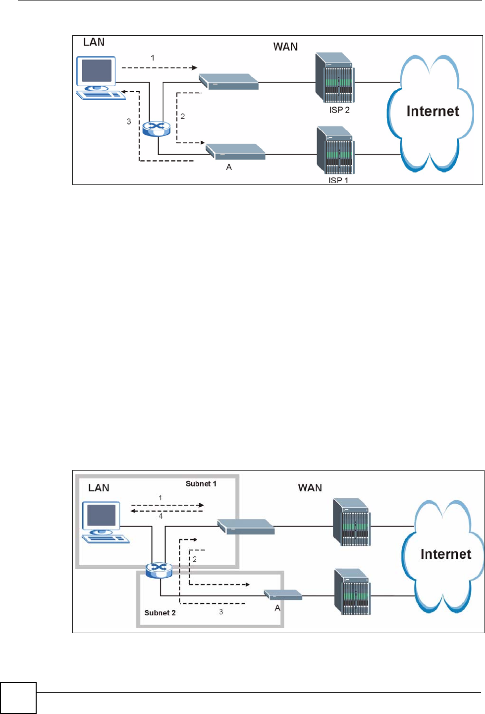
IP Aliasing
IP alias allows you to partition your network into logical sections over the same Ethernet
interface. Your ZyXEL Device supports up to three logical LAN interfaces with the ZyXEL
Device being the gateway for each logical network. By putting your LAN and Gateway B in
different subnets, all returning network traffic must pass through the ZyXEL Device to your
LAN. The following steps describe such a scenario.
1A computer on the LAN initiates a connection by sending a SYN packet to a receiving
server on the WAN.
2The ZyXEL Device reroutes the packet to Gateway A, which is in Subnet 2.
3The reply from WAN goes through the ZyXEL Device to the computer on the LAN in
Subnet 1.
Figure 206 IP Alias

P-660HW-Dx v2 User’s Guide 343
APPENDIX J
Legal Information
Copyright
Copyright © 2007 by ZyXEL Communications Corporation.
The contents of this publication may not be reproduced in any part or as a whole, transcribed,
stored in a retrieval system, translated into any language, or transmitted in any form or by any
means, electronic, mechanical, magnetic, optical, chemical, photocopying, manual, or
otherwise, without the prior written permission of ZyXEL Communications Corporation.
Published by ZyXEL Communications Corporation. All rights reserved.
Disclaimer
ZyXEL does not assume any liability arising out of the application or use of any products, or
software described herein. Neither does it convey any license under its patent rights nor the
patent rights of others. ZyXEL further reserves the right to make changes in any products
described herein without notice. This publication is subject to change without notice.
Trademarks
ZyNOS (ZyXEL Network Operating System) is a registered trademark of ZyXEL
Communications, Inc. Other trademarks mentioned in this publication are used for
identification purposes only and may be properties of their respective owners.
Certifications
Federal Communications Commission (FCC) Interference Statement
The device complies with Part 15 of FCC rules. Operation is subject to the following two
conditions:
• This device may not cause harmful interference.
• This device must accept any interference received, including interference that may cause
undesired operations.
This device has been tested and found to comply with the limits for a Class B digital device
pursuant to Part 15 of the FCC Rules. These limits are designed to provide reasonable
protection against harmful interference in a residential installation. This device generates,
uses, and can radiate radio frequency energy, and if not installed and used in accordance with
the instructions, may cause harmful interference to radio communications. However, there is
no guarantee that interference will not occur in a particular installation.

Appendix J Legal Information
P-660HW-Dx v2 User’s Guide
344
If this device does cause harmful interference to radio/television reception, which can be
determined by turning the device off and on, the user is encouraged to try to correct the
interference by one or more of the following measures:
1Reorient or relocate the receiving antenna.
2Increase the separation between the equipment and the receiver.
3Connect the equipment into an outlet on a circuit different from that to which the
receiver is connected.
4Consult the dealer or an experienced radio/TV technician for help.
FCC Radiation Exposure Statement
• This transmitter must not be co-located or operating in conjunction with any other antenna
or transmitter.
• IEEE 802.11b or 802.11g operation of this product in the U.S.A. is firmware-limited to
channels 1 through 11.
• To comply with FCC RF exposure compliance requirements, a separation distance of at
least 20 cm must be maintained between the antenna of this device and all persons.
注意 ! 依據 低功率電波輻射性電機管理辦法
第十二條 經型式認證合格之低功率射頻電機,非經許可,公司、商號或使用
者均不得擅自變更頻率、加大功率或變更原設計之特性及功能。
第十四條 低功率射頻電機之使用不得影響飛航安全及干擾合法通信;經發現
有干擾現象時,應立即停用,並改善至無干擾時方得繼續使用。
前項合法通信,指依電信規定作業之無線電信。低功率射頻電機須忍
受合法通信或工業、科學及醫療用電波輻射性電機設備之干擾
本機限在不干擾合法電臺與不受被干擾保障條件下於室內使用。
減少電磁波影響,請妥適使用
Notices
Changes or modifications not expressly approved by the party responsible for compliance
could void the user's authority to operate the equipment.
This device has been designed for the WLAN 2.4 GHz network throughout the EC region and
Switzerland, with restrictions in France.
This Class B digital apparatus complies with Canadian ICES-003.
Cet appareil numérique de la classe B est conforme à la norme NMB-003 du Canada.
Viewing Certifications
1Go to http://www.zyxel.com.
2Select your product on the ZyXEL home page to go to that product's page.

Appendix J Legal Information
P-660HW-Dx v2 User’s Guide 345
3Select the certification you wish to view from this page.
ZyXEL Limited Warranty
ZyXEL warrants to the original end user (purchaser) that this product is free from any defects
in materials or workmanship for a period of up to two years from the date of purchase. During
the warranty period, and upon proof of purchase, should the product have indications of failure
due to faulty workmanship and/or materials, ZyXEL will, at its discretion, repair or replace the
defective products or components without charge for either parts or labor, and to whatever
extent it shall deem necessary to restore the product or components to proper operating
condition. Any replacement will consist of a new or re-manufactured functionally equivalent
product of equal or higher value, and will be solely at the discretion of ZyXEL. This warranty
shall not apply if the product has been modified, misused, tampered with, damaged by an act
of God, or subjected to abnormal working conditions.
Note
Repair or replacement, as provided under this warranty, is the exclusive remedy of the
purchaser. This warranty is in lieu of all other warranties, express or implied, including any
implied warranty of merchantability or fitness for a particular use or purpose. ZyXEL shall in
no event be held liable for indirect or consequential damages of any kind to the purchaser.
To obtain the services of this warranty, contact ZyXEL's Service Center for your Return
Material Authorization number (RMA). Products must be returned Postage Prepaid. It is
recommended that the unit be insured when shipped. Any returned products without proof of
purchase or those with an out-dated warranty will be repaired or replaced (at the discretion of
ZyXEL) and the customer will be billed for parts and labor. All repaired or replaced products
will be shipped by ZyXEL to the corresponding return address, Postage Paid. This warranty
gives you specific legal rights, and you may also have other rights that vary from country to
country.
Registration
Register your product online to receive e-mail notices of firmware upgrades and information
at www.zyxel.com for global products, or at www.us.zyxel.com for North American products.

Appendix J Legal Information
P-660HW-Dx v2 User’s Guide
346

P-660HW-Dx v2 User’s Guide 347
APPENDIX K
Customer Support
Please have the following information ready when you contact customer support.
Required Information
• Product model and serial number.
• Warranty Information.
• Date that you received your device.
• Brief description of the problem and the steps you took to solve it.
Corporate Headquarters (Worldwide)
• Support E-mail: support@zyxel.com.tw
• Sales E-mail: sales@zyxel.com.tw
• Telephone: +886-3-578-3942
• Fax: +886-3-578-2439
• Web Site: www.zyxel.com, www.europe.zyxel.com
• FTP Site: ftp.zyxel.com, ftp.europe.zyxel.com
• Regular Mail: ZyXEL Communications Corp., 6 Innovation Road II, Science Park,
Hsinchu 300, Taiwan
Costa Rica
• Support E-mail: soporte@zyxel.co.cr
• Sales E-mail: sales@zyxel.co.cr
• Telephone: +506-2017878
• Fax: +506-2015098
• Web Site: www.zyxel.co.cr
• FTP Site: ftp.zyxel.co.cr
• Regular Mail: ZyXEL Costa Rica, Plaza Roble Escazú, Etapa El Patio, Tercer Piso, San
José, Costa Rica
Czech Republic
• E-mail: info@cz.zyxel.com
• Telephone: +420-241-091-350
• Fax: +420-241-091-359
• Web Site: www.zyxel.cz
• Regular Mail: ZyXEL Communications, Czech s.r.o., Modranská 621, 143 01 Praha 4 -
Modrany, Ceská Republika

Appendix K Customer Support
P-660HW-Dx v2 User’s Guide
348
Denmark
• Support E-mail: support@zyxel.dk
• Sales E-mail: sales@zyxel.dk
• Telephone: +45-39-55-07-00
• Fax: +45-39-55-07-07
• Web Site: www.zyxel.dk
• Regular Mail: ZyXEL Communications A/S, Columbusvej, 2860 Soeborg, Denmark
Finland
• Support E-mail: support@zyxel.fi
• Sales E-mail: sales@zyxel.fi
• Telephone: +358-9-4780-8411
• Fax: +358-9-4780 8448
• Web Site: www.zyxel.fi
• Regular Mail: ZyXEL Communications Oy, Malminkaari 10, 00700 Helsinki, Finland
France
• E-mail: info@zyxel.fr
• Telephone: +33-4-72-52-97-97
• Fax: +33-4-72-52-19-20
• Web Site: www.zyxel.fr
• Regular Mail: ZyXEL France, 1 rue des Vergers, Bat. 1 / C, 69760 Limonest, France
Germany
• Support E-mail: support@zyxel.de
• Sales E-mail: sales@zyxel.de
• Telephone: +49-2405-6909-69
• Fax: +49-2405-6909-99
• Web Site: www.zyxel.de
• Regular Mail: ZyXEL Deutschland GmbH., Adenauerstr. 20/A2 D-52146, Wuerselen,
Germany
Hungary
• Support E-mail: support@zyxel.hu
• Sales E-mail: info@zyxel.hu
• Telephone: +36-1-3361649
• Fax: +36-1-3259100
• Web Site: www.zyxel.hu
• Regular Mail: ZyXEL Hungary, 48, Zoldlomb Str., H-1025, Budapest, Hungary
Kazakhstan
• Support: http://zyxel.kz/support
• Sales E-mail: sales@zyxel.kz

Appendix K Customer Support
P-660HW-Dx v2 User’s Guide 349
• Telephone: +7-3272-590-698
• Fax: +7-3272-590-689
• Web Site: www.zyxel.kz
• Regular Mail: ZyXEL Kazakhstan, 43, Dostyk ave.,Office 414, Dostyk Business Centre,
050010, Almaty, Republic of Kazakhstan
North America
• Support E-mail: support@zyxel.com
• Sales E-mail: sales@zyxel.com
• Telephone: +1-800-255-4101, +1-714-632-0882
• Fax: +1-714-632-0858
• Web Site: www.us.zyxel.com
• FTP Site: ftp.us.zyxel.com
• Regular Mail: ZyXEL Communications Inc., 1130 N. Miller St., Anaheim, CA 92806-
2001, U.S.A.
Norway
• Support E-mail: support@zyxel.no
• Sales E-mail: sales@zyxel.no
• Telephone: +47-22-80-61-80
• Fax: +47-22-80-61-81
• Web Site: www.zyxel.no
• Regular Mail: ZyXEL Communications A/S, Nils Hansens vei 13, 0667 Oslo, Norway
Poland
• E-mail: info@pl.zyxel.com
• Telephone: +48 (22) 333 8250
• Fax: +48 (22) 333 8251
• Web Site: www.pl.zyxel.com
• Regular Mail: ZyXEL Communications, ul. Okrzei 1A, 03-715 Warszawa, Poland
Russia
• Support: http://zyxel.ru/support
• Sales E-mail: sales@zyxel.ru
• Telephone: +7-095-542-89-29
• Fax: +7-095-542-89-25
• Web Site: www.zyxel.ru
• Regular Mail: ZyXEL Russia, Ostrovityanova 37a Str., Moscow, 117279, Russia
Spain
• Support E-mail: support@zyxel.es
• Sales E-mail: sales@zyxel.es
• Telephone: +34-902-195-420
• Fax: +34-913-005-345

Appendix K Customer Support
P-660HW-Dx v2 User’s Guide
350
• Web Site: www.zyxel.es
• Regular Mail: ZyXEL Communications, Arte, 21 5ª planta, 28033 Madrid, Spain
Sweden
• Support E-mail: support@zyxel.se
• Sales E-mail: sales@zyxel.se
• Telephone: +46-31-744-7700
• Fax: +46-31-744-7701
• Web Site: www.zyxel.se
• Regular Mail: ZyXEL Communications A/S, Sjöporten 4, 41764 Göteborg, Sweden
Ukraine
• Support E-mail: support@ua.zyxel.com
• Sales E-mail: sales@ua.zyxel.com
• Telephone: +380-44-247-69-78
• Fax: +380-44-494-49-32
• Web Site: www.ua.zyxel.com
• Regular Mail: ZyXEL Ukraine, 13, Pimonenko Str., Kiev, 04050, Ukraine
United Kingdom
• Support E-mail: support@zyxel.co.uk
• Sales E-mail: sales@zyxel.co.uk
• Telephone: +44-1344 303044, 08707 555779 (UK only)
• Fax: +44-1344 303034
• Web Site: www.zyxel.co.uk
• FTP Site: ftp.zyxel.co.uk
• Regular Mail: ZyXEL Communications UK, Ltd.,11 The Courtyard, Eastern Road,
Bracknell, Berkshire, RG12 2XB, United Kingdom (UK)
“+” is the (prefix) number you dial to make an international telephone call.

Index
P-660HW-Dx v2 User’s Guide 351
Index
A
AAL5 76
access point
see AP
address assignment 94
Address Resolution Protocol
see ARP
ADSL
standards 34
ADSL line
reinitialize 258
ADSL standards 34
Advanced Encryption Standard
See AES.
AES 280
alerts 233
ALG 132
alternative subnet mask notation 303
antenna
directional 283
gain 283
omni-directional 283
antenna gain 116
Any IP 97, 267
how it works 98
note 98
Any IP Setup 100
AP 105
AP (access point) 273
application layer gateway 132
Application Layer Gateway. See ALG.
application-level firewalls 144
ARP 98
ATM Adaptation Layer 5
see AAL5
ATM loopback test 258
attack alert 174
attack types 148
attacks 233
auxiliary gateway 267
B
backup 253
backup gateway 267
backup settings 253
backup type 90
bandwidth 67
budget 193
bandwidth management 67, 187
bandwidth manager
class configuration 192
monitor 197
summary 191
Basic Service Set, See BSS 271
Basic wireless security 63
blocking time 173
brute-force attack 147
BSS 271
C
CA 278
CBR 83, 88
Certificate Authority
See CA.
certifications 343
notices 344
viewing 344
change password at login 41
channel 105, 273
interference 273
channel ID 109
Class of Service 194
Class of Service (CoS) 194
computer name 227, 228
configuration 94, 251, 253, 298
backup 253
restore 253, 254
upload 254
configuration text file 317
connection failure 267
contact information 347
content filtering 177
categories 177

Index
P-660HW-Dx v2 User’s Guide
352
schedule 178
trusted computers 179
URL keyword blocking 177
Continuous Bit Rate
see CBR
copyright 343
CoS 194
CTS (Clear to Send) 274
custom ports
creating / editing 164
customer support 347
customized services 164
D
date and time settings 229
default 255
default LAN IP address 39
default settings 253, 254
Denial of Service
see DoS
destination address 157
detection 54
device model number 251
DHCP 94, 95, 199, 227
diagnostic
DSL line 257
general 257
Differentiated Services 194
DiffServ Code Point (DSCP) 194
DiffServ Code Points 194
DiffServ marking rule 194
Digital Subscriber Line Access Multiplexer
see DSLAM
dimensions 265
disclaimer 343
DNS 94, 210
domain name 94, 134, 227, 228
Domain Name System
see DNS
DoS 144, 145, 173
basics 145
types 146
downstream 33, 34
DS Field 194
DS field 194
DSCPs 194
DSL
reinitialize 258
DSLAM 33
dynamic DNS 199
dynamic WEP key exchange 279
DYNDNS wildcard 199
E
EAP Authentication 277
ECHO 134
E-Mail 127
e-mail 67
log example 236
Encapsulated Routing Link Protocol
see ENET ENCAP
encapsulation 75, 76
PPP over Ethernet 75
PPPoA 76
RFC 1483 76
encryption 107, 110, 280
and local (user) database 107
key 108
WPA compatible 108
ENET ENCAP 75
ESS 272
ESSID 109
Ethernet adapter card 285
Extended Service Set IDentification
see ESSID
Extended Service Set, See ESS 272
Extended wireless security 63
F
factory defaults 253, 255
fairness-based scheduler 189
FCC interference statement 343
File Transfer Protocol
see FTP
filename extension 251
finger 134
firewall
access methods 155
address type 163
alerts 158
anti-probing 171
commands 311
creating/editing rules 161
custom ports 164
enabling 158
firewall vs filters 153

Index
P-660HW-Dx v2 User’s Guide 353
guidelines for enhancing security 152
introduction 144
LAN to WAN rules 158
policies 155
rule checklist 156
rule configuration key fields 157
rule logic 156
rule security ramifications 156
services 169
types 143
when to use 153
firmware 33, 251
upgrade 251
upload 251
upload error 252
fragmentation threshold 274
FTP 67, 134, 204, 207
restrictions 204
full rate 36
H
half-open sessions 173
help 42
hidden node 273
hide SSID 106
host 228, 229
host name 227
HTTP 134, 144, 145, 251
hub 33
humidity 265
Hypertext Transfer Protocol
see HTTP
I
IANA 95, 96, 164, 308
IBSS 271
ICMP 147, 171
ICMP echo 147
IEEE 802.11g 275
IGMP 96, 97
Independent Basic Service Set
See IBSS 271
initialization vector (IV) 280
Integrated Services Digital Network
see ISDN
internal SPTGEN 317
FTP upload example 319
points to remember 318
text file 317
Internet access 34, 53
wizard setup 53
Internet Assigned Numbers Authority
See IANA 308
see IANA 95
Internet Control Message Protocol
see ICMP
Internet Group Multicast Protocol
see IGMP
IP address 95, 134, 135, 136, 265
IP address assignment 77
ENET ENCAP 77
PPPoA or PPPoE 77
RFC 1483 77
IP policy routing (IPPR) 267
IP pool 101
setup 94
IP protocol type 169
IP spoofing 146, 148
ISDN 33
L
LAN setup 93
LAN TCP/IP 95
LAN to WAN rules 158
LAND 146, 147
LEDs 35
local (user) database 106
and encryption 107
logs 233
alerts 233
configuring 234
descriptions 237
e-mail 236
loopback test 258
M
MAC address 106
MAC address filter 106
action 121
MAC address filtering 121
MAC filter 121
maintenance 253
Management Information Base
see MIB

Index
P-660HW-Dx v2 User’s Guide
354
managing the device
good habits 35
using FTP. See FTP.
using Telnet. See command interface.
using the command interface. See command
interface.
maximize bandwidth usage 189
Maximum Burst Size
see MBS
max-incomplete high 173
max-incomplete low 173
MBS 79, 83, 88
media access control
see MAC
Message Integrity Check (MIC) 280
metric 78
MIB 208
multicast 96
multiplexing 76
LLC-based 76
VC-based 76
multiprotocol encapsulation 76
N
nailed-up connection 77
NAT 95, 129, 134, 135, 308
address mapping rule 139
application 130
definitions 129
how it works 130
mapping types 131
mode 133
what it does 130
NAT traversal 213
navigating the web configurator 42
NetBIOS 339
commands 148
Network Address Translation
see NAT
Network Basic Input / Output System
see NetBIOS
network disconnect icon 252, 254
network management 134
NNTP 134
O
one-minute high 173
one-minute low 173
P
packet filtering 153
when to use 153
packet filtering firewalls 143
Pairwise Master Key (PMK) 280, 282
PCR 78, 83, 88
Peak Cell Rate
see PCR
Per-Hop Behavior 194
PHB (Per-Hop Behavior) 194
ping 257
ping of death 146
Point to Point Protocol over ATM Adaptation Layer 5
(AAL5) 76
point-to-point protocol over ATM
Point-to-Point Tunneling Protocol
see PPTP
POP3 134, 145
power specifications 265
PPPoA 76
PPPoE 75
Benefits 75
PPTP 134
preamble mode 275
Priorities 122
priority 191, 193
priority-based scheduler 188
product registration 345
PSK 280
Q
quick start guide 39
R
RADIUS 276
message types 277
messages 277
shared secret key 277
RADIUS server 107
reboot 255

Index
P-660HW-Dx v2 User’s Guide 355
registration
product 345
related documentation 3
remote management and NAT 204
remote management limitations 204
reset 255
reset button 42
resetting the ZyXEL device 42
restart 251, 255
restore configuration 254
restore settings 254
RFC 1483 76
RFC 1631 129
RFC-1483 77
RFC-2364 76
RIP 96
Direction 96
Version 96
Routing Information Protocol
see RIP
RTS (Request To Send) 274
threshold 273, 274
rules 158
checklist 156
key fields 157
LAN to WAN 158
logic 156
predefined services 169
S
safety warnings 6
save settings 253
saving the state 148
scheduler 188
fairness-based 189
priority-based 188
SCR 79, 83, 88
screws 269
security
general 152
ramifications 156
Server 132
server 131, 132, 230
service 157
service set 109
Service Set IDentity
See SSID
service type 165
services 134
settings
backup 253
defaults 253
restore 254
setup, general 227
Single User Account
see SUA
SIP
ALG 132
SIP application layer gateway 132
SMTP 134
smurf 147
SNMP 134, 207
manager 208
MIBs 209
source address 157
splitters 36
SPTGEN 317
command examples 331
text file format 317
SSID 105
hide 106
stateful inspection 143, 144, 148, 149
and the ZyXEL device 150
process 149
static route 183
SUA 132
SUA vs NAT 132
subnet 267, 301
subnet mask 95, 163, 302
subnetting 304
Sustain Cell Rate
see SCR
switch 265
SYN Flood 146, 147
SYN-ACK 146
syntax conventions 4
syslog 168
system errors 233
system name 227, 228
System Parameter Table Generator
see SPTGEN
system restart 255
system timeout 204
T
TCP maximum incomplete 173
TCP security 150
TCP/IP 145, 146, 285

Index
P-660HW-Dx v2 User’s Guide
356
TCP/IP address 257
teardrop 146
Teln e t 67, 205
temperature 265
Temporal Key Integrity Protocol (TKIP) 280
TFTP restrictions 204
three-way handshake 146
threshold values 172
time and date settings 229
timeout 204
tools 251
traceroute 148
trademarks 343
traffic redirect 89, 91, 267
traffic shaping 78
transmission rates 33
triangle route 341
solutions 342
U
UBR 83, 88
UDP/ICMP security 151
Unspecified Bit Rate
see UBR
UPnP 213
application 213
Forum 214
security issues 213
UPnP installation 215
Windows Me 215
Windows XP 216
upper layer protocols 150, 151
upstream 33, 34
user authentication 106
local (user) database 106
RADIUS server 107
weaknesses 107
user name 200
V
Variable Bit Rate
see VBR
VBR 83, 88
VC 76
VC-based multiplexing 76
VCI 77
Virtual Channel Identifier
see VCI
virtual circuit
see VC
Virtual Path Identifier
see VPI
Voice over IP
see VoIP
VoIP 68
VPI 77
W
wall-mounting 265
WAN 75
backup 89
WAN setup 75
WAN to LAN rules 158
warranty 345
note 345
web configurator 39, 42, 151, 152, 157
screen summary 43
WEP 110
encryption 112
Wide Area Network
see WAN
Wi-Fi Multimedia QoS 122
Wi-Fi Protected Access 279
wireless client 105
wireless client WPA supplicants 281
wireless LAN 108
wireless network 105
basic guidelines 105
wireless networks
channel 105
encryption 107
MAC address filter 106
security 106
SSID 105
wireless security 106, 275
wizard icon 53
WLAN
interference 273
security parameters 282
world wide web 204
WPA 279
key caching 280
pre-authentication 280
user authentication 280
vs WPA-PSK 280
wireless client supplicant 281

Index
P-660HW-Dx v2 User’s Guide 357
with RADIUS application example 281
WPA compatibility 108
WPA2 279
user authentication 280
vs WPA2-PSK 280
wireless client supplicant 281
with RADIUS application example 281
WPA2-Pre-Shared Key 279
WPA2-PSK 279, 280
application example 281
WPA-PSK 279, 280
application example 281
WWW 127
Z
zero configuration Internet access 80
ZyXEL’s firewall
introduction 144

Index
P-660HW-Dx v2 User’s Guide
358